Embed Size (px)
Citation preview

Designation: X XXXX-XX
Work Item Number: WK17170
Date: 10/10/08
Standard Test Method for The Determination of Asbestos in Soil1
This standard is issued under the fixed designation X XXXX; the number immediately following the designation indicates the year of original adoption or, in the case of revision, the year of last revision. A number in parentheses indicates the year of last reapproval. A superscript epsilon (ε) indicates an editorial change since the last revision or reapproval.
1. Scope
1.1This test method covers a procedure to: (a) identify asbestos in soil, (b) provide an estimate of the concentration of asbestos in the sampled soil (dried), and (c) optionally to provide a concentration of asbestos reported as the number of asbestos structures per gram of sample.
1.2 1This test method produces results that may be used for evaluation of sites contaminated by construction, mine and manufacturing wastes, deposits of naturally-occurring asbestos and other sources of interest to the investigator.
1.3 This test method describes the gravimetric, sieve, and laboratory procedures for preparing the soil for analysis as well as the identification and quantification of any asbestos detected.
1.3.1 Asbestos is identified by techniques using polarized light microscopy (PLM) and transmission electron microscopy (TEM) or both and is based on morphology, optical properties and for TEM selected area electron diffraction (SAED), and energy dispersive X-ray analysis (EDXA). Some information about fiber size may also be determined. The PLM and TEM methods use different definitions and size criteria for fibers and structures. Separate data sets may be produced.
1.4 This test method has an analytical sensitivity of <0.25% by weight with optional procedures to allow for an analytical sensitivity of 0.1% by weight.
1.5 The values stated in Standard International Units (SI) are to be regarded as the standard. The values given in parentheses are for information only.
1.6 Hazard--Asbestos fibers are acknowledged carcinogens. Breathing asbestos fibers can result in disease of the lungs including asbestosis, lung cancer, and mesothelioma. Precautions should be taken to avoid creating and breathing airborne asbestos particles when sampling and analyzing materials suspected of containing asbestos. (Regulatory requirements addressing asbestos are defined by the U.S. Environmental Protection Agency (40 CFR Part 61, Subpart M and 40 CFR Part 763, Subpart E) and the Occupational Safety and Health Administration (29 CFR Parts 1910, 1916, and 1926).
1.7 This standard does not purport to address all of the safety concerns, if any, associated with its use. It is the responsibility of the user of this standard to establish appropriate safety and health practices and determine the applicability of regulatory limitations prior to use.
2. Referenced Documents
2.1ASTM Standards2
D 1193 Specification for Reagent WaterD 6281 Standard Test Method for Airborne Asbestos Concentration in Ambient and IndoorAtmospheres as Determined by Transmission Electron Microscopy Direct Transfer (TEM)
1This test method is under the jurisdiction of ASTM Committee D22 Air Quality and is the direct responsibility of Subcommittee D22.07Sampling and Analysis of Asbestos.
Current edition approved XXX. XX, XXXX. Published XX XXXX.2 For referenced ASTM standards, visit the ASTM website, www.astm.org, or contact ASTM Customer Service at [email protected]. For Annual Book of ASTM Standards volume information, refer to the standard's Document Summary page on the ASTM website.
1
This document is not an ASTM standard; it is under consideration within an ASTM technical committee but has not received all approvals required to become an ASTM standard. You agree not to reproduce or circulate or quote, in whole or in part, this document outside of ASTM Committee/Society activities, or submit it to any other organization or standards bodies (whether national, international, or other) except with the approval of the Chairman of the Committee having jurisdiction and the written authorization of the President of the Society. If you do not agree with these conditions please immediately destroy all copies of the document. Copyright ASTM International, 100 Barr Harbor Drive, West Conshohocken, PA 19428. All Rights Reserved.

X XXXX
D 3670 Guide for Determination of Precision and Bias of Methods of Committee D22E 11 Specification for Wire Cloth and Sieves for Testing Purposes
2.2 OSHA Standards3
OSHA, 29 CFR Part 1910 Occupational Safety and Health Standards OSHA, 29 CFR Part 1926 Safety and Health Regulations for Construction
2.3 EPA Standards4
EPA 600/R-93 116 Method for the Determination of Asbestos in Bulk Building MaterialsEPA 600/M4-82-020 Interim Method for the Determination of Asbestos in Bulk Insulation SamplesUSEPA 40 CFR Part 61, Subpart M National Emission Standard for AsbestosUSEPA 40 CFR Part 763, Subpart E Asbestos-Containing Materials in School Rule
2.4 ISO Standards5
ISO (the International Organization for Standardization), Ambient Air -Determination of Asbestos Fibers –Direct Transfer Transmission Electron Microscopy Method, ISO 10312:1995, (1st Ed. 1995-05-01).
3. Terminology
3.1 Definitions: 3.1.1 asbestiform — type of fibrous habit in which the fibers are separable into thinner fibers and ultimately
intofibrils. 3.1.1.1 Discussion--This habit accounts for greater flexibility and higher tensile strength than other habits of the
same mineral. For more information on asbestiform mineralogy, see Refs (1), (2), (3) and (9). 3.1.2 asbestos —collective term that describes a group of naturally occurring, inorganic, highly fibrous,
silicate-dominated minerals that are easily separated into long, thin, flexible fibers when crushed or processed. 3.1.2.1 Discussion--Included in the definition are the asbestiform varieties of: serpentine (chrysotile), riebeckite
(crocidolite), grunerite (amosite), anthophyllite (anthophyllite asbestos), tremolite (tremolite asbestos), and actinolite (actinolite asbestos). The amphibole mineral compositions are defined according to nomenclature of the International Mineralogical Association (3) and (9).
Asbestos Chemical Abstract Service No.
Chrysotile 12001-29-5Crocidolite 12001-28-4Amosite 12172-73-5Anthophyllite asbestos
77536-67-5
Tremolite asbestos 77536-68-6Actinolite asbestos 77536-66-4
3.1.3 fibril, n—single fiber that cannot be separated into smaller components without losing its fibrous properties or appearance.
3.1.4 aspect ratio —ratio of the length of a fibrous particle to its average width.3.1.5 bundle —USE ASTM 6281 Set of definitions -----tructure composed of three or more fibers in a parallel
arrangement with the fibers closer than one fiber diameter to each other. 3.1.6 cluster —structure with fibers in a random arrangement such that all fibers are intermixed and no single
fiber is isolated from the group; groupings of fibers shall have more than two points touching. 3.1.7 chunks —materials that are of an amount and size that remain in the ~19mm (2.0 cm) sieve after sieving.3.1.8 fiber(TEM) —structure having a minimum length of 0.5um, an aspect ratio of 3:1 or greater, and
substantially parallel sides (4).
3 Available from the Occupational Safety and Health Administation, 200 Constitution Ave., N.W., Wahsington, DC 20210.4 Available from the U.S. Environmental Protection Agency, Ariel Rios Bldg., 1200 Pennsylvania Ave., N.W., Washington, DC 20460.5 Available from the International Organization for Standardization (ISO), 1, ch. de la Voie-Creuse, Case postale 56, CH-1211 Geneva 20, Switzerland
2

X XXXX
3.1.9 fibrous (PLM) —of a mineral composed of parallel, radiating, or interlaced aggregates of fibers, from which the fibers may or may not be separable, that is, the crystalline aggregate may be referred to as fibrous even if it is not composed of separable fibers, but has that distinct appearance.
3.1.9.1 Discussion--The term fibrous is used in a general mineralogical way to describe aggregates of grains that crystallize in a needle-like habit and appear to be composed of fibers. Fibrous has a much more general meaning than asbestos. While it is correct that all asbestos minerals can have a fibrous habit not all minerals having fibrous habits are asbestos.
3.1.10 matrix —structure in which one or more fibers, or fiber bundles that are touching, are attached to or partially concealed by a single particle or connected group of nonfibrous particles. The exposed fiber shall meet the fiber definition (see 3.1.8).
3.1.11 soil —(reference ASTM definition D2216-98/D653-07- maximum size ~19mm) loose top layer of the earth's surface consists of rock and mineral particles mixed with decayed organic matter.
3.1.12 estimated weight percent –defined as the visual area estimation of asbestos in a sieved fraction multiplied by the weight of the fraction analyzed.
3.1.13 structures (TEM) —term that is used to categorize all the types of asbestos particles that are recorded during the analysis (such as fibers, bundles, clusters, and matrices).
3.1.14 visual area estimate (VAE) – a quantitative estimate of the amount of asbestos present most readily obtained by visual comparison of the bulk sample and slide preparations to other slide preparations and bulk samples with known amounts of asbestos present in them . Given that soils are typically heterogeneous sieving the soil helps to achieve similar particle size and texture for subsequent microscopic evaluation and estimation.
4. Summary of Test Method
4.1The soil sample is dried and sieved with sieves arranged from top to bottom; >19mm, >2-mm- 19mm (coarse fraction), >106-µm to <2-mm (medium fraction), and <106-µm (fine fraction). Weights for each fraction are measured and recorded. During analysis the >19mm fraction is analyzed using stereomicroscopy and PLM for large chunks and reported separately. The result is not included in the final result of the other three sieves. Any building material debris collected along with the soil sample is also analyzed and reported separately.The coarse fraction (>2-mm to < 19mm), medium fraction (>106-µm to <2-mm) fine fraction (<106 µm) are all analyzed by PLM calibrated visual area estimation (VAE). Results for the PLM analyses are expressed in estimated weight percent. Further analysis of the fine fraction may be performed by TEM to provide size data and concentration of asbestos reported as the number of asbestos structures per gram of sample and or estimated weight percent.
4.2Stopping rules -- A progressive analysis approach is utilized beginning with the coarsest sieved fraction. The analysis may be terminated if 5% asbestos or greater is observed in any sieved fraction (including the discarded <19mm fraction) by VAE. If < 5% is observed in all fractions then the final result is produced as outlined in Section 14.0. Additional analysis (optionally) of the fine fraction by TEM may also be performed when the final result is < 5% or no asbestos is observed by PLM.
5. Significance and Use
5.1 This analysis method is used for the testing of soil samples for asbestos. The emphasis is on detection and analysis of sieved particles and free fibers in the soil. Debris identifiable as bulk building material that is readily separable from the soil is to be analyzed separately.
5.1.1 This test method does not describe procedures or techniques required to evaluate the safety or habitability of buildings or outdoor areas potentially contaminated with asbestos-containing materials or compliance with federal, state, or local regulations or statutes. It is the user's responsibility to make these determinations.
5.2 Whereas this test method produces results that may be used for evaluation of sites contaminated by construction, mine and manufacturing wastes, deposits of naturally-occurring asbestos and other sources of interest to the investigator, the application of the results to such evaluations and the conclusions drawn therefrom, including any assessment of risk or liability, is beyond the scope of this method and is the responsibility of the investigator.
3
X XXXX
6. Interferences
6.1 The following minerals have properties (that is, chemical or crystalline structure) that are very similar to asbestos minerals and may interfere with the analysis by causing a false positive to be recorded during the test. Therefore, literature references for these materials shall be maintained in the laboratory for comparison to asbestos minerals so that they are not misidentified as asbestos minerals.
6.1.1 Antigorite, 6.1.2 Palygorskite (Attapulgite), 6.1.3 Halloysite, 6.1.4 Pyroxenes,6.1.5 Sepiolite, 6.1.6 Vermiculite scrolls, 6.1.7 Fibrous talc, and 6.1.8 Hornblende and other amphiboles other than those listed in 3.1.2.6.1.9 Other clays such as chlorite associated with talc deposits6.1.10 Scrolled minerals (lizardite)
7. Materials and Equipment
7.1 Analytical Balance—Balances or scales used in testing fine and coarse aggregate shall have readability and accuracy to two decimal places (0.01g). For the fine fraction an analytical balance must be able to read to four decimal places (0.0001g).
7.2 Sieves—The sieve meshes and standard sieve frames shall conform to the requirements of Specification E 11 – Specification for Wire Cloth and Sieves for Testing Purposes. (3” or 8” diameter);ASTM type;3/4”(ISO19mm), No. 10 (2 mm), No.140 (106 um) and collection pan (with drain outlet when using wet sieve procedure)
7.3 Mechanical Sieve Shaker—A mechanical sieving device, if used, shall create motion of the sieves at a frequency of 60Hz and cause the particles to bounce, tumble, or otherwise turn so as to present different orientations to the sieving surface.
7.4 Laboratory Oven—An oven of appropriate size capable of maintaining a uniform temperature of 110 ± 5°C (230 ± 9°F).
7.5 Transmission Electron Microscope (TEM), an 80- to 120-kV TEM, capable of performing electron diffraction, with a fluorescent screen inscribed with calibrated gradations, is required. The TEM shall be equipped with an energy dispersive X-ray spectrometer (EDXA) and it shall have a scanning transmission electron microscopy (STEM) attachment or be capable of producing a spot size of less than 250 nm in diameter in crossover.
7.6 EDXA -The EDXA system (detector and multichannel analyzer), under routine analysis conditions, meets the following specifications; <175 eV or better resolution at Mn Kα peak, proven detection of Na peak in standard crocidolite or equivalent, capable of obtaining statistically significant Mg and Si peaks from a single fibril of chrysotile, consistent relative sensitivity factors over large areas of the specimen grid.
7.7 High-Vacuum Carbon Evaporator, with rotating stage 7.8 Exhaust or Fume Hood; capable of 25 linear meters/minute (80 fpm) flow rate 7.9 Stereo Microscope; approximately 10-45X, with light source;7.10 Side Arm Filter Flask, 1000 mL7.11 Cabinet-Type Desiccator, or low-temperature drying oven. 7.12 Ultrasonic Bath, Branson or equivalent 7.13 Vacuum Pump, that can maintain a pressure of 92 kPa. 7.14 Polarized Light Microscope; binocular or monocular with cross hair reticule (or functional equivalent), low
(≥5X and ≤15X), medium (>15X and <40X), and high (≥40X) objectives, light source, 360-degree rotatable stage, substage condenser with iris diaphragm, polarizer and analyzer that can be placed at 90o to each other, accessory slot at 45o to polarizers for wave plates and compensators, wave retardation plate (~ 550 nm retardation), dispersion staining objective complete with accessories (optional), test slide (or a standard such as SRM 1866) for aligning the cross hairs with the privileged directions of the polarizer and analyzer.
7.15 Ultrasonic Bath, tabletop model (100 W).7.16 Purity of Reagents—Reagent-grade chemicals shall be used in all tests. Unless otherwise indicated, it is
intended that all reagents conform to the specifications of the Committee on Analytical Reagents of the American
4

X XXXX
Chemical Society where such specifications are available. Other grades may be used, provided it is first ascertained that the reagent is of sufficiently high purity to permit its use without lessening the accuracy of the determination.6
7.17 Purity of Water—Unless otherwise indicated, references to water shall be understood to mean reagent water as defined by Type II of Specification D 1193.
7.18 Plastic Sample Containers, with wide mouth screw cap (500 mL) or equivalent sealable container.7.19 Waterproof Markers 7.20 Forceps (Tweezers)7.21 Carbon-coated finder grids (filter substrate), 200mesh 7.22 Graduated Pipettes (1-, 5-, or 10-mL Sizes), glass or plastic.7.23 Filter Funnel Assemblies, either glass or disposable plastic and using either a 25- or 47-mm diameter filter. 7.24 Mixed Cellulose Ester (MCE) Membrane Filters, 25- or 47-mm diameter, 0.45 and 5-µm pore size.7.25 Polycarbonate (PC) Filters, 25- or 47-mm diameter, 0.4-µm pore size.7.26 Storage Containers, for the 25- or 47-mm filters (for archiving).7.27 Glass Slides, approximately 76 by 25 mm in size.7.28 Scalpel Blades, No. 10 or equivalent.7.29 Cover slips7.30 Non-asbestos Mineral, references as outlined in 6.1.7.31 Asbestos Standards, NIST traceable as outlined in 3.1.2.7.32 Petri Dishes, large glass, approximately 90 mm in diameter.7.33 Jaffe Washer, stainless steel or aluminum mesh screen, 30 to 40 mesh, approximately 75 by 50 mm. 7.34 Carbon Rods for evaporation of carbon film7.35 Lens Tissue7.36 Ashless Filter Paper Filters, 90-mm diameter.7.37 Wash Bottles, plastic.7.38 Reagent Alcohol, HPLC grade (Fisher A995 or equivalent).7.39 Diffraction Grating Replica, 2160 lines/mm 7.40 Disposable aluminum pans7.41 Scalpel, #20 or #10 blades7.42 Centrifuge tube, 15ml
10. Sampling Procedure
10.1 A representative portion of the soil sample material is collected in a rigid, sealable, non-breakable container (250-cm3.) Soil samples shall be collected in a manner that meets the requirements of this method and the needs of the investigator for whom the soil is being analyzed.
10.2 This section (see Ref 10) describes surface sampling from a relatively flat horizontal surface and subsurface (core) sampling. See Figure 1. It is the responsibility of the investigator to determine which procedure to use and also whether conditions exist at the site requiring appropriate modifications to be made to either procedure.
10.3 These collection methods are appropriate for contaminated soil in which the source of asbestos fibers is external and naturally occurring asbestos (NOA) in which the asbestos fibers originated in the soil. Examples of the former include debris from disposal of building materials and mine waste tailings. The latter may include veins of asbestos in construction excavations, deposits of tailings concentrated by runoff, and detritus caused by weathering of rock and soil and other naturally occurring deposits from quarries or mining activities. The methods are intended to collect “free fibers” that have become dissociated from pieces of building material debris and discrete pieces of NOA by collecting the soil in which the “free fibers” are entrained.
6Reagent Chemicals, American Chemical Society Specifications, American Chemical Society, Washington, DC. For suggestions on the testing of
reagents not listed by the American Chemical Society, see Analar Standards for Laboratory Chemicals, BDH Ltd., Poole, Dorset, U.K., and the
United States Pharmacopeia and National Formulary, U.S. Pharmaceutical Convention, Inc. (USPC), Rockville, MD.
5

X XXXX
Figure 1. Section through loose soil, hardpan, and trench (1)
10.4 Sample Collection Equipment10.4.1 Sample containers--Rigid, sealable, non-breakable containers of sufficient size to hold 250-cm3 dry soil. 10.4.2 Template--Cleanable plastic or metal templates with a square central hole of a size delineating the area to
be sampled. Disposable cardboard templates are acceptable for one-time use.10.4.3 Depth gauge--Cleanable rigid metal or plastic guides to measure the depth of samples taken (optional).10.4.4 Scoop--A rigid metal or plastic scoop with a sharp edge. For sampling the surface of hardpan, use a metal
scoop with a pointed tip capable of scratching the surface.10.4.5 Spray bottle--A plastic bottle filled with soapy water with the nozzle set to spray a fine mist.10.4.6 Tape-- To seal sample container 10.4.7 Plastic bags--Freezer bags of one gallon (4 L) size.10.4.8 Core sampler – For collection of sub-surface samples.10.5. Surface Sample Collection Procedure 10.5.1 Either loose soil or soil from the top surface of intact undisturbed hardpan shall be collected. 10.5.2 Sample area selection – If possible, select an area for sampling that is representative of the type of
asbestos material and/or contamination event under investigation, such as abandoned pipe insulation. If there is visual evidence of potentially asbestos-containing material in the form of debris from building material or free fibers from mine or manufacturing wastes, note its presence. However, as the objective is collection of the contaminated soil and not visible debris or waste, select an area in which these objects are not abundant. Select an area that is free of contamination by solvents, oils, lead paint, grease, or other hazardous or interfering substances.
10.5.3 Sample area preparation--Secure the area against unauthorized entry and inadvertent disturbance. Determine the depth of loose soil and select a template size from Table 1. Lay the template on the ground where there is the least amount of visible debris or free fiber. If the sampling location does not accommodate a template with a square hole, a template may be fabricated in the field with a rectangular hole having the same area.
10.5.4 Sample area pre-cleaning -- If identifiable pieces of debris (larger than 2.0 cm in any direction) such as pieces of pipe insulation, asbestos-cement pipe, and mine or manufacturing waste, are present in the area delineated by the sampling template, remove them in a manner that does not release fibers into the soil and cause additional contamination of the soil. Pieces of non-friable debris should be lightly misted with soapy water and picked out of the soil inside the template. Pieces of friable debris or waste should be lightly misted with soapy water and removed by scooping them up with the underlying loose soil or hardpan, not by trying to pick the debris or waste out of the soil or hardpan. Three pieces of each type of debris or waste should be put in sample containers for analysis as bulk samples separately from the soil samples. Friable debris should be placed in rigid, non-breakable sealable containers. During this pre-cleaning, also remove pieces of rock, wood, concrete, metal, vegetation and other obvious non-fibrous materials.
6

X XXXX
TABLE 1. Sample Area and Depth for Surface Samples
Template Size, cm (in)
Soil Depth, cm (in) Collected media
10 (4) 5.0 (2)
15 (6) 2.2 (1)
20 (8) 1.3 (0.5)
30 (12) 0.6 (0.25)
Loose soil Hardpan
45 (18) 0.2 (0.10)
10.5.5 Collection of loose soil -- Lightly mist the surface of the ground with soapy water—do not saturate the soil. Scrape the edge of the scoop across the surface of the ground within the boundaries of the template and pour the collected contents into the sample container. Repeat this process over the entire area inside the template selected from Table 1 to the indicated depth. Close the container, wipe it with a moist paper towel, and seal it with tape. Mark the sample number and other information on the container, not on the lid or tape. See Figure 2 for an example of collecting a loose soil sample.
Figure 2. Collection of surface sample
10.5.6 Collection of soil from hardpan--If loose soil has been removed down to the hardpan, examine the surface for visible debris from building materials or mine and manufacturing wastes. If these objects are present in the form of debris, remove them per the pre-cleaning procedure in 10.5.4. Debris and fibers will not penetrate intact hardpan as readily as loose soil, so contamination may be limited to a shallow region near the surface. To avoid sampling undisturbed and probably uncontaminated soil, a larger area will have to be sampled to collect the same sample volume (see Table 1). It may be necessary to remove loose soil to expose enough hardpan to collect the sample. Lightly mist the surface of the hardpan and use the pointed tip of the scoop to scratch the top layer to the depth indicated in Table 1 and then collect the soil with the scoop as described in 10.5.5.
10.6 Sub-surface Sample Collection Procedure 10.6.1 Debris or free fibers may soak into porous soil deeper than into intact undisturbed hardpan or previous
excavation may have buried debris and free fibers. The investigator may need to sample naturally-occurring asbestos below the surface in loose soil or undisturbed hardpan.
10.6.2 Sample area selection – If possible, select an area for sampling that is representative of the type of asbestos material and/or contamination event under investigation.
7

X XXXX
10.6.3 Sample area preparation--Secure the area against unauthorized entry and inadvertent disturbance. Determine the depth of loose soil, if any, and the depth at which the core sample(s) will be taken.
10.6.4 Sample area pre-cleaning – Perform pre-cleaning as described in 10.5.4 as applicable to the area being samples.
10.7 Cleanup--After collection of each sample, clean the template, scoop or core sampler, and depth gauge with soapy water and paper towels, then dispose of the towels in a plastic bag. If a cardboard template was used, dispose of it in a plastic bag.
10.8 Personal Protection Equipment -- Because the soil will be collected in an essentially dry condition and pieces of asbestos-containing debris and waste may be handled, respiratory protection should be worn. Disposable foot coverings are advised to avoid tracking contaminated soil into vehicles.
11. Sample Preparation –Dry Sieving (for Wet Sieving see Appendix A)
11.1 Each soil sample will be dried in an oven at 110 ± 5°C until the weight is stable. Record the weight. If sample size exceeds 250-cm3 then steps should be taken to compose a loosely consolidated sub sample representative of the original sample. Ensure that sample loss before and after sieving meets requirements set forth in ASTM C136-06 “Standard Test Method for Sieve Analysis of Fine/Coarse Aggregate” by weighing before and after sieving.
11.1.1 For samples with excessive organics or solubles gravimetric reduction of the sample may be performed prior to sieving using EPA 600/R-93 116.
11.2 Under a hood nest the sieves in order of decreasing size of opening from top to bottom on the sieve shaker with the 19mm sieve on top, 2mm sieve (coarse), the 106-µm sieve in the middle (medium), and the collection pan on the bottom (fine) as shown in Figure 3. The dried sample is poured into the 19mm sieve and misted with isopropyl alcohol to neutralize static charges and to minimize liberation of particles when the sieve is activated.
11.2.1 Secure the sieve shaker top on the sieve as shown in Figure 3. A lid is placed on the 19mm (top) sieve prior to sieving.
Figure 3 Configuration of 3” diameter sieves on the sieve shaker (Note: does not show 19mm sieve that would be on top)
11.2.2 Turn on the sieve shaker for 5 min. Shaker power should be rated at ~60Hz. When finished, remove the 19mm sieve (with contents) for separate examination by standard bulk methods.
11.2.3 Determine the weight for each of the three remaining sieve fractions. Each fraction may be placed in a tared sealable container.
11.2.4 Between each sample, clean sieves thoroughly by brushing in hot soapy water, rinsing thoroughly, sonicating in a submerged bath for 10 minutes, and following up with a final rinse and drying.
8

X XXXX
12. Blanks
12.1 Blanks should be added to each sample set to check for contamination. If there are more than ten samples in a set, then blanks should constitute at least 10% of the sample total. Blank material can consist of rock salt, granular gypsum, known asbestos-free soil, or other suitable material. Use of material that can be acidified, ashed, or solubilized at the end of the sample preparation will maximize the ability to detect the presence of asbestos fibers in the blank.
13. Sample Analysis
13.1 Stopping Rules –See section 4.2.13.2 The coarse (>2-mm), medium (<2-mm and >106-µm), fine (<106-µm) fractions are analyzed by stereomicroscopy and
PLM using calibrated visual area estimation and identification consistent with EPA 600/R-93 116. >19 mm fraction -- The >19 mm fraction is not considered soil, and is analyzed separately by stereomicroscopy and PLM; the
results are not combined or reported with the other three fractions.Coarse Fraction – observation by stereomicroscopy, PLM is utilized to confirm if asbestos and then the large chunks of
asbestos if present are weighed. If fibers are observed in matrices or as isolated material they are teased or extracted and confirmed by PLM.
Medium Fraction – observation by stereomicroscopy, PLM is utilized to confirm if asbestos and then the large chunks of asbestos if present are weighed. If fibers are observed in matrices or as isolated material they are teased or extracted and confirmed by PLM.
Fine Fraction – observation by stereomicroscopy, PLM is utilized to confirm if asbestos and then the large chunks of asbestos if present are weighed. If fibers are observed in matrices or as isolated material they are teased or extracted and confirmed by PLM.
If agglomerations of fibrous containing material are observed by stereomicroscopy, PLM is utilized to confirm if asbestos and then the agglomerations are weighed.
Any building materials collected at the site are analyzed separately by stereomicroscopy and PLM and reported separately.
13.3 Point Count— If < 5% asbestos is observed in the fine fraction, then perform a point count by preparing eight separate slide mounts and examine at 100× following EPA 600/R-93 116 until 400 points are counted. Additional points may be counted to lower the analytical sensitivity.
13.4 TEM Analysis of Fine Fraction (conditional if final PLM results negative or <5%)13.4.1 TEM Drop Mount (recommended)13.4.1.1 In a scintillation vial approximately 100 mg of the material is suspended in 5 mL of alcohol/water
(50/50 mixture). The mixture is ultrasonicated for three minutes. Shake the suspension and immediately extract a 10 microliter aliquot and drop mount it onto a carbon coated grid. (3-mm diameter, 200 mesh). The drop should not leave the grid surface while drying.
13.4.1.2 The sample grid is examined using TEM. At least five openings are examined on the grid at high magnification (15 000×-20,000X). Identify asbestos structures and type using morphology, selected-area electron diffraction (SAED), and energy-dispersive X-ray spectroscopy.
13.4.1.3 If drop mount is negative –analysis is terminated. Report Non detected. If drop mount is positive optional quantitation may be used “TEM filter preparation”13.4.2 TEM filter preparation (optional)13.4.2.1. Approximately 100 -250 mg of the material from the fine fraction is weighed and suspended in 100
mL of de-ionized water. The mixture is ultrasonicated for 3 minutes. 13.4.2.2 Set up a 25 mm or 47 mm filtration assembly using a vacuum flask and water aspirator. Install the
MCE 0.45 micron size filter on top of the 5 micron backing filter.13.4.2.3 Shake the suspension and immediately filter aliquots (to capture amphiboles if present) taken with
calibrated pipettes onto the filter.13.4.2.4 Estimate the particle loading of approximately 20% on the filter using a stereomicroscope at 10-100X.13.4.2.5 Dry filters and prepare for TEM examination using a direct method consistent with ISO 10312.13.4.2.6 Using the ISO 10312 criteria at 2,500x, analyze 20 grid openings or ≥25 asbestos structures,
whichever comes first. At least 4 grid openings should be analyzed, even if the 25-structure limit is exceeded.
9

X XXXX
Record grid opening number, structure lengths and widths, and asbestos types. If negative then 10 grid openings are examined at 20,000X. Record asbestos structures that meet a >3:1 length:width aspect ratio greater than 0.5 microns in length. Structures are identified using morphology, selected-area electron diffraction (SAED), and energy-dispersive X-ray spectroscopy.
14. Calculation of Results
14.1 PLM Analysis14.1.1Total calculated asbestos content of the soil (the coarse (>2-mm), medium (<2-mm and >106-µm), fine (<106-
µm) fractions), in the soil sample using PLM analysis is determined using the following formula:
[%F PLM PC * WF]+ [%M PLM * WM] + [%C PLM * WC]
Total Asbestos (%) = (1)
WF + WM + WC
Where:%F = Percentage of asbestos in the fine fraction determined by PLM point count %M = Percentage of asbestos in the medium fraction determined by PLM VAE%C = Percentage of asbestos in the coarse fraction determined by stereomicroscope and PLM, VAEWF = Weight of fine fraction of sample,WM = Weight of medium fraction of sample, andWC = Weight of coarse fraction of sample.14.1.2 Analysis of the >19 mm fraction
The >19mm fraction is reported separately and not combined with the other three fractions.14.1.3 Building debris
Building debris is reported separately and not combined with the other analyses.14.1.4 TEM Analysis14.2.1 TEM Results of Drop Mount
The drop mount results are expressed as non-detect or as positive with asbestos type(s) identified.14.2.2 TEM Results of the Fine Fraction -- the asbestos structures per microgram result in the fine fraction of
soil sample using TEM analysis is determined using the following formula:
For purposes of demonstration/discussion:Grid Opening Size = 0.0104mm2 (Note: this may vary depending on the grids used)Grid Openings Counted = 20 (Note: this may change depending on sensitivity level required by the analysis)Effective Filter Area (EFA) of 47 mm filter = 1320mm2 (Note: this may vary depending on the funnel system used)Fibers Counted = 2 (chrysotile)A sub-sample will be quantitatively weighed from a fraction of the sieved fines. This result will be recorded in micrograms (ug). Example: 248 milligrams = 248,000 ug of fine fraction.This 248,000ug amount is suspended in 100 mL of de-ionized water and subsequent aliquots (e.g. 10 ml) is filtered. For the sake of this example, assume that 2 fibers were counted during TEM examination.Resulting equation to get structures/ug (s/ug)
Sensitivity = 1320mm 2 x 100mL x 1 = 0.2538 s/ug
(20x0.0104mm2) 10 mL 248,000ug
Structures/ug = 2 fibers x 0.2538 = 0.5076 structures/ug
10

X XXXX
15. Sample Storage
15.1 Keep all sieved sample fractions and TEM grids for a period of one year.
14. Reporting
14.1 PLM Reporting -- report the following information for each soil sample analyzed:14.1.1 Concentration of asbestos in each sieved fraction and total sample asbestos concentration determined by
PLM in percent (%).14.1.2 Analytical sensitivity of each sieved fraction in weight %. Analytical sensitivity is determined by
multiplying the weight of each fraction by the single fiber PLM detection limit of 0.25%.14.1.3 Type(s) of asbestos present.
14.2 TEM Drop Mount Reporting -- report the drop mount sample analysis as non-detect for asbestos or positive for asbestos. If positive, report the sample type(s) present. Other fibrous material may be reported if relevant.
14.3 TEM Filter Analysis Reporting -- report the following information for each soil sample analyzed:14.3.1 Number of asbestos structures counted and length and width of each structure (if counted),14.3.2 Effective filtration area14.3.3 Size of the TEM grid openings14.3.4 Number of grid openings examined14.3.5 Weight of sub-sample used for TEM (micrograms)14.3.6 Magnification(s) used for TEM analysis14.3.7 Amount of original suspension (ml) and amount filtered/analyzed (ml)14.3.8 Type(s) of asbestos present
Note: reporting of the >19 mm fraction and building debris are conducted separately and are not considered part of this reporting.
15. Quality Assurance
15.1 In general, the laboratory's quality control checks are used to verify that a system is performing according to specifications regarding accuracy and consistency. In an analytical laboratory, spiked or known quantitative samples are normally used. However, because of the difficulties in preparing known quantitative asbestos samples, routine quality control testing focuses on reanalysis of samples (duplicate recounts).
15.2 In addition, quality assurance programs shall follow ISO 17025 guidelines and ASTM D6281 for TEM, where applicable
15.3 Analysis should supplemented by intralaboratory and interlaboratory replicate analysis and by repeat analyses of numerous subsamples from the original soil sample.
15.4 Reanalyze samples at a rate of 1/10 of the sample sets (one out of every ten samples analyzed not including laboratory blanks). The reanalysis shall consist of a second sample preparation obtained from the final filter.
16. Calibrations
16.5 Perform calibrations of the instrumentation on a regular basis, and retain these records in the laboratory, in accordance with the laboratory's quality assurance program.
16.6 Record calibrations in a log book or Laboratory Information Management System (LIMS) along with dates of calibration and the attached backup documentation.
16.7 TEM Calibrations16.7.1 Check the alignment and the systems operation. Refer to the TEM manufacturer's operational manual for
detailed instructions. 16.7.2 Calibrate the camera length of the TEM in electron diffraction (ED) operating mode before ED patterns of
unknown samples are observed. 16.7.3 Perform magnification calibration at the fluorescent screen. This calibration must be performed at the
magnification used for structure counting. Calibration is performed with a grating replica (8.29) (for example, one containing at least 2160 lines/mm).
11
X XXXX
a. Define a field of view on the fluorescent screen. The field of view must be measurable or previously inscribed with a scale or concentric circles (all scales should be metric).
b. Frequency of calibration will depend on the service history of the particular microscope.c. Check the calibration after any maintenance of the microscope that involves adjustment of the power supply to
the lens or the high voltage system or the mechanical disassembly of the electron optical column apart from filament exchange.
d. The analyst must ensure that the grating replica is placed at the same distance from the objective lens as the specimen.
e. For instruments that incorporate a eucentric tilting specimen stage, all specimens and the grating replica must be placed at the eucentric position.
16.7.4 The smallest spot size of the TEM must be checked.a. At the crossover point, measure the spot size at a screen magnification of 15 000 to 20 000X. b. The measured spot size must be less than or equal to 250 nm.16.8 EDXA Calibration16.8.1 The resolution and calibration of the EDXA must be verified.16.8.1 Collect a standard EDXA Cu peak from the Cu grid.16.8.2 Compare the X-ray energy versus channel number for the Cu peak and be certain that readings are within
±10 eV.16.8.3 Collect a standard EDXA of crocidolite asbestos (NIST SRM 1866).16.8.4 The elemental analysis of the crocidolite must resolve the Na peak.16.8.5 Collect a standard EDXA of chrysotile asbestos.16.8.6 The elemental analysis of chrysotile must resolve both Si and Mg on a single chrysotile fiber.16.9 Grid Opening Measurements16.9.1 TEM grids must have a known grid opening area. Determine this area as follows:16.9.2 Measure at least 20 grid openings in each of 20 random 75 to 100 :m (200-mesh) copper grids for a total
of 400 grid openings for every 1000 grids used, by placing the 20 grids on a glass slide and examining them under the optical microscope. Use a calibrated graticule to measure the average length and width of the 20 openings from each of the individual grids. From the accumulated data, calculate the average grid opening area of the 400 openings.
16.9.3 Grid area measurements can also be made at the TEM at a calibrated screen magnification. Typically measure one grid opening for each grid examined. Measure grid openings in both the x and y directions and calculate the area.
16.9.4 Pre-calibrated TEM grids are also acceptable for this test method.16.10 PLM Calibration16.10.1 The laboratory shall ensure that each microscope is in proper working condition. The optical system,
including objectives, condensers, polarizers, etc., shall not be damaged or modified in any way that would affect microscope resolution or depolarize the light, (i.e., the lens is relatively free of scratches, nicks, corrosion, signs of impact, etc., and there is no stop in the back focal plane other than for dispersion staining objectives).
16.10.2 The laboratory shall have written procedures for aligning the polarized light microscope daily (or prior to use) in such a way that:
a) the privileged directions of the sub-stage polarizer and the analyzer shall be oriented at 90° to one another. The orientations of the privileged direction of the polarizers shall be known. The accessory slot shall be at 45° to these privileged directions;
b) the ocular cross hairs coincide with the privileged directions of the polarizer and the analyzer and this condition shall be verified with a test slide (or similar standard);
c) the objectives and/or stage shall be centered to prevent and grains from leaving the fields of view during stage rotation;
d) the sub-stage condenser, which is visualized through the image of the (close down) field diaphragm, shall be centered on the optic axis;
e) the daily alignment check shall be recorded in a logbook.16.10.3 The laboratory shall have calibrated refractive index solids, or a refractometer (or access to one), for
calibrating refractive index liquids.16.10.4 The laboratory shall have written procedures for calibrating refractive index liquids, including the lot
number for each of the measured oils, to determine whether their actual or calibrated RI value at 589 nm and 25 °C, are within ± 0.004 of their nominal values. The procedures shall include:
12
X XXXX
a) if the calibrated RI value at 589 nm and 25 °C deviates more than ± 0.004 from the nominal value, the liquid shall not be used;
b) the temperature at the workstation at the time of calibration shall be recorded and, if not 25 °C, used to perform temperature correction of the calibrated RI value.
17. Precision and Bias
17.1 Precision—The precision of the procedure in this test method may be supplemented by intralaboratory and interlaboratory replicate analysis and by repeat analyses of numerous subsamples from the original soil sample.
17.2 Bias—Since there is no accepted reference material suitable for determining the bias of the procedure in this test method, bias has not been determined (see Specification D 3670). Intra and inter laboratory duplicate analysis may supplement the original analysis.
Note -- Round robin data is under development and will be presented as a research report within five years.
18. Keywords
18.1 asbestos; PLM; polarized light microscopy; sieves; soil; TEM; transmission electron microscopy
REFERENCES
(1) Steel, E. and Wylie, A., “Mineralogical Characteristics of Asbestos,” in Geology of Asbestos Deposits, P.H. Riordon, Ed., SME-AIME, 1981, pp. 93–101.
(2) Zussman, J., “The Mineralogy of Asbestos,” in Asbestos: Properties, Applications and Hazards, John Wiley and Sons, 1979, pp. 45–67.
(3) Leake, B. E., “Nomenclature of Amphiboles,” American Mineralogist, Vol 63, 1978, pp. 1023–1052. (4) “USEPA Asbestos-Containing Materials in Schools: Final Rule and Notice,” Federal Register, 40 CFR Part 763,
Appendix A to Subpart E., Oct. 30, 1987. (5) American Heritage® Science Dictionary, Houghton Mifflin Co., 2005.(6) ASTM D6281-04 Standard Practice for Asbestos Detection Limit Program (7) Manual on Asbestos Control: Surveys, Removal and Management, Second Edition, Andrew Oberta, ASTM
International, West Conshohocken, PA, March 2005.(8) ‘‘Comparison of the Alternative Asbestos Control Method and the NESHAP Method for Demolition of Asbestos-Containing
Buildings,” Draft Final Report, Environmental Protection Agency, January 25, 2008(9) Leake, et.al., “Nomenclature of Amphiboles: Additions and Revisions to The International Mineralogical
Association’s 1997 Recommendations”, The Canadian Mineralogist, Vol 41, 2003, pp. 1355-1362.
(10) Adapted from Manual on Asbestos Control: Surveys, Removal and Management, Second Edition, Andrew Oberta, ASTM International, West Conshohocken, PA, March 2005.
BIBLIOGRAPHY
Chatfield, E. J. and Dillon, M. J., “Analytical Method for the Determination of Asbestos in Water,” EPA No. 600/4-83-043, 1983. OSHA Technical Manual, OSHA Instruction CPL 2-20B, OSHA, Directorate of Technical Support, U.S. Department of Labor, Washington, DC, Feb. 5, 1990, pp. 1–8 to 1–11.
13
X XXXX
Yamate, G., Agarwall, S. C., and Gibbons, R. D., “Methodology for the Measurement of Airborne Asbestos by Electron Microscopy,” EPA Draft Report, Contract No. 68-02-3266, Environmental Protection Agency, 1984.
14
X XXXX
Appendix A
APPENDIXES(Nonmandatory Information)
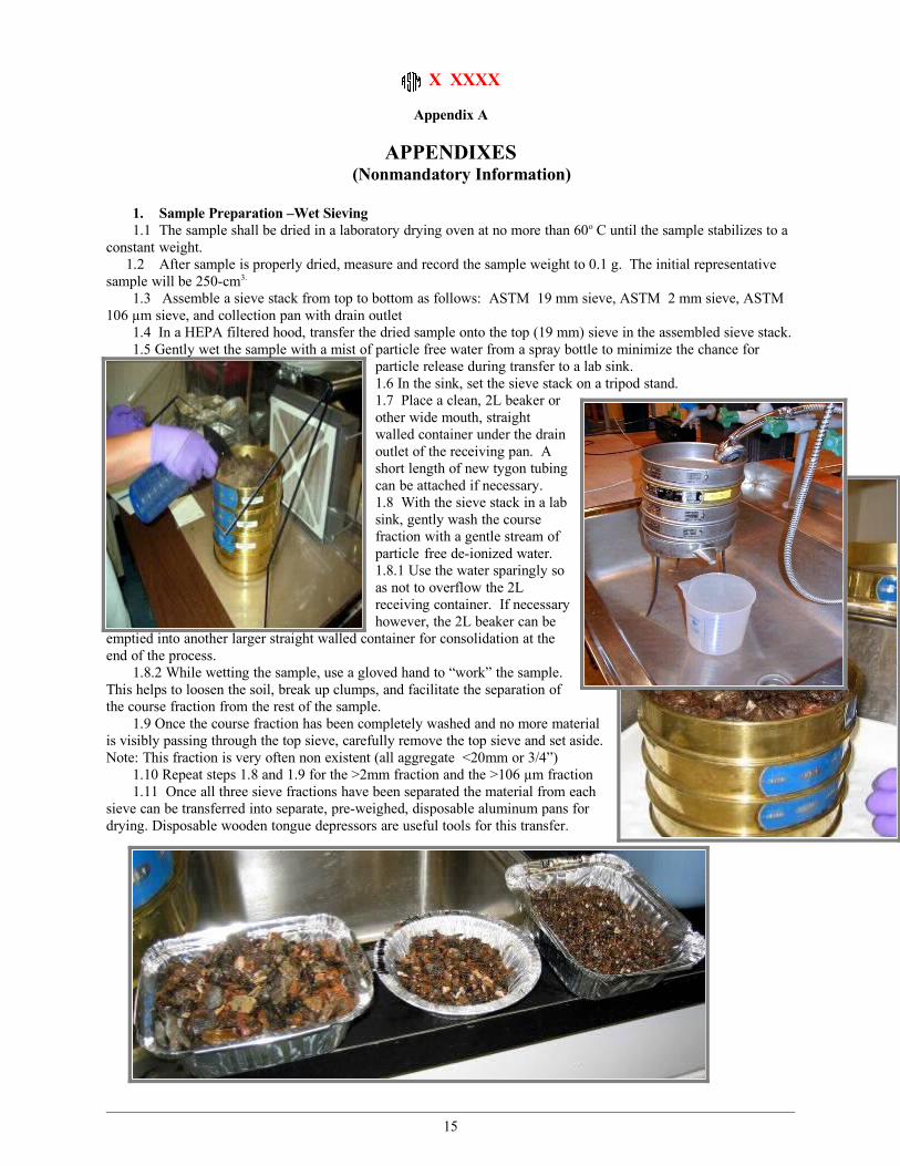
1. Sample Preparation –Wet Sieving1.1 The sample shall be dried in a laboratory drying oven at no more than 60o C until the sample stabilizes to a
constant weight.1.2 After sample is properly dried, measure and record the sample weight to 0.1 g. The initial representative
sample will be 250-cm3.
1.3 Assemble a sieve stack from top to bottom as follows: ASTM 19 mm sieve, ASTM 2 mm sieve, ASTM 106 µm sieve, and collection pan with drain outlet
1.4 In a HEPA filtered hood, transfer the dried sample onto the top (19 mm) sieve in the assembled sieve stack.1.5 Gently wet the sample with a mist of particle free water from a spray bottle to minimize the chance for
particle release during transfer to a lab sink. 1.6 In the sink, set the sieve stack on a tripod stand. 1.7 Place a clean, 2L beaker or other wide mouth, straight walled container under the drain outlet of the receiving pan. A short length of new tygon tubing can be attached if necessary.1.8 With the sieve stack in a lab sink, gently wash the course fraction with a gentle stream of particle free de-ionized water. 1.8.1 Use the water sparingly so as not to overflow the 2L receiving container. If necessary however, the 2L beaker can be
emptied into another larger straight walled container for consolidation at the end of the process.
1.8.2 While wetting the sample, use a gloved hand to “work” the sample. This helps to loosen the soil, break up clumps, and facilitate the separation of the course fraction from the rest of the sample.
1.9 Once the course fraction has been completely washed and no more material is visibly passing through the top sieve, carefully remove the top sieve and set aside. Note: This fraction is very often non existent (all aggregate <20mm or 3/4”)
1.10 Repeat steps 1.8 and 1.9 for the >2mm fraction and the >106 µm fraction1.11 Once all three sieve fractions have been separated the material from each
sieve can be transferred into separate, pre-weighed, disposable aluminum pans for drying. Disposable wooden tongue depressors are useful tools for this transfer.
15
X XXXX
1.12 Dry all three fractions following the drying procedure above.1.13 Weigh each fraction and record in g1.14 The finest fraction (<106 µm) that is in suspension in the 2L (or larger) straight walled
container, is covered and set aside for at least 12 hours to allow the particulate to settle out.1.15 The supernatant can then be decanted or aspirated off to be discarded or to be filtered and analyzed by
TEM as the “super fine” fraction.
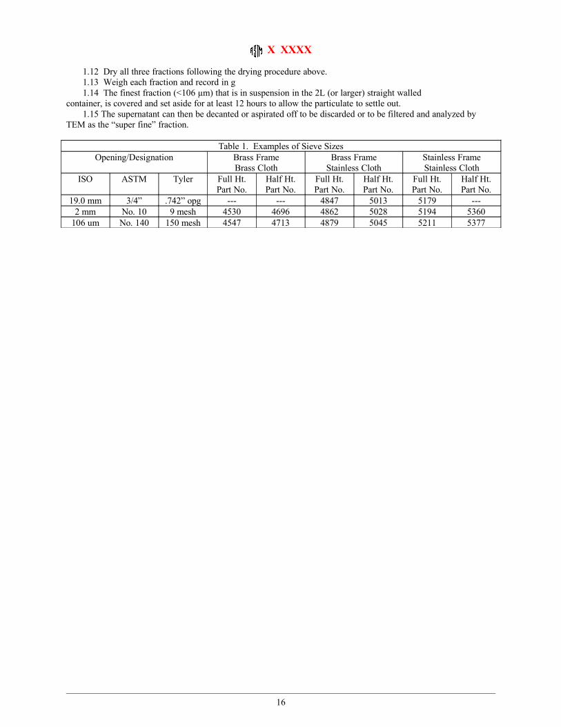
Table 1. Examples of Sieve SizesOpening/Designation Brass Frame
Brass ClothBrass Frame
Stainless ClothStainless FrameStainless Cloth
ISO ASTM Tyler Full Ht. Part No.
Half Ht. Part No.
Full Ht. Part No.
Half Ht. Part No.
Full Ht. Part No.
Half Ht. Part No.
19.0 mm 3/4” .742” opg --- --- 4847 5013 5179 ---2 mm No. 10 9 mesh 4530 4696 4862 5028 5194 5360
106 um No. 140 150 mesh 4547 4713 4879 5045 5211 5377
16


![Kinetics of thermal decomposition: calculating the ...€¦ · Method: ISO 11358-2:2014(E) standard method for the determination of activation energies [1] Instrument: SetaramSetsys](https://img.pdfslide.us/doc/110x75/607d15f40222df277336dc98/kinetics-of-thermal-decomposition-calculating-the-method-iso-11358-22014e.jpg)

![Effect of filtration coefficient determination method on ...usir.salford.ac.uk/43360/8/EFFECT OF FILTRATION COEFFICIENT DETERMINATION METHOD...standard [6] and [7] were adopted. The](https://img.pdfslide.us/doc/110x75/5e81c5ef767cf94b2f52121b/effect-of-filtration-coefficient-determination-method-on-usir-of-filtration.jpg)