Embed Size (px)
Citation preview
Designation: D 2699 – 04
Designation: 237/87
An American National Standard
Standard Test Method forResearch Octane Number of Spark-Ignition Engine Fuel 1
This standard is issued under the fixed designation D 2699; the number immediately following the designation indicates the year oforiginal adoption or, in the case of revision, the year of last revision. A number in parentheses indicates the year of last reapproval. Asuperscript epsilon (e) indicates an editorial change since the last revision or reapproval.
This standard has been approved for use by agencies of the Department of Defense.
1. Scope*
1.1 This laboratory test method covers the quantitativedetermination of the knock rating of liquid spark-ignitionengine fuel in terms of Research O.N., except that this testmethod may not be applicable to fuel and fuel components thatare primarily oxygenates.2 The sample fuel is tested using astandardized single cylinder, four-stroke cycle, variable com-pression ratio, carbureted, CFR engine run in accordance witha defined set of operating conditions. The O.N. scale is definedby the volumetric composition of PRF blends. The sample fuelknock intensity is compared to that of one or more PRF blends.The O.N. of the PRF blend that matches the K.I. of the samplefuel establishes the Research O.N.
1.2 The O.N. scale covers the range from 0 to 120 octanenumber but this test method has a working range from 40 to120 Research O.N. Typical commercial fuels produced forspark-ignition engines rate in the 88 to 101 Research O.N.range. Testing of gasoline blend stocks or other process streammaterials can produce ratings at various levels throughout theResearch O.N. range.
1.3 The values of operating conditions are stated in SI unitsand are considered standard. The values in parentheses are thehistorical inch-pound units. The standardized CFR enginemeasurements continue to be in inch-pound units only becauseof the extensive and expensive tooling that has been created forthis equipment.
1.4 This standard does not purport to address all of thesafety concerns, if any, associated with its use. It is theresponsibility of the user of this standard to establish appro-priate safety and health practices and determine the applica-bility of regulatory limitations prior to use.For specific hazard
statements, see Section 8, 13.4.1, 14.5.1, 15.6.1, Annex A1,A2.3.9, A2.4.8, A3.2.7.2(7), A4.2.3.1, A4.2.3.3(6) and (9),A4.3.5, X2.3.7, X3.2.3.1, X3.3.4.1, X3.3.9.3, X3.3.11.4, andX3.5.1.8.
2. Referenced Documents
2.1 ASTM Standards:3
D 1193 Specification for Reagent WaterD 1744 Test Method for Determination of Water in Liquid
Petroleum Products by Karl Fischer Reagent4
D 2268 Test Method for Analysis of High-Purityn-Heptaneand Isooctane by Capillary Gas Chromatography
D 2360 Test Method for Trace Impurities in MonocyclicAromatic Hydrocarbons by Gas Chromatography
D 2700 Test Method for Motor Octane Number of Spark-Ignition Engine Fuel
D 2885 Test Method for Determination of Octane Numberof Spark-Ignition Engine Fuels by On-Line Direct Com-parison Technique
D 3703 Test Method for Peroxide Number of AviationTurbine Fuels
D 4057 Practice for Manual Sampling of Petroleum andPetroleum Products
D 4175 Terminology Relating to Petroleum, PetroleumProducts, and Lubricants
D 4177 Practice for Automatic Sampling of Petroleum andPetroleum Products
D 4814 Specification for Automotive Spark-Ignition EngineFuel
D 5842 Practice for Sampling and Handling of Fuels forVolatility Measurements
E 1 Specification for Liquid-in-Glass ASTM ThermometersE 456 Terminology for Relating to Quality and Statistics
1 This test method is under the jurisdiction of ASTM Committee D02 onPetroleum Products and Lubricants and is the direct responsibility of SubcommitteeD02.01 on Combustion Characteristics.
Current edition approved May 1, 2004. Published June 2004. Originallyapproved in 1968. Last previous edition approved in 2003 as D 2699–03a.
2 Motor O.N., determined using Test Method D 2700, is a companion method toprovide a similar but typically lower octane rating under more severe operatingconditions.
3 For referenced ASTM standards, visit the ASTM website, www.astm.org, orcontact ASTM Customer Service at [email protected]. ForAnnual Book of ASTMStandardsvolume information, refer to the standard’s Document Summary page onthe ASTM website.
4 Withdrawn.
1
*A Summary of Changes section appears at the end of this standard.
Copyright © ASTM International, 100 Barr Harbor Drive, PO Box C700, West Conshohocken, PA 19428-2959, United States.

E 542 Practice for Calibration of Laboratory VolumetricApparatus
2.2 ANSI Standard:5
C-39.1 Requirements for Electrical Analog Indicating In-struments
2.3 Energy Institute Standard:IP 224/02 Determination of Low Lead Content of Light
Petroleum Distillates by Dithizone Extraction and Colo-rimetric Method6
3. Terminology
3.1 Definitions:3.1.1 accepted reference value, n—a value that serves as an
agreed-upon reference for comparison, and which is derivedas: (1) a theoretical or established value, based on scientificprinciples, (2) an assigned or certified value, based on experi-mental work of some national or international organization, or(3) a consensus or certified value, based on collaborativeexperimental work under the auspices of a scientific orengineering group. E 456
3.1.1.1 Discussion—In the context of this test method,accepted reference value is understood to apply to the Researchoctane number of specific reference materials determinedempirically under reproducibility conditions by the NationalExchange Group or another recognized exchange testing orga-nization.
3.1.2 Check Fuel, n—for quality control testing, a spark-ignition engine fuels of selected characteristics having anoctane number accepted reference value (O.N.ARV) determinedby round-robin testing under reproducibility conditions.
3.1.3 cylinder height, n—for the CFR engine, the relativevertical position of the engine cylinder with respect to thepiston at top dead center (tdc) or the top machined surface ofthe crankcase.
3.1.3.1 dial indicator reading, n—for the CFR engine, anumerical indication of cylinder height, in thousandths of aninch, indexed to a basic setting at a prescribed compressionpressure when the engine is motored.
3.1.3.2 digital counter reading, n—for the CFR engine, anumerical indication of cylinder height, indexed to a basicsetting at a prescribed compression pressure when the engine ismotored.
3.1.4 detonation meter, n—for knock testing, the signalconditioning instrumentation that accepts the electrical signalfrom the detonation pickup and provides an output signal fordisplay.
3.1.5 detonation pickup, n—for knock testing, amagnetostrictive-type transducer that threads into the enginecylinder and is exposed to combustion chamber pressure toprovide an electrical signal that is proportional to the rate-of-change of cylinder pressure.
3.1.6 dynamic fuel level, n—for knock testing, test proce-dure in which the fuel-air ratio for maximum knock intensity
for sample and reference fuels is determined using the fallinglevel technique that changes carburetor fuel level from a highor rich mixture condition to a low or lean mixture condition, ata constant rate, causing knock intensity to rise to a maximumand then decrease, thus permitting observation of the maxi-mum knockmeter reading.
3.1.7 equilibrium fuel level, n—for knock testing, test pro-cedure in which the fuel-air ratio for maximum knock intensityfor sample and reference fuels is determined by makingincremental step changes in carburetor fuel level, observing theequilibrium knock intensity for each step, and selecting thelevel that produces the highest knock intensity reading.
3.1.8 firing, n—for the CFR engine, operation of the CFRengine with fuel and ignition.
3.1.9 fuel-air ratio for maximum knock intensity, n—forknock testing, that proportion of fuel to air that produces thehighest knock intensity for each fuel in the knock testing unit,provided this occurs within specified carburetor fuel levellimits.
3.1.10 guide tables, n—for knock testing, the specific rela-tionship between cylinder height (compression ratio) andoctane number at standard knock intensity for specific primaryreference fuel blends tested at standard or other specifiedbarometric pressure.
3.1.11 knock, n—in a spark-ignition engine, abnormal com-bustion, often producing audible sound, caused by autoignitionof the air/fuel mixture. D 4175
3.1.12 knock intensity, n—for knock testing, a measure ofthe level of knock.
3.1.13 knockmeter, n—for knock testing, the 0 to 100division indicating meter that displays the knock intensitysignal from the detonation meter.
3.1.14 motoring, n—for the CFR engine, operation of theCFR engine without fuel and with the ignition shut off.
3.1.15 octane number, n—for spark-ignition engine fuel,any one of several numerical indicators of resistance to knockobtained by comparison with reference fuels in standardizedengine or vehicle tests. D 4175
3.1.15.1 research octane number, n—for spark-ignition en-gine fuel, the numerical rating of knock resistance obtained bycomparison of its knock intensity with that of primary refer-ence fuel blends when both are tested in a standardized CFRengine operating under the conditions specified in this testmethod.
3.1.16 oxygenate, n—an oxygen-containing organic com-pound, which may be used as a fuel or fuel supplement, forexample, various alcohols and ethers. D 4175
3.1.17 primary reference fuels, n—for knock testing, isooc-tane,n-heptane, volumetrically proportioned mixtures ofisooc-tane withn-heptane, or blends of tetraethyllead inisooctanethat define the octane number scale.
3.1.17.1primary reference fuel blends below 100 octane,n—the volume % ofisooctane in a blend withn-heptane thatdefines the octane number of the blend,isooctane beingassigned as 100 andn-heptane as 0 octane number.
3.1.17.2primary reference fuel blends above 100 octane,n—the millilitres per U.S. gallon of tetraethyllead inisooctane
5 Available from American National Standards Institute (ANSI), 25 W. 43rd St.,4th Floor, New York, NY 10036.
6 Available from Energy Institute, 61 New Cavendish St., London, WIG 7AR,U.K.
D 2699 – 04
2

that define octane numbers above 100 in accordance with anempirically determined relationship.
3.1.18 repeatability conditions, n—conditions where inde-pendent test results are obtained with the same method onidentical test items in the same laboratory by the same operatorusing the same equipment within short intervals of time.
E 4563.1.18.1Discussion—In the context of this test method, a
short time interval between two ratings on a sample fuel isunderstood to be not less than the time to obtain at least onerating on another sample fuel between them but not so long asto permit any significant change in the sample fuel, testequipment, or environment.
3.1.19 reproducibility conditions, n—conditions where testresults are obtained with the same method on identical testitems in different laboratories with different operators usingdifferent equipment. E 456
3.1.20 spread, n—in knock measurement, the sensitivity ofthe detonation meter expressed in knockmeter divisions peroctane number.
3.1.21 standard knock intensity, n—for knock testing, thatlevel of knock established when a primary reference fuel blendof specific octane number is used in the knock testing unit atmaximum knock intensity fuel-air ratio, with the cylinderheight (dial indicator or digital counter reading) set to theprescribed guide table value. The detonation meter is adjustedto produce a knockmeter reading of 50 for these conditions.
3.1.22 toluene standardization fuels, n—for knock testing,those volumetrically proportioned blends of two or more of thefollowing: reference fuel grade toluene,n-heptane, andisooc-tane that have prescribed rating tolerances for O.N.ARV deter-mined by round-robin testing under reproducibility conditions.
3.2 Abbreviations:3.2.1 ARV= accepted reference value3.2.2 C.R.= compression ratio3.2.3 IAT = intake air temperature3.2.4 K.I. = knock intensity3.2.5 O.N.= octane number3.2.6 PRF= primary reference fuel3.2.7 TSF= toluene standardization fuel
4. Summary of Test Method
4.1 The Research O.N. of a spark-ignition engine fuel isdetermined using a standard test engine and operating condi-tions to compare its knock characteristic with those of PRFblends of known O.N. Compression ratio and fuel-air ratio areadjusted to produce standard K.I. for the sample fuel, asmeasured by a specific electronic detonation meter instrumentsystem. A standard K.I. guide table relates engine C.R. to O.N.level for this specific method. The fuel-air ratio for the samplefuel and each of the primary reference fuel blends is adjustedto maximize K.I. for each fuel.
4.1.1 The fuel-air ratio for maximum K.I. may be obtained(1) by making incremental step changes in mixture strength,observing the equilibrium K.I. value for each step, and thenselecting the condition that maximizes the reading or (2) bypicking the maximum K.I. as the mixture strength is changedfrom either rich-to-lean or lean-to-rich at a constant rate.
4.2 Bracketing Procedures—The engine is calibrated tooperate at standard K.I. in accordance with the guide table. Thefuel-air ratio of the sample fuel is adjusted to maximize theK.I., and then the cylinder height is adjusted so that standardK.I. is achieved. Without changing cylinder height, two PRFblends are selected such that, at their fuel-air ratio for maxi-mum K.I., one knocks harder (higher K.I.) and the other softer(lower K.I.) than the sample fuel. A second set of K.I.measurements for sample fuel and PRF blends is required, andthe sample fuel octane number is calculated by interpolation inproportion to the differences in average K.I. readings. A finalcondition requires that the cylinder height used shall be withinprescribed limits around the guide table value for the calculatedO.N. Bracketing procedure ratings may be determined usingeither the equilibrium fuel level or dynamic fuel level fuel-airratio approach.
4.3 C.R. Procedure—A calibration is performed to establishstandard K.I. using the cylinder height specified by the guidetable for the O.N. of the selected PRF. The fuel-air ratio of thesample fuel is adjusted to maximize the K.I. under equilibriumconditions; the cylinder height is adjusted so that standard K.I.is achieved. The calibration is reconfirmed and the sample fuelrating is repeated to establish the proper conditions a secondtime. The average cylinder height reading for the sample fuel,compensated for barometric pressure, is converted directly toO.N., using the guide table. A final condition for the ratingrequires that the sample fuel O.N. be within prescribed limitsaround that of the O.N. of the single PRF blend used tocalibrate the engine to the guide table standard K.I. condition.
5. Significance and Use
5.1 Research O.N. correlates with commercial automotivespark-ignition engine antiknock performance under mild con-ditions of operation.
5.2 Research O.N. is used by engine manufacturers, petro-leum refiners and marketers, and in commerce as a primaryspecification measurement related to the matching of fuels andengines.
5.2.1 Empirical correlations that permit calculation of auto-motive antiknock performance are based on the general equa-tion:
Road O.N.5 ~k1 3 Research O.N.! 1 ~k2 3 Motor O.N.! 1 k3 (1)
Values of k1, k2, and k3 vary with vehicles and vehiclepopulations and are based on road-O.N. determinations.
5.2.2 Research O.N., in conjunction with Motor O.N.,defines the antiknock index of automotive spark-ignition en-gine fuels, in accordance with Specification D 4814. Theantiknock index of a fuel approximates the Road octane ratingsfor many vehicles, is posted on retail dispensing pumps in theU.S., and is referred to in vehicle manuals.
Antiknock index5 0.5 Research O.N.1 0.5 Motor O.N.1 0 (2)
This is more commonly presented as:
Antiknock Index5~R1 M!
2 (3)
5.2.3 Research O.N. is also used either alone or in conjunc-tion with other factors to define the Road O.N. capabilities of
D 2699 – 04
3
spark-ignition engine fuels for vehicles operating in areas ofthe world other than the United States.
5.3 Research O.N. is used for measuring the antiknockperformance of spark-ignition engine fuels that contain oxy-genates.
5.4 Research O.N. is important in relation to the specifica-tions for spark-ignition engine fuels used in stationary andother nonautomotive engine applications.
6. Interferences
6.1 Precaution—Avoid exposure of sample fuels to sunlightor fluorescent lamp UV emissions to minimize induced chemi-cal reactions that can affect octane number ratings.7
6.1.1 Exposure of these fuels to UV wavelengths shorterthan 550 nm for a short period of time may significantly affectoctane number ratings.
6.2 Certain gases and fumes that can be present in the areawhere the knock testing unit is located may have a measurableeffect on the Research O.N. test result.
6.2.1 Halogenated refrigerant used in air conditioning andrefrigeration equipment can promote knock. Halogenated sol-vents can have the same effect. If vapors from these materialsenter the combustion chamber of the CFR engine, the ResearchO.N. obtained for sample fuels can be depreciated.
6.3 Electrical power subject to transient voltage or fre-quency surges or distortion can alter CFR engine operatingconditions or knock measuring instrumentation performanceand thus affect the Research O.N. obtained for sample fuels.
7. Apparatus
7.1 Engine Equipment8—This test method uses a singlecylinder, CFR engine that consists of standard components asfollows: crankcase, a cylinder/clamping sleeve assembly toprovide continuously variable compression ratio adjustablewith the engine operating, a thermal syphon recirculatingjacket coolant system, a multiple fuel tank system with selectorvalving to deliver fuel through a single jet passage andcarburetor venturi, an intake air system with controlled tem-perature and humidity equipment, electrical controls, and asuitable exhaust pipe. The engine flywheel is belt connected toa special electric power-absorption motor utilized to both startthe engine and as a means to absorb power at constant speedwhen combustion is occurring (engine firing). See Fig. 1.
7.1.1 See Annex A2 for details and description of all critical,non-critical, and equivalent engine equipment.
7.2 Instrumentation8—This test method uses electronicdetonation metering instrumentation to measure the intensity ofcombustion knock as well as conventional thermometry, gages,and general purpose meters.
7.2.1 See Annex A3 for details and description of all critical,non-critical, and equivalent instrumentation.
7.3 Reference and Standardization Fuel DispensingEquipment—This test method requires repeated blending ofreference fuels and TSF materials in volumetric proportions. Inaddition, blending of dilute tetraethyllead inisooctane may beperformed on-site for making rating determinations above 100O.N. Blending shall be performed accurately because ratingerror is proportional to blending error.
7.3.1 Volumetric Blending of Reference Fuels—Volumetricblending has historically been employed to prepare the re-quired blends of reference fuels and TSF materials. Forvolumetric blending, a set of burets, or accurate volumetricapparatus, shall be used and the desired batch quantity shall becollected in an appropriate container and thoroughly mixedbefore being introduced to the engine fuel system.
7.3.1.1 Calibrated burets or volumetric apparatus having acapacity of 200 to 500 mL and a maximum volumetrictolerance of60.2 % shall be used for preparation of referenceand standardization fuel blends. Calibration shall be verified inaccordance with Practice E 542.
7.3.1.2 Calibrated burets shall be outfitted with a dispensingvalve and delivery tip to accurately control dispensed volume.The delivery tip shall be of such design that shut-off tipdischarge does not exceed 0.5 mL.
7.3.1.3 The rate of delivery from the dispensing systemshall not exceed 400 mL per 60 s.
7.3.1.4 The set of burets for the reference and standardiza-tion fuels shall be installed in such a manner and be suppliedwith fluids such that all components of each batch or blend aredispensed at the same temperature.
7.3.1.5 See Appendix X1 for volumetric reference fueldispensing system information.
7.3.2 Volumetric Blending of Tetraethyllead—A calibratedburet, pipette assembly, or other liquid dispensing apparatushaving a capacity of not more than 4.0 mL and a criticallycontrolled volumetric tolerance shall be used for dispensingdilute tetraethyllead into 400-mL batches ofisooctane. Cali-bration of the dispensing apparatus shall be verified in accor-dance with Practice E 542.
7.3.3 Gravimetric Blending of Reference Fuels—Use ofblending systems that allow preparation of the volumetrically-defined blends by gravimetric (mass) measurements based onthe density of the individual components is also permitted,provided the system meets the requirement for maximum 0.2% blending tolerance limits.
7.3.3.1 Calculate the mass equivalents of thevolumetrically-defined blend components from the densities ofthe individual components at 15.56°C (60°F).
7.4 Auxiliary Apparatus:7.4.1 Special Maintenance Tools—A number of specialty
tools and measuring instruments should be utilized for easy,convenient, and effective maintenance of the engine and testingequipment. Lists and descriptions of these tools and instru-ments are available from the manufacturer of the engineequipment and those organizations offering engineering andservice support for this test method.
7 Supporting data have been filed at ASTM International Headquarters and maybe obtained by requesting Research Report RR: D02–1502.
8 The sole source of supply of the Engine equipment and instrumentation knownto the committee at this time is Waukesha Engine, Dresser Inc., 1000 West St. PaulAve., Waukesha, WI 53188. Waukesha Engine also has CFR engine authorized salesand service organizations in selected geographical areas. If you are aware ofalternative suppliers, please provide this information to ASTM InternationalHeadquarters. Your comments will receive careful consideration at a meeting of theresponsible technical committee,1 which you may attend.
D 2699 – 04
4

7.4.2 Ventilation Hoods—Handling of reference and stan-dardization fuels, dilute tetraethyllead, and test samples havingvarious hydrocarbon compositions is best conducted in a wellventilated space or in a laboratory hood where air movementacross the area is sufficient to prevent operator inhalation ofvapors.
7.4.2.1 General purpose laboratory hoods are typically ef-fective for handling hydrocarbon fuel blending.9
7.4.2.2 A blending hood meeting the requirements for dis-pensing toxic material shall be utilized in testing laboratoriesthat choose to prepare leadedisooctane PRF blends on-site.
8. Reagents and Reference Materials
8.1 Cylinder Jacket Coolant—Water shall be used in thecylinder jacket for laboratory locations where the resultantboiling temperature shall be 1006 1.5°C (2126 3°F). Waterwith commercial glycol-based antifreeze added in sufficientquantity to meet the boiling temperature requirement shall beused when laboratory altitude dictates. A commercial multi-functional water treatment material should be used in the
9 Refer toIndustrial Ventilation Manual, published by the American Conferenceof Governmental Industrial Hygienists, Cincinnati, OH.
A—Air humidifier tubeB—Intake air heaterC—Coolant condenserD—Four bowl carburetorE—C.R. change motorF—CFR-48 crankcaseG—Oil FilterH—Ignition Detonation meterJ—KnockmeterK—C.R. digital counter
FIG. 1 Research Method Test Engine Assembly
D 2699 – 04
5

coolant to minimize corrosion and mineral scale that can alterheat transfer and rating results. (Warning—Ethylene glycolbased antifreeze is poisonous and may be harmful or fatal ifinhaled or swallowed. See Annex A1.)
8.1.1 Water shall be understood to mean reagent waterconforming to Type IV, of Specification D 1193.
8.2 Engine Crankcase Lubricating Oil—An SAE 30 viscos-ity grade oil meeting the current API service classification forspark-ignition engines shall be used. It shall contain a detergentadditive and have a kinematic viscosity of 9.3 to 12.5 mm2 pers (cSt) at 100°C (212°F) and a viscosity index of not less than85. Oils containing viscosity index improvers shall not be used.Multigraded oils shall not be used. (Warning—Lubricating oilis combustible and its vapor is harmful. See Annex A1.)
8.3 PRF,10 isooctane and normal heptane classified as ref-erence fuel grade and meeting the specifications that follow:(Warning—Primary reference fuel is flammable and its vaporsare harmful. Vapors may cause flash fire. See Annex A1.)
8.3.1 Isooctane(2,2,4-trimethylpentane) shall be no lessthan 99.75 % by volume pure, contain no more than 0.10 % byvolumen-heptane, and contain no more than 0.5 mg/L (0.002g/U.S. gal) of lead.11 (Warning—Isooctane is flammable andits vapors are harmful. Vapors may cause flash fire. See AnnexA1.)
8.3.2 n-heptaneshall be no less than 99.75 % by volumepure, contain no more than 0.10 % by volumeisooctane andcontain no more than 0.5 mg/L (0.002 g/U.S. gal) of lead.11
(Warning—n-heptane is flammable and its vapors are harmful.Vapors may cause flash fire. See Annex A1.)
8.3.3 80 octane PRF blend,12 prepared using reference fuelgrade isooctane andn-heptane shall contain 806 0.1 % byvolume isooctane.13 (Warning—80 octane PRF is flammableand its vapors are harmful. Vapors may cause flash fire. SeeAnnex A1.)
8.3.4 Refer to Annex A5 for octane numbers of variousblends of 80 octane PRF and eithern-heptane orisooctane(Table A5.2).
8.4 Dilute Tetraethyllead14 (Commonly referred to as TELDilute Volume Basis) is a prepared solution of aviation mixtetraethyllead antiknock compound in a hydrocarbon diluent of70 % (V/V) xylene, 30 % (V/V)n-heptane. (Warning—Dilutetetraethyllead is poisonous and flammable. It may be harmfulor fatal if inhaled, swallowed, or absorbed through the skin.May cause flash fire. See Annex A1.)
8.4.1 The fluid shall contain 18.236 0.05 % (m/m) tetra-ethyllead and have a relative density 15.6/15.6°C (60/60°F) of
0.957 to 0.967. The typical composition of the fluid, excludingthe tetraethyllead, is as follows:
IngredientTypical Concentration,
% (m/m)Ethylene dibromide (scavenger) 10.6Diluent:
xylene 52.5n-heptane 17.8
Dye, antioxidant and inerts 0.87
8.4.2 Add dilute tetraethyllead, in millilitre quantities, to a400-mL volume ofisooctane to prepare PRF blends used forratings over 100 O.N. The composition of the dilute fluid issuch that when 2.0 mL are added to 400 mL ofisooctane, theblend shall contain the equivalent of 2.0 mL of lead/U.S. gal(0.56 g of lead/L).8,15
8.4.3 Refer to Annex A5 for octane numbers of blends oftetraethyllead andisooctane (see Table A5.3).
8.5 Toluene, Reference Fuel Grade8,16 shall be no less than99.5 % by volume pure. Peroxide number shall not exceed 5mg per kg (ppm). Water content shall not exceed 200 mg perkg.17 (Warning—Toluene is flammable and its vapors areharmful. Vapors may cause flash fire. See Annex A1.)
8.5.1 Antioxidant shall be added by the supplier at a treatrate suitable for good long term stability as empiricallydetermined with the assistance of the antioxidant supplier.
8.6 Check Fuels are in-house typical spark-ignition enginefuels having selected octane numbers, low volatility, and goodlong term stability. (Warning—Check Fuel is flammable andits vapors are harmful. Vapors may cause flash fire. See AnnexA1.)
9. Sampling
9.1 Collect samples in accordance with Practices D 4057,D 4177, or D 5842.
9.2 Sample Temperature—Samples shall be cooled to atemperature of 2 to 10°C (35 to 50°F), in the container in whichthey are received, before the container is opened.
9.3 Protection from Light—Collect and store sample fuelsin an opaque container, such as a dark brown glass bottle, metalcan, or a minimally reactive plastic container to minimizeexposure to UV emissions from sources such as sunlight orfluorescent lamps.
10. Basic Engine and Instrument Settings and StandardOperating Conditions
10.1 Installation of Engine Equipment andInstrumentation—Installation of the engine and instrumenta-tion requires placement of the engine on a suitable foundationand hook-up of all utilities. Engineering and technical support
10 Primary Reference Fuels are currently available from Chevron PhillipsChemical Company LP., 1301 McKinney, Suite 2130, Houston, TX 77010–3030 orHaltermann Gmbh, Schopenstehl 15, 20095, Hamburg, Germany.
11 Hydrocarbon composition shall be determined in accordance with Test MethodD 2268. Lead contamination shall be determined in accordance with IP 224/02.
12 80 O.N. PRF are currently available from Chevron Phillips ChemicalCompany LP., 1301 McKinney, Suite 2130, Houston, TX 77010–3030 or Halter-mann Gmbh, Schopenstehl 15, 20095, Hamburg, Germany.
13 The supplier verifies that the blend contains by volume, 80 %isooctane, 20 %n-heptane using capillary gas chromatography and analytical calculations.
14 Dilute tetraethyllead is available from Ethyl Corporation, 330 South FourthStreet, Richmond, VA 23219-4304; or from The Associated Octel Company, Ltd., 23Berkeley Square, London, England W1X 6DT.
15 The sole source of supply of remixed PRF blends ofisooctane containingspecific amounts of tetraethyllead known to the committee at this time is ChevronPhillips Chemical Company LP., 1301 McKinney, Suite 2130, Houston, TX77010–3030.
16 The sole source of supply of Toluene, reference fuel grade known to thecommittee at this time is Chevron Phillips Chemical Company LP., 1301 McKinney,Suite 2130, Houston, TX 77010–3030.
17 Toluene purity is determined by subtracting the sum of the hydrocarbonimpurities and water content from 100 %. Determine the hydrocarbon impurities byTest Method D 2360. Determine water content by Test Method D 1744. Peroxidenumber shall be determined in accordance with Test Method D 3703.
D 2699 – 04
6

for this function is required, and the user shall be responsibleto comply with all local and national codes and installationrequirements.
10.1.1 Proper operation of the CFR engine requires assem-bly of a number of engine components and adjustment of aseries of engine variables to prescribed specifications. Some ofthese settings are established by component specifications,others are established at the time of engine assembly or afteroverhaul, and still others are engine running conditions thatmust be observed or determined by the operator during thetesting process.
10.2 Conditions Based on Component Specifications:10.2.1 Engine Speed—600 6 6 rpm, when the engine is
firing, with a maximum variation of 6 rpm occurring during arating. Engine speed, while firing, shall not be more than 3 rpmgreater than when it is motoring without combustion.
10.2.2 Indexing Flywheel to Top-Dead-Center (tdc)—Withthe piston at the highest point of travel in the cylinder, set theflywheel pointer mark in alignment with the 0° mark on theflywheel in accordance with the instructions of the manufac-turer.
10.2.3 Valve Timing—The engine uses a four-stroke cyclewith two crankshaft revolutions for each complete combustioncycle. The two critical valve events are those that occur neartdc; intake valve opening and exhaust valve closing. See AnnexA4 for camshaft timing and valve lift measurement procedures.
10.2.3.1 Intake valve opening shall occur 10.06 2.5°after-top-dead-center (atdc) with closing at 34° after-bottom-dead-center (abdc) on one revolution of the crankshaft andflywheel.
10.2.3.2 Exhaust valve opening shall occur 40° before-bottom-dead-center (bbdc) on the second revolution of thecrankshaft and flywheel, with closing at 15.06 2.5° atdc onthe next revolution of the crankshaft and flywheel.
10.2.4 Valve Lift—Intake and exhaust cam lobe contours,while different in shape, shall have a contour rise of 0.246 to0.250 in. (6.248 to 6.350 mm) from the base circle to the topof the lobe. The resulting valve lift shall be 0.2386 0.002 in.(6.0456 0.05 mm). See Annex A4 for camshaft timing andvalve lift measurement procedure.
10.2.5 Intake Valve Shroud—The intake valve has a 180°shroud or protrusion just inside the valve face to direct theincoming fuel-air charge and increase the turbulence within thecombustion chamber. This valve stem is drilled for a pin, whichis restrained in a valve guide slot, to prevent the valve fromrotating and thus maintain the direction of swirl. The valveshall be assembled in the cylinder, with the pin aligned in thevalve guide, so that the shroud is toward the spark plug side ofthe combustion chamber and the swirl is directed in a coun-terclockwise direction if it could be observed from the top ofthe cylinder.
10.2.6 Carburetor Venturi—A 9⁄16-in. (14.3-mm) venturithroat size shall be used regardless of ambient barometricpressure.
10.3 Assembly Settings and Operating Conditions:10.3.1 Direction of Engine Rotation—Clockwise rotation of
the crankshaft when observed from the front of the engine.10.3.2 Valve Clearances:
10.3.2.1Engine Stopped and Cold—Clearance between thevalve stem and valve rocker half-ball, set upon assemblybefore the engine is operated can provide the controllingengine running and hot clearance. With the engine at tdc on thecompression stroke, the appropriate cold clearances are asfollows:
Intake Valve 0.004 in. (0.102 mm)Exhaust Valve 0.014 in. (0.356 mm)
These clearances should ensure that both valves have suffi-cient clearance to cause valve seating during engine warmup.The adjustable-length valve push-rods shall be set so that thevalve rocker adjusting screws have adequate travel to permitthe final clearance setting.
10.3.2.2Engine Running and Hot—The clearance for bothintake and exhaust valves shall be set to 0.0086 0.001 in.(0.20 6 0.025 mm), measured under standard operatingconditions with the engine running at equilibrium conditionson a 90-O.N. PRF blend.
10.3.3 Oil Pressure—172 to 207 kPa (25 to 30 psi). SeeAnnex A4 for the procedure to adjust crankcase lubricating oilpressure.
10.3.4 Oil Temperature—57 6 8°C (1356 15°F).10.3.5 Cylinder Jacket Coolant Temperature—1006 1.5°C
(212 6 3°F) constant within60.5°C (61°F) during a rating.10.3.6 Intake Air Temperature—52 6 1°C (1256 2°F) is
specified for operation at standard barometric pressure of 101.0kPa (29.92 in. Hg). IATs for other prevailing barometricpressure conditions are listed in Annex A6 (see Tables A6.4 andA6.5). If IAT tuning is used to qualify the engine as fit-for-use,the temperature selected shall be within622°C (640°F) of thetemperature listed in Annex A6 (Tables A6.4 and A6.5) for theprevailing barometric pressure and this temperature shall thenbe maintained within61°C (62°F) during a rating.
10.3.6.1 The IAT required to qualify the engine in each TSFblend O.N. range shall also be used for rating all sample fuelsin that O.N. range during an operating period.
10.3.7 Intake Air Humidity—0.00356 to 0.00712 kg waterper kg (25 to 50 grains of water per lb) of dry air.
10.3.8 Cylinder Jacket Coolant Level:10.3.8.1Engine Stopped and Cold—Treated water/coolant
added to the cooling condenser-cylinder jacket to a level justobservable in the bottom of the condenser sight glass willtypically provide the controlling engine running and hotoperating level.
10.3.8.2Engine Running and Hot—Coolant level in thecondenser sight glass shall be within61 cm (60.4 in.) of theLEVEL HOT mark on the coolant condenser.
10.3.9 Engine Crankcase Lubricating Oil Level:10.3.9.1Engine Stopped and Cold—Oil added to the crank-
case so that the level is near the top of the sight glass willtypically provide the controlling engine running and hotoperating level.
10.3.9.2Engine Running and Hot—Oil level shall be ap-proximately mid-position in the crankcase oil sight glass.
10.3.10 Crankcase Internal Pressure—As measured by agage or manometer connected to an opening to the inside of thecrankcase through a snubber orifice to minimize pulsations, thepressure shall be less than zero (a vacuum) and is typically
D 2699 – 04
7
from 25 to 150 mm (1 to 6 in.) of water less than atmosphericpressure. Vacuum shall not exceed 255 mm (10 in.) of water.
10.3.11 Exhaust Back Pressure—As measured by a gage ormanometer connected to an opening in the exhaust surge tankor main exhaust stack through a snubber orifice to minimizepulsations, the static pressure should be as low as possible, butshall not create a vacuum nor exceed 255 mm (10 in.) of waterdifferential in excess of atmospheric pressure.
10.3.12 Exhaust and Crankcase Breather SystemResonance—The exhaust and crankcase breather piping sys-tems shall have internal volumes and be of such length that gasresonance does not result. See Appendix X2 for a suitableprocedure to determine if resonance exists.
10.3.13 Belt Tension—The belts connecting the flywheel tothe absorption motor shall be tightened, after an initial break-in, so that with the engine stopped, a 2.25-kg (5-lb) weightsuspended from one belt halfway between the flywheel andmotor pulley shall depress the belt approximately 12.5 mm (0.5in.).
10.3.14 Basic Rocker Arm Carrier Adjustment:10.3.14.1Basic Rocker Arm Carrier Support Setting—Each
rocker arm carrier support shall be threaded into the cylinder sothat the distance between the machined surface of the cylinderand the underside of the fork is 31 mm (17⁄32 in.).
10.3.14.2Basic Rocker Arm Carrier Setting—With thecylinder positioned so that the distance between the undersideof the cylinder and the top of the clamping sleeve is approxi-mately 16 mm (5⁄8 in.), the rocker arm carrier shall be sethorizontal before tightening the bolts that fasten the longcarrier support to the clamping sleeve.
10.3.14.3Basic Rocker Arm Setting—With the engine ontdc on the compression stroke, and the rocker arm carrier set atthe basic setting, set the valve adjusting screw to approxi-mately the mid-position in each rocker arm. Then adjust thelength of the push rods so that the rocker arms shall be in thehorizontal position.
10.3.15 Basic Spark Setting—13° btdc regardless of cylin-der height.
10.3.15.1 The digital timing indicator currently suppliedwith CFR engine units, or the graduated spark quadrantformerly supplied, shall be in proper working order andcalibrated so that the time of ignition is correctly displayedwith reference to the engine crankshaft.
10.3.15.2Basic Ignition Timer Control Arm Setting—If theCFR engine is equipped with an ignition control arm assembly,the knurled clamping screw on the control arm shall be looseso that the linkage is ineffective.
10.3.15.3Ignition Timer Basic Transducer to Rotor VaneGap Setting—0.08 to 0.13 mm (0.003 to 0.005 in.).
10.3.16 Spark Plug Gap—0.516 0.13 mm (0.0206 0.005in.).
10.3.17 Basic Cylinder Height Setting—Thoroughly warmup the engine under essentially standard operating conditions.Shut the unit down and check that the ignition is turned off andfuel cannot enter the combustion chamber. Install a calibratedcompression pressure gage assembly on the engine, motor theengine, and adjust the cylinder height so that the unit producesthe basic compression pressure for the prevailing barometricpressure as prescribed by the relationship of Fig. 2.
FIG. 2 Actual Compression Pressure for Setting Cylinder Height
D 2699 – 04
8
10.3.17.1 Index the cylinder height measurement device(s)to the appropriate value, uncompensated for barometric pres-sure, as follows:
Digital Counter Reading of 930Dial Indicator Reading of 0.352 in.
10.3.17.2 Refer to Annex A4 for a detailed cylinder heightindexing procedure.
10.3.18 Fuel-Air Ratio—The fuel-air ratio (mixture propor-tion) for each sample fuel and PRF involved in the determina-tion of an O.N. result shall be that which maximizes the K.I.
10.3.18.1 Fuel-air ratio is a function of the effective fuellevel in the vertical jet of the standard carburetor assembly andis typically indicated as the fuel level in the appropriatecarburetor sight glass.
10.3.18.2 The fuel level that produces maximum K.I. shallbe from 0.7 to 1.7 in., referenced to the centerline of theventuri. If necessary, change the carburetor horizontal jet size(or equivalent restrictive orifice device) to satisfy the fuel levelrequirement.
10.3.19 Carburetor Cooling—Circulate coolant through thecoolant passages of the carburetor whenever there is evidenceof premature vaporization in the fuel delivery passages. Re-lease of hydrocarbon vapors from the sample fuel can result inuneven engine operation or erratic K.I. reading and is usuallyindicated by bubble formation or abnormal fluctuation of thefuel level in the sight glass.
10.3.19.1Coolant—Water or a water/antifreeze mixture.10.3.19.2Coolant Temperature—The liquid coolant deliv-
ered to the carburetor coolant exchangers shall be cold enoughto prevent excessive vaporization but not colder than 0.6°C(33°F) or warmer than 10°C (50°F).18
10.3.20 Instrumentation:10.3.20.1Knockmeter Reading Limits—The operational
range for K.I. readings on the knockmeter shall be from 20 to80. Knock intensity is a nonlinear characteristic below 20 andthe knockmeter has the potential to be nonlinear above 80.
10.3.20.2Detonation Meter Spread and Time ConstantSettings—Optimize these variables to maximize spread com-mensurate with reasonable K.I. signal stability. Refer to Pro-cedure sections and Annex A4 for further detail.
10.3.20.3Knockmeter Needle Mechanical ZeroAdjustment—With the detonation meter power switch in theOFF position, and the meter switch in the ZERO position, setthe knockmeter needle to ZERO using the adjusting screwprovided on the knockmeter face.
10.3.20.4Detonation Meter Zero Adjustment—With thedetonation meter power switch in the ON position, the meterswitch in the ZERO position, the time constant switch on 3,and the meter reading and spread controls in their nominaloperating positions, set the needle of the knockmeter to readZERO using the detonation meter zero adjusting screw, whichis to the left of the meter switch on the detonation meter andcovered by a knurled cap.
11. Engine Standardization
11.1 Unit Preparation—Operate the properly commis-sioned knock test unit at temperature equilibrium and incompliance with the basic engine and instrument settings andstandard operating conditions prescribed for this test method.
11.1.1 Operate the engine on fuel for approximately 1 h toensure that all critical variables are stable. During the final 10min of this warm-up period, operate the engine at a typical K.I.level.
11.2 Fit-for-Use Qualification for Each Operating Period:11.2.1 Every sample fuel O.N. determination shall be per-
formed using an engine that has been qualified as fit-for-use byrating the appropriate TSF blend.
11.2.2 Qualify the engine using the appropriate TSF blendsin accordance with the following conditions:
11.2.2.1 At least once during each 12 h period of rating.11.2.2.2 After an engine has been shut down for more than
2 h.11.2.2.3 After a unit has been operated at non-knocking
conditions for more than 2 h.11.2.2.4 After a barometric pressure change of more than
0.68 kPa (0.2 in. Hg) from that reading made at the time of theprevious TSF blend rating for the specific O.N. range.
11.2.3 When either bracketing procedure is utilized todetermine the TSF blend rating, establish standard K.I. using aPRF blend whose whole O.N. is closest to that of the O.N.ARV
of the selected TSF blend.11.2.4 When either bracketing procedure is utilized to
determine the TSF blend rating, set the cylinder height,compensated for the prevailing barometric pressure, to theguide table value for the O.N.ARV of the selected TSF blend.
11.2.5 When the compression ratio procedure is utilized todetermine the TSF blend rating, first establish standard K.I.using the PRF blend whose whole O.N. is closest to that of theO.N.ARV of the selected TSF blend.
11.3 Fit-for-Use Procedure—87.3 to 100.0 O.N. Range:11.3.1 Select the appropriate TSF blend(s) from Table 1 that
are applicable for the O.N. values of the sample fuel ratingstested or to be tested during the operating period.
11.3.2 Rate the TSF blend using the standard IAT based onthe prevailing barometric pressure.
11.3.2.1 If the engine standardization during the last oper-ating period required IAT tuning to be fit-for-use and mainte-nance has not taken place, it is permissible to start fit-for-use
18 Supporting data have been filed at ASTM International Headquarters and maybe obtained by requesting Research Report RR: D02-1006.
TABLE 1 TSF Blend Octane Number Accepted Reference Values,Untuned Rating Tolerances and Sample Fuel Octane Number
Range of Use A
TSF BlendR.O.N.ARV
UntunedRating
Tolerance
TSF Blend Composition, vol % Use for Sample FuelR.O.N. RangeToluene Isooctane Heptane
89.3B 60.3 70 0 30 87.1–91.593.4B,C 60.3 74 0 26 91.2–95.396.9B,C 60.3 74 5 21 95.0–98.599.8C 60.3 74 10 16 98.2–100.0
A Request RR:D02-1208 and D02-1354 for R.O.N. accepted reference value(ARV) data.
B R.O.N. accepted reference values determined by National Exchange Group in1986.
C R.O.N. accepted reference values determined by TCD93 worldwide programin 1993.
D 2699 – 04
9
testing for a new operating period using approximately thesame IAT tuning adjustment applied for the previous operatingperiod. Recognize that the barometric pressure for the twoperiods may be slightly different.
11.3.3 If the untuned TSF blend rating is within the untunedrating tolerances of Table 1 for that TSF blend, the engine is fitfor use to rate sample fuels within the applicable O.N. range.IAT tuning is not required.
11.3.4 If the untuned TSF blend rating is more than 0.1 O.N.from the O.N.ARV in Table 1, it is permissible to adjust the IATslightly to obtain the O.N.ARV for that specific TSF blend.
11.3.5 If the untuned TSF blend rating is outside theuntuned rating tolerance of Table 1, adjust the IAT withinprescribed limits to obtain the O.N.ARV for that specific TSFblend.
11.3.5.1 The tuned IAT shall be no further than622°C(640°F) from the standard IAT specified for the prevailingbarometric pressure.
NOTE 1—A TSF blend rating change from 0.1 to 0.2 O.N. requires anIAT adjustment of approximately 5.5°C (10°F). Increasing the temperaturedecreases the O.N. The O.N. change per IAT degree varies slightly withO.N. level and is typically larger at higher O.N. values.
11.3.5.2 If the temperature tuned TSF blend rating is within6 0.1 O.N. of the O.N.ARV in Table 1, the engine is fit for useto rate sample fuels within the applicable O.N. range.
11.3.5.3 If the temperature tuned TSF blend rating is morethan6 0.1 O.N. from the O.N.ARV in Table 1, the engine shallnot be used for rating sample fuels having O.N. values withinthe applicable range until the cause is determined and cor-rected.
11.4 Fit-for-Use Procedure—Below 87.3 and Above 100.0O.N.:
11.4.1 Select the appropriate TSF blend(s) from Table 2 thatare applicable for the O.N. values of the sample fuel ratingstested, or to be tested, during the operating period.
11.4.2 The rating tolerances of Table 2 are determined bymultiplying the standard deviation of the data that establishedthe O.N.ARV of the TSF blend and a statistical tolerance limitfactorK for normal distributions. Using the standard deviationvalues for the TSF blend data sets of 100 or more values andK = 1.5, it is estimated that in the long run, in 19 cases out of20, at least 87 % of the test engines would rate the TSF blendwithin the rating tolerances listed in Table 2.
11.4.3 Rate the TSF blend using the IAT specified for theprevailing barometric pressure. Temperature tuning is notpermitted for these O.N. levels.
11.4.4 If the TSF blend rating is within the rating tolerance,the engine is fit for use to rate sample fuels having O.N. valueswithin the applicable range for that TSF blend.
11.4.5 If the TSF blend rating is outside the rating tolerance,conduct a comprehensive examination to determine the causeand required corrections. It is expected that some engines willrate outside the rating tolerance, at one or more of the O.N.levels, under standard operating conditions. Control records orcharts of these TSF blend ratings can be helpful to demonstratethe ongoing performance characteristic of the unit.
11.5 Checking Performance on Check Fuels:11.5.1 While engine standardization is dependent solely on
TSF blend determinations, further rating using Check Fuelscan provide additional credibility. Regular testing of CheckFuels and the use of standard quality control charting providethe means to document the overall effectiveness of the engineand operating personnel.
11.5.1.1 Test one or more Check Fuels.11.5.1.2 Compare the octane rating obtained for the Check
Fuel to the Check Fuel O.N.ARV.11.5.1.3 Update the selected quality control charts to be
maintained for the specific engine.11.5.1.4 Interpret the performance depicted on the control
charts in a timely manner so that investigation and anycorrective action can be taken if either a bias begins to developor the variability of the engine begins to depreciate.
12. Test Variable Characteristics
12.1 Cylinder Height Relationship to O.N.—Cylinderheight, a measure of C.R., has a significant effect on fuels andtheir knocking characteristic. Every fuel has a critical compres-sion ratio at which knock begins to occur. As C.R. is increasedabove this critical threshold, the degree of knock, or severity ofknock, increases. The Research method of test comparessample fuels to PRF blends at a selected knock level termedstandard K.I. guide tables of cylinder height versus O.N. have
TABLE 2 TSF Blend O.N. ARV, Rating Tolerances and Sample FuelOctane Number Range of Use A,B
TSF BlendR.O.N.ARV
RatingTolerance
TSF Blend Composition, vol % Use for SampleFuel R.O.N.
RangeToluene Isooctane Heptane
65.1 60.6 50 0 50 Below 70.375.6 60.5 58 0 42 70.1–80.585.2 60.4 66 0 34 80.2–87.4... ... ... ... ... ...
103.3 60.9 74 15 11 100.0–105.7107.6 61.4 74 20 6 105.2–110.6113.0 61.7 74 26 0 Above 110.3
A Request RR:D02-1208 for R.O.N. accepted reference value data.B R.O.N. accepted reference value data for all blends determined by National
Exchange Group and Institute of Petroleum in 1988/1989.
FIG. 3 Research O.N. Versus Digital Counter ReadingCharacteristic
D 2699 – 04
10

been empirically determined using PRF blends.19 They arebased on the concept that the K.I. at all O.N. values is constantas detected by the knock measuring instrumentation. Fig. 3illustrates the slightly nonlinear relationship between ResearchO.N. and cylinder height expressed as digital counter reading.Specific guide tables in terms of both digital counter readingand dial indicator reading are in Annex A6 (Tables A6.1-A6.3).
12.2 Barometric Pressure Compensation of CylinderHeight—O.N. values determined by this test method arereferenced to standard barometric pressure of 760 mm (29.92in.) of Hg. Changes in barometric pressure affect the level ofknock because the density of the air consumed by the engine isaltered. To compensate for a prevailing barometric pressurethat is different from standard, the cylinder height is offset sothat the K.I. will match that of an engine at standard barometricpressure. For lower than standard barometric pressure condi-tions, the cylinder height is changed to increase the engine C.R.and thus the knocking level. For higher than standard baromet-ric pressure conditions, the cylinder height is changed to lowerC.R. The changes in either digital counter reading or dialindicator reading to compensate for barometric pressure arelisted in Annex A6 (see Tables A6.4 and A6.5).
12.2.1 Digital Counter Applications—The digital counterhas two indicating counters. The top counter is directlyconnected to the worm shaft, which rotates the worm wheelthat raises or lowers the cylinder in the clamping sleeve. It isthe uncompensated digital counter reading. The lower countercan be disengaged from the upper counter for the purpose ofoff-setting its reading and thus establish the differential orcompensation for prevailing barometric pressure. With thedifferential set, the two counters can be engaged to movetogether with the lower counter indicating the measure ofcylinder height compensated to standard barometric pressure.
12.2.1.1 Digital counter readings decrease as cylinderheight is raised and increase as cylinder height is lowered.
12.2.1.2 To index the digital counter unit, position theselector knob to any setting other than 1, change the cylinderheight in the proper direction to compensate for the prevailingbarometric pressure as given in Annex A6 (see Tables A6.4 andA6.5) so that the lower indicating counter is offset from theupper indicating counter by the amount of the compensation.
12.2.1.3 For barometric pressures lower than 760 mm(29.92 in.) of Hg, the lower indicating counter shall be lessthan the upper counter. For barometric pressures higher than760 mm (29.92 in.) of Hg, the lower indicating counter shall behigher than the upper counter.
12.2.1.4 After adjusting to the correct counter readings,reposition the selector knob to 1 so that both indicatingcounters change when cylinder height changes are made.Check that the proper differential prevails as changes incylinder height are made.
12.2.1.5 The lower indicating counter represents the mea-sure of cylinder height at standard barometric pressure and isutilized for all comparisons with the values in the guide tables.
12.2.2 Dial Indicator Applications—The dial indicator isinstalled in a bracket on the side of the cylinder clampingsleeve so that the movable spindle contacts an anvil screw,positioned in a bracket mounted on the cylinder. As thecylinder is raised or lowered, the dial indicator readingmeasures the cylinder height in thousandths of an inch oftravel. When indexed, the dial indicator reading is a measure ofcylinder height for engines operating at standard barometricpressure. If the prevailing barometric pressure is other than 760mm (29.92 in.) of Hg, correct the actual dial indicator readingso that it is compensated to standard barometric pressure.Compensated dial indicator readings apply whenever thereading is pertinent during the rating of sample fuels or whencalibrating the engine using PRF blends.
12.2.2.1 Dial indicator readings decrease as cylinder heightis lowered and increase as cylinder height is raised.
12.3 Engine Calibration at the Guide Table CylinderHeight—Calibrate the engine to produce standard K.I. at anO.N. level where sample fuels are expected to rate.
12.3.1 Prepare a PRF blend of the selected O.N. andintroduce it to the engine.
12.3.2 Set the cylinder height to the appropriate guide tablevalue (compensated for barometric pressure) for the O.N. ofthe PRF blend.
12.3.3 Determine the fuel level for maximum K.I.12.3.4 Adjust the meter reading dial of the detonation meter
so that the knockmeter reading is 506 2 divisions.12.4 Fuel-Air Ratio Characteristic—With the engine oper-
ating at a cylinder height that causes knock, variation of thefuel-air mixture has a characteristic effect, typical for all fuels.The peaking or maximizing knock characteristic is illustratedin Fig. 4. This test method specifies that each sample fuel andPRF shall be operated at the mixture condition that producesthe maximum K.I. The CFR engine carburetor, utilizing asingle vertical jet, provides a simple means to monitor ameasure of fuel-air ratio using a sight glass that indicates thefuel level in the vertical jet. See Fig. 5, which illustrates therelationships of the components. Low fuel levels relate to leanmixtures and higher levels to rich mixtures. Fuel level changesare made to determine the level that produces the maximumknocking condition. To maintain good fuel vaporization, arestrictive orifice or horizontal jet is utilized so that themaximum knock condition occurs for fuel levels between 0.7
19 Detonation meter guide tables were generated by setting the cylinder height tothe value for the former bouncing pin instrumentation value at 85 O.N. and thenusing that knock intensity as the reference for determining the cylinder heightrequired for primary reference fuel blends over the range from 40 to 100 O.N.
FIG. 4 Typical Effect of Fuel-Air Ratio on Knock Intensity
D 2699 – 04
11

and 1.7 in. referenced to the centerline of the carburetorventuri. The mechanics for varying the fuel mixture can beaccomplished using various approaches.
12.4.1 Fixed Horizontal Jet–Variable Fuel Level System—Fuel level adjustments are made by raising or lowering the floatreservoir in incremental steps. Selection of a horizontal jethaving the appropriate hole size establishes the fuel level atwhich a typical sample fuel achieves maximum knock.
12.4.2 Fixed Fuel Level–Variable Orifice System—A fuelreservoir, in which the fuel can be maintained at a prescribedconstant level, supplies an adjustable orifice (special long-tapered needle valve) used in place of the horizontal jet. Fuelmixture is changed by adjustment of the needle valve. Typi-cally, the constant fuel level selected is near the 1.0 level,which satisfies the fuel level specification and also providesgood fuel vaporization.
12.4.3 Dynamic or Falling Level System—A fuel reservoir,filled to a higher level than that required for maximum K.I.,delivers fuel through either a fixed bore or adjustable horizon-tal jet. With the engine firing, the fuel level falls as fuel isconsumed. Fuel level changes automatically, at a specificallyselected constant rate, established by the cross-sectional area ofthe fuel reservoir and associated sight glass assembly. Maxi-mum K.I. is recorded as the fuel level passes through thecritical level.
PROCEDURE A
13. Bracketing—Equilibrium Fuel Level
13.1 Check that all engine operating conditions are incompliance and equilibrated with the engine running on atypical fuel at approximately standard K.I.
13.2 Perform engine fit-for-use testing utilizing a TSF blendapplicable for the O.N. range in which sample fuels areexpected to rate. If TSF blend temperature tuning is to be used,determine the proper IAT required. Perform this rating in thesame manner described below for a sample fuel, except that theTSF blend shall be rated without carburetor cooling.
13.3 Establish standard K.I. by engine calibration using aPRF blend having an O.N. close to that of the sample fuels tobe rated.
13.3.1 Set the cylinder height to the barometric pressurecompensated value for the O.N. of the selected PRF.
13.3.2 Determine the fuel level for maximum K.I. and thenadjust the detonation meter, METER READING dial to pro-duce a knockmeter reading of 506 2 divisions.
13.3.3 Check that detonation meter SPREAD is maximizedcommensurate with satisfactory knockmeter stability.
13.3.4 Detonation meter spread set to 12 to 15 K.I. divisionsper O.N. at the 90 O.N. level will typically provide suitablyoptimized spread settings for the range 80 to 103 O.N. withoutresetting. Refer to Annex A4.
13.4 Sample Fuel:13.4.1 Introduce the sample fuel to the carburetor, purge the
fuel system, and if applicable, the sight glass and float reservoirby opening and then closing the sight glass drain valve severaltimes and observing that there are no bubbles in the clearplastic tubing between the float reservoir and the sight glass.(Warning—Sample fuel is extremely flammable and its vaporsare harmful if inhaled. Vapors may cause flash fire. See AnnexA1.)
13.4.2 Operate the engine on sample fuel.13.4.3 Adjust the cylinder height to cause a mid-scale
knockmeter reading.13.4.4 Determine the fuel level for maximum K.I. One
approach is to first lower the fuel level (float reservoirassembly) and then to raise it in small increments (0.1 sightglass divisions or less) until the knockmeter reading peaks andbegins to fall off. Reset the float reservoir to the fuel level thatproduces the maximum knockmeter reading.
13.4.5 Adjust the cylinder height so that the knockmeterreading is 506 2 divisions.
13.4.6 Record the knockmeter reading.13.4.7 Observe the cylinder height reading, compensated to
standard barometric pressure, and using the appropriate guidetable, determine the estimated O.N. of the fuel sample.
13.5 Reference Fuel No. 1:13.5.1 Prepare a fresh batch of a PRF blend that has an O.N.
estimated to be close to that of the sample fuel.13.5.2 Introduce Reference Fuel No. 1 to the engine, and if
applicable, purge the fuel lines in the same manner as noted forthe sample fuel.
13.5.3 Position the fuel-selector valve to operate the engineon Reference Fuel No. 1 and perform the step-wise adjust-ments required for determining the fuel level for maximum K.I.
13.5.4 Record the equilibrium knockmeter reading for Ref-erence Fuel No. 1.
13.6 Reference Fuel No. 2:13.6.1 Select another PRF blend that can be expected to
result in a knockmeter reading that causes the readings for thetwo reference fuels to bracket that of the sample fuel.
13.6.2 The maximum permissible difference between thetwo reference fuels is dependent on the O.N. of the samplefuel. Refer to Table 3.
13.6.3 Prepare a fresh batch of the second PRF blend.
· Air flow through venturi is constant· Raising fuel level richens F/A mixture· Fuel level for maximum K.I. depends on horizontal jet size and fuel level· Fuel level for maximum K.I. must be between 0.7 and 1.7· Larger hole size in horizontal jet will lower maximum K.I. fuel level.
FIG. 5 CFR Engine Carburetor Schematic
D 2699 – 04
12

13.6.4 Introduce Reference Fuel No. 2 to the engine, and ifapplicable, purge the fuel lines in the same manner as noted forthe sample fuel.
13.6.5 Position the fuel-selector valve to operate the engineon Reference Fuel No. 2 and perform the required step-wiseadjustments for determining the fuel level for maximum K.I.
13.6.6 If the knockmeter reading for the sample fuel isbracketed by those of the two PRF blends, continue the test;otherwise try another PRF blend(s) until the bracketing re-quirement is satisfied.
13.6.7 Record the equilibrium knockmeter reading for Ref-erence Fuel No. 2.
13.7 Repeat Readings:13.7.1 Perform the necessary steps to obtain repeat knock-
meter readings on the sample fuel, Reference Fuel No. 2, andfinally Reference Fuel No. 1. For each fuel, be certain that thefuel level used is that for maximum K.I. and allow operation toreach equilibrium before recording the knockmeter readings.The fuel switching for the complete rating shall be as illus-trated in Fig. 6.
13.7.2 Refer to Section 16 for the detailed interpolation andcalculation procedure.
13.7.3 The two knockmeter readings for the sample fuel andtwo for each of the PRF blends constitute a rating provided (1)the difference between the rating calculated from the first andsecond series of readings is no greater than 0.3 O.N., and (2)the average of the sample fuel knockmeter readings is between45 and 55.
13.7.4 If the first and second series of knockmeter readingsdo not meet the criteria, a third series of readings may beobtained. The fuel switching order for this set shall be samplefuel, Reference Fuel No. 1, and finally Reference Fuel No. 2.The second and third series of knockmeter readings shall thenconstitute a rating provided the difference between the ratingcalculated from the second and third series of readings is nogreater than 0.3 O.N., and the average of the last two samplefuel knockmeter readings is between 45 and 55.
13.8 Checking Guide Table Compliance:13.8.1 Check that the cylinder height, compensated for
barometric pressure, used for the rating is within the prescribedlimits of the applicable guide table value of cylinder height forthe sample fuel O.N. At all O.N. levels, the digital counterreading shall be within620 of the guide table value. The dialindicator reading shall be within60.014 in. of the guide tablevalue.
13.8.2 If the cylinder height for the sample fuel rating isoutside the guide table limit, repeat the rating after readjust-ment of the detonation meter to obtain standard K.I. using aPRF blend whose O.N. is close to that of the sample fuel.
13.9 Special Instructions for Sample Fuel Ratings Above100 O.N.:
13.9.1 Knock characteristics become more erratic and un-stable at octane levels above 100 for several reasons. Carefulattention to the setting and adjustment of all variables isrequired to ensure that the rating is representative of the samplefuel quality.
13.9.2 If the sample fuel rating will be above 100 O.N., it isnecessary to establish standard K.I. using anisooctane plusTEL PRF blend before sample fuel testing can continue. Thismay require more than one trial to select the appropriate leadedPRF (one of the two that bracket the sample fuel) and propercylinder height. It will also necessitate adjustment of thedetonation meter METER READING dial to obtain a knock-meter reading of approximately 50 divisions. If the rating isbetween 100.0 and 100.7 O.N., use theisooctane plus 0.05 mLTEL PRF to establish standard K.I. At the higher O.N. levels,either of the specified leaded PRF blends for the particularO.N. range may be used for this purpose.
13.9.3 Refer to Table 3 when selecting the PRF blends forsample fuels that rate above 100 O.N. Use only the specifiedPRF pairs for sample fuels that rate in the ranges 100.0 to100.7; 100.7 to 101.3; 101.3 to 102.5; and 102.5 to 103.5.
13.9.4 Check that detonation meter spread is maintained aslarge as possible despite the fact that knockmeter readings willvary considerably and make selection of an average readingtedious.
PROCEDURE B
14. Bracketing—Dynamic Fuel Level
14.1 Applicable O.N. Rating Range—This procedure shallapply for ratings within the range from 80 to 100 O.N.
14.2 Check that all engine operating conditions are incompliance and equilibrated with the engine running on atypical fuel at approximately standard K.I.
14.3 Perform engine fit-for-use testing utilizing a TSF blendapplicable for the O.N. range in which sample fuels areexpected to rate. If TSF blend temperature tuning is to be used,determine the proper IAT required. Perform this rating in thesame manner described below for a sample fuel except that theTSF blend shall be rated without carburetor cooling.
14.4 Establish standard K.I. by engine calibration using aPRF blend having an O.N. close to that of the sample fuels tobe rated.
14.4.1 Set the cylinder height to the barometric pressurecompensated value for the O.N. of the selected PRF.
TABLE 3 Maximum Permissible Bracketing PRF O.N. Differences
O.N. Rangeof Sample Fuel
Maximum Permissible O.N. Difference BetweenPRF Blends
40 to 72 4.0 O.N.72 to 80 2.4 O.N.80 to 100 2.0 O.N.
100.0 to 100.7 Use only 100.0 and 100.7 O.N. PRF blends100.7 to 101.3 Use only 100.7 and 101.3 O.N. PRF blends101.3 to 102.5 Use only 101.3 and 102.5 O.N. PRF blends102.5 to 103.5 Use only 102.5 and 103.5 O.N. PRF blends103.5 to 108.6 Use PRF blends 0.2 mL TEL/gal apart108.6 to 115.5 Use PRF blends 0.5 mL TEL/gal apart115.5 to 120.3 Use PRF blends 1.0 mL TEL/gal apart
FIG. 6 Sample and Reference Fuel Reading Sequence
D 2699 – 04
13
14.4.2 Determine the fuel level for maximum K.I. and thenadjust the detonation meter, METER READING dial to pro-duce a knockmeter reading of 506 2 divisions.
14.4.3 Check that detonation meter SPREAD is maximizedcommensurate with satisfactory knockmeter stability.
14.4.4 Detonation meter spread set at 12 to 15 K.I. divisionsper O.N. at the 90 O.N. level will typically provide suitablyoptimized spread settings for the range 80 to 100 O.N. withoutresetting. Refer to Annex A4.
14.5 Sample Fuel:14.5.1 Introduce the sample fuel to an empty fuel reservoir.
Purge the fuel line, sight glass, and fuel reservoir by openingand then closing the sight glass drain valve several times andobserving that there are no bubbles in the clear plastic tubingbetween the fuel reservoir and the sight glass. Top off the levelso that the fuel level is at approximately 0.4 in the sight glass.Where experience demonstrates the critical maximum K.I.occurs near a specific fuel level, filling to a level 0.3 above thetypical level is acceptable. (Warning—Sample fuel is ex-tremely flammable and its vapors are harmful if inhaled.Vapors may cause flash fire. See Annex A1.)
14.5.2 Position the fuel-selector valve to operate the engineon the sample fuel and observe that the fuel level begins to fallin the sight glass.
14.5.3 When applying this falling level technique, stop thesequence by switching to another fuel when the K.I. readingpasses its maximum value and decreases approximately tendivisions. Closely monitor each falling fuel level sequence toensure the engine is always supplied with fuel and thatknocking conditions prevail for a high proportion of rating timeto maintain operating temperature conditions.
14.5.4 If the K.I. reading changes significantly from mid-scale, adjust the cylinder height to bring the engine close to thestandard K.I. condition.
NOTE 2—Proficiency in making this initial adjustment of cylinderheight is achieved with experience.
14.5.5 Refill the fuel reservoir to the appropriate richmixture sight glass level for each successive repetition of thetrial-and-error process.
14.5.6 After the cylinder height is approximately deter-mined, it may be necessary to make a final adjustment toensure that (1) the fuel level for maximum K.I. occurs at a sightglass level within the critical range from 0.7 to 1.7 in. and (2)the maximum K.I. reading is between 45 and 55 divisions.
14.5.7 Record the maximum K.I. reading, or if a K.I.recorder is being used, mark the trace to indicate the sampleidentification and highlight the maximum reading.
14.5.8 Observe the cylinder height reading, compensated tostandard barometric pressure, and using the appropriate guidetable, determine the estimated O.N. of the sample fuel.
14.6 Reference Fuel No. 1:14.6.1 Prepare a fresh batch of a PRF blend that has an O.N.
estimated to be close to that of the sample fuel.14.6.2 Introduce Reference Fuel No. 1 to one of the unused
fuel reservoirs taking care to purge the fuel line, sight glass,and fuel reservoir in the same manner as noted for the samplefuel.
14.6.3 Position the fuel-selector valve to operate the engineon Reference Fuel No. 1 and record, or mark the recordertracing, to indicate the maximum K.I. reading that occurs as thefuel level falls. Care shall be taken to observe that themaximum K.I. condition occurs at a fuel level within thespecified 0.7 to 1.7 in. range.
14.7 Reference Fuel No. 2:14.7.1 Select another PRF blend that can be expected to
result in a maximum K.I. reading that causes the readings forthe two reference fuels to bracket that of the sample fuel.
14.7.2 The maximum permissible difference between thetwo reference fuels is dependent on the O.N. of the samplefuel. Refer to Table 3.
14.7.3 Prepare a fresh batch of the selected PRF blend.14.7.4 Introduce Reference Fuel No. 2 to one of the unused
fuel reservoirs taking care to purge the fuel line, sight glass,and fuel reservoir in the same manner as noted for the samplefuel.
14.7.5 Position the fuel-selector valve to operate the engineon Reference Fuel No. 2 and record, or mark the recordertracing, to indicate the maximum K.I. reading that occurs as thefuel level falls. Care shall be taken to observe that themaximum K.I. condition occurs at a fuel level within thespecified 0.7 to 1.7 in. range.
14.7.6 If the maximum K.I. reading for the sample fuel isbracketed by those of the two PRF blends, continue the rating;otherwise try another PRF blend(s) until the bracketing re-quirement is satisfied.
14.8 Repeat Readings:14.8.1 Perform the necessary steps to obtain repeat K.I.
readings on the sample fuel, Reference Fuel No. 2, and finallyReference Fuel No. 1. The fuel switching for the completerating shall be as illustrated in Fig. 6.
14.8.2 Refer to Section 16 for the detailed interpolation andcalculation procedure.
14.8.3 The two maximum K.I. readings for the sample fueland two for each of the PRF blends constitute a rating provided(1) the difference between the rating calculated from the firstand second series of readings is no greater than 0.3 O.N., and(2) the average of the sample fuel K.I. readings is between 45and 55.
14.8.4 If the first and second series of K.I. readings do notmeet the criteria, a third series of readings may be obtained.The fuel switching order for this set shall be sample fuel,Reference Fuel No. 1, and finally Reference Fuel No. 2. Thesecond and third series of maximum K.I. readings shall thenconstitute a rating provided the difference between the ratingcalculated from the second and third series of readings is nogreater than 0.3 O.N., and the average of the last two samplefuel K.I. readings is between 45 and 55.
14.9 Checking Guide Table Compliance:14.9.1 Check that the cylinder height, compensated for
barometric pressure, used for the rating is within the prescribedlimits of the applicable guide table value of cylinder height forthe sample fuel O.N. At all O.N. levels, the digital counterreading shall be within620 of the guide table value. The dialindicator reading shall be within60.014 in. of the guide tablevalue.
D 2699 – 04
14

14.9.2 If the cylinder height of the sample fuel rating isoutside the guide table limit, repeat the rating after readjust-ment of the detonation meter to obtain standard K.I. using aPRF blend whose O.N. is close to that of the sample fuel.
PROCEDURE C
15. Compression Ratio
15.1 Cylinder Height Measurement—This procedure shallonly be used if the CFR engine is equipped with a digitalcounter for measurement of cylinder height in order to maxi-mize the resolution of the measurement of this primaryvariable.
15.2 Applicable O.N. Rating Range—This procedure shallonly apply for ratings within the range from 80 to 100 O.N.
15.3 Check that all engine operating conditions are incompliance and equilibrated with the engine running on atypical fuel at approximately standard K.I.
15.4 Perform engine fit-for-use testing utilizing a TSF blendapplicable for the O.N. range in which sample fuels areexpected to rate. If TSF blend temperature tuning is to be used,determine the proper IAT required. This rating shall beperformed in the same manner described below for a samplefuel except that the TSF blend shall be rated without carburetorcooling.
15.5 Establish standard K.I. by engine calibration using aPRF blend having an O.N. close to that of the sample fuels tobe rated.
15.5.1 Set the cylinder height to the barometric pressurecompensated value for the O.N. of the selected PRF.
15.5.2 Determine the fuel level for maximum K.I., adjustthe detonation meter, METER READING dial to produce aknockmeter reading of 506 2 divisions, and record this value.
15.5.3 Check that detonation meter SPREAD is maximizedcommensurate with satisfactory knockmeter stability.
15.5.4 Detonation meter spread set to 12 to 15 K.I. divisionsper O.N. at the 90 O.N. level will typically provide suitablyoptimized spread settings for the range 80 to 100 O.N. withoutresetting. Refer to Annex A4.
15.6 Sample Fuel:15.6.1 Introduce the sample fuel to the carburetor, purge the
fuel system and, if applicable, the sight glass and float reservoirby opening and then closing the sight glass drain valve severaltimes and observing that there are no bubbles in the clearplastic tubing between the float reservoir and the sight glass.(Warning—Sample fuel is extremely flammable and its vaporsare harmful if inhaled. Vapors may cause flash fire. See AnnexA1.)
15.6.2 Operate the engine on sample fuel. If the engineknock changes drastically and results in either a very low orvery high knockmeter reading, adjust cylinder height in theproper direction to reestablish a mid-scale knockmeter reading.This shift in O.N. level may require establishing standard K.I.with a different PRF blend whose O.N. can be estimated fromthe guide table for the cylinder height reading that has just beendetermined.
15.6.3 Adjust the cylinder height to cause a mid-scaleknockmeter reading for the sample fuel.
15.6.4 Determine the fuel level for maximum K.I. Oneapproach is to first lower the fuel level (float reservoirassembly) and then raise it in small increments (0.1 sight glassdivisions or less) until the knockmeter reading peaks andbegins to fall off. Reset the float reservoir to the fuel level thatproduces the maximum knockmeter reading.
15.6.5 Adjust the cylinder height so that the knockmeterreading is within62 divisions of the standard K.I. readingrecorded for the applicable PRF blend.
15.6.6 Allow equilibrium to occur, and if necessary, makeany slight adjustment in cylinder height to obtain a validstandard K.I. reading. Do not extend the operating time beyondapproximately 5 min as measured from the time at which thefuel level setting is finalized.
15.6.7 Upset engine equilibrium by opening the sight glassdrain valve momentarily to cause the fuel level to fall and anytrapped vapor bubbles to be removed. After closing the drainvalve, observe that the knockmeter reading returns to theprevious value. If the knockmeter reading does not repeatwithin 61 division, readjust the cylinder height to obtain thestandard K.I. value for the applicable PRF blend and whenequilibrium is achieved, repeat the fuel level upset check forrepeatability of readings.
15.6.8 Read and record the compensated digital counterreading.
15.6.9 Convert the compensated digital counter reading toO.N. using the appropriate guide table.
15.7 Repeat Reading:15.7.1 Check standard K.I. by operation on the PRF blend at
the compensated digital counter reading for the O.N. of thisblend. If the knockmeter reading is within63 divisions of theoriginal reading, record the value and switch back to thesample fuel. If the knockmeter reading is outside the63division limit, standard K.I. must be reset before again ratingthe sample fuel.
15.7.2 Check the sample fuel by adjusting the cylinderheight so that the knockmeter reading is within62 divisions ofthe standard K.I. reading recorded for the PRF blend andconvert the compensated digital counter reading to O.N. usingthe appropriate guide table.
15.7.3 The average of the two sample fuel O.N. resultsconstitute a rating provided the difference between them is nogreater than 0.3 O.N.
15.8 Checking PRF Limit Compliance:15.8.1 The average O.N. of the sample fuel is acceptable if
it does not differ from the O.N. of the PRF used to establishstandard K.I., by more than the value in Table 4.
15.8.2 When the O.N. difference between the sample fueland the PRF exceeds the limits in Table 4, check standard K.I.using a new PRF whose O.N. is within the indicated limits. Ifthe new PRF knockmeter reading at the cylinder height for its
TABLE 4 Maximum Sample Fuel O.N. Difference from CalibrationPRF
Sample Fuel O.N.Maximum O.N. Difference—
Sample Fuel from PRF80 to 90 2.0
90 to 100 1.0
D 2699 – 04
15

O.N. is within 50 6 1 divisions, the previously determinedrating may be accepted. If not, perform a new engine calibra-tion using the selected PRF and repeat the sample fuel rating.
15.9 Testing Sample Fuels of Similar O.N.:15.9.1 If the O.N. values of several sample fuels are known
to be similar, it is permissible to determine standard K.I. usingan appropriate PRF, rate each of the sample fuels and thencheck that the standard K.I. for the PRF is within61 divisionof the initial value.
15.9.2 A check of standard K.I. shall, in any event, be madeafter every fourth sample fuel measurement.
16. Calculation of O.N.—Bracketing Procedures
16.1 Calculate the average knockmeter readings for thesample fuel and each of the PRF blends.
16.2 Calculate the O.N. by interpolation of these averageknockmeter readings proportioned to the O.N. values of thebracketing PRF blends in accordance with the example shownin Fig. 7 and Eq 4:
O.N.S 5 O.N.LRF 1 S K.I.LRF 2 K.I.SK.I.LRF 2 K.I.HRF
D ~O.N.HRF 2 O.N.LRF! (4)
where:O.N.S = octane number of the sample fuel,O.N.LRF = octane number of the low PRF,O.N.HRF = octane number of the high PRF,K.I.S = knock intensity (knockmeter reading) of the
sample fuel,K.I.LRF = knock intensity of the low PRF, andK.I.HRF = knock intensity of the high PRF.
17. Report
17.1 Research O.N. of Spark-Ignition Engine Fuels:17.1.1 Report the calculated bracketing procedure or the
C.R. procedure result as Research O.N.17.1.1.1 For ratings below 72.0 O.N., report the value to the
nearest integer. When the calculated O.N. ends with a 0.50,round off to the nearest even number; example, round 67.50and 68.50 to 68 O.N.
17.1.1.2 For ratings from 72.0 through 103.5 O.N., reportthe value to the nearest tenth. When the calculated O.N. endswith exactly 5 in the second decimal place, round to the nearesteven tenth number; example, round 89.55 and 89.65 to 89.6O.N.
17.1.1.3 For ratings above 103.5 O.N., report the value tothe nearest integer. When the calculated O.N. ends with a 0.50,round off to the nearest even number; for example, round105.50 and 106.50 to 106 O.N.
17.1.2 Report which procedure is used to determine theO.N.: bracketing–equilibrium fuel level, bracketing–dynamicfuel level, or compression ratio.
17.1.3 Report the engine room barometric pressure at thetime of the rating.
17.1.4 Report the IAT used.
18. Precision and Bias
18.1 Bracketing—Equilibrium Fuel Level Procedure A andC.R. Procedure C:20
18.1.1 90.0 to 100.0 Research O.N. Range—The precisionof this test method for Research O.N. values between 90.0 and100.0 based on statistical examination of interlaboratory testresults by the bracketing–equilibrium fuel level or C.R. proce-dures is as follows:
18.1.1.1Repeatability—The difference between two testresults, obtained on identical test samples under repeatabilityconditions would, in the long run, in the normal and correctoperation of the test method, exceed 0.2 O.N. only in one casein twenty.
18.1.1.2 Reproducibility—The difference between twosingle and independent results obtained on identical testsamples under reproducibility conditions would, in the longrun, in the normal and correct operation of the test method,exceed 0.7 O.N. only in one case in twenty.
20 Supporting data (a listing of the data and analysis used to establish theprecision statements) have been filed at ASTM International Headquarters and maybe obtained by requesting Research Report RR: D02-1383.
NOTE 1—Circled values and the dashed lines represent the differences between the respective K.I. readings and O.N. values.FIG. 7 Example of Octane Number Calculations
D 2699 – 04
16

18.1.1.3 The above repeatability is based on the replicateO.N. results obtained by the ASTM Motor National ExchangeGroup (NEG) participating in cooperative testing programsfrom 1983 through 1987 and 1994. Between 90 and 100Research O.N., the repeatability standard deviation is 0.08unaffected by octane level. This average standard deviation hasbeen multiplied by 2.772 to obtain the limit value.
18.1.1.4 The above reproducibility is based on the com-bined NEG monthly sample testing program data from 1988through 1994, the Institute of Petroleum monthly sample datafrom 1988 through 1994, and the Institut Francais du Petrolemonthly sample data from 1991 through 1994. The combina-tion of the large number of sample sets and the fact that eachsample fuel is tested by more than 30 laboratories, provides acomprehensive picture of the precision achievable using thistest method. Analyzed graphically, the respective sample fuelstandard deviations were plotted versus O.N. The variation inprecision with respect to O.N. level, for the range of these data,is best expressed by a linear regression of the values. Between90 and 100 Research O.N., the reproducibility standard devia-tion is 0.25 unaffected by octane level. This average standarddeviation has been multiplied by 2.772 to obtain the limitvalue.
18.1.1.5 Sample fuels containing oxygenate (alcohols orethers), in the concentrations typical of commercial spark-ignition engine fuels, have been included in the exchangeprograms and the precision for these sample fuels is statisti-cally indistinguishable from non-oxygenated fuels in the Re-search O.N. range from 90.0 to 100.0.
18.1.1.6 The equivalence of this test method when per-formed at barometric pressures less than 94.6 kPa (28.0 in. ofHg) has not been determined. Reproducibility for the 88.0 to98.0 Research O.N. range at altitude locations, based on ASTMRocky Mountain Regional Group interlaboratory test results,would, in the long run, in the normal operation of the testmethod, exceed approximately 1.0 O.N. only in one case intwenty.
18.1.2 Below 90.0 Research O.N. Range:18.1.2.1 Precision cannot be stated for the range below 90.0
Research O.N. because current data are not available.18.1.3 Above 100.0 Research O.N. Range:18.1.3.1 A limited amount of data above 100 Research O.N.
have been obtained by the ASTM Aviation National ExchangeGroup, Institute of Petroleum, and Institut Francais du Petrolein recent years. Reproducibility for the 101.0 to 108 O.N.range, would, in the long run, in the normal operation of thetest method, exceed the values in Table 5 only in one case intwenty.
18.1.3.2 Precision cannot be stated for the range above 108Research O.N. because current data are not available.
18.2 Bracketing—Dynamic Fuel Level Procedure B:18.2.1 The amount of data for the bracketing—dynamic fuel
level procedure is limited.21The available information includesa statistical study involving single ratings by seven laboratoriesthat comparatively tested four gasoline samples and three TSFblends, in the 90.0 to 100.0 research O.N. range, by both thebracketing–dynamic fuel level procedure and the brack-eting–equilibrium fuel level procedure. A second phase exam-ined repeatability using duplicate bracketing–dynamic fuellevel procedure ratings by each of four laboratories on eightsample fuels.
18.2.1.1 Repeatability of the bracketing–dynamic fuel levelprocedure is similar to that of the bracketing–equilibrium fuellevel procedure as inferred from the statistical analysis of theduplicate ratings data set.
18.2.1.2 Reproducibility of the bracketing–dynamic fuellevel procedure is indistinguishable from that of the brack-eting–equilibrium fuel level procedure based on the statisticalanalysis of the limited data from the round-robin study.
18.3 Standard Deviation:18.3.1 Examination of interlaboratory test results for Re-
search O.N. has been carried out since the late 1930s by theMotor National Exchange Group that regularly tests at leastone sample per month. These historical data have demonstratedthat the variability (standard deviation) of the test methodchanges with O.N. as shown in Fig. 8. The curve for this figureis based on ASTM National Exchange Group data from 1966through 1987.
18.4 Bias—The procedures in this test method for ResearchO.N. of spark-ignition engine fuel have no bias because thevalue of Research O.N. can be defined only in terms of this testmethod.
19. Keywords
19.1 guide table;isooctane; knock intensity;n-heptane;research octane number; spark-ignition engine fuel perfor-mance; toluene standardization fuel
21 Supporting data have been filed at ASTM International Headquarters and maybe obtained by requesting Research Report RR: D02-1343.
TABLE 5 Research Method Reproducibility Above 100 O.N.
Average Research O.N. Level Reproducibility Limits O.N.
101.0 1.0102.0 1.4103.0 1.7104 2.0104 to 108 3.5
FIG. 8 Variation of Reproducibility Standard Deviation WithResearch Octane Number
D 2699 – 04
17

ANNEXES
(Mandatory Information)
A1. HAZARDS INFORMATION
A1.1 Introduction
A1.1.1 In the performance of this test method there arehazards to personnel. These are indicated in the text. Theclassification of the hazard,Warning , is noted with theappropriate key words of definition. For more detailed infor-mation regarding the hazards, refer to the appropriate MaterialSafety Data Sheet (MSDS) for each of the applicable sub-stances to establish risks, proper handling, and safety precau-tions.
A1.2 (Warning—Combustible. Vapor Harmful.)
A1.2.1 Applicable Substances:A1.2.1.1 Engine crankcase lubricating oil.
A1.3 (Warning— Flammable. Vapors harmful if inhaled.Vapors may cause flash fire.)
A1.3.1 Applicable Substances:A1.3.1.1 80 octane PRF blend,A1.3.1.2 Check Fuel,A1.3.1.3 Fuel blend,A1.3.1.4 Isooctane,
A1.3.1.5 Leadedisooctane PRF,A1.3.1.6 n-heptane,A1.3.1.7 Oxygenate,A1.3.1.8 PRF,A1.3.1.9 PRF blend,A1.3.1.10 Reference fuel,A1.3.1.11 Sample fuel,A1.3.1.12 Spark-ignition engine fuel,A1.3.1.13 TSF,A1.3.1.14 TSF blend, andA1.3.1.15 Xylene.
A1.4 (Warning—Poison. May be harmful or fatal ifinhaled or swallowed.)
A1.4.1 Applicable Substances:A1.4.1.1 Antifreeze mixture,A1.4.1.2 Aviation mix tetraethyllead antiknock compound,A1.4.1.3 Dilute tetraethyllead,A1.4.1.4 Glycol based antifreeze,A1.4.1.5 Halogenated refrigerant, andA1.4.1.6 Halogenated solvents.
A2. ENGINE EQUIPMENT DESCRIPTION AND SPECIFICATIONS
A2.1 Engine Equipment
A2.1.1 The single cylinder test engine for the determinationof O.N. is manufactured as a complete unit by WaukeshaEngine Division, Dresser Industries, Inc. and consists of bothcritical and noncritical equipment. The Waukesha EngineDivision designation is Model CFR F-1 Research MethodOctane Rating Unit. Waukesha Engine Division ReferenceNumbers are included in parentheses after all critical terms andwhere appropriate for non-critical items although these latterlistings do not imply they are mandatory.
NOTE A2.1—The Waukesha Engine Division Reference Numbers arefor the purpose of specifying components as applicable to this test method.These numbers are not to be used for purchasing parts from the supplier.Users must always refer to the part numbers listed in the current WaukeshaEngine Division CFR Parts Catalog when ordering components.
A2.1.1.1 See Table A2.1, General Rating Unit Characteris-tics and Information.
A2.1.1.2 See Table A2.2, Engine Dimensions, Manufactur-ing Tolerances, and Replacement Limits.
A2.2 Critical Equipment
A2.2.1 Critical engine components and primary assembliesthat shall be used for this test method are listed. The bearings,gears, seals, covers, special fittings or hardware, and gasketsmanufactured by Waukesha Engine Division are applicable toeach critical assembly shall also be considered critical.
A2.2.2 Crankcase Assembly—Model CFR-48 (109520) (seeFig. A2.1, CFR-48 Crankcase—Sectional Views) specified toinclude the following major items:
A2.2.2.1 Crankshaft Assembly (109511).A2.2.2.2 Piston Assembly (23204).A2.2.2.3 Rings, Piston, Compression, Straight (106222-
STR), four required.
NOTE A2.2—Ring, Piston, Compression, Straight, Chrome (106222-CHR). Use of a chrome ring in the top groove is optional with threecompression rings (106222-STR) in the other three compression ringgrooves.
A2.2.2.4 Ring, Piston, Oil (23505).A2.2.2.5 Connecting Rod Assembly (111666).A2.2.2.6 Camshaft (109583).A2.2.2.7 Valve Lifter Assembly, two required (109519).A2.2.2.8 Balancing Shaft, two required (109510).A2.2.2.9 Counterweight for Balancing Shaft, two required
(109565).A2.2.2.10 Flywheel (109501), (applicable for 50 or 60 Hz
units).A2.2.2.11 Oil Pump Assembly (110150).A2.2.2.12 Oil Suction Screen Assembly (109552).A2.2.2.13 Oil Pressure Control Valve Assembly (109538).A2.2.2.14 Crankcase Breather Assembly (110475).A2.2.2.15 Stud Assembly, Crankcase to Cylinder Clamping
Sleeve (B839, two required; B5764, two required; B364, onerequired).
D 2699 – 04
18

A2.2.2.16 Stud Nuts, Cylinder Clamping Sleeve, five re-quired (105361).
A2.2.3 Cylinder Assembly—(109355) (see Fig. A2.2) ofcast iron with integral coolant passages, a basic bore diameterof 3.250 in., a flat-top combustion chamber surface, a preciselymachined external barrel to act as a bearing surface foralignment of the cylinder in the associated clamping sleeve, anexternal threaded section on the lower external barrel skirt sothat the cylinder assembly can be screwed up and down in theclamping sleeve to provide a wide range of C.R., tapped holesfor insertion of a spark plug, a detonation pickup, and a keywayin the external barrel to ensure angular alignment of thecylinder in the clamping sleeve. The assembly is specified toinclude the following major items:
A2.2.3.1 Valve Seat Inserts, integral but replaceable, hard-ened, two required (105987-STD).
A2.2.3.2 Valve Guides, integral but replaceable, (23109-INT) one required, (23109-EXH), one required.
A2.2.3.3 Intake Valve with 180° shroud (23436).A2.2.3.4 Exhaust Valve (106625).A2.2.3.5 Intake Valve Spring Assembly (G-806-4) includ-
ing one Spring (43335), one Felt (B4680), one Retainer(106407), and two Tapers (106523).
A2.2.3.6 Exhaust Valve Spring, Rotator Assembly (G-806-5) including one Spring (109659), one Felt (B4680), oneValve Rotator (110165), and two Tapers (109658).
A2.2.3.7 Valve Rocker Arm Subassembly (23272).A2.2.4 Cylinder Clamping Sleeve—(G-830) of cast iron for
installation on the engine crankcase to position, align, andrestrain the cylinder assembly with respect to the connecting
rod and piston. The clamping sleeve internal bore surroundsthe outer barrel of the cylinder and a split flange on the sleevecan be tightened by a cam actuated lever or screw. Anassociated worm wheel screws onto the threaded skirt of thecylinder barrel and is rotated by a worm shaft that can be eitherhand cranked or motor operated to raise or lower the cylinderbarrel and vary engine compression ratio. The assembly isspecified to include the following major items:
A2.2.4.1 Worm Wheel (23059).A2.2.4.2 Worm Shaft Assembly (23073).A2.2.4.3 Clamping Cam Assembly (109010).A2.2.4.4 Springs, four required (B5268).A2.2.4.5 Cylinder Guide Plate (23065) and associated Gas-
kets, one each required (106721 lower and B2544 upper).A2.2.5 Cylinder Coolant System Assembly—Specified to
include the following major items:A2.2.5.1 Condenser Body Assembly (109264) including
condenser coil assembly, baffle tube, and sight glass subassem-bly.
A2.2.5.2 Condenser Water Pipe Assembly (109131).A2.2.5.3 Water Inlet Pipe Assembly (109418-ASM).A2.2.6 Inlet Air System Assembly—(106601-ASM) speci-
fied to include the following major items:A2.2.6.1 Ice Tower Assembly (106601).A2.2.6.2 Ice Tower Tube, 6 in. O.D. (109497).A2.2.6.3 Humidifier Tube, 6 in. O.D. (109495).A2.2.6.4 Air Heater Plenum, 6 in. O.D. (110412).A2.2.6.5 Inlet Air Heater (106583).A2.2.6.6 Carburetor Inlet Elbow Assembly (106595).
TABLE A2.1 General Rating Unit Characteristics and Information
Item Description
Test Engine CFR F-1 Research Method Octane Rating Unit withcast iron, box type crankcase with flywheelconnected by V-belts to power absorptionelectrical motor for constant speed operation
Cylinder type Cast iron with flat combustion surface and integralcoolant jacket
Compression ratio Adjustable 4:1 to 18:1 by cranked worm shaft andworm wheel drive assembly in cylinder clampingsleeve
Cylinder bore (diameter),in.
3.250 (standard)
Stroke, in. 4.50Displacement, cu in. 37.33Valve mechanism Open rocker assembly with linkage for constant
valve clearance as C.R. changesIntake valve Stellite faced, with 180° shroudExhaust valve Stellite faced, plain type without shroudPiston Cast iron, flat topPiston rings
Top compression ring 1 chrome plated or ferrous, straight sidedOther compressionrings
3 ferrous, straight sided
Oil control 1 cast iron, one piece, slotted (Type 85)Camshaft overlap, ° 5Fuel system
Carburetor Single vertical jet and fuel flow control to permitadjustment of fuel-air ratio
Venturi throatdiameter, in.
9⁄16 for all altitudes
Ignition Electronically triggered condenser dischargethrough coil to spark plug
Ignition timing, ° Constant 13 btdcIntake air humidity Controlled within specified limited range
D 2699 – 04
19

TABLE A2.2 Engine Dimensions, Manufacturing Tolerances and Replacement Limits
Item Basic Dimension Manufacturing Tolerance Replacement Limits
Crankcase:Oil passages in crankcase Pass 1⁄4 in. rodCrankshaft bearings:
Front main:Journal diameter 3.00 2.9995 to 3.0000 ...Journal to bearing clearance ... 0.0035 to 0.0049 0.006 max
Rear main:Journal diameter 3.00 2.9995 to 3.0000 ...Journal to bearing clearance ... 0.0035 to 0.0049 0.006 max
Main bearing to case clearance (both) ... 0.0005 to 0.0020 ...Crankshaft end-play ... 0.006 to 0.008 0.010 max
Connecting rod bearing (big end):Crankshaft journal diameter 2.50 2.4995 to 2.5000 ...Journal to bearing clearance ... 0.0011 to 0.0036 0.005 maxEnd-play ... 0.008 to 0.014 0.016 max
Connecting rod bearing (piston pin end):Rod end to piston boss clearance 1⁄16 min ... ...Piston pin to bushing clearance ... 0.0005 to 0.0010 0.015 max
Connecting rod alignment:(1) Piston wall perpendicular to axis of journal within 0.003.(2) Piston pin twist in length of big-end bearing within 0.002.(3) Centerline of rod perpendicular to axis of bearings within 0.003.
Camshaft bearings:Camshaft journal diameter:
Front ... 1.7795 to 1.7805 ...Rear ... 1.2485 to 1.2495 ...
Front journal to bearing clearance ... 0.0015 to 0.0030 0.004 maxRear journal to bearing clearance ... 0.0020 to 0.0035 0.004 maxBearing to case clearance (both) ... 0.0005 to 0.0020 ...End-play ... 0.002 to 0.005 0.007 max
Balancing shaft bearings:Balancing shaft journal diameter ... 1.748 to 1.749 ...Shaft to bearing clearance (both) ... 0.0015 to 0.0030 0.004 maxBearing to case clearance (both) ... 0.0005 to 0.0020 ...End-play ... 0.002 to 0.006 0.010 max
Idler gear:Stub shaft diameter ... 0.9980 to 0.9985 ...Stub shaft to bearing clearance ... 0.0015 to 0.0030 0.004 maxEnd-play ... 0.002 to 0.004 0.008 maxGear tooth backlash ... 0.002 to 0.004 0.006 max
Valve lifter guide clearance ... 0.0005 to 0.0020 0.003 maxValve timing (based on 0.010 in. quieting ramp lift from base circle)
Inlet valve opens 10° atdc 6 2.5°Inlet valve closes 34° abdcExhaust valve opens 40° bbdcExhaust valve closes 15° atdc 6 2.5°
Flywheel:Side face run-out ... 0.005 max 0.007 maxRim surface eccentricity ... 0.003 max 0.005 max
Piston:Piston diameters:A
Top land 3.235 to 3.237Second through fifth lands 3.242 to 3.244Skirt 3.2465 to 3.2475
Piston to cylinder clearances:Top land ... 0.013 to 0.016 ...Second through fifth lands ... 0.006 to 0.009 ...Skirt ... 0.0025 to 0.0045 0.0105 max
Ring to land clearances:Top ... 0.001 to 0.003 0.004All others ... 0.001 to 0.0025 0.0035
Ring gap clearances:Compression rings ... 0.007 to 0.012 0.030 maxOil ring ... 0.007 to 0.012 0.030 max
Piston pin diameter ... 1.2495 to 1.2498 ...Pin to piston clearance ... 0.0002 to 0.0004 0.002
Piston pin retainers (Truarc)Free diameter after compression 1.340 min
Piston pin hole alignment ... 0.001 max 0.0015Standard cylinder:B
Bore diameter 3.250 3.2500 to 3.2510 0.006 (over borediameter)
Bore out of round ... 0.0005 max 0.0025Bore taper ... 0.0005 max ...
D 2699 – 04
20

A2.2.7 Carburetor Components—(G-814) specified to in-clude the following major items:
A2.2.7.1 Carburetor Heat Shield (75738).A2.2.7.2 Gasket (heat shield to cylinder or intake manifold),
one required (109346).A2.2.7.3 Gasket (carburetor body to heat shield), one re-
quired (109345).A2.2.7.4 Carburetor Body (75960).A2.2.7.5 Carburetor Venturi. For Research method engines,
9⁄16-in. throat size (75984-9⁄16).A2.2.7.6 Carburetor Air Bleed Tube (75983).A2.2.7.7 Carburetor Vertical Jet Tube Assembly (75985).A2.2.8 Ignition System—Control unit, ignition coil, ignition
timer unit, and spark plug to convert 115 V ac single phasepower to the dc ignition voltage for proper firing of the sparkplug in the engine cylinder and specified to include thefollowing major items:
A2.2.8.1 Ignition Control Unit (111419).A2.2.8.2 Ignition Timer Unit Assembly with trigger coil
(111417-ASM).
A2.2.8.3 Ignition Coil (111418).A2.2.8.4 Spark Plug, Champion D-16 (111460) with
Rolled-Steel Gasket (110381).
NOTE A2.3—Champion D-16 spark plugs are available from commer-cial sources as well as Waukesha Engine Division.22
A2.2.8.5 Ignition Cable Assembly, Carbon Core (166942).A2.2.9 Power Absorption Motor—Reluctance-type, syn-
chronous, single speed, electric motor for belt drive connectionto the engine and capable of both starting the engine andabsorbing the power developed when combustion is in process.Waukesha Engine Division is the sole supplier of this item inorder to ensure meeting the following speed and load absorbingspecifications.22 Part numbers are dependent on the three-phaseelectrical service voltage and frequency available at the site ofunit installation.
22 Available from Waukesha Engine Division, Dresser Industries, Inc., 1000 WestSt. Paul Ave., Waukesha, WI 53188.
TABLE A2.2 Continued
Item Basic Dimension Manufacturing Tolerance Replacement Limits
Bore surface qualityBore surface hardness
...
...10 to 20 microinch196 to 269 Brinell
scored...
Rocker arm carrier pin clearances ... 0.0000 to 0.0007 0.0015 maxRocker arms:
Bearing shaft diameter ... 0.5003 to 0.5005 ...Ball seats ... Smooth and fit ball ...
Valves, intake and exhaust:Stem diameter 0.3725 0.3725 to 0.3720 0.3705 minFace angle, degrees 45 ... ...Concentricity, stem to face (run-out) ... 0.0015 max 0.0020 max
Valve shroud, intake onlyC 180°Valve guides:
Internal diameter:Intake ... 0.3740 to 0.3750 0.3770 maxExhaust ... 0.3750 to 0.3760 0.3785 max
Intake guide slot Shall be parallel to centerline of valves within 61°Guide projection above cylinder (both) 1.0 ... ...
Valve guide to valve stem clearance:Intake ... 0.0015 to 0.0030 0.005 maxExhaust ... 0.0025 to 0.0040 0.006 max
Valve seat inserts, intake and exhaust:Concentricity, seat to guide ... 0.0015 max 0.0015 maxSeat width ... 0.050 to 0.060 0.070 maxFace angle, degrees 45 ...
Valve springs:Free length:
Intake or exhaust (non-rotator type) 2.549 ... 2.453 minExhaust (rotator type) 2.125 ... 2.016 min
Cylinder clamping sleeve:Counterbore depth for worm wheel ... 2.750 to 2.755 ...Sleeve bore to cylinder external diameter clearance ... 0.001 to 0.005 0.006 maxWorm wheel:
Thickness (between faces) ... 2.752 to 2.757 ...Wheel to sleeve base distance 0.003 recess to 0.007 protrusion 0.005 max recessInternal thread clearances on cylinder Turn freely Loose fit
Worm shaft:End play:
External thread to worm wheel ... 0.002 max 0.004 maxShaft in clamping sleeveD Shim adjustable 0.001 to 0.003 0.005 max
A Oversize piston diameters are 0.010, 0.020 and 0.030 larger respectively.B Reboring cylinders ( +0.010, +0.020, or +0.030 in.) oversize is permitted but bore tolerance and other specifications shall apply.C Install intake valve with opening of shroud toward the pickup hole.D For interference angle approach, use face angle of 46 to 47°.
D 2699 – 04
21
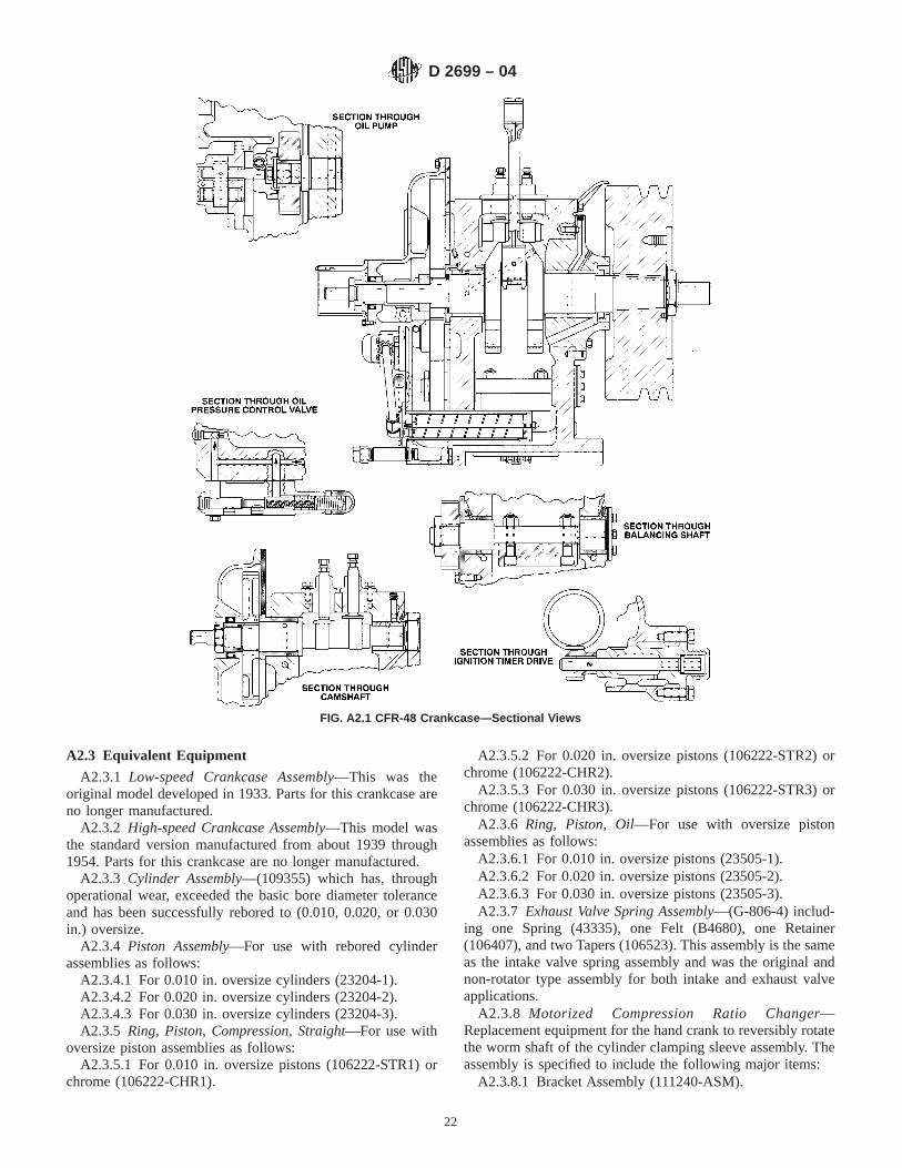
A2.3 Equivalent Equipment
A2.3.1 Low-speed Crankcase Assembly—This was theoriginal model developed in 1933. Parts for this crankcase areno longer manufactured.
A2.3.2 High-speed Crankcase Assembly—This model wasthe standard version manufactured from about 1939 through1954. Parts for this crankcase are no longer manufactured.
A2.3.3 Cylinder Assembly—(109355) which has, throughoperational wear, exceeded the basic bore diameter toleranceand has been successfully rebored to (0.010, 0.020, or 0.030in.) oversize.
A2.3.4 Piston Assembly—For use with rebored cylinderassemblies as follows:
A2.3.4.1 For 0.010 in. oversize cylinders (23204-1).A2.3.4.2 For 0.020 in. oversize cylinders (23204-2).A2.3.4.3 For 0.030 in. oversize cylinders (23204-3).A2.3.5 Ring, Piston, Compression, Straight—For use with
oversize piston assemblies as follows:A2.3.5.1 For 0.010 in. oversize pistons (106222-STR1) or
chrome (106222-CHR1).
A2.3.5.2 For 0.020 in. oversize pistons (106222-STR2) orchrome (106222-CHR2).
A2.3.5.3 For 0.030 in. oversize pistons (106222-STR3) orchrome (106222-CHR3).
A2.3.6 Ring, Piston, Oil—For use with oversize pistonassemblies as follows:
A2.3.6.1 For 0.010 in. oversize pistons (23505-1).A2.3.6.2 For 0.020 in. oversize pistons (23505-2).A2.3.6.3 For 0.030 in. oversize pistons (23505-3).A2.3.7 Exhaust Valve Spring Assembly—(G-806-4) includ-
ing one Spring (43335), one Felt (B4680), one Retainer(106407), and two Tapers (106523). This assembly is the sameas the intake valve spring assembly and was the original andnon-rotator type assembly for both intake and exhaust valveapplications.
A2.3.8 Motorized Compression Ratio Changer—Replacement equipment for the hand crank to reversibly rotatethe worm shaft of the cylinder clamping sleeve assembly. Theassembly is specified to include the following major items:
A2.3.8.1 Bracket Assembly (111240-ASM).
FIG. A2.1 CFR-48 Crankcase—Sectional Views
D 2699 – 04
22

A2.3.8.2 Compression Ratio Changer Motor Assembly(111242). Cranking rotation for these motor and gear driveassemblies is 48 rpm.
A2.3.8.3 Motor Shaft Coupler Assembly (110625-ASM).A2.3.9 Intake Air Refrigeration System Assembly,23
Replacement equipment for the ice tower for dehumidifica-tion of air for engine combustion. This equipment shall deliverconditioned air to the 6 in. Humidifier Tube (109495) of thecritical inlet air system assembly. (Warning—Mechanicalrefrigeration equipment may not be capable of adding watervapor to the conditioned air. If the air in the room where theengine is installed contains less than 25 grains of water per lb(0.00356 kg water per kg) of dry air, ratings can have a bias ofapproximately, 0.05 O.N.)
A2.3.10 Humidity Control System24—Replacement equip-ment for the complete inlet air system assembly for theconditioning of air for engine combustion. This system in-cludes an air compressor, which shall deliver 12 SCFM ofclean, undried air at 60 to 100 psig (0.40 to 0.70 MPa) througha pressure regulator to a bubble tower so that conditioned air atatmospheric pressure is metered for release in an air hoodpositioned above the inlet air pipe to the engine carburetor. Theconditioned air supply slightly exceeds that drawn into theengine inlet pipe for combustion and the excess simply spillsfrom the air hood. The system is specified to include thefollowing major assembly available from Waukesha EngineDivision:
A2.3.10.1 Air Silencer Assembly (110470) with the inlet airheater (106583).
A2.3.11 Inlet Air System Components:A2.3.11.1 Air Surge Pipe Assembly (106616)—Original
equipment, no longer manufactured, may be used instead of theAir Heater Plenum (110412).
A2.3.11.2 Carburetor Air Inlet Pipe, Straight (106684)—Replacement equipment for the Carburetor Inlet Elbow assem-bly (106595).
A2.3.12 Breaker Type Ignition System—Units equippedwith ignition power supply, breaker point distributor, and theignition coil for this early type system are applicable. Parts forthis type system are no longer available.
A2.4 Non-Critical Equipment and Specifications
A2.4.1 A number of components and devices are required tointegrate the critical or equivalent equipment items into acomplete working system or unit. Many of these are commonhardware, tubing, fasteners, and electrical items, potentiallyavailable from multiple sources. In some cases, however,selection of specific sizes or specification criteria are importantto achieve the proper conditions for the knock testing equip-ment unit. Important criteria or specifications are includedwhen applicable. In addition, if an item is available fromWaukesha Engine Division as part of their standard supply, thereference number is given in parenthesis.
A2.4.2 Foundation and Bedplate:A2.4.2.1 Foundation—Typically, in the form of a reinforced
concrete block, site poured, the foundation should be approxi-mately 700-mm wide, 1320-mm long, and a minimum of380-mm high (28-in. wide, 53-in. long, and a minimum of
23 Available from Core Laboratories Refinery Systems, 19 Roszel Rd., Princeton,NJ 08452.
24 Available from GEP Co., 2401 Marilyn Drive, Wilmington, DE 19803.
FIG. A2.2 Cylinder and Clamping Sleeve Assembly
D 2699 – 04
23
13-in. high). If the unit is placed on an industrial building floorof reinforced concrete approximately 200-mm (8-in.) thick, nospecial support for the foundation is required.
A2.4.2.2 Bedplate—(27671) of cast iron, 24-in. wide, 48-in.long, and 4-in. high such that the engine and power absorptionmotor can be solidly mounted and aligned. In addition, thisplatform can be utilized for assembly of accessory electricalequipment, controls, instrumentation and utility connections.
A2.4.3 Heater for Crankcase—(B3109) dual element, 1000W maximum, surface mounting, flat, circular electrical heater.
A2.4.4 Exhaust Discharge System Assembly—Piping, withor without water cooling, suitable to discharge exhaust fumesfrom the combustion chamber to atmosphere, having a flexibleconnection to allow for engine cylinder up and down move-ment, and incorporating adequate volume and length to complywith the specified operating conditions for exhaust backpressure without resonance.
A2.4.4.1 Surge Tank With Water Injection Spray Assembly(109887) assembled with an exhaust manifold assembly(23242) is applicable and requires discharge and support pipingas well as a water drain.
A2.4.4.2 Use of an exhaust manifold of rigid pipe connectedto an exhaust stack by flexible hose and equipped with a waterspray nozzle assembly to inject cooling water prior to theflexible hose is applicable. Packaged systems of this type areavailable from several engineering and support organizations.
A2.4.5 Filter Assembly for Crankcase Oil—(111345-ASM).
A2.4.6 Sample Fuel and Reference Fuel DeliveryComponents—Introduction of fuel to the carburetor vertical jetand a means to switch from one fuel to another may beaccomplished in numerous ways as long as the flow of fuelthrough the carburetor permits the determination of the fuel-airratio for maximum K.I. as dictated by any one of the testprocedures. Typical assemblies are as follows:
A2.4.6.1 Carburetor Selector—Valve assembly, 3 bowl(75961) or 4 bowl (105333) designed to fasten to the carburetorvertical jet flange for delivery of liquid fuel into the jet througha rotary selector-valve supplied by either three or four sourcesof fuel. The selector-valve assembly incorporates stanchionsthat project outward like spokes. Each stanchion houses aninterchangeable horizontal jet, supports a vertically mountedsight glass tube to indicate the level of the particular fuel,includes an inlet opening at the base of the sight glass forconnection to the source container for that particular fuel, andhas a drain connection for fast disposal of unwanted fuel fromboth the source container and the selector-valve passages.
A2.4.6.2 Fuel Tank—Float Reservoir Assembly, three orfour required (75964-ASM), applicable when using testingprocedures that depend on establishing and maintaining thefuel level for the maximum K.I. condition. Each assemblyincludes a fuel tank sight glass assembly and a check valve atthe bottom of the tank operated by a float to establish a constantfuel level in the float reservoir. These assemblies are supportedon carburetor posts integral with a bracket (bar) that is fastenedto the carburetor body. A two-lead screw and nut assembly withadjusting knob is installed in the post and the fuel tank, float
reservoir assembly fastens to the nut so that as the screw isrotated by the knob, the assembly is raised or lowered.
(1) Fuel Tank, without cooling jacket (75962-NC), is appli-cable for reference fuels and also for sample fuels that do notrequire chilling. Fuel tank, with cooling jacket (75962-WC), isapplicable for sample fuels only.
(2) Float Reservoir (chamber), without cooling jacket(75964-NC), is applicable for reference fuels and also forsample fuels that do not require chilling. Float reservoir(chamber), with cooling jacket (75964-WC), is applicable forsample fuels only.
A2.4.6.3 Falling Level Reservoir Assembly, apparatus forsystems that depend on controlled change in fuel level to varyfuel-air ratio at a constant rate from a rich to lean mixture.
NOTE A2.4—Falling level reservoir assemblies are utilized for thebracketing–dynamic fuel level test procedure of this test method and bysome on-line octane analyzer systems for application of Test MethodD 2885.
(1) The cross sectional area of the reservoir determines therate at which the fuel level falls. Within the range thatestablishes a fuel level for maximum K.I. in the carburetorvertical jet between 0.7 and 1.7 in., referenced to the centerlineof the carburetor venturi, the cross sectional area of thereservoir shall be constant and not less than 3830 mm2(5.9in.2).
A2.4.6.4 Spill Carburetor Reservoir Assembly, applicablefor systems that depend on delivering a continuous flow ofsample fuel so that fuel in the vertical jet of the carburetor ismaintained at a constant level located within the range from 0.7to 1.7 in., referenced to the centerline of the carburetor venturi.This type of apparatus requires use of an adjustable delivery(horizontal) jet to vary fuel-air ratio and establish the propersetting for maximum K.I.
NOTE A2.5—A spill carburetor assembly is utilized by some on-lineoctane analyzer systems for application of Test Method D 2885.
A2.4.7 Fuel Flow Control Jet—An orifice having an inter-nal diameter sized to restrict fuel flow to the vertical jet of thecarburetor for use with fuel delivery systems that are dependenton establishing a fuel level in the vertical jet that is within aspecified dimension referenced to the centerline of the carbu-retor venturi.
A2.4.7.1 Horizontal Jet—Specify hole size for method andoperating conditions (75988).
A2.4.7.2 Carburetor Adjustable Horizontal Jet Assembly—Alternative equipment for a hole sized jet (75988). Install atapered needle, screw adjustable, with or without a graduatedscale, so that the needle enters a standard horizontal jet (75988)that is drilled to approximately a 0.050-in. diameter. Adjust-ment of the needle permits changing the flow characteristics offuel delivered to the vertical jet of the carburetor. A change inneedle setting effectively changes the fuel level at which thefuel-air ratio for maximum knock intensity occurs for a specificfuel.
A2.4.8 Belting, Engine Flywheel to Power AbsorptionMotor—Set of two,C section V-belts approximately 2160 mm(85 in.) in length (B5500). The same specification applies forboth 50 and 60 Hz power installations. (Warning—The
D 2699 – 04
24

cross-sectional dimensions of the V-belts are critical for theknock testing unit to operate at the specified rotational speed.)
A2.4.9 Electrical Switchgear—Includes input connectionsand circuit protection for three phase power to operate thepower absorption motor and single phase power to operate
start-stop circuitry, controls, heaters, safety devices, and instru-mentation. Circuit design shall ensure that failure of either thesingle phase or three phase power source will disconnect theother source.
A3. INSTRUMENTATION DESCRIPTION AND SPECIFICATIONS
A3.1 Instrumentation
A3.1.1 The single cylinder test engine unit for the determi-nation of O.N. is manufactured by Waukesha Engine Division,Dresser Industries, Inc., and includes both critical and non-critical instrumentation. Waukesha Engine Division ReferenceNumbers are included in parentheses after all critical items,and where appropriate for non-critical items, although theselatter listings do not imply they are mandatory.
NOTE A3.1—The Waukesha Engine Division Reference Numbers arefor the purpose of specifying components as applicable to this test method.These numbers are not to be used for purchasing parts from the supplier.Users must always refer to the part numbers listed in the current WaukeshaEngine Division CFR Parts Catalog when ordering components.
A3.2 Critical Instrumentation
A3.2.1 Critical instrumentation components or specifica-tions, or both, which shall be used for these test methods, arelisted.
A3.2.2 Knock Measurement System—Determination of theO.N. of spark-ignition engine fuels requires measurement ofthe intensity of knock that is produced in the test enginecombustion chamber. The multicomponent knock measure-ment system instrumentation (see Fig. A3.1) includes a deto-nation pickup (sensor), a detonation meter to condition theknock signal, and a knockmeter to display the K.I. signal. Allof these components are critical because of their empiricaldesign criteria established to make them simulate the knock
measuring characteristics of the bouncing pin system, whichwas the original instrumentation.
A3.2.3 Detonation Pickup—Model D1 (109927) having apressure sensitive diaphragm, magnetostrictive core rod, andcoil incorporated in a hollow steel housing to generate avoltage proportional to rate-of-change of pressure within thecombustion chamber. The specifications are as follows:
A3.2.3.1 Single pin output electrical connector having an11⁄16 – 24 male thread.
A3.2.3.2 7⁄8 – 18 male threaded housing for installation inthe cylinder.
A3.2.3.3 Overall length of 213⁄16 in.A3.2.3.4 Maximum housing diameter of 11⁄16 in.A3.2.3.5 Electrical Resistance Cold, approximately 480V
when measured between the center connector pin and thehousing at room temperature.
A3.2.3.6 Electrical Resistance Hot, approximately 650Vwhen measured between the center connector pin and thehousing at engine operating temperature.
A3.2.3.7 Output Voltage—New pickups are quality controltested to produce at least a 1.8 V positive pulse from zero topeak of the detonation signal spike. This measurement is madewith the pickup operating in a Motor method engine on avolumetric blend of 74 % toluene, 15 %isooctane, and 11 %n-heptane at standard conditions with the pickup center con-nector pin only connected to a calibrated cathode ray oscillo-scope.
FIG. A3.1 Components of Knock Measurement Instrumentation
D 2699 – 04
25

NOTE A3.2—Pickup output voltage normally increases with age asexposure to detonation pressures causes the thin diaphragm to conformmore closely to the curved anvil of the internal core rod assembly. Suchvoltage changes are not known to adversely affect knock intensitymeasurements or octane ratings.
A3.2.4 Detonation Meter—(Model 501-C) The specifica-tions are as follows:
A3.2.4.1 Input filter (low pass) that, for each combustioncycle, develops a characteristic pulse that depicts the rate-of-change of pressure as normal combustion takes place alongwith the sharp pulse resulting from knock. Selection of thecritical frequency range provides the means by which theelectronic metering system duplicates the measurement processbased on the original bouncing pin performance that createdthe O.N. scale. The required signal frequency response char-acteristic is as follows:
Input Frequency, Hz Output Frequency Response, dBdc to 2000 −0.5 6 1.02250 −3.0 6 0.22500 −6.5 6 0.35000 <−406500 6 100 Point where dB drop maximizes and re-
verses (point of minimum output)
A3.2.4.2 Amplifier and associated regulated power supplycircuitry to condition the filtered frequency signal and developa steady output that is proportional to the average portion of therate-of-change of pressure characteristic that is due to knock.This requires subtracting the part of the signal that results fromnormal combustion, integrating the resulting knock pulses andconverting the half-wave ac characteristic to a dc outputpotential for display. Inherent in the measurement process isthe requirement for adjustment of several variables; signal bias(zero) calibration, selection of the degree of integration foracceptable signal-to-noise ratio (time constant), selection of thesensitivity to changes in knock level (spread), and adjustmentof the signal amplification (meter reading) so that the signalcan be scaled for display.
A3.2.4.3 Qualification—Whenever a detonation meter com-ponent is replaced or the meter is suspected of malfunction, testthe detonation meter in accordance with the Model 501-CDetonation Meter Performance Qualification Procedure25 thatspecifies two checks of the electrical functions.
(1) The input filter frequency response characteristic.(2) The peak detection efficiency check which tests the
circuitry to ensure that the knock signals are faithfully trans-mitted throughout the signal conditioning steps to produce theproper output signal.
A3.2.5 Signal Cables:
Cable Description Reference No.Input Cable Detonation pickup to amplifier 210109Output Cable Amplifier to display instrument 111279
A3.2.6 Knockmeter—(109980) having the following speci-fications:
A3.2.6.1 Type—Electrical analogue indicating instrumentoperating on the d’Arsonval principle.
A3.2.6.2 Suspension—Pivot and jewel or taut-band.A3.2.6.3 Scale—Length equal to or greater than 5.0 in. with
angular needle deflection of 250°.A3.2.6.4 Scale Divisions—100 equal valued divisions, ten
major, two intermediate, and five minor.A3.2.6.5 Operating Position—Vertical 620°.A3.2.6.6 Readability—0.5 division by a person of normal
vision viewing from a distance of 1 m (3 ft).A3.2.6.7 Case—Sealed to prevent entrance of dust and
vapors.A3.2.6.8 Range—Incorporate the proper shunt resistance
for the knockmeter by selection and measurement of currentrange and meter resistance as follows:
(1) Knockmeter current, 1.0mA # IM # 3.0 mA.(2) Knockmeter resistance, RM # (0.0325/IM) − 9.901V.(3) Measurement of Knockmeter Resistance—
Simultaneously measure the full scale current through theknockmeter,IM, and the voltage drop across the knockmeter,VM. ComputeRM = VM/IM.
(4) Compute the correct shunt resistance to be used withthe knockmeter:
RS 51000RMIM
3.282 IM ~10001 RM!(A3.1)
(5) Connect this value ofRS securely and permanentlyacross the knockmeter terminals.
NOTE A3.3—A knockmeter with a selected shunt resistance connecteddirectly across it can only be utilized with a detonation meter (model 501types) amplifier circuit that includes an output resistance, R-260 of 1000V but does not include an internal shunt resistor, R-261 = 10V.
A3.2.6.9 Precision and Damping Check—The knockmeterwith applied shunt resistance shall comply with the require-ments of the following test procedure:
(1) Adjust the knockmeter pointer to zero.(2) Connect the knockmeter (shunted) to a variable voltage
source in series with a resistor of 1000V 6 1 %.(3) Range Check—Apply an exciting voltage (Ve) to
produce a full scale knockmeter reading of exactly 100 (withtapping). Record the voltage across the knockmeter asVfs.
Required:Vfs 5 3.28V 6 5 % (A3.2)
(4) Knockmeter Tracking Error (TE) Check—Apply anexciting voltage (Ve) to sequentially produce knockmeterreadings (M) of 20, 30, 40, 50, 60, 70, and 80 divisions on theknockmeter scale. RecordM andVe, at each point.
ComputeTE5 M 2 ~Ve/Vfs! 3 100 for each point (A3.3)
Required: MaximumTE 5 61 %
(5) Repeatability Check—Without tapping or overshoot,apply an exciting voltage to exactly produce a mid-scale (50)knockmeter reading. Record the voltage across the knockmeterasVA. Increase the exciting voltage until full-scale deflection ora knockmeter reading of 100 is obtained, then reduce theexciting voltage until, without overshoot or tapping, theknockmeter is again at mid-scale (50). Record the voltageacross the knockmeter asVB.
Compute repeatability5 [~VA 2 VB!/Vfs# 3 100 (A3.4)
Required: Maximum repeatability5 60.5 %
25 Supporting data have been filed at ASTM International Headquarters and maybe obtained by requesting Research Report RR: D02-1326.
D 2699 – 04
26

(6) Damping Check—By trial and error, determine thatvalue of exciting voltage that, when suddenly applied, willcause the knockmeter to swing to exactly full scale (M = 100).When the needle comes to rest, recordMr.
Compute percent overshoot5 [~1002 Mr!/Mr# 3 100 (A3.5)
Required: Overshoot of less than 25 %
A3.2.6.10 The knockmeter shall meet or exceed any otherperformance requirements of USA Standard C-39.1 (AmericanNational Standards Institute C39.1—1992) for millimetres ofaccuracy class 1.0.
A3.2.7 System Tracking Accuracy Check—The knockmeterconnected to the detonation meter shall respond accurately andlinearly to specific input signals based on measurementsdetermined using the following procedure:
A3.2.7.1 Test Equipment Required:(1) Stable dc signal source, such as Size D alkaline battery
(1.5 V).(2) Battery holder.(3) Amphenol No. 80, MC2M cable plug for connecting
the signal source to the detonation meter input connector.(4) Detonation meter.(5) Single conductor, insulated, electrical wire.(6) Knockmeter.(7) Assemble test equipment components in accordance
with Fig. A3.2.A3.2.7.2 Check Procedure—Perform the following steps
with the engine stopped to minimize electrical interference:(1) Turn off the detonation meter POWER switch and
record METER READING and SPREAD control dial settingsto facilitate return to normal operating conditions at thecompletion of this check procedure.
(2) Zero the knockmeter needle mechanically, using theadjusting screw provided on the knockmeter face.
(3) Disconnect the pickup cable from the detonation meterinput socket and connect the dc signal source to this socket.
(4) Turn on the detonation meter POWER switch.(5) Set the detonation meter METER switch to OPERATE,
the coarse SPREAD (outer step dial) control to 5, the fineSPREAD (inner dial) fully counterclockwise to 0 and theTIME CONSTANT selector to 1.
(6) Adjust METER READING coarse and fine controls toachieve a mid-scale knockmeter reading and allow the systemto reach equilibrium.
(7) Establish a knockmeter reading of 80 by first setting theSPREAD coarse control to 8 and then adjusting the METERREADING dial to obtain exactly 80 knockmeter divisions.(Warning—Allow 10 s for equilibrium after any change andtap the knockmeter near its pivot point before each reading inthis and succeeding steps.)
(8) Establish a knockmeter reading of 20 by first setting theSPREAD coarse control to 2 and then adjusting the ZEROscrew to obtain exactly 20 knockmeter divisions.
NOTE A3.4—The ZERO screw is accessible by removing the restrainedcap cover.
(9) Repeat the last two interacting steps to establish pre-cisely 80 and 20 knockmeter readings when the SPREADcoarse control is set to 8 and 2 respectively.
(10) Record the knockmeter reading for each SPREADcoarse control setting from 2 through 8.
NOTE A3.5—A perfectly linear knockmeter system should produceknockmeter readings that are exactly ten times the SPREAD coarse
FIG. A3.2 Test Signal Source—Knockmeter Tracking Accuracy Check
D 2699 – 04
27
control setting.Example—A SPREAD coarse control setting of 5 shouldresult in a knockmeter reading of 50.
(11) If the knockmeter reading for any SPREAD coarsecontrol setting deviates by more than two divisions fromlinearity, the tracking accuracy is inadequate and appropriaterepairs are required.
NOTE A3.6—Non-linearity is typically caused by a defective knockme-ter.
(12) When the tracking accuracy check is completed, re-store the instrument connections and reset the detonation meterSPREAD and METER READING dials for normal operation.
A3.2.8 Temperature Measurement:A3.2.8.1 Intake Air Thermometer Assembly(106317-
ASM), using a thermometer having a range from 15 to 70°Cgraduated in 1°C divisions (60 to 160°F graduated in 1°Fdivisions) and conforming to the requirements for Thermom-eter 83C (83F) in Specification E 1.
NOTE A3.7—The thermometer or other components of the intake airthermometer assembly are not available as separate items.
A3.2.9 Pressure Measurement:A3.2.9.1 Compression Pressure Gage Assembly(110304-
ASM), including a 0 to 300 psiPressure Gage (105028),Deflator Assembly (110305), Flexible Hose Assembly(110641), Barrel (75777), Check Valve Assembly (105033),Screen Plug Assembly (75988-ASM), and Check Valve Washer(75941). The complete assembly shall be regularly calibratedusing suitable pneumatic dead weight testing equipment.
A3.2.10 Cylinder Height Measurement:A3.2.10.1 Compression Ratio (Digital) Counter Assembly(110514-ASM), including compression Ratio Counter
(110514), Flexible Shaft (110513) and associated hardware forconnection of the flexible shaft to the engine cylinder clampingsleeve and worm shaft.
(1) The digital counter assembly is required for knocktesting units that are used for octane ratings determined usingthe C.R. procedure. It may also be utilized for knock testingunits used for octane ratings determined by the bracketingprocedures.
(2) One digital counter unit is equivalent to one tenthrevolution of the worm shaft and represents 0.0007 in. ofcylinder height movement.
A3.2.10.2 Dial Indicator Assembly(110279-ASM), includ-ing Dial Indicator (110279), Indicator Bracket (110631), Ad-justing Screw (111243), Adjusting Screw Bracket (110349) andassociated hardware for connection of the dial indicator andbracket to the engine clamping sleeve and the adjusting screwand bracket to the engine cylinder assembly.
(1) The dial indicator assembly is only applicable for knocktesting units that are used for octane rating determined by thebracketing procedures.
(2) The dial indicator assembly provides a direct measureof cylinder height movement and is readable to 0.001 in.Although it is not required when a compression ratio digitalcounter assembly is utilized, it may be used, on units soequipped, as a secondary or backup reference of cylinderheight.
A3.3 Equivalent Instrumentation
A3.3.1 Detonation Meter—Model 501-T—This instrumentis no longer manufactured.
A3.3.1.1 Input filter (low pass), having the same signalfrequency response characteristic specified for the Model501-C detonation meter.
A3.3.1.2 Amplifier and associated regulated power supplycircuitry to condition the filtered frequency signal and developa steady output that is proportional to the average portion of therate-of-change of pressure characteristic that is due to knock.
NOTE A3.8—The Model 501-T detonation meter can be checked usingthe procedures that are given in ASTM Research Report D02-1326.25
However, application of these procedures may not be very useful.
A3.3.2 Strip-chart Recorder, for K.I. indication, can beconnected to the detonation meter output in parallel with theknockmeter. Select a recorder meeting the following specifi-cation:
A3.3.2.1 Input Signal Range—10.0 mV full-scale.A3.3.2.2 Input Impedance—Greater than 1 meg ohm.A3.3.2.3 Scale—Length equal to or greater than 127 mm
(5.0 in.).A3.3.2.4 Scale Divisions—100 equal valued divisions, ten
major, two intermediate, and five minor.A3.3.2.5 Chart Speed—127 to 254 mm/h (5 to 10 in./h) is
adequate. The user may specify another chart speed range ifdesired.
A3.3.2.6 The recorder shall have an ungrounded differentialinput for parallel operation with a knockmeter, both terminalsof which are approximately 50 V dc above ground.
A3.3.2.7 Recorder zero and span adjustment features aredesirable. A recorder and knockmeter connected in parallelmay not read the same value of K.I. Recorder zero and spanadjustment is permissible to cause the instruments to agreeover the range from 20 to 80 divisions. If these adjustmentfeatures are not available on a specific instrument, connect a1000 ohm, 1 W precision multi-turn potentiometer across therecorder input signal terminals and adjust it to cause theinstruments to read the same.
A3.4 Non-Critical Instrumentation
A3.4.1 Temperature Measurement:A3.4.1.1 Temperature Controller(111412), with associated
thermal sensor, for on/off or proportional temperature controlto within the specified limits as measured by the Intake AirThermometer.
A3.4.1.2 Cylinder Jacket Coolant ThermometerAssembly(105180-ASM), using a thermometer having a rangefrom −15 to 105°C graduated in 1°C divisions (0 to 220°Fgraduated in 2°F divisions) and conforming to the require-ments for Thermometer 82C (82F) in Specification E 1.
NOTE A3.9—The thermometer or other components of the cylinderjacket coolant thermometer assembly are not available as separate items.
A3.4.1.3 Engine Crankcase Lubricating Oil TemperatureIndicator (105321), having a range from 15 to 85°C readableto 3°C (60 to 180°F readable to 5°F).
A3.4.2 Pressure Measurement:
D 2699 – 04
28
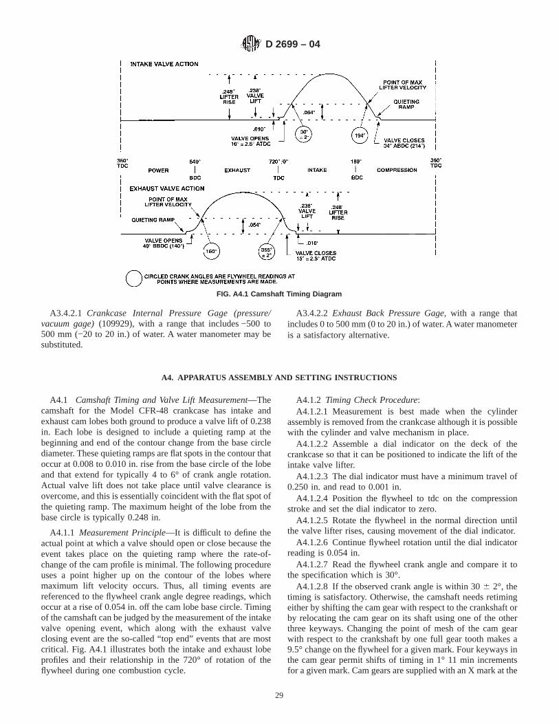
A3.4.2.1 Crankcase Internal Pressure Gage (pressure/vacuum gage)(109929), with a range that includes −500 to500 mm (−20 to 20 in.) of water. A water manometer may besubstituted.
A3.4.2.2 Exhaust Back Pressure Gage, with a range thatincludes 0 to 500 mm (0 to 20 in.) of water. A water manometeris a satisfactory alternative.
A4. APPARATUS ASSEMBLY AND SETTING INSTRUCTIONS
A4.1 Camshaft Timing and Valve Lift Measurement—Thecamshaft for the Model CFR-48 crankcase has intake andexhaust cam lobes both ground to produce a valve lift of 0.238in. Each lobe is designed to include a quieting ramp at thebeginning and end of the contour change from the base circlediameter. These quieting ramps are flat spots in the contour thatoccur at 0.008 to 0.010 in. rise from the base circle of the lobeand that extend for typically 4 to 6° of crank angle rotation.Actual valve lift does not take place until valve clearance isovercome, and this is essentially coincident with the flat spot ofthe quieting ramp. The maximum height of the lobe from thebase circle is typically 0.248 in.
A4.1.1 Measurement Principle—It is difficult to define theactual point at which a valve should open or close because theevent takes place on the quieting ramp where the rate-of-change of the cam profile is minimal. The following procedureuses a point higher up on the contour of the lobes wheremaximum lift velocity occurs. Thus, all timing events arereferenced to the flywheel crank angle degree readings, whichoccur at a rise of 0.054 in. off the cam lobe base circle. Timingof the camshaft can be judged by the measurement of the intakevalve opening event, which along with the exhaust valveclosing event are the so-called “top end” events that are mostcritical. Fig. A4.1 illustrates both the intake and exhaust lobeprofiles and their relationship in the 720° of rotation of theflywheel during one combustion cycle.
A4.1.2 Timing Check Procedure:A4.1.2.1 Measurement is best made when the cylinder
assembly is removed from the crankcase although it is possiblewith the cylinder and valve mechanism in place.
A4.1.2.2 Assemble a dial indicator on the deck of thecrankcase so that it can be positioned to indicate the lift of theintake valve lifter.
A4.1.2.3 The dial indicator must have a minimum travel of0.250 in. and read to 0.001 in.
A4.1.2.4 Position the flywheel to tdc on the compressionstroke and set the dial indicator to zero.
A4.1.2.5 Rotate the flywheel in the normal direction untilthe valve lifter rises, causing movement of the dial indicator.
A4.1.2.6 Continue flywheel rotation until the dial indicatorreading is 0.054 in.
A4.1.2.7 Read the flywheel crank angle and compare it tothe specification which is 30°.
A4.1.2.8 If the observed crank angle is within 306 2°, thetiming is satisfactory. Otherwise, the camshaft needs retimingeither by shifting the cam gear with respect to the crankshaft orby relocating the cam gear on its shaft using one of the otherthree keyways. Changing the point of mesh of the cam gearwith respect to the crankshaft by one full gear tooth makes a9.5° change on the flywheel for a given mark. Four keyways inthe cam gear permit shifts of timing in 1° 11 min incrementsfor a given mark. Cam gears are supplied with an X mark at the
FIG. A4.1 Camshaft Timing Diagram
D 2699 – 04
29

tooth to be aligned with the corresponding X mark on thecrankshaft gear. If another keyway is used, the gear X mark isirrelevant and the proper tooth for the unmarked keyway mustbe determined. Greater detail is available from the manufac-turer.
NOTE A4.1—The other valve opening and closing events may also bechecked but the single measurement based on the intake valve openingevent is sufficient to make the judgment as to proper camshaft timing.
A4.1.3 Valve Lift Check Procedure:A4.1.3.1 With the dial indicator still positioned over the
intake valve lifter, continue rotation of the flywheel until amaximum reading is obtained on the dial indicator.
A4.1.3.2 Read the dial indicator and compare it to thespecification, which is 0.246 to 0.250 in. If the rise is less than0.243 in. from the base circle of the cam, wear of the lobeoccurred and camshaft replacement is indicated.
A4.1.3.3 Valve lift for the exhaust cam lobe should also bechecked by repeating the procedure with the dial indicatorpositioned over that valve lifter. The lift specification is thesame as for the intake valve lifter.
A4.2 Basic Cylinder Height Indexing:
A4.2.1 Measurement Principles—Compression ratio is asignificant variable in relation to knock in internal combustionengines and is a basic parameter for the knock testing methods.The CFR engine cylinder and clamping sleeve mechanismprovide a means to change C.R. by moving the cylinder up ordown with respect to the crankcase. As a convenient alternativeto determination of the actual C.R., the vertical position of thecylinder can be measured and provides an indication that isproportional to C.R. Two approaches to indicating the cylinderheight are applicable as follows:
A4.2.1.1 Compression Ratio Digital Counter Assembly—See Fig. A4.2. A flexible cable connects the cylinder clampingsleeve worm shaft to a mechanical digital counter unit that hastwo digital display counters or indicators. The input shaft of theunit is directly connected to the upper digital indicator and thedigital counter reading responds to any rotation of the wormshaft which moves the engine cylinder up or down. The lowerdigital indicator is directly connected to the input shaft of theunit when a selector knob is positioned to 1 but is disengaged
when the selector knob is at any other position. The disengage-ment feature is utilized to offset the lower indicator from theupper indicator so that the differential digital counter readingcan be compensated for other than standard barometric pres-sure conditions. The reading on the lower digital counter thusprovides compensated values for knock test units operated atother than standard 29.92 in. Hg (101.0 kPa) barometricpressure conditions. Digital counter reading changes in directproportion to C.R. and a digital counter reading change of onedigit is equal to 0.0007 in. movement of the cylinder height.
A4.2.1.2 Dial Indicator Assembly—See Fig. A4.3. The dialindicator is fastened to the cylinder clamping sleeve by abracket. An adjusting screw with a flat circular anvil thatcontacts the spindle of the dial indicator is supported in asecond bracket, which is fastened to the engine cylinder. Theadjusting screw provides the means to set the dial indicator tothe proper reading when the device is being indexed and is thenlocked in place by a lock nut tightened against the bracket. Dialindicator readings change in inverse proportion with respect toC.R., increasing in value when the cylinder is raised in theclamping sleeve. Cylinder height movement is indicated to thenearest 0.001 in. There is currently no commercial offsetmechanism to provide directly compensated dial indicatorreadings for knock test units operated at other than standard29.92 in. Hg (101.0 kPa) barometric pressure conditions.
FIG. A4.2 C.R. Digital Counter
FIG. A4.3 Cylinder Height Dial Indicator
D 2699 – 04
30

A4.2.2 Establishing Basic Cylinder Height—The cylinderheight measurement instruments must be indexed to a stan-dardized value after every top overhaul or equipment changethat affects the combustion chamber. Originally, the clearancevolume of the combustion chamber was set by introducing aspecified volume of water to fill the clearance volume to the topof the pickup hole and then setting the indicator to a specificvalue. Experience has demonstrated that cylinder height index-ing can be achieved by adjusting the cylinder position until aspecified compression pressure is produced dependent on theprevailing barometric pressure. Fig. 2 is utilized to indicate thecompression pressure that must be produced at standardoperating conditions with the CFR engine motoring. Thecylinder height instrument is then set to the uncompensatedbasic value. For C.R. digital counter assemblies, the basicdigital counter reading is 930. For dial indicator assemblies, thebasic dial indicator reading is 0.352 in.
A4.2.3 Basic Cylinder Height Indexing Procedure:A4.2.3.1 Operate the knock test unit for sufficient time to
reach temperature equilibrium, on a typical sample fuel, atstandard operating conditions with the IAT regulated to thevalue specified in Annex A6 tables for the prevailing baromet-ric pressure. (Warning—In addition to other precautions, usersof the C.R. digital counter assembly are urged to set the upperand lower digital counters so that they both display the samevalue to ensure that indexing will be based on an uncompen-sated reading.)
A4.2.3.2 Cylinder height indexing requires the determina-tion of compression pressure using the compression pressuregage assembly specified as critical instrumentation. The gageassembly shall have been calibrated in accordance with theinstructions provided by the manufacturer. See Fig. A4.4.
A4.2.3.3 The following steps shall be performed as quicklyas possible to ensure that the pressure readings represent hotengine conditions.
(1) Collect and have ready, a calibrated compression pres-sure gage assembly and the tools required to remove thedetonation pickup and install the gage assembly in the com-bustion chamber pickup hole.
(2) Users of the C.R. digital counter assembly shall discon-nect the flexible cable by loosening the set-screw and slippingthe cable connector off the digital counter unit and manually setthe upper and lower digital counter readings so that both read930.
(3) Determine the prevailing barometric pressure and usingFig. 2, read the compression pressure expected for cylinderheight instrument indexing.
(4) Shut the engine down by turning the fuel off, turning theignition switch off, and then positioning the engine powerswitch to off.
(5) Drain all fuel from the carburetor.(6) Remove the detonation pickup cable connector, unscrew
the detonation pickup from the cylinder, and install thecompression pressure gage assembly. (Warning—Avoid con-tact with the detonation pickup because it is extremely hot andcan cause serious burns.)
(7) Check that the ignition switch is off and that all fuel hasbeen drained from the carburetor.
(8) Restart the engine and operate in a motoring mode only.(9) Observe the compression pressure gage reading and
adjust the cylinder height so that the expected compressionpressure is indicated. Release the pressure once or twice usingthe deflator valve and make any required change in cylinderheight so that the expected compression pressure is obtained.(Warning—In addition to other precautions, read the compres-sion pressure gage in whatever position it faces withouttwisting the gage and hose, which can distort the readings.)
(10) Users of the C.R. digital counter assembly must recon-nect the flexible cable to the unit and tighten the set-screwwhile being careful not to change the digital counter readingsfrom 930.
(11) Users of the dial indicator assembly must loosen thelock nut, set the adjusting screw so that the dial indicatorreading is 0.352 in., and then tighten the lock nut. Severalrepeats of the adjustment may be required to obtain the0.352-in. reading when the lock nut is retightened.
(12) Shut the engine down, remove the compression pres-sure gage assembly, install the detonation pickup with a newgasket, and tighten the pickup to the torque setting specified inTable A4.1.
A4.3 Checking Compression Pressures—Checking com-pression pressure with the engine operating at each of twodifferent C.R. conditions can be a useful indicator of combus-tion chamber and valve condition. The C.R. values selected formaking the research method checks are those for 93.4 and 105O.N. levels.
A4.3.1 Operate the knock test unit for sufficient time toreach temperature equilibrium, on a typical sample fuel havingan O.N. between 95 and 100, at standard operating conditionsand with the IAT regulated to 51.76 1°C (1256 2°F).
A4.3.2 Collect and have ready, a calibrated compressionpressure gage assembly and the tools required to remove the
FIG. A4.4 Compression Pressure Gage Assembly
D 2699 – 04
31

detonation pickup and install the gage assembly in the com-bustion chamber pickup hole.
A4.3.3 Shut the engine down by turning the fuel off, turningthe ignition switch off and then positioning the engine powerswitch to off.
A4.3.4 Drain all fuel from the carburetor.A4.3.5 Remove the detonation pickup cable connector,
unscrew the detonation pickup from the cylinder, and installthe compression pressure gage assembly. (Warning—Avoidcontact with the detonation pickup because it is extremely hotand can cause serious burns.)
A4.3.6 Check that the ignition switch is off and that all fuelhas been drained from the carburetor.
A4.3.7 Restart the engine and operate in a motoring modeonly.
A4.3.8 Determine the compression pressures at the cylinderheight settings for the two O.N. levels in accordance with TableA4.2:
A4.3.8.1 Use cylinder height settings compensated for baro-metric pressure as specified in Annex A6 tables.
A4.3.8.2 Observe the compression pressure and record thereadings.
A4.3.8.3 If the compression pressures are not within thelimits, repeat the basic cylinder indexing procedure, and ifnecessary, perform the maintenance required to obtain theproper compression characteristic.
A4.4 Setting Standard K.I.—O.N. ratings, regardless ofoctane level or barometric pressure, are presumed to bedetermined at approximately the same degree of knock, whichis termed standard K.I. Every engine follows a natural track orcharacteristic of cylinder height variation with changes in O.N.that is based on the assumed standard K.I. The average of thevalues determined for numerous engines defines the guide tableof standard K.I. for this test method. The basic setting,established when the detonation meter was first accepted,duplicated the cylinder height at 85 O.N., which had been usedfor the original bouncing pin. “Setting the engine on the guidetable,” a term that has been utilized historically, denotesoperating the engine on a PRF blend of known O.N., understandard conditions, with the cylinder height set to the valuespecified by the appropriate guide table. If the fuel-air ratio isthen adjusted to the maximum knock condition, the engine will
be operating at standard K.I. Adjustment of the detonationmeter to cause the knockmeter to read 506 2 divisions,establishes the required numerical display of this standardizedknock condition.
A4.4.1 The procedure for setting standard K.I. at anyselected O.N. level is as follows:
A4.4.1.1 Prepare a PRF blend for the O.N. selected andintroduce it to a fuel tank and position the fuel selector-valve tooperate the engine on this fuel.
A4.4.1.2 Using the appropriate guide table from Annex A6,and the proper compensation for other than standard baromet-ric pressure (see Annex A6 tables), determine the cylinderheight (digital counter or dial indicator reading) and adjust thecylinder height to this value.
A4.4.1.3 Determine the fuel-air ratio for maximum K.I.A4.4.1.4 Adjust the detonation meter, METER READING,
dials so that the knockmeter reading averages 506 2 divisions.
A4.5 Setting Overall Knock Measurement System Param-eters:
A4.5.1 Principles of Knock Measurement—The knock mea-surement system incorporates the detonation pickup, detona-tion meter, and the indicating knockmeter as illustrated in Fig.A4.5. The rate-of-change of combustion chamber pressuresignal produced by the detonation pickup is modulated by thedetonation meter input filter circuit to create a signal that willsimulate the octane rating characteristics of the original bounc-ing pin instrumentation. Further conditioning of this signal bythe detonation meter circuitry subtracts away the portion thatrepresents normal or knock-free operation, amplifies andstretches the remaining knock pulse, integrates multiple cyclesof the knock pulse to average the engine characteristic, andfinally produces a dc output signal proportional to knock fordisplay on the knockmeter.
A4.5.2 Spread Characteristic—Detonation meter spread orsensitivity (K.I. divisions per O.N.) is a function of thedetonation meter SPREAD dial settings. Regardless of thespread dial setting, however, K.I. divisions per O.N. varies asO.N. level is changed because of the engine operating charac-teristics and the nature of the O.N. scale. The effect of spreadvariation with O.N. level for a selected spread dial setting isillustrated in Fig. A4.6. In the 80 to 100 O.N. range, themaximum amount of spread achievable can be greater thandesired because K.I. reading may become too unstable forsatisfactory observation (excessive signal-to-noise ratio). How-ever, as the figure demonstrates, a workable spread setting canbe selected to permit rating over a wide O.N. range. Use of aspread set to approximately 12 to 15 for the 90 O.N. leveltypically achieves this condition and reduces the frequency ofmaking spread dial changes when testing sample fuels in thecommercial fuel O.N. range. When testing samples at levels
TABLE A4.1 Torque Specification Values
Item Torque, lbf-ft Torque, N-m
Cylinder clamping sleeve:Long stud nuts 42 57Short stud nuts 83 113
Cylinder clamping cam bolt nutA 10 14Cylinder clamping bolt nutB 5 7Crankshaft balancing weight bolts 100 136Balancing shaft weight bolts 100 136Balancing shaft weight bolt locknuts 75 102Balancing rod bolts (high speed crankcase) 100 136Connecting rod bolts 104 141Flywheel nut 200 271Spark plug 25 to 30 34 to 41Detonation pick-up, type D-1 30 41
A With clamp handle in locked position. (Warning— Do not exceed 25 lbf-ft toavoid cylinder distortion.)
B When motorized C.R. changer is used.
TABLE A4.2 Specifications for Checking Compression Pressures
Octane number 93.4 105Compensated digital counter setting 778 1061Compensated dial indicator setting, in. 0.460 0.259Compression pressure, psi 169 6 2 2416 4
(1.16 6 0.01) (1.66 6 0.02)
D 2699 – 04
32

below 80 O.N., spread naturally decreases and spread dialchanges are desirable to maximize sensitivity for optimummeasurement resolution at these lower O.N. levels. Spread canalso naturally decrease as O.N. is increased above 100.Resetting the spread dials becomes necessary, in this case, notonly to gain measurement resolution but more importantly, toensure that the electronic conditioning of the detonation metercircuitry removes the portion of the measured signal thatrepresents normal combustion. At these high O.N. levels, it isimportant that the retained signal represent the knock functionand not a “knockless knock” measurement.
A4.5.3 Setting Spread—Setting spread at any selected O.N.level involves adjustment of the detonation meter SPREADand METER READING controls. Each control has indepen-dent coarse and fine adjustment dials. See Fig. A4.7. Thecontrol ratio of the coarse dial (10 point switch) to the fine dialis 10:1 for both SPREAD and METER READING controls.Change spread as follows:
A4.5.3.1 Operate the engine on the PRF blend for theselected O.N. level at standard operating conditions.
A4.5.3.2 To increase spread, increase the knockmeter read-ing to 80 or more by adjusting the fine spread dial clockwiseand then reduce the knockmeter reading to 506 3 by adjustingthe fine meter reading dial counterclockwise.
A4.5.3.3 To decrease spread, decrease the knockmeter read-ing to 20 or less by adjusting the fine spread dial counterclock-wise and then increase the knockmeter reading to 506 3 byadjusting the fine meter reading dial clockwise.
A4.5.3.4 If at any point during the spread adjustmentprocedure, adequate range of adjustment is not possible using
the fine controls, the coarse dial for that function should bemoved so that proper range is available using the fine dial.
A4.5.4 Measuring Spread—Spread is measured using eithera two PRF technique or a one PRF technique. In every case,adjust the PRF fuel-air ratio to produce maximum knockintensity.
A4.5.4.1 The two PRF technique measures the change inK.I. divisions that occurs when the engine, operating at theguide table C.R. or cylinder height for the O.N. of one PRF, isswitched to the second PRF that is either 1.0 O.N. higher orlower than the first PRF.
A4.5.4.2 The single PRF technique measures the change inK.I. divisions that occurs when the engine is first operated atthe guide table C.R. for the O.N. of the PRF and then at theC.R. equivalent to one O.N., either higher or lower than that ofthe PRF.
A4.6 Adjusting Crankcase Lubricating Oil Pressure—Theoil pressure of the lubricating oil in the engine crankcasegallery is dependent on the setting of the pressure control valvelocated at the lower left side of the engine crankcase whenviewed from in front of the engine. See Fig. A4.8.
A4.6.1 Adjust the oil pressure with the engine hot andrunning.
A4.6.2 Remove the acorn nut and gasket from the oilpressure control valve assembly.
A4.6.3 Loosen the gasketed locknut so that the adjustingscrew is free.
A4.6.4 While observing the engine oil pressure gage, set theadjusting screw to obtain the specified 172 to 207 kPa (25 to 30psi) pressure.
A4.6.5 Tighten the gasketed locknut while observing thatthe pressure remains within limits.
A4.6.6 Reinstall the gasket and acorn nut.
A4.7 Engine Torque Tightening Specifications—See TableA4.2.
FIG. A4.5 Block Diagram of Knock Measurement System
FIG. A4.6 Typical Detonation Meter Spread Characteristic
FIG. A4.7 Detonation Meter—Front Panel
D 2699 – 04
33

A5. REFERENCE FUEL BLENDING TABLES
A5.1 See Tables A5.1-A5.3.
FIG. A4.8 Oil Pressure Control Valve Assembly
TABLE A5.1 Octane Numbers for Blends of 80 Octane PRF andn-Heptane
Blends of 80 PRF and n-HeptaneA
Octane Number Percent 80 PRF Percent n-Heptane
40.0 50 5044.0 55 4548.0 60 4052.0 65 3556.0 70 3060.0 75 2564.0 80 2068.0 85 1572.0 90 1072.8 91 973.6 92 874.4 93 775.2 94 676.0 95 576.8 96 477.6 97 378.4 98 279.2 99 180.0 100 0
A O.N. = 0.80 (% 80 PRF).
D 2699 – 04
34

A6. GUIDE TABLES OF CONSTANT KNOCK INTENSITY
A6.1 See Tables A6.1-A6.5.
TABLE A5.2 Octane Numbers for Blends of 80 Octane PRF and Isooctane
Blends of 80 PRF and IsooctaneA
Octane Number Percent 80 PRF Percent Isooctane
80.0 100 081.0 95 582.0 90 1083.0 85 1584.0 80 2085.0 75 2586.0 70 3087.0 65 3588.0 60 4089.0 55 4590.0 50 5091.0 45 5592.0 40 6093.0 35 6594.0 30 7095.0 25 7596.0 20 8097.0 15 8598.0 10 9099.0 5 95
100.0 0 100A O.N. = 0.80 (% 80 PRF) + 1.00 (% isooctane).
TABLE A5.3 Octane Numbers for Blends of Tetraethyllead inIsooctane A
NOTE—Dilute tetraethyllead (mL TEL/gal basis) is prepared so thatwhen 2.0 mL of dilute fluid are added to a 400-mL batch ofisooctane, theresulting blend will contain 2.0 mL TEL per U.S. gallon.
mL TEL perU.S. gal
Octane NumbermL TEL per
U.S. galOctane Number
0.0 100.0 1.2 109.60.05 100.7 1.4 110.50.1 101.3 1.5 111.00.2 102.5 2.0 112.80.3 103.5 2.5 114.30.4 104.4 3.0 115.50.5 105.3 3.5 116.60.6 106.0 4.0 117.50.7 106.8 4.5 118.30.8 107.4 5.0 119.10.9 108.0 5.5 119.71.0 108.6 6.0 120.3
A O.N.~above 100! 5 100 128.28 ~T!
1.0 1 0.736 ~T! 1 [1.0 1 1.472 ~T! 2 0.035216 ~T!2#0.5
where: T = mL TEL per U.S. gal in isooctane.
D 2699 – 04
35

TABLE A6.1 Guide Table for Standard Knock Intensity at Standard Barometric Pressure A—9⁄16 in. VenturiDigital Counter Readings for Research Octane Numbers
NOTE—See Tables A6.4 and A6.5 for digital counter reading compensation for barometric pressures other than 101.0 kPa (29.92 in. Hg).
ResearchOctaneNumber
0.0 0.1 0.2 0.3 0.4 0.5 0.6 0.7 0.8 0.9
Digital Counter Readings
40 357 357 357 357 358 359 359 359 360 36041 361 361 361 362 362 363 363 363 364 36442 364 365 365 366 366 366 367 367 368 36843 368 369 369 370 370 370 371 371 372 37244 373 373 373 374 374 375 375 375 376 376
45 377 377 378 378 379 379 380 380 381 38246 382 383 383 384 384 385 385 386 386 38747 387 388 388 389 389 389 390 390 390 39048 391 391 392 392 393 393 394 395 395 39649 396 397 397 398 399 399 400 400 401 402
50 402 403 403 404 404 405 405 406 406 40651 407 408 408 409 410 410 411 411 412 41252 412 413 413 414 414 415 415 416 417 41753 418 418 419 419 420 420 421 422 422 42354 423 424 424 425 426 426 427 427 428 428
55 429 429 430 430 431 432 432 433 433 43456 435 435 436 436 437 437 438 439 439 44057 440 441 441 442 442 443 443 444 444 44558 446 446 447 448 448 449 449 450 450 45159 451 452 453 453 454 454 455 455 456 457
60 457 458 458 459 460 460 461 461 462 46261 463 464 465 465 466 467 467 468 469 47062 470 471 471 472 472 473 474 474 475 47563 476 477 478 478 478 479 479 480 481 48164 482 483 484 484 485 485 486 486 487 488
65 488 489 490 491 491 492 492 493 494 49566 495 496 497 498 498 499 500 501 501 50267 502 503 503 504 505 506 507 508 508 50968 509 510 510 511 512 513 513 514 515 51569 516 517 517 518 519 519 520 520 521 522
70 523 524 525 525 526 526 527 527 528 52971 530 531 532 532 533 533 534 534 535 53672 537 538 539 539 540 540 541 542 543 54473 545 546 546 547 548 548 549 550 551 55274 553 554 554 555 556 557 558 559 560 560
75 561 562 563 564 565 566 567 567 568 56976 570 571 572 573 574 575 576 577 578 57977 580 581 581 582 583 584 585 586 587 58878 589 590 591 592 593 594 595 596 597 59879 599 600 601 602 603 604 605 606 607 60880 609 610 611 612 613 614 615 616 617 61881 619 620 621 622 623 624 625 626 627 62882 629 630 631 632 633 634 635 636 637 63983 640 641 642 643 644 645 646 647 648 64984 650 651 652 653 654 656 657 658 659 660
85 661 663 664 666 667 668 669 670 671 67286 673 674 675 677 678 680 681 682 683 68487 685 687 688 689 691 692 694 695 697 69888 699 700 701 702 704 705 706 708 709 71189 712 713 715 716 718 719 721 722 723 725
90 726 728 729 730 732 733 735 736 737 73991 740 742 743 744 746 747 749 750 752 75392 756 757 759 760 761 763 764 766 767 76893 770 772 774 776 778 780 781 783 784 78594 787 789 791 793 795 797 799 801 802 804
95 805 807 809 811 812 814 816 818 820 82296 824 826 828 830 832 835 837 839 841 84397 845 847 849 852 854 856 858 860 862 86498 867 870 873 875 877 880 883 885 888 891
D 2699 – 04
36

TABLE A6.1 Continued
ResearchOctaneNumber
0.0 0.1 0.2 0.3 0.4 0.5 0.6 0.7 0.8 0.9
Digital Counter Readings
99 893 895 898 900 903 906 909 912 915 917
100 919 924 925 928 932 936 939 940 944 949101 950 953 957 960 964 967 969 973 976 980102 983 986 987 990 994 997 1000 1003 1005 1008103 1011 1014 1017 1019 1022 1025 1028 1031 1034 1036104 1039 1042 1043 1045 1048 1050 1052 1055 1057 1059
105 1062 1063 1065 1067 1070 1073 1074 1076 1079 1080106 1081 1084 1086 1087 1090 1091 1093 1094 1097 1098107 1100 1101 1103 1104 1105 1107 1110 1111 1112 1114108 1115 1117 1118 1120 1121 1122 1124 1125 1127 1128109 1131 1132 1134 1135 1136 1138 1139 1141 1142 1142
110 1145 1146 1148 1148 1149 1151 1152 1153 1155 1156111 1158 1159 1160 1162 1163 1165 1166 1167 1167 1169112 1170 1172 1173 1175 1176 1177 1179 1180 1182 1183113 1184 1186 1186 1187 1189 1189 1191 1193 1194 1196114 1197 1197 1199 1200 1201 1203 1204 1206 1207 1208
115 1208 1210 1211 1213 1214 1215 1218 1220 1221 1222116 1224 1225 1227 1228 1230 1232 1234 1235 1237 1238117 1239 1241 1242 1244 1245 1246 1249 1251 1252 1253118 1255 1256 1258 1259 1260 1262 1265 1266 1268 1269119 1270 1272 1273 1275 1276 1277 1280 1282 1283 1285
120 1286 1287 1289 1290 ... ... ... ... ... ...
A Equivalent dial indicator reading 5 1.012 2digital counter reading
1410
D 2699 – 04
37

TABLE A6.2 Guide Table for Standard Knock Intensity at Standard Barometric Pressure A —9⁄16 in. Venturi Research Octane Numbersfor Digital Counter Readings
NOTE—See Tables A6.4 and A6.5 for digital counter reading compensation for barometric pressures other than 101.0 kPa (29.92 in. Hg).
DigitalCounterReading
0 1 2 3 4 5 6 7 8 9
Research Octane Numbers
450 58.8 59.0 59.1 59.3 59.5 59.6 59.8 60.0 60.1 60.3460 60.4 60.6 60.8 61.0 61.1 61.2 61.4 61.6 61.7 61.8470 62.0 62.2 62.4 62.5 62.6 62.8 63.0 63.1 63.3 63.6480 63.7 63.8 64.0 64.1 64.2 64.4 64.6 64.8 65.0 65.1490 65.2 65.4 65.6 65.7 65.8 66.0 66.1 66.2 66.4 66.5
500 66.6 66.8 67.0 67.2 67.3 67.4 67.5 67.6 67.8 68.0510 68.2 68.3 68.4 68.6 68.7 68.8 69.0 69.2 69.3 69.4520 69.6 69.8 69.9 70.0 70.1 70.2 70.4 70.6 70.8 70.9530 71.0 71.1 71.2 71.4 71.6 71.8 71.9 72.0 72.1 72.2540 72.4 72.6 72.7 72.8 72.9 73.0 73.2 73.3 73.4 73.6
550 73.7 73.8 73.9 74.0 74.2 74.3 74.4 74.5 74.6 74.7560 74.8 75.0 75.1 75.2 75.3 75.4 75.5 75.6 75.8 75.9570 76.0 76.1 76.2 76.3 76.4 76.5 76.6 76.7 76.8 76.9580 77.0 77.2 77.3 77.4 77.5 77.6 77.7 77.8 77.9 78.0590 78.1 78.2 78.3 78.4 78.5 78.6 78.7 78.8 78.9 79.0
600 79.1 79.2 79.3 79.4 79.5 79.6 79.7 79.8 79.9 80.0610 80.1 80.2 80.3 80.4 80.5 80.6 80.7 80.8 80.9 81.0620 81.1 81.2 81.3 81.4 81.5 81.6 81.7 81.8 81.9 82.0630 82.1 82.2 82.3 82.4 82.5 82.6 82.7 82.8 82.8 82.9640 83.0 83.1 83.2 83.3 83.4 83.5 83.6 83.7 83.8 83.9
650 84.0 84.1 84.2 84.3 84.4 84.4 84.5 84.6 84.7 84.8660 84.9 85.0 85.0 85.1 85.2 85.2 85.3 85.4 85.5 85.6670 85.7 85.8 85.9 86.0 86.1 86.2 86.2 86.3 86.4 86.4680 86.5 86.6 86.7 86.8 86.9 87.0 87.0 87.1 87.2 87.3690 87.4 87.4 87.5 87.6 87.6 87.7 87.8 87.8 87.9 88.0
700 88.1 88.2 88.3 88.4 88.4 88.5 88.6 88.6 88.7 88.8710 88.8 88.9 89.0 89.1 89.2 89.2 89.3 89.4 89.4 89.5720 89.6 89.6 89.7 89.8 89.8 89.9 90.0 90.0 90.1 90.2730 90.3 90.4 90.4 90.5 90.6 90.6 90.7 90.8 90.8 90.9740 91.0 91.0 91.1 91.2 91.3 91.4 91.4 91.5 91.6 91.6
750 91.7 91.8 91.8 91.9 91.9 92.0 92.0 92.1 92.2 92.2760 92.3 92.4 92.4 92.5 92.6 92.6 92.7 92.8 92.9 93.0770 93.0 93.0 93.1 93.2 93.2 93.2 93.3 93.4 93.4 93.4780 93.5 93.6 93.6 93.7 93.8 93.9 94.0 94.0 94.0 94.1790 94.2 94.2 94.2 94.3 94.4 94.4 94.4 94.5 94.6 94.6
800 94.6 94.7 94.8 94.8 94.9 95.0 95.0 95.1 95.2 95.2810 95.2 95.3 95.4 95.4 95.5 95.6 95.6 95.6 95.7 95.8820 95.8 95.8 95.9 96.0 96.0 96.0 96.1 96.2 96.2 96.2830 96.3 96.4 96.4 96.4 96.5 96.5 96.6 96.6 96.6 96.7840 96.8 96.8 96.9 96.9 97.0 97.0 97.0 97.1 97.2 97.2
850 97.2 97.3 97.3 97.4 97.4 97.4 97.5 97.6 97.6 97.6860 97.7 97.8 97.8 97.8 97.9 97.9 98.0 98.0 98.0 98.1870 98.1 98.1 98.2 98.2 98.2 98.3 98.4 98.4 98.4 98.5880 98.5 98.5 98.6 98.6 98.6 98.7 98.7 98.8 98.8 98.8890 98.9 98.9 99.0 99.0 99.0 99.1 99.1 99.2 99.2 99.2
900 99.3 99.3 99.4 99.4 99.4 99.5 99.5 99.5 99.6 99.6910 99.6 99.7 99.7 99.7 99.8 99.8 99.8 99.9 100.0 100.0920 100.0 100.0 100.1 100.1 100.1 100.2 100.2 100.3 100.3 100.3930 100.4 100.4 100.4 100.4 100.4 100.5 100.5 100.5 100.6 100.6940 100.7 100.7 100.8 100.8 100.8 100.8 100.8 100.9 100.9 100.9950 101.0 101.0 101.1 101.1 101.1 101.2 101.2 101.2 101.2 101.3960 101.3 101.3 101.4 101.4 101.4 101.4 101.5 101.5 101.6 101.6970 101.6 101.6 101.7 101.7 101.7 101.8 101.8 101.8 101.8 101.9980 101.9 101.9 102.0 102.0 102.0 102.1 102.1 102.2 102.2 102.3990 102.3 102.3 102.4 102.4 102.4 102.4 102.5 102.5 102.5 102.6
1000 102.6 102.6 102.7 102.7 102.8 102.8 102.8 102.9 102.9 102.91010 103.0 103.0 103.0 103.1 103.1 103.1 103.2 103.2 103.2 103.31020 103.3 103.4 103.4 103.4 103.5 103.5 103.5 103.6 103.6 103.61030 103.7 103.7 103.7 103.8 103.8 103.8 103.9 103.9 104.0 104.0
D 2699 – 04
38

TABLE A6.2 Continued
DigitalCounterReading
0 1 2 3 4 5 6 7 8 9
Research Octane Numbers
1040 104.0 104.1 104.1 104.2 104.2 104.3 104.3 104.4 104.4 104.4
1050 104.5 104.6 104.6 104.6 104.7 104.7 104.8 104.8 104.8 104.91060 104.9 105.0 105.0 105.1 105.2 105.2 105.2 105.3 105.3 105.41070 105.4 105.4 105.5 105.5 105.6 105.6 105.7 105.7 105.8 105.81080 105.9 106.0 106.0 106.1 106.1 106.2 106.2 106.3 106.3 106.41090 106.4 106.5 106.6 106.6 106.7 106.7 106.8 106.8 106.9 107.0
1100 107.0 107.1 107.2 107.2 107.3 107.4 107.4 107.5 107.5 107.61110 107.6 107.7 107.8 107.8 107.9 108.0 108.0 108.1 108.2 108.21120 108.3 108.4 108.5 108.6 108.6 108.7 108.7 108.8 108.9 108.91130 109.0 109.0 109.1 109.2 109.2 109.3 109.4 109.4 109.5 109.61140 109.6 109.7 109.8 109.9 110.0 110.0 110.1 110.2 110.2 110.4
1150 110.4 110.5 110.6 110.7 110.8 110.8 110.9 111.0 111.0 111.11160 111.2 111.2 111.3 111.4 111.4 111.5 111.6 111.7 111.8 111.91170 112.0 112.0 112.1 112.2 112.2 112.3 112.4 112.5 112.6 112.61180 112.7 112.8 112.8 112.9 113.0 113.0 113.2 113.3 113.4 113.41190 113.5 113.6 113.6 113.7 113.8 113.8 113.9 114.0 114.1 114.2
1200 114.3 114.4 114.4 114.5 114.6 114.6 114.7 114.8 114.9 115.01210 115.1 115.2 115.2 115.3 115.4 115.5 115.5 115.6 115.6 115.61220 115.7 115.8 115.9 116.0 116.0 116.1 116.2 116.2 116.3 116.41230 116.4 116.4 116.5 116.6 116.6 116.7 116.8 116.8 116.9 117.01240 117.0 117.1 117.2 117.2 117.3 117.4 117.5 117.5 117.6 117.6
A Equivalent dial indicator reading 5 1.012 2digital counter units
1410
D 2699 – 04
39

TABLE A6.3 Guide Table for Standard Knock Intensity at Standard Barometric Pressure A—9⁄16 in. Venturi Dial Indicator Readings forResearch Octane Numbers
NOTE—See Tables A6.4 and A6.5 for digital counter reading compensation for barometric pressures other than 101.0 kPa (29.92 in. Hg).
ResearchOctaneNumber
0.0 0.1 0.2 0.3 0.4 0.5 0.6 0.7 0.8 0.9
Dial Indicator Reading
40 0.759 0.759 0.759 0.759 0.758 0.758 0.758 0.758 0.757 0.75741 0.757 0.756 0.756 0.756 0.756 0.755 0.755 0.755 0.755 0.75442 0.754 0.754 0.753 0.753 0.753 0.753 0.752 0.752 0.752 0.75143 0.751 0.751 0.750 0.750 0.750 0.749 0.749 0.749 0.748 0.74844 0.748 0.747 0.747 0.747 0.747 0.746 0.746 0.746 0.745 0.745
45 0.745 0.744 0.744 0.744 0.743 0.743 0.743 0.742 0.742 0.74246 0.741 0.741 0.741 0.740 0.740 0.740 0.739 0.739 0.739 0.73847 0.738 0.738 0.737 0.737 0.737 0.736 0.736 0.736 0.735 0.73548 0.735 0.734 0.734 0.733 0.733 0.733 0.732 0.732 0.732 0.73149 0.731 0.731 0.730 0.730 0.729 0.729 0.729 0.728 0.728 0.728
50 0.727 0.727 0.727 0.726 0.726 0.725 0.725 0.725 0.724 0.72451 0.724 0.723 0.723 0.723 0.722 0.722 0.721 0.721 0.721 0.72052 0.720 0.720 0.719 0.719 0.718 0.718 0.718 0.717 0.717 0.71753 0.716 0.716 0.715 0.715 0.715 0.714 0.714 0.713 0.713 0.71354 0.712 0.712 0.711 0.711 0.711 0.710 0.710 0.710 0.709 0.709
55 0.708 0.708 0.707 0.707 0.707 0.706 0.706 0.705 0.705 0.70556 0.704 0.704 0.703 0.703 0.703 0.702 0.702 0.702 0.701 0.70157 0.700 0.700 0.699 0.699 0.699 0.698 0.698 0.697 0.697 0.69758 0.696 0.696 0.695 0.695 0.695 0.694 0.694 0.693 0.693 0.69259 0.692 0.692 0.691 0.691 0.690 0.690 0.689 0.689 0.689 0.688
60 0.688 0.687 0.687 0.687 0.686 0.686 0.685 0.685 0.684 0.68461 0.683 0.683 0.682 0.682 0.681 0.681 0.681 0.680 0.680 0.67962 0.679 0.678 0.678 0.677 0.677 0.677 0.676 0.676 0.675 0.67563 0.674 0.674 0.673 0.673 0.673 0.672 0.672 0.671 0.671 0.67164 0.670 0.670 0.669 0.669 0.668 0.668 0.667 0.667 0.666 0.666
65 0.666 0.665 0.665 0.664 0.664 0.663 0.663 0.662 0.662 0.66166 0.661 0.660 0.660 0.659 0.659 0.658 0.658 0.657 0.657 0.65667 0.656 0.655 0.655 0.654 0.654 0.653 0.653 0.652 0.652 0.65168 0.651 0.650 0.650 0.649 0.649 0.648 0.648 0.647 0.647 0.64769 0.646 0.645 0.645 0.645 0.644 0.643 0.643 0.643 0.642 0.642
70 0.641 0.641 0.640 0.640 0.639 0.639 0.638 0.638 0.637 0.63771 0.636 0.636 0.635 0.635 0.634 0.634 0.633 0.633 0.632 0.63272 0.631 0.631 0.630 0.630 0.629 0.629 0.628 0.627 0.627 0.62673 0.626 0.625 0.625 0.624 0.623 0.623 0.622 0.622 0.621 0.62174 0.620 0.619 0.619 0.618 0.618 0.617 0.616 0.616 0.615 0.615
75 0.614 0.613 0.613 0.612 0.611 0.611 0.610 0.610 0.609 0.60976 0.608 0.607 0.606 0.606 0.605 0.605 0.604 0.603 0.602 0.60277 0.601 0.600 0.600 0.599 0.598 0.598 0.597 0.596 0.596 0.59578 0.594 0.594 0.593 0.592 0.592 0.591 0.590 0.590 0.589 0.58879 0.587 0.587 0.586 0.585 0.584 0.584 0.583 0.582 0.581 0.58180 0.580 0.579 0.578 0.578 0.577 0.576 0.576 0.575 0.574 0.57481 0.573 0.572 0.571 0.571 0.570 0.570 0.569 0.568 0.567 0.56782 0.566 0.565 0.564 0.564 0.563 0.562 0.562 0.561 0.560 0.55983 0.558 0.558 0.557 0.556 0.555 0.555 0.554 0.553 0.552 0.55284 0.551 0.550 0.549 0.549 0.548 0.547 0.546 0.546 0.545 0.544
85 0.543 0.542 0.541 0.540 0.539 0.539 0.538 0.537 0.536 0.53586 0.534 0.534 0.533 0.532 0.531 0.530 0.529 0.528 0.527 0.52787 0.526 0.525 0.524 0.523 0.522 0.521 0.520 0.519 0.518 0.51788 0.517 0.516 0.515 0.514 0.513 0.512 0.511 0.510 0.509 0.50889 0.507 0.506 0.505 0.504 0.503 0.502 0.501 0.500 0.499 0.498
90 0.497 0.496 0.495 0.494 0.493 0.492 0.491 0.490 0.489 0.48891 0.487 0.486 0.485 0.484 0.483 0.482 0.481 0.480 0.479 0.47892 0.476 0.475 0.474 0.473 0.472 0.471 0.470 0.469 0.468 0.46793 0.466 0.464 0.463 0.462 0.460 0.459 0.458 0.457 0.456 0.45594 0.454 0.452 0.451 0.450 0.448 0.447 0.446 0.444 0.443 0.442
95 0.441 0.440 0.438 0.437 0.436 0.434 0.433 0.431 0.430 0.42996 0.427 0.426 0.424 0.423 0.422 0.420 0.418 0.417 0.416 0.41497 0.413 0.411 0.410 0.408 0.406 0.405 0.403 0.402 0.400 0.39998 0.397 0.395 0.393 0.392 0.390 0.388 0.386 0.384 0.382 0.380
D 2699 – 04
40

TABLE A6.3 Continued
ResearchOctaneNumber
0.0 0.1 0.2 0.3 0.4 0.5 0.6 0.7 0.8 0.9
Dial Indicator Reading
99 0.379 0.377 0.375 0.374 0.372 0.369 0.367 0.365 0.363 0.362
100 0.360 0.357 0.356 0.354 0.351 0.348 0.346 0.345 0.342 0.339101 0.338 0.336 0.333 0.331 0.328 0.326 0.325 0.322 0.320 0.317102 0.315 0.313 0.312 0.310 0.307 0.305 0.303 0.301 0.299 0.297103 0.295 0.293 0.291 0.289 0.287 0.285 0.283 0.281 0.279 0.277104 0.275 0.273 0.272 0.271 0.269 0.267 0.266 0.264 0.262 0.261
105 0.259 0.258 0.257 0.255 0.253 0.251 0.250 0.249 0.247 0.246106 0.245 0.243 0.242 0.241 0.239 0.238 0.237 0.236 0.234 0.233107 0.232 0.231 0.230 0.229 0.228 0.227 0.225 0.224 0.223 0.222108 0.221 0.220 0.219 0.218 0.217 0.216 0.215 0.214 0.213 0.212109 0.210 0.209 0.208 0.207 0.206 0.205 0.204 0.203 0.202 0.202
110 0.200 0.199 0.198 0.198 0.197 0.196 0.195 0.194 0.193 0.192111 0.191 0.190 0.189 0.188 0.187 0.186 0.185 0.184 0.184 0.183112 0.182 0.181 0.180 0.179 0.178 0.177 0.176 0.175 0.174 0.173113 0.172 0.171 0.171 0.170 0.169 0.169 0.167 0.166 0.165 0.164114 0.163 0.163 0.162 0.161 0.160 0.159 0.158 0.157 0.156 0.155
115 0.155 0.154 0.153 0.152 0.151 0.150 0.148 0.147 0.146 0.145116 0.144 0.143 0.142 0.141 0.140 0.138 0.137 0.136 0.135 0.134117 0.133 0.132 0.131 0.130 0.129 0.128 0.126 0.125 0.124 0.123118 0.122 0.121 0.120 0.119 0.118 0.117 0.115 0.114 0.113 0.112119 0.111 0.110 0.109 0.108 0.107 0.106 0.104 0.103 0.102 0.101
120 0.100 0.099 0.098 0.097 ... ... ... ... ... ...A Equivalent digital counter reading = (1.012-dial indicator) 1410.
D 2699 – 04
41
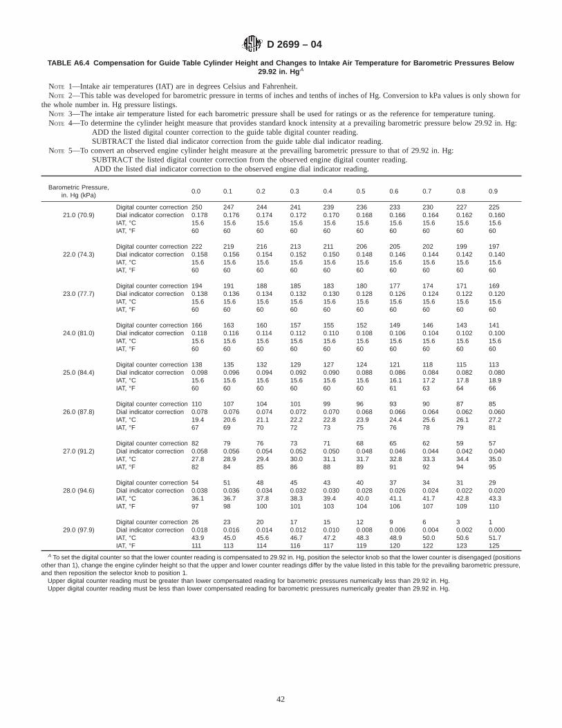
TABLE A6.4 Compensation for Guide Table Cylinder Height and Changes to Intake Air Temperature for Barometric Pressures Below29.92 in. Hg A
NOTE 1—Intake air temperatures (IAT) are in degrees Celsius and Fahrenheit.NOTE 2—This table was developed for barometric pressure in terms of inches and tenths of inches of Hg. Conversion to kPa values is only shown for
the whole number in. Hg pressure listings.NOTE 3—The intake air temperature listed for each barometric pressure shall be used for ratings or as the reference for temperature tuning.NOTE 4—To determine the cylinder height measure that provides standard knock intensity at a prevailing barometric pressure below 29.92 in. Hg:
ADD the listed digital counter correction to the guide table digital counter reading.SUBTRACT the listed dial indicator correction from the guide table dial indicator reading.
NOTE 5—To convert an observed engine cylinder height measure at the prevailing barometric pressure to that of 29.92 in. Hg:SUBTRACT the listed digital counter correction from the observed engine digital counter reading.ADD the listed dial indicator correction to the observed engine dial indicator reading.
Barometric Pressure,in. Hg (kPa)
0.0 0.1 0.2 0.3 0.4 0.5 0.6 0.7 0.8 0.9
Digital counter correction 250 247 244 241 239 236 233 230 227 22521.0 (70.9) Dial indicator correction 0.178 0.176 0.174 0.172 0.170 0.168 0.166 0.164 0.162 0.160
IAT, °C 15.6 15.6 15.6 15.6 15.6 15.6 15.6 15.6 15.6 15.6IAT, °F 60 60 60 60 60 60 60 60 60 60
Digital counter correction 222 219 216 213 211 206 205 202 199 19722.0 (74.3) Dial indicator correction 0.158 0.156 0.154 0.152 0.150 0.148 0.146 0.144 0.142 0.140
IAT, °C 15.6 15.6 15.6 15.6 15.6 15.6 15.6 15.6 15.6 15.6IAT, °F 60 60 60 60 60 60 60 60 60 60
Digital counter correction 194 191 188 185 183 180 177 174 171 16923.0 (77.7) Dial indicator correction 0.138 0.136 0.134 0.132 0.130 0.128 0.126 0.124 0.122 0.120
IAT, °C 15.6 15.6 15.6 15.6 15.6 15.6 15.6 15.6 15.6 15.6IAT, °F 60 60 60 60 60 60 60 60 60 60
Digital counter correction 166 163 160 157 155 152 149 146 143 14124.0 (81.0) Dial indicator correction 0.118 0.116 0.114 0.112 0.110 0.108 0.106 0.104 0.102 0.100
IAT, °C 15.6 15.6 15.6 15.6 15.6 15.6 15.6 15.6 15.6 15.6IAT, °F 60 60 60 60 60 60 60 60 60 60
Digital counter correction 138 135 132 129 127 124 121 118 115 11325.0 (84.4) Dial indicator correction 0.098 0.096 0.094 0.092 0.090 0.088 0.086 0.084 0.082 0.080
IAT, °C 15.6 15.6 15.6 15.6 15.6 15.6 16.1 17.2 17.8 18.9IAT, °F 60 60 60 60 60 60 61 63 64 66
Digital counter correction 110 107 104 101 99 96 93 90 87 8526.0 (87.8) Dial indicator correction 0.078 0.076 0.074 0.072 0.070 0.068 0.066 0.064 0.062 0.060
IAT, °C 19.4 20.6 21.1 22.2 22.8 23.9 24.4 25.6 26.1 27.2IAT, °F 67 69 70 72 73 75 76 78 79 81
Digital counter correction 82 79 76 73 71 68 65 62 59 5727.0 (91.2) Dial indicator correction 0.058 0.056 0.054 0.052 0.050 0.048 0.046 0.044 0.042 0.040
IAT, °C 27.8 28.9 29.4 30.0 31.1 31.7 32.8 33.3 34.4 35.0IAT, °F 82 84 85 86 88 89 91 92 94 95
Digital counter correction 54 51 48 45 43 40 37 34 31 2928.0 (94.6) Dial indicator correction 0.038 0.036 0.034 0.032 0.030 0.028 0.026 0.024 0.022 0.020
IAT, °C 36.1 36.7 37.8 38.3 39.4 40.0 41.1 41.7 42.8 43.3IAT, °F 97 98 100 101 103 104 106 107 109 110
Digital counter correction 26 23 20 17 15 12 9 6 3 129.0 (97.9) Dial indicator correction 0.018 0.016 0.014 0.012 0.010 0.008 0.006 0.004 0.002 0.000
IAT, °C 43.9 45.0 45.6 46.7 47.2 48.3 48.9 50.0 50.6 51.7IAT, °F 111 113 114 116 117 119 120 122 123 125
A To set the digital counter so that the lower counter reading is compensated to 29.92 in. Hg, position the selector knob so that the lower counter is disengaged (positionsother than 1), change the engine cylinder height so that the upper and lower counter readings differ by the value listed in this table for the prevailing barometric pressure,and then reposition the selector knob to position 1.
Upper digital counter reading must be greater than lower compensated reading for barometric pressures numerically less than 29.92 in. Hg.Upper digital counter reading must be less than lower compensated reading for barometric pressures numerically greater than 29.92 in. Hg.
D 2699 – 04
42

APPENDIXES
(Nonmandatory Information)
X1. VOLUMETRIC REFERENCE FUEL BLENDING APPARATUS AND PROCEDURES
X1.1 Background—PRFs and TSF are supplied in bulkcontainers of (0.019 or 0.208 m3) 5 and 55 U.S. gal capacity,and for laboratory safety reasons, these quantities are typicallystored in a special fuel storage room or outside of the enginelaboratory.
X1.2 Delivery from Storage—Delivery of reference fuelmaterial from the bulk storage container to a dispensingapparatus in the engine laboratory may be handled in any ofseveral ways. The equipment and procedures required fordelivery of the reference fuel materials are the responsibility ofthe user of this test method.
X1.3 Dispensing Equipment—A common means of accu-rately measuring reference fuel blend volumes applies amatched set of calibrated glass burets, one for each of the fourfuels that are the blend constituents. Fuel is dispensed eitherthrough an internal glass stopcock or a separate valve.
X1.3.1 Burets of glass with an automatic zero top fittingprovide accurate, efficient, and convenient measurement. Twostyles are commercially available; single burets having gradu-ations from 0 to 100 %, and a two-buret combination with thegraduated section of each measuring just 50 % of the batchamount.
X1.3.1.1 Single Buret Style—A glass buret with an auto-matic zero and overflow dome as illustrated in Fig. X1.1.Burets of this style are commonly fabricated in 300-, 400-, or500-mL capacities. Specifications for a typical 500-mL buretare given in Table X1.1.
X1.3.1.2 Two Buret Style—Typical burets of both types areillustrated in Fig. X1.2. Specifications for these burets appli-cable for a blend volume of 400 mL are given in Table X1.2.
(1) One type consists of an automatic zero and overflowdome, a glass half-capacity bulb, and a straight graduated
section. This buret is calibrated from 0 to 50 % on one side ofthe straight section and 50 to 100 % on the other side of thestraight section.
(2) The second type consists of an automatic zero andoverflow dome and just a straight graduated section, calibratedon one side from 0 to 50 % and on the other side from 50 to100 %.
X1.3.2 Separate Dispensing Valves—It is common practiceto utilize burets that do not have a dispensing stopcock. Bottom
TABLE A6.5 Compensation for Guide Table Cylinder Height and Changes to Intake Air Temperature for Barometric Pressures Above29.92 in. Hg A
NOTE 1—To determine the cylinder height measure that provides standard knock intensity at a prevailing barometric pressure above 29.92 in. Hg:SUBTRACT the listed digital counter correction from the guide table digital counter reading.ADD the listed dial indicator correction to the guide table dial indicator reading.
NOTE 2—To convert an observed engine cylinder height measure at the prevailing barometric pressure to that of 29.92 in. Hg:ADD the listed digital counter correction to the observed engine digital counter reading.
SUBTRACT the listed dial indicator correction from the observed engine dial indicator reading.
Barometric Pressure,in. Hg (kPa)
0.0 0.1 0.2 0.3 0.4 0.5 0.6 0.7 0.8 0.9
Digital counter correction 2 5 8 11 13 16 19 22 25 2730.0 (101.3) Dial indicator correction 0.002 0.004 0.006 0.008 0.010 0.012 0.014 0.016 0.018 0.020
IAT, °C 52.2 52.8 53.9 54.4 55.6 56.1 57.2 57.8 58.9 59.4IAT, °F 126 127 129 130 132 133 135 136 138 139
A To set the digital counter so that the lower counter reading is compensated to 29.92 in. Hg, position the selector knob so that the lower counter is disengaged (positionsother than 1), change the engine cylinder height so that the upper and lower counter readings differ by the value listed in this table for the prevailing barometric pressure,and then reposition the selector knob to position 1.
Upper digital counter reading must be greater than lower compensated reading for barometric pressures numerically less than 29.92 in. Hg.Upper digital counter reading must be less than lower compensated reading for barometric pressures numerically greater than 29.92 in. Hg.
FIG. X1.1 Typical Reference Material Dispensing Apparatus-Single Buret Style
D 2699 – 04
43

delivery from the buret is from a straight tubing bib which isconnected by plastic tubing to a three-way valve similar to thatshown in Fig. X1.3. The most important feature of such a valveassembly is the dispensing fitting that is formed so that only avery minimum of drip can occur if the collection container isinadvertently touched against the orifice tip.
X1.4 System Installation and Operation—User experiencewith reference fuel systems has pointed out a number ofimportant aspects that support the following recommendations:
X1.4.1 Install a separate buret for each reference andstandardization fuel.
X1.4.2 Mount burets vertically at an elevation that permitshorizontal sighting of all calibration marks.
X1.4.3 To minimize blending error, the dispensing system,including the buret and delivery valve, shall include a restric-tion, external to the buret, to limit the flow to no more than 400mL/min.
X1.4.4 Mount burets in a manner than ensures freedomfrom vibration.
X1.4.5 Store bulk reference fuel containers and provideappropriate tubing for delivery of the fuels to the dispensingburets in accordance with the instructions of the manufacturerand in compliance with all local codes and regulations.
X1.4.5.1 Equip bulk reference fuel containers with vacuum/pressure relief fittings to maintain container internal pressureclose to atmospheric pressure and minimize container vaporspace breathing to the atmosphere.
X1.4.5.2 Connect bulk fuel containers to dispensing buretsusing stainless steel or other opaque tubing that will not reactwith the reference fuel.
X1.4.5.3 Avoid the use of gravity flow delivery of referenceor standardization fuel to burets.
X1.4.6 Thoroughly clean burets thoroughly on a regularbasis to minimize hang-up or clinging on the inner surface ofthe buret that can lead to blending errors.
X1.4.7 Avoid filling burets until a blend is required in orderto minimize any tendency for deterioration of the fuel byexposure to light.
X1.5 Procedure for Use of Buret System:
X1.5.1 To fill the buret, set the valve or stopcock to FILLposition so that fuel rises in the buret until it overflows at theautomatic zero. Stop filling by setting the valve to OFFposition. Check that any bubbles are purged at the zero tip andrefill the tip, if necessary.
X1.5.2 To dispense fuel, set the valve to DISPENSE posi-tion so that fuel is delivered to the collection container. Stopdispensing by setting the valve to OFF position while carefullynoting the level of the fuel in the calibrated section of the buretand locating the bottom of the liquid meniscus at the desiredvolume percent mark.
X1.5.3 Before drawing a measured volume, make certainthat the tip of the dispensing tube is full. When the measuredvolume has been collected, be certain not to drain any fuelfrom the tip of the dispensing tube as this will cause an error.
TABLE X1.1 Typical Single Buret Style Specifications
Buret capacity mL 500Automatic zero YesGraduations:
Major marks % 5Minor marks % 1
Internal diameter of graduated tube:Minimum mm 32Maximum mm 34
Scale length, 5 to 100 %:Minimum mm 523Maximum mm 591
Length, top of overflow bulb to 5 % mark (nominal) mm 100/120Overall length (including tip):
Minimum mm 650Scale error (maximum) % 60.1
D 2699 – 04
44

FIG. X1.2 Typical Reference Material Dispensing Apparatus-Two Buret Style
TABLE X1.2 Typical Two Buret Style Specifications
Buret Without Half-Capacity Bulb
Buret capacity mL 200Automatic zero YesGraduations:
Left side % 0 to 50Right side % 50 to 100
Internal diameter of graduated tube:Minimum mm 21.2Maximum mm 22.5
Scale length:Minimum, 5 to 50 % and 55 to 100 % mm 450Maximum, 5 to 55 % and 55 to 100 % mm 495
Length, bottom of overflow bulb to lower end:Minimum mm 595Maximum mm 605
Scale error (maximum) % 60.1
Buret With Half-Capacity Bulb
Buret capacity mL 400Automatic zero YesOutside diameter of half-capacity bulb (approximate) mm 81Graduations on straight section:
Left side % 0 to 50Right side % 50 to 100
Internal diameter of graduated tube:Minimum mm 21.5Maximum mm 22.5
Scale length:Minimum, 5 to 50 and 55 to 100 % mm 500Maximum, 5 to 50 and 55 to 100 % mm 550
Length, bottom of half-capacity bulb to lower end:Minimum mm 620Maximum mm 630
Scale error (maximum) % 60.1
D 2699 – 04
45

X2. OPERATING TECHNIQUES—ADJUSTMENT OF VARIABLES
X2.1 Adjusting Compression Ratio—Compression ratiovaries when the cylinder is moved up and down in theclamping sleeve by means of a worm-gear drive, which isoperated either by a hand crank or by an instrument panelcontrolled gearmotor.
X2.1.1 When the unit is equipped with a hand crank, thecylinder clamping sleeve cam lever must be loosened beforecranking in either direction. To increase C.R., (lower thecylinder in the sleeve), rotate the crank in a counterclockwisedirection. To decrease C.R., rotate the crank in a clockwisedirection. After each change of cylinder position, move the camlever so that the cam flat contacts the clamping washers totighten the clamping sleeve, thereby applying a repeatablepressure on the clamping sleeve. The cam lever setting shouldmaintain constant cylinder clamp tightness regardless of theangular position of the crank after a change. Typically, with thecam in the locked position, 10 lbf-ft torque on the cam studnuts is adequate, but torque should never exceed 25 lbf-ft toavoid cylinder distortion.
X2.1.2 Units equipped with a motorized C.R. change motordo not require loosening of the cylinder clamp when a C.R.change is made. The gearmotor is equipped with a brake thatprevents worm shaft rotation unless the motor is operated. Asolenoid releases the brake when the motor is actuated in eitherdirection. Although the cam lever is unnecessary for unitsequipped with the motor changer, the clamping sleeve bolt andnut combination must be tightened slightly to prevent vibrationof the cylinder in the sleeve. A torque setting of approximately5 lbf-ft on the clamp nuts is typically effective.
X2.1.3 Measurement of cylinder height is accomplishedusing either a dial indicator assembly mounted on the cylinderand clamping sleeve or through use of the digital counter thatis driven by the worm shaft to provide a reading for eachcylinder position. These devices require indexing to a specificcylinder position each time a unit is reassembled. The dialindicator and digital counter readings are thus related to engineC.R.
X2.2 Fuel-Air Ratio Adjustment:
X2.2.1 All O.N. determinations require that the knockmeterreading of significance be that which occurs at the fuel-air ratio
that causes a maximum knock condition. This applies to bothsample fuels and reference fuel blends. Fuel-air ratio isadjusted by raising or lowering the fuel level in the carburetorvertical jet. For the typical float reservoir equipped engine, fuellevel in the sight glass is adjusted by turning the screw knob atthe bottom of the float reservoir assembly. To ensure satisfac-tory fuel atomization, it is required that the fuel level formaximum knock be between 0.7 and 1.7 on the sight glass. Ifthis is not the case, the horizontal metering jet (in the passagebetween the sight glass and selector-valve) must be changed toa different size. If the fuel level is too high, a larger orificehorizontal jet is needed, and vice versa.
X2.2.2 Use of the falling level principle, which uses a bowlof specific cross-sectional area to deliver fuel to the horizontaljet, accomplishes the same function. As the charge of fuel isconsumed, the level automatically falls and the maximumknockmeter reading can be observed. Fuel-air ratio changescan also be accomplished by maintaining a constant fuel levelto an adjustable valve installed instead of the fixed orificehorizontal jet. Opening the adjusting valve richens the mixtureand vice versa.
X2.3 Preparations Before Starting the Engine:
X2.3.1 Check the jacket coolant level in the condenser sightglass.
X2.3.2 Check the engine crankcase lubricating oil level inthe crankcase oil sight glass.
X2.3.3 Turn on the crankcase oil heater or oil heat tempera-ture controller. Normally, if the temperature controller is left onat a setting of approximately eight, the oil will stay near theproper operating temperature.
X2.3.4 Check the engine crankcase breather assembly toensure it is clean and operable.
X2.3.5 If an ice tower is used, fill the tower with ice. Thedepth of ice in the tower should not be allowed to be less than920 mm (approximately 36 in.). If an intake air refrigerationunit is used, turn the switch on.
X2.3.6 Adjust the cylinder height to ensure that the C.R. islow enough that severe knock is avoided when the engine isfiring.
FIG. X1.3 Typical Fill/Dispense Valve
D 2699 – 04
46
X2.3.7 Lightly tap the fuel selector-valve knob in a down-ward direction using a screwdriver handle or other similar tool.This will ensure the plug is not seized in the valve body whenit is necessary to rotate the valve. (Warning—Avoid attempt-ing to rotate the selector-valve knob if it resists turning.Rotation can score the plug and valve body and cause fuelleakage.)
X2.3.8 Fill one of the fuel tanks with the selected warm-upfuel, and purge any air bubbles from the tubing and sight glass.Adjust the fuel level so that the engine will operate atapproximately the fuel-air ratio for maximum K.I.
X2.3.9 Open the cooling water valve or check that coolingwater will be available for the coolant condenser when theengine is started.
X2.3.10 Check that the ignition switch is turned off.X2.3.11 Manually rotate the engine crankshaft three or four
complete revolutions to ensure that all parts move freely.Complete the cranking so that the flywheel is positioned at tdcon the compression stroke to minimize the load on thesynchronous—reluctance motor when the engine is started.
X2.4 Starting the Engine—It is assumed that the engine hasbeen commissioned and is in operable condition and thatelectrical circuits and cooling water are available on demand.
X2.4.1 Check that the fuel-selector valve is positionedbetween two bowl marks so that fuel will not enter thecarburetor initially.
X2.4.2 Position the off-run-start switch to start and hold it instart position for a few seconds to allow oil pressure to risesufficiently to actuate the engine run circuitry so that the enginecontinues to operate when the start switch is released to the runposition.
X2.4.3 Check that the temperature controller for the air/mixture heater(s) is on and functioning.
X2.4.4 Rotate the fuel selector-valve to deliver the warm-upfuel to the combustion chamber.
X2.4.5 Turn on the ignition switch so that the engine beginsto fire.
X2.4.6 As the engine begins to warm up, adjust the cylinderheight to produce a very light knock sound. As warm-upprogresses, the knock level will increase.
X2.4.7 Oil the rocker arm assembly using SAE 30 Gradeengine crankcase lubricating oil.
X2.4.8 During the warm-up period, observe the followingconditions:
X2.4.8.1 Oil pressure is steady and within specification.X2.4.8.2 Crankcase pressure indicates a slight vacuum.X2.4.8.3 Temperatures come to equilibrium within specifi-
cation.X2.4.8.4 The cylinder jacket coolant water rises in the
condenser sight glass until it is at the LEVEL HOT mark.
X2.4.8.5 Cooling water is discharged from the unit at asteady rate.
X2.4.9 As a final check before using the engine for rating,perform the following:
X2.4.9.1 Check valve clearances, hot and running, andmake any necessary adjustments.
X2.4.9.2 Check spark timing.X2.4.9.3 Switch to a PRF blend of appropriate O.N., set the
cylinder height to the guide table value, compensated forbarometric pressure, adjust the carburetor fuel level to obtainmaximum knockmeter reading, and set the detonation meterMETER READING and SPREAD dials to provide satisfactoryspread with the knockmeter reading at 50.
X2.5 Stopping the Engine:
X2.5.1 To stop the engine, turn the ignition switch to OFFand position the stop/run/start switch to STOP.
X2.5.2 Drain all fuel from the engine carburetor.X2.5.3 Using the hand crank, manually rotate the crankshaft
to position it at tdc on the compression stroke so that the intakeand exhaust valves are closed. This will minimize possiblevalve warpage or corrosion in the combustion chamber be-tween operating periods.
X2.5.4 Turn off the cooling water to the coolant condenser.
X2.6 Checking Exhaust and Crankcase Breather Systemsfor Resonance:
X2.6.1 Resonance in the piping systems can occur when theconfiguration creates a critical length/volume relationship. Aresonant condition affects the primary pressure within thesystem and can affect critical operating conditions.
X2.6.2 Exhaust system resonance may be checked by pro-viding either a3⁄4-in. or larger gate or ball valve at the exhaustsurge tank or close to the engine exhaust port. Opening thevalve should drastically change the exhaust discharge configu-ration while the engine is operating at standard conditions ifresonance is occurring.
X2.6.2.1 Operate the engine at standard conditions on atypical sample or reference fuel and allow sufficient time forthe knockmeter reading to stabilize. Observe the knockmeterreading.
X2.6.2.2 Open the valve or affect the change in exhaustpiping while the engine continues to operate.
X2.6.2.3 If the knockmeter reading is not affected, reso-nance does not occur and the piping system is satisfactory.
X2.6.2.4 If the knockmeter reading is affected when thevalve is opened, resonance may be a factor and typically achange in the length of the exhaust discharge pipe will correctthe condition.
X2.6.3 Crankcase breather system resonance typicallycauses the crankcase pressure to be positive. Resonance in thedischarge piping is not a problem as long as the operatingengine creates a crankcase vacuum.
D 2699 – 04
47

X3. MAINTENANCE TECHNIQUES
X3.1 Importance of Maintenance—The need for propermaintenance of the knock testing unit cannot be overempha-sized if reliable O.N. ratings of sample fuels are to be obtained.The care used in the inspection, adjustment, and especially theoverhaul of the combustion chamber components is a majorfactor in achieving these aims.
X3.2 Types of Maintenance:
X3.2.1 Daily Checks—Those checks associated with thepreparations before starting the engine as detailed in AppendixX2.
X3.2.2 Top Overhaul, generally accepted term used todescribe valve reconditioning, the cleaning of the combustionchamber, piston, and piston rings, and the cleaning of thecoolant jacket passages and the coolant condenser. Some otherparts may also be given attention during a top overhaul,depending on need.
X3.2.3 Crankcase/Unit Inspection—Encompasses crank-case cleaning, mechanical component wear checks, alarmfunction checks, power absorption motor inspection, belttension adjustment, instrumentation checks, and so forth.
X3.2.3.1 The recommended interval between crankcase/unitinspections is every 2000 h of operation or biannually, which-ever comes first. Model CFR-48 crankcases can be completelyrestored by the manufacturer. (Warning—Deactivate the en-gine unit before performing any maintenance. Shut off electri-cal power at the main disconnect, lock out, if possible. Place aWARNING notice on the unit panel indicating repairs are inprocess and that no attempt is to be made to start the engine.Shut off coolant water to the unit.)
X3.2.4 Auxiliary Equipment Maintenance—Volumetricglassware such as reference fuel blending burets should bechemically cleaned on a regular basis to ensure accuratevolumetric measurement.
X3.2.4.1 Quarterly cleaning of volumetric apparatus is rec-ommended.
X3.2.5 Carbon Blasting—Combustion chamber depositscan be effectively removed by carbon blasting without removalof the cylinder from the engine. Performed on a regular basisbetween top overhauls, this technique effectively extends theperiod of time between these mechanical overhauls.26
X3.2.5.1 Blasting is done through the intake and exhaustports and the spark plug hole. The return line for removal of thedeposits and spent blasting material is attached to the hole forthe detonation pickup.
X3.2.5.2 Complete blasting procedure instructions are in-cluded with the carbon blasting kit and all phases of theprocedure should be carried out for effective results.
X3.3 Top Overhaul Procedures:
X3.3.1 Disassemble the complete cylinder/clamping sleeveassembly from the engine crankcase. Components to be re-moved include:
X3.3.1.1 Detonation pickup, spark plug, all thermometersand temperature sensors.
X3.3.1.2 C.R. gearmotor assembly from the clampingsleeve. If a dial indicator is in use, remove it from the cylinder.
X3.3.1.3 All intake air system components, the carburetor,and the carburetor heat shield.
X3.3.1.4 Cooling water lines at the coolant condenser andthe exhaust pipe.
X3.3.1.5 Disconnect the applicable exhaust system compo-nents from the cylinder exhaust port.
X3.3.1.6 Coolant condenser and water return pipe from thecylinder assembly.
X3.3.1.7 Disconnect the spark advance bracket, if it is onthe unit.
X3.3.1.8 Loosen the long rocker arm support bolts thatfasten the support to the clamping sleeve. Remove the valvehalf-balls. Remove the push rods.
NOTE X3.1—Marking of push rods as intake and exhaust ensures theywill be reassembled in the same positions.
X3.3.1.9 Cylinder and clamping sleeve as an assembly afterremoval of the five clamping sleeve stud nuts.
X3.3.1.10 Piston from connecting rod.X3.3.2 Separate the cylinder from the clamping sleeve as
follows:X3.3.2.1 Remove the two bolts from the long rocker arm
support and separate the support from the clamping sleeve.X3.3.2.2 Remove the water inlet pipe assembly from the
cylinder.X3.3.2.3 Remove the cylinder from the clamping sleeve.X3.3.3 Disassemble the valve tapers, retainer and rotator
assembly, springs, and valves from the cylinder. Remove theroll pin from the intake valve stem to remove this valve.
X3.3.4 Component Cleaning—All combustion deposits,gasket material, rust, and so forth should be removed fromcomponents.
X3.3.4.1 Commercial chemical cleaning solutions may beused in accordance with manufacturer’s instructions as long asthey do not etch or affect the surface finish of the machinedsurfaces. Except for the detonation pickup and temperaturesensors, use of ultrasonic bath equipment has been demon-strated to be effective and the heating of some cleaningsolutions can also be beneficial. (Warning—Chemical clean-ing solutions are poisonous and may be harmful or fatal ifinhaled or swallowed. See Annex A1.)
X3.3.4.2 Scraping, brass wire brushes (manually or powerdriven), and fine steel wool have been found to be effectivecleaning aids.
X3.3.4.3 Complete any cleaning sequence by rinsing of allparts with a solvent.
X3.3.5 Cylinder:X3.3.5.1 Check the cylinder bore diameter at the top,
middle, and bottom areas of ring travel in two planes, which
26 A carbon blaster kit specific for CFR engine units is available from WaukeshaEngine Division, Dresser Industries, Inc., 1000 St. Paul Avenue, Waukesha, WI53188.
D 2699 – 04
48

are 90° apart. Replace the cylinder if the internal diameter atthe area of maximum wear is more than 0.006 in. larger thanthe unworn skirt internal diameter. Replace the cylinder if thebore is out-of-round in excess of 0.0025 in.
X3.3.5.2 Cylinders rebored to 0.010, 0.020, and 0.030 in.larger than the original 3.250-in. diameter are permitted and thesame wear limits apply based on the unworn skirt diameter ofthe rebore.
X3.3.5.3 Valve Guides—Replace a guide when the internaldiameter exceeds the wear limit. Replacement requires specialtools.
X3.3.5.4 Valves—Replace if stem is badly scuffed or stemdiameter is less than the replacement limit. Reface to 45° usinga valve refacing (grinding) machine so that face run-out is lessthan 0.0015 in. Replace the valve if grinding has created amargin of less than1⁄32 in.
X3.3.5.5 Valve Seats—Reface seats using a valve seatgrinding machine or a valve seat cutter kit. Use a 45° seat angleand subsequently lap the valve to the seat. Alternatively, aninterference angle approach may be utilized by refacing theseat at both 46° and 15° so that the intersecting line becomesthe contact surface with a 45° faced valve. When an interfer-ence angle approach is utilized, lapping may be performed butextreme care must be taken to exert very light pressure toprevent creating a groove in the valve face.
X3.3.5.6 Valve to Valve Seat Match-up—Check the valve toseat contact. Lapped valve seat width must not exceed 0.070 in.as viewed on the valve. The top edge of the contact line or areashall be at least 0.030 in. from the top edge of the faced portionof the valve.
X3.3.5.7 Valve Rotators—Inspect the races which shouldrotate freely so that, when the engine is operating, the valverotates at approximately 1 to 2 rpm.
X3.3.5.8 Valve Reassembling—Install valves in the cylinderwith felt lubrication washers, springs, retainer (intake), rotatorassembly (exhaust) and tapers. Carefully install the intakevalve with the opening of the shroud facing the pickup holebefore inserting the roll pin into the valve stem through the slotin the valve guide. Install valve springs with closely woundcoils next to the cylinder oil tray.
X3.3.5.9 Rocker Arm Assembly:(1) Inspect each rocker for excessive bearing wear or
wobble on the rocker shaft.(2) Inspect the rocker adjusting screws for galled ball ends
and also for damaged Phillips screwdriver slots.(3) Inspect the rocker ball sockets for wear or galling.(4) Replace any worn or out of specification parts.
X3.3.6 Piston and Rings:X3.3.6.1 Replace the piston if there is evidence of scoring
or a wear pattern.X3.3.6.2 Replacement of all rings at the time of every
overhaul is typical. A chrome-plated top compression ring maybe reused for several overhaul periods.
X3.3.6.3 Ring gaps should be checked by feeler gage withthe ring inserted in the skirt end of the cylinder. The pistonshould be used to square the ring in the bore about 1 in. beyondthe chamfer. Rings should be replaced if the gap exceeds thereplacement limit.
X3.3.6.4 Ring-to-land clearances should be checked, usinga feeler gage, after the rings are assembled on the piston.Replace the piston if the clearances exceed the tolerance limits.
X3.3.6.5 Replace the piston pin if scoring or wear marks areobserved on the pin.
X3.3.7 Clamping Sleeve:X3.3.7.1 Check that the internal bore of the sleeve is within
tolerance.X3.3.7.2 Check that the counterbore for the worm wheel is
within tolerance.X3.3.7.3 Insert the worm wheel in the clamping sleeve and
check that the distance between the worm wheel face and thatof the bottom of the sleeve is within tolerance.
X3.3.7.4 Inspect the worm shaft ball and thrust bearings andreplace as required.
X3.3.8 Cylinder Guide Plate:X3.3.8.1 Inspect the wear surface that contacts the worm
wheel. Replace the guide plate if there is wear or scoring.X3.3.9 Condenser and Cooling System:X3.3.9.1 Inspect the inner surfaces of the condenser and the
baffle tube for rust or scale deposits, wipe out the cavity, andrinse with hot water prior to assembly.
X3.3.9.2 Inspect the cooling coil, clean surface deposits,and observe that the coils are slightly separated from each otherto maximize the cooling surface exposed to coolant steam.
X3.3.9.3 Chemical cleaning of coolant system surfacesshould take place whenever significant deposits are observed orat least at every third top overhaul. One approach is tointroduce a commercial cooling system cleaner in the coolingsystem after reassembly of the engine. By running the enginefor intermittent periods, the solution can be heated to 80 to90°C (180 to 200°F). The solution should be kept at thistemperature for approximately 30 min and drained. The systemshould then be flushed with clean hot water before rechargingwith a rust inhibited coolant water. (Warning—Chemicalcleaning solutions are poisonous and may be harmful or fatal ifinhaled or swallowed. See Annex A1.)
X3.3.10 Reassembly Procedures:X3.3.10.1 Install the piston, piston pin, and pin retainers on
the connecting rod. Lubricate the rings with SAE 30 Gradeengine crankcase oil.
X3.3.10.2 Reassemble the cylinder in the clamping sleeveso that the skirt of the cylinder extends at least 6 mm (1⁄4 in.)past the bottom of the sleeve. Check that the proper number ofworm shaft shims are used so that the worm shaft end play isminimal (typically 1⁄8 turn of the shaft).
X3.3.10.3 Connect the long rocker arm support to theclamping sleeve.
X3.3.10.4 Assemble the cylinder guide plate with its gas-kets on the crankcase.
X3.3.10.5 Rigidly support the piston above the crankcaseand guide plate. Install the cylinder/clamping sleeve assemblyover the piston so that it is seated on the crankcase. Care shouldbe taken not to break any of the rings as they enter thechamfered bore. (Use of a ring compressor tool over the pistonrings is advisable despite the cylinder chamfer.) Manuallyrotate the crankshaft through several revolutions so that the
D 2699 – 04
49

cylinder is centered. Tighten and torque the cylinder stud nutsas specified in Table A4.1.
X3.3.10.6 Manually rotate the crankshaft so that the pistonis at top-dead-center on the compression stroke as indicated bythe flywheel pointer.
X3.3.10.7 Install the marked push rods and the valvehalf-balls. Reposition the long rocker arm support as required,tighten the support bolts, and check that the rocker carrier androcker arms are level.
X3.3.10.8 Set the valve clearances to 0.075 mm (0.004 in.)for the intake valve and 0.330 mm (0.014 in.) for the exhaustvalve.
X3.3.10.9 Connect the appropriate exhaust system compo-nents to the cylinder exhaust port.
X3.3.10.10 Install the water inlet pipe, water return pipe, thecoolant condenser, and the cooling water lines.
X3.3.10.11 Install the C.R. gearmotor assembly and the dialindicator assembly, if used.
X3.3.10.12 Install the carburetor heat shield, carburetor, andall intake air system components.
X3.3.11 Crankcase Breather:X3.3.11.1 Disconnect the breather pipe and remove the
breather assembly from the engine crankcase.X3.3.11.2 Unscrew the cap from the body, remove the
plastic cup, and clean the emulsion deposits from all of thepieces.
X3.3.11.3 Inspect the cup, and if the surface of the openedge is rounded rather than square, replace the cup.
X3.3.11.4 Rinse the components using a petroleum basedsolvent or kerosine and reassemble them on the engine.(Warning—Petroleum based solvent is flammable and itsvapors are harmful if inhaled. Vapors may cause flash fire. SeeAnnex A1.) (Warning—Kerosine is combustible and its va-pors are harmful. See Annex A1.)
X3.3.12 Crankcase Oil Change:X3.3.12.1 Drain the used oil and add new SAE 30 Grade
engine crankcase lubricating oil.X3.3.12.2 It is recommended that the crankcase lubricating
oil be changed at intervals of approximately 50 h of engineoperation and at the time of each top overhaul.
X3.3.12.3 It is recommended that the oil filter cartridge bechanged at the time of every other oil change.
X3.4 Engine Starting Preparations:
X3.4.1 See Appendix X2.
X3.5 Crankcase/Unit Inspection:
X3.5.1 Crankcase—Inspect the crankcase periodically asfollows:
X3.5.1.1 Turn off the electrical power circuits to the engineand unit.
X3.5.1.2 Drain the crankcase lubricating oil and clean thecrankcase sump using a petroleum based solvent.
X3.5.1.3 Disassemble the oil suction screen assembly andclean the components.
X3.5.1.4 Disassemble the crankcase breather body from thecrankcase door and clean the internal passage and baffles.
X3.5.1.5 Disassemble the connecting rod from the crank-shaft. Inspect the big end bearing shells and replace if wear isindicated. Reassemble the connecting rod and torque the capbolts as specified in Annex A4, Table A4.1.
X3.5.1.6 Disassemble the valve lifters from the top of thecrankcase, clean, inspect, and if necessary, replace wornassembly components.
X3.5.1.7 Approximate the rear main bearing clearance bydial indicator measurement of the movement of the crankcaseedge of the flywheel outer surface. Measure with the flywheelat rest and then with the flywheel lifted using an appropriatelever. If the difference in the measurements exceeds 0.15 mm(0.006 in.), crankcase rebuilding is recommended.
X3.5.1.8 Disassemble the oil pressure control valve assem-bly, solvent clean, inspect for worn components, and replace asrequired. (Warning—In addition to other precautions, avoidover tightening the four control valve body fastening bolts toprevent valve body distortion and restriction of the plungermovement.)
X3.5.1.9 Inspect the outer crankcase surfaces for indicationsof oil seal leakage which may require extensive maintenance orcrankcase rebuilding.
X3.5.2 Power Absorption Motor—Inspect the power ab-sorption motor annually as follows:
X3.5.2.1 Turn off all the electrical power circuits to theengine and unit.
X3.5.2.2 Check the condition and tension of the drive belts.Replace belts as required and adjust the motor position toachieve proper belt tension.
X3.5.2.3 Remove dust and dirt from the end bell openingsusing low pressure compressed air.
X3.5.3 Safety Cutoff Checks:X3.5.3.1 High Coolant Temperature Switch—After shutting
off the cooling water to the condenser coil, the engine shouldstop within 1 min. Check and adjust the thermal switch setpoint as required.
X3.5.3.2 Low Oil Pressure Switch—When starting the en-gine, release of the momentary start switch before the oilpressure reaches approximately 20 psi (138 kPa), should resultin unit shut down.
X3.5.3.3 Electrical Interlock—Disconnecting either thesingle phase or three phase power at the appropriate supplyswitch should cause unit shut down.
D 2699 – 04
50

SUMMARY OF CHANGES
Subcommittee D02.01 has identified the location of selected changes to this standard since the last issue(D 2699–03a) that may impact the use of this standard. (Approved May 1, 2004.)
(1) Clarified the requirements for temperature tuning in 11.3.3and 11.3.5.
(2) Corrected the cylinder position for basic rocker arm carriersetting in 10.3.14.2.
Subcommittee D02.01 has identified the location of selected changes to this standard since the last issue (D 2699–03) thatmay impact the use of this standard. (Approved Aug. 10, 2003.)
(1) Added 11.3.2.1 on IAT tuning.
Subcommittee D02.01 has identified the location of selected changes to this standard since the last issue (D 2699–02) thatmay impact the use of this standard. (Approved June 10, 2003.)
(1) Revised 7.3.1 to allow for gravimetric blending of referencefuels.
(2) Revised A1.1.1, A1.2, A1.3, and A1.4.(3) Revised X1.4 for clarity and emphasis.
ASTM International takes no position respecting the validity of any patent rights asserted in connection with any item mentionedin this standard. Users of this standard are expressly advised that determination of the validity of any such patent rights, and the riskof infringement of such rights, are entirely their own responsibility.
This standard is subject to revision at any time by the responsible technical committee and must be reviewed every five years andif not revised, either reapproved or withdrawn. Your comments are invited either for revision of this standard or for additional standardsand should be addressed to ASTM International Headquarters. Your comments will receive careful consideration at a meeting of theresponsible technical committee, which you may attend. If you feel that your comments have not received a fair hearing you shouldmake your views known to the ASTM Committee on Standards, at the address shown below.
This standard is copyrighted by ASTM International, 100 Barr Harbor Drive, PO Box C700, West Conshohocken, PA 19428-2959,United States. Individual reprints (single or multiple copies) of this standard may be obtained by contacting ASTM at the aboveaddress or at 610-832-9585 (phone), 610-832-9555 (fax), or [email protected] (e-mail); or through the ASTM website(www.astm.org).
D 2699 – 04
51