Embed Size (px)
Citation preview

VINEYARD TOWN DESIGN STANDARDS AND SPECIFICATIONS CHAPTER 4, TABLE OF CONTENTS
ADOPTED FEBRUARY 2007 4-i
STANDARD SPECIFICATIONS
TABLE OF CONTENTS
DIVISION 1 GENERAL REQUIREMENTS.......................................................................................................4-1
Section 1.01 PURPOSE OF DOCUMENTS......................................................................................4-1 Section 1.02 PERMIT, FEES AND BONDING REQUIRED ...........................................................4-1
Sub-Section A. Permit Application...........................................................................................4-1 Sub-Section B. Fee Assessment:...............................................................................................4-1
Section 1.03 CONTRACTOR AND CONSTRUCTION PLAN APPROVAL..................................4-1 Section 1.04 PRE-CONSTRUCTION CONFERENCE.....................................................................4-2 Section 1.05 TIMELY COMPLIANCE WITH THE ISSUED PERMIT...........................................4-2
Sub-section A. Inspections:......................................................................................................4-2 Sub-section B. Notification of Needed Inspections: ................................................................4-3 Sub-section C. Responsibility of the Owner: ...........................................................................4-3 Sub-section D. Definition of “Public Works Representative/Engineer”: .................................4-3 Sub-section E. Conflict:...........................................................................................................4-3
Section 1.06 ELECTRONIC AND RECORD DRAWINGS..............................................................4-3 Section 1.07 TEMPORARY SERVICES...........................................................................................4-3 Section 1.08 CODES AND STANDARDS........................................................................................4-3 Section 1.09 STATE AND LOCAL LAWS.......................................................................................4-3 Section 1.10 COMPLIANCE WITH GOVERNMENTAL REGULATIONS ...................................4-4
Sub-section A. United States Occupational Safety and Health Administration
Regulations:.......................................................................................4-4 Sub-section B. Utah State Industrial Commission Regulations: ..............................................4-4 Sub-section C. Ordinances:.....................................................................................................4-4 Sub-section D. UDOT Requirements:......................................................................................4-4 Sub-section E. Permits:............................................................................................................4-4
Section 1.11 FEDERAL, STATE, AND LOCAL INSPECTING AGENCIES..................................4-4 Section 1.12 PUBLIC SAFETY AND CONVENIENCE ..................................................................4-4
Sub-section A. Compliance with Rules and Regulations: ........................................................4-5 Sub-section B. Road Closures and Obstructions:.....................................................................4-5 Sub-section C. Protection of the Traveling Public:..................................................................4-5 Sub-section D. Hazardous Conditions: ....................................................................................4-5 Sub-section E. Dust and Debris Control: .................................................................................4-5
Section 1.13 CONFINEMENT OF WORK AND ACCESS TO RIGHT-OF-WAY AND
EASEMENTS .................................................................................................4-5 Section 1.14 NOTIFICATION OF RESIDENTS...............................................................................4-6 Section 1.15 WEATHER CONDITIONS ..........................................................................................4-6 Section 1.16 LAND MONUMENTS..................................................................................................4-6 Section 1.17 SOURCE OF MATERIALS..........................................................................................4-6 Section 1.18 OPERATION AND MAINTENANCE MANUALS.....................................................4-6 Section 1.19 INTERFERING STRUCTURES, UTILITIES AND FACILITIES ..............................4-6 Section 1.20 MATERIAL AND COMPACTION TESTING ............................................................4-7 Section 1.21 TELEVISING SEWER MAINS....................................................................................4-7
DIVISION 2 TRENCH EXCAVATION AND BACKFILL .................................................................................4-8
Section 2.01 GENERAL.....................................................................................................................4-8 Section 2.02 BARRICADES ..............................................................................................................4-8 Section 2.03 BLASTING....................................................................................................................4-8 Section 2.04 SHEETING, BRACING AND SHORING OF EXCAVATIONS.................................4-8 Section 2.05 CONTROL OF GROUNDWATER ..............................................................................4-8 Section 2.06 TRENCH EXCAVATION ............................................................................................4-9

VINEYARD TOWN DESIGN STANDARDS AND SPECIFICATIONS CHAPTER 4, TABLE OF CONTENTS
ADOPTED FEBRUARY 2007 4-ii
Sub-section A. Normal Excavation: .........................................................................................4-9 Sub-section B. Authorized Over-Excavation: ..........................................................................4-9 Sub-section C. Unauthorized Over-Excavation: ......................................................................4-9 Sub-section D. Trench Width:..................................................................................................4-9 Sub-section E. Trenches in Embankments:..............................................................................4-9 Sub-section F. Placement of Excavated Material: ...................................................................4-10 Sub-section G. Fine Grading the Trench Bottom:....................................................................4-10
Section 2.07 TRENCH BACKFILL...................................................................................................4-10 Sub-section A. Imported Granular Material:............................................................................4-10 Sub-section B. Foundation Placement: ....................................................................................4-11 Sub-section C. Pipe Embedment:.............................................................................................4-11 Sub-section D. Final Backfill: ..................................................................................................4-11 Sub-section E. Compaction: ....................................................................................................4-11
Section 2.08 TRENCH CROSSINGS AND EASEMENTS...............................................................4-12 Section 2.09 RESTORATION OF CONSTRUCTION SITE ............................................................4-12 Section 2.10 OWNER/CONTRACTOR'S RESPONSIBILITY .........................................................4-13
DIVISION 3A PRESSURE PIPE CULINARY WATER....................................................................................4-23
Section 3A.01 GENERAL.....................................................................................................................4-23 Section 3A.03 PVC PIPE ......................................................................................................................4-24
Sub-section A. Materials:.........................................................................................................4-24 Sub-section B. Joints: ..............................................................................................................4-24 Sub-section C. Fittings:............................................................................................................4-24 Sub-section D. Caution Tape: ..................................................................................................4-25
Sub-section E. Tracer Wire: ....................................................................................................4-25
Section 3A.04 PIPE INSTALLATION .................................................................................................4-25 Sub-section A. Cutting: ............................................................................................................4-25 Sub-section B. Dewatering of Trench:.....................................................................................4-25 Sub-section C. Laying of Pipe: ................................................................................................4-25 Sub-section D. Pipe Bedding: ..................................................................................................4-26 Sub-section E. Thrust Blocking: ..............................................................................................4-26 Sub-section F. Connections to Existing Water Lines: .............................................................4-26
Section 3A.05 WATER SERVICE LATERALS ..................................................................................4-26 Sub-section A. Extent of Laterals: ...........................................................................................4-26 Sub-section B. Excavation and Backfill:..................................................................................4-26 Sub-section C. Connection to Main: ........................................................................................4-26 Sub-section D. Meter Setter, Box and Cover: ..........................................................................4-27 Sub-section E. Special Joints and Fittings: ..............................................................................4-27 Sub-section F. Separation:.......................................................................................................4-27 Sub-section G. Flushing, Testing and Disinfecting: .................................................................4-27 Sub-section H. Damage and Repair of Water Mains and Appurtenances: ...............................4-27
Section 3A.06 FLUSHING, DISINFECTING, AND TESTING ..........................................................4-28 Sub-section A. Flushing: ..........................................................................................................4-28 Sub-section B. Disinfection: ....................................................................................................4-28 Sub-section C. Pressure Test: ..................................................................................................4-29 Sub-section D. Leakage Test:...................................................................................................4-30 Sub-section E. Acceptance of Installation: ..............................................................................4-30
DIVISION 4 CONCRETE PIPE ...........................................................................................................................4-31
Section 4.01 GENERAL.....................................................................................................................4-31 Section 4.02 PIPE...............................................................................................................................4-31
Sub-section A. Reinforced Concrete Pipe:...............................................................................4-31 Sub-section B. Non-Reinforced Concrete Pipe:.......................................................................4-31 Sub-section C. Bell and Spigot Joints:.....................................................................................4-31

VINEYARD TOWN DESIGN STANDARDS AND SPECIFICATIONS CHAPTER 4, TABLE OF CONTENTS
ADOPTED FEBRUARY 2007 4-iii
Sub-section D. Minimum Size and Slope Requirements:.........................................................4-31 Section 4.03 PIPE LAYING...............................................................................................................4-32 Section 4.04 GRAVEL FOUNDATION FOR PIPE ..........................................................................4-32 Section 4.05 INSTALLATION REQUIREMENTS FOR LINE AND GRADE................................4-32 Section 4.06 PIPE BEDDING............................................................................................................4-32 Section 4.07 TESTS ...........................................................................................................................4-33
Sub-section A. Displacement Test: ..........................................................................................4-33 Sub-section B. Infiltration Test:...............................................................................................4-33 Sub-section C. Exfiltration Test:..............................................................................................4-33 Sub-section D. Air Testing:......................................................................................................4-34
Section 4.08 MANHOLE CONNECTIONS ......................................................................................4-34 Section 4.09 SEWER SERVICE LATERALS ...................................................................................4-34
Sub-section A. Extent and Location of Laterals:......................................................................4-34 Sub-section B. Excavation and Backfill:..................................................................................4-34 Sub-section C. Pipe:.................................................................................................................4-34 Sub-section D. Connection to Main: ........................................................................................4-35 Sub-section E. Cover Over Sewer Lateral Lines: ....................................................................4-35 Sub-section F. Sewer Clean Outs: ...........................................................................................4-35 Sub-section G. Testing:............................................................................................................4-35 Sub-section H. Damage and Repair of Sewers and Appurtenances: ........................................4-35
DIVISION 4A PVC PLASTIC PIPE ....................................................................................................................4-36
Section 4A.01 GENERAL.....................................................................................................................4-36 Section 4A.02 PIPE...............................................................................................................................4-36
Sub-section A. Minimum Size and Slope Requirements:.........................................................4-36 Section 4A.03 FITTINGS .....................................................................................................................4-36 Section 4A.04 PIPE LAYING...............................................................................................................4-36 Section 4A.05 GRAVEL FOUNDATION FOR PIPE ..........................................................................4-37 Section 4A.06 INSTALLATION REQUIREMENTS FOR LINE AND GRADE................................4-37 Section 4A.07 PIPE BEDDING............................................................................................................4-37 Section 4A.08 TESTS ...........................................................................................................................4-37
Sub-section A. Displacement Test: ..........................................................................................4-38 Sub-section B. Infiltration Test:...............................................................................................4-38 Sub-section C. Exfiltration Test:..............................................................................................4-38 Sub-section D. Air Testing:......................................................................................................4-38
Section 4A.09 MANHOLE CONNECTIONS ......................................................................................4-38 Section 4A.10 SEWER LATERAL CONNECTIONS..........................................................................4-39 Section 4A.11 SEWER SERVICE LATERALS ...................................................................................4-39
Sub-section A. Extent of Laterals and Location of Laterals:....................................................4-39 Sub-section B. Excavation and Backfill:..................................................................................4-39 Sub-section C. Pipe:.................................................................................................................4-39 Sub-section D. Connection to Main: ........................................................................................4-39 Sub-section E. Cover Over Sewer Lateral Lines: ....................................................................4-39 Sub-section F. Sewer Clean Outs: ...........................................................................................4-39 Sub-section G. Testing:............................................................................................................4-40 Sub-section H. Damage and Repairs of Sewers and Appurtenances:.......................................4-40
Section 4A.12 "GO/NO-GO" MANDREL PROOF TESTING ............................................................4-40
DIVISION 4B POLYETHYLENE CORRUGATED PIPE ................................................................................4-41
Section 4B.01 GENERAL.....................................................................................................................4-41 Section 4B.02 PIPE...............................................................................................................................4-41 Section 4B.03 JOINTS..........................................................................................................................4-41 Section 4B.04 PERFORATIONS..........................................................................................................4-41 Section 4B.05 PIPE LAYING...............................................................................................................4-42

VINEYARD TOWN DESIGN STANDARDS AND SPECIFICATIONS CHAPTER 4, TABLE OF CONTENTS
ADOPTED FEBRUARY 2007 4-iv
Section 4B.06 GRAVEL FOUNDATION FOR PIPE ..........................................................................4-42 Section 4B.07 INSTALLATION REQUIREMENTS FOR LINE AND GRADE................................4-42 Section 4B.08 PIPE BEDDING............................................................................................................4-42 Section 4B.09 TESTS ...........................................................................................................................4-43
Sub-section A. Displacement Test: ..........................................................................................4-43 Section 4B.10 MANHOLE CONNECTIONS .....................................................................................4-43 Section 4B.11 LATERAL CONNECTIONS .......................................................................................4-43
DIVISION 4C POLYETHYLENE CORRUGATED PIPE WITH WATER TIGHT JOINTS.......................4-44
Section 4C.01 GENERAL.....................................................................................................................4-44 Section 4C.02 PIPE...............................................................................................................................4-44 Section 4C.03 FITTINGS .....................................................................................................................4-44 Section 4C.04 PIPE LAYING...............................................................................................................4-44 Section 4C.05 GRAVEL FOUNDATION FOR PIPE ..........................................................................4-45 Section 4C.06 INSTALLATION REQUIREMENTS FOR LINE AND GRADE................................4-45 Section 4C.07 PIPE BEDDING............................................................................................................4-45 Section 4C.08 TESTS ...........................................................................................................................4-46
Sub-section A. Displacement Test: ..........................................................................................4-46 Sub-section B. Infiltration Test:...............................................................................................4-46 Sub-section C. Ex-filtration Test: ............................................................................................4-46 Sub-section D. Air Testing:......................................................................................................4-46
Section 4C.09 MANHOLE CONNECTIONS ......................................................................................4-47 Section 4C.10 LATERAL CONNECTIONS .......................................................................................4-47 Section 4C.11 "GO/NO-GO" MANDREL PROOF TESTING ...........................................................4-47
DIVISION 5 MANHOLES ....................................................................................................................................4-48
Section 5.01 GENERAL.....................................................................................................................4-48 Section 5.02 CONCRETE BASE .......................................................................................................4-48 Section 5.03 WALL AND CONE SECTIONS...................................................................................4-48
Sub-section A. Manholes Shall Be Furnished With Steps: ......................................................4-49 Section 5.04 DROP MANHOLES......................................................................................................4-49
Sub-section A. Cement:............................................................................................................4-49 Sub-section B. Fly Ash: ...........................................................................................................4-49 Sub-section C. Fine Aggregate: ...............................................................................................4-49 Sub-section D. Mix Design: .....................................................................................................4-49
Section 5.05 MANHOLE RINGS AND COVERS ............................................................................4-50 Sub-section A. Setting of Manhole Frames and Covers and Placement of Concrete
Collars .........................................................................................................................4-50 Section 5.06 CONNECTIONS TO EXISTING SEWER...................................................................4-50 Section 5.07 INCOMING SEWER LINES ........................................................................................4-50
DIVISION 6 VALVES, COUPLINGS, AND FIRE HYDRANTS......................................................................4-51
Section 6.01 GENERAL.....................................................................................................................4-51 Section 6.02 RESILIENT SEATED GATE VALVE.........................................................................4-51 Section 6.03 BUTTERFLY VALVE..................................................................................................4-52 Section 6.04 VALVE BOXES............................................................................................................4-52 Section 6.05 COUPLINGS.................................................................................................................4-53 Section 6.06 FIRE HYDRANTS........................................................................................................4-53 Section 6.07 BLOWOFF VALVE......................................................................................................4-53 Section 6.08 2-INCH AIR INLET AND REMOVAL FACILITY.....................................................4-53
DIVISION 7 EARTHWORK ................................................................................................................................4-55
Section 7.01 GENERAL.....................................................................................................................4-55

VINEYARD TOWN DESIGN STANDARDS AND SPECIFICATIONS CHAPTER 4, TABLE OF CONTENTS
ADOPTED FEBRUARY 2007 4-v
Section 7.02 EXCAVATION FOR STRUCTURES ..........................................................................4-55 Section 7.03 GRANULAR FOUNDATION BORROW....................................................................4-55 Section 7.04 BACKFILL AROUND STRUCTURES........................................................................4-55 Section 7.05 CONSTRUCTION OF EMBANKMENTS AND FILLS..............................................4-55
Sub-section A. Foundation Preparation: ..................................................................................4-55 Sub-section B. Placement: .......................................................................................................4-56 Sub-section C. Borrow:............................................................................................................4-56
Section 7.06 COMPACTION OF MATERIALS ...............................................................................4-57 Sub-section A. Under Roadways: ............................................................................................4-57 Sub-section B. Under Sidewalks and Driveways: ....................................................................4-57
Section 7.07 REMOVAL AND PLACEMENT OF DEFECTIVE FILL ...........................................4-57
DIVISION 8 PORTLAND CEMENT CONCRETE............................................................................................4-58
Section 8.01 GENERAL.....................................................................................................................4-58 Section 8.02 MATERIALS.................................................................................................................4-58
Sub-section A. Portland Cement: .............................................................................................4-58 Sub-section B. Aggregate: .......................................................................................................4-58 Sub-section C. Water: ..............................................................................................................4-59 Sub-section D. Air-Entraining Agent: ......................................................................................4-59 Sub-section E. Steel Reinforcement: .......................................................................................4-59 Sub-section F. Water-Reducing and Set-Retarding Admixtures: ............................................4-59 Sub-section G. Curing compound: ...........................................................................................4-59
Section 8.03 CLASS OF CONCRETE...............................................................................................4-60 Section 8.04 COMPOSITION OF CONCRETE................................................................................4-60
Sub-section A. Aggregate: .......................................................................................................4-60 Sub-section B. Water: ..............................................................................................................4-60 Sub-section C. Air-Content:.....................................................................................................4-60 Sub-section D. Admixtures: .....................................................................................................4-60
Section 8.05 DESIGN OF THE CONCRETE MIX ...........................................................................4-61 Section 8.06 OBSERVATION AND TESTING................................................................................4-61 Section 8.07 HANDLING AND MEASUREMENT OF MATERIALS............................................4-61 Section 8.08 MIXERS AND MIXING...............................................................................................4-61 Section 8.09 FORMS..........................................................................................................................4-62 Section 8.10 PREPARATION OF FORMS AND SUBGRADE........................................................4-62 Section 8.11 CONVEYING................................................................................................................4-62 Section 8.12 PLACING......................................................................................................................4-62 Section 8.13 CONSTRUCTION JOINTS ..........................................................................................4-63 Section 8.14 EXPANSION AND CONTRACTION JOINTS ...........................................................4-63 Section 8.15 WATERSTOP ...............................................................................................................4-63 Section 8.16 REMOVAL OF FORMS ...............................................................................................4-64 Section 8.17 FINISHING FORMED SURFACES.............................................................................4-64 Section 8.18 FINISHING UNFORMED SURFACES .......................................................................4-64 Section 8.19 CURING AND PROTECTION.....................................................................................4-64 Section 8.20 REMOVAL OR REPAIR ..............................................................................................4-65 Section 8.21 CONCRETING IN COLD WEATHER ........................................................................4-65 Section 8.22 CONCRETING IN HOT WEATHER...........................................................................4-65
DIVISION 9 REINFORCING STEEL .................................................................................................................4-66
Section 9.01 GENERAL.....................................................................................................................4-66 Section 9.02 FABRICATION AND PLACING REINFORCEMENT...............................................4-66
Sub-section A. Fabrication:......................................................................................................4-66 Sub-section B. Clearances: ......................................................................................................4-66 Sub-section C. Support: ...........................................................................................................4-67 Sub-section D. Splicing:...........................................................................................................4-67
VINEYARD TOWN DESIGN STANDARDS AND SPECIFICATIONS CHAPTER 4, TABLE OF CONTENTS
ADOPTED FEBRUARY 2007 4-vi
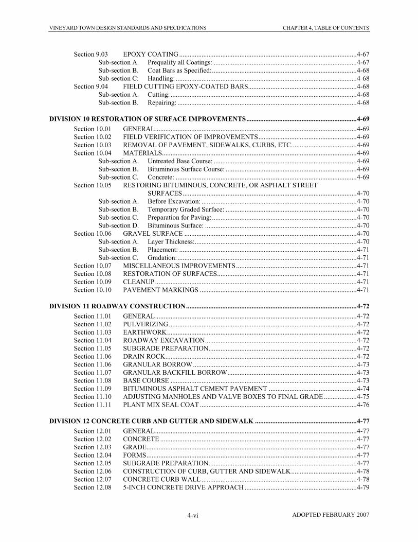
Section 9.03 EPOXY COATING.......................................................................................................4-67 Sub-section A. Prequalify all Coatings: ...................................................................................4-67 Sub-section B. Coat Bars as Specified:....................................................................................4-68 Sub-section C: Handling: .........................................................................................................4-68
Section 9.04 FIELD CUTTING EPOXY-COATED BARS...............................................................4-68 Sub-section A. Cutting: ............................................................................................................4-68 Sub-section B. Repairing: ........................................................................................................4-68
DIVISION 10 RESTORATION OF SURFACE IMPROVEMENTS................................................................4-69
Section 10.01 GENERAL.....................................................................................................................4-69 Section 10.02 FIELD VERIFICATION OF IMPROVEMENTS.........................................................4-69 Section 10.03 REMOVAL OF PAVEMENT, SIDEWALKS, CURBS, ETC......................................4-69 Section 10.04 MATERIALS.................................................................................................................4-69
Sub-section A. Untreated Base Course: ...................................................................................4-69 Sub-section B. Bituminous Surface Course: ............................................................................4-69 Sub-section C. Concrete: .........................................................................................................4-69
Section 10.05 RESTORING BITUMINOUS, CONCRETE, OR ASPHALT STREET
SURFACES.....................................................................................................4-70 Sub-section A. Before Excavation: ..........................................................................................4-70 Sub-section B. Temporary Graded Surface: ............................................................................4-70 Sub-section C. Preparation for Paving:....................................................................................4-70 Sub-section D. Bituminous Surface: ........................................................................................4-70
Section 10.06 GRAVEL SURFACE ....................................................................................................4-70 Sub-section A. Layer Thickness:..............................................................................................4-70 Sub-section B. Placement: .......................................................................................................4-71 Sub-section C. Gradation:........................................................................................................4-71
Section 10.07 MISCELLANEOUS IMPROVEMENTS......................................................................4-71 Section 10.08 RESTORATION OF SURFACES.................................................................................4-71 Section 10.09 CLEANUP.....................................................................................................................4-71 Section 10.10 PAVEMENT MARKINGS ...........................................................................................4-71
DIVISION 11 ROADWAY CONSTRUCTION...................................................................................................4-72
Section 11.01 GENERAL.....................................................................................................................4-72 Section 11.02 PULVERIZING.............................................................................................................4-72 Section 11.03 EARTHWORK..............................................................................................................4-72 Section 11.04 ROADWAY EXCAVATION........................................................................................4-72 Section 11.05 SUBGRADE PREPARATION......................................................................................4-72
Section 11.06 DRAIN ROCK...............................................................................................................4-72
Section 11.06 GRANULAR BORROW...............................................................................................4-73 Section 11.07 GRANULAR BACKFILL BORROW...........................................................................4-73 Section 11.08 BASE COURSE ............................................................................................................4-73 Section 11.09 BITUMINOUS ASPHALT CEMENT PAVEMENT ...................................................4-74 Section 11.10 ADJUSTING MANHOLES AND VALVE BOXES TO FINAL GRADE ...................4-75 Section 11.11 PLANT MIX SEAL COAT ...........................................................................................4-76
DIVISION 12 CONCRETE CURB AND GUTTER AND SIDEWALK ...........................................................4-77
Section 12.01 GENERAL.....................................................................................................................4-77 Section 12.02 CONCRETE ..................................................................................................................4-77 Section 12.03 GRADE..........................................................................................................................4-77 Section 12.04 FORMS..........................................................................................................................4-77 Section 12.05 SUBGRADE PREPARATION......................................................................................4-77 Section 12.06 CONSTRUCTION OF CURB, GUTTER AND SIDEWALK......................................4-78 Section 12.07 CONCRETE CURB WALL ..........................................................................................4-78 Section 12.08 5-INCH CONCRETE DRIVE APPROACH .................................................................4-79

VINEYARD TOWN DESIGN STANDARDS AND SPECIFICATIONS CHAPTER 4, TABLE OF CONTENTS
ADOPTED FEBRUARY 2007 4-vii
Section 12.09 ACCESSIBILITY STANDARDS IN PUBLIC RIGHTS-OF-WAY.............................4-79 Sub-section A. Sidewalks:........................................................................................................4-79 Sub-section B. Curb Ramps: ....................................................................................................4-79
Sub-section C. Landings: .........................................................................................................4-80
Sub-section D. Side Flares: ......................................................................................................4-80 Sub-section E. Detectible Warnings: .......................................................................................4-80 Sub-section F. Pedestrian Crossings:.......................................................................................4-81
Section 12.10 LANDSCAPE RESTORATION ...................................................................................4-81
DIVISION 13 STORM DRAINS...........................................................................................................................4-82
Section 13.01 GENERAL.....................................................................................................................4-82 Section 13.02 PIPE INSTALLATION .................................................................................................4-82 Section 13.03 PIPE...............................................................................................................................4-82 Section 13.05 CONCRETE ..................................................................................................................4-82 Section 13.06 REINFORCING STEEL................................................................................................4-82 Section 13.07 STORM DRAIN INLET BOXES .................................................................................4-82 Section 13.08 PIPE CONNECTING INLET BOXES TO EXISTING STORM DRAINS..................4-82
DIVISION 14 UTAH DEPARTMENT OF TRANSPORTATION RIGHTS-OF-WAY..................................4-83
Section 14.01 GENERAL.....................................................................................................................4-83 Section 14.02 UTILITY LINE AGREEMENT....................................................................................4-83 Section 14.03 INSPECTION FEES......................................................................................................4-83
DIVISION 15 CASINGS........................................................................................................................................4-84
Section 15.01 GENERAL.....................................................................................................................4-84 Section 15.02 MATERIALS.................................................................................................................4-84 Section 15.03 CONSTRUCTION METHODS ....................................................................................4-84 Section 15.04 LINE AND GRADE......................................................................................................4-84 Section 15.05 CARRIER PIPE INSTALLATION THROUGH CASINGS.........................................4-84
Section 15.06 CASING SPACERS ......................................................................................................4-84
DIVISION 16 FLOWABLE FILL ........................................................................................................................4-86
Section 16.01 GENERAL.....................................................................................................................4-86 Section 16.02 MIX DESIGN................................................................................................................4-86 Section 16.03 CONSTRUCTION METHODS ....................................................................................4-86 Section 16.04 CONSTRUCTION IN UDOT RIGHTS OF WAY .......................................................4-86
DIVISION 17 CONDUIT.......................................................................................................................................4-87
Section 17.01 GENERAL.....................................................................................................................4-87 Section 17.02 UTILITY CONDUIT.....................................................................................................4-87
Sub-section A. Materials:.........................................................................................................4-87 Sub-section B. Location:..........................................................................................................4-87 Sub-section C. Caution tape:....................................................................................................4-87
Section 17.03 TELECOMMUNICATIONS CONDUIT......................................................................4-87 Sub-section A. Telecommunication Conduit in New Developments: ......................................4-87 Sub-section B. Telecommunication Conduit for Future Use: ..................................................4-87 Sub-section C. Joints & Fittings: .............................................................................................4-88 Sub-section D. Caution tape:....................................................................................................4-88
Sub-section E. Tracer Wire: ....................................................................................................4-88
Section 17.04 INSTALLATION ..........................................................................................................4-88 Sub-section A. Cutting: ............................................................................................................4-88 Sub-section B. Dewatering of Trench:.....................................................................................4-88 Sub-section C. Laying of Conduit:...........................................................................................4-88

VINEYARD TOWN DESIGN STANDARDS AND SPECIFICATIONS CHAPTER 4, TABLE OF CONTENTS
ADOPTED FEBRUARY 2007 4-viii
Sub-section D. Bedding: ..........................................................................................................4-89
DIVISION 18 STREET LIGHTING....................................................................................................................4-90
Section 18.01 GENERAL.....................................................................................................................4-90 Section 18.02 MATERIALS.................................................................................................................4-90 Section 18.03 SPACING ......................................................................................................................4-90

VINEYARD TOWN DESIGN STANDARDS AND SPECIFICATIONS CHAPTER 4, DIVISION 1
ADOPTED FEBRUARY 2007 4-1
DIVISION 1
GENERAL REQUIREMENTS Section 1.01 PURPOSE OF DOCUMENTS The purpose of these Standard Specifications and Standard Drawings is to govern any work done or improvements installed within Public right-of-ways or across easements. Construction work shall comply with Vineyard Town Code, Title 17 Planning and Zoning. Owners/Contractors should thoroughly read and understand these specifications and standards before constructing public improvements. The Owner/Contractor shall contact the Vineyard Town Staff at the Vineyard Town Office, 240 East Gammon Rd, Vineyard, Utah 84058 for all matters dealing with construction work within a Town right-of-way or with any work connecting onto a Town utility. SPECIAL PERMITS AND BONDING ARE REQUIRED FOR ALL SUCH WORK. Section 1.02 PERMIT, FEES AND BONDING REQUIRED It shall be unlawful to do any construction, excavation work on any street, curb, gutter, sidewalk, sewer line, water line, pressure irrigation line, storm drain or other infrastructure addition or improvement in the Town of Vineyard without a Land Disturbance Permit from the Town to do so. The Town of Vineyard and all utility companies are bound by these standard specifications. No work shall be started until a permit is secured. In order to obtain a Land Disturbance Permit, the Owner’s/Contractor’s authorized signature is required. If a contract to do such work for the Town has been finalized, the contract fulfills the permit requirement. Sub-Section A. Permit Application:
All Land Disturbance Permit applications shall comply with Chapter 2 PUBLIC IMPROVEMENTS
PROCEDURES Section 1.02 LAND DISTURBANCE PERMIT.
Sub-Section B. Fee Assessment:
Before a permit is issued, a permit fee and an inspection fee shall be paid to Vineyard. These fees will be set by Council resolution. Fees shall be assessed on the following items:
1) Sewer and Water Lateral Installation Inspection 2) Re-inspection (When an inspection has been requested, the inspection is performed and the work is not
complete, a re-inspection fee shall be assessed.) 3) Barricades (provided by, or called out by the Town) 4) Bond
All public improvement projects done for Vineyard shall be bonded. Each contractor doing work in the Town is required to maintain a $2,000.00 bond with the Town. Bond requirements are to guarantee the following:
a) Construction work is completed. b) Final inspection is conducted. c) Repairs and/or replacement of required public improvements are finished and accepted.
The bonds shall be in the form of an irrevocable letter of credit from a bank, a bond from a surety company, or a cash bond paid directly to the Town. The Town shall approve all bonds submitted. No bond shall be released until all improvements are completed and accepted by the Town. Section 1.03 CONTRACTOR AND CONSTRUCTION PLAN APPROVAL Before a Contractor performs any work within the Town, the Town shall approve the Contractor. Approval is granted for a period of one (1) year upon submission of the following:
a) A current Utah State Contractor’s License. Work will be restricted to that authorized by the license.
b) Proof of comprehensive general liability insurance. Bodily injury insurance will be in an amount of not less than three hundred thousand dollars ($300,000.00) for any one occurrence. Property damage insurance will be in an amount of not less than two hundred thousand dollars ($200,000.00) for any one occurrence and

VINEYARD TOWN DESIGN STANDARDS AND SPECIFICATIONS CHAPTER 4, DIVISION 1
ADOPTED FEBRUARY 2007 4-2
shall include underground exposure. Combined liability insurance will be in an amount of not less than five hundred thousand dollars ($500,000.00) for any one occurrence.
c) A two thousand dollar ($2,000.00) performance bond owing to the Town, that will be in effect for a period
of one (1) year or one (1) year after the completion of work performed by the contractor, whichever is greater.
The Vineyard Engineer shall approve construction plans and cut sheets before any work begins. Owners/Contractors proceeding with work without such approvals shall have the project shut down until such approvals are obtained. Repeated offenses may result in the Contractor loosing its pre-qualification to perform work in the Town.
Section 1.04 PRE-CONSTRUCTION CONFERENCE A pre-construction meeting with the Owner and the Contractor(s) involved in the subdivision construction shall be held with the Public Works Representative/Engineer prior to commencement of any work. The location of the meeting shall be at the Vineyard Town Public Works Office, 240 East Gammon Rd, Vineyard, Utah 84058. The following items shall be furnished at the meeting:
a) A detailed outline showing the sequences of construction of principle items of work. The outline shall show
the beginning and ending dates of the major items of work on the Project.
b) A list of names, titles, addresses, and telephone numbers of the Owner/Contractor's responsible personnel,
indicating those who may be reached outside normal working hours.
c) A list of Sub-Contractors and Materials Suppliers to be involved with the project and the items of work they
are going to perform or furnish materials for. The Town will notify the Owner/Contractor of any concerns
or pre-qualification deficiencies of the companies they plan to use.
Other items may be discussed at this pre-construction conference as determined by the Vineyard Engineer. Official
minutes of this meeting as prepared by the Vineyard Engineer shall become part of the project file for the project. Section 1.05 TIMELY COMPLIANCE WITH THE ISSUED PERMIT The Owner/Contractor shall perform in accordance with the terms of the permit and the Standard Specifications and Standard Drawings in effect at the date of the permit. The work shall be done in a timely manner. Time limits may be a condition of the permit and may be shortened because of safety concerns. Permits may be suspended if compliance is not met.
Sub-section A. Inspections:
The Vineyard Town Engineer or his representative shall inspect work covered by a Land Disturbance Permit prior to the following:
1) Backfilling and compacting. 2) Placing concrete and asphalt 3) Placing any underground piping 4) Making any connection into a Town utility line 5) Other work done in a public right of way.
Vineyard Town Engineer shall also be notified prior to starting any project which meet the requirements established by the Land Disturbance Permit.

VINEYARD TOWN DESIGN STANDARDS AND SPECIFICATIONS CHAPTER 4, DIVISION 1
ADOPTED FEBRUARY 2007 4-3
Sub-section B. Notification of Needed Inspections:
1) Inspection performed during regular working hours requires at least twenty-four (24) hours’ notification.
2) Inspections needed after 4:00 p.m., require notification be given by 1:00 p.m. on the day of the inspection.
3) Inspections needed on the weekend, require that notification be given by 1:00 p.m. on the preceding Friday.
4) A charge shall be assessed for inspection call backs.
Sub-section C. Responsibility of the Owner: The Owner/contractor is responsible for the complete project, including construction, control of storm water and maintenance of infrastructure of the entire project, until it is finalized and accepted by the Town.
Sub-section D. Definition of “Town Engineer or representative”: The term “Town Engineer or representative” as used in these specifications refers to the Public Works Director, Public Works Inspector, Town Engineer, Public Works staff and others as designated by the Town Engineer. Sub-section E. Conflict: These Standard Specifications and Standard Drawings are the minimum requirements of the Town of Vineyard. In the event that any provisions herein conflict with general industrial standards, or with other requirements specified by the Town, the more stringent of the standards will apply.
Section 1.06 ELECTRONIC AND RECORD DRAWINGS
When the Owner’s Engineer has the capability, plat and improvement drawings shall be furnished electronically in
MicroStation Format (.dgn), AutoCAD format (.dwg) or Data Exchange Format (.dxf). These electronic files shall
be provided to the Town after completion of all of the improvements and final acceptance of the work by the Town.
A final bond release shall not be made to the Owner until these electronic files are received and reviewed by the
Town Engineer. The Owner shall be responsible for all costs associated with the preparation of these electronic
“Record Drawings.”
In addition to the electronic files, after completion of all public works improvements the Owner shall provide the
Town with two sets of velum or sepia (reproducible) “Record Drawings” which have been corrected to show the
constructed improvements. Final payment from the bond shall not be made until these records are received.
Section 1.07 TEMPORARY SERVICES
Any temporary services and utilities such as telephone, electrical, water toilet facilities, etc., shall be the
responsibility of the Owner/Contractor.
Section 1.08 CODES AND STANDARDS
Where codes and standards are referred to they shall be current, approved copies. It shall be the duty of the supplier
of any material on this work to submit evidence, if requested, that its material is in compliance with the applicable
codes and standards.
Section 1.09 STATE AND LOCAL LAWS
The Owner/Contractor shall conform to all applicable state and local laws in carrying out its obligations under the
Contract.
This shall include, but is not limited to, compliance by the Owner/Contractor with the requirements of Chapter 30, of
Title 34, of the Utah Code Annotated, 1953 as Amended. If the provisions of Section 34-30-1, of the Utah Code
Annotated, 1953 as amended, are not complied with, this Contract shall be void.

VINEYARD TOWN DESIGN STANDARDS AND SPECIFICATIONS CHAPTER 4, DIVISION 1
ADOPTED FEBRUARY 2007 4-4
Section 1.10 COMPLIANCE WITH GOVERNMENTAL REGULATIONS
The Owner/Contractor's personnel, equipment, and operations shall comply fully with all applicable standards,
regulations, and requirements of existing Federal, Utah State, and Local governmental agencies. This shall include,
but not necessarily be limited to, the following:
Sub-section A. United States Occupational Safety and Health Administration Regulations:
Title 29 of the Code of Federal Regulations, Part 1926 (29 CFR Part 1926), Safety and Health Regulations
for Construction.
Sub-section B. Utah State Industrial Commission Regulations:
The Utah Occupational Safety and Health Act (1973) and Employer-Employee Safe Practices for
Excavations and Trenching Operations (Jan. 1, 1974), as published by the Utah State Industrial
Commission, including any and all amendments or revisions effective prior to performance of the work.
Sub-section C. Town Ordinances:
The Owner/Contractor shall be required to comply with all Vineyard Town Ordinances.
Sub-section D. UDOT Requirements:
When crossing or working within Utah Department of Transportation rights-of-way the Owner/Contractor
shall be responsible to obtain all necessary permits and comply with all appropriate UDOT regulations
including applicable sections in "State of Utah Standard Specifications for Road and Bridge Construction,"
latest edition.
Sub-section E. Permits:
The Owner/Contractor is responsible to obtain all required business licenses and building permits
applicable to this project. Owner/Contractor shall be subject to the conditions of all permits and agreements
between the Owner and the permitting agencies. See Division 14, Rights-of-Way.
Section 1.11 FEDERAL, STATE, AND LOCAL INSPECTING AGENCIES
The site of construction is to be open at all reasonable times and places for periodic observation by accredited
representatives of the Federal, State, and local agencies who have regulatory or supervisory authority over any part
of the work proposed or regulated thereto.
Section 1.12 PUBLIC SAFETY AND CONVENIENCE
The convenience of the general public and the protection of persons and property is of prime importance and shall be
provided for by the Owner/Contractor during this project. The Owner/Contractor shall use every reasonable
precaution to safeguard persons and property. Failure of the Owner or the Public Works Representative/Engineer to
notify the Owner/Contractor of any deficiencies in providing for public safety and convenience shall not relieve the
Owner/Contractor from its responsibility. The Owner/Contractor shall be required to comply with the requirements
of the Manual on Uniform Traffic Control Devices (MUTCD).

VINEYARD TOWN DESIGN STANDARDS AND SPECIFICATIONS CHAPTER 4, DIVISION 1
ADOPTED FEBRUARY 2007 4-5
Sub-section A. Compliance with Rules and Regulations:
The Owner/Contractor shall comply with all rules and regulations of the Town, County, and State
authorities regarding the closing of public streets, or highways, to the use of public traffic. If conditions
justify, the Public Works Representative/Engineer may authorize the Owner/Contractor to close general
traffic to not more than one (1) Town block at any given time. No such closure shall be made without
authorization of the Public Works Representative/Engineer. Closure of streets or highways shall be in
conformance with the (MUTCD).
Sub-section B. Road Closures and Obstructions:
No road shall be closed by the Owner/Contractor to the public except by express permission of the Public
Works Representative/Engineer. The Owner/Contractor shall, at all times, conduct its work so as to insure
the least possible obstruction to traffic and normal commercial pursuits.
Sub-section C. Protection of the Traveling Public:
All obstructions within traveled roadways shall be protected by signs, barricades, and lights where
necessary for the safety of the traveling public. All barricades and obstructions shall be protected at night by
signal lights that shall be suitably distributed across the roadway and kept burning from sunset to sunrise.
Barricades shall be of substantial construction. Failure of the Owner or the Public Works
Representative/Engineer to notify the Owner/Contractor to maintain barricades, barriers, lights, flares,
danger signals, or guards shall not relieve the Owner/Contractor from its responsibility.
Sub-section D. Hazardous Conditions:
Whenever the Owner/Contractor's operations create a hazardous condition, it shall furnish flaggers and
guards to give adequate warning to the public of any dangerous conditions to be encountered. It shall
furnish, erect, and maintain fences, barricades, signs, lights, and other devices that may be necessary to
prevent injury and damage to persons and property. Flaggers and guards shall be UDOT trained and shall
hold current certification and shall be equipped with signs, flags, etc. as required by the Utah State
Department of Transportation (UDOT) regulations.
Sub-section E. Dust and Debris Control:
The Owner/Contractor shall control dust and debris that originates in the construction right-of-way or site.
Dust, trash, and other debris shall be controlled on a daily basis by methods that shall include, but not be
limited to, the use of a dust setting spray, a “pick-up broom or street sweeper and trash disposal. The
Owner/Contractor shall maintain on the project site a water truck with a minimum two thousand (2,000)
gallon capacity. The Owner/Contractor shall be responsible to secure a source of water and shall obtain the
necessary permission for its use. Failure by the Owner/Contractor to adequately control dust and debris
may result in the Owner initiating dust and debris control measures and deducting the cost from payment
due to the Owner/Contractor.
Section 1.13 CONFINEMENT OF WORK AND ACCESS TO RIGHT-OF-WAY AND EASEMENTS
The Owner/Contractor will be required to confine construction operations within the dedicated right-of-way for
public thoroughfares or within areas for which construction easements have been obtained unless it has made special
arrangements with the affected property owners in advance. The Owner/Contractor will be required to protect stored
materials, lawn, trees, and other features located adjacent to the proposed construction site. During construction
operations, the Owner/Contractor shall construct and maintain such facilities as may be required to provide access by
all property owners to their property. No person shall be cut off from access to their residences or places of business
for a period exceeding eight (8) hours, unless the Owner/Contractor has made special arrangements with the affected
persons prior to commencing work in the area.

VINEYARD TOWN DESIGN STANDARDS AND SPECIFICATIONS CHAPTER 4, DIVISION 1
ADOPTED FEBRUARY 2007 4-6
Section 1.14 NOTIFICATION OF RESIDENTS
All property owners and residents adjacent to the streets or easements affected by the construction shall be notified
by the Owner/Contractor at least forty-eight (48) hours in advance of time construction begins. The
Owner/Contractor can satisfy this requirement by placing a written notice on the door of each residence or business
reading "Notice of Construction Operation. (Owner/Contractor) will be working on the construction of street
improvements on your street starting about ." The Owner/Contractor shall provide a copy of the
notification form at the pre-construction meeting and the method to be used (hang on door, etc.)
Section 1.15 WEATHER CONDITIONS
In the event of temporary suspension of work, or during inclement weather, the Owner/Contractor will, and will
cause its Contractors/Subcontractors to, protect any project work or materials against damage from the weather. If, in
the opinion of the Public Works Representative/Engineer, any Project work or materials become damaged by reason
of failure on the part of the Owner/Contractor or any of its Contractors/Subcontractors to so protect its work, such
work or materials shall be removed and replaced at the expense of the Owner/Contractor.
Section 1.16 LAND MONUMENTS
The Owner/Contractor shall preserve existing Town, County, State, and Federal land monuments whenever possible.
When these monuments cannot be preserved, the Owner/Contractor shall notify the Public Works
Representative/Engineer at least two (2) weeks in advance of the proposed construction in order that the Public
Works Representative/Engineer will have ample opportunity to reference these monuments for later replacement.
Section 1.17 SOURCE OF MATERIALS
All materials furnished or incorporated in this project shall conform to the requirements of these Specifications.
The Owner/Contractor shall acquire the necessary rights, at its own expense, to take material from aggregate sources
and to use properties for plant site, hauling roads, and other purposes.
The Owner/Contractor may select areas for disposal of surplus materials; however, the Owner/Contractor will be
responsible for acquiring the necessary right, at its own expense, to use the property for such purpose.
Section 1.18 OPERATION AND MAINTENANCE MANUALS
The Owner/Contractor shall furnish the Public Works Representative/Engineer with two (2) sets of all operation and
maintenance manuals, drawings, diagrams, etc., for all pumps, motors, control panels, valves, meters, etc., for use in
the Operation and Maintenance Manual.
Section 1.19 INTERFERING STRUCTURES, UTILITIES AND FACILITIES
The Owner/Contractor shall exercise all possible caution to prevent damage to existing structures and utilities,
whether above ground or underground. While these structures and utilities may be shown on the improvements plans,
the information has been compiled from the best available sources, its completeness and accuracy cannot be
guaranteed, and it is presented simply as a guide to possible difficulties. The Owner/Contractor shall notify all utility
offices concerned at least forty-eight (48) hours in advance of construction operations in which a utility agency's
facility may be involved. Notification to blue stakes does not necessarily cover all buried lines. This shall include,
but not be limited to, irrigation, water, telephone, electric, sewer, storm drain, gas, and cable television. The
Owner/Contractor shall be responsible for any and all changes to, relocation of, or re-connection to public utility
facilities encountered or interrupted during the prosecution of the work, and all costs relating thereto shall be at the
Owner/Contractor's expense. The Owner/Contractor shall contract with and pay Public Utility Agencies for work
required in connection with all utility interference’s and handle all necessary notifications, scheduling, coordination
and details.

VINEYARD TOWN DESIGN STANDARDS AND SPECIFICATIONS CHAPTER 4, DIVISION 1
ADOPTED FEBRUARY 2007 4-7
It shall be the responsibility of the Owner/Contractor to relocate and expose all existing underground structures and
utilities in such a manner as to prevent damage to the same. Any structure or utilities damaged by the Work shall be
repaired or replaced at the Owner/Contractor's expense.
If the Owner/Contractor encounters existing structures that will prevent construction, it shall notify the Public Works
Representative/Engineer before continuing with the construction in order that the Owner’s Engineer or Public Works
Representative/Engineer may make such field revisions as necessary to avoid conflict with the existing structures.
Section 1.20 MATERIAL AND COMPACTION TESTING
The Owner/Contractor has the responsibility to adequately test native materials and construction materials, and to
furnish the Town with manufacturer’s certifications of material quality.
Sub-section A. Quality Assurance:
The Owner/Contractor shall be responsible for all sampling, delivery of samples to a qualified testing
agency, testing, and delivery of test results or materials certifications to Town at no charge to the Town.
Testing and certifications reports shall be approved by the Town as to conformance to Town standard
specifications prior to final inspection and/or acceptance by the Town of any materials or workmanship.
Sub-section B. Submittals:
Submittals shall consist of two types:
1) Field Test Report: When possible submit original report immediately to Public Works
Representative/Engineer, but in no case later than end of following day.
2) Laboratory Test Report: Submit original report to Public Works Representative/Engineer within 48
hours after test results are determined. Sub-section C. Sampling:
1) Sampling of materials shall be as specified in each test.
2) The Public Works Representative/Engineer may require that sampling be performed in their presence,
in which case the Owner of Contractor shall be notified of this requirement in writing at the time the
building permit is issued, or at the Preconstruction meeting, or when construction drawings are released
by the Town for construction, as applicable.
3) The presence of a Public Works Representative/Engineer shall not relieve the Owner/Contractor of any
requirements in this Section.
4) Each sample or test shall be accompanied by the following written data, which shall be reported to the
Town with test results:
a) Name of Project
b) Name of Owner/Contractor
c) Project Street Address
d) Appropriate Test Name
e) Date of Sampling
f) Sample Number (if more than one sample per day)
g) Name of technician who performed the testing
h) Location of sample
Sub-section D. Soil Classification Test:
1) The soil classification test shall be conducted to determine the suitability of native soils for road sub-
grade and building foundations.
2) The soil shall be classified according to the Unified Soil Classification System and/or AASHTO soil
classifications
3) The AASHTO soil classification test shall conform to AASHTO M-145 of latest revision

VINEYARD TOWN DESIGN STANDARDS AND SPECIFICATIONS CHAPTER 4, DIVISION 1
ADOPTED FEBRUARY 2007 4-8
4) One soil classification test shall be required for each test area. A test area shall be limited to one parcel
of one soil type, a maximum 1,000 feet long and maximum 5 acres. The Public Works
Representative/Engineer may modify this requirement on a case by case basis.
5) The soil sample shall be taken from a test area at a minimum depth of 24-inches below the future
design grades, of native soil, and shall be free from foreign material, asphalt, concrete, ice or manmade
materials.
6) Where deep footings or pile foundations are proposed, soil classification tests at several depths may be
required in each test area.
7) The results of all determinations shall be reported to the Town in the form of a Geotechnical Report.
The geotechnical report shall be certified by a Licensed Professional Engineer qualified in these types
of investigations. The geotechnical report shall include, with additions as deemed necessary by the
Public Works Representative/Engineer, the following information:
a) A plot plan showing the location of all test borings and excavations.
b) Descriptions and classifications of the materials encountered.
c) Elevations of the water table, if encountered and an opinion of the seasonal fluctuation of the level.
d) Evaluation of the subsurface soil conditions at the site.
e) Assess the appropriate engineering characteristics of the subsurface soils.
f) Provide geotechnical recommendations for general site grading, the design and construction of
foundations, basements, concrete floor slabs, and asphalt pavement sections. The report shall
include soil strength, bearing capacity, and provisions to mitigate the effects of expansive soils,
collapsible soils, liquefaction, and adjacent loads.
g) Expected total and differential settlement.
Sub-section E. Compaction Test of Soil and Untreated Base Course:
1) Laboratory test to establish maximum laboratory density shall be determined in accordance with
AASHTO T-180, Method D or ASTM D 1557.
2) Samples to determine laboratory density shall be taken from the stockpiled backfill or from the un-
compacted base course in place.
3) The acceptance of soil and base course with respect to compaction shall be based upon the average
density of all density tests made in a lot.
a) Field density tests shall be taken as specified in AASHTO T-191 or by use of a portable nuclear
density testing device. Field density tests shall be taken at a depth equal to ½ the maximum depth
of the lift tested.
b) A lot shall equal the amount of soil or untreated base course compacted in each production day.
c) A test lot shall be divided into sub-lots and one density test shall be taken within each sub-lot.
d) The location of sampling sites within the sub-lot shall be chosen on a random basis by use of a
suitable random number table or at the locations designated by the Public Works
Representative/Engineer.
e) Each test lot shall have a minimum of two (2) sub-lots. A sub-lot shall be no larger than 1,000
cubic yards for embankment, no larger than 200 cubic yards for backfill over pipe or against
structures and no larger than 500 tons for untreated road base.
4) The test results of all samples tested shall be reported to the Town. A test lot shall be accepted when
the average of the density determinations is not less than the density required for that improvement in
theses specifications and when no one density determination is less than 95% of the density required by
theses specifications.
5) Compaction test not meeting the required specifications may be rejected and re-compaction or related
construction efforts to obtain compaction shall be at the Owner/Contractor’s expense
Sub-section F. Test Roll of Roadway Sub-grade:
1) Roll Test shall be performed when required by the Public Works Representative/Engineer to determine
the structural integrity of the sub-grade and street section.
2) The Roll Test shall be performed as follows:
a) The Owner/Contractor shall provide a loaded 10 wheel dump truck or water truck to drive over the
sub-grade material within the roadway.

VINEYARD TOWN DESIGN STANDARDS AND SPECIFICATIONS CHAPTER 4, DIVISION 1
ADOPTED FEBRUARY 2007 4-9
b) The loaded truck shall be driven slowly over the sub-grade to locate soft spots in the sub-grade
surface.
c) Soft spots in the sub-grade shall be identified and marked by the Public Works
Representative/Engineer.
d) It shall be the Owner/Contractor’s responsibility to remove the rejected sub-grade material to depth
determined by Public Works Representative/Engineer. The rejected material shall be replaced with
A-1 granular backfill material approved by Public Works Representative/Engineer.
Sub-section G. Gradation Test of Untreated Base Course:
1) The gradation of untreated base course shall be determined in accordance with AASHTO T-27
2) The total amount of material passing the No. 200 sieve shall be determined by washing in water in
accordance with AASHTO T-11.
3) The acceptance of road base with respect to gradation shall be based upon the average of all
determinations in a lot. A lot shall be limited to one source of borrow and limited to one subdivision
plat or one development. One sample shall be required for each 500 tons or any fraction thereof of
untreated base course in a test lot. When the test lot is less than 100 tons, the requirement for the
gradation test may be waived by the Public Works Representative/Engineer.
4) The location of sampling sites within the sub-lot shall be chosen on a random basis by use of a suitable
random number table or at the locations designated by the Public Works Representative/Engineer.
5) All material not conforming to the specified gradations may be rejected and replaced with material
conforming to the specified gradations at the Owner/Contractor’s expense.
Sub-section H. Extraction – Gradation Testing of Bituminous Surface Course:
1) Samples of the bituminous surface course or asphalt concrete shall be tested with respect to gradation
and bitumen content in accordance with Utah Department of Highways Test Procedure 8-946 and 8-
947 if required by the Public Works Representative/Engineer.
2) Mix design shall be submitted to the Public Works Representative/Engineer for approval 5 working
days before work is to begin.
3) Acceptance of bituminous surface course with respect to gradation and bitumen content shall be base
upon the average of the determinations made in a lot.
a) A lot shall equal the amount of bituminous surface course placed in each production day.
b) When a lot exceeds 500 tons, a minimum of three (3) samples shall be taken in each lot.
c) When a lot is 500 tons or less, a minimum of two (2) samples shall be taken.
d) Samples shall be taken at the time of lay-down of bituminous surface course and before
compaction. Samples shall be taken from the mat behind the lay-down machine.
e) Sampling shall be timed to represent the entire production day. The time of day, date or sample,
station and offset location shall be clearly marked with the sample.
f) If the average asphalt is less than 2.5% of optimal content, the Contractor may be required to lay
an additional lift, based on the Public Works Representative/Engineer recommendation.
Sub-section I. Compaction Testing of Bituminous Surface Course:
1) Laboratory tests to establish the maximum laboratory density of bituminous surface course shall be
determined by the “Marshall Test” in accordance to ASHTM D-1559.
2) Samples to determine maximum laboratory density shall be taken at the time bituminous surface course
is placed and before compaction.
3) Acceptance of bituminous surface course with respect to compaction shall be based upon the average
determination of field density tests made in a lot.
a) Field density test shall be by laboratory density analysis of core samples.
b) A test lot shall be the quantity of surface course placed and compacted in each construction day.
c) The test lot shall be subdivided into sub-lot(s) of approximately equal size and no larger than 2,000
square yards in area.

VINEYARD TOWN DESIGN STANDARDS AND SPECIFICATIONS CHAPTER 4, DIVISION 1
ADOPTED FEBRUARY 2007 4-10
d) The location of sampling sites within the sub-lot shall be chosen on a random basis by use of a
suitable random number table or at the locations designated by the Public Works
Representative/Engineer.
4) The test lot shall be accepted with respect to density when the average of all density determinations is
not less than the density required by Division 11 Section 11.09.
5) Core Tests.
a) Acceptance of the completed bituminous surface course with respect to thickness shall be based on
the average thickness of a test lot.
1) A test lot shall equal approximately 4,000 square yards of completed roadway.
2) A lot shall be divided into sub-lots of approximately 2,000 square yards.
b) One thickness test, randomly selected by use of a random number table or at the locations
designated by the Public Works Representative/Engineer, shall be taken within each sub-lot. A
minimum of three core tests will be taken.
c) A lot shall be accepted when the average thickness of all sub-lots is less than 3/8-inch less than the
total designated bituminous surface course thickness and when no individual sub-lot shows a
deficient thickness of more than 1/2-inch.
d) Lots or sub-lots that are not acceptable because of deficient thickness shall be brought into
compliance by placing additional surface course as directed by the Public Works
Representative/Engineer.
e) The removed core will be replaced with hot asphalt or low strength concrete.
Sub-section J. Compressive Strength Testing of Concrete Cylinders:
1) Samples of concrete shall be taken at the construction site, molded in standard cylinder shapes, allowed
to cure, and tested with respect to comprehensive strength.
2) All samples of concrete shall be taken in conformance to AASHTO T-141, latest revision.
3) Acceptance of concrete with respect to compressive strength shall be based upon the average
determination of all “compressive strength tests” made in a lot.
a) A test lot shall be the quantity of concrete placed at one job in a construction day.
b) A minimum of one “compressive strength test” will be taken of three cylinders for each 50 cubic
yards concrete in a test lot, or fraction thereof. If placement is less than 5 cubic yards, proceed as
directed by the Public Works Representative/Engineer.
c) The making and curing concrete test specimens in the field shall conform to AASHTO T-23.
Compressive strength of cylindrical concrete specimens shall conform to AASHTO T-22.
4) Concrete may be rejected if desired strengths are not obtained. The concrete for which the tests failed
shall be removed and replaced at the Owner/Contractor’s expense.
Sub-section K. Additional Concrete Testing:
1) Slump Test: Determine slump in accordance with AASHTO T-27, (ASTM C-143). Use one test for
each 50 cubic yards or fraction thereof. Reject concrete failing slump test (see Division 8 Section 8.04,
Sub-section B).
2) Air Test: Determine normal weight concrete air content using AASHTO T-152 (ASTM C-231) for
each 50 cubic yards or fraction thereof. Light weight concrete air content use ASTM C-173.
a) If an air test fails, immediately retest the same load (do not mix or add water between tests).
b) The concrete will be rejected if the second air test does not meet the specification.
c) If the second air test meets the specification, a third test will be performed to establish concrete
acceptance or rejection.
3) When requested by Public Works Representative/Engineer, test in-place concrete by impact hammer,
sonoscope, or other nondestructive device.
a) To determine relative strengths in various locations in Work.
b) To aid in evaluating concrete strength.
c) To select areas to be cored.
Sub-section L. Certifications:

VINEYARD TOWN DESIGN STANDARDS AND SPECIFICATIONS CHAPTER 4, DIVISION 1
ADOPTED FEBRUARY 2007 4-11
1) When requested by the Public Works Representative/Engineer the Owner/Contractor shall obtain a
manufacture’s certificate certifying conformance to the applicable requirements of these Standard
Specifications. Certifications that may be requested are but are not limited to those listed below:
a) Valves: Gate, Butterfly, Specialty.
b) Reinforcing Steel.
c) Structural Steel.
d) Pipe: Ductile Iron, AWWA C 900 or 905 PVC, Polyvinyl Chloride (Gravity, SDR 35), Concrete,
Polyethylene Corrugated, Polyethylene (CTS), and Type K Copper.
e) Fire hydrants.
Sub-section M. Summary Table of Tests and Certifications:
1) The following is a summary of the tests, number of samples per test, and certificates that are or may be
required for construction work and developments in Pleasant Grove Town. This summary is provided
as a reference guide. For details governing each item, refer to the appropriate test specification herein.
Test Subject Specific Test Number of Tests
Soil Classification Unified Soil Classification System or
AASHTO M-145
1 test per test area of uniform soil
type and 5 acres maximum.
Compaction of Embankments,
Soil, Trench Backfill and Base
Course.
Embankments, Soil, and Base
Course field density.
Trench Backfill field density.
Lab Density - AASHTO T-180 Method
D or ASTM D-1557 as applicable.
Portable Nuclear Equipment or
AASHTO T-191 (ASTM D-2922-96)
Portable Nuclear Equipment or
AASHTO T-191 (ASTM D-2922-96)
As needed to establish laboratory
density.
1 test per sub-lot plus minimum one
test per 1,000 cu. Yards.
1 test per sub-lot plus minimum one
test per 100 feet of trench.
Test Roll of Roadway Sub-grade N/A As required by Public Works
Representative/Engineer.
Base Course Gradation Sieve Analysis – AASHTO T-27
Passing No. 200 Sieve – AASHTO T-
11
1 test per 500 tons.
Extraction-Gradation Test of
Bituminous Surface Course
UDOT Test Procedure 8-946 & 8-947 If lot is > 500 tons, 3 tests per
pavement construction day if lot is <
500 tons, 2 tests per pavement
construction day.
Compaction of Bituminous
Surface Course
Lab Density-Marshall Test, ASTM D-
1559.
1 test per pavement construction
day.
1 test per sub-lot (2,000 square
yards).
Core Tests 4” Core Sample 1 test per pavement construction
day.
1 thickness test per 2,000 square
yards or 3 test minimum.
Concrete Test Cylinders AASHTO T-23 and AASHTO T-22 Minimum of one “compressive
strength test” of 3 cylinders for each

VINEYARD TOWN DESIGN STANDARDS AND SPECIFICATIONS CHAPTER 4, DIVISION 1
ADOPTED FEBRUARY 2007 4-12
Test Subject Specific Test Number of Tests
50 cubic yards in a test lot, or
fraction thereof.
Slump Test
Air Test
AASHTO T-27 (ASTM C-143)
AASHTO T-152 (ASTM C-231)
One test for each 50 cubic yards or
fraction thereof.
One test for each 50 cubic yards or
fraction thereof.
Specialty Valves (Pressure
Reducing, Regulating Valves, etc)
Manufacture’s Certificate 1 for each valve.
Gate Valve Manufacture’s Certificate 1 for each valve.
Butterfly Valves Manufacture’s Certificate 1 for each valve.
Reinforcing Steel Manufacture’s Certificate 1 for each 1,000 pounds of one
grade.
Structural Steel Manufacture’s Certificate 1 for each lot of one shape, one
grade.
Pipe: Ductile Iron, AWWA PVC,
Polyvinyl Chloride (SDR 25),
Concrete, Polyethylene
Corrugated
Manufacture’s Certificate 1 for each 500 lineal feet of one
size, one class.
Polyethylene (CTS) and Type K
Copper.
Manufacture’s Certificate 1 for each 500 lineal feet of one
size, one class
Section 1.21 TELEVISING SEWER MAINS
Prior to the Town accepting newly constructed sewers the Contractor/Owner must provide the Town with a videotape of
the televising of the sewer (performed in the presence of the Public Works Representative). The Contractor/Owner shall
pay the cost of televising the sewer. The televising equipment used must record on the videotape a continuous distance
from the point of beginning.

VINEYARD TOWN DESIGN STANDARDS AND SPECIFICATIONS CHAPTER 4, DIVISION 2
ADOPTED FEBRUARY 2007 4-13
DIVISION 2
TRENCH EXCAVATION AND BACKFILL
Section 2.01 GENERAL
This section covers the requirements for trenching and backfilling for underground pipelines. Unless otherwise
shown or ordered, pipe shall be laid in an open trench. All incidental clearing, preliminary grading, structure
removal, and benching shall be considered a part of the trenching operation.
Section 2.02 BARRICADES
Barriers shall be placed at each end of all excavations, and at such places as may be necessary along excavations, to
warn all pedestrians and vehicular traffic of such excavations. Lights shall also be placed along excavations from one
hour before sunset each day to one hour after sunrise of the next day, until such excavations are entirely refilled,
compacted, and surfaced or final graded. All excavations shall be barricaded in such a manner as to prevent persons
from walking into, falling into, or otherwise entering those excavations.
Section 2.03 BLASTING
Blasting will not be allowed except by permission from the Public Works Representative/Engineer. The
Owner/Contractor shall comply with all laws, regulations, ordinances, and safety codes relative to the handling,
storage, and use of explosives. The Owner/Contractor shall be fully responsible for all damage to life and property
attributable to its blasting operations. Excessive blasting or overshooting will not be permitted. The
Owner/Contractor shall remove any material outside the authorized cross section, which may be shattered or
loosened by blasting.
Section 2.04 SHEETING, BRACING AND SHORING OF EXCAVATIONS
Excavations shall be sheeted, braced, and shored as required to support the walls of the excavations. These measures
shall be taken to protect the workers, the work in progress, existing utilities, structures, and improvements, from
damage due to sliding and settling of trench walls. All such sheeting, bracing, and shoring shall comply with the
regulations of the Utah State Industrial Commission, and accident prevention and safety provisions of the Contract.
The Owner/Contractor shall be fully responsible for the adequacy of methods and materials used in trench sheeting,
bracing, shoring, and other systems provided to protect workers. Injury to or death of workers resulting from
inadequate trench safety measures shall be the full and complete responsibility of the Owner/Contractor. All
damages resulting from lack of adequate sheeting, bracing and shoring shall be the responsibility of the
Owner/Contractor, and the Owner/Contractor shall affect all necessary repairs or reconstruction at its own expense
resulting from such damage.
Sheeting or shoring that does not extend below the centerline of the pipe may be removed at the discretion and
responsibility of the Owner/Contractor after the pipe embedment has been placed and compacted to a level twelve
inches (12") above the top of the pipe. Following removal of the sheeting or bracing, the trench shall be immediately
backfilled and compacted or consolidated.

VINEYARD TOWN DESIGN STANDARDS AND SPECIFICATIONS CHAPTER 4, DIVISION 2
ADOPTED FEBRUARY 2007 4-14
Section 2.05 CONTROL OF GROUNDWATER
All trenches shall be kept free from water during excavation, fine grading, pipe laying and jointing, and pipe
embedment operations. Where the trench bottom is mucky or otherwise unstable because of the presence of
groundwater, and in all cases where the static groundwater is above the bottom of any trench or bell hole excavation,
such groundwater shall be lowered to the extent necessary to keep the trench free from water and the trench bottom
stable when the work within the trench is in progress. The discharge from excavation dewatering shall be conducted
to natural drainage channels, gutters, drains, or storm sewers. No sanitary sewer shall be used for disposal of trench
water. Surface water shall be prevented from entering trenches.
Section 2.06 TRENCH EXCAVATION
Excavation for pipelines shall be located as shown on the Drawings or as staked in the field. Trenches shall be
excavated to the depths and widths required to accommodate the construction of the pipelines, as follows:
Sub-section A. Normal Excavation:
Except in ledge-rock, cobbles, stones, or water-saturated earth, mechanical excavation of trenches shall not
extend below an elevation four inches (4”) above the bottom of the pipe after placement in its final position.
All additional excavation necessary for preparation of the trench bottom shall be made manually.
Sub-section B. Authorized Over-Excavation:
Where ledge-rock, cobble rock, stones or other material render the trench material unsuitable for pipe
bedding, as determined by the Public Works Representative/Engineer, bedding material shall be imported
and placed. The trench shall be excavated to a minimum of four-inches (4”) below the bottom of the pipe
after placement in its final position.
Where unstable material is encountered in the excavation, foundation material may be required, as
determined by the Public Works Representative/Engineer. In such cases, a minimum of eight inches (8")
below the bottom of the pipe after placement in its final position shall be removed. Over-excavation not
ordered, specified, or shown shall be considered to be unauthorized excavation.
Sub-section C. Unauthorized Over-Excavation:
Any excavation carried below the elevation required to install the pipe as specified in these Specifications,
or directed by the Public Works Representative/Engineer, shall be considered to be unauthorized. Such
excavation shall be backfilled in accordance with these Specifications for "Imported Granular Material" and
"Gravel Foundation for Pipelines and Pipeline Structures," all at the Owner/Contractor's expense.
Sub-section D. Trench Width:
The trench shall be excavated such that the pipe is always centered in the trench. The minimum clear trench
width at the horizontal diameter of the pipe must not be less than the outside diameter of the pipe plus
twelve inches (12"). The maximum clear width of trench at the top of the pipe must not be more than the
outside diameter of the pipe plus eighteen inches (18"). If a trench is excavated to a greater width, the
Owner/Contractor will be required to restore the trench to an acceptable condition by following the steps
outlined in these Specifications for "Trenches in Embankments."
Trench width for pipeline structures, valves, or other accessories shall be sufficient to leave at least twelve
inches (12") clear between their outer surfaces and the trench. Backfill with earth under structures or valves
will not be permitted. Any unauthorized excess excavation below the elevation indicated for foundation of
any structures shall be backfilled in accordance with these specifications for "Imported Granular Materials,"
and "Gravel Foundation for Pipe & Pipeline Structures," at the Owner/Contractor's expense.

VINEYARD TOWN DESIGN STANDARDS AND SPECIFICATIONS CHAPTER 4, DIVISION 2
ADOPTED FEBRUARY 2007 4-15
Sub-section E. Trenches in Embankments:
Before laying pipes that are to be in fill or embankment areas, the embankment shall first be placed and
compacted to the specified density to a depth of not less than two feet (2') above the top of the proposed
pipe. After placing and compacting the embankment, the trench for the pipe or conduit shall be excavated
through the fill and fine graded and the pipe installed as specified.
Sub-section F. Placement of Excavated Material:
All excess material shall be hauled away from the construction site and disposed of in an area obtained by
the Owner/Contractor and approved by the Public Works Representative/Engineer. The Owner/Contractor
shall be responsible for all rights-of-way, easements, and access associated with the disposal of excess
excavated material. It shall further be responsible to obtain permission from the property owner or person
controlling the property where the Owner/Contractor plans to dispose of excavated material. No
compensation will be made to the Owner/Contractor for disposal of excess excavated material.
Non-excess excavated material shall be piled in a manner that will not endanger the work and will avoid
obstructing sidewalks and driveways. Gutters and irrigation ditches shall be kept clear or other satisfactory
provisions shall be made for street drainage and continuity of irrigation.
Grading of the area surrounding the trenches, including excavated materials, shall be performed as
necessary to prevent surface water from flowing into trenches, or other excavations. Control of groundwater
shall be as specified in section 2.05, Control of Groundwater.
Sub-section G. Fine Grading the Trench Bottom:
The bottom of the trench shall be accurately graded and prepared to provide uniform bearing and support
on undisturbed soil or compacted granular bedding at every point along the entire length of the pipe. Bell
holes shall be hand excavated after the trench bottom has been fine graded. Bell holes shall be only large
enough to permit making the joints and to assure that any portion of the joint or bell does not support the
pipe.
Section 2.07 TRENCH BACKFILL
Trench backfill for piping consists of four zones: foundation, bedding, initial backfill, and final backfill. “Pipe
embedment” is a commonly used term that refers to the region including the bedding and initial backfill zones, or
any region within one foot (1’) of any pipe, pipeline structure, or accessory. The foundation is defined as the region
between eight inches (8”) and four inches (4”) below the bottom of the pipe. The bedding is defined as the region
between four inches (4”) below the bottom of the pipe and the bottom of the pipe. The initial backfill is defined as
the region between the bottom of the pipe and twelve inches (12”) above the top of the pipe. The final backfill is
defined as the region above twelve inches (12”) above the pipe.
All fill materials shall be compacted as specified in this section.
The Public Works Representative/Engineer shall determine the suitability of excavated materials for use as
foundation, bedding, initial backfill, and final backfill. When the excavated materials are not satisfactory for
foundation, bedding, or backfill, the Owner/Contractor shall provide imported granular material.
Sub-section A. Imported Granular Material:
Imported granular material for foundation, bedding, and backfill shall be cleaned crushed rock or gravel,
free from sod, vegetation, and other organic or deleterious material. Slag will not be allowed in the pipe
embedment. Imported granular material shall conform to the following gradation specifications:
1) Pipe Embedment Material:

VINEYARD TOWN DESIGN STANDARDS AND SPECIFICATIONS CHAPTER 4, DIVISION 2
ADOPTED FEBRUARY 2007 4-16
i. Foundation Material: One hundred percent (100%) less than two-inch (2”) and
maximum of five percent (5%) less than one-half-inch (1/2”).
ii. Bedding and Initial Backfill Material:
a. Ductile-iron pipe - One hundred percent (100%) less than two-inch (2”) and
maximum of five percent (5%) passing a No. 200 sieve.
b. PVC or polyethylene pipe - One hundred percent (100%) less than one-inch
(1”) and maximum five percent (5%) passing a No. 200 sieve.
c. Concrete pipe - Refer to Section 4.06 (Concrete Pipe / Pipe Bedding)
2) Final Backfill Material: One hundred percent (100%) less than three-inch (3”) and
maximum of fifteen percent (15%) passing a No. 200 sieve.
Sub-section B. Foundation Placement:
When over-excavation is authorized by the Public Works Representative/Engineer, foundation material
shall be placed in the foundation zone and below. The foundation material shall be placed so that the trench
can be properly fine graded as specified. The foundation material shall be deposited over the entire trench
width and compacted in layers. The layers shall have a maximum uncompacted thickness of six-inches (6”).
The material shall then be fine graded in accordance with the specification for Fine grading herein.
Sub-section C. Pipe Embedment:
Embedment material for other than PVC pipe may be excavated materials consisting of loose earth, sand, or
gravel having no material larger than two-inches (2”) in any dimension. For PVC pipe, the material must be
no greater than-one inch (1”) in any dimension. If the excavated materials are not satisfactory, the specified
imported granular material shall be used for pipe embedment.
1) Bedding: The bedding material shall be deposited over the entire trench width to a compacted
thickness of no less than four inches (4”). The material shall have a maximum uncompacted thickness
of six inches (6”).
2) Initial Backfill: After the pipe is in place, initial backfill material shall be placed at any point below the
mid-point of the pipe simultaneously and uniformly on both sides of the pipe in un-compacted layers
not to exceed ten-inches (10”) or one-half the diameter of the pipe, whichever is less. Initial backfill
material shall be placed with care to prevent displacement of or damage to the pipe during the
embedment process. Initial backfill material shall be scattered alongside the pipe and not dropped into
the trench in compact masses.
That section of the pipe zone from the mid-point of the pipe to twelve inches (12”) above the top of the
pipe shall then be filled with initial backfill materials and compacted.
Sub-section D. Final Backfill:
Final backfill shall be from twelve inches (12") above the top of the pipe to the level shown on the
Drawings. Excavated materials consisting of fines, sand, and gravel shall be used for final backfill. No oil
cake, bituminous pavement, concrete, rock, or other lumpy material shall be used in the final backfill unless
these materials are scattered and do not exceed six inches (6") in any dimension. Perishable or spongy
material shall not be used in final backfilling.
Sub-section E. Compaction:

VINEYARD TOWN DESIGN STANDARDS AND SPECIFICATIONS CHAPTER 4, DIVISION 2
ADOPTED FEBRUARY 2007 4-17
Backfill shall be compacted by means of sheepsfoot rollers, pneumatic tire rollers, vibrating rollers, or
mechanical tampers.
Under pavements or other surface improvements the in-place density shall be a minimum of 95% of
laboratory standard the maximum dry density as determined by AASHTO T-180 (Modified Proctor). In
shoulders and other areas the in-place density shall be a minimum of ninety percent (90%) of the maximum
dry density as determined by AASHTO T-180 (Modified Proctor).
Fill material shall be placed at a moisture content and un-compacted lift thickness such that after
compaction the required relative densities will be produced. In no event will the material be placed in lifts
that, prior to compaction, exceed six inches (6”) for foundation and embedment and twelve inches (12”) for
final backfill.
Prior to compaction each layer shall be evenly spread, moistened, and worked by disk harrowing or other
equivalent means.
If the required relative density is not attained, test sections will be required to determine any adjustments in
compaction equipment, thickness of layers, moisture content and compactive effort necessary to attain the
specified minimum relative density.
Approval of equipment, thickness of layers, moisture content, and compactive effort shall not be deemed to
relieve the Owner/Contractor of the responsibility for attaining the specified minimum relative densities.
The Owner/Contractor, in planning its work, shall allow sufficient time to perform the work connected with
test sections and to permit the Public Works Representative/Engineer to make tests for relative densities.
Section 2.08 TRENCH CROSSINGS AND EASEMENTS
At road crossings or where existing driveways occur on a road, the Owner/Contractor shall make provisions for
trench crossings either by means of backfill, tunnels, or temporary bridges.
Any disturbance to property caused by the Owner/Contractor’s activity within easements shall be restored to the
satisfaction of the owner of the property. If necessary, shrubs, fences, or other objects shall be removed carefully. If
work must occur on a lawn, the lawn shall be cut to a width of two feet (2’) wider than the intended work area (one
foot (1’) on each side). The lawn sod shall be stacked separately from and shall not be mixed with other excavated
material.
After the sod is removed, if excavation is necessary, the topsoil shall be removed to a depth of twelve inches (12”),
or the actual depth of the topsoil, whichever is less. The topsoil shall be stored separately from and shall not be
mixed with other excavated material.
Following completion of the backfilling and the compaction of the trench, the Owner/Contractor shall replace
topsoil, lawn sod, shrubs, fences, and other items that may have been removed from within the easement area and
shall clean up and remove any rocks, dirt or any other debris that remain from the construction work. The
Owner/Contractor shall obtain a release from the property owner stating that the repairs have been made to the
satisfaction of the Owner. A copy of said release shall be delivered to the Public Works Representative/Engineer.
Section 2.09 RESTORATION OF CONSTRUCTION SITE
During the progress of the Work, the Owner/Contractor shall clean up all construction debris, excess excavation, and
excess materials, and shall restore all fences, irrigation structures, ditches, culverts, and similar items. The
Owner/Contractor shall stockpile the excavated trench material so as to do the least damage to adjacent grassed
areas, or fences, regardless of whether these are on private property or public rights-of-way. All excavated materials
shall be removed from grassed and planted areas and these surfaces shall be left in a conditions equivalent to their
original surface and free from all rocks, gravel, boulders, or other foreign materials.

VINEYARD TOWN DESIGN STANDARDS AND SPECIFICATIONS CHAPTER 4, DIVISION 2
ADOPTED FEBRUARY 2007 4-18
Section 2.10 OWNER/CONTRACTOR'S RESPONSIBILITY
The Owner/Contractor will be responsible to see that the backfilling and compaction are properly and adequately
done. Settlement of trenches within a period of two- (2) years after final acceptance of the project shall be
considered incontrovertible evidence of inadequate compaction, and the Owner/Contractor shall be responsible for
correcting the condition in accordance with the provisions of these Specifications. This includes the replacement of
sidewalk, curb and gutter, and other surface improvements.

VINEYARD TOWN DESIGN STANDARDS AND SPECIFICATIONS CHAPTER 4, DIVISION 3A
ADOPTED FEBRUARY 2007 4-19
DIVISION 3A
PRESSURE PIPE
CULINARY WATER
Section 3A.01 GENERAL
This Division covers furnishing and installing pressure pipe to the lines and grades shown on the drawings and/or
established in the field, and all flushing, testing, repairing, and required to ensure adequate and safe operation of the
water system. PVC pipe will be used in all areas of Vineyard unless the Town Public Works
Representative/Engineer/Public Works Representative dictates otherwise.
Section 3A.03 PVC PIPE
Sub-section A. Materials:
Pipe for the transmission and distribution of water shall be manufactured in accordance with AWWA C900-
81, "AWWA Standard for Polyvinyl Chloride (PVC) Pressure Pipe, 4-inch through 12-inch, for Water".
The PVC pipe shall have a cast-iron-pipe-equivalent outside diameter. PVC pipe 14 inches and larger shall
be manufactured in accordance with AWWA C905-88, "AWWA Standard for Polyvinyl Chloride (PVC)
Water Transmission Pipe, Nominal Diameters 14-inch through 36-inch". All PVC pipe 4-inch and larger
shall be DR. 18 with a working pressure of 150 PSI. Pipe smaller than 4-inch shall be schedule 40 PVC.
Sub-section B. Joints:
Joints shall be push on rubber gasket type. Lubrication shall be water soluble, non-toxic, non-objectionable
in taste and odor imparted to the water, non-supporting of bacteria growth, and have no deteriorating effect
on the PVC pipe or rubber gaskets.
Sub-section C. Fittings:
All fittings to be used with the PVC pipe shall be the same as fittings for Ductile Iron Pipe and shall
conform to the provisions of ANSI/AWWA C110/A21.10-82 or C153/A21.53-58.
Sub-section D. Caution Tape:
All pipe shall include a three-inch (3”) caution tape installed in the pipeline trench approximately twelve
inches (12”) below the ground surface.
Identification tape shall be furnished with white or black printing on a colored field having the words:
CAUTION: POTABLE WATER - BELOW.
Sub-section H. Tracer Wire:
All pipe shall include a 12 gauge solid THHN tracer wire installed according to NESC standards. The
tracer wire shall be installed in the pipeline trench approximately 6-inches above the top of pipe. The tracer
wire shall be brought up in the valve boxes to permit connecting to when doing line location.
Section 3A.04 PIPE INSTALLATION
Sub-section A. Cutting:

VINEYARD TOWN DESIGN STANDARDS AND SPECIFICATIONS CHAPTER 4, DIVISION 3A
ADOPTED FEBRUARY 2007 4-20
Cutting of pipe for closure pieces or for other reasons shall be done in a neat and workmanlike manner by a
method recommended by the manufacturer. After cutting, the pipe shall be beveled and filed to prevent
gasket damage in joint assembly.
Sub-section B. Dewatering of Trench:
Where water is encountered in the trench, it shall be removed during pipe laying operations and the trench
so maintained until the ends of the pipe are sealed. See "Control of Groundwater" in Division 2 Trench -
Excavation and Backfill.
Sub-section C. Laying of Pipe:
The pipe and pipe coating (where applicable) shall be inspected for defects before installation. Any defects
shall be repaired or the pipe shall be replaced, whichever is deemed necessary by the Public Works
Representative/Engineer.
All pipe shall be laid and maintained to the required lines and grades with fittings and valves at the required
locations. The pipes shall be installed with a 48-inch minimum cover from finished road surface for
culinary water. The Owner/Contractor shall be responsible to install the pipe line to the alignment set by the
Public Works Representative/Engineer or as shown on the Drawings.
All pipes, fittings and valves shall be carefully lowered from the truck when unloading or when installing
into the trench. This should be done one piece at a time in order to prevent damage to pipe materials and
protective coatings and linings. Under no circumstances shall materials be dropped or dumped from the
truck or into the trench.
The Owner/Contractor shall take the necessary precautions such that foreign materials do not enter into the
pipe. No debris, tools, or other materials shall be placed in the pipe during laying operations. When laying
of pipe is not in progress, the pipe shall be closed by a water tight plug.
Maximum deflections at pipe joints shall not exceed the joint specifications of AWWA C600 of latest
revision, or the recommendations of the pipe manufacturer.
Deflections in PVC pipe shall be made by longitudinal bending of the barrel of the pipe rather than
deflecting the pipe joints. Longitudinal bending shall be limited to eighty percent (80%) of the
manufactures recommended minimum bending radius.
Sub-section D. Pipe Bedding:
All pipes shall be protected from lateral displacement and possible damage resulting from impact or
unbalanced loading during backfilling operations by being adequately bedding.
In the event trench materials are not, in the judgement of the Public Works Representative/Engineer,
satisfactory for pipe bedding, imported granular bedding will be required. See Division 2 of these
specifications.
Sub-section E. Thrust Blocking:
Thrust blocking shall be applied at all tees, valves, plugs, caps and at bends deflecting 11 1/4 degrees or
more. The fitting shall be encased in a 12 mil protective plastic wrap before the thrust block is poured.
Reaction blocking shall be concrete having a compressive strength of not less than 3000 pounds per square
inch at 28 days. Blocking shall be placed between undisturbed soil and the fitting to be anchored. The area
of bearing on the pipe and on the ground shall be as shown in the Drawings. The blocking shall be so
placed that the pipe and the fittings will be accessible for repair.

VINEYARD TOWN DESIGN STANDARDS AND SPECIFICATIONS CHAPTER 4, DIVISION 3A
ADOPTED FEBRUARY 2007 4-21
Sub-section F. Connections to Existing Water Lines:
Information on the drawings regarding existing water lines is taken from "record" drawings from the Town
or utility company files and may or may not be accurate as to size, type of material or location. The
Owner/Contractor will be responsible to determine the proper fittings and materials required, obtain the
Public Works Representative/Engineer's approval of the planned connection, and perform the construction
in a suitable fashion. Where fitting sizes, such as tees and crosses, are shown on the plans, those sizes will
be used. However, no attempt has been made to show all needed fittings or materials.
Section 3A.05 WATER SERVICE LATERALS
Water service laterals shall be constructed with materials specified and at the locations shown on the Standard
Drawings or at the actual location established during construction.
Pipe for water service laterals shall be one-inch (1") Type K-soft copper tubing or larger and shall comply with
ASTM Specification B88.
Sub-section A. Extent of Laterals:
New water service laterals shall extend from the water main to five-foot (5’) past the meter box. Type K-
soft copper tubing water services shall not have any joints between the corporation stop at the main and the
meter setter.
Water service laterals relocated during construction of new pipelines shall extend from the water main to
the water meter if the existing service is other than copper or is in poor condition. Type K-soft copper
tubing water services shall not have any joints between the corporation stop and the meter.
Sub-section B. Excavation and Backfill:
Trench excavation and backfill shall conform to the applicable paragraphs of Division 2. Bedding shall
meet the requirements of Division 2.
Sub-section C. Connection to Main:
Connections of services to main lines shall be direct tap on ductile iron mains and through a double strap
cast iron service saddle on PVC mains, corporation type stop and 24-inch gooseneck formed with the
tubing. All connections shall be made using pack joints (compression) type fittings. The service saddle
shall be a Ford F-202, double strap, service saddle with one-inch (1") IPT outlet or equivalent. The
corporation stop shall be a one-inch (1") Mueller H-15008 "CC" thread for direct tap and a Ford Pack joint
F-1100 for service saddle tap.
On existing services the existing connection to main will be used unless damaged or leaking.
Sub-section D. Meter Setter, Box and Cover:
The meter setter shall be one-inch (1") Ford dual check. The meter box shall be 21-inch (21") diameter by
thirty-six-inch (36") high corrugated with groove to fit over the inlet and outlet line. The meter cover to be
D&L Supply L-2242 with recessed standard waterworks pentagon head locking device and raised cast
center rim. Cover to be three-eighths-inch (3/8") above top back of sidewalk. Centerline of cover shall be
one-foot (1’) behind back of walk. The cover shall be marked "Water."
Sub-section E. Special Joints and Fittings:
1) Solder and Sweat Joints: Joints in copper tubing shall be made by the appropriate use of approved
brass or copper fittings. Surface to be joined by soldering shall be thoroughly cleaned bright by manual

VINEYARD TOWN DESIGN STANDARDS AND SPECIFICATIONS CHAPTER 4, DIVISION 3A
ADOPTED FEBRUARY 2007 4-22
or mechanical means. The joints shall be properly fluxed with an approved non-corrosive type flux and
made up with approved solder. All solders and fluxes shall not have a lead content that exceeds current
EPA guidelines.
2) Copper Tubing to Screw Pipe Joints: Joints from copper tubing to threaded pipe shall be made by the
use of brass adapter fittings.
Sub-section F. Separation:
Water service lines shall not be run or laid in the same trench as the building sewer lateral, unless the water
service line is placed on a solid shelf excavated at one side of the common trench. At all locations there
shall be at least twelve (12) inches of separation horizontally and vertically above the sewer lateral.
Sub-section G. Flushing, Testing and Disinfecting:
Flushing, testing and disinfecting shall be done at the time the water main is flushed, tested and disinfected.
The end of the trench where the stub out past the meter is located shall be left open to allow for discharging
water out of the service line for proper flushing and to insure that the line has been adequately disinfected.
The line shall be flushed thoroughly following installation. Flushing, testing and disinfecting shall conform
to the applicable paragraphs of this division.
On existing services the Owner/Contractor shall take precautions to prevent contamination of the pipe and
connections during installation. The line shall be flushed thoroughly following installation.
Sub-section H. Damage and Repair of Water Mains and Appurtenances:
The Owner/Contractor shall be responsible for any damage to water mains and water facilities caused by his
operations. The Owner/Contractor may be relieved of the responsibility under the following conditions:
1) He has not excavated below or beyond the required excavation lines, and
2) He has given proper and timely notice of his work plans, and
3) He has used reasonable care, and cooperated, minimizing the damage.
Any damage to water gates, hydrants, valve chambers, meter boxes, and other surface appurtenances that
result from the Owner/Contractor's operation shall be its sole responsibility.
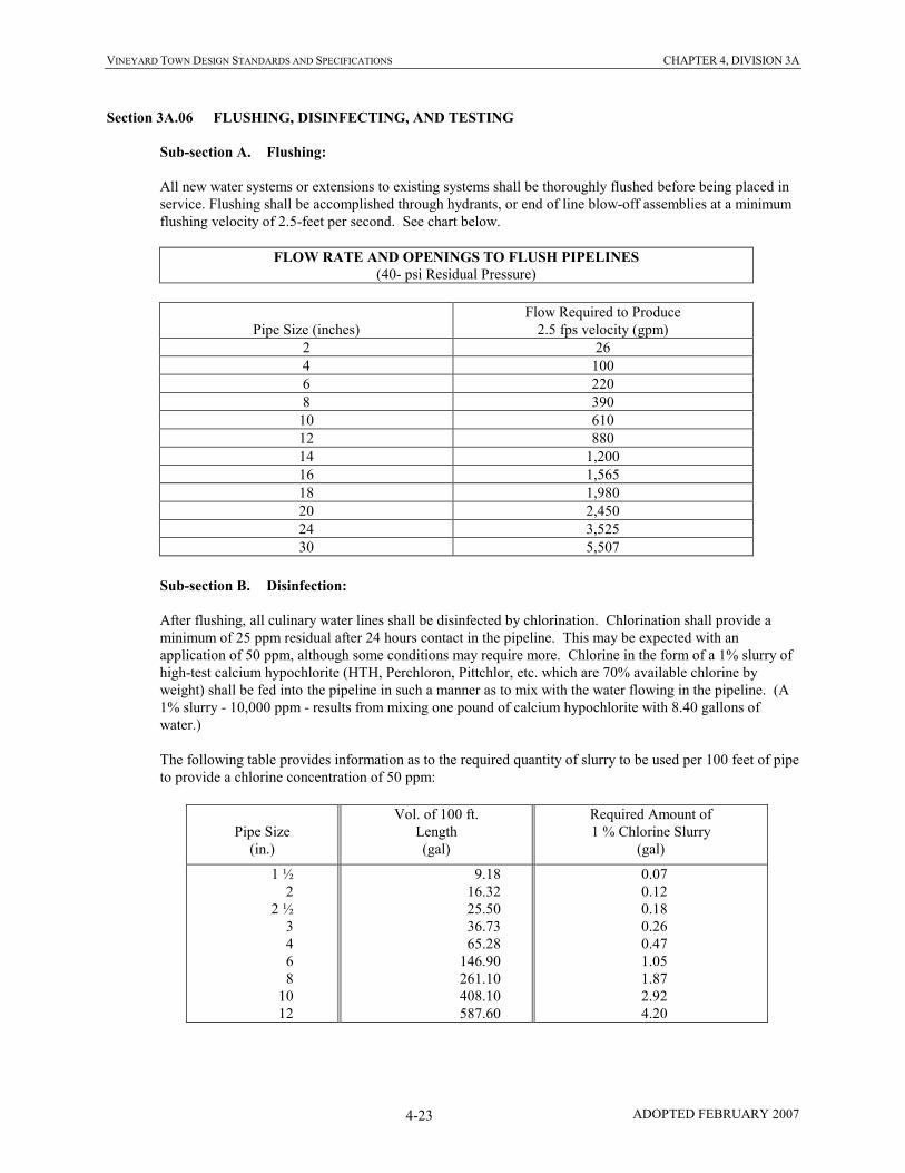
VINEYARD TOWN DESIGN STANDARDS AND SPECIFICATIONS CHAPTER 4, DIVISION 3A
ADOPTED FEBRUARY 2007 4-23
Section 3A.06 FLUSHING, DISINFECTING, AND TESTING
Sub-section A. Flushing:
All new water systems or extensions to existing systems shall be thoroughly flushed before being placed in
service. Flushing shall be accomplished through hydrants, or end of line blow-off assemblies at a minimum
flushing velocity of 2.5-feet per second. See chart below.
FLOW RATE AND OPENINGS TO FLUSH PIPELINES
(40- psi Residual Pressure)
Pipe Size (inches)
Flow Required to Produce
2.5 fps velocity (gpm)
2 26
4 100
6 220
8 390
10 610
12 880
14 1,200
16 1,565
18 1,980
20 2,450
24 3,525
30 5,507
Sub-section B. Disinfection:
After flushing, all culinary water lines shall be disinfected by chlorination. Chlorination shall provide a
minimum of 25 ppm residual after 24 hours contact in the pipeline. This may be expected with an
application of 50 ppm, although some conditions may require more. Chlorine in the form of a 1% slurry of
high-test calcium hypochlorite (HTH, Perchloron, Pittchlor, etc. which are 70% available chlorine by
weight) shall be fed into the pipeline in such a manner as to mix with the water flowing in the pipeline. (A
1% slurry - 10,000 ppm - results from mixing one pound of calcium hypochlorite with 8.40 gallons of
water.)
The following table provides information as to the required quantity of slurry to be used per 100 feet of pipe
to provide a chlorine concentration of 50 ppm:
Pipe Size
(in.)
Vol. of 100 ft.
Length
(gal)
Required Amount of
1 % Chlorine Slurry
(gal)
1 ½
2
2 ½
3
4
6
8
10
12
9.18
16.32
25.50
36.73
65.28
146.90
261.10
408.10
587.60
0.07
0.12
0.18
0.26
0.47
1.05
1.87
2.92
4.20

VINEYARD TOWN DESIGN STANDARDS AND SPECIFICATIONS CHAPTER 4, DIVISION 3A
ADOPTED FEBRUARY 2007 4-24
During the process of chlorinating the pipeline, operate all valves and other pipeline appurtenances several
times to provide sufficient contact with the chlorinating agent. Following chlorination, drain and thoroughly
flush the water line according to Section A above. The Public Works Representative shall obtain a water
sample, upon which the Town will have a bacteriological test performed. The Contractor/Owner shall pay the
cost of the bacteriological test. Rechlorinate the water line and retest the water, if necessary, until the results of
the bacteriological test are satisfactory.
Disinfection shall conform to the requirements of AWWA C651-86 (or latest edition).
Sub-section C. Pressure Test:
All newly laid pipes or any valved section thereof shall be subjected to a hydrostatic pressure. A leakage
test shall be conducted concurrently with the pressure test.
1) Test Pressure Restrictions: Test pressures shall,
i. Not be less than 1.5 times the static pressure at the highest point along the test section.
ii. Not exceed pipe or thrust restraint design pressures.
iii. Be of at least 2-hour duration.
iv. Not vary by more than plus or minus five (+ 5) psi for the duration of the test.
v. Not exceed twice the rated pressure of the valves or hydrants when the pressure boundary of the
test section includes closed gate valves or hydrants.
vi. Not exceed the rated pressure of the valves when the test boundary of the test section includes
closed, resilient-seated gate valves or butterfly valves.
2) Pressurization: Each valved section of pipe shall be slowly filled with water and the specified test
pressure, based on the elevation of the lowest point of the line or section under test and corrected to the
elevation of the test gage, shall be applied by means of a pump connected to the pipe in a manner
satisfactory to the Public Works Representative/Engineer.
3) Air Removal: Before applying the specified test pressure, air shall be expelled completely from the
pipe, valves, and hydrants. If permanent air vents are not located at all high points, the
Owner/Contractor shall install corporation cocks at such points so that the air can be expelled as the
line is filled with water. After all the air has been expelled, the corporation cocks shall be closed and
the test pressure applied. At the conclusion of the pressure test, the corporation cocks shall be removed
and plugged.
4) Examination: All exposed pipe, fittings, valves, hydrants, and joints shall be examined carefully during
the test. Any damaged or defective pipe, fittings, valves, or hydrants that are discovered following the
pressure test shall be repaired or replaced with sound materials and the test shall be repeated until it is
satisfactory to the Owner.

VINEYARD TOWN DESIGN STANDARDS AND SPECIFICATIONS CHAPTER 4, DIVISION 3A
ADOPTED FEBRUARY 2007 4-25
Sub-section D. Leakage Test:
A leakage test shall be conducted concurrently with the pressure test.
1) Leakage Defined: Leakage shall be defined as the quantity of water that must be supplied into the
newly laid pipe, or any valved section thereof, to maintain pressure within 5 psi of the specified test
pressure after the air in the pipeline has been expelled and the pipe has been filled with water.
2) Allowable Leakage: No pipe installation will be accepted if the leakage is greater than that determined
by the following formula:
L = SD(P)0.5
133,200
In which L is the allowable leakage, in gallons per hour; S is the length of pipeline tested in feet; D is
the nominal diameter of the pipe, in inches; and P is the average test pressure during the leakage test, in
pounds per square inch gage.
i. Allowable leakage at various pressures is shown in Table 1.
ii. When testing against closed metal-seated valves, an additional leakage per closed valve of 0.0078
gal/hr/in. of nominal valve size shall be allowed.
iii. When hydrants are in the test section, the test shall be made against the closed hydrant.
TABLE 1
Allowable Leakage per 1000 ft of Pipeline - gph
Average
Test Pressure
Nominal Pipe Diameter—in.
psi (Bar)
3 4 6 8 10 12 14 16 18 20 24 30 36 42 48 54
450 (31)
400 (28)
350 (24)
300 (21)
275 (19)
250 (17)
225 (16)
200 (14)
175 (12)
150 (10)
125 ( 9)
100 ( 7)
0.48
0.45
0.42
0.39
0.37
0.36
0.34
0.32
0.30
0.28
0.25
0.23
0.64
0.60
0.56
0.52
0.50
0.47
0.45
0.43
0.40
0.37
0.34
0.30
0.95
0.90
0.84
0.78
0.75
0.71
0.68
0.64
0.59
0.55
0.50
0.45
1.27
1.20
1.12
1.04
1.00
0.95
0.90
0.85
0.80
0.74
0.67
0.60
1.59
1.50
1.40
1.30
1.24
1.19
1.13
1.06
0.99
0.92
0.84
0.75
1.91
1.80
1.69
1.56
1.49
1.42
1.35
1.28
1.19
1.10
1.01
0.90
2.23
2.10
1.97
1.82
1.74
1.66
1.58
1.48
1.39
1.29
1.18
1.05
2.55
2.40
2.25
2.08
1.99
1.90
1.80
1.70
1.59
1.47
1.34
1.20
2.87
2.70
2.53
2.34
2.24
2.14
2.03
1.91
1.79
1.66
1.51
1.35
3.18
3.00
2.81
2.60
2.49
2.37
2.25
2.12
1.98
1.84
1.68
1.50
3.82
3.60
3.37
3.12
2.99
2.85
2.70
2.55
2.38
2.21
2.01
1.80
4.78
4.50
4.21
3.90
3.73
3.56
3.38
3.19
2.98
2.76
2.52
2.25
5.73
5.41
5.06
4.68
4.48
4.27
4.05
3.82
3.58
3.31
3.02
2.70
6.69
6.31
5.90
5.46
5.23
4.99
4.73
4.46
4.17
3.86
3.53
3.15
7.64
7.21
6.74
6.24
5.98
5.70
5.41
5.09
4.77
4.41
4.03
3.60
8.60
8.11
7.58
7.02
6.72
6.41
6.03
5.73
5.36
4.97
4.53
4.05
*If the pipeline under test contains sections of various diameters, the allowable leakage will be the sum of the computed leakage for each size.
**To obtain leakage in liters/hour, multiply the values in the table by 3.785.
3) Examination: All exposed pipe, fittings, valves, hydrants, and joints shall be examined carefully during
the test. Any damaged or defective pipe, fittings, valves, or hydrants that are discovered during the
leakage test shall be repaired or replaced with sound materials and the test shall be repeated. Repairs
or replacements to the pipeline and subsequent leakage testing shall be performed as necessary for the
pipeline to pass the leakage test.
Sub-section E. Acceptance of Installation:
Acceptance shall be determined on the basis of allowable leakage. If any test of pipe laid discloses leakage
greater than specified, the Owner/Contractor shall, at its own expense, locate and repair the defective
material until the leakage is within the specified allowance.
All visible leaks are to be repaired regardless of the amount of leakage.

VINEYARD TOWN DESIGN STANDARDS AND SPECIFICATIONS CHAPTER 4, DIVISION 4
ADOPTED FEBRUARY 2007 4-26
DIVISION 4
CONCRETE PIPE
Section 4.01 GENERAL
This section covers the requirements for concrete pipe materials and installation in sanitary sewer, storm
drain, and other gravity line construction.
Section 4.02 PIPE
Concrete pipe used in sewer line, storm drain line and other gravity line construction shall be reinforced
concrete pipe or non-reinforced concrete pipe, as required by design loading and fill heights and as follows:
Sub-section A. Reinforced Concrete Pipe:
All reinforced concrete pipe used in the construction shall be of the rubber gasket type, bell and spigot joint
design, conforming to the requirements of the latest revision of ASTM Designation C76. Pipe class shall be
as shown on the Drawings. The minimum joint length of all pipes provided shall be 7 1/2 feet. All pipe 12-
inch diameter and larger shall be reinforced concrete.
Sub-section B. Non-Reinforced Concrete Pipe:
All non-reinforced concrete pipe used in the construction shall be of the rubber gasket type, bell and spigot
joint design, conforming to the requirements of the latest revision of ASTM Designation C14. Pipe class
shall be as shown on the Drawings. The minimum joint length for pipe shall be four feet for pipe up to ten
inches and seven and a half feet for all other pipe.
Sub-section C. Bell and Spigot Joints:
Bell and spigot joints, including rubber gaskets, shall conform to the requirements of the latest revision of
ASTM Designation C443. The pipe joint shall be so designed as to provide for self-centering, and when
assembled, to compress the gasket to form a water tight seal. The gasket shall be confined in a groove on
the spigot, so that pipe movement or hydrostatic pressure cannot displace the gasket.
Sub-section D. Minimum Size and Slope Requirements:
In no case shall sanitary sewer mains be less than eight inches in diameter. Sewers shall be laid with
uniform slope between manholes. All sewers shall be designed and constructed to give mean velocities of
not less than 2 feet per second when flowing full, based on Manning’s formula using an n value of .013.
Absolute minimum slope allowed shall be those published by the Utah Department of Environmental
Quality, Division of Water Quality as Administrative Rules for Design Requirements for Wastewater
Collection, Treatment and Disposal System, R317-3, Table R317-3-2.3 (D)(4) Minimum Slopes.
Whenever possible the slope should exceed 0.006 ft/ft. The pipe should be sized to meet anticipated
hydraulic loads, increasing the pipe size to reduce the minimum slope requirements shall not be allowed.
Sewer slopes shall not exceed 0.12 ft/ft, drop manholes shall be used when steeper slopes are needed, drop
manholes shall be used to keep line grade below maximum grade allowed.

VINEYARD TOWN DESIGN STANDARDS AND SPECIFICATIONS CHAPTER 4, DIVISION 4
ADOPTED FEBRUARY 2007 4-27
Section 4.03 PIPE LAYING
All concrete pipe installation shall proceed upgrade on a stable foundation, with joints closely and
accurately fitted. Rubber gaskets shall be fitted properly in place, and care shall be taken in joining the pipe
sections to avoid twisting of gaskets. Joints shall be clean and dry, and a joint lubricant as recommended by
the pipe supplier shall be applied uniformly to the mating joint surfaces to facilitate easy positive joint
closure.
Pipe shall be installed with uniform bearing under the full length of the barrel, with suitable excavations
being made to receive pipe bells.
Select material shall be compacted around the pipe to firmly bed the pipe in position. If adjustment of
position of a pipe length is required after being laid, it shall be removed and re-jointed as for a new pipe.
When laying is not in progress, the ends of the pipe shall be closed with a tight-fitting stopper to prevent the
entrance of foreign material.
In addition to the above requirements, all pipe installation shall comply with the specific requirements of the
pipe manufacturer.
Section 4.04 GRAVEL FOUNDATION FOR PIPE
Wherever the subgrade material does not afford a sufficiently solid foundation to support the pipe and
superimposed load, or where groundwater must be drained, the subgrade shall be excavated to such depth as
may be necessary and replaced with crushed rock or gravel compacted into place.
Gravel for concrete pipe foundation shall be clean crushed rock or gravel with one hundred percent (100%)
less than two-inch (2") and a maximum of five percent (5%) less than one-half-inch (1/2”).
Section 4.05 INSTALLATION REQUIREMENTS FOR LINE AND GRADE
All concrete pipe shall be installed accurately to the defined line and grade with the following limits:
Variance from established line and grade shall not be greater than one-sixteenth (1/16) inch per inch of pipe
diameter in ten feet, and not to exceed one-half inch in ten feet, provided that such variation does not result
in a level or reverse sloping invert; provided also that variation in the invert elevation between adjoining
ends of pipe, due to non-concentricity of joining surface and pipe interior surfaces, does not exceed
one-sixty-fourth (1/64) inch per inch of pipe diameter, or one-half (1/2) inch maximum.
Section 4.06 PIPE BEDDING
All pipes shall be protected from lateral displacement and possible damage resulting from impact or
unbalanced loading during backfilling operations by being adequately bedded.
A groove shall be excavated in the bottom of the trench to receive the bottom quadrant of the pipe. Before
preparing the groove, the trench bottom shall be excavated or filled and compacted to an elevation
sufficiently above the grade of the pipe so that, when completed, the pipe will be true to line and grade.
Bell holes shall be excavated so that only the barrel of the pipe receives bearing from the trench bottom.
Pipe bedding materials placed at any point below the mid-point of the pipe shall be deposited and
compacted in layers not to exceed ten inches (10") in uncompacted depth. Deposition and compaction of
bedding materials shall be done simultaneously and uniformly on both sides of the pipe. Compaction shall
be accomplished with hand or mechanical compactors. All bedding materials shall be placed in the trench
in such a manner that they will be scattered alongside the pipe and not dropped into the trench in compact
masses. Bedding materials shall be loose earth, free from lumps; sand or gravel, free from rocks larger than
two-inch (2") diameter. All materials shall be free from roots, sod, or other vegetable matter.
VINEYARD TOWN DESIGN STANDARDS AND SPECIFICATIONS CHAPTER 4, DIVISION 4
ADOPTED FEBRUARY 2007 4-28
In the event trench materials are not satisfactory for pipe bedding, modified bedding will be required.
Modified bedding shall consist of placing compacted granular material on each side of and to the level of
twelve inches (12") above the top of the pipe.
Modified bedding material shall be graded as follows: One-hundred percent (100%) passing a one and one-
half inch (1-1/2") screen and five percent (5%) passing a No. 4 sieve.
Section 4.07 TESTS
The Owner/Contractor will be required to conduct an air test and displacement test in the presence of the
Public Works Representative/Engineer or his representative. If these tests prove to be inconclusive, any or
all of the other required tests shall be conducted in the presence of the Public Works
Representative/Engineer or his representative. Tests shall be performed as follows:
Sub-section A. Displacement Test:
In conducting the displacement test a light will be flashed between manholes or, if the manholes have not as
yet been constructed, between the locations of the manholes, by means of a flashlight or by reflecting
sunlight with a mirror. If the illuminated interior of the pipe shows broken, misaligned or displaced pipe or
other defects, the defects designated by the Public Works Representative/Engineer shall be remedied at the
Owner/Contractor's expense.
Sub-section B. Infiltration Test:
The Owner/Contractor shall furnish labor, equipment, and materials, including pumps, and shall assist the
Public Works Representative/Engineer in making infiltration tests of the completed line before it can be
placed into service. The Owner/Contractor shall furnish and install the measuring weirs or other measuring
devices. The length of line to be tested at any time shall be subject to the approval of the Public Works
Representative/Engineer. The maximum allowable infiltration shall not exceed one-hundred-fifty (150)
gallons per inch diameter per mile per twenty-four hours (24 hrs) for all installed pipe. If the quantity of
infiltration is in excess of the maximum allowable, the leaking joints shall be repaired to the satisfaction of
the Public Works Representative/Engineer at the expense of the Owner/Contractor.
Sub-section C. Exfiltration Test:
The Owner/Contractor shall furnish labor, equipment, and materials, including pumps, and shall assist the
Public Works Representative/Engineer in making ex-filtration tests of the completed line before it can be
placed into service. The length of line to be tested at one time shall be limited to the length between
adjacent manholes. The maximum allowable ex-filtration shall not exceed one-hundred-fifty (150) gallons
per inch diameter per mile per 24 hours for all installed pipe. The end of the line, which projects into the
manhole, shall be plugged. The pipe shall then be filled with water from the upper manhole, and the line
maintained under a light pressure of four feet (4') of head. The inflow of water necessary to maintain this
head shall be recorded as the leakage of the system. If the quantity of ex-filtration is in excess of the
maximum allowable, the leaking joints shall be repaired to the satisfaction of the Public Works
Representative/Engineer at the expense of the Owner/Contractor.
Sub-section D. Air Testing:
The Owner/Contractor or his representative (a qualified firm or individual agreed upon by the Public Works
Representative/Engineer and the Owner/Contractor) shall furnish labor, equipment, and materials, including
pumps and compressors, and shall perform, in the presence of the Public Works Representative/Engineer,
air tests of the completed pipe before it can be placed in service. Each section of sanitary sewer pipeline
between manholes shall be tested after all the four-inch service laterals (and plugs) have been installed.
Each test section shall be pressurized to 4.0 psi. For the purpose of stabilizing the air pressure in each test

VINEYARD TOWN DESIGN STANDARDS AND SPECIFICATIONS CHAPTER 4, DIVISION 4
ADOPTED FEBRUARY 2007 4-29
section, the 4.0 psi pressure shall be maintained for a two-minute period. Each test section shall then be re-
pressurized to 4.0 psi for a period of four minutes. The test section shall be accepted if, after four minutes,
the pressure gauge indicates 3.5 psi or greater. Failure of the Owner/Contractor's testing equipment to
properly function shall render the test unacceptable. All faulty sections of pipeline shall be repaired and re-
tested until the minimum air testing requirements have been met.
Section 4.08 MANHOLE CONNECTIONS
Concrete pipe connections to manholes shall be achieved by use of manhole coupling adapters, rubber gaskets,
positive seal gasket system with 300 series nonmagnetic corrosion-resistant steel bands, or grouting a bell or spigot
pipe at the appropriate locations. Connections shall meet the requirements of Division 5 MANHOLES.
Section 4.09 SEWER SERVICE LATERALS
New service laterals shall be constructed with materials and procedures as specified herein.
Existing service laterals shall be constructed with materials compatible with the existing laterals with appropriate
connections for joining the ends of existing laterals.
All laterals shall be four-inch (4") in diameter unless shown otherwise.
Sub-section A. Extent and Location of Laterals:
New sewer laterals installed to lots shall be located ten feet (10’) uphill of the lowest front property corner.
Service laterals shall extend from the sewer main to a point ten feet (10') beyond the street right-of-way line
unless shown or staked otherwise. A two-inch (2") by four-inch (4") by six-foot (6') marker, with the top
twelve inches (12") paintedgreen, shall be installed to clearly mark the end of each lateral line. In addition
to the marker, the Owner/Contractor shall station (give a distance) the location of the lateral connection to
the main from the nearest downstream manhole. Laterals shall be capped with a cap suitable to withstand
test pressure and prevent any leakage into or out of the lateral.
When an existing sewer lateral is encountered along the line and grade of a new pipeline it shall be
relocated using appropriate pipe and fittings and graded to insure adequate slope to drain properly.
Minimum slope shall be one-quarter-inch (1/4") per foot.
Sub-section B. Excavation and Backfill:
Trench excavation and backfill shall conform to the applicable paragraphs of Division 2 and the bedding
requirements of this Division.
Sub-section C. Pipe:
Pipe used for new service laterals shall be PVC Plastic Pipe conforming to ASTM D3034 SDR 35.
Sub-section D. Connection to Main:
Connection to a new main shall be made using a precast wye or tee installed in the main line at time of
installation with a 4-inch PVC adapter or rubber gasket into which the 4-inch PVC lateral is inserted to form
a water tight connection. In pipes 12 inches and larger the connection may be made using a cored hole in
the pipe and a rubber boot. Recommendations of the manufacturer of the materials used shall be carefully
followed.
Connections onto existing sewer mains shall be made with field installed service saddles (gasketed and
clamped). All connections by field installed service saddles on existing sewer mains shall be done with a
sewer tapping machine and all required fittings and materials. Connections shall be made as shown on the

VINEYARD TOWN DESIGN STANDARDS AND SPECIFICATIONS CHAPTER 4, DIVISION 4
ADOPTED FEBRUARY 2007 4-30
Standard Drawing and at the location specified herein, shown on the improvement drawings or as staked in
the field.
Sub-section E. Cover Over Sewer Lateral Lines:
There shall be a minimum of 3 feet of cover over all sewer lateral lines (3’6” minimum at property line.)
Sub-section F. Sewer Clean Outs:
There shall be a maximum distance of 5 feet from the foundation wall to the first exterior clean out with a
maximum distance between clean-outs of one hundred (100) feet. There shall be a clean out when a
combination of bends is ninety degrees (90o) or greater
Sub-section G. Testing:
The service laterals shall be tested as a part of the sewer main to which they are connected.
Sub-section H. Damage and Repair of Sewers and Appurtenances:
The Owner/Contractor shall be responsible for the protection of existing improvements, and any damage
resulting from its operations shall be its sole responsibility.
Damage to the sewers, laterals, or appurtenances shall be repaired by acceptable and approved methods.

VINEYARD TOWN DESIGN STANDARDS AND SPECIFICATIONS CHAPTER 4, DIVISION 4A
ADOPTED FEBRUARY 2007 4-31
DIVISION 4A
PVC PLASTIC PIPE
Section 4A.01 GENERAL
This section covers the requirements for PVC plastic sewer pipe materials and installation in sanitary sewer, storm
drain, and other gravity line construction.
Section 4A.02 PIPE
PVC gravity sewer pipe and fittings shall conform to ASTM D3034, for diameters from four-inch (4") to fifteen-inch
(15") and ASTM F679 for eighteen-inch (18") to twenty-seven-inch (27"), with integral bell gasket joints. Rubber
gaskets shall be factory installed and conform to ASTM F477. Pipe shall be made of PVC plastic having a cell
classification of 12454A or 13364B (with minimum tensile modulus of 500,000 PSI) as defined in ASTM D1784
and shall have a SDR of 35 and minimum pipe stiffness of 46PSI according to ASTM test D2412.
Pipe shall be installed in compliance with ASTM D2321 and the manufacturer's requirements.
Sub-section A. Minimum Size and Slope Requirements:
In no case shall sanitary sewer mains be less than eight inches in diameter. Sewers shall be laid with
uniform slope between manholes. All sewers shall be designed and constructed to give mean velocities of
not less than 2 feet per second when flowing full, based on Manning’s formula using an n value of .013.
Absolute minimum slope allowed shall be those published by the Utah Department of Environmental
Quality, Division of Water Quality as Administrative Rules for Design Requirements for Wastewater
Collection, Treatment and Disposal System, R317-3, Table R317-3-2.3 (D)(4) Minimum Slopes.
Whenever possible the slope should exceed 0.006 ft/ft. The pipe should be sized to meet anticipated
hydraulic loads, increasing the pipe size to reduce the minimum slope requirements shall not be allowed.
Sewer slopes shall not exceed 0.12 ft/ft, drop manholes shall be used when steeper slopes are needed, drop
manholes shall be used to keep line grade below maximum grade allowed.
Section 4A.03 FITTINGS
Fittings shall be made of PVC plastic conforming to ASTM D1784 and a cell classification as outlined in ASTM
D3034.
Section 4A.04 PIPE LAYING
All pipe installation shall proceed upgrade on a stable foundation, with joints closely and accurately fitted. Joints
shall be clean and dry, and a joint lubricant as recommended by the pipe supplier shall be applied uniformly to the
mating joint surfaces to facilitate easy positive joint closure.
Pipe shall be installed with uniform bearing under the full length of the barrel, with suitable excavations being made
to receive pipe bells.
Select material shall be compacted around the pipe to firmly bed the pipe in position. Haunching material (bed to
springline) should be carefully worked under the haunches of the pipe and compacted from the pipe to the trench
wall or two and one half (2-1/2) pipe diameters on each side of the pipe to ensure support. If adjustment of position
of a pipe length is required after being laid, it shall be removed and re-jointed as for a new pipe. When pipe laying is
not in progress, the ends of the pipe shall be closed with a tight-fitting stopper to prevent the entrance of foreign
material.
In addition to the above requirements, all pipe installation shall rigidly adhere to the specific requirements of the
pipe manufacturer.

VINEYARD TOWN DESIGN STANDARDS AND SPECIFICATIONS CHAPTER 4, DIVISION 4A
ADOPTED FEBRUARY 2007 4-32
Section 4A.05 GRAVEL FOUNDATION FOR PIPE
Wherever the subgrade material does not afford a sufficiently solid foundation to support the pipe and superimposed
load, and where groundwater must be drained, the subgrade shall be excavated to such depth as may be necessary
and replaced with crushed rock or gravel compacted into place.
Gravel for PVC pipe foundation shall be clean crushed rock or gravel with one hundred percent (100%) passing a
one-inch (1") screen and less than five percent (5%) passing a No. 4 sieve.
Section 4A.06 INSTALLATION REQUIREMENTS FOR LINE AND GRADE
All PVC pipe shall be installed accurately to the defined line and grade with the following limits:
a) Variance from established line and grade shall not be greater than one-sixteenth (1/16) inch per inch of pipe
diameter in ten feet, and not to exceed one-half inch in ten feet, provided that such variation does not result
in a level or reverse sloping invert; provided also that variation in the invert elevation between adjoining
ends of pipe, due to non-concentricity of joining surface and pipe interior surfaces, does not exceed
one-sixty-fourth (1/64) inch per inch of pipe diameter, or one-half (1/2) inch maximum.
Section 4A.07 PIPE BEDDING
All pipe sewers and drains shall be protected from lateral displacement and possible damage resulting from impact or
unbalanced loading during backfilling operations by being adequately bedded.
A groove shall be excavated in the bottom of the trench to receive the bottom quadrant of the pipe. Before preparing
the groove, the trench bottom shall be excavated or filled and compacted to an elevation sufficiently above the grade
of the pipe so that, when completed, the pipe will be true to line and grade. Bell holes shall be excavated so that
only the barrel of the pipe receives bearing from the trench bottom.
Pipe bedding materials placed at any point below the mid-point of the pipe shall be deposited and compacted in
layers not to exceed ten inches (10") in uncompacted depth. Deposition and compaction of bedding materials shall
be done simultaneously and uniformly on both sides of the pipe. Compaction shall be accomplished with hand or
mechanical compactors. All bedding materials shall be placed in the trench with hand tools or other approved
method in such a manner that they will be scattered alongside the pipe and not dropped into the trench in compact
masses. Bedding materials shall be loose earth, free from lumps; sand or gravel, free from rocks larger than one-inch
(1") diameter; with all materials free from roots, sod, or other vegetable matter.
In the event trench materials are not satisfactory for pipe bedding, modified bedding will be required. Modified
bedding shall consist of placing compacted granular material on each side of and to the level of twelve inches (12")
above the top of the pipe.
Modified bedding material shall be graded as follows: One-hundred percent (100%) passing a one and one-half inch
(1-1/2") screen and five percent (5%) passing a No. 4 sieve.
Section 4A.08 TESTS
The Owner/Contractor will be required to conduct an air test and displacement test in the presence of the Public
Works Representative/Engineer or his representative. If these tests prove to be inconclusive, any or all of the other
required tests shall be conducted in the presence of the Public Works Representative/Engineer or his representative.
Tests shall be performed as follows:
Sub-section A. Displacement Test:

VINEYARD TOWN DESIGN STANDARDS AND SPECIFICATIONS CHAPTER 4, DIVISION 4A
ADOPTED FEBRUARY 2007 4-33
In conducting the displacement test a light will be flashed between manholes or, if the manholes have not as
yet been constructed, between the locations of the manholes, by means of a flashlight or by reflecting
sunlight with a mirror. If the illuminated interior of the pipe shows broken, misaligned or displaced pipe or
other defects, the defects designated by the Public Works Representative/Engineer shall be remedied at the
Owner/Contractor's expense.
Sub-section B. Infiltration Test:
The Owner/Contractor shall furnish labor, equipment, and materials, including pumps, and shall assist the
Public Works Representative/Engineer in making infiltration tests of the completed sewer before it can be
placed into service. The Owner/Contractor shall furnish and install the measuring weirs or other measuring
devices. The length of line to be tested at any time shall be subject to the approval of the Public Works
Representative/Engineer. The maximum allowable infiltration shall not exceed one-hundred-fifty (150)
gallons per inch diameter per mile per twenty-four hours (24 hrs) for all installed sewer pipe. If the quantity
of infiltration is in excess of the maximum allowable, the leaking joints shall be repaired to the satisfaction
of the Public Works Representative/Engineer at the expense of the Owner/Contractor.
Sub-section C. Exfiltration Test:
The Owner/Contractor shall furnish labor, equipment, and materials, including pumps, and shall assist the
Public Works Representative/Engineer in making exfiltration tests of the completed sewer before it can be
placed into service. The length of line to be tested at one time shall be limited to the length between
adjacent manholes. The maximum allowable exfiltration shall not exceed one-hundred-fifty (150) gallons
per inch diameter per mile per 24 hours for all installed sewer pipe. The end of the sewer line, which
projects into the manhole, shall be plugged. The pipe shall then be filled with water from the upper
manhole, and the line maintained under a light pressure of four feet (4') of head. The inflow of water
necessary to maintain this head shall be recorded as the leakage of the system. If the quantity of exfiltration
is in excess of the maximum allowable, the leaking joints shall be repaired to the satisfaction of the Public
Works Representative/Engineer at the expense of the Owner/Contractor.
Sub-section D. Air Testing:
The Owner/Contractor or his representative (a qualified firm or individual agreed upon by the Public Works
Representative/Engineer and the Owner/Contractor) shall furnish labor, equipment, and materials, including
pumps and compressors, and shall perform, in the presence of the Public Works Representative/Engineer,
air tests of the completed pipe before it can be placed in service. Each section of sanitary sewer pipeline
between manholes shall be tested after all the service laterals (and plugs) have been installed. Each test
section shall be pressurized to four (4.0) psi. For the purpose of stabilizing the air pressure in each test
section, the four (4.0) psi pressure shall be maintained for a two-minute period. Each test section shall then
be re-pressurized to 4.0 psi for a period of four minutes. The test section shall be accepted if, after four
minutes, the pressure gauge indicates 3.5 psi or greater. Failure of the Owner/Contractor's testing
equipment to properly function shall render the test unacceptable. All faulty sections of pipeline shall be
repaired and re-tested until the minimum air testing requirements have been met.
Section 4A.09 MANHOLE CONNECTIONS
PVC pipe connections to manholes shall be achieved by use of manhole coupling adapters, rubber gaskets, or
positive seal gasket system with 300 series nonmagnetic corrosion-resistant steel bands. PVC may not be grouted
directly to concrete. Connections shall meet the requirements of Division 5 MANHOLES.

VINEYARD TOWN DESIGN STANDARDS AND SPECIFICATIONS CHAPTER 4, DIVISION 4A
ADOPTED FEBRUARY 2007 4-34
Section 4A.10 SEWER LATERAL CONNECTIONS
All sewer lateral connections onto new sewer mains shall be made through preformed tee fittings installed in the
main line at the time of main line installation.
Connections onto existing sewer mains shall be made with field installed service saddles (gasketed and clamped).
All connections by field installed service saddles on existing sewer mains shall be done with a sewer tapping
machine and all required fittings and materials. Connections shall be made as shown on the Standard Drawing and at
the location specified herein, shown on the improvement drawings or as staked in the field.
Section 4A.11 SEWER SERVICE LATERALS
New service laterals shall be constructed with materials and procedures as specified herein.
Existing service laterals shall be constructed with materials compatible with the existing laterals with appropriate
connections for joining the ends of existing laterals.
All laterals shall be four inch (4") in diameter unless shown otherwise.
Sub-section A. Extent of Laterals and Location of Laterals:
New sewer laterals installed to lots shall be located ten feet (10’) uphill of the lowest front property corner.
Service laterals shall extend from the sewer main to a point ten feet (10') beyond the street right-of-way line
unless shown or staked otherwise. A two-inch (2") by four-inch (4") by six-foot (6') marker, with the top
twelve inches (12") painted green, shall be installed to clearly mark the end of each lateral line. In addition
to the marker, the Owner/Contractor shall station (give a distance) the location of the lateral connection to
the main from the nearest downstream manhole. Laterals shall be capped with a cap suitable to withstand
test pressure and prevent any leakage into or out of the lateral.
When an existing sewer lateral is encountered along the line and grade of a new pipeline it shall be
relocated using appropriate pipe and fittings and graded to insure adequate slope to drain properly.
Minimum slope shall be one-quarter-inch (1/4") per foot.
Sub-section B. Excavation and Backfill:
Trench excavation and backfill shall conform to the applicable paragraphs of Division 2 and the bedding
requirements of this Division.
Sub-section C. Pipe:
Pipe used for new service laterals shall be PVC Plastic Pipe conforming to ASTM D3034 SDR 35.
Sub-section D. Connection to Main:
Connections to the main shall be made as specified in Section 4A.10 SEWER LATERAL
CONNECTIONS. Recommendations of manufacturer of the materials used shall be carefully followed.
Sub-section E. Cover Over Sewer Lateral Lines:
There shall be a minimum of 3 feet of cover over all sewer lateral lines (3’6” minimum at property line.)
Sub-section F. Sewer Clean Outs:
There shall be a maximum distance of 5 feet from the foundation wall to the first exterior clean out with a
maximum distance between clean-outs of one hundred (100) feet. There shall be a clean out when a
combination of bends is ninety degrees (90o) or greater

VINEYARD TOWN DESIGN STANDARDS AND SPECIFICATIONS CHAPTER 4, DIVISION 4A
ADOPTED FEBRUARY 2007 4-35
Sub-section G. Testing:
The service laterals shall be tested as a part of the sewer main to which they are connected.
Sub-section H. Damage and Repairs of Sewers and Appurtenances:
The Owner/Contractor shall be responsible for the protection of existing improvements, and any damage
resulting from its operations shall be its sole responsibility.
Damage to the sewers, laterals, or appurtenances shall be repaired by acceptable and approved methods.
Section 4A.12 "GO/NO-GO" MANDREL PROOF TESTING
Not less than thirty (30) days after installation of the flexible sewer or drain pipe, the Owner/Contractor shall test the
buried pipe to insure that ring-deflection of the pipe does not exceed five percent (5%) of the pipe's specified
minimum inside diameter (ID). This proof test shall establish that the Owner/Contractor has installed the flexible
pipe in full compliance with the Project Specifications thereby providing required pipe/soil structural strength.
The Owner/Contractor, with Inspector present, shall pull a "Go/No-Go" Mandrel, inspected and approved by the
Public Works Representative/Engineer, through the full length of installed flexible pipe. The Mandrel shall be
fabricated from suitable metal with a minimum of nine (9) properly sized radial fins mounted upon a center pulling
shaft. In any case, the Mandrel shall be provided with an odd number of rigidly mounted radial fins. The Mandrel
shall be provided with a proof-sizing ring that can demonstrate that the Mandrel's minimum outside diameter (OD) is
not less than ninety-five percent (95%) of the specified minimum inside diameter of the installed flexible pipe. The
Mandrel shall be pulled by the Owner/Contractor through one hundred percent (100%) of the installed flexible pipe
without using mechanical equipment. Failure of the Mandrel to pass through a pipeline shall be deemed evidence of
inadequate installation by the Owner/Contractor not in compliance with the Project Specifications.
The Public Works Representative/Engineer may require, if deemed appropriate or necessary, additional proof testing
of designated lengths of the buried flexible pipe approximately one year (1 yr.) after installation but prior to the
expiration of the Owner/Contractor's Maintenance Bond. The flexible pipeline shall be cleaned adequately prior to
performing the "Go/No-Go" Mandrel ring deflection proof test. The Owner/Contractor, with Inspector present, shall
pull a Mandrel, approved by the Public Works Representative/Engineer, through the designated length of pipeline
without using mechanical equipment. Failure of the Mandrel to pass through the pipeline shall be deemed evidence
of inadequate installation by the Owner/Contractor not in compliance with the Project Specifications.

VINEYARD TOWN DESIGN STANDARDS AND SPECIFICATIONS CHAPTER 4, DIVISION 4B
ADOPTED FEBRUARY 2007 4-36
DIVISION 4B
POLYETHYLENE CORRUGATED PIPE
Section 4B.01 GENERAL
This section covers the requirements for high-density polyethylene corrugated pipe with integrally formed smooth
interior for use in storm drains.
Section 4B.02 PIPE
This specification is applicable to nominal sizes 12 - 36 inch diameter. Requirements for test methods, dimensions,
and markings are those found in AASHTO Designation M-294.
Pipe and fittings shall be made of polyethylene compounds that meet or exceed the requirements of Type III,
Category 4 or 5, Grade P33 or P34, Class C per ASTM Designation D1248 with the applicable requirements defined
in ASTM D1248. Clean reworked material may be used.
Minimum parallel plate pipe stiffness values at 5% deflection shall be as follows:
Diameter Pipe Stiffness*
12" 45 psi
15" 42 psi
18" 40 psi
24" 34 psi
30" 28 psi *Per ASTM Test
36" 22 psi Method D2412
The pipe and fittings shall be free of foreign inclusions and visible defects. The ends of the pipe shall be cut
squarely and cleanly so as not to adversely effect joining.
The nominal size for the pipe and fittings is based on the nominal inside diameter of the pipe. Corrugated fittings
maybe either molded or fabricated by the manufacturer. Fittings produced by manufacturers other than the supplier
of the pipe shall not be permitted without the approval of the Project Public Works Representative/Engineer.
A manufacturers' certification that the product was manufactured, tested, and supplied in accordance with this
specification shall be furnished to the Project Public Works Representative/Engineer upon request.
Pipe installation shall be in accordance with ASTM Recommended Practice D2321 and the manufacturer's
requirements.
Section 4B.03 JOINTS
Joints shall be made with split couplings, corrugated to match the pipe corrugations, and shall engage a minimum of
6 corrugations for 12" - 24" diameter and 4 corrugations for 30" and 36" diameter pipe.
Section 4B.04 PERFORATIONS
All perforated pipe used in the construction shall have either circular or slotted perforations. Circular perforations
shall not be more that 5/16 in. nor less than 3/16 in. in diameter, and arranged in rows parallel to the axis of the pipe.
Perforations shall be 3 in. center-to-center, along rows. The spigot or tongue end shall not be perforated for a length
equal to the depth of the socket, or depth of the groove plus 3/4 in. and perforations shall continue at uniform
spacing along the entire length of the barrel. There shall be a total of 8 rows for an 18-inch pipe. The rows shall be

VINEYARD TOWN DESIGN STANDARDS AND SPECIFICATIONS CHAPTER 4, DIVISION 4B
ADOPTED FEBRUARY 2007 4-37
spaced over not more than 165 deg of circumference. Rows shall be symmetrically arranged with respect to the
intended top of bottom of the pipe.
Slots shall be circumferential in direction, not more than 3/16 in. or less than 1/8 in. in width, and 3 in. long. The
slots shall be spaced 6 in. apart. There shall be two rows of slots, spaced 120o apart. The distance from the spigot
end, or from the shoulder of the tongue end, to the first pair of slots shall be not more than 1 in. greater than the
specified slot spacing, nor less than 1 in. less than the specified slot spacing. Slots shall continue at uniform spacing
along the entire length of the barrel.
Section 4B.05 PIPE LAYING
All pipe installation shall proceed upgrade on a stable foundation, with joints closely and accurately fitted.
Pipe shall be installed with uniform bearing under the full length of the barrel, with suitable excavations being made
to receive pipe joints.
Select material shall be compacted around the pipe to firmly bed the pipe in position. Haunching material (bed to
springline) should be carefully worked under the haunches of the pipe and compacted from the pipe to the trench
wall, or two and one-half
(2-1/2) pipe diameters on each side of the pipe, to ensure support. If adjustment of position of a pipe length is
required after being laid, it shall be removed and re-jointed as for a new pipe. When pipe laying is not in progress,
the ends of the pipe shall be closed with a tight-fitting stopper to prevent the entrance of foreign material.
In addition to the above requirements, all pipe installation shall rigidly adhere to the specific requirements of the
pipe manufacturer.
Section 4B.06 GRAVEL FOUNDATION FOR PIPE
Wherever the subgrade material does not afford a sufficiently solid foundation to support the pipe and superimposed
load, and where groundwater must be drained, the subgrade shall be excavated to such depth as may be necessary
and replaced with crushed rock or gravel compacted into place.
Gravel for pipe foundation shall be clean crushed rock or gravel with one hundred percent (100%) passing a one-
inch (1") screen and less than five percent (5%) passing a No. 4 sieve.
Section 4B.07 INSTALLATION REQUIREMENTS FOR LINE AND GRADE
All pipe shall be installed accurately to the defined line and grade with the following limits:
a) Variance from established line and grade shall not be greater than one-sixteenth (1/16) inch per inch of pipe
diameter in ten feet, and not to exceed one-half inch in ten feet, provided that such variation does not result
in a level or reverse sloping invert; provided also that variation in the invert elevation between adjoining
ends of pipe, due to non-concentricity of joining surface and pipe interior surfaces, does not exceed
one-sixty-fourth (1/64) inch per inch of pipe diameter, or one-half (1/2) inch maximum.
Section 4B.08 PIPE BEDDING
All pipe sewers and drains shall be protected from lateral displacement and possible damage resulting from impact or
unbalanced loading during backfilling operations by being adequately bedded.
A groove shall be excavated in the bottom of the trench to receive the bottom quadrant of the pipe. Before preparing
the groove, the trench bottom shall be excavated or filled and compacted to an elevation sufficiently above the grade
of the pipe so that, when completed, the pipe will be true to line and grade. Joint holes shall be excavated so that
only the barrel of the pipe receives bearing from the trench bottom.

VINEYARD TOWN DESIGN STANDARDS AND SPECIFICATIONS CHAPTER 4, DIVISION 4B
ADOPTED FEBRUARY 2007 4-38
Pipe bedding materials placed at any point below the mid-point of the pipe shall be deposited and compacted in
layers not to exceed ten inches (10") in uncompacted depth. Deposition and compaction of bedding materials shall
be done simultaneously and uniformly on both sides of the pipe. Compaction shall be accomplished with hand or
mechanical compactors. All bedding materials shall be placed in the trench with hand tools or other approved
method in such a manner that they will be scattered alongside the pipe and not dropped into the trench in compact
masses. Bedding materials shall be loose earth, free from lumps; sand or gravel, free from rocks larger than one and
one-half inch (1-1/2") diameter; with all materials free from roots, sod, or other vegetable matter.
In the event trench materials are not satisfactory for pipe bedding, modified bedding will be required. Modified
bedding shall consist of placing compacted granular material on each side of and to the level of twelve inches (12")
above the top of the pipe.
Modified bedding material shall be graded as follows: One-hundred percent (100%) passing a No. 4 sieve and less
than five percent (5%) passing a No. 200 sieve.
Section 4B.09 TESTS
The Owner/Contractor will be required to conduct a displacement test in the presence of the Public Works
Representative/Engineer or his representative. If this test prove to be inconclusive, other required tests shall be
conducted in the presence of the Public Works Representative/Engineer or his representative. The test shall be
performed as follows:
Sub-section A. Displacement Test:
In conducting the displacement test a light will be flashed between manholes or, if the manholes have not as
yet been constructed, between the locations of the manholes, by means of a flashlight or by reflecting
sunlight with a mirror. If the illuminated interior of the pipe shows broken, misaligned, or displaced pipe or
other defects, the defects designated by the Public Works Representative/Engineer shall be remedied at the
Owner/Contractor's expense.
Section 4B.10 MANHOLE CONNECTIONS
Corrugated polyethylene pipe connections to manholes shall be achieved by use of manhole coupling adapters,
rubber boots with 300 series nonmagnetic corrosion-resistant steel bands, or grouted directly to concrete.
Section 4B.11 LATERAL CONNECTIONS
All lateral connections into new sewer mains shall be through preformed tee fittings installed in the main line or with
field installed service saddles. All connections by field installed service saddles on new or existing sewer mains
shall be done in accordance with manufacturer recommendations and with all required fittings and materials.
Connections shall be at the locations shown in the Drawings.

VINEYARD TOWN DESIGN STANDARDS AND SPECIFICATIONS CHAPTER 4, DIVISION 4C
ADOPTED FEBRUARY 2007 4-39
DIVISION 4C
POLYETHYLENE CORRUGATED PIPE
WITH WATER TIGHT JOINTS
Section 4C.01 GENERAL
This section covers the requirements for high density polyethylene corrugated pipe with integrally formed smooth
interior for use in storm drains with water tight joints.
Section 4C.02 PIPE
This specification is applicable to nominal sizes 4 - 18 inch diameter. Requirements for test methods, dimensions, and
markings are those found in AASHTO Designation M-252 and M-294 and ASTM F405 and F-667.
Pipe shall be made of polyethylene compounds that meet or exceed the requirements of Type III, Category 4 or 5, Grade
P33 or P34, Class C per ASTM Designation D1248 with the applicable requirements defined in ASTM D1248. Clean
reworked material may be used.
Minimum parallel plate pipe stiffness values shall be as follows:
Diameter Pipe Stiffness*
4" 50 psi
6" 50 psi
8" 50 psi
10" 50 psi
12" 45 psi *Per ASTM Test
15" 42 psi Method D2412
18" 40 psi
The pipe and fittings shall be free of foreign inclusions and visible defects. For pipe sizes 12" diameter and greater,
holes of any kind in the corrugation crests or sidewalls shall be considered unacceptable. The ends of the pipe shall be
cut squarely and cleanly so as not to adversely effect joining.
The nominal size for the pipe and fittings is based on the nominal inside diameter of the pipe. Fittings shall be molded
by the manufacturer. Fittings produced by manufacturers other than the supplier of the pipe shall not be permitted.
A manufacturer's certification that the product was manufactured, tested, and supplied in accordance with this
specification shall be furnished to the Project Public Works Representative/Engineer upon request.
Pipe installation shall be in accordance with ASTM Recommended Practice D2321 and the manufacturer's requirements.
Section 4C.03 FITTINGS
Fittings shall be molded from SDR-35 PVC pipe manufactured in accordance with the applicable requirements defined
in ASTM D3034.
Section 4C.04 PIPE LAYING
All pipe installation shall proceed upgrade on a stable foundation, with joints closely and accurately fitted.
Pipe shall be installed with uniform bearing under the full length of the barrel, with suitable excavations being made to
receive pipe joints.

VINEYARD TOWN DESIGN STANDARDS AND SPECIFICATIONS CHAPTER 4, DIVISION 4C
ADOPTED FEBRUARY 2007 4-40
Select material shall be compacted around the pipe to firmly bed the pipe in position. Haunching material (bed to
springline) should be carefully worked under the haunches of the pipe and compacted from the pipe to the trench wall or
two and one half (2-1/2) pipe diameters on each side of the pipe to ensure support. If adjustment of position of a pipe
length is required after being laid, it shall be removed and re-jointed as for a new pipe. When laying is not in progress,
the ends of the pipe shall be closed with a tight-fitting stopper to prevent the entrance of foreign material.
In addition to the above requirements, all pipe installation shall rigidly adhere to the specific requirements of the pipe
manufacturer.
Section 4C.05 GRAVEL FOUNDATION FOR PIPE
Wherever the subgrade material does not afford a sufficiently solid foundation to support the pipe and superimposed
load, or where groundwater must be drained, the subgrade shall be excavated to such depth as may be necessary and
replaced with crushed rock or gravel compacted into place.
Gravel for pipe foundation shall be clean crushed rock or gravel with one hundred percent (100%) passing a one-inch
(1") screen and less than five percent (5%) passing a No. 4 sieve.
Section 4C.06 INSTALLATION REQUIREMENTS FOR LINE AND GRADE
All pipe shall be installed accurately to the defined line and grade with the following limits:
a) Variance from established line and grade shall not be greater than one-sixteenth (1/16) inch per inch of pipe
diameter in ten feet, and not to exceed one-half inch in ten feet, provided that such variation does not result in a
level or reverse sloping invert; provided also that variation in the invert elevation between adjoining ends of
pipe, due to non-concentricity of joining surface and pipe interior surfaces, does not exceed one-sixty-fourth
(1/64) inch per inch of pipe diameter, or one-half (1/2) inch maximum.
Section 4C.07 PIPE BEDDING
All pipe sewers and drains shall be protected from lateral displacement and possible damage resulting from impact or
unbalanced loading during backfilling operations by being adequately bedded.
A groove shall be excavated in the bottom of the trench to receive the bottom quadrant of the pipe. Before preparing the
groove, the trench bottom shall be excavated or filled and compacted to an elevation sufficiently above the grade of the
pipe so that, when completed, the pipe will be true to line and grade. Joint holes shall be excavated so that only the
barrel of the pipe receives bearing from the trench bottom.
Pipe bedding materials placed at any point below the mid-point of the pipe shall be deposited and compacted in layers
not to exceed ten inches (10") in uncompacted depth. Deposition and compaction of bedding materials shall be done
simultaneously and uniformly on both sides of the pipe. Compaction shall be accomplished with hand or mechanical
compactors. All bedding materials shall be placed in the trench with hand tools or other approved method in such a
manner that they will be scattered alongside the pipe and not dropped into the trench in compact masses. Bedding
materials shall be loose earth, free from lumps; sand or gravel, free from rocks larger than one and one-half inch (1-1/2")
diameter; with all materials free from roots, sod, or other vegetable matter.
In the event trench materials are not satisfactory for pipe bedding, modified bedding will be required. Modified bedding
shall consist of placing compacted granular material on each side of and to the level of twelve inches (12") above the top
of the pipe.
Modified bedding material shall be graded as follows: One-hundred percent (100%) passing a No. 4 sieve and less than
five percent (5%) passing a No. 200 sieve.

VINEYARD TOWN DESIGN STANDARDS AND SPECIFICATIONS CHAPTER 4, DIVISION 4C
ADOPTED FEBRUARY 2007 4-41
Section 4C.08 TESTS
The Owner/Contractor will be required to conduct an air test and displacement test in the presence of the Public Works
Representative/Engineer or his representative. If these tests prove to be inconclusive, any or all of the other required
tests shall be conducted in the presence of the Public Works Representative/Engineer or his representative. Tests shall
be performed as follows:
Sub-section A. Displacement Test:
In conducting the displacement test a light will be flashed between manholes or, if the manholes have not as yet
been constructed, between the locations of the manholes, by means of a flashlight or by reflecting sunlight with
a mirror. If the illuminated interior of the pipe shows broken, misaligned or displaced pipe or other defects, the
defects designated by the Public Works Representative/Engineer shall be remedied at the Owner/Contractor's
expense.
Sub-section B. Infiltration Test:
The Owner/Contractor shall furnish labor, equipment, and materials, including pumps, and shall assist the
Public Works Representative/Engineer in making infiltration tests of the completed line before it can be placed
into service. The Owner/Contractor shall furnish and install the measuring weirs or other measuring devices.
The length of line to be tested at any time shall be subject to the approval of the Public Works
Representative/Engineer. The maximum allowable infiltration shall not exceed one-hundred-fifty (150) gallons
per inch diameter per mile per twenty-four hours (24 hrs) for all installed pipe. If the quantity of infiltration is
in excess of the maximum allowable, the leaking joints shall be repaired to the satisfaction of the Public Works
Representative/Engineer at the expense of the Owner/Contractor.
Sub-section C. Ex-filtration Test:
The Owner/Contractor shall furnish labor, equipment, and materials, including pumps, and shall assist the
Public Works Representative/Engineer in making ex-filtration tests of the completed line before it can be
placed into service. The length of line to be tested at one time shall be limited to the length between adjacent
manholes. The maximum allowable ex-filtration shall not exceed one-hundred-fifty (150) gallons per inch
diameter per mile per 24 hours for all installed pipe. The end of the line, which projects into the manhole, shall
be plugged. The pipe shall then be filled with water from the upper manhole, and the line maintained under a
light pressure of four feet (4') of head. The inflow of water necessary to maintain this head shall be recorded as
the leakage of the system. If the quantity of ex-filtration is in excess of the maximum allowable, the leaking
joints shall be repaired to the satisfaction of the Public Works Representative/Engineer at the expense of the
Owner/Contractor.
Sub-section D. Air Testing:
The Owner/Contractor or his representative (a qualified firm or individual agreed upon by the Public Works
Representative/Engineer and the Owner/Contractor) shall furnish labor, equipment, and materials, including
pumps and compressors, and shall perform, in the presence of the Public Works Representative/Engineer, air
tests of the completed pipe before it can be placed in service. Each section of sanitary sewer pipeline between
manholes shall be tested after all the four-inch service laterals (and plugs) have been installed. Each test
section shall be pressurized to 4.0 psi. For the purpose of stabilizing the air pressure in each test section, the
4.0 psi pressure shall be maintained for a two-minute period. Each test section shall then be repressurized to
4.0 psi for a period of four minutes. The test section shall be accepted if, after four minutes, the pressure gauge
indicates 3.5 psi or greater. Failure of the Owner/Contractor's testing equipment to properly function shall
render the test unacceptable. All faulty sections of pipeline shall be repaired and retested until the minimum air
testing requirements have been met.

VINEYARD TOWN DESIGN STANDARDS AND SPECIFICATIONS CHAPTER 4, DIVISION 4C
ADOPTED FEBRUARY 2007 4-42
Section 4C.09 MANHOLE CONNECTIONS
Corrugated polyethylene pipe connections to manholes shall be achieved by use of manhole coupling adapters, rubber
boots with 300 series nonmagnetic corrosion-resistant steel bands, or grouted directly to concrete.
Section 4C.10 LATERAL CONNECTIONS
All lateral connections into new sewer mains shall be through preformed tee fittings installed in the main line or with
field installed service saddles. All connections by field installed service saddles on new or existing sewer mains shall be
done in accordance with manufacturers recommendations and with all required fittings and materials. Connections shall
be at the locations shown in the Drawings.
Section 4C.11 "GO/NO-GO" MANDREL PROOF TESTING
Not less than thirty (30) days after installation of the flexible sewer or drain pipe, the Owner/Contractor shall test the
buried pipe to insure that ring-deflection of the pipe does not exceed five percent (5%) of the pipe's specified minimum
inside diameter (ID). This proof test shall establish that the Owner/Contractor has installed the flexible pipe in full
compliance with the Project Specifications thereby providing required pipe/soil structural strength.
The Owner/Contractor, with Inspector present, shall pull a "Go/No-Go" Mandrel, inspected and approved by the Public
Works Representative/Engineer, through the full length of installed flexible pipe. The Mandrel shall be fabricated from
suitable metal with a minimum of nine (9) properly sized radial fins mounted upon a center pulling shaft. In any case,
the Mandrel shall be provided with an odd number of rigidly mounted radial fins. The Mandrel shall be provided with a
proof-sizing ring that can demonstrate that the Mandrel's minimum outside diameter (OD) is not less than ninety-five
percent (95%)
of the specified minimum inside diameter of the installed flexible pipe. The Mandrel shall be pulled by the
Owner/Contractor through one-hundred percent (100%) of the installed flexible pipe without using mechanical
equipment. Failure of the Mandrel to pass through a pipeline shall be deemed evidence of inadequate installation by the
Owner/Contractor not in compliance with the Project Specifications.
The Public Works Representative/Engineer may require, if deemed appropriate or necessary, additional proof testing
of designated lengths of the buried flexible pipe approximately one year (1 yr) after installation but prior to the
expiration of the Owner/Contractor's Maintenance Bond. The flexible pipeline shall be cleaned adequately prior to
performing the "Go/No-Go" Mandrel ring deflection proof test. The Owner/Contractor, with Inspector present, shall
pull a Mandrel, approved by the Public Works Representative/Engineer, through the designated length of pipeline
without using mechanical equipment. Failure of the Mandrel to pass through the pipeline shall be deemed evidence
of inadequate installation by the Owner/Contractor not in compliance with the Project Specifications.

VINEYARD TOWN DESIGN STANDARDS AND SPECIFICATIONS CHAPTER 4, DIVISION 5
ADOPTED FEBRUARY 2007 4-43
DIVISION 5
MANHOLES
Section 5.01 GENERAL
This division covers the requirements for manhole materials and installation. Manholes shall be installed at the
locations and at the depth shown on the drawings. Manholes shall be furnished complete with cast-iron rings and
covers.
Section 5.02 CONCRETE BASE
Unless otherwise noted manhole bases shall be precast and shall have pipe inverts and a resilient connection between
pipe and manhole for each pipe connecting to the manhole.
Where sewer lines pass through or enter manholes, the invert channels shall be smooth and semi-circular in cross
section, conforming to the details shown on the Drawings. Changes of direction of flow within the manholes shall be
made with a smooth curve with as long a radius as possible. The floor of the manhole outside the flow channels shall
be smooth and slope toward the channel at not less than one-half inch (1/2“) per foot.
Concrete pipe connections to manholes shall be achieved by use of manhole coupling adapters, rubber gaskets,
positive seal gasket system, or grouting a bell or spigot pipe at the appropriate locations. Rubber gaskets or boots
shall be made of rubber compound meeting ASTM C923 Specifications for resilient connections between pipe and
manhole. They shall meet all other applicable ASTM specifications, including ASTM F477.
Positive seal gasket systems boot shall have a wall thickness of three-eighths inch (3/8”). The boot shall either be
“cast-in-place” in the precast base or attached to the precast base by means of an internal expanding band. When the
boot is attached to the precast base, a water tight seal between the boot and the precast base must be accomplished.
An external band (take-up clamp) shall be supplied and used to clamp and seal the boot to the pipe. The band shall
be made of 300 series nonmagnetic corrosion-resistant steel. After the band has been placed, it shall be completely
coated with a bituminous material approved by the Public Works Representative/Engineer.
PVC pipe connections to manholes shall be achieved by use of manhole coupling adapters, rubber gaskets, or
positive seal gasket system. PVC may not be grouted directly to concrete.
The maximum size pipe that can be used in a 48-inch manhole is twenty-four (24”) inch PVC or twenty-one (21”)
inch concrete. For pipes larger than these require a 60-inch manhole or concrete box.
Concrete for manhole bases shall comply with the requirements of Division 8, Concrete, of these Specifications.
Section 5.03 WALL AND CONE SECTIONS
All manholes shall be precast, sectional, reinforced concrete pipe of forty-eight-inch (48") or sixty-inch (60”)
diameter as specified. Both cylindrical and taper sections shall conform to all requirements of ASTM Designation
C478-88 (or latest revision) for Precast Reinforced Concrete Manhole Sections with the following exceptions:
a) The throat section of the manhole shall be adjustable, by use of manhole sections, up to forty-eight inches
(48") in height.
b) The taper section shall be a maximum of thirty-six inches (36”) in height for 48-inch manholes and thirty-
nine inches (39”) for 60-inch manholes, shall be of eccentric conical design, and shall taper uniformly to
thirty inches (30") inside diameter.
c) The pipe used in the base section shall be furnished in section lengths of one, two, three, and
four-feet (1, 2, 3, and 4 feet) as required.

VINEYARD TOWN DESIGN STANDARDS AND SPECIFICATIONS CHAPTER 4, DIVISION 5
ADOPTED FEBRUARY 2007 4-44
All joint surfaces of precast sections and the face of the manhole base shall be thoroughly cleaned and wet prior to
setting precast sections. All joints, including grade rings, shall be set in mortar or butyl rubber gasket. The mortar
shall consist of one (1) part cement and one and one-half (1-1/2) parts sand with sufficient water added to bring the
mixture to workable consistency or the joints shall be sealed with a butyl rubber gasket that is permanently flexible
and non-shrinking. All joints shall be water tight and free from appreciable irregularities in the interior wall surface.
Sub-section A. Manholes Shall Be Furnished With Steps:
The steps are to be made of co-polymer polypropylene. The co-polymer polypropylene used shall conform
to ASTM D4101-82 PP200B33450Z02. The steel used in manufacturing of this product shall be a
deformed ½” reinforcing rod. This material shall be grade 60 and conform to the requirements of ASTM
A615.
Section 5.04 DROP MANHOLES
When the difference in elevation of an incoming sewer is 12 inches or greater a drop manhole shall be used. The
drop manhole shall be constructed as shown in the Standard Drawings. The piping from the wye to the manhole on
both legs shall be ductile iron or PVC pipe with appropriate fittings. If the sewer main that the drop manhole is a
part of is concrete, then a transition coupling (Fernco) shall be used to connect the main with the drop pipe assembly.
The drop pipe assembly shall be encased in flowable fill. The flowable fill shall be placed to the minimum thickness
as shown on the Standard Drawings.
Sub-section A. Cement:
Use Portland Cement, Type II per Division 8, Portland Cement Concrete.
Sub-section B. Fly Ash:
Supply fly ash that complies with ASTM C618 Class F except that the loss on ignition must be 3 percent or
less.
Sub-section C. Fine Aggregate:
Use natural sand. The sand shall meet the following gradation when tested in accordance with AASHTO T-
27.
Fine Aggregate
Sieve Size Percent Passing
No. 3/4 100
No. 100 0-10
Sub-section D. Mix Design:
The mix design shall meet the following requirements:
1) Mix design compressive strength (28 day) – between 50 to 150 psi.
2) Portland Cement – at least 50 pounds per cubic yard.
3) Fly Ash – at least 300 pounds per cubic yard.
4) Slump – 6 to 10 inches maximum.

VINEYARD TOWN DESIGN STANDARDS AND SPECIFICATIONS CHAPTER 4, DIVISION 5
ADOPTED FEBRUARY 2007 4-45
Section 5.05 MANHOLE RINGS AND COVERS
All iron casting shall conform to the requirements of ASTM Designation A48 (Class 35) for grey iron castings, free from blowholes and shrinkage defects. Castings shall be free from fins and burrs and shall be shot-blasted to remove sand and other foreign matter.
Rings and covers shall be equal to the twenty-four inch (24") Standard circular, with machined bearing surfaces,
gravity, solid, non-rocking type. The minimum weight of the cover shall be one hundred sixty (160) pounds. The
minimum weight of the ring shall be two hundred eighty (280 lbs.). No flat rings and covers shall be allowed. Each
cover shall contain one (1) pick hole but shall not contain air vent holes. The tops of the cover and ring shall be
flush and there shall be 1/8-inch clearance between the cover and the ring. In addition to the foundry name and year
of manufacture, the cover shall be marked "SEWER," “STORM DRAIN,” “DRAIN,” or “IRRIGATION” as
appropriate.
Sub-section A. Setting of Manhole Frames and Covers and Placement of Concrete Collars
Manhole rings shall be set in place in with the shaft in a bed of cement sand mortar, which mix shall be one
part cement to two parts sand or Kent Seal. Covers shall be set to the finished grade and contour of the
existing street. Rings and covers shall be protected during backfilling and compaction of the soil and
during the placing or replacing of road surfaces. Any rings or covers loosened from the manhole sections
shall be reset in cement mortar and any rings or covers damaged or broken shall be replaced by the
Owner/Contractor at its expense. Prior to paving, the manhole ring and cover shall be set no higher than the
finished road base elevation. After paving the asphalt shall be jack hammered out, and the manhole ring
and cover shall be raised to match the grade and slope of the finished road surface. Road base around the
manhole ring and cover shall be recompacted, and the concrete collar placed. Manholes placed in asphalt
surfacing shall be constructed such that the cast iron ring is one-sixteenth inch (1/16”) lower than the
pavement. A cast iron ring more than one-half-inch (1/2”) below the pavement will not be accepted. Brick
shall not be used to raise the manhole. Cones shall not be broken out to lower the ring to meet the road
grade. Sections shall be removed and grade rings or adapter rings (riser) used.
Section 5.06 CONNECTIONS TO EXISTING SEWER
Manholes used to connect the sewer to the existing sewer shall be plumb and centered on the existing pipe at the
elevation designated and the base placed as specified. Care shall be taken not to disturb the alignment of the existing
sewer.
The cutting of the existing sewer pipe shall be done in the presence of the Public Works Representative/Engineer.
The cut shall be full area of the new pipe and shall be finished so as to leave no projections that will restrict the flow
or catch solids.
Every precaution shall be taken to prevent any material from entering the sewer main. Any such materials entering
the sewer shall be removed.
Section 5.07 INCOMING SEWER LINES
In no case shall an incoming sanitary sewer be allowed to drop more that 12 inches to the base. In Sewer lines where
the grade is higher than 12 inches above the existing base, a drop manhole connection shall be used. In all cases the
base shall have a channel for the incoming sewage.

VINEYARD TOWN DESIGN STANDARDS AND SPECIFICATIONS CHAPTER 4, DIVISION 6
ADOPTED FEBRUARY 2007 4-46
DIVISION 6
VALVES, COUPLINGS, AND FIRE HYDRANTS
Section 6.01 GENERAL
This section covers distribution valves to be used in the water system, couplings, and fire hydrants.
Section 6.02 RESILIENT SEATED GATE VALVE
Valves in sizes 4" through 12" shall be of the iron body, non rising bronze stem, resilient seated type, manufactured
to equal or exceed all applicable AWWA standards of C509 latest revision and all specific requirements outlined in
these specifications.
a) Valves shall open left and be provided with 2" square operating wrench nuts unless otherwise specified.
b) When valves have Mechanical Joints, they shall be furnished with all necessary glands, followers, and bolts
and nuts to complete installation.
c) The disc shall have integrally cast ASTM B62 bronze stem nut to prevent twisting, binding or angling of the
stem. Designs with loose stem nuts are not acceptable.
d) Bronze valve stems shall be interchangeable with stems of the double disc valves of the same size, direction
of opening and manufacture.
e) All internal ferrous surfaces shall be coated, holiday free, to a minimum thickness of 4 mills with a two part
thermo setting epoxy coating. Said coating shall be non-toxic, impart no taste to the water, formulated from
materials deemed acceptable in the Food and Drug Administration Document Title 21 of the Federal
Regulations on food additives, Section 121.2514 entitled Resins and Polymeric Coatings. It shall protect all
seating and adjacent surfaces from corrosion and prevent build-up of scale or tuberculation.
f) The sealing element shall be secured to the disc with self-locking stainless steel screws, and it shall be field
replaceable, and shall be such that it cannot be installed improperly.
g) Stem failure from over torquing in either the open or closing position shall occur externally at such a point
as to enable the stem to be safely turned by use of a readily available tool after exposure of the valve
through excavation.
h) Valve design shall incorporate a positive metal-to-metal stop to prevent over-compression of the sealing
element.
i) A full-faced composition gasket placed between machined body and bonnet flanges is required to eliminate
cold flow or creep action present with "O" ring gasketed bodies.
j) Valves shall have a test plug in the bonnet area to vent air and allow line pressure testing.
k) The exterior of the valves shall be Asphalt Varnish, JAN-P-450. If exterior epoxy is used, all bolts and nuts
shall be made of Stainless Steel to prevent galvanic corrosion of said nuts and bolts due to insulation from
the ferrous valve and line.

VINEYARD TOWN DESIGN STANDARDS AND SPECIFICATIONS CHAPTER 4, DIVISION 6
ADOPTED FEBRUARY 2007 4-47
Section 6.03 BUTTERFLY VALVE
All butterfly valves shall conform to the latest revision of AWWA Standard C504, Class 150-B, and comply with the
following:
a) Valve bodies shall be cast iron, ASTM A126 Class B. Body ends shall be flanged with facing and drilling
in accordance with ANSI B16.1, Class 125; or mechanical joint in accordance with AWWA C111. All
mechanical joint end valves shall be furnished complete with joint accessories (bolts, nuts, gaskets, and
glands). All valves shall conform to AWWA Standard C504, Table 3, Laying Lengths for Flanged Valves
and Minimum Body Shell Thickness for all Body Types.
b) Valve disc shall be ductile iron ASTM A536, grade 65-45-12. Valve disc shall be of the offset design
providing 360-degree uninterrupted seating.
c) The resilient seat shall be natural rubber bonded to an 18-8, Type 304 stainless steel retaining ring secured
to the disc by 18-8, Type 304 stainless steel screws. The seat shall be capable of mechanical adjustment in
the field and field replaceable without the need for special tools. Valve body seat shall be 18-8, Type 304
Stainless Steel.
d) Valve shafts shall be 18-8, Type 304 stainless steel. Shafts shall be of the two piece stub design and
attached to the disc by means of "O" ring sealed taper pins with lock nuts.
e) The valve assembly shall be furnished with a non-adjustable factory set thrust bearing designed to center the
valve disc at all times.
f) Shaft bearings shall be contained in the integral hubs of the valve body and shall be self-lubricated sleeve
type.
g) Valve shaft seal shall consist of "O" Rings. Where the valve shaft projects through the valve body for
actuator connection, the "O" Ring packing seal shall be field replaceable as a part of a removable bronze
cartridge.
h) When manual actuators are required they shall be of the traveling nut design capable of withstanding 450
foot pounds of input torque against the open and closed stops. All actuators shall have adjustable
mechanical stop limits. The closed position stop shall be externally adjustable. Valves shall be installed
with the shaft horizontal unless otherwise directed by the Public Works Representative/Engineer and shall
be provided with a 2-inch square operating nut for manually operating the valve with a "T" handle wrench.
i) All valves shall be coated with epoxy in conformance to AWWA Standard C550, latest revision. Interior
wetted ferrous surfaces shall be coated nominal 10 mils thick for long life; and body exterior shall have a
minimum of 3 to 4 mils coating thickness in order to provide superior base for field-applied finish coats.
Section 6.04 VALVE BOXES
All buried valves shall be installed complete with two-piece, cast iron, screw type, 5-1/4-inch shaft valve box with
locking lid. The lid shall have the words "Water" or “IRR.” cast in the metal depending on the application.
Valves and valve boxes shall be installed where shown on the drawings. Valves and valve boxes shall be set plumb.
Valve boxes shall be centered directly over the valve. Valves shall be aligned with property lines where possible.
Earth fill shall be carefully tamped around the valve box to a distance of four (4) feet on all sides of the box, or to the
undisturbed trench face if less than four (4) feet. Valves shall have the interiors cleaned of all foreign matter before
installation. All valve boxes located in streets shall be installed to grade. Valves placed in asphalt surfacing shall be
constructed such that the cast iron ring is one-sixteenth inch (1/16”) lower than the finished surface. After paving the
asphalt shall be jack hammered out, road base around the valve box shall be recompacted, and the concrete collar
placed.

VINEYARD TOWN DESIGN STANDARDS AND SPECIFICATIONS CHAPTER 4, DIVISION 6
ADOPTED FEBRUARY 2007 4-48
Valve boxes in off-road areas shall extend six (6) inches above grade.
Section 6.05 COUPLINGS
Couplings shall be equal to the product of Smith-Blair or Dresser with ductile iron couplings being used on all
ductile iron and PVC pipe. Couplings shall be of the straight, transition, or reducing style as required by the specific
installation. Where the coupling is used to join a ductile iron line to a steel line appropriate transition gaskets will be
used. All steel fittings and bolts shall be coated with a non-oxide coating and wrapped with polyethylene.
Section 6.06 FIRE HYDRANTS
Fire hydrants shall be "traffic model" type designed to conform to AWWA Specification C502 and shall be of either
the compression or toggle joint type. Hydrants shall be Mueller "Super Centurion 200" or Waterous "Pacer".
Hydrant valves shall be a minimum of 6-inch size. Hydrants shall be supplied complete with two 2 1/2-inch hose
nozzles and one 4 1/2-inch pumper nozzle. All nozzles shall be provided with National Standard threading. A one
cubic yard gravel sump shall be provided at each hydrant. All hydrants shall be mechanical joint end and shall be
connected to the main by means of a mechanical joint by flanged tee and flanged by mechanical joint auxiliary gate
valve and box as shown on the Standard Drawings. Each hydrant shall also be supplied with O-ring seals, a National
Standard pentagon operating nut which is designed for clockwise rotation closing, and a 6-inch mechanical joint
inlet.
Section 6.07 BLOWOFF VALVE
A blow-off valve is required on the culinary system in cul-de-sacs and in temporary dead-end streets. The
installation in cul-de-sacs shall be permanent and shall come off the end of the culinary water line. On temporary
dead-ended streets the connection shall be made using a main size by three-inch MJ tee.
The blow-off valve shall be an Eclipse Model 85 blow-off hydrant.
Section 6.08 2-INCH AIR INLET AND REMOVAL FACILITY
The connection to the main for the air inlet and removal facility shall be by a line size by 2-inch tapped tee for line
sizes 4-inch through 12-inch and by a bronze service clamp, Mueller Model H-13490 for line sizes 14-inches and
larger. Air inlet and removal facilities shall be placed at high points or uphill end points in the system. Tapping the
main through the service clamp will be accomplished with standard tapping equipment before the system is put into
service.
Connection to the tapped tee or service clamp shall be by a 2-inch PVC MIPT adapter. Piping and bends shall be 2-
inch Schedule 40 PVC pipe with solvent weld joints. This piping shall extend from the main to the utility box. The
utility box shall house a 2-inch brass ball valve with screwed ends, 2-inch brass nipples, 2-inch brass 90o elbow, 2-
inch by 2 1/2-inch brass reducer, 2 1/2-inch brass nipple and 2 1/2-inch fire hose connection. All threads except the
fire hose connection shall be standard pipe threads. The fire hose connection shall have standard fire hose connection
threads for a 2 1/2-inch fire hose. A fire hose cap with chain secured to the standpipe shall be installed at the end of
the vertical standpipe. For units installed near curb and gutter a 11 3/4-inch by 17-inch standard green fiberglass
irrigation box with cover shall be installed over the 2-inch gate valve and 2-inch stand pipe. A sign shall be attached
to or embossed on the cover indicating as follows: "IRRIGATION AIR RELEASE". Box shall be Brooks 1419
series utility box and lid with recessed standard waterworks pentagon head locking device. For Units installed where
there is no curb and gutter, the irrigation box shall be a 30-inch by 2-foot (30" X 2') concrete pipe section with a 24-
inch CI manhole ring and grate equal to D&L Supply C2670 as shown on the Drawings.
The Owner/Contractor shall provide smooth bore, circular woven suction hose reinforced with spring steel wire. The
rubber friction cover shall be durable and resistant to wear and abrasion. The fire hose shall be two and one-half inch
(2 1/2") National Fire hose 55-HD-77 or equivalent. Each hose shall be fitted with a two and one-half inch (2 1/2")
male end adapter and a two and one-half inch (2 1/2") female end adapter firmly attached to withstand working
pressures of 200 PSI. Each hose furnished for a unit with a fiberglass box shall also be provided with an Akron
swivel elbow #632 or equivalent for connection of the fire hose to the air inlet and removal valve.

VINEYARD TOWNDESIGN STANDARDS AND SPECIFICATIONS CHAPTER 4, DIVISION 7
ADOPTED FEBRUARY 2007 4-49
DIVISION 7
EARTHWORK
Section 7.01 GENERAL
This section defines the requirements for excavation and backfill for structures, construction requirements of earth
embankments and earth fills, and subgrade preparation required by the Standard Drawings and Specifications.
Section 7.02 EXCAVATION FOR STRUCTURES
Where suitable subgrade soils exist, structures shall be founded on undisturbed original subsoil. All unauthorized
excavation below the specified subgrade shall be replaced with concrete; monolithic with that of the slab above or
with coarse gravel thoroughly compacted into place.
Subgrade soils for structures not suitable for proper support shall be replaced with firm, dense, thoroughly
compacted and consolidated material free from mud and muck. Coarse gravel or crushed stone may be used for
subsoil reinforcement if satisfactory results can be obtained thereby. Such material shall be applied in thin layers,
each layer being embedded in the subsoil by thorough tamping. All excess soil shall be removed to compensate for
the displacement of the gravel or crushed stone and the finished elevation of any subsoil reinforced in this manner
shall not be above the specified subgrade elevation.
Section 7.03 GRANULAR FOUNDATION BORROW
Granular foundation borrow shall be compacted to not less than 95% of maximum dry density as determined by
ASTM D1557.
Section 7.04 BACKFILL AROUND STRUCTURES
No backfilling around or behind structures shall be initiated until the concrete is fully cured for seven days. Backfill
around structures shall be placed to the lines shown on the drawings, or as directed. After completion of foundation
footings and walls and other construction below the elevation of the final grades, and prior to backfilling, all forms
shall be removed and the excavation shall be cleaned of all trash and debris. Hand compacted fill, including fill
compacted by manually directed power tampers, shall be placed in layers whose thickness before compaction is not
greater than four (4) inches. Material for backfilling shall consist of suitable excavated material or imported sand,
gravel, or other suitable material with no rocks whose greatest dimension is larger than two (2) inches.
Fill shall be placed in a manner that will prevent damage to the structures and will allow the structures to assume the
loads from the fill gradually and uniformly. The height of the fill adjacent to a structure shall be increased at
approximately the same rate on all sides of the structure. Each layer shall be compacted by hand or machine tampers
or by other suitable equipment to a density equal to 95% of maximum dry density as measured by ASTM D1557.
Section 7.05 CONSTRUCTION OF EMBANKMENTS AND FILLS
Sub-section A. Foundation Preparation:
Foundations for earth fill shall have unsuitable materials, such as weeds, sod, roots larger than 1/4-inch in
diameter, vegetation, or other organic material shall be removed by clearing, stripping, and/or grubbing.
Except as otherwise specified, earth foundation surfaces shall be graded to remove surface irregularities and
shall be scarified parallel to the axis of the fill or otherwise acceptably scored and loosened to a minimum
depth of six inches. The moisture content of the loosened material shall be controlled as specified for the
earth fill, and the surface materials of the foundation shall be compacted and bonded with the first layer of
earth fill as specified for subsequent layers of earth fill.
Earth abutment surfaces shall be free of loose, uncompacted earth in excess of 2 inches in depth normal to
the slope and shall be at such a moisture content that the earth fill can be compacted against them to affect a
good bond between the fill and the abutments.
VINEYARD TOWNDESIGN STANDARDS AND SPECIFICATIONS CHAPTER 4, DIVISION 7
ADOPTED FEBRUARY 2007 4-50
Rock foundation and abutment surfaces shall be cleared of all loose material by hand or other effective
means and shall be free of standing water when fill is placed upon them. Occasional rock outcrops in earth
foundations for earth fill, except in dams and other structures designed to restrain the movement of water,
shall not require special treatment if they do not interfere with compaction of the foundation and initial
layers of the fill or the bond between the foundation and the fill.
Sub-section B. Placement:
Fill shall not be placed until the required excavation and foundation preparation have been completed and
the foundation has been inspected and approved by the Public Works Representative/Engineer and any
Regulatory Agency having authority over the project. Fill shall not be placed upon a frozen surface, nor
shall snow, ice, or frozen material be incorporated in the fill.
Fill shall be placed in approximately horizontal layers. The thickness of each layer before compaction shall
not exceed the maximum thickness specified. Materials placed by dumping in piles or windrows shall be
spread uniformly to not more than the specified thickness before being compacted. Hand compacted fill,
including fill compacted by manually-directed power tampers, shall be placed in layers whose thickness
before compaction is not greater than four (4) inches. All rock whose greatest dimension is larger than two-
inch (2") shall be removed from the material receiving compaction by manually directed power tampers.
Earth fill designed to restrain the movement of water shall be placed so as to meet the following additional
requirements:
1) The distribution of materials throughout each zone shall be essentially uniform, and the fill shall be free
from lenses, pockets, streaks, or layers of material differing substantially in texture or gradation from
the surrounding material.
2) If the surface of any layer becomes too hard and smooth for proper bond with the succeeding layer, it
shall be scarified parallel to the axis of the fill, to a depth of not less than 2 inches before the next layer
is placed.
3) The top surfaces of embankments shall be maintained approximately level during construction, except
that a crown or cross-slope of not less than 2 percent shall be maintained to ensure effective drainage,
and except as otherwise specified for drain fill zones. If the Drawings or specifications require or the
Public Works Representative/Engineer directs that fill be placed at a higher level in one part of the
embankment than another is, the top surface of each part shall be maintained as specified above.
4) Dam embankments shall be constructed in continuous layers from abutment to abutment except where
openings to facilitate construction of inlet and outlet pipes are specifically authorized in the contract.
5) Embankments built at different levels as described in 3 and 4 shall be constructed so that the slope of
the bonding surfaces between the embankment in place and embankment to be placed is not steeper
than 2 feet horizontal to 1-foot vertical. The bonding surface of the embankment in place shall be
stripped of all loose material, scarified, moistened and recompacted when the new fill is placed against
it. This is needed to ensure a good bond with the new fill, to obtain the specified moisture content and
specified density at the junction of the in-place and new fill.
Sub-section C. Borrow:
When the embankment or fill exceeds the amount of excavation, sufficient additional material shall be
obtained from borrow pits provided by the Owner/Contractor. All material proposed to be imported shall be
subject to the review and approval of the Public Works Representative/Engineer prior to starting of hauling
operations.
The materials used for embankment and fill construction shall be free from sod, grass, roots larger than 1/4-
inch diameter, trash, clods, rocks larger than six inches in diameter, and all other material unsuitable for

VINEYARD TOWNDESIGN STANDARDS AND SPECIFICATIONS CHAPTER 4, DIVISION 7
ADOPTED FEBRUARY 2007 4-51
construction of compacted fills. Rotomilled asphalt meeting the large rock requirement may be used as
borrow.
Grading of completed embankments and fills shall bring the surfaces to a smooth, uniform condition with
final grades being within 0.1 foot of the design grade.
Section 7.06 COMPACTION OF MATERIALS
The material shall be deposited in horizontal layers having a thickness of not more than eight inches (8") prior to
being compacted as hereinafter specified. The distribution of materials shall be such that the compacted material will
be homogeneous and free from lenses, pockets, or other imperfections.
During placement and compaction of fill, the moisture content of the materials being placed shall be maintained
within the specified range, and the moisture content shall be uniform throughout the layers. Discing, blading or other
approved methods prior to compaction of the layer shall obtain uniform moisture distribution. The moisture shall be
controlled at a level to permit compaction of the fill as specified, but in no case greater or less than two percent plus
or minus of the optimum moisture as determined by AASHTO T-180 (Modified Proctor).
The application of water to the fill materials shall be accomplished at the borrow areas insofar as practicable. Water
may be applied by sprinkling the materials after placement on the fill, if necessary.
Material that is too wet when deposited on the fill shall either be removed or dried to specified moisture content prior
to compaction.
If the top surface of the preceding layer, a foundation or abutment surface in the zone of contact with the fill
becomes too dry to permit suitable bond it shall be scarified and moistened by sprinkling to the required moisture
content prior to placement of the next layer of fill.
When the material has been conditioned as here in before specified the backfill or embankment shall be compacted
to a minimum of 95% of maximum dry density as determined by AASHTO T-180 (Modified Proctor). Densification
of earth fill shall be performed by equipment designated solely for that purpose. Each layer of fill shall be
compacted as necessary to make the density of the fill matrix not less than the minimum density specified. The fill
matrix is defined as the portion of the fill material finer than the maximum particle size used in the compaction test
method specified.
Sub-section A. Under Roadways:
Under roadways and extending one foot beyond the proposed curb-line the fill or embankment material
shall be compacted to a minimum of 95% of maximum density specified above.
Sub-section B. Under Sidewalks and Driveways:
Under sidewalks and driveways extending one foot each side of the edge of slab the fill or embankment
material shall be compacted to a minimum of 95% of maximum density specified above.
Section 7.07 REMOVAL AND PLACEMENT OF DEFECTIVE FILL
Fill placement at densities lower than the specified minimum density or at moisture contents outside the specified
acceptable range of moisture content or otherwise not conforming to the requirements of the specifications shall be
reworked to meet the requirements or removed and replaced with acceptable fill. The replacement fill and the
foundation, abutment and fill surfaces upon which it is place shall conform to all requirements of this specification
for foundation preparation, approval, placement, moisture control and compaction.

VINEYARD TOWN DESIGN STANDARDS AND SPECIFICATIONS CHAPTER 4, DIVISION 8
ADOPTED FEBRUARY 2007 4-52
DIVISION 8
PORTLAND CEMENT CONCRETE
Section 8.01 GENERAL
The work shall consist of furnishing, forming, placing, finishing, and curing Portland cement concrete, as required.
Section 8.02 MATERIALS
Sub-section A. Portland Cement:
Portland cement shall be Type II and shall comply with the Standard Specification for Portland Cement,
ASTM C150.
If air-entraining cement is to be used, the Owner/Contractor shall furnish the manufacturers written
statement giving the source, amount and brand name of the air-entraining addition.
Cement shall be stored in such a manner as to be protected from weather, dampness or other destructive
agents. Cement that is partially hydrated or otherwise damaged will be rejected.
Sub-section B. Aggregate:
Aggregates shall conform to Tentative Specifications for Concrete Aggregates, ASTM C33 for the specified
sizes. Aggregates that fail to meet any requirement may be accepted only when: (1) the specified alternate
conditions of acceptance can be proved prior to the use of the aggregates on the job and within a period of
time such that no work under the contract will be delayed by the requirements of such proof; or, (2) the
specification for concrete expressly contains a provision of special mix requirements to compensate for the
effects of the deficiencies.
The potential reactivity of aggregates with the alkalies in cement shall be evaluated by petrographic
examination and, where applicable, the chemical method of test, ASTM Designation C289, or by the results
of previous tests or service records of concrete made from similar aggregates from the same source. The
standards for evaluating potential reactivity shall be as described in ASTM Specification C33, Appendix
A1.
Aggregates indicated by any of the above to be potentially reactive shall not be used, except under one of
the following conditions:
1) Applicable test results of mortar bar tests, made according to ASTM Method C227, are available which
indicate an expansion of less than 0.10 per cent at six months in mortar bars made with cement
containing not less than 0.8 per cent alkalies expressed as sodium oxide; or
2) Concrete made from similar aggregates from the same source has been demonstrated to be sound after
3 years or more of service under conditions of exposure to moisture and weather similar to those
anticipated for the concrete under these specifications.
Aggregates indicated to be potentially reactive, but within acceptable limits as determined by mortar bar test
results or service records, shall be used only with "low alkali" cement, containing less than 0.60 per cent
alkalies expressed as sodium oxide.
Aggregate of each class and size shall be stored and handled by methods that prevent segregation of particle
sizes or contamination by intermixing with other materials.
VINEYARD TOWN DESIGN STANDARDS AND SPECIFICATIONS CHAPTER 4, DIVISION 8
ADOPTED FEBRUARY 2007 4-53
Sub-section C. Water:
Water shall be cleaned and free from injurious amounts of oil, salt, acid, alkali, organic matter or other
deleterious substances and shall meet the requirements of ACI Standard Code (ACI 318 latest edition),
paragraph 3.4.
Sub-section D. Air-Entraining Agent:
Air-entraining agent shall be used in all concrete exposed to the weather. The agent shall conform to
ASTM Designation C150 and C260, except that the relative durability factor in the freezing and thawing
test shall be not less than 95.
Sub-section E. Steel Reinforcement:
Refer to Division 9 (Reinforcing Steel) for specifications.
Sub-section F. Water-Reducing and Set-Retarding Admixtures:
Water-reducing and set-retarding admixtures shall conform to the requirements of ASTM Specification
C494, except that resistance to freezing and thawing shall be determined in all cases, and the minimum
relative durability factor shall be 95.
Admixtures shall be Type A, Water-Reducing or Type D, Water-Reducing and Retarding, as defined in
ASTM Specification C494.
When added, in the manner and amount recommended by the manufacturer, to the concrete used on the job,
with no change in the cement content or proportions of the aggregates, admixtures shall have the following
effects:
Type A or Type D: The water content at the required slump shall be at least 5 percent less with the
admixture than without. The air content shall remain within the range specified, but shall not
exceed 8 per-cent in any case.
Type D: The time of initial setting, determined as prescribed in ASTM C494, shall be from 1 to 3
hours longer with the admixture than without.
Sub-section G. Curing compound:
Curing compound for concrete shall meet the requirements of ASTM Specification C309.
Unless otherwise specified, the compound shall be Type 2.
All curing compound shall be delivered to the site of the work in the original container bearing the name of
the manufacturer and the brand name. The compound shall be stored in a manner to prevent damage to the
containers and to protect water-emulsion types from freezing.

VINEYARD TOWN DESIGN STANDARDS AND SPECIFICATIONS CHAPTER 4, DIVISION 8
ADOPTED FEBRUARY 2007 4-54
Section 8.03 CLASS OF CONCRETE
For the purpose of practical identification, concrete has been divided into four classes: Class AA(AE), A(AE),
B(AE) and C(AE). The specific use for each Class is identified in the Division in which the concrete is used. The
symbol (AE) designates air-entrainment. Basic requirements for each class are as follows:
Class of
Concrete
Maximum Net
Water Content
(gallons/bag)
Minimum Cement
Content
(bags/cubic yard)
Minimum 28-day
Compressive
Strength (psi)
AA(AE) 5 6 1/2 4000
A(AE) 6 6 3500
B(AE) 7 5 2500
C(AE) 8 4 2000
Section 8.04 COMPOSITION OF CONCRETE
Sub-section A. Aggregate:
Aggregates maximum size shall be not larger than one-fifth (1/5) of the narrowest dimension between forms
within which the concrete is to be cast, nor larger than three-fourths (3/4) of the minimum clear spacing
between reinforcing bars or between reinforcing bars and forms. For un-reinforced concrete slabs, the
maximum size of aggregates shall not be larger than one-fourth (1/4) the slab thickness.
Sub-section B. Water:
Water shall be added to the mix to produce concrete with the minimum practicable slump. The slump of
mechanically vibrated concrete shall not exceed four-inch (4"). No concrete shall be placed with a slump in
excess of five-inch (5").
Sub-section C. Air-Content:
Air-Content for air-entrained concrete shall comply with the following:
Course Aggregate
Size (in.)
1 1/2 to 2 1/2
3/4 or 1
3/8 or 1/2
Air Content
(percent)
5 + 1
6 + 1
7 + 1
The air-entraining agent shall be added as liquid to the mixing water by means of mechanical equipment
capable of accurate measurement and control.
Sub-section D. Admixtures:
Water Reducing and/or Set Retarding admixtures shall not be used except with previous approval from the
Public Works Representative/Engineer and shall in such a case, conform to the standards of materials set
forth in the specification.

VINEYARD TOWN DESIGN STANDARDS AND SPECIFICATIONS CHAPTER 4, DIVISION 8
ADOPTED FEBRUARY 2007 4-55
Section 8.05 DESIGN OF THE CONCRETE MIX
The proportions of the aggregates shall be such as to produce a concrete mixture that will work readily into the
corners and angles of the forms and around reinforcement when consolidated, but will not segregate or exclude free
water during consolidation.
Prior to placement of concrete, the Owner/Contractor shall furnish the Public Works Representative/Engineer, for
approval, a statement of the materials and mix proportions (including admixtures, if any) it intends to use. The
statement shall include evidence satisfactory to the Public Works Representative/Engineer that the materials and
proportions will produce concrete conforming to this specification. The materials and proportions so stated shall
constitute the "job mix." After the job mix has been reviewed for conformance to specification by the Public Works
Representative/Engineer, neither the source, character, grading of the aggregates, the type and brand of cement, nor
admixture shall be changed without prior notice to the Public Works Representative/Engineer. If such changes are
necessary, no concrete containing such new or altered materials shall be placed until the Public Works
Representative/Engineer has approved a revised job mix.
Section 8.06 OBSERVATION AND TESTING
The Public Works Representative/Engineer shall have free entry to the plant and equipment furnishing concrete
under the contract. Proper facilities shall be provided for the Public Works Representative/Engineer to observe the
materials, equipment and processes and to obtain samples of the concrete. All tests and observations will be
conducted so as not to interfere unnecessarily with manufacture and delivery of the concrete.
Section 8.07 HANDLING AND MEASUREMENT OF MATERIALS
Materials shall be stockpiled and batched by methods that will prevent segregation or contamination of aggregates
and insure accurate proportioning of the ingredients of the mix.
Except as otherwise provided in Division 8, cement and aggregates shall be measures as follows:
a) Cement shall be measured by weight or in bags of 94 pounds each. When cement is measured in bags, no
fraction of a bag shall be used unless weighed.
b) Aggregates shall be measured by weight. Mix proportions shall be based on saturated, surface-dry weights.
The batch weight of each aggregate shall be the required saturated, surface-dry weight plus the weight of
surface moisture it contains.
c) Water shall be measured by weight, to accuracy within one per cent of the total quantity of water required
for the batch.
d) Admixtures shall be measured within a limit of accuracy of 3 per cent.
Section 8.08 MIXERS AND MIXING
Concrete shall be uniform and thoroughly mixed when delivered to the work. Variations in slump of more than 1
inch within a batch will be considered evidence of inadequate mixing and shall be corrected by increasing mixing
time or other means. For stationary mixers, the mixing time after all cement and aggregates are in the mixer drum
shall be not less than 1 1/2 minutes. When concrete is mixed in a truck mixer, the number of revolutions of the drum
or blades at mixing speed shall be not less than 70 or more than 100.
Unless otherwise specified, volumetric batching and continuous mixing at the construction site will be permitted if
approved by Public Works Representative/Engineer. The batching and mixing equipment shall conform to the
requirements of ASTM Specification C685 and shall be demonstrated prior to placement of concrete, by tests with
the job mix, to produce concrete meeting the specified proportioning and uniformity requirements. Concrete made
by this method shall be produced, inspected, and certified in conformance with Sections 6, 7, 8, 13, and 14 of ASTM
Specification C685.

VINEYARD TOWN DESIGN STANDARDS AND SPECIFICATIONS CHAPTER 4, DIVISION 8
ADOPTED FEBRUARY 2007 4-56
No mixing water in excess of the amount called for by the job mix shall be added to the concrete during mixing or
hauling or after arrival at the delivery point.
Section 8.09 FORMS
Forms shall be of wood, plywood, steel or other approved material and shall be mortar tight. The forms and
associated falsework shall be substantial and unyielding and shall be constructed so that the finished concrete will
conform to the specified dimensions and contours. Form surfaces shall be smooth and free from holes, dents, sags or
other irregularities. Forms shall be coated with a non-staining form oil before being set into place.
Metal ties or anchors within the forms shall be equipped with cones, she-bolts or other devices that permit their
removal to a depth of at least one inch without injury to the concrete.
All edges that will be exposed to view when the structure is completed shall be chamfered by placing molding in the
forms, unless finishing with molding tools.
Section 8.10 PREPARATION OF FORMS AND SUBGRADE
Prior to placement of concrete the forms and subgrade shall be free of chips, sawdust, debris, water, ice, snow,
extraneous oil, mortar, or other harmful substances or coatings. Any oil on the reinforcing steel or other surfaces
required to be bonded to the concrete shall be removed. Rock surfaces shall be cleaned by air-water cutting, wet
sandblasting or wire brush scrubbing, as necessary, and shall be wetted immediately prior to placement of concrete.
Earth surfaces shall be firm and damp. Placement of concrete on mud, dried earth or uncompacted fill or frozen
subgrade will not be permitted.
Unless otherwise specified, when concrete is to be placed over drain fill, the contact surface of the drain fill shall be
covered with a layer of asphalt-impregnated building paper or polyvinyl sheeting prior to placement of the concrete.
Forms for weepholes shall extend through this layer into the drain fill.
Items to be embedded in the concrete shall be positioned accurately and anchored firmly.
Weepholes in walls or slabs shall be formed with nonferrous materials.
Section 8.11 CONVEYING
Concrete shall be delivered to the site and discharged into the forms within 1 1/2 hours after the introduction of the
cement to the aggregates. In hot weather or under conditions contributing to quick stiffening of the concrete, the
time between the introduction of the cement to the aggregates and discharge shall not exceed 45 minutes. The Public
Works Representative/Engineer may allow a longer time, provided the setting time of the concrete is increased a
corresponding amount by the addition of an approved set-retarding admixture. In any case, concrete shall be
conveyed from the mixer to the forms as rapidly as practicable by methods that will prevent segregation of the
aggregates or loss of mortar.
Concrete shall not be dropped more than five feet vertically unless suitable equipment is used to prevent segregation.
Section 8.12 PLACING
Concrete shall not be placed until the subgrade, forms and steel reinforcement have been inspected and approved.
No concrete shall be placed except in the presence of the Public Works Representative/Engineer. The
Owner/Contractor shall give 48-hour notice to the Public Works Representative/Engineer each time it intends to
place concrete. Such notice will give the Public Works Representative/Engineer adequate time to inspect the
subgrade, forms, steel reinforcement and other preparations for compliance with the specifications before concrete is
delivered for placing.
The concrete shall be deposited as closely as possible to its final position in the forms and shall be worked into the
corners and angles of the forms and around all reinforcements and embedded items in a manner to prevent
segregation of aggregates or excessive laitance. Unless otherwise specified, slab concrete shall be placed to design

VINEYARD TOWN DESIGN STANDARDS AND SPECIFICATIONS CHAPTER 4, DIVISION 8
ADOPTED FEBRUARY 2007 4-57
thickness in one continuous layer. Formed concrete shall be placed in horizontal layers not more than 20 inches
thick. Hoppers and chutes, pipes or "elephant trunks" shall be used as necessary to prevent splashing of mortar on
the forms and reinforcing steel above the layers being placed.
Immediately after the concrete is placed in the forms, it shall be consolidated by spading, hand tramping or vibration
as necessary to insure smooth surfaces and dense concrete. Each layer shall be consolidated to insure monolithic
bond with the preceding layer. If the surface of a layer of concrete in place sets to the degree that it will not flow and
merge with the succeeding layer when spaded or vibrated, the Owner/Contractor shall discontinue placing concrete
and shall make a construction joint according to the procedure specified.
If placing is discontinued when an incomplete horizontal layer is in place, the unfinished end of the layer shall be
formed by a vertical bulkhead.
Section 8.13 CONSTRUCTION JOINTS
Construction joints shall be made at the locations shown on the Drawings. If construction joints are needed which
are not shown on the Drawings, they shall be placed in locations approved by the Public Works
Representative/Engineer.
Where a featheredge would be produced at a construction joint, as in the top surface of a sloping wall, an inset form
shall be used so that the resulting edge thickness on either side of the joint is not less than six inches (6").
In walls and columns, as each lift is completed, the top surfaces shall be immediately and carefully protected from
any condition that might adversely affect the hardening of the concrete.
Steel tying and form construction adjacent to concrete in place shall not be started until the concrete has cured at
least 12 hours. Before new concrete is deposited on or against concrete that has hardened, the forms shall be
retightened. New concrete shall not be placed until the hardening concrete has cured at least 12 hours.
Surfaces of construction joints shall be cleaned of all unsatisfactory concrete, laitance, coatings or debris by washing
and scrubbing with a wire brush or wire broom or by other means approved by the Public Works
Representative/Engineer. The surfaces shall be kept moist for at least one hour prior to placement of the new
concrete.
Section 8.14 EXPANSION AND CONTRACTION JOINTS
Expansion and contraction joints shall be made only at locations shown on the drawings.
Exposed concrete edges at expansion and contraction joints shall be carefully tooled or chamfered, and the joints
shall be free of mortar and concrete. Joint filler shall be left exposed for its full length with clean and true edges.
Preformed expansion joint filler shall be held firmly in the correct position as the concrete is placed.
Open joints, when specified, shall be constructed by the insertion and subsequent removal of a wooden strip, metal
plate or other suitable template in such a manner that the corners of the concrete will not be chipped or broken. The
edges of open joints shall be finished with an edging tool prior to removal of the joint strips.
Section 8.15 WATERSTOP
Waterstops shall be held firmly in the correct position as the concrete is placed. Joints in metal waterstops shall be
soldered, brazed or welded. Joints in rubber or plastic waterstops shall be cemented, welded or vulcanized as
recommended by the manufacturer.

VINEYARD TOWN DESIGN STANDARDS AND SPECIFICATIONS CHAPTER 4, DIVISION 8
ADOPTED FEBRUARY 2007 4-58
Section 8.16 REMOVAL OF FORMS
Forms shall not be removed without the approval of the Public Works Representative/Engineer. Forms shall be
removed in such a way as to prevent damage to the concrete. Supports shall be removed in a manner that will permit
the concrete to take the stresses due to its own weight uniformly and gradually.
Section 8.17 FINISHING FORMED SURFACES
Immediately after the removal of the forms:
a) All fins and irregular projections shall be removed from exposed surfaces.
b) On all surfaces, the holes produced by the removal of form ties, cone-bolts, and she-bolts shall be cleaned,
wetted and filled with a dry-pack mortar consisting of one part Portland cement, three parts sand that will
pass a No. 16 sieve, and water just sufficient to produce a consistency such that the filling is at the point of
becoming rubbery when the material is solidly packed.
Section 8.18 FINISHING UNFORMED SURFACES
All exposed surfaces on the concrete shall be accurately screeded to grade and then float finished, unless specified
otherwise.
Excessive floating or troweling of surfaces while the concrete is soft will not be permitted.
The addition of dry cement or water to the surface of the screeded concrete to expedite finishing will not be allowed.
Joints and edges on unformed surfaces that will be exposed to view shall be chamfered or finished with molding
tools.
Section 8.19 CURING AND PROTECTION
Concrete shall be prevented from drying for a curing period of at least 7 days after it is placed. Exposed surfaces
shall be kept continuously moist for the entire period, or until curing compound is applied as specified below.
Sprinkling, flooding or fog spraying shall maintain moisture or by covering with continuously moistened canvas,
cloth mats, straw, sand or other approved material. Wood forms (except plywood) left in place during the curing
period shall be kept wet. Formed surfaces shall be thoroughly wetted immediately after forms are removed and shall
be kept wet until patching and repairs are completed. Water or covering shall be applied in such a way that the
concrete surface is not eroded or otherwise damaged.
As soon as the concrete has hardened sufficiently to prevent damage, the finished surface shall be protected for
curing one of the following ways:
a) Ponding of water on the surface or continuous sprinkling.
b) Application of absorptive mats such as three-inches (3") of cured hay, clean straw or fabric kept
continuously wet.
c) Application of two-inches (2") of moist earth or sand uniformly distributed on the surface and kept
saturated by spraying with water.
d) Application of light colored waterproof plastic materials, conforming to "Specifications for Waterproof
Sheet Materials for Curing Concrete" ASTM C171, placed and maintained in contact with the surface of the
concrete.
e) Application of a curing compound, conforming to "Specifications for Liquid Membrane - Forming
Compounds for Curing Concrete" ASTM C309. The compound shall be light in color and shall be applied

VINEYARD TOWN DESIGN STANDARDS AND SPECIFICATIONS CHAPTER 4, DIVISION 8
ADOPTED FEBRUARY 2007 4-59
in accordance with the manufacturers recommendations immediately after any water sheen, which may
develop after finishing, has disappeared from the concrete surface.
Curing compound shall not be applied to surfaces requiring bond to subsequently placed concrete, such as
construction joints, shear plates, reinforcing steel and other embedded items. If the membrane is damaged during the
curing period, the damaged area shall be re-sprayed at the rate of application specified above.
Section 8.20 REMOVAL OR REPAIR
When concrete is honey combed, damaged or otherwise defective, the Owner/Contractor shall remove and replace
the structure or structural member containing the defective concrete or, where feasible, correct or repair the defective
concrete. Prior to starting repair work the Owner/Contractor shall obtain the Public Works
Representative/Engineer's approval of its plan for affecting the repair. The Owner/Contractor shall perform all repair
work in the presence of the Public Works Representative/Engineer.
Section 8.21 CONCRETING IN COLD WEATHER
Concrete shall not be mixed nor placed when the daily minimum atmospheric temperature is less than 40° F unless
facilities are provided to prevent the concrete from freezing. The use of accelerators or antifreeze compounds will
not be allowed. The contractor shall be responsible to insure the protection of the concrete regarding these
requirements.
Section 8.22 CONCRETING IN HOT WEATHER
The Owner/Contractor shall apply effective means to maintain the temperature of the concrete below 90° F during
mixing, conveying and placing. The contractor shall be responsible to insure the protection of the concrete regarding
these requirements.

VINEYARD TOWN DESIGN STANDARDS AND SPECIFICATIONS CHAPTER 4, DIVISION 9
ADOPTED FEBRUARY 2007 4-60
DIVISION 9
REINFORCING STEEL
Section 9.01 GENERAL
Furnish and place reinforcing steel and epoxy-coated reinforcing steel. Steel reinforcement shall be free from rust,
oil, grease, paint or other deleterious matter. Use deformed billet-steel bars as specified. All reinforcing bars shall be
Grade 40 or Grade 60 as required. Wire Fabric shall conform to ASTM A185-70.
Before supply of steel, the Owner/Contractor shall provide all order lists and bending diagrams for approval of the
Public Works Representative/Engineer. The approval of such lists and diagrams shall in no way relieve the
Owner/Contractor of responsibility for the correctness of reinforcing supplied and all expenses incidental to revision
of furnished reinforcing steel shall be carried by the Owner/Contractor.
All steel to conform to ACI Standard Code (ACI 318 latest edition), Section 3.5. Gages, spacing and arrangement of
wires in welded steel wire fabric shall be as defined in ACI Standard Code (ACI 315 latest edition) for the specified
style designations.
Steel reinforcement stored at the site of the work shall be stored above the ground surface on platforms, skids or
other supports and shall be protected from mechanical injury and corrosion.
Section 9.02 FABRICATION AND PLACING REINFORCEMENT
Sub-section A. Fabrication:
Reinforcement shall be cold bent to the shapes shown in accordance with ACI Standard Code (ACI 318
latest edition), Section 7.1.
Sub-section B. Clearances:
All bars shall be of the size specified and shall be placed in the positions shown on the Drawings in such a
manner as to be firmly held during the placing of the concrete. Where not otherwise indicated, minimum
clearance and cover as required by the ACI Standard Code (ACI 318 latest edition), Section 7.7 shall be
maintained.
Reinforced Clearances
Minimum
Cover
Inches
Cast In Place Concrete (Non Prestressed)
Concrete cast against and permanently exposed to earth 3
Concrete exposed to earth or weather:
No. 6 through No. 18 Bar 2
No. 5 Bar, W31 or D31 wire, and smaller 1 1/2
Concrete not exposed to weather or in contact with ground:
- Slabs, Walls, and Joists:
No. 14 and no. 18 Bar 1 1/2
No. 11 Bar and smaller 3/4
- Beams, Columns:
Primary reinforcements, ties, stirrups, spirals 1 1/2
- Shells, Folded Plate Members:
No. 6 Bar and larger 3/4
No. 5 Bar, W31 or D31 wire, and smaller 1/2

VINEYARD TOWN DESIGN STANDARDS AND SPECIFICATIONS CHAPTER 4, DIVISION 9
ADOPTED FEBRUARY 2007 4-61
Reinforcement Clearances Minimum
Cover
Inches
Precast Concrete (Manufactured Under Plant Controlled Conditions)
Concrete exposed to earth or weather:
- Wall Panels:
No. 14 and No. 18 Bars 1 1/2
No. 11 Bar and smaller 3/4
-Other Members:
No. 14 and No. 18 Bars 2
No. 6 through No. 11 Bars 1 1/2
No. 5 Bar, W31 or D31 wire, and smaller 1 1/4
Concrete not exposed to weather or in contact with ground:
- Slabs, Walls, Joists:
No. 14 and No. 18 Bars 1 1/4
No. 11 Bar and smaller 5/8
- Beams, Columns:
Primary reinforcement 1 1/2
Ties, stirrups, spirals 3/8
- Shells, folded plate members:
No. 6 Bar and larger 5/8
No. 5 Bar, W31 or D31, and smaller 3/8
Sub-section C. Support:
Bars shall be tied at all intersections except where the spacing is less than twelve inches (12") where
alternate intersections shall be tied. Distance from supports shall be by means of ties, hangers, or other
approved supports. Metal chairs of approved design shall be used to hold reinforcement from contact with
the forms. Metal chairs that are in contact with the exterior surface of the concrete shall be galvanized.
Layers of bars or when placing concrete directly on a prepared subgrade reinforcing shall be separated by
precast mortar blocks or by other equally suitable devices. The use of stones, pieces of broken brick, metal
pipe, or wooden blocks shall not be permitted. Reinforcement in any member shall be placed and then
inspected and approved by the Public Works Representative/Engineer before the placement of concrete
begins. Concrete placed in violation of this provision may be rejected in which case removal will be
required.
If the fabric reinforcement is shipped in rolls, it shall be straightened into flat sheets before being placed.
Sub-section D. Splicing:
All splices shall be staggered so that splices in adjacent bars shall be not less than four feet (4') apart, and
shall conform to ACI Standard Code (ACI 318 latest edition), Section 12.15.
Section 9.03 EPOXY COATING
Sub-section A. Prequalify all Coatings:
Ensure that epoxy coating applicator has Concrete Reinforcing Steel Institute (CRSI) fusion bonded epoxy
coating applicator plant certification. Furnish a copy of the Prequalification Test Report to the Public
Works Representative/Engineer. Provide an 8-ounce sample of the coating material from each batch.

VINEYARD TOWN DESIGN STANDARDS AND SPECIFICATIONS CHAPTER 4, DIVISION 9
ADOPTED FEBRUARY 2007 4-62
Sub-section B. Coat Bars as Specified:
The following requirements shall be followed:
1) Maintain the coating thickness between 8 and 12 mils.
2) Coat bars after bending, unless the fabricator can show that satisfactory results can be obtained by
coating before bending
3) Reject any bent bars with visible cracks or damage in the coating.
Sub-section C: Handling:
Do not damage the bars or the coating during handling and storage.
1) Use systems with padded contact areas when handling coated bars.
2) Pad all bundling bands.
3) Lift all bundles with strong back, multiple supports, or a platform bridge.
4) Do not drop or drag bars.
5) Repair damaged bars or coating at no additional cost to the Owner.
6) Use patching material per manufacturer’s recommendation to repair damaged coating.
7) Have the coated bars inspected for damage to the coating after the bars are in place and immediately
before concrete placement.
8) Repair all visible defects using the specified patching or repair material.
Section 9.04 FIELD CUTTING EPOXY-COATED BARS
Sub-section A. Cutting:
Saw or shear epoxy-coated bars that are specified to be cut in the field. Do not flame cut.
Sub-section B. Repairing:
Repair the sawed or sheared end using the specified patching or repair material.

VINEYARD TOWN DESIGN STANDARDS AND SPECIFICATIONS CHAPTER 4, DIVISION 10
ADOPTED FEBRUARY 2007 4-63
DIVISION 10
RESTORATION OF SURFACE IMPROVEMENTS
Section 10.01 GENERAL
The Owner/Contractor shall be responsible for the protection and the restoration or replacement of any
improvements existing on public or private property at the start of work or placed there during the progress of the
work.
Existing improvements shall include but not to be limited to permanent surfacing, curbs, gutters, sidewalks, planted
areas, ditches, driveways, culverts, fences, and walls. All improvements shall be reconstructed to equal or better, in
all respects, than the existing improvements removed.
Section 10.02 FIELD VERIFICATION OF IMPROVEMENTS
In submitting a bid, the Owner/Contractor will be deemed to have carefully examined the site of the work and to
have acquainted itself with all conditions relating to the protection and restoration of existing improvements. The
Public Works Representative/Engineer does not guarantee that all improvements are shown on the Drawings, and it
shall be the Owner/Contractor's responsibility to provide in its bid for the protection and restoration of all existing
improvements whether or not each is provided for specifically on the Drawings and/or Bid Form.
Section 10.03 REMOVAL OF PAVEMENT, SIDEWALKS, CURBS, ETC.
The pavement, sidewalk, curb and gutter, driveway, etc. shall be cut vertically along the lines forming the trench, or
nearest full joint, in such a manner as to not cause damage to adjoining pavement, sidewalk, curb and gutter,
driveway, etc. An undercut level at the rate of one inch (1") per foot of thickness or an underlap joint will be
provided at the proposed junction between old and new surfaces. The portion to be removed shall be broken up in a
manner that will not cause damage to the pavement or concrete outside the limits of the trench; however, any
pavement damaged by operations outside the limits of the trench shall be replaced at the Owner/Contractor's
expense. Broken paving materials shall be removed immediately from the site of the work.
Section 10.04 MATERIALS
Materials used for repair or replacement of surface improvements shall be equal to or better than the material
removed
Sub-section A. Untreated Base Course:
Untreated base course shall comply with the requirements of Division 11, Section 11.08, Base Course. The
Public Works Representative/Engineer shall take samples of the untreated base course on a random basis.
All materials not meeting the tolerance requirements shall be removed from the project and replaced with
specification material.
Sub-section B. Bituminous Surface Course:
The bituminous surface shall be hot-rolled plant mix in accordance with Division 11, Section 11.09,
Bituminous Asphalt Cement Pavement or Division 11, Section 11.11, Plant Mix Seal Coat, as applicable.
Sub-section C. Concrete:
Concrete shall comply with Division 8 of these Standard Specifications. Concrete shall be Class AA(AE).

VINEYARD TOWN DESIGN STANDARDS AND SPECIFICATIONS CHAPTER 4, DIVISION 10
ADOPTED FEBRUARY 2007 4-64
Section 10.05 RESTORING BITUMINOUS, CONCRETE, OR ASPHALT STREET SURFACES
Where trenches are in or cross bituminous or concrete surfaced roads, traffic lanes, driveways, parking areas, etc.,
the bituminous or concrete surface shall be cut, restored as quickly as there is sufficient quantity to make it practical,
weather permitting, and maintained as follows:
Sub-section A. Before Excavation:
All existing asphalt or concrete surfaces shall be saw cut or roto-milled to a square edge before excavation.
Sub-section B. Temporary Graded Surface:
Until resurfacing can be done in paved areas a temporary gravel surface shall be placed deep enough to
provide a minimum of eight inches (8") below the bottom of the bituminous surface and shall be brought
flush with the paved surface.
The untreated base shall be placed in the trench at the time it is backfilled. Excess material shall be removed
from the premises immediately. The Owner/Contractor will maintain the temporary gravel surface until the
asphalt is placed.
Sub-section C. Preparation for Paving:
The area over trenches to be resurfaced shall be graded and rolled with a roller weighing not less than 12
tons, or with the rear wheels of a five-yard truck loaded to capacity, until the subgrade is firm and
unyielding. Mud or other soft or spongy material shall be removed and the void filled with gravel and rolled
and tamped thoroughly in layers not exceeding six inches in thickness. The edges of trenches, which are
broken down during the making of subgrade, shall be removed and trimmed neatly before resurfacing.
Before any permanent resurfacing is placed, the Owner/Contractor shall trim the existing paving to clean
straight lines as nearly parallel to the centerline of the trench as practicable. Said straight lines shall be thirty
feet minimum lengths and no deviations from such lines shall be made except as specifically permitted by
the Public Works Representative/Engineer.
Existing bituminous paving shall be saw cut or roto-milled back a minimum of six inches beyond the limits
of any excavation or cave-in along the trench so that the edges of the new paving will rest on at least six-
inches (6") of undisturbed soil.
Sub-section D. Bituminous Surface:
The bituminous surface over trenches shall be restored by standard paving practices to a minimum thickness
of three inches (3"). Gradation of aggregate shall conform to the 3/4-inch gradation limits as defined in the
Standard Specifications for Road and Bridge Construction.
Pavement restoration shall include priming of pavement edges with Type MC-70 bituminous material and
placing rolled plant hot mix bituminous material to the level of the adjacent pavement surfaces.
Section 10.06 GRAVEL SURFACE
Where trenches are excavated through gravel-surfaced areas such as roads and shoulders, parking areas, unpaved
driveways, etc., the gravel surface shall be restored and maintained as follows:
Sub-section A. Layer Thickness:
The gravel shall be placed deep enough to provide a minimum of six inches of material.

VINEYARD TOWN DESIGN STANDARDS AND SPECIFICATIONS CHAPTER 4, DIVISION 10
ADOPTED FEBRUARY 2007 4-65
Sub-section B. Placement:
The gravel shall be placed in the trench at the time it is backfilled. The surface shall be maintained by
blading, sprinkling, rolling, adding gravel, etc., to maintain a safe, uniform surface. Excess material shall be
removed from the premises immediately.
Sub-section C. Gradation:
Material for use on gravel surfaces shall be obtained from sound, tough, durable gravel or rock meeting the
following requirements for gradation:
Passing 1-inch sieve 100%
Passing 1/2-inch sieve 79-91%
Passing No. 4 sieve 49-61%
Passing No. 16 sieve 27-35%
Passing No. 200 sieve 7-11%
Section 10.07 MISCELLANEOUS IMPROVEMENTS
It shall be the Owner/Contractor's responsibility to restore to their original condition all irrigation canals, levees,
culverts, gates, fences, drainage ditches, and all such improvements, which are cut or disturbed during construction.
Topsoil in farming areas or along road edges shall be stored separate from subsoil during pipe trench excavation.
Topsoil shall be replaced during backfill operations as nearly as possible to its original condition, thereby assuring
suitable soil for reseeding.
Section 10.08 RESTORATION OF SURFACES
Unless otherwise directed, all street surfacing, curbs, gutters, sidewalks, driveways, or other hard surface that must
be removed in the performance of the work shall be restored in kind by the Owner/Contractor in accordance with the
Specifications contained herein. Deviation of more than one-fourth inch (1/4") between old and new work or within
new construction shall be corrected. Such measurement shall be made from a ten-foot (10') minimum length straight
edge. Adjoining surfaces between old and new must be flush.
Section 10.09 CLEANUP
At the completion of each area of work all equipment, barricades, and similar items shall be removed from the area.
All excess material will be removed. All rocks larger than two inches (2") shall be removed from the surface.
Adjacent borrow pits and road shoulders used for storage of excavating materials will be smoothed and returned to
its original contour.
Section 10.10 PAVEMENT MARKINGS
The Owner/Contractor shall be responsible for restoration of pavement markings on all Town and/or County
roadways. Restoration of pavement markings shall conform to the applicable local and state specifications.
On roadways under UDOT jurisdiction temporary pavement markings shall be provided for any removed or
obliterated markings. The temporary markings shall conform to UDOT standards and specifications. Permanent
pavement markings will be replaced by UDOT.

VINEYARD TOWN DESIGN STANDARDS AND SPECIFICATIONS CHAPTER 4, DIVISION 11
ADOPTED FEBRUARY 2007 4-66
DIVISION 11
ROADWAY CONSTRUCTION
Section 11.01 GENERAL
This Division covers roadway construction, including work consisting of pulverizing existing asphalt, earthwork and
roadway excavation. It also includes imported granular borrow, subgrade preparation, untreated base course, asphalt
surface and raising manholes and valve boxes to grade.
Section 11.02 PULVERIZING
The Owner/Contractor shall pulverize the existing asphalt and roadbase to a depth of 6 to 8 inches. The limits of the
area to be pulverized will be as shown on the improvement drawings. This material will be used for granular borrow
or untreated roadbase. The Owner/Contractor has the option of methods he feels will result in the least work and best
product in breaking up the existing asphalt, provided that the maximum size for a single piece of asphalt does not
exceed 3 inches. Placing, grading and compacting of this material shall comply with the requirements of borrow or
roadbase. The existing asphalt edges where the pulverizing terminates shall be saw cut following or prior to being
pulverized.
Section 11.03 EARTHWORK
The earthwork needed for roadway construction shall meet the requirements of Division 7, Earthwork.
Section 11.04 ROADWAY EXCAVATION
The roadway shall be excavated to the lines and grades shown on the improvements drawings. Materials not suitable
for use as granular borrow or roadbase shall be removed from the road section. Excavation may be done on one-half
of the road at a time.
Section 11.05 SUBGRADE PREPARATION
This work shall consist of the shaping and compacting of the subgrade in accordance with these specifications and in
conformity with the lines, grades, and typical cross sections shown on the Drawings or as established by the Public
Works Representative/Engineer.
Following roadway excavation the subgrade shall be proof rolled by running moderate-weight rubber tire-mounted
construction equipment uniformly over the surface at least twice. During the rolling operation moisture content of the
subgrade layer shall be maintained at not less than 97% or more than 105% of the optimum moisture content.
Rolling shall be continued until the entire roadbed is compacted to the specified density to a minimum depth of 8
inches.
Section 11.06 DRAIN ROCK
Drain rock shall be free draining natural aggregate or crushed slag material meeting the following gradation:
Sieve Size Percent Passing
1 - ½ inch 100
1 inch 95-100
½ inch 25-60
No. 4 0-10
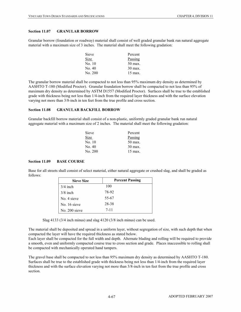
VINEYARD TOWN DESIGN STANDARDS AND SPECIFICATIONS CHAPTER 4, DIVISION 11
ADOPTED FEBRUARY 2007 4-67
Section 11.07 GRANULAR BORROW
Granular borrow (foundation or roadway) material shall consist of well graded granular bank run natural aggregate
material with a maximum size of 3 inches. The material shall meet the following gradation:
Sieve Percent
Size Passing
No. 10 50 max.
No. 40 30 max.
No. 200 15 max.
The granular borrow material shall be compacted to not less than 95% maximum dry density as determined by
AASHTO T-180 (Modified Proctor). Granular foundation borrow shall be compacted to not less than 95% of
maximum dry density as determined by ASTM D1557 (Modified Proctor). Surfaces shall be true to the established
grade with thickness being not less than 1/4-inch from the required layer thickness and with the surface elevation
varying not more than 3/8-inch in ten feet from the true profile and cross section.
Section 11.08 GRANULAR BACKFILL BORROW
Granular backfill borrow material shall consist of a non-plastic, uniformly graded granular bank run natural
aggregate material with a maximum size of 2 inches. The material shall meet the following gradation:
Sieve Percent
Size Passing
No. 10 50 max.
No. 40 30 max.
No. 200 15 max.
Section 11.09 BASE COURSE
Base for all streets shall consist of select material, either natural aggregate or crushed slag, and shall be graded as
follows:
Sieve Size Percent Passing
3/4 inch 100
3/8 inch 78-92
No. 4 sieve 55-67
No. 16 sieve 28-38
No. 200 sieve 7-11
Slag 4133 (3/4 inch minus) and slag 4120 (3/8 inch minus) can be used.
The material shall be deposited and spread in a uniform layer, without segregation of size, with such depth that when
compacted the layer will have the required thickness as stated below.
Each layer shall be compacted for the full width and depth. Alternate blading and rolling will be required to provide
a smooth, even and uniformly compacted course true to cross section and grade. Places inaccessible to rolling shall
be compacted with mechanically operated hand tampers.
The gravel base shall be compacted to not less than 95% maximum dry density as determined by AASHTO T-180.
Surfaces shall be true to the established grade with thickness being not less than 1/4-inch from the required layer
thickness and with the surface elevation varying not more than 3/8-inch in ten feet from the true profile and cross
section.

VINEYARD TOWN DESIGN STANDARDS AND SPECIFICATIONS CHAPTER 4, DIVISION 11
ADOPTED FEBRUARY 2007 4-68
Section 11.10 BITUMINOUS ASPHALT CEMENT PAVEMENT
Over the dry, dust-free compacted base course the Owner/Contractor shall place and compact a bituminous asphalt
cement surface course. The surface course shall consist of a mixture of mineral aggregate and binder. Gradation of
aggregate shall conform to the following:
Sieve Size Percent Passing
3/4 inch 100
3/8 inch 69-91
No. 4 42-58
No. 16 17-31
No. 50 9-21
No. 200 4-8
The Owner/Contractor shall establish a mix gradation, and the amount of bituminous material shall be subject to the
approval of the Public Works Representative/Engineer and shall meet the requirements of the gradation selected.
Regardless of the bituminous content, there shall not be more than 3% voids in the mix.
The bituminous material for the surface course shall be AC-10 penetration asphalt cement conforming to the
requirements of ASTM M20-60.
The bituminous surface course shall be mixed at a mixing plant and spread and compacted on the prepared base in
conformance with the lines and dimensions shown on the Drawings and in accordance with these Specifications.
The bituminous mixtures shall be spread with self-propelled mechanical spreading and conditioning equipment
capable of distributing at least a 12-foot width. The mixture shall be spread and struck off in such a manner that the
finished surface shall result in a uniform smooth surface. The longitudinal joints in succeeding courses shall be
offset at least 6 inches transversely to avoid a vertical joint through more than one course. The maximum compacted
thickness of a single course of asphalt is 4”.
The temperature of the bituminous mix shall be between 270° F and 325° F when placing.
After the mixture has been spread, the surface shall be rolled in longitudinal direction commencing at the outside
edge or lower side and proceeding to the higher side. Each pass of the roller shall overlap the preceding pass at least
one-half the width of the roller. Rolling shall continue until 95% of the laboratory density as determined in
accordance with ASTM Designation D1559 for the bituminous mixture being used has been obtained. Density tests
shall be done following the procedures of ASTM D2950.
Rolling operations shall be conducted in such a manner that shoving or distortion will not develop beneath the roller.
The surface of the pavement, after compaction, shall be uniform and true to the established grade. When tested with
a ten-foot straight edge placed on the surface of the pavement, at any point, the surface shall not deviate more than
one-eighth of an inch from the lower edge of the straight edge. All high and low spots shall be remedied
immediately by removing the wearing course material over the affected areas and replacing it with fresh, hot wearing
course and surface finish material and immediately compacting it to conform with surrounding area.
It is the responsibility of the Owner/Contractor to control traffic. All traffic shall be kept off the completed surface
for a minimum period of 24 hours.
No bituminous surface course shall be placed when the temperature of the air or roadbed is 50° F or below, during
rainy weather, when the base is wet, or during other unfavorable weather conditions as determined by the Public
Works Representative/Engineer. The air temperature shall be measured in the shade.

VINEYARD TOWN DESIGN STANDARDS AND SPECIFICATIONS CHAPTER 4, DIVISION 11
ADOPTED FEBRUARY 2007 4-69
Section 11.11 ADJUSTING MANHOLES AND VALVE BOXES TO FINAL GRADE
This section covers the requirements for adjusting manholes and valves to final grade. The adjustment shall be made
with cast-iron ring inserts, concrete grade rings or cast-in-place concrete rings or squares. Cast-in-place concrete
rings or squares shall be constructed after the asphalt surface has been placed.
When concrete rings are used the concrete shall conform to the requirements of Division 8. Concrete shall be Class
AA(AE). The concrete mix shall be one part cement to two parts sand or Kent Seal.
Manholes and valves in asphalt surfaces shall have the cast iron ring and cover constructed such that the cast iron
ring is one sixteenth inch (1/16th") lower than the finished surface. Manhole rings shall be set to the grade and slope
of the road – shim and grout ring into place.
Where manholes are to be raised this is be accomplished by removing the cover and frame and raising the manhole
to proper elevation with concrete.
Rings and covers shall be protected during backfilling and compaction of the soil and during the placing or replacing
of road surfaces. Any ring or cover loosened from the manhole section shall be resent in cement mortar and any ring
or cover damaged or broken shall be replaced by the Owner/Contractor at its expense.
Manhole rings and covers and valve boxes shall have concrete collars around them. Existing or new asphalt around
the manhole ring and cover or valve box shall be jack hammered out, road base around the manhole ring and cover
or valve box shall be recompacted, and the concrete collar shall be placed.

VINEYARD TOWN DESIGN STANDARDS AND SPECIFICATIONS CHAPTER 4, DIVISION 11
ADOPTED FEBRUARY 2007 4-70
Section 11.12 PLANT MIX SEAL COAT
On all streets in excess of 8%, or at locations specified by the Public Works Representative/Engineer, place a 1-inch
layer of plant mix seal coat on the asphalt surface. Due to gradually varying street slopes and the desire to maintain
surface consistency, the Public Works Representative/Engineer may specify the locations requiring the plan mix seal
coat differently than stipulated by the 8% slope requirement.
Where no plant mix seal coat is called for in a pavement design, reduce the specified bituminous asphalt cement
pavement thickness by ½ inch, and replace it with the 1-inch layer of plant mix seal coat.
The plant mix seal coat shall consist of clean, hard fragments of 100 percent crushed virgin stone, gravel, or slag.
Gradation of aggregate shall conform to the following:
Sieve Size Percent Passing
1/2 inch 100
3/8 inch 90-100
No. 4 34-45
No. 8 0-10
No. 200 0-3
The Owner/Contractor shall establish a mix gradation, and the amount of bituminous material shall be subject to the
approval of the Public Works Representative/Engineer and shall meet the requirements of the gradation selected.
The bituminous material shall be AC-10 penetration asphalt cement conforming to the requirements of AASHTO M
225, Table 2 and AASHTO T 40.
The plant mix seal coat shall be spread with self-propelled mechanical spreading and conditioning equipment capable of
distributing at least a 12-foot width. The mixture shall be spread and struck off in such a manner that the finished
surface shall result in a uniform smooth surface. The longitudinal joints shall be offset at least 6 inches transversely
from the underlying joints.
Place plant mix seal coat only when the air temperature in the shade and the pavement surface temperature is above 60°
F and rising. Do not place plant mix seal coat during rain, when the pavement surface is wet, or during other adverse
weather conditions, as determined by the Public Works Representative/Engineer.
After the mixture has been spread, the surface shall be rolled in longitudinal direction commencing at the outside edge or
lower side and proceeding to the higher side. Each pass of the roller shall overlap the preceding pass at least one-half
the width of the roller. Rolling operations shall be conducted in such a manner that shoving or distortion will not
develop beneath the roller. Rolling shall continue until 95% of the laboratory density as determined in accordance with
ASTM Designation D1559 has been obtained. Density tests shall be done following the procedures of ASTM D2950.
The surface of the pavement, after compaction, shall be uniform and true to the established grade. When tested with a
ten-foot straight edge placed on the surface of the pavement, at any point, the surface shall not deviate more than one-
eighth of an inch from the lower edge of the straight edge. All high and low spots shall be remedied immediately by
removing the plant mix seal coat over the affected areas and replacing it with fresh, hot plant mix seal coat and
immediately compacting it to conform with surrounding area.

VINEYARD TOWN DESIGN STANDARDS AND SPECIFICATIONS CHAPTER 4, DIVISION 12
ADOPTED FEBRUARY 2007 4-71
DIVISION 12
CONCRETE CURB AND GUTTER AND SIDEWALK
Section 12.01 GENERAL
This section covers installation of curb and gutter, sidewalk, combination of curb, gutter and sidewalk, cross gutter,
drive approaches handicap ramps and curb returns. All improvements shall be constructed to the dimensions and
thickness shown on the Standard Drawings.
Section 12.02 CONCRETE
Concrete shall be Class AA(AE) and shall meet all of the requirements of Division 8, Portland Cement Concrete.
Under no condition shall the water cement ratio exceed 0.53.
Section 12.03 GRADE
After construction, gutters shall be checked by flowing water. The Public Works Representative/Engineer shall be
present during the flow test. Any high spots or depressions (which exceed 0.02 feet) shall be repaired by removing
concrete and replacing to the correct grade. Puddling shall not flow from flow line past lip of gutter. (Minimum flow
line grade shall be 0.5 percent.)
Section 12.04 FORMS
All forms shall be steel, except at curves with a radius smaller than 200 feet. They shall be of a size to match the
sections shown on the Drawings. Forms shall be held firmly in place with stakes or other approved means and shall
be true to line and grade.
All forms shall be clean and coated with a light oil to prevent the concrete from adhering to them. Clamps, spreaders
and braces shall be used where required to insure rigidity in the forms.
Forms shall not vary from vertical grade by more than 0.02 feet and from horizontal alignment by more than 0.05
feet. All forms shall have smooth even lines in both the horizontal and vertical plane.
Forms for curved sections shall be so constructed and placed that the finish surface of walls and edge of sidewalks,
curbs and gutters will not deviate from the arc of the curve.
Section 12.05 SUBGRADE PREPARATION
The Owner/Contractor shall grade to the line and grade approved by the Town. No concrete shall be placed without
approved cut sheets. The sub-grade shall be properly shaped to conform with the cross section shown on the
Standard Drawings, graded and compacted. Compaction shall meet the requirements of Division 7 Earthwork.
All excess material excavated by the Owner/Contractor shall be removed from the site. Removal of the excavated
material shall be done before or immediately after the concrete is placed. The Owner/Contractor shall maintain
adequate barricades and other devices to protect the public until excavated material is removed.
Placement of concrete on unsuitable materials shall not be permitted. The subgrade surface shall have a 4-inch
roadbase foundation as shown on the Standard Drawings. Immediately prior to the placing of concrete, the subgrade
shall be compacted using a mechanical foot compactor, with compaction being at least 95% of the maximum dry
density as determined by AASHTO T-180 (Modified Proctor).

VINEYARD TOWN DESIGN STANDARDS AND SPECIFICATIONS CHAPTER 4, DIVISION 12
ADOPTED FEBRUARY 2007 4-72
Section 12.06 CONSTRUCTION OF CURB, GUTTER AND SIDEWALK
Concrete curb, gutter and sidewalk may be constructed by first constructing the curb and gutter and then constructing
the sidewalk behind it. If this method is used the joint between the back of curb and front edge of sidewalk shall be
sealed. The curb and gutter may be placed using stationary forms or the slip method of forming.
Monolithic curb, gutter and sidewalk may be constructed. Stationary forms can be used to place combination curb,
gutter and sidewalk. The slip form method can be used if it can be demonstrated that the tolerances specified herein
can be met.
Curb and gutter to be installed with bituminous asphalt cement pavement shall have contraction joints placed every
10 feet by use of 1/8-inch steel template of the exact cross section of the curb and gutter. Remove the templates as
the concrete takes initial set. Cut the joint 1-1/2 inches deep when using the slip form method to place the concrete.
Use 1/2-inch thick, pre-molded, expansion joint filler at curb and gutter radii, where the curb and gutter abuts a solid
object and at intervals not to exceed 50 feet, unless otherwise specified by the Public Works
Representative/Engineer.
Joints in sidewalk, when placed separately and adjacent to the curb shall match the contraction and expansion joints
in the curb and gutter as well as where the sidewalk abuts a solid object. Sidewalks not placed adjacent the curb
shall have contraction joints at 10-foot intervals. The joints shall be approximately 3/16 inch wide and
approximately one-half of the total slab thickness in depth. Expansion joints shall be 1/2-inch thick, shall be placed
every 50 feet, adjoins existing sidewalks, or abuts a solid object.
Material for 1/2-inch expansion joints shall be as specified in AASHTO M-153 and AASHTO M-213, and shall be
installed with its top approximately 1/4-inch below the concrete surface.
After the concrete placed for a sidewalk has been brought to the established grade and screeded, it shall be float
finished, edged and then given a light broom finish. In no case shall dry cement or a mixture of dry cement and sand
be sprinkled on the surface to absorb moisture or hasten hardening. Surface edges of all slabs shall be rounded to a
radius of 1/2 inch.
After concrete has been placed in curb and gutter forms, it shall be consolidated so as to insure a thorough mixture,
eliminate air pockets, and create uniform, smooth sides. As the concrete takes its initial set the forms shall be
removed and all exposed surfaces shall be float finished, edged and broomed lightly. The curb and gutter shall be
constructed to the dimensions shown in the Standard Drawings.
The top and face of the curb and also the top of the apron on combination curb and gutter must be finished true to
line and grade and without any noticeable irregularities of surface. No portion of the surface or face of the curb and
gutter shall depart more than 1/4 inch from a straight edge ten feet in length, placed on the curb parallel to the street
center line nor shall any part of the exposed surface present a wavy appearance.
Section 12.07 CONCRETE CURB WALL
Concrete curb wall shall be Class AA(AE) and shall meet all of the requirements of Division 8, Portland Cement
Concrete.
Reinforcing steel shall meet the requirements of Division 9, Reinforcing Steel.
Excavation for and backfill around the curb walls shall meet all the requirements of Division 7, Earthwork.
The curb walls shall be constructed to the dimensions and grades shown on the Standard Drawings or improvement
drawings or as determined by the Public Works Representative/Engineer.

VINEYARD TOWN DESIGN STANDARDS AND SPECIFICATIONS CHAPTER 4, DIVISION 12
ADOPTED FEBRUARY 2007 4-73
Section 12.08 5-INCH CONCRETE DRIVE APPROACH
The concrete to be used for the drive approach shall be Class AA(AE) and shall meet the requirements of Division 8,
Portland Cement Concrete.
The driveways shall be a minimum of 5-inch thick. They shall be constructed to the dimensions shown on the
Standard Drawings. The concrete shall be finished as described above for sidewalks.
The driveways shall have a compacted 4-inch untreated base course under them.
Section 12.09 ACCESSIBILITY STANDARDS IN PUBLIC RIGHTS-OF-WAY
This section sets guidelines for accessibility in public rights-of-way. These guidelines are to be applied during the
design, construction, and alteration of improvements in public rights-of-way. These guidelines are to be followed
insomuch as they are technically feasible.
The construction of curb ramps and drive approaches shall conform to the Standard Drawings.
The following definitions apply:
a) The pedestrian access route is an accessible corridor for pedestrian use within the public right-of-way.
b) Pedestrian crossings are those locations in which pedestrians cross streets.
c) A ramp is a portion of the pedestrian access route that makes a vertical transition between two flatter
surfaces. It is sloped in the direction of travel. It does not include the side flares that exist on a
perpendicular curb ramp.
d) The side flare is the portion of a perpendicular curb ramp that transitions between the plane of the ramp
surface and the plane of the flatter adjacent sidewalk.
e) The term perpendicular curb ramps refers to all features associated with a ramp whose running slope is
perpendicular to the curb line.
f) The term parallel curb ramps refers to all features associated with a ramp whose running slope is in the
direction of sidewalk travel.
g) Blended transitions are locations along the pedestrian access route in which the street and the sidewalk are
at the same level.
h) Detectable warning is a surface feature built in or applied to walking surfaces or other elements to warn of
hazards on a circulation path.
The pedestrian access route shall not be less than 4 feet wide, not including the curb, and shall have a cross slope of
not more than 2%.
Concrete surfaces shall have a broom finish to increase slip resistance.
Sub-section A. Sidewalks:
The cross slope shall not exceed 2%.
Changes in level/elevation (vertical rises between adjacent surfaces) shall meet the following requirements:
1) Differences of up to ¼ inches can remain without beveling.

VINEYARD TOWN DESIGN STANDARDS AND SPECIFICATIONS CHAPTER 4, DIVISION 12
ADOPTED FEBRUARY 2007 4-74
2) Differences of over ¼ inch but no more than ½ inch must be beveled with a maximum grade of 2:1
(50%).
3) Differences of over ½ inch must be removed or a ramp must be created having a maximum grade of
12:1 (8.33%).
Sub-section B. Curb Ramps:
Curb ramps shall be provided wherever a pedestrian access route crosses a curb.
The ramp grade shall not exceed 12:1 (8.33%).
The cross slope of the ramp shall not exceed 50:1 (2%), except that on perpendicular curb ramps at
midblock crossings, the cross slope may match the slope of the adjacent street.
The minimum ramp width shall be 48 inches.
No lip shall exist at the bottom of curb ramps.
Sub-section C. Landings:
A landing shall exist at the top of curb ramps. The landing shall not have a slope in excess of 2% in any
direction, and shall be a minimum of 48 inches by 48 inches in size. Parallel curb ramps and blended
transitions shall have a landing at the bottom of the ramp (still in the sidewalk, not in the street) meeting the
same criteria.
At the foot of diagonal curb ramps (ramps located in the curb return, whose running slope is directed
diagonally into the intersection), a 48-inch by 48-inch landing of clear space must exist, beyond the curb
line, entirely contained within the crosswalks, and outside of the vehicular travel lanes.
Sub-section D. Side Flares:
The slope of side flares on perpendicular curb ramps shall not exceed 10:1 (10%).
If it is not technically feasible to achieve a 4-foot landing (measured in the direction of the running slope of
the ramp) at the top of a perpendicular curb ramp, the landing may be reduced to 3 feet, in which case the
slope of the side flares shall not exceed 12:1 (8.33%).
Sub-section E. Detectable Warnings:
Detectable warning panels shall be placed at ramps and other locations in which the pedestrian access route
crosses streets. They are intended to warn visually-impaired people of potential hazards by indicating the
transition from sidewalk to street.
The detectable warning panels shall be cast-in-place and shall have the following characteristics:
1) Polymer composite material of homogeneous integral safety yellow color (UV stable)
2) Skid and abrasion resistant
3) Non-glare finish
They shall consist of truncated domes aligned in a square grid pattern having the following characteristics:
1) Base diameter of 0.9 inch – 1.4 inch
2) Top diameter of 50%-60% of base diameter
3) Height of 0.2 inch
4) Center-to-center spacing of 1.6 inch – 2.4 inch
VINEYARD TOWN DESIGN STANDARDS AND SPECIFICATIONS CHAPTER 4, DIVISION 12
ADOPTED FEBRUARY 2007 4-75
The detectible warning shall be 2 feet deep (measured in the direction of pedestrian travel). They shall run
across the full width of ramps or blended transitions. They should be set back 6” to 8” from the flowline of
the gutter.
The detectable warning panel shall be installed so that it is flush (at the base of the truncated domes) with
the adjacent concrete.
Sub-section F. Pedestrian Crossings:
Where crosswalks are marked, they shall be at least 8 feet wide.
The foot of a curb ramp shall be wholly contained within the crosswalk markings.
The cross slope (measured perpendicular to the direction of pedestrian travel) of marked or unmarked
crosswalks is limited to 2%, except at mid-block crossings.
The counterslope of the gutter or street surface at the bottom of a ramp or blended transition (measured in
the direction of pedestrian travel) shall not exceed 5%.
The maximum running slope (measured in the direction of travel) for crosswalks is 5%.
Section 12.10 LANDSCAPE RESTORATION
Areas of new construction that cover or disturb existing landscaped areas with fills and cuts or areas disturbed by
construction of retaining walls shall have the landscape restored. Areas that have lawn or flower beds shall be
restored including sprinkling systems that might be damaged or relocated because of construction. Lawn covered or
removed shall be replaced by sod.
The topsoil shall be fertile, sandy loam topsoil, obtained from well-drained areas. It shall be without admixture of
subsoil or slag and shall be free of stones, lumps, sticks, plants or their roots, toxic substances or other extraneous
matter that may be harmful to plant growth and would interfere with future maintenance. Topsoil pH range shall be
5.3 to 6.0.

VINEYARD TOWN DESIGN STANDARDS AND SPECIFICATIONS CHAPTER 4, DIVISION 13
ADOPTED FEBRUARY 2007 4-76
DIVISION 13
STORM DRAINS
Section 13.01 GENERAL
This section covers installation of storm drainpipe, manholes, and curb face inlet boxes. All improvements shall be
constructed to the dimension and thickness shown on the Standard Drawings.
Section 13.02 PIPE INSTALLATION
Installation of pipe shall be in an open trench unless otherwise shown. Trench and backfill shall meet the
requirements of Division 2, Trench Excavation and Backfill.
Section 13.03 PIPE
Pipe and pipe laying shall meet the requirements of Division 4, Concrete Pipe, Division 4A, PVC Plastic Pipe,
Division 4B, Polyethylene Corrugated Pipe, Division 4C, Polyethylene Corrugated Pipe with Water Tight Joints.
Pipe shall be laid with the bells up grade.
Section 13.04 MANHOLES
Manholes shall meet the requirements of Division 5, Manholes. Where the size of the storm drain does not permit
use of manholes, precast or cast-in-place reinforced concrete boxes shall be used. Concrete used in precast or cast-
in-place boxes shall be Class AA(AE).
Section 13.05 CONCRETE
Concrete shall meet the requirements of Division 8, Portland Cement Concrete.
Section 13.06 REINFORCING STEEL
Reinforcing steel shall meet the requirements of Division 9, Reinforcing Steel.
Section 13.07 STORM DRAIN INLET BOXES
The concrete to be used for the storm drain inlet boxes shall be Class AA(AE). The boxes shall be built to the
dimensions and reinforced as shown on the Standard Drawings. The boxes may be precast or cast-in-place.
Excavation and backfill of the boxes shall meet the requirements of Division 7, Earthwork.
The storm drain inlet grate and frame shall be a D & L Supply I-3518 single unit with curb box with type "V" grate
or equal. Grates and frames are to be dipped in cold tar epoxy following fabrication.
Section 13.08 PIPE CONNECTING INLET BOXES TO EXISTING STORM DRAINS
The pipe to be used for connecting a new inlet box to an existing storm drain shall be of the same type of pipe as the
existing pipe to which it is being connected. Where possible such connections shall be made by installation of a
manhole. The Public Works Representative/Engineer shall approve connection locations and methods.
Connections to concrete pipe shall be by coring a hole in the pipe and then grouting the connecting pipe to the
concrete pipe. Connections to PVC or HDPE pipe shall be as per manufacture's recommendations. These
recommendations will be reviewed with the Public Works Representative/Engineer prior to construction.
VINEYARD TOWN DESIGN STANDARDS AND SPECIFICATIONS CHAPTER 4, DIVISION 14
ADOPTED FEBRUARY 2007 4-77
DIVISION 14
UTAH DEPARTMENT OF TRANSPORTATION
RIGHTS-OF-WAY
Section 14.01 GENERAL
Work to be performed within UDOT rights-of-way shall be done in accordance with "SPECIFICATIONS FOR
EXCAVATION ON DEPARTMENT OF TRANSPORTATION RIGHT-OF-WAY", latest revision. The
Owner/Contractor shall be responsible to obtain all necessary permits and meet any bond requirements imposed by that
agency.
Section 14.02 UTILITY LINE AGREEMENT
The improvements to be placed along or across UDOT rights-of-way are subject to the conditions of Utility Line
Agreements between the UTAH DEPARTMENT OF TRANSPORTATION and VINEYARD TOWN. The
Owner/Contractor is bound by all conditions of the Agreement. The Owner shall be responsible for completing the
Utility Line Agreement and furnishing the necessary Drawings and other information, including meeting with UDOT to
insure requirements are met, required by UDOT. The Owner shall then submit the completed agreement to the
Town for signature and forwarding to UDOT. The Owner/Contractor shall not proceed with any work in a UDOT right-
of-way until it has obtained a permit from UDOT, posted the required bond (if one is required) and provided any other
information, such as traffic control plans, required by UDOT.
Section 14.03 INSPECTION FEES
The Owner/Contractor will pay UDOT fees for any UDOT inspectors.

VINEYARD TOWN DESIGN STANDARDS AND SPECIFICATIONS CHAPTER 4, DIVISION 15
ADOPTED FEBRUARY 2007 4-78
DIVISION 15
CASINGS
Section 15.01 GENERAL
This division defines the materials and construction requirements for steel casings under canals, railroad tracks,
highways and Interstates. All construction operations shall be subject to the approval of the canal, Railroad
Company or UDOT whose facility is being crossed. The Owner/Contractor shall make application to and secure
permission from the canal, Railroad Company or UDOT before commencing work within the right-of-way. The
Owner/Contractor shall provide all insurance and the services of all watchmen and flagmen required by the Railroad
Company or UDOT. The Owner/Contractor will pay the Railroad Company and UDOT for their inspection services.
Section 15.02 MATERIALS
The pipe shall be welded steel pipe conforming to ASTM Designation A139, Grade A. Pipe wall thickness shall be
as shown below, unless otherwise shown on the Drawings.
Casing Diameter Minimum Wall Thickness
12” or less .2500” 1/4”
Over 12” – 18” .3125” 5/16”
Over 18” – 22” .3750” 3/8”
Over 22” – 28” .4375” 7/16”
Over 28” – 34” .5000” 1/2”
Over 34” – 42” .5625” 9/16”
Over 42” – 48” .6250” 5/8”
Section 15.03 CONSTRUCTION METHODS
The steel pipe casing shall be jacked under the railroad tracks, highway or Interstate using methods submitted to the
Public Works Representative/Engineer for review by the Public Works Representative/Engineer. Circular pipe joints
shall be field welded as the jacking process progresses. The pipe interior shall be completely excavated and cleaned
prior to installation of the carrier pipe.
Steel pipe casing shall be installed by open cut under canals. These installations shall be as per details approved by
the canal company.
All required approach trenches or working pits shall be excavated and shored as defined in Division 2, Trench
Excavation and Backfill. Provisions shall be made for a drain sump in one corner of the working pit to allow for the
accumulation and pumping of seepage water, if ground water is expected to be encountered.
Section 15.04 LINE AND GRADE
Casings shall be installed accurately to the line and grade shown on the Drawings. Casings shall be installed to grade
with sufficient accuracy to permit installation of the carrier pipe to the design grade shown on the Drawings or to the
cover depth required. The Owner’s Public Works Representative/Engineer will provide base lines and bench marks
at each casing location. Instrument checks of the line and grade shall be made by the Owner/Contractor at intervals
sufficient to maintain the casing on line and grade.
Section 15.05 CARRIER PIPE INSTALLATION THROUGH CASINGS
The carrier pipe shall be installed to the grade shown on the Drawings. Casing spacers shall be fastened to the
carrier pipe as per the manufacturer's recommendations. As a minimum, spacers for ductile iron or PVC pipe shall
be installed within one foot on each side of the bell and one in the center of the pipe when 18' or 20' lengths are
used.

VINEYARD TOWN DESIGN STANDARDS AND SPECIFICATIONS CHAPTER 4, DIVISION 15
ADOPTED FEBRUARY 2007 4-79
Following installation of the carrier pipe the annular space between the inside of the casing and the outside of the
carrier pipe shall be blown full of sand. The sanding operation shall be carried out such that sand is placed in the
center of the casing first and the annular space filled as the placing pipe is withdrawn. The Developer/Contractor
shall not be allowed to wash sand in from the end of the casing.
Section 15.06 CASING SPACERS
Factory manufactured casing spacers shall be installed on all carrier pipes passing through a casing pipe. Wooden skids
will not be allowed as an alternative.
Casing spacer shall be a two-piece shell made from T-304 stainless steel of a minimum 14 gauge thickness. Each shell
section shall be lined with a 0.090" thick material that prevents slippage. Bearing surfaces (runners) shall be ultra high
molecular weight polyethylene (UHMW) or similar material to provide abrasion resistance and a low coefficient of
friction (0.12). The runners shall be attached to support structures (risers) at appropriate positions to properly support
the carrier within the casing and to ease installation. Risers shall be made of 10 gauge T-304 stainless steel. Bottom
risers 6" and over in height shall be reinforced.
Standard positioning within the casing pipe shall be sized such that the height of the risers and runners are to provide not
less than three-fourths inch between the casing pipe and the outside diameter of the bell of the carrier pipe.
Centered & Restrained positioning within the casing pipe shall be sized such that the height of the risers and runners are
to center the carrier pipe in the casing pipe with a top clearance of one-half inch minimum.
Restrained positioning within the casing pipe shall be sized such that the height of the risers and runners are to provide
not less than three-fourths inch between the casing pipe and the outside diameter of the bell and a top clearance of one-
half inch minimum.
All welds and metal surfaces shall be chemically passivated and all hardware is to be stainless steel.
Casing spacers may be manufactured by Cascade Waterworks Manufacturing Company, Advanced Products Systems or
another manufacturer that can produce an approved equal. Due to the numerous application possibilities, consult
manufacturer for spacing requirements and model number.

VINEYARD TOWN DESIGN STANDARDS AND SPECIFICATIONS CHAPTER 4, DIVISION 16
ADOPTED FEBRUARY 2007 4-80
DIVISION 16
FLOWABLE FILL
Section 16.01 GENERAL
This division defines the materials and procedures for placing flowable fill.
Flowable fill is used as backfill in certain trench applications such as backfilling around the pipe work of a drop
manhole, or backfilling trenches in State Highways.
Section 16.02 MIX DESIGN
The following requirements shall be met:
a) The 28 day compressive strength shall be between 50 and 150 psi.
b) Use at least 50 pounds of Portland Cement Type I or II per cubic yard of flowable fill.
c) Use at least 300 pounds of Fly Ash per cubic yard of flowable fill. Supply Fly Ash as specified except that
the loss on ignition must be 3 percent or less.
d) The slump shall be between 6 inches and 10 inches.
e) Use natural sand meeting the following gradation:
Passing ¾-inch sieve: 100%
Passing No. 100 sieve: 0%-10%
Section 16.03 CONSTRUCTION METHODS
Discharge flowable fill from the ready mix truck by any reasonable means into the trench to be filled. Place the fill
up to the bottom of the surface course and finish to provide a uniform surface.
Section 16.04 CONSTRUCTION IN UDOT RIGHTS OF WAY
When used in State Highways, materials and procedures shall be in conformance with the requirements of Section
03575 Flowable Fill of the current Utah Department of Transportation Standard Specifications for Road and Bridge
Construction (available on the Internet at the UDOT web site). In locations where its use would be impractical,
UDOT may not require flowable fill.

VINEYARD TOWN DESIGN STANDARDS AND SPECIFICATIONS CHAPTER 4, DIVISION 17
ADOPTED FEBRUARY 2007 4-81
DIVISION 17
CONDUIT
Section 17.01 GENERAL:
This Division covers furnishing and installing utility and telecommunications conduit.
Section 17.02 UTILITY CONDUIT:
Owners shall be responsible to install utility conduits for placement of public utilities.
Sub-section A. Materials:
The conduit shall be of the material specified by each utility company.
Sub-section B. Location:
Conduits shall be installed at locations established by utility company engineers and approved by the Town.
Excavation shall be at depth and standards of utility companies. Conduits shall have bends attached to
each end and placed vertically out of the ground for location verification. Conduits within street rights-of-
way shall have a minimum of 18” cover below finished street grade.
Sub-section C. Magnetic Locator Tape:
All utility conduits shall include a 3” magnetic locator tape installed in the pipeline trench approximately
12” below the ground surface, with appropriate cautionary wording printing on the tape to identify the type
of utility present.
Section 17.03 TELECOMMUNICATIONS CONDUIT:
Sub-section A. Telecommunications Conduit in New Developments:
a) Materials: Install two orange 1¼” diameter SDR-11 HDPE conduits meeting ASTM 3035.
b) Location: In new developments telecommunications conduit shall be installed to serve all lots, and
shall be laid in the same location as the telephone lines. The conduit shall be laid at a minimum
depth of cover of 24”. In the immediate vicinity of service boxes the conduit shall be laid at a
shallower depth of cover of 15”, so that they are directly below the bottom of the service box, so
that the conduit is visible when the cover of the box is removed. The conduit is not to be cut at
service boxes, but it to be laid continuously under the boxes.
c) Boxes: Service boxes shall be placed at every other property line, so that service can be provided
to two lots from each box. The top of the boxes shall be placed flush with the finished ground
surface. They shall be green 15” deep, 14” x 20” HDPE Newbasis Splice/Valve Box S1420 with
cover assembly, including stainless steel lock bolt (part no. SGA142015Y000). The label
“TELECOM” shall be imprinted on the cover.
Sub-section B. Telecommunications Conduit for Future Use (Other Than in New Developments):
d) Materials: Install one orange 4” schedule 40 PVC conduit rated at 194° F meeting NEMA TC-2,
NEMA TC-3, UL listed.
e) Location: Conduits shall be installed across streets from right-of-way line to right-of-way line.
Crossing shall be at intersections (generally at about the end of the curb return) and at
approximately 400’ intervals. Locations shall be shown on the improvement plans and approved
by the Town. In order to mark the location of conduits, a “C” shall be stamped in the top of curb

VINEYARD TOWN DESIGN STANDARDS AND SPECIFICATIONS CHAPTER 4, DIVISION 17
ADOPTED FEBRUARY 2007 4-82
(before it is cured) at locations where the conduit crosses the curb and gutter. Conduit shall be laid
36” below the finished road grade, measured to the top of the conduit.
Sub-section C. Joints & Fittings:
The contractor shall provide all materials used in the installation of conduits, such as bends, adapters,
couplings, glue, plugs and fittings, to meet or exceed all of the recommendations of the conduit
manufacturer for suitable installation.
Sub-section D. Caution Tape:
Telecommunications conduit shall include a 3” caution tape installed in the pipeline trench approximately
12” below the ground surface, with the words “CAUTION: BURIED FIBER OPTIC CABLE” printed on
it.
Sub-section E. Tracer Wire:
A twelve (12) gauge solid THHN tracer wire shall be installed according to NESC standards inside one
conduit of every bundle of conduit that is laid together. If there is only a single conduit, place the tracer
wire in it. At least four feet of slack tracer wire shall be present at every location where the conduit is
accessible from the surface.
Section 17.04 INSTALLATION:
Sub-section A. Cutting:
Cutting of conduit for closure pieces or for other reasons shall be done in a neat and workmanlike manner
by a method recommended by the manufacturer.
Sub-section B. Dewatering of Trench:
Where water is encountered in the trench, it shall be removed during conduit laying operations and the
trench so maintained until the ends of the conduits are sealed. See "Control of Groundwater" in Division 2
Trench Excavation and Backfill.
Sub-section C. Laying of Conduit:
The conduit shall be inspected for defects before installation. Any defects shall be repaired or the conduit
shall be replaced, whichever is deemed necessary by the Engineer.
All conduits shall be laid and maintained to the required lines and grades. The Contractor shall be
responsible to install the conduit line to the alignment set by the Engineer or as shown on the Drawings.
The Contractor shall take the necessary precautions such that foreign materials do not enter into the conduit.
No debris, tools, or other materials shall be placed in the conduit during laying operations. When laying of
conduit is not in progress, the conduit shall be closed by a watertight plug.
Maximum vertical or horizontal deflections of conduit are not to exceed a ratio of 10:1 along its length (e.g.
no more than 4”deflection per 40” length.)
Install all conduit bends to have a radius that is:
1. Not less than 10 times the inside diameter of the conduit.
2. Not less than the minimum bend radius called out on the plans.
At no time shall the conduit be deformed to make a bend.
The minimum separation between conduits shall be 1.5”.

VINEYARD TOWN DESIGN STANDARDS AND SPECIFICATIONS CHAPTER 4, DIVISION 17
ADOPTED FEBRUARY 2007 4-83
The minimum separation between the conduit and trench wall shall be 1.5”.
Sub-section D. Bedding:
All conduits shall be protected from lateral displacement and possible damage resulting from impact or
unbalanced loading during backfilling operations by being adequately bedding.
In the event trench materials are not, in the judgment of the Engineer, satisfactory for conduit bedding,
imported granular bedding will be required. See Division 2 of these specifications.

VINEYARD TOWN DESIGN STANDARDS AND SPECIFICATIONS CHAPTER 4, DIVISION 18
ADOPTED FEBRUARY 2007 4-84
DIVISION 18
STREET LIGHTING
Section 18.01 GENERAL
This division describes the design of street lights to be used along roads in commercial zones.
Section 18.02 MATERIALS
In order to achieve a uniform design, street lights shall be Washington Postlite (or equivalent). The Washington
Postlite luminaire is an acorn style, with finial, decorative ribs, band and medallions (see Holophane US-1454).
The post shall be Holophane Salem series (or equivalent), black, all aluminum, one-piece construction, with a classic
fluted base design. The shaft shall be 16’ tall, 5” diameter fluted, with a 13” square base, with a square anchor bolt
cover. A 24” long bolt-on banner arm shall be mounted 14’ above the base of the post. A bolt-on eyebolt shall be
mounted 10’ above the base of the post. A weatherproof receptacle shall be mounted 15’-6” above the base of the
post, opposite the banner arm and eyebolt. See Holophane US-1668.
The street lights shall have a nominal total height of 19’-9”.
The street light shall be Holophane catalog number S16F5/13-CA/BK-LAB-BA24B/1/BO-EB/BO-CA/BK-
RS/GFI/WPC-WA250MH12B4B6PR-25LEADS or equivalent.
Section 18.03 SPACING
Streetlights shall be installed along street frontage at 200-foot intervals.