Embed Size (px)
Citation preview

STANDARD SPECIFICATIONS CONSTRUCTION AND MATERIALS METRIC UNITS
Volume II: Structures and Incidental Construction Sections 550 - 699 OFFICE OF ENGINEERING
JANUARY 2, 2002
NEW YORK STATE DEPARTMENT OF TRANSPORTATION George E. Pataki, Governor Joseph Boardman, Commissioner
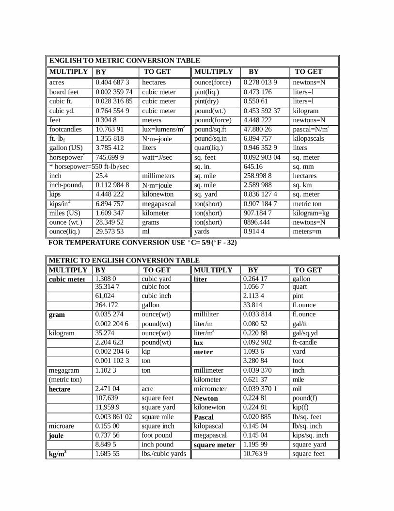
ENGLISH TO METRIC CONVERSION TABLE
MULTIPLY BY TO GET MULTIPLY BY TO GET acres 0.404 687 3 hectares ounce(force) 0.278 013 9 newtons=N board feet 0.002 359 74 cubic meter pint(liq.) 0.473 176 liters=l cubic ft. 0.028 316 85 cubic meter pint(dry) 0.550 61 liters=l cubic yd. 0.764 554 9 cubic meter pound(wt.) 0.453 592 37 kilogram feet 0.304 8 meters pound(force) 4.448 222 newtons=N footcandles 10.763 91 lux=lumens/m2 pound/sq.ft 47.880 26 pascal=N/m2 ft.-lbf 1.355 818 N@m=joule pound/sq.in 6.894 757 kilopascals gallon (US) 3.785 412 liters quart(liq.) 0.946 352 9 liters horsepower* 745.699 9 watt=J/sec sq. feet 0.092 903 04 sq. meter * horsepower=550 ft-lbf/sec sq. in. 645.16 sq. mm inch 25.4 millimeters sq. mile 258.998 8 hectares inch-poundf 0.112 984 8 N@m=joule sq. mile 2.589 988 sq. km kips 4.448 222 kilonewton sq. yard 0.836 127 4 sq. meter kips/in2 6.894 757 megapascal ton(short) 0.907 184 7 metric ton miles (US) 1.609 347 kilometer ton(short) 907.184 7 kilogram=kg ounce (wt.) 28.349 52 grams ton(short) 8896.444 newtons=N ounce(liq.) 29.573 53 ml yards 0.914 4 meters=m
FOR TEMPERATURE CONVERSION USE EC= 5/9(EF - 32) METRIC TO ENGLISH CONVERSION TABLE MULTIPLY BY TO GET MULTIPLY BY TO GET cubic meter 1.308 0 cubic yard liter 0.264 17 gallon 35.314 7 cubic foot 1.056 7 quart 61,024 cubic inch 2.113 4 pint 264.172 gallon 33.814 fl.ounce gram 0.035 274 ounce(wt) milliliter 0.033 814 fl.ounce 0.002 204 6 pound(wt) liter/m 0.080 52 gal/ft kilogram 35.274 ounce(wt) liter/m2 0.220 88 gal/sq.yd 2.204 623 pound(wt) lux 0.092 902 ft-candle 0.002 204 6 kip meter 1.093 6 yard 0.001 102 3 ton 3.280 84 foot megagram 1.102 3 ton millimeter 0.039 370 inch (metric ton) kilometer 0.621 37 mile hectare 2.471 04 acre micrometer 0.039 370 1 mil 107,639 square feet Newton 0.224 81 pound(f) 11,959.9 square yard kilonewton 0.224 81 kip(f) 0.003 861 02 square mile Pascal 0.020 885 lb/sq. feet microare 0.155 00 square inch kilopascal 0.145 04 lb/sq. inch joule 0.737 56 foot pound megapascal 0.145 04 kips/sq. inch 8.849 5 inch pound square meter 1.195 99 square yard kg/m3 1.685 55 lbs./cubic yards
yard 10.763 9 square feet

METRIC TO ENGLISH CONVERSION TABLE 0.062 428 lbs./cubic feet square 0.001 55 square inch km/hr 0.621 37 miles per hour square
kilometer 0.386 102 square mile
watt (J/second)
0.001 341 horsepower 0.737 56 ft-lb/second
FOR TEMPERATURE CONVERSION USE EF = 9/5 EC + 32

STANDARD SPECIFICATIONS VOLUME II OF III JANUARY 2, 2002 STATE OF NEW YORK DEPARTMENT OF TRANSPORTATION
Additional copies of this book, and many other Department publications, may be obtained from: State of New York Department of Transportation Plan and Publication Sales 1220 Washington Avenue Albany, New York 12232 - 0204 Telephone (518) 457-2124 www.dot.state.ny.us

Section 550
STRUCTURES SECTION 551 - PILES AND PILE DRIVING EQUIPMENT 551-1 DESCRIPTION 551-1.01 Piles. Under this work, the Contractor shall furnish and place piles of the type and size and at the locations indicated on the Plans, or where ordered by the Engineer. The Contractor shall furnish equipment and personnel for dynamic pile tests as required. Timber piles are not covered under this specification. 551-1.02 Splices for Steel Bearing Piles. This is a contingent item and shall apply only when the Engineer directs the Contractor to drive a pile more than one and one-half meters beyond the estimated length provided in the Contract Plans. Pile splices shall be constructed as shown on the Plans, or as approved by the D.C.E.S. 551-1.03 Furnishing Equipment for Driving Piles. Under this work, the Contractor shall furnish equipment at the site for driving piles. The Contractor shall submit to the D.C.E.S., Form BD 138, “Pile Driving Equipment Data,” for approval. The D.C.E.S. shall be allowed 15 working days upon receipt for review. Each separate combination of pile and pile driving equipment proposed by the Contractor shall require the submission of a corresponding Form BD 138. 551-2 MATERIALS. Materials for piling shall conform to the requirements of the following Subsections: Bar Reinforcement, Grade 420 709-01 Casings for Cast-In-Place Concrete Piles 720-03 Steel Bearing Piles 720-04 Pile Shoes 720-05 In addition to the requirements specified in the preceding Subsections, the following shall apply: 551-2.01 Cast-In-Place Concrete Piles A. Concrete for Cast-In-Place Piles. Concrete placed in the Cast-In-Place Piles shall comply with requirements specified for Class A Concrete in Section 501, Portland Cement Concrete. B. Paint for Exposed Piles and Pile Casings. The paint shall be in accordance with the Contract Documents. The color shall be as specified on the Plans and Proposal, or as required by the Engineer. C. Cast-In-Place Concrete Pile Dimensions. Pile dimensions, including the rate of taper for tapered piles, shall be as shown on the Plans, or as approved by the D.C.E.S.. In no case, however, shall the outside diameter at the toe be less than 200 mm nor shall the outside diameter at the section to be cut off be less than 300 mm. The Contractor shall furnish the particular type of pile casing shown on the Contract Plans. No used pipe or shell will be permitted.
Pile casings which do not hold their original form during driving, which fracture, or fail during driving, due to manufacturer defect, fabrication, or Contractor's operations, unless otherwise directed, shall be withdrawn and removed from the site at the Contractor's expense. If, at any time during the driving or placing of the pile casings, the D.C.E.S. determines from the results of the driving that the pile casings of the type or thickness being used cannot be satisfactorily placed, the Contractor shall remove same from the site and furnish casings of a different type or greater thickness at the expense of the State. 551-3 CONSTRUCTION DETAILS 551-3.01 General A. Storage, Handling and Inspection. The method of storing and handling of piles shall be such as to avoid damage to the piles. B. Site Preparation. Piles shall not be driven until after the excavation is completed to the elevation required for the bottom of the footing or bottom of tremie. Unless otherwise shown on the Plans, any material forced up or depressions made by the driving shall be removed or filled and the correct elevation of foundation established before any concrete is placed. C. Preparation Of Piles 1. Shoes a. Steel Bearing Piles. Steel Bearing Piles shall be furnished with a shoe. These shall be fabricated as detailed on the Plans, or as approved by the D.C.E.S. Substitution of commercial shoes for those detailed on the Plans may be permitted subject to the approval of the D.C.E.S.. Unless shown on the Plans, the shoes shall be attached by a NYSDOT Certified Welder with a 8 mm thick minimum fillet weld along the entire outside edge of the flanges. b. Cast-In-Place Concrete Piles. The ends of all pile casings shall be perpendicular to the longitudinal axis of the casings. All pile casings for "Cast-In-Place Concrete Piles" shall be equipped with a round plate with a diameter of not more than 15 mm larger than the diameter of the pile, and a minimum thickness of 18 mm, unless otherwise indicated on the Plans. 2. Splices a. General. Full length piles shall always be used where practicable. Where splices are unavoidable, their number, locations, and details shall be subject to the approval of the D.C.E.S. Splices to steel piles, and steel pile casings shall be welded in conformance with the provisions of the S.C.M. These requirements include, but are not limited to, a NYS certified welder and a D.C.E.S. approved welding procedure. b. Cast-In-Place Concrete Piles. Where design considerations and soil characteristics permit, the D.C.E.S. may approve the use of mechanical splices in lieu of the welded splice herein specified under §551-3.01.C.2.a. The mechanical couplings used for such splices shall be subject to the provisions of §715-01, Structural Steel. A seal weld shall be provided completely around the pile casing. D. Equipment for Driving Piles 1. General. Piles shall be driven only with equipment which has the prior approval of the D.C.E.S. in accordance with §551-1.03. All malfunctioning equipment, as determined by the Engineer, shall be

removed from the site and be replaced with equipment which is satisfactory to the D.C.E.S.. The minimum rated striking energy of the hammer to be used in driving Steel Bearing Piles and Cast-In-Place Concrete Piles shall be 17.6 KJ per blow. Hammers having greater striking energy may be used upon approval by the D.C.E.S. These hammers shall produce a minimum of 20 blows/300 mm and a maximum of 120 blows/300 mm at the Ultimate Pile Resistance shown on the Contract Plans. However, if, in the opinion of the D.C.E.S., satisfactory results are not obtained with the hammer furnished by the Contractor, a hammer meeting the approval of the D.C.E.S. shall be furnished and used. 2. Air/Steam Hammers. Sufficient boiler or compressor capacity shall be provided at all times to maintain the rated speed of air/steam hammers during the full time of pile driving. The valve mechanism and other parts of a single or double -acting hammer shall be maintained such that the number of blows per minute for which the hammer is designated, is satisfied. 3. Diesel Hammers. The valves, pumps, ports, rings, and other hammer parts shall be maintained such that the following condition for which the hammer is designated is satisfied: Hammer Type Designated Condition Single Acting Length Of Stroke Or Blows Per Minute Double Acting Bounce Chamber Pressure All Diesel Hammers shall be provided with an acceptable means of measuring hammer energy. When pressure gages are included as normal equipment, they shall be furnished and maintained in operable condition. Manufacturer's Charts and Graphs, required to calibrate hammer energy, shall be furnished to the Engineer by the Contractor. The Contractor shall also arrange easy access to the pressure gages so that readings may be conveniently taken by the Engineer. A double acting hammer not operating at the required bounce chamber pressure shall be removed promptly from the work site. It shall be replaced by a hammer acceptable to the Engineer at no cost to the State. 4. An approved hammer cushion block shall be used to transfer pile hammer energy to the pile. Each hammer shall be equipped with a helmet/drive head to fit the type of pile to be driven. 5. Pile driver leads shall be constructed in such a manner as to afford freedom of movement of the hammer. The use of either swinging or hanging leads will be permitted provided the pile or leads are properly supported during driving and the required final position and batter of pile is achieved. In the event the Engineer determines that the use of swinging or hanging leads is producing unsatisfactory results, the Engineer may require the Contractor to hold the leads in position with guys or braces to give the required support. The Contractor may, as an alternative, replace the unsatisfactory equipment with equipment having fixed leads. Pile driving leads shall be of sufficient length so that the use of a follower will not be necessary. The driving of piles with followers will generally not be permitted and shall be done only with written permission and direction of the D.C.E.S. When directed by the Engineer, either approved steel or wooden spuds shall be used to penetrate consolidated material or obstructions in the upper three meters in order to assist in driving the piles to the required depth and resistance. Augers may be used for this purpose when written permission is obtained from the D.C.E.S. 6. Water jets and vibratory hammers shall not be used in driving any pile, unless written approval is given by the D.C.E.S. Piles installed with a water jet or vibratory hammer shall be impact driven to secure the final penetration.

E. Methods of Driving. The driving of piles shall be done with an air/steam, diesel, or hydraulic hammer. Piles shall be driven starting from the center of the foundation and proceeding outward from this point, or starting at the outside row and driving progressively across the foundation. F. Length of Piles. The length of piles will be determined in the field by driving to the driving criteria determined by the D.C.E.S. Piles may be completely driven in one operation or, if directed by the D.C.E.S., be partially driven and allowed to set from 2 to 24 hours (or as indicated on the Plans) before driving is resumed. G. Allowable Variation in Pile Alignment. Piles shall be truly vertical or accurately battered as indicated on the Contract Plans. The top of any pile driven its full length into the ground shall not vary from the plan location by more than 100 mm, unless otherwise shown on the Plans. The top of any pile partially exposed or included in an integral abutment shall not vary from the plan location by more than 25 mm, unless otherwise shown on the Plans. In addition, piles may have a variation at their tip of not more than 20 mm per meter from the vertical or from the batter shown on the Plans or permitted by the D.C.E.S. H. Defective Piles. All piles forced up by any cause shall be driven again, as directed by the Engineer. The following shall be causes for rejection of a pile : ! Pile location or batter is incorrect. ! Pile damaged from any cause whatsoever. ! Pile fails to attain the driving resistance determined by the D.C.E.S., or the driving resistance set forth in the Contract Documents. ! Pile tip elevation is not within the limits called for on the Plans, or specified by the Engineer. ! Pile is determined by the Engineer to be unserviceable for other reasons related to the furnishing and installing of the pile. ! Cast-In-Place Concrete Pile Casing not free from water. No footing concrete shall be placed until all piles within the footing are inspected by the Engineer. The Contractor shall remove such rejected piles, or, at the option of the Engineer, a second pile may be driven adjacent thereto, if this can be done without impairing the structure. I. Cutting Off Piles and Pile Casings. The tops of all piles and pile casings shall be cut off at the elevation indicated on the Plans, or as established by the Engineer. The cut shall be clean and to a true plane, in accordance with the detail shown on the Plans. J. Included Work 1. Voids. All cavities, left by the pile driving operation, shall be backfilled, as specified by the Engineer. 2. Concrete. Cast-In-Place Concrete Pile casings shall be inspected immediately prior to placing concrete in the casing. The Engineer may require that all casings in the footing be satisfactorily placed and dry before concrete is placed. Each casing shall be filled with a continuous pour of concrete, mixed and placed in accordance with the Specifications for Concrete for Structures Class A, Section 555, except that the slump of the concrete shall not exceed 125 mm. Special care shall be exercised in filling the piles to prevent honeycomb and air pockets from forming in the concrete. Internal vibrators and other means shall be used to the maximum depth practicable, as determined by the Engineer, to consolidate the concrete.
3. Reinforcement. Cast-In-Place Concrete Piles shall be reinforced as shown on the Plans and the reinforcement secured in such a manner as to insure its proper location in the finished piles. K. Painting of Exposed Piles and Pile Casings. All exposed pile or pile casing surfaces not embedded in concrete shall be painted as described in the Contract Documents. L. Furnishing Equipment And Personnel - Dynamic Testing Of Piles. The Contractor shall furnish pile driving equipment, a source of electrical power, and a suitable test enclosure to perform field testing of piles and evaluate pile hammer efficiency. All incidental labor and material necessary to make the work area accessible shall also be supplied by the Contractor. The actual tests shall be conducted by the Engineer under the direction of the D.C.E.S.. The Contractor's responsibility is limited to the supplying of support services for the individual tests. Tests shall be performed at the locations indicated on the Contract Plans and where ordered by the Engineer. A Dynamic Testing Procedure, known as the "Impact Driving Method", will be used. This Procedure entails the following steps: 1. Prior to being struck with the pile driving hammer, each pile to be tested will be instrumented with strain and acceleration transducers by State personnel, aided by the Contractor's forces. 2. Dynamic measurements resulting from the pile hammer blows will be automatically recorded on a pile driving analyzer supplied by the State. State personnel will operate the pile driving analyzer. 3. Upon determination by the Engineer that valid data has been recorded, State personnel, assisted by the Contractor's forces, will remove the instrumentation. The Contractor will schedule equipment movements to ensure that testing is done as part of the normal driving schedule, insofar as it is possible. 551-4 METHOD OF MEASUREMENT 551-4.01 Piles. The quantity of piles to be paid for under the work specified for Steel Bearing Piles or Cast-in-Place Concrete Piles, will be the number of meters of driven, acceptable piles, measured below cut off elevation, remaining in the finished structure in accordance with the Plans, Specifications, and orders of the Engineer. The length of piles will be determined in the field by driving to the resistance required by the Plans, Specifications, or D.C.E.S. at the time of driving. The pile lengths indicated on the Plans are for estimating purposes only. 551-4.02 Splices for Steel Bearing Piles. The quantity of splices paid for will be the number of piles that exceed the estimated length by more than one and one half meters. A second splice may be utilized at 8 m beyond the estimated length subject to D.C.E.S. approval. 551-4.03 Dynamic Pile Tests. The quantity of Dynamic Pile Tests will be made for the number of piles tested. If the pile requires redriving within 28 hours after the initial test, this shall be considered as one Dynamic Pile Test. If redriving is more than 28 hours, this shall be considered as an additional test. 551-5 BASIS OF PAYMENT. 551-5.01 Furnishing Equipment for Driving Piles. The Lump Sum Price Bid shall include the cost of furnishing all labor, materials, and equipment necessary for transporting, erecting, maintaining, making any ordered equipment replacement, dismantling and removing the pile driving equipment. The furnishing of equipment for driving sheet piling is not included in this work.

Payment will be made at the Lump Sum Price Bid for this Item, as follows: Seventy-five percent (75%) of the amount bid will be paid when the equipment for driving piles is furnished and driving of satisfactory piles has commenced. The remainder will be paid when the work of driving piles is completed. 551-5.02 Piles. The Unit Price Bid Per Meter for each of the respective Pile Items shall include the cost of furnishing all labor, (including the manipulation of pile driving equipment and materials), materials and equipment (excluding pile driving equipment) necessary to complete the work as prescribed in the Specifications, including the following additions: A. Structure Excavation. Payment for removal of any material forced up above the foundation by the driving of piles shall be included in the cost of the pile. B. Defective Piles. No payment will be made for piles rejected in accordance with requirements under §551-3.01H, Defective Piles. C. Backfilling. Payment for backfilling of all cavities left by the extraction of damaged piles or from auger holes or soil deformations necessary to place piles shall be included in the work for the respective Pile Item. D. Redriving Piles. The cost of driving piles that are forced up by any cause shall be included in the Unit Price Bid for the respective Pile Item. E. Pile Shoes, Etc. The cost of furnishing and using pile shoes, followers, augers, or spuds shall be included in the Unit Price Bid. Partial payment for pile shoes on the pile shall be in accordance with the requirements of §109-04 Partial Payments. F. Reinforcement and Splices for Cast-In-Place Concrete Piles. “Reinforcement and splices for C.I.P.” Errata Concrete Piles shall be included in the Unit Price Bid for Cast-in-Place Concrete Piles. G. Progress Payments for Steel Piles. Progress payments will be made when the piles are properly installed in accordance with the Plans, Specifications, and orders of the Engineer. Payment will be made, at the Unit Price Bid, for 80% of the quantity properly installed, exclusive of cutting off piles, placing concrete in Cast-In-Place Piles and pile casings, and painting of exposed piles and pile casings. The balance of the quantity will be paid for upon completion of the work, including the cutting off, placing concrete in the pile, and painting of the pile and pile casings. 551-5.03 Splices. The Unit Price Bid shall include the cost of furnishing all labor, materials, and equipment necessary to complete each splice to the satisfaction of the Engineer. 551-5.04 Dynamic Pile Test. The cost of furnishing equipment and personnel to perform Dynamic Tests shall be included in the Unit Price Bid. Payment will be made under: Item No. Item Pay Unit 551.10XX MSteel Bearing Piles Meter 551.11M Cast-In-Place Concrete Piles Meter 551.12XXM Splices for Steel Bearing Piles Each 551.13M Furnishing Equipment for Driving Piles Lump Sum

551.14M Dynamic Pile Testing Each Refer to the Standard Contract Pay Item Catalog for full Item Number and full Description. SECTION 552 - SUPPORT AND PROTECTION SYSTEMS 552-1 DESCRIPTION 552-1.01 Permanent Sheeting. Under this work, the Contractor shall furnish and place permanent sheeting of the type, at the locations and to the elevation(s) shown on the plans. All the sheeting and supports will be left in place as a finished structure unless removal of waling and bracing is called for on the plans. 552-1.02 Temporary Sheeting. This work shall include the requirements specified in §552-1.01 Permanent Sheeting with the following addition: The Contractor shall be required to maintain the sheeting while in place, and remove it from the job site after its function has been accomplished or when ordered by the Engineer. It may be left in place only with the written permission of the Engineer. 552.1.03 Interim Sheeting. Under this work, the Contractor shall furnish and place sheeting of the type, at the locations and to the elevation(s) shown on the plans. The Contractor shall be required to maintain the sheeting while it is serving its function. The interim sheeting shall be cut off and removed only to the elevation shown on the plans. The remaining material shall be left in place. 552-1.04 Excavation Protection System. Under this work, the Contractor shall design, furnish, place, maintain and remove an excavation protection system (EPS) at locations shown on the plans or as ordered by the Engineer. Details of the EPS must conform with the requirements of 29CFR1926 and installation shall be in accordance with the State and Federal Safety Codes. A sloping (layback) option will not be allowed. Sheeting, shoring, a shield system, i.e. trench box or trench shield or other pre-engineered protective system may be used to prevent cave-ins. The requirements of any protective system shall be as contained in 29CFR1926. It may be left in place only with the written permission of the Engineer. 552-1.05 Alternate Design. The Contractor may submit to the Department a construction alternate other than that presented in the contract documents. Slope lay back will not be allowed. Any geotechnical analysis for a flexible support system shall be done in accordance with the procedures contained in the appropriate departmental publication which is current on the date of advertisement for bids. This publication is available upon request to the Regional Director or the Director, Geotechnical Engineering Bureau. All of the requirements and conditions contained in §104-10 Value Engineering Change Proposal shall apply. 552-2 MATERIALS 552-2.01 Permanent Sheeting A. Permanent Timber Sheeting. Timber sheeting shall be new and unused and consist of any acceptable species which can be placed satisfactorily. The sheeting shall have a preservative treatment conforming to the American Wood-Preservers Association (AWPA) Standard C-2, Soil Contact. The timbers shall not be less in actual cross section or stress grade than that shown on the plans. Stress grading and acceptance shall be in accordance with the requirements and provisions of §712-14, Stress
Graded Timber and Lumber. The timbers shall be sound and free from any defects which might impair its strength or tightness. The materials shall include all necessary waling and bracing required. B. Permanent Steel Sheeting. Steel sheeting shall be new and unused conforming to the requirements of ASTM A328M unless otherwise indicated on the plans. Waling and bracing shall be new and unused conforming to the requirements of ASTM A36M unless otherwise indicated on the plans. The sheeting shall not have a section modulus less than that shown on the plans. Stock steel may be used. The Contractor shall furnish to the Engineer, certified copies of physical and chemical test results which shall include a sworn statement by a qualified mill representative to the effect that the subject material conforms to the requirements of the steel specified. 552-2.02 Temporary Sheeting A. Temporary Timber Sheeting. The provisions of §552-2.01A Permanent Timber Sheeting shall apply with the following modifications: The timber sheeting may consist of new or used, treated or untreated material but must be in satisfactory condition and suitable for the intended use. The Engineer may disapprove and reject used materials regarded to be unsatisfactory. B. Temporary Steel Sheeting. The steel sheeting, waling and bracing may consist of new or used material but must be in satisfactory condition and suitable for the intended use. The section modulus of the sheeting shall not be less than that shown on the plans. The materials shall include all necessary waling and bracing required. The Engineer may, disapprove and reject used materials regarded to be unsatisfactory. 552-2.03 Interim Sheeting A. Interim Timber Sheeting. The provisions of §552-2.02A Temporary Timber Sheeting shall apply. B. Interim Steel Sheeting. The provisions of §552-2.02 B Temporary Steel Sheeting shall apply. 552-2.04 Excavation Protection System. The selection of EPS materials shall be the Contractor's option. The Engineer may disapprove and reject materials regarded to be unsatisfactory. 552-3 CONSTRUCTION DETAILS 552-3.01 General. Any material which stops the driving of sheeting within a depth of three meters from the ground surface at the time of driving, shall be removed by the Contractor. Payment for removal of such material will be made under the appropriate excavation item. If very compact material or boulders prevent the progression of the sheeting to the design tip elevation at a greater depth, the Contractor shall notify the Engineer. 552-3.02 Temporary Sheeting. The requirements of §552-3.01 General shall apply with the following addition: Upon completion of the structure, the Contractor will remove the sheeting placed under this work, or with the written permission of the Engineer, leave it in place after cutting off the tops at an agreed elevation. 552-3.03 Interim Sheeting. The provisions of §552-3.01 General shall apply with the following modification:

The interim sheeting shall be cut off and removed only to the elevation shown on the plans. The remaining material shall be left in place. 552-3.04 Excavation Protection System. The EPS installed under this item shall be of sufficient size and strength to meet the requirements of Title 29, Code of Federal Regulations, Part 1926, Safety and Health Regulations for Construction (OSHA), and the Live Load requirement as contained in the Standard Specifications for Highway Bridges adopted by AASHTO. Prior to use, the Contractor shall supply the Engineer with documentation of compliance. All damage to the adjacent pavement or ground caused by the use of the chosen EPS (e.g. Voids beneath the pavement or shoulder, pavement or shoulder cracking or subsidence, ground settlement) shall be repaired to the satisfaction of the Engineer at no additional cost to the State. Severe damage which directly affects the safety of the public shall be immediately repaired to the satisfaction of the Engineer. The operation shall be halted until a satisfactory prevention method is instituted. 552-4 METHOD OF MEASUREMENT 552-4.01 Permanent Sheeting. The quantity of sheeting to be paid for shall be the number of square meters obtained by multiplying the vertical length of sheeting measured between the payment lines herein described, by the horizontal length of sheeting shown on the plans or approved by the Engineer. The vertical length of sheeting is that length measured between the upper and lower payment lines. The upper payment line, unless otherwise specified on the plans or approved by the Engineer, shall be the original ground at the time of commencing work. The lower payment line shall be the elevation shown on the Plans as the minimum embedment depth unless otherwise authorized in writing by the Engineer. The horizontal length shall be measured along a projection of the sheeting on a plane parallel to and midway between the front and rear face of the sheeting wall. 552-4.02 Temporary Sheeting. The provisions of §552-4.01 Permanent Sheeting shall apply. 552-4.03 Interim Sheeting. The provisions of §552-4.01 Permanent Sheeting shall apply. 552-4.04 Excavation Protection System. The quantity of protection system to be paid for shall be the number of square meters obtained by multiplying the vertical length measured between the payment lines herein described, by the horizontal length of EPS shown on the plans or approved by the Engineer. The vertical length is that length measured between the upper and lower payment line. Unless otherwise specified on the plans, the upper payment line shall be the ground surface existing at the site prior to the beginning of the work, or as ordered, in writing, by the Engineer. Unless otherwise indicated on the plans or in the proposal, the lower payment line shall be the bottom of the excavation shown on the plans immediately adjacent to the protection system. The horizontal length shall be the actual length of protection system installed measured along the payment lines as shown on the contract plans. Both sides of the excavation shall be measured and computed for payment. 552-4.05 Stage Construction. When the support system is used in stage construction, the quantity of support system to be paid shall be the maximum number of square meters satisfactorily installed between the payment lines shown in the Contract Documents measured on either, but not both sides, of adjacent construction stages. 552-5 BASIS OF PAYMENT 552-5.01 Permanent Sheeting. The unit price bid, per square meter, for this work shall include the cost of furnishing all labor, materials and equipment necessary to complete this work, including driving equipment, waling, bracing and design services when employed. The cost of maintaining the excavated
area free from earth, water, ice, and snow will be included in the price bid for the appropriate excavation item. 552-5.02 Temporary Sheeting. The provisions of §552-5.01 Permanent Sheeting shall apply except that estimate payments in the amount of 75% of the bid amount shall be made upon installation of the sheeting with the remainder paid upon its satisfactory removal. If the Contractor leaves all or part of the sheeting in place, it will be at their own expense and the remaining 25% of the bid amount shall be paid after its function is no longer required. 552-5.03 Interim Sheeting. The provisions of §552-5.01 Permanent Sheeting shall apply except that estimate payments in the amount of 75% of the bid amount shall be made upon installation of the sheeting with the remainder paid upon satisfactory removal of that portion specified in the contract documents. If the support system is to be left in place in its entirety, the remainder shall be paid after its function is no longer required. The cost of any work necessary to cut off and remove the specified portion shall be included in the unit price bid. 552-5.04 Excavation Protection System. The unit price bid, per square meter, for this work shall include the cost of furnishing all labor materials and equipment necessary to complete this work, including driving equipment, waling, bracing, and design services when employed. If the Engineer, in writing, orders that the EPS be left in place, this will be classified as extra work and will be paid for in accordance with §104-03, Contingencies, Extra Work, and Deductions. Payment will be made under: Item No. Item Pay Unit 552.10 M Permanent Timber Sheeting Square Meter 552.11 M Permanent Steel Sheeting Square Meter 552.12 M Temporary Timber Sheeting Square Meter 552.13 M Temporary Steel Sheeting Square Meter 552.14 M Interim Timber Sheeting Square Meter 552.15 M Interim Steel Sheeting Square Meter 552.16 M Excavation Protection System Square Meter SECTION 553 - COFFERDAMS AND WATERWAY DIVERSION STRUCTURES 553-1 DESCRIPTION 553-1.01 General. All work done under this Section shall conform to all Federal, State, County and Local Regulations and permit conditions. 553-1.02 Cofferdam. Under this work, the Contractor shall design, furnish, place, maintain, and remove cofferdams together with all necessary waling and bracing, and dewatering equipment within the limits shown on the plans. The Contractor shall also construct, maintain, stabilize, backfill and restore adequate sediment removal area(s) for water discharge control at location(s) shown on the plans or where allowed by the Engineer in accordance with all applicable permits. If a waterway diversion structure is proposed as a substitution, approval of the Engineer must be obtained. A review by the appropriate permitting agency(ies) will be required. Any delay due to this review and approval process will not be a basis for an extension of time. 553-1.03 Temporary Waterway Diversion Structure. Under this work, the Contractor shall design, furnish, install, maintain, and remove a temporary water diversion structure at the location(s) shown on the plans or as ordered by the Engineer.

553-1.04 Submittals A. Cofferdams Cofferdams shall be designed by a Professional Engineer, licenced and registered to practice in New York State. All systems submitted shall be designed for the static water pressure plus stream pressure and ice pressures as appropriate. Stresses shall not exceed the allowable given in AASHTO Standard Specifications for Highway Bridges. The Contractor shall indicate the water elevation above which the system should be flooded to avoid overloading. The Contractor’s Engineer shall design the cofferdam to conform to all Federal, State, County and Local Regulations and Permits. 1. Cofferdams (Type 1). The Contractor shall submit the design, including computations and method of installation, to the Engineer for review by the Deputy Chief Engineer Structures (D.C.E.S.). The D.C.E.S. shall be allowed 20 working days for review. Permission to proceed must be received, prior to beginning construction of any cofferdam. The furnishing of such information and receipt of permission to proceed shall not serve to relieve the Contractor of its responsibility for the safety of the workers, the need to meet permit conditions, and the successful completion of the work. 2. Cofferdams (Type 2). Prior to beginning construction of any cofferdam, the Contractor shall submit the methods to be employed to the Engineer for review and approval. Ten working days shall be allowed for review. Construction shall not be started prior to receipt of approval. B. Temporary Waterway Diversion Structure. Prior to beginning construction/installation of any temporary waterway diversion structure, the Contractor shall submit the methods to be employed to the Engineer for review and approval. Ten working days shall be allowed for review. Construction shall not be started prior to receipt of approval. 553-2 MATERIALS. The materials shall be timber or steel sheeting of a quality equivalent to that specified in §552-2.02 Temporary Sheeting of Support and Protection Systems, tightly sealed impermeable earth filled bags, precast concrete, a commercially designed system manufactured specifically for the control of water, or other material as indicated in the cofferdam design submitted for review. 553-3 CONSTRUCTION DETAILS 553-3.01 Cofferdams. Cofferdams shall be constructed so as to keep the excavations free from earth, water, ice, or snow, and to permit excavations to be carried to the depths indicated on the plans. Cofferdams, when used in conjunction with a tremie pour, shall be designed and constructed to automatically flood by non-mechanical means such as over topping or flooding ports. The automatic flooding elevation shall be as indicated by note in the plans. In the event that permanent or temporary sheeting is required by the plans at the location of the cofferdam, the Contractor may elect to incorporate this material into the cofferdam system. Additional bracing may be required to satisfactorily perform excavation, dewatering, and other required construction operations. The permanent sheeting system shall be returned to its intended condition after all cofferdam equipment and material, including any additional bracing, has been removed. All damage done to the temporary system, if still required, or permanent sheeting, shall be repaired at the Contractor's expense, to the satisfaction of the Engineer. Unless otherwise indicated on the plans, cofferdams shall be maintained in a dewatered condition during foundation construction. The placement of foundation concrete shall not be impeded by water standing or flowing within the cofferdam. If a waterway diversion structure is approved as a substitution, all of the requirements of §553-3.02 Temporary Waterway Diversion Structure shall apply.

Dewatering equipment and any additional bracing shall be of adequate quality and capacity and shall be so arranged as to permit their proper functioning in connection with the cofferdam. Dewatering equipment and bracing shall be so located to permit construction of the structure in accordance with the plans. All damage caused by the failure of a cofferdam to perform its proper functions shall be the responsibility of the Contractor. It shall also be the Contractor's responsibility to protect all stream banks from erosion by reason of restriction of the channel caused by the erection of the cofferdam to limits greater than that shown on the plans for the Contractor’s own convenience. In that situation, all material which erodes from the banks during that time the cofferdam is in place shall be replaced by the Contractor at the Contractor's own expense. The Engineer, in consultation with the regulatory permit agency(ies) representative(s), will be the sole determiner of the nature and extent of all damages and mitigation requirements. The Engineer shall approve all repair methods proposed by the Contractor prior to the Contractor beginning any remedial activities for which they are liable. It shall be the Contractor's responsibility to place the cofferdam so that it will not interfere with any batter piles. The Contractor shall establish and maintain a sediment removal area(s) to retain the discharge for a sufficient period of time using equivalent best management practices as approved by the Engineer, in order that the discharge entering the stream will be as clear as the flowing stream. 553-3.02 Temporary Waterway Diversion Structure. Waterway diversion structures shall be constructed at the locations(s) as shown on the plans so as to divert the flow of water. The structure shall be continuous and constructed in accordance with any regulatory agency permit conditions. If a system commercially designed and manufactured specifically for the control of water is used, it shall be installed and maintained in accordance with the manufacturer's recommendations. All damage caused by the failure of the temporary water diversion structure to perform its proper function shall be repaired by the Contractor at no cost to the State. 553-3.03 Removal. The Contractor shall remove the temporary portion of the cofferdam installation or the waterway diversion structure, including anchor spuds if used, after such time that it is determined by the Engineer to be no longer necessary. The removal shall be sequenced to minimize turbidity and the discharge of materials into the waterway. Additional temporary erosion control measures, as determined by the Engineer, may need to be employed to facilitate removal. 553-4 METHOD OF MEASUREMENT 553-4.01 Cofferdams. Measurement will be for each cofferdam actually established where indicated on the plans. In those cases where approval is given to construct a waterway diversion structure in lieu of a cofferdam, the cost of the diversion will be paid at the unit price bid for the cofferdam work. 553-4.02 Temporary Waterway Diversion Structure. Measurement will be for each temporary waterway diversion structure actually constructed in accordance with the requirements of the contract documents and to the satisfaction of the Engineer. 553-5 BASIS OF PAYMENT 553-5.01 Cofferdams. The unit price bid for each cofferdam shall include the cost of furnishing all labor, materials, and equipment necessary to complete the work, including pile driving equipment, waling, and bracing, anchor spudding, maintaining in a dewatered condition, and final removal. No separate payment will be made for any additional temporary erosion control measures required to facilitate removal. In addition, all costs associated with the removal of any sediment deposited in the
waterway due to the Contractor’s operations shall be included. When a cofferdam is installed incorporating permanent or temporary sheeting required by the plans, payment will be made for each cofferdam established, including any miscellaneous sheeting, additional bracing, anchor spudding, or other material necessary to complete the work. The permanent or temporary sheeting, if used as part of the cofferdam, will be paid for under a separate item. The cost of establishing, maintaining, stabilizing, backfilling and restoring the sediment removal area(s) shall also be included in the price bid. No separate payment will be made for any repairs of damage required due to the failure of a cofferdam to perform its proper function. Progress payments will be made. Seventy-five percent of the bid price will be paid after cofferdam installation, construction of the sediment removal area(s) and initial dewatering. The remaining percentage will be paid upon satisfactory removal of the cofferdam and restoration of the sediment removal area(s). 553-5.02 Temporary Waterway Diversion Structures. The unit price bid for each diversion structure shall include the cost of furnishing all labor, equipment, and materials necessary to satisfactorily install, maintain, and remove the diversion structure and any additional temporary erosion control measures required to facilitate removal. No separate payment will be made for any repairs of damage required due to the failure of a waterway diversion structure to perform its proper function. In the event that the Contractor is required to extend the temporary waterway diversion structure beyond the limits shown on the plans, changes to the respective diversion structure will be classified as extra work and will be paid for in accordance with §104-03, Contingencies, Extra Work, Deductions. When the waterway diversion structure is satisfactorily installed, seventy-five percent of the bid price will be paid. The remaining percentage will be paid when all temporary equipment and material have been removed and the waterway satisfactorily restored to its permanent location. Payment will be made under: Item No. Item Pay Unit 553.01nnnn M Cofferdams (Type 1) Each 553.02nnnn M Cofferdams (Type 2) Each 553.03nnnn M Temporary Waterway Diversion Structure Each NOTE: nnnn denotes serialized pay item, see §101-02 Definitions of Terms under "Specifications". SECTION 554 - MECHANICALLY STABILIZED EARTH SYSTEM 554-1 DESCRIPTION. Construct a Mechanically Stabilized Earth System (MSES) at the locations indicated on the plans. A Mechanically Stabilized Earth System is comprised of an unreinforced concrete leveling pad, facing units, earth backfill, and a reinforcing material used to stabilize the backfill. Obtain all necessary materials, except backfill and leveling pad material, from the approved wall system designer-supplier. Approved designers-suppliers, wall systems, and the components of each wall system appear on the Department's approved list located in the office of the Director, Materials Bureau. Obtain from the designer-supplier a Mechanically Stabilized Earth System design stamped by a Professional Engineer licensed and registered to practice in New York State. Submit the MSES design package, including working drawings of the wall design, design calculations, working drawings for all job-specific facing panels not previously approved by the D.C.E.S., and the designer-supplier's Installation Manual to the D.C.E.S. at least 30 working days before starting work. After receipt of all pertinent information, the D.C.E.S. requires 20 working days to review the submission and reply to the Engineer. Begin work only after receiving D.C.E.S. written approval. Supply on-site technical assistance from a representative of the designated designer-supplier during the beginning of the installation until such time as the Engineer determines that outside consultation is no longer required.

554-1.01 Definitions. The following definitions apply: A. Wall System. A marriage of a specific facing unit, a specific reinforcing and the backfill described in §554-2.09 of this specification. B. Facing Unit. A precast concrete panel incorporating a means for attaching the reinforcing, forming part of the face area of the mechanically stabilized earth system. A corner unit is a facing unit having two faces. C. Reinforcing. A metal strip, wire mesh, geogrid or other similar material connected to the facing unit for the purpose of fill stabilization. D. Attaching Devices. Anything cast into the facing unit to provide a means for attaching reinforcing. E. Fastener. Anything used to connect the reinforcing to the attaching device. F. Joint Filler. Material used to fill the joints between units. G. Slip Joint. A vertical joint specific to the wall system used as a stress relief at wall step locations. H. Identification Markers. Signs or marking tape buried near the finished grade to identify and prohibit excavation of the reinforced backfill. 554-2 MATERIALS. Not all materials listed are required for each Mechanically Stabilized Earth System. Ensure that the proper materials are supplied for the chosen system design. Provide materials meeting the following requirements: 554-2.01 Facing Units. Fabricate in accordance with the requirements of §704-14 Precast Concrete Panel Units. Fabricate Precast concrete coping and other incidental precast units in accordance with the requirements of §704-14 Precast Concrete Panel Units. Architectural treatment of the Precast Concrete Panels may be required by special notes shown on the plans. 554-2.02 Reinforcing Strips. Manufacture the reinforcing strips from recognized ASTM Designated metal grades and galvanize in accordance with the requirements of §719-01, Type I. The reinforcing strips associated with each approved wall system appear on the Department’s approved list under wall system components. 554-2.03 Reinforcing Mesh. Shop fabricate the reinforcing mesh from cold drawn steel wire conforming to the requirements of §709-09 and weld into the finished mesh fabric in accordance with the requirements of §709-02. Galvanize in accordance with §719-01, Type I. The reinforcing mesh associated with each approved wall system appear on the Department’s approved list under wall system components. 554-2.04 Geogrid Reinforcing. Provide geogrid reinforcing tested and certified to meet the minimum requirements for geosynthetic products in accordance with AASHTO Specifications for Highway Bridges, Section 5.8.6.1.2, Geosynthetic Reinforcement. Submit the geogrid manufacturer’s certification with the material. Include in the certification: the geogrid manufacturer’s name, the geogrid name, the test lot number, the minimum average roll value for Ultimate Tensile Strength, the long-term design tensile strength, and the reduction factors used to calculate the long-term design tensile strength. The

grid(s) associated with each approved wall system appear on the Department’s approved list under wall system components. 554-2.05 Fasteners and Attaching Devices. The fasteners and attaching devices are specific to each wall system and provided by the wall system supplier. The fasteners and attaching devices associated with each approved wall system appear on the Department’s approved list under wall system components. 554-2.06 Joint Fillers. Fill joints with material approved by D.C.E.S. and supplied by the approved wall system supplier. 554-2.07 Slip Joints. The type of slip joints are specific to each wall system and are designed and supplied by the wall system supplier. 554-2.08 Leveling Pad. Provide leveling pad material meeting the requirements of Section 501, Class A concrete. 554-2.09 Backfill. Provide backfill material for any Mechanically Stabilized Earth System from a single source unless prior approval for use of designated multiple sources is obtained from the Director, Geotechnical Engineering Bureau. Any mineral (inorganic) soil, blasted or broken rock, or similar materials of natural origin, including mixtures thereof, may be suitable materials subject to the following: A. Tests, Control and Acceptance Methods. Perform material tests and control methods pertaining to the backfill requirements in conformance with the procedures contained in the appropriate Departmental publications in effect on the date of the advertisement for bids. These publications are available upon request to the Regional Director, or the Director, Geotechnical Engineering Bureau. Acceptance of the backfill will be made in accordance with the procedural directives of the Geotechnical Engineering Bureau. B. Backfill Material. Stockpile the backfill material in accordance with the latest “Geotechnical Control Procedures for the Control of Granular Materials”, and grade in accordance with TABLE 554-1. TABLE 554-1 BACKFILL GRADATION Sieve Size Designation Percentage Passing by
Weight 100 mm 100 6.3 mm 30-100 425 :m 0-60 75 :m 0-15 C. Plasticity Index. If the State elects to test for plasticity, the Plasticity Index shall not exceed 5 D. Durability. If the State elects to test for durability, material having a Magnesium Sulfate Soundness loss in excess of 30 percent will be rejected and shall not be placed in the work. E. Corrosion Potential (Metal Reinforcing and/or Connectors Only). The State will test for the corrosion potential of any system with exposed metal in the backfill. All stockpiled backfill materials will be tested for resistivity and pH, and may be tested for sulfides at the Department's discretion. Material failing to meet the following requirements of Table 554-2, for those tests that are performed, will be rejected except as specified below:
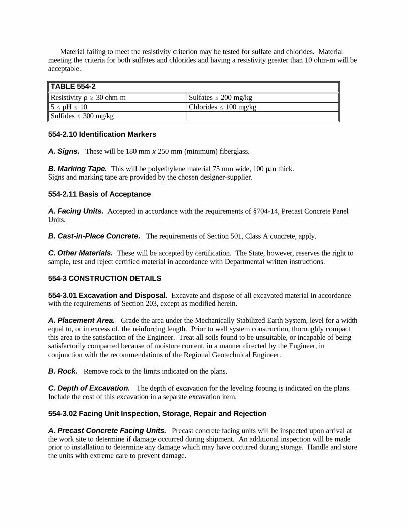
Material failing to meet the resistivity criterion may be tested for sulfate and chlorides. Material meeting the criteria for both sulfates and chlorides and having a resistivity greater than 10 ohm-m will be acceptable. TABLE 554-2 Resistivity D $ 30 ohm-m Sulfates # 200 mg/kg 5 # pH # 10 Chlorides # 100 mg/kg Sulfides # 300 mg/kg
554-2.10 Identification Markers A. Signs. These will be 180 mm x 250 mm (minimum) fiberglass. B. Marking Tape. This will be polyethylene material 75 mm wide, 100 :m thick. Signs and marking tape are provided by the chosen designer-supplier. 554-2.11 Basis of Acceptance A. Facing Units. Accepted in accordance with the requirements of §704-14, Precast Concrete Panel Units. B. Cast-in-Place Concrete. The requirements of Section 501, Class A concrete, apply. C. Other Materials. These will be accepted by certification. The State, however, reserves the right to sample, test and reject certified material in accordance with Departmental written instructions. 554-3 CONSTRUCTION DETAILS 554-3.01 Excavation and Disposal. Excavate and dispose of all excavated material in accordance with the requirements of Section 203, except as modified herein. A. Placement Area. Grade the area under the Mechanically Stabilized Earth System, level for a width equal to, or in excess of, the reinforcing length. Prior to wall system construction, thoroughly compact this area to the satisfaction of the Engineer. Treat all soils found to be unsuitable, or incapable of being satisfactorily compacted because of moisture content, in a manner directed by the Engineer, in conjunction with the recommendations of the Regional Geotechnical Engineer. B. Rock. Remove rock to the limits indicated on the plans. C. Depth of Excavation. The depth of excavation for the leveling footing is indicated on the plans. Include the cost of this excavation in a separate excavation item. 554-3.02 Facing Unit Inspection, Storage, Repair and Rejection A. Precast Concrete Facing Units. Precast concrete facing units will be inspected upon arrival at the work site to determine if damage occurred during shipment. An additional inspection will be made prior to installation to determine any damage which may have occurred during storage. Handle and store the units with extreme care to prevent damage.

B. Tolerances. Units not meeting dimensional tolerances, as determined by the Engineer, will be rejected. Replace rejected units with units acceptable to the Engineer. C. Damaged Units. Repair damaged units in a manner approved by the Engineer. Units that the Engineer determines are not repairable will be rejected. Replace rejected units with units acceptable to the Engineer. D. Rejection Responsibility. Responsibility for the rejection of units delivered to the job site rests solely with the Engineer. 554-3.03 Structure Erection A. Methods and Equipment. Install units in accordance with the designer-supplier's working drawings and Installation Manual, unless otherwise modified by the Contract Documents, or the Engineer. Prior to installation of the units, furnish the Engineer with detailed information concerning the proposed construction method, as well as the specific construction equipment planned for use. Begin work only after receiving the Engineer's written approval of the proposed construction methods. B. Unreinforced Concrete Leveling Pad. Provide an unreinforced concrete leveling pad as required by the plans. Place the concrete in accordance with the requirements §555-3. The Engineer may waive any part of §555-3, that the Engineer determines is impractical. C. Unit Installation 1. Place units such that, after completion of compaction, the requirements of TABLE 554-3 are not exceeded. After placement, maintain each unit in position by a method acceptable to the Engineer. If wedges are used, do not allow them to remain in place below three panel unit heights during installation, and compaction. Remove all wedges remaining in the top three panel unit heights upon comple tion of the Mechanically Stabilized Earth System. External braces may be required for initial placements. Install joint fillers in the manner indicated by the Installation Manual. 2. Correct all misalignments of installed units in excess of the tolerances allowed by Table 554-3, in a manner satisfactory to the Engineer at no additional cost. 3. Govern the operations and procedures to prevent misalignment of the installed panel units. Precautionary measures include, but are not limited to, keeping vehicular equipment a minimum of one meter from the panel units. Within one meter of the panel units use compaction equipment meeting the requirements of 203-3.12B6. TABLE 554-3 FACING UNIT ALIGNMENT AND JOINT OFFSET TOLERANCES Horizontal Alignment " 7 mm/m Joint Offset per Unit " 13 mm Overall Vertical Plumbness (Top to Bottom of Wall System) " 4 mm/m D. Backfill 1. Place backfill materials, other than rock, at a moisture content less than, or equal to, the Optimum Moisture Content. Rework or replace, as determined by the Engineer, all backfill material placed at a moisture content in excess of the Optimum Moisture content. Determine the Optimum Moisture Content

in accordance with the latest Geotechnical Test Methods for compaction that incorporate moisture content determination. Rework or replace backfill material at no additional cost to the State. 2. Place granular backfill material in uniform layers not exceeding 300 mm loose lift thickness per layer. Compact each layer to a minimum of 95 percent of Standard Proctor Maximum Density in accordance with §203-3.12. 3. Place rock backfill in uniform layers not exceeding 400 mm loose lift thickness. Compact in accordance with requirements determined by the Engineer. E. Reinforcing 1. Place reinforcing in accordance with the designer-supplier’s recommendations or as described in the designer-supplier’s Installation Manual. 2. Prior to placement of the steel reinforcing, backfill the area within one meter of the panel units horizontally to within 25 mm or less, below the required reinforcing elevation. Roughly grade the backfill beyond the one meter line to the reinforcing elevation. Roughly grade the backfill for the geogrid reinforcing to the reinforcing elevation. 3. Before attaching the reinforcing to the panel units, repair all damage to the zinc coating in accordance with the requirements of §719-01. 4. Prior to the attachment of the reinforcing, as required, fill all openings, or attachment locations, with grease, or other protective material. Obtain the grease, or other protective materials from the chosen designer-supplier. 5. Place reinforcing normal to the panel units unless indicated otherwise by the plans. Take care to avoid breaking, distorting, or disturbing the reinforcing. Replace reinforcing which is broken, or distorted, as determined by the Engineer. 6. Connect geogrid reinforcing to the facing before placement of subsequent facing units, or as directed by the approved construction drawings. 7. Operate rubber tired equipment on top of geogrid reinforcing only at low speeds (less than 5mph) and without making sharp turns or braking sharply. Do not operate tracked equipment directly on geogrid reinforcing. Cover geogrid with a minimum 150 mm thick soil layer prior to operating tracked equipment over reinforced areas. 8. Repair or replace damaged geogrid in strict accordance with the designer-supplier’s written instructions. 554-4 METHOD OF MEASUREMENT. Determine the quantity as the total number of square meters of face area computed from the plans using the following limits: A. Vertical 1. Topmost surface of the leveling footing. 2. Topmost surface of the facing units.

B. Horizontal. Limits indicated on the plans. When computing quantity, take into consideration the possible variation in the elevations of the footing and top of facing units. No field measurements will be made unless the Engineer specifies in writing a change to the limits indicated on the plans. 554-5 BASIS OF PAYMENT 554-5.01 Mechanically Stabilized Earth System. Include in the unit price bid the cost of all labor, equipment, technical representation from the designer-supplier, and materials, including backfill, reinforcing, leveling footing, joint fillers, and coping, unless otherwise modified by the Contract Documents. 554-5.02 Excavation and Disposal. Excavation and disposal of excavated material will be paid for under a separate item. 554-5.03 Damaged Units. No payment will be made for damaged units, nor for units that do not meet dimensional tolerances. Repair, or replace such units as determined by the Engineer, at no additional cost to the State. 554-5.04 Reinforcing. No payment will be made for reinforcing that the Engineer orders replaced. Replace such reinforcing at no additional cost. 554-5.05 Water. Include the cost of adding water for backfill compaction in the unit price bid for the Mechanically Stabilized Earth System, unless items for Furnishing Water Equipment and Applying Water are included in the Contract. If these items are included, include the cost of adding water in their bid prices. Payment will be made under: Item No. Item Pay Unit 554.01XX M Mechanically Stabilized Earth System, No Color Square Meter 554.02XX M Mechanically Stabilized Earth System, Integral Color Square Meter XX Surface 01 Plain Concrete Surface 02 Textured Surface (hand tooled, raked, etc.) 03 Exposed Aggregate Surface 04 Architectural Pattern (form liner or stamped) 05 As Shown on Plans SECTION 555 - STRUCTURAL CONCRETE 555-1 DESCRIPTION. This work shall consist of furnishing and placing portland cement concrete for structures as indicated on the plans and in accordance with the specifications. 555-2 MATERIALS 555-2.01 General. The materials used for structural concrete shall comply with the material requirements of Section 501, Portland Cement Concrete, General. Additiona l materials, listed below, required specifically for use in conjunction with structural concrete items shall meet the requirements of the following subsections:
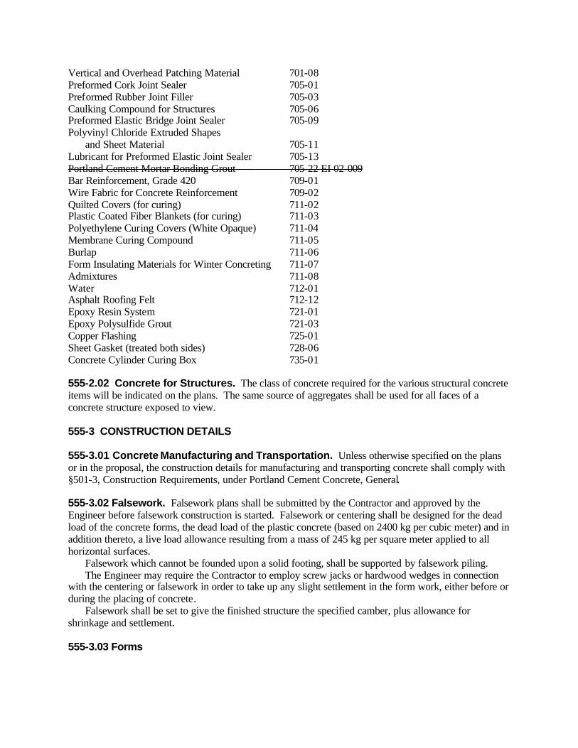
Vertical and Overhead Patching Material 701-08 Preformed Cork Joint Sealer 705-01 Preformed Rubber Joint Filler 705-03 Caulking Compound for Structures 705-06 Preformed Elastic Bridge Joint Sealer 705-09 Polyvinyl Chloride Extruded Shapes and Sheet Material 705-11 Lubricant for Preformed Elastic Joint Sealer 705-13 Portland Cement Mortar Bonding Grout 705-22 EI 02-009 Bar Reinforcement, Grade 420 709-01 Wire Fabric for Concrete Reinforcement 709-02 Quilted Covers (for curing) 711-02 Plastic Coated Fiber Blankets (for curing) 711-03 Polyethylene Curing Covers (White Opaque) 711-04 Membrane Curing Compound 711-05 Burlap 711-06 Form Insulating Materials for Winter Concreting 711-07 Admixtures 711-08 Water 712-01 Asphalt Roofing Felt 712-12 Epoxy Resin System 721-01 Epoxy Polysulfide Grout 721-03 Copper Flashing 725-01 Sheet Gasket (treated both sides) 728-06 Concrete Cylinder Curing Box 735-01 555-2.02 Concrete for Structures. The class of concrete required for the various structural concrete items will be indicated on the plans. The same source of aggregates shall be used for all faces of a concrete structure exposed to view. 555-3 CONSTRUCTION DETAILS 555-3.01 Concrete Manufacturing and Transportation. Unless otherwise specified on the plans or in the proposal, the construction details for manufacturing and transporting concrete shall comply with §501-3, Construction Requirements, under Portland Cement Concrete, General. 555-3.02 Falsework. Falsework plans shall be submitted by the Contractor and approved by the Engineer before falsework construction is started. Falsework or centering shall be designed for the dead load of the concrete forms, the dead load of the plastic concrete (based on 2400 kg per cubic meter) and in addition thereto, a live load allowance resulting from a mass of 245 kg per square meter applied to all horizontal surfaces. Falsework which cannot be founded upon a solid footing, shall be supported by falsework piling. The Engineer may require the Contractor to employ screw jacks or hardwood wedges in connection with the centering or falsework in order to take up any slight settlement in the form work, either before or during the placing of concrete. Falsework shall be set to give the finished structure the specified camber, plus allowance for shrinkage and settlement. 555-3.03 Forms

A. General. All forms shall be well-constructed, carefully aligned, substantial and firm, securely braced and fastened together in their final position. They shall be strong enough to prevent the fresh concrete from bulging the forms between supports and to withstand the action of mechanical vibrators. If required by the Engineer, form work plans shall be submitted by the Contractor and approved by the Engineer before forms shall be used on the work. No work shall be done without the approval of the Engineer. Forms shall be designed to resist a pressure resulting from a mass of 2400 kg per cubic meter for the plastic concrete and in addition thereto, a live load allowance resulting from a mass of 245 kg per square meter on horizontal surfaces. Forms shall be maintained to eliminate the formation of joints due to shrinkage of the lumber. They shall be sufficiently tight to prevent leakage of mortar. Concrete with surfaces misshapen by bulges or deformations caused by inadequate forms shall be removed or corrected as directed by the Engineer. When concrete is transported by buggies, conveyor belt or other approved methods of conveyance, the forms shall be capable of supporting the distribution equipment and any concentrations of concrete which may occur during transportation and distribution. Buggy runways and other supporting platforms shall be supported directly by the forms. The form and falsework design shall provide for the loads resulting from the conveyance system in addition to the live load allowance resulting from a mass of 245 kg per square meter. Forms for slabs, beams and girders shall be cambered as indicated on the plans. Forms shall be so constructed that those surfaces on which finishing may be required may be stripped without disturbing the remaining forms. Forms shall be filleted 25 mm at all exposed corners unless otherwise shown on the plans. Forms may be constructed of wood, metal or other approved materials except when a particular material is specified on the plans. When curved, patterned or other special forms are required, the Contractor shall submit details of the form construction to the Engineer for approval prior to constructing the forms. Construction of such forms shall not begin without the approval of the Engineer. The use of fiber forms will be permitted for round columns only if the interior surface of the forms have been treated in such a manner as to prevent helical corrugation marks on the finished concrete surface. Forms shall be adequately braced to resist concrete design loads. If the forms are inadequately braced, the Engineer shall stop concrete placement until adequate bracing has been provided. Any metal ties or anchorages within the forms shall be so constructed that the embedded portion of the ties can be removed to a depth of at least 50 mm from the surface of the concrete without injury to such surface. Wire ties will not be permitted without written permission of the Engineer. In case wire ties are permitted, all wires, upon removal of the forms, shall be cut back at least 6 mm from the face of the concrete with sharp chisels or nippers (nippers are necessary for green concrete.) All cavities produced by the removal of metal ties shall be filled in conformance with requirements of §555-3.08A, Finishing Surfaces Exposed to View. The surface film on repaired surfaces shall be carefully removed before setting occurs. All forms shall be set and maintained true to the line designated until the concrete is sufficiently hardened. For walls where access to the bottom of the forms is not practicable, the lower form boards or panels shall be left loose so that the inside of the forms can be readily cleaned of all chips, dirt, sawdust or other extraneous material, immediately prior to the placing of concrete. Forms to be re-used shall be maintained in good condition as to accuracy of shape, strength, rigidity, water tightness and smoothness of surface. Any warped or bulged forms must be carefully re-sized before being re-used. Forms unsatisfactory in any respect shall not be used. All form surfaces that will be in contact with the concrete shall be thoroughly treated with an approved form coating in the manner, and at the rate specified by the manufacturer. Only those coatings listed on the Approved List published

by the Materials Bureau are acceptable. Forms so treated shall be protected against damage or dirt prior to placing concrete. If metal forms are used, the material shall be of such thickness that the forms will remain true to shape. All bolt and rivet heads shall be countersunk. Clamps, pins or other connecting devices shall be designed to hold the forms rigidly together and to allow removal without injury to the concrete. Metal forms, which do not present a smooth surface or line up properly, shall not be used. Special care shall be exercised to keep metal forms free from rust, grease or other foreign matter that would tend to discolor the concrete. B. Removal of Forms. Forms and their supports shall be removed when ordered by the Engineer and then only in such manner as the Engineer may direct. Forms shall be removed in such a way as to permit the concrete to take the stresses uniformly and gradually. Any method of form removal likely to cause over stressing of the concrete shall not be used. The forms for any portion of a structure shall not be removed until the concrete is strong enough to withstand damage. The following minimum curing periods may be used as a guide for removal of forms and supports from concrete structures: Arch Centers 8 Curing Days Centering under Beams 8 Curing Days A curing day is defined in 555-3.09A. Forms used for substructure concrete placements shall be removed in accordance with the requirements of Table 555-1. 555-3.04 Handling and Placing Concrete A. General. No concrete shall be placed when the ambient air temperature is below 7EC, unless the Engineer grants permission under the provisions of §555-3.06. If the ambient air temperature is 7EC, or greater, during the placement and is expected to fall below 0EC, at any time during the curing period, the provisions of §555-3.06 shall apply. If the ambient air temperature is 7EC, or greater, during the placement and is expected to remain at, or above 0EC during the curing period, the provisions of §555-3.09 C. Curing Temperatures - All Placements shall apply. No structural slab or sidewalk placement shall be commenced if the combination of ambient air temperature, relative humidity, wind speed, and plastic concrete temperature, all combine such that a surface moisture evaporation rate is theoretically equal to, or greater than 1.2 kg/m2/hr. of exposed surface. It shall be the contractor's responsibility to determine this rate. (Refer to §555-3.09C, and TABLE 555-3). All foreign matter of every kind shall be removed from the interior of the forms before placing concrete. Temporary studs or braces within the forms shall be removed when the concrete has reached an elevation rendering their further use unnecessary. TABLE 555-1 MINIMUM TIME REQUIRED FOR STRIPPING FORMS, FORMING NEXT PLACEMENT AND LOADING OF SUBSTRUCTURES
STRIPPING FORMING NEXT PLACEMENT
LOADING
All Footings 2 Days 2 Days 4 Days before next placement Abutment Stems, Backwalls
2 Days if less than 3.0 m (avg.). Add 1 day for each additional 1.5 m up to 5 days, maximum
2 Days
5 Days before placing backwall on stem. 7 Days before backfilling 14 Days before placing superstructure loads.3
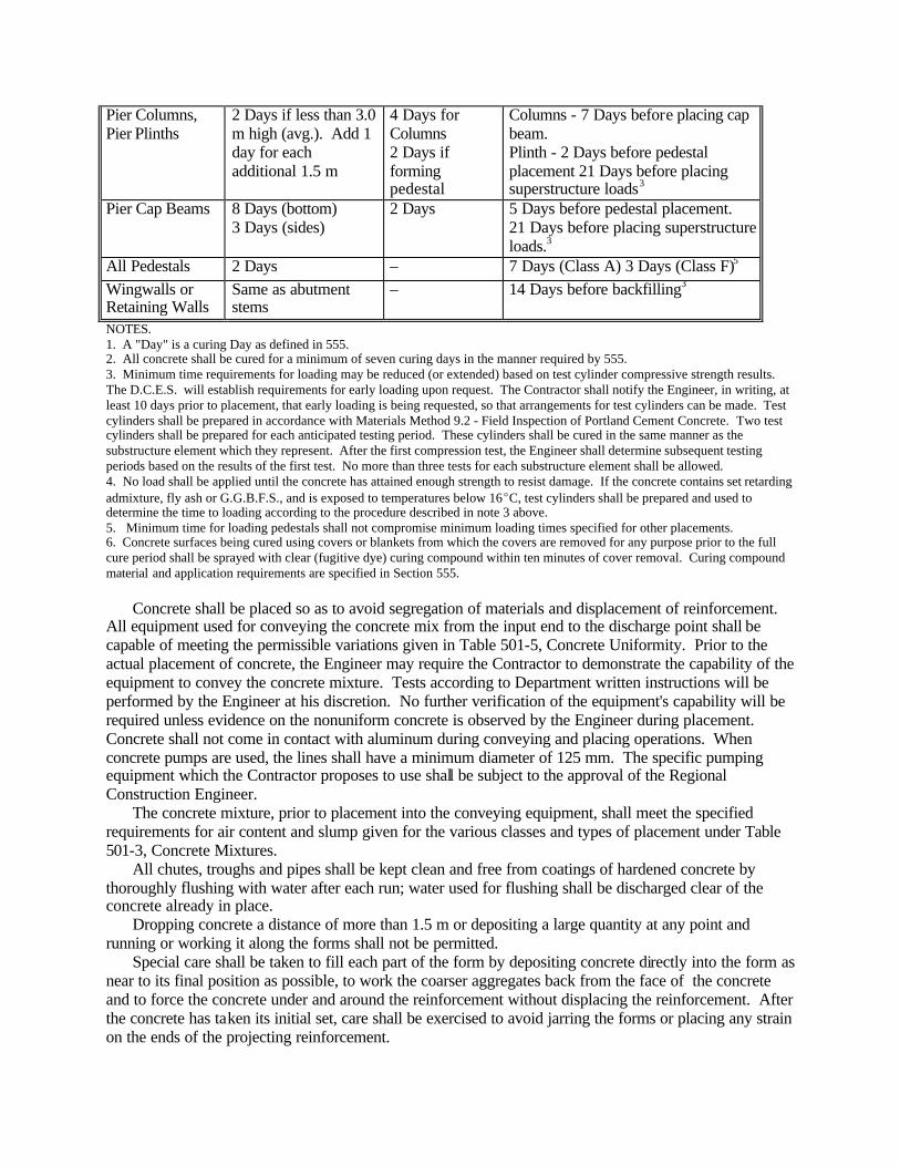
Pier Columns, Pier Plinths
2 Days if less than 3.0 m high (avg.). Add 1 day for each additional 1.5 m
4 Days for Columns 2 Days if forming pedestal
Columns - 7 Days before placing cap beam. Plinth - 2 Days before pedestal placement 21 Days before placing superstructure loads3
Pier Cap Beams 8 Days (bottom) 3 Days (sides)
2 Days 5 Days before pedestal placement. 21 Days before placing superstructure loads.3
All Pedestals 2 Days – 7 Days (Class A) 3 Days (Class F)5 Wingwalls or Retaining Walls
Same as abutment stems
– 14 Days before backfilling3
NOTES. 1. A "Day" is a curing Day as defined in 555. 2. All concrete shall be cured for a minimum of seven curing days in the manner required by 555. 3. Minimum time requirements for loading may be reduced (or extended) based on test cylinder compressive strength results. The D.C.E.S. will establish requirements for early loading upon request. The Contractor shall notify the Engineer, in writing, at least 10 days prior to placement, that early loading is being requested, so that arrangements for test cylinders can be made. Test cylinders shall be prepared in accordance with Materials Method 9.2 - Field Inspection of Portland Cement Concrete. Two test cylinders shall be prepared for each anticipated testing period. These cylinders shall be cured in the same manner as the substructure element which they represent. After the first compression test, the Engineer shall determine subsequent testing periods based on the results of the first test. No more than three tests for each substructure element shall be allowed. 4. No load shall be applied until the concrete has attained enough strength to resist damage. If the concrete contains set retarding admixture, fly ash or G.G.B.F.S., and is exposed to temperatures below 16EC, test cylinders shall be prepared and used to determine the time to loading according to the procedure described in note 3 above. 5. Minimum time for loading pedestals shall not compromise minimum loading times specified for other placements. 6. Concrete surfaces being cured using covers or blankets from which the covers are removed for any purpose prior to the full cure period shall be sprayed with clear (fugitive dye) curing compound within ten minutes of cover removal. Curing compound material and application requirements are specified in Section 555. Concrete shall be placed so as to avoid segregation of materials and displacement of reinforcement. All equipment used for conveying the concrete mix from the input end to the discharge point shall be capable of meeting the permissible variations given in Table 501-5, Concrete Uniformity. Prior to the actual placement of concrete, the Engineer may require the Contractor to demonstrate the capability of the equipment to convey the concrete mixture. Tests according to Department written instructions will be performed by the Engineer at his discretion. No further verification of the equipment's capability will be required unless evidence on the nonuniform concrete is observed by the Engineer during placement. Concrete shall not come in contact with aluminum during conveying and placing operations. When concrete pumps are used, the lines shall have a minimum diameter of 125 mm. The specific pumping equipment which the Contractor proposes to use shall be subject to the approval of the Regional Construction Engineer. The concrete mixture, prior to placement into the conveying equipment, shall meet the specified requirements for air content and slump given for the various classes and types of placement under Table 501-3, Concrete Mixtures. All chutes, troughs and pipes shall be kept clean and free from coatings of hardened concrete by thoroughly flushing with water after each run; water used for flushing shall be discharged clear of the concrete already in place. Dropping concrete a distance of more than 1.5 m or depositing a large quantity at any point and running or working it along the forms shall not be permitted. Special care shall be taken to fill each part of the form by depositing concrete directly into the form as near to its final position as possible, to work the coarser aggregates back from the face of the concrete and to force the concrete under and around the reinforcement without displacing the reinforcement. After the concrete has taken its initial set, care shall be exercised to avoid jarring the forms or placing any strain on the ends of the projecting reinforcement.
Concrete shall be placed in horizontal layers not more than 300 mm thick except as hereinafter provided. When less than a complete layer is placed in one operation, it shall be terminated in a vertical bulkhead. Each layer shall be placed and compacted before the preceding layer has taken its initial set to prevent injury to the green concrete and avoid cold joints between batches. Each layer shall be compacted so as to avoid the formation of a joint with a preceding layer which has not taken initial set. When concrete placement is temporarily discontinued, the concrete, after becoming firm enough to retain its form, shall be cleaned of laitance and other objectionable material to a depth sufficient to expose sound concrete. To avoid visible joints as far as possible upon exposed faces, the top surface of the concrete adjacent to the forms shall be smooth and level whenever concreting is discontinued. Where a “feather edge” would be produced at a construction joint, as in the sloped top surface of a wing wall, an inset form work shall be used to produce a blocked out portion in the preceding layer which shall produce an edge thickness of not less than 150 mm in the succeeding layer. Work shall be continuous from the bottom to the top of any face. The surface of all unformed areas, whether permanent or at construction joints, shall be finished by placing an excess of material in the forms and striking off the excess with a suitable screed, forcing the coarse aggregate below the level of the finished surface. Following the discontinuance of placing concrete, all accumulation of mortar splashed upon the reinforcing steel and the surfaces of forms shall be removed. Dried mortar chips and dust shall not be puddled into the plastic concrete. Before concrete slabs are placed on steel spans, all permanent field connections shall be completed unless otherwise noted on the contract plans, and all temporary supports and mechanisms used in steel erection shall be removed. When noted on the contract plans, the permanent field connections shall be made after the bridge slab has attained sufficient strength to permit removal of forms and falsework. Permanent field connections shall be made just prior to removal of forms and falsework. The placing of concrete for any bridge slab shall be continuous between joints. When embedding structural shapes in concrete, the placement of concrete shall be progressed on one side of the shape only until it flushes up over the bottom flange of the shape on the opposite side, after which concrete shall be placed on both sides to completion. B. Vibrating. During and immediately after deposition, concrete shall be thoroughly compacted by vibrating the concrete internally with mechanical vibrating equipment. Internal mechanical vibrators shall be sturdy and of a type approved by the Engineer. They shall be adequately powered, capable of transmitting vibration to the concrete in frequencies of not less than 3,500 impulses per minute and shall produce a vibration of sufficient intensity to consolidate the concrete into place without separation of the ingredients. The vibratory element shall be inserted into the concrete at the point of deposit and in areas of plastic concrete. The time of vibration shall be of sufficient duration to accomplish thorough consolidation, complete embedment of the reinforcement, produce smooth surfaces free from honeycombing and air bubbles, and to work the concrete into all angles and corners of the forms, however, over vibration shall be avoided. Vibration shall be continued in one place until the concrete has become uniformly plastic but not to the extent that pools of grout are formed. The duration of vibration will depend upon the frequency of the vibration (impulses per minute), size of vibrators and the slump of the concrete. This length of time must be determined in the field. The internal vibrators shall be inserted in the concrete at evenly spaced intervals not farther apart than the radius over which the vibration is visibly effective and at a distance close enough to the forms to effectively vibrate the surface concrete. The vibrator shall not be used to push or distribute the concrete laterally. The vibrating element shall be inserted in the concrete mass at a depth sufficient to vibrate the bottom of each layer effectively, in as nearly a vertical position as practicable. It shall be withdrawn comple tely from the concrete before being advanced to the next point of application. Internal vibrators shall not be placed directly on the forms or the reinforcing steel.

To secure even and dense surfaces, free from aggregate pockets or honeycomb, vibration shall be supplemented by working or spading by hand in the corners and angles of forms and along form surfaces while the concrete is plastic. A sufficient number of vibrators shall be employed so that, at the required rate of placement, thorough consolidation is secured throughout the entire volume of each layer of concrete. Extra vibrators shall be on hand for emergency use and when other vibrators are being serviced. The use of external vibrators will be permitted when satisfactory surfaces cannot be obtained by internal vibration alone or when it is impossible to use internal vibrators. The use of external vibrators shall be subject to the approval of the Engineer. External vibrators shall be attached to, or held on the forms in such a manner as to effectively vibrate the concrete in a horizontal plane. 555-3.05 Depositing Structural Concrete Under Water A. General. Concrete shall not be exposed to the action of water before setting, nor be deposited in water, except when noted on the plans or with the approval of the Engineer. When concrete is so deposited, it shall be Class G concrete with an approved retarder added. B. Placement. Concrete deposited under water shall be carefully placed in its final position by means of a tremie-250 mm minimum diameter or a pipe line - 125 mm minimum diameter. For the purposes of this subsection, the terms tremie, and pipe line are interchangeable. A tremie shall consist of a watertight tube system constructed in such a manner that it may only be moved vertically. Tremie spacings shall be approximately 10 m on center, or five meters from tremie to form. The support system for the tremie shall permit the tremie to rest on a firm surface, or be held flush with a soft surface, as necessary. No aluminum products shall be used for tremie construction. The tremie shall be clearly marked incrementally to permit visual observation and determination of vertical movements. Increments may be placed at any convenient equal measurement; however, they shall not be less than 100 mm, or greater than 1000 mm (one meter) apart. Actual concrete placement may be accomplished by either of the following methods: 1. An open ended tremie. This method requires the use of a go-devil which is a buoyant object, or material (e.g. sponge ball, hay/ burlap ball, vermiculite, etc.) to separate concrete from water, and prevent the concrete from free falling through the water. The following procedure shall be used to begin the concrete placement: Insert, into the tremie, a go-devil, acceptable to the Engineer which is not collapsible at the maximum water pressure. Determine the distance necessary to raise the tube sufficiently to permit the go-devil's escape from the tremie's bottom end upon concrete addition. This determination shall be made prior to the placement of concrete into the tremie. Upon determination, the proper distance shall be marked upon the outside of the tremie, using the increments as a guide. If the go-devil is spherical, the permissible distance is limited to the diameter of the tremie. Prior to placement of any concrete, raise the tremie the distance previously marked. Then place concrete in the tremie at a regular continuous pace which will force the go-devil to the bottom of the tube and out of the tremie thereby expelling the water. If this procedure is done correctly, the concrete column in the tremie should be just less than one-half the water depth upon go-devil discharge. The concrete level inside the tremie will rise as the concrete level outside rises. 2. A dry, closed end tremie. This method requires an easy release end cap, which will release when the fluid concrete pressure exceeds the water pressure. Determine the distance necessary to permit the opening of the end seal cap and mark this distance on the tremie prior to the insertion of concrete. Generally, this distance should not exceed the tremie diameter. Then raise the tremie and add concrete as noted for Method No. 1. Regardless of which method is used to place the concrete the following requirements shall apply:

! No concrete shall be placed in running water, nor subjected to the action of running water prior to initial set. ! All form work shall be constructed to properly retain underwater concrete. ! Concrete placement shall begin at the lowest placement elevation. ! The concrete surface shall be kept as nearly horizontal as practicable at all times. ! The discharge end of the tremie shall be kept embedded in fresh concrete until completion of the placement. ! Once begun, the concrete placement shall continue until all of the concrete designated at a specific location has been placed. C. Dewatering. Unless otherwise noted on the contract plans, dewatering may proceed no less than seven days following the placement of concrete. The Engineer may direct additional waiting time if considered necessary. All laitance or other unsatisfactory material shall be removed from the exposed surface by scraping, chipping or other means until sound concrete is exposed. If a leveling course of concrete is required, the concrete shall be as specified in this subsection except that the size of coarse aggregate shall be reduced to suit the condit ions of placement using the maximum size of aggregate possible. The concrete leveling course shall be preceded by a layer of portland cement grout well brushed onto the prepared concrete surface. One or more sumps shall be formed at the top surface of each concrete seal, to provide for the pumping of water leaking through the sheet piling, after the seal has been dewatered. All sumps shall be filled with concrete when it is no longer necessary to maintain the cofferdam in a dry condition. D. Test Cores. Test cores shall be drilled by the Contractor under the direction of the Engineer to determine the quality of the concrete seal after the cofferdam has been dewatered. The cores shall be drilled using NX barrels (54 mm). They shall be drilled at the locations shown, and to the depths indicated, on the contract plans. The exact locations shall be as directed by the Engineer. The Contractor shall exercise due care to obtain maximum recovery of cores since less than 100% is presumed to indicate defective concrete. Should the cores reveal voids, sand pockets, seams, or other defects in the concrete seal, additional cores shall be drilled, at the expense of the Contractor, for further investigation. The number and location of these additional cores shall be as directed by the Engineer. All voids, sand pockets and seams shall be cleaned out and filled by pressure grouting with cement or sand cement grout to the satisfaction of the Engineer. The Engineer shall be present and keep a complete record of the work at the time of grouting each holes. The Contractor's proposed grouting methods and grout mixes shall be subject to the approval of the Engineer. Any other defects revealed by the cores shall be repaired in a manner satisfactory to the Engineer. 555-3.06 Provisions for Concreting in Cold Weather A. General. When permission is granted in writing by the Engineer for cold weather concreting, the curing temperature shall be maintained between 7EC and 30EC for the curing durations stated in §555-3.09, Curing. Curing temperatures shall be maintained by either of the following methods for any placement except bridge slabs: ! Provision of external heat. ! Utilization of heat of hydration retained by insulated forms. Bridge slab placements shall be cured as required by Section 557.
Thermometers of the specified type required for determining the temperature under these cold weather concreting provisions shall be supplied by the Contractor. Measurements will be taken by the Engineer and a temperature record will be maintained for the curing period. The thermometers shall be placed at the following locations: ! Walls: At each corner, both sides of the beam vertically and at the midpoint of both sides horizontally. ! Beams: At each corner, both sides of the beam vertically and at the midpoint of both sides horizontally. ! Pier Columns: Two at the top of the column. One shall be placed in the path of the normally prevailing winds, the other diametrically opposite the first. A third thermometer shall be placed halfway up the column, preferably not in the path of the normally prevailing winds. ! Footings: One at each corner of the top face, and one each at the midpoint of the longest sides horizontally. ! Other: As established by the Engineer. Thermometers shall consist of the following types: ! Continuously Recording Thermometer: The thermometer shall be capable of continuously recording temperatures within a range of -20EC to 50EC for a minimum of 24 hours. ! Maximum - Minimum Recording Thermometer: For all placements the thermometer shall be capable of recording maximum and minimum temperatures within a range of -20EC to 50EC. When concrete is to be placed in contact with steel members, reinforcing steel or previously placed concrete, the temperature of the steel and concrete shall be raised to approximately 7EC by a method approved by the Engineer before concreting begins. When concrete is to be placed in contact with earth or rock, the temperature of the earth or rock shall be 2EC or higher. The earth or rock shall not have any snow, frost, or standing water on its surface. B. Provision of External Heat. If the Contractor is required, or elects, to maintain curing temperatures by this method, the Contractor shall furnish sufficient canvas and framework, or other type of housing, to enclose and protect the structure in such a way that the air surrounding the fresh concrete can be kept at a temperature between 7EC and 30EC for the specified curing period. At the end of the curing period, the heat shall be gradually reduced at a rate not to exceed 0.5 degree C per hour until the temperature within the enclosure equals the temperature outside the enclosure. Enclosures used for bridge slab pours shall completely enclose the intended slab on all six sides. There shall be sufficient room between the top of the reinforcing steel and the top of the enclosure to allow placement of concrete by any normal means. The bottom of the enclosure shall be below the lowest portion of the superstructure. External heat shall be provided by means of stoves, salamanders, or steam equipment supplied and operated by the Contractor at his expense. Sufficient equipment shall be supplied to continuously maintain the specified temperature with a reasonable degree of uniformity in all parts of the enclosure. The enclosures shall be properly vented to prevent surface disintegration of fresh concrete due to an accumulation of carbon dioxide gas. All exposed concrete surfaces within the heated area shall be kept wet during the heating period unless heat is supplied in the form of live steam. Materials and equipment necessary to erect the enclosure and provided external heat shall be present on the job site and approved by the Engineer before any concrete is placed. Heating appliances shall not be placed in such a manner as to endanger formwork or centering or expose any area of concrete to drying out or injury due to excessive temperatures.

External heat shall be applied for the required curing period except that structural slabs shall have external heat applied for a minimum of fourteen (14) curing days. C. Heat Retention by Insulated Forms. If the Contractor elects to maintain curing temperatures by this method, the Contractor shall furnish sufficient insulation and protection to maintain the temperature between the insulation and formwork within the range of 7EC to 30EC for the specified curing period. Discontinuance of protection shall be accomplished in such a manner that the drop in temperature of any portion of the concrete shall be gradual. The surface temperature of concrete sections more than 610 mm in thickness shall not drop faster than 10EC in a 24 hour period. The surface temperature of concrete sections less than 610 mm in thickness shall not drop faster than 20EC in a 24 hour period. Forms may be removed without restriction providing the temperature difference between the air and the surface of the concrete is not more than 15EC. If possible, forms shall be removed about the middle of the day to take advantage of the generally higher afternoon temperatures. Form insulating material shall be installed on the forms in such a manner so as to achieve the full benefit of its insulating properties and at the same time provide against the infiltration of wind and water. All portions of steel forms shall be covered by insulating material so that no steel is exposed to the air. Any tears or damaged areas in the insulating material shall be repaired to the satisfaction of the Engineer. Special attention shall be given to ensure that all corners and angles are properly insulated and protected against wind damage. Where tie rods extend through the form insulating material, a plywood washer (20 mm x 150 mm x 150 mm approx.) shall be placed over the tie rod and against the insulating material. The washer shall be secured in a manner satisfactory to the Engineer. After placement of the concrete, the exposed concrete surfaces shall be covered with insulating blankets, except for areas where protruding reinforcing bars make the use of blankets impracticable. These areas may be covered with hay or other insulating material approved by the Engineer. Tarpaulins shall be used to protect the insulating material as directed by the Engineer. The insulating material shall be either insulating blankets, bat insulation, solid foam, or sprayed foam meeting the requirements of Section 711-07, Form Insulating Materials for Winter Concreting. The thickness of standard blankets, or bat insulation, required for varying air temperatures, concrete thicknesses and cement contents of the mix are listed in Table 555-2. The actual thickness of the insulating material used shall be determined by multiplying the equivalency factor for the insulating material by the thickness shown on Table 555-2. The equivalency factors for all approved insulating materials are given on the Approved List. If the temperature of the concrete surface, or the temperature be tween the form and the covering, falls below 7EC during any one day of the curing period, that day will not be a curing day. The length of the curing period will be extended until the total required number of curing days are accumulated. If the temperature of the concrete surface, or the temperature between the form and the covering falls below 0EC at any time during the curing period, the concrete will be rejected. TABLE 555-2 MINIMUM AIR TEMPERATURE ALLOWABLE FOR INSULATION FOR CONCRETE WALLS, PIERS AND ABUTMENTS ABOVE GROUND (EC)
Thickness of Commercial Blanket or Bat Insulation (mm) Cement Content (kg/m3)
Wall Thickness (mm)
13 25 40 50
150 7 2 -5 -10
300 2 -9 -27 -32
450 -3 -19 -36 -54
300
600 -5 -23 -45
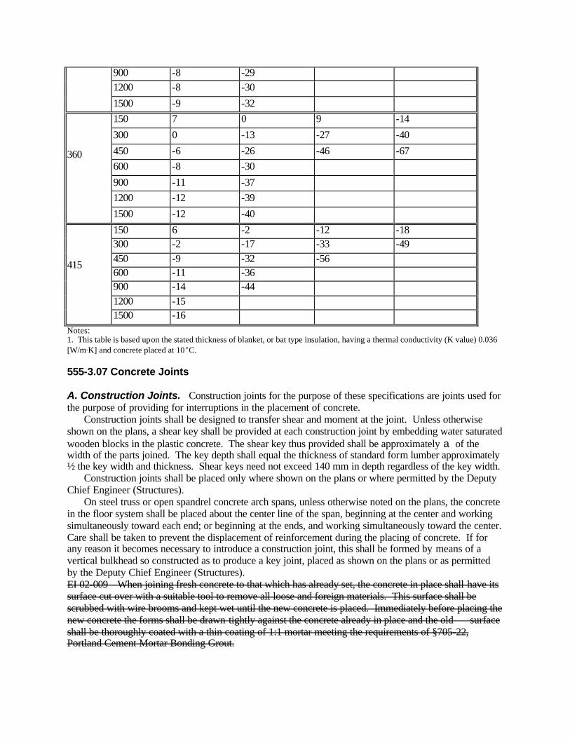
900 -8 -29 1200 -8 -30
1500 -9 -32 150 7 0 9 -14
300 0 -13 -27 -40
450 -6 -26 -46 -67 600 -8 -30
900 -11 -37 1200 -12 -39
360
1500 -12 -40
150 6 -2 -12 -18 300 -2 -17 -33 -49 450 -9 -32 -56 600 -11 -36 900 -14 -44 1200 -15
415
1500 -16 Notes: 1. This table is based upon the stated thickness of blanket, or bat type insulation, having a thermal conductivity (K value) 0.036 [W/mAK] and concrete placed at 10EC. 555-3.07 Concrete Joints A. Construction Joints. Construction joints for the purpose of these specifications are joints used for the purpose of providing for interruptions in the placement of concrete. Construction joints shall be designed to transfer shear and moment at the joint. Unless otherwise shown on the plans, a shear key shall be provided at each construction joint by embedding water saturated wooden blocks in the plastic concrete. The shear key thus provided shall be approximately a of the width of the parts joined. The key depth shall equal the thickness of standard form lumber approximately ½ the key width and thickness. Shear keys need not exceed 140 mm in depth regardless of the key width. Construction joints shall be placed only where shown on the plans or where permitted by the Deputy Chief Engineer (Structures). On steel truss or open spandrel concrete arch spans, unless otherwise noted on the plans, the concrete in the floor system shall be placed about the center line of the span, beginning at the center and working simultaneously toward each end; or beginning at the ends, and working simultaneously toward the center. Care shall be taken to prevent the displacement of reinforcement during the placing of concrete. If for any reason it becomes necessary to introduce a construction joint, this shall be formed by means of a vertical bulkhead so constructed as to produce a key joint, placed as shown on the plans or as permitted by the Deputy Chief Engineer (Structures). EI 02-009 When joining fresh concrete to that which has already set, the concrete in place shall have its surface cut over with a suitable tool to remove all loose and foreign materials. This surface shall be scrubbed with wire brooms and kept wet until the new concrete is placed. Immediately before placing the new concrete the forms shall be drawn tightly against the concrete already in place and the old surface shall be thoroughly coated with a thin coating of 1:1 mortar meeting the requirements of §705-22, Portland Cement Mortar Bonding Grout.

“When joining fresh concrete to concrete that has already set, the concrete in place shall have its surface scoured or abraded with a suitable tool to remove all loose and foreign materials. This surface shall be scrubbed with wire brooms. After the surface preparation has been accepted, every effort should be made to thoroughly wet the concrete surface, and all porous surfaces to be in contact with new concrete, for 12 hours. This may be accomplished by continuous wetting with soaker hoses or the use of burlap/burlene/etc. where moisture can be maintained. If, in the opinion of the Engineer, conditions or the situation prohibits this, then the surfaces should be wetted for as long as possible. Construction joints must be wetted by a means acceptable to the Engineer using potable water. The Contractor shall remove any puddles of free standing water with oil-free compressed air, and protect the surfaces from drying, so the existing concrete remains in a clean, saturated surface dry condition until placement of the new concrete. Immediately before placing the new concrete, the forms shall be drawn tightly against the concrete already in place.” EI 02-009 Forms for female shear keys shall be beveled on four sides to facilitate their removal and shall be securely fastened to the forms to prevent displacement before the concrete has set. Key forms shall be removed in such a manner as to avoid injury to the concrete. B. Contraction Joints. Contraction joints shall be placed at locations shown on the plans and unless otherwise specified, shall be formed the same as construction joints except that reinforcement shall not extend through the joint. C. Expansion Joints. Expansion joints shall be placed at locations shown on the plans and shall be constructed as detailed thereon. Expansion joints shall provide for expansion, contraction and the transfer of shear at the joint unless otherwise specified. When expansion joints are formed by the insertion and subsequent removal of joint templates, this work shall be done in such a manner that joint edges are not chipped or broken down in the process. When concrete is to be placed against a joint filler, holes or joints in the filler shall be suitably filled with mastic to prevent mortar or concrete from entering the joint and restricting its movement. The face edges of all joints shall be carefully finished or formed true to line and elevation for a minimum distance of 50 mm back from all exposed surfaces. When caulking compound is used to seal a joint containing premolded bituminous joint filler, a layer of an approved type of pressure-sensitive release tape shall be placed between these materials because of their incompatibility. D. Waterstops. Waterstops shall be installed in joints as shown on the plans. Should the drawings fail to indicate a waterstop in any joint exposed to view, the Contractor shall install a waterstop of polyvinyl chloride or other approved flexible material, copper strip, zinc strip or lead sheet. The waterstop shall extend at least 75 mm into the concrete on each side of the joint, shall be joined to be continuous and watertight and shall be carefully protected from damage until covered by concrete or backfill. Waterstops shall be manufactured, formed and installed so as to provide for expansion and contraction movements at the joint. 555-3.08 Finishing A. Finishing Surfaces Exposed to View. Immediately after forms have been removed, surfaces exposed to view shall have all projections and irregularities carefully removed and all cavities neatly filled with mortar of the proportion used in the concrete. The same brand of cement and the same kind of

aggregate shall be used for filing cavities as was used in the original concrete mix. Plastering of surfaces shall not be allowed. The surface film of all such repaired surfaces shall be carefully removed before setting occurs. All top surfaces of parapets, copings, walls and bridge seats shall be finished by placing an excess of material in the forms and removing or striking off such excess with a suitable screed, forcing the coarse aggregate below the mortar surface. The use of mortar topping for surfaces falling under this classification shall not be permitted.

All rust and other stains shall be removed from concrete exposed to view. Removal shall be
Figure 555-1 STRUCTURAL CONCRETE EVAPORATION RATE

accomplished using methods and materials approved by the Engineer. Materials used for rust stain removal shall be as listed on the Approved List published by the Department's Materials Bureau. B. Finishing Bearing Surfaces. The entire surface area of bridge seats or pedestals shall be floated and troweled to true grade or, at the option of the Contractor, left approximately 6 mm high and bush hammered or otherwise finished to the exact elevations indicated on the plans. C. Sidewalk Finish on Bridges. Sidewalks shall be constructed by placing concrete continuously to an elevation slightly higher than shown on the plans. The concrete shall then be screeded to the correct elevations and worked with a wooden float to give uniform surface. Floating shall be kept to a minimum, consistent with the desired finish, in order to avoid overworking the concrete. Surface scoring will not be permitted. 555-3.09 Curing A. General. All structural concrete shall be cured for a minimum of seven curing days unless otherwise stated. A curing day is defined as any day, starting with the day of placement, during which the ambient air temperature at the concrete surface is 7EC or higher. Conditions may occur which prevent an entire day from qualifying as a curing day, but do not prevent portions of that day from reaching temperatures that qualify as curing temperatures. If these conditions occur and with the Engineer's permission, the Contractor may aggregate curing hours. A curing hour is defined as any hour during which the curing temperature remains at, or above 7EC. An aggregation of 24 curing hours will be credited as one curing day. Aggregations of less than 24 curing hours will not be credited. Curing hours will be determined with continuous recording thermometers, capable of measuring temperatures in the -1EC to 38EC range, over a 24 hour period. The number and placement of the thermometers will be determined by the Engineer. Provide all equipment, supplies and labor necessary for calibration. Include cost of the calibration in the unit price bid. Structural concrete may be cured by any one, or a combination of, the following methods unless otherwise noted: ! Curing covers. ! Clear (fugitive dye) membrane curing compound. This method will not be allowed as a curing method for structural slabs, either alone, or in combination with other methods. ! Continuous burlap wetting. ! Wet burlap and curing covers. Curing covers shall be placed as soon after concrete finishing as the Engineer determines will not cause damage to the concrete surface. However, in no case will the foregoing time period exceed 30 minutes. Curing covers shall be lapped a minimum of 300 mm. All lapped edges shall be sealed with pressure sensitive tape. Covers shall be protected from displacement in a manner approved by the Engineer. Clear (fugitive dye) membrane curing compound shall be sprayed on the concrete surface immediately following the finishing operation, or form removal, whichever is applicable. The compound shall be applied by means of a pressure spraying system, or by distributing equipment, at the rate directed by the Engineer. Under no circumstances, however, shall the rate be less than 1 L per 3.5 m2 of surface. The equipment for applying the compound shall be such that the compound is applied as a fine spray with no surface damage to the concrete. The equipment shall also provide for adequate agitation of the compound during application, and shall be approved by the Engineer before work is started. Should the application method produce a non-uniform film, or should the spraying equipment fail and duplicate equipment is not immediately available, the

application shall cease. Curing shall then be continued by another method acceptable to the Engineer. The Contractor shall provide sufficient approved covers for protection of the concrete surface in the event of rain or equipment breakdown. No special provisions for curing will be required for surfaces where forms are left in place, except that in extremely hot weather, the Engineer may require the forms to be wetted to reduce surface heat. If forms are removed during the curing period (refer to 555-3.03B), the concrete curing shall be continued using a clear (fugitive dye) membrane curing compound. B. Exposed Concrete Surfaces. All exposed concrete surface, including fascias, which do not require forms shall be cured using curing covers or a clear (fugitive dye) membrane curing compound. 1. Curing Covers. a. Plastic Coated Fiber Blankets. These shall meet the requirements of §711-03, they shall be laid dry with the fiber side against the concrete. b. Polyethylene Curing Covers (white opaque). These shall meet the requirements of §711-04. 2. Clear (fugitive dye) Membrane Curing Compound. This shall meet the requirements of §711-05. C. Curing Temperatures - All Placements. The curing temperature of concrete is the air temperature at the concrete surface, or the air temperature between the concrete surface and its protective covering. Temperatures at these locations are critical for proper concrete curing. For the purposes of this section the temperatures at the foregoing locations shall be maintained between 7EC and 30EC inclusive. Should the ambient air temperature be out of the 7EC to 30EC range during curing, the following shall apply in addition to the requirements of §555-3.09B . 1. Temperatures below 7EC. If the ambient air temperature falls, or is expected to fall, below 7EC, but remain above 0EC the Contractor shall propose a suitable method to maintain the curing temperature at, or above, 7EC during the curing period. All proposed methods shall meet the approval of the Engineer. To provide assurance of the methods employed, the Contractor shall supply maximum-minimum thermometers. The number and placement of the thermometers shall be determined by the Engineer. Thermometers shall have a temperature range between -20EC to 50EC inclusive. The Engineer will maintain a temperature record during the curing period. If the curing temperature falls below 7EC, the day during which that occurs will not be a curing day. The Engineer shall notify the Contractor and the Contractor shall modify the existing method employed to maintain the curing temperature. The length of the curing period will be extended until the required number of curing days are accumulated. If the method employed by the Contractor to retain heat fails and the curing temperature falls below 7EC, but remains above 0EC, for twenty-four (24) consecutive hours, then the provisions of §555-3.06 shall apply. If the curing temperature falls below 0EC, at any time during the curing period, the concrete will be rejected. 2. Temperatures above 30EC. If the ambient air temperature exceeds 30EC, provide seven days of continuous, uniform wetting for curing. Leave all burlap in place for seven (7) curing days.
555-3.10 Weep Holes. The Contractor shall construct weep holes in all retaining walls and abutments at such points as are indicated on the plans or designated by the Engineer. 555-3.11 Damaged or Defective Concrete. Damaged or defective concrete shall be defined by and repaired in accordance with the requirements of Section 502, Portland Cement Concrete Pavement, and §502-3.14, Damaged or Defective Concrete. Patching material meeting the requirements of §701-08, Vertical and Overhead Patching Material shall be used for patching vertical or overhead surfaces. 555-3.12 Foundation Concrete. The footings of structures shown on the plans shall be considered as approximate only and, when ordered in writing by the Deputy Chief Engineer (Structures) shall be changed to such dimensions as will give a satisfactory foundation. Concrete shall not be placed in any foundation form without the Engineer's approval. When Footing Concrete, Class A is specified; Class HP may be substituted for all footing placements, and Class H may be substituted when the footing is 1 meter thick or less. 555-4 METHOD OF MEASUREMENT 555-4.01 Concrete for Structures. Payment for each item will be made for the number of cubic meters within the lines of the structure as shown on the plans or as revised by authority of the Engineer. In computing the volume of concrete for payment, no deductions shall be made for the volume of joint material, embedded metal reinforcement, structural shapes, chamfers, tops of piles, or pipe with an end area of less than 0.10 m2. 555-5 BASIS OF PAYMENT 555-5.01 General. When the Contractor elects to substitute an optional concrete class as permitted by Table 501-1, Concrete Class Options, payment will be made for the originally specified class of concrete using the originally specified method of measurement. 555-5.02 Concrete for Structures. The unit price bid per cubic meter for each class of concrete, shall include the cost of furnishing all labor, materials and equipment necessary to complete the concrete work as shown on the plans or called for in the specifications, except reinforcement will be paid for separately under its appropriate item. Unless otherwise provided, the unit price bid shall include the cost of furnishing and placing copper flashing or other metal strips, flexible water stops, sheet packing, pipe drains, bituminous material, water for wetting, joint materials, felt, tar paper, joint sealing compounds, joint fillers and concrete curing materials. No extra compensation for falsework or falsework piling will be paid. This work is included as part of the formwork. All replacements or corrections to concrete surfaces misshapen by bulges or deformations shall be made at the Contractor's expense. All additional concrete that may be ordered by the D.C.E.S. for concrete footings that are below or beyond the lines shown on the plans will be paid for at the unit price bid in the contract. Bridge bearings, expansion joints and anchor bolts will be paid for under their appropriate items. No payment will be made for concrete replacement or other corrective work which the Contractor is directed to perform in accordance with the requirements of Section 556, Reinforcing Steel for Concrete Structures, §556-3.02E, Placement in Structural Slabs. Progress payments will be made, after the concrete and curing applications have been properly placed, to the extent that payment will be made at 90% of the computed quantity of each concrete placement, with the balance to be paid after completion of all curing and corrective work thereon. Payment will be made under:
Item No. Item Pay Unit 555.0104 M Footing Concrete, Class A
(No Concrete Class Substitutions Allowed, except as permitted in §555-3.12) Cubic Meter
555.0105 M Concrete for Structures, Class A Cubic Meter 555.05 M Concrete for Structures, Class F Cubic Meter 555.06 M Concrete for Structures, Class G (Deposited Under Water) Cubic Meter 555.07 M Concrete for Structures, Class GG (Deposited Under Water) Cubic Meter 555.08 M Footing Concrete, Class HP Cubic Meter 555.09 M Concrete for Structures, Class HP Cubic Meter SECTION 556 - REINFORCING STEEL FOR CONCRETE STRUCTURES 556-1 DESCRIPTION. The work will consist of furnishing and placing reinforcing steel for concrete structures, or stud shear connectors, in accordance with the contract plans, and in a manner satisfactory to the Engineer. Reinforcing steel for concrete structures may be either epoxy-coated or uncoated. 556-2 MATERIALS. Materials for this work shall meet the requirements of the following subsections of Section 700, Materials: Bar Reinforcement, Grade 420 709-01 Wire Fabric for Concrete Reinforcement 709-02 Epoxy Coated Wire Fabric Reinforcement 709-08 Epoxy Coated Reinforcement 709-04 Stud Shear Connectors 709-05 Mechanical Connectors for Reinforcing Bar Splices 709-10 556-2.01 Epoxy-Coated Reinforcement. Chairs, tie wires, and other devices used to support, position, or fasten the reinforcement shall be made of or coated with, a dielectric material. The specific hardware that the Contractor proposes to use shall be approved by the Engineer. 556-2.02 Uncoated Reinforcement. When permanent corrugated metal forms are used, chairs, slab bolsters, and other devices used to support, position, or fasten the reinforcement shall be made of or coated with a dielectric material. Stainless steel chairs without polyethylene tips and meeting the requirements of ASTM A493, AISI Type 430, may also be used. The specific hardware that the Contractor proposes to use shall be subject to approval by the Engineer. When forms are to be removed in their entirety, uncoated steel chairs equipped with snug fitting, high density, polyethylene tips which provide 6 mm clearance between the metal and any exposed surface may be used. Stainless steel chairs meeting the requirements of ASTM A493, AISI Type 430, may be used without polyethylene tips. Chairs that are made of, or coated with, a dielectric material, may also be used. The specific hardware that the Contractor proposes to use shall be subject to approval by the Engineer. 556-3 CONSTRUCTION DETAILS 556-3.01 General A. Storing and Handling Epoxy-Coated Bar Reinforcement Steel. All epoxy-coated bar reinforcement shall be stored above ground on wooden or padded supports.

Epoxy-coated bar reinforcement stored on-site shall be protected from sunlight and moisture using opaque waterproof covers. Covers shall be placed in a manner that will permit constant air circulation so as to minimize the formation of condensation on the epoxy-coated bar surface. All equipment for handling epoxy-coated bars shall have padded contact areas. All bundling bands shall be padded and all bundles shall be lifted with a strong back, multiple supports, or a platform bridge so as to prevent bar-to-bar abrasion from sags in the bar bundle. Bars, or bundles of bars, shall not be dropped or dragged. Care shall be taken at all times to prevent damage to the epoxy coating. B. Placing and Fastening Bar Reinforcement Steel. Prior to placing bar reinforcement steel all grease, dirt, mortar and any other foreign substances shall be removed. Loose rust and loose millscale on uncoated reinforcement shall be removed by wire brushing. Steel bar reinforcement shall be placed in the position indicated on the plans and within the allowable tolerances specified. Before concrete is placed, all reinforcement shall be securely fastened and supported with approved chairs or other approved devices. C. Inspection. Concrete shall not be placed until the bar reinforcement steel is inspected and permission for placing concrete is granted by the Engineer. All concrete placed in violation of this provision shall be rejected and removed. 556-3.02 Bar Reinforcement A. Ordering. Prior to ordering reinforcing steel, the Contractor shall carefully check all bar lists, and assume full responsibility for their accuracy. No change in the bar list shall be made by the Contractor unless approved by the D.C.E.S. B. Field Bending 1. Epoxy - Coated Bar Reinforcement. The alternatives of shop bending or field bending of epoxy coated bar reinforcement will be at the option of the Contractor. Field bending shall be done by cold methods only. Direct heating of the bars shall not be permitted. Field bending operations shall be allowed only when ambient and bar temperatures are 5EC or greater. When lower temperatures prevail the Contractor may supply, for field bending operations, a fully enclosed space that is heated and constructed to the satisfaction of the Engineer. No additional payment will be made for such an enclosure. Epoxy coated bar reinforcement damaged by field bending work shall be evaluated and repaired, or replaced, in accordance with the requirements of §556-3.02C. 2. Uncoated Bar Reinforcement. When bars are heated for field bending they shall not be heated to a temperature higher than that producing a dark cherry red color. Only competent personnel shall be employed and proper equipment provided for cutting and bending. The reinforcement shall be bent to the shapes shown on the plans. Unless shown otherwise on the plans, the radii of bends measured to the inside face of the bend bar shall be equal to, or greater than, three times the diameter of the bar. Bends in stirrups shall be equal to, or greater than, the diameter of the bar. C. Field Repair - Epoxy Coated Bar Reinforcement. The Contractor will be required to field repair damaged areas of the bar coating, and to replace bars exhibiting severely damaged coatings. The material used for field repair shall be that supplied by the coating applicator.

Field repair will be required on all areas of major damage. Major damage is defined as any defect or break in the epoxy coating 6 mm x 6 mm or greater. The total number of all major damaged areas which have been repaired with patching material shall not exceed five (5) in any three meter length of bar. Field repair will not be required on areas of minor damage. Minor damage is defined as any defect or break in the coating less than 6 mm x 6 mm. The maximum number of unrepaired minor damaged areas shall not exceed an average of six (6) per 300 mm on any individual bar. Field repair will not be allowed on bars which have severely damaged coatings as determined by the Engineer. A reinforcing bar having coating damage determined by the Engineer to exceed the above criteria shall not be incorporated in the work, and it shall be removed from the work site. All such bars shall be replaced in kind by the Contractor at no additional cost to the State. D. Splices. Splices shall be permitted only where shown on the contract plans. Should the Contractor desire to splice bars at locations other than those shown on the contract plans, written permission to do so shall first be obtained from the D.C.E.S. Such permitted splices shall be well distributed, or located, at points of low tensile stress. Splices shall not be permitted unless a minimum of 50 mm can be provided between the spliced bar and the nearest adjacent bar. Splices for bar sizes No. 36 or smaller, shall be made by means of a mechanical connector or by placing the bars in contact and wiring them together for the full length of the splice. Splices for bars larger than No. 36 shall be made by arc welding, or by use of a mechanical connector. Mechanical connections shall be used in accordance with the requirements of §709-10 Mechanical Connectors for Reinforcing Bar Splices. Splices made with mechanical connectors shall be installed in accordance with the manufacturer's written requirements. Arc welded splices shall be made and inspected in accordance with the provisions of the SCM, Section 7, Part D. Prior to welding of epoxy coated reinforcing bars, the epoxy coating shall be removed for the length to be welded plus 150 mm on each side of the weld. After welding, the spliced area shall be cleaned in accordance with Steel Structures Painting Council - Surface Preparation Specification No. 6 (SSPC-SP6), Commercial Blast Cleaning. The surface, after cleaning, shall be defined by SSPC-VIC 1-89, Pictorial Standards, BSP6, BSP6, BSP6, as applicable. A compatible epoxy repair material supplied by the coating applicator shall be applied to the spliced area and overlap the original coating by 150 mm. The epoxy repair material shall be applied the same day as the cleaning. E. Placement in Structural Slabs. Bar supports shall be spaced no farther apart than 1.2 m center-to-center, nor shall any bar support be closer than 150 mm from the edge of any future concrete surface. Bridge slab bar reinforcement shall be placed in accordance with the following tolerances: Vertical + 6 mm Horizontal + 13 mm The structural slab bar reinforcement mats (top and bottom) shall be securely connected together. This connection may be accomplished by wiring or other means approved by the Engineer. Connections shall be placed no farther apart than 1.2 m on centers. The bar supports may be utilized for this purpose. Connecting devices shall neither deflect the bar reinforcement nor interfere with the smooth flow of concrete. Chairs, tie wires and other similar devices used for epoxy-coated bar reinforcement shall meet the requirements of §556-2.01. Similar hardware used for uncoated bar reinforcement shall meet the requirements of §556-2.01 or §556-2.02. Immediately prior to placement of concrete, the Engineer shall verify that the reinforcing steel is positioned within the above-stated tolerances. If the allowable tolerances are exceeded, the Engineer shall order that the position of the reinforcing steel be corrected before granting permission for placing concrete.
Subsequent to placement of concrete, the Engineer shall verify at random that the vertical clear distance from the top of the structural slab to the top mat of main reinforcing, as shown on the contract plans, is correct within a tolerance of plus or minus 13 mm. If the allowable tolerance is exceeded, the Engineer shall reject the work and so advise the Contractor and the Deputy Chief Engineer (Structures), in writing, stating the deficiencies upon which the rejection is based. The Deputy Chief Engineer (Structures) shall review the nature and extent of the deficiencies and shall designate one or more of the following alternatives: ! The affected concrete placement shall be removed and replaced in whole or in part. ! The Contractor shall provide special corrective measures as directed by the Deputy Chief Engineer (Structures). ! The concrete placement shall be accepted without corrective action. The removal of the concrete placement and its subsequent replacement, or other corrective work which the Contractor is directed to perform, shall be accomplished at no additional cost to the State. 556-3.03 Stud Shear Connectors for Bridges. Stud shear connectors shall be shop or field welded to the structural steel members at the locations indicated on the plans. This work shall be done in accordance with the provisions of the SCM, Part 7C. 556-4 METHOD OF MEASUREMENT 556-4.01 Steel Fabric Reinforcement. The work will be measured as the number of square meters of fabric reinforcement stated in the Estimate of Quantities. Except to provide for progress payments, no field measurements will be taken. Measurements taken for progress payment purposes will not exceed the Estimate of Quantities figure. 556-4.02 Bar Reinforcement A. Uncoated Reinforcing Bars. These shall be measured as the number of kilograms of steel bars placed. The mass of bar reinforcing will be computed by the Engineer utilizing the unit mass for each size bar as given in Table 556-1. TABLE 556-1 UNIT MASS OF DEFORMED BARS Bar Number
10 (3)
13 (4)
16 (5)
19 (6)
22 (7)
25 (8)
29 (9)
32 (10)
36 (11)
43 (14)
57 (18)
Mass (kg/m)
0.580 0.994 1.552 2.235 3.041 3.973 5.060 6.404 7.907 11.38 20.24
Note. Numbers in parenthesis are bar sizes in numbers of eighths of inches. B. Epoxy-Coated Reinforcing Bars. The requirements of §556-4.02A shall apply. No allowance will be made for the mass of the epoxy coating. 556-4.03 Stud Shear Connectors for Bridges. Stud Shear Connectors shall be measured as each connector placed. 556-5 BASIS OF PAYMENT 556-5.01 Steel Fabric Reinforcement. The unit price bid per square meter shall include the cost of all labor, materials and equipment necessary to complete the work.
556-5.02 Bar Reinforcement. The unit price bid per kilogram shall include the cost of all labor, materials and equipment necessary to complete the work. The unit price shall also include the cost of chairs, supports, fastenings, connections, and any splices not specifically shown on the plans. If the Engineer permits the substitution of larger bars than those specified, or the D.C.E.S. permits splices not shown on the plans, payment will be made only for the amount of steel which would have been required if the specified size and length had been used. 556-5.03 Stud Shear Connectors for Bridges. The unit price bid per stud shall include the cost of all labor, materials and equipment necessary to complete the work. If the use of any stud shear connector requires payment of a royalty to the manufacturer, the royalty shall be included in the unit price bid for this work. Payment will be made under: Item No. Item Pay Unit 556.0101 M Uncoated Steel Fabric Reinforcement for Structures Square Meter 556.0102 M Epoxy Coated Steel Fabric Reinforcement Square Meter 556.0201 M Uncoated Bar Reinforcement for Concrete Structures Kilogram 556.0202 M Epoxy-Coated Bar Reinforcement for Structures Kilogram 556.03 M Stud Shear Connectors for Bridges Each SECTION 557 - SUPERSTRUCTURE SLABS AND STRUCTURAL APPROACH SLABS 557- 1 DESCRIPTION. The work shall consist of placing high performance (Class HP) concrete to construct superstructure slabs, structural approach slabs, sidewalks, and safety walks, as required by the plans. 557-1.01 Options. Unless otherwise noted the contractor may use any of the following forming systems to form the underside of the superstructure slabs: A. Removable forms B. Permanent corrugated metal forms C. Prestressed concrete form units 557-1.02 Restrictions. The following restrictions shall apply: A. Fascia overhangs shall be formed with removable forms. The forms used shall leave the resulting concrete flat surfaced. B. A bay, constructed in stages such that a longitudinal joint is required, shall be formed with removable forms. C. A haunch which rests upon an end diaphragm shall be formed with removable or permanent corrugated metal forms. D. Prestressed concrete form units shall not be used where the design span is less than 1.5 meters nor greater than 3.3 meters. The design span is equal to the beam spacing minus one-half the top flange width.

E. Prestressed concrete form units may be restricted at the ends of some skewed spans. Refer to the plans for details. F. Prestressed concrete form units shall not be used on prestressed concrete box beam superstructures unless specifically allowed by the plans. 557-2 MATERIALS A. Concrete. This shall meet the material requirements for Class HP in accordance with Department directives. Unless otherwise directed by the Engineer, all concrete shall contain a set retarding, water reducing admixture, meeting the requirements of §711-08. The quantity of the admixture shall be sufficient to achieve the minimum retardation consistent with placing conditions. The dosage rate used shall be determined by the Contractor in accordance with the manufacturer’s recommendation and in concurrence with the Regional Materials Engineer. The dosage shall remain consistent for the duration of the concrete placement except for minor adjustments to meet changing environmental conditions. B. Other Materials. These shall meet the following requirements: All material listed under §555-2.01 shall apply. 555-2.01 Epoxy coated bar reinforcement 709-04 Prestressed concrete form units 718-05 Permanent Corrugated Metal Forms for Bridge Slabs 736-01 Chairs, tie wires, and other devices used 556-2.01 to position reinforcing steel 556-2.02 557-3 CONSTRUCTION DETAILS 557-3.01 Concrete Manufacturing and Transportation. The requirements of §501-3 shall apply. 557-3.02 Falsework. The requirements of §555-3.02 shall apply. 557-3.03 Forms A. Removable Forms. The requirements of §555-3.03A shall apply. B. Permanent Corrugated Metal Forms for Superstructure Slabs. Where permanent metal forms are employed, the following construction procedures shall apply: Care and protection shall be given the metal form sheets, supports and accessory items during handling, shipping and storage. During loading, hoisting and unloading operations, extra precaution and care shall be taken to prevent damage to ends, corners and edges of the form sheets, supports and accessory items. If the form units and accessories are to be stored prior to installation, they shall not be placed in contact with the ground and the material shall be adequately covered or protected to keep it dry. Form supports shall be placed in direct contact with the flange of stringer or floor beam. All attachments shall be made by permissible welds, bolts, clips or other approved means. The welding of form supports to steel not considered weldable or to portions of flanges subject to tensile stresses shall not be permitted. Welds, and welding shall be in accordance with the provisions of the SCM, Section 7, except that 3 mm fillet welds will be permitted. All welding shall be performed by a New York State Department of Transportation Certified Welder whose qualifications permit performing the work. Form sheets shall not be permitted to rest directly on the flanges. They shall be securely fastened to form supports by self-tapping screws and shall have a minimum bearing length of 25 mm at each end.

Transverse construction joints shall be located at the bottom of a flute and 6 mm weep holes shall be field drilled at not less than 300 mm on centers along the line of the joint. Screed and pouring runway supports shall not be located directly on the form sheets, form supports or reinforcing steel. No loose sheets or miscellaneous hardware shall be left on the structural slab at the end of the working day. Metal forms shall not be used where longitudinal slab construction joints are located between stringers, nor shall they be used on the fascia overhang. The corrugated metal sheets shall be fabricated for the placement sequence used with the joints between sections of sheet overlapped or securely fastened to eliminate differential deflections between sections. Any exposed form metal where galvanizing has been damaged, shall be cleaned and repaired as provided for in §719-01, Galvanized Coatings and Repair Methods. The following inspection procedures will be used as a check to insure the soundness of the concrete structural slab adjacent to the steel forms. Not less than two days after completion of concrete structural slab pour, but prior to the next slab pour, a section of the steel form shall be removed from the most recently completed pour of each span, at a location selected by the Engineer, in order to provide visual evidence that the concrete mix or the construction procedures are obtaining the desired results. If either the concrete mix or the construction procedures are varied significantly within a pour, such as a change in the extent of vibration or change in the workability of the mix, another section of form shall be removed to verify that the new procedures are yielding desirable results. After the concrete has been placed in a span for a minimum of ten days but prior to any further work performed on the superstructure in that span, the Engineer will spot-check the underside areas of the steel forms by sounding with a suitable weight hammer at least 50% of the area of at least 25% of the individual form panels on a random basis to determine whether any honeycomb or void areas exist. If such areas are detected, the Contractor shall remove the forms from these areas for a visual inspection of the slab. The amount of sounding and form removal may be moderated, at the Engineer's discretion, after a substantial amount of slab has been constructed and inspected, if the Contractor's methods of construction and the results of the inspections as outlined above indicated that sound concrete is being obtained throughout the slabs. If, after removing a section of form, the concrete is found to be defective, additional panels shall be removed as directed by the Engineer. All defective concrete shall be repaired to match the adjacent concrete in section and color to the satisfaction of the Engineer. The Contractor shall provide all facilities required for safe, suitable and convenient means of access to the forms for the Engineer's inspection procedures. The form sections shall be removed by a metal saw or air-carbon-arc gouging with minimum damage to the concrete. Cuts shall only be sufficiently deep to sever the form. Any other method of removal shall be submitted to the Deputy Chief Engineer (Structures) for approval. Cuts that are parallel to the corrugations in the forms shall be located on the sloping surface midway between a crest and a valley. Cuts parallel to the supporting beams shall be made through the supporting angles taking care not to damage the structural steel beams. The Contractor will not be required to replace the removed forms. C. Prestressed Concrete Form Units. The applicable requirements of §555-3.03A and the Prestressed Concrete Construction Manual shall apply. Form supports shall be placed in direct contact with the flange of the stringer. All attachments shall be made by permissible welds, bolts, or other means approved by the Engineer. The welding of form supports to steel not considered weldable, or to portions of flanges subject to tensile stresses will not be permitted. Welds and welding shall be in accordance with those portions of the New York State Steel Construction Manual concerned with fillet weld design, fillet weld details; general workmanship and technique, except that 3 mm fillet welds will be permitted. All welding shall be performed by a New York State Department of Transportation Certified Welder whose qualifications permit performing the work.

557-3.04 Removal of Forms. The requirements of §555-3.03B shall apply. 557-3.05 Placing and Fastening Reinforcing Steel A. Except for prestressed concrete form units the requirements of §556-3.01 and §556-3.02 shall apply. B. Prestressed Concrete Form Units. The requirements of §556-3.01 and §556-3.02 shall apply, except that the second paragraph of §556-3.02E which begins with “The structural..." and ends with “...of concrete." shall not apply. The following shall apply instead: "The top reinforcing steel mat shall be securely connected to the forms and the stud shear connectors. Connections shall be placed no farther apart than 1.2 meters on center. Connections to the forms may be made to the form lifting devices, reinforcing steel projecting from the forms, or devices in the form supplied for this purpose. Hold down devices shot into the form will not be permitted. Connections shall neither deflect the reinforcing steel, nor interfere with the smooth flow of concrete. 557- 3.06 Handling and Placing Concrete. The requirements of §555-3.04 shall apply. A Pre- placement Meeting will be required between the Contractor and the Engineer at least one week prior to the start of any concrete placement for superstructure slabs. The Contractor and the Engineer will review all aspects of the proposed placement including, but not limited to, the following: ! Equipment proposed for use and for back-up ! Planned workforce and assigned tasks of each designated position, based on experience and expertise
! Proposed construction techniques
! Safety considerations
! Concrete mix design
! Admixtures and performance data; dosage rates shall be approved by the Regional Materials Engineer
! Proposed placement rate, curing and loading schedules
! Curing Practices to be employed as well as the workforce designated to the curing process ! Delivery/ conveyance equipment, including deck finishing machine setup and operation
! Traffic control No concrete shall be placed until all aspects of the proposed placement are approved by the Engineer. Modifications must be submitted in writing to the Engineer for approval. No concrete shall be placed until all the provisions of §555-3.04A are met, environmental conditions are deemed favorable, and satisfactory means to mitigate adverse environmental conditions exist. Favorable environmental conditions are defined as an expected weather forecast suitable for concrete placement during the entire placement duration, the evaporation rate not to exceed 1.2 kg/m²/hr, and acceptable curing temperatures expected for the duration of the curing period. The Contractor shall provide any necessary means to mitigate adverse weather conditions and curing temperatures with the approval of the Engineer. Failure to maintain acceptable environmental conditions will result in the concrete placement being stopped and a bulkhead put in place. The Contractor shall take the necessary measurements and calculate the theoretical evaporation rate. The measurements for air temperature, relative humidity, and wind speed shall be taken as near as possible to the final placement location of the concrete. Concrete temperature will be taken from the same sample used for slump and air content tests. These measurements will be taken prior to commencement of concrete placement. If, in the Engineer's opinion, significant changes occur in atmospheric conditions, additional atmospheric measurements and calculations by the Contractor will be required. The Contractor shall supply all instruments necessary to make the required calculations. All instruments shall be certified by an independent laboratory, approved by the Engineer, as being in good working order, and as having been calibrated within the 12 months prior to use. The Contractor’s measurements and calculations will be subject to the Engineer's approval.

Vibrating of concrete shall be in accordance with §555-3.04B except as modified herein. All internal vibrators shall have a rubberized or elastomeric cover to prevent damage to epoxy coated reinforcing bars. The vibrators and covers will be inspected for defects prior to use and shall be subject to the approval of the Engineer. The number of vibrators required shall be one for every 30 cubic meters of concrete placed per hour, with a minimum of two vibrators in use at all times, and equally spaced across the placement front. One additional vibrator shall be available for use as a back-up. 557-3.07 Provisions for Concreting in Cold Weather. When permission is granted in writing by the Engineer for cold weather concreting, the curing temperature shall be maintained between 7EC and 30EC for the curing durations stated in §555-3.09, Curing. Curing temperatures shall be maintained by the provision for external heat in accordance with §555-3.06B. Thermometers meeting the requirements of §555-3.06A1 shall be supplied by the Contractor and placed within the enclosure as directed by the Engineer to represent extreme temperature conditions. A minimum of two thermometers shall be supplied. The Engineer may require additional thermometers. The temperature recordation shall continue for the entire curing period. When concrete is to be placed in contact with steel members, reinforcing steel or previously placed concrete, the temperature of the steel and concrete shall be raised to approximately 7EC by a method approved by the Engineer before concreting begins. When concrete is to be placed in contact with earth, the temperature of the earth or rock shall be 2EC or higher. The earth shall not have any snow, frost, or standing water on its surface. 557-3.08 Cold Joints. “Cold Jointing”, the bonding of fresh concrete to set concrete, shall be done where indicated on the plans, or where approved by the D.C.E.S. A. Horizontal Joints. Within 24 hours of the start of the deck placement, the tops of precast/prestressed elements shall have laitance and dirt removed by a high pressure water wash. The high pressure water wash shall be sufficiently strong to remove any laitance and dirt, but not damage the precast/prestressed units, reinforcement or reinforcement coating. The pressure wash equipment shall be capable of providing pressure of 21 MPa to 35 MPa. After pressure washing, the tops of precast/prestressed elements shall be continuously wetted for a minimum of 12 hours immediately prior to deck placement. Before placing fresh concrete, all standing water shall be removed with oil-free compressed air. The surface shall be protected from drying to maintain a clean, saturated surface dry condition when placing the deck. The same pressure washing and prewetting requirements shall be applied to deck surfaces prior to placement of sidewalks and safety walks. B. Construction Joints. Construction joints for the purpose of these specifications are joints used to provide for interruptions in the placement of concrete. Construction joints shall be designed to transfer shear and moment at the joint. Unless otherwise shown on the plans, a shear key shall be provided at each construction joint by embedding water saturated wooden blocks in the plastic concrete. The shear key thus provided shall be approximately a the width of the parts joined. The key depth shall equal the thickness of standard form lumber approximately ½ the key width and thickness. Shear keys need not exceed 140 mm in depth, regardless of the key width. Construction joints shall be placed only where shown on the plans or where permitted by the D.C.E.S. EI 02-009 The concrete in place shall have its surface scoured or abraded with a suitable tool to remove all loose and foreign materials. This surface shall be thoroughly blast cleaned to remove all laitance and loosened concrete. The surface shall be thoroughly wetted to provide a saturated surface dry condition at the time of concrete placement. Immediately before placing the new concrete, the forms shall be drawn tightly against the concrete in place. The existing concrete surface shall be thoroughly coated with mortar meeting the requirements of §705-22 Portland Cement Bonding Grout.
The mortar shall be worked into the prepared surface by means of stiff brushes, or other methods acceptable to the Engineer. Mortar shall not be allowed to begin to dry. If drying does begin to occur prior to concrete placement, as evidenced by a light grey color, the Engineer will order the mortar to be completely removed and new mortar placed at no additional cost to the State.
“When joining fresh concrete to concrete that has already set, the concrete in place shall have its surface scoured or abraded with a suitable tool to remove all loose and foreign materials. This surface shall be scrubbed with wire brooms. After the surface preparation has been accepted, every effort should be made to thoroughly wet the concrete surface, and all porous surfaces to be in contact with new concrete, for 12 hours. This may be accomplished by continuous wetting with soaker hoses or the use of burlap/burlene/etc. where moisture can be maintained. If, in the opinion of the Engineer, conditions or the situation prohibits this, then the surfaces should be wetted for as long as possible. Construction joints must be wetted by a means acceptable to the Engineer using potable water. The Contractor shall remove any puddles of free standing water with oil-free compressed air, and protect the surfaces from drying, so the existing concrete remains in a clean, saturated surface dry condition until placement of the new concrete. Immediately before placing the new concrete, the forms shall be drawn tightly against the concrete already in place.” EI 02-009 557-3.09 Finishing Integral Wearing Surfaces on Superstructure Slabs. The provisions of §502-3.09 Finishing and §502-3.10 Texturing, shall apply except as hereinafter modified. Machine finishing shall be used throughout all bridge paving operations with the exception of areas which are inaccessible to finishing machines. Machine finishing shall be accomplished with an approved power driven transverse finishing machine set 6 mm to 13 mm above the finished surface followed by an approved power driven longitudinal or transverse finishing machine. Machine finishing may also be accomplished by the use of an approved power driven one operation, (Strike-off and finishing), machine. All one operation machines shall be equipped with a power driven strike-off auger and a pan float. Backing up of finishing machines will not be permitted unless ordered by the Engineer. Finishing machines shall be equipped with adjustable strike-off and finishing screeds, the bottom surfaces of which shall be adjusted to produce the required contour of the finished surface. Machines shall be kept in true adjustment. Machines out of adjustment shall not be used until proper adjustments have been made and the adjustments have been approved by the Engineer. A sufficient amount of concrete equal to the finishing machine capacity shall be supplied at all times. The specific method and equipment that the Contractor proposes to use for finishing will be supplied during the Pre-placement Meeting and will be subject to approval by the Regional Construction Engineer. Screed supports shall be accurately set and of substantial construction so that the finished roadway surfaces will conform to the profile and transverse sections shown on the plans. Screed supports shall be placed and adjusted to properly provide for the deflection of forms, falsework and structural supporting members which will occur during the placement of the concrete. Screed rail supports shall not be attached by welding to portions of flanges subject to tensile stresses. The screed rail supports shall be spaced at a maximum of 600 mm on center. During stage construction, the screed support system shall be on the stage being placed. Where the roadway surface falls outside the fascia stringer flange, the screed supports shall be placed on the forms. The forms shall be designed to take these loads through the use of outriggers or some other approved means. Immediately before concreting operations are stated, the finishing machine shall be operated over the full length of the bridge segment to be paved. This test run shall be made with the screed adjusted to its

finishing position. While operating the finishing machine during this test the screed rails shall be checked for deflection and proper adjustment, the cover on slab reinforcement measured and the controlling dimensions of slab reinforcement and forms checked. All necessary corrections shall be made before concreting is begun. After the concrete has been placed, spread and consolidated to provide a uniformly dense structural slab, the surface shall be struck off immediately by the passage of the transverse finishing machine. The finishing machine shall carry sufficient concrete in front of the screed to fill low and porous places. This operation shall be done only once and shall produce a uniformly consolidated dense smooth surface of the required contour. The passage of the first finishing machine shall provide a concrete surface slightly above grade so that after settlement, if any, and the disappearance of excess water from the surface, the passage of the second finishing machine will result in a uniform surface at the required grade and contour over its entire area. Should an approved one operation (strike-off and finishing) machine, equipped with a strike-off auger(s) be used for finishing, the above procedure shall be followed except that there will be no second passage allowed. The first passage of the approved machine shall be the final passage. Care shall be taken not to overwork the concrete surface during the finishing operation. Hand finishing, when allowable, shall be performed in such a manner as to produce concrete surface quality and uniformity identical to that produced by the machine finishing. Finishing screeds shall be 250 mm, or more, in width. Screed surfaces, in contact with concrete, shall be steel. Hand operated screeds shall be used such that the action of the finishing machine is duplicated. Hand finishing shall be performed in the same sequence and manner as machine finishing, unless otherwise permitted by the Engineer. In the event the placement is delayed as a result of equipment breakdowns or delivery problems, all concrete in place shall be protected from evaporation by covering the surface with wet burlap, curing blankets, or plastic sheets. Excessive delays shall require the establishment of a bulkhead and the ceasing of the placement. Finished plastic concrete surfaces shall be uniformly smooth, dense and even. Variations of pavement surface in excess of 6 mm above or below, the elevation required by the plans shall not be accepted. Prior to texturing, the finished concrete surface shall be examined by the Contractor and the Engineer using a straight-edge approved by the Engineer. The straight-edge shall not be less than 3 m long. It shall be furnished by the Contractor, and maintained in good, usable condition, at the placement site at all times. While the concrete is still plastic, surface depressions shall be filled with concrete of the same class as the placement in progress. Surface irregularities greater than 5 millimeters in 3 meters in either the longitudinal, or the transverse direction shall be corrected in a manner acceptable to the Engineer. Thin mortar, or laitance, which may have accumulated ahead of the finishing screeds shall be removed from the work site. They shall not be used to fill depressions. After a uniformly smooth, dense, and even surface has been achieved, the surface shall be given a suitable texture with an artificial turf drag approved by the Engineer. The drag shall be made of molded polyethylene with synthetic turf blades approximately 13 mm long. There shall be approximately 64,000 blades per square meter. The artificial turf drag shall be of a type and brand appearing on the Department's approved list. The Contractor may texture in a transverse direction, longitudinal direction or parallel to the finishing machine . The Engineer shall be notified of the chosen direction at least one day prior to the placement of structural slab concrete. Once begun, the direction of texturing shall not change. All texturing shall be done from a work bridge placed no closer than 3 m from the back of the finishing machine. Texturing shall be done prior to the beginning of curing operations. Only one pass of the turf drag over the finished area will be permitted. If texturing is done in a transverse or skewed direction, the Contractor shall texture by hand methods as soon as practicable after finishing machine passage. If texturing is done in the longitudinal direction the turf drag shall be a seamless strip and shall be attached to the work bridge such that the surface of the concrete is textured as soon as practicable after finishing machine passage. Small areas, otherwise inaccessible to the attached drag, may be textured by

hand methods, if approved by the Engineer. Only one pass of the turf drag over the finished area will be permitted. The finishing movement and resulting progress of the turf drag shall be done in a manner so as to prevent ridges, or gouges forming in the concrete surface. The drag shall be weighted and the contact area changed as required to produce a texture acceptable to the Engineer. The drag shall be cleaned periodically as directed by the Engineer, to remove all hardened concrete particles. Texture resulting from the drag shall stop within 300 mm of curbs. 557-3.10 Finishing Integral Wearing Surfaces on Structural Approach Slabs. The requirements of §557-3.09 shall apply together with the following: The Contractor may use an approved, manually driven vibrator equipped power screed in lieu of a power driven transverse finishing machine. Only screed model types appearing on the Department's approved list shall be employed for this work. Should the Engineer determine that satisfactory results are not being attained, the Engineer may require the use of a power driven finishing machine. 557-3.11 Finishing Surfaces to be Overlaid with Portland Cement, or Asphalt, Concrete. Finishing of these surfaces shall be done by mechanical means except in areas which are inaccessible to a mechanical screeding operation. The equipment shall be approved by the Engineer prior to use. Surfaces shall be screeded to a surface tolerance of 10 mm in 3 meters. The surface tolerance shall be verified by the Engineer with an approved straight edge not less than 3 meters long. The straight edge shall be furnished by the Contractor who shall maintain it in good condition at the paving site at all times. Hand screeding, when required, shall be performed in such a manner as to produce the same surface quality and uniformity as that produced by mechanical screeding. Finishing screeds shall be 250 mm, or more, in width and the contacting surfaces shall be steel. Hand-operated equipment shall be used in such a manner as to duplicate the action of a mechanical screed. Hand-screeding shall be performed in the same sequence and manner as mechanical screeding unless otherwise directed by the Engineer. Upon completion of screeding, surfaces which will be overlaid with portland cement concrete shall be roughened in a manner acceptable to the Engineer. 557-3.12 Curing A. General. All exposed surfaces of superstructure slabs , and structural approach slabs shall be cured in the following manner: After finishing and plastic concrete texturing operations are completed, the concrete surface shall be completely covered with clean, prewetted burlap in accordance with the requirements of §555-3.09A, except that allowable time period for wet burlap covering shall not exceed five minutes from the completion of texturing, and 30 minutes from the time of concrete placement. Care shall be taken so as not to damage the finished surface and texturing. However, under no circumstances shall the curing be delayed beyond the specified period. Burlap shall meet the requirements of §711-06. It shall be lapped a minimum of 300 mm. Lapped edges are not required to be sealed. Burlap shall be thoroughly saturated over its entire surface area and shall be drained of excess water prior to its application. Burlap shall be kept continuously wet. Continuous burlap wetting shall commence 10 minutes from the time the wet burlap is placed. It shall be protected from displacement in a manner acceptable to the Engineer. 1. Superstructure Slabs. After the burlap placement has been fully completed, the concrete surface shall be cured for 14 curing days. The Contractor may use either option listed below. After seven curing days, the Contractor may be permitted to perform incidental work on the structure under the loading limitations of §557-3.14. The burlap may be displaced in limited areas, for short durations, to perform items such as sawcut grooving, placement of sidewalks, safety walks, curbing, bridge rail and fencing. The amount of burlap displaced to perform these operations shall be limited to the immediate area affected by the Contractor’s operations. All concrete surfaces exposed during these operations shall be

kept in a saturated condition. Immediately after the work is completed in the affected area, all burlap shall be replaced for the duration of the curing period. Removable forms shall remain in place until the minimum curing period is complete. a. Fourteen Day Continuous Wetting: Leave all burlap in place for 14 curing days. Provide continuous, uniform wetting for the entire curing period. b. Wet Burlap and Curing Covers: Provide continuous uniform wetting for seven curing days. After seven curing days, either of the following methods may be used: i. Remove all burlap after seven curing days have passed. Apply curing covers conforming to the requirements of §555-3.09 B immediately upon burlap removal. Plastic coated fiber blankets meeting the requirements of §711-03 are not required to be laid dry. Application and maintenance of covers shall be in accordance with §555-3.09 A. Concrete cured in this manner shall not be exposed to the atmosphere for more than 10 minutes between burlap removal and curing cover placement. ii. Apply curing covers conforming to the requirements of §555-3.09 B directly over the wet burlap. Plastic coated fiber blankets meeting the requirements of §711-03 are not required to be laid dry. Application and maintenance of covers shall be in accordance with §555-3.09 A. The concrete surface shall be inspected periodically to ensure that its condition remains saturated. The Contractor shall inform the Engineer of the intended curing procedure at the Pre-placement Meeting. 2. Structural Approach Slabs, Curbs, Sidewalks and Safety walks on Bridges. After the burlap placement has been fully completed, leave all burlap in place for 7 curing days. Provide continuous, uniform wetting for the entire curing period. Forms for curbs, sidewalks, and safety walks shall remain in place until the minimum curing period is complete. Forms for structural approach slabs shall remain in place until sufficient strength is achieved, as determined by the Engineer, to avoid damage to the concrete. After removal of approach slab forms, the formed surfaces shall be cured as per the requirements of §555-3.09B. B. Curing Temperatures. Only the requirements of §555-3.09C 1. and 2a shall apply. 557-3.13 Damaged or Defective Concrete. Damaged, or defective, concrete shall be defined by, and repaired in accordance with, the requirements of Section 502, Portland Cement Concrete Pavement, and §502-3.14, Damaged or Defective Concrete. §701-08, Vertical and Overhead Patching Material, shall be used for patching vertical or overhead surfaces. After the concrete has hardened, the Engineer will examine it using the Contractor’s straight-edge. Surface irregularities greater than 5 millimeters in 3 meters shall be corrected in a manner acceptable to the Engineer. Unless otherwise directed by the Regional Materials Engineer, the concrete used for repairs shall be of the same materials as that used for the original placement. All corrections shall be at the Contractor's expense. 557-3.14 Loading Limitations for Superstructure Slabs. Superstructure slabs, during the curing period, may be subjected to a vehicle load not to exceed nine metric tons, or a wheel load not to exceed three metric tons no sooner than seven calendar days after placement. Full legal loading may commence using either of the following options: A. Superstructure slabs may be subjected to full legal loads no sooner than 14 calender days after completion of the curing period.

B. The Contractor may subject a superstructure slab to its full legal load upon completion of the curing period, or any day thereafter provided that the procedure below is followed: 1. The Contractor shall notify the Engineer at the Pre-placement Meeting of the intention to subject the slab to full legal load prior to the 14th day after completion of curing. 2. During the slab concrete placement the Engineer will cast two sets (pairs) of test cylinders in addition to each set cast for record. 3. The Engineer will forward cylinders to the Materials Bureau or Regional Testing Facility. One set will be tested fourteen calendar days after placement and, if necessary, the second set will be tested twenty-one calendar days after concrete placement. Under no circumstances will cylinders be tested sooner than fourteen calendar days after the concrete placement they represent. 4. Concrete cylinder sets (pairs) designated for advance testing shall achieve an average compressive strength of 21 MPA, or greater, with individual cylinders having a compressive strength of 19.5 MPa, or greater. 5. Results of compression tests will be transmitted to the Engineer as soon as possible. The Engineer will inform the Contractor of the cylinder testing results and allow early loading if appropriate. 557-3.15 Loading Limitations for Structural Approach Slabs, Sidewalks and Safety Walks on Bridges. The Contractor may subject structural approach slabs, sidewalks, and safety walks to their full legal load upon completion of the 7 day curing period. 557-3.16 No Bar list provided. When no bar lists are provided in the contract documents the following shall apply: 1. At least thirty (30) days prior to fabrication of the reinforcement the Contractor shall submit a minimum of two copies of the bar lists and placement drawings showing the bar locations to the Engineer. The details of the bar list and placement drawings shall meet the requirements of the current edition of the Concrete Reinforcing Steel Institute’s publication Reinforcing Bar Detailing. Placement drawings shall be size “B”. Drawings and bar lists shall be clear and legible. 2.Requests for information or changes along with reasons shall be documented in a separate list. 3.The Engineer will transmit the documents to the designer for review for conformance with the design requirements and in accordance with §105-16. The designer will not be checking lengths, number of bars, weights or bar marks. Corrections will be returned to the Contractor. When the documents are satisfactory they will be returned to the Contractor stamped “Approved In Conformance With Design Requirements”. The Contractor shall supply the Engineer with five (5) copies of the approved documents. No reinforcement shall be placed until copies of the approved documents are received by the Engineer.

4.Partial submissions that require coordination with other drawings will not be accepted. EI03010 557-4 METHOD OF MEASUREMENT. Payment will be made at the unit price bid per square meter for the number of square meters of slab, and sidewalk and safety walk stated in the Estimate of Quantities shown on the contract plans. The figure shown in the Estimate of Quantities shall be used to compute payment. 557-5 BASIS OF PAYMENT. The unit price bid per square meter shall include the cost of furnishing all labor, materials, and equipment necessary to complete the work as shown on the plans or called for in the specifications. Unless otherwise provided, the unit price bid shall include the cost of furnishing and placing bar reinforcement, copper flashing, flexible water stops, mechanical connectors where specified, sheet packing, water for wetting, joint sealing compounds, joint fillers, and concrete curing materials; and the cost of screed supports and other brackets or braces necessary to support finishing machines. In addition, if permanent metal forms are used, the cost of furnishing all facilities required for access, removing the permanent forms for inspection or repair purposes, painting the cut edges of the forms and repairing the concrete as required herein shall be included in the price bid for this work. 557-5.01 Payments A. Partial payment, in accordance with the terms of §109-04, may be made for bar reinforcement in the cast-in-place concrete portion of the structural slab. Partial payment may be made for precast concrete form units, provided they have received the Inspector's stamp of approval, as required under “Basis of Acceptance” under §718-01. Partial payment may be made for Permanent Corrugated Metal Forms for Bridge Slabs. B. Progress payments will be made on a per-span basis as follows: 1. Forty (40) percent of the estimate area (less the cost of partial payments made for materials) will be paid for after all reinforcing is properly placed, to the satisfaction of the Engineer. 2. An additional forty (40) percent of the estimate area (less the cost of partial payments made for materials) will be paid for after the concrete has been placed and curing applications have been instituted. Both placement and curing operations shall meet with the approval of the Engineer prior to payment authorization. 3. The remainder will be paid for after completion of all curing, and necessary corrective work. Payment will be made under: Item No. Item Pay Unit 557.01 M Superstructure Slab with Integral Wearing Surface
- Bottom Formwork Required Square Meter 557.05 M Superstructure Slab with Integral Wearing Surface
- Bottom Formwork Not Required Square Meter 557.07 M Superstructure Slab with Separate Wearing Surface
- Bottom Formwork Required Square Meter 557.09 M Superstructure Slab with Separate Wearing Surface
- Bottom Formwork Not Required Square Meter 557.13 M Class D Concrete Square Meter 557.20 M Structural Approach Slab with Integral Wearing Surface Square Meter 557.22 M Structural Approach Slab with Separate Wearing Surface Square Meter

557.30 M Sidewalks and Safety Walks Square Meter SECTION 558 TRANSVERSE SAWCUT GROOVING OF STRUCTURAL SLAB SURFACE 558-1 DESCRIPTION. The work shall consist of sawcutting grooves into the surface of a portland cement concrete structural slab. The work will be performed at the locations indicated on the Contract plans, or where ordered by the Engineer. The surface, for the purpose of this specification, is defined as the surface upon which vehicular traffic will travel. The Contractor is hereby notified that concrete curing requirements, combined with structural slab loading restrictions may have a significant effect upon the specific time, relative to concrete placement, at which sawcut grooving may be performed. The Contractor shall familiarize himself with the limits imposed by these factors, and conduct his operations accordingly. 558-2 MATERIALS. Only multi-bladed saw cutting equipment, using circular saw blades, will be permitted. The Engineer may allow the use of single blade, circular saw equipment, where it is determined such equipment is necessary to complete the work as required. The equipment the Contractor proposes to use will be subject to the approval of the Engineer, prior to use. Water 712-01 558-3 CONSTRUCTION DETAILS. Sawcut grooving shall be started only after the specified curing period has elapsed , or earlier where allowed by the applicable specification. Transverse grooves shall be cut perpendicular, or radial, to the centerline of roadway. Radial grooving shall be done in stages. Each stage shall be limited to 4 m in width, or one lane width, whichever is less. Grooves shall be rectangular in shape. They shall conform to the following dimensions: Width 2.5 mm (+ 0.5 mm, - 0.0 mm) Depth 6 mm " 2 mm Grooves shall be spaced at 40 mm - center to center of groove " 2 mm. The cutting of grooves over an area which has been grooved will not be permitted. No cutting blade shall be introduced into an already established groove. During the grooving operations, the Engineer will verify, at random, that the minimum groove depth is being achieved. Should the Engineer determine that minimum groove depth is not being achieved, the Contractor shall stop grooving operations and make all adjustments necessary to achieve the minimum depth. The Contractor shall supply the Engineer with two (2) accurate, easily readable, gauges with which to verify groove depth. The gauges shall be delivered no later than one week prior to the anticipated beginning of grooving operations. Gauges shall be accompanied by manufacturer's instructions for their use, if such instructions are necessary for proper understanding of the gauge's functions. Grooves shall terminate within the following limits unless otherwise indicated on the Contract Plans: Closest Allowable Farthest Allowable Location Distance Distance Drainage structure 300 mm 380mm Vertical face (curb or parapet), or face of railing (no curb) 300 mm 380 mm Joint System (Dimension measured perpendicular to the centerline of the joint system) 150 mm 750 mm

Grooving operations, which are performed after the installation of the joint system, or which are performed adjacent to an existing joint system, shall be done in such a manner that the joint system is not damaged to any degree. All damage to the joint system shall be repaired in a manner satisfactory to the Engineer. If the Engineer determines that the joint system cannot be repaired in a manner which will allow proper function of the system, the Contractor shall replace the system. The replacement shall be a new system equal in all respects to the system being replaced. Damage to any other portion of the structural slab, or anything attached to it, or embedded in it, attributable to the Contractor's operations shall be repaired in a manner satisfactory to the Engineer. All repair, or replacement, costs shall be borne by the Contractor. Slurry, or debris, from the grooving operation shall not be permitted to accumulate. Residue shall be continuously removed. The slurry shall not be permitted to harden. Slurry, or debris, shall not be disposed of in the structure, or highway, drainage system, nor on the roadway slopes. It shall be disposed of in a manner satisfactory to the Engineer. 558-4 METHOD OF MEASUREMENT. The work will be measured as the number of square meters of surface grooved as stated in the Estimate of Quantities, shown on the contract plans. No field measurements will be taken. 558-5 BASIS OF PAYMENT. The unit price bid per square meter shall include the cost of all labor, materials and equipment necessary to complete the work. No compensation will be made for any repair, or replacement, work necessitated by the Contractor's operations. Payment will be made under: Item No. Item Pay Unit 558.01 M Transverse Sawcut Grooving of Structural Slab Surface Square Meter SECTION 560 - MASONRY 560-1 DESCRIPTION. Under this work the Contractor shall furnish and place masonry, with or without coping, of the type, shape, size, color and location indicated in the plans, proposal or as directed by the Engineer. 560-2 MATERIALS. Materials shall meet the requirements specified in the following subsections of 700 - Materials: Split Faced Concrete Brick 704-10 Precast Concrete Coping 704-11 Caulking Compound for Structures 705-06 Premolded Resilient Joint Filler 705-07 Masonry Mortar 705-21 Bar Reinforcement - Grade 420 709-01 Wire Fabric for Concrete Reinforcement 709-02 Admixtures 711-08 560-2.01 Dimension Stone Masonry. All stone shall be sound, durable, free from reeds, rifts, seams, laminations and minerals which would cause discoloration or deterioration from weathering. The stone shall be of size, quality and color acceptable to the Regional Director. Duplicate samples of stone showing the complete color range shall be submitted to the Regional Director for approval. Stone shall be

quarried so the stratification will be radial or parallel to the bed when set in place except where split face or seam face finish is called for on the plans. All beds and joints shall have a "Fine Point or Sawn Finish" for at least 50 mm from the arris lines. The balance shall not fall off from a straight line for more than 1/6 of the stone's minimum dimension. When stones project beyond adjoining faces, the fine pointing shall be carried at least 50 mm in from the adjoining surfaces (arris lines of stone or face of concrete). Soffits of ring stones shall be cut to the curve of the arch and shall have a “Fine Point or Sawn Finish” unless otherwise shown on the plans. All other showing surfaces shall be finished as indicated on the plans. On square bridges and on bridges where the skew is 30 degrees or less, the ring stones shall be cut so the joint sides are parallel to the faces of the abutments. On bridges with a skew greater than 30 degrees the ring stones shall be cut so the joint sides of each stone will be at right angles with the face. Soffit joints shall lie in a horizontal plane. “Fine Point or Sawn Finish” shall be as described in §560-2.07, Definition of Finishes. 560-2.02 Split Faced Concrete Masonry. Split faced concrete masonry units shall be new, sound, durable, true to size, free from laminations and cracks, and uniform quality which complies with the requirements of §704-10. All split face concrete masonry units delivered to the site shall be of the sizes necessary to produce the wall pattern as indicated on the plans. An approved mechanical self-leveling splitting machine with two steel knives, one directly above the other will be used for all field splitting. Four samples of each thickness of each split faced concrete masonry unit shall be submitted to the Engineer for tentative approval. They shall be labeled with the contract title and number, the Contractor's name, and manufacturer's name. The split faced concrete masonry units used in the work shall be equal in all respects, color, quality, texture and surface to the approved samples. Anchors shall be a metal slot formed from sheet zinc not less than 0.5 mm in thickness, bent to form a dovetail channel 16 mm wide at the front, 25 mm wide at the rear, 25 mm deep and with wings 3 mm to 6 mm wide. The slots shall be provided with a felt insert to prevent the entrance of fresh concrete. These inserts shall be removed just prior to the insertion of the ties. Ties shall be formed of zinc not less than 2 mm thick, 25 mm wide with one end designed to fit snugly into the anchor slots and shall be crimped with corrugations 3 mm " deep, but no less than 2 mm deep. The ties shall be at least 100 mm long. The Contractor shall submit to the Engineer for tentative approval four samples of the material used to fabricate the ties, i.e. anchors, felt and ties. 560-2.03 Stone Masonry. All stone shall be sound, durable, properly quarried, free from reeds, rifts, seams, laminations and minerals which would cause discoloration from weathering. Samples of stone shall be submitted to and be approved by the Regional Director prior to the beginning of any work on this masonry. The size, color and quality of the stone delivered to the site shall be substantially in accordance with the approved samples. The stones may have an average variation of 1/6 of the thickness shown on the plans, however, they shall have a minimum thickness of at least b that shown on the plans and a maximum thickness of 1/6 over the maximum thickness shown on the plans. 560-2.04 Rubble Stone Masonry. All stones shall be clean, free from structural defects and acceptable to the Engineer. Selected stones, roughly squared and pitched to line, shall be used at all angles and ends of walls. 560-2.05 Precast Concrete Coping. Precast concrete coping units shall be new, sound, durable, true to size, free from laminations and cracks and of uniform quality which complies with the requirements of §704-11. 560-2.06 Mortar. Use 705-21 Masonry Mortar.
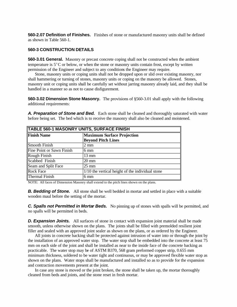
560-2.07 Definition of Finishes. Finishes of stone or manufactured masonry units shall be defined as shown in Table 560-1. 560-3 CONSTRUCTION DETAILS 560-3.01 General. Masonry or precast concrete coping shall not be constructed when the ambient temperature is 5EC or below, or when the stone or masonry units contain frost, except by written permission of the Engineer and subject to any conditions the Engineer may require. Stone, masonry units or coping units shall not be dropped upon or slid over existing masonry, nor shall hammering or turning of stones, masonry units or coping on the masonry be allowed. Stones, masonry unit or coping units shall be carefully set without jarring masonry already laid, and they shall be handled in a manner so as not to cause disfigurement. 560-3.02 Dimension Stone Masonry. The provisions of §560-3.01 shall apply with the following additional requirements: A. Preparation of Stone and Bed. Each stone shall be cleaned and thoroughly saturated with water before being set. The bed which is to receive the masonry shall also be cleaned and moistened. TABLE 560-1 MASONRY UNITS, SURFACE FINISH Finish Name Maximum Surface Projection
Beyond Pitch Lines Smooth Finish 2 mm Fine Point or Sawn Finish 6 mm Rough Finish 13 mm Scabbed Finish 20 mm Seam and Split Face 25 mm Rock Face 1/10 the vertical height of the individual stone Thermal Finish 6 mm NOTE: All faces of Dimension Masonry shall extend to the pitch lines shown on the plans. B. Bedding of Stone. All stone shall be well bedded in mortar and settled in place with a suitable wooden maul before the setting of the mortar. C. Spalls not Permitted in Mortar Beds. No pinning up of stones with spalls will be permitted, and no spalls will be permitted in beds. D. Expansion Joints. All surfaces of stone in contact with expansion joint material shall be made smooth, unless otherwise shown on the plans. The joints shall be filled with premolded resilient joint filler and sealed with an approved joint sealer as shown on the plans, or as ordered by the Engineer. All joints in concrete backing shall be protected against intrusion of water into or through the joint by the installation of an approved water stop. The water stop shall be embedded into the concrete at least 75 mm on each side of the joint and shall be installed as near to the inside face of the concrete backing as practicable. The water stop may be of ASTM B370, 568 gram preformed copper strip, 0.655 mm minimum thickness, soldered to be water tight and continuous, or may be approved flexible water stop as shown on the plans. Water stops shall be manufactured and installed so as to provide for the expansion and contraction movements present at the joint. In case any stone is moved or the joint broken, the stone shall be taken up, the mortar thoroughly cleaned from beds and joints, and the stone reset in fresh mortar.

Joints shall not be filled by pouring in a thin or liquid mortar. E. Pointing (new construction) and Tuck Pointing (raking out and repointing). 1. Pointing. Tool the face joints with a pointing tool before the mortar sets, as approved by the Engineer. Avoid smearing the masonry surfaces with excess mortar forced out of the joints. For joints not pointed when the masonry is laid, prepare the joints for pointing by following the tuck pointing procedures. There will be no separate payment for this work. 2. Tuck Pointing (Repointing). Repoint the joints in masonry where indicated on the Contract plans or directed by the Engineer. Use an Item 705-21 Type M, S or N masonry or mortar cement ; “,” Errata tuck pointing mortar (or a specially designed one) with the same or weaker strength than the original mortar, as approved by the Engineer. Remove soft, loose, cracked and deteriorated mortar to a minimum depth (measured from the wall face) of twice the average joint width, and remove all deteriorated mortar beyond the minimum depth, as ordered by the Engineer. Do not damage the masonry during the removal process. Clean all contamination from the prepared joints. Prior to repointing, flush with water and leave all surfaces to be re-mortared in a dampened, surface dry state. Pack the prepared joints in layers with mortar that closely matches the original color and texture, allowing each layer to become thumb-print hard before the next. Use at least two layers when the joint depth is twice the joint width. Apply a final layer thickness that does not exceed the joint width. When the final layer is thumb-print hard, finish with a pointing tool that recreates the original joint shape, or as approved by the Engineer. Perform pointing when the ambient temperature is 5EC or above, and the masonry is frost free. Avoid recessed joints that hold water. After the mortar sets, clean all mortar and cement stains from other surfaces. In direct sunlight, keep the newly pointed masonry moist for at least 3 days. In shade, moisten 2 to 3 times a day for at least 3 days. F. Drawings. The contract plans show the general character of the masonry. Prior to the beginning of any work, the Contractor shall prepare and submit for the approval of the Regional Director, three sets of detail plans for all dimension masonry shown on the plans. The Contractor shall carefully check and assume full responsibility for the accuracy of this work. These detail plans will be examined and either approved or returned without approval to the Contractor, who shall check the indicated corrections and resubmit two sets of prints of revised details. When the detail plans have been approved, the Contractor shall furnish the Regional Director with three sets, one of which shall be reproducible. The drawings shall conform to the size and type of requirements for Shop Drawings set forth in the New York State Steel Construction Manual. 560-3.03 Split Faced Concrete Masonry. The provisions of §560-3.01 shall apply with the following additional requirements: A. Sample Wall. The Contractor shall construct a split faced concrete masonry wall 2 m long and 1.2 m high of approved units and matching mortar at a location designated. This procedure shall be repeated until a sample wall is approved by the Engineer. The approved sample wall shall be maintained intact until the Engineer directs its removal. In lieu of the field sample wall, the Contractor may show, for approval, a building constructed with units of the same type, color, texture and surface finish required. The field sample wall shall be required if the building masonry is not approved.
Upon approval of the sample wall or building, the Contractor shall furnish and lay split masonry to conform with the approved sample wall. B. Protection and Handling. Split faced concrete masonry units shall be protected by a wrapping of 100 :m polyethylene, and shall be handled on pallets by mechanical means, or by hand or tongs. Dumping of the masonry units from trucks, wheel barrows or other conveyances is prohibited. Particular care shall be taken to protect all edges and the face of the masonry units. Distorted, laminated, checked or cracked masonry units will be rejected and removed from the site of construction. On delivery to the site, the masonry units shall be neatly piled off the ground, on pallets or other approved implements, and protected from moisture by wrapping them with 100 :m polyethylene. Masonry units which become wet, shall not be laid in the wall until their conformance with the specifications for §704-10 is shown by tests. The cost of these tests shall be borne by the Contractor. C. Laying. The split faced concrete masonry shall be laid up, in the pattern shown on the plans, by skilled masons and in a first-class manner. The masonry shall be laid true to line and grade in level horizontal beds and be properly anchored. Each masonry unit shall be laid in a full mortar bed and in a manner to form a full end joint in one operation. The space between the split face masonry and the supporting concrete shall be filled with mortar and rodded until the mortar rises to the top of the masonry unit as each unit is placed. D. Bonding. The split faced concrete masonry shall be bonded to the supporting concrete. Dovetail anchors shall be continuous, set vertically and spaced on centers not exceeding 300 mm on the concrete walls. Ties shall be installed in the anchor slots at a maximum vertical height of 300 mm on centers. E. Joints. Joints in the exposed face shall be struck with a concave jointing unless otherwise specified. The joints shall be 10 mm wide and the concave jointing shall be 3 mm deep at the center. F. Protection Against Weather. The split faced concrete masonry shall be protected against the action of the weather. The tops and at least 600 mm down the sides of all walls not completed shall be constantly protected with suitable waterproof covering properly secured in place during periods of suspended work. The facing shall be so protected until it has been bonded to the concrete wall and completely sealed against moisture. During hot dry weather, the masonry shall be protected from the sun and kept moist for at least three days after completion. G. Protection Against Damage. Projections and angles exposed to damage shall be boxed or otherwise protected to prevent damage. Any units damaged during the progress of the work shall be replaced with new units at the Contractor's expense. H. Cleaning of Exposed Faces of Mortar and Drippings. Exposed faces of split faced concrete masonry units shall be cleaned free of excess mortar and mortar drippings, as the work progresses, to prevent excessive rubbing dur ing final cleaning operations. I. Expansion and Contraction Joints. Expansion and contraction joints shall be constructed as shown on the plans. The surfaces of the joints shall be plumb, true to line and smooth to the caulking compound. J. Final Cleaning. After the completion of adjacent work likely to soil the masonry, the split faced concrete masonry shall be thoroughly cleaned, removing all dirt, dust, mortar, stains, etc. The concrete masonry shall be brushed, while dry, with stiff fiber brushes. If this brushing does not clean the masonry to the satisfaction of the Engineer, then the Contractor shall clean the facing with soap powder in clean water applied with stiff fiber scrub brushes. After scrubbing with soap and water the Contractor shall

rinse the masonry with clean water. The Contractor may, with the Engineer's approval, substitute a cleaning solution that will not harm the concrete or mortar joints. The cleaning operation shall in all cases start at the top and proceed downward. K. Caulking. When the split faced concrete masonry has received the final cleaning, all expansion and contraction joints shall be filled at least 25 mm deep with caulking compound. All surfaces to receive the caulking compound shall be clean, free of loose materials, dirt, dust, frost, moisture, oils, laitance or curing compounds and shall be primed with clear lacquer, shellac or the manufacturer's recommended primer after the surfaces have been cleaned. A bond breaker shall be used as a release material back of the caulking compound. The bond breaker may be polyethylene, specially treated bond inhibiting pressure sensitive tape or any approved equal. The caulking compound shall be tooled with a concave joint finishing tool to provide a neat smoothly finished joint of uniform width. Where solvents are required on the jointing tool, they shall be as recommended by the manufacturer of the caulking compound. 560-3.04 Stone Masonry. The construction provisions of §560-3.02 shall apply. The individual stones shall be trimmed, recut and dressed, as may be necessary at the site, to obtain a pattern in the finished wall which will be in character with the requirements of drawings, specifications and the approved sample wall. The following general requirements will apply to the placing of stone masonry: A. Cross-Joints, Steps or Ladders. There shall be no cross-joints, steps or ladders. B. Subdivision of Rectangles. There shall be no subdivision of rectangles. C. Stone Shapes. There shall be no unusually shaped stone. D. Clusters. There shall be no clusters of stone of the same length and height. E. Horizontal Joint Length. There shall be no continuous horizontal joint greater in length than 3 meters. F. Vertical Joints. There shall be no more than five stones abutting any one vertical joint. G. Stone Proportions. There shall be no stone longer than six times its height nor shorter than one and one half times its height. The length of the average stone shall be three to five times its height. H. Horizontal Joints. Horizontal joints shall not have a slope varying from the horizontal by more than one percent. I. Color. Where stone masonry and dimension masonry are specified, for the same structure or in close proximity to each other, there shall be no great contrast in size or color between the Stone Masonry and the Dimension Masonry. Prior to beginning the work the Contractor shall lay up a sample wall conforming to the requirements of §560-3.03A except that the material details for the work shall conform to those for Stone Masonry. 560-3.05 Rubble Stone Masonry. The provision of §560-3.01 shall apply with the following additional requirements: The stone shall be laid to form substantial masonry presenting a neat, finished appearance. The minimum size of stone to be used shall be 100 mm in depth or rise, 230 mm in width, and 300 mm long. Spalls and pinners will not be allowed to show on the face of the work and shall be used otherwise only
where necessary. All stones shall be soundly and completely bedded in the mortar. The length of stretchers shall not exceed three times their rise, and the width of stretchers shall in no case be less than one and one-half times their rise. At least one-fourth of the stones in the face shall be headers and shall be evenly distributed. The length of headers shall be not less than 810 mm nor more than the thickness of the wall, where the work is 1.2 m or less in thickness. Where the work is more than 1.2 m thick, the length of headers shall be not less than 810 mm. The width of headers shall be not less than their rise. All stones shall be laid to break joints 150 mm or more and to thoroughly bond the work. No joint in the face shall be over 25 mm in width. Backing shall be good-sized, well-shaped stones so laid as to break joints. Spaces between stones shall be filled with spalls set in mortar. The degree of roughness of exposed faces shall be measured with a two meter straight edge supported between adjacent projections on the stone face. Variations in the stone face, in excess of 100 mm, measured from the straight edge to the extreme depression in stone or mortar will not be permitted. Rear faces shall present approximately plane surfaces. Pointing shall conform to the requirements of §560-3.02E. 560-3.06 Rubble Stone Masonry Laid Dry. The specifications of §560-3.05, Rubble Stone Masonry, shall apply except that no mortar shall be used and the requirements of §560-3.01 Construction Details (General), pertaining to frost shall not apply unless otherwise directed by the Engineer. 560-3.07 Precast Concrete Coping. The provisions of §560-3.02, Dimension Stone Masonry and §560-3.03, Split Faced Concrete Masonry, shall apply with exception of §560-3.02D, §560-3.03A, and §560-3.03D. 560-3.08 Tuck Pointing. Apply the provisions of §560-3.02E2 Tuck Pointing. For re-caulking work, rake out any old caulking to a minimum 25 mm depth and follow the provisions of §560-3.03K. Caulking. Do not damage masonry during the removal and cleaning process. 560-4 METHOD OF MEASUREMENT 560-4.01 Dimension Masonry. Dimension masonry will be measured as the number of square meters (including joints within the dimension masonry) measured on the plane of all the exposed surfaces of the dimension masonry incorporated in the work. 560-4.02 Split Faced Concrete Masonry. Split faced concrete masonry will be measured as the number of square meters (including joints within the masonry and between the split faced concrete masonry and the concrete wall, and the mortar bed for precast concrete coping), on the plane of all exposed surfaces of the masonry incorporated in the work. Split faced masonry below the finished surface of the ground or paving shall be considered as exposed in computing the area for payment. The approved, constructed, split faced concrete masonry sample wall will be paid for as split face concrete masonry. 560-4.03 Rubble Stone Masonry. Payment for rubble stone masonry will be made for the number of cubic meters within the payment lines shown on the plans and placed in accordance with the specifications. Concrete, mortar or any joint material within these payment lines will, for the purpose of payment, be classified as stone masonry and will not be paid for under any other item. 560-4.04 Stone Masonry. Payment for stone masonry will be made for the number of square meters (including joints within the stone masonry) measured on the plane of all the exposed surfaces of the stone masonry incorporated in the work. Mortar joints between concrete and stone masonry will be paid for as stone masonry.
Stone masonry shown on the plans below the finished grade or sidewalk (to prevent the possible exposure of unfaced concrete) shall be considered as exposed in computing the payment area for this item. 2.5 square meters will be used in payment for the complete accepted sample wall required in this specification. 560-4.05 (Vacant) 560-4.06 Precast Concrete Coping. The quantity to be paid for will be the number of meters of precast concrete coping (inc luding the joints between the coping units) placed in accordance with the plans, specification and orders of the Engineer. 560-4.07 Tuck Pointing. The Engineer will measure this work in the field as the number of square or linear meters of masonry pointed and cleaned, as bid. Linear measurements will be made along the joint centerline. 560-5 BASIS OF PAYMENT 560-5.01 Dimension Stone Masonry. The unit price bid per square meter shall include the cost of furnishing all labor, materials and equipment necessary to complete the work. Concrete, dimension masonry, mortar or any joint material within the nominal thickness of the dimension masonry will, for the purpose of payment, be classified as dimension masonry and will not be paid for under any other item. Projections, if any, into the concrete beyond the nominal thickness of dimension masonry will be paid for as the class of concrete displaced by the stone. No deduction will be made for railing post holes. Mortar Joints between Dimension Masonry and Concrete will be paid for as Dimension Masonry. Mortar Joints between Dimension Masonry and Stone Masonry will be paid for as Stone Masonry. 560-5.02 Split Faced Concrete Masonry. The unit price bid per square meter shall include the cost of furnishing all labor, materials (including anchors, ties, premolded bituminous joint material, and caulking compound) and equipment necessary to complete the work. The payment shall also include the labor, materials and equipment necessary to remove and dispose of all constructed sample masonry panels when directed by the Engineer. No payment shall be made to the Contractor for the submitted alternate sample walls or for any unapproved sample walls. The cost of furnishing and placing anchoring devices shall be included in the unit price bid for this work. The cost of erecting and disposing the sample wall shall be included in the unit price bid for this item. 560-5.03 Stone Masonry. The unit price bid per square meter shall include the cost of furnishing all labor, materials and equipment necessary to complete the work. Concrete, stone masonry, mortar or any joint material within the nominal thickness of the stone masonry will, for the purpose of payment, be classified as stone masonry and will not be paid for under any other item. Projections, if any, into the concrete beyond the nominal thickness of stone masonry will be paid for as the class of concrete displaced by the stone. No deduction will be made for railing post holes. The cost of furnishing and placing anchoring devices shall be included in the unit price for this item. 560-5.05 Rubble Stone Masonry. The unit price bid per cubic meter for Rubble Stone Masonry with joints or laid dry, shall include the cost of furnishing all labor, materials and equipment necessary to complete the work except excavation will be paid for under the appropriate excavation item.

560-5.06 Precast Concrete Coping. The unit price bid per meter shall include the cost of furnishing all labor, materials (including anchors, reinforcement, premolded resilient joint materials, and caulking compound) and equipment necessary to complete the work. 560-5.07 Tuck Pointing. Include all labor, material (including any re-caulking material), and equipment to complete the work in the unit bid price. 560-5.08 Progress Payments. Progress payments will be made, at the unit price bid, for 75% of the quantity properly placed. The balance of the quantity will be paid for upon proper cleaning and caulking of the joints. Payment will be made under: Item No. Item Pay Unit 560.01 M Dimension Stone Masonry Square Meter 560.02 M Split Faced Concrete Masonry Square Meter 560.0401 M Stone Masonry Square Meter 560.05 M Rubble Stone Masonry Cubic Meter 560.06 M Rubble Stone Masonry Laid Dry Cubic Meter 560.07 M Precast Concrete Coping Meter 560.08 M Tuck Pointing Meter 560.09 M Tuck Pointing Square Meter SECTION 563 - PRESTRESSED CONCRETE UNITS (STRUCTURAL) 563-1 DESCRIPTION. This work shall consist of furnishing and placing prestressed concrete units for structures, as specified in the contract documents. 563-2 MATERIALS 563-2.01 Prestressed Units. The Contractor shall notify the D.C.E.S. of the source of prestressed units, for approval within (7) days after the award of the contract. Prestressed concrete units shall meet the requirements of the P.C.C.M. 563-2.02 Transverse Tie Rods or Strands. Refer to P.C.C.M., Section 4. 563-2.03 Shear Key Material. Refer to P.C.C.M., Section 4. 563-2.04 Anchorage Block-Out Grout. Refer to P.C.C.M., Section 4. 563-3 CONSTRUCTION DETAILS. The requirements of the P.C.C.M. shall apply. 563-4 METHOD OF MEASUREMENT 563-4.01 Prestressed Concrete I-Beam Units. The quantity to be paid for under this work shall be the number of meters (horizontal length center-to-center of bearings or anchor dowels, as shown on the plans) of each unit furnished and placed in accordance with the plans and specifications. 563-4.02 Prestressed Concrete Box-Beam Units and Hollow and Solid Slab Units. The quantity to be paid for under this work shall be the number of square meters of plan area of each prestressed unit installed. Plan area is defined as the area bounded by the centerline of bearings and the

outer edges of each prestressed unit. No deductions will be made for chamfers, shear keys, or notch cuts. Space between the units shall not be included in any measurement. 563-5 BASIS OF PAYMENT. The unit price bid for these units shall include all labor, materials and equipment necessary to complete the work except that bearings shall be paid for under their respective items. Damaged units which cannot be satisfactorily repaired or which do not meet dimensional and camber tolerances shall be replaced by the Contractor at no cost to the State. Progress payments will be made when each unit is furnished and placed in accordance with the plans and specifications exclusive of preparing and filling joints. Payment will be made at the unit price bid for 90% of the quantity properly placed. The balance of the quantity will be paid for upon completion of the work. The completion of work will include the correct preparation and filling of the joints as well as the tightening of transverse ties. Payment will be made under: Item No. Item Pay Unit 563.010X M Prestressed Concrete I-Beam Units (Types 1-6) Meter 563.02 M Prestressed Concrete Box Beam Units Square Meter 563.03 M Prestressed Concrete Hollow Slab Units Square Meter 563.04 M Prestressed Concrete Solid Slab Units Square Meter X = Type Designation (1 through 6) SECTION 564 - STRUCTURAL STEEL 564-1 DESCRIPTION. Under this work, the Contractor shall fabricate, furnish and erect structural steel and other metal parts as shown on the plans and in accordance with the provisions of the contract documents. The Contractor's attention is directed to §106-01, Source of Supply and Quality Requirements, with regard to advising Departmental Representatives of the sources of proposed materials. 564-2 MATERIALS. Materials for this work shall meet the requirements of the New York State Steel Construction Manual and the following subsections of §700 - Materials: Paint as Specified 708 Structural Steel 715-01 High Strength Bolts, Nuts and Washers 715-14 Pins and Rollers 715-15 Vertical Load Transmitting Devices 728 Painting Procedures 740 Certified copies of the results of tests conducted by the manufacturer shall be furnished to the Engineer in accordance with the requirements of §715-01, Structural Steel. 564-2.01 Structural Steel Replacement - Stock Steel Option. Stock steel may be furnished for this work. If furnished, the stock steel shall comply with the provisions of §715-01, Structural Steel. Positive heat identification will be required for all stock steel. Certified copies of the results of chemical analysis and physical tests shall be furnished to the Department. Shop inspection will be provided unless otherwise noted on the contract plans, or waived by the D.C.E.S. The provisions of this subsection shall apply only to pay items entitled “Structural Steel Replacement (kg.)” or “Structural Steel Replacement (Each).”

564-3 CONSTRUCTION DETAILS. All structural steel work, including, but not limited to fabrication inspection, transportation, and erection shall be done in accordance with the provisions of the SCM. Shop drawings prepared for pay items titled Structural Steel Replacement (Kg.) and Structural Steel Replacement (Each) shall be prepared, approved and distributed in accordance with the provisions of the SCM, except that the term “D.C.E.S.” shall be interpreted as “the Engineer.” 564-4 METHOD OF MEASUREMENT. Measurement will be made by one, or combinations of the following methods as indicated in the contract documents. ! Kilogram
! Each
! Lump Sum
564-4.01 Kilogram. Measurement will be made on a kilogram basis. The mass of each shipping unit shall be clearly shown on the approved shop drawings. For the purpose of measurement, such items as castings, anchor bolts, forgings, fasteners, cable and other metal parts used in the construction shall, unless otherwise provided, be considered to be structural steel even if made of other materials. A. Payment Mass. Payment will be based on the computed mass of metal as shown on the approved shop drawings, and shall include permanent bolts and welds in the structure as erected. The mass of all erection materials including but not limited to bolts, pilot and driving nuts, temporary protective coatings, and all boxes, crates or other containers used for packing, together with sills, struts, and rods used for supporting members during transportation, shall be excluded. The mass of all required bolt heads, nuts and washers will be estimated, making no allowance for waste, and included in the mass for which payment will be made. The mass of all required welds will be estimated and included in the mass for which payment will be made. B. Computed Mass. The mass of steel shall be assumed as 7850 kg/m3. The mass of cast iron shall be assumed as 7210 kg/m3. The masses of rolled shapes and of plates of all dimensions shall be computed on the basis of their nominal masses as required by the dimensions shown on the approved shop drawings. If the Contractor, however, elects to use for his convenience, steel members with masses that are greater than the nominal masses specified on the approved drawings, the computations shall be based on the nominal mass values on the drawings. Deductions shall be made for copes, cuts and all holes except those holes required for high-strength bolts. The mass of fillet welds shall be computed from the following: TABLE 564-1 MASS OF DEPOSITED METAL PER METER OF FILLET WELD Size of Fillet (mm) 5 6 8 10 12 16 20 Deposited Metal (kg/m) 0.139 0.200 0.365 0.516 0.705 1.088 1.747
The masses of castings shall be computed from the dimensions shown on the approved shop drawings, with an addition of 10% for fillets and overrun. The mass of high-strength bolts, nuts and washers, exclusive of grip, shall be computed from the following: TABLE 564-2 MASSES OF HIGH-STRENGTH BOLTS Bolt Diameter (mm) 13 16 20 22 24 27 30 36
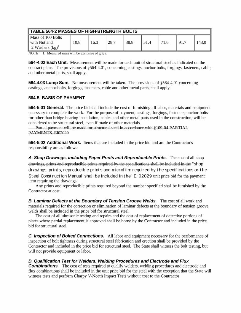
TABLE 564-2 MASSES OF HIGH-STRENGTH BOLTS Mass of 100 Bolts with Nut and 2 Washers (kg)1
10.8
16.3
28.7
38.8
51.4
71.6
91.7
143.0
NOTE 1. Measured mass will be exclusive of grips. 564-4.02 Each Unit. Measurement will be made for each unit of structural steel as indicated on the contract plans. The provisions of §564-4.01, concerning castings, anchor bolts, forgings, fasteners, cable, and other metal parts, shall apply. 564.4.03 Lump Sum. No measurement will be taken. The provisions of §564-4.01 concerning castings, anchor bolts, forgings, fasteners, cable and other metal parts, shall apply. 564-5 BASIS OF PAYMENT 564-5.01 General. The price bid shall include the cost of furnishing all labor, materials and equipment necessary to complete the work. For the purpose of payment, castings, forgings, fasteners, anchor bolts for other than bridge bearing installation, cables and other metal parts used in the construction, will be considered to be structural steel, even if made of other materials. Partial payment will be made for structural steel in accordance with §109-04 PARTIAL PAYMENTS. EI02029 564-5.02 Additional Work. Items that are included in the price bid and are the Contractor's responsibility are as follows: A. Shop Drawings, including Paper Prints and Reproducible Prints. The cost of all shop drawings, prints and reproducible prints required by the specifications shall be included in the “shop drawings, prints, reproducible prints and microfilm required by the specifications or the Steel Construction Manual shall be included in the” EI02029 unit price bid for the payment item requiring the drawings. Any prints and reproducible prints required beyond the number specified shall be furnished by the Contractor at cost. B. Laminar Defects at the Boundary of Tension Groove Welds. The cost of all work and materials required for the correction or elimination of laminar defects at the boundary of tension groove welds shall be included in the price bid for structural steel. The cost of all ultrasonic testing and repairs and the cost of replacement of defective portions of plates where partial replacement is approved shall be borne by the Contractor and included in the price bid for structural steel. C. Inspection of Bolted Connections. All labor and equipment necessary for the performance of inspection of bolt tightness during structural steel fabrication and erection shall be provided by the Contractor and included in the price bid for structural steel. The State shall witness the bolt testing, but will not provide equipment or labor. D. Qualification Test for Welders, Welding Procedures and Electrode and Flux Combinations. The cost of tests required to qualify welders, welding procedures and electrode and flux combinations shall be included in the unit price bid for the steel with the exception that the State will witness tests and perform Charpy V-Notch Impact Tests without cost to the Contractor.

E. Radiographic Inspection. The cost of radiographic inspection and of preparation for radiography, together with the cost of providing access and of furnishing adequate facilities for the review of radiographs in the shop or field, shall be included in the price bid for structural steel. F. Ultrasonic Inspection. Ultrasonic inspection, when required, will be performed by the State or its representatives unless otherwise provided for in the contract documents. The cost of any required preparation and of furnishing access to the joints shall be included in the price bid for structural steel. G. Magnetic Particle Inspection. The cost of magnetic particle inspection when specified or required by the inspector to verify limits of defects discovered during visual inspection shall be included in the unit price bid for structural steel. H. Repair of Defects in Welds and Base Metal. The cost of repairing defects found by visual inspection or nondestructive tests shall be included in the unit price bid for structural steel. I. Field Inspection of Rejected Material or Material Not Offered for Shop Inspection even though Required to be Shop Inspected by the Contract Documents. When the Department, at its discretion, permits inspection of the subject materials to be performed at the project site, all costs of this inspection shall be borne by the Contractor as a condition of the Department's approval of inspection of this material. All costs associated with the inspection of rejected material, which has been shipped to the field without approval, shall be borne by the Contractor. J. Straightening Bent Material and Correcting Camber Deficiencies. All corrective work required to straighten bent material and correct camber deficiencies, when permitted, shall be performed at no additional cost to the State. K. Field Repair, Reaming and Drifting of Holes. All work permitted for the correction of unacceptable holes shall be provided at the Contractor's expense. L. Metal Scuppers. Metal scuppers shall be paid for as structural steel unless otherwise noted on the plans. M. Adjustment and Alignment of Bearings. All labor, materials and equipment required for adjustment and alignment of bearings shall be included in the unit price bid for structural steel. N. Field Splices. When the specific location for a bolted or welded field splice in stringers and girders is not shown on the plans, the Contractor will be permitted to introduce splices at locations of his choice. The splices shall be made in accordance with the provisions of the SCM. No payment will be made for labor, material, and equipment required to make a splice if the splice is not shown on the contract plans. Also, payment will not be made for increases in the thickness of webs or flanges made necessary by the requested splice. O. Photographs. Photographs requested by the D.C.E.S. in accordance with the provisions of the SCM, shall be furnished at no additional cost. P. Testing of Stock Steel. All labor, materials and equipment necessary to perform chemical and physical tests on stock steel when such tests are required shall be furnished by the Contractor and included in the price bid for structural steel.

Q. Heat-Curving and Cambering. All costs of nondestructive testing, repairs or replacement of material damaged due to over stressing or destructive heating during heat-curving or cambering shall be borne by the Contractor. “564-5.03 Progress Payments for Fabricated Steel. Upon application by the contractor, payments for some of the cost of fabricated steel will be made to the contractor prior to shipping and incorporation of such material in the permanent work, subject to the following: A. To be eligible for progress payment, the steel must meet all of the following conditions: 1.Include all the structural steel required for one or more spans of the bridge. If stage construction of the bridge is required by the Contract this will be interpreted as all the steel required for one or more stages of one or more spans of the bridge. The mass of steel extending beyond the end of the span to a splice point will be included for payment. 2.Have a minimum mass of 10,000 kg. 3.Be materials which will be incorporated into permanent work. 4.A. For unpainted (weathering) steel, be in a condition which is ready for on-site installation without further fabrication. B.For steel that will be coated or painted, be completely fabricated, inspected and ready for shipment to a coating shop. B.With application for progress payments, the contractor shall provide documentation as follows:
1. Bill of sale or vouchers indicating the actual dollar value paid by the contractor for the materials as stored; 2.Certification of Title showing that title to the materials, without encumbrances, is in the name of the contractor and that title is warranted to the Department of Transportation; 3.Documented evidence of acceptability of the materials; 4.A release and waiver covering such materials, and providing access to the storage site, which release and waiver shall be executed by the property owner in favor of the New York State Department of Transportation or its agents.
C.For rolled beam and plate girder bridges, the amount of progress payments shall not exceed the total invoice amount for stored materials, nor shall the partial payment exceed eighty five percent (85%) of the pro rata value of the lump sum bid. The pro rata values shall be calculated by multiplying the lump sum price bid by
the ratio which represents the structural steel members fabricated and stored during the payment period in question. The ratio will be computed by dividing the mass of the steel by the Total Mass for Progress Payments for the appropriate item. See §564-5.04. D.For truss bridges, arches, or other construction identified in the Contract Documents, the amount of progress payments shall not exceed the total invoice amount for stored materials, nor shall the partial payment exceed seventy five percent (75%) of the pro rata value of the lump sum bid. The pro rata values shall be calculated by multiplying the lump sum price bid by the ratio which represents the structural steel members fabricated and stored during the payment period in question. The ratio will be computed by dividing the mass of the steel by the Total Mass for Progress Payments for the appropriate item. See §564-5.04. E.When progress payments are made in accordance with this subsection, no application for payment in accordance with §109-04 PARTIAL PAYMENTS will be considered by the Department.
The making of progress payments shall not be deemed to be a final acceptance of materials, nor shall it relieve the contractor of responsibility for such materials. The contractor shall be responsible for assuring that only those materials which comply with the specifications are incorporated into the project.” EI02029 564-5.03 564-5.04 EI02029 Progress Payments - Lump Sum. These shall be calculated by multiplying the lump sum price bid by the ratio which represents the structural steel members erected during the payment period in question “and then subtracting any partial and progress payments made according to §109-04 and §564-5.03.” EI02029 (Refer to §109-03). The ratio will be computed by dividing the shipping mass of the erected steel (obtained from the Report of Shipment of Structural Material, Form B & GC-4b) by the Total Mass for Progress Payments for the appropriate item. “The Total Mass for Progress Payments” will be indicated on the plans for use in determining Partial Payments and Progress Payments. Under no circumstances will the “Total Mass for Progress Payments” be used for final payment purposes. The Contractor is advised not to use the “Total Mass for Progress Payments” as a bidding tool. Discrepancies which may occur between the total mass shipped and the “Total Mass for Progress Payments”, as indicated on the plans, will not be a basis for additional compensation. 564-5.04 564-5.05 EI02029 Other Work. Work not included in the unit price bid for the structural steel item is as follows: A. Setting Anchor Bolts for Bridge Bearings. The pipe sleeves, anchor bolts and work required to furnish, set and grout the anchor bolts, shall be included in the price bid for the respective bearing item. B. Vertical Load Transmitting Devices. The furnishing and installing of vertical load transmitting devices, such as; rubber impregnated random fiber pad, and plain rubber pad, shall be included in the price bid for the respective item. Payment will be made under: Item No. Item Pay Unit 564.05XX M Structural Steel (Type 1-16) “(Type 1-22)” Errata Lump Sum
564.10nn”nn” M Structural Steel Replacement Kilogram 564.51nn”nn” M Structural Steel Kilogram 564.70nn”nn” Errata M Structural Steel Replacement Each NOTE: nn denotes serialized pay item, see §101-02 Definitions of Terms under "Specifications". SECTION 565 - BRIDGE BEARINGS 565-1 DESCRIPTION. The work shall consist of furnishing, placing and setting bridge bearings at the locations indicated on the plans. 565-1.01 Bearing Types. There are various types of bearings. The specific type required will be indicated on the plans. Bearing types are: A. Type S.R. - Steel Rocker Bearings. These accommodate rotation by pivoting around a pinned joint. They are fabricated in fixed and expansion versions. The expansion version accommodates longitudinal movement by means of a curved rocker rotating on the bearing surface. Steel rocker bearings do not allow for transverse movement. This type of bearing shall only be used in rehabilitation situations where only one or two bearings are to be replaced on a bridge. B. Type S.S. - Steel Sliding Bearings. These accommodate rotation by means of a rocker. They are fabricated in fixed and expansion versions. The expansion version accommodates movement with a sliding element. Steel sliding bearings do not allow for transverse movement. This type of bearing shall only be used in rehabilitation situations where only one or two bearings are to be replaced on a bridge. C. Type M.R. - Multi-Rotational Bearings. These accommodate rotation by the deformation of a confined elastomeric element, or an unconfined urethane disc. Multi-rotational bearings are fabricated in fixed and expansion versions. The expansion version accommodates movement by means of sliding elements. Expansion versions may be guided, allowing movement in only one direction, or non-guided, allowing multi-directional movement. D. Type E.P. - Plain Elastomeric Bearings. These accommodate rotation by the deformation of a plain elastomeric pad. They may be used for both fixed and expansion applications without changes in details. The bearings will accommodate longitudinal, transverse, and rotational movements. E. Type E.L. - Steel Laminated Elastomeric Bearings. These accommodate rotation by the deformation of a laminated elastomeric and steel pad. They may be used for both fixed and expansion applications without changes in details. The bearings will accommodate longitudinal, transverse, and rotational movements. F. Type E.B. - Elastomeric Bearings with External Load Plates. These accommodate rotation by the deformation of a plain or steel laminated elastomeric pad. Elastomeric bearings with external load plates are fabricated in fixed and expansion versions. The fixed version will accommodate rotational movements. The expansion bearings will accommodate longitudinal, transverse, and rotational movements. 565-2 MATERIALS 565-2.01 General. Materials shall meet the following requirements: Concrete Grouting Material 701-05

Plain Elastomeric Bridge Bearings 716-10 Steel Laminated Elastomeric Bridge Bearings 716-11 Cap Screws ASTM F835M or A574M Elastomeric Bridge Bearings with External Load Plates 716-12 Disc Design Structural Bridge Bearings 716-06.01 Pot Design Structural Bridge Bearings 716-07.01 Anchor Bolts 723-60 Rubber Impregnated Woven Cotton Fabric 728-01 Rubber Impregnated Random Fiber Pad 728-02 Plain Rubber Pad 728-03 Steel Anchor Dowel 709-01a Paint Department Approval List - Paints for
Structural Steel Note a. Steel anchor dowels shall meet the requirements of §709-01 - Bar Reinforcement. 565-2.02 Fabrication. Steel components of bridge bearings shall be fabricated in accordance with the applicable requirements of the NYS Steel Construction Manual (SCM). In addition, component parts of individual bearings shall meet fabrication details as shown in the contract documents. A. Type S.R. Bearings. These shall conform to the plans and other contract documents. B. Type S.S. Bearings. These shall conform to the plans and other contract documents. C. Type M.R. Bearings. These shall conform to the requirements of either §716-06.01 or §716-07.01 as applicable, and other contract documents. When type M.R. bearings are specified, the Contractor may supply either disc design or pot design bearings. Only one bearing design, disc or pot, shall be supplied for any one bridge. D. Type E.P. Bearings. These shall conform to the requirements of §716-10 and other contract documents. E. Type E.L. Bearings. These shall conform to the requirements of §716-11 and other contract documents. F. Type E.B. Bearings. These shall conform to the requirements of §716-12 and other contract documents. 565-2.03 Drawings. Shop drawings shall meet the requirements specified in the following: Type S.R. and S.S. Bearings SCM, Section 2 Type M.R. Bearings 716-06.01 or 717-07.01 Type E.L. Bearings 716-11 Type E.B. Bearings 716-12 565-2.04 Protective Coatings A. Machine finished surfaces in contact, including pins, pin holes, surfaces in sockets at the top of rocker bearings, and bronze or copper plates in sliding contact shall receive one coat of automotive grease as soon as machining is comple te. None of these surfaces shall be painted. B. Stainless steel and polytetrafluoroethylene surfaces shall not be painted or otherwise coated.

C. Metal to metal surfaces to be field welded shall be given a coat of clear lacquer or other protective coating approved by the Engineer, or Inspector, if exposure is to exceed three months prior to welding. The coating shall be removed at the time of welding. Painting, if required, will be done only after the completion of welding. Surfaces to be painted shall be primed and painted in accordance with §565-2.04D. D. All other metal surfaces shall be cleaned to meet SSPC-SP6, Surface Preparation Specification No. 6 Commercial Blast Cleaning, and painted with three coats of paint. The paint (primer, intermediate and finish coat) shall be selected from the Department's Approved List, Paints for Structural Steel. All coats of paint used shall be produced by the same manufacturer and be applied at a rate sufficient to produce a minimum dry film thickness of 75 :m per coat. Each single paint coat shall be a color different from others. For bearings used in conjunction with painted steel the color of the finish coat shall be the same color as the finish coat of the structural steel. For bearings used in conjunction with unpainted steel, the color of the finish coat shall be a rusty brown color which is a reasonable visual match to Federal Color Standard No. 595, Color 20059. 565-2.05 Shipping. Each bearing shall be shipped as an assembled unit, except for ela stomeric bearings. Elastomeric bearings may be shipped in packages containing more than one bearing, provided the package can be handled with normal construction equipment. Bearings shall be packaged in such a manner to protect all rotating and sliding surfaces from the intrusion of outside material. Type M.R. Bearings shall be shipped precompressed to 3.45 MPa. 565-3 CONSTRUCTION DETAILS 565-3.01 Concrete Bearing Surface Elevations A. General. The elevation of the concrete bearing surface for all types of bearings, except Type M.R. bearings, shall be as given on the plans. B. Type M.R. Bearings. The elevation of the concrete bearing surface may vary from that given on the plans depending on the vertical dimension of the actual bearing supplied. The Contractor shall notify the Engineer of all required elevation changes. Changes to the roadway profile will not be allowed. All elevation adjustments necessary to maintain the profile shall be made to the concrete bearing surfaces. Any adjustments, including changes to the reinforcement, will be made at no additional cost to the State. 565-3.02 Concrete Bearing Surface Preparation. No bearing shall be placed upon a concrete bearing surface which is deformed, irregular, or poorly finished. The entire bearing surface area shall be floated and troweled. 565-3.03 Setting Anchor Bolts. Anchor bolts shall be set as shown on the plans unless changes are permitted by the D.C.E.S. If anchor bolts are cast in substructure concrete, templates, or other suitable means, shall be used to keep the bolts vertical at the required embedment and in the correct horizontal position during concrete placement. If the Contractor elects to drill the finished, cured concrete in order to set the anchor bolts, the reinforcing steel shall be positioned prior to casting the concrete so that it will not be damaged during drilling. If anchor bolts are drilled and grouted, material and construction details shall be in conformance with §586-2 and §586-3. 565-3.04 Bearing Pad Installation. Bearing pads placed between concrete, or other masonry, and steel masonry plates shall be located to correct alignment and elevation, and placed at the time of masonry plate installation. Bearing pads shall conform to §728-01, §728-02, or §728-03 at the Contractor's option.

Each bearing pad shall be the same size in plan as the masonry plate it supports. Holes to accommodate anchor bolts shall be cleanly and accurately cut prior to bearing pad placement. 565-3.05 Bearing Installation and Alignment A. Type S.R. and Type S.S. Bearings 1. General a. The centerline of sole plates or fixed portions of bearing assemblies attached to the structural steel shall not be offset from the centerline of bearing stiffeners or diaphragm connection plates by more than one-half the thickness of the flange at that location, or the thickness of the bearing stiffener or connection plate, whichever is the lesser distance. b. The bearing shall be cleaned and regreased with automotive grease at the time of installation. 2. Fixed. No additional requirements apply. 3. Expansion. These may vary from perfect alignment. Therefore, expansion bearings shall be set in accordance with the following. a. Type S. R. Bearings (1) The bearing shall be set vertical under full dead load at an ambient temperature of 20EC. (2) The maximum variation from perfect alignment is a function of the bearing height. The bearing height is the distance between the upper and lower contact surfaces of the movable portion of the bearing. For bearings with a height of 510 mm or less, the maximum variation from perfect alignment, taking into account the effect of temperature and load at the time of measurement, shall be calculated by the following formula: M = ? " (13 mm + (L/356,000 ) ) where “M” = maximum variation from perfect alignment measured as the horizontal distance between the centerline of the cap plate and the centerline of the masonry plate in millimeters and “L” = total expansion length in millimeters between the centerline of the movable bearing being considered and the centerline of the fixed bearing, from which motion must progress. Such variations shall not exceed 25 mm offset, or a five degree rotation of the movable portion of the bearings from the required alignment, whichever is less. The maximum variation of all bearings having a height exceeding 510 mm shall be approved on an individual basis by the D.C.E.S. (3) No bearing adjustments shall be made until the completed structural slab has been in place for at least seven curing days. Any adjustments needed to meet the above requirements may require jacking the superstructure. All adjustments shall be accomplished according to a written procedure submitted by the Contractor for D.C.E.S. approval. All adjustments shall be made at no additional cost to the State. b. Type S. S. Bearings (1) The sliding plate shall be centered on the masonry plate under full dead load at an ambient temperature of 20EC.

(2) The maximum variation from perfect alignment between the centerlines of the fixed and movable portions of the bearing device, taking into account the effect of temperature and load at the time of measurement, shall not exceed plus or minus 13 mm longitudinally. This variation shall be measured as the horizontal distance between the centerline of the sliding plate and the centerline of the masonry plate. The movable portion of the bearing device shall be fully supported by the fixed portion under all temperature and loading conditions. (3) No bearing adjustments shall be made until the completed structural slab has been in place for at least seven curing days. Any adjustments needed to meet the above requirements may require jacking the superstructure. All adjustments shall be accomplished according to a written procedure submitted by the Contractor for D.C.E.S. approval. All adjustments shall be made at no additional cost to the State. B. Type M.R. Bearings 1. General. The centerline of sole plates or other fixed portions of bearing assemblies attached to the structural steel shall not be offset from the centerline of bearing stiffeners or diaphragm connection plates by more than one-half the thickness of the flange at that location, or the thickness of the bearing stiffener or connection plate, whichever is the lesser distance. 2. Fixed. No additional requirements apply. 3. Expansion. These may vary from perfect alignment. Therefore expansion bearings shall be set in accordance with the following: a. The sliding plate shall be centered on the masonry plate under full dead load at an ambient temperature of 20EC. b. The maximum variation from perfect alignment between the centerline of the fixed and movable portions of the bearing device, taking into account the effects of temperature and load at the time of measurement, shall not exceed plus or minus 25 mm longitudinally unless otherwise indicated on the plans. This variation shall be measured as the horizontal distance between the centerline of the sliding plate and the centerline of the masonry plate. c. No bearing adjustments shall be made until the completed structural slab has been in place for at least seven curing days. Any adjustments needed to meet the above requirements may require jacking the superstructure. All adjustments shall be accomplished according to a written procedure submitted by the Contractor for D.C.E.S. approval. All adjustments shall be made at no additional cost to the State. C. Type E.P. and Type E.L. Bearings 1. General a. These bearings are designed to function properly provided that minimum distortion occurs along the beam axis under full dead load at an ambient temperature of 20EC. Elastomeric bearings shall be installed when the ambient temperature is between 5E and 26E C inclusive. The Contractor may elect to install the bearings when the ambient temperature is outside of the allowable range, provided the Contractor submits, and receives D.C.E.S. approval, of an installation procedure that either resets the bearings when the temperature is in the allowable range or deforms the bearings so that they perform as if they were installed at 20EC. b. For prestressed concrete superstructures, the bearing shall be anchored to establish the fixed end of the bridge as soon as possible after stringer erection. For adjacent prestressed box beams, or prestressed slab superstructures, the anchorage shall be completed prior to filling the shear keys. The method of anchorage shall be in accordance with the details shown on the plans. Anchor dowel holes shall be core drilled to the nominal size and depth and at the locations required by the plans. In lieu of core drilling,
the Contractor may submit an installation procedure that incorporates the use of either preset anchor bolts or pipe sleeves to the D.C.E.S. for approval. Prior to placing the anchor dowel, the hole shall be inspected and approved for filling by the Engineer. Fill materia l shall be in accordance with the details on the plans. 2. Fixed. No additional requirements apply. 3. Expansion a. These may vary from perfect alignment. The maximum variation from perfect alignment under full dead load shall not exceed the value shown on the plans. This variation shall be measured as the horizontal distance between the centerline of the highest elastomer surface and the centerline of the lowest elastomer surface. b. No bearing adjustments shall be made until the completed structural slab has been in place for at least seven curing days. Any adjustments needed to meet the above requirements may require jacking the superstructure. All adjustments shall be accomplished according to a written procedure submitted by the Contractor for D.C.E.S. approval. All adjustments shall be made at no additional cost to the State. D. Type E.B. Bearings 1. General a. The centerline of sole plate or other fixed portions of bearing assemblies, attached to steel stringers, shall not be offset from the centerline of bearing stiffeners of diaphragm connection plates by more than one-half the thickness of the flange at that location, or the thickness of the bearing stiffener or connection plate, whichever is the lesser distance. b. These bearings are designed to function properly provided that minimal distortion occurs along the beam axis under full dead load at an ambient temperature of 20EC. Elastomeric bearings shall be installed when the ambient temperature is between 5E and 26E C inclusive. The Contractor may elect to install the bearings when the ambient temperature is outside of the allowable range, provided the Contractor submits, and receives D.C.E.S. approval, of an installation procedure that either resets the bearings when the temperature is in the allowable range or deforms the bearings so that they perform as if they were installed at 20EC. 2. Fixed. No additional requirements shall apply. 3. Expansion a. These may vary from perfect alignment. The maximum variation from perfect alignment under full dead load shall not exceed the value shown on the plans. This variation shall be measured as the horizontal distance between the centerline of the highest elastomer surface and the centerline of the lowest elastomer surface. b. No bearing adjustments shall be made until the completed structural slab has been in place for at least seven curing days. Any adjustments needed to meet the above requirements may require jacking the superstructure. All adjustments shall be accomplished according to a written procedure submitted by the Contractor for D.C.E.S. approval. All adjustments shall be made at no additional cost to the State. 565-3.06 WELDING A. Type S.R. Bearings. Bearings shall be welded permanently to the structural steel only after all necessary adjustments have been made. All welding shall be done in accordance with the requirements of

the SCM. The Contractor shall submit a Welding Procedure Specification to the D.C.E.S. No welding shall be performed until the manufacturer receives an approved Welding Procedure Specification. B. Type S.S. Bearings. The requirements of §565-3.06A shall apply. C. Type M.R. Bearings. The requirements of §565-3.06A shall apply except that during field welding operations the temperature of the steel adjacent to the rotational element shall not exceed 90EC. Temperature shall be controlled by welding procedures and monitored using temperature indicating crayons, or other devices. Procedures, crayons, and other devices shall be acceptable to the Engineer. If the temperature limit is exceeded, the D.C.E.S. and the Director, Materia ls Bureau shall be immediately notified. The D.C.E.S. will provide the proper repair procedure, which may include complete replacement of the bearing. All repair work shall be done at no additional cost to the State. D. Type E.B. Bearings. The requirements of §565-3.06A and §565-3.06C shall apply. 565-3.07 Grouting Anchor Bolt Holes. All slotted anchor bolt holes in masonry plates shall be filled with concrete grouting material to the top edge of the hole. All excess grout material shall be cleaned from the bearing surfaces in a manner satisfactory to the Engineer. Slotted anchor bolt holes in fixed bearings may be filled any time subsequent to stringer placement. Slotted holes in expansion bearings shall be filled only after all necessary bearing adjustments have been made. 565-3.08 Final Verification. Prior to final acceptance of the bridge, the Engineer will verify that all necessary adjustments have been made; that all steel bearings, or external load plates, are permanently welded or attached with cap screws to the superstructure steel as shown on the contract plans; that all slotted holes are completely filled with grout; that all anchor bolts are firmly tightened; and that all other work required to make the bearings completely functional has been completed. 565-4 METHOD OF MEASUREMENT. Measurement will be taken as the number of bearings installed in accordance with the Contract Documents. 565-5 BASIS OF PAYMENT. The unit price bid for each bearing shall include the cost of all labor, materials, equipment and adjustment necessary to complete the work. All material between the bottom of the superstructure, and the top of the substructure, including anchor bolts and sole plates, shall be included in the price bid for this item. 565-5.01 Progress Payments A. Type S.R. Bearings 1. Eighty percent of the quantity will be paid for after the bearing is installed. 2. The remainder of the quantity will be paid for after the bearing is aligned as required. B. Type S.S. Bearings. The requirements of §565-5.01A shall apply. C. Type M.R. Bearings. The requirements of §565-5.01A shall apply. Payment will be made under: Item No. Item Pay Unit 565.1121 M Type S.R. Expansion Bearing (All Load Ranges) Each 565.1221 M Type S.R. Fixed Bearing (All Load Ranges) Each
565.1321 M Type S.S. Expansion Bearing (All Load Ranges) Each 565.1421 M Type S.S. Fixed Bearing (All Load Ranges) Each 565.1521 M Type M.R. Expansion Bearing (0 to 1000 kN) Each 565.1522 M Type M.R. Expansion Bearing (1001 to 2000 kN) Each 565.1523 M Type M.R. Expansion Bearing (2001 to 3000 kN) Each 565.1524 M Type M.R. Expansion Bearing (3001 to 4000 kN) Each 565.1525 M Type M.R. Expansion Bearing (Over 4000 kN) Each 565.1721 M Type M.R. Fixed Bearing (0 to 1000 kN) Each 565.1722 M Type M.R. Fixed Bearing (1001 to 2000 kN) Each 565.1723 M Type M.R. Fixed Bearing (2001 to 3000 kN) Each 565.1724 M Type M.R. Fixed Bearing (3001 to 4000 kN) Each 565.1725 M Type M.R. Fixed Bearing (Over 4000 kN) Each 565.1821 M Type E.P. Bearing (All Load Ranges) Each 565.1921 M Type E.L. Bearing (0 to 250 kN) Each 565.1922 M Type E.L. Bearing (251 to 500 kN) Each 565.1923 M Type E.L. Bearing (501 to 750 kN) Each 565.1924 M Type E.L. Bearing (751 to 1000 kN) Each 565.1925 M Type E.L. Bearing (Over 1000 kN) Each 565.2021 M Type E.B. Fixed Bearing (0 to 250 kN) Each 565.2022 M Type E.B. Fixed Bearing (251 to 500 kN) Each 565.2023 M Type E.B. Fixed Bearing (501 to 750 kN) Each 565.2024 M Type E.B. Fixed Bearing (751 to 1000 kN) Each 565.2025 M Type E.B. Fixed Bearing (Over 1000 kN) Each 565.2031 M Type E.B. Expansion Bearing (0 to 250 kN) Each 565.2032 M Type E.B. Expansion Bearing (251 to 500 kN) Each 565.2033 M Type E.B. Expansion Bearing (501 to 750 kN) Each 565.2034 M Type E.B. Expansion Bearing (751 to 1000 kN) Each 565.2035 M Type E.B. Expansion Bearing (Over 1000 kN) Each SECTION 566 - MODULAR EXPANSION JOINT SYSTEMS 566-1 DESCRIPTION. The work shall consist of fabricating, furnishing, and installing a modular expansion joint system at the locations indicated on the Contract Plans. 566-1.01 Modular Joint Systems. Modular expansion joint systems are manufactured in various sizes, defined by their total movement capability. The correct movement capability required at any one location is indicated on the Contract Plans. 566-1.02 Sealing Elements. On each individual structure, all the box seals used in the modular joints shall be of the same configuration and shall be from the same manufacturer. 566-1.03 Modular Joint System Suppliers A. Multi-cell Modular Joint Systems. Only firms which appear on the Department’s Approved List will be acceptable suppliers. No supplier other than those listed will be considered. B. One Cell Modular Joint Systems. Firms that do not appear on the Department’s Approved List may supply one cell Modular Joint Systems. Firms which appear on the Department’s Approved List will also be acceptable suppliers. 566-1.04 Terminology. The following terminology will be used throughout this section:

A. Joint System. This term is used to describe the installation with all of its component parts as installed in the structure slab, and if applicable in sidewalks, barriers and other bridge components. B. Segment. A modular joint system manufactured at less than full roadway width. No segment shall be less than a single lane width long. C. Joint. The separation between two elements of a bridge to allow for movement. 566-2 MATERIALS. Materials shall conform to the following requirements. 566-2.01 Modular Joint System. The modular joint system and all its component parts, including stiffening plates and anchorages, shall be supplied by the Manufacturer. The Manufacturer shall certify that the following components meet the listed requirements: Hollow Beams, Steel Extrusions and Milled Steel Shapes ASTM A588M Box Seals 705-09a Strip Seal ASTM D2628b Adhesive 567-2.02A6 Stud Shear Connectors and Threaded Studs 709-05 Connecting and Sliding Plates - 10 mm Thickness ASTM A588M Parapet Cover Plates - 13 mm Thickness ASTM A36Mc
Notes: a. Shape approval by the Director of Materials is not required. Hardness, Type A Durometer shall be 60 + 5; ASTM Method D2240. A 1 meter sample of the seal shall be submitted for testing to the Materials Bureau. No splices shall be permitted in permanent seals for any reason whatsoever. b. Recovery test not required. c. Parapet Cover Plates shall be Galvanized in accordance with §719-01, Type I. 566-2.02 Shop Drawings A. Shop Drawings shall be required for any joint system supplied as part of this work. Shop Drawings shall be prepared and reviewed in accordance with the applicable provisions of the SCM and this Specification and submitted to the D.C.E.S. for approval. All Shop Drawings shall note the name and address of the Joint System Fabricator, including the actual location (address) where the fabrication will take place. B. The Modular Joint System Manufacturer's instructions for the proper installation of the joint system shall be entered on the Shop Drawings. Manufacturer's instructions shall include the proper width settings for various ambient temperatures. Shop Drawings which lack Manufacturer's installation instructions shall be returned without examination. C. Filler metal shall be qualified in accordance with Section 7 of the SCM. Welding Procedure Specifications (WPS) shall be submitted for approval to the DCES with the Shop Drawings for each combination of joint type and welding process shown on the Shop Drawings. Shop Drawing Approval shall be withheld until this requirement has been met. 566-2.03 Fabrication A. All steel fabrication (shop and field) shall be done in accordance with the requirements of the SCM. Mill inspection of the steel will not be required.
B. All metal surfaces to come in contact with the neoprene sealer shall be blast cleaned in accordance with the requirements of Steel Structures Painting Council Surface Preparation No. 6 (SSPC-SP6) - Commercial Blast Cleaning. After cleaning, all cleaned surfaces shall exhibit a clean quality of CSP6, or better, as defined by Steel Structures Painting Council Standard SSPC Vis 1. C. The cleaned metal surfaces shall be protected from rusting until such a time as the sealer, and lubricant adhesive are placed against the metal surface. Any cleaned metal surface upon which rusting appears shall be recleaned in accordance with the foregoing, at no additional expense to the State. D. The curb and parapet sliding plates, if required, shall be shop assembled to fit the modular joint system. The plates may be disassembled from the joint system for shipment to the project site. E. Unless otherwise noted, each modular expansion joint system shall be fabricated as a single entity. It shall fit the full width of the structure as indicated on the Contract Plans. The system shall be preset by the Manufacturer prior to shipment. Presetting shall be done in accordance with the joint opening at 20EC. The joint opening will be indicated on the Contract Plans. Should the plans indicate that segmental fabrication is permissible, or required, each segment shall be fabricated to exactly fit that portion of the superstructure under construction, including sidewalks. Segments shall be fitted with temporary seals. Temporary seals will not require lubricant adhesive. F. Shop inspection shall be conducted at the discretion of the Department. 566-2.04 Acceptance. The fabricated joint system will be accepted at the work site by the Engineer after a visual inspection and upon receipt of the Manufacturer's Certification Report (MCR) that the materials and the fabricating procedures were in accordance with the Approved Shop Drawings and this Specification. The Manufacturer shall submit, with the MCR, a Certified Copy of the Mill Test Report (MTR) for all steel used to fabricate the joint system. 566-3 CONSTRUCTION DETAILS 566-3.01 Manufacturer's Representative. During the initial stages of the joint system installation the Contractor shall have present at the installation site a Representative of the Joint System Manufacturer. This person shall be competent in all respects regarding the proper installation procedures to be used. The Representative shall advise the Contractor of, and certify to the Engineer that, the proper procedures are being followed. All certifications to the Engineer shall be in writing. A Manufacturer’s Representative is not required for One Cell Modular joint Systems. 566-3.02 Field Inspection. Immediately prior to installation, the joint system shall be inspected by the Engineer, for proper alignment, and complete bond between the neoprene sealer and the steel, and proper stud placement and effectiveness. No bends or kinks in the joint system steel shall be allowed (except as necessary to follow the roadway grades). Nor shall the straightening of such bend or kinks be allowed. Any joint system exhibiting bends or kinks shall be removed from the work site, and replaced by a new joint system, at no additional cost. Neoprene sealer not fully bonded to the steel shall be fully bonded at the expense of the Contractor. Studs shall be inspected visually, and shall be forgiven a light blow with a hammer. Any stud which does not have a complete end weld, or does not emit a ringing sound when struck a light blow with a hammer, shall be replaced. Studs located more than 25 mm, in any direction, from the location shown on the Shop Drawings, shall be carefully removed and a new stud placed in the proper location. All stud replacements shall be at no additional cost. 566-3.03 Installation

A. Manufacturer’s Instructions. The modular expansion joint system shall be installed in strict accordance with the Manufacturer's instructions, and the advice of their Official Representative. Two weeks prior to the intended installation, the Engineer shall be supplied with two copies of the written instructions. The permanently installed joint system shall match exactly the finished roadway profile and grades. The words “permanently installed”, shall be interpreted to mean that any work necessary to be done to any other part of the structure, in order to achieve a truly complete permanent installation, has been done. This will apply even if the other work is to be paid for under other items of the Contract. B. Joint System Width, Splices, and Installation Equipment. The modular expansion joint system shall be set to the proper width for the ambient temperature at the time of setting, as indicated on the Shop Drawings. If the joint system has been fabricated in segments, they shall be field spliced to create a single unbroken system. All mechanical devices, supplied by the Joint System manufacturer, used to set the joint system to the proper width, will remain the property of the Manufacturer. When no longer required, the devices shall be returned to the Manufacturer. C. Sliding Plate. In order to perform the work of installing the joint systems in a proper manner, some portions of the curb and parapet cannot be constructed until after the sliding plates of the joint system are installed. EI 02-009 At such times that the necessary concrete is placed (after joint system plate installation), existing surfaces shall receive a coating of Portland Cement Bonding Grout (705-22) immediately prior to concrete placement. The cost of the grout shall be included in the unit price bid for the concrete. “This surface shall be scrubbed with wire brooms. After the surface preparation has been accepted, every effort should be made to thoroughly wet the concrete surface, and all porous surfaces to be in contact with new concrete, for 12 hours. If, in the opinion of the Engineer, conditions or the situation prohibits this, then the surfaces should be wetted for as long as possible. Construction joints must be wetted by continuous spraying with hoses using potable water. The Contractor shall remove any puddles of free standing water with oil-free compressed air, and protect the surfaces from drying, so the existing concrete remains in a clean, saturated surface dry condition until placement of the new concrete.” EI 02-009 D. Permanent Seals. After the joint system has been completely installed over the full width of the structure, including sidewalks, the temporary seals shall be removed and replaced with permanent seals. After the temporary seals are removed, all metal surfaces which will be in contact with the permanent seals shall be commercially blast cleaned (SSPC-SP6) to visual standard CSP6 as defined by SSPC Vis 1-89. E. Final Placement. After the modular joint system has been set to its final line and grade, the recess opening shall be filled with Class E Concrete. EI02-009 Prior to concrete placement, all existing concrete surfaces shall be coated with Portland Cement Bonding Grout (705-22). “This surface shall be scrubbed with wire brooms. After the surface preparation has been accepted, every effort should be made to thoroughly wet the concrete surface, and all porous surfaces to be in contact with new concrete, for 12 hours. If, in the opinion of the Engineer, conditions or the situation prohibits this, then the surfaces should be wetted for as long as possible. Construction joints must be wetted by continuous spraying w ith hoses using potable water. The Contractor shall remove any puddles of free standing water with oil-free compressed air, and protect the surfaces from drying, so the existing concrete
remains in a clean, saturated surface dry condition until placement of the new concrete.” EI02-009 The uppermost surface of the concrete placement shall be finished in accordance with the requirements of Section 557 except that machine finishing will not be required. The cost of this work, including grout placement,EI02-009 shall be included in the unit price bid for the slab item(s). F. Watertight Integrity Test. After the joint system is permanently installed, including plates and all concrete placements, a watertight integrity test shall be performed. The test shall be done in accordance with the requirements of §567-3.01H. 566-4 METHOD OF MEASUREMENT. The work will be measured as the number of meters of joint system completely installed. Measurement will be taken horizontally and vertically along the centerline of the joint system between the outer limits indicated on the Contract Plans. The words “completely installed” shall be interpreted to mean the joint system in-place with the following operations completed, where applicable: ! Nuts tightened, or retightened, as required.
! Concrete placed and finished.
! Watertight integrity tests performed.
566-5 BASIS OF PAYMENT 566-5.01. The unit price bid per meter shall include the cost of all labor, materials and equipment necessary to complete the work. 566-5.02. No payment will be made for any work noted to be done at the expense of the Contractor, or any work noted to be paid for under other items of the Contract. Payment will be made under: Item No. Item Pay Unit 566.01 M Modular Expansion Joint System - One Cell Meter 566.02 M Modular Expansion Joint System - Two Cell Meter 566.03 M Modular Expansion Joint System - Three Cell Meter 566.04 M Modular Expansion Joint System - Four Cell Meter 566.05 M Modular Expansion Joint System - Five Cell Meter 566.06 M Modular Expansion Joint System - Six Cell Meter SECTION 567 - ARMORED BRIDGE JOINT SYSTEMS 567-1 DESCRIPTION. The work shall consist of furnishing and installing armored bridge joint systems. The particular bridge joint system required will be indicated on the contract plans. 567-1.01 Bridge Joint Systems. There are various kinds of armored bridge joint systems. Those included as part of the work required by this section are: A. Armored Joint System with Elastomeric Sealer. The system shall consist of armored joint segments, angles, anchor studs, threaded studs, bolts, nuts, lock washers, expansion bolt anchors, and sealant, all combined as noted in the contract documents so that a fully operational and waterproof system shall seal the joint in which it is installed.

B. Armored Joint System with Compression Seal. This system shall consist of angles, preformed compression seal, anchor studs, threaded studs, bolts, nuts, lock washers all combined as noted in the contract documents so that a fully operational and waterproof system shall seal the joint in which it is installed. The system shall provide for the full expansion and contraction movements of the joint. This system is fabricated as a single entity designed to be installed across the full width of the bridge as measured along the centerline of joint. If the bridge in question has a raised median, one field splice of the joint system will be allowed at the raised median. Type. Preformed compression seals are manufactured in various type sizes, defined by a literal-numerical type designation (e.g. Type A1, etc.). The type of seal to be installed in any one armored joint system will be indicated on the contract plans. C. Armored Joint System with Preformed Elastic Strip Seal. This system shall consist of structural steel components, angles, anchor studs, threaded studs, bolts, nuts, washers, lock washers, anchor bolts, preformed elastic strip seal and adhesive, all combined in the manner required by the Contract Documents so that a fully operational, waterproof system will seal the joint over which it is installed. Armored joint systems of this nature are installed by various methods. The required method for a particular installation will be indicated on the Contract Plans. Type. Preformed elastic strip seals are manufactured in various sizes, defined by a type number. The type of strip seal to be installed in any one joint system will be indicated on the Contract Plans. “D. Armorless Bridge Joint System. The system shall consist of components shown on an Approved Materials Detail Sheet for a Manufacturer and System whose name appears on the Materials Bureau Approved List. The required method of installation will be shown on the Approved Materials Detail Sheet.” EI03018 567-1.02 Terminology. The following terminology will be used throughout this section: A. Armored Joint System. This term is used to describe the installation with all of its component parts as installed in the structure slab. Terminology used to differentiate one kind of joint system from another will be found in the title of the various sub-sections (e.g. 567-2.01 Armored Joint System with Elastomeric Sealer, etc.) B. Segment. An armored “A” joint system manufactured at less than full roadway width. No segment shall be less than a single lane width long. C. Joint. The separation between two elements of a bridge structure to allow for movement. “D. Materials Detail Sheet (MDS). A sheet approved by the D.C.E.S. and containing all material requirements and installation information for Armorless Bridge Joints which are included on the Materials Bureau Approved List.” EI03018 567-2 MATERIALS. Material and Fabrication requirements shall be as described for the various bridge joint systems. 567-2.01 Armored Joint System with Elastomeric Sealer Elastomer (Polychloroprene or Natural Rubber) Table 567-1
Structural Steel Segment Angles ASTM A242M and 715-01, or ASTM A36M Headed Concrete Anchor Studs and Threaded Studs (Dimensions as shown on the contract plans) 709-05 Bolts, Nuts and Washers Steel ASTM F568 Class 4.6 or ASTM A325M Expansion Bolt Anchor Steel U.S. Government GSA FF-S-325 Group III, Type 1 or Group VIII, Type 1 Bonding Tape (to bond end surfaces of the Fed. Spec MIL C 18969a, Type II, Class B preformed elastomeric joint sealer Polyisobutylene-based extrusion, with to each other) aggressive tack A. Physical Composition. Armored segments shall be comprised of elastomer or natural rubber, and structural steel components in the manner indicated on the contract plans. B. Length. Armored segments shall be furnished in lengths not less than a single lane width, excluding length of tongues. Shorter lengths may be used at locations requiring special treatment or to provide the closing sections. C. Steel Fabrication. All steel fabrication work shall be done in accordance with the requirements of the SCM. Mill inspection will not be required. Shop inspection will be conducted at the discretion of the Department. D. Cleaning. The surface of the armored joint segment, to which the preformed elastomer is to be heat bonded, shall be thoroughly cleaned of all dirt, oil, grease, scale and oxides by grinding or sandblasting immediately prior to the heat bonding process. The metal surface after cleaning, shall be defined by SSPC Vis 1-89 Pictorial Standard, and shall meet the requirements of SSPC-SPC-6, Commercial Blast Cleaning, but shall not be of a quality less than CSP6. TABLE 567-1 ELASTOMER MATERIAL REQUIREMENTS
Property ASTM Test Polychloroprene Natural Rubber Tensile Strength D412 12.5 MPa 15.5 MPa Tensile Elongation at break D412 400 percent minimum 400 percent minimum Hardness, Shore A Durometer D2240 45 ("5) 50 ("5) Compression Set (22 hrs at 70EC)
D395 Method B 20 percent maximum 20 percent maximum
Low Temperature D746 Procedure B Not brittle at -40EC Not brittle at -54EC Oil Deterioration (Volume increase after immersion in ASTM Oil No. 3 for 70 hrs @ 100EC)
D471 120 percent maximum Not Applicable
E. Basis of Acceptance. All materials used for this item, regardless of whether they are employed for fabrication or installation, shall be accepted at the work site upon certification, by the proper manufacturer, that all of the requirements of the contract documents have been met. 567-2.02 Armored Joint System with Compression Seal Compression Seal 705-091 Angles, Plates and Bars (Structural Steel) ASTM A242M, A588M2, 715-01 and SCM Headed Concrete Anchor Studs and Threaded Studs 709-05

(Dimensions as shown on the contract plans) Bolts, Nuts and Washers ASTM F568 Class 4.6 or ASTM A325M Support Bar for the compression seal ASTM A242M, AISI 1018 or AISI 10203 Expansion Bolt Anchors U.S. Government GSA FF-S-325 Group III, Type 1 or Group VIII, Type 1 Adhesive (to bond the preformed Table 567-2, Moisture Curing Urethane with compression seal to the steel surfaces) hydrocarbon solvent NOTES: 1. The sealer shall be applied in one piece for the full length of each joint. Splices will not be permitted if the full length of joint is less than 15 m. If the full length of joint is more than 15 m, but less than 30 m long, one shop splice in the sealer will be permitted. If the full length of joint is greater than 30 m, shop splices in the sealer will be permitted at approximately 15 m intervals. 2. Support angles may be ASTM A36M 3. If AISI 1018 or AISI 1020 steel is used it shall be painted in accordance with the requirements of the contract documents. TABLE 567-2 MOISTURE CURING URETHANE ADHESIVE1 Average weight per liter 0.96 kg " 10% Solids Content 72% - 74% by Weight Adhesive to remain fluid, from -15EC to 50EC Film Strength (ASTM D412) 8.5 MPA Elongation 350% A. Assembly. The joint system shall be shop assembled and delivered to the work site ready for installation. If the Contractor desires to assemble the joint system at the work site, prior permission to do so must be obtained from the D.C.E.S. Joint systems assembled at the work site shall have all materials certified by the respective manufacturers that the respective materials meet the requirements of §567-2.02A. Field methods of fabrication shall be in accordance with the requirements of this subsection. B. Procedures. Steel fabrication shall be done in conformance with the requirements of the SCM. Mill inspection will not be required. Shop inspection will be conducted at the discretion of the Department. C. Cleaning. Metal surfaces which are to be coated with adhesive shall be cleaned in accordance with Steel Structures Painting Council, Surface Preparation No. 6, Commercial Blast Cleaning (SSPC SP6) with the following modifications and additions: 1. The cleaned surfaces shall have adhesive applied before detrimental rusting occurs. 2. A commercial blast cleaned surface shall be as defined by SSPC SP6 and SSPC Vis 1-89 pictorial references BSP6 and CSP6 only. D. Basis of Acceptance. The armored joint system with preformed compression seal will be accepted at the work site upon certification to the Engineer by the Contractor, that the materials used and the fabricating procedures were in accordance with this specification. The certification shall include the name of the sealer manufacturer, the lot numbers of all sealers used in the fabrication of the armored joint system and the statement that all sealer used in the fabrication of the armored joint system was appropriately identified as accepted materials by the presence of Department security seals when received by the fabricator.

567-2.03 Armored Joint System with Preformed Elastic Strip Seal. Since there are various methods of installing the joint system, all of the materials listed in this Subsection may not be applicable for a particular installation. It is the Contractor's responsibility to ensure that only those materials necessary are actually installed, where required, or as specified on the Approved Shop Drawings. Angles, Plates, Extrusions and Milled Shapes ASTM A588M and 715-01 Headed Concrete Anchor Studs and Threaded Studs 709-05 (Dimensions indicated on the Contract Plans) Bolts and Nuts ASTM A307M or A325M. Anchor Bolts ASTM F568 Class 4.6 Anchor bolt grout 701-07 Preformed Elastic Strip Seal ASTM D2628 modified1 Adhesive(to bond the strip seal to Table 567-2, Moisture Curing Urethane with the steel surfaces) Hydrocarbon Solvent Concrete2 501, Class E Bonding Grout 705-22 EI02-009 Elastomeric Concrete2 Contract Documents NOTES: 1. Recovery Test is not required. The sealer shall be supplied in one piece for the full length of each joint. 2. Concrete and Elastomeric Concrete, if used, shall be placed and paid under a separate item. A. Steel Fabrication. Steel fabrication shall be done in conformance with the requirements of the SCM. Mill inspection will not be required. Shop inspection will be conducted at the discretion of the Department. B. Cleaning. Metal surfaces which are to be coated with adhesive shall be thoroughly cleaned of all dirt, oil, grease, scale and oxides by grinding or sandblasting. Metal surfaces after cleaning shall exhibit a clean quality of CSa2, or better, as defined by the Steel Structures Painting Council Standard SSPC Vis1. C. Adhesive Coating. The recess of the steel extrusions shall be thoroughly coated with adhesive. The strip seal shall be installed within the recess in such a manner that it will be completely and firmly bonded to the recess surface over the total length of the joint system. D. Basis of Acceptance. The fabricated joint system will be accepted at the work site by the Engineer after a visual inspection and upon receipt of the Manufacturer's Certification Report (MCR) that the materials and the fabricating procedures were in accordance with the Approved Shop Drawings and this Specification. The Manufacturer shall submit, with the MCR, a Certified Copy of the Mill Test Report (MTR) for all steel used to fabricate the joint system. “567-2.04 Armorless Bridge Joint. The material requirements shall be as shown on the Approved Materials Detail Sheet corresponding to a Manufacturer and System listed on the Materials Bureau Approved List.” EI03018 567-2.04 “567-2.05” Shop Drawings. Shop drawings will be required for any joint system supplied as part of this work. Shop drawings shall meet the various applicable requirements of this subsection. All shop drawings shall note the name and address of the joint system (or segment) fabricator as well as the location where the joint system (or segments) are to be fabricated. A. General. The applicable provisions of Section 2-Drawings, of the New York State Steel Construction Manual shall apply with the following modifications
1. Shop Drawings. Shop drawings shall be submitted for review, approval and distribution in accordance with the requirements of the SCM, Section 2. The shop drawings shall indicate the type, location and details of the mechanical devices required to compress the joint to its required width based on the ambient temperature at the time of installation. All references, within Section 2 to the DCES, shall be interpreted as the Regional Director, with the following exceptions: ! 202.7 - Distribution of Approved Shop Drawings. ! 202.8 - Disposal of Original Reproducibles. No shop drawing approval will be issued for shop drawings unaccompanied by current WPS(s). No shop work shall begin prior to the Contractor's receipt of approved shop drawings. 2. Welding Procedure Specifications. The Contractor shall submit with the shop drawings a Welding Procedure Specification (WPS), approved by the DCES for each combination of joint system type and welding process shown on the shop drawings. The WPS approval date shall be within 36 months of the joint system fabrication date. A submitted WPS showing an approval date earlier than 36 months prior to joint system fabrication will be rejected and the Contractor shall be required to submit shop drawings accompanied by a currently approved WPS(s). No extension of time, nor additional payment will be forthcoming for delays caused by the Contractor's failure to submit current WPS(s). 567-3 CONSTRUCTION DETAILS. The construction details shall be as required for the various joint systems and the approved shop drawings. 567-3.01 Armored Joint System with Elastomeric Sealer A. Manufacturer's Representative. The joint system shall be installed in strict accordance with the manufacturer's instructions and this subsection. In the event of a conflict, the terms of this subsection shall rule. A representative of the manufacturer shall be present at the beginning of the installation. The representative shall be fully conversant in all respects with the correct installation methods. The representative shall be responsible to advise both the Engineer and the Contractor, that the proper installation method is being followed. B. Preparation. The preformed recess which is to receive the joint system shall be air blown or vacuum-cleaned in order that all loose or foreign matter is removed prior to installation of the system. C. Storage Inspection and Handling. The joint system shall be stored, inspected and handled in accordance with the following: 1. Handling and Storing. All material shall be handled and stored in a manner approved by the Engineer, and consistent with the requirements of the SCM. No material shall be dropped, thrown, or dragged upon the ground. Material shall be kept clean, properly drained and stored on proper supports above the ground. All material shall be adequately shored, braced, or clamped to resist lateral forces which might occur. Permanent distortion will be cause for rejection of material. If the shop applied protective coating deteriorates to the point that the Engineer considers it unacceptable, the contractor shall restore the shop applied coating to a condition acceptable to the Engineer. This work shall be done before other coatings are applied. The work shall be done in accordance with the requirements of the contract documents.

2. Field Inspection. All installation work shall be subject to the Engineer's inspection. The Engineer shall be given all facilities required for a thorough inspection. Materials and workmanship subject to shop inspection shall be identified by the acceptance stamp of the Shop Inspector. Materials and workmanship not required to be shop inspected will be inspected by the Engineer. Certified copies of the results of tests conducted by the manufacturer shall be furnished to the Engineer in accordance with the requirements of 715-01. D. Installation Inspection. Immediately prior to installation, the armored segments shall be inspected by the Engineer for proper alignment and complete bond between the polychloroprene and the steel, and proper stud placement and effectiveness. No bends or kinks in the armoring steel shall be allowed, nor shall straightening of such bends or kinks be allowed. Armored segments exhibiting bends or kinks shall be removed from the work site, and replaced with new armored segments at the Contractor's expense. Armored segments which exhibit any separation of the polychloroprene and the armoring steel shall be removed from the work site and replaced with new armored segments at the Contractor's expense. Studs shall be inspected visually and shall be given a light blow with a hammer. Any threaded stud which does not have a complete end weld or does not emit a ringing sound when struck a light blow with a hammer shall be replaced. Studs located more than 25 mm from the location shown on the shop drawings shall be carefully removed and a new stud placed in the proper location. E. Mechanical Devices. In order for the armored segments to be installed properly, they must be set at a width which is directly dependent upon the ambient temperature at the start of installation, as shown on the shop drawings. The width setting shall be accomplished through the use of mechanical devices supplied by the armored segment fabricator. After the armored segment has been set to its proper line and grade and securely attached to its supports, the mechanical devices shall be removed and returned to the armored segment manufacturer. F. Sealing Segment Surfaces. The mating surfaces of the armored segments shall be scrubbed with wire brushes, or other means satisfactory to the Engineer, to remove any rust from the steel and roughen the polychloroprene. This operation shall immediately precede the application of tape to the mating surfaces. G. Concrete Placement and Finishing. After the joint system has been fully installed, concrete shall be placed in accordance with the contract plans. The concrete shall be finished in accordance with 557-3.09 - Finishing Integral Wearing Surfaces on Superstructure Slabs. H. Watertight Integrity Test At least five work days after the joint system has been fully installed the Contractor shall test the entire (full length) joint system for watertight integrity employing a method satisfactory to the Engineer. The entire joint system shall be covered with water, either ponded or flowing, for a minimum duration of 15 minutes. The concrete surfaces under the joint shall be inspected, during this 15 minute period and also for a minimum of 45 minutes after the supply of water has stopped, for any evidence of dripping water or moisture. Water tightness shall be interpreted to be no free dripping water on any surface on the underside of the joint. Patches of moisture shall not be cause for non-acceptance. Should the joint system exhibit evidence of water leakage at any place whatsoever, the Contractor shall locate the place(s) of leakage and take all measures necessary to stop the leakage. This work shall be done at the Contractor's expense. A subsequent water integrity test shall be performed subject to the same conditions and consequences as the original test. 567-3.02 Armored Joint System with Compression Seal
A. Delivery. The joint system shall be delivered to the work site ready for installation in accordance with the requirements of 567-2.02B1. B. Preparation. The requirements of 567-3.01B, shall apply. C. Storage Inspection and Handling. The requirements of 567-3.01C shall apply. D. Installation Inspection. The armored joint system with compression seal shall be inspected in the same manner as required for armored segments under 567-3.01D. All of the requirements of 567-3.01D shall apply, except that compression seal not fully bonded to the armoring angles will not mandate replacement of the joint system. However, compression seal not fully bonded, shall be fully bonded to both armoring faces, by the Contractor, at no expense to the State. E. Mechanical Devices. The requirements of 567-3.01E shall apply. F. Concrete Placement and Finishing. The requirements of 567-3.01G shall apply. G. Watertight Integrity Test. Not required. 567-3.03 Armored Joint System with Preformed Elastic Strip Seal A. Site Delivery. The joint system shall be shop assembled and delivered to the work site ready for installation, unless prior permission to field assemble has been granted by the Engineer. B. Field Assembly. 1. If the Contractor desires to assemble the joint system at the work site, prior permission to do so shall be obtained from the Engineer, in writing. 2. Joint systems assembled at the work site shall have all materials certified by the respective Manufacturers. The certifications shall state that the Materials requirements of this Specification have been met. C. Storage Inspection and Handling. The requirements of 567-3.02C shall apply. D. Installation Inspection. The requirements of 567-3.02D shall apply. The term “compression Seal” shall be interpreted as “preformed elastic strip seal.” E. Mechanical Devices. The requirements of 567-3.01E shall apply. F. Recess Finishing. If the joint system is installed within a preformed concrete or asphalt recess, the recess will be filled and finished to grade with either structural concrete or elastomeric concrete. The exact materials will be indicated on the Contract Plans. The respective materials will be installed in the following manner: 1. Concrete. Placement shall be in accordance with 555. Prior to concrete placement, all existing concrete surfaces shall be coated with Portland Cement Bonding Grout. Finishing shall be done in accordance with 557-3.09. Machine fin ishing will not be required. 2. Elastomeric Concrete. Placement shall be in accordance with the requirements of the elastomeric concrete specification.
G. Watertight Integrity Test. The requirements of 567-3.01H shall apply. “567-3.04 Armorless Bridge Joint System A. Manufacturer's Representative. The joint system shall be installed in strict accordance with the manufacturer's instructions and the Approved Materials Detail Sheet. In the event of a conflict, the terms of the Approved Materials Detail Sheet shall rule. A representative of the bridge joint system manufacturer shall be present prior to placement to inspect the prepared surfaces and remain at the job during all phases of the installation. The representative shall be fully conversant in all respects with the correct installation methods. The representative shall be responsible to advise both the Engineer and the Contractor on properly installing the joint system. The representative may be excused from the project site at the discretion of the EIC. B. Preparation. All surfaces shall be prepared as per the Approved MDS. At a minimum, the preformed recess which is to receive the joint system shall be air blown using air free of water and oil or vacuum-cleaned so that all loose or foreign matter is removed prior to installation of the system. The substrate shall be dry for a minimum of 24 hours prior to installation for the joint system. C. Storage Inspection and Handling. The joint system shall be stored, inspected and handled in accordance with the Approved Materials Detail Sheet. D. Installation Inspection. All installation work shall be subject to the Engineer's inspection. E. Watertight Integrity Test. At least five work days after the joint system has been fully installed the Contractor shall test the entire (full length) joint system for watertight integrity. The entire joint system shall be covered with water, either ponded or flowing, for a minimum duration of 15 minutes. The concrete surfaces under the joint shall be inspected during this 15 minute period, and also for a minimum of 45 minutes after the supply of water has stopped, for any evidence of dripping water or moisture. Water tightness shall be interpreted to be no free dripping water on any surface on the underside of the joint. Patches of moisture shall not be cause for non-acceptance. Should the joint system exhibit evidence of water leakage at any place whatsoever, the Contractor shall locate the place(s) of leakage and take all measures necessary to seal the leak. A subsequent water integrity test shall be performed subject to the same conditions and consequences as the original test.” EI03018

567-4 METHOD OF MEASUREMENT. Measurement will be made as the number of meters of joint system completely installed, measured horizontally and vertically along the centerline of joint system between the outer limits as indicated on the contract plans. The words “completely installed” shall be interpreted to mean the joint system in place with the following operations completed where applicable: ! All sealant in its proper position. ! All nuts tightened or retightened as required. ! Concrete placed and finished. ! Elastomeric concrete placed and finished. ! Water-tight integrity tests. 567-5 BASIS OF PAYMENT. The unit price bid per meter shall include all labor, materials and equipment necessary to complete the work. “No additional payment will be made for corrective actions.” EI03018 567-5.01 Non-Payment. Payment will not be made for the following condit ions as described: A. Armored Joint System with Elastomeric Sealer. 1. Drilling of any expansion bolt holes made necessary by the misalignment of the originally drilled holes and the matching holes in the elastomeric segment. 2. Work by the Contractor to stop water leakage evidenced by any water-tight integrity test. B. Armored Joint System with Compression Seal 1. The terms of 567-5.01A1 shall rule. 2. Rebonding of the compression seal as required by 567-3.02D. Payment will be made under: Item No. Item Pay Unit 567.31 M Armored Joint System with Compression Seal-Type A1 Meter 567.32 M Armored Joint System with Compression Seal-Type A2 Meter 567.33 M Armored Joint System with Compression Seal-Type A3 Meter 567.34 M Armored Joint System with Compression Seal-Type A4 Meter 567.35 M Armored Joint System with Compression Seal-Type A5 Meter 567.36 M Armored Joint System with Compression Seal-Type A6 Meter 567.37 M Armored Joint System with Compression Seal-Type A7 Meter 567.50 M Armored Joint System with Preformed Elastic Strip Seal - Type as Noted Meter “567.60 M Armorless Bridge Joint System Meter” EI03018 SECTION 568 - BRIDGE AND CULVERT RAILING 568-1 DESCRIPTION. This work shall consist of furnishing and erecting bridge and culvert railing as shown on the contract plans and in accordance with the specifications. As soon as the Contract is awarded, the Contractor shall notify the D.C.E.S. of the name and address of the Fabricator of all bridge and culvert railing. This notification shall list the specific shop or shops in which the railing will be fabricated.

568-2 MATERIALS. Materials shall meet the requirements of the following subsections: Concrete Grouting Material ` 701-05 Steel Bridge and Culvert Railing 710-23 Stainless Steel Connecting Products 715-16 Rubber Impregnated Random Fiber Pad 728-02 When Steel Bridge Railing - Rustic is specified, the Contractor shall supply all unpainted, weathering steel railing or all galvanized and painted steel railing, unless the Contract Documents require a particular method of obtaining the rustic appearance. A combination of unpainted weathering steel and galvanized, painted steel will not be permitted. 568-3 CONSTRUCTION DETAILS 568-3.01 Erection of Bridge and Culvert Railing A. Inspection of Railing. Immediately prior to erection, the railing shall be inspected for damage. Significant bends or kinks in the railing not specifically called for in the contract documents shall constitute sufficient cause for rejection. Straightening of such bends or kinks shall not be allowed. Bending or curving rails in the field in order to fit alignment requirements, shall not be permitted. The Engineer may order some bending or curving to allow for necessary minor adjustments. B. Inspection of Galvanizing. Damage to galvanizing of steel bridge and culvert railing shall constitute sufficient cause for rejection except for the following conditions: 1. If the damaged area is not required to be repaired under the provisions of 710-23, Steel Bridge and Culvert Railing. 2. If the total damaged area of a single piece (i.e. post or rail) is 4000 mm2 or less. Total damaged area is exclusive of the damaged area as described under 568-3.01B1. C. Field Galvanizing for Repair. Field galvanizing repair shall be allowed to be performed upon damaged areas meeting the requirements of 568-3.01B2. Field galvanizing repair shall be made by painting zinc repair material onto the damaged area in accordance with the requirements of 719-01, Galvanized Coatings and Repair Methods. All finished surfaces of welds and adjacent surfaces of rails and posts upon which galvanizing has been removed, due to any field welding operation, shall be field galvanized. D. Field Welding. Field welding shall not be permitted unless noted in the contract documents or ordered by the Engineer. E. Erection. All railing shall be erected in accordance with approved shop drawings prepared and submitted as specified in the New York State Steel Construction Manual. F. Positioning Railing. Railing shall be erected so that the rails are parallel to each other and to the top of parapet, sidewalk or structural slab. G. Positioning Posts. Posts shall be set vertical. H. Base Plates. Post base plates shall be perpendicular to the post, unless otherwise noted. When the railing is to be placed on a preformed surface, the base plate may be placed parallel to the grade or may be

perpendicular to the post and made level by the use of beveled shims conforming to the applicable requirements of 710-23, Steel Bridge and Culvert Railing. I. Non-Metallic Pads. Posts which are to be placed on a preformed surface shall be mounted on a non-metallic pad conforming to the requirements of 728-02. Beveled Shims, if required, shall be inserted between the non-metallic pad and the post base plate. J. Jacking Nuts. For railings set on jacking nuts, the railing posts shall be erected to proper line and grade before concrete under the post and in back of the granite curb is placed or before the mortar pad is placed. K. Rail Span. The rails of railings shall span the following minimum number of posts: Railing Type Number of Posts Two-Rail, Steel 3* Four-Rail, Steel 3 Five-Rail Steel 3 Box Beam Culvert 3* Note: * If this is not possible, the absolute minimum shall be 2 posts if approved by the D.C.E.S. L. Anchor Studs. After the anchor stud nuts have been tightened in a manner satisfactory to the Engineer, the studs shall be flame cut 25 mm above the nut. The first thread of the stud above the nut shall be damaged. The cut end of the anchor stud shall be coated in conformance with the requirements of §719-01, Galvanized coating and Repair Methods. M. Touch-Up Painting. Any damage to the paint on a railing system shall be repaired in accordance with §572-3.06; except that only a finish coat shall be applied. N. Inspection. All erection shall be subject to the inspection of the Engineer who shall be given all facilities required for a visual inspection of workmanship and materials. Any single piece of the railing system with a total damaged area in excess of the amount specified in 568-3.01B2 shall be rejected and replaced. 568-3.02 Cement Mortar Pads A. Proportioning. Cement mortar pads shall consist of a concrete grouting material. The concrete grouting material shall meet the requirements of §701-05, Concrete Grouting Material. The grouting material shall be mixed with water, in the ratio recommended by the manufacturer, to produce a trowelable mix. B. Mixing. Mixing shall be carried out in strict accordance with the manufacturers recommendations or the following as determined by the Engineer. ! All necessary mixing equipment shall be present and in good working order prior to the start of mixing. ! Mixing time shall not exceed three minutes unless otherwise permitted. No mixing shall be started until all preparations have been made to place the mortar. ! All mortar in any individual batch shall be used within 25 minutes after the start of mixing. ! Retempering will not be allowed.

C. Surface Preparation. All concrete surfaces to receive the mortar shall be free from laitance, oil, grease, paint, dust, loose particles or other foreign material. The concrete surface shall be cleaned by sandblasting to the satisfaction of the Engineer, followed by a thorough vacuum cleaning. The bottom surfaces of the base plates shall be free of oil, dirt and other foreign matter. The concrete surface shall be lightly moistened with water. D. Form Preparation. The forms shall be positioned about the base plate as shown in the plans or as directed by the Engineer. If the forms are to be coated with a release agent, it shall not be deleterious to the physical properties of the mortar system being used as determined by the Engineer. E. Application. After the concrete surfaces and the base plates surfaces have been properly prepared the mortar shall be placed within the limits of the forms and tamped into place to assure that there are no voids in the completed pad. Exposed surfaces of the mortar shall be screeded and troweled to the level of the bottom of the base plate. The mortar pads shall be protected from rain for at least 24 hours. F. General. In all cases, the installation of the mortar pads shall be made when the concrete and ambient air temperatures are above 10EC. 568-4 METHOD OF MEASUREMENT 568-4.01 Bridge and Culvert Railing. The quantity to be paid for bridge and culvert railing shall be the number of meters measured along the centerline of railing anchorage between the extreme outer limits indicated on the contract plans. 568-4.02 Cement and Mortar Pads. The quantity to be paid shall be the number of completed pads placed in a manner satisfactory to the Engineer. 568-5 BASIS OF PAYMENT 568-5.01 Bridge and Culvert Railing. The unit price bid shall include the cost of furnishing all labor, materials and equipment necessary to complete the work. All pads (except Mortar Pads), shims, splices with their hardware, railing anchor studs with nuts, washers and anchor plates, and hand rails when specified shall also be included in the price bid. No payment shall be made for those railing pieces which are replacements for those railing pieces that have been rejected. Progress payments will be made when the railing is erected in accordance with approved shop drawings as specified in the New York State Steel Construction Manual exclusive of the cutting, peening and galvanizing of studs. Payment will be made at the unit bid price for 90% of the quantity erected. The balance of the quantity will be paid for upon proper completion of the work. 568-5.02 Cement Mortar Pads. The unit price bid for each pad shall include the cost of furnishing all labor, equipment and materials necessary to complete the work. Payment will be made under: Item No. Item Pay Unit 568.15 M Box Beam Culvert Railing Meter 568.32 M Cement Mortar Pads Each 568.44 M Box Beam Culvert Railing - Rustic Meter 568.50 M Steel Bridge Railing (Two-Rail) Meter 568.51 M Steel Bridge Railing (Four-Rail) Meter

568.52 M Steel Bridge Railing (Five-Rail) Meter 568.53 M Steel Bridge Railing (Two-Rail) with Handrail Meter 568.54 M Steel Bridge Railing (Three-Rail) Meter 568.60 M Steel Bridge Railing - Rustic (Two-Rail) Meter 568.61 M Steel Bridge Railing - Rustic (Four-Rail) Meter 568.62 M Steel Bridge Railing - Rustic (Five-Rail) Meter 568.63 M Steel Bridge Railing-Rustic (Two-Rail) with Handrail Meter SECTION 569 - PERMANENT CONCRETE TRAFFIC BARRIER FOR STRUCTURES 569-1 DESCRIPTION 569-1.01 Work. The work shall consist of constructing concrete traffic barrier, of the configuration and at the locations indicated on the Contract Plans. 569-1.02 Methods. Construction of the barrier shall be accomplished by cast-in-place or precast methods. Slip forming will be allowed as an acceptable cast-in-place method, unless the plans show anchor bolts projecting beyond concrete limits; in this instance slipforming procedures will require the approval of the D.C.E.S. 569-1.03 Shape Modification. The barrier shape indicated on the plans shall not be altered. Minor modifications, to allow slip-forming, will be submitted to the Regional Construction Engineer for approval. 569-1.04 Approvals. For approval requirements and procedures refer to the Construction Details. 569-2 MATERIALS 569-2.01 Fabrication. Materials used for traffic barrier fabrication shall meet the following requirements: Precast Concrete Barrier 704-03 and 704-05 Cast-In-Place Concrete (Constructed Forms) 501, Class A Concrete Cast-In-Place Concrete (Slip Formed) 501, Class J Epoxy Coated Reinforcing Bars 709-04 Portland Cement Bonding Grout 705-22 (air entrained with an 8.0% " 2.0% air content) EI02-009 Steel Tubes ASTM A500M, Grade B Steel Plates, or Bars ASTM A36M or A588M (A709M Grade 250 or 345W) Anchor Bolts (Fully Threaded) ASTM F568M, Class 8.8 Nuts ASTM F563M, Class 10S HH Washers ASTM F436M, Type 1 or 3 Concrete Grouting Material 701-05 Concrete Repair Material 701-04 Joint Filler 705-08 Type I, or Type II Curing Compound 711-05 Locking and anchoring devices for precast units 715-01 and 709-04, as applicable Galvanizing 719-01 All steel, except reinforcing steel, shall be galvanized.

569-2.02 Fabrication Tolerances. All cast-in-place concrete barrier, regardless of the method of construction, shall conform to the following finished tolerances: Bar Reinforcement Cover -0 , +13 mm Width (Top) -0 , + 6 mm Width (Bottom) -0 , +13 mm Surface Straightness 13 mm in 6 meters (Deviation from theoretical centerline) Vertical Alignment 13 mm in 6 meters (Deviation from a line parallel to the theoretical grade line) Horizontal and Vertical Misalignment 4 mm (between adjacent precast units) All precast concrete barrier shall conform to the tolerances contained in §704-03, §704-05 and to the foregoing misalignment tolerance. Reinforcement cover shall be verified while the concrete is still plastic, except in the case of cured precast units. In that case, cover will be verified in accordance with established Department procedures. These procedures may include coring. 569-3 CONSTRUCTION DETAILS 569-3.01 Approvals A. Cast-In-Place Concrete - Modifications to Contract Plans. The D.C.E.S. shall be supplied with three copies of pertinent details and necessary design computations. Every effort will be made to render a decision, in a timely manner, after all pertinent information has been received. However, the time required to render a determination will not be taken into account should the Contractor request an extension of time as provided for under §108-04 Extension of Time. B. Precast Concrete. Precast barrier systems shall be approved by the DCES prior to the contract award in order to be used in the contract. 569-3.02 General: Cast In Place Concrete A. Cleaning. Surfaces against which barrier is to be placed shall be thoroughly cleaned and vacuumed to remove any dirt or other foreign substances, laitance or partially loose chips of concrete. B. Defects. Defects are divided into two categories: minor defects and major defects. Minor defects in the barrier shall be repaired. Major defects shall be cause for rejection of the section. Such rejected sections shall be removed and replaced or, upon approval of the Engineer, the section shall be repaired to the satisfaction of the Engineer. 1. Minor Defects. Minor defects are defined as holes, honeycombing or spalls which are 150 mm or less, in diameter, and which do not expose the outermost surface of the steel reinforcement. Surface voids 15 mm, or less, in diameter, and 6 mm, or less in depth are not considered defects. They do not require repair. 2. Major Defects. Major defects are defined as: a. Any defect, except as noted in §569-3.02 B.1. above which does not meet the definition of a minor defect.

b. Minor defects which, in aggregate, comprise more than five percent (5%) of the surface of the barrier section. C. Repair. Repair shall be made with a material acceptable under §701-04. Methods of repair shall be acceptable to the Engineer. The color of the repaired portion shall match, as nearly as practicable, the color of the surrounding concrete. Repaired portions shall exactly match shape requirements. The repaired portion shall withstand a moderate blow from a .5 kg hammer. Repair shall be done at no cost to the State. 569-3.03 General: Precast Concrete. The definition of defects and the repair requirements contained in 704-03 shall apply. 569-3.04 Cast-In-Place Concrete - Constructed Forms. The requirements of 555 and 556 shall apply with the following modification:
“Thoroughly wet the structural slab surface and all porous surfaces to be in contact with new concrete for at least 12 hours immediately prior to placement. Remove all standing water with oil-free compressed air, and protect the surfaces from drying, so the concrete remains in a saturated surface dry condition until placement of the new concrete.” EI02-009 If the forms are removed before seven curing days have passed, the concrete shall be cured by means of a clear curing compound. No curing blankets will be required. Curing compound shall be sprayed on the concrete surface immediately following the slipforming and hand finishing operations. The compound shall be applied by means of pressure spraying or distributing equipment at the rate directed by the Engineer, but not less than 1 L per 3.5 square meters of surface. The equipment for applying the compound shall be such that the compound is applied as a fine spray with no surface damage to the concrete. The equipment shall also provide adequate agitation of the compound during application, and shall be approved by the Engineer before work is started. Should the method of applying the compound produce a non-uniform film, or should the spraying equipment fail and duplicate equipment not be immediately available, the application of curing compound shall be discontinued immediately and the curing shall be accomplished by another method acceptable to the Engineer. The Contractor shall stockpile sufficient approved coverings for protection of the concrete in the event of rain, non-uniform film application, or breakdown of spray equipment. 569-3.05 Cast-In-Place Concrete - Slipformed. The requirements of Section 555, Section 556 and the following, shall apply: A. The forming of the barrier shall be accomplished by self-propelled equipment approved by the Engineer. The requirements of 555-3.03 shall not apply. “Thoroughly wet the structural slab surface and all porous surfaces to be in contact with new concrete for at least 12 hours immediately prior to placement. Remove all standing water with oil-free compressed air, and protect the surfaces from drying, so the concrete remains in a saturated surface dry condition until placement of the new concrete.” EI02-009 B. After all reinforcing bars have been placed, all bridge joints installed, and all other hardware placed in the area of the barrier, the Contractor shall perform a "dry run" over the entire length of the barrier installation location. It is necessary only to "dry run" a single day's placement during any given day; however, the entire barrier length shall be traversed. The "dry run" may be made with either the actual slip forming equipment, or with an exact "mock-up" of the equipment. The "mock-up"; if utilized, shall be the exact size, shape and dimensions of the slip

forming equipment. It shall be a minimum of 1.2 m long. Its movement shall be able to be correlated with a string, or survey, line indicating the correct offset location of the barrier. C. After the "dry run" portion of the work has been completed and all obstructions have been cleared, the slip-forming equipment shall be demonstrated for capability. The demonstration shall be done in the presence of the Engineer. The Contractor shall make all adjustments, or alterations, to ensure that the equipment has the capability to produce an acceptable product. No work shall be done without the Engineer's approval. The capability demonstration will be required only once for each piece of forming equipment used on the project. D. The Engineer's approval is for equipment capability only. The Contractor shall be entirely responsible for meeting the tolerances given under MATERIALS, 569-2.03. Fabrication Tolerances. Sections which do not meet tolerance requirements are subject to removal and replacement at no cost to the State, at the discretion of the Engineer. E. Central and Transit Mixed Concrete. The provisions of 501-3.03 C and D shall apply for Central Mixed and Transit Mixed Concrete respectively, except that water may be added to the mixture one additional time at the point of deposition to maintain the desired slump. The water addition may be made anytime after the beginning of discharge until approximately two-thirds of the load, as determined by the Engineer, has been discharged. After the water addition, the concrete shall be mixed at least 30 revolutions in the mixing range. When the water addition is made after discharge the total number of revolutions shall not be more than 190. Truck Mixed Concrete. The provisions of 501-3.03 E shall apply except that after initial slump has been achieved, water may be added to the mixture one additional time to maintain the desired slump. The water addition may be made anytime after the beginning of discharge until approximately two-thirds of the load, as determined by the Engineer, has been discharged. After the water addition, the concrete shall be mixed at least 30 revolutions in the mixing range. F. Concrete supply shall be sufficient to produce a continuous, completely shaped barrier. If concrete placement is interrupted, for any reason, the placement shall be protected from drying by several layers of wet burlap. A construction dam, or bulkhead, shall be installed if the interruption exceeds 30 minutes. If the interruption exceeds 90 minutes, further placement shall be discontinued. Concrete placement at this location may then resume only after 12 hours, measured from the time of delay, has elapsed. G. Concrete placement may begin at the joint beyond the bulkhead without time constraints. If the length of placement between the bulkhead and the next joint is such that, in the opinion of the Engineer, it may not be slipformed, the Contractor shall form the section by methods other than slipforming. H. Cold joints in the barrier, that is, joints formed due to the attachment of fresh concrete to set concrete, shall be made in the following manner. The set concrete shall have its surface cut to remove all loose, and otherwise unsatisfactory materials. Tools used for this purpose shall be approved by the Engineer, prior to use. The surface shall be scrubbed with wire brooms and shall be kept wet until new concrete is placed. Immediately prior to placing fresh concrete, the set surface shall be completely coated with portland cement bonding grout, 705-22, thoroughly brushed in. I. The Contractor shall make provisions to allow hand finishing, should it be necessary, on all surfaces. Hand finishing, if done, shall be done immediately after the passage of the slipforming equipment. Curing compound shall be applied only after hand finishing has been completed at any particular location. J. Concrete shall be cured by means of a clear curing compound in accordance with the requirements of 569-3.04.

K. Joints and construction grooves shall be introduced at the locations indicated on the Contract Plans. If sawcutting methods are employed the following requirements shall apply: 1. The equipment shall be demonstrated, for capability, to the Engineer. 2. No sawcuts, for any purpose, shall be made in the structural slab. 3. In order to avoid sawcuts in the structural slab, the portion of the joint 75 mm directly above the structural slab shall be hand tooled immediately after finishing. 4. All sawcuts shall be made normal to the structural slab surface. The joints shall be sawcut as soon as no damage to the concrete will result with a maximum time of 8 hours. The clear curing compound shall be reapplied at the sawcut. 569-3.06 Precast Concrete A. Immediately prior to installation, the barrier units shall be inspected for defects. Defects which conform to the definition of minor defects as given in §704-03 shall be repaired in accordance with the requirements of that subsection. After the inspection for defects has been completed, the contact surface of all precast barrier shall be sandblast cleaned in accordance with the requirements of §584-3.02A, and §584-3.02C. After sandblasting operations are completed the surfaces shall be thoroughly vacuum cleaned. B. All precast barrier shall be installed on grout beds conforming to the requirements of §705-22 as modified herein. “After the cleaned surface has been accepted, thoroughly wet the surface over which the precast barrier will be placed for at least 12 hours immediately prior to placing the grout bed. Remove all standing water with oil-free compressed air, and protect the surface from drying, so the surface remains in a saturated surface dry condition when placing the grout bed. All precast barrier shall be installed on grout beds conforming to the requirements of §701-05 as modified herein.” EI02-009 The exact bedding placement requirements shall be established by the barrier system manufacturer. However, no grout bed shall be greater than 13 mm in thickness after the barrier has been installed in its permanent position. All grout bedding material shall be tooled flush with the barrier edge. Care shall be taken to prevent grout from setting prior to barrier unit installation. If, in the opinion of the Engineer, the grout has set, or has begun to set, it shall be removed. No retempering will be permitted. The affected installation area shall be thoroughly cleaned of grout, by methods acceptable to the Engineer, and new grout shall be placed, all at no additional cost. All vertical adjustments shall be made by the addition, or removal, of grout. No wedges will be permitted. Lifting of the barrier which, in the Engineer's opinion, will result in permanent voids occurring between the barrier unit and the grout bed, will not be permitted. C. Unless otherwise noted joints between units shall utilize materials required by 705-08 and shall be installed in the manner indicated on the approved precast barrier system drawings. D. Units which are damaged during installation, due to the Contractor's operations, shall be repaired, or replaced, as determined by the Engineer. Repair or replacement shall be done at no cost to the State. E. Precast barrier anchored to the underlying support by means of drilled-in-bolts, may be anchored by one of two methods:

1. Bolts chemically anchored to the underlying support. Holes drilled for this method will not go completely through the underlying support. Bolt installations will be subjected to load testing acceptance requirements. 2. Bolts mechanically anchored to the bottom of the underlying support. Holes drilled for this method will go completely through the underlying support. Bolt installations will not be load tested. 569-3.07 Requirements for Method permitted under §569-3.06E1 A. Drilling shall be done by means of a rotary impact drill. Hole diameter shall be in strict accordance with the grout manufacturer's instructions. If reinforcing steel is encountered, the reinforcing shall be cut and removed by means of a core drill. If approved by the Engineer, hole locations may be moved to avoid encountering reinforcing steel. The remainder of the drilling shall be done by rotary impact drill. Drilling with a lubricant will not be permitted. Water use is permissible. Concrete spalled, or otherwise damaged by the contractor's operations shall be repaired, in a manner approved by and, to the satisfaction of the Engineer, at no additional cost. B. Unless otherwise specified in the Contract Documents, the minimum depth of embedment of the anchor bolt shall be in accordance with Table 569-1. The Contractor may increase the embedment length beyond that shown on the Plans or specified in the above table provided 1) the increase is done at no additional cost to the State and 2) the hole stops at least 50 mm from the bottom of the structural slab. TABLE 569-1 MINIMUM EMBEDMENT AND REQUIRED TEST LOAD
Nominal Anchor Bolt Diameter (mm)
13
14
16
19
22
25
29
32
Embedment Length (mm) 140 150 165 200 215 250 300 380 Test Load (kN) 48 62 77 114 157 206 226 287
C. Grouting material shall be a non-metallic, non-shrink grout, or polymer resin. It shall contain no products which promote the corrosion of steel. When cured, the material shall exhibit a maximum loss of four percent (4%) when tested for freeze-thaw resistance. Freeze-thaw testing will be done in accordance with Materials Test Method 502-3P, except that the material will be subjected to 50 cycles of testing. Cured material shall not be reactive with salt water, portland cement, or petroleum products. The contractor shall supply the Engineer with two copies of the grout manufacturer's certification that the material meets the foregoing requirements. D. All anchor bolts shall be inserted at least the specified depth into the hole. After insertion of the bolt, all excess grout shall be struck-off flush with the concrete face. Should the grout fail to fill the hole, additional grout shall be added to the hole to allow a flush strike-off. E. A portion of each lot of grouted-in anchor bolts shall be designated by the Engineer for load testing. The first lot shall consist of the first 10 grouted in anchor bolts. The remaining lots shall be defined by the Contractor subject to the following: ! The lot size shall not exceed 600 anchor bolts. ! A lot shall only include anchor bolts installed during a single construction season. ! A lot shall only include anchor bolts grouted with the same grout or resin.

Unless otherwise specified in the Contract Documents, the minimum load applied during the load testing shall be in accordance with Table 569-1. Table 569-2 shows the lot size (column L), the initial number of anchor bolts selected for testing (column N1) and the number of anchor bolts selected for additional testing (column N2). TABLE 569-2 SAMPLING PLAN FOR ANCHOR BOLT PROOF LOAD TESTING
Lot Size L
Initial Sample Size N1
Additional Test Sample Size N2
1-30 All the bolts in the lot --- 31-50 30 --- 51-75 38 --- 76-100 44 21 101-200 49 26 201-300 50 30 301-600 55 30 NOTES: 1. If all of the N1 anchor bolts selected for testing pass the load test, then the lot shall be accepted. 2. If the lot size is 75 or less and one or more of the N1 anchor bolts fail the load test, then all the anchor bolts in the lot shall be tested. 3. If the lot size is 76 or greater and only 1 of the N1 anchor bolts fails the load test, the Engineer shall designate an additional N2 anchor bolts for testing. If none of the N2 anchor bolts fail the load test, the lot shall be accepted. If any of the N2 anchor bolts fails the load tests all of the anchor bolts in the lot shall be tested. 4. If the lot size is 76 or greater, and more than one of the N1 anchor bolts fail the load testing then all the anchor bolts in the lot shall be tested. Anchor bolts shall be deemed to pass if the specified test load is attained without permanently displacing the anchor bolts. THIS LOAD TESTING SHOULD BE NON-DESTRUCTIVE. LOADING SHOULD BE STOPPED AS SOON AS THE MINIMUM ACCEPTABLE PULL-OUT RESISTANCE IS ATTAINED. F. The testing equipment shall consist of a calibrated jack system, a frame to distribute the jack load, couplers to connect the jack to the anchor bolts, and safety devices. Prior to starting the testing, the Contractor shall supply the Engineer with a certificate of calibration for the jack less than 6 months old. Supports for the frame used to distribute the jack load shall be located outside a circle centered at the anchor bolt and of a diameter equal to 50 mm plus twice the anchor bolt embedment length but need not exceed 600 mm. The frame and jack shall be positioned so that the load is applied along the centerline of the anchor bolt. Chains or cables shall be used to connect the various pieces of the tensioning system so that free projectiles will not be created by a failure of an anchor bolt anchorage, coupling or other portion of the tensioning system. G. All anchor bolts which fail load testing shall be replaced and load tested in accordance with the foregoing requirements at no additional cost. 569-3.08 Requirements for Method permitted under §569-3.06E2 A. The requirements of §569-3.07A shall apply. B. Grouting material shall meet the requirements of §701-05. It shall be mixed and placed in strict accordance with the grout manufacturer's instructions unless otherwise modified by the contract documents.

C. Both hole and bolt shall be clean and dry at the time of bolt insertion. The bolt shall be held in place such that it will remain vertical during subsequent grout placement. The method of bolt retention shall be such that the grout will be held within the hole until setting is complete. Barrier units mechanically anchored to the underlying support by means of bolting shall be grouted into place in accordance with the following: Grout shall be prepared in accordance with the grout manufacturer's written instructions. Two copies of the manufacturer's instructions shall be delivered to the Engineer a minimum of two weeks prior to the beginning of barrier installation work. Grout shall be placed only if the ambient air temperature is at least 10EC and is predicted to rise. No grout shall be placed if the ambient air temperature falls below 7EC, unless external heat has been provided in the manner required by §555-3.06A, and §555-3.06B. The underlying support may be used as the floor of the enclosure if the Engineer approves. External heat shall be maintained for a minimum of seven curing days. A curing day is defined by §555-3.09. After seven curing days have passed, or the grout has reached a minimum compressive strength of 25 MPa, whichever occurs last, the enclosure may be removed. All work of providing external heat shall be done at no additional cost. 569-4 METHOD OF MEASUREMENT. The work will be measured as the number of meters of concrete traffic barrier installed. Measurement will be taken along the centerline of the top of the barrier. No deduction will be made for joints. 569-5 BASIS OF PAYMENT A. The unit price bid per meter shall include the cost of all labor, materials and equipment necessary to complete the work. This price shall also include the cost of bar reinforcement, drilling, and testing. B. In the case of barrier constructed by cast-in-place methods, 40% of the quantity will be paid for after all of the bar reinforcement has been placed and approved by the Engineer. This payment shall include the cost of chairs, supports, fastenings, connections and any splices not specifically indicated on the plans. If the Engineer permits the substitution of larger bars than those specified, or the D.C.E.S. permits splices not indicated on the plans, the payment will not be increased nor will any extra compensation be considered. Payment will be made under: Item No. Item Pay Unit 569.01 M Permanent Concrete Traffic Barrier for Structures (Full Section) Meter 569.02 M Permanent Concrete Traffic Barrier for Structures (Half Section) Meter 569.03 M Vertical Faced Concrete Parapet Meter 569.04 M Single Slope (Half-Section) Concrete Bridge Barrier Meter 569.05 M Single Slope (Full-Section) Concrete Bridge Barrier Meter 569.06 M F-Shaped (Half-Section) Concrete Bridge Barrier Meter 569.07 M F-Shaped (Full-Section) Concrete Bridge Barrier Meter 569.08 M Texas Aesthetic Concrete Bridge Barrier Meter SECTION 570 - ENVIRONMENTAL GROUND AND WATER PROTECTION 570-1 DESCRIPTION. This work shall consist of providing environmental protection for cleaning operations as specified by the contract documents.
570-1.01 Definition - Environmental Protection. Environmental protection shall be defined as the collection and removal of old paint chips, corrosion residues, spent abrasives and newly applied paint (hereafter referred to as waste materials) that result from cleaning and painting operations performed in the field. 570-2 MATERIALS. All material and equipment used for environmental protection shall be approved by the Engineer. All material or equipment that is determined to be deficient or that becomes damaged to the extent that it no longer fulfills the requirements of this specification sha ll be replaced or repaired as directed by the Engineer, at no additional cost. 570-3 CONSTRUCTION DETAILS 570-3.01 Environmental Ground Protection. Coverage shall be provided on or over the ground under all structures that are to be cleaned and painted in the field. NOTE: Whenever a structure spans over a railroad, covers shall be placed and maintained in accordance with §105-09, Work Affecting Railroads. Depositing or dropping waste materials into water and onto the ground or roadways below the structure outside the specified collection areas will not be permitted. Cleaning or painting operations shall not be performed when the direction or velocity of prevailing winds causes waste materials to fall outside the collection area. If wind or other factors prevent collection acceptable to the Engineer the Contractor may, with the Engineers permission, use drapes or other means to prevent drift beyond all specified collection areas. All waste materials shall be removed from the ground protection by vacuuming. Sweeping, shoveling, or other mechanical means to remove the waste materials from the ground protection shall not be permitted. Air exhausted from vacuuming equipment shall pass through a HEPA filtering system. A HEPA filter shall be defined as a filter that is at least 99.97% efficient against particles that are 0.39: in diameter. Ground Protection shall consist of the following: A. Covers or other material capable of catching and holding waste materials shall be provided on or over the ground under the structure in the work area. A bridge deck or a highway pavement and paved shoulder under a structure from which wastes may be collected and removed by vacuuming may be used in place of a cover providing that within that area such usage is confined to lanes and shoulders closed to traffic. B. The cover provided shall include all areas beneath the structure. The length of the cover shall be determined by the length of the work location, and the width shall be at least three meters beyond each side of the area directly being worked on. The cover shall be positioned in such a manner as to contain and prevent the loss of waste materials. C. Covers on or over roadways or railroads or sidewalks or other similar areas shall not present a hazard of any kind, as determined by the Engineer, and no cover shall remain in place overnight unless otherwise authorized by the Engineer. D. All waste materials that collect on a bridge deck, or on a highway pavement and paved shoulder under a structure or on covers shall be removed at least once a day or more frequently if directed by the Engineer. No waste material shall remain on the bridge deck, pavement or containment covers overnight. E. All waste materials shall be removed from the project site and disposed of in accordance with all applicable Local, State or Federal law, regulation or codes.
F. If approved by the Engineer, the Contractor may use other methods or modifications for ground protection that will accomplish the results required by this specification. 570-3.02 Environmental Waterway Protection. Collectors shall be provided under all structures that span bodies of water, waterways, and stream beds, and that are to be cleaned and painted in the field. NOTE: Structures that span a navigable waterway may be subject to regulation by the U.S. Coast Guard, the U.S. Army-Corps of Engineers, the New York State Canal Corporation and the NYS Dept. of Environmental Conservation. If there is conflict between the regulations of the cited agencies and this specification, the regulations of the agencies shall govern. However, the Contractor shall be required to conform with the requirements of this specification and shall submit his proposal for conformance, for approval by the Engineer, at least fourteen (14) days prior to commencing work. No work shall begin until written approval by the Engineer is granted. The applicable requirements of §570-3.01, Environmental Ground Protection, shall apply together with the following: A. A collector shall be suspended from the structure and shall, as measured over the water, be at least three meters greater in length and at least three meters wider than each side of the area on which work is underway. The collector shall be positioned in a manner acceptable to the Engineer so as to collect and prevent the lost of waste materials. The collector shall not remain in place overnight, if in the opinion of the Engineer it presents a hazard of any kind. B. All waste materials that remain on the collector shall be removed at least once a day or more frequently if directed by the Engineer. C. If it is determined by the Engineer that floating waste materials may form on the water surface they shall be contained from moving upstream or downstream by the use of floating water booms (straw or screens). Floating waste material shall be collected daily, or more frequently, as directed by and to the satisfaction of the Engineer. Straw or screening used in the fabrication of water booms shall be replaced with clean material weekly or as otherwise directed by the Engineer. D. All waste materials and used straw and screening from dam devices shall be removed from the project site and disposed of in accordance with all applicable Local, State or Federal Law, regulation or codes. E. If the bridge location and characteristics or the surrounding topography do not lend themselves to the specified control measures for waterway protection, the Engineer may approve modifications to meet the intent of this specification. 570-4 METHOD OF MEASUREMENT. Payment will be made at the lump sum price bid. 570-5 BASIS OF PAYMENT. The lump sum price bid shall include the cost of all labor, materials and equipment necessary to complete the work. All work shall be done in a manner satisfactory to the Engineer. Progress payments will be made. They will be based upon the number of work days required to complete all of the work of cleaning and painting. Prior to the beginning of any work, the Contractor shall supply the Engineer with an initial estimate of work days required to complete all of the work. This initial estimate shall not be considered final. The Engineer may request a revised estimate at any time during the progress of the work. The Engineer will determine a daily rate of payment using the estimate of work days and the lump sum bid price. The daily rate will be used to authorize payment in accordance with §102-17, Article 7.
Should the Engineer request a revised estimate and use that estimate to establish a new daily rate, the lump sum bid price shall be reduced by the total of the amounts previously authorized for payment, prior to the establishment of the new daily rate. Failure on the part of the Contractor to supply a revised estimate when requested, will be cause for the progress payment procedure to be immediately terminated. Progress payments for this work will be made only for days during which cleaning, priming and painting work is actually performed. Payment will be made under: Item No. Item Pay Unit 570.09nnnn M Environmental Ground Protection Lump Sum (each structure) 570.10nnnn M Environmental Waterway Protection Lump Sum (each structure) NOTE: nnnn denotes serialized pay item, see §101-02 Definitions of Terms under "Specifications". SECTION 571 - TREATMENT AND DISPOSAL OF PAINT REMOVAL WASTE 571-1 DESCRIPTION. The work shall consist of accumulating, packaging, labeling, loading, transporting, treating, and disposing paint removal waste declared to be a hazardous waste containing lead. 571-1.01 Hazardous Waste Disposal Facility. Prior to generating any paint removal waste, the Contractor shall supply the Engineer with a letter from a legally permitted Hazardous Waste Disposal Facility, stating that the Facility has agreed to accept the paint removal waste generated by the work requirements of this project; is authorized to accept paint removal waste under the laws of the State of residence; has the required capacity to treat and dispose of the material; and will provide, or assure the ultimate disposal method indicated on the Uniform Hazardous Waste Manifest. The letter shall be signed by a representative of the Disposal Facility who is legally authorized to sign such an agreement. The Engineer shall be given an original, signed letter. Facsimile copies will not be acceptable. 571-1.02 Waste Transporter. The Contractor shall present evidence that they have a 6NYCRR Part 364 Waste Transporter Permit to haul to the selected facility, or have contracted with a permitted Hazardous Waste Transporter to remove the waste to the selected facility. 571-1.03 Paint Removal Waste. For purposes of this item, paint removal waste is defined as removed paint particles combined with any material used to remove the paint. Paint removal waste will be referred to throughout the item text as 'waste'. Declaration of the waste as 'hazardous' is based on the Department's knowledge that the waste contains lead. 571-1.04 Waste Transport. All waste resulting from paint removal operations shall be in transit to the disposal site no later than 45 calendar days subsequent to 1000 kilograms of waste accumulated at the site, or two weeks following demobilization of the site, whichever occurs first. Waste shall be accumulated, handled, packaged, loaded, transported, treated and disposed in accordance with all applicable Federal, State and local laws, rules, regulations, and codes. The Contractor's failure to comply with the aforementioned deadlines may result in the actions described under §571-5 Basis of Payment. 571-1.05 Minimum Work Requirements. The Contractor is hereby notified that this work requires the following as a minimum: Waste transporter identification number issued by USEPA. Disposal facility identification number issued by USEPA. (This will be supplied by the Disposal Facility). Generator site identification number issued by USEPA. (This will be supplied by the State through the Engineer).

Conformance to 6NYCRR364. Part 364 governs waste transporters. The Contractor shall furnish a copy of the Part 364 permit to the Engineer. Conformance to 6NYCRR372. Part 372 governs manifest requirements. Conformance to 6NYCRR373. Part 373 governs treatment, storage and disposal facilities and contains specific generator requirements. Conformance to 40 CFR 268 promulgated by the Environmental Protection Agency pursuant to the Hazardous and Solid Waste Amendments to the Resource Conservation and Recovery Act. That law prohibits the land disposal of hazardous wastes unless they are treated to diminish the toxicity of the migration of hazardous constituents from the waste.
NOTE: NYCRR regulations are administered by the NYS Department of Environmental Conservation, Albany, N.Y. EPA regulations are administered by the US Environmental Protection Agency, Region II, New York, N.Y. 571-1.06 Bridge Washing Waste. For the purposes of this item, bridge washing waste is defined as paint chips and any organic or inorganic materials dislodged from bridge surfaces by bridge washing operations. The paint chips are known to contain lead, the combined waste stream may therefore be hazardous waste. The Department has presumed that the waste will test as hazardous. Bridge washing waste shall be kept segregated from bridge paint removal waste and shall be placed in containers or roll-offs with additional labeling identifying it as “Bridge Washing Waste”. 571-2 MATERIALS. The waste shall be accumulated in clean, dry, weatherproof, watertight containers or roll-offs furnished by the Contractor. The Contractor shall furnish the Engineer with a signed statement from the Disposal Facility that the containers or roll-offs proposed for use by the Contractor are acceptable to the Facility. The dry volume capacity of the container, in cubic meters, shall be clearly marked upon each container, in a location easily readable by the Engineer. All equipment and containers or roll-offs shall be approved by the Engineer prior to use. 571-3 CONSTRUCTION DETAILS 571-3.01 Containers. All generated waste shall be deposited and sealed, in containers or roll-offs concurrent with generation. No container or roll-off shall be filled to a capacity in excess of that marked on the container or roll-off as the maximum dry volume capacity. No waste shall be left exposed to the elements at the end of the working day. All containers or roll-offs shall be located in a place secured from traffic and in a manner acceptable to the Engineer. Each container or roll-off shall be labeled in accordance with US Department of Transportation regulations. Each container or roll-off shall be permanently labeled in the following manner: HAZARDOUS WASTE. Federal law prohibits improper disposal. If found, contact the nearest police, or public safety authority, or the US Environmental Protection Agency. Generator's Name: NYSDOT Manifest Document No. ____________________________________________________________. Date: ___________________________________________________________________________. BIN: ____________________________________________________________________________.

Note: The date shall be the generation date. It shall be entered by the Engineer using permanent marking material supplied by the Contractor. 571-3.02 Labeling. All labeling, marking (except date mark), and placarding shall be the responsibility of the Contractor and shall be done under the supervision of the Engineer. This work shall be completed to the Engineer's satisfaction prior to the filling or transportation of any particular container or roll-off. All label markings shall be permanent, printed in English, displayed on a background of contrasting color un-obscured by other labels, or attachments. Labeling shall be located away from other markings that could substantially reduce its effectiveness. 571-3.03 Document Preparation. All document preparation and distribution, including the Uniform Hazardous Waste Manifest, shall be the responsibility of the Contractor. The Engineer will sign the Generator's Certification on the Uniform Hazardous Waste Manifest. The LDR (Land Disposal Restricted) certification shall be completed and attached to the manifest, as required by 40 CFR Part 268, “Land Disposal Restrictions.” All waste shall be documented, transported, treated, and disposed as required by the current Federal, State and local laws, rules and codes. 571-3.04 Multiple Collection. It is permissible for the transporting vehicle to pick up paint waste debris, in bulk, from one or more bridge sites for delivery to an authorized treatment, storage and disposal facility (TSDF) if the following conditions are met: The materials picked up at each site must be essentially identical in physical and chemical characteristics. No materials, other than paint waste debris, may be included if wastes from several individual generating sites are to be combined on the same truck.
All of the component shipments are presumed to be D008 hazardous wastes, and disposed as such.
A manifest is prepared for each generating bridge site. Each manifest must reflect a bulk shipment, and all manifests being carried by the same transporting vehicle must express the quantity in cubic meters. In sum total, the manifests accompanying the shipment must account for the entire volume transported.
All component shipments are intended to be conveyed to the same TSDF, and the TSDF has agreed to accept consolidated bulk loads. All component shipments must have originated at sites that are under the authority of DOT. No loads may be included that were generated at a site for which another agency is responsible. Measures must be taken to prevent the blowing or dispersion of the waste during each loading operation and while being transported.
571-3.05 Paint Waste Composition. The Contractor is responsible to ensure that only dry paint removal waste is deposited into the containers or roll-offs. Provided in the proposal is a note entitled “Typical Paint Removal Waste Composition” which provides typical chemical composition of paint removal waste based on previous chemical testing. The determination has been made that such waste contains less than 2% by weight of organic material. The Contractor is specifically forewarned that disposal facilities perform spot tests and may refuse to accept waste in excess of 2% organic content or that is otherwise different than the Typical Paint Waste Composition. Waste contaminated in this manner will be the Contractor's responsibility. All penalties and costs associated with the refusal of a disposal facility to accept waste not meeting its requirements will be borne by the Contractor. All testing of the waste necessary to satisfy the requirements of the chosen Disposal Facility or Transporter shall be the responsibility of the Contractor. 571-3.06 Paint Waste Stabilization. For the purposes of this item, treatment of the paint removal and washing waste as required by Federal regulations is presumed to require stabilization of the waste such as mixing it with portland cement and water as necessary at a permitted Hazardous Waste Treatment

or Disposal Facility. The stabilized waste shall meet the treatment standards of the Federal regulations prior to disposal in a permitted Hazardous Waste Disposal Facility. 571-3.07 Bridge Washing Waste Composition. The Contractor is responsible for ensuring that only dried bridge washing waste is deposited into the containers or roll-offs. The contractor is warned that the bridge washing waste may contain more that 2% organic content. A typical waste composit ion profile is not available. All testing of the waste necessary to satisfy the requirements of the Disposal Facility or Transporter shall be the responsibility of the Contractor. 571-4 METHOD OF MEASUREMENT. The work will be measured as the number of dry cubic meters of waste accumulated, packaged, transported, treated, and disposed in accordance with the requirements of this item. The actual quantity within a single container or roll-off will be determined by the Engineer. Once the Engineer determines the quantity within a specific container or roll-off, that container or roll-off shall be properly sealed and not thereafter be tampered with. No additional waste shall be placed in it, nor shall any be removed from it. Under no circumstances will a container or roll-off be measured as containing more than the maximum dry volume capacity marked on it. 571-5 BASIS OF PAYMENT. The unit price bid per cubic meter shall include the cost of all labor, materials, equipment, sampling, testing, and fees necessary to complete the work based on the assumption that treatment by stabilization will satisfy the applicable Federal regulations. Should this prove not to be the case on an industry wide basis, as opposed to an individual Treatment or Disposal Facility, the difference in cost between the cost of treatment by stabilization and the method subsequently found to be necessary shall provide the basis for an order on contract. Only waste for which manifest copies are returned to the Engineer by the Contractor and Disposal Facility will be authorized for payment. If the Department is fined or penalized as a result of the Contractor's performance or lack thereof on this item, in addition to other remedies the Department may possess, said fine or penalty will be deducted from monies due the Contractor. The extent of the Contractor's compliance with the provisions under timeliness of disposal will be considered as relevant in any future determination of an award to the Contractor as the lowest responsible bidder for any project under the supervision of the Department. Payment will be made under: Item No. Item Pay Unit 571.01nnnn M Treatment and Disposal of Paint Removal Waste Cubic Meter NOTE: nnnn represents numbers assigned by the designer and keyed to a particular structure. See elsewhere in these contract documents for a list of structures and the numbers assigned to nnnn. SECTION 572 - STRUCTURAL STEEL PAINT SYSTEM: SHOP APPLIED 572-1 DESCRIPTION. This work shall consist of applying a three coat structural steel paint system to structural steel parts. All painting work, except field touch-up and bolt painting, shall be done in the shop. For purposes of this specification, a shop is defined as an enclosed facility. 572-1.01 Paint System. The three coat paint system shall consist of the following components; Primer, Intermediate Coat, and Topcoat. All components shall be compatible and supplied by a single manufacturer. 572-2 MATERIALS 572-2.01 Abrasive for Blast Cleaning. Abrasive material for blast cleaning shall be selected by the Contractor. Silica sand and other types of non-metallic abrasive containing more than one percent free

silica, by weight, will not be allowed. The abrasive material shall leave the cleaned steel surface roughened to a degree suitable for the paint system that will be applied. 572-2.02 Paint A. All paint used on any one structure shall be produced by a single manufacturer. Approved paint types and their manufacturers appear on the Department's Approved List of Paints for Structural Steel. B. All paint in storage shall be protected from damage and maintained between 5EC, and 32EC. C. Each single paint (primer, intermediate coat and topcoat) shall be of a different color from the others. The color of the primer and intermediate coat will be the Contractor's option. However, they shall contrast with the underlying substrate or previously applied paints. The intermediate coat color shall be such that it can be completely hidden by a single coat of topcoat applied at the minimum specified dry film thickness. D. The color of the topcoat shall be as specified in the contract documents. E. All components of the system (primer, intermediate coat and topcoat) will be accepted on the basis of the manufacturer's written certification that the batch produced meets their product specifications. Only paint arriving at the work site in new, unopened containers and labeled with the manufacturer's name, product name, component part, batch number and shelf life date shall be used. Paint in containers having expired shelf life dates shall not be used. They shall be immediately removed from the work site. 572-2.03 Paint Inspection Equipment. Prior to the start of and throughout the duration of the work, the Contractor shall ensure that the Engineer, or Inspector, is supplied with the following equipment in good working order: ! Air thermometer, pocket type, -20EC to 100EC (2)
! Surface Thermometer, -20EC to 150EC (2)
! Sling Psychrometer (2)
! Weight per cubic meter cup (kg) (2)
! Wet film thickness gage, prong type (3) ! Dry film thickness gage, magnetic pull-off (1)
Numbers in parentheses denote minimum quantity required. 572-3 CONSTRUCTION DETAILS 572-3.01 Cleaning A. All structural steel surfaces to be painted shall be cleaned to bare steel in accordance with SSPC-SP6, Commercial Blast Cleaning. All blast cleaning and painting shall be performed at the same facility. B. Before blast cleaning begins, visible deposits of oil, grease, dirt, salt, or other contaminants shall be removed by the methods specified in SSPC-SP1, Solvent Cleaning. C. No blast cleaning operations will be conducted under the following conditions: ! The relative humidity exceeds 85%. ! The surface temperature is less than 3EC above the dew point.
D. The area cleaned shall be limited to that which can be cleaned and prime coated within a 16-hour period provided the condition known as flash rusting does not occur. (Refer to Priming). Cleaned areas shall be approved by the Engineer or Inspector prior to priming. E. After blast cleaning is completed, cleaned surfaces shall be defined by SSPC-Vis 1-89, Pictorial Standards B SP 6, and C SP 6 as applicable. All surfaces shall be cleaned of blasting products and other residues in accordance with SSPC-SP6. Cleaned surfaces shall be cleared of all foreign matter by means of oil-free, moisture-free, compressed air, or vacuum systems. 572-3.02 Painting - General A. At least five working days prior to the start of work the Contractor shall supply the Engineer with one copy of the paint manufacturer's current technical data and materials safety data sheets for each paint to be applied. Instructions, suggestions and precautions shall be followed to the extent they do not contradict the provisions of this specification. B. All paint shall be thoroughly mixed in accordance with the manufacturer's instructions. Mechanical mixers shall be used. C. Only properly sealed and unopened paint containers will be permitted for use. Containers opened prior to the Engineer's or Inspector's authorization, or containers indicating tampering, shall be rejected and removed from the work site. All such containers shall be replaced by properly sealed containers at no additional cost. D. Thinning of paint will be allowed only with the express permission of the Engineer or Inspector. All thinning shall be done in strict accordance with manufacturer's instructions. Only the type and quantity of thinner recommended by the manufacturer shall be used. Unauthorized use of thinners will result in the re-cleaning and repainting of the affected surface in a manner satisfactory to the Engineer or Inspector at no additional cost. E. Paint may be applied by any method permitted under §572-3.03 - Paint Application Methods. F. Individual coats shall be applied in sufficient quantity so that the following minimum dry film thicknesses (DFT) result unless a different film thickness is required by the plans, or noted on the Approved List: Primer Intermediate Finish 100 :m 100 :m 75 :m NOTE: The wet film thickness required to obtain the required DFT is dependent upon the percent solids by volume of the paint. This will vary somewhat for each system. DFT determinations will be made by the Engineer or Inspector in accordance with SSPC-PA2, Paint Application Specification No. 2, Measurement of Dry Paint Thickness with Magnetic Gages. The Contractor shall supply all the equipment required by §572-2.03 - Paint Inspection Equipment. No work shall be done until all the required equipment is supplied. G. No paint shall be applied unless all of the following conditions are met: ! The receiving surface shall be clean and absolutely dry. ! The surface temperature and ambient air temperature are as recommended by the paint manufacturer except in no case shall painting work be performed when surface and ambient air temperatures are less
than 5EC or greater than 38EC. ! The receiving surface temperature shall be at least 3EC above the dew point. ! The relative humidity shall not exceed 85%. ! The Engineer or Inspector determines no poor adhesion or other non-acceptable condition will result. All paint applied in violation of these conditions shall be completely removed, and the affected surface cleaned and repainted in accordance with stated requirements at no additional costs. H. All individual coats shall be applied as required by the manufacturer's instructions. No coat of paint shall be applied until the previous coat has cured in accordance with the manufacturer's instructions and has been approved by the Engineer or Inspector. I. All work is subject to inspection. The contractor shall provide adequate access and suitable lighting for such inspections to be made. Any work done while the Engineer or Inspector has been refused, denied, or restricted from access, or work performed in a manner that in the Engineer/Inspector's opinion prevents adequate inspection will automatically be rejected. All such work shall be re-cleaned and repainted in accordance with these requirements at no additional cost. J. The Engineer or Inspector will take wet and dry film readings to ensure minimum coating thicknesses and evenness of application. Coatings shall also be monitored for the presence of holidays, pinholes, bubbles, craters, froth, lack of adhesion, and other defects. Coatings having less than the required dry film thickness, or other defects unacceptable to the Engineer or Inspector, shall be corrected in a manner satisfactory to the Engineer or Inspector at no additional cost. 572-3.03 Paint Application Methods A. General. All paint shall be applied in a neat and workmanlike manner. Paint shall be applied uniformly at the manufacturer's specified wet film thickness. Coatings shall be free of runs, sags, drips, ridges or other defects. Paint may be applied by brushes, or rollers, or air-less spray, or a combination of these methods, unless otherwise recommended by the paint manufacturer. B. Hand Brushing. The paint, when applied with brushes, shall be so manipulated by the brush as to produce a uniform even coating. When applying a coating to a previously painted surface, strokes should be made perpendicular to those of the receiving surface to insure adequate anchorage. Brushes shall be of good quality and the length of the exposed bristle shall be equal to or greater than the width of the brush. On those areas which are inaccessible to brushes, the paint shall be applied by the use of rollers, air-less spray equipment, daubers, or sheepskins. C. Rolling. Rollers for the application of paint shall be of such a quality to produce a smooth uniform coating. Roller covers shall be “all-mohair” made from Angora Goat wool; “mohair” made from blends of mohair, wool and/or rayon or as approved by the Engineer. Roller nap lengths shall be from 13 mm to 40 mm. The roller cover shall be uniformly loaded with paint by rolling on the slanted surface of a tray, framed screen wire or other suitable device. Roller application shall be done at such a pace that no spinning of the roller or throwing off of paint occurs when the roller is lifted form the surface. The paint shall be applied by rolling from a dry to a wet area while varying the direction of the stroke. The paint shall be feathered out by using light pressure at the end of the stroke to promote uniformity. On those areas which are inaccessible to roller application, the paint shall be applied by brushes, air-less equipment, daubers, or sheepskins.

D. Air-less Spraying. Air-less spray equipment shall be capable of applying paint in a fine, even spray so as to produce a uniform coating. Air-less spray equipment shall consist of a hydraulic pump (air or electric power) mounted over a paint tank, high pressure hoses, spray gun, valves, gages, regulators, screens, traps and other equipment necessary to satisfactorily complete the work. Spray painting shall be done by experienced and qualified painters. Painters shall determine the best distance between the spray gun and receiving surface so as to promote uniform coverage and prevent discontinuity of the applied paint film. The spray gun shall be moved uniformly across and perpendicular to the receiving surface. To insure a uniform coating each spray pass should lap the other by 50%. All sags, drips, air holes or other film defects shall be immediately corrected by hand brushing. On those areas that are inaccessible to air-less spray application, the paint shall be applied by brushes, rollers, daubers or sheepskins. 572-3.04 Termination of Spraying or Rolling Operations. The Engineer and Inspector are empowered to terminate spraying or rolling operations, temporarily or permanently, if it is determined that any of the following conditions exist: ! Satisfactory results are not being obtained.
! The required wet film thicknesses are not being obtained.
! Areas not specifically designated to be painted are likely to be or are being affected by the application method. ! The application method is causing damage to public or private property.
If the Engineer or Inspector permanently terminates spraying or rolling operations, they may do so by verbal order. The Engineer shall notify the Contractor, in writing, of his reasons for termination, within one week of termination. The Engineer or Inspector may temporarily terminate painting operations by verbal orders. Spraying or rolling operations which are terminated due to damage to public or private property shall not be resumed until the Contractor takes appropriate measures to protect such property and demonstrates to the Engineer's or Inspector's satisfaction that such property damage will not recur. If spraying or rolling operations are permanently terminated, the Contractor may apply paint in accordance with another approved method. No extra compensation will be paid for the substitution of another method of application. 572-3.05 Shop Painting A. Priming. Metal to metal contact surfaces, and all metal surfaces to be in contact with concrete shall not be painted. Priming shall begin only after all welding and fabrication work is completed and accepted. Cleaned bare metal surfaces shall have all blasting products removed and shall have the primer applied within 16-hours after completion of the blasting operations, and before the condition known as flash-rusting occurs. No bare steel surface prepared for priming shall be left un-coated long enough to allow the formation of rust. No rust formation of any nature will be permitted. Cleaned areas upon which rust has formed shall be re-cleaned in accordance with these cleaning requirements at no additional cost. The presence of rust shall be determined by the Engineer or Inspector. Surfaces receiving primer shall be absolutely clean and dry prior to primer application. All welds, edges of plates, angles or other shapes, corners and crevices shall be striped before the full coat of primer is applied. All stripe painting shall be done by spray application only. The stripe shall extend a minimum of 25 mm from the edge or corner. The stripe coat shall be set (dried) in accordance with the manufacturer's recommendations before application of the full pr ime coat. B. Intermediate Coat. The requirements given under §572-3.05A together with the following shall apply:

Prior to application, if detrimental material, surface contamination(s), etc. are present, the primed surface shall be cleaned in accordance with the paint manufacturer's recommendations or as directed by the Engineer or Inspector. Stripe painting shall not be required. The intermediate coat shall be painted within the time period recommended by the manufacturer for re-coating, except that in no case shall more than 30 days elapse between the time that primer is applied and the intermediate coat is painted. Steel not painted with the intermediate coat within the specified time period(s) shall be re-cleaned and repainted with another prime coat at no additional cost. C. Finish Coat. The requirements of §572-3.05A and §572-3.05B (including the 30-day application requirements for re-coating) shall apply together with the following: ! Stripe painting shall not be required. ! Finish coat color shall be that required by the plans. 572-3.06 Field Painting. The only field work allowed to be done under this item is touch-up work after all steel erection has been completed and all concrete placement has been completed. All the requirements of this specification shall apply to field painted material with the following modifications: A. Bolt heads, washers, nuts, bolt thread extensions, and other miscellaneous steel surfaces not painted in the shop, shall be cleaned and painted after the bolts have been installed and accepted. B. Cleaning shall be done in accordance with the requirements of SSPC-SP-6, Commercial Blast Cleaning, or SSPC-SP11, Power Tool Cleaning to Bare Metal. After cleaning operations are completed, the cleaned surface shall be defined by SSPC Vis 1-89, Pictorial Standards BSP6 and CSP6, as applicable. All visible rust, millscale, dirt, grease and other foreign matter shall be removed. Surfaces cleaned with power tools shall be roughened to produce a suitable anchor for the primer paint. C. All surrounding steel that has been previously painted in the shop shall be protected from damage during cleaning operations. D. All three coats (primer, intermediate and finish) shall be applied. E. Application shall be made by brush only. DFT requirements of this item shall apply. F. All damage to the paint system shall be corrected by the contractor in accordance with the requirements of this item and to the satisfaction of the Engineer/Inspector at no additional cost to the State. 572-4 METHOD OF MEASUREMENT. The unit measurement for this work is the square meter. The total payment quantity will be the number of square meters of structural steel to be painted with the entire paint system as shown in the Estimate of Quantities. No field measurements will be taken. 572-5 BASIS OF PAYMENT. The unit price bid shall include the cost of all labor, materials, and equipment necessary to complete the work. 572-5.01 Progress Payments. Progress payments will be made in accordance with the following: A. Delivery. Upon delivery of properly painted structural steel to the project site or storage area as defined in §109-04. Shop painted steel will be considered properly painted only when accompanied by the Engineer's, or Inspector's, written certification that the delivered steel was painted in accordance with

the requirements of this Section. The written certification shall include the area of properly painted steel. Total delivery progress payments will not be authorized for more than 80% of the total payment quantity. B. Field Painting. Upon completion of cleaning and painting all bolt heads, nuts, washers and bolt thread extensions. Field painting progress payments will not be authorized for more than 10% of the total payment quantity. C. Touch-up Work. After all touch up work is completed the remainder of the total payment quantity will be authorized for payment. Payment will be made under: Item No. Item Pay Unit 572.01xxnn M Structural Steel Paint System: Shop Applied Square Meter xxnn denotes a serialized pay item. Refer to §101-02 Definitions of Terms under "Specifications". SECTION 576 - BRIDGE DRAINAGE SYSTEM 576-1 DESCRIPTION. This work shall consist of furnishing and placing scuppers, drainage troughs and downspout systems for bridge drainage as shown on the plans and in accordance with the specifications. 576-2 MATERIALS Cast Iron Scuppers ASTM A48M, Class 30 and 715-05 Fabricated Steel Scuppers (Except Gratings) Plates or Bars ASTM A36M and 715-011 Tubes ASTM A500, Grade B1 Headed Concrete Anchor Studs ASTM A108, Grade 1015 or 1020 Grating Plates and Bars ASTM A36M,A242M,orA572M,and 715-011 Bolts and Cap Screws ASTM F568, Class 4.6 Drainage Troughs (PVC) 705-11 Steel For Erection of Trough Bars2(A1, A2) and Plates2(B1, B2, C1 and C2) ASTM A575, Grades 1015 and 1020 Rods (fully threaded) and Bolts4 ASTM A307 or F568 Class 4.6 Clamps, Malleable Iron ASTM A47/A47M, Grade 32510 and 715-09 Ductile Iron Downspout Pipe and Pipe Fittings ASTM A377 (ANSI 21.51)5
Pipe Couplings (Ductile Iron or Malleable Iron) ASTM A536 or A47/A47M Grade 32510 Hoppers7 ASTM A36M and 715-01 Pipe Brackets and Supports ASTM A575, Grade 1015 and 1020 Anchors GSA FS-S-325 Group I, Type I, Class I Nuts and Bolts7 ASTM A307 or F568 Class 4.6. PVC Downspout Pipe, Fittings and Solvent Cement 706-15 Protective Cover (Cellular Polystyrene) 706-16 NOTES: 1. In addition to the requirements of 715-01, Structural Steel, the Contractor will be required to furnish the Deputy Chief Engineer (Structures), two (2) certified copies of the records of the chemical analysis of the steel. 2. Bars shall be 16 mm diameter. Plates shall be 50 mm x 6 mm. 3. Bolts shall be Slotted Button Head Machine Bolts. 4. All pipe shall be groove cut around the full pipe circumference at both ends. The grooves shall be radius cut in accordance with AWWA C606. The grooves shall be such that a keyed housing clamp coupling shall fit into them..The grooves shall be

such that a keyed housing clamp coupling shall fit into them. Unless otherwise approved, all pipe bends (elbows) shall be of the long radius type. 5. All couplings shall be gasketed, double keyed, housing clamps designed to lock and seal the joint between two grooved pipes, or fittings, when the housing clamp is bolted and tightened in place. The gasket shall be a molded or ext ruded compound of Butyl or EDPM, suitable for water service. 6. Galvanized in accordance with the requirements of 719-01. Nuts and bolts shall be galvanized in accordance with 719-01,Type II. 576-3 CONSTRUCTION DETAILS 576-3.01 Fabrication A. Shop Drawings. Shop drawings will not be required for scuppers, drainage troughs or downspout systems. B. Welding 1. Fabricated Steel Scuppers, Gratings. Welding shall conform to the provisions of the SCM. Weld inspection shall be done in accordance with the requirements of the SCM but radiographic testing will not be required. All groove welds shall be complete joint penetration groove welds unless otherwise approved by the D.C.E.S. 2. Drainage Troughs. Field Welding (by heat) of the polyvinyl chloride trough material shall not be allowed without written permission of the Deputy Chief Engineer (Structures). C. Galvanizing 1. Scuppers and Troughs. Galvanizing shall conform to the requirements of §719-01, Galvanized Coatings and Repair Methods. Galvanizing shall be done after all welding and fabrication is completed. 2. Bolts, Fully Threaded Rods and Nuts. All bolts and rods shall have a ANSI B1.13M Class 6H thread. All galvanized nuts shall have a standard oversize tap to allow for the galvanizing on the bolts, rods and nuts. D. Gratings. Gratings for Types B1 and B2 scuppers shall have a full and even bearing on the underlying surface. E. Basis of Acceptance. Scuppers, drainage troughs and downspouts shall be accepted at the work site by the Engineer-in-Charge upon certification of the manufacturer that the materials used and fabrication procedure employed conform to the requirements of section 576. The Engineer may reject any scupper, drainage trough or downspout system which, in his opinion, exhibits poor quality or workmanship. 576-3.02 Erection of Downspout Systems A. General 1. Pipe Installation. The pipe shall be laid true to line and grade as shown on the plans or as directed by the Engineer, with joints close and even, so that a true and even surface of invert will be made over the joints throughout its entire length. Horizontal pipe shall be installed so that the minimum slope shall not be less than 1:50. Pipe shall be placed in accordance with the requirements of this specification unless special methods are called for on the plans or in the itemized proposal.

2. Field Testing. Prior to the acceptance of the structure by the Department, the downspout system should be flushed out and tested to insure that it is flowing at full capacity. Any obstruction in the downspout system preventing the free flow of drainage or its operation at full capacity shall be removed to the complete satisfaction of the Engineer. B. Ductile Iron Downspouts 1. Pipe Supports. Supports for horizontal piping shall be spaced 1.5 m maximum. Supports for vertical piping shall be spaced 1.8 m maximum. 2. Pipe Joints. All joints in pipe, except when encased in concrete, shall be made with groove type couplings. Pipes encased in concrete shall have joints formed in accordance with the pipe manufacturer's recommendations. 3. Painting. All metal embedded in concrete shall not be painted. All other metallic portions of the downspout system shall be painted in the field in accordance with the requirements of the contract documents. Color shall be as shown on the plans. C. PVC Downspouts and Protective Insulator 1. Pipe Joints. PVC pipe joints shall be sealed in the following manner: All necessary cuts shall be square and clean from burrs. Mating surfaces of pipe and fittings shall be cleaned with methyl ethyl ketone or acetone prior to solvent cement application. The solvent cement shall be applied as recommended by the manufacturer. The pipe and fitting should be joined with a twisting motion to distribute cement uniformly. The solvent cement manufacturer's recommendations for cure time shall be followed. 2. Protective Insulator. The protective insulator shall be attached to the pipe in such a manner so as to prevent its dislodgement as the concrete is placed. Suitable methods would include taping the joints with a weather resistant tape or bonding with a non-metallic substance. 3. Form Wire. The PVC pipe and its protective insulator shall be held in place by form wire in such a manner as to provide sufficient lateral support to prevent movement as the concrete is placed. 4. Vibrator. Particular caution shall be taken to prevent the vibrator from striking the pipe and its protective insulator during the placing of concrete. 576-4 METHOD OF MEASUREMENT 576-4.01 Scuppers. Payment will be made at the unit price bid for each type of scupper furnished and placed as shown on the plans and in accordance with the specifications. 576-4.02 Drainage Troughs. The trough shall be measured as the number of meters measured along the center line of each polyvinyl chloride section, furnished and placed as shown on the plans and in accordance with the specifications. 576-4.03 Downspout System. The downspouts will be measured as the number of meters measured along the center line of pipe between the extreme outer limits of downspouts, including hoppers, furnished and placed as shown on the plans and in accordance with the specifications.
576-5 BASIS OF PAYMENT 576-5.01 Scuppers. The unit price bid for each type of scupper shall include the cost of furnishing all labor, equipment and materials necessary to set the scupper to its proper line and grade. No additional payment will be made for furnishing and placing the grating for the Type B1 or B2 scupper. 576-5.02 Drainage Troughs. The unit price bid per meter shall include the cost of furnishing all labor, materials and equipment necessary to erect the trough and its threaded rod supports as indicated on the plans. 576-5.03 Downspout System A. General. The unit price bid per meter shall include the cost of furnishing all labor, materials and equipment necessary to erect the pipe and pipe fittings, pipe supports, hoppers, nuts, bolts, washers, to provide cleanouts if indicated on the plans, straps to cap and plug the pipe if necessary, and to replace cracked or otherwise defective material necessary to complete the work. B. Ductile Iron Downspouts. The unit price bid per meter shall also include the cost of furnishing and placing pipe hangers and brackets, grooved type couplings and paint. C. PVC Downspouts and Protective Insulator. The unit price bid per meter shall also include the cost of furnishing and placing the protective insula tor and all adaptor fittings required at the juncture of PVC Pipe and Ductile Iron Pipe. D. Excavation. All required excavation will be paid for under pay item 206.02 M Trench and Culvert Excavation and 206.04 M Trench and Culvert Excavation - O.G. Payment will be made under: Item No. Item Pay Unit 576.01 M Scuppers (Type A) Each 576.02 M Scuppers (Type B) Each 576.10 M Drainage Trough Meter 576.2001 M Downspout System (Ductile Iron) Meter 576.21 M Downspout System (PVC) Meter 576.2201 M Downspout System (Ductile Iron and PVC) Meter “SECTION 577 (VACANT)” Errata SECTION 578 - BONDED CONCRETE OVERLAY FOR STRUCTURAL SLABS 578-1 DESCRIPTION. Prepare the surfaces that will be in contact with slab reconstruction concrete and place slab reconstruction concrete. Prepare the structural slab surface and place a Class E, bonded concrete overlay. 578-1.01 Scope. Concrete removal work will be paid for under the appropriate item(s). Minimum thickness of the overlay concrete is 75 mm. Include the cost of any grade changes necessitated by this requirement in the unit bid price for overlay concrete. 578-1.02 Definitions

A. Overlay Concrete. Class E Concrete placed over existing and slab reconstruction concrete. B. Slab Reconstruction Concrete. Concrete placed completely around the exposed top mat of bar reinforcement. Slab reconstruction concrete will be Class D for Method 1 and Class E for Method 2, as described in §578-1.03 Placement Methods. 578-1.03 Placement Methods. A. Method 1 - Separate Placement. Place Class D slab reconstruction concrete and Class E overlay concrete separately. B. Method 2 - Integral Placement (Optional). When 100% of the top mat of bar reinforcement is exposed or when all of the following conditions are satisfied, Class E overlay concrete and Class E slab reconstruction concrete may be placed in a single lift. 1. The area of the exposed top mat of bar reinforcement is 5% or less of the placement area, per span. 2. No individual area of the exposed top mat of bar reinforcement exceeds 2.5 square meters. 3. No dimension of any area of the exposed top mat of bar reinforcement exceeds 2 meters. 578-2 MATERIALS. All material listed under §557-2. and Bonding Grout, §705-22. Do not add water to the bonding grout once an acceptable consistency is achieved.EI02-009 578-3 CONSTRUCTION DETAILS . 578-3.01 Blast Cleaning. §584-3.02 578-3.02 Preplacement Wetting. §584-3.03 578-3.03 “Vacant.” Bonding Grout Placement. Mix bonding grout in a mixer that meets §584-2.04D and place in accordance with §584-3.04.EI02-009 578-3.04 Handling and Placing Concrete. §584-3.05 578-3.05 Construction Joints. §584-3.07 578-3.06 Finishing and Curing Slab Reconstruction Concrete - Separate Placement. §584-3.09 578-3.07 Finishing Bonded Concrete Overlay. §557-3.09 578-3.08 Curing Bonded Concrete Overlay. §557-3.12 with the following: Cure concrete with wet burlap for 7 days. Provide uniform continuous wetting until concrete curing is complete. The wet burlap and curing cover option is not allowed. 578-3.09 Opening to Traffic. Traffic is allowed only after completion of the required curing period. 578-3.10 Defective or Damaged Concrete. §584-3.08

578-4 METHOD OF MEASUREMENT. For placements with 100% exposure of the top mat of bar reinforcement, the number of square meters of slab reconstruction concrete will be equal to the number of square meters of overlay concrete. For placements with less than 100% exposure of the top mat of bar reinforcement, measure slab reconstruction concrete prior to overlay concrete placement. A. Method 1- Separate Placement. Measure slab reconstruction concrete as the number of square meters of Class D slab reconstruction concrete placed. Measure overlay concrete as the number of square meters of plan area of Class E overlay concrete placed. B. Method 2- Integral Placement (Optional). Measure slab reconstruction concrete as the number of square meters of Class E slab reconstruction concrete placed. Measure overlay concrete as the number of square meters of plan area of Class E overlay concrete placed. 578-5 BASIS OF PAYMENT. Include the cost of all labor, materials and equipment necessary to complete the work in the unit bid price. Payment will be made under: Item No. Item Pay Unit 578.02nn”nn M” Overlay Concrete, Class E Square Meter 578.03nn”nn M” Errata Slab Reconstruction Concrete, Class D or E Square Meter nn denotes a serialized pay item. Refer to §101-02 Definitions of Terms under "Specifications". SECTION 579 - STRUCTURAL SLAB RECONSTRUCTION PREPARATION 579-1 DESCRIPTION. The work shall consist of initially preparing an existing structural slab for reconstruction. Generally, this work shall entail the removal of concrete to the depths, and at the locations, required by the contract documents. 579-1.01 Structural Slab Scarification A. This work shall consist of removing the top surface of structural slab concrete. Removal shall be done by scarification to the following limits, unless a greater depth is indicated on the plans: ! Minimum of 6 mm ! Maximum of 13 mm B. After scarification, if a structural slab survey is required, the surface to be surveyed shall be cleaned sufficiently to allow the survey to be taken. The Engineer will determine if the surface is cleaned sufficiently to allow performance of the necessary delamination and potential survey tests. C. All removed materials shall be transported from the work site and disposed of or disposed of in an area on the job site approved by the Engineer. 579-1.02 Exposure of Reinforcing Bars A. Definitions 1. Bar Mat. That combination of transverse and longitudinal reinforcing steel placed with the structural slab to absorb stresses. Structural slabs generally contain two bar mats; an upper mat and a lower mat.
2. Upper Mat. That bar mat closest to the existing top surface of the structural slab. Only the upper mat is relevant to this work, except in localized areas. 3. Localized Area. An area where full depth removal and subsequent patching will be done as part of this work. For the work of this section a localized area shall not exceed 2.5m2. The sum of the localized areas shall comprise no more than five percent (5%) of the structural slab area to be prepared. B. The work shall consist of structural concrete removal from the periphery of the upper mat reinforcing bars to provide a minimum clearance of 25 mm between the reinforcing bar surface and the remaining concrete surface. In addition, the Engineer may order the removal of other concrete. (Refer to 579-3, Construction Details). C. All work performed under the requirements of this subsection shall not extend beyond a plane which is 125 mm below the original top of slab, except for localized areas. D. Removed materials shall be disposed of in accordance with 579-1.01B. 579-2 MATERIALS Class A Concrete1 5012 Quilted Covers (for curing concrete) 711-02 Plastic-Coated Fiber Blankets (for curing) 711-03 Notes: 1. 501, Class D Concrete, may be substituted at no extra cost. 2. For quantities of four cubic meters of total project placement, or less, automatic batching equipment will not be required. 579-2.01 Equipment A. Power Operated Scarifier. The specific equipment the Contractor proposes to use shall be approved by the Engineer prior to use. Power bush hammers, or other impact type devices which indent or pulverize the surface shall not be allowed under any circumstances. B. Pneumatic Hammers and other equipment. These shall be subject to the Engineer's approval prior to use. Pneumatic hammers shall meet the requirements of §580-3.02 C. Other Equipment. All other equipment proposed for use shall be approved by the Engineer prior to actual employment in the work. 579-3 CONSTRUCTION DETAILS. The Contractor shall exercise care during the execution of the work to avoid damaging or loosening material that is to remain. All damage caused by the Contractor's operations to material that is to remain shall be repaired, or the material replaced as determined by the Engineer. All repair and replacement work shall be done in a manner satisfactory to the Engineer. 579-3.01 Structural Slab Scarification. Scarification of designated areas shall be accomplished with a power operated scarifier. Inaccessible areas will be scarified with pneumatic hammers. 579-3.02 Reinforcing Bar Exposure

A. Concrete shall be removed from the uppermost reinforcing bars of the structural slab to the limits designated by §579-1.02B. The Contractor may remove concrete, to the designated minimums, from around both sets of bars in the upper mat. B. If concrete is removed only from the periphery of the uppermost bar, removal shall be done in accordance with those details indicated on the plans. C. If the Contractor chooses to remove concrete from the periphery of both bars of the upper mat, or if the Engineer determines that: ! The lower bar is corroded; OR ! The concrete around the lower bar is deteriorated; OR ! Delamination extends to the level of, or below, the lower bar; OR ! The lower bar is debonded; then the concrete shall be removed from the periphery of the lower bar in accordance with the details indicated on the plans. D. At locations where deteriorated concrete extends beyond the minimum removal limits, the Engineer will order its removal. The Engineer will be the sole determiner of what constitutes deteriorated concrete. This ordered removal shall be part of this work, except that removal of deteriorated concrete below the limit established by §579-1.02C, shall be part of this work only within the limits of localized areas. Locations where concrete is removed beyond minimum limits, lacking specific orders from the Engineer directing such removal, will be designated as damage locations. All damage locations shall be repaired in a manner satisfactory to the Engineer, at no additional cost to the State. E. At localized areas, the Engineer may order concrete removal below the plane established by 579–1.02C. When such removal reaches the uppermost bar of the lower reinforcing bar mat, removal shall be continued until full depth removal is achieved. F. Care shall be exercised when removing concrete to avoid damaging reinforcement, or other materials, which are to remain in place. Reinforcing steel damaged by the Contractor's operations shall be replaced with new reinforcing steel of the same size, appropriately spliced. Reinforcing steel splices shall be made in accordance with the details shown on the plans. Other materials designated to remain in place, which are damaged by the Contractor's operations, shall also be replaced. 579-3.03 Full Depth Patches. Refer to the details indicated on the plans. A. Immediately prior to placing new concrete, the reinforcing bars and the edges of the existing structural slab, which will be in contact with new concrete, shall be blast cleaned. Forms shall be drawn tightly. Preparation and formwork shall be approved by the Engineer prior to any concrete placement. Existing concrete surfaces, which will come in contact with new concrete, shall be thoroughly coated with portland cement bonding mortar meeting the requirements of §705-22. The mortar shall be thoroughly worked into the surface by means of stiff nylon brushes. “After blast cleaning has been accepted, thoroughly wet the structural slab surface and all porous surfaces to be in contact with new concrete for at least 12 hours immediately prior to placement. Remove all standing water with oil-free compressed air, and protect the surface from drying, so the concrete remains in a saturated surface dry condition when placing bonding grout.” EI02-009

B. Concrete shall be placed and consolidated in accordance with the requirements of 555-3.04. The uppermost surface of the concrete patch shall be level with the highest of the surrounding prepared surfaces. The uppermost surface shall be intentionally roughened. The Engineer may require that a coarse textured drag be used on the plastic concrete surface. C. Concrete shall be cured, in a manner approved by the Engineer, for a minimum of 72 curing hours prior to any other concrete placement work in contact with the curing concrete. A curing hour is defined as any hour, starting from the hour of placement, during which the ambient air temperature at the concrete surface remains at, or above 7EC as measured by a recording thermometer. Curing shall be done by means of quilted covers (711-02), or plastic coated fiber blankets (711-03). Quilted covers, if used, shall be kept wet during the entire curing period. The use of curing compounds shall not be allowed. 579-3.04 Hydrodemolition Equipment. Hydrodemolition equipment, if approved by the Engineer, shall be subject to the following: A. Water Filtration and Disposal. At least two weeks prior to the employment of any hydrodemolition equipment, the Contractor shall submit to the Engineer, for approval, a comprehensive plan for the filtration and disposal of hydrodemolition water. This plan shall ensure, to the extent practical, that all debris particles will be removed from hydrodemolition water, prior to its being introduced into any lake, river, stream, or any drainage system which empties into a lake, river or stream. The Contractor is specifically notified that use of the existing bridge drainage system for hydrodemolition water disposal will not be permitted. B. Water Retention. Hydrodemolition water shall be prevented from running onto, or over all portions of the project site not immediately subject to hydrodemolition work. In addition, the Contractor shall provide shielding, acceptable to the Engineer, that protects traffic and prevents all debris from escaping the immediate work location. A comprehensive plan for accomplishing these requirements shall be submitted to the Engineer, for approval, at least two weeks prior to the beginning of any hydrodemolition work. The Contractor is specifically notified that use of the existing bridge drainage system, for this purpose, will not be permitted. The plan for this work may be submitted as part of the requirements of §579-3.04A. C. Adherence. Once approved, the water filtration and disposal, as well as the water retention plans shall be strictly adhered to by the Contractor. Should the Engineer determine that these plans are not being followed as approved, the Contractor will be required to immediately cease work until the conditions are rectified in a manner satisfactory to the Engineer. Should the Contractor fail to rectify the situations to the Engineer's satisfaction, the Engineer may, with the concurrence of the D.C.E.C., require the Contractor to use equipment other than hydrodemolition equipment. No extension of time will be granted, nor will any additional compensation be granted, for either the ceasing of work, or the substitution of equipment, if either one is required as a result of the Contractor's failure to follow the approved plans. D. Debris Removal. All debris shall be removed quickly enough to prevent rebonding of the debris to the concrete surface. All debris which rebonds shall be removed in a manner satisfactory to the Engineer at no cost to the State. Material designated to be left in place, which is damaged by rebonded debris removal work, shall be repaired in a manner satisfactory to the Engineer at no cost to the State.
579-4 METHOD OF MEASUREMENT 579-4.01 Structural Slab Scarification. The work will be measured as the number of square meters stated in the Estimate of Quantities shown on the plans. Except to allow for progress payments, no field measurements will be taken. Field measurements for progress payments shall not exceed the Estimate of Quantities figure. 579-4.02 Reinforcing Bar Exposure. The work will be measured as the number of square meters of concrete removed. Quantities will be determined from field measurements. 579-5 BASIS OF PAYMENT. The unit price bid per square meter shall include the cost of all labor, materials and equipment necessary to complete the work. No additional payment will be made for removals, repairs or replacements made necessary due to the Contractor's operations. 579-5.01 Reinforcing Bar Exposure. The unit price bid per square meter shall include the cost of all labor, material and equipment necessary to perform full depth patching in localized areas. Full depth concrete removal, and full depth patching, in excess of the limits established for localized areas will be paid for as extra work in accordance with §104-03, Contingencies, Extra Work and Deductions. Payment will be made under: Item No. Item Pay Unit 579.01 M Structural Slab Scarification Square Meter 579.02 M Reinforcing Bar Exposure Square Meter SECTION 580 - STRUCTURAL CONCRETE REMOVAL 580-1 DESCRIPTION. The work shall consist of removal of structural concrete from structural concrete elements, steel supported structural slabs (with and without shear connectors), concrete approach slabs, concrete bridge pylons, concrete from structural steel members, and other concrete removal indicated on the plans or ordered by the Engineer. All removed material shall become the property of the Contractor and shall be removed from the work site. All work shall be done where indicated on the contract plans or where ordered by the Engineer. 580-1.01 Removal of Structural Concrete. All concrete shall be removed to a pay line shown on the plans, or to sound surface as determined by the Engineer. Reinforcing bars and miscellaneous material shall be removed as part of this work unless the contract plans or the Engineer specifically direct otherwise. Surfaces from which structural concrete has been removed shall be cleaned, except that surfaces not designated to come in contact with new concrete placements, need not be cleaned. 580-1.02 Removal of Concrete Bridge Pylons. Reinforcement left exposed due to the removal of the pylon shall also be removed. Surfaces exposed by the removal of the pylon shall be brought even with the neat lines of the structure, and repaired. 580-1.03 Removal of Steel Supported Structural Slab (with and without Shear Connectors). All materials, carried by the supporting steel members of the superstructure, shall be removed unless the plans specifically indicate removal under another item or that the material is to remain in place. In the case of structural slab removal where shear connectors are present the Contractor has the following options:
! Retain and reuse the existing shear connectors. OR
! Remove existing shear connectors; replace with new stud shear connectors. 580-1.04 Removal of Concrete from Structural Steel Members. Concrete removed as part of this work shall be understood to be portland cement concrete of any nature (e.g. shotcrete), as well as portland cement mortar. In addition, any material used directly or indirectly to anchor the concrete in place shall also be understood to be concrete as it pertains to this work. 580-2 MATERIALS. Materials used in this work shall conform to the following requirements: Stud Shear Connectors 709-05 Mortar Sand 703-03 Epoxy Resin System 721-01 Epoxy Polysulfide Grout 721-03 Sandblasting Sand No. 40 Boiler Slag Grit or No. 2 Sandblast Sand 580-3 CONSTRUCTION DETAILS 580-3.01 General. Care shall be exercised in removing concrete so as not to damage material designated to remain in place. Reinforcement designated to remain in place shall be cleaned in a manner satisfactory to the Engineer. Saw cutting of concrete shall be performed only where indicated on the contract plans or where ordered by the Engineer. All concrete surfaces which require cleaning, after the concrete removal has been performed, shall be thoroughly blast cleaned, or abraded by other mechanical means satisfactory to the Engineer. After blast cleaning, the surface shall be air-blown or vacuum cleaned. Air-blowing may be used on vertical or overhead surfaces. Vacuum cleaning will be required for all other surfaces. For any structural concrete removal item, where a hammer size limitation is specified on the plans or in the specification, the Engineer-in-Charge may order the Contractor to use a lighter hammer than that specified, if, in his opinion, the hammer being used is destroying concrete that should remain. A hammer heavier than that specified may be used if written permission is secured from the Deputy Chief Engineer (Structures). 580-3.02 Removal of Structural Concrete. Chipping hammers shall weigh no more than 20 kg with the bit and muffler removed. The hammer shall deliver no more than 1600 blows per minute. The Contractor shall provide the Engineer information from the hammer manufacturer that these requirements are not exceeded. The air pressure used to power the hammer shall not exceed 0.75 MPa measured at the air compressor. An air pressure gauge in proper working condition shall be provided. Only sharp chisel point bits, a minimum of 50 mm wide, shall be used. All bits determined by the Engineer to be dull shall be sharpened or replaced. If the Engineer determines that the Contractor's operations are resulting in damage to concrete that is to remain, the Contractor shall make immediate corrections. These corrections shall include the use of a lighter chipping hammer if so ordered by the Engineer. 580-3.03 Removal of Concrete Bridge Pylons. Pylons shall be removed to a plane approximately 6 mm above the supporting concrete surface. All reinforcement, exposed by the pylon removal, shall be removed to the depth shown on the contract plans. However, the depth shall be a minimum of 25 mm below the final finished concrete surface. The remainder of the pylon shall be brought flush with the supporting concrete surface either by bush hammer or other finishing methods approved by the Engineer. All holes in the final finished concrete surface, left as a result of reinforcement removal, as well as any other depressions shall be filled with epoxy mortar. The epoxy mortar shall be comprised of three parts mortar sand to one part of any of either 721-01, or 721-03. Measurement shall be by volume. Mortar
sand shall be absolutely dry immediately prior to being mixed with any epoxy system. All holes and depressions shall be fully cleaned and thoroughly dried immediately prior to the addition of the epoxy mortar. 580-3.04 Removal of Steel Supported Structural Slab. If existing shear connectors are present and the Contractor elects to remove them, the new stud shear connectors shall be furnished and installed as indicated on the contract plans. Existing shear connectors shall be removed by oxygen cutting. The remaining cut surface shall be 6 mm to 10 mm from the surface of the main material. Oxygen cutting shall be performed in such a manner that the main material is not damaged. The remaining cut surface need not be ground or finished in any manner unless required by the contract documents. New stud shear connectors shall be installed in accordance with the provisions of the SCM, Section 7, Part C. All unpainted structural steel surfaces exposed by concrete removal, against which new concrete will be subsequently placed, shall be cleaned sufficiently to ensure proper bond between the steel and concrete. Cleaning methods shall be chosen by the Contractor. Cleaning results shall be satisfactory to the Engineer. 580-3.05 Removal of Concrete from Structural Steel Members. Structural steel members shall have all concrete removed from their surfaces. It will not be necessary to remove the concrete to such an extent that bare steel is exposed. However, the concrete must be removed to such an extent that subsequent cleaning operations will remove any concrete residue. The Engineer shall be the sole judge as to whether or not the concrete has been sufficiently removed under the terms of this subsection. Portions of concrete may be anchored by material welded to the structural steel member. Under the foregoing circumstances the welds shall be ground flush with the steel surface. Care shall be taken to insure that the structural steel members are not damaged due to the Contractor's operations. Should a structural steel member be damaged due to the Contractor's operations, the Engineer shall be the sole judge as to whether or not the structural steel member may be in need of repair. Should the Engineer decide that repair may be in order, notification shall be made to the D.C.E.S. who shall make the final determination. The D.C.E.S. determination will be one of the following: No repair is necessary.
Repair is necessary. In this case, the D.C.E.S. shall determine the method(s) of repair. The Contractor shall perform all repair work in strict accordance with the D.C.E.S. instructions. Replacement of the structural steel member is necessary. In this case, the D.C.E.S. shall determine the material(s) and method(s) of replacement. The Contractor shall perform the replacement work in strict accordance with the D.C.E.S. instructions. The D.C.E.S. will make every effort to render the necessary determinations without appreciable delay. However, all expenses caused by any delay attributable to the time required for the D.C.E.S. to render those determinations, shall be borne by the Contractor. Any required repair, or replacement of structural steel members performed under the terms of this subsection, shall be done at the expense of the Contractor. Chipping hammers shall meet the requirements of §580-3.02. 580-4 METHOD OF MEASUREMENT 580-4.01 Removal of Structural Concrete. The work shall be measured as the actual number of cubic meters of concrete removed and disposed of. 580-4.02 Removal of Concrete Bridge Pylons. The work shall be measured as the number of concrete bridge pylons removed and disposed of. 580-4.03 Removal of Steel Supported Structural Slab (with and without shear connectors); Removal of Concrete Approach Slabs. The work will be measured as the number
of square meters of structural slab removed and disposed of. Measurement will be taken in the field without any deductions for openings unless otherwise indicated on the contract plans. 580-4.04 Removal of Concrete from Structural Steel Members. The work will be measured as the number of meters of structural steel member from which all the concrete indicated to be removed by the plans, has been removed. The distance shall be measured along the longitudinal axis of the member. 580-5 BASIS OF PAYMENT 580-5.01 Removal of Structural Concrete. The unit price bid per cubic meter shall include the cost of all labor, materials and equipment necessary to complete the work. 580-5.02 Removal of Concrete Bridge Pylons. The unit price bid for removal of each concrete bridge pylon shall include the cost of all labor, materials and equipment necessary to complete the work. 580-5.03 Removal of Steel Supported Structural Slab (with and without shear connectors); Removal of Concrete Approach Slabs. The unit price bid per square meter shall include the cost of all labor, materials and equipment necessary to complete the work. 580-5.04 Removal of Concrete from Structural Steel Members. The unit price bid per linear meter shall include the cost of all labor, material and equipment necessary to complete the work. Conditions and work for which compensation will not be made, are noted under §580-3.04. Payment will be made under: Item No. Item Pay Unit 580.01 M Removal of Structural Concrete Cubic Meter 580.02 M Removal of Steel Supported Structural Slab (with shear connectors) Square Meter 580.03 M Removal of Steel Supported Structural Slab (without shear connectors) Square Meter 580.04 M Removal of Concrete Approach Slab Square Meter 580.11 M Removal of Concrete Pylons Each 580.21 M Removal of Concrete from Structural Steel Members Meter SECTION 581 - REMOVAL OF BRIDGE OVERLAYS 581-1 DESCRIPTION. The work shall consist of the removal and disposal of bridge overlays, reinforcement, if present, and any miscellaneous materials encountered, as shown on the contract plans. 581-2 MATERIALS. Not specified. 581-3 CONSTRUCTION DETAILS. Not specified. 581-4 METHOD OF MEASUREMENT. The work shall be measured by the area of bridge overlay, removed and disposed of. The quantities will be determined from field measurements. 581-5 BASIS OF PAYMENT. The unit price bid per square meter shall include the cost of furnishing all labor and equipment to complete the work. Payment will be made under: Item No. Item Pay Unit 581.01 M Removal of Bituminous Concrete Overlay (Bridge) Square Meter 581.02 M Removal of Cement Concrete Overlay (Bridge) Square Meter

SECTION 582 - REMOVAL AND REPLACEMENT OF STRUCTURAL CONCRETE 582-1 DESCRIPTION. The work shall consist of the removal and disposal of unsound structural concrete from an existing structure and its replacement with new structural concrete, or an approved patching material, as indicated on the contract plans, or as ordered by the Engineer. All work shall be done at the locations indicated on the contract plans, or where ordered by the Engineer. All miscellaneous materials, not including bar reinforcement, encountered during the removal of unsound structural concrete, shall be removed and disposed of unless otherwise indicated on the contract plans, or ordered by the Engineer. 582-2 MATERIALS. Materials used in this work shall conform to the following requirements: Vertical and Overhead Patching Material 701-08 Water 712-01 Quilted Covers (for curing) 711-02 Plastic Coated Fiber Blankets (for curing) 711-03 Membrane Curing Compound 711-05 Admixtures 711-08 582-2.01 Replacement Concrete. Concrete shall be Class A or Class D concrete for structures. It shall conform to the requirements of Section 501 - Portland Cement Concrete - General. 582-2.02 Vertical and Overhead Patching Material. The patching material used shall be a brand that appears on the Department's Approved List. 582-3 CONSTRUCTION DETAILS 582-3.01 Repair Determinations. The choice of replacement material will be indicated on the plans, determined by the Engineer, or determined by the contractor. The Contractor's determinations shall be made in accordance with the criteria of this subsection, and only in the absence of directions from the plans, or the Engineer. The Contractor's determinations shall be approved by the Engineer prior to the actual performance of the work. A. Horizontal or Essentially Horizontal Locations. Class A or Class D concrete shall be used. Class A concrete shall be placed only at locations where removal depths average greater than 125 mm. Class D concrete shall be placed only at locations where removal depths average between 40 mm and 125 mm. Average depths shall be determined by a measurement procedure acceptable to the Engineer. B. Vertical or Essentially Vertical Locations. Class A concrete, Class D concrete, or approved patching material shall be used. Concrete classes shall be restricted to the depth limitations noted for horizontal locations. Patching material shall be placed at locations where removal depths average between 13 mm and 40 mm. Average depths shall be determined by a measurement procedure acceptable to the Engineer. C. Overhead. Approved patching material shall be used. Lift thicknesses shall not exceed 25 mm, unless formwork or anchoring devices are employed. D. Pockets. Locations, within locations of 40 mm in average depth or less, which exceed this average depth, shall be filled with Class A, or Class D, concrete in accordance with the limitations outlined under horizontal locations.
582-3.02 Removal of Unsound Concrete. All unsound concrete shall be removed to a sound surface as determined by the Engineer. If called for on the plans, the existing concrete shall be saw-cut to obtain a straight joint between the existing concrete and the new material. Care shall be exercised while removing the unsound concrete so as not to damage materials which are to remain in place. Exposed reinforcement remaining in place shall be cleaned in accordance with the requirements of 584-3.02A. Chipping hammers shall meet the requirements of 580-3.02. A. Removal for Concrete Replacement. The minimum depth of removal shall be the greater of the following: ! A depth no less than 40 mm from the rear most point of reinforcement to sound concrete. ! The depth necessary to reach sound concrete. Should the removal depth exceed 150 mm, the Engineer may order supplementary anchoring as part of the replacement procedure. The sides of the cavity shall be made at a slight angle, so that the width of the base of the cavity is greater than the opening at the surface, thereby providing a key. B. Removal for Patching material Replacement. Feather edges shall not be permitted. The minimum patch depth shall be 13 mm as measured from the theoretical plane of the original concrete surface. 582-3.03 Preparation of Surface A. All surfaces receiving new material shall be blast cleaned in accordance with the requirements of 584-3.02. B. Bar reinforcement shall be placed at the location indicated on the plans, and at all additional locations determined by the Engineer. C. Existing reinforcement, which, in the Engineer's opinion, has lost significant section, shall be repaired in a manner satisfactory to the Engineer. D. Bar placement, and bar repair work ordered by the Engineer will be made in accordance with the requirements of 109-05 Extra Work, Force Account Work, Dispute Compensation and Recordkeeping. 582-3.04 Placement. Immediately prior to the placement of new material, receiving surfaces shall be air cleaned and thoroughly wetted. Surfaces receiving patching material shall also be prepared in accordance with the manufacturer's instructions. All air cleaning work shall be done by means of oil-free air. No material shall be placed if the ambient air, or concrete surface temperature is at, or below 7EC. “Air clean the surface with oil-free compressed air. After the surface preparation has been accepted, every effort should be made to thoroughly wet the concrete surface, and all porous surfaces to be in contact with new concrete, for 12 hours. This may be accomplished by continuous wetting with soaker hoses or the use of burlap/burlene/etc. where moisture can be maintained. If, in the opinion of the Engineer, conditions or the situation prohibits this, then the surfaces should be wetted for as long as possible. Surfaces must be wetted by a means acceptable to the Engineer using potable water. The Contractor shall remove any puddles of free standing water with oil-free compressed air, and protect the surfaces from drying, so the existing concrete remains in a clean,
saturated surface dry condition until placement of the new concrete. No material shall be placed if the ambient air, or concrete surface temperature is at, or below 7o C.” EI02-009 A. Concrete Placement. All concrete placements shall be in accordance with the applicable requirements of the following subsections: 555-3.02, 555-3.03A, 555-3.04, 555-3.06, 555-3.07, 555-3.08 and 555-3.09. If formwork configuration, or clearances between formwork, steel and existing concrete are such that Class A, or D, concrete cannot be placed without voids, or honeycombing, the Contractor may, with the Engineer's permission, use an approved high range water reducer to increase the concrete's workability. Approved high range water reducers appear on the Department's Approved List. The high range water reducer shall be added at the work site only and shall be dispersed uniformly throughout the plastic concrete. The Engineer shall approve the Contractor's dispersal methods and devices prior to their actual use. The high range water reducer shall be added only after the concrete has reached the proper slump and contains the required quantity of air. No more than two additions of the admixture shall be made, and the manufacturer's maximum dosage rate shall not be exceeded. After the admixture has been added, the concrete shall be mixed an additional 30 revolutions. The second admixture addition shall be made only after the 30 revolutions required for the first addition have been completed. It is the responsibility of the Contractor to ensure that concrete slump does not exceed 230 mm, and air content remains within specification requirements. Plastic concrete mixes failing to meet the foregoing requirements will be subject to rejection. Replacement will be done at the Contractor's expense. The Engineer may allow high range water reducer to be added at the concrete batching facilities. Consideration for this procedure will be undertaken only after the Contractor has clearly demonstrated the capability of providing concrete which meets the requirements of this subsection. Immediately prior to concrete placement, but after wetting, the receiving the surfaces shall be coated with a thin coating of 1:1 mortar, or neat cement paste thoroughly brushed into the surface. It will not be necessary to brush the mortar into surfaces made inaccessible by the presence of forms, or closely spaced reinforcement. B. Vertical and Overhead Patching Material Placement. Patching material shall be prepared in accordance with the directions provided by the manufacturer. The Engineer shall be given two copies of the manufacturer's printed instruction at least two weeks prior to the start of all patching work. This shall include the mixing proportions and the mixing method. The manufacturer's literature shall be consulted for surface preparation and priming instructions. The material shall be troweled on in layers, the thickness of which depends on the material consistency and the location and profile of the surface to which it is applied. However, lift thickness in excess of 25 mm will not be permitted without the use of anchoring devices or formwork at overhead locations. Special curing procedures are generally not required, except under conditions of high heat, low humidity, or strong winds, as defined by the manufacturer. The manufacturer should be consulted for specific curing procedures under these adverse conditions. 582-3.05 Form Removal. Form removal shall be in accordance with §555-3.03B with the following exception: Forms shall be removed from thin concrete placements 24 curing hours after placement has been completed unless the Engineer determines the concrete is not strong enough to withstand damage. For purposes of this subsection, a thin concrete placement begins at the outermost surface of the new concrete and generally terminates at, or before, the midpoint of the main reinforcing steel. Concrete may be removed and replaced completely around one or two main reinforcing steel members to a depth no greater than 25 mm from the innermost surface of those members and still be considered a thin concrete
placement. Main reinforcing steel members include reinforcing bars, but not spiral reinforcement or stirrups. Curing procedures shall be implemented immediately upon form removal. 582-3.06 Curing. Curing shall be performed according to the following: A. Concrete. This shall be done in accordance with §555-3.09. B. Vertical and Overhead Patching Material Curing. Manufacturer's recommendations for curing shall be followed for the patching material applications. 582-4 METHOD OF MEASUREMENT 582-4.01 Removal of Structural Concrete - Replacement with Class A Concrete. Measurement shall be made as the number of cubic meters of concrete placed where indicated on the contract plans, or where ordered or approved by the Engineer. 582-4.02 Removal of Structural Concrete - Replacement with Class D Concrete. Measurement shall be made as the number of square meters repaired as indicated on the contract plans, or where ordered or approved by the Engineer. 582-4.03 Removal of Structural Concrete - Replacement with Vertical and Overhead Patching Material. Measurement shall be made as the number of square meters of the plane projection of the repaired area as indicated on the contract plans, or where ordered or approved by the Engineer. Measurement shall be made prior to the placement of patching material. 582-5 BASIS OF PAYMENT 582-5.01 Removal of Structural Concrete - Replacement with Class A Concrete. The unit price bid per cubic meter shall include the cost of furnishing all labor, materials and equipment necessary to complete the work, except that bar reinforcement removal and replacement shall be paid for in accordance with 109-05. Progress payments will be made in accordance with 582-5.04. 582-5.02 Removal of Structural Concrete - Replacement with Class D Concrete. The unit price bid per square meter shall include the cost of furnishing all labor, materials and equipment necessary to complete the work, except that bar reinforcement removal and replacement shall be paid for in accordance with 109-05. Progress payments will be made in accordance with 582-5.04. 582-5.03 Removal of Structural Concrete - Replacement with Vertical and Overhead Patching Material. The unit price bid per square meter shall include all labor, materials and equipment necessary to complete the work. Progress payments will be made in accordance with 582-5.04. 582-5.04 Progress Payments. Progress payments will be made when the concrete removal is completed. Payment will be made at the unit price bid for 50% of the quantity removed. The balance of the quantity will be paid upon completion of the work. Payment will be made under: Item No. Item Pay Unit 582.05 M Removal of Structural Concrete - Replacement with Class A Concrete Cubic Meter 582.06 M Removal of Structural Concrete -Replacement with Class D Concrete Square Meter 582.07 M Removal of Structural Concrete -Replacement with Vertical and

Overhead Patching Material Square Meter
SECTION 583 - SHOTCRETE 583-1 DESCRIPTION 583-1.01 Work. The work shall consist of removal and disposal of unsound structural concrete and replacement with shotcrete where indicated in the contract documents and where ordered by the Engineer. The Contractor has the option of using either the Dry Mix Process or the Wet Mix Process. 583-1.02 Definitions A Shotcrete. This is mortar conveyed through a hose and pneumatically projected at high velocity onto a surface. B. Dry Mix Process. This is a process in which the dry cement-sand mixture is carried by compressed air to the nozzle where water is injected and the resulting mixture is jetted from the nozzle at high velocity onto the surface to be shotcreted. C. Wet Mix Process. This is a process in which all the ingredients including water are thoroughly mixed and then jetted from the nozzle at high velocity onto the surface to be shotcreted. D. Delivery System. This consists of the nozzle, water ring or air ring, and any necessary valves, connected to the delivery hose. 583-2 MATERIALS. Materials used in this work shall conform to the following requirements: Portland Cement, Types 1 or 2 701-01 Quilted Covers (for curing) 711-02 Concrete Sand 703-07 Plastic Coated Fiber Blankets 711-03 Water 712-01 Membrane Curing Compound 711-05 Wire Fabric For Concrete Reinforcing1 709-02 Expansion Bolt Anchors GSA FF-S-325,Group III,Type 1 or Group VIII,Type 1 Hook Bolts Inserted in Expansion Bolt Anchors ASTM F568 Class 4.6 Note. The wire fabric shall be galvanized in accordance with ASTM A641M regular coatings. The wire fabric shall be fabricated from No. 12 wire spaced 50 mm (nominal) in each direction or No. 10 wire spaced 75 mm (nominal) in each direction. Wire used shall have a minimum yield strength of 240 MPA. 583-2.01 Equipment A. Batching and Mixing Equipment. The mixing equipment shall be capable of thoroughly mixing the materials in suffic ient quantity to maintain placing continuity. B. Air Supply. The compressor shall be of adequate capacity to maintain a sufficient, constant nozzle velocity for all parts of the work while simultaneously operating a blow pipe for cleaning away rebound. The air hose shall be equipped with a filter to prevent any oil or grease from contaminating the shotcrete. C. Delivery Equipment 1. Dry Mix Process. The delivery equipment shall be capable of delivering a continuous, smooth, uniformly mixed material to the nozzle. The nozzle shall be equipped with a water ring and valve to
permit adjustment of the water. The water added to the dry mix material at the nozzle shall be maintained at a pressure at least 110 KPa greater than the air pressure. The nozzle shall be capable of delivering a conical discharge stream. 2. Wet Mix Process. Only pneumatic-feed type of delivery equipment will be allowed. Positive displacement type of equipment will be allowed pending a qualification test prior to the beginning of the work, which will also be the qualification test for the operator. The nozzle shall be equipped with an air ring for injecting compressed air into the material flow. 583-2.02 Qualification Test. If encasement of reinforcing bars is required, this test shall be performed to qualify the shotcrete operator and the equipment, prior to beginning work. Each shotcrete operator shall be qualified by constructing a 600 mm x 600 mm test panel fabricated to duplicate the project shotcreting. Reinforcement shall be placed in the panel to provide a minimum 25 mm (front and rear) embedment and be of the same size and spacing encountered in the structure. Panels shall be shot in the vertical, horizontal, and overhead positions as expected to be encountered. Afte r setting, the test panel shall be broken open in a manner approved by and in the presence of the Engineer, to verify the reinforcement embedment. If voids are discovered, the work shall not proceed; additional panels shall be constructed until results acceptable to the Engineer are achieved. Small non-interconnected voids, as determined by the Engineer, shall not constitute failure. Additional qualification panels will be required whenever, in the opinion of the Engineer, the shotcrete operation significantly changes. 583-3 CONSTRUCTION DETAILS 583-3.01 Preparation of Surfaces. All unsound concrete shall be removed until there are no offsets in the cavity which would cause an abrupt change in thickness, except for a transition from above to below reinforcement. Minimum 13 mm square shoulders shall be left at the perimeter of the cavity. The final cut surface shall be sound and properly shaped. The sound surface shall be blast cleaned. Abrasive material used for blastcleaning shall contain no more than one percent free silica by weight. Just prior to shotcreting, the sound surface shall be thoroughly cleaned, wetted and air blown. “Air clean the surface with oil-free compressed air. After the surface preparation has been accepted, every effort should be made to thoroughly wet the concrete surface and all porous surfaces to be in contact with new concrete for 12 hours. This may be accomplished by continuous wetting with soaker hoses or the use of burlap/burlene/etc. where moisture can be maintained. If in the opinion of the Engineer conditions or the situation prohibits this then the surfaces should be wetted for as long as possible. Surfaces must be wetted by a means acceptable to the Engineer using potable water. The Contractor shall remove any puddles of free standing water with oil-free compressed air, and protect the surfaces from drying, so the existing concrete remains in a clean, saturated surface dry condition until placement of the new concrete. No material shall be placed if the ambient air, or concrete surface temperature is at, or below 7o C.” EI02-009 Reinforcement may consist of either existing reinforcing bars or welded galvanized wire fabric, depending on the conditions and shall be clean and free from loose mill scale, loose rust, oil or other coatings that interfere with bonding. Chipping hammers shall meet the requirements of §580-3.02. Sufficient clearance shall be provided around the reinforcement to permit complete encasement with sound shotcrete. The minimum clearance between the reinforcement and the form or other backup material shall be 25 mm.

Where the chipped area is equal to or less than 50 mm in depth, the use of wire fabric or mechanical concrete anchors will not be required except for overhead surfaces. Where the chipped areas are overhead, and are 25 mm in depth or greater, galvanized wire fabric and mechanical concrete anchors shall be used. Mechanical concrete anchors shall be placed as required by Table 583-1. Where the chipped area is over 50 mm in depth and existing bar reinforcement is available, galvanized wire fabric shall be attached to the bars with tie wires. If existing bar reinforcement is not available, wire fabric shall be installed by means of mechanical concrete anchors in accordance with the requirements of Table 583-1. Wire fabric shall be cut in sheets of the proper size and shall be carefully bent in such a manner as to follow closely the contours of the areas to be repaired. The wire fabric shall be securely tied to the hook-type bolts or the reinforcing bars. Where sheets meet, they shall be lapped a minimum of 100 mm and shall be securely fastened together. Expansion bolt anchors shall be placed in holes drilled in the existing concrete surface to the diameter and depth recommended by the manufacturer of the expansion bolt anchors. Hook-type bolts of the proper length shall be inserted and securely attached to the expansion bolt anchors so as to provide a positive connection to sound concrete. Where the chipped area is 150 mm or greater in depth, the Contractor shall place galvanized wire fabric in layers 100 mm apart. Where it is necessary to place more than one layer of galvanized wire fabric in an area to be repaired, the innermost layer shall be covered by a shotcreting prior to the installation of the next outermost layer. TABLE 583-1 SIZE AND SPACING OF HOOK-TYPE BOLTS Thickness of Placement
Underside & Vertical Surfaces Nominal Size and Spacing1
Topside Nominal Size and Spacing1
50 mm 6 mm dia. @ 450 mm ctrs. 6 mm dia. @ ctrs. 600 mm 100 mm 10 mm dia. @ 600 mm ctrs. 10 mm dia. @ ctrs. 900 mm 125 mm 10 mm dia. @ 530 mm ctrs. 10 mm dia. @ ctrs. 900 mm 150 mm 10 mm dia. @ 500 mm ctrs. 10 mm dia. @ ctrs. 900 mm 175 mm 10 mm dia. @ 450 mm ctrs. 10 mm dia. @ ctrs. 900 mm 200 mm 14 mm dia. @ 580 mm ctrs. 14 mm dia. @ ctrs. 900 mm 225 mm 14 mm dia. @ 550 mm ctrs. 14 mm dia. @ ctrs. 900 mm 250 mm 14 mm dia. @ 530 mm ctrs. 20 mm dia. @ ctrs. 600 mm 275 mm 14 mm dia. @ 500 mm ctrs. 20 mm dia. @ ctrs. 600 mm 300 mm 14 mm dia. @ 450 mm ctrs. 20 mm dia. @ ctrs. 600 mm
NOTE: 1. Bolt diameters may be increased but not decreased. Spacing may be decreased but not increased. Existing reinforcement which, in the Engineer's opinion, has lost significant section shall be repaired in a manner satisfactory to the Engineer. Payment for this work will be made in accordance with §109-05, Extra & Force Account Work. 583-3.02 Preparation of Materials A. General. The sand shall be measured either by volume or weight, by means of batch boxes approved by the Engineer, or in a proportioning plant approved in accordance with section 501, Portland Cement Concrete - General. Wheelbarrows or shovels will not be permitted for measuring. The same source of sand shall be used throughout each structure. B. Dry Mix Process. Dry mix shotcrete shall be composed of one part of cement to three to four and one-half parts of sand.
Prior to mixing, the moisture content of the sand shall be between 3 and 6%. The sand shall be dampened or dried as required to bring the moisture within these limits. A wetting agent approved by the Engineer may be used at the Contractor's option in the dry mix process. Sand-cement mixtures shall be applied within 75 minutes of the time the sand initially contacts the cement. Sand-cement mixtures which exceed the 75 minute limit shall not be incorporated in the work. They shall be disposed of in a manner acceptable to the engineer. C. Wet Mix Process. Wet mix shotcrete shall be composed of one part of cement to three parts of sand. The cement, sand and water shall be premixed to a desired consistency and in accordance with 501-3.03, Handling, Measuring and Batching Materials, and 501-3.04, Concrete Mixing, Transporting and Discharges - General Requirements. 583-3.03 Placement A. Weather. Shotcrete shall not be applied during any precipitation which is of sufficient intensity to cause the placed shotcrete to run. Shotcrete shall not be placed during a wind that disrupts the nozzle spray. Shotcrete shall not be applied when the ambient air temperature is below 7EC unless it is placed in accordance with 555-3.06B, Provision of External Heat. Receiving surfaces shall be heated to, and maintained at, approximately 7EC by a method approved by the Engineer before shotcreting operations begin. Under no conditions shall shotcrete be applied against surfaces upon which any frost adheres. B. Application. Before starting to shoot, precautions shall be taken to protect property in the area. Adjacent construction, openings, shrubbery, and all areas that might be discolored or damaged by rebound, cement, water or dust must be covered with tarpaulins or plastic sheets to protect them from damage. When projecting the shotcrete, the stream of flowing materials shall be directed from the nozzle as nearly at a right angle as possible to the surface being treated, and shall be held uniformly at the same distance, less than 1.5 m away from the surface at all times. Manufacturer's recommendations shall be followed. The size of the nozzle shall be consistent with the manufacturer's recommendation for the maximum size of the sand used. The use of rebound material shall not be permitted. Shotcrete on vertical and overhead surfaces shall be built up in 20 mm maximum layers to prevent sloughing in heavy applications. Succeeding layers shall be applied just prior to the initial set to maintain a good bond. When encasing reinforcing steel, the stream from the nozzle shall be directed at an angle so as to fill the space behind the bars. An air jet shall be used to blow out any rebound ahead of the application of shotcrete. Should any such deposit of sand rebound be covered with shotcrete, it shall be cut out and removed by the Contractor without compensation. Ground wires may be installed to establish the thickness and surface planes of the shotcrete build up. Both horizontal and vertical ground wires may be installed at corners and offsets not clearly established by exterior corners of walls, column or beam corners, and other locations. They may also be used as screed guides. Eighteen or 20 gage hard steel piano wire is recommended for this purpose. Ground wires shall be tight and true to line, and placed in such a manner that they may be further tightened. C. Quality Control 1. Test Panels. This test shall be used to determine the physical quality of the shotcrete and shall be performed immediately before shotcreting operations begin, after each additional 10 square meters, and immediately after operations are ended.
The test panels shall be 300 mm square, 20 mm thick plywood boards with galvanized mesh (13 mm square openings) strips projecting 100 mm attached around the perimeter of the board. The boards shall be erected horizontally, vertically, or overhead, depending on the anticipated shooting positions. The shotcrete operator shall completely fill the test panel, after which it shall be screeded or cut with a trowel such that it contains a 100 mm uniform depth of shotcrete. The test panels shall then be covered with wet quilted covers or wet polyethylene-coated blankets; put in a shaded, protected place; kept wet and cured for a minimum of seven days. The test panels shall be sent to the Department of Transportation's Materials Bureau for testing at fourteen days. Cores will be drilled from the panels and compressive strengths at fourteen days will be reported to the Engineer. Additional information on the conditions of the shotcrete such as sand pockets, voids, and laminations will also be reported with the strength results. 2. Coring. The Contractor shall take a core, at a location determined by the Engineer, from each structural element, such as pier, abutment, arch, etc., to verify acceptability of reinforcement encasement. Cores which do not contain reinforcing bars will not be used to determine encasement acceptability. If interconnected voids are found, the structural element represented by that core shall be rejected. All rejected shotcrete shall by repaired or replaced at the Contractor's expense. Repair methods shall be proposed by the Contractor for approval by the Engineer. The Contractor may take additional cores at locations approved by the Engineer to establish the limits of rejected work. The additional coring shall not jeopardize the design integrity of the structural element. If additional cores are not taken, all work on that structural element shall remain rejected. Core holes shall be patched with an applicable concrete repair material from the Approved List. D. Finishing. The natural gun finish will be sufficient unless the plans call for one of the following finishes: 1. Screed Finish. After the surface has taken its initial set, excess material outside the forms and ground wires shall be sliced off with a sharp-edged cutting screed. After screeding, the ground wires shall be removed. 2. Broom Finish. This type of finish may be applied after screeding. 3. Flash Coat Finish. This is a thin surface coating containing finer sand than normal, and the application nozzle is held well back from the work. This finish shall be applied to the surface as soon as possible after screeding. Any of the remaining three types of finish may be applied following flash coat: a. Wood Float Finish. This gives a granular finish. b. Rubber Float Finish. This gives a coarse finish. c. Steel Trowel Finish. This gives a very smooth finish. E. Curing. Curing shall be in accordance with 555-3.09, Curing, and the following modifications: ! All curing covers shall be pre-wet and kept wet during the entire curing period in a manner satisfactory to the Engineer. ! Curing compounds shall be applied twice. The second application shall be done when the first application has become tacky. The second application shall be done at a right angle to the first application. The rate of each application shall be that given in 555-3.09A.
583-4 METHOD OF MEASUREMENT. The quantity to be paid for under this item will be the number of square meters of finished shotcrete installed. Measurement will be taken as the plane projection of the finished surface. Measurement sha ll be made prior to the placement of shotcrete. 583-5 BASIS OF PAYMENT. The unit price bid per square meter shall include the cost of furnishing all labor, materials and equipment necessary to complete the work. 583-5.01 Removal of Structural Concrete - Replacement with Shotcrete. No Reinforcement Bar Encasement. The unit price bid per square meter shall include the cost of furnishing all labor, materials and equipment necessary to complete the work. 583-5.02 Removal of Structural Concrete - Replacement with Shotcrete, Reinforcement Bar Encasement. The unit price bid per square meter shall include the cost of furnishing all labor, materials and equipment necessary to complete the work, except that replacement of deteriorated reinforcement shall be paid for in accordance with 109-05. Payment shall not be made until cores verify acceptability. Payment will be made under: Item No. Item Pay Unit 583.02 M Removal of Structural Concrete
- Replacement with Shotcrete, No Reinforcement Bar Encasement Square Meter 583.03 M Removal of Structural Concrete
- Replacement with Shotcrete, with Reinforcement Bar Encasement Square Meter SECTION 584 - SPECIALIZED OVERLAYS FOR STRUCTURAL SLABS 584-1 DESCRIPTION. Prepare the surfaces that will be in contact with slab reconstruction concrete and place slab reconstruction concrete. Prepare the structural slab surface and place a specialized concrete overlay. 584-1.01 Scope. Concrete removal work will be paid for under the appropriate item(s). Minimum thickness of overlay concrete is 40 mm. Include the cost of any grade changes necessitated by this requirement in the unit bid price for overlay concrete. Use only one type of overlay concrete on any one structure. 584-1.02 Definitions A. Class DP Concrete. A homogeneous mixture of portland cement, fly ash, microsilica admixture, fine and coarse aggregates, air entraining agent, set retarding water reducing admixture and water. B. Microsilica Concrete. A homogeneous mixture of portland cement, microsilica admixture, fine and coarse aggregates, air entraining agent, high range water reducing admixture and water. C. Overlay Concrete. Concrete placed over existing and slab reconstruction concrete. Overlay concrete will be Microsilica concrete for Method 1 and Method 2, and Class DP concrete for Method 3, as described in 584-1.03 Placement Methods. D. Slab Reconstruction Concrete. Concrete placed completely around the exposed top mat of bar reinforcement. Slab reconstruction concrete will be Class D or Class DP concrete for Method 1, Microsilica concrete for Method 2, and Class DP concrete for Method 3, as described in 584-1.03 Placement Methods.

E. Positive-tie-downs. Anchors drilled into the structural slab and connected to reinforcing steel. 584-1.03 Placement Methods. A. Method 1 - Separate Placement. Place Class D or Class DP slab reconstruction concrete and Microsilica overlay concrete separately. Use only one type of slab reconstruction concrete on each placement. B. Method 2 - Integral Placement of Microsilica Concrete (Optional). When all of the following conditions are satisfied, Microsilica overlay concrete and Microsilica slab reconstruction concrete may be placed in a single lift: ! The area of the exposed top mat of bar reinforcement is 5% or less of the placement area, per span. ! No individual area of the exposed top mat of bar reinforcement exceeds 2.5 square meters. ! No dimension of any area of the exposed top mat of bar reinforcement exceeds 2 meters. C. Method 3 - Integral Placement of Class DP Concrete (Optional). When 100% of the top mat of bar reinforcement is exposed, Class DP overlay concrete and Class DP slab reconstruction concrete may be placed in a single lift. 584-2 MATERIALS 584-2.01 General. All materials listed in 557-2 with the following: A. Air Entraining Admixture. 711-08 with the following: For Microsilica concrete, use only a vinsol resin-based air entraining agent. B. Microsilica Admixture 1. Use only one product from the Approved List, either a slurry or a densified powder, for each bridge deck. Provide written certification from the manufacturer that the admixture meets the Materials Bureau's procedural directives for fineness, silica content, total chloride ion content, solids content (slurries), and moisture content (densified powders). 2. Agitate slurry to prevent separation and maintain it at a temperature above 0EC at all times. 3. The Regional Materials Engineer will take a ½ to 1 liter sample directly from the storage container, for each day’s placement, for testing by the Department. C. “Vacant.” Bonding Grout. 705-22, with the following: Do not add water once an acceptable consistency is achieved.EI02-009 584-2.02 Manufacture of Class DP Concrete A. Proportioning. The initial ingredient proportions, except for admixtures, are given in TABLE 584-1 . B. Handling, Measuring and Batching. 501 with the following: 1. Add set retarding, water reducing admixture to Class DP concrete at the batch plant. The Regional Materials Engineer may allow a maximum of 2 additions at the work site. Do not exceed the

manufacturer's recommended maximum dosage, regardless of the number of additions. For each addition of set retarding, water reducer; provide an additional 30 mixing revolutions. The maximum total number of revolutions is 190. 2. Add the total amount of mix water required at the batch plant. No further additions of water are allowed. 3. If a densified microsilica powder is used, measure cumulatively in the following order: cement, fly ash and microsilica. For each material draw mass, base the batching tolerance of "½% on the total mass of cementitious material. 4. If a microsilica slurry is used, add the slurry using a micros ilica slurry delivery system, 584-2.04A. To calculate water cement ratio, include the slurry water and free moisture content of the fine and course aggregates as mix water. TABLE 584-1 MIX CRITERIA - CLASS DP CONCRETE
Cement Content (kg/m3) 318 Fly Ash Content (kg/m3) 86 Microsilica Content (kg/m3) 26 Sand Percent Total Aggregate (solid volume) 45.8 Designed Water/Total Cementitious Content 0.4 Desired Air Content (%) Allowable Air Content (%)
7.5 6.0 - 9.0
Desired Slump (mm) Allowable Slump (mm)
100 50 - 125
Type of Coarse Aggregate Gradation CA 1 NOTE: The criteria are given for design information and the data is based on a fine aggregate modulus of 2.80 and a CA1 coarse aggregate gradation. Adjust the mixture proportions using actual fineness modulus and bulk specific gravities (saturated surface dry for aggregates). Compute the adjustments according to Department instructions. 584-2.03 Manufacture of Microsilica Concrete A. Proportioning. The initial ingredient proportions except for admixtures are in TABLE 584-2. TABLE 584-2 MIX CRITERIA - MICROSILICA CONCRETE Cement Content (kg/m3) 390 Microsilica Content (kg/m3) 36 Sand Percent Total Aggregate (solid volume) 53 Designed Water/Total Cementitious Content 0.37 Desired Air Content (%) Allowable Air Content (%)
6.5 5.0 - 8.0
Desired Slump (mm) Allowable Slump (mm)
100 50 - 150
Type of Coarse Aggregate Gradation CA 1 NOTE: The criteria are given for design information and the data is based on a fine aggregate modulus of 2.80 and a CA1 coarse aggregate gradation. Adjust the mixture proportions using actual fineness modulus and bulk specific gravities (saturated surface dry for aggregates). Compute the adjustments according to Department instructions. B. Handling, Measuring and Batching. 584-2.02B - 2, 3, and 4 with the following: Add high range water reducing admixture to Microsilica concrete at the batch plant. The Regional Materials Engineer may allow a maximum of 2 additions at the work site. Do not exceed the manufacturer's recommended

maximum dosage, regardless of the number of additions. For each addition of high range water reducer, provide an additional 30 mixing revolutions. The maximum total number of revolutions is 190. 584-2.04 Equipment A. Microsilica Admixture Slurry Delivery System. A permanently installed automation system or a two stop, off-line, automated batching system, which has been approved by the Regional Materials Engineer and meets the following requirements: Meter accuracy1 "1%, by volume Program quantity liters, nearest tenth Batching tolerance1 "2.0%, by volume System interlocks Required Print requirements: 1. Date and time 2. Truck number (or alternate method relating microsilica to batch ticket) 3. Delivered quantity (liters, nearest tenth) NOTE: 1. Based on volume of microsilica slurry. Locate the control box/printer for a two stop, off-line batching system at the batch plant operator's work station, unless otherwise approved by the Regional Materials Engineer. Calibrate the system in accordance with the procedures approved by the Regional Materials Engineer. Recalibrate the system if any part, or all, of the system is moved. B. Finishing Machine. A finishing machine capable of self propulsion in forward and reverse, raising the screeds above the screeded surface when traveling in reverse, and meeting one of the two sets of requirements below. 1. Roller Screed. Must be equipped with a power driven strike-off auger, power driven finishing roller, vibrating pan or roller producing 3000 to 7000 vpm, and pan float. 2. Dual Oscillating Screed. Must be equipped with at least 2 oscillating screeds producing between 3000 and 7000 vpm, strike-off auger, and control of each screed's vertical position and tilt angle. The specific method and equipment used for finishing will be approved by the Regional Construction Engineer before use. Provide access to the machine at the work site for one working day, for inspection by the Engineer. Have a qualified Finishing Machine Operator present at the time of inspection. Two weeks prior to the inspection date, provide the Engineer with a copy of the operating manual for their exclusive use. Use supporting rails with no bends or kinks. Support the rails with fully adjustable supports (no shims), spaced a maximum of 300 mm on center. When placing concrete adjacent to a completed placement, set the supporting rails for one side of the finishing machine on the completed placement. C. Recording Thermometer. A continuous recording thermometer capable of measuring temperatures in the range of -1EC to 38EC for a minimum of 24 hours. Include the cost of calibration in the unit price bid. D. “Vacant.” Bonding Grout Mixer. A mortar mixer with a minimum capacity of 0.10 cubic meters, subject to approval by the Engineer, prior to use. EI02-009 584-3 CONSTRUCTION DETAILS 584-3.01 Limitation of Operations
A. No structural concrete removal work is permitted in areas adjoining new concrete during the new concrete's specified curing period. B. No loads, other than construction loads which are less than 1800 kg and approved by the Engineer, are permitted on areas of the structural slab where concrete has been removed. C. No loads are permitted on concrete until completion of the specified curing period. 584-3.02 Blast Cleaning A. Blast clean all surfaces to be in contact with new concrete. Remove all grease and dirt. Remove all rust and mortar which is not firmly bonded to the surface being cleaned. Rust and concrete deposits which are firmly bonded and cannot be removed by blast cleaning may remain. A light coating of orange rust, that forms on steel surfaces after blast cleaning, is not considered detrimental to bond and may remain. Remove all debris created by blast cleaning. B. Place reinforcing steel supports and positive-tie-downs at a maximum spacing of 1.2 m. C. Repeat blast cleaning if more than 48 hours pass before bonding grout placement begins. 584-3.03 Preplacement Wetting. After blast cleaning has been accepted, thoroughly wet the structural slab surface and all porous surfaces to be in contact with new concrete for at least 12 hours immediately prior to placement. Remove all standing water with oil-free compressed air, and protect the deck from drying, so the concrete remains in a saturated surface dry condition when placing bonding grout. 584-3.04 “Vacant.” Bonding Grout Placement A. After structural slab wetting and immediately before placing concrete, use stiff, nylon-bristle brooms to brush a thin (approximately 3 mm) coating of grout into the prepared surfaces, including any slabs, curbs, longitudinal and transverse joints and reinforcing steel. Do not allow the grout to puddle. B. Apply the grout with straight handled stiff, nylon-bristle brooms around reinforcing steel, and at joints. C. Limit the application of grout, according to atmospheric conditions, to that area which will be covered with new concrete before the grout begins to dry. Dry bonding grout appears light grey in color and has a chalky texture. Do not place concrete on dry bonding grout. Concrete placement operations must be interrupted if dry bonding grout is encountered. Install construction dams, wait at least 48 hours, remove dry grout by blast cleaning and place new grout and concrete, all in accordance with this specification. EI02-009 584-3.05 Handling and Placing Concrete. 557-3.06 and 557-3.07 with the following: A. Place concrete only when the ambient air temperature and deck surface temperature (after wetting) will be below 30EC during the entire placement. B. Place overlay concrete only if preplacement wetting has been completed on an area large enough to require one working day for placement, at least one span length.
C. When using concrete transporting devices on a prepared surface, protect exposed reinforcing steel from deformation and prevent contamination of the surface. D. If operations are delayed for more than 30 minutes, install a construction dam or bulkhead. If placement operations are delayed for more than 60 minutes or if the concrete attains initial set, discontinue placement for at least 48 hours. This restriction does not prohibit continuation of the placement provided a gap is left in the placement. This gap is to be sufficient in length to allow the finishing machine to clear the previously placed concrete and any unacceptable area, as when bonding grout has dried out. Prepare the gap area for concrete placement in accordance with this specification, after the previously placed concrete, on both sides of the gap, has cured for 48 hours. 584-3.06 Finishing and Curing A. Slab Reconstruction Concrete - Separate Placement. 557-3.11 and 557-3.12 with the following: 1. For areas less than 2.5 square meters, hand finishing of slab reconstruction concrete is acceptable. For areas greater than 2.5 square meters, use either a manually driven vibrator equipped power screed from the Department’s Approved List or the same machine to be used to finish the overlay. 2. Screed to the level of the surrounding concrete. When 100% of the reinforcing steel is exposed, screed to a minimum 10 millimeters above the reinforcing steel. Roughen the screeded surface with a tining rake or similar device. 3. Cure concrete with wet burlap for 3 days. Provide uniform continuous wetting until concrete curing is complete. The wet burlap and curing cover option is not allowed. 4. Blastclean the surface, according to 584-3.02, after the curing period is over, but prior to wetting. Expose approximately 50% of the surface coarse aggregate, and leave an irregular texture. B. Overlay Concrete. 557-3.09 and 557-3.12 with the following: 1. Finish overlay concrete to a minimum depth of 40 mm and a minimum total cover over top mat of bar reinforcement of 60 mm. Use a finishing machine meeting the requirements of this specification. 2. Machine finish the concrete within 10 minutes of its deposition onto the deck. If the machine cannot finish the concrete within the 10 minute time limit, stop all further placement, immediately cover the fresh concrete with plastic curing covers, and keep the unfinished concrete covered until it is machine finished. Once concrete being placed can be machine finished within the 10 minute time limit, resume placing concrete. 3. Apply curing within 10 minutes after machine finishing. Provide uniform continuous wetting until concrete curing is complete. Cure Microsilica concrete with wet burlap for 4 days. Cure Class DP concrete with wet burlap for 7 days. The wet burlap and curing cover option is not allowed. 584-3.07 Construction Joints. For the purpose of this specification, construction joints provide for interruptions in overlay concrete placement. At transverse and longitudinal construction joints, place the overlay concrete a distance at least equal to the depth of the overlay, beyond the intended joint location. After the overlay concrete has cured for 48 hours, sawcut along the joint to a depth of 20 " 3 mm. Chip the extra overlay concrete to the level of the original prepared surface at a 45E angle. Do not undercut existing concrete. 584-3.08 Defective or Damaged Concrete. §557-3.13 with the following:
A. Defects and damage, for the purposes of this specification, are imperfections caused by the Contractor's operations, including, but not limited to: cracking, tearing, and open areas. Repair all defective or damaged concrete at no cost to the Department, using the same class of concrete originally placed. B. Make all repairs rectangular in plan shape and as close to square as possible. Sawcut the perimeter of the repair to a depth of 20 mm " 3 mm. Chip out the damaged or defective concrete to the level of the original prepared surface. Angle the walls of the repair cavity at 45E toward the center of the repair. Do not undercut existing concrete. Prepare the surfaces of the repair cavity and place new concrete in accordance with this specification. 584-4 METHOD OF MEASUREMENT. For placements with 100% exposure of the top mat of bar reinforcement, the number of square meters of slab reconstruction concrete will be equal to the number of square meters of overlay concrete. For placements with less than 100% exposure of the top mat of bar reinforcement, measure slab reconstruction concrete prior to overlay concrete placement. A. Method 1 - Separate Placement. Measure slab reconstruction concrete as the number of square meters of Class D or Class DP slab reconstruction concrete placed. Measure overlay concrete as the number of square meters of plan area of Microsilica overlay concrete placed. B. Method 2 - Integral Placement of Microsilica Concrete (Optional). Measure slab reconstruction concrete as the number of square meters of Microsilica slab reconstruction concrete placed. Measure overlay concrete as the number of square meters of plan area of Microsilica overlay concrete placed. C. Method 3 - Integral Placement of Class DP Concrete (Optional). Measure slab reconstruction concrete as the number of square meters of Class DP slab reconstruction concrete placed. Measure overlay concrete as the number of square meters of plan area of Class DP overlay concrete placed. 584-5 BASIS OF PAYMENT. Include the cost of all labor, materials and equipment necessary to complete the work in the unit bid price. Payment will be made under: Item No. Item Pay Unit 584.20nn”nn” M Overlay Concrete, Microsilica Concrete Square Meter 584.21nn”nn” M Overlay Concrete, Class DP Square Meter 584.22nn”nn” Errata M Slab Reconstruction Concrete, Class D, DP or Microsilica Concrete Square Meter nn denotes a serialized pay item. Refer to §101-02 Definitions of Terms under "Specifications". SECTION 585 - STRUCTURAL LIFTING OPERATIONS 585-1 DESCRIPTION. The work shall consist of raising, supporting and lowering each bearing point designated on the plans in order to perform the work to be done under other items. 585-1.01 Bearing Point. For purposes of this specification the term bearing point is defined as a point on the structure, designated on the plans, to be raised in order to perform other work.
585-1.02 Lift Point. For purposes of this specification, the term lift point is defined as a point on the structure where the lifting force is applied. 585-1.03 Type. Some bearing point locations may require different methods of accomplishing the work. Such situations will be noted on the contract plans. They will be defined by a type designation. The type designation will be reflected in the pay item title (e.g., 585.01 Structural Lifting Operations - Type A, etc.). 585-2 MATERIALS 585-2.01 Used Materials. Used materials will be allowed, except that materials that are permanently attached to the structure shall be in conformance with the current New York State Department of Transportation Standard Specifications. 585-2.02 Lifting Equipment. Unless otherwise specified on the plans, the choice of lifting equipment shall be at the Contractor's option, subject to the following provisions: If jacks are used for the lifting operations, each jack shall have the rated capacity clearly shown on the manufacturer's name plate attached to each jack. Jacks or other lifting equipment shall have a rated capacity of at least one and a half times the calculated lifting force. The Engineer may require that any lifting equipment deemed to be inadequate or faulty be removed from the project site. Jacks or other lifting equipment shall be equipped with pressure gages or other load measuring devices that will enable the applied lifting force to be monitored at all times. 585-3.01 General. The plans designate, by type, the bearing points that must be raised in order to perform the work. The loads at each bearing point are shown on the plans. The Contractor shall select the location of the lift points, subject to the approval of the Deputy Chief Engineer (Structures), and calculate the required lifting force. Unless a specific distance is shown on the plans, each designated bearing point shall be raised the minimum distance that will allow the work to be completed. The Contractor shall engage the services of a New York State Licensed Professional Engineer (PE) to design and detail the structural lifting system. The PE shall be available for consultation in interpreting his plans and in the resolution of problems which may arise during the performance of the work. All design and details shall be in conformance with the current New York State Department of Transportation Standard Specifications for Highway Bridge and the current New York State Steel Construction Manual. 585-3.02 Working Drawings. The Contractor shall furnish working drawings, prepared, stamped and signed by a New York State Licensed Professional Engineer, for the system proposed to raise, support and lower each designated bearing point. The working drawings shall not alter the number or location of designated bearing points. The drawings shall include, but need not be limited to the following: ! Lift point locations. ! Calculated lifting forces. ! Details for all lifting equipment and support systems. ! Type and grade of all materials. ! Distance that each bearing point is to be raised.
! Schematic hydraulic layout. ! All disconnections, reconnections or adjustments that are necessary to properly complete the lifting operations. This includes but is not limited to railings, joints, power lines, gas lines, water lines, etc.
Three legible, standard sized (560 mm x 910 mm nominal, 530 mm x 850 mm working area) prints of each drawing, together with three copies of all design computations shall be submitted to the Deputy Chief Engineer (Structures) for approval. Failure to submit drawings of the required size will be cause for their return without examination. The Deputy Chief Engineer (Structures) shall be allowed the longest of the following time durations to examine design computations and working drawings: ! Fifteen working days. ! Two working days for each drawing of a set of working drawings. ! One working day for every four (4) design computation sheets. Any design computation sheet written on both sides will be considered as two design computation sheets. All time for examination shall begin upon receipt of all pertinent information by the Deputy Chief Engineer (Structures). The Deputy Chief Engineer (Structures) comments shall be indicated on the returned copies. Should the proposed system not be approved, the reasons shall be indicated with the return of the material. The Contractor shall then submit revised drawings for approval, subject to the same terms as the first submission. Resubmission shall not be considered legitimate reason to request an extension of time under §108-04, Extension of Time. All work shall be done in accordance with the approved working drawings. The Contractor must have approved working drawings prior to the start of any structural lifting operations. The Contractor shall bear all costs and/or damages which may result from the ordering of any materials, or equipment; or the use of any preparatory labor prior to the approval of the working drawings. 585-3.03 Lifting Operations. The Contractor shall raise each designated bearing point by applying the necessary lifting force at each lift point. At no time will the Contractor be allowed to apply a lifting force in excess of one and a half times the calculated lifting force. During all phases of the operation, the differential lift between any two adjacent bearings on a common centerline of bearing shall not exceed 15 mm unless otherwise noted on the Plans. The Contractor shall, at the earliest possible moment during or after each lift, safely secure the structure with shims, cribbings, bolsters or other suitable supports. Details to be used shall be shown on the working drawings. Unless otherwise indicated on the plans, vehicular traffic or construction equipment shall not be permitted on the lifted span until shims, cribbing, bolsters or other suitable supports are in their required position. The lifting operation shall be conducted such that the distance between the structure and the shims, cribbing, bolsters or other suitable supports do not exceed 10 mm at any time. Any replacement, repair, or adjustments to the superstructure steel shall be performed in conformance with the current New York State Steel Construction Manual. All welding shall comply with the requirements specified in the current New York State Steel Construction Manual. All materials required for temporary support of the structure shall remain the property of the Contractor and shall be removed from the site after the work is completed, unless otherwise agreed to. 585-4 METHOD OF MEASUREMENT. The quantity to be paid for under this item shall be the number of bearing points designated on the plans, actually raised, supported and lowered. Payment will be made only once at each bearing point regardless of the number of times the bearing point is raised, supported and lowered during the course of the planned work.

585-5 BASIS OF PAYMENT. Payment will be made at the unit price bid for each bearing point actually raised, supported and lowered. The unit price bid per bearing point shall include the cost of all labor, materials and equipment necessary to complete this work. For payment purposes each bearing point will be considered a separate unit. After all lifting has been performed and all temporary supports have been installed for any one bearing point, payment will be made for seventy percent of that particular unit. The remainder of the unit will be paid for after the bearing point has been lowered to its final permanent position and the lifting equipment and temporary supports have been removed. Payment will be made under: Item No. Item Pay Unit 585.XX M Structural Lifting Operations - (Types A - K) Each XX (01 through 11) = Type Designation (A through K) SECTION 586 - MISCELLANEOUS STRUCTURAL RECONSTRUCTION 586-1 DESCRIPTION. The work of this section shall consist of the following: ! Drilling and Grouting Bolts, or Reinforcing Bars. ! Removal of Rivets-Replacement with High Strength Bolts. ! Field Drill Holes in Existing Structural Steel. 586-1.01 Drilling and Grouting Bolts, or Reinforcing Bars. For the purposes of this section the terms bolts and reinforcing bars are identical. 586-1.02 Field Drill Holes in Existing Structural Steel. Existing structural steel is that structural steel in service prior to the beginning of construction. 586-2 MATERIALS 586-2.01 Drilling and Grouting Bolts. Grout material shall conform to §701-07; Anchoring Materials - Chemically Curing. 586-2.02 Removal of Rivets - Replacement with High Strength Bolts. High strength bolts, nuts and washers shall meet the requirements of §715-14. If paint color is not specified, the paint shall match the existing paint to the degree practicable. The Engineer shall be the sole judge of the acceptability of the paint match. Department approved paint for metal structures shall be used. 586-3 CONSTRUCTION DETAILS 586-3.01 Equipment - General. All equipment proposed for use shall be approved by the Engineer prior to actually performing the work. 586-3.02 Drilling and Grouting Bolts A. All holes shall be drilled by means of a rotary impact drill. If reinforcing steel is encountered, the reinforcing steel shall be cut and removed by means of a core drill. The remainder of the drilling shall be done with the rotary impact drill.
B. Drilling with a lubricant will not be permitted. Water is not considered a lubricant. Drilling methods shall not cause spalling, or other damage to concrete. Concrete spalled, or otherwise damaged by the Contractor's operations shall be repaired in a manner satisfactory to the Engineer. Such repair shall be done at the expense of the Contractor. C. Holes shall be surface dry and shall have had all foreign and loose material removed immediately prior to grout placement. D. Grout shall be mixed and placed in strict accordance with the manufacturer's instructions, unless modified here, or elsewhere, in the contract documents. No grout shall be placed at a temperature below that recommended by the grout manufacturer. E. Prior to bolt placement in the grouted hole, all material which might interfere with bond between the bolt and the grout shall have been removed. This includes, but is not limited to: moisture, grease, dirt, mill scale and rust. Rust which cannot be removed even by vigorous scrubbing with a wire brush is considered firmly bonded and may remain. The hole diameter shall be in accordance with the grout manufacturer's recommendation. The bolts shall be inserted full depth into the hole and shall be manipulated to ensure complete coverage by the grout. After insertion of the bolt, all excess grout shall be struck-off flush with the concrete face. Should the grout fail to fill the hole after bolt insertion, additional grout shall be added to the hole to allow a flush strike-off. F. If the bolt is inserted in a hole with an axis predominantly horizontal to the ground surface, care shall be taken to prevent grout from running down the face of the concrete. These precautions shall be done in a manner satisfactory to the Engineer. 586-3.03 Removal of Rivets-Replacement with High Strength Bolts A. Paint Removal. If the steel is painted, then prior to the beginning of any other work operations, the paint shall be removed for a minimum distance of 100 mm on each side of the centerline of work location. The paint removal work shall be done in accordance with the requirements of Section 741. In cases where the contractor can clearly demonstrate through exposure monitoring that other work practices and engineering controls, under the oversight of a certified industrial hygienist, can effectively maintain actual worker exposure below the permissible exposure level, exceptions to this requirement may be granted by the Engineer. B. Unless otherwise noted in the contract documents, all bolts shall be the same diameter as the rivets they replace. C. Rivets shall be removed by one of the following methods: 1. Shear rivet head using a pneumatic rivet breaker (helldog), and drive out rivet shank with a pneumatic punch. 2. Flame cut rivet head 2 mm above the base metal using a rivet scarfing tip, and drive out shank using a pneumatic punch. If, in the Engineer's opinion, punching will damage the base metal, the shank shall be removed by drilling.
D. High strength bolts shall be installed after the nicks, burrs and foreign substances that might interfere with seating of the bolt head and nut washers are removed. Light grinding may be ordered by the Engineer. E. Installation and inspection of high strength bolts shall be done in accordance with the New York State Steel Construction Manual requirements. F. If it becomes necessary to disconnect, or adjust, steel remaining as part of the structure to complete the work the Contractor shall obtain the Engineer's approval prior to performing disconnections or adjustments. G. If the bolt will not fit the rivet hole, the hole may be reamed sufficiently to accommodate the bolt. H. If the contract does not include an item(s) for cleaning, priming and painting of structural steel, cleaning and painting of the bolt and immediate surrounding area shall be done as part of this work. Cleaning and painting shall be done in accordance with the requirements of section 572. All steel exposed by the cleaning operations shall be painted. However, at least 50 mm in every direction, measured from the washer's edge, shall be painted. 586-3.04 Field Drill Holes in Existing Structural Steel A. The requirements of §586-3.03A shall apply. B. The required hole diameter will be indicated on the plans. C. No flame cutting, or flame drilling will be permitted. D. All damage to existing steel, as determined by the Engineer, shall be repaired by the Contractor, at no cost to the State. All repair shall be done in a manner satisfactory to the Engineer. 586-4 METHOD OF MEASUREMENT 586-4.01 Drilling and Grouting Bolts. Measurement will be taken as the number of millimeters of holes into which grout and bolts have been inserted. Measurement will be taken to the nearest one-hundredth of a meter. 586-4.02 Removal of Rivets - Replacement with High Strength Bolts. Measurement will be taken as the number of high strength bolts installed. 586-4.03 Field Drill Holes in Existing Structural Steel. Measurement will be taken as each hole drilled. No allowances will be made for holes drilled through different thicknesses of steel, or different numbers of plates. 586-5 BASIS OF PAYMENT 586-5.01 Drilling and Grouting Bolts A. The unit price bid per millimeter shall include the cost of all labor, materials, and equipment necessary to complete the work. B. Payment will not be made for holes which do not contain both grout and bolts.
C. The cost of the bolts will be paid for under a separate, appropriate item. 586-5.02 Removal of Rivets - Replacement with High Strength Bolts A. The unit price bid for each installed bolt shall include the cost of all labor, material and equipment necessary to complete the work including paint removal and when appropriate painting. B. Payment will be made for each installed bolt regardless of whether or not, a rivet had been removed from the location in question. 586-5.03 Field Drill Holes in Existing Steel A. The unit price bid for each hole drilled shall include the cost of all labor, equipment and materials necessary to complete the work, including paint removal when required. B. No extra compensation will be paid for holes drilled through different thicknesses, or through different numbers of plates. Payment will be made under: Item No. Item Pay Unit 586.01 M Drilling and Grouting Bolts, or Reinforcing Bars Millimeter 586.05 M Removal of Rivets-Replacement with High Strength Bolts Each 586.10 M Field Drill Holes in Existing Structural Steel Each SECTION 587 - BRIDGE RAILING RECONSTRUCTION 587-1 DESCRIPTION. The work shall consist of the following: ! The removal and disposal of bridge railing.
! The Removal and storage of bridge railing.
! The installation of stored bridge railing.
! The furnishing and installing of box beam bridge railing. ! The furnishing and installing of thrie beam bridge railing. 587-1.01 Bridge Railing Removed and Disposed; and Stored Bridge Railing Installed. Material removed for disposal and material not used for installation shall become the property of the Contractor and shall be removed from the work site. 587-1.02 Bridge Railing Removed and Stored. All bridge railing removed shall remain the property of the State and shall be transported to a location within the project site designated by the Engineer. 587-2 MATERIALS 587-2.01 New Material. Materials shall meet the requirements of §710-23, Steel Bridge and Culvert Railing and the following: Component ASTM Designation or Standard Specification S75 x 8.5 Post A36M Post Plate A36M

Spacer Brackets A36M Rail Connection Angles A36M Rail Plates A36M “U” Bolts, Nuts and Washers F568 Class 4.6 or A307 Anchor Bolts, Nuts and Washers A325M Thrie Beam 710-201 W150 x 37.1 Post A36M Anchor Bolts (Thrie Beam) A449 Carriage Bolts (Thrie Beam) F568 Class 4.6 or A307 Nuts and Washers for Carriage Bolts A563 and F436 Attachment Plate A36M Concrete Grouting Material 701-05 Note 1. Thrie Beam Bridge Railing shall be fabricated from 10 gage material. 587-2.02 Stored Material. The Contractor shall choose the best available material for installation, subject to the approval of the Engineer. 587-3 CONSTRUCTION DETAILS 587-3.01 Bridge Railing Removal. If so indicated on the plans, the existing anchorages shall be reused for anchoring new or stored railing. Should this be the case, the Contractor shall exercise care removing the railing so as not to damage the existing anchorages. The provisions of §589-3.01 shall apply for the removal of any painted bridge railing. 587-3.02 Bridge Railing Storage. The Contractor shall remove, transport, unload and store bridge railing. Care shall be taken not to damage the railing during the various operations. In the event railing is damaged it shall be repaired or replaced in kind as directed by the Engineer. Such repair or replacement shall be done at no expense to the State. 587-3.03 Stored Bridge Railing Installation. Installation of the railing shall be done in accordance with the following subsections of section 568, Bridge and Culvert Railing: Inspection of Railing 568-3.01A1 Non-Metallic Pads 568-3.01I Field Welding 568-3.01D Positioning Railing 568-3.01F Anchor Studs 568-3.01L Positioning Posts 568-3.01G Inspection 568-3.01N Base Plates 568-3.01H NOTE: 1. Bends or kinks in the railing which were present at the place of storage will not be cause for rejection. 587-3.04 Box Beam Bridge Railing Installation. Erection shall be in accordance with requirements of 568-3.01, Erection of Bridge and Culvert Railing. The installation procedure shall be coordinated to provide the least disturbance of pedestrian and vehicular traffic, if such traffic is maintained during the course of the work. 587-3.05 Thrie Beam Installation A. Direct Attachment to Existing Railing. The railing shall be installed in accordance with the following: Inspection of Railing 568-3.01A Field Galvanizing for Repair 568-3.01C

Inspection of Galvanizing 568-3.01B Inspection 568-3.01N
The railing shall be installed such that the bottom edge is parallel to the roadway profile. B. Separate Post Installation - Concrete Support Surface. The posts and railing shall be installed in accordance with the following: Inspection of Railing 568.3.01A Positioning Posts 568-3.01G Inspection of Galvanizing 568-3.01B Base Plates 568-3.01H Field Galvanizing for Repair 568-3.01C Anchor Studs 568-3.01L Field Welding 568-3.01D Inspection 568-3.01N Erection 568-3.01E Mortar leveling courses shall be made from Concrete Grouting Material (§701-05). Manufacturer's instruction shall be strictly followed. Railing shall be installed such that the bottom edge is parallel to the roadway profile. C. Separate Post Installation - Steel Support Surface. The posts and railing shall be installed in accordance with the following: Inspection of Railing 568-3.01A Positioning Posts 568-3.01G Inspection of Galvanizing 568-3.01B Base Plates 568-3.01H Field Galvanizing for Repair 568-3.01C Anchor Studs 568-3.01L Field Welding 568-3.01D Inspection 568-3.01N Erection 568-3.01E Railing shall be installed such that the bottom edge is parallel to the roadway profile. 587-4 METHOD OF MEASUREMENT A. All Railing Removal and Installation Except Thrie Beam Railing Installation. Measurement will be taken as the number of meters of railing removed, or installed. Measurement will be taken along the centerline of the top rail, end-to-end of railing between the limits indicated on the contract plans. No deduction will be made for open joints. If there is only one rail it will be considered the top rail. B. Thrie Beam Railing Installation. Measurement will be taken as the number of meters of railing installed. Measurement will be taken along the top of the thrie beam, end-to-end of railing between the limits indicated on the contract plans. No additional measurement will be taken for overlapping sections of railing. If transition sections are installed, measurement will be taken to the end of the transition section indicated on the contract plans.

587-5 BASIS OF PAYMENT. The unit price bid shall include the cost of all labor, materials and equipment necessary to complete the work. When required, mortar leveling courses, anchor bolts, nuts and washers shall be included in the unit price bid. The drilling and grouting of anchor bolts, when required will be paid for under a separate item. Painting of the railing, if required, shall be paid under a separate item. Payment will be made under: Item No. Item Pay Unit 587.01 M Bridge Railing Removal and Disposal Meter 587.02 M Bridge Railing Removal and Storage Meter 587.03 M Installation of Stored Bridge Railing Meter 587.1001M Box Beam Bridge Rail, One Rail Meter 587.1002M Box Beam Bridge Rail, Two Rail Meter 587.20 M Thrie Beam Bridge Rail - Attachment to Existing Bridge Rail Meter 587.21 M Thrie Beam Bridge Rail - New Post Installation Mounted on Concrete Surfaces Meter 587.22 M Thrie Beam Bridge Rail - New Post Installation Mounted on Steel Surfaces Meter “SECTION 588 (VACANT)” Errata SECTION 589 - REMOVAL OF EXISTING STEEL 589-1 DESCRIPTION. The work shall consist of removal and disposal of existing steel where indicated on the contract plans, or where ordered by the Engineer. Unless otherwise noted, all materials removed as part of this work shall become the property of the Contractor, and shall be removed from the work site. 589-2 MATERIALS. Not applicable. 589-3 CONSTRUCTION DETAILS. The removal of existing steel requires the submittal of a written work plan. This plan shall meet the requirements of §202-3.01; General and Safety Requirements. The work plan shall set forth all expected supports, disconnections and adjustments to steel which is to remain. If, during the course of the work it becomes necessary to support, disconnect, or adjust steel, not previously noted in the work plan, the contractor shall submit a revised work plan to the Engineer for approval. All such proposals shall be approved prior to implementation. In addition, the requirements of §202-3.05; Demolition of Structures shall also apply. All work performed on steel which is to remain as part of the structure shall be in accordance with the applicable requirements of the SCM. Actual removal procedures shall conform to the following requirements: 589-3.01 Paint. If the steel is painted, then prior to the beginning of any steel removal operations, the paint shall be removed for a minimum distance of 100 mm on each side of the centerline of cut, bolt row, rivet row, or weld as applicable. The paint removal work shall be done in accordance with the requirements of Section 741. In cases where the contractor can clearly demonstrate through exposure monitoring that other work practices and engineering controls, under the oversight of a certified industrial hygienist, can effectively maintain actual worker exposure below the permissible exposure level, exceptions to this requirement may be granted by the Engineer. 589-3.02 Cutting. All cutting work shall be done in accordance with the requirements of the SCM, part 601, and when applicable, part 602. 589-3.03 Fastener Removals

A. Bolts. Nuts shall be removed with wrenches, wherever possible, and the bolts driven out with a hand held punch. Alternate removal procedures shall be set forth in the work plan. B. Rivets. Rivets shall be removed by either of the following methods: ! Shear rivet head, using a pneumatic rivet breaker (helldog), and drive out rivet shank with a pneumatic punch, OR ! Flame-cut rivet head 2 mm above the base metal, using a rivet scarfing tip, and drive out shank using a pneumatic punch. If, in the opinion of the Engineer, rivet shanks, or bolts, cannot be removed by punching, without damaging the base metal, the rivet shank, or bolt, shall be removed by drilling. 589-3.04 Welded Connections. Welded connections shall be disassembled in accordance with the following: A. The affected weld shall be removed by means of air carbon arc gouging equipment. To ensure that base metal remaining in place is not damaged, at least 3 mm of weld material shall be left in place. If it is necessary to gouge into base metal to remove the weld fusion, the least critical member, as determined by the Engineer, shall be damaged. If the damaged member is permitted to remain, it shall be repaired by procedures approved by the D.C.E.S. B. The weld material left in place shall be ground flush with the base metal surface. No base metal shall be removed by grinding. C. The Engineer shall perform a careful visual inspection of all weld removal locations. If damage is suspected the Engineer will direct the Contractor to perform a dye penetrant inspection in accordance with the requirements of the SCM. If the Contractor's operations damage existing steel which is to remain in place, the damaged steel shall be repaired, or replaced, as determined by the D.C.E.S. The Contractor shall be required to repair damage, or replace damaged material, caused by the Contractor's operations, at no additional expense to the State. 589-4 METHOD OF MEASUREMENT 589-4.01 Removal of Existing Steel (kg.) Measurement will be taken as the number of kilograms of existing steel removed and disposed of. The mass of existing steel removed shall be computed from the nominal sizes indicated on the contract plans. If the nominal size is not indicated on the contract plans, field measurements shall be used to determine the mass, using 7850 kg per cubic meter as the mass of steel. The weight of bolts, rivets and welds shall be neglected, and no deductions in mass shall be made for any rivet, or bolt holes, in the existing steel, or for any loss of steel section due to corrosion. 589-4.02 Removal of Existing Steel (Each). Measurement will be taken as each unit of existing steel removed, and disposed of. 589-5 BASIS OF PAYMENT. The unit price bid per kilogram, or per each unit, shall include the cost of all labor, materials and equipment necessary to complete the work, including the remova l of fasteners, and disconnecting, supporting, or adjusting steel as necessary.

No payment will be made for repair of, or replacement of, damaged material, which was made necessary due to the Contractor's operations. No separate payment will be made for the removal of paint. The treatment, handling and disposal of the paint removal waste will be paid under a separate item. Payment will be made under: Item No. Item Pay Unit 589.01nnnn M Removal of Existing Steel Kilogram 589.52nnnn M Removal of Existing Steel Each NOTE: nnnn denotes a serialized pay item. See §101-02 Definitions of Terms under "Specifications". SECTION 590 - ADJUSTMENT OF BRIDGE APPURTENANCES 590-1 DESCRIPTION. This work shall consist of adjusting the elevation of bridge joints and drainage devices to meet the proposed finished elevations in the manner indicated on the Contract Plans. In order to perform the work, it may be necessary to remove structural concrete. Structural concrete removal, if performed, shall be done under its respective item. 590-2 MATERIALS. Materials shall meet the following requirements: Structural Steel ASTM A36M, A242M or A588M Nuts, Bolts, and Washers ASTM F568 Class 4.6 Galvanized Coatings and Repair Methods 719-01 Preformed Elastic Joint Sealer 705-09 590-3 CONSTRUCTION DETAILS. All steel materials, including nuts, bolts, and washers, used as a part of this work, shall be galvanized in accordance with §719-01. Any galvanized surface, either existing or installed as a part of this work, which is damaged by welding or abrasion, shall be repaired in accordance with §719-01. All welding shall be done in accordance with the applicable requirements of the New York State Steel Construction Manual. The Contractor shall take suitable precautions to prevent damage to materials designated to remain-in-place. Damage to such material, due to the Contractor's operations, shall be repaired or the damaged material replaced, as determined by the Engineer. Dimensions shown on the plans shall be verified by the Contractor and any necessary changes approved by the Engineer prior to construction of any needed fabrications. Preformed elastic joint sealer, where required, shall be installed in accordance with the Contract Plans. 590-4 METHOD OF MEASUREMENT 590-4.01 Bridge Drainage Devices. The work will be measured as each bridge drainage device as defined by the Contract Plans which has had its elevation adjusted in accordance with the Contract Plans. 590-4.02 Bridge Joints. The work will be measured as the number of meters of joint system which has had its elevations adjusted in the manner indicated on the Contract Plans. Measurement will be taken only between curb lines. No measurements will be taken across sidewalks, or raised medians. In the event that curbs are not present, measurement will be taken only to those points where the elevations have actually been adjusted. 590-5 BASIS OF PAYMENT
590-5.01 Bridge Drainage Devices. The unit price bid for each bridge drainage device adjusted shall include the cost of all labor, materials, and equipment necessary to complete the work. No payment will be made for work done to repair damage due to the Contractor's operations, nor for any material supplied as replaced material made necessary due to damage attributable to the Contractor's operations. 590-5.02 Bridge Joints. The unit price bid per meter shall include the cost of all labor, materials and equipment necessary to complete the work. No payment will be made for work done to repair damage due to the Contractor's operations, nor for any material supplied as replacement material made necessary due to damage attributable to the Contractor's operations. Any concrete removal or replacement will be paid for under the appropriate items. Payment will be made under: Item No. Item Pay Unit 590.01 M Vertical Adjustment of Bridge Drainage Devices - 1 Each 590.02 M Vertical Adjustment of Bridge Drainage Devices - 2 Each 590.03 M Vertical Adjustment of Bridge Drainage Devices - 3 Each 590.04 M Vertical Adjustment of Bridge Drainage Devices - 4 Each 590.05 M Vertical Adjustment of Bridge Drainage Devices - 5 Each 590.21 M Vertical Adjustment of Joint System - 1 Meter 590.22 M Vertical Adjustment of Joint System - 2 Meter 590.23 M Vertical Adjustment of Joint System - 3 Meter 590.24 M Vertical Adjustment of Joint System - 4 Meter 590.25 M Vertical Adjustment of Joint System - 5 Meter “SECTIONS 591 THRU 593 (VACANT)” Errata SECTION 594 - TIMBER AND LUMBER 594-1 DESCRIPTION. Under this work the Contractor shall furnish and place timber and lumber of various sizes and types as may be specified for sills or platforms beneath the road, for culverts, bridges reinforcing existing structures, and for other similar purposes as shown on the plans or specified by the Engineer. 594-2 MATERIALS. Materials shall meet the following requirements: Wood Preservative - Creosote Oil, Type I 708-30 Wood Preservative - Water Borne 708-31 Wood Preservative - Oil Borne 708-32 Timber and Lumber 712-13 Stress Graded Timber and Lumber 712-14 Steel Plates as Specified 715-01 594-2.01 Fasteners. Fasteners such as: spikes, nails, screws, timber connectors, bolts, nuts and washers shall meet the standard industrial fastener specifications for the intended application. 594-2.02 Approval of Order. Prior to ordering timber and lumber, the Contractor shall submit to the Engineer for approval, a detailed statement of his proposed order. No material shall be ordered until the statement is approved.

594-2.03 Preservative Treatment. The preservative treatment shall be applied to stress graded lumber and timber and shall conform to the requirements of the AWPA C2, C3, and C18. 594-2.04 Sampling and Inspection. Sampling and inspection will be done by an accredited representative of the Department. The Inspector shall have the power to take samples of the material for analysis and to reject those materials which do not fulfill the requirements of these specifications as to either quality or workmanship. The acceptance of any materials by the Inspector shall not be a bar to their subsequent rejection if found defective. The Contractor shall furnish all facilities and equipment for the inspection and testing of materials and workmanship and the Inspector shall be allowed free access to all premises where inspections can be made. The Contractor shall give the Department and Department's Inspection Agents ample notice relative to the location of, and time when, treating operations will take place. Inspection of all timber and lumber will be made by the Department's Inspection Agents before, during, and after pressure treatment at the treating plant. No treated timber and lumber shall be shipped which does not bear, in legible form, the Inspector's stamp of approval. 594-3 CONSTRUCTION DETAILS 594-3.01 General. Timber and lumber shall be placed or erected as shown on the plans or specified by the Engineer. Any surface breaks resulting from storage and handling which do not warrant rejection shall be treated in accordance with AWPA M4 with the addition that at least three coats of preservative shall be applied. Paint, where specified, shall be applied as required by the Contract Documents. 594-3.02 Treatment after Fabrication. All cutting, framing and boring of timber and lumber shall be done before treatment whenever practicable. Cutting and boring below high water shall be particularly avoided in material which is to be used in waters infested with marine borers. All cut surfaces and all bolt holes bored subsequent to treatment shall be treated in accordance with AWPA M4 with the addition that at least three coats of preservative shall be applied. Any unfilled holes, after being treated with preservative shall be plugged with preservative treated plugs. All cut surfaces and bolt holes below the high water line shall, in addition to the AWPA M4 preservative treatment, be coated with a thick application of a mixture of 30% creosote and 70% pitch. The Contractor shall obtain all necessary permits pertaining to the purchase and field application of wood preservatives from the U.S. Environmental Protection Agency (EPA) and the New York State Department of Environmental Conservation. 594-4 METHOD OF MEASUREMENT. The quantity to be paid for timber and lumber will be the number of cubic meters placed in the completed work. In measuring dressed timber and lumber, the cross-section of any piece will be taken as the minimum nominal commercial size of undressed material from which the piece could have been cut. When round timber is used, it shall be estimated as square timber of the smallest undressed commercial size from which the timber can be manufactured. The length of any piece will be taken as the actual length in the finished work, making no deductions for bevels, notches or splices. If the measured quantity is first computed in board feet, the conversion factor shall be 0.00235974 cubic meters per board feet. 594-5 BASIS OF PAYMENT. The unit price bid per cubic meter shall include the cost of furnishing all spikes, nails, screws, timber connectors, bolts, nuts, washers, hardware, preservative treatment and other required materials together with labor and equipment necessary to complete the work.

Payment will be made under: Item No. Item Pay Unit 594.01 M Timber and Lumber Cubic Meter 594.02 M Stress Graded Timber and Lumber Cubic Meter 594.03 M Treated Timber and Lumber Cubic Meter SECTION 595 - VACANT SECTION 596 - OPEN STEEL FLOOR 596-1 DESCRIPTION. The work shall consist of furnishing and placing open steel floor in structural slabs, at the locations indicated on the contract plans. 596-2 MATERIALS 596-2.01 Steel. All steel for the component parts shall conform to the requirements of ASTM A36M or A588M. If steel conforming to ASTM A36M is used, it shall be furnished with a minimum copper content of 0.20 percent. The Contractor shall furnish the Department with two certified copies of the record of physical tests and chemical analysis of the steel used. 596-2.02 Fabrication. All the requirements and provisions of the SCM shall apply. 596-2.03 Shop Painting. The open steel floor shall be painted in accordance with the contract documents. Surfaces which are to be welded shall not be painted until all welding is completed. 596-3 CONSTRUCTION DETAILS 596-3.01 Placement. Open steel floor shall be placed true to line and grade and shall make full and even bearing on the underlying surface. 596-3.02 Field Welding. All the requirements and provisions of the SCM shall apply. 596-3.03 Field Painting. The requirements of §596-2.03 shop painting, shall apply. 596-4 METHOD OF MEASUREMENT. The quantity to be measured will be the actual area, in square meters, of open steel floor furnished and installed, including any portions that are filled with concrete. 596-5 BASIS OF PAYMENT. The unit price bid per square meter shall include the costs of all labor, material (including fabrication) and equipment necessary to complete the work. Payment will be made under: Item No. Item Pay Unit 596.01 M Open Steel Floor Square Meter SECTION 597 - TIMBER BRIDGE RAILING AND TRANSITIONS 597-1 DESCRIPTION. The work shall consist of furnishing and erecting timber bridge railing and transitions as shown on the contract plans and in accordance with the specifications. As soon as the Contract is awarded, the Contractor shall notify the D.C.E.S. of the name and address of the fabricator of

all timber bridge railing. This notification shall list the specific shop or shops in which the railing will be fabricated. 597-2 MATERIALS. Materials for this work shall meet the following requirements: Component ASTM or SAE Designation Internal Steel Plates A36M (A709, Grade 250) Rail Splice Plate A36M (A709, Grade 250) Tension Rods and Connection Bolts F568, Class 8.8 Round Head Square Neck Threaded Bolt F568, Class 4.6 Nuts A563M Class 10S, Type HH Washers F436M, Type 1 Thrie Beam A588M or A572M (A709, Grade 345 or 345W) Thrie Beam to W-Beam Transition Piece A588M or A572M (A709, Grade 345 or 345W) Dome Head Drive Spike Industry Standard Split Rings SAE 1010 Hot Rolled Carbon Steel Shear Plates ASTM A47/A47M, Grade 32510 The provisions of §708-31 Wood Preservative - Water Borne, §708-32 Wood Preservative - Oil Borne, §712-14 Stress Graded Timber and Lumber, and §715-01 Structural Steel, shall apply. Glued laminated timber shall comply with the requirements of the American Institute of Timber Construction (AITC). All wood products shall be pressure treated with wood preservative in accordance with §708-31 or §708-32 except that laminations for glue laminated timbers shall be treated prior to gluing with wood preservative designated as light pentain oil as in AWPA C28 and glued with wet-use adhesives conforming to Sections 4.5.1.2 of ANSI/AITC A190.1-1983. The bridge rail shall be horizontally laminated glued laminated timber, visually graded Western species combination No. 2 or visually graded Southern Pine Combination No. 48. Other species and grades of glued laminated timber may be substituted provided that the minimum values tabulated in the latest edition of the National Design Specification for Wood Construction (ANSI/NFoPA NDS) are not less than the following: Fb y-y = 12.4 MPA E = 12,410 MPA
Posts, curbs, scuppers, and spacing blocks may be sawn lumber or glued laminated timber. When sawn lumber is used, material shall be visually graded No. 1 Southern Pine or visually graded No. 1 Douglas Fir-Larch. Other species and grades of lumber may be substituted provided that the minimum values tabulated in the latest edition of the National Design Specification for Wood Construction (ANSI/NFoPA NDS) or obtained through a Machine Stress Rated (MSR) procedure approved by the American Lumber Service (ALS) are not less than the following:
Fb = 9.30 MPA E = 10,342 MPA 597-3 CONSTRUCTION DETAILS 597-3.01 Fabrication. Timber bridge railing shall be fabricated to the dimensions shown on the Contract plans and in compliance with the specifications. A. Shop Drawings. Shop drawings shall be provided in accordance with the Steel Construction Manual (S.C.M.) except as follows:
! The drawings shall be submitted to the Engineer for review and approval; and ! The computed weights need not be shown. B. Galvanizing. Galvanizing shall conform to the requirements of §719-01, Galvanized Coatings and Repair Methods, Type I. All steel components of the railing, including the round head square necked threaded bolts, shall be galvanized. Galvanizing of high-strength steel tension rods shall follow the recommendations of the tension rod manufacturer so as not to adversely affect the mechanical properties of the steel. All steel components shall be galvanized after welding and other fabrication. Shop galvanizing repair of uncoated areas will be permitted on localized areas. Repair of localized areas is limited to a total of 1,300 mm2 on any one component. Any component requiring more than 1,300 mm2 of galvanizing repair shall be stripped and regalvanized. Shop repair shall be in accordance with the methods given in §719-01. The following areas shall not require galvanizing repair: One 3 mm maximum dimension spot of tight flux remaining in the fusion line of any 180 mm length of weld after blast cleaning, pickling and galvanizing. C. Shop Wood Repair. All cutting, framing and boring of timber shall be done before treatment whenever practicable. All cut surfaces shall be treated in accordance with AWPA M4 with the addition that at least three coats of preservative shall be applied. All bolt holes bored subsequent to treatment shall be treated with preservative by means of an approved pressure bolt hole treater. Any unfilled holes, after being treated with preservative shall be plugged with preservative treated plugs. 597-3.02 Erection of Timber Bridge Railing and Transitions A. Inspection of Railing. Prior to installation, all timber and lumber shall be examined for shakes, holes, knots, checks, splits, and decay. The Materials Requirements under "Defects" of §712-17 shall apply. Any piece of timber or lumber exhibiting any one of the aforementioned defects shall be subject to rejection as determined by the Engineer. B. Inspection of Galvanizing. Immediately prior to erection, the railing shall be inspected for damage. Damage to the galvanizing of steel railing components shall constitute sufficient cause for rejection except for the following conditions: 1. If a damaged area is not required to be repaired under the provisions of §710-23, Steel Bridge Railing. 2. If the total damaged area of a single piece is 4000 mm2 or less. Total damaged area is exclusive of the damaged area described under §597-3.02B1. C. Field Wood Repair. All cut surfaces shall be treated in accordance with AWPA M4 with the addition that at least three coats of preservative shall be applied. All bolt holes bored subsequent to treatment shall be treated with preservative by means of an approved pressure bolt hole treater. Any unfilled holes, after being treated with preservative shall be plugged with preservative treated plugs. The Contractor shall obtain all necessary permits pertaining to the purchase and field application of wood preservatives from the U.S. Environmental Protection Agency (EPA) and the New York State Department of Environmental Conservation.
D. Field Galvanizing Repair. Field galvanizing repair shall be allowed to be performed upon damaged areas meeting the requirements of §597-3.02B2. Field galvanizing repair shall be made by painting zinc repair material onto the damaged area in accordance with the requirements of §719-01, Galvanized Coatings and Repair Methods. All finished surfaces of welds and adjacent surfaces where galvanizing has been removed, due to any field welding operation, shall be field galvanized. E. Holes in Metal Plates. Prior to galvanizing, any necessary holes in the metal plates shall be made in the shop in accordance with the requirements of the S.C.M. F. Installation. The installation work shall be done by bolting methods alone. The requirements of the S.C.M. shall apply. G. Posts. Bridge railing posts shall be installed as truly vertical as possible within the following tolerance limit: 8 mm in any direction as measured from the top of the deck to the top of the post. Bridge railing transition posts shall be installed at the location and in the manner indicated on the Contract plans. The Contractor shall carefully excavate for all post holes. Post holes and post foundation structures shall be backfilled and compacted in accordance with §203-3.15, “Fill and Backfill at Structures, Culverts, Pipes, Conduits and Direct Burial Cables”. Prior to acceptance, all posts shall be plumb to a tolerance of +/- 8 mm. Posts, in their final position, shall satisfy the Material Requirements for "Defects” of §712-17. The tops of all posts and the top of the rail splice plate kerf shall be sealed with roofing cement or otherwise protected from direct exposure to weather. H. Rails. The rails of timber railings shall span a minimum of four (4) posts. Bolts on traffic face of rail shall be round head square neck threaded bolt. Railing splices shall be installed in the manner indicated on the Contract plans. I. Washers. Unless otherwise noted, malleable iron washers shall be provided under bolt heads and under nuts that are in contact with wood. Washers may be omitted under heads of dome-head timber bolts when the size and strength of the head is sufficient to develop connection strength without wood crushing. J. Erection Inspection. All erection shall be subject to the inspection of the Engineer who shall be given all facilities required for a visual inspection of workmanship and materials. 597-4 METHOD OF MEASUREMENT 597-4.01 Timber Bridge Railing. The quantity to be paid for timber bridge railing shall be the number of meters measured along the centerline of railing between the extreme outer limits indicated on the Contract plans. 597-4.02 Timber Bridge Railing Transition. The quantity to be paid for timber bridge railing transition shall be the number of transitions required. 597-5 BASIS OF PAYMENT. The unit price bid per linear meter of the timber railing shall include the cost of all labor, material and equipment necessary to do the work. The price bid per timber bridge railing transition shall include the cost of all labor, material and equipment necessary to do the work. All drilling and grouting work, if permitted, will be done at the contractor’s expense. Payment will be made under:

Item No. Item Pay Unit 597.10 M Timber Railing Meter 597.20 M Timber Railing Transition Each SECTIONS 598 AND 599 VACANT
Section 600 INCIDENTAL CONSTRUCTION SECTION 601 (VACANT) SECTION 602 - REHABILITATION OF CULVERT AND STORM DRAIN PIPE 602-1 DESCRIPTION. Rehabilitate culvert and storm drain pipe in accordance with these specifications, the contract documents, and as directed by the Engineer. 602-2 MATERIAL REQUIREMENTS. 602-2.01 General. Materials requirements are specified in the following subsections: Portland Cement Concrete 501 Tunnel Liner Plate (relining) 707-05 Shotcrete 583 (Steel) Concrete Repair Material 701-04 (Aluminum) Vertical Overhead Patching Material 701-08 Corrugated Aluminum Pipe 707-13 Grout Sand 703-04 Corrugated Aluminum Structural Polyester Formed In Place Pipe Liner 706-06 Plate for Pipe and Pipe Arches 707-14 PVC Pipe (relining) 706-10 Anchor Bolts for Corrugated 707-20 (Profile Wall) Culverts (Corrugated) Zinc Chromate Primer 708-04 High Density Polyethylene Pipe (relining) 706-11 Membrane Curing Compound 708-05 (Profile Wall) Coal Tar Epoxy Paint SSPC-16 (Smooth Wall) Corrugated Steel Pipe 707-02 (Concrete Lined) (Aluminum Coated (Type 2)) (Polymer Coated) Materials referencing SSPC will be accepted on the basis of Manufacturer’s certification. 602-2.02 Fill Material for Annular Space. Design the fill material for the annular space between the existing and new liner pipe in accordance with the pipe Manufacturer’s recommendations. Calculate the required fill material based on the existing culvert/storm drain internal diameter (minus deformations) and the external diameter of liner pipe. 602-3 CONSTRUCTION DETAILS. Provide the Engineer with written details of how the work is to be progressed a minimum of 10 days prior to starting. Include pipe manufacturer’s instructions, dewatering, assembly drawings, necessary insertion and bracing methods, and proposed shotcreting, concrete, and void filling methods. 602-3.01 Existing Pipe Preparation. Dewater, clean and inspect the existing pipe. Determine the location of and remove obstructions that may prevent proper installation of the paving or the relining material. Locate holes and perforations and hammer sound the interior walls of the existing pipe to identify all voids around the pipe’s periphery. For small inaccessible pipes, generally less than 1200 mm in diameter, sounding is not required; use a closed circuit television and camera to provide a visual
inspection. Fill all voids within 300 mm of the existing pipe’s circumference. Provide strutting and bracing as required to insure stability of the pipe. For small inaccessible pipes, less than 1200 mm in diameter, preliminary filling of voids in the existing pipe’s periphery is not required. 602-3.02 Handling & Installing Relining Materials A. General. Install each run of pipe with the same material for the entire run unless otherwise identified in the contract documents or approved by the Engineer. Do not allow water to flow along the invert during concrete or fill material placement. B. Paving Inverts with Concrete . Apply §603-3.07 Concrete Paving for Corrugated Structural Plate Pipe. C. Lining with Shotcrete. Apply the requirements of Section 583, Shotcrete with the exception of the following: • The application is not limited to repair of concrete surfaces. Corrugated metal pipe is another material that can be shotcreted. • Apply 50 mm minimum over the crests of the corrugations. D. Lining with Polyester Formed-in-Place Pipe Liner. Provide the Engineer with written design details and calculations for determining the thickness of the cured-in-place-pipe (CIPP) , the minimum pressure required to hold the tube tight against the existing conduit, and the maximum allowable pressure so as not to damage the tube. Use a liner with the following criteria: • One or more layers of flexible needled felt or an equivalent material as approved by the Materials Bureau. • Be flexible enough to fit irregular pipe sections and be able to negotiate pipe bends. • Use a plastic coated outside layer that is compatible with the resin system. • Must use either a styrene based, thermoset resin and catalyst system or an epoxy resin and hardener that is compatible to the inversion system being used. • Vacuum impregnate the tube with the resin and use a volume of resin that fills all voids in the tube material at nominal thickness and diameter. Adjust the volume by adding a minimum of 5% excess resin for the change in resin volume due to polymerization and to allow for any migration of resin into the cracks and joints in the original pipe. 1. Installation. A cured-in-place-pipe (CIPP) may be installed by either a hydrostatic head or air pressure inversion system. Maintain the pressure between the minimum and maximum during the inversion process and a continuous record of the pressure during the cure period. If the pressure deviates such that it is outside the range of the minimum and maximum pressure, remove the installed tube from the conduit. a. Hydrostatic Head. Insert the tube into the vertical inversion standpipe with the impermeable plastic membrane side out. At the lower end of the inversion standpipe, turn the tube inside out and attach it to the standpipe thereby creating a leakproof seal. Apply a hydrostatic head to fully extend the liner to the next designated manhole or termination point. Insert the tube into the vertical standpipe. Do not over-stress the felt fiber during the inversion process. Alternative methods using a hydrostatic head will be subject to approval of the Engineer.

b. Air Pressure. Connect the tube to the upper end of the guide chute to create a leak proof seal with the impermeable plastic membrane side out. Turn the tube inside out as it enters the guide chute. Adjust the inversion air pressure to cause the impregnated resin tube to invert from point to point and to hold the tube tight against the pipe wall to produce dimples at the side connections. 2. Curing. Cure the liner with heated water circulated throughout the section so as to uniformly raise the temperature above that required to cure the resin. Monitor the temperature of the incoming and outgoing water supply from the heat source to the circulating equipment. Initial cure occurs during temperature heat-up and is considered complete when the remote temperature sensor indicates the temperature has reached the Manufacturer’s recommendation for the initial resin cure. After reaching the initial cure temperature, raise and hold the temperature to the post-cure temperature as recommended by the Manufacturer. Cool the liner to a temperature of 38EC before relieving the static head in the inversion standpipe. Cool-down may be accomplished by adding cool water to the inversion standpipe to replace warm water being drained from a small hole made in the downstream end. Alternative methods of curing will be subject to approval of the Engineer. 3. Workmanship. The finished pipe liner should be continuous over the entire length of an inversion run and be free of dry spots, lifts and delaminations. If any dry spots, lifts and delaminations exist, remove the liner in those areas. Mark a line 1 m from both ends of the distressed area, cut the distressed area out, and replace it to the satisfaction of the Engineer. If the Cured-In Place-Pipe (CIPP) does not fit against its termination point, seal the space between the pipe and liner with a resin mixture compatible with the CIPP. 4. Storm Drain Lateral Connections. Reconnect the existing storm drain lateral connections after the liner has cured in place. Use robotic cutting devices to reestablish tie -ins in non-man entry pipes. E. Lining with a new Liner Pipe. Liner pipe sections may be pushed or pulled into place. Prior to relining, install skids or place a concrete or grout bed in the invert. Finish the bed to the specified line and grade depicted in the contract plans, and taper the edges to allow the annular fill material to flow freely in the space between the liner pipe and the bed. If installing skids, use 2 m lengths staggered to allow the annular fill material to flow beneath and around the liner pipe. Secure the skids to the invert of the existing pipe such that the bottom of the liner pipe does not drag along the invert during relining, or the skids may be welded or banded to the liner pipe’s exterior in a manner approved by the Engineer. Before relining, pull or push a single piece of liner through the pipe to verify liner clearance. Follow the Manufacturer's instructions for handling and assembling the pipe, except as modified in the Contract Documents or as directed by the Engineer. Brace the liner against the existing pipe such that it maintains line and grade during filling of the annular space. Place the bracing so as to allow unimpeded flow of fill material into the entire annular space. Secure the liner before filling the annular space. When required, reconnect existing storm drain lateral connections by utilizing an open cut excavation, internal connection or remote installation using robotics. Prior to filling the annular space connect and seal all laterals between the new liner pipe and the existing lateral. Fill the entire annular space. Provide a minimum annular space of 25 mm for fill material between the new and existing pipes, and details on how to hold the liner pipe to line and grade until the fill material has set. If the actual fill material used is less than the anticipated (calculated) fill or an inspection of the relined culvert indicates that there are voids in the annular space, the Contractor must provide the EIC with a plan to correct voids found. Depending on the location and size of the voids, additional grouting may be required in these areas. This may be accomplished by re-grouting in those areas within the culvert. The voids must be filled to the satisfaction of the Engineer at no additional cost to the state.
1. Lining with Polyethylene Pipe. Prior to relining, install skids or place a concrete or grout bed as per §602-3.02 E. Lining with a new Liner Pipe. Reline with Smooth Wall Polyethylene Pipe or Profile Wall Polyethylene Pipe. Insert one end of the liner into the existing pipe leaving approximately 1.5 m outside. Place the opposing end of the second section against the exposed end of the first section. Assure that the two sections are in alignment and have the same slope. Install a gasket on the male end of the liner pipe. Pull the couplings together until the female and male ends are locked together. Install joined liners into the culvert and repeat until completely lined. Install all pipe, fittings, adapters and appurtenances according to the Manufacturer’s recommendations. Limit joint separations to less than 12 mm between adjoining sections. Field cuts will be permitted only at the terminal ends. No pipe length less than 1 m will be allowed. Perform all butt fusion, welding and extrusion welding of HDPE pipe in accordance with the Manufacturer’s recommendation. Have a Manufacturer’s representative present during any fusion or welding operations. 2. Lining with Corrugated Metal Pipe. Use Corrugated Aluminum Pipe, Aluminum-Coated (Type 2) Corrugated Steel Pipe, Concrete Lined Corrugated Steel Pipe, or Polymer Coated Corrugated Steel Pipe. Apply zinc-chromate primer, or an equivalent as approved by the Materials Bureau, to all aluminum surfaces that will come in contact with concrete or grout. Prior to relining, install skids or place a grout bed as per §602-3.02 E. Lining with a new Liner Pipe. Insert and brace the liner pipe to the specified line and grade, and align adjacent pipe sections such that port holes, if used, are placed as detailed in the contract plans (Alignment bolts are not adequate bracing by themselves). Sever all alignment bolts not fully turned out and grind them flush to the new pipe interior. If port holes are used, provide fittings and plugs compatible with the delivery equipment. Insert the plugs into the fittings as the operation is completed. Limit joint separations to 12 mm between adjoining sections. To insure that fill material remains in the annular space, place internal expanding joint bands with annular corrugations and foam gaskets at each joint. Before filling the annular space brace, strut the bands. Remove the bracing and struts upon completion of this work. 3. Lining with Polyvinyl Chloride Pipe. Prior to relining, install skids or place a concrete or grout bed as per §602-3.02 E. Lining with a new Liner Pipe. Reline with a Profile Wall PVC Pipe or Corrugated Wall PVC Pipe with integral bell and spigot joints. Place a nose cone over the leading pipe spigot to protect the edge as it is pulled or pushed through the culvert. Use a pushing or pulling ring/plate to install the liner. Monitor the jacking and pushing loads in accordance with the Manufacturer’s specifications and guidelines. 4. Lining with Corrugated Aluminum Structural Plate Pipe. Prior to relining, install skids or place a concrete or grout bed as per §602-3.02 E. Lining with a new Liner Pipe. Apply zinc-chromate primer, or an equivalent as approved by the Materials Bureau, to the entire exterior surface of the pipe. Submit fabrication details, including assembly drawings, pipe insertion methods, and bracing details, to the Engineer. Align adjacent pipe sections such that port holes, if used, are placed as detailed in the contract plans. If port holes are used, provide port hole fittings and plugs compatible with the delivery equipment. Insert the plugs into the fittings as the grouting operation is completed. Alignment bolts are not adequate bracing by themselves. Sever all alignment bolts not fully turned out and grind them flush to the new pipe interior. Do not impede the flow of fill material into the annular space with bracing material. 5. Lining with Steel or Aluminum Tunnel Liner Plate. Install two flange liner plates.

Use a lap type longitudinal seam. Fabricate the lap to allow a continuous cross section of the plates through the seam. Use an offset depth equal to the metal thickness for the full width of plate, including flanges. Drilling, punching or drifting to correct defects in manufacturing will not be permitted. Plates with improperly punched holes will be rejected. Use 5 bolts per 450 mm width of plate in each lapped longitudinal joint and stagger the bolts in the ridges and valleys. Follow the Manufacturer’s recommendation for circumferential and longitudinal bolt spacings. 602-3.03 Damaged Pipe and Repair. Repair any damage to the existing pipe caused by the relining operation consistent with Section 603 Culverts and Storm Drains. 602-4 METHOD OF MEASUREMENT 602-4.01 Relining with new pipe. This work will be measured as the number of meters along the bottom centerline, measured to the nearest meter. 602-4.02 Paving inverts. This work will be measured as the number of square meters, determined by the paved width measured along the pipes circumference and the length along the centerline of the pipe measured to the nearest square meter. 602-4.03 Shotcreting. This work will be measured as the number of square meters, determined by the shotcreted width measured along the pipes circumference and the length along the centerline of the pipe measured to the nearest square meter. 602-5 BASIS OF PAYMENT. Include the cost of furnishing all labor, materials, and equipment necessary to complete the work in the unit price bid. Include the cost of all fill material needed to fill the annular space between the existing pipe and the liner pipe, and the removal of any obstructions, intrusions or damaged pipe prior to relining. The quantity of fill material required to fill voids beyond 300 mm outside of the existing pipe’s circumference will be paid under a separate item. For Paving Inverts and Shotcreting, include the cost of furnishing all labor, materials and equipment necessary to complete the work for the unit price bid and include all necessary preparations to the existing pipe. Payment will be made under: Item No. Item Pay Unit 602.2001 M Paving Inverts with Portland Cement Concrete Square Meter 602.2101 M Lining Culvert with Shotcrete Square Meter 602.25xx M Lining with High Density Polyethylene Pipe Meter 602.30xx M Lining with Polyvinyl Chloride Pipe Meter 602.35xx M Lining with Polyester Formed in Place Pipe Liner Meter 602.40xx M Lining with Corrugated Aluminum Pipe Type IR Meter 602.45xx M Lining with Aluminum Coated (Type 2) CSP Type IR, 12 gauge Meter “602.47xxM Lining with Aluminum Coated (Type 2) CSP Type IIR Meter”
Errata 5/8/03 602.50xx M Lining with Aluminum Structural Plate Pipe (230x65) Meter 602.550101 M Lining with Steel Tunnel Liner Plate 3.43 mm thick Square Meter 602.550102 M Lining with Steel Tunnel Liner Plate 4.17 mm thick Square Meter 602.550103 M Lining with Steel Tunnel Liner Plate 4.55 mm thick Square Meter 602.550104 M Lining with Steel Tunnel Liner Plate 5.31 mm thick Square Meter 602.550105 M Lining with Steel Tunnel Liner Plate 6.07 mm thick Square Meter
602.600101 M Lining with Aluminum Tunnel Liner Plate 3.18 mm thick Square Meter 602.600102 M Lining with Aluminum Tunnel Liner Plate 3.81 mm thick Square Meter 602.600201 M Lining with Aluminum Tunnel Liner Plate 4.45 mm thick Square Meter 602.600202 M Lining with Aluminum Tunnel Liner Plate 5.08 mm thick Square Meter 602.600301 M Lining with Aluminum Tunnel Liner Plate 5.72 mm thick Square Meter 602.65xx M Lining with Concrete-Lined CSP (68x13) Meter 602.70xx M Lining with Concrete-Lined CSP (125x25) Meter 602.75xx M Lining with Polymer Coated CSP 12ga, (68x13) Meter 602.80xx M Lining with Polymer Coated CSP 12ga, (75x25) or (125x25) Meter Refer to Contract Proposal for full Item Number and full description. SECTION 603 - CULVERTS AND STORM DRAINS 603-1 DESCRIPTION. Construct culverts and storm drains in accordance with these specifications, the contract plans, and the appropriate standard sheets. 603-2 MATERIALS 603-2.01 General. Materials requirements are specified in the following subsections: Geotextile 207 Corrugated Structural Steel Plate for Pipe, Portland Cement Concrete 501 Pipe-Arches and Underpasses 707-09 Portland Cement 701-01 Galvanized Steel End Sections 707-10 Masonry Cement 701-02 Aluminum End Sections 707-11 Concrete Repair Material 701-04 Corrugated Aluminum Pipe 707-13 Mortar Sand 703-03 Corrugated Aluminum Structural Non-Reinforced Concrete Pipe 706-01 Plate for Pipe and Pipe-Arches 707-14 Reinforced Concrete Pipe 706-02 Anchor Bolts for Corrugated Culverts 707-20 Reinforced Concrete Elliptical Pipe 706-03 Zinc Chromate Primer 708-04 Reinforced Concrete End Sections 706-07 Wire Fabric for Concrete Smooth Interior Corrugated Reinforcement 709-02
Polyethylene Pipe 706-12 Plastic Coated Fiber Blankets Corrugated Steel Pipe 707-02 (For Curing) 711-03 Ductile Iron Pipe (Non-Pressure) 707-03 Membrane Curing Compound 711-05 Water 712-01 603-3 CONSTRUCTION DETAILS 603-3.01 Excavation. Apply the requirements specified in Section 206, Trench, Culvert and Structure Excavation, except as modified by the Contract Documents or as directed by the Engineer. 603-3.02 Laying Pipe A. General. Lay all pipe in close conformity to line and grade having a full, firm and even bearing at each joint and along the entire length of pipe. Lay all pipe beginning at the downstream end and progress upstream. Use the same material in each run of pipe unless otherwise directed by the Engineer. B. Handling and Assembly of Pipe. Follow the Manufacturer's instructions or approved Materials Details except as modified on the Contract Plans or as directed by the Engineer.
C. Bell and Spigot Type Pipe. Lay all pipe with the bells upstream. Where the spigot end of an existing pipe does not fit the bell end of a new pipe, construct a concrete collar as shown on the Standard Sheets. Fill the bottom half of the space on the inside of the pipe between the existing spigot and the new bell with an approved concrete repair material (§701-04). Alternate designs may be submitted to the Director, Materials Bureau, for approval. Where the spigot end fits into the bell end and the clearance is so great as to render the elastomeric gasket or preformed sealer ineffective, join the pipe by caulking a gasket of jute or oakum into the joint space and then fill with mortar of equal parts of Portland Cement and Mortar Sand or a preformed or poured caulking compound of a type approved by the Engineer. D. Round Corrugated Metal Pipe and Pipe-Arches. Place steel or aluminum pipe with longitudinal seams located at the sides. Place circumferential seams with laps in the downstream direction so flow of water is directed over instead of under each succeeding downstream section. E. Corrugated Structural Plate Pipe and Pipe-Arches. Assemble the plates for corrugated steel or aluminum structural plate pipe and pipe-arches to form the circular pipe or pipe-arch cross section as defined by the pipe manufacturer. For metal pipe arches, install the bolts nearest the visible edge of the lapped joint in the valley at the top of the corner plate of the corrugations. Cover the joint with the top of the corner plate on the outside of the structure with a geotextile conforming to Geotextile Underdrain from the Department's Materials Bureau Approved List. Extend the covering a minimum of 300 mm beyond each side of the joint for its entire length. A minimum of 300 mm is required for any longitudinal lap. F. Polyethylene Pipe. Handle, store and assemble all pipe in accordance with the Approved Materials Details except as modified in the Contract Documents or by the Engineer. Joint misalignment resulting in offsets greater than 6 mm or joint separations greater than 13 mm between adjoining sections of pipe will not be allowed. Field cuts are permitted only at the terminal ends and with a minimum pipe length of one (1) meter. G. Corrugated Metal End Sections. Assemble all pipe end sections in accordance with the Contract Documents or as approved by the Engineer. H. Thickness Measuring Equipment. Prior to laying any pipe, provide the Engineer with equipment to measure gauge and steel coating thickness. Gauge shall be measured with a micrometer caliper. Measure steel coating thickness with a Type II Fixed Probe Magnetic Gauge meeting the requirements of Steel Structures Painting Council Specification SSPC-PA2. When the Engineer verifies the required gauge and coating thickness the pipe may be laid. Micrometer calipers and Type II probes shall remain the property of the Contractor. 603-3.03 Bedding and Backfilling Pipe. Apply the standards of 203-3.15, Fill and Backfill at Structures, Culverts, Pipes, Conduits, and Direct Burial Cables and the appropriate NYSDOT Standard Sheets. Select Granular Fill used to backfill around aluminum or aluminum coated pipes will be free of portland cement unless the pipe sections are thoroughly coated with Zinc Chromate Primer, §708-04 or an equivalent alternative as approved by the Materials Bureau. 100% of the Select Granular Fill used around Type IR and IIR corrugated aluminum pipe must pass a 50 mm sieve. 603-3.04 Damaged Pipe and Repair A. General. Repair, realign or replace pipe that is damaged or disturbed through any cause occurring prior to acceptance of the contract. Pipe which is defective, and determined by the Engineer as

unrepairable, will be unacceptable for installation and shall be replaced as directed by the Engineer at no cost to the State. B. Concrete Pipe. Repair concrete pipe in accordance with the requirements set forth in §706-02 Reinforced Concrete Pipe. The repairs will be acceptable if they are sound, properly finished and cured, as determined by the Engineer, and the repaired pipe conforms to the requirements of the Contract Documents. C. Damaged Bituminous Coating and Paving. Damage to bituminous coating shall be repaired with asphalt repair material. The repair material shall appear on the Department's Approved List. Damage to bituminous paving shall be repaired by an application of the original hot material for areas 0.2 m² or less in each pipe section. Damage to bituminous paving in areas greater than 0.2 m² in a pipe section will be cause for rejection of that section. D. Polyethylene Pipe. Polyethylene pipe with damaged ends may be incorporated into the work at terminal locations provided the damaged portion is totally removed by the field cut. Repair or replacement of pipe that is disturbed, damaged or misaligned must provide the same product as a new pipe installation, as determined by the Engineer. After backfilling operations are complete, inspect the pipe for deflection. No more than 5% deflection of the internal diameter will be allowed. If this is exceeded, the pipe will be rejected and removed at the Contractors expense. 603-3.05 Field Strutting of Corrugated and Structural Plate Pipe. Field strutting of corrugated metal pipe and structural plate pipe may be done at the Contractor's option and expense to provide added protection from construction equipment and other loads during installation, backfilling and filling above the pipe. The method and scheduling of installation and removal of strutting, must be approved by the Engineer. Field strutting shall constitute installation of structurally sound timber sills, compression caps and struts. 603-3.06 Joints A. Corrugated Metal Pipe. Use corrugated band field connections for corrugated metal pipe and pipe arch connections. Lap the band on equal portions of each culvert section to be connected. All connections shall be an approved type, fabricated and installed so that a secure and firm pipe connection may be readily made in the field. Thoroughly coat all aluminum or aluminum coated field connections in contact with concrete with Zinc Chromate Primer §708-04 or an equivalent alternative as approved by the Materials Bureau and permit to dry prior to concrete placement. B. Structural Plate Pipe. Assemble plates for structural plate pipe and pipe arches with joints staggered such that not more than three (3) plates come together at any one point. Tighten all nuts for field or shop assembled plates to at least 200 but not more than 400 N@m of torque, before filling and backfilling are commenced. Supply the Engineer-in-Charge with an approved torque wrench. C. Concrete Pipe. For round concrete pipe, use flexible water-tight elastomeric gaskets. For elliptical pipe and cattle pass use concrete pipe joint sealing compound meeting the requirements of §705-16. Install all sealants at the time the pipe is being laid to line and grade. To detect leakage in the finished installation, internal pressure tests will be required in concrete pipe only when specified in the Contract Documents. If a leakage test is required, use an exfiltration test between consecutive manholes. Perform the test by filling the pipe with water to a height 600 mm above the top of the pipe at the upstream manhole and allowing the pipe to remain saturated for a period of 72 hours prior to checking for leakage. No more than 23 L/m of pipe diameter per meter of pipe length in a 24 hour period will be allowed.
Where a culvert or a storm drain system is open at either one or both ends, with or without end sections, use a minimum of 2300 mm. Round pipe less than 600 mm in diameter, elliptical pipe, and larger diameter round pipe beginning with 1675 mm diameter where the weight of the pipe section requires a shorter length shall have a minimum length of 1800 mm. Shorter sections will be permitted where they are required to obtain an exact length of culvert. Use of shorter sections requires approval by the Engineer. For closed storm drain systems, drains having structures such as drop inlets on each end, the length of sections is unspecified. Connect the first three full sections at the open end(s) of a culvert or storm drain system together to restrain movement of the sections. A full section is defined as a section with a minimum laying length of 2300 or 1800 mm as defined in the preceding paragraph. An end section is considered as the first section. If a short section is used at the end or within the first three full sections of a culvert, connect it together with the first three full sections. Use a device at the springline on each side of the pipe to restrain the sections from movement. Use a device at least 3600 mm in length when using 2300 mm minimum length pipe sections and at least 3000 mm in length when used with 1800 mm minimum length sections. Securely anchor the devices to the pipe, with minimum slack in the device and the joints. Locate anchoring points a minimum of 450 mm from the end of the pipe sections and the flared end sections. Anchor each end of the device with a 25 mm diameter bolt with a nut and washer, or its equivalent, through the section wall. Apply ANSI B 18.2.1, ANSI B 18.2.2 and ANSI B 27.2, Grade A or B respectively for all nuts, bolts, and washers. For all round pipe 1300 mm in diameter and smaller, and/or equivalent diameter elliptical pipe use a steel strap for the restraining device conforming to ASTM A36 with a minimum width of 57 mm, 6 mm minimum thickness with 30 mm maximum diameter holes centered 38 mm from each end. For pipe larger than 1300 mm in diameter and for cattle pass, the requirements for the restraining devices will be shown on the contract plans. Apply the requirements of Section §719-01, Galvanized Coatings and Repair Methods: Type I for straps and Type II for nuts, bolts, and washers for the steel strap and anchoring hardware. Alternative designs of the restraining device and anchoring hardware will be considered for approval by the Director of the Materials Bureau if they provide equivalent restraining properties and durability. Restraining devices may be placed on either the inside or outside of the pipe. If placed on the inside, the device shall not protrude from the wall to the degree where flow would be obstructed. Only cold bending of the restraining device is allowed. Holes in the pipe and end sections required for the anchor bolts may be drilled in the field. D. Ductile Iron Pipes. Form joints by caulking a gasket of jute or oakum into the hubs and then filling with mortar consisting of equal parts of Portland Cement Type I or Type II, Mortar Sand, or at the Contractor's option, a preformed or poured caulking compound of a type approved by the Engineer. For sanitary sewer systems, apply the joint requirements of ASTM C425. E. Polyethylene Pipe Connections. Manufactured ends shall be used for joint assemblies; no field cuts are permitted unless approved by the Engineer. No separations greater than 13 mm are permitted between adjoining sections of pipe. Use only appropriate fittings for lateral connections supplied by the pipe manufacturer and shown on the standard sheet titled, “Drainage Structure Details” except that the pipe shall protrude 50 mm into the basin to provide a 45E battered grout seal. Apply the battered grout seal to both the interior and exterior faces of the basin. F. Dissimilar Metal Pipe Connections. Use a sleeve gasket when joining corrugated pipe or end sections to pipes or end sections fabricated of dissimilar metals between the pipe(s) and the coupling band. Keep the ends apart, to prevent electrical contact between the dissimilar metals. Apply the requirements of A.A.S.H.T.O. M36 for all gaskets. G. Breaking into Existing Drainage Structures. When breaking into existing drainage structures to make a pipe connection remove only the minimum amount of material from the wall of the structure.
After inserting the pipe, fill the cavity between the pipe exterior and the wall of the drainage structure with mortar made from mortar sand, masonry cement, and water mixed three parts sand to one part cement. Large spaces may be chinked with brick, block, or approved stones. H. Tolerance. A 13 mm difference in diameter is allowed when joining round pipes or the spans or rises of pipe-arches. A 38 mm difference is allowed in the perimeters. These tolerances may be attained by proper production control or by match-marking pipe ends. 603-3.07 Concrete Paving for Corrugated Structural Plate Pipe. Place reinforced Portland Cement Concrete over the inverts of corrugated structural plate pipe where specified and indicated on the Contract Documents, so as to form a smooth interior. Do not place pavement until the embankment has been completed over the pipe and settlement has been completed to the satisfaction of the Engineer. Pave the bottom 25 percent of the inside circumference for round pipe, the bottom 30 percent of the inside periphery for arch spans of 3125 mm and shorter and the bottom 35 percent of the inside periphery for arch spans longer than 3125 mm unless otherwise specified by the Engineer. A minimum cover of 100 mm is required over all corrugations. Schedule and conduct the diversion of water operations prior to and during the placement of pavement in a manner satisfactory to the Engineer. Prior to placing pavement clean and dry the surfaces to be in contact with concrete to the satisfaction of the Engineer. Place the steel fabric reinforcement on the crests of corrugations and securely fasten to the pipe or pipe-arch by welding or by other methods acceptable to the Engineer. Place the reinforcement to provide a 100 millimeter minimum clearance from the edges of concrete and lap 150 mm minimum. Unless otherwise shown on the plans, the steel fabric reinforcement shall consist of No. 6 gauge wire at 150 mm centers transversely and longitudinally. Finish the pavement to a smooth surface acceptable to the Engineer. Within 18 hours after completion of finishing, protect the surface by either an approved curing cover or an approved membrane curing compound applied at a minimum rate of 0.27 L/m². However, any concrete in the invert that would be exposed to sunlight must be cured immediately after the finishing operations have been completed and the surface water has evaporated. Cure the concrete for a minimum period of 48 hours before water is permitted to flow on the invert. If the atmospheric temperature is below 7EC, the requirements of §555-3.06, Provisions for Concreting in Cold Weather, shall apply. 603-3.08 Relaying Pipe. Carefully remove, clean, preserve, haul and relay pipe as directed by the Engineer or as called for in the Contract Documents. The relaid pipe shall be true to line and grade, and have a full, firm, even bearing and be comparable to newly laid pipe. Construct joints of relayed pipe as specified in §603-3.06. When existing pipe is damaged during removal or relaying, rendering it unfunctional, replace it with new pipe at no additional cost to the State. Existing pipe which is determined by the Engineer to be unfit for relaying may be destroyed before removal. Apply the requirements of §603-3.03 for backfill and placement. 603-3.09 Anchor Bolts. Unless instructed otherwise, use anchor bolts, as specified in §707-20 to anchor the ends of corrugated metal pipes, and sectional plate arches to either reinforced or plain concrete headwalls. 603-4 METHOD OF MEASUREMENT 603-4.01 Pipe. The Engineer will measure the pipe, in meters along the bottom centerline, furnished and incorporated into the work in accordance with the Contract Documents. 603-4.02 End Sections. The Engineer will count the number of units of each size or diameter furnished and incorporated into the work in accordance with the Contract Documents.

603-4.03 Relaying Pipe. The Engineer will measure the existing pipe relayed and any new pipe laid and furnished to replace existing pipe, in meters along the bottom centerline, incorporated into the work in accordance with the Contract Documents. 603-4.04 Concrete Collars. The Engineer will count the number of concrete collars furnished and incorporated into the work in accordance with the Contract Documents. 603-5 BASIS OF PAYMENT 603-5.01 General. The accepted quantities of all pipe construction and reconstruction will be paid for at the contract price bid which will include the cost of furnishing all labor, materials and equipment necessary to complete the work including those joints made with oakum, portland cement and mortar or poured caulking compounds. For concrete end sections include the cost of the restraining devices and their installation. If no end sections are specified and restraining devices are required, include the cost of the restraining devices in the unit price bid for the pipe. Include the cost of bituminous coating or concrete paving including steel wire fabric reinforcement, when specified in the unit price bid for the respective pipe items. Include the cost of breaking into existing drainage structures to connect new pipe in the unit bid price for the respective pipe items. Include the cost of anchor bolts, when required, in the unit bid price for pipe items. Progress payment may be made to the extent of 80% of the price bid for pipe items requiring concrete invert paving when the installation is substantially completed and backfilled to a minimum of 600 mm over the top of the pipe plus whatever additional cover is necessary to protect the installation from construction traffic. The remaining 20% will be paid upon completion of the invert paving. Excavation, granular fill and backfill will be paid for separately under their appropriate items in Sections 203 and 206, as applicable except include the additional costs necessary for the special gradation for Backfill Material for Corrugated Aluminum Pipe-Type IR and the additional cost necessary to assure the backfill material be free of portland cement in the unit bid price for these pipes. Include the cost of adding water for compaction in the price bid, unless items for furnishing water equipment and applying water are included in the proposal. Payment for the geotextile material and its installation is included under the structural pipe arch item. 603-5.02 End Sections. Include the cost of all labor, materials and equipment necessary to complete the work as specified in the contract documents. The cost of the restraining devices and their installation, required for concrete pipe, shall be included in the unit price bid for the end sections. 603-5.03 Concrete Collars. Include the cost of all labor, materials (including concrete repair material) and equipment necessary to complete the work as specified in the contract documents. Payment will be made under: Item No. Item Pay Unit 603.02xx M Non-Reinforced Concrete Pipe Meter 603.05xxxx M Corrugated Steel Pipe (68 x 13) Meter 603.06xxxx M Corrugated Steel Pipe Paved Invert (68 x 13) Meter 603.07xxxx M Corrugated Steel Pipe Fully Paved (68 x 13) Meter 603.08xxxx M Corrugated Steel Pipe Arch (68 x 13) Meter 603.09xxxx M Corrugated Steel Pipe Arch, Paved Invert (68 x 13) Meter 603.10xxxx M Corrugated Steel Pipe Arch, Fully Paved (68 x 13) Meter 603.11xxxx M Corrugated Steel Pipe (75 x 25) or (125 x 25) Meter

603.12xxxx M Corrugated Steel Pipe Paved Invert (75 x 25) or (125 x 25) Meter 603.13xxxx M Corrugated Steel Pipe Fully Paved (75 x 25) or (125 x 25) Meter 603.14xxxx M Corrugated Steel Pipe Arch (75 x 25) or (125 x 25) Meter 603.15xxxx M Corrugated Steel Pipe Arch Paved Invert (75 x 25) or (125 x 25) Meter 603.17xxxx M Galvanized Steel End Sections Pipe (68 x 13) Each 603.18xxxx M Galvanized Steel End Sections Pipe Arch (68 x 13) Each 603.19xx M Galvanized Steel End Sections Pipe (75 x 25) or (125 x 25) Each Errata 603.20xxxx M Galvanized Steel End Sections Pipe Arch (75 x 25) or (125 x 25) Each 603.23xx M Corrugated Structural Steel Plate Pipe (1525 - 2745 Diam.) Meter 603.24xx M Corrugated Structural Steel Plate Pipe (2895 - 4115 Diam.) Meter 603.25xx M Corrugated Structural Steel Plate Pipe (4265 - 5485 Diam.) Meter 603.26xx M Corrugated Structural Steel Plate Pipe (5640 - 6400 Diam.) Meter 603.27xx M Corrugated Structural Steel Plate Pipe PCC Paved Invert (1525 - 2745 Diam.) Meter 603.28xx M Corrugated Structural Steel Plate Pipe PCC Paved Invert (2895 - 4115 Diam.) Meter 603.29xx M Corrugated Structural Steel Plate Pipe PCC Paved Invert (4265 - 5485 Diam.) Meter 603.30xx M Corrugated Structural Steel Plate Pipe PCC Paved Invert (5640 - 6400 Diam.) Meter 603.31xx M Corrugated Structural Steel Plate Pipe Arch (1780 - 6225 span, 9PI, Corner Plate) Meter 603.32xx M Corrugated Structural Steel Plate Pipe Arch, PCC Paved Invert (1780 - 6225 span, 9PI, Corner Plate) Meter 603.35xx M Corrugated Structural Steel Plate Underpass Meter 603.40xxxx M Round Corrugated Aluminum Pipe (68 x 13) (300 -750 Diam.) Meter 603.41xxxx M Round Corrugated Aluminum Pipe (75 x 25) (900-2400 Diam.) Meter 603.44xxxx M Corrugated Aluminum Structural Plate Pipe (230 x 65)(1525-2895 Diam.) Meter 603.46xxxx M Corrugated Aluminum Structural Plate Pipe (230 x 65)(3050 - 4570 Diam.) Meter 603.48xxxx M Corrugated Aluminum Pipe-Arch (68 x 13)(430 Span, 330 Rise) to (1440 Span, 970 Rise), and (75 x 25) (1520 span , 1170 Rise to 2400 Span, 1720 Rise) Meter 603.50xxxx M Corrugated Aluminum Structural Plate Pipe-Arch (230 x 65) (1850 Span, 1500 Rise to 3353 Span, 2160 Rise) Meter 603.52xxxx M Corrugated Aluminum Structural Plate Pipe-Arch (230 x 65) (3734 Span, 2210 Rise to 5920 Span, 3630 Rise) Meter 603.53xxxx M Corrugated Aluminum Pipe, Type IIR Meter 603.54xxxx M Corrugated Aluminum End Sections Pipe Each 603.55xxxx M Corrugated Aluminum End Sections, Pipe Arch Each 603.56xxxx M Corrugated Steel Pipe- Type IR Meter 603.58xxxx M Corrugated Aluminum Pipe- Type IR Meter 603.59xxxx M Corrugated Steel Pipe- Type IIR Meter 603.60xx M Reinforced Concrete Pipe Class III Meter 603.61xx M Reinforced Concrete Pipe Class IV Meter

603.62xx M Reinforced Concrete Pipe Class V Meter 603.66xx M Reinforced Concrete Horizontal Elliptical Pipe Class HE II Meter 603.67xx M Reinforced Concrete Horizontal Elliptical Pipe, Class HE III Meter 603.68xx M Reinforced Concrete Horizontal Elliptical Pipe, Class HE IV Meter 603.69xx M Reinforced Concrete Vertical Elliptical Pipe, Class VE IV Meter 603.70xx M Reinforced Concrete Vertical Elliptical Pipe, Class VE V Meter 603.71xx M Reinforced Concrete Vertical Elliptical Pipe, Class VE VI Meter 603.72xx M Reinforced Concrete Cattle Pass Meter 603.73xx M Reinforced Concrete Pipe End Sections Each 603.74xx M Reinforced Concrete Pipe Class II Meter 603.77”xx”Errata M Concrete Collars Each 603.79xx M Galvanized Steel Pipe End Sections (Options) (68 x 13) or (75 x 25) or (125 x 25) Each Errata 603.80xxxx M Corrugated Steel Pipe-Polymer Coated (68x13) Meter 603.81xxxx M Corrugated Steel Pipe-Polymer Coated Paved Invert (68x13) Meter 603.82xxxx M Corrugated Steel Pipe-Arch Polymer Coated (68x13) Meter 603.83xxxx M Corrugated Steel Pipe-Arch Polymer Coated Paved Invert (68x13) Meter 603.84xxxx M Corrugated Steel Pipe-Polymer Coated (75x25) or (125x25) Meter 603.85xxxx M Corrugated Steel Pipe-Polymer Coated Paved Invert (75x25) or (125x25) Meter 603.86xxxx M Corrugated Steel Pipe-Arch Polymer Coated (75x25) or (125x25) Meter 603.87xxxx M Corrugated Steel Pipe-Arch Polymer Coated Paved Invert (75x25) or (125x25) Meter 603.88xxxx M Corrugated Steel Pipe-Aluminum Coated (Type II) (68x13) Meter 603.89xxxx M Corrugated Steel Pipe-Arch Aluminum Coated (Type II) (68x13) Meter 603.90xxxx M Corrugated Steel Pipe-Aluminum Coated (Type II) (75x25) or (125x25) Meter 603.91xxxx M Corrugated Steel Pipe-Arch Aluminum Coated (Type II) (75x25) or (125x25) Meter 603.92xxxx M Corrugated Steel Pipe-Aluminum Coated (Type 2) Type IR Meter 603.93xxxx M Corrugated Steel Pipe-Arch Aluminum Coated (Type 2) Type IIR Meter 603.95xx M Ductile Iron Pipe Meter 603.96xxxx M Smooth Lined Corrugated Aluminum Pipe (68 x 13) Meter 603.97xxxx Errata 5/8/03 M Smooth Lined Corrugated Aluminum Pipe (75 x 25) Meter 603.98xx M Smooth Interior Corrugated Polyethylene Culvert and Storm Drain Pipe Meter 603.99xx M Relaying Pipe Meter Refer to Standard Contract Pay Item Catalog for full Item Number and full Description. Numbers in parentheses (without denotation) are spacing and depth of corrugations in millimeters. SECTION 604 - DRAINAGE STRUCTURES 604-1 DESCRIPTION
604-1.01 General. This work shall consist of the construction or alteration of drainage structures, manholes, leaching basins and transverse drainage interceptors in accordance with these specifications, the contract plans and the standard sheets. 604-1.02 Adjustment Rings and Frames for Drainage Structures and Manholes. The Contractor shall furnish and install prefabricated adjustment rings and frames for drainage structures and manholes. The extensions shall elevate and support drainage structure grates or manhole covers without the necessity of removing the original drainage structure frame or manhole casting, when the roadway is resurfaced. 604-2 MATERIALS 604-2.01 Drainage Structures and Manholes. Materials used for the construction of drainage structures and manholes shall be as indicated on the plans, and/or Standard Sheets, and shall conform to the requirements of the following: Cast-in-Place Concrete - Class A 501 Frames and Grates 655 Concrete Repair Material 701-04 Concrete Grouting Material 701-05 Precast Concrete Pavers 704-13 Premolded Resilient Joint Filler 705-07 Mortar for Concrete Masonry "Masonry Mortar" Errata 705-21 Reinforced Concrete Pipe 706 02 Precast Concrete Drainage Units 706-04 Bar Reinforcement, Grade 420 709-01 Wire Fabric for Concrete Reinforcement 709-02 Cold Drawn Wire for Concrete Reinforcement 709-09 Steps for Manholes 725-02 604-2.02 Transverse Drainage Interceptors. Materials used for the construction of transverse drainage interceptors shall meet the requirements of §604-2.01, except that bar reinforcement shall meet the requirements of §709-04, Epoxy Coated Bar Reinforcement, Grade 420. Transverse drainage interceptors, if precast, shall meet the requirements of §706-04, Precast Concrete Drainage Units. Dowels shall be fabricated from epoxy coated bar reinforcement conforming to §709-04. 604-2.03 Leaching Basins. Materials used for the construction of leaching basins shall conform to the requirements of §604-2.01 and shall be as indicated on the plans. Concrete for precast units shall conform to the requirements of §706-04, Precast Concrete Drainage Units. 604-2.04 Adjustment Rings and Frames for Drainage Structures and Manholes. Materials for prefabricated adjustment rings and frames for drainage structures and manholes shall conform to the following: Prefabricated Adjustment Rings & Frames for Drainage Units & Manholes 715-13 604-2.05 Altering Drainage Structures, Leaching Basins and Manholes. Materials for the repair and alteration of existing structures shall meet the requirements of §604-2.01 and shall be as indicated on the contract plans. Structures originally constructed with concrete block, common brick or
concrete brick shall be altered with Precast Concrete Pavers, §704-13, unless indicated otherwise on the contract plans. 604-3 CONSTRUCTION DETAILS 604-3.01 Excavation. Excavation shall be in conformance with the Construction Details of §206-3 Trench, Culvert and Structure Excavation. 604-3.02 Concrete Drainage Structures and Manholes. Concrete drainage structures and manholes shall be constructed in accordance with the requirements of these specifications, the Standard Sheets and plans. The Contractor shall have the option of erecting either cast-in-place or precast drainage structures unless specified otherwise. Cast-in-place drainage structures shall be constructed of Class A concrete and to the requirements of Section 555 Structural Concrete. The Contractor shall have the option of constructing either a rectangular or circular drainage structure when such option is specified and allowed in the contract documents. When the circular structure is selected, it shall conform to the requirements of §706-04 and will require submission of complete working drawings to the Engineer for review and approval. Contractor proposed changes to drainage structures shown on the Standard Sheets or on the plans, other than minor changes approved by the Engineer, shall require submission of complete working drawings to the Engineer for review and approval. Unless prohibited in the contract documents, the Contractor shall have the option of reducing the size of the drainage structure riser above the uppermost pipe entry in accordance with the requirements of the Standard Sheets. Flat slab reducer designs proposed by the Contractor shall be subject to the review and approval of the Engineer and shall be accompanied by the following: 1. Working drawings prepared by a Professional Engineer licensed to practice in New York State. 2. The design calculations used in the preparation of the working drawings. Acceptance of flat slab tops or platforms for flat slab reducer designs will be on the Basis of Proof-of-Design Test or on the Basis of Rational Design as required by ASTM C478. 604-3.03 Masonry Construction. Masonry construction, when indicated on the plans or standard sheets, shall consist of concrete pavers laid in full mortar beds. All joints shall be full mortar joints not greater than 12 mm wide. When specified, the outside of the masonry construction shall be plastered with 12 mm thick mortar coat. 604-3.04 Leaching Basins. Leaching basins shall be constructed in accordance with these specifications and the contract plans. 604-3.05 Pipe Entries. All pipe(s) built into the wall(s) of a drainage structure shall be flush with the inside face of the drainage structure wall and shall project outside a sufficient distance to allow connection with the adjoining section. The wall knockouts and sealing the space around the pipe shall be in accordance with the Standard Sheets. The bell of concrete pipe shall be cut off at every pipe entry where the bell enters the drainage structure. 604-3.06 Steps. Drainage structures steps may be cast or bolted in place during construction, mortared with a concrete grouting material after the structure is completed or attached by friction locking into preformed or drilled holes. The steps shall clear all pipes. Steps in risers and conical top sections shall be aligned to form a continuous ladder with rungs equally spaced vertically in the completed structure at a maximum distance of 400 mm. Steps shall be embedded into the walls of the riser or conical top section a

minimum of 75 mm. The rung shall project a minimum clear distance of 100 mm from the walls of the riser or conical sections measured from the point of embedment. 604-3.07 Frames and Grates. Frames and grates shall be as specified in the contract documents. Frames located in the top slab or top of the uppermost riser shall be secured and held in place by a minimum of 4 stirrups or studs per frame, welded to the frame near the corners. Parallel bar frames shall contain shear stud anchors, for the purpose of transferring loads, as required and detailed on the standard sheet for parallel bar grates and frames. Shear stud anchors, when required, shall replace the frame securing stirrups or studs. 604-3.08 Altering Drainage Structures, Leaching Basins and Manholes. Reconstruction and adjustment of existing drainage structures shall be as detailed and specified on the contract plans. Construction with cast-in-place concrete shall conform to the requirements of Section 555, Structural Concrete. Frames, grates and covers to be reused shall be removed, cleaned and reset at the required elevations. New frames, grates and manhole covers shall be installed when specified. Upon completion, each structure shall be cleaned of any accumulation of silt, debris or foreign matter of any kind and shall be kept clear of such accumulation until final acceptance of the work. 604-3.09 Adjustment Rings and Frames for Drainage Structures and Manholes. Prior to the placement of the surface course and after the placement of the binder course, when required, the Contractor shall install adjustment rings and frames for manholes and drainage units. The adjustment ring or frame shall be placed so the manhole cover or drainage unit grate will not protrude above the finished surface of the pavement. To assure a firm and secure fit with the adjustment ring or frame, the seat of the existing manhole casting or drainage unit frame shall be free of all foreign material at the time of installation. The entire assembly shall be set on the seat of the existing manhole casting or drainage unit frame and the locking devices shall be tightened evenly. The manhole cover or drainage unit grate shall then be set upon the seat of the adjustment ring or frame. The Contractor shall be responsible for insuring that the adjustment rings and frames are compatible with the existing manhole castings and covers or drainage frames and grates. All rings or frames shall be protected from displacement caused by traffic maintained on the roadway or equipment used in the paving operation. The Contractor shall have the option of removing and resetting the existing manhole casting or drainage unit frames to the required grade where shown on the plans or approved by the Engineer. 604-3.10 Transverse Drainage Interceptors. This work shall consist of the construction of reinforced concrete transverse drainage interceptors with frames and grates, and dowels as shown on the plans or Standard Sheets. Unless specifically designated on the plans and/or in the proposal, the Contractor shall have the option of constructing cast-in-place or precast transverse drainage interceptors. A. Cast-in-Place. Cast-in-place transverse drainage interceptors shall conform to the requirements of Section 555 Structural Concrete. The cast-in-place interceptors shall be constructed so that they have construction joints at a maximum spacing of 7.3 m, unless the Engineer gives written directions otherwise or a longer length is specified on the plans. B. Precast Interceptors. Precast interceptors shall be laid in reasonably close conformity to line and grade and shall have a full, firm and even bearing at each joint and along their entire length. They shall be handled and assembled in accordance with the manufacturer's instructions, except as modified on the plans or by the Engineer's written directions. Six (6) millimeter thick Premoulded
Resilient Joint Filler shall be placed in the joint between the units, and the lifting hole and dowels shall be grouted with material conforming to §701-04 or §701-05. Underdrain and Underdrain Filter shall be installed when shown on the plans or directed by the Engineer. The underdrain pipe shall be installed in accordance with §605-3.01, and the underdrain filter shall be placed in accordance with §605-3.02 except when the details of either or both are modified on the plans or by the Engineer's written order. 604-3.11 Backfill. No structure shall be backfilled until all the mortar has completely set. The requirements of §203-3.15, Fill and Backfill at Structures, Culverts, Pipes, Conduits and Direct Burial Cable, shall apply. 604-4 METHOD OF MEASUREMENT 604-4.01 Drainage Structures, Leaching Basins and Manholes. Drainage structures, leaching basins and manholes will be measured for payment by the number of linear meters of height measured to the nearest tenth of a meter from the bottom of the base to the top of the masonry, including the top slab. 604-4.02 Transverse Drainage Interceptors A. Cast-ln-Place. Cast-in-place transverse drainage interceptors will be measured by the actual length of interceptor placed. B. Precast. Precast transverse drainage interceptors will be measured by multiplying the number of whole units by the nominal length of each unit and adding thereto the length of any fractional units incorporated in the work. The nominal length of the units shall be indicated on the Standard Sheet. 604-4.03 Altering Drainage Structures, Leaching Basins and Manholes. Altering drainage structures, leaching basins and manholes will be measured by the number of structures altered. 604-4.04 Adjustment Rings and Frames for Drainage Structures and Manholes. This work will be measured by the number of prefabricated adjustment rings or frames furnished and installed. 604-5 BASIS OF PAYMENT 604-5.01 Drainage Structures, Leaching Basins and Manholes. The unit price bid per linear meter shall include the cost of all labor, equipment and materials, including bar reinforcement and welded wire fabric, necessary to complete the work, except the following: A. Excavation . Excavation will be paid for under Trench and Culvert Excavation. B. Backfill. Backfill of drainage structures and leaching basins will be paid for under the item(s) shown in the contract documents. C. Frames, Covers and Grates. Frames, covers and grates will be paid for under the appropriate payment items for Frames and Grates in Section 655. 604-5.02 Contractor Options. When the specifications allow the Contractor to substitute a precast circular drainage unit in lieu of a rectangular drainage unit or the Contractor constructs a flat slab reducer design under the provisions of §604-3.02, the following basis of payment provisions will apply.
1. §604-5.0l will apply. 2. Payment for excavation and backfill will be for those quantities determined for the original structure. 3. No adjustments will be made to the unit price bid for the original structure. 604-5.03 Altering Drainage Structures, Leaching Basins and Manholes. The unit price bid for each shall include the cost of all materials, labor and equipment necessary to satisfactorily complete the work including all necessary cleaning, excavation, backfill, and replacement of any pavement, shoulder and sidewalk courses, subcourses, curbs, drives, lawns and any other surface. Frames, covers or grates to be reused that are broken by the Contractor's operations shall be replaced at the Contractor's expense. New frames, covers and grates will be paid for under the appropriate payment items for Frames and Grates in Section 655. 604-5.04 Adjustment Rings and Frames for Drainage Structures and Manholes. The unit price bid for each adjustment ring or frame shall include the cost of all material, labor and equipment necessary to satisfactorily install the adjustment rings and frames. If the Contractor elects to reset the existing casting or frames, the costs of the work involved in the removal and replacement of existing disturbed pavement shall be included in the price bid for the adjustment rings and frames. 604-5.05 Transverse Drainage Interceptors. The price per linear meter bid for this work shall include the cost of furnishing all labor, materials and equipment necessary to complete the work, except the excavation will be paid for under Trench and Culvert Excavation, and the Underdrain and Underdrain Filter will be paid for under their respective items. Payment will be made under: Item No. Item Pay Unit 604.01 M Leaching Basin Meter 604.06 M Transverse Drainage Interceptors Meter 604.07XXYY M Altering Drainage Structures, Leaching Basins and Manholes Each XX = Region (01 through 11) YY = Serialized 01 to 99 * 604.10 M Prefabricated Adjustment Rings for Manholes Each 604.11 M Prefabricated Adjustment Frames for Drainage Structures Each 604.30XXYY M Rectangular Drainage Structure Meter XX = Structure Type ** YY = Frame No. ** 604.31XXYY M Rectangular Drainage Structure with Round Option Meter XX = Structure Type ** YY = Frame No. ** “604.32XXYY M Rectangular Drainage Structure with Concrete Cap Meter XX = Structure Type ** YY = Frame No. **” Errata 604.40XX M Round Precast Manhole Meter XX =Type ** 604.50XXYY M Special Drainage Structure Meter XX = Region (01 through 11) YY = Serialized 01 to 99 * * Serialized number identified structure detailed on the plans. ** Structure type and frame number are as defined on the Drainage Structure Details Standard Sheets and the Grate and Frame Standard Sheets.
SECTION 605 - UNDERDRAINS 605-1 DESCRIPTION. The work shall consist of constructing underdrain installations in accordance with these specifications and in conformity with the lines, grades, and cross-sections shown on the plans or established by the Engineer. 605-2 MATERIALS 605-2.01 Underdrain Pipe. Underdrain pipe shall meet the requirements specified in the following subsections of Section 700-Materials Details for the type of pipe specified in the contract documents: Corrugated Steel Pipe - Type III 707-02 Porous Concrete Pipe Underdrain 706-05 Extra Strength Porous Concrete Pipe Underdrain 706-05 Perforated Corrugated Polyethylene Underdrain Tubing 706-13 Corrugated Aluminum Pipe - Type III 707-13 Perforated Polyvinyl Chloride Underdrain Pipe 706-18 Optional underdrain pipe shall meet the requirements of any of the above listed subsections of Section 700-Materials Details at the Contractors option except that porous concrete and vitrified clay pipe shall not be permitted in an edge of pavement underdrain installation. Aluminum and steel shall be 16 gage. 605-2.02 Granular Filter Materials. Underdrain Filter Material shall consist of crushed stone, sand, gravel or screened gravel. Material tests and quality control methods pertaining to the item requirements and work of this Section will be performed in conformance with the procedures contained in the appropriate Departmental publication in effect on the date of advertisement of the project. These publications are available upon request to the Regional Director or the Director, Geotechnical Engineering Bureau. The procedure for acceptance or rejection of these materials shall be as described in the appropriate Soil Control Procedure (SCP) manual. Underdrain Filter Type I and Type II shall be stockpiled. A. Underdrain Filter Type I 1. Soundness: The soundness of material meeting the requirements of §703-02, Coarse Aggregates or §703-10, Lightweight Aggregates, is acceptable for Underdrain Filter Type I. When the Contractor elects to use material from sources not approved under §703-02 or §703-10, the soundness of the material shall be tested and shall have a loss not exceeding 20 percent by weight after four (4) cycles of the Magnesium Sulphate Soundness Test. 2. Gradation:
Sieve Designation Percent Passing by Weight 25.0 mm 12.5 mm 6.3 mm 2.0 mm 850 Fm
100 30 - 100 0 - 30 0 - 10 0 - 5
B. Underdrain Filter Type II

1. Soundness: The soundness of material meeting the requirements of §703-02, Coarse Aggregates or §703-10, Lightweight Aggregates, is acceptable for Underdrain Filter Type II. When The Contractor elects to use material from sources not approved under §703-02 or §703-10, the soundness of the material shall be tested and shall have a loss not exceeding 20 percent by weight after four (4) cycles of the Magnesium Sulphate Soundness Test. 2. Gradation:
Sieve Designation Percent Passing by Weight 12.5 mm 6.3 mm 2.0 mm 850 Fm
100 20 - 100 0 - 15 0 - 5
C. Underdrain Filter Type III. Material for Underdrain Filter Type III shall meet the gradation and quality requirements of §703-07 Concrete Sand. 605-3 CONSTRUCTION DETAILS 605-3.01 Underdrain Pipe. The construction details of Section 603 shall apply. The type of filter material to be used at any location will be as shown on the plans unless otherwise directed by the Engineer. A carefully levelled and compacted bed of this material shall be prepared just prior to the placement of the underdrain pipe. The upgrade end of corrugated polyethylene underdrain pipe shall be closed with a solid plastic cap; the upgrade end of all other types of underdrain pipe shall be closed with a suitable plug. Unless otherwise shown on the plans or specified by the Engineer, the underdrain pipe shall be placed with the perforations down. In the event that the semi-circular option of the Steel Pipe underdrain is utilized, the pipe shall be placed such that the flat surface is on the top. A. Perforated Corrugated Polyethylene Underdrain Tubing and Perforated Polyvinyl Chloride Underdrain Pipe. When these underdrains are daylighted through the side slope they shall be protected from sunlight by using a minimum one meter long section of corrugated steel or aluminum pipe at the outlet. The metal pipe, shielding the underdrain, shall extend a minimum of 150 mm into the ground and overlap the underdrain by a like distance for 100 mm and 150 mm underdrains. For underdrains from 200 mm through 300 mm the shielding pipe shall extend at least 300 mm into the ground and overlap the underdrain by a like distance. In no case shall the outlet end of the underdrain be exposed or extend beyond the end of the metal pipe shielding it. The metal pipe for shielding the underdrain shall be of such internal diameter to easily slip over the underdrain. To prevent intrusion of the filter material into the joint between the metal and underdrains, one of the following methods shall be used: A reducer fitting placed over the joint, roofing felt wrapped around the joint, or another method approved by the Engineer. Perforated corrugated polyethylene underdrain tubing and perforated polyvinyl chloride underdrain pipe will melt and burn when exposed to flame. Flame damage or damage by deterioration, crushing or stretching will be cause for rejection. B. Optional Underdrain Pipe. The Contractor shall not intermix types of underdrain in the same run of pipe. 605-3.02 Underdrain Filter. After the pipe installation has been inspected and approved, Underdrain Filter shall be loosely placed around and over the pipe to such a depth that, after compaction, Underdrain

Filter will extend to a level 150 mm above the underdrain pipe or to the next course, whichever is less. Subsequent lifts of Underdrain Filter shall be no more than 150 mm thick prior to compaction and shall be compacted by two passes of an approved vibrating pad or drum type compactor. The remainder of the installation shall be in accordance with the applicable standard sheet or as indicated on the plans. For corrugated polyethylene underdrain tubing the filter material shall be placed around and over the tubing to such a depth that, after compaction, the underdrain filter material shall extend to a level 300 mm or to the next course whichever is less above the tubing. At this stage the surface of the filter material shall be compacted by three passes of a vibrating pad or drum type compactor. The remainder of the backfill shall be placed in maximum 600 mm loose lift thicknesses and compacted by three passes of a vibrating pad or drum type compactor after the placement of each lift. In the event that a pipe is not included in this installation, the filter shall be placed in horizontal layers not exceeding 150 mm in thickness prior to compacting. Each lift shall be compacted by two passes of an approved vibrating pad or drum type compactor. No compaction control tests will be required. 605-3.03 Underdrain Filter at Structures. Underdrain Filter, Type I material, shall be placed adjacent to structures as specified on the contract plans. The lift thickness for the loose Type I material shall not exceed 150 mm and shall precede the placement of each lift of the adjacent backfill material. A physical barrier may be used to facilitate placement of the Underdrain Filter and adjacent backfill. This barrier shall not be left in place and shall be removed prior to compaction of the material. Each lift of filter material and backfill material located within a minimum distance of one meter from the backwall plus the footing heel projection shall be compacted simultaneously. Compactive effort for this material shall be provided by two passes of a vibratory compactor approved by the Engineer. Placement and compaction operations shall be conducted in a manner so as to insure that the top surface of each lift of Type I filter material shall not be contaminated by the adjacent backfill materials. No compaction control tests will be required for the Type I filter material. 605-4 METHOD OF MEASUREMENT 605-4.01 Underdrain Pipe. The quantity of underdrain pipe to be paid for will be the number of linear meters of pipe incorporated in the completed work in accordance with the plans and specifications and as directed by the Engineer. 605-4.02 Underdrain Filter. The quantity of underdrain filter material to be paid for under this item will be the number of cubic meters of material computed between the payment lines as shown on the plans, or where changes have been ordered, as established by the Engineer. A deduction shall be made for pipes (based on nominal diameters) and other payment items, when the combined cross-sectional area exceeds 0.1 m2, unless otherwise shown on the plans. No deduction will be made for the cross-sectional area of an existing facility. If the excavation for the underdrain extends outside these payment lines, it shall be backfilled with Underdrain Filter material meeting the requirements of this specification, furnished and installed at the Contractor's expense. 605-4.03 Underdrain Filter at Structures. The quantity of Underdrain Filter Type I material shall be computed for payment as the number of cubic meters within the payment lines shown on the contract plans or as modified by the Engineer. No deduction will be made for the volume occupied by the underdrain pipe. 605-5 BASIS OF PAYMENT

605-5.01 Underdrain Pipe. The unit price bid per linear meter for this work shall include the cost of furnishing all labor, materials and equipment necessary to complete the work. Excavation, granular fill and backfill will be paid for separately under their appropriate items in Sections 203 and 206, as applicable. 605-5.02 Underdrain Filter. The unit price bid per cubic meter shall include the cost of furnishing all labor materials and equipment necessary to complete the work. No direct payment will be made for any losses of material which may result from compaction, foundation settlement, erosion, or any other causes; the cost of such losses shall be included in the price bid for this item. Any contaminated underdrain filter material shall be replaced by the Contractor as directed by the Engineer at no cost to the State. Excavation, granular fill and backfill will be paid for separately under their appropriate items in Sections 203 and 206, as applicable. Payment will be made under: Item No. Item Pay Unit 605.04xx M Porous Concrete Pipe Underdrain Meter 605.05xx M Extra Strength Porous Concrete Pipe Underdrain Meter 605.07xx M Corrugated Steel Pipe - Type III Meter 605.08xx Errata 5/8/03 M Corrugated Aluminum Pipe - Type III Meter 605.0901 M Underdrain Filter, Type I Cubic Meter 605.1001 M Underdrain Filter, Type II Cubic Meter 605.1101 M Underdrain Filter, Type III Cubic Meter 605.15xx M Perforated Corrugated Polyethylene Underdrain Tubing Meter 605.16xx M Perforated Polyvinyl Chloride Underdrain Pipe Meter 605.17xx M Optional Underdrain Pipe Meter Refer to the Standard Contract Pay Item Catalog for full Item Number and full Description. SECTION 606 - GUIDE RAILING 606-1 DESCRIPTION. This work shall consist of the construction, reconstruction, removal, disposal, storage, and resetting of highway barrier systems and component parts in accordance with the specifications, standard sheets, manufacturer’s drawings, manufacturer’s directions and contract documents to the lines and grades shown on the plans or established by the Engineer. The types of barrier systems are designated as follows: Cable Guide Railing Corrugated Beam Guide Railing and Median Barrier Heavy Post Blocked-Out Corrugated Beam Guide Railing and Median Barrier Box Beam Guide Railing and Median Barrier Concrete Barrier Pier Protection 606-1.01 I-Beam Posts for Existing Highway Barrier. Under this work the Contractor shall furnish and install I-beam posts and necessary hardware for existing highway barriers in accordance with the plans, specifications, and as directed by the Engineer. 606-1.02 Guide Railing with Extra Long Posts. Under this work the Contractor shall furnish and install guide railing of the type specified with extra long (2135 mm) posts in accordance with the contract documents, and as directed by the Engineer.
606-1.03 Retensioning Existing Cable Guide Railing. Under this work the Contractor shall retension existing guide rail cables in accordance with the plans, specifications and as directed by the Engineer. 606-2 MATERIALS. Materials shall meet the requirements specified in the following subsections of Section 700--Materials and ASTM Specifications: Concrete Grouting Material 701-05 Precast Concrete Median Barrier 704-05 Premoulded Resilient Joint Filler 705-07 Preformed Closed Cell Foam Material,
Type II Joint Filler 705-08 Wire Fabric For Concrete Reinforcement 709-02 Epoxy Coated Bar Reinforcement, Grade 420 709-04 Wood and Timber Posts and Timber Blockouts 710-13 Galvanized Steel Barrier Posts 710-14 Corrugated Beam Guide Railing
and Median Barrier 710-20 Box Beam Guide Railing and Median Barrier 710-21 Cable Guide Railing 710-22 Box Beam End Assembly Type III and Box
Beam Median Barrier End Assembly, Type C 710-24 Guide Rail and Median Barrier Systems (Rustic) 710-25 Galvanized Coatings And Repair Methods 719-01 Epoxy Polysulfide Grout 721-03 Anchor Bolts 723-60 Reflective Sheeting 730-05 (Materials Designation 730-05.02) Painting Metal Structures 740-01 Painting Galvanized Surfaces 740-03 Rolled Steel Channels for Continuity Connections ASTM A36 Steel Plates for Continuity Connections ASTM A36 606-2.01 Steel Hardware. Steel posts, plates, channels, stiffeners, block-outs, angles, brackets, slipbases and other miscellaneous steel hardware not referenced to or specified by §710-14, §710-20, §710-21, §710-22, §710-24 or other sections of this specification shall be fabricated as shown in the contract plans and documents from steel meeting the requirements of ASTM A36 unless specified otherwise. All components shall be galvanized in accordance with §719-01, Type I or II. Components shall be fabricated prior to galvanizing. Similar hardware associated with Rustic barrier systems shall meet the requirements of §710-25. 606-2.02 Anchor Bolts and Studs. Anchor bolts and studs embedded or grouted in concrete for securing post and railing base plates shall meet the requirements of §723-60. Nuts and washers shall meet the requirements of ASTM A325M. Anchor studs, bolts or rods embedded in concrete anchorage units for terminating guide rail and median barrier systems shall have minimum yield and tensile strength meeting the requirements of ASTM F568 Class 4.6. Anchor studs, bolts, rods, nuts and washers shall be galvanized in accordance with §719-01, Galvanized Coatings and Repair Methods, Type II unless indicated otherwise on the plans or standard sheets. Grout for anchor studs and bolts shall conform to the requirements of §721-03 or §701-05.
606-2.03 Fasteners. Bolts, nuts and washers shall conform to the following unless specified otherwise on the plans, standard sheets, manufacturer’s drawings’, or in the contract documents. Bolts ASTM F568 Class 4.6 Nuts ASTM A563M Grade A or Better Washers ASTM F436M Bolts, nuts and washers shall be galvanized in accordance with the provisions of §719-01 Galvanized Coatings and Repair Methods, Type II. Fasteners associated with Rustic barrier shall meet the requirements of §710-25 Guide Rail And Median Barrier Systems (Rustic). 606-2.04 I-Beam Posts for Existing Highway Barrier. I-beam posts for existing highway barrier shall conform to the requirements of §710-14 Galvanized Steel Barrier Posts or §710-25 Guide Rail And Median Barrier Systems (Rustic) as specified or required in the contract documents. Posts shall conform to the details shown on the plans or the latest edition of the standard sheet for the guide railing or median barrier affected. Hardware (nuts, bolts, “J” bolts, offset beams or block-outs, back up plates, washers, and shelf angles) necessary shall conform to the requirements of the current specifications and standard sheets for the highway barrier affected. 606-2.05 Extra Long Guide Rail Posts. Extra long Guide Rail Posts shall conform to the requirements of §710-14 Galvanized Steel Barrier Posts or §710-25 Guide Rail And Median Barrier Systems (Rustic) as specified or required in the contract documents. The posts shall conform to the details for extra long posts shown on the standard sheets or plans. 606-2.06 Concrete for End Assembly Anchors And Post Embedments. The concrete shall meet the requirements of Class A Concrete in section 501, Portland Cement Concrete--General, except that the requirements for inspection facilities, automated batching controls and recordation do not apply. The batching, mixing and curing methods, and the inspection facilities shall meet the approval of the Department or its representative. The Contractor may submit, for approval by the Director of the Materials Bureau, a mix at least equivalent to the specified Class A Concrete, with a minimum cement content of 340 kg/m3 606-2.07 Concrete Barrier A. Precast Concrete Barrier. The requirements of §704-05 shall apply B. Cast-in-Place Concrete Barrier. Concrete shall meet the requirements specified for Class A Concrete in §501, Portland Cement Concrete--General. Reinforcement shall meet the material requirements § 606-2 and be of the type and sizes as indicated on the standard sheets and plans. C. Machine Formed Concrete Barrier. The concrete shall meet the requirements specified for Class I Concrete in §501, Portland Cement Concrete--General. Reinforcement shall meet the material requirements of § 606-2 and shall be of the type and sizes as indicated on the standard sheets and plans. 606-2.08 Resetting Guide Railing, Median Barrier, Anchorage Unit Assemblies and End Assemblies. The materials comprising the existing system shall be used if they conform to the materials requirements specified for new guide rail systems and are found to be in satisfactory condition as determined by the Engineer. The Contractor shall supply all new hardware (splice tongues, plates, nuts, bolts, washer, etc.) Replacement materials shall meet the material requirements specified for new guide

rail systems. Galvanizing of railing and posts may be repaired in accordance with §719-01, Galvanized Coatings and Repair Methods. 606-2.09 Heavy Post Blocked-Out Corrugated Beam Guide Railing and Median Barrier. The material requirements for § 710-20 Corrugated Beam Guide Railing and Median Barrier shall apply except that posts, timber, plastic or synthetic block-outs, soil plates, expansion anchors, hardware and fasteners shall be as detailed on the standard sheets for Heavy Post Blocked-Out Corrugated Beam Guide Railing and Median Barrier. The Wood and Timber Posts and Timber Block-Outs shall conform to § 710-13. The Plastic and Synthetic Block-Outs for Heavy Post Guiderail Systems shall conform to § 710-26. 606-2.10 Corrugated Beam Guide Rail Transition To Bridge Rail, Concrete Barrier and Concrete Parapets. Corrugated beam rail sections shall conform to the requirements of §710-20. All remaining material shall conform to the requirements of §710-23 except that: A. Posts for rustic barrier shall conform to the requirements of §710-25. B. Block-outs and stiffening channels shall conform to ASTM A36. C. All components shall be galvanized in accordance with §719-01 Galvanized Coatings and Repair Methods, Type I or II. If required by the plans, the components shall be painted to match the existing railing. Painting shall be done in accordance with §740-01 and §740-03 except that: 1. Painting with rollers will not be permitted. 2. Spray painting will be allowed only if the components are painted at a location away from the work site, acceptable to the Engineer. D. Shop drawings will not be required. Approval of the system will be made by the Engineer. 606-2.11 Rustic Barriers. Materials for rustic box beam and corrugated beam guide rail and median barrier systems respectively shall meet the requirements of §710-25. When rustic posts are specified for cable barriers the posts shall meet the requirements for posts of §710-25. 606-2.12 Pier Protection. Half section concrete barrier units shall be precast and conform to the requirements of §704-05 Precast Concrete Median Barrier. The box beam guide rail shall conform to the requirements of §710-21 Box Beam Guide Railing and Median Barrier. 606-2.13 Object Marker. All object markers required at vehicle openings or driveways shall be fabricated from the following materials conforming to Section 700 Materials: Aluminum Sign Panels 730-01 Reflective sheeting, Materials Designation 730-05.02 or Materials Designation 730-05.03 730-05 Acrylic Plastic Reflex Reflectors 730-10 The posts for mounting object markers shall be galvanized steel U section posts weighing 1.6 kg/m. 606-2.14 Transitions Constructed of, or with, Concrete. Concrete transition between concrete barriers of different shapes and the concrete elements of transitions between metal barriers and concrete barriers shall conform to §606-2.07 Concrete Barrier, A. Precast Concrete Barrier or, with the permission of the Engineer, B. Cast-in-Place Concrete Barrier.

606-3 CONSTRUCTION DETAILS 606-3.01 General. All barrier systems and transitions described by these specifications shall be subject to the following requirements. A. Inspection of Rail Elements. Immediately prior to erection, the rail elements shall be inspected for damage. Bends or kinks in the railing, not specifically required by the contract documents, shall constitute sufficient cause for rejection. Straightening of such bends or kinks will not be allowed. Erection of all guide rail, median barrier, transitions and connections shall be subject to the inspection of the Engineer who shall be given all facilities required for a visual inspection of workmanship and materials. B. Field Galvanizing For Repair. Field galvanizing repair shall be allowed only when the total damaged area on each piece or component is less than 2 percent of the coated surface, or 10 000 mm², whichever is less. Any single piece or component with total damaged area greater than the amount specified above shall be rejected and replaced by the Contractor. Field galvanizing repair shall be done in accordance with the requirements of the Repair section of §719-01 Galvanized Coating And Repair Methods. C. Field Welding. Field welding shall not be permitted unless noted in the contract documents. When specified, welding shall comply with the requirements of the SCM. D. Erection. Posts, railing, barrier systems, rail transitions, end assemblies, anchorage units, and pier protection shall be erected in the position and manner indicated on the standard sheets , manufacturer’s drawings’, manufacturer's directions and contract plans and in a manner approved by the Engineer. Rail mounting height shall be within " 6 mm of that indicated on the standard sheets and plans. “Prior to installing guide rail, median barrier, transitions, or end terminals, the Contractor shall determine the locations of all structures, including underground structures, that may be affected by the installation. If the determinations disclose that there are conflicts between the proposed installation of guide rail, median barrier, transition, or end terminal and other structures, including underground structures, the Contractor shall discuss with and recommend to the Engineer alternative locations or types of guide rail, median barrier, transition, or end terminal, subject to the approval of the Engineer, that will not be in conflict with the structure, including underground structure.” EI 02-028 Posts and foundation tube(s) shall be driven unless otherwise specified by the Engineer. The driving shall be accomplished with approved equipment and methods that will leave the posts and foundation tube(s) in their final position, free of any distortion, burring or other damage. When posts and foundation tube(s) are driven through asphalt concrete or a bituminous treated material, the Contractor shall take care to prevent damage to the paved or treated areas. Large holes and voids caused by driving the posts and foundation tube(s) shall be filled and compacted with a bituminous treated material or asphalt concrete similar to that damaged. The small area adjacent to the post and foundation tube(s) disturbed during installation or where gaps exist at the post and foundation tube(s) after pavement repairs shall be sealed with a bituminous material approved by the Engineer. As an alternate to driving posts and foundation tube(s) on unpaved medians and where site conditions are such that driving is not possible, the Contractor shall carefully excavate for all post and foundation tube(s) holes. Post and foundation tube(s) holes and post and foundation tube(s) foundation structures

shall be backfilled and backfilled material compacted in accordance with §203-3.15, Fill and Backfill at Structures, Culverts, Pipes, Conduits and Direct Burial Cables. On structures and paved medians, base plates for posts shall be anchored as shown on the plans and as specified by the Engineer. Where drilling and grouting is required, the Contractor shall take care to prevent damage to the concrete, asphalt or other paved surfaces. The proposed construction method and equipment for drilling and grouting of holes shall be submitted to the Engineer for approval before drilling and grouting operations begin. Anchoring devices shall be grouted with §701-05, Concrete Grouting Material or § 721-03 Epoxy Polysulfide Grout. The work of installing the guide railing system when it abuts stabilized shoulder courses shall be coordinated and progressed to provide the least disturbance between the two phases of the work. All posts shall be aligned to a tolerance of 6 mm for plumb and grade line. Curved box beam and corrugated beam guide railing and median barrier rail elements shall require shop curving in accordance with Table 606-1.
When shop curving is required, the rail element shall be shop-worked to the radius that the barrier will be installed on. E. Concrete Anchorage Units. Concrete anchors shall be constructed as detailed on the standard sheets. Excavation shall meet the requirements of §206-3 of the Standard Specifications. The bottom of the anchor shall have a full and even bearing on the surface under it. After the concrete anchor is in place, the excavation shall be backfilled in accordance with §203-3.15 of the Standard Specifications. F. End Terminals and Assemblies. The following shall apply to end terminals or assemblies to be installed under this section. 1. Drawings. For end terminals and end assemblies not shown on standard sheets or detailed in the plans, the Contractor shall submit two copies of the manufacturer’s drawings, modified as necessary to reflect site conditions, to the Engineer for approval prior to ordering any materials required under this section. Drawings of parts not detailed on the plans, but which are necessary to develop the full performance of the end assemblies or terminals shall also be provided. The Contractor shall commence work of installation of end assemblies or terminals only after approval of the above mentioned drawings and authorization from the Engineer to do so. 2. Manuals. In addition to the drawings mentioned above , the Contractor shall deliver to the Engineer two (2) copies of design manuals, installation manuals, parts lists, and maintenance manuals prepared for each type end terminal or assembly being installed but not shown on the standard sheet.
TABLE 606-1 SHOP CURVED GUIDE RAILING AND MEDIAN BARRIER
Barrier Type Radius Requiring Shop Curving
Box Beam Guide Railing Equal to or less than 220 m Box Beam Median Barrier Equal to or less than 465 m Corrugated Beam Guide Railing Equal to or less than 45 m Corrugated Beam Median Barrier Equal to or less than 45 m Heavy Post Blocked-Out Corrugated Beam Guide Railing Equal to or less than 45 m Heavy Post Blocked-Out Corrugated Beam Median Barrier Equal to or less than 45 m

3. Coordination with Other Work. The work of furnishing and installing all types of end assemblies shall be coordinated with the removal of existing impact attenuators or end assemblies, the installation of guide railing or median barrier, or the installation of the object to be shielded, so as to minimize the time that motorists are exposed to the possibility of collision with the shielded object, unprotected ends of barriers, or incomplete end terminals or assemblies. Also, the contractor shall minimize exposure of approaching vehicular traffic to the possibility of impact on the back of the end assembly. Unless modified in the Contract Documents, minimization shall mean seven (7) or fewer calender days. 4. Traffic Protection. Traffic protection devices, such as cones, drums, lights, signs, barricades, or other articles directed by the Engineer, shall be provided and maintained under their respective pay items. These devices shall not be removed until the end assembly, including required transition pieces, is fully operational. If the end assembly is to be installed in lighted areas, or in areas to be lighted, the mentioned traffic protection articles shall also be maintained until the lighting system is operational. 606-3.02 Cable Guide Railing. Commencing with the first post where the rail is parallel to the edge of pavement, every sixth post in the line of guide rail shall be reflectorized (30 m spacing for reflectors) except those posts in the approach terminal and intermediate anchorage area which curve away from the shoulder. The reflector and method of attachment shall be as indicated on the standard sheet. A. Anchorage Unit Assemblies. After the end posts are driven to the specified line and grade, the “clamped on” bearing angles shall be adjusted in the field to provide a full and even bearing on the underlying surface. B. Cable Guide Railing Tensioning. The Contractor shall install and tension the cable guide railing as follows. Properly seat the spring compensation device and then permanently mark the unloaded position. Complete the assembly of the guide railing and set the compensating devices to a spring compression of 90 mm. Leave the springs at this setting for at least 2 weeks, then set them to the proper setting according to temperature from the data in the table on the standard sheet for Cable Guide Railing. 606-3.03 Box Beam Guide Railing and Median Barrier. Rail sections for tangent runs shall be at least 5.5 m long. Rail splices shall be a minimum of 457 mm from the centerline of any post. During non-working hours, exposed approach ends (free ends) of the box beam guide railing or median barrier shall be temporarily terminated with box beam guide railing end assemblies utilizing two splice plates and eight bolts per temporary termination connection. No posts for anchorages will be required. Special temporary splice plates will be needed to adapt box beam guide railing end assemblies to box beam median barrier. 606-3.04 Corrugated Beam Guide Railing and Median Barrier, and Heavy Post Blocked-Out Corrugated Beam Guide Railing and Median Barrier. In the erection procedures, the free end of the rail element shall not be allowed to swing free and cantilever around the mounting bolt. The free end shall be supported in a manner approved by the Engineer while the splice bolts and mounting bolts are fastened. During non-working hours, exposed approach ends (free ends) of the guide railing or median barrier shall be dropped to the ground and pinned in a manner approved by the Engineer. A. Corrugated Beam Guide Railing and Median Barrier. The rail elements shall be installed so the weight of the beam rests on the double nutted support bolt before the 8 mm mounting bolts are torqued. Before the final torquing, six of the 8 mm mounting bolts in the installation shall be selected at random and with a suitable torque wrench tightened to failure. The six readings shall be averaged, the six failed bolts replaced and all the mounting bolts in the installation torqued to 50% of the average value.
Support bolts shall be installed on all the guide rail posts except the three posts adjacent to the anchors. B. Heavy Post Blocked-Out Corrugated Beam Guide Railing and Median Barrier. The heavy post blocked-out corrugated beam guide railing shall be erected from the approach end anchorage unit and down stream along the flow of traffic. The heavy post blocked-out median barrier shall be erected from one of the anchorage sections and shall be completed as the work progresses. During non-working hours no uncompleted anchorage units or heavy posts without rail will be permitted on either heavy post blocked-out guide railing or median barrier. For heavy post blocked-out corrugated beam guide railing connections to walls (trailing ends), the holes for the expansion anchors shall be drilled to the minimum depths and diameters shown on the plans or standard sheets or to larger values if specified by the manufacturer. The holes shall be drilled with care to avoid damage to the wall. Any damage caused by the drilling operation shall be repaired by the Contractor and to the satisfaction of the Engineer. 606-3.05 Concrete Barrier. Unless specified otherwise in the contract documents the Contractor shall have the option of providing precast concrete barrier, cast-in-place concrete barrier, or machine formed barrier. No intermixing in any run of barrier will be permitted unless shown otherwise in the contract documents except that precast transition sections and ends may be used with cast-in-place or machine formed concrete barriers. Half section concrete barrier shall be erected with the appropriate back-up posts and continuity plates or earth back-up as shown on the standard sheets and plans. A. Precast Concrete Barrier 1. Placement. Immediately prior to installation, the Engineer shall inspect the sections for manufacturing defects or shipment damage. Damaged or defective sections shall be rejected or repaired in accordance with §704-05. Precast Concrete Barrier, Repair. The sections shall be placed in accordance with the contract plans and proposals. 2. Vertical Expansion Joint. Sections shall be separated by 13 mm nominal joint openings. The joint opening, at any point in the plane of the joint. shall be not less than 12 mm and no more than 13 mm. Premoulded Resilient Joint Filler conforming to the requirements of §705-07 or Preformed Closed Cell Foam Material conforming to the requirements of §705-08, Type II Joint Filler shall be placed in the joint as shown on the plans, standard sheet or as directed by the Engineer. 3. Dimensional Tolerance. a. Cross-sectional dimensions shall not vary from the dimensions shown by more than 5 mm. b. The barrier shall not be out of plumb by more than 5 mm. c. Longitudinal dimensions shall not vary from the dimensions shown by more than 5 mm per 3.0 m of the barrier. d. When checked with a 3.0 m straight edge, irregularities shall not exceed 5 mm. B. Cast-in-Place Concrete Barrier
1. Placing. The Contractor shall have the option of placing the cast-in-place concrete barrier in monolithic form or with a horizontal construction joint between the stem and the rectangular footing. a. Horizontal Construction Joint Option. When the Contractor elects to use a horizontal construction joint between the stem and the rectangular footing, joint details must be prepared and submitted to the Regional Director for approval. The footing shall be placed in lengths not exceeding 18 m except when the barrier system abuts a reinforced Portland Cement concrete pavement, then it shall match the length of the pavement slab. Every third vertical joint of the barrier stem shall exactly match the joint formed in the footing. When the barrier abuts an unreinforced pavement slab, the vertical joint in the footing and stem shall match the pavement joint at every third pavement slab. b. Monolithic Barrier. When the Contractor elects to use a monolithic barrier the lengths of the sections shall not exceed 6 m except when the barrier abuts a Portland Cement concrete pavement. Then the sections shall be cast in uniform lengths so that every third joint will exactly match the transverse joint in the pavement when reinforced concrete is used and every joint when unreinforced concrete is used. 2. Joints. The sections of barrier, in monolithic barrier, and of stem in horizontal construction joint barrier shall be separated by vertical expansion joints with provisions for expansion of 13 mm at each joint. Premoulded Resilient Joint Filler conforming to the requirements of §705-07 shall be placed in the joint as shown on the plans, standard sheet, or as directed by the Engineer. 3. Forms. Forms shall be metal and of such construction that there will be minimum interference to inspection for grade and alignment. Forms shall be braced and secured adequately so that no discernible displacement from alignment or grade will occur during placement of concrete. 4. Concrete Placing and Vibrating. Concrete shall be placed in the barrier forms in accordance with the requirements of §555-3.04 Handling and Placing Concrete. Concrete shall be compacted by means of immersion type mechanical vibrators approved by the Engineer. The vibrator shall be inserted into the concrete at 300 mm intervals. The vibrators shall be of size and weight sufficient to thoroughly vibrate the entire concrete mass without damaging or misaligning the forms or reinforcement. 5. Removal of Forms and Finishing Surfaces. Forms shall be left in place for 24 hours or until, in the judgment of the Engineer, the concrete has sufficiently set so that the forms may be removed without injury to the barrier. Immediately after the forms have been removed, surfaces exposed to view shall have all projections and irregularities carefully removed and all cavities neatly filled with mortar of the proportion used in the concrete. The same brand of cement and the same kind of fine aggregate shall be used for filling cavities as was used in the original concrete mix. Surfaces repaired by plastering will not be allowed. 6. Concrete Curing. Curing of concrete median barriers shall conform to the requirements given in §555-3.09 Curing. Other methods of curing may be used only when so indicated on the plans or in the itemized proposal. 7. Reinforcement. The Contractor shall incorporate reinforcement as indicated on the standard sheets and plans. All reinforcing steel shall be epoxy coated meeting the requirements of §709-04. 8. Placement Adjacent to Cement Concrete Pavement or Shoulders. The barrier shall be separated from the cement concrete pavement or shoulder by a 13 mm wide vertical joint extending down to the bottom of the pavement or shoulder. The joint shall be formed with and contain Premoulded Resilient Joint Filler conforming to the requirements of §705-07. A recess of approximately 25 mm shall
be provided at the top of the joint for installation of a backer rod and joint sealant. The joint sealant shall be a silicone sealant appearing on the Department’s Approved List and shall be applied in accordance with the manufacturer’s instructions. 9. Dimensional Tolerance a. Cross-sectional dimensions shall not vary from the dimensions shown by more than 5 mm. b. The barrier shall not be out of plumb by more than 5 mm. c. Longitudinal dimensions shall not vary from the dimensions shown by more than 5 mm per 3.0 m of the barrier. d. When checked with a 3.0 m straight edge, irregularities shall not exceed 5 mm. C. Machine Formed Concrete Barrier 1. Weather Limitations. The requirements of §502-3.01 shall apply. 2. Equipment. The slipforming equipment shall be self-propelled and shall be capable of placing, consolidating and finishing concrete to the proper line and grade. The Engineer may require the Contractor to demonstrate that the specific equipment proposed for use is capable of satisfactorily placing the concrete mix. The Contractor shall furnish the manufacturer's data regarding machine operation to the Engineer. 3. Preparation of the Subbase Course. Before any concrete may be placed, the subbase course shall be compacted and fine graded to a tolerance of " 13 mm of the true grade at any location under the barrier. Whenever possible, as determined by the Engineer, concrete placing operations shall not begin until the subbase course has been fine graded ahead at least 300 m. 4. Reinforcement. The Contractor shall incorporate reinforcement as indicated on the standard sheets and plans. All reinforcing steel shall be epoxy coated meeting the requirements of §709-04. 5. Placing Operations a. Central and Transit Mixed Concrete. The provisions of §501-3.04 C and D shall apply for Central Mixed and Transit Mixed Concrete respectively, except that water may be added at the point of deposition to maintain the desired slump. The water addition may be made at any time after the beginning of the discharge until approximately two-thirds (2/3) of the load, as determined by the Engineer, has been discharged. After the water addition the concrete shall be mixed at least 30 revolutions in the mixing range. When the water additions made after discharge the total number of revolutions shall not be more than 190. b. Truck Mixed Concrete. The provisions of §501-3.04 E shall apply except that after the initial slump has been achieved, water may be added to the mixture one additional time to maintain the desired slump. The water addition may be made anytime after the beginning of discharge until approximately two-thirds (2/3) of the load, as determined by the Engineer, has been discharged. After the water addition, the concrete shall be mixed at least 30 revolutions in the mixing range. The slipforming equipment shall have as nearly a continuous forward movement as possible to provide uniform progress with stopping and starting of the equipment held to a minimum. Any edge
slump resulting from slipforming operations in excess of 6 mm, as measured from the top surface of the median barrier, exclusive of edge rounding, shall be corrected before the concrete has hardened. Concrete supply shall be sufficient to produce a continuous, completely shaped barrier. If concrete placement is interrupted for a period of time where the delay will affect the quality and structural integrity of the barrier, the contractor shall terminate his operations by one of the following procedures. The Engineer shall determine when the slipform operation is to be terminated. Method A. Construct a cast in place expansion joint system as detailed on the standard sheets. Method B. Remove existing unset concrete to a vertical score line with hand tools. The vertical surface resulting from the removed concrete shall remain reasonably rough and unfinished to facilitate interlock and increased bond area when concrete operations are to be resumed. The vertical surface shall be touched up with hand tools, as directed by the Engineer, to correct unacceptable voids, tears and lack of consolidation resulting from the concrete removal. The surface shall be covered with several layers of wet burlap to prevent drying. All reinforcing steel shall extend beyond the face to provide adequate lapping. Concreting operations may resume at the terminated face when the terminated portion has achieved enough rigidity to withstand the sequence of operations it will be subjected to without sustaining damage. All loose or unacceptable concrete and material shall be removed from the terminated face as directed by the Engineer. Immediately prior to placing fresh concrete against a terminated face, the damp surface shall be completely coated with Portland Cement Bonding Grout §705-22 by thorough brushing. Concrete barrier damaged as a result of the contractor's operations shall be repaired to the satisfaction of the Engineer. Termination of slipform operations at the end of the day for an uncompleted run shall be by method A or B above. 6. Curing. The median barrier shall be cured using a clear curing compound meeting the requirements of §711-05. The compound shall be sprayed on the concrete surface immediately following the placing operation at a rate of 1 L /3.5 m2. 7. Placement Adjacent to Cement Concrete Pavement or Shoulders. The barrier shall be separated from the cement concrete pavement or shoulder by a 13 mm wide vertical joint extending down to the bottom of the pavement or shoulder. The joint shall be formed with and contain Premoulded Resilient Joint Filler conforming to the requirements of §705-07. A recess of approximately 25 mm shall be provided at the top of the joint for installation of a backer rod and joint sealant. The joint sealant shall be a silicone sealant appearing on the Department's Approved List and shall be applied in accordance with the manufacturer's instructions. 8. Contraction Joints. Contraction joints shall be formed or saw cut normal to the pavement. The spacing shall be every 6 m, as shown on the plans or as ordered by the Engineer. The joints shall conform to the dimensions as shown on the plans or standard sheets. If the joints are saw cut, they shall be saw cut as soon as no damage to the concrete will result, with a maximum time of 8 hours. The clear curing compound shall be reapplied at the saw cut. 9. Expansion Joints. Expansion joints shall be formed normal to the pavement with Premoulded Resilient Joint Filler meeting the requirements of §705-07 and shall provide for expansion of 13 mm. The filler material shall be cut to conform to the cross section of the barrier. The expansion joints shall be located at all immovable objects (bridge substructures, etc.), where shown on the plans, and/or as directed by the Engineer. Expansion joints shall not be required at regular intervals unless shown on the plans.

10. Tolerances. All concrete barrier produced by this method shall conform to the following tolerances: a. Placing Tolerances (1) Bar Reinforcement Cover 0 to + 13 mm. (2) Width (top) 0 to + 6 mm. (3) Width (base) 0 to + 13 mm. b. Dimensional Tolerance (1) Cross-sectional dimensions shall not vary from the dimensions shown by more than 5 mm. (2) The barrier shall not be out of plumb by more than 5 mm. (3) Longitudinal dimensions shall not vary from the dimensions shown by more than 5 mm per 3.0 m of the barrier. (4) When checked with a 3.0 m straight edge, irregularities shall not exceed 5 mm. 11. Defects. Defects are divided into two categories Minor defects and major defects. Minor defects in the barrier may be repaired in the field. Major defects shall be cause for rejection of the section, or the section shall be repaired in the manner directed by the Engineer. a. Minor Defects. Minor defects are defined as holes, honeycombing or spalls which are 150 mm or less, in diameter, and which do not expose the outermost surface of the steel reinforcement. Surface voids 15 mm, or less, in diameter and 6 mm, or less, in depth are not considered defects and they do not require repair. b. Major Defects. Major defects are defined as: (1) Any defect which does not meet the definit ion of a minor defect. (2) Minor defects which, in aggregate, comprise more than five percent (5%) of the surface area of the barrier section. 12. Repair. Repair of hardened concrete shall be as follows: a. Minor Defect Repair. Repair shall be made with a material meeting the requirements of §701-04. Methods of repair shall be acceptable to the Engineer. The color of the repaired portion shall match as nearly as practicable, the color of the surrounding concrete. Repaired portions shall exactly match shape requirements. The repaired portion shall withstand a moderate blow from a 0.5 kg hammer. b. Major Defect Repair. Major defect repair shall be preapproved by the Engineer. 13. Hand Finishing. The Contractor shall make provisions to allow hand finishing, when directed by the Engineer, on all surfaces. Hand finishing, if done shall be done immediately after the passage of the slipforming equipment. Curing compound shall be applied only after hand finishing has been completed at any particular location.

14. Transitions and Tapered End Sections. Transitions and tapered end sections shall be either cast-in-place or precast, at the Contractor’s option.” 606-3.06 Resetting Guide Railing, Median Barrier and Precast Concrete Barrier. The Contractor shall remove, store, clean and reset railing, posts, and precast concrete barrier as shown on the plans or as directed by the Engineer. The reset guide railing and/or median barrier shall be placed in accordance with the requirements of §606-3.01 General. Reset concrete barrier shall be placed in accordance with the requirements of §606-3.05 Concrete Barrier. During non-working hours, exposed approach ends (free ends) of the reset guide railing and/or median barrier shall be temporarily terminated as follows: Box beam guide railing and/or median barrier shall be temporarily terminated with box beam guide railing end assemblies utilizing two (2) splice plates per temporary termination connection. No posts for anchorages shall be required. Special temporary splice plates will be needed to adopt box beam guide rail end assemblies to box beam median barriers. Corrugated guide railing and/or median barrier, and heavy post blocked-out corrugated guide railing and/or median barrier shall be temporarily terminated by dropping the exposed approach ends (free ends) of the rail element to the ground and pinning it in a manner approved by the engineer. Any rail element or component of the barrier damaged shall be replaced by the Contractor. 606-3.07 Resetting Guide Railing and Median Barrier (New Posts). The construction details of §606-3.06 shall apply, except that the Contractor shall furnish and install new posts. 606-3.08 Removing and Storing Guide Railing, Median Barrier, and Precast Concrete Barrier. The Contractor shall remove designated existing guide railing, median barrier and precast concrete barrier and neatly store the component parts in separate piles at locations designated for future pick up by Department forces, or its designee. The work shall be done in a workmanlike manner so as to salvage all usable parts. Unusable material shall be disposed of by the Contractor. 606-3.09 Removing and Disposing of Guide Railing, Median Barrier, Concrete Barrier, Guide Posts, Guide Rail Posts, and Median Barrier Posts. The Contractor shall remove designated existing guide railing, median barrier, concrete barrier, guide posts, guide rail posts, and median barrier posts and remove them from the site of work. Holes shall be backfilled with a suitable material and compacted in a manner approved by the Engineer. 606-3.10 I-Beam Posts for Existing Highway Barrier. I-beam posts for existing highway barrier shall be installed at the locations indicated in the contract documents or where directed by the Engineer. The driving shall be in accordance with the requirements of §606-3.01 and the applicable standard sheet(s). All hardware necessary for mounting the rail elements or cable to the post shall be supplied by the Contractor. New heavy post steel block-outs shall be supplied to replace damaged or unusable block-outs. S75x8.5 posts installed as intermediate posts to reduce post spacing on corrugated beam guide railing, corrugated beam median barrier, and box beam guide railing shall not be attached to the rail element. All reflectors, delineators, reference markers, or other items, which are to remain in place, that are damaged by the Contractor's operations shall be replaced by the Contractor. 606-3.11 Retensioning Existing Gable Guide Railing. Cable guide rail shall be retensioned at the locations indicted in the contract documents and as directed by the Engineer. Retensioning shall be performed in accordance with the requirements of §606-3.02. 606-3.12 Resetting Anchorage Unit Assemblies and End Assemblies for Guide Rail and Median Barrier. The Contractor shall remove, store, clean and reset existing anchorage units and end assemblies for Guide Railing and Median Barrier as shown on the plans or as directed by the Engineer.

The anchorage units and end assemblies shall be reset and placed in accordance with the requirements of §606-3.01 General. Existing concrete anchors and deadman may be left in place and replaced with new ones if the top of the existing anchor or deadman is at least 150 mm below final grade and the anchor or deadman will not be an obstruction to other construction. The Contractor shall take care so reusable parts are not damaged by his operations. Any parts damaged in handling and placing shall be replaced by the Contractor. Unusable material shall be disposed of by the Contractor. Surface areas disturbed during the removal operations shall be reestablished, as nearly as possible, to match the adjacent surfaces to remain. 606-3.13 Removing and Storing Anchorage Unit Assemblies and End Assemblies for Guide Railing and Median Barriers. The construction details of §606-3.08 shall apply. Excavation and backfill shall be in conformance with the requirements outlined in §606-3.01E. Existing concrete anchors and deadman may be left in place if the top of the existing anchor or deadman is at least 150 mm below final grade and the anchor or deadman will not be an obstruction to other construction. 606-3.14 Removing and Disposing Anchorage Unit Assemblies and End Assemblies for Guide Railing and Median Barriers. The construction details of §606-3.13 shall apply except the Contractor shall dispose of the Anchorage Unit Assemblies and End Assemblies in a manner approved by the Engineer. 606-3.15 Box Beam Guide Rail Transition to Concrete Barrier. The contractor shall construct a guide rail transition from concrete barrier to box beam guide rail at the locations indicated and as detailed on the contract plans. The work shall conform to the requirements of §606-3.01. 606-3.16 Corrugated Beam Guide Rail Transition to Bridge Rail, Concrete Barrier and Concrete Parapets. The contractor shall construct corrugated beam guide transitions to bridge rail, concrete barrier and/or concrete parapets at the locations and as detailed on the contract plans. The requirements of §606-3.01 shall apply together with the following: Railing shall be erected so that the rails are parallel to the roadway, except in those sections where it is necessary to vertically transition the highway barrier to the bridge railing, or barrier. Bending or curving of rail elements in order to fit alignment requirements in the field shall not be permitted. The Engineer may order some bending or curving to allow for necessary minor adjustments. The Contractor shall exercise care in attaching the guide rail to the bridge rail so as not to damage the rails, posts, or joints, or splices. Any damage to the material attributable to the Contractor's operation shall require that the material be repaired, or replaced. The decision to repair, or replace, shall rest solely with the Engineer. 606-3.17 Rustic Barrier. In order to develop the aesthetic property of rustic barrier to its maximum the Contractor shall remove all mill scale from the surfaces of all weathering steel that will be exposed to view from the roadway. All surfaces are to be free of mud, grease, oil and paint. When either materials or finished products are in storage or transit, all necessary precautions shall be taken to prevent water stains and other surface adulteration that will deter from ultimately achieving the uniform and sound weathering characteristics of the base metal. Care shall be taken during the field erection of the barrier system to avoid surface scratches and gouges. The Contractor is put on notice that cleanliness is most important in obtaining the early and uniform weathered surface. Where soilage is too severe to be removed by hand cleaning, the soiled areas shall be cleaned by other methods such as power brush cleaning in a manner approved by the Engineer.
606-3.18 Pier Protection. Pier protection shall be installed in accordance with the standard sheets, contract documents and directions of the Engineer. The half section precast concrete barrier units shall be backed up with either fully compacted excavated material or steel backup posts except when only one method is specified or indicated in the contract documents. Steel continuity connections shall be required on the half section barrier units when back up posts are utilized. 606-3.19 Transitions Constructed of, or with, Concrete. Transitions constructed of concrete and the concrete elements of transitions constructed of metal components and concrete elements shall be constructed at the locations indicated in the contract documents, or those indicated by the Engineer, in accordance with these specifications, the contract documents, and the directions of the Engineer. The shapes indicated on the Standard Sheets are standard. The Deputy Chief Engineer (Design) will consider other shapes for approval. §606-3.05 Concrete Barrier, A. Precast Concrete Barrier and B. Cast-in-Place Concrete Barrier shall apply. 606-4 METHOD OF MEASUREMENT 606-4.01 Cable, Corrugated Beam or Box Beam Guide Railing and Median Barrier. The quantity of guide railing or median barrier measured for payment will be the number of meters measured along the axis of the railing and between its extreme outer limits as shown on the plans and/or standard sheets or as directed by the Engineer. The quantity of shop curved guide railing or median barrier shall be the number of meters measured along the axis of the curved railing. Shop curved guide railing or median barrier is defined as that which will require shop working in accordance with the requirements of these specifications and not that curvature which may be attained by springing or bending in the field. If the railing is anchored to a structure instead of an anchorage unit or end assembly, the railing will be measured up to the structure. Where curved corrugated beam guide railing or median barrier is specifically called for on the contract plans or ordered in writing by the Engineer and no provision for such curved beam railing is included in the contract proposal, the quantity of railing measured for payment will be as described above plus an additional allowance of 33 1/3% of the curved lengths at a factor of 1.0 measured along the horizontal center line of the beam. 606-4.02 Anchorage Units, End Assemblies and Transitions for Guide Railing or Median Barrier. Anchorage units, end assembly units and transitions between various highway guide railing and median barrier systems will be measured by the actual number of units installed in accordance with the plans, standard sheets, manufacturer’s drawings’, manufacturer's directions and/or as directed by the Engineer. The payment limits for the Box Beam Guide Rail End Assembly Type III will be 14 980 mm, measured from the front of the Nose Assembly. These payment limits apply regardless of whether the end assembly type III employs crushable fiberglass elements or beam bursting type mandrels. The payment limits for the Box Beam Median Barrier End Assembly, Type C will be the entire length of the unit, which is 15 065 mm, measured from the front of the Nose Assembly to the splice at the far end of the telescoping section. "The payment limits for the Box Beam Guide Rail End Assembly Type III and Box Beam Median Barrier End Assembly, Type C will be separated by a distance of 15 meters extending along the end assembly from the front of the Nose Assembly to a point 15 meters removed. These payment limits apply regardless of whether the Type III End Assembly or Type C End Assembly employs crushable fiberglass elements or beam bursting type mandrels to absorb the energy of the impacting vehicle." EI 02-028

606-4.03 Concrete Barrier and Terminal Sections. The quantity of concrete barrier and terminal sections measured for payment will be the number of meters placed in accordance with the plans and specifications, measured along the axis of the barrier and between its extreme outer limits, unless otherwise indicated on the plans or in the proposal. 606-4.04 Resetting Guide Railing, Median Barrier and Precast Concrete Barrier. The quantity of reset guide railing or median barrier measured for payment will be the number of meters reset in accordance with the specifications, plans and as directed by the Engineer, exclusive of anchorage units and end assemblies. If the guide railing is anchored to a structure instead of an anchorage unit or end assembly, measurement will be made up to the structure. The quantity of reset precast concrete barrier measured for payment will be the number of meters placed in accordance with the plans and specifications measured along the axis of the barrier between its extreme outer limits. 606-4.05 Resetting Guide Railing and Median Barrier (New Posts). The Method of Measurement of §606-4.04 will apply. 606-4.06 Removing and Storing Guide Railing, Median Barrier and Precast Concrete Barrier. The quantity of removed and stored guide rail and median barrier measured for payment will be the number of meters removed in accordance with the specifications, plans, and as directed by the Engineer, exclusive of anchorage units and end assemblies. If the guide rail or median barrier is anchored to a structure, measurement will be made up to the structure. The quantity of removed and stored precast concrete barrier measured for payment will be the number of meters removed in accordance with the specifications and plans, measured along the axis of the barrier between its extreme outer limits. 606-4.07 Removing and Disposing of Guide Railing, Median Barrier and Concrete Barrier. The quantity of guide rail and median barrier measured for payment will be the number of meters removed and disposed of in accordance with the specifications, plans, and as directed by the Engineer, exclusive of anchorage units and end assemblies. The quantity of concrete barrier measured for payment will be the number of meters removed and disposed of in accordance with the specifications and plans measured along the axis of the barrier between its extreme outer limits. 606-4.08 Removing and Disposing of Guide Posts, Guide Rail Posts, and Median Barrier Posts. The quantity to be measured for payment will be the number of posts removed and disposed of in accordance with the specifications and plans and as directed by the Engineer. 606-4.09 Resetting Anchorage Unit Assemblies and End Assemblies for Guide Railing and Median Barrier. This work shall be measured by the number of anchorage units and/or end assemblies reset in accordance with the requirements of the contract documents and in a manner approved by the Engineer. 606-4.10 Removing and Storing or Disposing of Anchorage Unit Assemblies and End Assemblies for Guide Railing and Median Barrier. This work shall be measured by the number of Anchorage Units or End Assemblies properly removed and stored for pick up by others or removed and disposed of in accordance with the contract documents and to the satisfaction of the Engineer. 606-4.11 Retensioning Existing Gable Guide Railing. Method of measurement will be the number of sections retensioned. A section shall consist of the length of cable guide rail running between two concrete anchorage units.

606-4.12 Heavy Post Blocked-Out Corrugated Beam Guide Railing Connections to Walls (Trailing Ends). Guide railing connections to walls will be measured by the number furnished and installed in accordance with the plans, specifications, standard sheets, and as directed by the Engineer. 606-4.13 Corrugated Beam Guide Rail Transition to Bridge Rail, Concrete Barrier and Concrete Parapets. Measurement will be taken as the actual number of transition units installed in accordance with the plans and specifications. 606-4.14 Box Beam Guide Rail Transition to Concrete Barrier. Measurement will be taken as the actual number of transition units installed in accordance with the specifications, plans and standard sheets. 606-4.15 Pier Protection. Pier protection shall be measured by the number of meters measured along the top centerline of the steel box beam and between the pay limits as shown on the plans and/or standard sheets. 606-4.16 I-Beam Posts for Existing Highway Barrier. I-beam posts for existing highway barrier will be measured by the actual number of posts installed in accordance with the contract documents and as directed by the Engineer. 606-4.17 Transition between Concrete Sections. Transitions will be measured by the actual number of units installed in accordance with the plans, standard sheets and/or as directed by the Engineer.
606-5 BASIS OF PAYMENT 606-5.01 Guide Railing, Median Barrier, Concrete Barrier and Terminal Sections; Various Types. The unit price bid per meter for the above work shall include the cost of all labor, equipment and material necessary to complete the work, including the cost of any repairs required, and the costs of bending any rail element to the required curvature. Payment for guide rail and median barrier shall include the unit price bid and the measured quantity multiplied by the payment factor for the various typical post spacings listed in Table 606-2.
TABLE 606-2 PAYMENT FACTORS FOR GUIDE RAIL AND MEDIAN BARRIER
POST SPACING
Payment Factor 1.0 1.1 1.3 1.4 1.6 1.8 1.9 Rail Type Post Spacing Center to Center in Millimeters Cable* 5000 3750 --- 2500 — --- 1250 Box Beam 1830 --- 915 --- --- --- --- Corrugated Beam 3810 --- --- 1905 1270 --- 953 Heavy Post Blocked Out Corrugated Beam
1905 --- --- --- --- 950 ---
* For cable guide rail, the post spacing in the typical approach, terminal sections and typical intermediate anchorage sections as indicated on the standard sheets, shall have payment factors of 1.0.

Payment for box beam guide rail terminating and buried in a backslope with the posts embedded in rock shall have a payment factor of 2 for the last 6 meters. When posts are driven through asphalt concrete or bituminous treated material, any repairs to damage paved or treated areas shall be at the Contractor's expense. Progress payments will be made when the metal railing and/or metal barrier is erected in the position and manner indicated on the standard sheets and in a manner approved by the Engineer, exclusive of bituminous repair and final alignment. Payment will be made, at the unit price bid, for 90% of the measured quantity erected. The balance of the quantity erected will be paid for upon proper repair to the bituminous surfaces and alignment of the metal railing and/or metal barrier to the specified tolerances. 606-5.02 End Assembly, End Anchorage Units and Transitions for Guide Railing and Median Barrier. The unit price bid for each end assembly, end anchorage unit or transition shall include the cost of furnishing all labor, materials and equipment necessary to complete the work, including the necessary concrete, excavation, backfill, reflectorization, object markers when required at driveways and vehicle openings, and spring cable assembly (compensating device) and/or steel turnbuckle cable end assembly required for cable guide rail. 606-5.03 Resetting; Removing and Storing; Removing and Disposing; of Guide Railing, Median Barrier and Concrete Barrier. The unit price bid per meter for the above work items shall include the cost of furnishing all labor, equipment and materials necessary to complete the work. Any materials damaged due to Contractor's operation shall be replaced by him and the cost shall be included in the price bid for this item. Payment for resetting guide rail and median barrier shall include the unit price bid multiplied by the measured quantity multiplied by the payment factor for the various typical post spacings listed in Table 606-1, except that posts required to reduce the post spacing from the original post spacing shall be paid for under the appropriate I-beam post for existing highway barrier item. A. Progress payments for resetting guide rail, median barrier and precast concrete barrier will be made as follows: 1. 25% of the unit price bid for the quantity of guide rail, median barrier or precast concrete barrier removed and stored in accordance with the provisions of §606.3-06 Resetting Guide Railing, Median Barrier and Precast Concrete Barrier. 2. 65% of the unit price bid for the measured quantity of guide railing, median barrier or precast concrete barrier cleaned and reset in accordance with the provisions of §606-3.06. 3. The balance of the unit price bid for the quantity of the guide railing, median barrier or concrete barrier will be paid upon repair to the bituminous surfaces damaged by the resetting operations. B. Progress payments for removing and disposing or storing of guide railing, median barrier or concrete barrier will be made as follows: 1. 75% of the unit price bid for the measured quantity of guide railing, median barrier or concrete barrier removed and stored or disposed of as specified. 2. The balance of the unit price bid for the measured quantity of guide railing and/or median barrier removed and stored or disposed of as specified will be paid when any voids have been backfilled and disturbed areas are reestablished to the satisfaction of the Engineer.

606-5.04 Removing and Disposing of Guide Posts, Guide Rail Posts and Median Barrier Posts. The unit price bid per post for the above work items shall include the cost of furnishing all labor, equipment and material necessary to complete the work. 606-5.05 Resetting; Removing and Storing; Removing and Disposing; of Anchorage Unit Assemblies and End Assemblies for Guide Railing and Median Barrier. The unit price bid for each of these items shall include the cost of furnishing all labor, equipment and material necessary to complete the work including excavation and backfill. If the Contractor elects to install new concrete anchors, in lieu of removing and resetting the existing ones, the cost of furnishing and installing the new anchor as well as the cost for necessary adjustments to the existing one shall be included in the price bid for these items. A. Progress payments for resetting anchorage unit assemblies and end assemblies for guide railing and median barrier will be made as follows: 1. 25% of the unit price bid for the quantity of anchorage unit assemblies and/or end assemblies removed and stored in accordance with the provisions of §606-3.12 Resetting Anchorage Unit Assemblies and End Section Assemblies for Guide Railing and Median Barrier. 2. 65% of the unit price bid for the quantity of anchorage unit assemblies and/or end assemblies cleaned and reset in accordance with the provisions of §606-3.12 Resetting Anchorage Unit Assemblies and End Section Assemblies for Guide Railing and Median Barrier. 3. The balance of the unit bid price for the quantity of anchorage units assemblies reset upon the reestablishment of surface areas disturbed. B. Progress payments for removing and storing or removing and disposing of anchorage unit assemblies and/or end assemblies for guide railing and/or median barriers will be made as follows: 1. 75% of the unit price bid for the quantity of anchorage unit assemblies and/or end assemblies removed and stored or disposed of as specified. 2. The balance of the unit price bid for the quantity of anchorage unit assemblies and/or end assemblies removed and stored or disposed of as specified will be paid upon the establishment of surface areas disturbed. 606-5.06 Heavy Post Blocked-Out Corrugated Beam Guide Railing Connections to Walls (Trailing Ends). The price bid for each guide railing connection shall include the cost of all labor, material, equipment and the repair of any damage caused by the Contractor's operations. 606-5.07 Corrugated Beam Guide Rail Transition to Bridge Rail, Concrete Barrier and Concrete Parapets. The unit price bid per guide rail transition shall include the cost of all labor, materials, and equipment necessary to satisfactorily complete the work, including back-up posts, connections and hardware. 606-5.08 Box Beam Guide Rail Transition to Concrete Barrier. The unit price bid per guide rail transition shall include the cost of all labor, equipment, and material necessary to satisfactorily complete the work, including back-up posts, necessary rail curvature, splices, connections and hardware. 606-5.09 Pier Protection. The price bid per meter of pier protection shall include the cost of all labor, materials and equipment necessary to complete the work. The curved box beam guide rail at each end of

the assembly designed for two way traffic and on the approach end of the assembly designed for one way traffic, and the terminal sections shall be paid for under their own items. 606-5.10 I-Beam Posts for Existing Highway Barrier. The unit price bid for I-beam posts for existing highway barrier shall include the cost of furnishing all labor equipment and material necessary to complete the work. Removal of damaged posts and hardware is included in other items of work. When posts are driven through asphalt concrete or bituminous treated material, any repairs to damaged paved or treated areas shall be at the Contractor's expense. 606-5.11 Retensioning Existing Gable Guide Railing. The unit price bid for retensioning a section of cable guide railing shall include the cost of all labor and equipment necessary to complete the work. 606-5.12 Transition between Concrete Sections. The unit price bid per concrete transition shall include the cost of all labor, equipment, and material necessary to satisfactorily complete the work, including back-up posts, connections and hardware. Payment will be made under: Item No. Item Pay Unit 606.01 M Cable Guide Railing Meter 606.0101 M Cable Guide Railing With Extra Long Posts Meter 606.0150 M Cable Guide Railing (Rustic Posts) Meter 606.0151 M Cable Guide Railing With Extra Long Posts (Rustic Posts) Meter 606.02 M Anchorage Units for Cable Guide Railing Each 606.0250 M Anchorage Units for Cable Guide Railing (Rustic Posts) Each 606.10 M Box Beam Guide Railing Meter 606.100001 M Box Beam Guide Railing (Shop Curved) Meter 606.1001 M Box Beam Guide Railing With Extra Long Posts Meter 606.100101 M Box Beam Guide Railing With Extra Long Posts (Shop Curved) Meter 606.1050 M Box Beam Guide Railing (Rustic) Meter 606.105001 Box Beam Guide Railing (Rustic) (Shop Curved) Meter 606.1051 M Box Beam Guide Railing With Extra Long Posts (Rustic) Meter 606.105101 M Box Beam Guide Railing With Extra Long Posts (Rustic) (Shop Curved) Meter 606.11 M Box Beam Median Barrier Meter 606.110001 M Box Beam Median Barrier (Shop Curved) Meter 606.1150 M Box Beam Median Barrier (Rustic) Meter 606.115001 M Box Beam Median Barrier (Rustic) (Shop Curved) Meter 606.1201 M Box Beam Guide Railing End Assembly Type I Each 606.1202 M Box Beam Guide Railing End Assembly Type II Each 606.1203 M Box Beam End Assembly Type III Each 606.1251 M Box Beam Guide Railing End Assembly Type I (Rustic) Each 606.1252 M Box Beam Guide Railing End Assembly Type II (Rustic) Each 606.1253 M Box Beam End Assembly Type III (Rustic) Each 606.1401 M Box Beam Median Barrier End Assembly, Type A Each 606.1402 M Box Beam Median Barrier End Assembly, Type B Each 606.1403 M Box Beam Median Barrier End Assembly, Type C Each 606.1451 M Box Beam Median Barrier End Assembly, Type A (Rustic) Each 606.1452 M Box Beam Median Barrier End Assembly, Type B (Rustic) Each 606.1453 M Box Beam Median Barrier End Assembly, Type C (Rustic) Each 606.16 M Corrugated Beam Guide Railing Meter 606.160001 M Corrugated Beam Guide Railing (Shop Curved) Meter
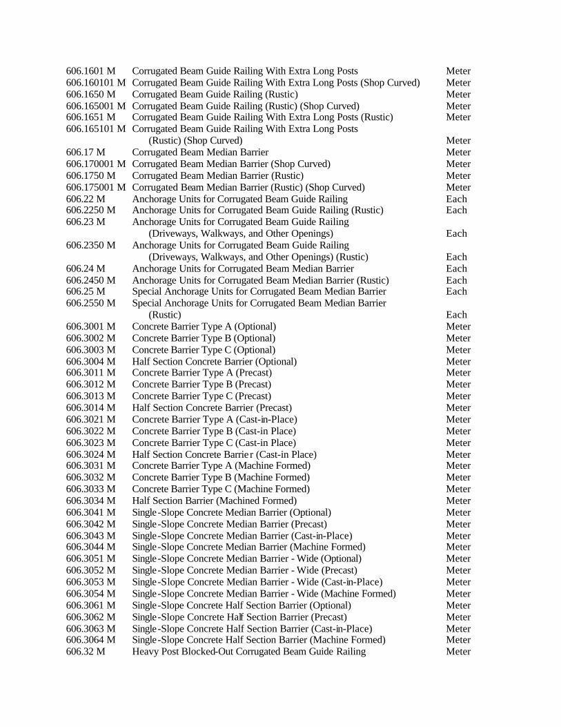
606.1601 M Corrugated Beam Guide Railing With Extra Long Posts Meter 606.160101 M Corrugated Beam Guide Railing With Extra Long Posts (Shop Curved) Meter 606.1650 M Corrugated Beam Guide Railing (Rustic) Meter 606.165001 M Corrugated Beam Guide Railing (Rustic) (Shop Curved) Meter 606.1651 M Corrugated Beam Guide Railing With Extra Long Posts (Rustic) Meter 606.165101 M Corrugated Beam Guide Railing With Extra Long Posts (Rustic) (Shop Curved) Meter 606.17 M Corrugated Beam Median Barrier Meter 606.170001 M Corrugated Beam Median Barrier (Shop Curved) Meter 606.1750 M Corrugated Beam Median Barrier (Rustic) Meter 606.175001 M Corrugated Beam Median Barrier (Rustic) (Shop Curved) Meter 606.22 M Anchorage Units for Corrugated Beam Guide Railing Each 606.2250 M Anchorage Units for Corrugated Beam Guide Railing (Rustic) Each 606.23 M Anchorage Units for Corrugated Beam Guide Railing (Driveways, Walkways, and Other Openings) Each 606.2350 M Anchorage Units for Corrugated Beam Guide Railing (Driveways, Walkways, and Other Openings) (Rustic) Each 606.24 M Anchorage Units for Corrugated Beam Median Barrier Each 606.2450 M Anchorage Units for Corrugated Beam Median Barrier (Rustic) Each 606.25 M Special Anchorage Units for Corrugated Beam Median Barrier Each 606.2550 M Special Anchorage Units for Corrugated Beam Median Barrier (Rustic) Each 606.3001 M Concrete Barrier Type A (Optional) Meter 606.3002 M Concrete Barrier Type B (Optional) Meter 606.3003 M Concrete Barrier Type C (Optional) Meter 606.3004 M Half Section Concrete Barrier (Optional) Meter 606.3011 M Concrete Barrier Type A (Precast) Meter 606.3012 M Concrete Barrier Type B (Precast) Meter 606.3013 M Concrete Barrier Type C (Precast) Meter 606.3014 M Half Section Concrete Barrier (Precast) Meter 606.3021 M Concrete Barrier Type A (Cast-in-Place) Meter 606.3022 M Concrete Barrier Type B (Cast-in Place) Meter 606.3023 M Concrete Barrier Type C (Cast-in Place) Meter 606.3024 M Half Section Concrete Barrie r (Cast-in Place) Meter 606.3031 M Concrete Barrier Type A (Machine Formed) Meter 606.3032 M Concrete Barrier Type B (Machine Formed) Meter 606.3033 M Concrete Barrier Type C (Machine Formed) Meter 606.3034 M Half Section Barrier (Machined Formed) Meter 606.3041 M Single-Slope Concrete Median Barrier (Optional) Meter 606.3042 M Single-Slope Concrete Median Barrier (Precast) Meter 606.3043 M Single-Slope Concrete Median Barrier (Cast-in-Place) Meter 606.3044 M Single-Slope Concrete Median Barrier (Machine Formed) Meter 606.3051 M Single-Slope Concrete Median Barrier - Wide (Optional) Meter 606.3052 M Single-Slope Concrete Median Barrier - Wide (Precast) Meter 606.3053 M Single-Slope Concrete Median Barrier - Wide (Cast-in-Place) Meter 606.3054 M Single-Slope Concrete Median Barrier - Wide (Machine Formed) Meter 606.3061 M Single-Slope Concrete Half Section Barrier (Optional) Meter 606.3062 M Single-Slope Concrete Half Section Barrier (Precast) Meter 606.3063 M Single-Slope Concrete Half Section Barrier (Cast-in-Place) Meter 606.3064 M Single-Slope Concrete Half Section Barrier (Machine Formed) Meter 606.32 M Heavy Post Blocked-Out Corrugated Beam Guide Railing Meter
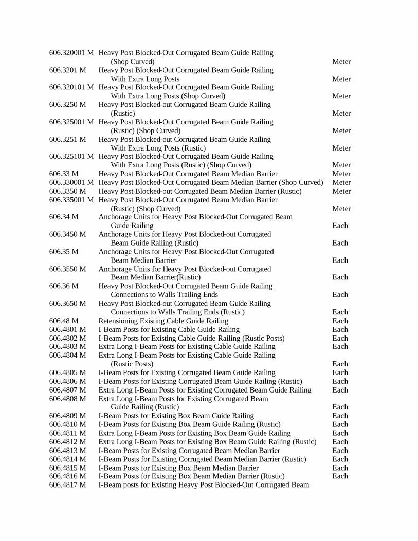
606.320001 M Heavy Post Blocked-Out Corrugated Beam Guide Railing (Shop Curved) Meter 606.3201 M Heavy Post Blocked-Out Corrugated Beam Guide Railing With Extra Long Posts Meter 606.320101 M Heavy Post Blocked-Out Corrugated Beam Guide Railing With Extra Long Posts (Shop Curved) Meter 606.3250 M Heavy Post Blocked-out Corrugated Beam Guide Railing (Rustic) Meter 606.325001 M Heavy Post Blocked-Out Corrugated Beam Guide Railing (Rustic) (Shop Curved) Meter 606.3251 M Heavy Post Blocked-out Corrugated Beam Guide Railing With Extra Long Posts (Rustic) Meter 606.325101 M Heavy Post Blocked-Out Corrugated Beam Guide Railing With Extra Long Posts (Rustic) (Shop Curved) Meter 606.33 M Heavy Post Blocked-Out Corrugated Beam Median Barrier Meter 606.330001 M Heavy Post Blocked-Out Corrugated Beam Median Barrier (Shop Curved) Meter 606.3350 M Heavy Post Blocked-out Corrugated Beam Median Barrier (Rustic) Meter 606.335001 M Heavy Post Blocked-Out Corrugated Beam Median Barrier (Rustic) (Shop Curved) Meter 606.34 M Anchorage Units for Heavy Post Blocked-Out Corrugated Beam Guide Railing Each 606.3450 M Anchorage Units for Heavy Post Blocked-out Corrugated Beam Guide Railing (Rustic) Each 606.35 M Anchorage Units for Heavy Post Blocked-Out Corrugated Beam Median Barrier Each 606.3550 M Anchorage Units for Heavy Post Blocked-out Corrugated Beam Median Barrier(Rustic) Each 606.36 M Heavy Post Blocked-Out Corrugated Beam Guide Railing Connections to Walls Trailing Ends Each 606.3650 M Heavy Post Blocked-out Corrugated Beam Guide Railing Connections to Walls Trailing Ends (Rustic) Each 606.48 M Retensioning Existing Cable Guide Railing Each 606.4801 M I-Beam Posts for Existing Cable Guide Railing Each 606.4802 M I-Beam Posts for Existing Cable Guide Railing (Rustic Posts) Each 606.4803 M Extra Long I-Beam Posts for Existing Cable Guide Railing Each 606.4804 M Extra Long I-Beam Posts for Existing Cable Guide Railing (Rustic Posts) Each 606.4805 M I-Beam Posts for Existing Corrugated Beam Guide Railing Each 606.4806 M I-Beam Posts for Existing Corrugated Beam Guide Railing (Rustic) Each 606.4807 M Extra Long I-Beam Posts for Existing Corrugated Beam Guide Railing Each 606.4808 M Extra Long I-Beam Posts for Existing Corrugated Beam Guide Railing (Rustic) Each 606.4809 M I-Beam Posts for Existing Box Beam Guide Railing Each 606.4810 M I-Beam Posts for Existing Box Beam Guide Railing (Rustic) Each 606.4811 M Extra Long I-Beam Posts for Existing Box Beam Guide Railing Each 606.4812 M Extra Long I-Beam Posts for Existing Box Beam Guide Railing (Rustic) Each 606.4813 M I-Beam Posts for Existing Corrugated Beam Median Barrier Each 606.4814 M I-Beam Posts for Existing Corrugated Beam Median Barrier (Rustic) Each 606.4815 M I-Beam Posts for Existing Box Beam Median Barrier Each 606.4816 M I-Beam Posts for Existing Box Beam Median Barrier (Rustic) Each 606.4817 M I-Beam posts for Existing Heavy Post Blocked-Out Corrugated Beam

Guide Railing Each 606.4818 M I-Beam posts for Existing Heavy Post Blocked-Out Corrugated Beam Guide Railing (Rustic) Each 606.4819 M Extra Long I-Beam posts for Existing Heavy Post Blocked-Out Corrugated Beam Guide Railing Each 606.4820 M Extra Long I-Beam posts for Existing Heavy Post Blocked-Out Corrugated Beam Guide Railing (Rustic) Each 606.4821 M I-Beam posts for Existing Heavy Post Blocked-Out Corrugated Beam Median Barrier Each 606.4822 M I-Beam posts for Existing Heavy Post Blocked-Out Corrugated Beam Median Barrier (Rustic) Each 606.4823 M Extra Long I-Beam posts for Existing Heavy Post Blocked-Out Corrugated Beam Median Barrier Each 606.4824 M Extra Long I-Beam posts for Existing Heavy Post Blocked-Out Corrugated Beam Median Barrier (Rustic) Each 606.50 M Resetting Cable Guide Railing Meter 606.5048 M Resetting Cable Guide Railing (New Posts) Meter 606.51 M Resetting Corrugated Beam Guide Railing Meter 606.5148 M Resetting Corrugated Beam Guide Railing (New Posts) Meter 606.52 M Resetting Corrugated Beam Median Barrier Meter 606.5248 M Resetting Corrugated Beam Median Barrier (New Posts) Meter 606.53 M Resetting Box Beam Guide Railing Meter 606.5348 M Resetting Box Beam Guide Railing (New Posts) Meter 606.54 M Resetting Box Beam Median Barrier Meter 606.5448 M Resetting Box Beam Median Barrier (New Posts) Meter 606.55 M Resetting Heavy Post Blocked-Out Corrugated Beam Guide Railing Meter 606.56 M Resetting Heavy Post Blocked-Out Corrugated Beam Median Barrier Meter 606.57 M Resetting Precast Concrete Barrier Meter 606.5710 M Resetting Precast Concrete Barrier- Half Section Meter 606.59 M Resetting Anchorage Units for Cable Guide Railing Each 606.5910 M Resetting Anchorage Units for Corrugated Beam Guide Railing or Median Barrier Each 606.5920 M Resetting Box Beam Guide Railing End Assembly Each 606.5930 M Resetting Box Beam Median Barrier End Assembly--Type A Each 606.5931 M Resetting Box Beam Median Barrier End Assembly--Type B Each 606.5940 M Resetting Anchorage Units for Heavy Post Blocked-Out Corrugated Beam Guide Railing Each 606.5945 M Resetting Anchorage Units for Heavy Post Blocked-Out Corrugated Beam Median Barrier Each 606.60 M Removing and Storing Cable Guide Railing Meter 606.61 M Removing and Storing Corrugated Beam Guide Railing Meter 606.62 M Removing and Storing Corrugated Beam Median Barrier Meter 606.63 M Removing and Storing Box Beam Guide Railing Meter 606.64 M Removing and Storing Box Beam Median Barrier Meter 606.65 M Removing and Storing Precast Concrete Barrier Meter 606.6510 M Removing and Storing Precast Concrete Barrier-Half Section Meter 606.69 M Removing and Storing Anchorage Units for Cable Guide Railing Each 606.6910 M Removing and Storing Anchorage Units for Corrugated Beam Guide Railing and Median Barriers Each 606.6920 M Removing and Storing Box Beam Guide Railing End Assembly Each 606.6930 M Removing and Storing Box Beam Median Barrier

End Assembly -Type A Each 606.6931 M Removing and Storing Box Beam Median Barrier End Assembly -Type B Each 606.6940 M Removing and Storing Anchorage Units for Heavy Post Blocked-Out Corrugated Beam Guide Railing Each 606.6945 M Removing and Storing Anchorage Units for Heavy Post Blocked-Out Corrugated Beam Median Barrier Each 606.70 M Removing and Disposing Cable Guide Railing Meter 606.71 M Removing and Disposing Corrugated Beam Guide Railing Meter 606.72 M Removing and Disposing Corrugated Beam Median Barrier Meter 606.73 M Removing and Disposing Box Beam Guide Railing Meter 606.74 M Removing and Disposing Box Beam Median Barrier Meter 606.75 M Removing and Disposing Concrete Barrier Meter 606.7510 M Removing and Disposing Concrete Barrier-Half Section Meter 606.76 M Removing and Disposing of Guide Posts, Guide Rail Posts, and Median Barrier Posts Each 606.79 M Removing and Disposing Anchorage Units for Cable Guide Railing Each 606.7910 M Removing and Disposing Anchorage Units for Corrugated Beam Guide Railing and Median Barrier Each 606.7920 M Removing and Disposing Box Beam Guide Railing End Assembly Each 606.7930 M Removing and Disposing Box Beam Median Barrier End Assembly-Type A Each 606.7931 M Removing and Disposing Box Beam Median Barrier End Assembly--Type B Each 606.7940 M Removing and Disposing Anchorage Units for Heavy Post Blocked-Out Corrugated Beam Guide Railing Each 606.7945 M Removing and Disposing Anchorage Units for Heavy Post Blocked-Out Corrugated Beam Median Barrier Each 606.81 M Guide Rail Transition Corrugated Beam to Box Beam (One or Two Way Operation) Each 606.8150 M Guide Rail Transition Corrugated Beam to Box Beam (One or Two-Way Operation) (Rustic) Each 606.82 M Guide Rail Transition Box Beam to Corrugated Beam (One Way Only) Each 606.8250 M Guide Rail Transition Box Beam to Corrugated Beam (One-way only) (Rustic) Each 606.83 M Guide Rail Transition Cable to Box Beam (One or Two Way Operation) Each 606.8350 M Guide Rail Transition Cable to Box Beam (One or Two-way Operation) (Rustic Posts and Box Beam) Each 606.84 M Guide Rail Transition Box Beam to Cable (One Way Only) Each 606.8450 M Guide Rail Transition Box Beam to Cable (One-Way Only) (Rustic Posts and Box Beam) Each 606.85 M Median Barrier Transition Corrugated Beam to Box Beam Each 606.8550 M Median Barrier Transition Corrugated Beam to Box Beam (Rustic) Each 606.86 M Guide Rail Transition Corrugated Beam to Thrie Beam Each 606.8701 M Corrugated Beam Guide Railing Transition Assembly Two Rail Steel Bridge Railing Each 606.8702 M Corrugated Beam Guide Railing Transition Assembly Four Rail Steel Bridge Railing Each 606.8703 M Corrugated Beam Guide Railing Transition Assembly Discontinuous Steel Bridge Railing Each 606.8704 M Corrugated Beam Guide Railing Transition Assembly Concrete Parapets, or Concrete Barrier Each

606.8705 M HPBO Corrugated Median Barrier Transition to Single Slope Concrete Median Barrier Each
606.8706 M HPBO Corrugated Median Barrier Transition to Jersey Shape Concrete Median Barrier Each
606.8707 M Transition Between Concrete Half Section Barrier and HPBO Corrugated Beam Guide Railing Each
606.8755 M HPBO Corrugated Median Barrier Transition to Single Slope Concrete Median Barrier (Rustic) Each
606.8756 M HPBO Corrugated Median Barrier Transition to Jersey Shape Concrete Median Barrier (Rustic) Each
606.8757 M Transition Between Concrete Half Section Barrier and HPBO Corrugated Beam Guide Railing (Rustic) Each
606.8801 M Box Beam Guide Rail Transition to Concrete Barrier (One or Two Way Operation) Each 606.8802 M Box Beam Guide Rail Transition to Concrete Barrier (One Way-Trailing End) Each 606.8803 M Transition Between Box Beam Guide Rail and Single Slope Half Section Concrete Barrier (One or Two Way Operation) Each 606.8804 M Transition Between Single Slope Half Section Concrete Barrier and Box Beam Guide Rail (One Way - Trailing End of Barrier) Each 606.8805 M Transition Between Box Beam Median Barrier and Single Slope Concrete Median Barrier Each 606.8853 M Transition Between Box Beam Guide Rail and Single Slope Half Section Concrete Barrier (One or Two Way Operation) (Rustic) Each 606.8854 M Transition Between Single Slope Half Section Concrete Barrier and Box Beam Guide Rail (One Way - Trailing End of Barrier) (Rustic) Each 606.8855 M Transition Between Box Beam Median Barrier and Single Slope Concrete Median Barrier (Rustic) Each 606.89 M Guide Rail Transition Box Beam to Heavy Post
Blocked-Out Corrugated Beam Each 606.8950 M Guide Rail Transition Box Beam to Heavy Post
Blocked-Out Corrugated Beam (Rustic) Each 606.9001 M Transition between Standard (NJ) Concrete Barrier
and Single-Slope Concrete Barrier Each 606.9002 M Transition between Wide and Normal Single Slope Concrete
Median Barrier Each 606.9401 M Pier Protection (One Way) Meter 606.9402 M Pier Protection (Two Way) Meter SECTION 607 - FENCES 607-1 DESCRIPTION. This work shall consist of furnishing and erecting fencing and metal fence gates of the type and size, and at the locations shown on the plans or as directed by the Engineer. Construction of fencing and gates shall be done in accordance with the specifications, the standard sheets, and the plans, and in reasonable close conformity with the lines and grades shown on the plans or established by the Engineer. 607-1.01 Fence Types. The fence shall be designated as follows: Optional Chain Link Fence Type I Optional Chain Link Fence Type II

Vinyl Coated Chain Link Fence on Plastic Coated Frame Right-of-Way Fencing The options for Type I and Type II chain link fences shall be as follows: TYPE I Fabric Options Frame Options Coated Steel Fence Fabric Mischmetal Alloy Coating (95% Zinc 5% Aluminum- Mischmetal Alloy) (95% Zinc 5% Aluminum) Galvanized Steel Galvanized Steel Aluminum Combined Coating on Steel Aluminum Coated Steel Aluminum Aluminum Coated Steel TYPE II Fabric Options Frame Options Coated Steel Fence Fabric Mischmetal Alloy Coating (95% Zinc 5% Aluminum- Mischmetal Alloy) (95% Zinc 5% Aluminum) Galvanized Steel Galvanized Steel Vinyl Coated Steel Combined Coating on Steel Aluminum Plastic on Steel Aluminum Coated Steel Aluminum Aluminum Coated Steel Fence gates for Type I and Type II optional fences shall be consistent with the fabric and frame option selected for the contract. Fence frame and fabric selected shall be consistent throughout the contract except where intermixing is permitted by the Engineer. 607-2 MATERIALS. Materials shall conform to the requirements specified in the following subsections of Section 700--Materials: Zinc Chromate Primer 708-04 Aluminum Fence Fabric 710-01 Galvanized Steel Fence Fabric 710-02 Vinyl Coated Steel Fence Fabric 710-03 Aluminum Coated Steel Fence Fabric 710-04 Coated Steel Fence Fabric (95% Zinc 5% Aluminum-Mischmetal Alloy) 710-05 Steel and Iron Posts, Rails, Braces and Fittings for Chain-Link Fence 710-10.03 Aluminum Posts, Rails, Braces and Fittings for Chain-Link Fence 710-11 Plastic Coated Posts, Rails, Braces and Fittings for Chain-Link Fence 710-12 Right-of-Way Fencing 710-30 607-2.01 Portland Cement Concrete for Bases. Portland Cement concrete used for bases shall be Class A or C conforming to the requirements of Section 501 Portland Cement Concrete--General except that requirements for automated batching shall not apply.

607-2.02 Right-of-Way Fencing. The Contractor has the option of using posts and braces fabricated from either high carbon shapes of steel or pressure treated wood meeting the requirements of §710-30 Right-of-Way Fencing. 607-2.03 Fence Gates. Fence gates for Right-of-Way Fencing shall Conform to the requirements for Right-of-Way Fence Gates of §710-30. Fence gates for Chain-Link Fence shall conform to the following: A. Gate Frames. Frames shall be constructed of tubular members welded at all corners or assembled with corner fittings. Where corner fittings are used gates shall have 10 mm nominal diameter truss rods to prevent sag or twist. Gate leaves shall have vertical intermediate bracing so that no vertical members are more than 2.4 m apart. Gate leaves over 3 m long shall have a horizontal brace or a 10 mm nominal diameter diagonal truss rod. Gate leaves over 5 m shall have both a horizontal brace and a 10 mm nominal diameter truss rod. B. Gate Fabric. Gate fabric shall conform to the requirements of the fabric used in the fence construction. C. Gate Hinges. Hinges shall be weldable steel, cast steel or malleable iron 180E offset industrial type. The hinges shall not twist or turn under the action of the gate. The gates shall be capable of being opened and closed easily by one person. Hinges shall be galvanized in accordance with §719-01 Type I. D. Gate Latches. Latches, stops and keepers shall be provided for all gates. Latches shall have a plungerbar arranged to engage the center stop, except that single left gate openings with an opening of less than 3 m may use a forked latch. Latches shall be arranged for locking and the Contractor shall provide a lock with triplicate keys for each gate. Center stops shall consist of a device arranged to be set in concrete and to engage a plunger-bar of the latch of double leaf gates. No stop is required for single leaf gates. Keepers shall consist of a mechanical device for securing the free end of the gate when in the full open position. 607-3 CONSTRUCTION DETAILS 607-3.01 General. The Contractor shall perform such clearing and grubbing as may be necessary to construct the fence to the required grade and alignment. At locations where breaks in a run of fencing are required, or at intersections with existing fences, appropriate adjustment in post spacing shall be made to conform to the requirements for the type of closure indicated. When the plans require that the posts, braces, or anchors be embedded in concrete, the Contractor shall install temporary guys or braces as may be required to hold the posts in proper position until such time as the concrete has set sufficiently to hold the posts. Unless otherwise permitted, no materials shall be installed on posts or strain placed on guys and bracing set in concrete until seven days have elapsed from the time of placing the concrete. All posts shall be set vertically and to the required grade and alignment. Cutting of the tops of the posts will be allowed only with the approval of the Engineer and under the Engineer's specified conditions. Wire or fencing of the size and type required shall be firmly attached to the posts and braces in the manner indicated. All wire shall be stretched taut and be installed to the required elevations. At each location where an electric transmission, distribution or secondary line crosses any of the types of fences covered by these specifications, the Contractor shall furnish and install a ground conforming to the requirements of Subsection 9 of the National Electric Safety Code.

Fence shall generally follow the contour of the ground, with the bottom of fence fabric no less than 25 mm nor more than 150 mm from the ground surface. Grading shall be performed where necessary to provide a neat appearance. Line posts shall be spaced equidistant in the fence line at the spacing shown on the plans, standard sheets or as directed by the Engineer. End, corner, and intermediate posts shall be placed at the locations indicated on the plans, standard sheets or as directed by the Engineer, and shall be braced as shown on the plans or standard sheets. When chain link fence is on a long curve intermediate posts shall be evenly spaced so that the strain of the fence will not bend the line posts. All end, corner, and intermediate posts shall be set plumb in concrete bases of the depth and diameter shown on the plans or standard sheets. The Contractor shall have the option of setting the line posts in concrete bases or using methods of driving and anchoring specified by the fence manufacturer and approved by the Engineer. The concrete bases shall be rough cast in the ground around the posts. The top surfaces shall be domed to shed water and provide a neat workmanlike appearance when completed. Extensions of up 45 minutes for the allowed time for pouring the concrete will be permitted. 607-3.02 Chain-Link Fencing with Top Rail. Posts shall be set so they are equidistant with a maximum of 3 m centers. All top rails shall pass through the base of the post caps and shall form a continuous brace from end to end of each stretch of fence. Top rail lengths shall be joined with sleeve couplings with expansion sleeves provided at 30 m intervals. Top rails shall be securely fastened to end posts by means of approved rail end connectors. Horizontal braces shall be provided at all intermediate posts, midway between the top rail and ground as shown on the plans or standard sheets. Diagonal truss rods shall be installed with the horizontal braces as indicated on the plans or standard sheets. Fence fabric shall be installed approximately 50 mm above the ground level and securely fastened along the bottom, and to all braces, top rails, line and pull posts, at the intervals indicated on the standard sheets by approved methods. The fabric shall be secured to all end, corner and gate posts with stretcher bars fastened to the posts, with stretcher bands spaced at a maximum of 355 mm and in a manner permitting adjustment of the fabric tension. If the Contractor elects the option of using one piece roll-formed sections, the fence fabric shall be integrally woven into the fabric loops on the end, corner, pull and gate posts. The fabric shall be attached to the top braces and line posts as shown on the standard sheets. 607-3.03 Chain-Link Fencing with Top Tension Wire. The construction details specified in §607-3.02 Chain Link Fencing with Top Rail shall apply with the following modifications: A. Top tension wire shall be installed as shown on the plans, standard sheets, or as directed by the Engineer. B. All posts shall be spaced equidistant in the fence line on a maximum of 2.4 m centers. C. Additional pull posts shall be placed at locations indicated on the plans or standard sheets. Brace assemblies shall be installed at each intermediate post as indicated on the plans or standard sheets. 607-3.04 Vinyl Coated Chain-Link Fencing on Plastic Coated Frame. The construction details specified in §607-3.02 Chain-Link Fencing with Top Rail or §607-3.03 Chain-Link Fencing with Top Tension Wire shall apply with the following addition: If any of the resin clad material specified under this item has the protective resin coating damaged so its effectiveness to prevent corrosion of the base material is impaired, the Contractor shall repair such parts by applying one coat of an approved compound of a color to match original material.

607-3.05 Aluminum Posts. Aluminum posts shall be set in accordance with requirements pertaining to fence posts of §607-3.01 General, and §607-3.02 Chain-Link Fencing with Top Rail or §607-3.03 Chain-Link Fencing with Top Tension Wire and with the following additional requirement: The portions of aluminum posts that will be in contact with the concrete bases shall be coated with Zinc Chromate Primer conforming to the requirements of §708-04. The primer shall be thoroughly dry before setting of the post in the concrete. 607-3.06 Right-of-Way. Fencing posts shall be set plumb and firm to the satisfaction of the Engineer in properly prepared post holes, as indicated on the plans or standard sheet. The concrete for post holes where required shall be placed in accordance with the requirements of §607-3.01 General. All line posts of the type and size shown on the plans or standard sheets shall be placed equidistant in the fence line. Wood line posts shall be placed on a maximum of 4.5 m centers and metal line posts shall be placed on a maximum of 3 m centers. Intermediate posts and post assemblies, end posts, corner posts, approach spans, and bracing shall be as shown on the plans or standard sheets. The woven wire fencing shall be fastened to all steel line posts with at least 5 galvanized wire fasteners or clamps and to all steel end, intermediate and corner posts with aluminum wire not less than 4 mm diameter. The woven wire fencing shall be fastened to all wood posts with either 40 mm galvanized or aluminum staples. The top and bottom wires and every other in-between wires shall be stapled, alternating the stapling of the in-between wires on successive posts. 607-3.07 Fence Gates. The Contractor shall construct metal fence gates of the type and size as indicated on the plans or standard sheets, and in the location shown or ordered by the Engineer. 607-4 METHOD OF MEASUREMENT 607-4.01 General. The quantity to be paid for all fencing exclusive of fence gates and fencing of the types listed in subsequent subsections, will be the number of linear meters of chain-link fencing measured along the top of fencing, center to center of end posts, properly furnished and installed in accordance with the plans, specifications, standard sheets and directions of the Engineer. An allowance of 3 m will be added for each end post, corner post and pull post installed in accordance with the plans, specifications, standard sheets and directions of the Engineer. 607-4.02 Right-of-Way Fencing. Right-of-Way Fencing shall be measured as the number of meters along the top of the fencing from center to center of the end posts, properly furnished and installed in accordance with the plans, specifications, standard sheets and directions of the Engineer. An allowance of 6 m will be added for each end post, corner post, intermediate post, and approach post installed in accordance with the plans, specifications, standard sheets and directions of the Engineer. 607-4.03 Fence Gates. Fence gates shall be measured as the number of complete gates furnished and erected in accordance with the specifications, plans, standard sheets and directions of the Engineer. 607-5 BASIS OF PAYMENT 607-5.01 General. The unit price bid per linear meter of fencing shall include the cost of furnishing all labor, materials, tools and equipment necessary to satisfactorily complete the work. 607-5.02 Fence Gates. The unit price bid for each size gate shall cover the cost of furnishing all labor, materials, tools and equipment necessary to satisfactorily complete the work and shall include all
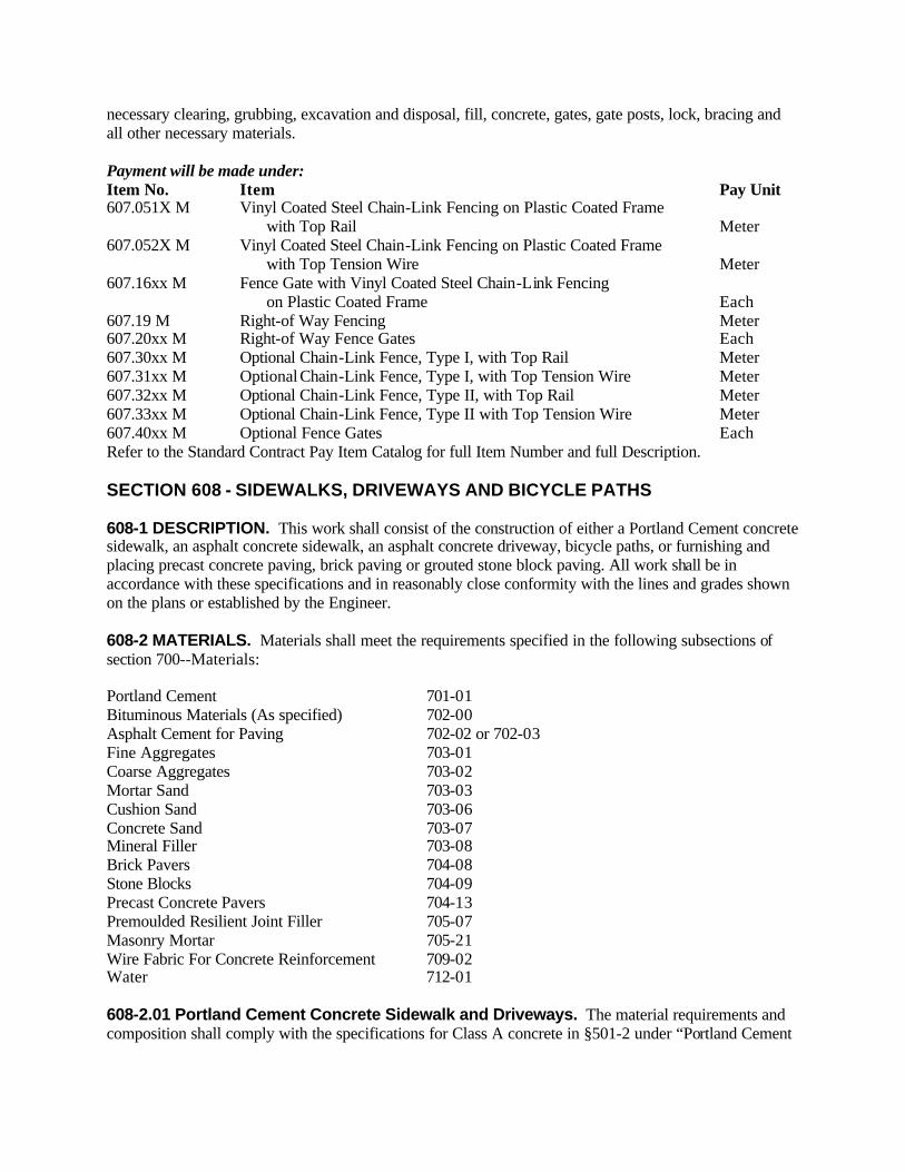
necessary clearing, grubbing, excavation and disposal, fill, concrete, gates, gate posts, lock, bracing and all other necessary materials. Payment will be made under: Item No. Item Pay Unit 607.051X M Vinyl Coated Steel Chain-Link Fencing on Plastic Coated Frame with Top Rail Meter 607.052X M Vinyl Coated Steel Chain-Link Fencing on Plastic Coated Frame with Top Tension Wire Meter 607.16xx M Fence Gate with Vinyl Coated Steel Chain-Link Fencing on Plastic Coated Frame Each 607.19 M Right-of Way Fencing Meter 607.20xx M Right-of Way Fence Gates Each 607.30xx M Optional Chain-Link Fence, Type I, with Top Rail Meter 607.31xx M Optional Chain-Link Fence, Type I, with Top Tension Wire Meter 607.32xx M Optional Chain-Link Fence, Type II, with Top Rail Meter 607.33xx M Optional Chain-Link Fence, Type II with Top Tension Wire Meter 607.40xx M Optional Fence Gates Each Refer to the Standard Contract Pay Item Catalog for full Item Number and full Description. SECTION 608 - SIDEWALKS, DRIVEWAYS AND BICYCLE PATHS 608-1 DESCRIPTION. This work shall consist of the construction of either a Portland Cement concrete sidewalk, an asphalt concrete sidewalk, an asphalt concrete driveway, bicycle paths, or furnishing and placing precast concrete paving, brick paving or grouted stone block paving. All work shall be in accordance with these specifications and in reasonably close conformity with the lines and grades shown on the plans or established by the Engineer. 608-2 MATERIALS. Materials shall meet the requirements specified in the following subsections of section 700--Materials: Portland Cement 701-01 Bituminous Materials (As specified) 702-00 Asphalt Cement for Paving 702-02 or 702-03 Fine Aggregates 703-01 Coarse Aggregates 703-02 Mortar Sand 703-03 Cushion Sand 703-06 Concrete Sand 703-07 Mineral Filler 703-08 Brick Pavers 704-08 Stone Blocks 704-09 Precast Concrete Pavers 704-13 Premoulded Resilient Joint Filler 705-07 Masonry Mortar 705-21 Wire Fabric For Concrete Reinforcement 709-02 Water 712-01 608-2.01 Portland Cement Concrete Sidewalk and Driveways. The material requirements and composition shall comply with the specifications for Class A concrete in §501-2 under “Portland Cement

Concrete--General.” Concrete shall be proportioned in accordance with the aggregate weights specified for Class A concrete in Table 501-3, Concrete Proportions. 608-2.02 Asphalt Concrete Sidewalks, Driveways, and Bicycle Paths. The mixture requirements for these items shall either be 9.5 mm or 19.0 mm mixtures. These mixtures shall be designed for <0.3 million ESALs and produced in accordance to Section 401 using coarse aggregate Type F9. The number of courses and course thicknesses shall be as given in Table 608 - 1, Hot Mix Asphalt Composition. TABLE 608-1 HOT MIX ASPHALT COMPOSITION Total Paved Thickness 9.5 mm Mix 19.0 mm Mix Number of Courses 40 mm 40 mm 1 50 mm 50 mm 1 80+ mm 40 mm 40+ mm 2+
Notes: 1. For the 19.0 mm mixture, the maximum thickness that can be placed in one pass is 75 mm. 2. A course shall consist of one or more separate lifts of hot mix asphalt, as directed by the Engineer, to attain the indicated thickness. 608-2.03 Brick Paved Sidewalks and Driveways. Brick pavers shall meet the requirements of §704-08 and shall be the size(s), shape(s) and color(s) as specified in the contract documents. A. Neoprene-Modified Asphalt Adhesive. Neoprene-modified asphalt adhesive shall consist of 2% neoprene, grade WM1, oxidized asphalt with a R & B softening point of 68EC minimum and a penetration of 80, and 10% asbestos-free fibers. B. Mortar for Brick Paving. Mortar for brick paving shall meet the requirements outlined in §705-21 Masonry Mortar. C. Sand-Cement Setting Bed. Sand-Cement Setting Bed shall consist of 1 part Portland Cement Type 2, §701-01 and 6 parts of Fine Aggregate, §703-01 by volume. 608-2.04 Grouted Stone Block Paved Sidewalks and Driveways. Stone blocks shall meet the requirements of Section §704-09 and shall be the size(s), shape(s) and color(s) as specified in the contract documents. A. Sand-Cement Setting Bed. Sand-cement setting bed shall consist of 1 part Portland Cement Type 2, §701-01. and 6 parts of Fine Aggregate, §703-01 by volume. B. Mortar For Stone Block Paving. Mortar for stone block paving shall meet the requirements outlined in §705-21 Masonry Mortar. 608-2.05 Precast Concrete Block Paved Sidewalks and Driveways. Precast concrete pavers shall meet the requirements of §704-13 and shall be the size(s), shape(s) and color(s) as specified in the contract documents. Unless otherwise specified in the contract documents the setting bed material shall consist of hard, durable; uncoated particles of soil or rock, free from lumps of clay and all deleterious substances. Setting Bed Material shall meet the following gradation requirements:

Sieve Size Percent Passing by Weight 6.3 mm 100 2.0 mm 50-85 425 :m 20-45 75 :m 3-10 608-3 CONSTRUCTION DETAILS 608-3.01 Concrete Sidewalk and Driveways. The general construction details for manufacturing and transporting concrete shall meet the requirements of Section 501, Portland Cement Concrete- General. Placing and curing of concrete shall meet the requirements of Section 502, Portland Cement Concrete Pavement except that when a membrane curing compound is used it shall be clear with fugitive dye unless otherwise permitted by the Engineer. The concrete shall be placed in one course to the full depth shown in the contract documents. Wire fabric for concrete reinforcement, §709-02, shall be embedded at mid-depth in the slab. The wire fabric shall consist of MW19 or MW20 wire at 150 mm centers transversely and longitudinally. Transverse construction joints shall extend to the full depth of the slab and shall be spaced 6 m to 8 m apart. The edges of such joints shall be finished with an edging tool having a 6 mm radius. The concrete shall be finished to produce a smooth surface and then lightly broomed to a uniform texture. The edges of all sidewalk slabs shall be tooled. Unless otherwise specified in the contract documents the concrete surface shall be scored and tooled at intervals of 1.5 m. A premoulded resilient joint filler, §705-07, shall be installed at all joints between sidewalk and curb, pavement, building, etc. 608-3.02 Asphalt Concrete Sidewalks, Driveways, and Bicycle Paths. The provisions under §402-3 Construction Details for Hot Mix Asphalt (HMA) Pavements, shall apply. The sidewalks, driveways, and bicycle paths shall be constructed to the depths and dimensions indicated in the contract documents. TABLE 608-1 ASPHALT CONCRETE COMPOSITION Total Paved Thickness
Type 7 Type 6 Type 3 Type 1 Number of Courses
25 mm 25 mm or 25 mm 1 30 mm 30 mm or 30 mm 1 40 mm 40 mm or 40 mm 1 50 mm 50 mm 1 65 mm 25 mm or 25 mm on 40 mm 2 75 mm 25 mm or 25 mm on 50 mm 2 90 mm 25 mm or 25 mm on 65 mm 2 100 mm 40 mm or 40 mm on 60 mm 2 115 mm 40 mm or 40 mm on 75 mm 2 125 mm 40 mm or 40 mm on 90 mm 2 140 mm 40 mm or 40 mm on 100 mm 2 140+ mm 25 mm or 25 mm on 40 mm on Nec. 3
Notes: 1. Type 6 or Type 7 Top Courses shall not be applied directly to Type I Base Course.
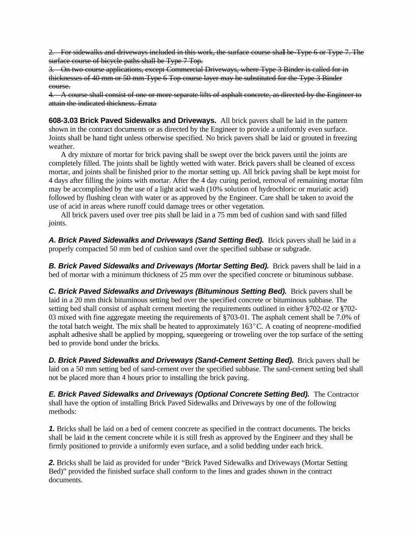
2. For sidewalks and driveways included in this work, the surface course shall be-Type 6 or Type 7. The surface course of bicycle paths shall be Type 7 Top. 3. On two course applications, except Commercial Driveways, where Type 3 Binder is called for in thicknesses of 40 mm or 50 mm Type 6 Top course layer may be substituted for the Type 3 Binder course. 4. A course shall consist of one or more separate lifts of asphalt concrete, as directed by the Engineer to attain the indicated thickness. Errata 608-3.03 Brick Paved Sidewalks and Driveways. All brick pavers shall be laid in the pattern shown in the contract documents or as directed by the Engineer to provide a uniformly even surface. Joints shall be hand tight unless otherwise specified. No brick pavers shall be laid or grouted in freezing weather. A dry mixture of mortar for brick paving shall be swept over the brick pavers until the joints are completely filled. The joints shall be lightly wetted with water. Brick pavers shall be cleaned of excess mortar, and joints shall be finished prior to the mortar setting up. All brick paving shall be kept moist for 4 days after filling the joints with mortar. After the 4 day curing period, removal of remaining mortar film may be accomplished by the use of a light acid wash (10% solution of hydrochloric or muriatic acid) followed by flushing clean with water or as approved by the Engineer. Care shall be taken to avoid the use of acid in areas where runoff could damage trees or other vegetation. All brick pavers used over tree pits shall be laid in a 75 mm bed of cushion sand with sand filled joints. A. Brick Paved Sidewalks and Driveways (Sand Setting Bed). Brick pavers shall be laid in a properly compacted 50 mm bed of cushion sand over the specified subbase or subgrade. B. Brick Paved Sidewalks and Driveways (Mortar Setting Bed). Brick pavers shall be laid in a bed of mortar with a minimum thickness of 25 mm over the specified concrete or bituminous subbase. C. Brick Paved Sidewalks and Driveways (Bituminous Setting Bed). Brick pavers shall be laid in a 20 mm thick bituminous setting bed over the specified concrete or bituminous subbase. The setting bed shall consist of asphalt cement meeting the requirements outlined in either §702-02 or §702-03 mixed with fine aggregate meeting the requirements of §703-01. The asphalt cement shall be 7.0% of the total batch weight. The mix shall be heated to approximately 163EC. A coating of neoprene-modified asphalt adhesive shall be applied by mopping, squeegeeing or troweling over the top surface of the setting bed to provide bond under the bricks. D. Brick Paved Sidewalks and Driveways (Sand-Cement Setting Bed). Brick pavers shall be laid on a 50 mm setting bed of sand-cement over the specified subbase. The sand-cement setting bed shall not be placed more than 4 hours prior to installing the brick paving. E. Brick Paved Sidewalks and Driveways (Optional Concrete Setting Bed). The Contractor shall have the option of installing Brick Paved Sidewalks and Driveways by one of the following methods: 1. Bricks shall be laid on a bed of cement concrete as specified in the contract documents. The bricks shall be laid in the cement concrete while it is still fresh as approved by the Engineer and they shall be firmly positioned to provide a uniformly even surface, and a solid bedding under each brick. 2. Bricks shall be laid as provided for under “Brick Paved Sidewalks and Driveways (Mortar Setting Bed)” provided the finished surface shall conform to the lines and grades shown in the contract documents.

608-3.04 Grouted Stone Block Paved Sidewalks and Driveways. All grouted stone block pavers shall be laid in the pattern shown in the contract documents or as directed by the Engineer to provide a uniformly even surface. Joints between blocks shall be a maximum of 32 mm or as specified. No blocks shall be laid or grouted in freezing weather. Unless otherwise approved by the Engineer, a dry mixture of mortar as specified for Brick Paved Sidewalks and Driveways, §608-2.03, shall be swept over the stone blocks until the joints are completely filled and the joints lightly wetted with water prior to the mortar setting up. All grouted stone block paving shall be kept moist for four days after filling the joints with mortar. After the four day curing period, removal of remaining mortar film may be accomplished by the use of a light acid wash (10% + solution of hydrochloric acid) followed by flushing clean with water, or as approved by the Engineer. Care shall be taken to avoid the use of acid in areas where runoff could damage trees or other vegetation. All blocks used over tree pits shall be laid in a 25 mm bed of cushion sand with sand filled joints. A. Grouted Stone Block Paved Sidewalks and Driveways (Sand Setting Bed). Blocks shall be laid in a 75 mm bed of cushion sand over the specified subbase or subgrade. B. Grouted Stone Block Paved Sidewalks and Driveways (Mortar Setting Bed). Blocks shall be laid in a bed of mortar with a minimum thickness of 25 mm over the specified concrete or bituminous subbase. C. Grouted Stone Block Paved Sidewalks and Driveways (Sand-Cement Setting Bed). Blocks shall be laid on a 50 mm setting bed of sand-cement over the specified subbase. The sand-cement setting bed shall not be placed more than 4 hours prior to installing the block paving. D. Grouted Stone Block Paved Sidewalks and Driveways (Optional Concrete Setting Bed). The Contractor shall have the option of installing Grouted Stone Block Paved Sidewalks and Driveways by one of the following methods: 1. Blocks shall be laid on a bed of cement concrete as specified in the contract documents. The blocks shall be laid in the cement concrete while it is still fresh as approved by the Engineer and they shall be firmly positioned to provide a uniformly even surface, and a solid bedding under each stone block. 2. Blocks shall be laid as provided for under “Grouted Stone Block Paved Sidewalks and Driveways (Mortar Setting Bed)” provided the finished surface shall conform to the lines and grades shown in the contract documents. 608-3.05 Precast Concrete Block Paved Sidewalks and Driveways. Precast concrete pavers shall be laid in the pattern shown in the contract documents or as directed by the Engineer to provide a uniformly even surface. Joints shall be hand tight unless otherwise specified. No pavers shall be laid in freezing weather. After the pavers are in place, an approved sand joint filler shall be swept over the pavers until the joints are completely filled. Unless otherwise specified in the contract documents, or directed by the Engineer, the Contractor shall install the pavers in accordance with the manufacturer's recommended procedures. Precast Concrete Block Paved Sidewalks and Driveways (Granular Material Setting Bed). Unless otherwise specified in the contract documents, precast concrete pavers shall be laid on a setting bed not to exceed 50 mm of uniformly compacted material placed over the specified subbase. 608-4 METHOD OF MEASUREMENT
608-4.01 Concrete Sidewalks and Driveways. Portland Cement concrete sidewalks and driveways will be measured by the number of cubic meters of cement concrete necessary to construct sidewalks and driveways shown in the contract documents or as ordered by the Engineer. 608-4.02 Asphalt Concrete Sidewalks, Driveways and Bicycle Paths. Asphalt concrete sidewalks, driveways and bicycle paths will be measured by the number of metric tons of asphalt concrete furnished and incorporated in the work. Quality payment adjustments will be measured as outlined in §402-4, Method of Measurement. 608-4.03 Brick Paved Sidewalks and Driveways. Brick paving shall be measured as the number of square meters placed as shown in the contract documents or as ordered by the Engineer. 608-4.04 Grouted Stone Block Paved Sidewalks and Driveways. Grouted stone block paving shall be measured as the number of square meters placed as shown in the contract documents or as ordered by the Engineer. 608-4.05 Precast Concrete Block Paved Sidewalks and Driveways. Precast concrete paving will be measured by the number of square meters placed as shown in the contract documents, or as ordered by the Engineer. 608-5 BASIS OF PAYMENT 608-5.01 Concrete Sidewalks and Driveways. The unit price bid per cubic meter shall include the cost of preparing the subgrade, all materials, equipment and labor necessary to complete the work as specified except that any necessary excavation and subbase course will be paid for under their appropriate items. Payment at the unit bid price will be made after the concrete sidewalk or driveway, and curing application have been properly placed. 608-5.02 Asphalt Concrete Sidewalks, Driveways, and Bicycle Paths. The unit price bid per metric ton shall include the cost of preparing the subgrade, all materials, equipment and labor necessary to complete the work as specified except that any necessary excavation and subbase course will be paid for under their appropriate items. Payment of Quality Units will be made based on the Index Price listed in the contract documents. The index price shown in the itemized proposal for each Quality Unit shall be considered the price bid. The unit (index) price is NOT to be altered in any manner by the bidder. Should the bidder alter the amount shown, the altered figure will be disregarded and the original price will be used to determine the total amount bid for the Contract. 608-5.03 Brick Paved Sidewalks and Driveways. The price bid per square meter shall include the cost of furnishing all labor, materials and equipment necessary to complete the work, including setting bed material, as specified except that any necessary excavation and subbase course will be paid for under their appropriate items; 608-5.04 Grouted Stone Block Paved Sidewalks and Driveways. The unit bid per square meter shall include the cost of furnishing all labor, materials and equipment necessary to complete the work, including setting bed material, as specified except that any necessary excavation and subbase course will be paid for under their appropriate items. 608-5.05 Precast Concrete Block Paved Sidewalks and Driveways. The unit price bid per square meter shall include the cost of all labor, materials and equipment necessary to complete the work,
including setting bed material, except that any necessary excavation and subbase course will be paid for under their appropriate items. Payment will be made under: Item No. Item Pay Unit 608.0101 M Concrete Sidewalks and Driveways Cubic Meter 608.020101 M Asphalt Concrete Sidewalks, Driveways and Bicycle Paths Metric Ton 608.020110 M Plant Production Quality Adjustment to 608.020101 M Quality Unit 608.03 M Brick Paved Sidewalks and Driveways (Sand Setting Bed) Square Meter 608.04 M Brick Paved Sidewalks and Driveways (Mortar Setting Bed) Square Meter 608.05 M Brick Paved Sidewalks and Driveways (Bituminous Setting Bed) Square Meter 608.06 M Brick Paved Sidewalks and Driveways (Sand-Cement Setting Bed) Square Meter 608.07 M Brick Paved Sidewalks and Driveways (Optional Concrete Setting Bed) Square Meter 608.08 M Grouted Stone Block Paved Sidewalks and Driveways (Sand Setting Bed) Square Meter 608.09 M Grouted Stone Block Paved Sidewalks and Driveways (Mortar Setting Bed) Square Meter 608.10 M Grouted Stone Block Paved Sidewalks and Driveways (Sand-Cement Setting Bed) Square Meter 608.11 M Grouted Stone Block Paved Sidewalks and Driveways (Optional Concrete Setting Bed) Square Meter 608.12 M Precast Concrete Block Paved Sidewalks and Driveways (Granular Material Setting Bed) Square Meter SECTION 609 - CURB AND CURB & GUTTER 609-1 DESCRIPTION. Construct and place curb, and curb & gutter, and/or reset curb as specified in the Contract Documents or established by the Engineer. 609-2 MATERIALS. The materials shall meet the requirements of the following subsections of Section 700 -Materials Details. Portland Cement, Type II 701-01 Concrete Repair Material 701-04 Concrete Grouting Material 701-05 Anchoring Material - Chemically Curing 701-07 Coarse Aggregate 703-02 Concrete Sand 703-07 Premoulded Resilient Joint Filler 705-07 Masonry Mortar 705-21 Stone Curb Anchor Bars 709-07 Quilted Covers (for Curing) 711-02 Plastic Coated Fiber Blankets (for Curing) 711-03 Polyethylene Curing Covers (White Opaque) 711-04 Membrane Curing Compound 711-05 Stone Curb 714-01 Precast Concrete Curb 714-04 Asphalt Concrete or Hot Mix Asphalt Curb 714-06
White and Yellow Pavement Marking Paints shall meet the requirements of Section 640 - Reflectorized Pavement Marking Paints. 609-2.01 (Vacant) 609-2.02 Concrete for Cast-in-Place Concrete Curb and Curb & Gutter. A. Conventionally Formed Curb and Curb & Gutter. The material requirements, mix preparation and manufacturing of the concrete shall conform to the requirements for Class A Concrete as specified in Section 501, Portland Cement Concrete - General. B. Machine Formed Concrete Curb and Curb & Gutter. Use Class J Concrete as specified in Section 501, Portland Cement Concrete - General. 609-2.03 Stone Curb and Granite Curb. Stone curb shall conform to §714-01 and shall be either sandstone or bluestone. Granite curb shall conform to the requirements for granite under Stone Curb §714-01. 609-2.04 Curb Anchors. Curb anchors for cast-in-place concrete curb, and curb & gutter shall be fabricated from material conforming to the requirements for Longitudinal Joint Ties §705-14 and to the details shown on the standard sheet for concrete curb or as indicated in the contract documents. 609-2.05 Concrete for Backing and Bedding Precast Concrete Curb, Stone Curb, and Granite Curb. The Contractor shall use any Class Concrete or a concrete mix proportioned as follows: KILOGRAMS OF AGGREGATE PER BAG OF CEMENT
Specific Gravity of Aggregate 2.60 2.70 2.80 2.90 Concrete Sand 148 153 159 165 Coarse Aggregate, CA 2 Gradation 243 252 253 271
609-3 CONSTRUCTION DETAILS 609-3.01 General. Curb, or curb & gutter found to be dirty, damaged or out of alignment shall be cleaned, repaired, or replaced as necessary by the Contractor to the satisfaction of the Engineer prior to final acceptance of the work. When the Contract Documents have no reference to placing curb across driveway entrances, no curb shall be placed across driveway entrances. 609-3.02 Precast Concrete Curb, Stone Curb, and Granite Curb. All precast concrete curb, stone curb, and granite curb shall be set on a 75 mm thick continuous bed of dry concrete mix, or on a 75 mm thick dry concrete mix bed at the joints as shown on the Standard Sheets and plastic concrete between the joints, or on a 75 mm minimum thick continuous bed of compacted granular material, at the Contractor's option. Precast concrete curb, stone curb, and granite curb shall be backed up with concrete using one of the following methods depending on the type of pavement: A. Portland Cement Concrete (Rigid) Pavement. The Contractor shall place concrete backing behind the curb at each joint. The backing shall extend a minimum of 300 mm on both sides of the joint. The minimum height of the concrete backing shall be one half of the concrete pavement thickness and shall be measured from the bottom of the curb.

B. Hot Mix Asphalt (Flexible) Pavement. The Contractor shall place a continuous concrete backing behind the curb. The minimum height of the concrete backing shall be 255 mm or to the top of the hot mix asphalt pavement, whichever is greater, measured from the bottom of the curb. Precast curb and stone curb with and without sawed ends, not on structure, shall be butted together with no mortar between the joints. When the curb is set next to a concrete (rigid) pavement, grout conforming to §701-04 Concrete Repair Material or §705-21 Masonry Mortar shall be placed in the joint formed between the curb and the pavement. The grout shall extend from the bottom to the top of the pavement slab. Before proceeding with any further work adjacent to the curb, the curb shall be backfilled with material approved by the Engineer and the backfill material shall be thoroughly tamped. 609-3.03 Stone Curb and Granite Curb - Bridge Type. The requirements of §609-3.02 shall apply with the following modifications: A. Unless special construction details are called for in the contract documents, Type A and Type T2 curbs, when not on structures, shall be set true to line and grade on a concrete bedding. B. Types F1, G1, M, R1, R2, S and T1 curbs shall be set in full mortar beds on structures. Excess mortar which extrudes around the curb shall be struck off flush with the front face of the curb and the top surface of the roadway. C. Anchor bars for stone and granite bridge curb shall be installed where and as indicated in the contract documents. All curb on structures shall be fitted together allowing 6 mm full mortared joints finished flush with exposed curb surfaces. Curb surfaces shall be cleaned of excess mortar to the satisfaction of the Engineer. Mortar used for bedding and filling of joints shall conform to §705-21 Masonry Mortar or §701-04 Concrete Repair Material. 609-3.04 Cast-In-Place Concrete Curb and Curb & Gutter. Cast-in-place concrete curb and curb & gutter shall either be conventionally formed or machine formed to the size and shape shown on the standard sheets or as indicated in the contract documents. Curb anchors, as required on the standard sheets or the contract documents, shall not be coated with materials which impair bonding. Curb anchors shall be installed a minimum of 300 mm from the ends of a pavement slab. Curb anchors for new concrete pavement, when placed simultaneously with pavement concrete, shall be placed by equipment which can demonstrate to the satisfaction of the Engineer placement of the anchors in accordance with these specifications. Curb anchors, when not placed simultaneously with pavement concrete, shall be placed rigidly secured by chairs or other supports to prevent displacement of the anchors when pavement concrete is placed. Curb anchors for existing concrete pavement shall be inserted into holes drilled in the side of the existing concrete pavement. The holes shall be thoroughly cleaned and filled with Concrete Grouting Material §701-05 or Anchoring Materials - Chemically Curing §701-07 immediately before placing the curb anchor. The curb anchor shall be securely supported in position until the grout has hardened. Curing of the curb and curb & gutter shall comply with the requirements of §502-3.11 Curing, except that a clear membrane curing compound with fugitive dye conforming to the requirements of Membrane Curing Compound §711-05 may be used in lieu of the white pigmented membrane. A. Conventionally Formed Curb and Curb & Gutter
1. Forms. Forms shall be free from warp and of such construction that there will be no interference to inspection for grade and alignment. All forms shall extend to the full curb depth and be secured so no displacement will occur during the placement of concrete. 2. Casting Segments. Curb and curb & gutter shall be cast in segments having a uniform length of approximately 3 m. The joints between segments shall not exceed 6 mm in width. When curb and curb & gutter is constructed next to concrete pavement, the curb and curb & gutter joints shall line up with the pavement joints or additional joints shall be provided in the curb and curb & gutter which line up with the pavement joints. 3. Expansion Joints. Expansion joints shall be 18 mm wide and contain Premoulded Resilient Joint Filler §705-07. The filler shall be cut to conform to the cross section of the curb and curb & gutter. Expansion joints shall be located at all immovable objects (bridge structures, etc.), adjacent to expansion joints in the pavement, and where shown in the contract documents or directed by the Engineer. Expansion joints will not be required at regular intervals unless otherwise shown in the contract documents. 4. Concrete Placing and Vibrating. Concrete shall be placed in the forms in accordance with the applicable requirements of §555-3.04 and shall be compacted with an immersion type mechanical vibrator. The vibrator shall be of a size and weight capable of thoroughly vibrating the concrete without damaging or misaligning the forms. The forms shall be le ft in place until the concrete has hardened sufficiently to permit removal without damage to the curb and curb & gutter. The front form may be removed before the other forms to facilitate finishing the curb and removal of the joint dividers. After removal of the forms, the exposed faces of the curb and curb & gutter shall be immediately rubbed to a uniform surface. No plastering will be permitted. B. Machine Formed Concrete Curb and Curb & Gutter. The equipment proposed for use by the Contractor shall demonstrate, to the satisfaction of the Engineer, the capability of placing the concrete in accordance with these specifications. When machine forming, the Contractor may provide additional width of curb without any other change in shape or dimension, if provided by the Contractor at no additional cost to the State. If the Contract Documents or the Engineer require no curb be placed across driveway entrances or the Contract Documents have no reference to placing curb across driveway entrances, the Contractor may continue placing curb across driveway entrances but the curb placed across driveway entrances, excluding transitions, must be cut out and the concrete disposed in a manner approved by the Engineer. Any curb and curb & gutter placed outside the tolerance of 12 mm of the established line or 6 mm of the established grade shall be removed and replaced by the Contractor. 1. Crack Control Joints. Crack control joints shall be formed or saw cut to a width of 3 mm minimum, 6 mm maximum and to a depth of 38 mm. The cut or formed joints shall extend slightly below the surface of the adjacent pavement and shall be spaced at 3 m intervals. When the curb, and curb & gutter is constructed next to concrete pavement, the curb and curb & gutter joints shall line up with the pavement joints or additional joints shall be provided in the curb and curb & gutter which line up with the pavement joints. The saw cut or formed joints shall be left unfilled. 2. Expansion Joints. Expansion joints shall be 18 mm wide and contain Premoulded Resilient Joint Filler §705-07. The filler shall be cut to conform to the cross section of the curb and curb & gutter. The expansion joints shall be located at all immovable objects (bridge structures, etc.), adjacent to expansion joints in the pavement, where shown in the contract documents, or directed by the Engineer. Expansion joints shall not be required at regular intervals unless otherwise shown in the contract documents.

609-3.05 (Vacant) 609-3.06 Optional Curb. Under optional curb, the Contractor shall have the option of placing precast concrete curb, or cast-in-place concrete curb, or granite curb. Precast concrete curb or granite curb shall be placed in accordance with the requirements of §609-3.02. Cast-in-place curb shall be placed in accordance with the requirements of §609-3.04. No intermixing of curb will be allowed without the Engineer's written permission. 609-3.07 Hot Mix Asphalt Curb. Hot mix asphalt curb shall conform to the construction requirements of §402-3, except as follows: A. Preparation of Mixture. The hot mix asphalt for curb shall be mixed in a batch type bituminous concrete mixing plant. The additive as specified in §714-06 shall be introduced into the pugmill within an accuracy of " 0.1% of the total batch weight. The additive may be introduced through a mineral filler feed system only if the above delivery tolerance can be maintained. The dry mixing time shall be a minimum of 15 seconds after the complete introduction of aggregates and additive into the pugmill. The wet mix time shall be a minimum of 45 seconds. B. Preparation of Surface. When hot mix asphalt curb is constructed on a freshly laid hot mix asphalt surface, the curb shall be laid only on a clean dry surface. When curb is to be laid on a cured or aged concrete base, hot mix asphalt pavement, or performance grade binder treated base, the surface shall be thoroughly swept and cleaned by compressed air. The surface shall be thoroughly dried and, immediately prior to placing of the hot mix asphalt mixture, shall receive a tack coat of asphalt emulsion, Material Designation 702-3001 as specified in Table 702-5. The tack coat shall be applied at a rate of 0.15 to 0.50 L/m2. The tack coat shall be prevented from spreading to areas outside of the area to be occupied by the curb. C. Placing. Hot mix asphalt curb shall be constructed by machine to the size and shape shown on the standard sheets. The machine shall be capable of placing the hot mix asphalt in accordance with these specifications to the satisfaction of the Engineer. Prior to placement, the Contractor shall demonstrate to the satisfaction of the Engineer the machine meets the following requirements: 1. The machine shall be self propelled and capable of forming curb which is uniform in texture, shape, and density. 2. The weight and the material extrusion rate of the machine shall be such that the required compaction is obtained without the machine riding above the bed on which curbing is constructed. When short sections of hot mix asphalt curb or sections with short radii are required, the Engineer may permit construction by other means, as long as the resulting curb conforms to the curb produced by machine. D. Painted Hot Mix Asphalt Curb. When painted hot mix asphalt curb is specified, it shall be painted yellow or white in accordance with the Manual of Uniform Traffic Control Devices. The paint shall be placed in accordance with the following: 1. After a curing period of not less than 72 hours, exposed surfaces of the curbing shall be sprayed or hand brushed with two coats of pavement marking paint, yellow or white as required. Each coat of paint shall be applied at the rate of 1 L per 16 m of curb.
2. The curb shall be clean and free of all foreign matter before painting. Paint shall be applied only when the air temperature is above 10°C and rising. Paint shall not be applied when there is reasonable expectation of rain. In the event the first or final coat of paint is rain damaged, as determined by the Engineer, the Contractor shall clean and repaint the curb at no additional cost to the State. 609-3.08 Resetting Curb. Care shall be taken in removing the curb to be reset so that there will be no unnecessary breakage. All curb damaged in removing, hauling, storing, or resetting shall be replaced by the Contractor. The curb shall be reset, in accordance with the requirements of §609-3.02 or §609-3.03 for resetting bridge type curbs, to the lines and grades specified in the contract documents. 609-4 METHOD OF MEASUREMENT. All curb and curb & gutter placed and curb reset under these specifications will be measured by the number of linear meters, rounded to the nearest tenth of a meter. The measurement will be taken along the top front arris line of full height, transition and terminal sections. The measurement will be taken along the top front arris line of curb reveals across driveway entrances only when placed and not removed. 609-5 BASIS OF PAYMENT 609-5.01 Concrete Curb, Curb & Gutter, Stone Curb, Granite Curb, Optional Curb. The unit price bid per meter shall include the cost of all labor, materials, curb anchors, equipment, and excavation to, in accordance with these specifications, place, backfill, grout and caulk the curb, curb & gutter. When select backfill is specified, the select backfill shall be paid under its respective items. No additional payment will be made to the Contractor when more than the minimum width of curb is placed. No additional payment will be made to the Contractor when curb is placed across driveway entrance, to facilitate concrete machine forming operations, and removed. 609-5.02 Stone Curb and Granite Curb - Bridge Type. The unit price bid per meter shall include the cost of furnishing all labor, equipment, and materials including concrete bedding, mortar for stone and granite curbs, chemically curing anchoring materials, and stone and granite curb anchors required to bed and place stone and granite bridge curb, in accordance with these specifications. 609-5.03 Hot Mix Asphalt Curb. The unit price bid per meter shall include the cost of furnishing all labor, materials, and equipment to prepare the surface for curb placement, and place the curb. If painted hot mix asphalt curb is specified, the Contractor shall also include the cost of preparing the curb for painting, furnishing the paint, and applying the paint. Progress payments will be made after the curb has been constructed to the shape and size shown on the standard sheet and/or plans. Payment will be made, at the unit price bid, for 90% of the quantity properly constructed exclusive of painting. The balance of the quantity will be paid for upon completion of the work. 609-5.04 (Vacant). 609-5.05 Resetting Curb. The unit price bid per meter shall include the cost of furnishing all labor, equipment, and materials to remove, haul, store and reset curb, in accordance with these specifications. In addition, the unit price shall also include any re-dressing of tops and joints of bridge type curb, as directed by the Engineer, and replacement of curb damaged by the Contractor's operations. Payment will be made under: Item No. Item Pay Unit
609.01XX M Stone Curb* (Various Types as indicated) Meter 609.02XX M Granite Curb* (Various Types as indicated) Meter 609.03XX M Granite Bridge Curb* (Various Types as indicated) Meter 609.035X M Stone Bridge Curb* (Various Types as indicated) Meter 609.04XX M Cast-in-Place Concrete Curb* (Various Types as indicated) Meter 609.05XX M Cast-in-Place Concrete Curb & Gutter* (Various Types as indicated) Meter 609.08XX M Precast Concrete Curb* (Various Types as indicated) Meter 609.0901 M Optional Curb (Precast Concrete Type PVF150 or Cast-In-Place Concrete Type VF150 or Granite Type C) Meter 609.0902 M Optional Curb (Precast Concrete Type PM100 or Cast-In-Place Concrete Type M100 or Granite Type E100) Meter 609.0903 M Optional Curb (Precast Concrete Type PT100 or Cast-In-Place Concrete Type T100) Meter 609.15 M Resetting Existing Curb Meter 609.21XX M Painted Hot Mix Asphalt Curb* (Various Types as indicated) Meter 609.22XX M Unpainted Hot Mix Asphalt Curb* (Various Types as indicated) Meter * Refer to Standard Pay Item Catalog for full Item Number and Description. SECTION 610 - TURF AND WILDFLOWER ESTABLISHMENT 610-1 DESCRIPTION. The work covered by this section includes work necessary to establish and care for turf and wildflowers. 610-1.01 Applying Soil Amendments. The work consists of furnishing and placing soil amendments as specified at the locations indicated in the contract documents or where directed by the Engineer. 610-1.02 Establishing Turf. The work consists of preparing ground surfaces for seeding; furnishing and installing fertilizer, seed, mulch, and mulch anchorage on areas indicated in the contract documents or where directed by the Engineer. The work also consists of producing a satisfactorily established turf and caring for the turf as specified. The work may also include furnishing and applying limestone as specified in the contract documents. 610-1.03 Establishing Wildflowers. The work consists of preparing ground surfaces for seeding; furnishing and installing seed, mulch and mulch anchorage on areas indicated in the contract documents or where directed by the Engineer; and caring for and establishing the work specified. 610-2 MATERIALS 610-2.01 Applying Soil Amendments. The materials shall meet the requirements of the following subsections of section 700-Materials Details and/or as further specified in the contract documents. Limestone 713-02 Fertilizer 713-03 610-2.02 Establishing Turf. The materials shall meet the requirements of the following subsections of section 700-Materials Details and/or as further specified in the contract documents. Limestone 713-02 Mulch anchorage 713-12, Type A Fertilizer 713-03 Hay 713-18 Seeds 713-04 Straw 713-19 Wood fiber 713-11

Turf establishment materials not otherwise specified in the contract documents shall be as follows: Fertilizer 713-03 Type No. 3 10-6-4 (50% N-UF) Hay or Straw 713-18 or 713-19 Mulch anchorage 713-12, Type A Seeds 713-04 and as follows: Name Variety Wt. of Pure Live Seed Per m2 Red Fescue (Festuca rubra) Commercial 6.0 g Perennial Ryegrass (Lolium perenne) Commercial 3.4 g White Clover (Trifolium repens) Commercial Max. 25% hard seed 0.6 g Total 10.0 g 610-2.03 Establishing Wildflowers. The materials shall meet the requirements of the following subsections of section 700-Materials Details and/or as further specified in the contract documents. Seeds 713-04 Mulch anchorage 713-12, Type A Straw 713-19 610-3 CONSTRUCTION DETAILS 610-3.01 Applying Soil Amendments. Fertilizer and/or limestone shall be evenly spread over the surface of the soil in the areas described in the contract documents or where directed by the Engineer. The rates of application shall be as specified in the contract documents. Any method of application that will insure an even distribution will be acceptable. When hydraulic application is used the minimum rate of water shall be 0.5 L/m2 unless otherwise specified in the contract documents. 610-3.02 Establishing Turf A. Rates. Application rates for turf establishment materials shall be specified in the contract documents. When no rates for establishing turf are specified in the contract documents, the following shall apply: Fertilizer - 90 g/ m2 Seed - 10 g pure live seed/m2 Mulch - 0.5 kg/m2 Mulch Anchorage - Manufacturer's recommended rate B. Limitations. The contractor shall notify the Engineer at least 2 working days before the start of any seeding operation and shall not begin the work until the Engineer has given permission. When sodding and turf establishment are to be done in the same general areas, the sodding shall be done first, and equipment used during turf establishment shall not damage the sodded areas. C. Inoculation of Leguminous Seeds. All seeds of leguminous plants requiring inoculation shall be inoculated prior to mixing or sowing unless otherwise specified or approved or unless accompanied by a certificate of preinoculation. When seeds requiring inoculation are to be sown dry, the inoculant shall be applied in accordance with its accompanying instructions and the seeds allowed to dry sufficiently for proper handling. Seeds shall be sown within thirty hours after this treatment. When seeds requiring inoculation are to be sown by water pressure, the inoculant may be added to the water and seed mixture, together with limestone and/or fertilizer as specified, providing the pH of the solution does not exceed 8.
D. Ground Preparation and Seeding. All turf establishment areas shall be approved by the Engineer prior to seeding. Areas to be seeded with turf seeds shall be maintained at approved grades and irregularities that will hold water shall be eliminated. Weed growth that, in the Engineer's judgment, may adversely affect germination or growth shall be removed or controlled as approved or as directed by the Engineer prior to seeding. Limestone, fertilizer and seeds in the amounts specified shall be evenly distributed on the areas to be seeded. All mechanical equipment used for soil preparation for seeding shall be as approved. Equipment shall pass parallel to the contours unless otherwise approved except that crawler tractors shall pass at right angles to the contours. Establishing turf shall be done using Method No. 1, unless Method No. 2 is specified. Regardless of the method used,the finished surface of any area that is seeded shall not be rougher, more uneven or have more or larger stones, clods, roots, or other foreign materials than the area it adjoins. In built up and residential areas handraking will usually be necessary to produce the required smoothness and uniformity, particularly where grading and turf establishment is to be adjacent to lawns. Method No. 1. Areas to be seeded shall be scarified sufficiently to break up the surface crust immediately before seeding except where, in the judgment of the Engineer, the ground is already loose and friable as immediately following grading. Where topsoil is not specified, all loose stones and other objects over 50 mm in greatest dimension, or other sizes as specified, shall be removed and disposed of as approved. All embedded stones and other objects protruding more than 50 mm above the surface, or other heights specified, shall also be removed and disposed of as approved. Where topsoil is specified the maximum loose stone size shall be 50 mm or as otherwise specified under §613-2. Unless otherwise specified in the contract documents, only limestone and/or fertilizers may be mixed together with the seeds (including legume inoculants when required) immediately before sowing. Any method of sowing that does not injure the seeds in the process of spreading will be acceptable. Method No. 2. Areas to be seeded shall be harrowed, disked, or otherwise completely pulverized to a state of tillage acceptable to the Engineer. All stones and other undesirable material over 25 mm in greatest dimension or other sizes as specified shall be removed and disposed of as approved. Fertilizer and/or limestone as specified shall be uniformly distributed on the area to be seeded. Seeds shall be distributed uniformly by any approved method that does not injure the seeds in the process of spreading. Following distribution, seeds shall be incorporated into the soil to a depth not exceeding 5 mm by raking, rolling brush or chair harrowing, or any other approved method. E. Mulching. Mulch shall be spread uniformly in a continuous blanket of suffic ient thickness to hide the soil from view, taking care not to over apply. Mulch may be spread by hand or by machinery. Mulch may be spread before seeding turf but not later than 72 hours after seeding turf unless otherwise approved or directed. Anchorage is required unless otherwise specified in the contract documents. Mulch and mulch anchorage shall be applied separately from seeds unless otherwise specified in the Contract Documents. F. Liability. When the Engineer determines that any seeded area has failed for any reason to produce a satisfactorily established turf after a suitable period of time has elapsed, the Contractor shall repeat all the work required by the Section until a satisfactory growth of turf has been established. Any work to be corrected shall be at the Contractor's expense. The contract will not be accepted until a satisfactory turf has been established. G. Care During Construction. The Contractor shall care for seeded turf areas until final acceptance of the contract. Care shall consist of providing protection against traffic by providing approved warning signs or barricades; and shall consist of repairs to any seeded turf areas damaged by wind, water, fire,

traffic or other causes. Damaged areas shall be repaired to re-establish the condition and grade of the area prior to seeding and shall then be refertilized, reseeded and remulched as specified herein. Method No. 1. The Contractor shall mow all turf establishment areas seeded on 1 on 3 or flatter slopes unless otherwise specified or directed by the Engineer. Such turf areas shall be mowed to a height of 100 mm when growth reaches 200 mm and thereafter as directed by the Engineer. Method No. 2. The Contractor shall mow all turf establishment areas seeded under Method No. 2 to a height of 75 mm after initial growth reaches 125 mm, and then once a week thereafter unless otherwise approved. Clippings from the first mowing shall be removed. 610-3.03 Establishing Wildflowers A. Rates. Application rates for wildflower establishment materials shall be as specified in the contract documents. B. Limitations. The contractor shall notify the Engineer at least 2 working days before the start of any seeding operation and shall not begin the work until the Engineer has given permission. C. Inoculation of Leguminous Seeds. Shall be as required under §610-3.02 C. Inoculation of Leguminous Seeds. D. Ground Preparation and Seeding. All wildflower establishment areas shall be approved by the Engineer prior to seeding. Areas to be seeded with wildflower seeds shall be maintained at approved grade sand irregularities that will hold water shall be eliminated. Weed growth that, in the Engineer's judgment, may adversely affect germination or growth shall be removed or controlled as approved or as directed by the Engineer prior to seeding. Seeds in the quantities specified shall be evenly distributed on the areas to be seeded. All mechanical equipment used for soil preparation or seeding shall be as approved and shall pass parallel to the contours unless otherwise approved except that crawler tractors shall pass at right angles to the contours. Areas to be seeded shall be scarified sufficiently to break up the surface crust immediately before seeding except where the ground is already loose and friable as immediately following grading. All stones and other objects over 50 mm in greatest dimension or other sizes as specified shall be removed and disposed of as approved. Any method of sowing that does not injure the seeds in the process of spreading will be acceptable. The finished surface of any area that is seeded shall not be rougher, more uneven or have more or larger stones, clods, roots, or other foreign materials than the area it adjoins. E. Mulching. Mulch shall be spread uniformly in a continuous blanket taking care not to over apply. Mulch may be spread by hand or by machinery. Mulch shall not be spread before nor later than 72 hours after seeding wildflowers. Anchorage is required unless otherwise specified in the contract documents. Mulch and mulch anchorage shall be applied separately from seeds. F. Liability. When the Engineer determines that any seeded area has failed for any reason to produce a satisfactorily established growth of wildflowers after a suitable period of time, the Contractor shall reseed such areas in the same manner as specified in the contract until a satisfactorily established growth of wildflowers has been established. Any work to be corrected shall be at the Contractor's expense. The contract will not be accepted until a satisfactory growth of wildflowers has been produced. G. Care of Wildflowers During Construction. The Contractor shall care for the seeded wildflower areas until final acceptance of the contract or as required under §610-3.04. Care of wildflowers shall consist of keeping the wildflowers in a healthy growing condition by watering, controlling weeds, and by

any other necessary operations. Care shall also consist of providing protection against traffic by providing approved warning signs or barricades, and shall consist of repairs to any seeded wildflower area damaged by wind, water, fire, traffic or other cause. Damaged areas shall be repaired to re-establish the condition and grade of the area prior to seeding and shall be reseeded and remulched as specified herein. The Contractor shall mow wildflower establishment areas once a year in the autumn after the seed heads have matured, as approved by the Engineer for the duration of the contract. 610-3.04 PERIOD OF ESTABLISHMENT FOR WILDFLOWERS. The Period of Establishment for Wildflowers shall begin immediately following the satisfactory completion of all the wildflower seeding as confirmed in writing by the Engineer. The Contractor shall be required to continue the work specified under §610-3.03 G. Care of Wildflowers During Construction for a period of one year or until the contract is complete, whichever is later. In the event the Contractor requests acceptance of the contract and the “Period of Establishment” is not yet completed, the State, if approved by the Commissioner, may pay the Contractor monies retained under provisions of Section 38 Subdivision 7 of the Highway Law upon receipt of a certified check or securities as are listed in Subdivision 3 of Section 139 of the State Finance Law, in the amount of at least double the value of the uncompleted work under “Period of Establishment”. For the purpose of determinations for contract acceptance prior to completion of the work under “Period of Establishment”, the value of the work required under “Period of Establishment”, including necessary reseeding, shall be considered as a sum equal to 10% of the price bid for the item of Establishing Wildflower unless otherwise specified. When all work in the contract excepting §610-03, Establishing Wildflowers, has been completed and accepted, the Contractor agrees to procure and maintain for the duration and purposes of any such work of establishment, and at the Contractor's expense, insurance for liability for damages imposed by law, in insurance companies authorized to do such business in the State covering all such operations, whether performed by the Contractor or subcontractors. Before commencing any such work, the Contractor agrees to furnish to the Commissioner a certificate or certificates of insurance, in a form satisfactory to the Commissioner, showing that the Contractor has complied with this provision as to insurance, which certificate or certificates shall provide that the policies shall not be changed or cancelled until 30 days written notice has been given to the Commissioner. The kind and amounts of insurance are as specified under §611-3.06 Period of Establishment. At the conclusion of the Period of Establishment the Contractor shall remove any trash or debris from the wildflower planting area. Areas that, in the judgment of the Engineer, have failed to produce an established growth of wildflowers shall be noted for reseeding in accordance with the contract specifications. This requirement shall not prevent the release of the retained monies as herein defined at the expiration of the Period of Establishment but a certified check or securities, as previously described, equal to at least double the value of any uncompleted work will be required. No work other than re-grading to establish condition of the area, reseeding and remulching will be required after the conclusion of the Period of Establishment for Wildflowers. 610-4 METHOD OF MEASUREMENT 610-4.01 Applying Soil Amendments. Applying soil amendments will be measured as the number of kilograms of soil amendments that have been acceptably applied. 610-4.02 Establishing Turf. Establishing turf will be measured as the number of square meters of surface area that have been satisfactorily seeded.
610-4.03 Establishing Wildflowers. Establishing wildflowers will be measured as the number of square meters of surface area that have been satisfactorily seeded. 610-5 BASIS OF PAYMENT 610-5.01 Applying Soil Amendments. The unit price bid per kilogram shall include the cost of all labor, equipment, materials and incidentals, including water necessary to complete the work as specified. 610-5.02 Establishing Turf. The unit pr ice bid per square meter shall include the cost of all labor, equipment, materials and incidentals, including water necessary to complete the work as specified. 610-5.03 Establishing Wildflowers. The unit price bid per square meter shall include the cost of all labor, equipment, materials and incidentals, including water and watering necessary to complete the work as specified. Payment will be made under: Item No. Item Pay Unit 610.0101 M Applying Soil Amendments Kilogram 610.0203 M Establishing Turf Square Meter 610.03 M Establishing Wildflowers Square Meter SECTION 611 - PLANTING 611-1 DESCRIPTION. This work consists of furnishing, planting and caring for plants as specified in the contract documents. This work shall include all care of planting operations and establishment necessary to complete the work as specified. 611-2 MATERIALS 611-2.01 Plants. Trees, shrubs and vines, groundcovers and special plants shall be as specified under §713-06 and as further specified in the contract documents. The Contractor shall be responsible for furnishing the vendor with a copy of the appropriate contract documents containing the plant material specifications. 611-2.02 Planting Materials. Topsoil, organic materials, fertilizer, mulch and materials for the protection of plants shall be specified under §713, Landscape Development Materials and as further specified in the contract documents. Water shall be specified under §712-01 Water. 611-3 CONSTRUCTION 611-3.01 General A. Planting Season. The planting seasons shall be as specified in the contract documents. No planting shall be done when the soil is frozen or otherwise in an unsatisfactory condition for working as determined by the Engineer. B. Obstructions below Ground. The Contractor shall verify the locations of underground tanks, utilities and other nonmovable obstructions. Where nonmovable obstructions are encountered, the plant pits shall be relocated, as directed by the Regional Landscape Architect.
C. Delivery. The Contractor shall notify the Engineer at least two full working days before intended delivery of plants or planting materials, to the site. The Engineer shall be furnished legible copies of the certificates of inspection of plant materials as specified in §713-06 and a copy of the invoice for each shipment showing point of origin, sizes, quantities, sizes, and kinds of materials supplied. Plants which fail to meet the specifications, as determined by the Regional Landscape Architect, will be rejected. All rejected plants shall be promptly removed from the project site. D. Storage. All plants shall be properly protected from damage and drying out. Such protection shall include the time when the plants are in transit, being handled or in temporary storage. Bare root plants not planted immediately shall be puddled and heeled in. The bundles of heeled in plants shall be opened and the plants shall be spaced separately. The roots of the heeled in plants shall have their earth balls protected by earth, mulch or straw, or they may be heeled in. All plants not planted immediately shall be watered as approved by the Regional Landscape Architect. 611-3.02 Ground Preparation A. Layout. Locations for plants and outlines of areas to be planted shall be staked or marked out on the ground by the Contractor to the satisfaction of the Regional Landscape Architect before any plant pits or plant beds are dug. B. Undesirable Material. When rock, construction debris or other undesirable materials is encountered while digging, the materials shall be removed to the depth and width necessary to obtain the specified plant pit diameter and depth, or the plant pit may be relocated as directed by the Regional Landscape Architect. C. Plant Pit Diameter. The minimum plant pit diameter shall bear the following relationship to the diameter of the root spread or root balls of the plants to be planted in them, unless otherwise specified in the contract documents. Root Spread/Root Ball Diameter Plant Pit Diameter under 0.6 m Twice the root spread or root ball diameter from 0.6 m to 1.2 m Equal to the root spread or root ball diam. plus 0.6 m over 1.2 m One and one half times the root spread or root ball diameter The sides of the plant pits shall be loose and friable at the time of planting. D. Plant Pit Depth. The depth of all plant pits shall allow the root ball to sit on undisturbed subgrade unless otherwise specified in the contract documents. Pit depth for bare root plants shall be as specified in the contract documents. E. Planting Beds. Plants in planting beds shall either be planted in individual plant pits, or the entire planting bed shall be excavated and backfilled with planting soil as specified in the contract documents. Existing vegetation shall be removed from all planting beds as specified in the contract documents or as directed by the Regional Landscape Architect. F. Drainage. Where an impervious layer of soil is encountered during the excavation of plant pits or beds, all such soil shall be removed to a depth as approved by the Engineer and the pits or beds shall be backfilled with acceptable planting soil.
G. Planting Soil. Planting soil shall be unamended existing soil excavated from the plant pit unless one of the following alternates is specified elsewhere in the contract documents. Alternative 1. Amended existing soil excavated from the plant pit. Alternative 2. Unamended approved topsoil. Alternative 3. Amended approved topsoil thoroughly premixed with specified soil amendments at the specified rates. When specified, fertilizer shall be applied within the plant saucers or over the plant beds, unless otherwise specified in the contract documents. H. Disposal of Excess Soil. Excess soil shall be removed immediately and disposed of in disposal areas designated in the contract documents or at an on-site or off-site location, consistent with law, rule or regulation, and as approved by the Engineer. 611-3.03 Setting Plants A. General. All plants shall be set plumb at such a level that they bear the same relation to the surface of the surrounding ground as they bore to the ground from which they were dug. Planting soil shall be carefully backfilled into plant pits in layers not to exceed 0.1 meter in depth, and shall be tamped to prevent voids and settling before additional planting soil is placed. Thorough watering shall accompany backfilling of planting soil unless otherwise approved. A saucer shall be formed around each plant pit as specified in the contract documents. B. Balled Plants. Following placement in the plant pit, balled plants shall have all natural burlap cloth, ropes, wire baskets, twine, and nonbiodegradable woven and nonwoven fabrics completely removed from the upper one third (a) sides and top of the root ball to a maximum depth of 0.5 meter. There is no requirement to remove the fabric or basket from the bottom of the root ball. C. Container Grown Plants. Container grown plants shall be removed from their containers. Roots which are matted or entangled shall be straightened or cut and removed. Encircling roots shall be cut in a vertical direction. D. Bare Root Plants. Roots of bare root plants shall be properly spread out in a radial position and planting soil shall be carefully worked in among them. All dead, broken, frayed and twisted roots shall be cleanly cut off. E. Wrapping. When wrapping is specified in the contract documents, the wrapping material shall be a single layer of burlap bandage or paper. The wrapping shall extend from the ground line to the height of the first branch, and be wound spirally upwards from the ground line, overlapping 40 mm. The wrapping shall be securely tied in place with biodegradable twine at 0.4 meter intervals, or by other means approved by the Regional Landscape Architect. F. Staking, Guying and Anchoring. No tree shall be staked, guyed or anchored, unless otherwise specified in the contract documents. When staking is specified, stakes shall be placed in the plant pit prior to backfilling. G. Pruning. Plants pruned before their arrival will be rejected unless such pruning is specified in the contract documents. Pruning at the time of planting shall be limited to the removal of dead, conflicting and broken branches; and to other pruning consistent with good horticultural practice unless otherwise specified in the contract documents or as directed by the Regional Landscape Architect.
H. Mulching. Where mulching is specified, it shall completely cover the area of the plant pit or planting bed to the depth specified in the contract documents. Mulch shall be placed at the time of planting. 611-3.04 Restoration. Areas disturbed by the planting operations shall be restored by disposing of excess soil, stones and rubbish such as twine, pruned limbs, tree wrap, containers, burlap and wire baskets as approved by the Engineer. Existing turf areas disturbed by planting operations shall be restored to a satisfactory condition which may include topsoil, regrading, fertilizing, seeding and mulching. All waste material generated as a result of the work shall be properly disposed of in accordance with law, rule or regulation, and in a manner approved by the Engineer. 611-3.05 Care of Planting. A. General. Care of planting shall begin immediately after each plant is planted and shall continue until the final acceptance of the contract and as required under §611-3.06, Period of Establishment. Care of planting shall consist of keeping the plants in a healthy growing condition by watering, weeding, cultivating, pruning, tightening of guys if staked, remulching, applying approved antidesiccants and pesticides, and by other operations as necessary. B. Care of Planting Work Schedule. The Contractor shall prepare and submit a Care of Planning Work Schedule to the Engineer for approval. The schedule shall identify how and when all other work specified under §611-3.05 Care of Planting will be accomplished. Exceptions to the approved schedule shall be subject to advance written approval of the Engineer. C. Watering. All plants shall be watered at the directed times and at the rates specified in the contract documents, or as ordered by the Engineer. Each watering shall provide not less than 20 L of water per plant pit. Payment for the furnishing and applying of water shall be as stated in §611-5 Basis of Payment. D. Weeding. All plant pits and planting beds shall be maintained weed free by methods approved by the Regional Landscape Architect. E. Remulching. All plant pits and planting beds shall be remulched as necessary to maintain the required depth specified in the contract documents. F. Pruning. All dead, injured or diseased wood shall be removed in accordance with good horticulture practice and as approved by the Regional Landscape Architect. G. Remedial Measures. In the event of the threat of serious damage from insect or diseases, the plants shall be treated by preventative or remedial measures according to good horticultural practice as approved or as directed by the Regional Landscape Architect. H. Antidesiccants. When specified in the contract documents, plants shall be sprayed with an antidesiccant meeting the requirements of §713-08, Materials for the Protection of Plants. The antidesiccant shall be applied according to the manufacturer's recommendations to thoroughly cover all above ground parts. I. Removal and Replacement. At the conclusion of the essential portion of the planting work all plants shall be in a healthy, unimpaired and undamaged condition as determined by the Regional Landscape Architect. All plants that are dead, missing, or in an unhealthy or badly impaired condition, as determined by the Regional Landscape Architect, shall be removed and replaced with new, healthy plant
material as specified. All planting to be completed or replaced shall be planted not later than the next succeeding planting season as specified in the contract documents. 611-3.06 Period of Establishment A. General. The Contractor shall be required to continue the work specified under §611-3.05 Care of Planting for a period of one year following the satisfactory completion of all of the planting on the contract as confirmed in writing by the Engineer, or for the duration of the contract, whichever is later. The Period of Establishment applies to all planting unless otherwise specified. B. Period of Establishment Work Schedule. The Contractor shall prepare and submit a Period of Establishment Work Schedule to the Engineer. The schedule shall describe how and when all work specified under §611-3.06 A. General shall be accomplished. The schedule shall be approved by the Engineer prior to the beginning of the Period of Establishment. C. Contract Acceptance. In the event the Contractor requests acceptance of the contract and the Period of Establishment is not yet complete, the State, if approved by the Commissioner, may pay the Contractor monies retained under provisions of Section 38 subdivision 7 of the Highway Law upon receipt of certified check or securities as are listed in subdivision 3 of section 139 of the State Finance Law, in the amount of at least double the value of the uncompleted work under Period of Establishment. For the purpose of determinations for contract acceptance prior to completion of the work under “Period of Establishment,” the value of the work required under “Period of Establishment,” including necessary replacement, shall be considered as a sum equal to 10% of the price bid for the item of planting unless otherwise specified. D. Insurance. When all work in the contract excepting Section 611, Planting, has been completed and accepted, the Contractor agrees to procure and maintain for the duration and purposes of any such work of establishment, and at the Contractor's own expense, insurance in accordance with the provisions of §107-06 Insurance. E. Requirements. At the conclusion of the Period of Establishment the Contractor shall remove all stakes, guy wires and tree wrappings unless otherwise approved. All plants in an unhealthy or badly impaired condition, as determined by the Regional Landscape Architect, shall be removed and replaced or removed and noted for replacement at the next succeeding planting season. F. Conclusion of the Period of Establishment. These requirements shall not prevent the release of the retained monies as herein defined at the expiration of the Period of Establishment. However, a certified check or securities, as previously described, equal to at least double the value of any uncompleted work will be required. No work other than replacement will be required after the conclusion of the Period of Establishment. 611-4 METHOD OF MEASUREMENT. Planting will be measured as the number of plants of each kind, size or quality as set forth in the contract documents which are counted in place as having been completed and accepted. 611-5 BASIS OF PAYMENT. The unit price bid for each plant of each kind, size or quality, as set forth in the contract, which has been acceptably planted shall include the cost of all labor, equipment, materials and incidentals, including watering and planting soil to complete the work specified. Furnishing water and watering plants as required under §611-3.05 Care Of Planting will be paid for under the pay item for Watering Vegetation when this item is specified in the contract documents. No
separate payment will be made for water used in the initial planting operation, as required in §611-3.03A. No separate payment will be made for water used during the Period of Establishment. Progress payments for work satisfactorily performed in the excavation and backfilling of plant pits and plant beds may be made in amounts not to exceed twenty percent (20%) of the unit price bid for the respective plants. Payment will be made under: Item No. Item Pay Unit 611.0101XY M Planting - Major Deciduous Trees Each 611.0201XY M Planting - Minor Deciduous Trees Each 611.0301XY M Planting - Coniferous Trees Each 611.0401XY M Planting - Deciduous Shrubs Each 611.0501XY M Planting - Evergreen Shrubs Each 611.0601XY M Planting - Vines & Groundcovers Each 611.0701XY Errata 5/8/03 M Planting - Special Plant Materials Each Refer to the Contract Proposal for full item number and full description. SECTION 612 - SODDING AND PLACING EROSION CONTROL MATERIALS 612-1 DESCRIPTION. This work shall consist of sodding and/or placing erosion control material. 612-1.01 Sodding including Top Soil Bed. The work shall consist of preparing the sod bed, furnishing, delivering, placing, and caring for sod in the locations shown and specified in the contract documents. 612-1.02 Furnishing and Placing Erosion Control Materials. The work shall consist of preparing the ground surface, furnishing, placing and caring for erosion control material in the locations shown and specified in the contract documents. 612-2 MATERIALS 612-2.01 Sodding including Top Soil Bed. Materials for sodding shall meet the following requirements. Water 712-01 Topsoil 713-01 Sod 713-14 Fertilizer As specified in the contract documents. Where not specified, fertilizer shall be 713-03
Type No. 1 or as approved by the Engineer. Other materials used for sodding shall be as approved by the Engineer. 612-2.02 Furnishing and Placing Erosion Control Materials. Erosion control materials shall meet the requirements of §713-07 and shall be of the Type and Class specified in the contract documents. 612-3 CONSTRUCTION DETAILS 612-3.01 Sodding including Top Soil Bed

A. Limitations. The Contractor shall notify the Engineer at least two working days before beginning to place sod. The Contractor shall not begin the work until written permission from the Engineer has been received. No frozen sod shall be placed nor shall sodding be done when the ground surface is frozen. When frost or excessive moisture exist that will prevent satisfactory results from being obtained for any stage of work, the Engineer will stop the work and it shall be resumed only when allowed by the Engineer. B. Procuring Sod. The Contractor shall exercise maximum care to retain the soil existing on the roots of the sod during transporting, handling and transplanting operations. Dumping or dropping of sod from vehicles will not be permitted. Sod shall be planted within twenty-four hours from the time of harvesting, unless it is tightly rolled, or stored roots-to-roots. All sod in stacks shall be kept moist and protected from exposure to the sun and from freezing. The maximum period of time from harvesting to planting shall not exceed forty-eight hours. Sod that is stored on the project site prior to planting shall meet the moisture requirements of §713-14 at the time of planting. C. Ground Preparation. There shall be a minimum of 50 mm of topsoil under all sod unless otherwise specified. The subgrade of areas to be sodded shall be excavated and firmed to a sufficient depth below the finished grade of the sod to accommodate the tamped or rolled thickness of topsoil and sod. Fertilizer shall be applied at a rate of 6 grams of nitrogen per square meter unless otherwise specified in the contract documents. Fertilizer applied under this work shall be uniformly mixed with the topsoil to a depth of at least 50 mm before the sod is laid, unless otherwise specified or approved. D. Finished Grade for Sod. When laid in strips adjacent to paths, pavements, drain inlets and other structures, the finished sod surface shall be flush with surface of the adjacent soil and the adjacent structures. Sod laid in drainage ways, and areas to be continuously or solidly sodded shall meet the finished grades as shown in the contract documents. Grades shall be formed with special care at the junction of drainage ways. E. Placing Sod. The soil on which the sod will be laid shall be moist. The soil shall be watered prior to sodding, if so directed. The sod shall be laid smoothly, edge to edge and all openings shall be plugged with sod. In drainage ways and where continuous or solid sodding is indicated and/or specified in the contract documents, the sod shall be laid with the longest dimension parallel to the contours. Sodding shall start at the base of slopes and progress upwards in continuous parallel rows. Vertical joints between sides shall be staggered. Immediately after laying, sod shall be pressed firmly into contact with the sod bed by tamping, rolling, or by any other method that will eliminate air pockets, provide true and even surfaces, insure knitting and protect all exposed sod edges, but without damaging or displacing the sod or deforming the finished sod surface. At the time of placing, the sodded areas shall be watered evenly and at a rate of 20 liters per square meter. F. Anchoring. Sod shall be firmly anchored in all drainage ways, on slopes 1 on 2 or steeper, and wherever else specified or directed. Sod shall be anchored immediately after tamping. All anchors shall be driven flush to the ground. G. Finishing. Excess sod or excess soil resulting from the sodding operation shall be disposed of by the Contractor. Excess soil shall not be left to form a ridge adjacent to the sodded area or sodded strips. H. Care During Construction. The Contractor shall care for the sodded areas until all work on the entire contract has been completed and accepted. When necessary, such care shall consist of providing

protection against traffic by approved warning signs or barricades. In locations where mowing is specified, the grass shall be mowed until the acceptance of the Contract to a height of 75 mm when the growth reaches a height of 125 mm or as directed. All sod shall be watered at weekly intervals for a minimum of four weeks following installation and in accordance with §615-3.01, unless otherwise specified or directed. Additional watering shall be performed if specified in contract documents. When watered, sufficient water shall be applied to wet the sod at least 50 mm into the sod bed. Watering shall be done in a manner that will not cause erosion or other damage to the finished surfaces. Any surfaces that have settled, become gullied or otherwise damaged shall be repaired at the Contractor’s expense to re-establish the grade and conditions of the soil prior to sodding and shall then be re-fertilized and re-sodded as specified under this work. I. Liability. When the Engineer decides that any area that has been sodded fails for any reason to produce a satisfactory turf after a suitable period of time has elapsed, the Contractor shall re-sod such areas in the same manner as specified in the contract until a satisfactory turf has been established. Any work to be corrected shall be at the Contractor’s expense. The contract will not be accepted until a satisfactory turf has been produced unless the work necessary to assure satisfactory turf will be done under the provisions of an uncompleted work agreement. 612-3.02 Furnishing and Placing Erosion Control Materials A. Limitations. The time of placement shall be as specified in the contract documents and/or according to manufacturer’s recommendations. No erosion control material shall be placed on frozen ground. B. Ground Preparation and Installation. Areas to receive an erosion control material shall be shaped, graded and compacted to the lines and grades shown in the contract documents or as directed by the Engineer. Except on freshly placed topsoil, areas to receive erosion control materials shall be scarified to a minimum depth of 25 mm immediately prior to installation of the erosion control materials. All loose stones, clods, sticks, or other undesirable material over 25 mm in greatest dimension shall be removed and disposed of by the Contractor. When jute mesh is used it shall be placed without stretching on the freshly prepared surface so that it lays loosely on the soil and in contact with the soil at all points; and then it shall be rolled or tamped firmly into the soil surface. The upper end of each roll of jute mesh shall be turned down and buried to a depth of 150 mm with the soil firmly tamped against it. Check slots shall be constructed at 15 m intervals unless otherwise specified in the contract documents. The construction procedure shall consist of placing a fold of jute mesh 150 mm vertically into the ground and tamping soil firmly against it. Jute mesh shall be placed so that all edges shall have a minimum overlap of 150 mm. The ends of rolls shall be placed with the upgrade section on top. Jute mesh shall be held tightly to the soil by anchors driven firmly into the ground. Jute mesh anchors shall be spaced not more than 1 meter apart on the sides and along the centerline of all drainage ways. Jute mesh roll ends and check slots shall have anchors spaced at 300 mm intervals. Class I, II, III erosion control materials shall be placed and firmly anchored as stated in the manufacturer’s instructions. Class IV erosion control materials shall be applied as recommended by the manufacturer. Where applied, Soil Stabilizers, Type A shall be minimum of 6 mm thick. Type A & B are intended to be applied with conventional hydraulic seeding equipment. Soil Stabilizer, Type B, may also be placed through dry spreading. When dry spreading method is used, the contractor shall apply the material uniformly. When Soil Stabilizer, Type A is used, seeds must be sown separately and prior to the application of the soil stabilizer. All areas where erosion control materials have been satisfactorily placed shall be seeded in accordance with Section 610 - TURF ESTABLISHMENT, the erosion control material manufacturers

recommendations and/or as further specified in the contract documents, except that mulching shall be as specified or approved. C. Liability. When any area fails for any reason to produce a satisfactory turf after a suitable period of time has elapsed, the Contractor shall re-establish the grade, replace the erosion control materials, and re-establish turf, in the same manner as specified in the contract documents until a satisfactory turf has been established. Any work to be corrected shall be at the Contractor’s expense. The Contract will not be accepted until a satisfactory turf has been produced, unless the work necessary to assure satisfactory turf will be done under the provisions of an uncompleted work agreement. D. Care and Repair. The Contractor shall care for the areas where erosion control materials have been placed until acceptance of the Contract or acceptance of the turf, whichever is later. Where necessary, such care shall consist of providing approved warning signs or barricades for protection against traffic. Any surfaces that have settled, become gullied or otherwise damaged, do to the Contractor’s operations, shall be repaired at the Contractor’s expense to re-establish the grade and soil conditions that existed prior to placing erosion control materials. Turf shall be re-established as specified in the contract documents. In locations where mowing is specified, the turf shall be mowed unless otherwise approved, to a height of 100 mm when growth reaches 200 mm until acceptance of the Contract. 612-4 METHOD OF MEASUREMENT 612-4.01 Sodding including Top Soil Bed. Sodding including top soil bed will be measured as the number of square meters of surface area that have been acceptably completed. 612-4.02 Furnishing and Placing Erosion Control Materials. Furnishing and placing erosion control materials will be measured as the number of square meters of surface area that have been acceptably completed. 612-5 BASIS OF PAYMENT 612-5.01 Sodding including Top Soil Bed. The unit price bid per square meter shall include the cost of all labor, equipment, materials, including topsoil placed under the sod, water used during planting, and necessary excavation, equipment and incidentals necessary to acceptably complete and care for the work as specified. When the quantity of sod is equal to or less than 400 square meters, the watering necessary to establish the sod after planting shall be included in the price bid for sodding including top soil bed. When the quantity of sod exceeds 400 square meters, the watering, except initial watering at time of planting, shall be paid for under the watering vegetation item in the Contract. 612-5.02 Furnishing and Placing Erosion Control Materials. The unit price bid per square meter shall include the cost of all labor, materials, equipment and incidentals necessary to complete and care for the work as specified, except that furnishing and placing seed, fertilizer and, where specified, mulch are paid for under the turf establishment item and furnishing and placing topsoil will be paid for under the topsoil item in the Contract. Payment will be made under: Item No. Item Pay Unit 612.01 M Sodding including Top Soil Bed Square Meter 612.0201 M Class I Type A Erosion Control Material Square Meter 612.0202 M Class I Type B Erosion Control Material Square Meter 612.0203 M Class I Type C Erosion Control Material Square Meter 612.0204 M Class II Type A Erosion Control Material Square Meter

612.0205 M Class II Type B Erosion Control Material Square Meter 612.0206 M Class II Type C Erosion Control Material Square Meter 612.0207 M Class III Type A Erosion Control Material Square Meter 612.0208 M Class III Type B Erosion Control Material Square Meter 612.0209 M Class III Type C Erosion Control Material Square Meter 612.020910 M Class III Type D Erosion Control Material Square Meter 612.0210 M Class IV Type A Erosion Control Material Square Meter 612.0211 M Class IV Type B Erosion Control Material Square Meter SECTION 612 - SODDING 612-1 DESCRIPTION. This work shall consist of preparing the sod bed including topsoil, furnishing, delivering, placing, and caring for sod in the locations shown and specified in the contract documents. 612-2 MATERIALS. Materials for sodding shall meet the following requirements. Water 712-01 Topsoil 713-01 Sod 713-14 Fertilizer As specified in the contract documents. Where not specified, fertilizer shall be 713-03 Type No. 1 or as approved by the Engineer. 612-3 CONSTRUCTION DETAILS. 612-3.01 Limitations. The Contractor shall notify the Engineer at least two working days before beginning to place sod. The Contractor shall not begin the work until written permission from the Engineer has been received. No frozen sod shall be placed nor shall sodding be done when the ground surface is frozen. When frost or excessive moisture exist that will prevent satisfactory results from being obtained for any stage of work, the Engineer will stop the work and it shall be resumed only when allowed by the Engineer. 612-3.02 Procuring Sod. The Contractor shall exercise maximum care to retain the soil existing on the roots of the sod during transporting, handling and transplanting operations. Dumping or dropping of sod from vehicles will not be permitted. Sod shall be planted within twenty-four hours from the time of harvesting, unless it is tightly rolled, or stored roots-to-roots. All sod in stacks shall be kept moist and protected from exposure to the sun and from freezing. The maximum period of time from harvesting to planting shall not exceed forty-eight hours. Sod that is stored on the project site prior to planting shall meet the moisture requirements of §713-14 at the time of planting.
612-3.03 Ground Preparation. There shall be a minimum of 50 mm of topsoil under all sod unless otherwise specified. The subgrade of areas to be sodded shall be excavated and firmed to a sufficient depth below the finished grade of the sod to accommodate the tamped or rolled thickness of topsoil and sod. Fertilizer shall be applied at a rate of 6 grams of nitrogen per square meter unless otherwise specified in the contract documents. Fertilizer applied under this work shall be uniformly mixed with the topsoil to a depth of at least 50 mm before the sod is laid, unless otherwise specified or approved. 612-3.04 Finished Grade for Sod . When laid in strips adjacent to paths, pavements, drain inlets and other structures, the finished sod surface shall be flush with surface of the adjacent soil and the adjacent structures. Sod laid in drainage ways, and areas to be continuously or solidly sodded shall meet the finished grades as shown in the contract documents. Grades shall be formed with special care at the junction of drainage ways. 612-3.05 Placing Sod. The soil on which the sod will be laid shall be moist. The soil shall be watered prior to sodding, if so directed. The sod shall be laid smoothly, edge to edge and all openings shall be plugged with sod. In drainage ways and where continuous or solid sodding is indicated and/or specified in the contract documents, the sod shall be laid with the longest dimension parallel to the contours. Sodding shall start at the base of slopes and progress upwards in continuous parallel rows. Vertical joints between sides shall be staggered. Immediately after laying, sod shall be pressed firmly into contact with the sod bed by tamping, rolling, or by any other method that will eliminate air pockets, provide true and even surfaces, ensure knitting and protect all exposed sod edges, but without damaging or displacing the sod or deforming the finished sod surface. At the time of placing, the sodded areas shall be watered evenly and at a rate of 20 liters per square meter. 612-3.06 Anchoring. Sod shall be firmly anchored in all drainage ways, on slopes 1 on 2 or steeper, and wherever else specified or directed. Sod shall be anchored immediately after tamping. All anchors shall be driven flush to the ground. 612-3.07 Finishing. Excess sod or excess soil resulting from the sodding operation shall be disposed of by the Contractor. Excess soil shall not be left to form a ridge adjacent to the sodded area or sodded strips. 612-3.08 Care During Construction. The Contractor shall care for the sodded areas until all work on the entire contract has been completed and accepted. When necessary, such care shall consist of providing protection against traffic by warning signs or barricades. In locations where mowing is specified, the grass shall be mowed until the acceptance of the Contract to a height of 75 mm when the growth reaches a height of 125 mm or as directed.

All sod shall be watered at week ly intervals for a minimum of four weeks following installation and in accordance with §615-3.01, unless otherwise specified or directed. Additional watering shall be performed if specified in contract documents. When watered, sufficient water shall be applied to wet the sod at least 50 mm into the sod bed. Watering shall be done in a manner that will not cause erosion or other damage to the finished surfaces. Any surfaces that have settled, become gullied or otherwise damaged shall be repaired at the Contractor’s expense to re-establish the grade and conditions of the soil prior to sodding and shall then be re-fertilized and re-sodded as specified under this work. 612-3.09 Period of Establishment. When the Engineer decides that any area that has been sodded fails for any reason to produce a satisfactory turf after a suitable period of time has elapsed, the Contractor shall re-sod such areas in the same manner as specified in the contract until a satisfactory turf has been established. Any work to be corrected shall be at the Contractor’s expense. The contract will not be accepted until a satisfactory turf has been produced unless the work necessary to assure satisfactory turf will be done under the provisions of an uncompleted work agreement. 612-4 METHOD OF MEASUREMENT. Sodding including top soil bed will be measured as the number of square meters of surface area that have been acceptably completed. 612-5 BASIS OF PAYMENT. The unit price bid per square meter shall include the cost of all labor, equipment, materials, including topsoil placed under the sod, water used during planting, and necessary excavation, equipment and incidentals necessary to acceptably complete and care for the work as specified. When the quantity of sod is equal to or less than 400 square meters, the watering necessary to establish the sod after planting shall be included in the price bid for sodding including top soil bed. When the quantity of sod exceeds 400 square meters, the watering, except initial watering at time of planting, shall be paid for under the watering vegetation item in the Contract. Payment will be made under: Item No. Item Pay Unit 612.01 M Sodding including Top Soil Bed Square Meter EI02037 SECTION 613 – TOPSOIL 613-1 DESCRIPTION. This work shall consist of furnishing and placing topsoil in conformance with the lines, grades and thicknesses shown in the contract documents or as designated by the Engineer. 613-2 MATERIALS. Topsoil shall conform to the requirements §713-01, Topsoil. Unsuitable material from required excavations, that meets these requirements, is acceptable. 613-3 CONSTRUCTION DETAILS

613-3.01 Preparation of Areas to be Topsoiled. The subsoil within the areas to be covered by topsoil shall be graded so that the completed work after topsoil is placed, shall conform to the specified lines and grades. Where specified or directed, the Contractor shall scarify or till the surface of the subsoil before the topsoil is placed to permit bonding the topsoil with the subsoil. Tillage by disking, harrowing, raking or other approved methods shall be accomplished in such a manner that depressions and ridges formed by tillage shall be parallel to the contours. 613-3.02 Placing and Spreading of Topsoil. Topsoil in an unworkable condition due to excessive moisture, frost or other conditions shall not be placed until it is suitable for spreading. Topsoil shall be placed on the designated area and spread to the specified thickness. After the topsoil is spread, all large stiff clods, rocks, roots or other foreign matter shall be cleared and disposed of by the Contractor as approved so that the finished surface will be acceptable for subsequent work such as seeding, sodding, mulching or planting. 613-3.03 Restoration. The sites of all stockpiles and areas adjacent thereto which have been disturbed by the Contractor shall be graded if required and put into a condition acceptable for seeding. Surplus topsoil shall be used to flatten embankment slopes or placed in other locations approved by the Engineer. 613-4 METHOD OF MEASUREMENT. Topsoil quantities shall be in cubic meters, computed from payment lines shown on the plans or standard sheets, except where revised payment lines are established by the Engineer prior to performing the work. 613-5 BASIS OF PAYMENT. The unit price bid shall include the cost of furnishing all equipment, labor and materials required to complete the work as specified. Payment will be made under: Item No. Item Pay Unit 613.0101 M Topsoil Cubic Meters SECTION 614 - CARE, THINNING AND REMOVAL OF TREES 614-1 DESCRIPTION. This work shall consist of care of trees, selective thinning and tree removal as specified. 614-1.01 Care of Trees. The work shall be performed on existing trees shown in the contract documents or designated by the Engineer and shall include one or both of the following operations, or as specified: Pruning; Fertilizing. 614-1.02 Selective Thinning. The work shall consist of felling specifically identified trees, disposing of all wood and debris, and will usually require topping, limbing, stump removal and restoration as shown in the contract documents, in the proposal or as directed. 614-1.03 Tree Removal. The work shall consist of felling trees, disposing of all wood and debris, and may require topping, stump removal and other work as shown in the contract documents or as directed by the Engineer. 614-2 MATERIALS 614-2.01 Care of Trees. Mulch, and other special materials shall be as specified in the contract documents. Fertilizer shall be §713-03, Type 3, 10-6-4, unless otherwise specified. Water shall be as specified under §712-01. Materials for the protection of plants shall be as specified under §713-08.
614-2.02 Selective Thinning. Pesticides §713-13 for basal treatment of stumps shall be as specified. 614-2.03 Tree Removal. The materials for backfilling the stump holes and for establishing grass on the stump hole areas shall be as specified or as approved. 614-3 CONSTRUCTION DETAILS 614-3.01 Care of Trees A. Equipment. Workers shall not be permitted to climb trees with climbing spurs but they shall employ accepted tree climbing methods. All tools used and methods employed shall be as approved except that no anvil type pruners will be permitted. The cutting surfaces of all tools, ladders, ropes, soles of workers shoes and other objects coming into contact with the tree shall be washed with an approved disinfectant at the start of any work on a tree to prevent the spread of plant diseases when ordered by the Engineer. B. Pruning. When pruning is specified, the quantity of trees as shown in the contract documents shall be pruned of undesirable wood and the resulting crown shaped to the natural habit of the kind of the tree and as approved. Any and all branches interfering with or hindering the healthy growth of the tree shall be removed. All diseased branches and all dead branches 25 mm or more in diameter shall be removed. Any branch which may be partly dead, yet has a healthy lateral branch at least one-third the diameter of the parent branch shall be removed beyond the healthy branch. All branches less than 5 meters above any part of the roadway or interfering with sight distance or signs shall be removed as directed. All stubs or improper cuts resulting from former pruning shall be removed. All cuts shall be cleanly made with sharp tools as close to the parent trunk or limb as possible without disturbing the callus collar. All large bark wounds shall be scar traced in accordance with good horticultural practice to the satisfaction of the Engineer. All existing nails, spikes, wire or other materials found driven into or fastened to the trunk or branches shall be removed or if approved they shall be cut flush in a manner to permit complete healing over. C. Fertilizing. When fertilizing is specified, the quantity of trees shown in the contract documents shall be fertilized as specified for Method No. 1, No. 2 or No. 3. Method No. 1. Holes shall be made in the earth about 400 mm deep and 400 mm apart, and located in the outer two-thirds (as measured on the radius) of the circular area lying under the limits of the tree branches. The holes shall be made with a crowbar, soil auger, pneumatic equipment or other approved tools and care shall be taken to avoid injury to the roots. Fertilizer shall be applied at the rate specified and shall be evenly distributed over the area to be fertilized by placing equal amounts of fertilizer in the lower 300 mm of each hole. Method No. 2. Fertilizer shall be applied at the rate specified with sufficient water pressure to saturate the soil for the area and depth of the tree roots. Standard high pressure power tree spraying equipment with a valve controlled pipe used as a jet irrigator or other approved equipment may be used. Method No. 3. Fertilizer rate and method of application shall be as specified in the contract documents. D. Cleanup and Disposal. All trunks, branches, rubbish and debris resulting from the work shall be removed and disposed of by the Contractor as specified in §201-3.03, Disposal. 614-3.02 Selective Thinning. All trees and shrubs to be removed will be designated by the Engineer either by separate marking, marking in sample areas, or otherwise, to guide the Contractor on the scope
and detail of the work. All stumps shall be cut to a height of about 150 mm above the ground unless otherwise specified or approved. An approved pesticide shall be applied to all live stumps in accordance with the manufacturer's recommendations. An approved dye shall be added to the pesticide mixture to identify treated stumps and stubble. Care shall be taken in the felling of trees and the operation of equipment to prevent injury to trees and shrubs which are to be preserved. All injuries to the limbs, bark and roots of such plants shall be repaired as directed by the Engineer. Selective thinning work shall be completed in any area before any planting or seeding work is begun in that area unless otherwise approved. All wood, stumps, brush and other debris resulting from the work shall be disposed of as specified in §201-3.03, Disposal. 614-3.03 Tree Removal A. General. No tree shown in the contract documents or listed for removal under this section shall be cut until it is approved by the Engineer. All work involving public utilities shall be coordinated with the respective utility company. All trees shall be “topped” and “limbed” before felling unless otherwise approved. Stumps of trees removed under this item and existing stumps listed for removal shall be grubbed, ground or cut as specified. Stumps shall include all visible wood and roots and shall be grubbed, ground or cut to the depth specified below the average grade or as directed by the Engineer. All stump holes shall be backfilled with the specified or approved materials compacted to the satisfaction of the Engineer within one week after start of work on the tree. The work of establishing grass on the stump hole areas shall be performed as specified or approved. If, in the opinion of the Engineer, unsafe tools, equipment or methods are employed, work shall be stopped until such unsafe conditions have been corrected. B. Disposal of Wood. The requirements of §201-3.03, Disposal, shall apply. C. Liability. The Contractor shall protect and shall be liable for injuries to all plants, curbs, pavements, structures, utility lines and other features on the highway right-of-way and adjacent property. Replacements and restoration shall be as approved by the Engineer. 614-4 METHOD OF MEASUREMENT 614-4.01 Care of Trees. Care of trees shall be measured by the number of trees of each size group as set forth in the contract which are counted in place as having been completed and accepted. 614-4.02 Selective Thinning. Selective thinning shall be measured by the number of square meters satisfactorily completed. 614-4.03 Tree Removal. Tree removal shall be measured by the number of trees of each size group which have been satisfactorily removed. All trees shall be measured before they are cut. Measurements shall be made 1.4 meters (commonly referred to as D.B.H. -Diameter Breast High) above the ground. Removal of Existing stumps shall be measured by the number of stumps which have been satisfactorily removed. 614-5 BASIS OF PAYMENT
614-5.01 Care of Trees, Selective Thinning and Tree Removal. Payment for each item of work will be based on the unit price bid, which payment shall constitute full compensation for all labor, materials, equipment and incidentals necessary to complete the work as specified. When trees and their respective stumps are specified in the contract documents for removal, payment for each tree removal shall include the work required for removal of the respective stump. Removal of existing stumps shall be paid for separately. Tree removal on an each basis shall be limited to those trees specifically listed for removal in the proposal or designated by the Engineer to be removed under this item. Payment will be made under: Item No. Item Pay Unit 614.01xx M Care of Trees Each 614.02 M Selective Thinning Square Meter 614.03xx M Tree Removal Each Note: xx denotes serialized pay item. See §101-02 Specifications. SECTION 615 - LANDSCAPE MISCELLANEOUS 615-1 DESCRIPTION. This work shall include watering plants, shrubs, ground covers, vines and other plants as specified in the contract documents. This work shall also include other landscape development items as specified in the contract documents, applicable standard sheets and in accordance with the specifications. 615-2 MATERIALS 615-2.01 Watering Vegetation. The materials shall meet the requirements of the following subsection of section 700-Materials Details. Water 712-01 615-3 CONSTRUCTION DETAILS 615-3.01 Watering Vegetation. Water shall be applied in such a manner that the required volume of water will be provided without damage to plants, mulch, stakes, plant saucers, sod or other areas to be watered. Damage resulting from watering operations shall be repaired at the Contractor's expense. 615-4 METHOD OF MEASUREMENT 615-4.01 Watering Vegetation. This work will be measured in kiloliters of water applied. The quantity applied will be determined from approved meters, or by measurement in tanks or tank trucks of predetermined capacity. 615-5 BASIS OF PAYMENT 615-5.01 Watering Vegetation. The unit price bid shall include the cost of furnishing and applying water, all labor, equipment and incidentals necessary to satisfactorily complete the work. Payment will be made under: Item No. Item Pay Unit 615.03 M Watering Vegetation Kiloliter
SECTIONS 616 AND 617 (VACANT) SECTION 618 - BITUMINOUS MATERIAL 618-1 DESCRIPTION. Under this work the Contractor shall furnish and place bituminous material of the type and quantity specified on the plans or in the specifications. 618-2 MATERIALS. The bituminous materials shall meet the requirements of the following subsections of §700 - Materials: Paving Asphalt (AC-2.5) 702-0100 Paving Asphalt (AC-5) 702-0200 Paving Asphalt (AC-10) 702-0300 Paving Asphalt (AC-15) 702-0400 Paving Asphalt (AC-20) 702-0500 Misc. Asphalt Cement (85-100) 702-0600 Misc. Asphalt Cement (18-60) 702-0700 Misc. Asphalt Cement (15-30) 702-0800 Errata Rapid Curing Liquid Asphalt (RC-30) 702-10 Rapid Curing Liquid Asphalt (RC-70) 702-11 Rapid Curing Liquid Asphalt (RC-250) 702-12 Rapid Curing Liquid Asphalt (RC-250with additive) 702-13 Rapid Curing Liquid Asphalt (RC-800) 702-14 Rapid Curing Liquid Asphalt (RC-800with additive) 702-15 Rapid Curing Liquid Asphalt (RC-3000) 702-16 Medium Curing Liquid Asphalt (MC-30) 702-20 Medium Curing Liquid Asphalt (MC-70) 702-21 Medium Curing Liquid Asphalt (MC-250) 702-22 Medium Curing Liquid Asphalt(MC-250with additive) 702-23 Medium Curing Liquid Asphalt (MC-800) 702-24 Medium Curing Liquid Asphalt (MC-3000) 702-25 Asphalt Emulsion (RS-1) 702-3001 Asphalt Emulsion (RS-2) 702-3101 Asphalt Emulsion (HFRS-2) 702-3102 Asphalt Emulsion (MS-2) 702-3201 Asphalt Emulsion (HFMS-2) 702-3301 Asphalt Emulsion (HFMS-2h) 702-3401 Asphalt Emulsion (HFMS-2s) 702-3402 Asphalt Emulsion (SS-1) 702-3501 Asphalt Emulsion (SS-1h) 702-3601 Cationic Asphalt Emulsion (CRS-1) 702-4001 Cationic Asphalt Emulsion (CRS-2) 702-4101 Cationic Asphalt Emulsion (CMS-2) 702-4201 Cationic Asphalt Emulsion (CMS-2h) 702-4301 Cationic Asphalt Emulsion (CSS-1) 702-4401 Cationic Asphalt Emulsion (CSS-1h) 702-4501 Tar (RT-2) 702-50 Tar (RT-3) 702-51 Tar (RT-4) 702-52 Tar (RT-5) 702-53 Tar (RT-6) 702-54

Tar (RT-7) 702-55 Tar (RT-8) 702-56 Tar (RT-9) 702-57 Tar (RT-10) 702-58 Tar (RT-11) 702-59 Tar (RT-12) 702-60 Tar (CB-5) 702-61 Tar (CB-6) 702-62 Errata Asphalt Emulsion Tack Coat 702-90 618-3 CONSTRUCTION DETAILS. The construction details for the application of bituminous materials specified in sections 401, 402, 403, 405, 407 and 410 shall apply. 618-4 METHOD OF MEASUREMENT. The quantity to be paid for will include the number of liters measured at a temperature of 16EC and incorporated in the work as directed by the Engineer. 618-5 BASIS OF PAYMENT. The unit price bid shall include the cost of furnishing all labor, materials and equipment necessary to incorporate the bituminous material in the work. Payment will be made under: Item No. Item Pay Unit 618.01 M Paving Asphalt (AC-2.5) Liter 618.02 M Paving Asphalt (AC-5) Liter 618.03 M Paving Asphalt (AC-10) Liter 618.04 M Paving Asphalt (AC-15) Liter 618.05 M Paving Asphalt (AC-20) Liter 618.06 M Misc. Asphalt Cement (85-100) Liter 618.07 M Misc. Asphalt Cement (18-60) Liter 618.08 M Misc. Asphalt Cement (15-30) Liter Errata 618.10 M Rapid Curing Liquid Asphalt (RC-30) Liter 618.11 M Rapid Curing Liquid Asphalt (RC-70) Liter 618.12 M Rapid Curing Liquid Asphalt (RC-250) Liter 618.13 M Rapid Curing Liquid Asphalt (RC-250 with additive) Liter 618.14 M Rapid Curing Liquid Asphalt (RC-800) Liter 618.15 M Rapid Curing Liquid Asphalt (RC-800 with additive) Liter 618.16 M Rapid Curing Liquid Asphalt (RC-3000) Liter 618.20 M Medium Curing Liquid Asphalt (MC-30) Liter 618.21 M Medium Curing Liquid Asphalt (MC-70) Liter 618.22 M Medium Curing Liquid Asphalt (MC-250) Liter 618.23 M Medium Curing Liquid Asphalt (MC-250 with additive) Liter 618.24 M Medium Curing Liquid Asphalt (MC-800) Liter 618.25 M Medium Curing Liquid Asphalt (MC-3000) Liter 618.3001 M Asphalt Emulsion (RS-1) Liter 618.3101 M Asphalt Emulsion (RS-2) Liter 618.3102 M Asphalt Emulsion (HFRS-2) Liter 618.3201 M Asphalt Emulsion (MS-2) Liter 618.3301 M Asphalt Emulsion (HFMS-2) Liter 618.3401 M Asphalt Emulsion (HFMS-2h) Liter 618.3402 M Asphalt Emulsion (HFMS-2s) Liter 618.3501 M Asphalt Emulsion (SS-1) Liter 618.3601 M Asphalt Emulsion (SS-1h) Liter
618.4001 M Cationic Asphalt Emulsion (CRS-1) Liter 618.4101 M Cationic Asphalt Emulsion (CRS-2) Liter 618.4201 M Cationic Asphalt Emulsion (CMS-2) Liter 618.4301 M Cationic Asphalt Emulsion (CMS-2h) Liter 618.4401 M Cationic Asphalt Emulsion (CSS-1) Liter 618.4501 M Cationic Asphalt Emulsion (CSS-1h) Liter 618.50 M Tar (RT-2) Liter 618.51 M Tar (RT-3) Liter 618.52 M Tar (RT-4) Liter 618.53 M Tar (RT-5) Liter 618.54 M Tar (RT-6) Liter 618.55 M Tar (RT-7) Liter 618.56 M Tar (RT-8) Liter 618.57 M Tar (RT-9) Liter 618.58 M Tar (RT-10) Liter 618.59 M Tar (RT-11) Liter 618.60 M Tar (RT-12) Liter 618.61 M Tar (CB-5) Liter 618.62 M Tar (CB-6) Liter Errata 618.90 M Asphalt Emulsion Tack Coat Liter SECTION 619 - MAINTENANCE AND PROTECTION OF TRAFFIC 619-1 DESCRIPTION 619-1.01 General. This work shall consist of maintaining traffic and protecting the public from damage to person and property within the limits of and for the duration of the contract. 619-1.02 Basic Maintenance and Protection of Traffic. Traffic shall be maintained over a reasonably smooth traveled way which shall be so marked by signs, delineators, guiding devices and other methods that a person who has no knowledge of conditions may safely and with a minimum of discomfort and inconvenience ride, drive or walk, day or night, over all or any portion of the highway and/or structure under construction where traffic is to be maintained. All work shall conform to the requirements of the M.U.T.C.D. The basic maintenance and protection requirements shall be as follows: A. Surface. Maintain the surface condition of the traveled way so it is consistent with the appropriate speed limit. B. Drainage. Maintain the drainage facilities and other highway elements, old or new, including those on detours. C. Bus Stops. Maintain existing bus stops so bus passengers are reasonably accommodated. D. Pedestrian Traffic. Provide adequate protection for pedestrian traffic during all phases of construction. E. Intersecting Highways. Provide ingress and egress to and from intersecting highways, homes, business and commercial establishments.
F. Dust Control and Spillage. Control dust and keep the traveled way free from materials spilled from hauling equipment. This shall also apply to dust control and spilled material resulting from the Contractor's operations in the areas outside the contract limits. G. Flagger. Provide the necessary traffic control equipment and flaggers for adequate traffic control. H. Repairs. Make the necessary repairs to existing pavement and structure wearing surfaces as required to provide a reasonably smooth roadway where vehicle operation is maintained. I. Responsibility to the Public. Protect the public from damage to person and property which may result directly or indirectly from any construction operation. The specification requirements of section 107, Legal Relations and Responsibility to Public, shall apply. J. Schedule. Schedule work to keep to a minimum, and consistent with the physical requirements of the contract, the amount of existing pavement and/or facilities that are destroyed or substantially torn-up at any one time. Unless otherwise indicated on the plans or in the proposal the length of existing facility destroyed shall not exceed two kilometers, nor shall any part be closed to traffic during seasonal shutdown periods, unless the Contractor has submitted and the Engineer has approved a detailed schedule of operations reflecting a proposal to the contrary. K. Snow and Ice Control. Maintain the traveled way in such a condition and conduct operations in such a manner that snow and ice may be readily controlled by others as and when necessary, and in such a manner that proper drainage is provided for the melting of snow in the banks resulting from normal plowing. This shall include, but not be limited to, the cutting of weeps through banked or accumulated snow to provide proper drainage of surface runoff into the highway ditches and/or culverts. The Contractor shall not, however, be responsible for snow and ice control on the pavement or shoulders. L. Delineation and Guiding Devices. Provide and maintain delineation and channelization devices which shall include delineators, plastic drums, cones, temporary curb 300 x 300 mm and smaller exposed section, and other similar materials or methods acceptable to the Engineer. The installation, moving and removing of any such delineators or channelization devices together with removal of existing pavement markings shall be included in the work. M. Project Site Patrol. The Contractor shall provide personnel to patrol the contract area as necessary to ensure that conditions on the site are adequate for public safety and convenience at all times. The Contractor is placed on notice that maintenance and protection of traffic over a highway during construction is considered as important as the construction itself. The Contractor shall, therefore, at all times conduct the operations in a manner to ensure the convenience of all travelers and the abutting property owners and their safety as well as the safety of the Contractor's own employees. Such conduct shall include, but not be limited to: ensuring that all construction materials and equipment are removed from the work site during non-working hours, or are protected in such manner that they shall not constitute a traffic hazard; conducting the operations in such a manner as to minimize the amount of time during which fixed objects and steep side slopes are without guide rail protection; conducting shoulder construction and paving operations in such a manner as to minimize the period of time the traveling public is exposed to sharp dropoffs; and not allowing workers to park personal vehicles in the shoulder area on roads with operating speeds less than 70 km/h and within ten meters of the traveled way on other roads, unless protected by barrier. N. Shadow Vehicle. For purposes of these specifications, a shadow vehicle is defined as a slowly moving or stopped vehicle operating or placed in a traffic lane, or adjacent thereto, upstream of a construction work zone. The purpose of shadow vehicles is to guide traffic around a construction work

area or to reduce the possibility of harm to workers in the work area. Shadow vehicles shall be required when shown on the plans or for all slowly moving work areas in travel lanes, except where the travel lane is closed to traffic by barrier, barricades, plastic drums, arrow panels, flagpersons or cones. Slowly moving work areas are those which move at a speed of 2km/h or more but at least 25km/h less than the legal speed limit. Shadow vehicles shall weigh 8200 kg to 9100 kg. Ballast may be used to bring a lighter weight vehicle up to the indicated weight. Shadow vehicles shall be equipped with Mobile Construction Zone Impact Attenuators, §712-06 and one Type B Arrow Panel as described in the M.U.T.C.D. On roads with posted speed limits of 65 mph within 335 meters upstream of the shadow vehicle, or whenever indicated on the plans or in the proposal, the Mobile Construction Zone Impact Attenuator shall be listed as a National Cooperative Highway Research Report 350 Test Level 3 device on the Approved List. On other roads the attenuator shall meet the requirements of NCHRP 350 Test Level 3 or Test Level 2, NCHRP 230, or other testing protocol as stated in §712-06. 619-1.03 Construction Signs, Temporary Box Beam Barrier, Temporary Concrete Barrier, Construction Barricades, and Lighting for Construction Barricades. The Contractor shall furnish, install, move, and maintain construction signs, temporary box beam barrier, temporary concrete barrier, construction barricades, and lighting for construction barricades where shown on the plans or when ordered by the Engineer, and in accordance with the M.U.T.C.D. 619-1.04 Temporary Structures and Approaches. The Contractor shall construct, move or remove, as directed, temporary structures, approaches, detours, pavements and necessary appurtenances. 619-1.05 (Vacant). 619-1.06 Short-Term Pavement Markings. Short-term pavement markings are intended for use on any new pavement or milled surface until the subsequent pavement course is placed or the final pavement markings are installed. The Contractor shall furnish, apply and when so ordered, remove short-term pavement markings where shown on the plans, or directed by the Engineer, in accordance with these specifications. 619-1.07 Temporary Traffic Signals. The Contractor shall furnish, install, move, remove and maintain temporary traffic signals and necessary components where indicated on the plans or as directed by the Engineer. The temporary traffic signals and necessary components that are furnished by the Contractor shall remain the property of the Contractor. 619-1.08 Mailboxes. During construction, the Contractor shall maintain in a usable condition and location specified by U.S. Postal requirements, postal route mailboxes serviced from motor vehicles. 619-1.09 Opening Highway to Traffic Prior to Contract Acceptance. This work includes the maintenance and protection of traffic on any portion of pavement, structure, or ramp directed in writing by the Regional Director to be opened to traffic prior to contract acceptance and on which traffic was not specified to be maintained and protected during construction. Pavement sections on new locations which are indicated to be used in the maintenance of traffic plan or which are requested by the Contractor to be used to maintain traffic, shall not fall in this category. 619-1.10 Railroad Protection. Where the contract work affects railroad companies, the maintenance and protection of traffic requirements specified in §105-09, Work Affecting Railroads and special provisions of the contract proposal shall apply.

619-1.11 Duration of Contract. The duration of the contract, for the purpose of this work, shall be from the date any work is started on the contract, including moving in equipment, signs, offices, shops and the like, until the date the contract is officially accepted. 619-1.12 Maintain Traffic Signal Equipment. The Contractor shall maintain in proper operation, existing, relocated, modified or newly installed traffic signals indicated in the contract documents or directed by the engineer for the period specified in the contract documents. 619-1.13 Flashing Arrow Board. Furnish, install, maintain and remove Flashing Arrow Board warning devices in accordance with plans, NYS Manual of Uniform Traffic Control Devices or the directions of the Engineer. Flashing arrow boards are intended for use as temporary traffic warning devices during construction and obstruction periods, and under this item the Contractor shall provide Flashing Arrow Boards made necessary by the operations. The number and type required shall be the number and type necessary, in accordance with the criteria given below, to satisfactorily guide traffic through the construction. The actual number will depend on the Contractor’s sequence of operations. 619-1.14 Construction Zone Pavement Markings. The Contractor shall furnish, apply, maintain and remove construction zone pavement markings conforming to the NYSMUTCD at the locations, and in accordance with the patterns, indicated in the contract documents or directed by the Engineer. These pavement markings are intended for use in detours, temporary pavement realignments and crossovers, lane shifts and closures, and other temporary traffic patterns associated with the construction activities. 619-1.15 Maintenance and Protection of Traffic During Nighttime Operations. Nighttime operations consists of work specifically scheduled to occur after sunset and before sunrise. In addition to the requirements of basic maintenance and protection of traffic, additional requirements for maintenance and protection of traffic during nighttime operations shall be as follows: A. Traffic Control Supervision. The Contractor shall provide a full-time traffic control supervisor for nighttime operations with adequate training, experience, and authority to implement and maintain all traffic control operations. The traffic control supervisor must be approved by the Engineer based on a written request by the Contractor detailing the training and experience of the traffic control supervisor. The traffic control supervisor shall be assisted by a full-time traffic control crew equipped with a suitable vehicle or vehicles and a mobile communications system consisting of radios or cellular phones. The duties and responsibilities of the traffic control supervisor shall be included in the plan of nighttime operations. During setup and removal of lane closures and other traffic control setups, the traffic control supervisor and crew shall be assisted by additional workers as necessary. B. Plan of Nighttime Operations. Thirty days prior to the start of night work, the contractor shall submit a written plan for nighttime operations to the Engineer. The plan shall detail all aspects of the traffic control setup; lighting plans; the functions, responsibilities and identities of the traffic control supervisor and crew; and other details as necessary. It shall include a contingency plan identifying foreseeable problems and emergencies that may arise, and the approach that will be used to address them. This plan shall be revised and updated by the contractor as necessary during the progress of the work to accommodate actual conditions on the project. C. Project Site Patrol. During nighttime operations, the traffic control supervisor and crew shall constantly patrol the contract area to ensure that conditions on the site are adequate for public safety and convenience at all times, to ensure worker safety from intrusions into the worksite, and to ensure that the provisions for maintenance and protection of traffic in the contract documents and in the plan for nighttime operations are adhered to. The traffic control crew shall maintain and adjust signs, channelizing devices, area lighting and other traffic control devices as necessary.

D. Waiver of Requirements. When the work does not require closure of an active lane, roadway, or ramp and when no construction operations occur adjacent to active traffic lanes; the requirements for a full-time traffic control supervisor and full-time project site patrol shall be waived. However, the contractor shall provide a competent supervisor and workers to install, maintain, adjust, and remove traffic control devices as required by the work operations. The details of the supervision and site patrol to be provided under this waiver shall be included in the plan of nighttime operations. E. Trained Flaggers. All flaggers used in nighttime operations shall be formally trained in flagging operations. This training may consist of ATSSA (American Traffic Safety Services Association), Union, or trade association training, or training by an individual who has received formal training from a recognized program or agency in work zone traffic control. Prior to the start of work, the contractor shall provide the Engineer with a written summary of training for each individual flagger. When requested by the Engineer, flaggers shall demonstrate their competency in flagging procedures. Flaggers not thoroughly competent in flagging procedures to the satisfaction of the Engineer shall be replaced at once. F. Emergency Flares. A supply of emergency flares shall be maintained by the Contractor for use in the event of unanticipated situations such as traffic accidents, equipment breakdowns, failure of lighting equipment, etc. 619-2 MATERIALS. All materials used shall comply with the requirements of the appropriate subsections of Section 700, Materials, or as established by this section, the applicable standard sheets or the plans. 619-2.01 Existing Pavement Repair. Existing pavements shall be kept in repair using materials compatible with the pavement. In general, plant-mixed bituminous concrete is suitable for all pavement surfaces. Material other than plant-mixed bituminous concrete may be used if approved by the Engineer. 619-2.02 Construction Signs, Other Signs, and Sign Covers. Rigid sign panels may be aluminum, fiberglass, galvanized steel, or plywood, except that sign panels placed on Type III Breakaway Barricades shall be aluminum. Rigid lightweight plastic may also be used for sign panels, but not for panels larger than 1200 X 1200 mm. The rigid lightweight plastic substrate shall consist of at least two parallel surfaces of plastic separated by plastic foam or stiffener/spacers. A single piece plastic extrusion simulating this construction will also be acceptable. External stiffeners may be used to prevent warping and excessive flexing, or to attach the panel to posts. If through bolting is used to attach the panel to stiffeners, or to attach the panel directly to the posts, the bolt heads shall be provided with clear washers to minimize obscuring the legend. The rigid lightweight plastic substrate, plus any external stiffeners, shall not have a combined mass of more than 6 kg/m2. On rigid panels, all colors of sign faces, except orange, shall be reflectorized and meet the requirements of §730-05 Reflective Sheeting, Materials Designation 730-05.02 (Class B). When orange signs on rigid panels are specified they shall be fabricated using reflectorized fluorescent orange colored sheeting meeting Materials Designation 730-05.04 (Class D). Flexible sign panels shall be a solid, orange colored, durable elastomeric material. Flexible sign panels fabricated from mesh will not be allowed. Flexible signs shall be orange in color and a reasonable visual match to Munsell Book Notation 2.5 YR 5.5/14. The orange color flexible panels shall be approved by the Engineer prior to use. Flexible sign panels need not be reflectorized. Black sign characters shall be non-reflective, and shall conform to the requirements of §730-13 Reflectorized Sheeting Sign Characters (Type V).

White sign characters shall meet the requirements of either §730-12 Reflectorized Sheeting Sign Characters (Type IV) or §730-13 Reflectorized Sheeting Sign Characters (Type V). Covers used to inactivate unneeded signs shall match the size and shape of the sign and shall cover the entire sign face. More than one layer of fabric may be required to prevent legibility of the sign legend to be covered. The covers shall be a heavy duty, opaque material; and dark green, brown, or black, in color. The sign cover shall be attached to the sign in a secure manner using straps or other means approved by the Engineer. The finished sign covers shall be neat in appearance, with all fasteners secured on the backside of the sign face. 619-2.03 Delineators, Temporary Box Beam Barrier, Temporary Concrete Barrier, Construction Barricades, Lighting for Construction Barricades, Tubular Markers, and Short-Term Pavement Markings. Delineators, barricades, lighting for construction barricades, short-term pavement markings, tubular markers and similar materials shall meet the requirements of these specifications and shall be in accordance with the plans, applicable standard sheets and the M.U.T.C.D. No materials or methods which will cause damage to any pavement or paving course that will be retained shall be employed in the removal of pavement markings. Tubular markers shall meet the requirements of §730-09 Tubular Markers for Construction Zone Channelization. Tubular markers and cones purchased after October 1, 1998 shall be certified by their manufacturers or vendors as complying with NCHRP 350 testing requirements. The basis for such certifications shall be full or simplified crash testing or satisfactory in-service performance of identical or similar devices. Temporary box beam barrier shall meet the requirements of box beam median barrier as specified in §710-21 Box Beam Guide Railing and Median Barrier. After the removal of the barrier, the pavement repairs shall be made in accordance with the applicable requirements of Section 402 - Hot Mix Asphalt (HMA) Pavements or Section 502 Portland Cement Concrete Pavement. Temporary concrete barriers shall conform to the dimensions, joint connections, materials details, and anchoring details shown on the standard sheet or approved material details. The barrier sections shall be precast concrete units. The Manufacturer shall certify that the temporary concrete barrier units conform to the details shown on the standard sheet or approved materials details. The details for temporary concrete barrier shown on the standard sheet or approved materials details are standard. Designs, other than those shown on the standard sheet or the approved materials details, may be proposed and, if found acceptable, they will be placed on the approved list. No variation in the method of connecting the units together will be approved unless evidence that the temporary concrete barrier, with the proposed joint system, has been successfully crash tested by a recognized testing agency. The test vehicle shall be smoothly redirected without showing any evidence of penetrating or vaulting. The tests shall be conducted in accordance with NCHRP 350 under the following criteria: 1. Test vehicle shall be the 2000P 2. Impact angle 25E "2E. 3. Impact speed 100 km/h. In no case shall the tested deflection of the barrier exceed 400 mm. The cross sectional dimensions shown on the standard sheet shall be used in all cases without variation. The Engineer will inspect the temporary concrete barrier sections upon delivery to the project site for conformance to specifications. Any barrier sections having damage and/or defects in the concrete and/or joint connections will be rejected by the Engineer when, in the Engineer's judgement, the performance of the barriers will be affected. The temporary concrete barrier sections shall form a smooth and continuous barrier when joined together. Any sections damaged or misaligned while in service shall be corrected or replaced to the satisfaction of the Engineer.

When reflectorization is required by the M.U.T.C.D. reflective sheet material shall be used and it shall conform to §730-05, Reflective Sheeting, Material Designations 730-05.02 (Class B) or 730-05.03 (Class C), except where glass or plastic buttons are used as delineators. Construction barricades, cones and drums may be reflectorized with reflective sheeting conforming to the requirements of §730-05, Reflective Sheeting, Materials Designation 730-05.01 (Class A). All traffic cones 700 mm in height, when used after dark, shall have two (2) white horizontal stripes of reflective material near the tip. The reflective material shall conform to the requirements of §730-05 Reflective Sheeting, Class A, B or C. The upper stripe shall be 150 mm wide with its upper edge 75 to 100 mm below the top of the cone. The lower stripe shall be 100 mm wide with its upper edge 50 mm below the upper stripe. When reflectorization is not required, any paints utilized shall be of an exterior type conforming to the appropriate Highway Color Tolerance Chart PR Colors No. 1 through No. 6. These requirements must be maintained throughout the period of the contract with repair or replacement made by the Contractor as necessary. Short-term pavement markings shall consist of reflectorized pavement marking paints, removable reflectorized pavement marking tape, non-removable reflectorized pavement marking tape, or removable raised reflectorized pavement markers. Removable reflectorized pavement marking tape and raised reflectorized pavement markers shall be selected from the Department's Approved List of “Removable Reflectorized Pavement Markings”. Pavement marking paints shall meet the material requirements of Section 640 Reflectorized Pavement Marking Paints. Non-removable pavement marking tape shall be specifically designed for use as a pavement marking and shall be approved by the Engineer prior to application. All line segments shall be not less than 100 nor more than 150 mm in width and the colors shall be as specified in the M.U.T.C.D. 619-2.04 Temporary Structures and Approaches. When specific details are shown on the plans for temporary structures, the materials specified shall be used, except that substitutions or alterations may be permitted if approved by D.C.E.S. Mill inspection will not be required for structural steel furnished under this item. Certified copies of the manufacturer's test results shall be submitted to the Engineer. When specific details are not shown on the plans, the Contractor shall assume all liability and responsibility for determining that all materials required conform to the current AASHTO specifications for Highway Bridges unless otherwise approved by the DCES. Used material shall not be furnished for Fracture Critical Members. Excluded from this provision are pedestrian and pre-engineered (fabricated) proprietary structures. 619-2.05 Temporary Traffic Signals. All span wire, inductance loop wire, shielded lead-in cable, traffic signal cable, and other wire used for temporary traffic signals shall be new material meeting the applicable requirements of §680-2 of the Standard Specifications. All other equipment for temporary traffic signals shall meet the requirements of §680-2 of the Standard Specifications except for the following modifications: A. Used Equipment. Used equipment in good operating condition may be furnished to provide the required operation of the signals. B. Manufacturer's Certification. Manufacturer's certification of compliance will not be required. C. Signal Controller. The signal controller may be either solid state or electro-mechanical. D. Traffic Signal Heads. The material and painting requirements of §724-04 Traffic Signal Heads, shall not apply except that the signal head housing shall be made of aluminum alloy and shall be painted with an exterior dark green enamel paint or epoxy powder coating.

E. Conflict Monitor. Means shall be provided to prevent the signal from displaying indications which will result in two or more conflicting traffic movements being permitted simultaneously. 619-2.06 Type III Construction Barricades. Type III construction barricades shall meet the requirements of the following specifications: A. Barricade Frames. Barricade frames for Type III construction barricades shall meet the requirements of the following specifications: 1. PVC Pipe Barricade Frames for Alternate “A” and “B”. PVC Pipe barricade frames shall be fabricated from plastic pipe conforming to the following table: TABLE OF ACCEPTABLE MATERIALS FOR PVC PIPE BARRICADES
PIPE FITTINGS NPS DESIGNATION A.S.T.M. *SDR
RANGE ALTERNATE A ALTERNATE B
3 D2241 21.0 TO 32.5 D2665 OR D2466 D2468, D2661, D2665, D2466 3 D2665 --- D2665 OR D2466 D2468, D2661,D2665, D2466 3-½ ** D2241 21.0 TO 41.0 D2466 D2468,D2466 4 ** D2241 21.0 TO 64.0 D2665 OR D2466 D2468, D2661, D2665, D2466 4 D2665 --- D2665 OR D2466 D2468, D2661, D2665,D2466 4 D2729 --- D2729 D2729 * SDR (Standard Dimension Ratio) as specified in the various A.S.T.M. Designations. ** NPS 3-½ OR 4 A.S.T.M. D2241 SDR 21 to SDR 26 shall be used on barricades which are extended for sign mounting. These pipes shall not be used on other barricades. All joints in Alternate “A” shall be glued with a solvent cement compatible with the pvc pipe chosen by the Contractor. All joints in Alternate “B” shall be free to separate upon vehicle impact. Pipes and fittings shall be tied together with a braided nylon rope as shown on the Standard Sheet. 2. Metal Barricade Frames for Alternate “M”. Square tubing for the Alternate “M” barricades shall be either perforated or unperforated steel conforming to one of the following: 12 Ga. ASTM A653M Grade A 14 Ga. ASTM A1011 Grade 50 The brackets shall be fabricated from 6 mm plate conforming to ASTM A653M Grade A or ASTM A1011 Grade 50. The bolts shall be ASTM F568 Class 4.6 and the nuts shall be ASTM A563M Grade 0. Both the nuts and the bolts shall be galvanized in accordance with the requirements of §719-01 Type II. The Contractor may at its option supply ungalvanized square steel tube and brackets. However, any rust which may, as determined by the Engineer, impair the collapse of the barricade upon impact may result in the rejection of the barricade unit. 3. Polyethylene Barricade Frames for Alternate “C”. Base and upright for the Alternate “C” barricade shall consist of molded medium density polyethylene tubing meeting the requirements of ASTM D1248-IIA3. The angled brace shall consist of extruded high density PE meeting the requirements of ASTM D1248-IIIA4. Polyethylene tubing and miscellaneous hardware shall be of the dimensions and
sizes indicated on the standard sheets. All joints in the PE components shall have tight friction fits designed to withstand normal wind and construction site conditions but to separate on impact. B. Panels for Rails or Signs. Barricade rails and signs mounted on the barricade shall be aluminum or high density polyethylene (HDPE) panels . Aluminum rail and sign panels shall be 0.635 and 3.2 mm thick respectively and shall conform to the requirements of §730-01 Aluminum Sign Panels. HDPE panels shall be 3.2 mm nominal thickness and shall conform to the requirements of ASTM D1248-IIIA5. The three rails of the barricade shall have 150 mm wide reflectorized orange and white diagonal stripes sloping at an angle of 45E. The stripes shall slope downward toward the side on which traffic is to pass. The reflective sheeting for the stripes shall conform to the requirements of §730-05 Reflective Sheeting, Materials Designation 730-05.01 (Class A) or 730-05.02 (Class B) or 730-05.03 (Class C) at the Contractor's option. 619-2.07 Maintain Traffic Signal Equipment. All traffic signal hardware including but not limited to wire, cable, conduit, pullboxes, switchpacks, modules and relays, signal heads, poles, and pedestrian push buttons used to maintain proper operation shall meet the applicable requirements of §680-2 materials. Parts and materials which are to continue in operation beyond the contract duration shall be new. 619-2.08 Flashing Arrow Board. The Flashing Arrow Boards shall be trailer mounted self contained units or, with permission of the Engineer, truck mounted self-contained units. Flashing Arrow Boards shall display a flashing symbol consisting of flashing yellow lights arranged on a panel to form an arrow. The arrow panel shall consist of 1200 X 2400 mm rectangular solid panel finished in non-reflective black, and shall be mounted so that the bottom of the panel is a minimum of 2.1 m above the roadway. The arrow indication shall cover the entire area of the panel, and shall be composed of lamp units with five lamps in the arrowhead and five lamps in the shaft. Lamps shall be arranged and controlled to provide the following mode selections: Left Arrow, Right Arrow, Left and Right Arrow, and Caution. In the three directional modes, the lamps in the shaft next to the arrow point shall not illuminate. The caution mode shall consist of either two pairs of alternately flashing lamps arranged in a pattern that does not indicate direction, or four lamps simultaneously flashing in each of the four corners of the board. The rear face of the arrow panel shall contain one or more clear lamps to indicate that the arrow board is operating properly. Arrow panel operation controls shall be mounted in a lockable enclosure. The lamps shall flash at a rate of not less than 25 nor more than 40 flashes per minute with a minimum lamp “on time” of at least 50 percent of the cycle. The lamps shall be recess mounted or alternative ly equipped with an upper hood of not less than 180 degrees. The lamps shall be equipped with an automatic solar cell controlled dimming switch activated at a level of approximately five candellas. The solar cell dimming switch shall be equipped with a delay to prevent undesirable actuation from car lights. The dimming voltage to the lamps shall be manually controllable over a five to twelve volts effective range. Flashing Arrow Boards shall be powered by line voltage, diesel motor generator system, or by a solar charged battery system. Boards powered by diesel motor generator system shall be capable of sustained operation for 72 continuous hours at normal operating voltage. Solar charged arrow boards shall be capable of continuous operation on battery power only for the same period at normal operating voltage. The flashing arrows of diesel or line powered boards shall be legible at a minimum distance of 1600 meters on a bright sunny day or a clear night. The flashing arrows of solar charged boards shall be clearly legible continuously from any point on the traveled way or shoulder from the beginning of the lane closure taper to an upstream distance of 500 meters on a bright sunny day or a clear night. 619-2.09 Plastic Drums. Plastic Drums may be used for channelization devices, provided they are of the proper size and reflectorized as indicated in the M.U.T.C.D. Plastic drums purchased after October 1,

1998 must be certified by their manufacturers or vendors as complying with NCHRP 350 testing requirements. The basis for such certifications shall be full or simplified crash testing or satisfactory in-service performance of identical or similar devices. The plastic drums shall have provisions for the installation of ballast (weights) or retainer rings to prevent the drums from blowing over due to wind loading. The ballast or retainer rings must be designed to separate from the drum on impact. The ballast shall be located at or near ground level and consist of bagged sand, or other material approved by the Engineer, weighing no more than 22 kilograms. The sand shall be contained in waterproof closed bags or in a waterproof compartment of the device specifically designed for the purpose. For two-piece drums, only the base shall be detachable no more than 100 mm above the pavement. For one-piece drums, the base shall be elongated to accept ballast on one or more sides. No open or top metal drums will be permitted. 619-2.10 Construction Zone Pavement Markings. These markings shall consist of reflectorized pavement marking paints, removable reflectorized pavement marking tape, or removable raised reflectorized pavement markers. Pavement marking paints shall meet the material requirements of §640-2. Removable reflectorized pavement marking tape and raised reflectorized pavement markers shall meet the requirements of §727-02 and shall be selected from the Department's Approved list of "Removable Reflectorized Pavement Markings." All longitudinal line segments shall be not less than 100 mm nor more than 150 mm in width and colors shall be as specified in the MUTCD and shown on the plans. The type of pavement marking material to be supplied shall be as required by the pay item. In the case of the "Optional Construction Zone Pavement Markings" pay items, the Contractor may select the type of material to be used from the choices permitted in the preceding paragraph, except that reflectorized pavement marking paint shall not be used on any top pavement course that is to remain in place without overlaying at the completion of the project, except where the location of those markings coincide with final painted pavement markings. Raised reflectorized pavement markers shall not be used to simulate marking letters or symbols. 619-3 CONSTRUCTION DETAILS 619-3.01 Basic Maintenance and Protection of Traffic. Under this work, the Contractor shall maintain and protect traffic in accordance with the following: A. General. The Contractor shall generally provide a traveled way suitable for two lanes of moving traffic, or more lanes if shown on the plans, or in the proposal. The traveled way shall be kept reasonably smooth and hard at all times, and shall be well drained and free of potholes, bumps, irregularities and depressions that hold or retain water. Construction operations shall be conducted to insure a minimum of delay to traffic. Stopping traffic for more than five minutes shall not be permitted unless specifically authorized in writing by the Engineer. The necessary equipment and personnel to attain and maintain a satisfactory riding surface shall be available and used as needed at all times when work is under way and when work is temporarily suspended for any period of time. Special attention to maintenance of a satisfactory traveled way shall be given during weekends, holidays and the winter season. B. Cleaning of Highways. The Contractor shall keep the traveled way free of foreign objects such as spilled earth, rock, timber and other items that may fall from transporting vehicles. Materials spilled by or dropped from the undercarriage of any carrying vehicle used in the Contractor's hauling operations along or across any public traveled way both within and outside the contract limits shall be removed immediately. C. Dust Control. Dusty conditions resulting from the Contractor's operations shall be corrected by the use of calcium chloride and/or water. Water used as a dust palliative shall be distributed uniformly over a minimum width of 2400 mm by the use of suitable spray heads or spray bar.
Nothing in these specifications shall preclude the use of a dust palliative which has been evaluated and found to be environmentally compatible and is used in conformance with any conditions placed on its use. This use shall be at no additional cost to the State and as approved by the Engineer. A list of acceptable dust palliatives is available from the Director, Geotechnical Engineering Bureau or a Departmental Soils Engineer. D. Traffic Control. Whenever it becomes necessary to maintain traffic on one lane, the Contractor shall provide adequate traffic controls on the section of highway on which vehicle operation is maintained. The Contractor shall employ a sufficient number of competent flagpersons and/or temporary traffic signals to control one lane traffic continuously. In the event the length of the one lane operation is extremely short and conditions are favorable for safe operation, the Engineer may, in writing, authorize the Contractor to dispense with flaggers or traffic control signals. The Contractor shall also provide a sufficient number of competent flaggers in areas where construction equipment is operating in potential conflict with public traffic, regardless of the volume of traffic or the sight distance. Flaggers shall wear orange hard hats meeting current OSHA standards for impact, electrical shock, and burn protection and vests in conformance with the M.U.T.C.D., and shall direct traffic in conformance with said manual. Signal Paddles meeting the requirements of Section 293.2 of the MUTCD shall be used as the standard signaling device for flagging operations where one or more flaggers are controlling a single stream of traffic, or two alternating streams of traffic proceeding in opposite directions. Signal flags may be substituted where display of the STOP and SLOW faces in opposite directions may be inappropriate or misleading, or in other situations, when approval is granted by the Engineer. E. Drainage. The Contractor shall devote particular attention to all drainage facilities, keeping them fully operative at all times. Ditches shall be provided at all times, even during grading operations and periods of accumulated plowed snow, to adequately drain the traveled way and the remainder of the right-of-way areas. F. Ingress and Egress. The Contractor shall provide and maintain, at all times, safe and adequate ingress and egress to and from intersecting highways, homes, business and commercial establishments at existing or at new access points, consistent with the work, unless otherwise authorized by the Engineer. The Contractor will not be responsible for snow removal from driveways or entrances. On highways on which motor bus service is maintained, the Contractor shall provide suitable areas or locations for the loading and unloading of passengers. The existing pavement, at improved intersecting streets, shall not be disturbed without prior consent of the Engineer. G. Channelization, Delineation, Pavement Edge Drop-off Protection. The Contractor shall furnish, erect, move, maintain and remove delineators, channelizing devices, and traffic barrier as required by the contract documents and as directed by the Engineer. In areas where grading is being done, a safe and easily traveled roadway shall be properly marked at all times either by the use of delineation and channelizing devices or flaggers. Where private driveways, pedestrian or handicapped facilities exist, the entire access area shall be kept safe and smooth for convenient ingress and egress. Any area determined by the Engineer to be particularly hazardous shall be marked by the use of flashing warning lights conforming to the requirements of the MUTCD in addition to the channelizing or delineation devices. 1. Channelization. Channelizing devices shall be provided as shown in the plans and proposal, or as required by the Engineer, to physically separate traffic from the portion of roadway not available for travel, and to mark the limits of the roadway that is available for travel. Channelizing devices shall consist of cones, plastic drums, tubula r markers, Type III Barricades, or vertical panels. The design and usage of these devices shall conform to the requirements of the MUTCD.

The placement and spacing of these devices in tapers shall not exceed the values given in the MUTCD. Along pavement edge drop-offs, placement and spacing shall be in accordance with Table 619-1 of these specifications. At locations other than tapers and pavement edge drop-offs, unless specific placement and spacing of devices is shown in the contract documents, the placement and spacing between devices shall be selected by the Contractor subject to the Engineer's approval. The spacing shall be sufficiently close to clearly indicate the intended path through the work zone and the portions of the roadway not available for use. If, after deployment of the selected devices, the Engineer is not satisfied that the spacing and placement is sufficient, the Engineer may direct that a different spacing be used. All channelizing devices shall be maintained upright, in proper alignment and orientation, and kept clean at all times. If ballast is used to maintain alignment and position of the devices, it shall consist of dry sand or other material approved by the Engineer, and placed at ground level. The sand shall be contained in waterproof closed bags or in a waterproof compartment of the device specifically designed for the purpose. Under no circumstances shall ballast be placed on top of a drum or at any point above ground level on any of these devices. If plastic drums are used, they shall be two-piece devices with detachable bases or one-piece devices with elongated bases provided to hold the ballast. In the case of one-piece devices, the ballast shall be placed on the side from which traffic approaches. In no case will the use of steel drums or open-top plastic drums be permitted. Where warning lights are attached to the channelization devices, a bolt, nut and washer shall be used for the attachment as recommended by the manufacturer, and the battery should be located at ground level. 2. Delineation. If post-mounted delineators are used, they shall be securely mounted and placed in accordance with the requirements of the MUTCD. They shall be placed only behind curbing or to mark the outside limits of usable shoulders. Post-mounted delineators are not required to be installed behind channelizing devices, but such an installation is not prohibited. Other delineators for mounting on traffic barriers or other purposes may be circular or rectangular in shape and shall be constructed of reflective sheeting having a minimum area of 12 900 square millimeters or a reflective button having a minimum diameter of 75 mm. 3. Drop-off Protection. For drop-offs within three meters of the travel lanes, except bridge drop-offs or other drop-offs in excess of 1.8 m deep, the Contractor shall provide traffic protection in accordance with the provisions of Table 619-1, “Required Protection for Pavement-edge Drop-offs” and its accompanying notes, unless otherwise shown in the Contract documents. In all cases, construction operations shall be conducted so as to minimize to the extent practicable the time, depth, and length of drop-offs to which motorists are exposed. At the close of work each day, the Contractor shall provide the treatment shown in Table 619-1. At the time a drop-off condition first occurs, the protection treatment shall be installed based on the anticipated number of days the traffic will be exposed to the drop-off. The anticipated exposure time shall be determined by the Contractor, subject to verification by the Engineer. If at any time subsequent to installation of the protection treatment, the Engineer determines that the anticipated exposure time is likely to increase such that additional protection is required, that increased protection shall be installed as soon as practicable, and it shall be based on the revised anticipated exposure time measured from the first day the drop-off condition existed. In addition, “LOW SHOULDER” or “NO SHOULDER” signs, as appropriate, shall be used for all drop-offs within 1.5 m of the shoulder edge. For long drop-offs, these signs shall be placed beyond intersections and at spacing not exceeding 300 meters. For drop-offs less than 50 mm deep, the “LOW SHOULDER” sign will not be necessary after edge lines are installed. If a ramp is required by Table 619-1, it shall be constructed from the pavement surface to the surface of the excavated area using a slope not steeper than the slope shown in the table. Ramp material shall be erosion resistant, fully compacted, and compatible with the material in the excavated area. At the Contractor's option, a preformed ramp may be used provided it is adequately anchored to the underlying course. Unless indicated otherwise in the plans or permitted in writing by the Engineer, channelizing devices or positive barrier used to protect drop-offs shall not intrude into the travel way to the extent that
they reduce available lane width to less than 3 meters on roadways with actual operating speeds of 70 km/h or less or 3.35 m on all other roadways. Channelizing devices may be placed in the drop-off area only for depths of up to 150 mm if their placement on the roadway would reduce lane widths below the values specified above. For drop-offs deeper than 150 mm, the channelizing devices must be placed entirely on the pavement. If the Contractor's operations are scheduled or delayed such that positive barrier is required by Table 619-1, or if the Contractor chooses, with written approval from the Engineer, to provide a positive barrier in lieu of the treatment shown in Table 619-1, the barrier shall be installed at no additional cost to the State. The positive barrier shall meet all the requirements of the Standard Specifications and Standard Sheets for temporary concrete barrier. (Box Beam Guide Railing or Heavy Post Blocked-Out Corrugated Beam Guide Rail may be used if approved in writing by the Engineer and the distance from the back of the rail to the drop off is at least 1.2 m for the corrugated beam rail and 1.5 m for the box beam.) Any anticipated or proposed use of positive barrier by the contractor shall require submittal of a plan for approval by the Regional Director. The plan shall include barrier type, location, terminal and end treatment, and any necessary traffic control devices such as signing, barricades, channelizing devices etc in accordance with the MUTCD. The contractor shall construct his plan under the following guidelines. Approach ends of positive barrier shall be flared at the taper rate shown in Table 619-2. When operating speeds are over 65 km/h, an approved safety terminal or sand barrel array will be required on approach ends of temporary concrete barrier when the offset from the edge of traveled way to end of the full section barrier is less than 3.7 m. In traversable medians, gores and other areas where impacts on a tapered concrete end section could allow vehicles to penetrate into opposing or adjacent lanes of traffic, the use of the tapered concrete end section is prohibited. Box beam and heavy post blocked-out corrugated beam guide rail shall be anchored with the appropriate end assemblies and anchorage units shown on the standard sheets for these systems. Alternate methods of terminating positive barrier such as connecting to existing barrier or shielding behind other barrier will be considered for approval. If a work zone crash cushion is used, any work zone crash cushion purchased after 10/1/98 must comply with NCHRP 350. The test level shall be as indicated in §712-06. Work zone crash cushions purchased before 10/1/98 may be phased out as they complete their normal service life. H. Signs 1. Control and Authority. All existing highway signs, markers, delineators and their supports (authorized by the Department of Transportation) within the contract limits shall remain under the control and jurisdiction of the Engineer and shall be maintained for the duration of the contract by the Contractor if directed by the Engineer. Any signs not authorized by the Department of Transportation, shall be removed from the right-of-way if ordered by the Engineer. 2. Maintenance of Route Marker Signs. Route marker signs shall be maintained by the Contractor during construction. Should relocations be necessary at various stages of construction, they shall be in conformance with the M.U.T.C.D. and the directions of the Engineer to locations visible to traffic. Appropriate directional signing shall also be used in conjunction with route marker signs. 3. Storage of Existing Signs, Markers and Delineators. The Contractor, when ordered, shall remove existing signs, markers and delineators and their supports which interfere with the construction operations; store, protect, clean and replace them on the contract as directed to locations approved by the Engineer. Signs, markers and delineators not to be replaced, shall be cleaned and delivered to the Engineer as directed. Signs, markers and delineators lost or damaged because of negligence on the part of the Contractor, shall be replaced at the Contractor's expense. TABLE 619-1 REQUIRED TREATMENT FOR PAVEMENT EDGE DROP-OFFS

AADT ? 7500 AADT ? 7500 and all Freeways and Expressways Depth of
Drop-off (mm.)
Anticipated Exposure Time (Calendar Days)
Operating Speed ?70 km/h
Operating Speed > 70 km/h
Operating Speed ? 70 km/h
Operating Speed >70 km/h
#7 30 45 15 15
8 to 60 30 / 1:1 60/ 1:1 15 / 1:1 30 / 1:1 50 to 150 60+ 30 / 1:1 60 / 1:1 15 / 1:3 60/ 1:3
#7 15 15 15 15
8 to 60 15 60 / 1:3 30 / 1:3 60 / 1:3 150 to 600 60+ 15 60 / 1:3 30 / 1:3 60 / 1:3
#7 15 15 15 15 8 to 60 30 / 1:3 60 / 1:3 30 / 1:3 60 / 1:3 600+ 60+ 30 / 1:3 60 / 1:3 30 / 1:3 Positive Barrier
DEVICE SPACING / RAMP SLOPE METERS / VERT. :HORIZ.
Notes 1. The table shows spacing for drums or Type III barricades. The spacing shall be halved if other channelizing devices are used. Type III barricades may be used instead of drums, if space permits, but no separate payment will be made unless otherwise shown on the plans 2. For drop-off lengths shorter than the maximum devices spacing shown in Table 619-1, or for drop-offs at intersections, the device spacing shall be shortened to provide adequate channelizing as directed by the Engineer. 3. Two flashing warning lights shall be used at the beginning of each work zone drop-off. 4. The ramp from the pavement surface to the excavated area shall not exceed the slope shown in the Table. Cases where no slope is shown, no sloped ramp is required. 5. Whenever it is not practicable in the opinion of the Engineer to achieve the desired ramp slope shown in the Table, the flattest practicable ramp shall be constructed and the device spacing shall match the 7 day spacing, except positive barrier shall be required for drop-offs exceeding 600 mm on roadways with traffic volumes exceeding 7500 vehicles per day. 6. At the Contractor's option, required 1:3 ramps may be flattened to 1:4 and device spacing increased to 60 meters. 7. For drop-offs located more than 3 meters from the edge of the travel lane, ramping shall not be required and the minimum required spacing for drums and Type III barricades shall be 30 meters. (15 meters for alternate devices). Drums or Type III Barricades spaced at 15 meters or other approved devices spaced at 15 meters may be substituted for positive barrier. Signs and flashing warning lights shall be provided as required in this Section for drop-offs greater than 150 mm. 8. For winter shutdown periods, the Contractor shall restore the roadway to the normal operating condition whenever possible. If this cannot be achieved, a compacted 1:4 ramp shall be provided at all pavement edge drop-offs. If a 1:4 ramp cannot be provided, a positive barrier shall be required, unless otherwise directed by the Regional Construction Engineer, at no additional cost to the State. 9. For drop-offs exceeding 600 mm in depth for exposure times of 7 days or less, and when an offset of at least 600 mm cannot be provided from the edge of travel lane to the drop-off, alternate traffic control plans may be required by the Engineer. TABLE 619-2 TAPER RATES FOR POSITIVE BARRIER
OPERATING SPEED (km/h) 50 65 80 90 100 110 TAPER RATE FOR TEMPORARY CONCRETE BARRIER 8:1 11:1 14:1 16:1 18:1 20:1
TAPER RATE FOR BOX BEAM OR HEAVY POST CORRUGATED BEAM
7:1 9:1 11:1 12:1 13:1 15:1
I. Existing Pavement Markings. The Contractor shall remove, as soon as practicable, existing pavement markings where indicated on the plans, in the proposal or where ordered by the Engineer. This shall include any pavement markings that are added during the course of the work. If darkness or inclement weather interferes with removal operations, such operations should be accomplished during the next daylight period or as soon thereafter as weather conditions permit. The method of removal is subject to the approval of the Engineer. Obliterated markings shall be unidentifiable as pavement markings under day or night, wet or dry conditions. Overlaying existing stripes with black paint or asphalt does not meet the requirements of covering, removal or obliteration; however, the use of removable, nonreflective, preformed tape is permitted where markings need to be covered temporarily. Grinding, sandblasting, etc., must be conducted in such a manner that the finished pavement surface is not damaged or left in a pattern that will mislead or misdirect the motorist. J. Exposed Guide Railing, Median Barrier, and Bridge Railing Ends. During non-work hours, when traffic is being maintained on the facility, all exposed approach ends ( free ends ) of guide railing, median barrier, and bridge railing shall be marked with a reflectorized drum and temporarily terminated. Corrugated beam guide railing and median barrier, and heavy post blocked out corrugated beam guide railing and median barrier shall be temporarily terminated by having the exposed approach ends ( free ends ) dropped to the ground and pinned in a manner approved by the Engineer. The approach ends of box beam guide railing, median barrier and bridge railing shall be temporarily terminated with box beam guide railing end assemblies utilizing two splice plates and the proper number of bolts per connection. No posts for anchorages will be required. Special temporary splice plates will be needed to adapt box beam guide railing end assemblies to box beam median barriers. 619-3.02 Construction Signs, Reflectorized Signs, and Sign Covers. The Contractor shall furnish and erect appropriate construction signs to adequately and safely inform and direct the motorist and to satisfy legal requirements. All signs shall indicate actual conditions, and shall be removed and/or relocated, or changed immediately as required in the contract documents and as directed by the Engineer. All signs shall be the property of the Contractor and shall be maintained in good condition for the duration of the contract. All signs shall be removed from the work site when the contract is accepted. Sign sizes and details shall conform to the standard sheets, MUTCD, and the contract documents. The number of signs indicated on the standard sheets, in the MUTCD, and in the contract documents are a minimum number and the contractor shall have an adequate quantity of these signs available for immediate use, as required. The Engineer may order that additional signs be used. All wood supports, and backs of plywood sign panels shall be painted with two coats of white paint. All signs shall be kept clean, mounted at the required height on adequate supports, and placed in the proper position and alignment so as to give maximum visibility. In general, sign orientation shall conform to the MUTCD, Section 201.5, subdivision (g). All sign supports shall display the sign panel in as vertical an orientation as possible. The deviation angle from vertical shall not exceed "5 degrees. Signs that are erected and removed or relocated on a daily basis, or that must be frequently relocated to adjust to the location of construction operations, may be mounted on portable sign supports. Signs that are to remain at a fixed location may be supported on posts mounted in the ground. The type of sign supports used shall be selected by the contractor, subject to the approval of the Engineer. If rigid diagonal bracing is used, the high end of the bracing shall face away from approaching traffic. All supports, except those located beyond the deflection distances of guiderail or temporary barrier, or otherwise protected

against impact by errant vehicles, shall meet the following safety requirements for portable and fixed supports. A. Portable Supports. Ballast used to stabilize supports shall be bagged sand or other suitable material approved by the Engineer, and shall be located at ground level. Portable supports shall comply with one of the following: 1. Manufactured portable supports designed for the display of signs in temporary traffic area. For manufactured supports purchased after October 1, 2000, the Contractor shall obtain from the supplier, and provide to the Engineer upon request, a certification that the support meets the requirements of NCHRP 350 Test Level 2 or Test Level 3. The use of devices certified as meeting Test Level 2 shall be limited to roadways with a posted speed limit of 40 mph or less. Test Level 3 devices may be used on all roadways. 2. Wood supports of a configuration which has been satisfactorily crash tested as indicated in # 1 above. 3. Metal supports fabricated in accordance with the details shown on the standard sheet entitled “Type III Construction Barricades”. Fabricated wood or metal supports shall not be placed on their sides unless they are placed behind a barrier or removed a safe distance from the roadway, as determined by the Engineer. B. Fixed Supports. If stakes are used to attach the lower end of diagonal braces to the ground, they shall not protrude more than 100 mm above the ground surface. Fixed supports shall comply with one of the following: 1. Type A Sign Supports meeting the requirements of §730-24 and the applicable Materials Details may be used for sign sizes appropriate for those supports. 2. Sign posts and footings meeting the requirements of §730-20 and the applicable Standard Sheets may be used for sign sizes appropriate for those supports. 3. Wood posts, excluding any synthetic or composite wood product, may be used as follows: a. Wood posts up to 89 mm by 89 mm with no holes drilled. b. Wood posts up to 89 mm by 140 mm having 2 holes of 38 mm diameter, drilled in the direction perpendicular to the flow of traffic and located 100 mm and 450 mm above ground level. These holes shall be filled with flexible caulking. No more than two posts of acceptable sizes as listed above shall be located within a single 2.1 meter width, and no more than one post of acceptable size as listed below shall be located within a single 2.1 meter width. c. Wood posts up to 89 mm by 140 mm with no holes drilled. d. Wood posts up to 140 mm by 184 mm having 2 holes of 75 mm diameter, drilled in the direction perpendicular to the flow of traffic and located 100 mm and 450 mm above ground level. These holes shall be filled with flexible caulking. Wood posts larger than 140 mm by 184 mm shall not be used.

4. Any other support that the Contractor may select, upon submission of documentation to the Engineer demonstrating that the post selected meets the current AASHTO and NCHRP criteria for impact performance of Highway Sign Supports. Supports for construction signs shielded by barrier or guiderail, and located beyond the deflection distance described below, do not have to conform to the above safety requirements. TABLE 619-3 GUIDERAIL & CONCRETE BARRIER DEFLECTION DISTANCES
Guide Rail Type Post Spacing Deflection Distances 4880 mm 3350 mm 3660 mm 2900 mm 2440 mm 2440 mm
Cable
1220 mm 2130 mm 3810 mm 2440 mm 1900 mm 1830 mm
Corrugated Beam (Weak Post)
1270 mm 1520 mm 1900 mm 1220 mm Corrugated Beam
(Heavy Post) 950 mm 610 mm 1830 mm 1520 mm Box Beam 910 mm 1220 mm
Concrete Barrier NOT APPLICABLE 0 mm
Flexible signs will only be allowed for short-term, daytime use, for portable type signs that are deployed for use on a daily basis. They may not be used overnight, or for signs mounted on supports installed in the ground, or on portable supports that are left in place continuously for more than one work day. All flexible sign panels shall be mounted on supports with adequate bracing, so as to minimize flutter and to support the intended shape of the sign. Intermixing reflective fluorescent orange colored signs with non-fluorescent orange colored flexible signs within the same series of signs shall not be allowed. All construction signs shall be mounted in accordance with the MUTCD. Signs on rigid panels, except rigid lightweight plastic sign panels, shall be mounted at a minimum height of 1.5 m. Flexible sign panels, including rigid lightweight plastic sign panels, shall be mounted at a minimum height of 1.5 m, or optionally as low as 0.3 m when the following conditions are met: A. On two lane, two-way roadways and four lane divided highways, when signs are placed on the left and the right sides of the roadway. B. Where there will be no parked vehicles to obstruct the view. C. When at least one advance work zone warning sign, mounted at a height of 1.5 m is located upstream of any flexible signs to alert motorists that they are entering a construction zone. D. When the Engineer determines that the lower mounting height does not adversely affect the motorists' visibility of the sign. If signs are temporarily covered, the cover shall be attached in a manner that completely covers the face of the sign. No adhesive shall be applied to the face of the sign, and the method of attaching the cover shall not damage the sign face. Sign covers shall be secured firmly to prevent dislodging and shall be maintained in good condition to present a neat appearance and minimize distraction to motorists traveling through the work zone. Sign covers shall contain no wording or images. Damaged covers which are determined by the Engineer to be no longer effective shall be replaced.
On limited access highways, when the normal legal speed limit is 50 MPH and higher, the Contractor shall have available at the project site, sufficient warning signs as described below, to inform oncoming traffic of a stopped, or very slow traffic condition. These signs shall be placed, moved, covered, maintained and removed in a manner directed by the Engineer. The sign shall measure 1.2 m x 1.2 m, and letters shall be 175 mm Series D, similar to a W8-10, except it shall read "BE PREPARED TO STOP." The background color shall be fluorescent orange (Materials Designation 730-05.04, Class D). Each sign shall be mounted on a suitable portable support, and each shall be equipped with a pair of warning flags conforming to the requirements of the MUTCD, Section 294.2. Both sides of the approach shall be signed unless the median is too narrow, or if there are fewer than three lanes in the approach. The sign shall be posted approximately 460 m upstream of the end of the queue, and when the end of the queue moves, the sign shall also be moved to maintain that spacing. If the resulting location places the sign upstream of the first warning sign for the project, the contractor shall also furnish and place an appropriate general work zone sign. The work zone sign shall be placed approximately 300 m in advance of the "BE PREPARED TO STOP" sign. Whenever a reduced regulatory speed limit for a highway work area has been legally established by any means, the R-2 speed limit signs and, if used, the R2-10 speed zone ahead signs for the reduced speed shall be supplemented by a work zone warning panel as described below. The work zone warning panels shall be the same width as the speed limit sign they are supplementing. They shall be 150 mm high with 75 mm Series B lettering when used with size B speed limit signs; 200 mm high with 100 mm Series B lettering when used with size C speed limit signs; 300 mm high with 150 mm Series B lettering when used with size D speed limit signs and 400 mm high with 200 mm Series B lettering when used with size E speed limit signs. The panel shall read “WORK ZONE” with black legend and fluorescent orange background (Materials Designation 730-05.04, Class D). These panels shall be placed on the same posts and immediately above the speed limit signs. Signing advising motorists of increased fines for speeding within a highway work area shall be installed on the mainline in advance of any highway construction or maintenance work area where the work encroaches on a travel lane. It shall also be installed where work encroaches on the shoulder for more than one day unless otherwise indicated by the Engineer. The signing shall conform to one of the following methods as shown on the plans or directed by the Engineer: The “FINES DOUBLED FOR SPEEDING IN WORK ZONES” sign shall be installed upstream of the first advance warning sign. It shall not be placed between a warning sign and the condition to which it relates, or within a warning sign countdown series. To avoid the aforementioned conditions, install the sign approximately 300 m upstream of the first warning sign on highways with 85th percentile speeds equal to or greater than 70 km/h (45 mph) and 100-150 m upstream for speeds under 70 km/h (45 mph.) The sign shall have black legend and border on a white background (Materials Designation 730-05.01, Class A) except for the top of the sign which has black background and white “STATE LAW” legend. If not otherwise detailed in the plans, the sign shall be a minimum of 600 mm wide by 900 mm high with “STATE LAW” in 75 mm Series D white lettering on a black background and “FINES DOUBLED FOR SPEEDING IN WORK ZONES” in 75 mm Series C black lettering. Unless otherwise indicated in the plans, a double sized sign shall be used in freeway and multilane applications where the 85th percentile speed equals or exceeds 55 mph. If indicated on the plans or approved by the Engineer as an alternative to the “FINES DOUBLED FOR SPEEDING IN WORK ZONES” sign, a reduced work area speed limit sign may be supplemented by an R2-13 “FINES DOUBLE” panel in addition to the “WORK ZONE”panel. The R2-13 “FINES DOUBLE” panels shall be the same width as the speed limit sign they are supplementing. They shall be 300 mm high with 75 mm Series D lettering when used with size B speed limit signs; 450 mm high with 100 mm Series D lettering when used with size C speed limit signs; 600 mm high with 150 mm Series D lettering when used with size D speed limit signs and 900 mm high with 200 mm Series D lettering when used with size E speed limit signs. The panel shall read “FINES DOUBLE” with black legend and borders and white background (Materials Designation 730-05.02, Class B). These panels shall be placed

on the same posts and immediately below the speed limit signs. If the R2-13 “FINES DOUBLE” panel is added to a previously installed speed limit assembly, it may be necessary to install additional sign posts based on an assessment of the adequacy of the existing posts to support the additional panel. It may also be necessary to adjust sign mounting heights to meet the 1500 mm minimum mounting height requirement in §619-3.02 B. Both the work zone warning and the fines double panels shall be completely covered or otherwise removed from view when the R-2 speed limit sign is covered or removed. 619-3.03 Temporary Box Beam Barrier, Temporary Concrete Barrier, Construction Barricades, and Lighting for Construction Barricades. The Contractor shall furnish, erect, move and remove, temporary concrete barrier, construction barricades and lighting for construction barricades where and as indicated on the plans, on the standard sheets, in the M.U.T.C.D., or as directed by the Engineer. Posts and painted members or bands used to delineate drop-offs will not be considered barricades. The contractor shall provide and maintain delineation on temporary barriers. This delineation shall make the barrier visible to approaching traffic as well as traffic which is adjacent to the barrier. The contractor shall have the choice of using one, or more, of the following: Warning lights, delineators, pavement marking, reflectorized tape placed on the barrier, reflective paint, or any other device subject to the approval of the Engineer. The delineation devices shall be maintained dirt and snow free and visible throughout the term of the contract including shutdown periods. Where indicated on the plans or in the proposal, construction barricades shall be supplemented by approved flashing or steady burning lights, as indicated. Temporary box beam barrier shall be erected in accordance with the requirements for box beam median barrier specified in §606-3.01 and §606-3.03. Each run, or bay, of temporary concrete barrier units shall be fastened together to form a continuous chain. After placement each successive unit shall be moved longitudinally to remove the slack in the joint between units. The units at each end of a run or bay shall be anchored as shown on the standard sheet. In order to reduce movement of the barrier on structures, areas where limited deflection is desired, or where directed by the Engineer, one of the methods shown on the standard sheet shall be used. Where shown on the plans or directed by the Engineer, the ends of the barrier run shall be fitted with an impact attenuation device or fitted with a tapered end section and flared back as directed. Steady burning or flashing barricade lights have a minimum nominal diameter of 175 mm and shall emit yellow light. Steady burning lights may be used to supplement other channelizing devices to delineate the traveled way. Flashing lights shall not be used for delineation or channelizing purposes. Flashing barricade lights shall be either Type A, Low Intensity, or Type B, High Intensity conforming to the requirements of section 294.3 of the M.U.T.C.D. High intensity lights shall be used where barricade lights are required to operate 24 hours per day. Low intensity lights shall be used where barricade lights are required only at night. In that event, the hours for operation of the low intensity lights shall be dusk to dawn. Steady burning lights shall have a minimum beam intensity of 2 candelas maintained within a solid angle of 9E on each side of the vertical axis, and 5E above and 5E below the horizontal axis. The hours for operation of steady burning barricade lights shall be dusk to dawn. 619-3.04 Temporary Structures and Approaches. Temporary structures and their approaches or existing structures that are moved to provide temporary structures along with their temporary approaches shall be constructed in such a manner and sequence that interference with and inconvenience to the traveling public and the abutting owners is kept to a minimum. The Contractor shall be responsible for the workmanship, upkeep and safety of all temporary structures and approaches. All fabrication shall conform to the current AASHTO Specifications for Highway Bridges, Division II except as modified herein. Fabrication shall be performed by an AISC Category III Certified Fabricator When specific details are not indicated on the plans, the Contractor shall design all elements of the temporary structure and approaches including the railing system. Design shall be done in conformance

with the A.A.S.H.T.O. standard specifications for Highway Bridges which is current on the date of advertisement for bids. Design live load shall be MS 18 unless otherwise noted on the plans. Plans and design computations shall bear the stamp and signature of a Professional Engineer licensed to practice in the State of New York. Prior to beginning construction of any structure designed by the Contractor or the Contractor's agents the Contractor shall submit detailed plans to the D.C.E.S. for review and approval in accordance with §585-3.02. Such review, however, shall not relieve the Contractor of the responsibility for the adequacy and design of such temporary structures and approaches. If the Contractor proposes to construct with used materials, the Contractor's Engineer shall submit with the plans the method for documenting that all primary member material meets the design. In the absence of Mill Certification Reports, physical testing shall be performed. Excluded from this provision are proprietary structures. All welding required for the fabrication of temporary steel structures shall be performed in accordance with the provisions of the New York State Steel Construction Manual. Complete joint penetration groove welds in main material shall be radiographed as described therein. The DCES reserves the right to perform in-process fabrication inspection. The Contractor shall notify the DCES of the fabrication Schedule 10 days prior to commencement of work. 619-3.05 Tubular Markers. Tubular markers shall be installed according to the manufacturer's instructions on asphalt or concrete pavement that has been properly cleaned with a wire brush to remove all paints, dirt, oil or any substance which will interfere with the proper bond. Bonding agents shall be of sufficient amount or size to ensure proper bonding of the base to the pavement. When epoxy is used the epoxy shall be applied evenly to the bottom of the base of the marker and the base shall be pressed firmly on the pavement surface until a bead of epoxy appears around the edge. When installing the marker with a butyl pad, the pad shall cover the entire bottom of the base of the marker. Tubular markers not installed properly along the required line, as determined by the Engineer, shall be removed and reset. Tubular markers damaged by the Contractor's operation or by traffic shall be replaced within 24 hours or as directed by the Engineer. The Engineer shall direct the Contractor to replace damaged reflective sheeting as required. This sheeting shall be removed and disposed of in an approved manner at the time as directed by the Engineer. 619-3.06 Short-Term Pavement Markings. The Contractor shall furnish, apply, maintain, and when so ordered, remove short-term pavement markings, where shown in the contract documents or where directed by the Engineer. Any pavement upon which traffic will be maintained shall be properly marked before nightfall or the end of the working day, whichever comes sooner, in accordance with this subsection. Short-term pavement markings shall be installed and maintained in accordance with the patterns and colors indicated for pavement marking, Parts 260 to 263 of the M.U.T.C.D. or as directed by the Engineer. Where the limits of passing and no-passing zone have not been determined prior to construction, the Contractor shall allow the Engineer one week afte r the placement of binder or top course to determine these limits. If the Engineer codes these limits right on the pavement surface, this coding shall be preserved, by the Contractor, offset from the roadway. Alternately, if the pay item 'Determination of No-Passing Zones and Pavement Coding’ is included in the contract, this determination shall be made by the Contractor either on binder course or top course. The following pavement marking patterns shall be installed as short-term pavement markings: 1. Yellow broken lines, partial barrier lines and full barrier lines used to separate opposing traffic flows on two-way roadways. 2. White broken lane lines to separate traffic flows in the same direction on multi-lane highways. Stop bars, hatch lines and edge lines will not normally be required under short-term pavement markings but may be ordered by the Engineer. Broken lines may be as short as 1200 mm. Short-term

pavement markings as described above, will be considered acceptable as the only pavement markings in place for periods normally not longer than fourteen (14) days, unless otherwise extended by the Engineer. Within 14 days after paving, or the time period as extended by the Engineer, if the Contractor fails to install either the succeeding pavement course, or the final pavement markings on contracts with pay items for such, the short-term pavement markings shall be supplemented (at no additional expense to the State) with edge lines, 3 meter broken lines, stop bars, cross walks and arrows. In the event the project is to remain uncompleted over the winter, other than for staged construction when indicated, the short-term pavement markings shall be supplemented (at no additional expense to the State) by full pavement markings in accordance with the pattern indicated in the plans. If no full pavement marking pattern is given in the plans, the short-term pavement markings shall be supplemented as directed by the Engineer. The pavement markings used to supplement the minimum short-term pavement markings shall be designated as 'Temporary Pavement Markings’ and use the materials as described below. Removable tape and raised markers can be used as short-term pavement markings for solid and broken lines on any pavement course. However, on the final pavement surface, these shall be offset, if possible, from the location of the final mark in order to prevent interference with the adhesion of the final mark. Pavement marking paint can be used as short-term pavement markings for solid and broken lines on all underlying pavement courses (ie base, binder, leveling and shim). On top course, or final pavement surface, paint may only be used if the final marking pattern is known prior to paving, and the contract does not contain durable markings (ie thermoplastic or epoxy marks). Where paint is used on the final pavement surface, it shall be applied before nightfall in the final location. If the Contractor is unable to place the final pavement marking paint before nightfall on contracts with pay items for Reflectorized Pavement Marking Paints (Section 640), then removable short-term pavement markings shall be installed before nightfall offset from the final location at no additional cost to the State. Non-removable tape may be used as short-term pavement markings only for broken lines on underlying pavement courses. Non-removable tape will not be allowed to mark barrier lines on any pavement course. If paint is used for short-term pavement markings, it shall be applied in accordance with the requirements of Section 640, Reflectorized Pavement Marking Paints. If tape is used, it shall be applied to a clean, dry pavement in accordance with the manufacturer's recommendations. Tape shall conform to the shape of, and adhere to the surface upon which it is applied. If raised marker units are used, they shall be of a color in accordance with the M.U.T.C.D. A raised marker unit spaced every 1500 mm may be used as a substitute for a solid line. Three raised marker units, evenly spaced 600 mm apart, may be used as a substitute for a 1200 mm long broken line. Four raised marker units, evenly spaced one meter apart, may be used as a substitute for a three meter long broken line. Any markings, including raised markers, that fail to adhere to the pavement, become abraded, dislodged by snowplowing, or in the opinion of the Engineer become ineffective in any manner during the “period of use” shall be replaced by the Contractor at no additional expense to the State. The “period of use” shall be defined as the time from when the short-term pavement markings are first applied to the time when the markings are either paved over, the project's final markings are applied, or contract acceptance, whichever is first. After their period of use, short-term pavement markings, and temporary markings added to supplement short-term pavement markings shall be removed from the pavement by the Contractor, if ordered by the Engineer, as described in Section 635 Cleaning and Preparation of Pavement Surfaces. In the event of sudden, unforeseen precipitation or other extraordinary situations, Do Not Pass signs may be used in lieu of short-term pavement markings for up to three consecutive calendar days on two or three lane, two-way, roadways under the following conditions: 1. The signs meet the requirements of Section 214.2 of the NYSDOT MUTCD and spaced not more than 300 meters apart.
2. The signs shall be supplemented with delineators and/or plastic drums spaced as directed by the Engineer, but not more than 60 meters apart and meeting the requirements of Section 291.2 of the NYSDOT MUTCD and §619-3.01G. of the Standard Specifications, respectively. 3. No payment will be made for the installation of Do Not Pass signs, delineators and plastic drums when necessitated by the Contractor's failure to place short-term pavement markings. 619-3.07 Temporary Traffic Signals. The traffic signal system shall be constructed in such a manner that interference with and inconvenience to the traveling public is kept to a minimum. The Contractor shall maintain in proper operation, all temporary signals used for Maintenance and Protection of Traffic until approved removal. The Contractor shall be responsible for their continuous 24-hour operation except for reasonable shutdown during relocation and transfer operations. If for any reason a signal is not functioning as required, the Contractor shall commence repair work on this signal within two hours after notification of a malfunction. The Contractor shall provide a flagger at each malfunctioning traffic signal during repair work. The flagger control shall be provided until the temporary traffic signal is restored to proper operation. On each approach, one signal face shall be at the right side of the roadway or over the right half of the roadway. One signal face shall also be installed at the left side of the roadway or over the left half of the roadway. The lateral distance between signal faces for each approach shall be a minimum of 2400 mm and a maximum of 8230 mm. In the event flashing operation occurs, all signal faces shall show flashing red indications. Flashing operation of signal is considered a malfunction. In the event the Contractor elects to use temporary traffic signals to control traffic in lieu of flaggers, the Contractor shall submit complete plans of the proposed work to the Engineer for approval at least 30 days before signals are required for the maintenance of traffic. Plans shall show type of proposed equipment, details of construction, and table of operation of the temporary signal system. 619-3.08 Mailboxes. The Contractor shall not move any mailbox which contains mail. The Contractor will advise the owner to remove such mail before the box is moved. Before acceptance of the work, any mailbox which has been disturbed or removed, shall be replaced by the Contractor in a location approved by the Engineer. In the event the original mounting post has been lost, damaged, or is unusable, the Contractor shall furnish a similar device or mounting acceptable to the Engineer, or when directed shall furnish a galvanized pipe mounting post of 25 mm (minimum) diameter with flanged top fitting and will firmly install the new mounting and mailbox at the designated location and at the proper height in accordance with the requirements of the U.S. Postal Service and to the satisfaction of the Engineer. 619-3.09 Opening Highway to Traffic Prior to Contract Acceptance. The construction details specified in §619-3.01 through §619-3.08 shall apply when required. 619-3.10 Maintain Traffic Signal Equipment. General. Existing, relocated, modified or newly installed traffic signals identified in the contract documents or by the Engineer shall be maintained in proper operation as specified in Requirement A, B or C of this subsection as called for in the contract documents. Proper operation shall include the maintenance of all features of the traffic signal operation in effect and operating at the time any work begins on the contract as defined in §619-1.11, Duration of Contract. Traffic actuated phases shall be maintained actuated and signals operating within signal systems shall remain in step with the remainder of the system unless otherwise approved by the Engineer. Except for emergencies, no changes in the signal operation or timing shall be made without prior approval by the Engineer. If emergency conditions dictate a change in the operation, the Engineer shall be notified
accordingly by the start of the next work day. Unless otherwise approved by the Engineer, an altered signal operation must be returned to the original signal operation within 24 hours. The Contractor shall maintain in operation all equipment including signal heads, supports, cable, wiring, existing and new span wire mounted signing, controllers, master controllers, detector systems, conflict and current monitors, relays, switch packs, and all other accessory and necessary equipment. Maintenance shall also include the repair and replacement of existing detector loops, under separate items. All parts, supplies, equipment and labor shall be furnished by the Contractor. The Contractor shall have capable traffic signal repair personnel on call 24 hours a day ,seven days a week, and shall provide to the Engineer a single telephone number for contacting them. If for any reason, a signal is not functioning properly, the Contractor shall commence work on the signal within two hours notification. If directed by the Engineer, the Contractor shall notify the appropriate police agency for traffic control operations. If the police agency cannot or will not provide traffic control, the Contractor shall provide flaggers at locations specified by the Engineer within the two hour time period. The Contractor shall continue the flagger services until the signal is in proper operation. Reflectorized “Flagger Ahead” signs shall be used in conformance with the M.U.T.C.D. on all approaches to an intersection controlled by flaggers. The Contractor shall, on a daily basis, provide the Engineer with a record of all maintenance calls received and responded to, as well as a record of all corrective action taken by the Contractor. Where the Contractor is required to temporarily relocate existing traffic signals because of his construction operations, all existing equipment, fittings, wire, cable, conduit, and related materials shall be reinstalled and extended where necessary. Temporary timber poles (Class 2), guys and related material shall be furnished and installed where necessary. Temporary timber poles shall be treated with an appropriate wood preservative in accordance with the American Wood Preserver's Association Standard C2. Preservative retentions shall be appropriate for the specie when used in ground contact application. Requirement A. The contractor shall maintain in proper operation, for the duration of the contract, the indicated existing, relocated, modified and newly installed signals as required by the contract documents. If such signals are to be removed, the Contractor shall be responsible for the operation and maintenance of them until their approved removal. The Contractor shall be responsible for their continuous operation except for reasonable shutdown periods authorized by the Engineer during relocation and transfer operations. All of the requirements in the “General” subsection of this specification shall apply. Requirement B. All requirements of the “General” subsection shall apply except that the State shall assume operation and maintenance responsib ility for the signal from the Contractor following successful completion by the Contractor of the installation/modification testing as required by §680-3.32, Tests. Assumption of operation and maintenance responsibility by the State shall not relieve the Contractor of the responsibility under §104-08, Warranties and Guarantees, for the correction of defects in material or labor provided by the Contractor. However, the six month period shall be measured from the day the State assumes maintenance responsibility. The Contractor is specifically notified that State assumption of maintenance responsibility shall not relieve the Contractor of any responsibilities under §107-09, Damage. Requirement C. All the requirements of the “General” subsection shall apply except that at relocated, modified or newly installed signals, the State will assume responsibility for the following four items after successful testing as required by §680-3.32, Tests, has been completed. At existing microcomputer traffic signals, the State shall be responsible for those four items for the duration of the contract. 1. Supply and maintenance of the microcomputer assembly and software. 2. Programming of the microcomputer furnished by the State. 3. Operation or timing changes directed by the Engineer.

4. Normal (no abuse, or vandalism) equipment failures of existing, relocated, modified or new traffic signal equipment furnished by the State. All other operational features and signal equipment shall be maintained by the Contractor in accordance with the “General” provisions of this subsection for the duration of the contract. Prior to the assumption by the State of maintenance responsibility for relocated, modified or newly installed signals, the Contractor shall maintain such signals under the “General” provisions of this specification. It shall be the Contractor's responsibility to investigate all maintenance calls as outlined in the “General” provisions. If the malfunction is in the equipment supplied by the State, the Contractor shall notify Regional Traffic and Safety personnel and, if directed by the Engineer, provide flaggers until the arrival of State maintenance personnel. Such flagging operations in excess of four hours per maintenance call shall be paid for as extra work. Assumption of the above listed responsibilities by the State shall not relieve the Contractor of the responsibility for operation and maintenance of the signal as required by this section. Further, the Contractor will not be relieved of any responsibility required under §104-08, Warranties and Guarantees, for the correction of defects in material or workmanship provided by the Contractor. The Contractor shall also be aware that State assumption of the above responsibilities shall not relieve the Contractor of responsibilities under §107-09, Damage. 619-3.11 Flashing Arrow Boards. The Contractor shall provide Flashing Arrow Boards on multilane highways with preconstruction posted speed limits of 45 mph and higher whenever a lane is closed to traffic and vehicles are required to merge with traffic in adjacent lanes. One Flashing Arrow Board is required for each lane closed to traffic, regardless of the duration. Flashing Arrow Boards shall also be provided at locations where posted speeds are below 45 mph when shown on the plans or when indicated in the proposal. Flashing Arrow Boards will not be required where they would interfere with the operation of a 3 color signal or flasher or where there is an operation controlled by a signal or flagger. Flashing Arrow Boards will not be required for alignment changes or lane diversions where the number of through traffic lanes is not reduced unless specifically indicated on the plans. Flashing Arrow Boards shall be placed in accordance with the Manual of Uniform Traffic Control Devices. They shall be used as a substitute for the W1-11B; W1-11C; W1-12B; or W1-12C large arrow sign located nearest the beginning of the taper. The arrow boards shall be mounted so that the base of the panel is at least 2.1 m above the pavement surface and properly aligned to provide optimum viewing by approaching motorists. Flashing Arrow Boards may be relocated or reoriented on a daily basis or more frequently as ordered by the Engineer. Where the posted preconstruction speed limit on the highway is 45 mph or greater within 2.0 km upstream of the board, only diesel or line powered arrow boards shall be used, unless indicated or directed otherwise. Where the posted preconstruction speed limit is below 45 mph for at least 2.0 km upstream of the taper, diesel powered, line powered or solar charged boards shall be used as approved or as directed by the Engineer. The Contractor shall be responsible for maintenance, repair and continuous operation of the Flashing Arrow Board until progress of work no longer requires its use, as directed by the Engineer. 619-3.12 Construction Zone Pavement Markings. All pavement markings and patterns shall be placed as shown on the plans, or directed by the Engineer, and in accordance with the MUTCD. Except when other spacings are permitted by the plans or proposal, raised reflectorized pavement markings shall be spaced as required in this paragraph. When raised reflectorized pavement markers are used to simulate a solid line, they shall be spaced 1500 mm apart; and when these markers are used to simulate a 3 m broken line, 4 equally spaced markers shall be used, with a marker at beginning and end of each line segment. Other line patterns shall be as specified in the MUTCD. When used to supplement a
solid or broken line, markers shall be spaced a maximum of 24 m on tangents and a maximum of 12 m for curves with a radius less than 860 m. The application of pavement markings on roadways open to traffic shall be done in the direction of traffic. When required by the Engineer, the Contractor shall establish marking line points at 9 m intervals as necessary to control the lateral position of the line. A. Application. All pavement marking materials shall be installed in accordance with the manufacturer's instructions. In addition, pavement marking paints shall be installed according to the provisions of §640-3. B. Maintenance of Pavement Markings. The Contractor shall be responsible for maintaining the construction zone pavement markings for the duration of the temporary traffic pattern or detour. Any marking material that fails to provide for any reason, both satisfactory daytime and nighttime delineation, in the opinion of the Engineer, shall be replaced immediately by the Contractor at no additional cost to the State. Replacement shall, as a minimum, be required for the following degrees of material loss: 1. Removable Tape. Any gap exceeding 15 m in length in a solid line, or loss of shorter segments exceeding 10 percent of the total length in any 250 m segment of solid line, or more than two consecutive segments of broken line. 2. Raised Markers. Loss of more than 2 markers used to simulate a 3 m broken line; loss of more than 3 consecutive markers used to simulate a solid line, or more than 5 percent of the markers within a 250 m segment of solid line; when used to supplement a line, loss of 2 or more consecutive markers or more than 5 percent of the markers within a 1000 m segment of solid or broken line. 3. Traffic Paint. Abrasion of the line such that more than 10 percent of the underlying pavement is visible within any segment of broken line or within any 100 m section of solid line; failure of any line to be clearly visible at night under low-beam headlamp illumination when viewed from a distance of 60 m. If the Contractor elects to use raised pavement markers as the marking material under the optional construction zone pavement markings items, the Contractor shall be responsible for maintaining these markings in acceptable condition during winter months, including loss of markers by snow plows. The Contractor shall either replace lost markers between storms, or place an alternate marking material as allowed by this specification to maintain all markings in acceptable condition, subject to the approval of the Engineer. No additional payment shall be provided for such replacement of lost markers. The Contractor shall not be responsible for snowplow damage or loss of raised markers provided under pay items requiring the use of these markers. In the event that such markers are damaged or lost, the Engineer shall decide whether to replace the lost markers in kind or with other marking materials at the time the loss occurs. Payment shall be provided under the appropriate item for any markers replaced, or for alternate marking materials installed. C. Removal of Pavement Markings. Construction zone pavement markings used to delineate temporary traffic patterns shall be removed at the completion of that phase of the work and prior to the installation of the next temporary pattern, or return to the permanent pattern. Traffic paint shall be removed by mechanical means subject to their ability to achieve satisfactory results. After removal, there shall be no paint residue or pavement scarring that conflicts with successive pavement markings under any viewing conditions - wet or dry, day or night. Marking tapes and raised markers shall be removed, intact or in large pieces, using manual methods or a mechanical roll-up device. The use of heat, solvents or other chemicals, grinders, or blasters will not be allowed on top-course pavement that is to remain in place without overlaying, or on other pavement

surfaces where subsequent temporary traffic patterns are to be placed. After removal, there shall be no resultant damage to or permanent marks or scars on the pavement surface. Temporary adhesive residues that will eventually be worn from the pavement will be allowed to remain, providing that they are not left in a pattern that will mislead or misdirect motorists. The Engineer will be the sole determiner of misleading temporary marks. The removal of construction zone pavement markings shall not be required from detours or other areas directed by the Engineer where they do not conflict with permanent markings at the completion of the work. Removal shall be required where it is necessary to transition pavement marking patterns on the detour into permanent markings at the completion of the detour phase. D. Damage to Pavement Surfaces. Any damage to the finished pavement surface, any permanent marks or scars on the finished pavement surface (including remaining pavement marking material), or any adhesive residues left in a pattern that may mislead or misdirect traffic, that results from the removal of pavement markings shall be removed or repaired as directed by and to the satisfaction of the Engineer at no expense to the State, including complete removal and/or replacement of the damaged pavement section if necessary. The Engineer shall be the sole determiner of satisfactory repair. 619-3.13 Maintenance and Protection of Traffic During Nighttime Operations. In addition to the requirements of basic maintenance and protection of traffic, additional requirements for maintenance and protection of traffic during nighttime operations shall be as follows: A. Worker Protection. All workers involved in nighttime operations shall, at all times, wear reflective hard hats and vests or high visibility apparel as described below: 1. Hard hats shall be equipped with a minimum of 7600 mm² of reflective tape on all four sides (i.e. 1900 mm² per side). 2. Vests and high visibility apparel shall be orange, yellow, or strong yellow-green in color or fluorescent versions of these colors (flaggers shall wear orange) and shall include retroreflective material, white or silver in color, visible for a minimum of 300 m in all directions under headlight illumination. 3. Retroreflective clothing shall be designed to clearly identify the wearer as a person and shall be visible through a full range of body motions. 4. Retroreflective clothing and vests shall be closed front and rear. Open front vests shall not be permitted. 5. All retroreflective clothing and vests shall be in clean condition or replaced as necessary to maintain visibility and reflectivity. These requirements apply to truck drivers and equipment operators when out of an enclosed cab. B. Vehicle Protection. All vehicles and equipment in the traffic control zone shall be equipped with rotating amber beacons which shall be visible from all directions for a minimum of 300 m during daylight. Beacons shall be mounted in a manner which does not cause glare for the driver or operator. Vehicles operating or parked on the pavement of a closed roadway or travel lane shall display 4-way flashers or beacons at all times. Rollers shall display a 50 mm band of reflective tape on the front and rear (60 000 mm² per end minimum). All trucks shall display a minimum of 60 000 mm² of reflective tape on the rear.

Haul trucks shall display a 600 mm by 1200 mm orange reflective sign with the legend “Construction Vehicle - Do Not Follow” in black lettering on the tailgate. All construction equipment when moving at a speed below the operating speed of traffic in an open travel lane or on a shoulder adjacent to an open travel lane shall be equipped with an amber rotating beacon and shall be followed by a chase vehicle equipped with an amber rotating beacon and 4-way flashers. Vehicles (except for rollers) shall travel facing in the same direction as adjacent traffic in order to avoid glare and confusion to drivers. C. Signs, Delineation and Guiding Devices. All signs, delineators and guiding devices for nighttime operations shall be kept clean and visible with good reflectivity. Type III construction barricades shall be used whenever an entire roadway or ramp is closed to traffic. Plastic drums or 300 mm by 600 mm vertical panels shall be used for channelizing and delineating lane closures. Oversize (900 mm) cones may be used on tangent runs beyond the completion of the lane closure tapers. Spacing shall be in accordance with the following: Estimated Operating Speed (km/h) Maximum Spacing (m) 30 6.0 50 9.0 $70 12.0 Delineation at gores or intersections shall be spaced at intervals equal to one-half of the above table values and shall consist of plastic drums or 300 mm by 600 mm vertical panels except that every other device may be an oversize (900 mm) cone at the Contractor's option. When traffic will be traveling adjacent to closed travel lanes; two plastic drums, two 300 mm by 600 mm vertical panels or two oversize (900 mm) cones shall be placed transversely in each closed lane at 225 m maximum intervals (unless a lesser spacing is shown on the plans) except where it would interfere with paving, rolling or other ongoing operations. A Type III construction barricade may be substituted at the Contractor's option. No additional payment for Type III construction barricades will be made when used for this purpose. 619-4 METHOD OF MEASUREMENT 619-4.01 Basic Maintenance and Protection of Traffic. Payment for Basic Maintenance and Protection of Traffic will be made on a lump sum basis. 619-4.02 Construction Signs. Payment for signs will be made on a lump sum basis. 619-4.03 Temporary Box Beam Barrier, and Temporary Concrete Barriers. The quantity of temporary box beam barrier, and temporary concrete barrier shall be computed by the number of meters, measured to the nearest meter, placed in accordance with the contract documents and/or direction of the Engineer. Temporary box beam barrier shall be measured in accordance with the requirements of §606-4.01. Temporary concrete barrier shall be measured along the centerline of the uppermost surface. Temporary concrete barrier installed at the option of the Contractor, or required solely by a delay in the Contractor's operations, shall not be included in the measurement or payment for temporary concrete barrier. 619-4.04 Construction Barricades. Barricades will be computed for payment by the number of meters measured to the one tenth, along the face of each barricade unit installed. No payment will be made for spaces between individual barricade units. Type III Construction Barricades used at the option

of the Contractor in lieu of drums or other channelizing devices shall not be included in the measurement or payment for Type III Construction Barricades. Whenever barricades are moved to a new location or the diagonal stripes are changed to allow traffic to pass on the other side of the barricade, measurement will be made in the same manner as if it were a new barricade. Minor movements of the barricade from one side of the roadway to the other side, daily replacement to the same location or rearrangement within a work area, not requiring any change in the diagonal stripes, will not be considered as movement to a new location and will not be measured as additional barricades 619-4.05 Lighting for Construction Barricades. Lighting for construction barricades (powered from electrical power line or self-powered flashers) will be computed for payment by the number of meters of barricade actually lighted. Measurement shall be made to the nearest one-tenth meter along the face of each barricade unit. No payment will be made for spaces between individual barricade units. No separate measurement will be made for the two flashing warning lights used at the beginning of each work zone drop-off, as required by these specifications. 619-4.06 Temporary Structures and Approaches. Temporary structures and their respective approaches will be computed for payment on a unit price basis for each structure including its approaches. 619-4.07 Flashing Arrow Board. When this work is specified to be measured as lump sum, it shall be measured on a lump sum basis, for the Flashing Arrow Boards of the required type satisfactorily furnished, installed, maintained, and removed in accordance with these specifications. 619-4.08 Short Term Pavement Markings. Short Term Pavement Markings will be measured in meters along the center line of the pavement stripe and shall be based on a 100 mm wide stripe. Measurement for striping with a plan width greater or less than the basic 100 mm, as shown on the plans or as directed by the Engineer, will be made by the following method: Plan Width of Striping (millimeters) x Number of Meters 100 millimeters No payment will be made for the length of skips in the dashed line. If raised marker units are used, reimbursement will be made as if the substituted line were in place. For example, for three raised marker units substituted for a 1200 mm long broken line, reimbursement will be made for 1.2 meters. 619-4.09 Temporary Traffic Signals. Payment for Temporary Traffic Signals will be made on a lump sum basis. 619-4.10 Mailboxes. Mailboxes will be computed for payment on the basis of each mailbox moved or replaced. Where multiple mailboxes are installed on a single post, payment shall be based upon the number of mailboxes so installed. 619-4.11 Opening Highway to Traffic Prior to Contract Acceptance. The additional basic maintenance and protection of traffic required for the highway opened to traffic in accordance with §619-1.09 will be computed by the lane kilometers, measured to the nearest tenth, per calendar day. The lane-kilometer per calendar days to be paid for shall not include the length of temporary connections, length of ramps, or any pavement opened for the convenience of or at the request of the Contractor.
619-4.12 Maintain Traffic Signal Equipment. Maintenance of existing and new traffic signal equipment will be computed for payment on a monthly basis for each signalized intersection being maintained. Payment will be made to the nearest 1/4 month increment. 619-4.13 Tubular Markers. This work shall be measured as the number of tubular markers furnished and installed to the satisfaction of the Engineer. 619-4.14 Construction Zone Pavement Markings. Pavement striping will be measured by meter along the centerline of the pavement stripe, and will be based on a 100 mm wide stripe. When raised pavement markers are used to simulate or to supplement a pavement marking, they shall be measured as the number of linear meters of simulated or supplemented pavement stripe (e.g. a 3 meter longitudinal line segment is simulated by four, or more, individual marker units; the pavement striping will be measured as 3 meters, regardless of the number of markers installed). Measurement for striping with a plan width greater than the basic 100 mm as shown on the plans or as directed by the Engineer, will be made by the following method: Plan Width of Striping (millimeters) x Number of Meters 100 (millimeters) No measurement will be made for the number of meters of gaps between broken and dotted line segments. All payments for longitudinal lines shall be made on the basis of the theoretical required plan quantity. Letters and symbols will be measured by each unit applied. A unit will cons ist of one letter or one symbol. Example: "SCHOOL" would be measured as six units. Double and triple headed arrows will be measured as a single unit, each "R" in a railroad grade crossing marking will be measured as a single unit, but the "X" in railroad grade crossing markings (MUTCD figure 263-33) will be measured by the number of meters of 100 mm stripe. When raised pavement markers are used to supplement a pavement marking stripe, the supplemental raised pavement markers will be measured and paid separately from the appropriate pavement marking stripe. 619-5 BASIS OF PAYMENT No payment will be made under Basic Maintenance and Protection of Traffic for each calendar day during which there are substantial deficiencies in compliance with the specification requirements of any subsection of this section, as determined by the Engineer, including but not limited to Basic Maintenance and Protection of Traffic, Construction Signs, Construction Barricades, Barriers, Temporary Impact Attenuators, Impact Attenuators, Crash Cushions, Crash Terminals, Lighting for Construction Barricades, Temporary Structures and Approaches, Short-Term Pavement Marking, Construction Zone Pavement Markings, Temporary Traffic Signals, Mailboxes, Maintain Traffic Signal Equipment and Opening Highway to Traffic Prior to Contract Acceptance “, as well as Temporary Impact Attenuators, Impact Attenuators, Crash Cushions, Crash Terminals found elsewhere in the contract documents.” Errata The amount of such calendar day non-payment will be determined by dividing the lump sum amount bid for Basic Maintenance and Protection of Traffic by the number of calendar days between the date the Contractor commences work and the date of completion as designated in the proposal, without regard to any extension of time. In addition, liquidated damages will be assessed at the rate shown in Table 108-1 of §108-03 for each subsequent calendar day or part thereof that a cited deficiency resulting in non-payment, as prescribed herein, is not corrected or is permitted to recur.

If the Contractor fails to adequately conform to the provisions required under Construction Signs, Barriers, Temporary Impact Attenuators, Impact Attenuators, Crash Cushions, Crash Terminals, Construction Barricades, Lighting for Construction Barricades, Temporary Structures and Approaches, Short-Term Pavement Marking, Construction Zone Pavement Markings, Temporary Traffic Signals, Mailboxes, Maintain Traffic Signal Equipment and Opening Highway to Traffic Prior to Contract Acceptance, to the degree that such failure is deemed by the Engineer to adversely affect the maintenance and protection of traffic, the above liquidated damages will be assessed in addition to any payment deductions from Basic Maintenance and Protection of Traffic for inadequate work as specified herein. The assessment of liquidated damages will not exceed the above amount per calendar day regardless of the number of violations. If the Contractor fails to maintain and protect traffic adequately and safely for a period of 24 hours, the Engineer shall correct the adverse conditions by any means deemed appropriate, and shall deduct the cost of the corrective work from any monies due the Contractor. The cost of this work shall be in addition to the liquidated damages and non-payment for Basic Maintenance and Protection of Traffic listed above. However, where major nonconformance with the requirements of this specification is noted by the Engineer, and prompt Contractor compliance is deemed not to be obtainable, all contract work may be stopped by direct order of the Engineer, regardless of whether corrections are made by the Engineer as stated in the paragraph above. 619-5.01 Basic Maintenance and Protection of Traffic. The lump sum price bid for Basic Maintenance and Protection of Traffic shall include all equipment, materials and labor necessary to adequately and safely maintain and protect traffic, except as provided for in separate payment items in the proposal. However, if the Contractor elects to utilize temporary traffic signals to control traffic in lieu of flaggers, the cost of such signals together with all costs of installation, operation and removal shall be included in the price bid for Basic Maintenance and Protection of Traffic. The cost of temporarily terminating guide railing, median barrier, or bridge rail during non-work hours shall be included in the lump sum price bid for this item. In the event the proposal does not include a separate item of payment for Opening Highway to Traffic Prior to Contract Acceptance and the Regional Director directs, in writing, any portion of pavement, structure or ramp to be opened to traffic prior to contract acceptance and on which traffic was not specified to be maintained and protected during construction, the price bid for Basic Maintenance and Protection of Traffic shall include any and all costs for opening said portion or portions to traffic prior to contract acceptance. In the event the contract completion date is extended, no additional payment will be made for Basic Maintenance and Protection of Traffic. Progress payments will be made for this item in proportion to the total amount of contract work completed less any deductions for unsatisfactory maintenance and protection of traffic. 619-5.02 Construction Signs. The lump sum price bid shall include the cost of labor, equipment and material, necessary to erect, remove, relocate, protect, maintain, store or replace any construction signs required to properly sign the contract. The lump sum price bid shall also include the cost of repairing or replacing reflectorized signs, when the Engineer determines that the reflective sheeting material no longer meets the specifications. No payment will be made under Section 619 Basic Maintenance and Protection of Traffic for each calendar day during which there are substantial deficiencies in compliance with the requirements of this specification, as determined by the Engineer. The amount of each calendar day non-payment will be determined by dividing the lump sum bid by the number of calendar days between the date the Contractor commences work and the date of contract completion, as designated in the contract proposal, without regard to any extension of time.
In addition, liquidated damages will be assessed at the rate shown in Table 108-1 of §108-03, for each calendar day or part thereof that a cited deficiency, which results in non-payment, is not corrected, or is permitted to recur. Partial payments will be made. Fifty (50) percent of the lump sum price will be paid when ten (10) percent of the contract work has been completed. The remaining fifty (50) percent will be paid proportionally in accordance with the total contract work completed, beginning with the estimate following the initial payment on this item. 619-5.03 Temporary Box Beam Barrier, and Temporary Concrete Barrier. The unit price bid per meter of temporary box beam barrier, and temporary concrete barrier shall include all material, equipment, and labor necessary to erect, maintain, and remove the required barrier, including any required connection devices, end treatments, delineation or guiding devices, repair of pavement after removal of box beam barriers, and devices for pinning and connecting temporary precast concrete barrier units. Any movement of temporary box beam barrier or temporary concrete barrier, except movements of the concrete barrier necessary to maintain, realign, or replace damaged units will be considered as a movement to a new location and the Contractor will be entitled to payment for the movement. After placement, payment will be made for ninety (90) percent of the quantity of temporary box beam barrier, or temporary concrete barrier furnished and erected in accordance with the contract requirements. The remaining ten (10) percent will be paid upon removal. Temporary concrete barrier installed at the option of the Contractor, or required solely by a delay in the Contractor's operations, shall not be included in the measurement or payment for temporary concrete barrier. 619-5.04 Construction Barricades. The unit price bid per meter of barricade shall include all material, equipment and labor necessary to erect, maintain and remove required barricades. Whenever barricades are moved to a new location or the diagonal stripes are changed to allow traffic to pass on the other side of the barricade, payment will be made in the same manner as if it were a new barricade. Minor movements of the barricade from one side of the roadway to the other side, daily replacement to the same location or rearrangement within a work area, not requiring any change in the diagonal stripes, will not be considered as movement to a new location and will not be paid for as additional barricades. After placement, payment will be made for ninety (90) percent of the quantity of barricade furnished and erected in accordance with the contract requirements. The remaining ten (10) percent will be paid upon removal. Type III Construction Barricades used at the option of the Contractor in lieu of drums or other channelizing devices shall not be included in the measurement or payment for Type III Construction Barricades. 619-5.05 Lighting for Construction Barricades. The unit price bid shall include the cost of furnishing all labor, materials, equipment, and power necessary to provide, maintain, and remove Lighting for Construction Barricades. Should a barricade that is lighted be moved to a new location or the diagonal stripes be changed to allow traffic to pass on the other side of the barricade, payment shall be made in the same manner as if it were a new installation of lighting for barricades. Minor movements of barricades that are lighted, such as a movement from one side of the road to the other side or rearrangements within the same work area not requiring any change in the diagonal stripes, will not be considered as a movement to a new location. This will be true, regardless of the source of power. After installation and demonstration of satisfactory operation, payment will be made for seventy-five (75) percent of the quantity of barricade lighting furnished and installed in accordance with the contract requirements. The remaining twenty-five (25) percent will be paid for upon removal. No separate payment will be made for the two flashing warning lights used at the beginning of each work zone drop-off, as required by this specification.
619-5.06 Temporary Structures and Approaches. The unit price bid shall include all labor, material and equipment necessary to build, move, remove, dismantle and/or store the structure specified together with all work related to construction, removing and restoring approaches. Payment will be made at the unit price bid for each temporary structure and its approaches as follows: Seventy-five (75) percent when the temporary structures and approaches are complete and operable. Twenty-five (25) percent when the temporary structures and approaches or appurtenances are permanently removed. 619-5.07 Tubular Markers. The unit price bid for tubular markers shall include the cost of furnishing all labor, materials, equipment, and all incidentals necessary to complete the work in accordance with this specification and as directed by the Engineer. The unit price bid shall include the cost of replacing damaged reflective sheeting. The cost to remove and reset tubular markers due to contractor error shall be borne by the Contractor. Removal at the completion of the work or when no longer needed shall also be included in the unit bid price. Tubular markers that are in good condition may be relocated as directed by the Engineer. Whenever tubular markers are moved to a new location, payment will be made as if it were a new tubular marker. 619-5.08 Short-Term Pavement Markings. The unit price bid shall include the cost of furnishing all labor, material and equipment necessary to apply, maintain and remove short-term pavement markings in compliance with the requirements of §619-3.06. A separate payment will be made each time short-term pavement markings are first applied on a pavement course in accordance with the contract requirements. No payment will be made for the application, maintenance and removal of “temporary pavement markings” required after 14 days, or for short-term pavement marking necessitated by the Contractor's failure to place the final pavement marking paint before nightfall. No payment will be made for the installation of Do Not Pass signs, delineators and plastic drums when necessitated by the Contractor's failure to place short-term pavement markings 619-5.09 Temporary Traffic Signal. The lump sum price bid for this item shall include the cost of all labor, materials, and equipment necessary to furnish, install, operate, maintain, move, and remove the signals for the required duration of the work. The bid price shall include the cost of electric power necessary to operate the signals until their removal is approved or ordered by the Engineer. Permanent signal control equipment will be paid for under separate contract items. For the purposes of progress payment, the lump sum bid for the item shall be apportioned equally between the number of signals called for in the plans and proposal. If it becomes evident that a different number of temporary signals will be used, the lump sum bid should be apportioned equally between the revised number of signals and progress payments adjusted accordingly. Payments will be made on each individual signal as follows: Sixty (60) percent when the signal is installed and is in proper operation. Forty (40) percent when all necessary work for this item is completed. 619-5.10 Mailboxes. The unit price for each mailbox shall include all equipment, material and labor necessary to move, maintain or replace rural route mailboxes in their final position or location. Only one payment for each mailbox will be made regardless of the number of times it is moved or replaced and shall be made when the mailbox has been placed in its final location. 619-5.11 Opening Highway to Traffic Prior to Contract Acceptance. Payment will be made for additional basic maintenance and protection of traffic as indicated in §619-1.09. The unit price bid shall include the cost of all materials, equipment and labor to provide the basic maintenance and protection of traffic. In the event that additional signs, barricades, or other items are required to supplement the work under this item, payment shall be made upon erection as follows:

A. Where contract unit bid items, exclusive of lump sum items, cover the supplementary work ordered, payment will be made at the contract unit bid prices. B. Where lump sum items, exclusive of the Basic Maintenance and Protection of Traffic item, or no contract unit bid items cover the supplementary work ordered, payment will be made at agreed prices or by force account. No payment will be made under this item during any period for which the Contractor has been granted an extension of time with engineering charges and/or for which the Contractor has been assessed liquidated damages. 619-5.12 Other Work. The work required for Clearing and Grubbing, Furnishing and Applying Water, and Furnishing and Applying Calcium Chloride for dust control, and for placing bituminous plant mixed material for patching existing pavement, or where specifically ordered by the Engineer or as shown on the plans shall be paid for under their respective pay items. During the winter period when plant mixed bituminous material is unavailable the material used for patching shall be a suitable “winter mix” approved by the Materials Bureau. Payment for the bituminous patching material used, regardless of the type, will be made under the top course roadway paving item. No payment will be made for any bituminous concrete determined by the Engineer to be necessary as a result of the Contractor's failure to complete paving operations prior to the weather and seasonal limitations, pursuant to §402-3.01. Also, no separate payment will be made for interim pavement markings, applied, maintained, or removed pursuant to §619-3.06 Short Term Pavement Markings. Whenever any of the above items do not appear in the contract, payment for the work equivalent to such item will be included in the lump sum price bid for Basic Maintenance and Protection of Traffic. 619-5.13 Damage. Payment for damage to any phase of the work included in this section shall comply with the requirements of §107-09, Damage. 619-5.14 Maintain Traffic Signal Equipment. The unit bid price per signalized intersection per month shall include the cost of all labor, materials and equipment necessary to perform the work with the exception of inductance loop replacement which will be paid for separately. The cost of the electric power shall be the responsibility of the original maintaining agency. No payment will be made during any period for which the contractor has been granted an extension of time with engineering charges. 619-5.15 Flashing Arrow Board. The lump sum amount bid for this work shall include the cost of all material, equipment, labor, maintenance, and electrical power necessary to complete this work in a manner approved by the Engineer. Progress payments will be made for this work in proportion to the total amount of contract work completed. 619-5.16 Construction Zone Pavement Markings. The unit price bid shall include the cost of furnishing all labor, materials, and equipment necessary to install, maintain, and remove pavement markings as required by §619-3.12. No payment shall be made under these items for short term pavement markings installed to meet the requirements of §619-3.06. When raised pavement markers are used to supplement a pavement marking stripe, payment shall be made for each item. The non-payment and Liquidated Damage provisions of §619-5 Basis of Payment - General shall apply to these items of work. Progress payments will be made. Quantities will be measured for payment when the pavement striping is satisfactorily installed and payment will be 75%. The remaining 25% will be measured for payment following satisfactory removal of the pavement striping.

Payment will be made under: Item No. Item Pay Unit 619.01 M Basic Maintenance and Protection of Traffic Lump Sum 619.02 M Construction Signs Lump Sum 619.0303 M Flashing Arrow Boards Lump Sum 619.0413 M Type III Construction Barricades Meter 619.0502 M Lighting for Construction Barricades Meter 619.06 M* Temporary Structures and Approaches Each 619.10 M Mailboxes Each 619.1101 M Opening Highway to Traffic Prior to
Contract Acceptance Lane Kilometer-Calendar Day 619.13 M Temporary Traffic Signals Lump Sum 619.1502 M Short Term Pavement Markings Meter Errata 619.1611 M Maintain Traffic Signal Equipment (Requirement A) Intersection Month 619.1612 M Maintain Traffic Signal Equipment (Requirement B) Intersection Month 619.1613 M Maintain Traffic Signal Equipment (Requirement C) Intersection Month 619.17 M Temporary Concrete Barrier Meter 619.18 M Temporary Box Beam Barrier Meter 619.2001 M Tubular Markers White Tape Each 619.2101 M Construction Zone Pavement Marking Stripes(Optional) Meters 619.2102 M Construction Zone Pavement Marking Letters(Optional) Each 619.2103 M Construction Zone Pavement Marking Symbols(Optional)Each 619.2104 M Construction Zone Pavement Marking Stripes - Removable Tape Meters 619.2105 M Construction Zone Pavement Marking Letters - Removable Tape Each 619.2106 M Construction Zone Pavement Marking Symbols - Removable Tape Each 619.2107 M Construction Zone Pavement Marking Stripes - Simulated by Raised Markers Meters 619.2108 M Construction Zone Pavement Marking Stripes - Supplemented by Raised Markers Meters * Refer to the Standard Contract Pay Item Catalog for full Item Number and full description. SECTION 620 - BANK AND CHANNEL PROTECTION 620-1 DESCRIPTION. This work shall consist of furnishing all plant, labor, equipment, and materials to place a protective covering of erosion-resistant material on embankment slopes, streambanks, at culvert inlets or outlets on bottoms and side slopes of channels, at structure foundations, and at other locations shown on the plans or as directed by the Engineer. The work shall be done in accordance with these specifications and in conformity with the lines, grades, thicknesses, and typical sections shown on the plans or established by the Engineer. 620-1.01 Stone Filling. Stone filling shall consist of well graded stone placed as protective material on stream-banks, in channels and elsewhere, as required. 620-1.02 Dry Rip-Rap. Dry rip-rap shall consist of stone fitted and placed on streambanks or in channels in order to provide protection against erosion.

620-1.03 Grouted Rip-Rap. Grouted rip-rap shall consist of stone similar to dry rip-rap but with all spaces between the stones filled with cement grout. 620-1.04 Bedding Material. Bedding material shall consist of granular materia l placed in a layer, where required, on the ground surface prior to placing stone filling or rip-rap. The purpose of the bedding material is to prevent underlying finer materials from passing into and through the stone filling or rip-rap. 620-1.05 Concrete Block Paving. Concrete block paving shall consist of concrete blocks placed on embankment slopes under structures as protection against erosion. 620-1.06 Gabions. Gabions shall consist of open wire mesh baskets, filled with stones. 620-2 MATERIALS 620-2.01 Soundness Approval. The soundness of all material used for stone filling or rip-rap shall be approved on the basis of a geologic evaluation in accordance with the control procedure in effect on the date of advertisement for bids. Prior to the evaluation, the Contractor shall stockpile the material. Where the State elects to conduct tests, a material will be rejected if it fails to meet either of the following criteria: A. Freeze-Thaw Test. A maximum 10 percent loss, by weight, after 25 cycles of freezing and thawing. B. Magnesium Sulfate Soundness Test. A maximum 10 percent loss, by weight, after 10 cycles of the magnesium sulfate soundness test. 620-2.02 Stone Filling. The gradation of materials furnished for use as stone filling shall be as specified in Figure 620-1, and will be accepted or rejected based on a visual examination of the material by the Engineer. Figure 620-2 is incorporated to assist the Engineer and the Contractor to evaluate the gradation of materials considered for use as Stone Filling and Rip-Rap. 620-2.03 Dry Rip-Rap. In addition to meeting the requirements set forth in §620-2.01, dry rip-rap shall consist of stones shaped as nearly as practicable in the form of right rectangular prisms. At least fifty percent, by weight, of the stones shall weigh in excess of 150 kg each, and the remainder of the stones shall weigh from 50 to 150 kg each. One dimension of each of the stones furnished shall be at least equal to the thickness of the rip-rap as shown on the plans. The gradation of materials furnished for use as dry rip-rap will be accepted or rejected based on a visual examination of the material by the Engineer. 620-2.04 Grouted Rip-Rap. The requirements for the stone used for grouted rip-rap shall be the same as stated in §620-2.03. The grout shall consist of one part cement conforming to the requirements for Portland Cement Type 2, §701-01 and three parts fine aggregate, conforming to the requirements for Concrete Sand in §703-07. 620-2.05 Bedding Material. Bedding material shall be composed of crushed stone, crushed air-cooled blast furnace slag, or gravel, free of soft, nondurable particles, organic material, and thin or elongated particles. Bedding material shall be stockpiled. Bedding material shall meet the following gradation requirements: Sieve Designation Percent by Weight Passing
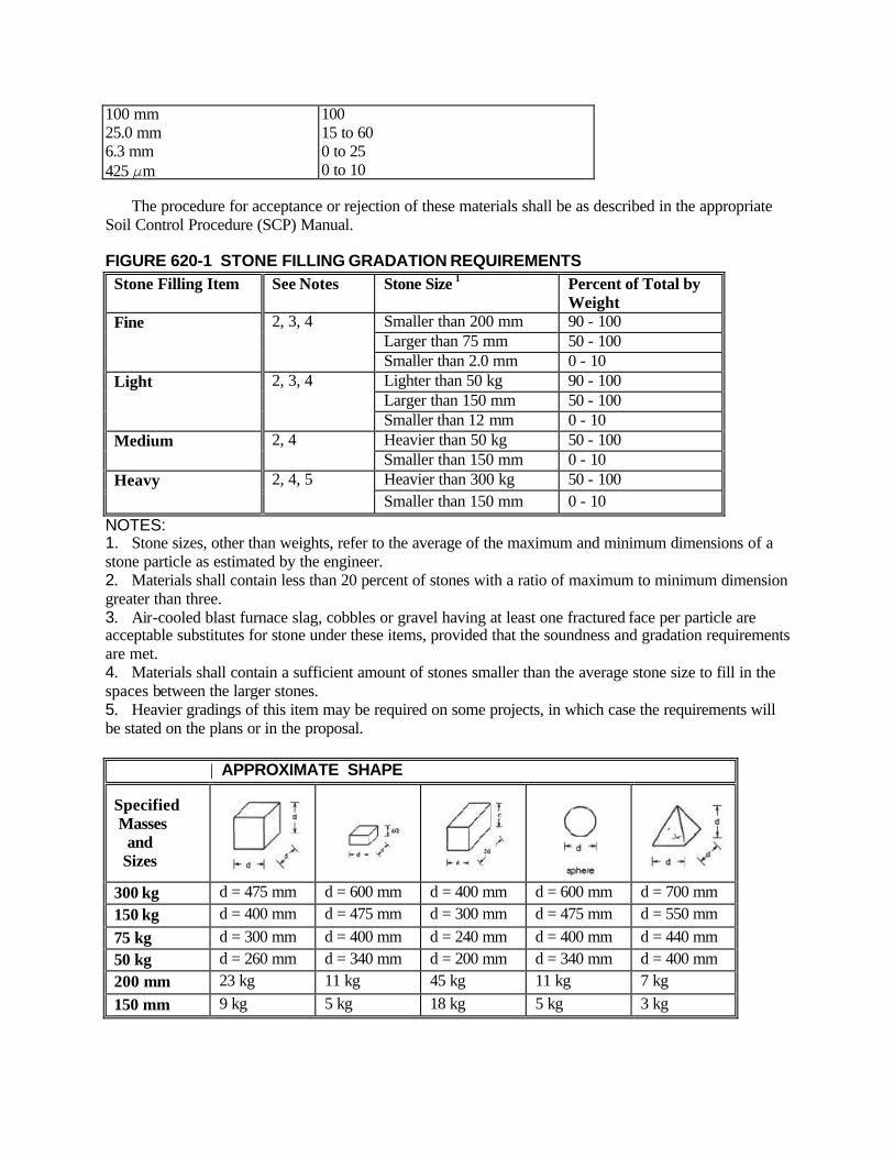
100 mm 25.0 mm 6.3 mm 425 Fm
100 15 to 60 0 to 25 0 to 10
The procedure for acceptance or rejection of these materials shall be as described in the appropriate Soil Control Procedure (SCP) Manual. FIGURE 620-1 STONE FILLING GRADATION REQUIREMENTS
Stone Filling Item See Notes Stone Size 1 Percent of Total by Weight
Smaller than 200 mm 90 - 100 Larger than 75 mm 50 - 100
Fine 2, 3, 4
Smaller than 2.0 mm 0 - 10 Lighter than 50 kg 90 - 100 Larger than 150 mm 50 - 100
Light 2, 3, 4
Smaller than 12 mm 0 - 10 Heavier than 50 kg 50 - 100 Medium 2, 4 Smaller than 150 mm 0 - 10 Heavier than 300 kg 50 - 100 Heavy 2, 4, 5 Smaller than 150 mm 0 - 10
NOTES: 1. Stone sizes, other than weights, refer to the average of the maximum and minimum dimensions of a stone particle as estimated by the engineer. 2. Materials shall contain less than 20 percent of stones with a ratio of maximum to minimum dimension greater than three. 3. Air-cooled blast furnace slag, cobbles or gravel having at least one fractured face per particle are acceptable substitutes for stone under these items, provided that the soundness and gradation requirements are met. 4. Materials shall contain a sufficient amount of stones smaller than the average stone size to fill in the spaces between the larger stones. 5. Heavier gradings of this item may be required on some projects, in which case the requirements will be stated on the plans or in the proposal.
| APPROXIMATE SHAPE
Specified Masses and Sizes
300 kg d = 475 mm d = 600 mm d = 400 mm d = 600 mm d = 700 mm 150 kg d = 400 mm d = 475 mm d = 300 mm d = 475 mm d = 550 mm 75 kg d = 300 mm d = 400 mm d = 240 mm d = 400 mm d = 440 mm 50 kg d = 260 mm d = 340 mm d = 200 mm d = 340 mm d = 400 mm 200 mm 23 kg 11 kg 45 kg 11 kg 7 kg 150 mm 9 kg 5 kg 18 kg 5 kg 3 kg
620-2.06 Concrete Block Paving. The concrete block shall comply with the requirements for Concrete Block (Slope Paving), §704-04. The block shall have the following nominal dimensions: Length: Thickness: Width:
400 to 500 mm 150 mm (solid) 200 mm
The standard dimensions of the block shall be the specified nominal dimension minus 10 mm. The maximum permissible variation in dimensions of individual units from standard dimensions shall be not more than 3 mm. The size of block used shall be consistent throughout any continuously paved area, and only one nominal length shall be used in any contract. All units shall be sound and free from cracks or other defects that would interfere with the proper placing of the blocks or impair the strength, permanence and appearance of the construction. Cushion sand for concrete block paving shall conform to the requirements for cushion sand set forth in §703-06. Grout, where used, shall consist of one part Portland Cement Type 2, conforming to the requirements of §701-01, and two parts Mortar Sand, conforming to the requirements of §703-03. 620-2.07 Gabions. The materials used in this work shall conform to the requirements of the following subsection of Section 700 - Materials. Gabions 712-15 620-3 CONSTRUCTION DETAILS 620-3.01 General. The ground surface on which bank or channel protection is to be placed shall be free of brush, trees, stumps, and other objectionable material and shall be dressed to a smooth surface. All soft or spongy material shall be removed to the depth shown on the plans or as directed by the Engineer and replaced with approved material. Filled areas shall be compacted in accordance with applicable provisions of §203-3.12, Compaction. Protection for structure foundations shall be provided as early as the foundation construction permits. The type of protection shall be placed in accordance with these specifications and the contract documents. 620-3.02 Stone Filling. Stone filling shall be placed in a manner that will produce a reasonable well-graded mass of stone with smaller stone fragments filling the space between the larger ones, so as to result in the minimum practicable percentage of voids. The final section of stone filling shall be in conformance with the lines, grades, and thicknesses shown on the plans. Stone filling used for bank or channel protection shall be placed to its full course thickness in one operation, unless otherwise directed by the Engineer or specified in the special provisions, and in such a manner that the underlying material will not be displaced or worked into the layer of stone filling. Placement of stone upon finished bedding material, when used, shall be carefully controlled to avoid disruption and damage to the layer of bedding material. The stone shall be so placed and distributed that there will be no pockets of uniform size material. The desired distribution of the various sizes of stone throughout the mass shall be obtained by selective loading of the material at the quarry or other source; by controlled dumping of successive loads during final placing; or by other methods of placement which will produce the specified results. Rearranging of individual stones by mechanical equipment or by hand will be required to the extent necessary to secure the specified results. When stone filling is dumped under water, methods shall be used that will minimize segregation. 620-3.03 Dry Rip-Rap. The stones shall be placed so that the dimension approximately equal to the layer thickness is perpendicular to the slope surface and that the weight of the stone is carried by the

underlying material and not by the adjacent stones. On slopes, the largest stones shall be placed at the bottom of the slope. The dry rip-rap shall be properly aligned and placed so as to minimize void spaces between the adjacent stones. The spaces between the stones shall be filled with spalls of suitable size. 620-3.04 Grouted Rip-Rap. The procedure of placing the stones shall be the same as described in §620-3.03, Dry Rip-Rap, except that the space between stones shall be filled with grout rather than spalls. Material upon which the grouted rip-rap is laid shall not be allowed to occupy the space between the stones. When the stones are in place, the spaces between them shall be completely filled with grout and the surface of the stones cleaned to remove accumulation of grout. Rip-rap shall not be grouted in freezing weather. The grouted rip-rap shall be kept moist for seven days after grouting. A suitable curing compound may be employed, if approved by the Engineer. The Engineer may direct that occasional spaces be left ungrouted for relief of hydrostatic pressure. The ungrouted spaces shall be chinked with spalls of suitable size. 620-3.05 Bedding Material. Where called for on the plans or directed by the Engineer, stone filling and dry rip-rap shall be placed on bedding material. The bedding material shall be placed on the prepared area to the full specified thickness of each layer in one operation, using methods which will not cause segregation of particle sizes. Contamination of bedding material by natural soils or other materials shall be prevented at all times. Bedding material that becomes contaminated shall be removed and replaced with uncontaminated bedding material at no expense to the State. 620-3.06 Concrete Block Paving. Blocks shall be laid on a 75 mm bed of cushion sand in running bond with the long dimension transverse to the slope and all joints tight. Blocks shall be thoroughly rammed in place to provide a uniformly even surface and solid bedding under each block. In the areas where grouting is called for, the concrete block shall be laid in running bond with the length parallel to the slope and with 6 mm joints. Following the laying of blocks, in the area to be grouted, sufficient mortar sand shall be spread over the surface and swept into the joints to fill the latter to 100 mm from the surface. The block shall be wetted to the satisfaction of the Engineer before any grout is placed. The joints shall be filled with grout from the bottom flush with the top of the block. After grouting has been completed and the grout has sufficiently hardened, the blocks shall be wetted, covered and cured with curing covers for the first seven days after grouting. Grout shall not be poured during freezing water. 620-3.07 Gabions. Each gabion unit shall be assembled by binding together all vertical edges with wire ties on approximately 150 mm spacing or by a continuous piece of connecting wire stitched around the vertical edges with a coil about every 100 mm. Empty gabion units shall be set to line and grade as shown on the plans. For structural integrity wire ties or connecting wire shall be used to join the gabions together along the perimeter of all contact surfaces according to the manufacturer's instructions. Internal tie wires shall be uniformly spaced and securely fastened in each outside cell of the structure in accordance with the manufacturer's instructions or where ordered by the Engineer. When gabions are being placed as slope protection the cross-connecting wire may be deleted if order by the Engineer. A standard fence stretcher, chain fall, or iron rod may be used to stretch the wire baskets and hold alignment. The gabions shall be filled with stone carefully placed by hand or machine to assure alignment and avoid bulges with a minimum of voids. After a gabion has been filled, the lid shall be bent over until it meets the side and edges. The lid shall then be secured to the sides, ends, and diaphragms with the wire ties or connective wire in the same manner described above for assembling. 620-4 METHOD OF MEASUREMENT

620-4.01 Stone Filling, Dry Rip-Rap, Gabions, Grouted Rip-Rap and Bedding Material. The quantity to be paid for under each of these items shall be the number of cubic meters computed from the payment lines shown on the plans, or as directed by the Engineer. 620-4.02 Concrete Block Paving. The quantity to be paid for under this item shall be the number of square meters computed from the payment liens shown on the plans, or as directed by the Engineer. 620-5 BASIS OF PAYMENT 620-5.01 Stone Filling, Dry Rip-Rap, Gabions, Grouted Rip-Rap and Bedding Material. The unite price bid per cubic meter for each of these items shall include the costs of furnishing all materials, labor and equipment necessary to satisfactorily complete the work, except that any necessary excavation will be paid for under its appropriate pay item. 620-5.02 Concrete Block Paving. The unit price bid per square meter for this item shall include the costs of furnishing all materials, labor and equipment necessary to satisfactorily complete the work, except that any necessary excavation will be paid for under its appropriate pay item. Payment will be made under: Item No. Item Pay Unit 620.02 M Stone Filling (Fine) Cubic Meter 620.03 M Stone Filling (Light) Cubic Meter 620.04 M Stone Filling (Medium) Cubic Meter 620.05 M Stone Filling (Heavy) Cubic Meter 620.06 M Dry Rip-Rap Cubic Meter 620.07 M Grouted Rip-Rap Cubic Meter 620.08 M Bedding Material Cubic Meter 620.09 M Concrete Block Paving Square Meter 620.10 M Galvanized Gabions Cubic Meter 620.11 M P.V.C. Coated Galvanized Gabions Cubic Meter SECTIONS 621 AND 622 (VACANT) SECTION 623 SCREENED GRAVEL, CRUSHED GRAVEL, CRUSHED STONE, CRUSHED SLAG 623-1 DESCRIPTION. This work shall consist of furnishing and placing, as shown on the plans or directed by the Engineer, screened gravel, crushed gravel, crushed stone, or crushed slag. 623-2 MATERIALS. The materials shall meet the requirements of §703-02, Coarse Aggregates, unless otherwise indicated, and shall be furnished in the sizes or combination of sizes indicated on the plans or ordered by the Engineer. 623-3 CONSTRUCTION DETAILS. Screened gravel, crushed gravel, crushed stone or crushed slag shall be placed on the plans or as directed by the Engineer. 623-4 METHOD OF MEASUREMENT

623-4.01 Measurement by Weight. The quantity to be paid for shall be the number of metric tons, loose measure, incorporated into the work conforming to the requirements of these specifications and in accordance with the lines, grades, and cross-sections shown on the plans or as directed by the Engineer. 623-4.02 In-Place Measure. The quantity to be paid for shall be the number of cubic meters of material placed, measured in the completed work, within the payment lines, as shown on the plans or as ordered by the Engineer. 623-5 BASIS OF PAYMENT. The unit price bid shall include costs of all labor, material and equipment necessary to properly complete the work. Payment will be made under: Item No. Item Pay Unit 623.01 M Screened Gravel (By Weight) Metric Ton 623.02 M Crushed Gravel (By Weight) Metric Ton 623.03 M Crushed Stone (By Weight) Metric Ton 623.04 M Crushed Slag (By Weight) Metric Ton 623.10 M Screened Gravel (In-Place Measure) Cubic Meter 623.11 M Crushed Gravel (In-Place Measure) Cubic Meter 623.12 M Crushed Stone (In-Place Measure) Cubic Meter 623.13 M Crushed Slag(In-Place Measure) Cubic Meter SECTION 624 - PAVED GUTTERS 624-1 DESCRIPTION. This work shall consist of the construction of asphalt concrete, precast, conventionally formed or machine formed Portland Cement concrete, or cobblestone gutters in accordance with these specifications and in reasonably close conformity with the lines and grades shown on the plans or established by the Engineer. 624-2 MATERIALS 624-2.01 Asphalt Concrete Gutters. The materials for hot mix asphalt gutters shall meet the requirements specified for a 9.5 mm mixture designed for <0.3 million ESALs using coarse aggregate Type F9. 624-2.02 Conventionally Formed Concrete Gutters. The materials and manufacture of concrete for this work shall meet the requirements for Class A concrete specified in Section 501 Portland Cement Concrete--General. 624-2.03 Precast Concrete Gutters. Precast concrete gutters shall comply with the requirements of §714-07, Precast Concrete Gutters. 624-2.04 Cobble Gutters. Cobble gutters shall be made of rounded “Hardheads,” 150 mm to 255 mm in diameter. 624-2.05 Machine Formed Concrete Gutter. The material requirements, mix preparation and manufacturing of concrete shall comply with the requirements for Class I concrete, as specified in Section 501 Portland Cement Concrete-General. 624-3 CONSTRUCTION DETAILS
624-3.01 Asphalt Concrete Gutters. Except as provided below, the construction requirements shall meet those of §402-3, Construction Details for Hot Mix Asphalt (HMA) Pavements. A. Preparation of Bed. The location of the gutter shall be properly excavated and graded to conform with the gutter cross-section and line and grade. The excavated area shall be firm and dry before laying the gutter. B. Placing. The asphalt concrete may be placed by handwork or by a paving machine approved by the Engineer. The gutter shall be uniform in texture, shape and density. The asphalt may be placed in a single layer providing that the section, line and grade after compaction are determined satisfactory by the Engineer. C. Sealing. After compaction, the finished surface of the gutter shall be sealed by an application of bituminous material, 702-3001, in the quantity and manner directed by the Engineer. 624-3.02 Conventionally Formed or Machine Formed Concrete Gutters. Concrete gutters shall be either conventionally formed or machine formed to the size and shape shown on the standard sheets. A. Conventionally Formed Gutters. 1. General. Unless otherwise indicated, concrete gutters shall be constructed in 2.4 m sections of the shapes and types shown on the plans and/or standard sheet. A steel separation plate 3 mm thick and cut to fit the section shall be used in each joint and removed as the concrete hardens. or the gutter may be constructed in alternate sections. 24 hours to elapse before the construction of the intermediate sections. Excess concrete shall be screeded off perpendicular to the line of the gutter. All construction joints shall be poured full with material meeting the requirements of 702-0700. Miscellaneous Asphalt Cement. 2. Curing. Curing of the gutters shall comply with the requirements of §502-3.11, Curing. Minimum curing periods for the various types of curing materials shall comply with the requirements of Table 502-3. A clear membrane curing compound may be used in lieu of a white-pigmented membrane. B. Machine Formed Gutter. The machine forming requirements of concrete curb as specified under §609-3.03 shall apply except that contraction joints shall be formed or scored every 2440 mm to depths sufficient to produce weakened planes in the concrete. 624-3.03 Precast Concrete Gutters. The location of the gutter shall be excavated and graded to conform with the gutter cross-section and line and grade. Gutter sections shall be placed to line and grade on a firm and dry subgrade. All joints shall be poured full with material meeting the requirements of 702-0700, Asphalt Filler. 624-3.04 Cobble Gutters. The largest stones shall be selected and set along the inner edge and the center of the gutter. All stones shall be embedded in mortar composed of one part Type 1 or 2 cement, §701-01, and two parts of §703-07, Concrete Sand. All stone shall be laid to line and grade, with close joints, by skilled workmen using regular paving tools. The stones shall then be thoroughly rammed in place and brought to a uniform surface. The joints shall be made of the same mortar as described above. The mortar shall completely fill the joints after being tamped. 624-4 METHOD OF MEASUREMENT

624-4.01 Asphalt Concrete Gutters. The quantity of asphalt gutters to be paid for will be measured by the number of metric tons of asphalt concrete furnished and placed in accordance with the plans, specifications and requirements of the Engineer. Quality payment adjustments will be measured as outlined in §402-4, Method of Measurement. 624-4.02 Conventionally Formed or Machine Formed Concrete Gutters. The quantity to be paid for under this work will be the number of square meters of exposed surface of concrete gutters placed in accordance with the plans and as specified by the Engineer. No reduction in the number of square meters will be made to account for drainage structure frames and grates, or any other obstruction placed within the gutter section. 624-4.03 Precast Concrete Gutters. The quantity to be paid for under this item will be the number of meters of gutter (laying length) placed in the work in accordance with the plans and specifications. 624-4.04 Cobble Gutters. The quantity of cobble gutters to be paid for under this work will be the number of square meters of exposed surface laid in accordance with the plans or as directed by the Engineer. 624-5 BASIS OF PAYMENT 624-5.01 Asphalt Concrete Gutters. The unit price bid per metric ton of asphalt concrete shall include the cost of furnishing all materials including the asphalt cement, the mixing, transporting, grading, placing, rolling and all equipment and labor necessary to complete the work including all necessary excavation below the finished surface, exclusive of any undercutting or excavation for special bedding materials. Payment of Quality Units will be made based on the Index Price listed in the contract documents. The index price shown in the itemized proposal for each Quality Unit shall be considered the price bid. The unit (index) price is not to be altered in any manner by the bidder. Should the bidder alter the amount shown, the altered figure will be disregarded and the original price will be used to determine the total amount bid for the Contract. 624-5.02 Conventionally Formed or Machine Formed Concrete Gutters. The unit price bid shall include the cost of furnishing all labor, materials and equipment necessary to complete the work including all necessary excavation below the finished surface exclusive of any undercutting or excavation for special bedding materials. 624-5.03 Precast Concrete Gutters. The provisions of §624-5.02 shall apply. 624-5.04 Cobble Gutters. The provisions of §624-5.02 shall apply. Payment will be made under: Item No. Item Pay Unit 624.01 624.01XX M Errata Conventionally Formed or Machine Formed
Concrete Gutters Square Meter 624.020101 M Asphalt Concrete Gutter Metric Ton 624.020110 M Plant Production Quality Adjustment to 624.020101 M Quality Unit “624.020601 M Asphalt Concrete Gutters, as Detailed Metric Ton 624.020610 M Plant Production Quality Adjustment to 624.020601 Quality Unit” Errata 1/16/03 “624.020601 M Asphalt Concrete Gutters, as Detailed Metric Ton
624.020611 M Plant Production Quality Adjustment to 624.020601 Quality Unit” Errata 1/15/04 624.03 624.03XX M Errata Precast Concrete Gutters Meter 624.0401 M Cobble Gutters Square Meter Refer to the Standard Contract Pay Item Catalog for full Item Number and full Description. SECTION 625 - SURVEY OPERATIONS, ROW MARKERS, & PERMANENT SURVEY MARKERS 625-1 DESCRIPTION 625-1.01 Project Survey and Stakeout. Under this work the Contractor shall do all necessary surveying required to construct all elements of the project as shown on the plans and specified in the proposal and specifications, and to protect all boundary and survey markers which are either shown on the plans or discovered on the project site. This work shall include but not be limited to stakeout, layout, and elevations for the highway, structures, forms, pile layouts and appurtenances as shown and required, consistent with the current practices of the Department, and shall be performed by competently qualified personnel acceptable to the Engineer. This shall also include all work necessary to preserve the location of all existing boundary or right of way and survey markers which should not be in direct conflict with the work to be performed under the contract, as well as all private property monumentation which is in direct conflict with the work to be performed under the contract. Where railroad relocation or alteration is done by force account by the railroad or by the Contractor, all necessary surveying is to be done as part of this work as directed by the Engineer. All survey stake-out shall proceed immediately following the award of the contract and shall be expeditiously progressed to completion in a manner and at a rate satisfactory to the Engineer. The Contractor shall keep the Engineer fully informed as to the progress of the stakeout survey. All survey control work shall be done in accordance with the Department’s “Surveying Standards & Procedures Manual”. 625-1.02 Right of Way Markers. Under this work, the Contractor shall locate, furnish, place and certify right-of-way markers at the locations indicated on the plans or where shown on right-of-way maps or where directed by the Engineer, in accordance with the details shown on the appropriate Standard Sheet, these specifications, and the directions of the Engineer. The Contractor shall verify with the Engineer, their use of the most current Right of Way Acquisition Maps to determine the appropriate locations of the proposed markers. 625-1.03 Permanent Survey Markers. Under this work the Contractor shall furnish and place permanent survey markers at locations indicated on the plans or as directed by the Engineer, and in accordance with the details shown on the appropria te standard sheet. 625-2 MATERIALS 625-2.01 Project Survey and Stakeout. All stakes, reinforcing steel, and any other material necessary to perform the work satisfactorily, shall be provided by the Contractor. All stakes used shall be of a type approved by the Engineer. All reinforcing steel shall be a minimum diameter 16 mm bar, 1 meter length, and Grade 300 or 420. It shall be the Contractor's responsibility to maintain stakes in their proper position and location at all times. 625-2.02 Concrete Right of Way Markers. Concrete right-of-way markers shall conform to the requirements of §712-05, Precast Concrete Right-of-Way Markers.
625-2.03 Steel Pin and Cap Right-of-Way Markers. Reinforcing steel used for the shank shall conform to ASTM A615, Grade 300 or Grade 420. It shall be epoxy coated for its entire length in accordance with the coating application requirements of §705-14 Longitudinal Joint Ties or §709-04 Epoxy Coated Bar Reinforcement, Grade 420. The cap shall be aluminum or a corrosion resistant aluminum alloy. The cap shall weigh a minimum of fifty grams and fasten to the shank by means of threading or force fitting. A commercial grade Silicone Sealant shall be used between the cap and the shank. Zinc Chromate Primer, §708-04 shall be applied to all aluminum or aluminum alloy surfaces to be in contact with cement concrete. Concrete Grouting Material §701-05 shall be used to anchor the Steel Pin and Cap Type Markers into rock. 625-2.04 Permanent Survey Markers. The concrete shall meet the requirements of Class A Concrete in Section 501, Portland Cement Concrete--General, except that the requirements for inspection facilities, automated batching controls and recordation do not apply. The batching, mixing and curing methods, and the inspection facilities shall meet the approval of the Department or its representative. The Contractor may submit, for approval by Director, Materials Bureau, a mix at least equivalent to the specified Class A Concrete. The cap shall be provided by the Contractor as specified by the standard sheet. 625-3 CONSTRUCTION DETAILS 625-3.01 Project Survey and Stakeout. The Contractor shall trim trees, brush and other interfering objects, not inconsistent with the plans, from survey lines in advance of all survey work to permit accurate and unimpeded work by its own stake-out survey crews and the Department's survey crews. The location and length shown on the plans for pipe and structural plate culverts shall be considered to be approximate. The ordered length of culverts will be determined by the Engineer after the Contractor accurately stakes the proposed culvert in the planned location as approved by the Engineer and after appropriate and necessary engineering study. The exact position of all work shall be established from survey control points which are shown on the plans and/or modified by the Engineer. Any error, apparent discrepancy or absence in or of data shown or required for accurately accomplishing the stake-out survey shall be referred to the Engineer for interpretation or furnishing when such is observed or required. The Contractor shall place two offset stakes or references at each center line station and at such intermediate locations as the Engineer may direct. From computations and measurements made by the Contractor, these stakes shall be clearly and legibly marked with the correct center line station number, offset and cut or fill so as to permit the establishment of the exact centerline location and elevation during construction. If markings become faded or blurred for any reason the markings shall be restored by the Contractor and at the request of the Engineer. The Contractor shall locate and place all cut, fill, slope, fine grade or other stakes and points, as the Engineer may direct for the proper progress of the work. All control points shall be properly guarded and flagged for easy identification. Drainage structures shall be staked out by the Contractor at the locations and elevations shown on the plans or specified by the Engineer. The Contractor shall also accurately establish the center line of bearings for bridge abutments and piers, by setting special hubs or reference points as directed by the Engineer, so located and protected to insure their remaining undisturbed until such time as they are no longer needed. The Contractor shall accurately mark the location of anchor bolts to be installed, establish the elevation of bearing surfaces and check bearing plates to insure installation at their exact elevation. Before the erection of structural steel is started the Contractor shall verify by accurate field measurements the locations, both vertically and horizontally, of all bearings and shall assume full responsibility for the fabricated structural steel fitting the substructure as constructed.
All required Rights-of-Way and easement limits shall be established, staked and referenced by the Contractor concurrent with the construction stake-out survey, and prior to any construction work beginning on the affected properties. Rights of way and easement limits shall only be set, and property lines reset, by or under the direction of a Licensed Land Surveyor or exempt Professional Engineer (as permitted under Section 7209(m) of the NYS Education Law), who is licensed and registered to practice in New York State. The Contractor shall supply proof to the Engineer that such work is being performed by or supervised by a Licensed Land Surveyor or exempt Professional Engineer and all control has been established in accordance with the Department’s “Surveying Standards & Procedures Manual”. Reference points, base lines, stakes and bench marks for borrow pits shall be established by the Contractor. As specified under §05-10 Survey and Stakeout, and §107-08 Preservation of Property, the Contractor shall ensure that prior to beginning work, all existing property line and survey monuments (including right of way markers) which are adjacent to work areas and may be disturbed during construction shall be properly tied into fixed reference points or located from prime project control, before beginning work in that area. Reference ties (3 or 4 minimum) or field location notes shall be neatly recorded and made available to the Engineer upon request. If any property line and/or survey monuments are disturbed by the Contractor, they shall be reset under this item prior to the conclusion of the contract by either reuse of the original marker or by use of reinforcing steel, as directed by the Engineer. All work connected with tying off monuments and/or resetting them shall be performed by or under the direction of a Professional Land Surveyor or exempt Professional Engineer, who is licensed and registered to practice in New York State. Information on installed right-of-way markers and permanent survey markers shall be neatly recorded on certification forms provided by the Engineer. The permanent survey marker forms include project information, as-built State Plane Coordinate values, control line and centerline station and offset to marker, distance and direction to adjacent markers, the elevation of the marker, and a sketch which shows the relative positions to the control line points, 3 or 4 physical ties to the markers, and a north arrow. The right of way marker forms include project information and control line (proposed and as-built) station and offset to the marker. The as-built location of all markers shall be recorded to the nearest millimeter and located from prime project control to a minimum accuracy of one part in twenty thousand. These locations shall be certified by a Professional Land Surveyor or exempt Professional Engineer who is licensed to practice in New York State. The certification forms shall be delivered to the Engineer within 30 calendar days of setting the markers, which then will be forwarded to the Regional Land Surveyor. The Contractor shall be responsible for the accuracy of the work and shall maintain all reference points, stakes, etc. throughout the life of the contract. Damaged or destroyed points, bench marks or stakes, or any reference points made inaccessible by the progress of the construction shall be replaced or transferred by the Contractor. Any of the above points, which may be destroyed or damaged shall be transferred by the Contractor before they are damaged or destroyed. All control points shall be referenced by ties (3 or 4 minimum) to acceptable objects and recorded. Any alterations or revisions in the ties shall be so noted and the information furnished to the Engineer immediately. All stake-out survey work related to highway control shall be referenced to the center line shown on the plans. All computations necessary to establish the exact position of the work from control points, shall be made and preserved by the Contractor. All computations, survey notes and other records necessary to accomplish the work shall be neatly made available to the Engineer upon request and shall become the property of the State and delivered to the Engineer not later than the date of acceptance of the contract. The Engineer may check all or any portion of the stake-out survey work or notes made by the Contractor. Any necessary correction to the work shall be made immediately by the Contractor. Such checking by the Engineer shall not relieve the Contractor of any responsibilities for the accuracy or completeness of the work. Prior to the final cross-section survey of the project by the Engineer, the Contractor shall reestablish center line or base line points and stationing as required by the Engineer.

Prior to the final cross-section survey of any borrow pits by the Engineer, the Contractor shall reestablish base line points and stationing, as well as any necessary bench marks as required by the Engineer. The Contractor will not be required or permitted to take the preconstruction or final cross-sections that are used for payment purposes. During the progress of the construction work the Contractor will be required to furnish all of the surveying and stake-out incidental to the proper location by line and grade for each phase of the work. For paving and any other operation requiring extreme accuracy, the Contractor will re-stake with pins or other acceptable hubs located directly adjacent to the work at a spacing directed by the Engineer. Just prior to completion of the contract, the Contractor shall reestablish if necessary and retie all control points as permanently as possible and to the satisfaction of the Engineer. 625-3.02 Right of Way Markers. The Contractor shall set right-of-way markers at the time the Engineer directs them to be placed. Placement shall be made from a closed traverse within Second-Order, Class II (1 part in 20,000) accuracy, and in accordance with the Department’s “Surveying Standards & Procedures Manual”. The right-of-way markers shall be set at the locations specified by the Engineer and as shown on the appropriate Right of Way Acquisition Maps. This work shall be performed by, or under the direction of, a Professional Land Surveyor or an exempt Professional Engineer who is licensed and registered to practice in New York State. The Licensed Land Surveyor or exempt Professional Engineer shall certify the as-built position of each marker on the appropriate form provided by the Engineer. The scheduling for installation of Right of Way Markers shall be approved by the Engineer prior to their installation. Right-of-Way markers shall be installed in accordance with the Standard Sheets, these specifications, and in accordance with the directions of the Engineer. If the Steel Pin ROW Marker is used, prior to placing the cap on the bar, the cap shall be filled 2/3 full of silicone sealant and then fastened to the bar by threading or by force fit. During the driving operation for the Steel Pin Right-of-Way Marker, the lettering on the cap shall be protected by the use of a metal sleeve or cushion block. The marker shall be driven so that the cap is flush with the ground surface. When located in rock, right-of-way markers shall be installed as shown on the Standard Sheet. For Steel Pin Right-of-Way Markers, the surface of the aluminum cap to be in contact with the concrete grout shall be thoroughly coated with §708-04 Zinc Chromate Primer or an alternate ma terial approved by the Materials Bureau. All right-of-way markers shall be properly guarded and flagged for easy identification during construction. The Contractor shall be responsible for maintaining and protecting right-of-way markers during construction. Any new or existing markers disturbed or damaged prior to contract acceptance shall be replaced by the Contractor at no expense to the State. 625-3.03 Permanent Survey Markers. The markers shall be constructed as shown on the applicable standard sheet and placed where directed by the Engineer. Upon completion of installation, the survey markers shall be located from a closed traverse within Second-Order , Class II (1 part in 20,000) accuracy, which has been established in accordance with the NYSDOT “Surveying Standards & Procedures Manual”. This work shall be performed by, or under the direction of, a Professional Land Surveyor or an exempt Professional Engineer licensed and registered in New York State. The Contractor shall provide the Engineer with completed forms which are certified by a Licensed Land Surveyor or exempt Professional Engineer and which lists the precise as-built location of each survey markers. Certification forms are available from the Engineer. The scheduling for installation of Survey Markers shall be approved by the Engineer prior to their installation. The sequential numbering required on the permanent survey marker caps is to coordinated with the Engineer and the Regional Land Surveyor. 625-4 METHOD OF MEASUREMENT

625-4.01 Project Survey and Stakeout. Payment will be made at the lump sum price bid for this work. Monthly payments will be made under this work in proportion to the amount of work done as determined by the Engineer. 625-4.02 Right of Way Markers. The number of right-of-way markers to be paid for under this work shall be the number placed and certified in accordance with the plans, right-of-way maps, or directions of the Engineer. Payment will be made upon proper installation of the marker, receipt of the certification form by the Engineer, and approval of the certification by the Regional Land Surveyor. 625-4.03 Permanent Survey Markers. The number of permanent survey markers to be paid for under this work shall be the number placed and certified, in accordance with the plans or as directed by the Engineer. Payment will be made upon proper installation of the marker, receipt of the certification form by the Engineer, and approval of the certification by the Regional Land Surveyor. 625-5 BASIS OF PAYMENT 625-5.01 Project Survey and Stakeout. The price bid shall include the cost of furnishing all labor, instruments, materials and equipment necessary to satisfactorily complete the work. 625-5.02 Right of Way Markers. The unit price bid per each shall include the cost of furnishing all labor, materials and equipment necessary to satisfactorily complete the work, except that all survey control necessary for stakeout and certification shall be included under the contract item for Survey and Stakeout. 625-5.03 Permanent Survey Markers. The unit price bid per each shall include the cost of furnishing all labor, materials, and equipment necessary to satisfactorily complete the work, except that all survey control necessary for stakeout and certification shall be included under the contract item for Survey and Stakeout. Payment will be made under: Item No. Item Pay Unit 625.01 M Survey and Stakeout Lump Sum 625.03 M Concrete Right-of-Way Markers Type H (High) Each 625.04 M Concrete Right-of-Way Markers Type L (Low) Each 625.05 M Steel Pin and Cap Right-of-Way Markers Each 625.06 M Permanent Survey Markers Each SECTIONS 626 THRU 629 (VACANT) SECTION 630 - BARRICADES 630-1 DESCRIPTION. This work shall consist of furnishing and erecting in accordance with the appropriate standard sheet, permanent type barricades for highway or highway-railroad installations at the locations indicated on the plans or as directed by the Engineer. 630-2 MATERIALS. Materials shall meet the requirements of the following subsections of §700 - Materials. Paint 708 Galvanized Steel Barrier Posts 710-14 Wood Posts 710-13 Corrugated Beam Guide Railing and Median Barrier 710-20

630-2.01 Barricades (All Permanent Types). Rails shall conform to §710-20 Corrugated Beam Guide Railing and Median Barrier, and to the details indicated on the appropriate standard sheet. Posts shall be steel W150 x 22 or wood 150 mm x 205 mm (nominal) as indicated in the proposal and in accordance with the details shown on the appropriate standard sheet for Highway Barrier and Highway Railroad Barricade. All metal posts shall conform to §710-14 Galvanized Steel Barrier Posts. Paint shall conform to the requirements specified in §708, Paints of the Standard Specifications. 630-3 CONSTRUCTION DETAILS 630-3.01 Barricades (All Permanent Types). Posts shall be set as shown on the plans, the applicable standard sheet, or as directed by the Engineer, and shall be set true to the line and grade and on a firmly tamped base. Rails shall be erected in such a manner as to produce a smooth appearance, and approximately parallel with the grade of the ground surface. Bolts shall be drawn tight and shall extend 6 mm to 12 mm beyond the nuts unless otherwise permitted by the Engineer. 630-4 METHOD OF MEASUREMENT 630-4.01 Barricades (All Permanent Types). The quantity to be measured for payment under this work will be the number of meters of barricade outside to outside of end posts plus an allowance of 1.2 m for each complete terminal assembly including all rails as specified on the plans. 630-5 BASIS OF PAYMENT 630-5.01 Barricades (All Permanent Types). The unit price bid per meter shall include the cost of all labor, equipment and material necessary to complete the work including inspection and testing information required as well as painting, excavating and backfilling. Any required signs will be paid for separately under the appropriate payment item. Payment will be made under: Item No. Item ` Pay Unit 630.01 M Barricade (Steel Posts) Meter 630.02 M Barricade (Wood Posts) Meter SECTION 631 (VACANT) SECTION 632 - CRIBBING 632-1 DESCRIPTION 632-1.01 General. This work shall consist of all the work required for furnishing and placing precast concrete cribbing or metal bin-type retaining walls including all excavation and filling in the manner specified by the contract documents or by the Engineer. Other types of cribbing not shown on the standard sheets may be furnished and placed, if approved by the D.C.E.S. 632-1.02 Definitions. The following general definitions shall be used in conjunction with this section: A. Unit. Any single piece used to construct precast concrete cribbing or metal bin-type retaining walls. For precast concrete cribbing the work unit shall include but not be limited to, stretchers, headers (both closed and open face), coping, bearing blocks, full sections, half sections, end sections, and leveling
footings. For metal bin-type retaining walls the word unit shall include, but not be limited to , stringers, spacers, columns, column caps, stringer stiffeners and base plates. B. Bin. Any volumetric space which is designated to be filled with backfilling material, as defined in this section, and is enclosed on all four sides by precast concrete cribbing units, or metal bin-type retaining wall units. C. Wall. A series of units to form bins connected in unbroken sequence so that, when filled with backfill material, they will act as a single entity (i.e., a retaining wall). 632-2 MATERIALS 632-2.01 Unit Materials. Materials shall meet the requirements specified in the following subsections of §700 - Materials: Precast Concrete Cribbing Metal Bin-Type Retaining Wall
704-06 715-11
Premoulded Resilient Joint Filler 705-07
632-2.02 Backfill. Backfill Material shall conform to the material requirements for either Stone Filling (Fine), as specified in §620-2.01 and 620-2.02, or Select Granular Fill and Select Structure Fill as specified in §203-2.01 and 203-2.02C. 632-3 CONSTRUCTION DETAILS 632-3.01 Precast Concrete Cribbing. A. Excavation. Excavation shall be conducted in accordance with the applicable requirements of Section 206, Trench, Culvert and Structure Excavation, and the details specified in the contract documents. Prior to erection of the cribbing, the foundation shall be inspected and approved by the Engineer. B. Erection. All units shall be assembled and handled in accordance with the manufacturer's instructions and the contract documents. In the event of a conflict between the contract documents and the manufacturer's instructions, the Engineer shall decide which course to follow. During erection, any units damaged beyond repair shall be removed and replaced, by the Contractor, with approved units. The Contractor shall use precast leveling footings. Cast-in-place leveling footings will not be permitted. C. Backfill. Immediately prior to backfilling, the Engineer shall inspect units for damage. Units, which are determined by the Engineer to be damaged beyond repair, shall be rejected. Rejected units shall be replaced by the Contractor. Filling the interior of the bins and behind the walls shall progress simultaneously with the erection of the units and the material shall be placed as specified in §203-3.15, Fill and Backfill at Structures, Culverts, Pipes, Conduits and Direct Burial Cables. D. Contractor Responsibility. Movement of construction equipment and all other vehicles and loads over and adjacent to walls shall be done at the Contractor's risk. Any damage to bins and units from any cause whatsoever shall be repaired or replaced by the Contractor in a manner satisfactory to the Engineer. 632-3.02 Metal Bin-Type Retaining Walls. The provisions specified in §632-3.01, Precast Concrete Cribbing, shall apply with the following additions and modifications:

The ends of all stringers and spacer units shall be bolted to corner columns by means of connecting channels. In the construction of a wall on a curve, the proper curvature for the face shall be obtained by the use of shorter stringers in the front or rear units of walls as designed on the plans or by the Engineer. The wall height and depth may be varied, but not to exceed the maximum dimension shown for the design selected. Two or more wall designs may be incorporated in the same wall by the use of standard split columns to make the connections on the step-back. 632-4 METHOD OF MEASUREMENT 632-4.01 Cribbing or Retaining Wall. Cribbing or retaining wall sha ll be measured by the number of square meters of the front wall face computed between the payment lines shown on the plans or between payment lines established, in writing, by the Engineer. 632-4.02 Excavation and Disposal of Excavated Material for the Installation of Cribbing or Retaining Wall. Excavation and disposal of excavated material shall be measured by the number of cubic meters of material measured in its original position between the payment lines shown on the plans or between payment lines established, in writing, by the Engineer. 632-4.03 Backfill for the Installation of Cribbing or Retaining Wall. Backfill shall be measured by the number of cubic meters of material, computed between the payment lines shown on the plans or between payment lines established in writing by the Engineer. Deductions for the volume of units of precast concrete cribbing will be made. No deduction will be made for the volume of a metal-bin unit. 632-5 BASIS OF PAYMENT 632-5.01 Cribbing or Retaining Wall. The unit price bid shall cover the cost of furnishing all materials, labor, and equipment necessary to complete the work including leveling footings required for precast concrete wall units, and the replacement or repair of any materials damaged by the Contractor's operations. 632-5.02 Excavation and Disposal of Excavated Material for the Installation of Cribbing or Retaining Wall. The unit price bid shall include the cost of all labor, material and equipment necessary to complete the work. 632-5.03 Backfill for the Installation of Cribbing or Retaining Wall. The unit price bid shall include the cost of all materials, labor, and equipment necessary to complete the work. No direct payment will be made for any loss of material which may result from compaction, foundation settlement, erosion, or any other cause; the cost of such losses shall be included in the price bid for this work. The cost of adding water for compaction of backfill shall be included in the price bid unless the item “Applying Water” is included in the proposal. Payment will be made under: Item No. Item Pay Unit 632.0101 M Concrete Cribbing (Stretcher and Header Type) Square Meter 632.0102 M Concrete Cribbing (Precast Concrete Wall Unit Type) Square Meter 632.02 M Metal Bin-Type Retaining Wall Square Meter 632.0501 M Excavation for Concrete Cribbing (Stretcher and Header Type) Cubic Meter 632.0502 M Excavation for Concrete Cribbing(Precast Concrete Wall Unit Type) Cubic Meter 632.0503 M Excavation for Metal Bin-Type Retaining Wall Cubic Meter 632.0601 M Backfill for Concrete Cribbing (Stretcher and Header Type) Cubic Meter

632.0602 M Backfill for Concrete Cribbing (Precast Concrete Wall Unit Type) Cubic Meter 632.0603 M Backfill for Metal Bin-Type Retaining Wall Cubic Meter SECTION 633 - CONDITIONING EXISTING PAVEMENT 633-1 DESCRIPTION. This work shall consist of cleaning, sealing and filling joints and cracks in the existing pavement and cleaning the existing pavement prior to the application of a new course. Shoulders are to be cleaned when they are to be overlaid. 633-2 MATERIALS. The materials shall conform to the requirements of the specifications listed below: Hot Mix Asphalt (HMA) Pavements Bituminous Materials Asphalt Filler
402 702 702-0700
Fine Aggregate Coarse Aggregate Mineral Filler
703-01 703-02 703-08
633-3 CONSTRUCTION DETAILS 633-3.01 Cleaning Existing Pavement and/or Shoulders. Existing pavement and shoulder surfaces to be overlaid, including ruts and depressions, shall be cleaned by the use of mechanical sweepers, hand brooms, or other effective means until the surfaces are free of all material which might interfere with the bond between the overlay material and the existing surfaces. All cleaning equipment shall be approved by the Engineer prior to use. Cleaning shall continue until adequate cleaning results, as determined by the Engineer. All debris shall be removed from the pavement and shoulders surfaces and disposed of in a manner directed by the Engineer. The pavement and shoulders shall be kept clean until the overlay operations are completed. Cleaning of shoulders is required only when the shoulder surface is constructed of Portland Cement, asphalt concrete or a surface treatment thereon. 633-3.02 Cleaning, Sealing and Filling Joints and Cracks. All unsealed and inadequately sealed joints and cracks, as determined by the Engineer, shall be subjected to a compressed air stream of at least 550 kPa measured at the source. Joints and cracks in the pavement as designated by the Engineer, shall be cleaned of all dirt and loose material holding the cleaning jet 25 mm above the pavement surface. Old joint and crack sealer remaining after such cleaning operation need not be removed. The cracks shall be kept clean until the sealing, filling and paving operations are completed. Joints and cracks in the existing pavement from 6 mm to 25 mm wide shall be sealed with a bituminous material meeting the requirements of §702-0700, Asphalt Filler. To insure that space will be available for expansion of the asphalt when the hot bituminous mixture is paved over the joint or crack, the joint or crack shall not be filled completely to the surface. Blotting with fine aggregate may be required by the Engineer to prevent tracking the bituminous material over the pavement surface. Joints and cracks greater than 25 mm wide shall be filled with asphalt concrete meeting the requirements of Section 402 or a Department approved cold plant mixed stockpile patching material. Alternate materials may be used subject to the approval of the Engineer. Joints and cracks less than 6 mm will not be required to be cleaned or sealed. Work on joints and cracks shall not begin until all stress relieving pavement repairs have been completed. 633-4 METHOD OF MEASUREMENT 633-4.01 Cleaning Existing Pavement and/or Shoulders. The quantity to be measured shall be the actual number of square meters of existing pavement and/or shoulder surfaces cleaned.

633-4.02 Cleaning, Sealing and Filling Joints and Cracks. The quantity measured will be on a lump sum basis for work satisfactorily completed in a manner approved by the Engineer. 633-5 BASIS OF PAYMENT 633-5.01 Cleaning Existing Pavement and/or Shoulders. The unit price bid per square meter for this work shall include the cost of all labor, materials and equipment necessary to complete the work. 633-5.02 Cleaning, Sealing and Filling Joints and Cracks. The lump sum price bid for this item shall include the cost of all labor, materials and equipment necessary to complete the work. Payment will be made under: Item No. Item Pay Unit 633.0202 M Cleaning Existing Pavement and/or Shoulders Square Meter 633.05 M Cleaning, Sealing and Filling Joints and Cracks Lump Sum SECTION 634 (VACANT) SECTION 635 - CLEANING AND PREPARATION OF PAVEMENT SURFACES FOR PAVEMENT MARKINGS 635-1 DESCRIPTION. This work shall consist of cleaning and preparing portland cement and bituminous pavement surfaces for the application of reflectorized pavement marking materials. Examples of pavement markings requiring this item include, but are not limited to, reflectorized thermoplastic, preformed, and epoxy type marking materials. 635-2 MATERIALS. Materials and equipment for cleaning and preparing pavement surfaces may be selected by the Contractor, except that they will be approved by the Engineer and shall conform to all applicable Local, State or Federal law, regulation or codes. 635-3 CONSTRUCTION DETAILS 635-3.01 General. The work required to clean and prepare pavement surfaces shall be performed in accordance with these specifications, the contract documents and to the satisfaction of the Engineer. Before any work is begun, a schedule of operations shall be submitted for the approval of the Engineer. When the work is conducted under traffic, the Contractor shall supply all necessary flags, markers, signs, and other devices to maintain and protect traffic. Whenever grinding, waterblasting, dry sandblasting or other operations are performed, the work shall be conducted in such a manner that the finished pavement surface is not damaged or left in a pattern that will mislead or misdirect the motorist. When these operations are completed the pavement surface shall first be power broomed and then blown off with compressed air to remove residue and debris resulting from the cleaning work. All such debris that remains on the roadway, including broken parts from cleaning equipment, shall be removed and disposed of in a manner satisfactory to the Engineer. The Contractor shall conduct removal and cleaning work in such a manner as to minimize airborne dust, and similar debris so as to prevent a hazard to motor vehicle operation or nuisance to property. Care shall be taken on bituminous and portland cement concrete surfaces when performing removal and cleaning work to prevent damage to transverse and longitudinal joint sealers.
Unless otherwise specified in the contract documents the area(s) and quantity of cleaning work will be determined by the Engineer at the job site when the contract is in progress. In addition the Engineer will have the authority of increasing the work area as the project continues. 635-3.02 Limits of Work. Cleaning and surface preparation work shall be confined to the surface area specified for the application of pavement marking materials; or the surface area of existing pavement markings that are specified for removal on the plans, or as directed by the Engineer. Surface preparation work includes cleaning for lines or cleaning for letters and symbols. Lines will be meant to include: broken line; dotted line; channelizing line; barrier lines; stop lines; crosswalk line and crossbars. When lines are cleaned, the area of preparation will be the width of the new pavement marking, or existing line, plus twenty five (25) millimeter on each side. When letters and symbols are cleaned the area of preparation will be sufficiently large to accommodate the new marking, or to remove the existing marking. 635-3.03 Cleaning Concrete Curing Compounds. On new portland cement concrete pavements, cleaning operations shall not begin until a minimum of 30 days after the placement of concrete. All new concrete pavements shall be cleaned by either sandblasting or water blasting. When water blasting is performed, pavement markings shall be applied no sooner than 24 hours after the blasting has been completed. The extent of the blasting work shall be to clean and prepare the concrete surface such that: A. There is no visible evidence of curing compound on the peaks of the textured concrete surface. B. There are no heavy puddled deposits of curing compound in the valleys of the textured concrete surface. C. All remaining curing compound is intact; all loose and flaking material is removed. D. The peaks of the textured pavement surface are rounded in profile and free of sharp edges and irregularities. 635-3.04 Cleaning Existing Pavement Markings. Existing pavement markings shall be cleaned for the purpose of: A. Preparing the pavement surface for the application of new pavement markings in the same location as the existing markings. B. To remove existing markings that are in good condition which, if allowed to remain, will interfere with or otherwise conflict with newly applied marking patterns. It shall be understood that in this context cleaning means the removal of an existing marking. It is not intended that all deteriorated existing pavement markings be removed. Example: If a new marking is applied to an unmarked “gap” in a broken line and the existing broken line pattern is worn or deteriorated, as determined by the Engineer, to the extent that it is not misleading or confusing to the motorist, the existing markings do not require removal. Pavement markings shall be cleaned to the extent that 95% to 100% of the existing marking is removed. Removal operations shall be conducted in such a manner that no more than moderate color and/or surface texture change results on the surrounding pavement surface. When waterblasting is performed, pavement markings shall be applied no sooner than 24 hours after the blasting has been completed. Waterblasting shall not be allowed for cleaning markings requiring replacement within the same day as removal as specified under §635-3.05.
The determination of acceptable removal will be made by judgement of the Engineer and will be guided by the Department's pictorial standards of acceptable marking removal. Pictorial standards are available from the Materials Bureau. 635-3.05 Replacement of Pavement Markings. The Contractor shall not remove existing pavement markings and leave the highway unmarked overnight. If traffic is to be maintained overnight on highways where the existing markings have been removed either the permanent type marking(s) as called for in the contract documents, or short–term pavement markings, shall be applied before the end of the working day for the following conditions. 1. Yellow broken lines, partial barrier lines and full lines used to separate opposing traffic flows on two–way roadways. 2. White broken lane lines to separate traffic flows in the same direction on multi–lane highways. In the event of sudden, unforeseen precipitation or other extraordinary situations, Do Not Pass signs shall be used on two or three lane, two–way roadways, in accordance with §619–3.06 Short–Term Pavement Markings. All other pavement marking patterns on both two way and multi–lane highways shall be applied within 14 calendar days using the project's permanent markings. The Contractor may apply the permanent white and yellow broken line in the gaps between the existing broken line, before the existing broken line is removed, when the Engineer determines that the existing broken line will not be misleading to traffic. If short–term pavement markings are placed, they shall be applied and conform to the requirements of §619–3.06. Short–term Pavement Markings will be considered acceptable for periods not longer than fourteen (14) days. If within 14 days after removal the Contractor fails to install the project's permanent pavement markings, temporary pavement markings shall be applied and maintained in accordance with §619–3.06 Short–term Pavement Markings. All short–term and temporary pavement markings shall be cleaned from the pavement in accordance with this specification, at the time that the project's permanent markings are installed, or as directed by the Engineer. Signs shall be removed as ordered by the Engineer. The work of furnishing, applying, maintaining and cleaning short-term and temporary markings shall be performed by the Contractor at no additional expense to the State. 635-4 METHOD OF MEASUREMENT. Surface cleaning and preparation of pavement surfaces for lines will be measured in meters along the centerline of the prepared surface and will be based on a nominal 100 mm wide line. Measurement for cleaning surfaces for line widths greater than the nominal 100 mm will be made by the following method: Nominal Existing Width of Line (millimeters) x Length (meters) 100 (millimeters) No payment will be made for the additional 25 mm of cleaning on each side of the line required by §635-3.02. No payment will be made for cleaning the number of meters of unmarked gaps between broken or dotted line segments. Cleaning and preparation of letters and symbols on pavement surfaces will be measured by each unit cleaned. A unit will consist of one letter or one symbol. Example: “STOP” would be measured as four units. The Engineer will adjust the quantities of these items as required to meet field conditions. This may result in substantial increases or decreases of the proposal quantities.

635-5 BASIS OF PAYMENT. The accepted quantities of cleaned pavement surface will be paid for at the contract unit price, which shall include the cost of furnishing all labor, materials and equipment to satisfactorily complete the work. The cost of maintaining and protecting traffic during the cleaning work will be included in the price bid. No payment will be made under this item for the removal of pavement markings required under §635-3.05. Payment will be made under: Item No. Item Pay Unit 635.0103 M Cleaning and Preparation of Pavement Surfaces-Lines Meter 635.0203 M Cleaning and Preparation of Pavement Surfaces-Letters Each 635.0303 M Cleaning and Preparation of Pavement Surfaces-Symbols Each SECTION 636 (VACANT) SECTION 637 - ENGINEER'S OFFICE AND LABORATORY BUILDING 637-1 DESCRIPTION. This work shall consist of providing, furnishing and maintaining an Engineer's Office and a Field Laboratory Building for the exclusive use of and occupancy by the Department and Consultant field engineers. It shall be the responsibility of the Contractor to install and maintain the Engineer's Office in compliance with all applicable building, safety, and health regulations and/or laws. The Contractor shall maintain all facilities and furnished equipment in good working condition. The office shall be cleaned weekly, or as required by the Engineer. 637-1.01 Engineer's Office (Type A, B, C, D or E). The Contractor shall supply for the Engineer's use a building or mobile trailer, (specified at Type A, B, C, D or E), which shall be erected at a location selected by the Engineer and shall be separate from any building used by the Contractor. 637-1.02 Laboratory Building. The Contractor shall supply mobile building(s) or trailer(s) for use as field laboratories for soils and materials testing. As work progresses on the contract, the laboratory shall be moved by the Contractor to follow the work, at such times and to the locations approved or designated by the Engineer. 637-1.03 Furnishing Existing Facilities and Buildings. The Contractor may furnish equivalent facilities in existing buildings provided such facilities and building(s) are located to provide convenient service and provided that the building location(s) and facilities are approved by the Regional Director in writing. 637-1.04 Concrete Cylinder Curing Box. This work shall consist of furnishing, prior to placement of any structural concrete, an approved concrete cylinder curing box. 637-2 MATERIALS 637-2.01 General Construction. Each Engineer's Office or Field Laboratory shall be an approved and weatherproof building or mobile trailer of the type specified in the contract documents. The structure shall have a minimum ceiling height of 2.13 meters and shall be provided with weatherproof windows and weatherproof doors each equipped with adequate locking devices. Each window shall have a minimum area of 0.75 square meters, shall be screened and of a type that will open and close to provide adequate ventilation. 637-2.02 General Requirements for all Engineer's Offices.

A. Lighting. Electric light, non-glare type luminaires to provide a minimum illumination level of 1000 lux at desk height level. B. Heating and Cooling. Adequate equipment to maintain an ambient air temperature of 21EC "3E. C. 35mm Camera. Autofocus operation with “red-eye reduction” and “easy film loading” features. A soft storage/carry case shall be provided. The camera functions shall include the following. Automatic and motorized film advance and rewind Automatic adjustment for DX coded films Film speeds ISO 100 through 400 Built in flash with automatic sensor Date stamp on each picture The supply of batteries shall be replenished by the Contractor as required by the Engineer. Film and film processing will be the responsibility of the State. D. Typewriter with stand. A standard electric office size with pica type and a stand with casters. E. Telephone. A separate phone for the exclusive use of Department and Consultant personnel. The phone shall have modular jacks at the wall and phone and be adaptable to electronic communications. An extension telephone, of a type and location as required by the Engineer, with a minimum 7 meter cord shall also be provided. The number of telephones, each with an extension, to be provided is specified for each type of office. F. Potable Water. From a local municipal water line and/or bottled water with refrigerator unit - hot/cold water. G. Adding Machine. Tape type registering to at least ten digits, four function. The number of adding machines to be provided is specified for each type of office. H. First Aid Kit. The Contractor shall keep the kit properly stocked with appropriate first aid supplies at all times. I. Toilet. A separately enclosed room, properly ventilated and complying with applicable sanitary codes. The Contractor shall provide all lavatory amenities, necessary paper and soap products, hot and cold running water and a flush-type toilet. Any other toilet will not be acceptable unless as ordered by the Engineer (A.O.B.E.). J. Locker. A metal or wood locker, with lock, of sufficient size for storage of surveying instruments and testing equipment. K. Refrigerator. A standard electric cold storage type providing a minimum storage space of approximately 0.09 m3. L. Fire Extinguisher. Non-toxic dry chemical, fire extinguisher meeting Underwriters Laboratories, Inc., approval for Class A, Class B and Class C fires with a minimum rating of 2A: 10B: 10C. 1 per room.
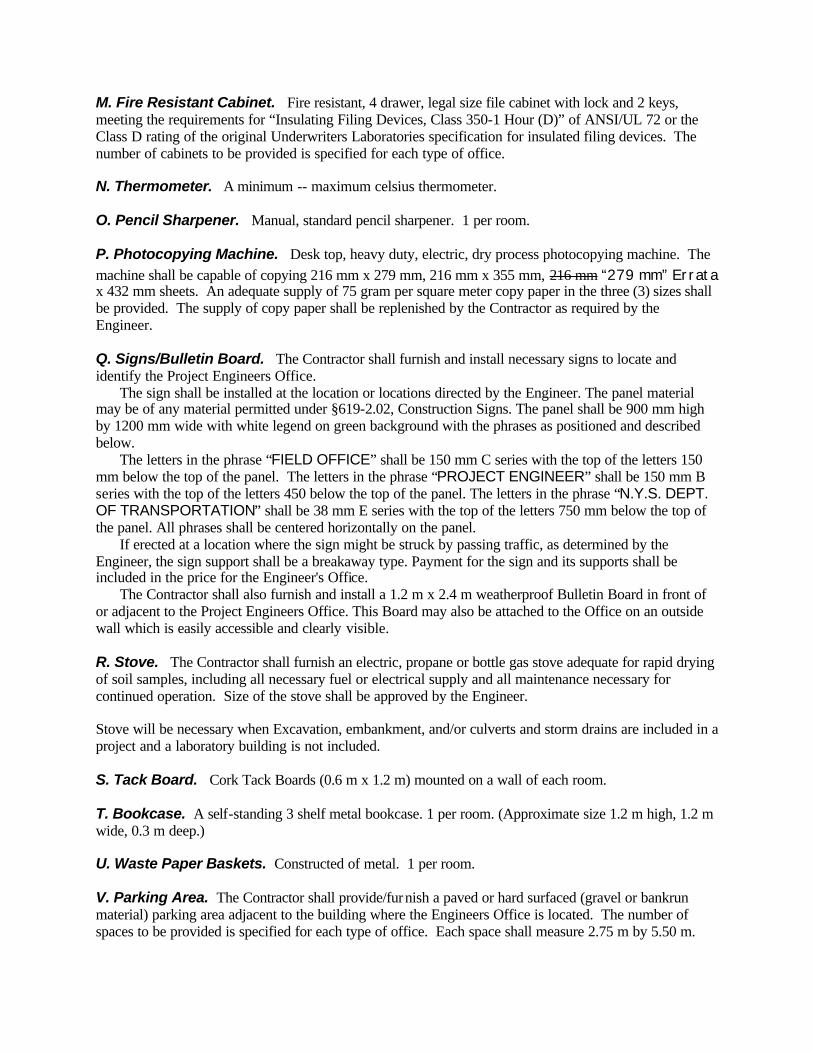
M. Fire Resistant Cabinet. Fire resistant, 4 drawer, legal size file cabinet with lock and 2 keys, meeting the requirements for “Insulating Filing Devices, Class 350-1 Hour (D)” of ANSI/UL 72 or the Class D rating of the original Underwriters Laboratories specification for insulated filing devices. The number of cabinets to be provided is specified for each type of office. N. Thermometer. A minimum -- maximum celsius thermometer. O. Pencil Sharpener. Manual, standard pencil sharpener. 1 per room. P. Photocopying Machine. Desk top, heavy duty, electric, dry process photocopying machine. The machine shall be capable of copying 216 mm x 279 mm, 216 mm x 355 mm, 216 mm “279 mm” Errata x 432 mm sheets. An adequate supply of 75 gram per square meter copy paper in the three (3) sizes shall be provided. The supply of copy paper shall be replenished by the Contractor as required by the Engineer. Q. Signs/Bulletin Board. The Contractor shall furnish and install necessary signs to locate and identify the Project Engineers Office. The sign shall be installed at the location or locations directed by the Engineer. The panel material may be of any material permitted under §619-2.02, Construction Signs. The panel shall be 900 mm high by 1200 mm wide with white legend on green background with the phrases as positioned and described below. The letters in the phrase “FIELD OFFICE” shall be 150 mm C series with the top of the letters 150 mm below the top of the panel. The letters in the phrase “PROJECT ENGINEER” shall be 150 mm B series with the top of the letters 450 below the top of the panel. The letters in the phrase “N.Y.S. DEPT. OF TRANSPORTATION” shall be 38 mm E series with the top of the letters 750 mm below the top of the panel. All phrases shall be centered horizontally on the panel. If erected at a location where the sign might be struck by passing traffic, as determined by the Engineer, the sign support shall be a breakaway type. Payment for the sign and its supports shall be included in the price for the Engineer's Office. The Contractor shall also furnish and install a 1.2 m x 2.4 m weatherproof Bulletin Board in front of or adjacent to the Project Engineers Office. This Board may also be attached to the Office on an outside wall which is easily accessible and clearly visible. R. Stove. The Contractor shall furnish an electric, propane or bottle gas stove adequate for rapid drying of soil samples, including all necessary fuel or electrical supply and all maintenance necessary for continued operation. Size of the stove shall be approved by the Engineer. Stove will be necessary when Excavation, embankment, and/or culverts and storm drains are included in a project and a laboratory building is not included. S. Tack Board. Cork Tack Boards (0.6 m x 1.2 m) mounted on a wall of each room. T. Bookcase. A self-standing 3 shelf metal bookcase. 1 per room. (Approximate size 1.2 m high, 1.2 m wide, 0.3 m deep.) U. Waste Paper Baskets. Constructed of metal. 1 per room. V. Parking Area. The Contractor shall provide/furnish a paved or hard surfaced (gravel or bankrun material) parking area adjacent to the building where the Engineers Office is located. The number of spaces to be provided is specified for each type of office. Each space shall measure 2.75 m by 5.50 m.

W. Mailbox. Standard mailbox (with post if necessary) or post office box shall be provided. X. Coat Rack. A metal or wooden coat rack capable of holding at least 4 coats. 1 per room. Y. Telephone Answering Device. A FCC approved automatic answering device capable of recording outgoing messages of 60 seconds long and receiving a minimum of 40 incoming messages of 60 seconds duration. The unit shall include a message mark so you can hear new messages without erasing old messages. The unit shall include remote programming of playback, backspace, and out-going message re-record. The unit shall include computer generated voice marking of time and day of each message received. The unit shall allow for the retrieval of messages without a remote beeper unit or shall include a number of remote control units as ordered by the Engineer (A.O.B.E.). Z. Telephone FAX Machine, with a dedicated telephone line (in addition to the telephone line(s) specified in Table 637-1 and meeting the following requirements: DOCUMENT SIZE 216 mm X 279 mm both transmit and receive with
transmit speed less than 20 seconds per page COMPATIBILITY Group G3 RESOLUTION Standard, with 16-Shade Gray Scale RECEIVING Automatic DOC FEEDER Automatic 5 Sheets AUTO DIALER 10 Phone Number Memory with automatic redial and
on-hook dialing TRANSMIT TERMINAL IDENTIFICATION
Page number, Sender's Phone Number and Name
OUTPUT DOCUMENT SEPARATOR Automatic Cutter
An adequate supply of fax paper shall be provided. The supply of fax paper shall be replenished by the Contractor as required by the Engineer. 637-2.03 General Requirements for Engineer's Offices, Types B, C, D and E only (Not Type A) 1. Freestanding Microcomputer System Workstation with a 1.50 m long by 0.75 m wide work surface and height of 0.70 m. The workstation shall include an adjustable shelf approximately 0.30 m wide and no less than 0.75 m long. This workstation shall be fully assembled. 2. Ergonomic Microcomputer Workstation Chair w/arms, five (5) legs w/casters and adjustable from approximately 0.4 m to 0.6 m height by pneumatic gas cylinder. This chair shall be fully assembled. 3. Antistatic Tabletop Mat for the Microcomputer System Workstation with an approximate size of 0.75 m long by 0.60 m wide. 4. Ergonomic and height adjustable “wrist rest” keyboarding support 5. Calculator. The device shall be capable of executing normal engineering/surveying calculations and have sufficient memory to accept and execute programs of at least 200 lines or steps. The device shall also be capable of printing the results of calculations and programs, storing programs resident in the device on a magnetic medium for later use, and accepting preprogrammed software. The Contractor shall supply the preprogrammed software capable of performing normal surveying computations and the printing paper. The supply of printing paper shall be replenished by the Contractor as required by the Engineer. Instruction manuals for the calculator and software shall also be provided.

637-2.04 Specific Requirements for all Engineer's Offices (Type A, B, C, D, and E). A. Engineer's Office Type A. In addition to the general requirements, Type A shall provide a minimum of 18 square meters of floor space with one outside door and four windows. The office shall be partitioned to provide two rooms with an adjoining door. The smaller room shall not be less than 6 square meters in floor area and shall contain at least one of the four windows. The furnishings shall be as indicated in Table 637-1 of this Section. B. Engineer's Office Type B. In addition to the general requirements, Type B office shall provide a minimum 30 square meters of floor space with two outside doors and six windows. The office shall be partitioned to provide two rooms with an adjoining door. The smaller room shall be not less than 9 square meters in floor area and shall contain two of the six windows. The furnishings shall be as indicated in Table 637-1 of this Section. C. Engineer's Office Type C. In addition to the general requirements, Type C office shall provide a minimum 42 square meters of floor space with two outside doors and six windows. The office shall be partitioned to provide three rooms with adjoining doors. The smaller rooms shall be not less than 9 square meters in floor area and shall contain two of the six windows. The furnishings shall be as indicated in Table 637-1 of this Section. D. Engineer's Office Type D. In addition to the general requirements, Type D office shall provide a minimum of 66 square meters of floor space and shall be partitioned to provide four rooms: three small rooms and one large room with adjoining doors. The smaller rooms shall be not less than 9 square meters in area, and shall each contain two windows. Two outside doors and at least eight windows will be the total required. The furnishings shall be as indicated in Table 637-1 of this Section. If two mobile trailer units are provided, they shall be joined in parallel fashion and shall have two weatherproof doorways or archways between units A.O.B.E. A minimum of two (2) outside doors shall still be required, and arranged so as to facilitate emergency access. TABLE 637-1 SPECIFIC REQUIREMENTS FOR OFFICES
Office Type A B C D E Item Description # # # # # Office Desks not less than 0.75 m X 1.5 m each with Drawers and Locks 1 3 4 7 8
Office Chairs 4 6 8 16 18 Fire Resistant Cabinet, 4-Drawer as specified in §637-2.02M 1 2 3 4 6 Drafting-type Tables, approximately 0.9 m by 1.8 m and supported by brackets and legs 1 2 2 3 4
Drafting stools 2 4 4 6 8 Vertical filing plan rack for 6 sets of plans each 1 0 0 0 0 Vertical filing plan rack for 12 sets of plans each 0 1 1 2 3 Roll File Unit each with twelve 0.15 m X 0.15 m compartments for twelve cross-section rolls each 0.60 meters long 0 1 1 1 2
Office table, not less than 0.9 m X 1.8 m each 1 1 2 3 4 Metal storage cabinet with four adjustable shelves, tumbler lock and two keys (approx. size 1.80 m high, 0.90 m wide, 0.45 m deep) 0 1 1 1 2
Adding Machine as specified in §637-2.02G 1 1 2 2 3 Telephone lines with extensions as specified in §637-2.02E 1 1 2 2 2 Parking lot spaces as specified in §637-2.02V 5 5 6 8 10

E. Engineer's Office Type E. In addition to the general requirements, Type E office shall provide a minimum of 85 square meters of floor space, a maximum of 130 square meters of floor space, and shall be partitioned to provide four rooms: two small rooms and two large rooms each with adjoining doors. The smaller rooms shall be not less than 11 square meters in area and shall each contain two windows. Two outside doors and at least twelve windows will be required. The furnishings shall be as indicated in Table 637-1 of this Section. If two mobile trailer units are provided, they shall be joined in parallel fashion and shall have two weatherproof doorways or archways between units A.O.B.E. A minimum of two (2) outside doors shall still be required, and arranged so as to facilitate emergency access. 637-2.05 Minimum requirements for Field Laboratories. A. Area. Floor space of 9 square meters. B. Windows. Three windows. C. Doors. One door with lock and two sets of keys. D. Floor Covering. Linoleum, tile or other serviceable finish. E. Sink. A sink at least 0.90 meters long by 0.60 meters wide by 0.45 meters deep, equipped with water faucet and drain line. F. Counter. A work counter next to sink at least 0.6 meters long by 0.6 meters wide. G. Table. A heavy duty work table not less than 2.50 meters long by 0.75 meters wide by 0.90 meters high. H. Cabinet. A storage cabinet or locker at least 0.6 meters square by 1.8 meters high, equipped with at least four shelves, lock and two keys. I. Fire Resistant Cabinet. Two drawer as specified in §637-2.02M. J. Desk. A desk or writing table with chair. K. Pedestal. A heavy wooden block for soil compaction tests, nominally 0.25 meters square by 0.30 meters high. (Soils Lab. only.) L. Stove. As specified in §637-2.02R. M. Lighting. Electric lighting and not less than three convenient outlets. Electric service shall be for not less than 20 amperes, 115 VAC. Where an electric hotplate or stove is provided under (L) above, service shall be increased over 20 amperes by an amount equal to the rating of the device listed on the nameplate. N. Potable Water. Potable water supplied from an existing system or from an external 200 liter (minimum) gravity-feed storage tank connected to the sink faucet. O. Heater. A space heater with the necessary fuel and outside vent, if required.
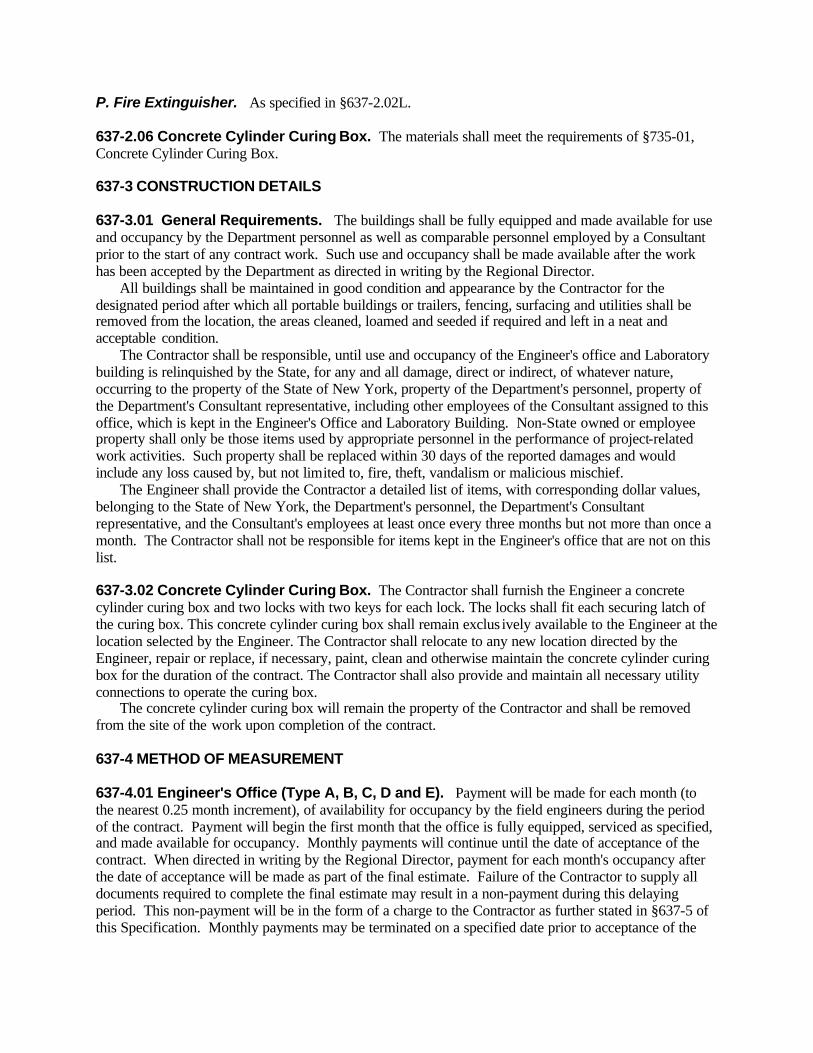
P. Fire Extinguisher. As specified in §637-2.02L. 637-2.06 Concrete Cylinder Curing Box. The materials shall meet the requirements of §735-01, Concrete Cylinder Curing Box. 637-3 CONSTRUCTION DETAILS 637-3.01 General Requirements. The buildings shall be fully equipped and made available for use and occupancy by the Department personnel as well as comparable personnel employed by a Consultant prior to the start of any contract work. Such use and occupancy shall be made available after the work has been accepted by the Department as directed in writing by the Regional Director. All buildings shall be maintained in good condition and appearance by the Contractor for the designated period after which all portable buildings or trailers, fencing, surfacing and utilities shall be removed from the location, the areas cleaned, loamed and seeded if required and left in a neat and acceptable condition. The Contractor shall be responsible, until use and occupancy of the Engineer's office and Laboratory building is relinquished by the State, for any and all damage, direct or indirect, of whatever nature, occurring to the property of the State of New York, property of the Department's personnel, property of the Department's Consultant representative, including other employees of the Consultant assigned to this office, which is kept in the Engineer's Office and Laboratory Building. Non-State owned or employee property shall only be those items used by appropriate personnel in the performance of project-related work activities. Such property shall be replaced within 30 days of the reported damages and would include any loss caused by, but not limited to, fire, theft, vandalism or malicious mischief. The Engineer shall provide the Contractor a detailed list of items, with corresponding dollar values, belonging to the State of New York, the Department's personnel, the Department's Consultant representative, and the Consultant's employees at least once every three months but not more than once a month. The Contractor shall not be responsible for items kept in the Engineer's office that are not on this list. 637-3.02 Concrete Cylinder Curing Box. The Contractor shall furnish the Engineer a concrete cylinder curing box and two locks with two keys for each lock. The locks shall fit each securing latch of the curing box. This concrete cylinder curing box shall remain exclus ively available to the Engineer at the location selected by the Engineer. The Contractor shall relocate to any new location directed by the Engineer, repair or replace, if necessary, paint, clean and otherwise maintain the concrete cylinder curing box for the duration of the contract. The Contractor shall also provide and maintain all necessary utility connections to operate the curing box. The concrete cylinder curing box will remain the property of the Contractor and shall be removed from the site of the work upon completion of the contract. 637-4 METHOD OF MEASUREMENT 637-4.01 Engineer's Office (Type A, B, C, D and E). Payment will be made for each month (to the nearest 0.25 month increment), of availability for occupancy by the field engineers during the period of the contract. Payment will begin the first month that the office is fully equipped, serviced as specified, and made available for occupancy. Monthly payments will continue until the date of acceptance of the contract. When directed in writing by the Regional Director, payment for each month's occupancy after the date of acceptance will be made as part of the final estimate. Failure of the Contractor to supply all documents required to complete the final estimate may result in a non-payment during this delaying period. This non-payment will be in the form of a charge to the Contractor as further stated in §637-5 of this Specification. Monthly payments may be terminated on a specified date prior to acceptance of the

contract by written notification by the Regional Director that such office will no longer be required on the contract. No payment will be made for occupancy and services during the periods of contract extension of time where Engineering Charges are assessed, except that, in such cases, payment for each month's occupancy after the date of acceptance will be made as part of the final estimate when directed in writing by the Regional Director. 637-4.02 Laboratory. Payment will be made for each building or trailer furnished under this work as follows: Seventy-five (75%) of the amount bid will be paid when the building or trailer equipped as specified has been placed on the work site and fully operative. The remaining twenty-five percent (25%) will be paid when the Engineer estimates the contract to be ninety percent (90%) complete, on a dollar basis. 637-4.03 Concrete Cylinder Curing Box. Concrete cylinder curing boxes will be measured by the number of units furnished and installed and actually used in accordance with these specifications. 637-5 BASIS OF PAYMENT 637-5.01 Engineer's Office (Type A, B, C, D, and E). The unit price bid per month shall include the cost of all labor, material, equipment, ground rental and utility charges necessary to complete the work. No payment will be made under Engineer's Office for each calendar day during which there are deficiencies in compliance with the requirements of any sub-section of this specification. The first calendar day shall commence 24 hours after notice to the Contractor of such a deficiency. This non-payment shall be deducted from the Contractor's next estimate as a charge to Contractor on the item. The amount of such calendar day non-payment will be determined by dividing the unit price bid per month by 30. In addition, if the cited deficiencies exceeds 72 hours or is permitted to recur, liquidated damages will be assessed at twenty percent (20%) the rate shown in Table 108-1 of §108-03 for each subsequent calendar day or part thereof that a cited deficiency resulting in non-payment, as prescribed herein, is not corrected. 637-5.02 Laboratory. The price bid for each building or trailer shall include the cost of furnishing all labor, materials and equipment necessary to erect, relocate and remove the building or traile r as directed by the Engineer, together with all fuel, water, ground rental, or other expenses incidental thereto. 637-5.03 Concrete Cylinder Curing Box. The unit price bid for each box shall include the cost of all labor, material, equipment, ground rental, relocation, repair or replacement, painting, cleaning, maintenance, and utility charges necessary for operation. Payment will be made under: Item No. Item Pay Unit 637.01 M Laboratory Building Each 637.03 M Concrete Cylinder Curing Box Each 637.0502 M Engineer's Office-Type A Month 637.0602 M Engineer's Office-Type B Month 637.0702 M Engineer's Office-Type C Month 637.0802 M Engineer's Office-Type D Month 637.0902 M Engineer's Office--Type E Month SECTION 638 - WHITE SYNTHETIC RESIN BINDER CONCRETE
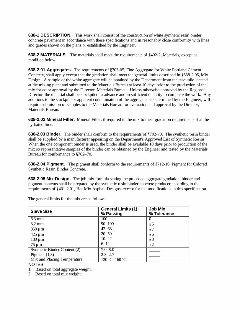
638-1 DESCRIPTION. This work shall consist of the construction of white synthetic resin binder concrete pavement in accordance with these specifications and in reasonably close conformity with lines and grades shown on the plans or established by the Engineer. 638-2 MATERIALS. The materials shall meet the requirements of §402-2, Materials, except as modified below. 638-2.01 Aggregates. The requirements of §703-05, Fine Aggregate for White Portland Cement Concrete, shall apply except that the gradation shall meet the general limits described in §638-2.05, Mix Design. A sample of the white aggregate will be obtained by the Department from the stockpile located at the mixing plant and submitted to the Materials Bureau at least 10 days prior to the production of the mix for color approval by the Director, Materials Bureau. Unless otherwise approved by the Regional Director, the material shall be stockpiled in advance and in sufficient quantity to complete the work. Any additions to the stockpile or apparent contamination of the aggregate, as determined by the Engineer, will require submission of samples to the Materials Bureau for evaluation and approval by the Director, Materials Bureau. 638-2.02 Mineral Filler. Mineral Filler, if required in the mix to meet gradation requirements shall be hydrated lime. 638-2.03 Binder. The binder shall conform to the requirements of §702-70. The synthetic resin binder shall be supplied by a manufacturer appearing on the Department's Approved List of Synthetic Resins. When the one component binder is used, the binder shall be available 10 days prior to production of the mix so representative samples of the binder can be obtained by the Engineer and tested by the Materials Bureau for conformance to §702–70. 638-2.04 Pigment. The pigment shall conform to the requirements of §712-16, Pigment for Colored Synthetic Resin Binder Concrete. 638-2.05 Mix Design. The job mix formula stating the proposed aggregate gradation, binder and pigment contents shall be prepared by the synthetic resin binder concrete producer according to the requirements of §401-2.01, Hot Mix Asphalt Designs, except for the modifications in this specification. The general limits for the mix are as follows:
Sieve Size General Limits (1) % Passing
Job Mix % Tolerance
6.3 mm 3.2 mm 850 :m 425 :m 180 :m 75 :m
100 90–100 42–68 20–50 10–22 6–12
0 "5 "7 "6 "3 "2
Synthetic Binder Content (2) Pigment (1,3) Mix and Placing Temperature
7.0–8.0 2.3–2.7 120EC–160EC
_____ _____ _____
NOTES: 1. Based on total aggregate weight. 2. Based on total mix weight.

3. The pigment shall be considered as mineral filler passing the 75 :m sieve. 638-2.06 Tack Coat. The tack coat shall be supplied by a manufacturer appearing on the Department's Approved List of Synthetic Resins. The tack coat shall conform to the requirements of §702–71. The tack coat material shall be available 10 days prior to production of the mix so representative samples of the tack coat can be obtained by the Engineer and tested by the Materials Bureau for conformance of §702–71. 638-3 CONSTRUCTION DETAILS. Except as provided in this specification, the construction requirements shall meet those of §402-3, Hot Mix Asphalt (HMA) Pavements - Construction Details. 638-3.01 Weather Limitations. The requirements for top course mixes in §402-3.01, Weather and Seasonal Limitations, shall apply. 638-3.02 Preparation of Mixture. The mixing plant shall meet the requirements of §401-3.08 unless otherwise approved by the Director, Materials Bureau. Before the pugmill is allowed to produce white synthetic resin binder concrete, it shall be thoroughly cleaned by charging a minimum of two (2) successive batches of hot dry aggregate into the pugmill and mixing each batch for a minimum of four (4) minutes. In addition, the first batch of white synthetic resin binder concrete produced, after a change from normal asphalt concrete production, shall not be incorporated into the work. Such batches shall be at least fifty (50) percent of the rated pugmill capacity. This batch may also be used for the first material passed through the paver as described in §638–3.04, Paving. The white aggregate shall be introduced into the pugmill, between the limits of 120EC to 180EC and the temperature of the synthetic resin binder (one component) shall be maintained between the limits of 130EC and 150EC. When the binder is added directly into the pugmill in cold, prepackaged units (two components), the temperature of the aggregate may be increased accordingly to meet the specified mix temperature, but shall not exceed 220EC. For either method of binder addition, the resulting mix temperature shall be in the range of 120EC to 160EC. The pigment, resin chips, plasticizing oil and hydrated lime shall be added to the pugmill in whole bag units. If the pigment and/or hydrated lime is not delivered from the manufacturers as whole units, the Contractor may weigh and repackage in a manner approved by the Engineer so that the pigment and/or hydrated lime may be added as whole units. The hydrated lime may be added in a manner approved by the Engineer, if difficulties are encountered in maintaining the specified mix temperature when adding the hydrated lime directly to the pugmill. Batching and mixing requirements for the White Synthetic Resin Binder Concrete are as follows: A. One Component Binder. After the hot aggregate is discharged into the pugmill, add the pigment and hydrated lime in whole bag units as required and dry mix for a minimum of 15 seconds. After the dry mix the synthetic resin binder should be added and wet mixed for a minimum of 45 seconds. B. Two Component Binder. After the hot aggregate is discharged into the pugmill add resin chips in whole bag units as required. This should be immediately followed by the addition of the hydrated lime in whole bag units and dry mixed for 30 seconds. Following the dry mix add the plasticizing oil and pigment in whole bag units in that order and wet mix for 30 seconds after all components are in the pugmill. Any increase in pigment content above that specified on the job mix formula for the convenience of mixing shall be made at no additional cost to the Department. The pigment content may be increased within the general limits, as directed by the Engineer, to obtain a satisfactory color during production. 638-3.03 Preparation of Surface. All surfaces to be paved shall be thoroughly cleaned of all foreign material, including membrane curing compound of Portland Cement concrete pavement, prior to the placing of the pavement. A tack coat, consisting of a uniform application of rapid curing synthetic resin liquid, §702–71, shall be applied at a uniform rate between 0.15 to 0.25 liters per square meter over the

areas to be paved. The tack coat shall be applied with either a paint roller or spray unit to assure uniform application. The tack coat shall not be poured onto the pavement surface for application. After the tack coat application, curing time shall be sufficient to permit the coating to become tacky before paving. No traffic shall be permitted on the tack coated surface. 638-3.04 Paving. The mix shall be laid between the temperatures of 120E to 160EC as specified by the Engineer. All areas of uniform width of 1.2 meters or more shall be paved with an approved paving machine. Areas of narrow or variable width may be placed without a paver but in a manner approved by the Engineer. All paving edges shall be formed in a manner approved by the Engineer to obtain a true edge. The equipment including trucks, paving machine rollers and tools which come in contact with the white synthetic resin binder concrete shall be thoroughly cleaned before use. In addition, the paving machine shall be cleaned of excess asphalt by spraying with solvent. This shall be directly followed by the passage and subsequent wastage of at least one (1) metric ton of the white material. The material may be from the same batch used to clean the pugmill. 638-3.05 Compaction. Provisions of §402-3.07 Compaction shall apply except that a minimum of two passes of a nominal 9 metric ton steel wheel tandem roller shall be used for compaction. The edge forms shall be removed prior to applying the second roller pass. This shall be done as expeditiously as possible so that the second roller pass is completed while the mat is still hot. Forms used for the formation of transverse drainage troughs shall be kept in place until the completion of all rolling operations. Narrow areas which are subject to overstressing with a 9 metric ton roller may be rolled with a small roller as approved by the Engineer. The paving edge forms shall be removed prior to applying the final roller pass with the small roller as previously described for the 9 metric ton rollers. The use of a pneumatic tire roller will not be required for this item. 638-4 METHOD OF MEASUREMENT. The quantity of white synthetic resin binder concrete shall be measured by the number of metric tons of compacted material in place. 638-5 BASIS OF PAYMENT. The unit price bid per metric ton of white synthetic resin binder concrete shall include the cost of all materials, equipment and labor necessary to complete the work including the synthetic resin binder, pigment and tack coat. Payment will be made under: Item No. Item Pay Unit 638.0104 M White Synthetic Resin Binder Concrete Metric Ton SECTION 639 (VACANT) SECTION 640 - REFLECTORIZED PAVEMENT MARKING PAINTS 640-1 DESCRIPTION. Under this work, the Contractor shall furnish and apply painted reflectorized pavement marking paint at the locations and in accordance with the patterns indicated on the plans or as directed by the Engineer, and in accordance with the NYSMUTCD and these specifications. 640-2 MATERIALS. Reflectorized pavement marking paints shall be selected from the Department’s Approved List of White and Yellow Reflectorized Pavement Marking Paints. Project acceptance will be based on the appearance of an approved brand name on the container label. All paints shall conform to Federal, State, and local air pollution regula tions, including those for the control (emission) of volatile organic compounds (VOC) as established by the U.S. Environmental Protection Agency, and the New York State Department of Environmental Conservation.
Reflective glass beads shall conform to §727-05 Glass Beads for Reflectorized Pavement Marking Paints. Details for obtaining Approved List status are available from the Materials Bureau. 640-3 CONSTRUCTION DETAILS 640-3.01 General. All pavement markings and patterns shall be placed as shown in the contract documents and in accordance with the New York State Manual of Uniform Traffic Control Devices. Before any pavement marking work is begun a schedule of operations shall be submitted to and approved by the Engineer. When pavement markings are applied under traffic, the Contractor shall provide all the necessary flags, signs, cones, shadow vehicles, flashing arrow boards, etc. to maintain and protect traffic, to protect the work operation, and to protect the painted pavement markings until thoroughly dry and serviceable. No additional payment will be made for these items. The application of pavement markings shall be done in the general direction of traffic. Striping against the direction of normal flow of traffic shall not be allowed. The Contractor shall be responsible for cleaning the pavement, to the satisfaction of the Engineer, of dust, dirt, and other foreign material which may be detrimental to the adhesion of the paint film. When necessary, the Contractor shall establish marking line points at nine (9) meter intervals throughout the length of the pavement or as directed by the Engineer. The Contractor shall be responsible for removing, to the satisfaction of the Engineer, all tracking marks, spilled paint, and paint applied in unauthorized areas. 640-3.02 Application of Pavement Markings. Painted pavement markings shall be applied with either atomizing or airless type striping equipment. The striping equipment may be either truck mounted or hand operated, and shall be equipped with glass bead dispensing equipment. The striping equipment shall be compatible with and suitable for the application of the type of paint being used. At the time of paint application, the pavement surface and ambient temperature shall not be less than 10EC, the relative humidity shall not exceed 85%, and the pavement surface shall be dry. Painted pavement markings shall not be applied during periods of rain or if rain is imminent. Waterborne type paints shall not be applied if rain is expected within 4 hours after the paint application. Paint shall be applied in strict accordance with the manufacturer’s recommendations for use. In no case shall the paint be heated above 65EC. The painted pavement markings shall be uniformly applied to the pavement surface at the minimum specified wet film thickness. Immediately following paint application reflective glass beads shall be uniformly applied to the wet paint film at the rate of 0.75 kg/L of paint. The applied pavement markings shall have clean-cut edges, and true and smooth alignment. On pavements where traffic is to be maintained and the final marking pattern is known, reflectorized pavement marking paint shall be applied before nightfall or before the end of the working day, whichever comes sooner. If the Contractor is unable to apply these final pavement markings, where traffic is to be maintained, then Short-Term Pavement Markings meeting the requirements of §619-3.06 shall be installed using removable reflectorized pavement markings, offset from the location of the project’s final pavement markings, at no additional cost to the State. 640-4 METHOD OF MEASUREMENT. Pavement striping will be measured in linear meters along the centerline of the pavement stripe and shall be based on a 100 mm wide stripe. Measurement for striping with a plan width greater or less than the basic 100 mm as shown in the contract documents or as directed by the Engineer, will be made by the following method: Plan Width of Striping (Millimeters) x Meters 100 Millimeters
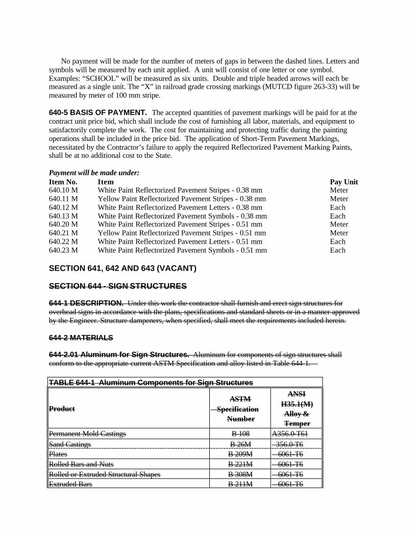
No payment will be made for the number of meters of gaps in between the dashed lines. Letters and symbols will be measured by each unit applied. A unit will consist of one letter or one symbol. Examples: “SCHOOL” will be measured as six units. Double and triple headed arrows will each be measured as a single unit. The “X” in railroad grade crossing markings (MUTCD figure 263-33) will be measured by meter of 100 mm stripe. 640-5 BASIS OF PAYMENT. The accepted quantities of pavement markings will be paid for at the contract unit price bid, which shall include the cost of furnishing all labor, materials, and equipment to satisfactorily complete the work. The cost for maintaining and protecting traffic during the painting operations shall be included in the price bid. The application of Short-Term Pavement Markings, necessitated by the Contractor’s failure to apply the required Reflectorized Pavement Marking Paints, shall be at no additional cost to the State. Payment will be made under: Item No. Item Pay Unit 640.10 M White Paint Reflectorized Pavement Stripes - 0.38 mm Meter 640.11 M Yellow Paint Reflectorized Pavement Stripes - 0.38 mm Meter 640.12 M White Paint Reflectorized Pavement Letters - 0.38 mm Each 640.13 M White Paint Reflectorized Pavement Symbols - 0.38 mm Each 640.20 M White Paint Reflectorized Pavement Stripes - 0.51 mm Meter 640.21 M Yellow Paint Reflectorized Pavement Stripes - 0.51 mm Meter 640.22 M White Paint Reflectorized Pavement Letters - 0.51 mm Each 640.23 M White Paint Reflectorized Pavement Symbols - 0.51 mm Each SECTION 641, 642 AND 643 (VACANT) SECTION 644 - SIGN STRUCTURES 644-1 DESCRIPTION. Under this work the contractor shall furnish and erect sign structures for overhead signs in accordance with the plans, specifications and standard sheets or in a manner approved by the Engineer. Structure dampeners, when specified, shall meet the requirements included herein. 644-2 MATERIALS 644-2.01 Aluminum for Sign Structures. Aluminum for components of sign structures shall conform to the appropriate current ASTM Specification and alloy listed in Table 644-1. TABLE 644-1 Aluminum Components for Sign Structures
Product ASTM
Specification Number
ANSI H35.1(M) Alloy & Temper
Permanent Mold Castings B 108 A356.0-T61 Sand Castings B 26M 356.0-T6 Plates B 209M 6061-T6 Rolled Bars and Nuts B 221M 6061-T6 Rolled or Extruded Structural Shapes B 308M 6061-T6 Extruded Bars B 211M 6061-T6
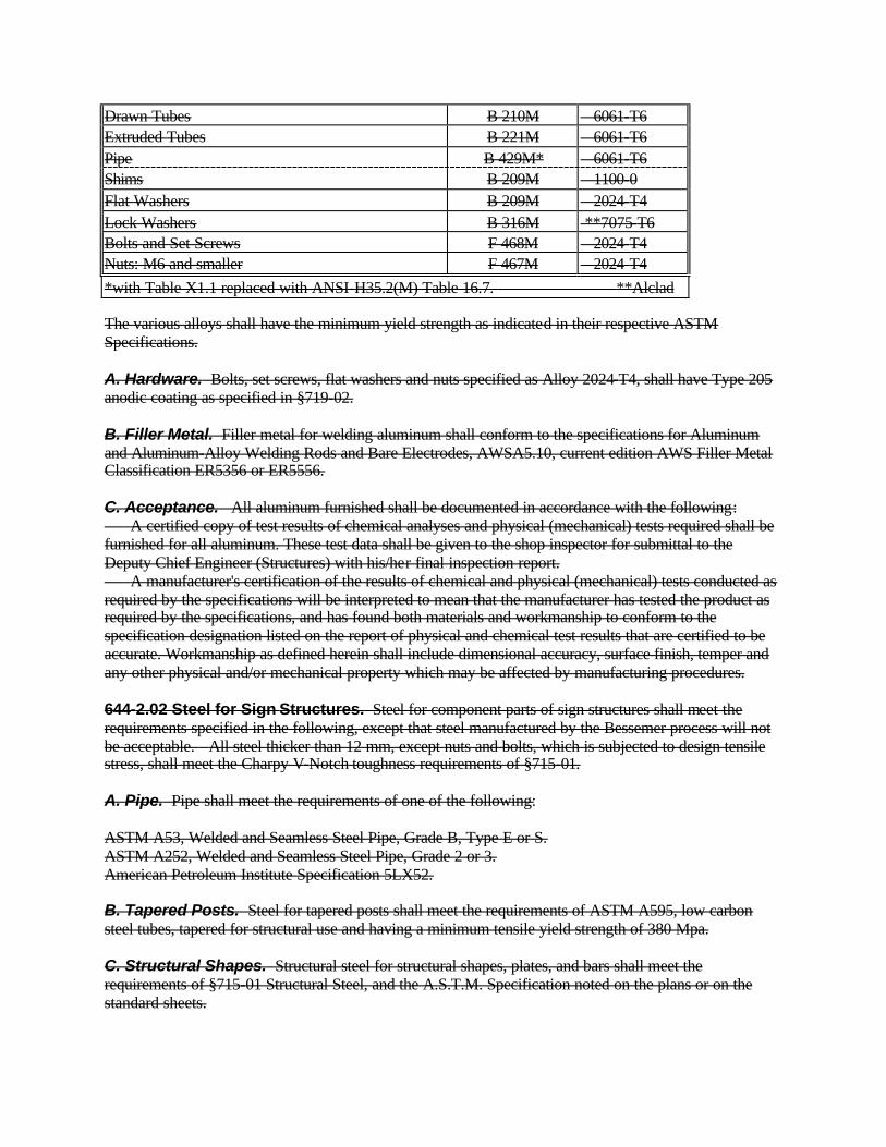
Drawn Tubes B 210M 6061-T6 Extruded Tubes B 221M 6061-T6 Pipe B 429M* 6061-T6 Shims B 209M 1100-0 Flat Washers B 209M 2024-T4 Lock Washers B 316M **7075-T6 Bolts and Set Screws F 468M 2024-T4 Nuts: M6 and smaller F 467M 2024-T4 *with Table X1.1 replaced with ANSI-H35.2(M) Table 16.7. **Alclad The various alloys shall have the minimum yield strength as indicated in their respective ASTM Specifications. A. Hardware. Bolts, set screws, flat washers and nuts specified as Alloy 2024-T4, shall have Type 205 anodic coating as specified in §719-02. B. Filler Metal. Filler metal for welding aluminum shall conform to the specifications for Aluminum and Aluminum-Alloy Welding Rods and Bare Electrodes, AWSA5.10, current edition AWS Filler Metal Classification ER5356 or ER5556. C. Acceptance. All aluminum furnished shall be documented in accordance with the following: A certified copy of test results of chemical analyses and physical (mechanical) tests required shall be furnished for all aluminum. These test data shall be given to the shop inspector for submittal to the Deputy Chief Engineer (Structures) with his/her final inspection report. A manufacturer's certification of the results of chemical and physical (mechanical) tests conducted as required by the specifications will be interpreted to mean that the manufacturer has tested the product as required by the specifications, and has found both materials and workmanship to conform to the specification designation listed on the report of physical and chemical test results that are certified to be accurate. Workmanship as defined herein shall include dimensional accuracy, surface finish, temper and any other physical and/or mechanical property which may be affected by manufacturing procedures. 644-2.02 Steel for Sign Structures. Steel for component parts of sign structures shall meet the requirements specified in the following, except that steel manufactured by the Bessemer process will not be acceptable. All steel thicker than 12 mm, except nuts and bolts, which is subjected to design tensile stress, shall meet the Charpy V-Notch toughness requirements of §715-01. A. Pipe. Pipe shall meet the requirements of one of the following: ASTM A53, Welded and Seamless Steel Pipe, Grade B, Type E or S. ASTM A252, Welded and Seamless Steel Pipe, Grade 2 or 3. American Petroleum Institute Specification 5LX52. B. Tapered Posts. Steel for tapered posts shall meet the requirements of ASTM A595, low carbon steel tubes, tapered for structural use and having a minimum tensile yield strength of 380 Mpa. C. Structural Shapes. Structural steel for structural shapes, plates, and bars shall meet the requirements of §715-01 Structural Steel, and the A.S.T.M. Specification noted on the plans or on the standard sheets.

D. Anchor Bolts, Nuts and Washers. Anchor bolts, nuts and washers shall meet the requirements of Materials Detail 723-60, or the following: Anchor Bolts: ASTM F 568 Class 4.6 Nuts: ASTM A 563M Carbon and Alloy Steel Nuts, Grade A, Heavy Hex Style Washers: ASTM F 436M Hardened Steel Washers or ASTM F 844 with a hardness of Rockwell C31 - C38 or Brinell 295 - 352. Nuts, washers, and the top third of anchor bolts shall be galvanized in accordance with the requirements of Materials Detail 719-01 Type II, Galvanized Coatings and Repair Methods - Zinc Coating (Hot Dip) on Iron and Steel Hardware. E. High Strength Steel Bolts, Nuts and Washers. High strength connection hardware shall meet the following requirements: Part ASTM Specification Title Bolts A 325M High-Strength Bolts for Structural Steel Joints [Metric] Washers F 436M Hardened Steel Washers [Metric] Nuts A 563M Carbon and Alloy Steel Nuts [Metric] High strength bolts, nuts and washers shall be galvanized in accordance with the requirements of Type II of §719-01, Galvanized Coatings and Repair Methods. F. Acceptance. All steel furnished shall be documented in accordance with the requirements of §715-01 Basis of Acceptance. 644-2.03 Concrete. All cast-in-place pullboxes and sign post foundations shall meet the requirements of Class A concrete in section 501, Portland Cement Concrete General, except that the requirements for inspection facilities, automated batching controls and recordation do not apply. The batching, mixing and curing methods and the inspection facilities shall meet the approval of the Department or its representative. The Contractor may submit, for approval by Director, Materials Bureau, a mix at least equivalent to the specified Class A Concrete. All precast concrete pullboxes and sign post foundations shall meet the requirements of §723-45 Precast Reinforced Concrete Pullboxes. 644-2.04 Sign Structure Dampener. Unless otherwise approved by the D.C.E.S. all sign structure dampeners shall be the Stockbridge type. All dampeners shall meet the manufacturer's specifications. All steel and cast iron components shall be galvanized after fabrication. All material needed for making an attachment(s) to the overhead sign structure shall meet the requirements of that specific structure and the appropriate Standard Sheet. All sign structure dampeners shall meet the following criteria for weight: SPAN LENGTH DAMPENER MASS (kg) Minimum Maximum 43 meters or less 14 18.1 Greater than 43 meters 16 18.1 644-2.05 Sign Structure Bearing Pads. Pads shall conform to the material requirements of the following: Type A. Pad-Rubber Impregnated Woven Cotton Fabric 728-01 Type B. Pad-Rubber Impregnated Random Fiber Pad 728-02
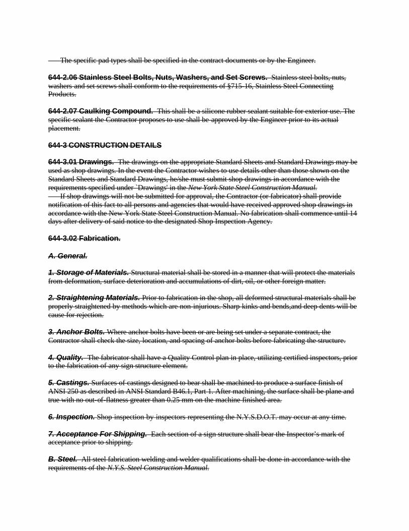
The specific pad types shall be specified in the contract documents or by the Engineer. 644-2.06 Stainless Steel Bolts, Nuts, Washers, and Set Screws. Stainless steel bolts, nuts, washers and set screws shall conform to the requirements of §715-16, Stainless Steel Connecting Products. 644-2.07 Caulking Compound. This shall be a silicone rubber sealant suitable for exterior use. The specific sealant the Contractor proposes to use shall be approved by the Engineer prior to its actual placement. 644-3 CONSTRUCTION DETAILS 644-3.01 Drawings. The drawings on the appropriate Standard Sheets and Standard Drawings may be used as shop drawings. In the event the Contractor wishes to use details other than those shown on the Standard Sheets and Standard Drawings, he/she must submit shop drawings in accordance with the requirements specified under `Drawings' in the New York State Steel Construction Manual. If shop drawings will not be submitted for approval, the Contractor (or fabricator) shall provide notification of this fact to all persons and agencies that would have received approved shop drawings in accordance with the New York State Steel Construction Manual. No fabrication shall commence until 14 days after delivery of said notice to the designated Shop Inspection Agency. 644-3.02 Fabrication. A. General. 1. Storage of Materials. Structural material shall be stored in a manner that will protect the materials from deformation, surface deterioration and accumulations of dirt, oil, or other foreign matter. 2. Straightening Materials. Prior to fabrication in the shop, all deformed structural materials shall be properly straightened by methods which are non-injurious. Sharp kinks and bends,and deep dents will be cause for rejection. 3. Anchor Bolts. Where anchor bolts have been or are being set under a separate contract, the Contractor shall check the size, location, and spacing of anchor bolts before fabricating the structure. 4. Quality. The fabricator shall have a Quality Control plan in place, utilizing certified inspectors, prior to the fabrication of any sign structure element. 5. Castings. Surfaces of castings designed to bear shall be machined to produce a surface finish of ANSI 250 as described in ANSI Standard B46.1, Part 1. After machining, the surface shall be plane and true with no out-of-flatness greater than 0.25 mm on the machine finished area. 6. Inspection. Shop inspection by inspectors representing the N.Y.S.D.O.T. may occur at any time. 7. Acceptance For Shipping. Each section of a sign structure shall bear the Inspector’s mark of acceptance prior to shipping. B. Steel. All steel fabrication welding and welder qualifications shall be done in accordance with the requirements of the N.Y.S. Steel Construction Manual.
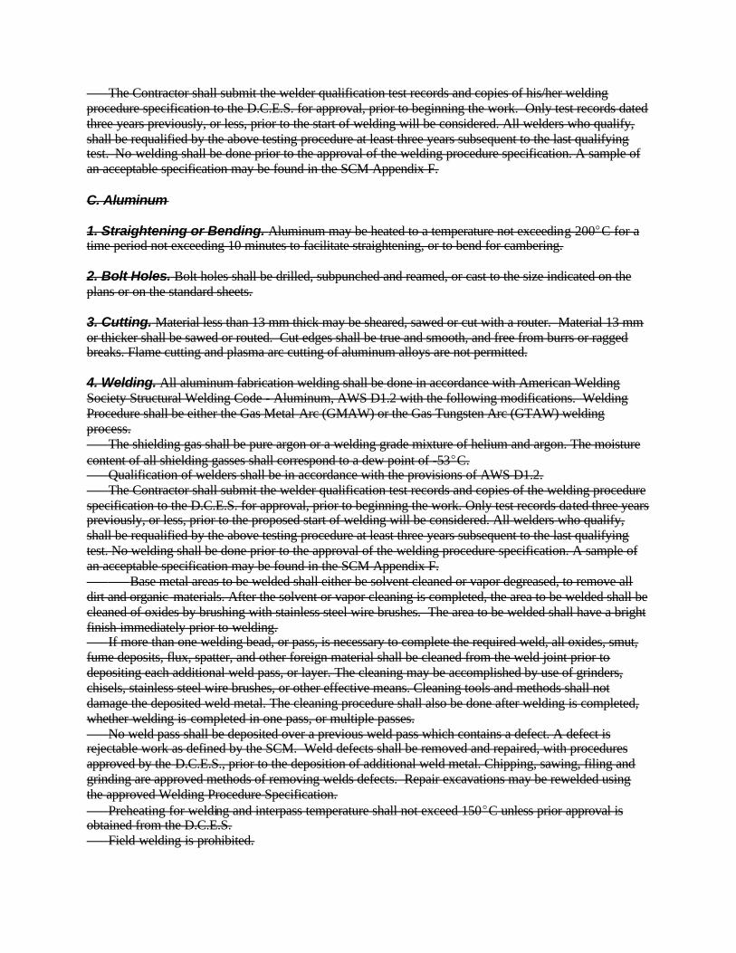
The Contractor shall submit the welder qualification test records and copies of his/her welding procedure specification to the D.C.E.S. for approval, prior to beginning the work. Only test records dated three years previously, or less, prior to the start of welding will be considered. All welders who qualify, shall be requalified by the above testing procedure at least three years subsequent to the last qualifying test. No welding shall be done prior to the approval of the welding procedure specification. A sample of an acceptable specification may be found in the SCM Appendix F. C. Aluminum 1. Straightening or Bending. Aluminum may be heated to a temperature not exceeding 200EC for a time period not exceeding 10 minutes to facilitate straightening, or to bend for cambering. 2. Bolt Holes. Bolt holes shall be drilled, subpunched and reamed, or cast to the size indicated on the plans or on the standard sheets. 3. Cutting. Material less than 13 mm thick may be sheared, sawed or cut with a router. Material 13 mm or thicker shall be sawed or routed. Cut edges shall be true and smooth, and free from burrs or ragged breaks. Flame cutting and plasma arc cutting of aluminum alloys are not permitted. 4. Welding. All aluminum fabrication welding shall be done in accordance with American Welding Society Structural Welding Code - Aluminum, AWS D1.2 with the following modifications. Welding Procedure shall be either the Gas Metal Arc (GMAW) or the Gas Tungsten Arc (GTAW) welding process. The shielding gas shall be pure argon or a welding grade mixture of helium and argon. The moisture content of all shielding gasses shall correspond to a dew point of -53EC. Qualification of welders shall be in accordance with the provisions of AWS D1.2. The Contractor shall submit the welder qualification test records and copies of the welding procedure specification to the D.C.E.S. for approval, prior to beginning the work. Only test records dated three years previously, or less, prior to the proposed start of welding will be considered. All welders who qualify, shall be requalified by the above testing procedure at least three years subsequent to the last qualifying test. No welding shall be done prior to the approval of the welding procedure specification. A sample of an acceptable specification may be found in the SCM Appendix F. Base metal areas to be welded shall either be solvent cleaned or vapor degreased, to remove all dirt and organic materials. After the solvent or vapor cleaning is completed, the area to be welded shall be cleaned of oxides by brushing with stainless steel wire brushes. The area to be welded shall have a bright finish immediately prior to welding. If more than one welding bead, or pass, is necessary to complete the required weld, all oxides, smut, fume deposits, flux, spatter, and other foreign material shall be cleaned from the weld joint prior to depositing each additional weld pass, or layer. The cleaning may be accomplished by use of grinders, chisels, stainless steel wire brushes, or other effective means. Cleaning tools and methods shall not damage the deposited weld metal. The cleaning procedure shall also be done after welding is completed, whether welding is completed in one pass, or multiple passes. No weld pass shall be deposited over a previous weld pass which contains a defect. A defect is rejectable work as defined by the SCM. Weld defects shall be removed and repaired, with procedures approved by the D.C.E.S., prior to the deposition of additional weld metal. Chipping, sawing, filing and grinding are approved methods of removing welds defects. Repair excavations may be rewelded using the approved Welding Procedure Specification. Preheating for welding and interpass temperature shall not exceed 150EC unless prior approval is obtained from the D.C.E.S. Field welding is prohibited.

644-3.03 Transportation. Sign structures (including supports) shall be supported for their full length during shipment. Structures shall be shimmed, braced, blocked, and tied down to prevent distortion, or other damage from occurring during transportation. The use of any device which does not support the member for its entire length will not be permitted. This prohibition includes but is not limited to dolly wheels and trailers. The Engineer shall examine sign structures after delivery to the work site. Selected welds may be trepanned to verify the required effective weld throat. Defects in materials or workmanship will be cause for rejection of the overhead sign structures or their supports. Defective structures, or components, shall be removed from the work site and repaired, or replaced as required by the D.C.E.S. All work relating to the repair, or replacement, of defective structures, or components, shall be done at no additional cost to the State. 644-3.04 Excavation. All excavation shall conform to Section 206 Trench, Culvert and Structure Excavation except that slope layback shall not be allowed for bored foundations. Included shall be the protection of workers and the public. Details of this protection shall conform to the requirements of 29CFR1926, Safety and Health Regulations for Construction (OSHA) and §107-05 Safety and Health Requirements Paragraph F. Excavation shall not be performed until immediately before installation of the footings, pullboxes or any other appurtenances. The excavated material shall be placed in a location or locations approved by the Engineer. These locations shall be selected by the Contractor so as to cause the least inconvenience to vehicular and pedestrian traffic and to avoid interference with the surface drainage. All surplus excavated material shall be removed and disposed of by the Contractor as specified in §203-3.08 Disposal of Surplus Excavated Materials. Excavation shall be backfilled as specified in §203-3.15, Fill and Backfill at Structures, Culverts, Pipes, Conduits and Direct Burial Cables. The outline of all areas to be removed in sidewalks, driveways, and pavement shall be saw cut to a depth of at least 75 mm prior to removing the sidewalk, driveway or pavement. Cuts shall be neat and true along score lines with no shatter outside the removal area. Damaged saw cut areas shall be recut. Pavement, shoulder, sidewalks, curbs, driveways, lawns, plants and other such features shall be replaced in kind with material of equal quality or as shown on the plans, standard sheets or as directed by the Engineer. For transverse sidewalk, curb or gutter cuts in concrete the entire square or section shall be removed and replaced with the same kind and quality of material. For longitudinal cuts in concrete sidewalks only the area removed between sawcuts shall be replaced unless specified otherwise on the plans. Whenever a part of a square or slab of existing concrete sidewalk, curb, gutter or driveway is broken or damaged, the entire square, section or slab shall be removed and replaced with the same kind and quality of material. 644-3.05 Concrete Foundation. Foundations shall be constructed as shown in the contract documents or as directed by the Engineer. However, the Contractor has the option to use either Cast-in-Place or Precast Concrete foundations for the circular footings. 644-3.06 Erection of Sign Structures A. Handling and Storage. Structural members shall be loaded, moved, and unloaded such that they will not be subjected to stresses in excess of those provided for by the structure design. Permanent distortion, or other damage, attributable to the Contractor's operations will be cause for rejection. Members stored either in the fabricator's storage area, or at the work site, or at other storage areas, shall be supported off the ground in a manner which will not allow distortion, or other damage to occur.
B. Field Inspection. All material shall be field inspected for workmanship and finish. Also, immediately prior to erection, all material shall be inspected by the Engineer. Materials and fabrication which do not conform to contract document requirements, or damage attributable to the Contractor's operations shall be cause for rejection. Dirty components shall be cleaned prior to erection. Rejected structures or components shall not be used in the work but shall be removed from the work site. Damage includes, but is not limited to, bends, kinks, dents, cracks and pits. C. Setting Anchor Bolts. Anchor bolts shall be carefully set to proper location, alignment, and elevation by using templates. Templates cast into the footing concrete shall have minimum 50 mm diameter perforations or be made of bar sock to prevent honeycombing. Templates exposed in the end product shall be galvanized. Elevations shall be determined by the Engineer. Anchor bolts shall not be realigned by bending to fit the base plate. Anchor bolts that do not fit the sign base plates will be rejected. The Contractor may propose a remediation method for rejected anchor bolts subject to approval of the Regional Director. Rejected anchor bolts, and the concrete they are embedded in shall be replaced by new materials at no cost to the Department. D. Bolting. Steel-to-steel flange-bolted connections shall be made with bolts, nuts and washers meeting the material requirements of §715-14 and the galvanizing requirements of §719-01. Each bolt shall be furnished with two flat washers, one to be installed under the bolt head and one under the nut. All connections shall be made by first tightening all nuts and bolts sufficiently to bring all components into full contact with each other. After full contact has been achieved, all connections shall be brought to a condition beyond snug tight as required by Table 1001.3b of the New York State Steel Construction Manual. “Snug tight” is defined by the S.C.M., Part 1001.3. Aluminum-to-steel and aluminum-to-aluminum flange-bolted connections shall be made with bolts and nuts meeting the material requirements of §715-14 and the galvanizing requirements of §719-01, unless other bolts are specified in the Contract Documents. Each bolt shall be furnished with two stainless steel flat washers meeting the requirements of §715-16. One washer shall be installed under the bolt head and one under the nut. The connection shall be made by first tightening all bolts to bring the components into full contact with each other. All high-strength bolts shall then be tightened to the “snug torque” value shown in TABLE 644-2. Tighten other bolts as specified in Contract Documents. Finally, all bolts shall have a second nut installed and sufficiently tightened against the first nut to lock the installation. All aluminum flange-bolted connections shall be sealed against the intrusion of water by means of a silicone rubber sealant placed between the flanges in strict accordance with the sealant manufacturer's instructions. E. Welding. Field welding will not be permitted on any part of the structure. Table 644-2 ALUMINUM FLANGE BOLTING Bolt Size Snug Torque (N?M) Up to and including M16 135 M20 150 M22 and larger 200 F. Galvanized Metal Repair. When directed by the Engineer, the Contractor shall repair damage to the galvanized surfaces in conformance with the field repair requirements specified in §719-01, Galvanized Coatings and Repair Methods. G. Methods and Equipment. Before starting work, the Contractor shall fully inform the Regional Director of the method of erection and types of equipment he proposes to use, which shall be subject to the approval of the Regional Director. This approval shall not be considered as relieving the Contractor of
the responsibility for the safety of the methods or equipment, or for damage to the structures due to overloading. H. Interim Loading. As soon as a span type structure is erected it shall be suitably loaded to prevent excessive resonance of the structure. This interim loading may be either a concentrated dead load or a blank sign panel. The load shall not scratch, mar or otherwise damage the structure. This interim loading shall not be removed until the permanent sign panels are in place. If the plans or standard sheets call for a dampener on the structure, it may be installed in lieu of the interim loading. All materials used in this loading except required dampener, shall remain the property of the Contractor and shall be removed by the Contractor from the site of work. If the sign structure is damaged due to the lack or insufficiency of the interim loading, it shall be repaired or replaced, as directed by the Engineer. Should any cantilever type structure show signs of excessive resonance it shall be similarly loaded. No work shall be done without the approval of the Engineer. 644-3.07 Erection of Dampener. The dampener shall be securely clamped to the overhead sign structure in the position shown on the plans or standard sheets, preferably before the sign structure is erected. 644-4 METHOD OF MEASUREMENT 644-4.01 Sign Structure. The work will be measured as the number of sign structures (including dampener), without sign panels, installed. 644-4.02 Circular Footing Method A. The payment quantity will be the volume shown for the specified footing in the table on the standard sheet, “Footings for Sign Assemblies With Single Posts,” unless the Engineer orders a change in the footing size. No adjustment will be made for the contractor's election to use a square footing or a precast footing. If the Engineer orders a change in the footing size or to use a square footing, the payment quantity will be the length times the cross section area ordered by the Engineer. 644-5 BASIS OF PAYMENT 644-5.01 Sign Structure. The unit price bid for each structure for supporting sign panels shall be compensation in full for fabricating, furnishing and erecting the structure complete as specified including upright support, span and/or cantilever assemblies, diagonal bracing, all necessary hardware, leveling nuts, regular nuts, washers, cotter pins or clevis pins, caulking compounds and all other material, equipment and labor necessary to properly complete the work as shown on the plans, standard sheets and called for in the specifications. Footings and anchor bolts shall be paid for under separate items or will be furnished by others. 644-5.02 Circular Footing Method A. The unit price bid per cubic meter shall include the excavation, any protective system(s) required to ensure the safety of the workers and the public, backfill (select granular backfill or concrete), form work, concrete, bar reinforcement for concrete, excavation and backfilling of test holes, conduit and fittings, restoration of surfaces in kind, disposal of excess excavated material, and sawcutting. Payment will be made under: Item No. Item Pay Unit 644.01nn M Single Cantilever Sign Structure Each 644.02nn M Double Cantilever Sign Structure Each

644.03nn M Single Span Sign Structure Each 644.04nn M Single Span and Cantilever Sign Structure Each 644.05nn M Multi-Span Sign Structure Each 644.10nn Errata 5/8/03 M Circular Footing Method A Cubic Meter 644.11 M Anchor Bolts Kilogram Note: nn denotes serialized pay item. See §101-02 Definitions of Terms under "Specifications" and the Standard Drawings. “SECTION 644 - OVERHEAD SIGN STRUCTURES 644-1 DESCRIPTION 644-1.01 General. Under this work the Contractor shall fabricate, furnish and erect sign structures for overhead signs in accordance with the contract documents. Within seven (7) days of contract award, the Contractor shall notify the Deputy Chief Engineer, Structures (D.C.E.S.) of the name and address of the fabricator of all overhead sign structures, as outlined in §106-01, Source of Supply and Quality Requirements. This notification shall list the shop or shops in which the sign structures will be fabricated. 644-1.02 Definitions. Overhead Sign Structures (OSS) are structures with vertical supports and horizontal arms or chords used to support signs over any portion of the roadway, including the shoulders. Span Wire Assemblies supporting overhead signs, and structures supporting both traffic signal equipment and overhead signs are covered under Section 680, Traffic Signals. Bridge fascia mounted signs, where the signage is intended for the under roadway, are also not covered in this Section. OSS are classified into the following three standard types (See Figure 644-1).
A. Single Arm Cantilever. Single (horizontal) arm supported by a single (vertical) post.
B. Trussed Arm Cantilever. Two trussed arms supported by a single post. (If
the arms are not trussed, the structure shall be classified as Non-Standard).
C. Span. Single span, four-chord (quad-chord) superstructure supported by
trussed end posts. OSS that fall outside these categories are Non-Standard. This includes butterfly structures, multi-span structures, structures that are a combination of span and cantilevers, and all other overhead sign structures not included in §644-1.02. 644-2 MATERIALS

644-2.01 Steel for Sign Structures. Steel for component parts of sign structures shall meet the requirements of the New York State Steel Construction Manual and the following: All material greater than 13 mm thick shall meet the Charpy V-Notch toughness requirements of §715-01, Structural Steel. Chords, cantilevered arms, end posts, base plates, end and face plates for cantilever arm to post connections, and flange splice plates shall be considered main members. Diagonals, struts and gusset or tab plates shall be considered secondary members. Upon receipt at the fabrication plant, all main member material shall be traceable to a mill test report and traceability shall be maintained throughout the duration of the fabrication.
All main member material thickness shall be a minimum of 6 mm.
Single-Arm Cantilever Structure
Single-Arm Butterfly Structure
Trussed-Arm Cantilever Structure
Trussed-Arm Butterfly Structure
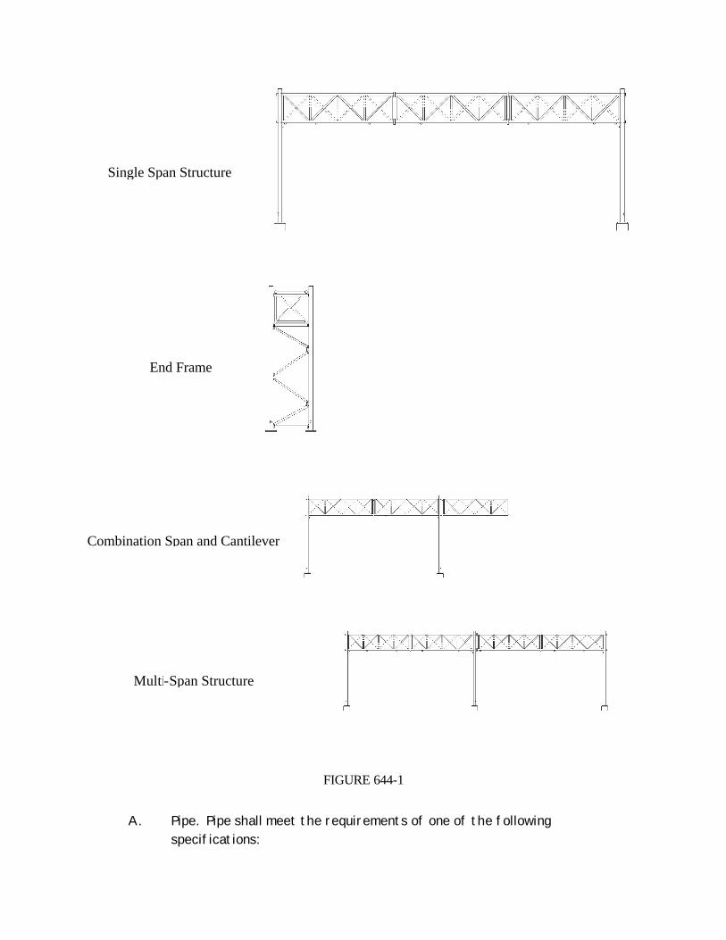
FIGURE 644-1
A. Pipe. Pipe shall meet the requirements of one of the following specifications:
Single Span Structure
End Frame
Combination Span and Cantilever
Multi-Span Structure

ASTM A 53, Welded and Seamless Steel Pipe, Grade B, Type E or S. ASTM A 500, Welded and Seamless Steel Pipe, Grade B (Rounds Only) ASTM A 252, Welded and Seamless Steel Pipe, Grade 2 or 3, provided
that the chemical certifications meet the requirements for ASTM A 53, Grade B, Type E or S.
API 5L American Petroleum Institute Specification 5L, Grade B
In addition to the above material requirements, all pipe used for welded applications shall have a maximum Carbon Equivalency (CE) of 0.40 using the following equation:
CE = %C + %Mn/6 + %Cu/40 + %Ni/20 + %Cr/10 - %Mo/50 - %V/10
B. Structural Steel. Structural steel for structural shapes, plates, and bars shall meet the requirements of §715-01, Structural Steel, and the ASTM Specification noted on the contract documents. Cutting and drilling shall be done in such a manner that the resulting surfaces are free from any gouges or burrs.
C. Anchor Bolts, Nuts and Washers. Anchor bolts, nuts and washers shall meet the requirements of the following:
ASTM F 1554, Grade 55 with Supplementary Requirement S4, Charpy Impact Requirement
Anchor bolts, nuts, and washers shall be galvanized in accordance with the requirements of Materials Detail 719-01 Type II, Galvanized Coatings and Repair Methods - Zinc Coating (Hot Dip) on Iron and Steel Hardware. Anchor bolts shall be the Unified Course Thread Series with Class 2A threads, and shall be galvanized full length. Nuts shall be Grade A, Heavy Hex.
D. High Strength Steel Bolts, Nuts and Washers. Bolted steel connections shall be made with bolts, nuts and washers meeting the material requirements of §715-14, High Strength Bolts, Nuts and Washers, and the galvanizing requirements of §719-01, Galvanized Coatings and Repair Methods. Additionally, the Contractor shall provide documentation that the zinc coated fastener assemblies have satisfied the requirements of ASTM A 325M Section 6.2, R.C. testing. Fasteners in main members shall be sampled and tested in accordance with Section 1001.5 of the New York State Steel Construction Manual, with the exception that the waiver for lot sizes less than 20 bolts shall not apply.
E. U-Bolts. U-Bolts shall conform to material specification ASTM F 1554, Grade 36,and shall be galvanized in accordance with the requirements of Type II of §719-01, Galvanized Coatings and Repair Methods.
F. Galvanizing. All steel shall be galvanized in accordance with §719-01 Type I, except as noted above in §644-2.01 C, D & E. Galvanizing shall provide a minimum coating of 127 ? m. All welding, cutting and drilling shall be done prior to galvanization, and all bolting shall be done after galvanization, except as approved by the Engineer.
G. Acceptance. All steel furnished shall be documented in accordance with the requirements of §715-01 Basis of Acceptance.
644-2.02 Concrete. All overhead sign structure foundations shall meet the requirements of Class A concrete in Section 501, Portland Cement Concrete - General. The Contractor may submit, for approval by Director, Materials Bureau, a mix at least equivalent to the specified Class A Concrete. All precast concrete overhead sign structure foundations shall meet the requirements of §704-03, Precast Concrete - General. 644-3 CONSTRUCTION DETAILS 644-3.01 Drawings. Shop drawings shall be required for all OSS in the contract documents. The Contractor must submit shop drawings in accordance with the requirements of Section 2 in the New York State Steel Construction Manual. 644-3.02 Fabrication. All fabrication, inspection, transportation and erection shall be performed in accordance with the requirements of the New York State Steel Construction Manual.
A. Storage of Materials. Structural material shall be stored in a manner that will protect the materials from deformation, surface deterioration and accumulations of dirt, oil, or other foreign matter.
B. Straightening Materials. Prior to fabrication in the shop, all deformed structural materials shall be properly straightened by methods which are non-injurious. Sharp kinks and bends, and deep dents shall be cause for rejection.
C. Anchor Bolts. Where anchor bolts have been or are being set under a separate contract, the Contractor shall check the size, location, and spacing of anchor bolts before fabricating the structure.
D. Pole Markings. A Sign Structure Identification Number (SIN) shall be attached to the post using white numbers on a green background. The background shall be Green, Class A, Engineer Grade reflective sheeting as described in §730-05, Reflective Sheeting, and shall be 300 mm wide by 150 mm high, with the corners cut to a 40 mm radius. The numbers shall be

cut out from White, Class A, Engineer Grade reflective sheeting and shall be 75 mm high. The sheeting and numbers shall be applied in accordance with the manufacturer’s recommendations. The numbers shall be placed on the right near post, 45 degrees from the viewing direction of traffic, approximately 1.8 m above the base plate, so as to be visible to the traveling public. For structures spanning more than one direction of traffic, or structures that span non-contiguous travel lanes, two posts shall be marked to facilitate identification by inspectors.
The following information shall be stamped into the base plate in 12 mm letters to such a depth as to be clearly visible through subsequent galvanizing:
Required Information Example
Manufacturer’s name or logo ABC Fabricating Month and year of manufacture 06/2003 D Number D123456 SIN Number SIN 12345
For span type structures the marked base plate shall correspond to the marked posts, except that only one end of the span must be marked.
E. High Strength Bolts. Each bolt shall be furnished with a galvanized flat washer installed under the turned element. All connections shall be made by first tightening all nuts and bolts sufficiently to bring all components into full contact with each other. After full contact has been achieved, all connections shall be brought to a condition beyond snug tight as required by Table 1001.3b of the New York State Steel Construction Manual. Fasteners shall be inspected after installation in accordance with Section 1001.4 of the New York State Steel Construction Manual. The inspection shall apply to a minimum of 10% of the connections randomly throughout the entire span of the structure. All holes for high strength bolts in main members shall be made in accordance with Section 613 of the New York State Steel Construction Manual. This requirement also includes all secondary members that are welded to main members.
F. Quality. Fabricators shall be certified in accordance with the American Institute of Steel Construction’s Quality Certification Program in the Simple Steel Bridge Structures Category, or an equivalent program acceptable to the D.C.E.S.
G. Inspection. Provisions for shop inspection shall be in accordance with the New York State Steel Construction Manual.
H. Assembly. All OSS shall be fully assembled in the fabrication shop to ensure proper fitup.
I. Acceptance For Shipping. Each section of a sign structure shall bear the QA inspector’s mark of acceptance prior to shipping.
644-3.03 Transportation. Sign structures (including posts and post assemblies) shall be shipped by flat bed trailer or other similar means. Structures shall be shimmed, braced, blocked, and tied down to prevent distortion or other damage from occurring during transportation. The use of any device which does not support the member for its entire length, as described below, shall not be permitted. This prohibition includes, but is not limited to, dolly wheels and pole trailers. Sections less than 15.0 m in length shall be, at a minimum, supported at the midspan and end points. Sections 15.0 m and longer shall be, at a minimum, supported at the ends and at the quarter points. Adhering to these requirements does not relieve the Contractor of the responsibility for damage to the structure en route. 644-3.04 Excavation. All excavation shall conform to Section 206, Trench, Culvert and Structure Excavation. Excavation shall not be performed until immediately before installation of the footings, or any other appurtenances. The excavated material shall be placed in a location or locations selected by the Contractor so as to cause the least inconvenience to vehicular and pedestrian traffic and to avoid interference with surface drainage. All surplus excavated material shall be removed and disposed of by the Contractor as specified in §203-3.08, Disposal of Surplus Excavated Materials. Excavation shall be backfilled as specified in §203-3.15, Fill and Backfill at Structures, Culverts, Pipes, Conduits and Direct Burial Cables. The outline of all areas to be removed in sidewalks, driveways, and pavement shall be saw cut to a depth of at least 75 mm prior to removal. Cuts shall be neat and true along score lines with no shatter outside the removal area. Damaged saw cut areas shall be recut. Pavement, shoulder, sidewalks, curbs, driveways, lawns, plants and other such features shall be replaced in kind with material of equal quality or as shown in the contract documents. For transverse sidewalk, curb or gutter cuts in concrete the entire square or section shall be removed and replaced with the same kind and quality of material. For longitudinal cuts in concrete sidewalks only the area removed between sawcuts shall be replaced unless specified otherwise in the contract documents. Whenever a part of a square or slab of existing concrete sidewalk, curb, gutter or driveway is broken or damaged by this work, the entire square, section or slab shall be
removed and replaced with the same kind and quality of material, at no additional cost to the State. 644-3.05 Concrete Foundations. Foundations shall be constructed as shown in the contract documents. The Contractor shall establish the location and elevation of foundation, prior to the start of construction, based on the information shown in the contract documents and data derived from field surveys. Locations and elevations will be verified by the Engineer prior to the start of construction. The Contractor has the option, unless specifically disallowed in the contract documents, to use either Drilled Shafts or Rectangular Footings for Overhead Sign Structures, if both types are detailed in the contract plans. When both foundation types are detailed and permitted, the Department has prepared the contract documents based on the presumed less expensive foundation type. If the Contractor elects to change from one type of foundation to the other under this option, it shall be done at no additional cost to the State. The Contractor shall notify the Engineer of the decision to change foundation type. Excavation for these items shall be as specified in §644-3.04. All concreting operations shall conform to Section 555, Structural Concrete. Reinforcing steel shall conform to Section 556, Reinforcing Steel for Concrete Structures. The allowable tolerance from verticality for the drilled shaft or pedestal shall be 2.5%. The allowable tolerance for the top of shaft elevation or pedestal elevation shall be +6 mm, -0 mm. Stripping of forms and subsequent loading of foundations shall be in accordance with §555-3, in Table 555-1, under “Pier Columns”. Placing the sign panels on an overhead sign structure is assumed to be equivalent to placing superstructure loads on a bridge.
A. Drilled Shafts for Overhead Sign Structures. Work under this item shall consist of the layout and construction of Drilled Shaft foundations for Overhead Sign Structures. This work may require rock drilling, installing rock sockets, dewatering, the use of temporary casing, slurry, or other means necessary to keep the hole open. Formwork shall be required for the portion of the shaft above finished grade. Holes for drilled shafts shall be pre-augered. Precaution shall be taken to protect the holes from collapse. Holes shall contain no free water, nor any loose material at the time of concrete placement. The holes shall be filled with Class A concrete placed in direct contact with the soil. Casing, if used, shall be removed prior to concrete placement. Precast shafts shall not be permitted.
B. Rectangular Footings for Overhead Sign Structures. Work under this item shall consist of the layout and construction of conventional rectangular spread footings, either cast-in-place or precast. This work may require the use of protective sheeting.
644-3.06 Erection of Sign Structures
A. Methods and Equipment. Before starting work, the Contractor shall submit details of the method of erection and types of equipment he proposes to use, to the Engineer for review and approval. Approval shall not relieve the Contractor of the responsibility for the safety of the methods or equipment, or for damage to the structures due to overloading.
B. Handling and Storage. Structural members shall be loaded, moved, and unloaded in a manner that prevents stresses in excess of those provided for by the structure design. Permanent distortion, or other damage attributable to the Contractor's operations, shall be cause for rejection. Members stored either in the fabricator's storage area, or at the work site, or at other storage areas, shall be supported off the ground in a manner that will not allow distortion, or other damage to occur.
C. Lifting. Erection of overhead sign structures shall be done in accordance with §107-05 (P), Lifting. Lift Plans shall be required, in accordance with §107-05 (P) 4. Nylon slings, or an equivalent approved by the Engineer, shall be used for all lift operations. Picking points for the superstructure portion of span type OSS shall be made at the panel points that are closest to the third points of the span, in order to ensure that no members are overstressed during lift operations. Two picking points, one at each end, shall be used for the superstructure portion of cantilever OSS. Picking shall be made by wrapping the entire cross section of the structure. When alternate pick points are used, supporting calculations shall be submitted in accordance with §107-05 (P) 5, Lift Operations. However, lifting by chains or by individual members shall not be permitted.
D. Field Inspection. All sign structures shall be visibly inspected, and components shall be clean prior to erection. Damage that is attributable to the Contractor's operations shall be cause for rejection. Damage includes, but is not limited to, bends, kinks, dents, cracks and pits. Rejected structures, or components, shall be removed from the work site and repaired, or replaced as required by the D.C.E.S. All work relating to the repair or replacement, of defective structures, or components, shall be done at no additional cost to the State.
E. Anchor Bolts. The following procedure shall be used for placing and tightening anchor bolts:
1. Anchor bolts shall be carefully set to the proper location, alignment, and elevation by using templates. Templates shall be as detailed in the contract documents, and shall be used at both the top and bottom of the anchor bolt pattern. Bottom templates shall be cast into the footing. Top templates shall be placed near the top of the anchor bolts so as not to interfere with
concrete operations, and shall be left in place for 24 hours after concrete placement. Undamaged top templates may be reused.
2. Anchor bolts shall be set vertical, within 2.5%, and shall not be realigned by bending to fit the base plate. Anchor bolts that do not fit the base plate, or anchor bolts that are more than 2.5% out of plumb, shall be rejected. The Contractor may propose a remediation method for rejected anchor bolts, subject to the approval of the Engineer. Rejected anchor bolts, and the concrete they are embedded in shall be replaced by new materials at no cost to the State.
3. The exposed portion of the anchor bolts shall be cleaned with a wire brush. The leveling nuts and washers under the base plate shall be threaded onto the anchor bolts, leaving a gap between the top of concrete and the bottom of the leveling nuts of no more than one anchor bolt diameter, and no less than 10 mm.
4. The post(s) alone, without the arms attached, shall be placed on the leveled anchor bolts and washers. Posts shall not be raked back to account for camber. The base plate shall bear directly and evenly on the washers and leveling nuts.
5. Beeswax, or the equivalent, shall be applied to the bearing face and the threads inside the top nut. The top anchor bolt nuts and washers shall then be placed and tightened by hand. All cleaning and lubricating shall be done immediately prior to nut placement and tightening. Top nuts and leveling nuts shall be checked for full bearing against the base plate, and any loose nuts shall be tightened by hand. The top nuts shall then be snug tightened using 20 - 30% of the torque values listed in Table 644-1. The snugging sequence shall be as shown in Figure 644-2. The leveling nuts shall then be similarly checked for snug tightness, using 20 - 30% of the values listed in Table 644-1.
6. Fully tighten all top nuts according to the torques listed in Table 644-1. The tightening sequence shall be as shown in Figure 644-2. There shall be no rotation of the leveling nut during this procedure.
7. An additional nut shall be installed and tightened against the top nut to lock the installation. This lock nut shall be prepared and tightened as defined in 5.) and 6.) above. There shall be no rotation of the lower top nut during this procedure.

Anchor Bolt Size (Metric)
Required Torque (±5%) (N•m)
Anchor Bolt Size (English)
Required Torque (±5%) (ft•lbs)
M36 850 1 ½ 650
M42 1,300 1 ¾ 1,000
M48 2,000 2 1,500
M56 2,900 2 ¼ 2,200
M64 4,000 2 ½ 3,000
FIGURE 644-2
F. Bolting. Bolted steel connections shall be made with bolts, nuts and washers meeting the material requirements of §715-14, High Strength Bolts, Nuts and Washers, and the galvanizing requirements of §719-01, Galvanized Coatings and Repair Methods. Each bolt shall be furnished with a galvanized flat washer installed under the turned element. All connections shall be made by first tightening all nuts and bolts sufficiently to bring all components into full contact with each other. Any gaps between the faying surfaces after snug tightening that exceed 1 mm shall not be considered in full contact and shall be cause for rejection. The Contractor may propose remediation measures subject to approval by the D.C.E.S. Rejected components shall be replaced or repaired at no cost to the
Table 644-1
Anchor Bolt Star Pattern Tightening Sequence 6 Bolt Pattern 8 Bolt Pattern

State. Bolts shall not be fully tightened before said tolerances are checked. After full contact has been achieved, all connections shall be brought to a condition beyond snug tight as required by Table 1001.3b of the New York State Steel Construction Manual. Fasteners shall be inspected after installation in accordance with Section 1001.4 of the New York State Steel Construction Manual.
G. Welding. Field welding shall not be permitted on any part of the structure, except as approved by the D.C.E.S.
H. Galvanized Metal Repair. The Contractor shall repair any damage to galvanized surfaces in conformance with the field repair requirements specified in §719-01, Galvanized Coatings and Repair Methods, except that zinc paint applied by the spray method shall not be permitted.
644-4 METHOD OF MEASUREMENT 644-4.01 Sign Structure. The work will be measured as the number of sign structures installed without sign panels. 644-4.02 Drilled Shafts for Overhead Sign Structures. The payment quantity shall be the concrete volume shown for the shaft in the table in the contract documents, multiplied by the number of drilled shafts in the contract, unless the Engineer orders a modification to the details shown in the contract documents. If the Engineer orders a modification to the details shown in the contract documents, the payment quantity shall be the volume of concrete ordered by the Engineer. If the Engineer orders a change from a drilled shaft to a rectangular footing, an order-on-contract shall be negotiated. No adjustment shall be made for the Contractor's election to use a rectangular footing, unless the Engineer orders a change to the details shown in the contract documents. 644-4.03 Rectangular Footing for Overhead Sign Structures. The payment quantity shall be the concrete volume shown for the footing and pedestal in the table in the contract documents, multiplied by the number of footings in the contract, unless the Engineer orders a modification to the details shown in the contract documents. If the Engineer orders a modification to the details shown in the contract documents, the payment quantity shall be the volume of concrete ordered by the Engineer. If the Engineer orders a change from a rectangular footing to a drilled shaft, an order-on-contract shall be negotiated. No adjustment shall be made for the Contractor’s election to use a drilled shaft, unless the Engineer orders a change to the details shown in the contract documents. 644-4.04 Anchor Bolts. The payment quantity shall be the mass shown in the anchor bolt table in the contract documents times the number of bolts installed. 644-5 BASIS OF PAYMENT

644-5.01 Sign Structure. The unit price bid for each structure for supporting sign panels shall be compensation in full for fabricating, furnishing and erecting the structure complete as specified including upright support(s), span and/or cantilever arm or truss assemblies, diagonal bracing, all necessary hardware, nuts, bolts, and washers, and all other material, equipment and labor necessary to properly complete the work as shown in the contract documents and called for in the specifications. Footings and anchor bolts shall be paid for under separate items or will be furnished by others. The cost of all shop drawings, prints and reproducible prints required by the New York State Steel Construction Manual shall be included in the unit price bid for this item. 644-5.02 Foundations for Overhead Sign Structures. The unit price bid per cubic meter shall include the excavation, any protective system(s) required to ensure the safety of the workers and the public, dewatering, backfill (select granular backfill or concrete), formwork, concrete, bar reinforcement for concrete, excavation and backfilling of test holes, conduit and fittings, restoration of surfaces in kind, disposal of excess excavated material, and saw cutting. 644-5.03 Anchor Bolts. The unit price bid per kilogram shall include the furnishing and installing the anchor bolts and all necessary hardware, including galvanizing, as shown in the contract documents and called for in the specifications. This includes the anchor bolts, all templates used to ensure the proper alignment of the anchor bolt system, all nuts, and all washers necessary to complete the work as shown in the contract documents. Payment will be made under: Item No. Item Pay Unit 644.11 M Anchor Bolts Kilogram 644.20 M Drilled Shaft for Overhead Sign Structures Cubic Meter 644.30 M Rectangular Footing for Overhead Sign Structures Cubic Meter 644.41xxyy M Single Arm Cantilever Sign Structure Each 644.42xxyy M Trussed Arm Cantilever Sign Structure Each 644.43xxyy M Single Span Sign Structure Each 644.44nn M Non-Standard Sign Structure Each Note: xx, yy and nn denote serialized pay items. See §101-02, Definition of Terms, under
“Specifications”. xx denotes span or arm length in meters. For Single Arm and Trussed Arm Cantilever Sign Structures, xx varies from 04 to 16 in whole number increments. For Single Span Sign Structures, xx varies from 15 to 65 in 5 meter increments.

yy denotes sign area in square meters. For Single Arm Cantilever Sign Structures, yy is 03, 05 or 08 square meters. For Trussed Arm Cantilever Sign Structures, yy varies from 05 to 30 in 5 square meter increments. For Single Span Sign Structures, yy varies from 30 to 90 in 30 square meter increments.” EI03019 SECTION 645 - SIGNS 645-1 DESCRIPTION. This work shall consist of fabricating, furnishing, installing and covering traffic signs, sign support systems, sign posts, sign panels, and illuminated sign panels in accordance with the plans, these specifications, standard sheets, the MUTCD and directions of the Engineer. 645-2 MATERIALS. Materials shall meet the requirements of the following subsections: Weathered Brown Guide Rail Paint 708-24 Stainless Steel Connecting Products 715-16 “Rubber Impregnated Woven Cotton-Polyester Fabric 728-01 Rubber Impregnated Random Fiber Pad 728-02”EI 03019 Aluminum Sign Panels 730-01 Reflective Sheeting (Class A) 730-05.01 Reflective Sheeting (Class B) 730-05.02 Reflectorized Sheeting Sign Characters (Type IV) 730-12 Reflectorized Sheeting Sign Characters (Type V) 730-13 Stiffeners, Overhead Brackets, and Miscellaneous Hardware 730-22 Fiberglass Reinforced Plastic Sign Panels 730-23 Type A Sign Supports 730-24 Type B Sign Posts 730-25 Breakaway Bases and Hinge Assemblies 730-26 Additional requirements are indicated below. 645-2.01 SIGN PANELS A. Ground Mounted (MUTCD §201.1) Codes G&I Signs and All Overhead Mounted Sign Panels. Sign Panels for Ground Mounted MUTCD Codes G&I Signs and all Overhead Mounted Sign Panels shall be aluminum alloy 3 mm thick meeting the requirements of §730-01, Aluminum Sign Panels. B. Ground Mounted (MUTCD §201.1) Codes R, P, W & M Signs. Panels for Ground Mounted MUTCD Codes R, P, W & M signs shall be aluminum alloy 2.5 mm thick meeting the requirements of §730-01, Aluminum Sign Panels. Fiberglass Reinforced Plastic Sign Panels, 3.5 mm thick, meeting the requirements of §730-23, may be used for sign panels up to 1.2 m X 1.2 m. C. Illuminated Sign Panels. Illuminated Sign Panels shall be aluminum alloy 3 mm thick meeting the requirements of §730-01, Aluminum Sign Panels. All materials necessary to illuminate the sign panels shall be as shown in the contract documents. D. Reflective Sheeting. The reflective sheeting materials used on sign panels shall conform to the class (type) and usage requirements described in Table 1 of §730-05. In general, Class A Sheeting, also known as AASHTO Type I or Engineer Grade Sheeting, may be used on tourist and motorist services

signs; and Class B Sheeting, also known as AASHTO Type III or High Intensity Sheeting, shall be used on guide, regulatory, and warning signs. All sign panels shall be clearly identified to show the Contract Number and the date (month/day/year) of sheeting application. Approved methods of identification shall be permanent and include, but not be limited to, engraving, labels attached with pressure sensitive adhesive, or marking with an indelible ink or paint. 645-2.02 Sign Covering Material. Material used to cover sign panels shall be of a high quality opaque, porous, windproof fabric as approved by the Engineer. More than one layer of fabric may be required to prevent legibility of the sign legend to be covered. Plastic, mesh, translucent or transparent materials will not be allowed. The covering material shall be a single neutral color, except orange or yellow, and shall not contain any wording or images. 645-2.03 Concrete for Foundations. Cast-in-place concrete shall meet the requirements of Class A Concrete in Section 501, Portland Cement Concrete-General. Precast concrete shall meet the requirements of §704-06 Precast Concrete Cribbing. The batching, mixing and curing methods, and the inspection facilities shall meet the approval of the Department or its representative. The Contractor may submit, for approval by the Director, Materials Bureau, a mix at least equivalent to the specified Class A Concrete. 645-2.04 Rustic Type B Sign Posts, With or Without Breakaway Bases and Hinge Assemblies. All of the provisions of §730-25 and §730-26 shall apply as described for Rustic Type B Sign Posts with or without Breakaway Bases and Hinge Assemblies. 645-2.05 Pole Mounted Sign Support Systems. Brackets, hardware, and fasteners necessary to mount signs on traffic signal poles, street lighting poles or other poles shall be stainless steel. Bands shall be as a minimum 20 mm X 0.5 mm stainless steel. Other methods of attachment may be substituted with prior permission of the Engineer. 645-2.06 Yellow and Brown Signs. Whenever brown reflective sheeting is specified it shall conform to the Standard Specification requirements for §730-05 Reflective Sheeting under Class A (Materials Designation 730-05.01). Brown reflective sheeting (Class A) may be processed by a sign fabricator in his/her shop. The legend for a sign with brown background must be made by applying cut-out letters or symbols of yellow sheeting meeting the material requirements of §730-05 under Class A. 645-2.07 Type A Sign Posts. Type A Sign Posts shall be selected from the Department's Approved List of Type A Sign Supports. The standard strength (i.e. moment capacity) of a Type A Sign Post shall be 2800 NCm, although weaker or stronger posts may be substituted as described in §645-3.11. Type A Sign Posts With Extra Embedment (more than 1 m) , and Soil Plates for Type A Sign Posts, shall meet the requirements of the Material Details for Type A Sign Supports. 645-2.08 High Capacity Type A Sign Posts. High Capacity Type A Sign Posts are defined as any Type A Sign Post system shown in the Material Details for Type A Sign Supports that has a total combined capacity for the entire two or three post system higher than 10,600 N•m when used as shown in the Material Details. The contractor shall calculate the design moment of the sign panel to be installed at the required location, and select an appropriate High Capacity Type A Sign Post system from the Material Details for Type A Sign Supports, subject to the Engineer’s approval, capable of resisting that moment.
“645-2.09 Sign Structure Bearing Pads. Pads shall conform to the material requirements of the following: Type A. Pad-Rubber Impregnated Woven Cotton Fabric 728-01 Type B. Pad-Rubber Impregnated Random Fiber Pad 728-02 The specific pad types shall be specified in the contract documents or by the Engineer. 645-2.10 U-Bolts. U-Bolts shall conform to material specification ASTM F 1554, Grade 36,and shall be galvanized in accordance with the requirements of Type II of §719-01, Galvanized Coatings and Repair Methods.” EI03019 645-3 CONSTRUCTION DETAILS 645-3.01 General. Sign panels, overhead panels, overhead vertical brackets, vertical and horizontal Z bars, sign support systems, sign posts, breakaway bases and hinge assemblies, and foundations for Type B Sign Posts shall be constructed in accordance with these specifications, plans, standard sheets, MUTCD, materials details and the directions of the Engineer. 645-3.02 Wind Loads. The wind pressures given on the standard sheets have been calculated according to the procedure in AASHTO's “Standard Specifications for Structural Supports for Highway Signs, Luminaires, and Traffic Signals (1994)”, Section 1.2.5 - Application of Wind Loads. A. Unless otherwise stated in the contract documents, ground mounted signs on Type A Sign Posts shall be constructed with sign and structure able to withstand a 97 km/h wind loading in Regions 1, 2, 6, 8 and 9. This corresponds to a wind pressure of 690 N/m2 when the panel centroid is 4.27 m or less above the surrounding terrain. When the panel centroid is more than 4.27 m above the surrounding terrain, the corresponding wind pressure is 919 N/m2. In Regions 3, 4, 5, 7, 10 and 11, ground mounted signs on Type A Sign Posts shall be constructed with sign and structure able to withstand a 113 km/h wind loading. This corresponds to a wind pressure of 977 N/m2 when the panel centroid is 4.27 m or less above the surrounding terrain. When the panel centroid is more than 4.27 m above the surrounding terrain, the corresponding wind pressure is 1207 N/m2 . Where ground mounted signs are to be mounted on traffic signal or street lighting poles, they and their mountings shall be designed to withstand the above wind loadings. Each horizontal Z-Bar stiffener (stringer) shall be firmly attached to the pole. B. Sign panels on overhead structures and Ground mounted signs on Type B sign posts shall be constructed with sign and structure able to withstand the following wind loadings: 129 km/h (1609 N/m2 at 4.27 m to 8.84 m height of centroid) Regions 3, 4, 5, 7, 10 and 11. 113 km/h (1207 N/m2 at 4.27 m to 8.84 m height of centroid) All other regions unless otherwise noted. All wind loading shall be adjusted for height, drag, and gusting in accordance with AASHTO's “Standard Specifications for Structural Supports for Highway Signs, Luminaires, and Traffic Signals (1985).” “C. Sign panels on overhead sign structures shall be constructed with sign and structure able to withstand wind loadings as given in the current version of the NYSDOT Design Specifications for Overhead Sign Structures.” EI03019

645-3.03 Fabrication. Fabrication of all components of the completed sign shall produce a finished sign installation to the satisfaction of the Engineer. Holes may be punched or drilled. Edges shall be smooth and true and free from burrs or ragged breaks. The sign fabricator shall clearly identify and date each completed sign in accordance with §645-2.02. The Contract Number and fabrication date shall be located on the back of the sign panel substrate, at either lower corner. 645-3.04 Sign Face Construction. A. Sign face shape, color, dimensions, characters, symbols, wording, lettering and reflectorization shall be in accordance with: 1. Contract Documents 2. Standard Sheets 3. New York State Manual of Uniform Traffic Control Devices (MUTCD) 4. Manual on Uniform Traffic Control Devices for Streets and Highways - Federal Highway Administration 5. Standard Highway Signs Booklet - Federal Highway Administration. 6. Standard Alphabets for Highway Signs and Pavement Markings (Metric Edition) - Federal Highway Administration. 7. Standard Alphabets for Highway Signs - Federal Highway Administration. B. Layout, size, lighting equipment, and arrangement of sign panels and sign assemblies shall be as shown in the contract documents. C. Standard sign face layouts for MUTCD Code R, P, W & M signs are shown in the New York State MUTCD. Detailed sign face layouts for MUTCD Codes G&I, normally not included in the contract documents, will be available at the Regional Office for inspection by the Bidders. At the time the contract is awarded, two copies of the sign face layout will be given to the Contractor. D. Sign face characters and background shall be reflective, but black portions of a sign face shall not be reflective. E. Characters shall include letters, numerals, route shields, symbols and borders. Characters shall be the size, series and color specified in the MUTCD and as specified in the plans. Only Type IV or Type V Characters, as appropriate, shall be used. All white legend and border shall be formed with directly applied Type IV Characters. Interstate shields for signs shall be either demountable panels or directly applied panels with Type V reverse-screened characters. F. Corner radii and border widths shall be as designated in the MUTCD. In the event corner radii are not otherwise designated, they shall be approximately one eighth of the height of the sign; but, shall not exceed 300 mm. In the event border width is not designated, it shall be the same as the stroke width of the major lettering on the sign. 645-3.05 Sign Drawings. Sign drawings which are part of the contract documents are designated as “Contract Drawings” and are not intended to be used as shop or working drawings. Shop drawings are not required; however, it shall be the Contractor's responsibility to compile all necessary dimensions located throughout the Contract Documents, in compliance with the requirements of §645-3.04 Sign Face Construction which are required in conjunction with layout for construction. 645-3.06 Work Sequence. The Contractor shall erect new signs and remove existing signs in such a manner that the traveling public is provided all necessary regulatory, warning, and guidance information at all times. It may also be required that certain items, designated in the contract documents or by the Engineer, be preformed prior to other items of work.
645-3.07 Sign Locations. Sign locations shown in the contract documents are approximate and the exact location for each sign will be determined by the Engineer in the field. 645-3.08 Erection. Sign panels, sign support systems, sign posts and breakaway bases and hinge assemblies, shall be erected in accordance with details shown on the plans, standard sheets, materials details and as directed by the Engineer. 645-3.09 Transportation, Handling and Storage. All material shall be transported and handled in a manner that will cause no permanent deformation, injury or damage. Material to be stored shall be stored above ground in a manner and at a location approved by the Engineer. Any part of the entire sign or structure damaged during transportation, storage, handling or erection shall be repaired, or, if determined by the Engineer as unfit for use in the finished work, shall be removed from the site and replaced at the contractor's expense. 645-3.10 Foundations. Foundations shall be constructed in accordance with details shown on the plans, standard sheets and as directed by the Engineer. Upon completion of the sign installation the Contractor shall restore the area to its original state. 645-3.11 Type A and Type B Sign Posts A. Type A Sign Posts. Subject to the conditions indicated below, Type A Sign Posts shall be used individually or in groups such that the number of posts acting together can resist the moment required. They shall be installed in accordance with the Materials Details. Type A Sign Posts With Extra Embedment, and Soil Plates for Type A Sign Post, shall be installed in accordance with the installation requirements of the Material Details for Type A Sign Supports wherever extra embedment depth and/or soil plates are required by the Materials Details. High Capacity Type A Sign Posts shall also be installed in accordance with the installation requirements of the Material Details for Type A Sign Supports wherever indicated in the contract documents or where extra moment capacity is required. The number of Type A Sign Posts indicated on the plans is based on the information available prior to the time of letting. The actual number and strength of Type A Sign Posts to be installed shall be based on conditions at the final sign location which shall be determined or approved by the Engineer. The Contractor shall either compute the bending moment to be resisted by the Type A Sign Post(s) due to the wind loads indicated in §645-3.02, or use the design tables given on the Materials Details, to propose an appropriate number and strength of Type A Sign Posts subject to the criteria given below and the approval of the Engineer. The Contractor shall submit the approved Materials Details, and any computations, to the Engineer, and supply and install the required number of Type A sign posts subject to the following criteria: 1. For signs wider than 762 mm, at least two posts are required, except the nominal 750 X 750 mm diamond panel and the nominal 900 mm wide "YIELD" panel require only one post. 2. The maximum number of posts installed within a 2.13 m path, as described on the approved Materials Details, must be complied with. 3. For single flanged channel post installations only, the calculated bending moment to be resisted by the post shall be augmented by 25% to adjust for torsional shear. The Materials Details includes this adjustment. B. Type B Sign Posts. Type B Sign Posts, hinge assemblies, slip-bases and footings shall be fabricated and installed in accordance with the details shown on the standard sheets. Sign posts other than those shown on the standard sheets shall be fabricated and installed in accordance with the manufacturer's approved materials details. Type B Sign Post type, size and number shown on the plans are based on the best information available at the time they were selected. The final sign post type, size and number to be installed by the Contractor shall be based on the final location determined or approved by the Engineer in the field. The Contractor shall compute the bending moment to be resisted by the sign post due to the pressures indicated in §645-3.02 Wind Loads and the conditions of the actual field location to verify the

assumed design moment and post selection. The Contractor shall also check the hinge capacity and 2.1 m wheel path criteria shown on the Standard Sheets. The Contractor shall make the computations available to the Engineer for verification. The Contractor shall install Type B sign posts which satisfy the actual bending moment, the hinge capacity and the 2.1 m path criteria. The Contractor is permitted to install breakaway type posts under the pay item for non-breakaway type posts provided that non-slotted hinge plates are used on both flanges and the installation is outside the clear zone or otherwise protected. C. Rustic Type B Sign Posts. All of the above provisions of §645-3.11,B Type B Sign Posts shall apply except the posts shall be ungalvanized weathering steel. When used with a breakaway base and hinge assembly, the installation shall be as described in §645-3.12 Breakaway Bases and Hinge Assemblies. D. Pole Mounted Sign Support Systems. Pole Mounted Sign Support Systems shall consist of stainless steel bands and brackets which shall be firmly attached to the pole in accordance with the standard sheets and/or manufacturer's instructions. Each horizontal Z-Bar stiffener shall be banded to the pole. Sign panels without Z-Bars shall be attached to the pole with two bands. 645-3.12 Breakaway Bases and Hinge Assemblies. Standard breakaway bases and hinge assemblies shall be fabricated and installed as shown on the standard sheets. Breakaway bases and hinge assemblies other than those shown on standard sheets shall be fabricated and installed in accordance with the manufacturer's approved materials details. When breakaway bases and hinge assemblies are used with Rustic Type B Sign Posts, the breakaway bases and hinge assemblies shall be modified as per §730-26 and installed as follows: 1. The upper slip base plate and attached post shall be ungalvanized weathering steel, ASTM A588M or A242M. The lower slip base plate, and the attached stub portion of the post, shall be galvanized steel. The remainder of the slip base shall be installed as shown on the contract drawings. 2. When used on one-way, divided roadways, the back (trailing) flange hinge plate of Rustic Type B Sign Posts shall be ungalvanized A588M or A242M steel installed as shown on the contract drawings. When the possibility exists of being impacted from two opposite directions, as on two-way undivided roadways, the back (trailing) flange hinge plate shall meet the requirements, below, of the front (approach) flange hinge plate. 3. The front (approach) flange hinge plate of Rustic Type B Sign Posts shall be galvanized steel installed as shown on the contract drawings, except that an additional galvanized steel flat washer shall be installed on all four bolts between each post and the slotted hinge plate to assure proper slippage. 4. Weathered Brown Guide Rail Paint shall be used to paint all miscellaneous visible galvanized steel hardware except the vicinity of the hinge plate slots. 645-3.13 Sign Panels. Sign panels with M.U.T.C.D. codes R, P, W, and M shall be fabricated and installed as shown on the “Standard Sign Blank Details” and “Sign Panel Details for Guide, Information and Other Signs” standard sheets, or as shown on the plans. Details for intermediate signs that are not shown on “Standard Sign Blank Details” shall be similar to the closest shown sign blank size. Details for larger size panels shall be as shown on the “Sign Panel Details for Guide, Information and Other Signs” standard sheets. The illumination equipment for illuminated sign panels shall be installed as shown in the contract documents. 645-3.14 Date Marking. Each sign panel shall be marked in the lower right corner of the back of the panel with the month and year of installation. Markings shall be a minimum of 25 mm high and with either a permanent paint or ink or stamped into the material. 645-3.15 Field Inspection. All materials and labor will be inspected in the field. All work of erection shall be subject to the inspection of the Engineer, who shall be given all facilities for a thorough inspection of the work.
An inspection of the completely erected sign will be made in the daylight for proper location, line and grade of signs, vertical post alignment, appearance and visibility. The completely erected signs will also be inspected at night by the Engineer for orientation, specular reflection and defects which will be more conspicuous at night. Each sign will be inspected day and night for acceptable color and reflectivity. All apparent defects disclosed after day and night inspection shall be corrected by the Contractor to the satisfaction of the Engineer at no additional expense to the State. 645-3.16 Illuminated Signs. Sign panels designated to be illuminated shall be illuminated as detailed in the plans. All work on the illumination system shall be performed by competent electricians and in accordance with the National Electrical Code, rules of the local electrical company, and the directions of the Engineer. The electrical circuits shall be tested by the Contractor for resistance to ground, insulation resistance, and functionality, in accordance with the following requirements: A. Insulation Test. Each circuit with associated ballasts and protective devices shall be insulation tested using an insulation tester connected according to manufacturers instructions. A polarization index shall be computed by dividing a ten minute reading by a one minute reading. The polarization index shall be greater than four (4) for acceptance of new circuits, and greater than two (2) for acceptance of existing circuits. The lighting system shall be properly grounded and disconnected while this test is taking place. B. Ground Test. A ground test shall be performed by the Contractor using an earth tester with resolution to at least a tenth of an ohm. The test shall be performed, and the results interpreted, according to manufacturer's instructions. Readings of five ohms or less will be required for acceptance. Additional grounding methods satisfactory to the Engineer may be necessary until the installation can pass the ground test. C. Functional Test . After satisfactory completion of all other tests, a functional test shall be performed consisting of not less than ten consecutive days of satisfactory operation. If unsatisfactory performance of any component of the lighting system is discovered during this time, the condition shall be corrected and the Engineer may require the test repeated until ten days of continuous satisfactory operation is obtained. Temporary shut downs caused by power interruption or vehicle impact shall not constitute discontinuity of the functional test. All testing equipment shall be supplied by the Contractor and the tests shall be performed in the presence of the Engineer. All shortcomings detected during the testing shall be remedied and the installation shall be retested. 645-3.17 Covering of Signs. Signs shall be covered where indicated on the plans and/or directed by the Engineer to eliminate noncurrent, conflicting, or unneeded information. The opaque porous fabric shall be held in place and positioned so that none of the sign face to be covered is showing at any time. More than one layer of fabric may be required to prevent legibility of the sign legend to be covered. The porous fabric shall be folded over the top and bottom of panel edges, but not on the sides, and secured to the back of the sign panel with weather-proof tape or by some other method approved by the Engineer. Under no circumstances will tape be permitted on the face of the sign panel nor will holes be permitted to be drilled in the sign panel or posts. Coverings that work loose shall be re-secured by the Contractor at no additional expense to the State. The cover shall remain in place until the time directed by the Engineer. 645-4 METHOD OF MEASUREMENT 645-4.01 Sign Panels, Illuminated Sign Panels, and Covering Sign Panels. The quantity to be measured under this work shall be the number of square meters of sign panel covered or fabricated and installed in accordance with the plans, specifications, standard sheets or as directed by the Engineer. The measured area shall be the sum of the areas of each individual sign panel fabricated and erected in accordance with the plans, specifications, standard sheets or as directed by the Engineer except that panels that are to become part of larger background panels (e.g. route shields on large guide signs, etc.) shall not be measured for payment.

The area of each panel shall be measured as the area shown on the standard sheets. For sign panels not shown on the standard sheets, the product of length and width, computed to the nearest 0.01 square meter with no reduction for rounded corners, shall be used to measure payment area. When sign panels are mounted back-to-back, each panel face will be measured separately. Illuminated sign panels shall be measured the same way as non-illuminated sign panels. 645-4.02 Type A Sign Posts. The quantity of Type A Sign Posts will be measured as the number of posts required, which is the greater of either: 1) the number of posts required based on the width of the sign; or, 2) the number of posts of standard strength (2800 NCm moment capacity) required to resist the moment due to wind load. The quantity of Type A Sign Posts With Extra Embedment will be measured as the number of posts satisfactorily installed with these modified bases where indicated on the plans or where directed by the Engineer. Soil Plates for Type A Sign Posts will be measured as the number of soil plates satisfactorily installed on either standard Type A Sign Posts, or on Type A Sign Posts With Extra Embedment where indicated on the plans or where directed by the Engineer. 645-4.03 Type B Sign Posts and Rustic Type B Sign Posts. The quantity of Type B Sign Posts, or Rustic Type B Sign Posts, will be measured as the number of completed posts of the size and type indicated, fabricated and erected in accordance with the plans, specifications, standard sheets, or as directed by the Engineer. When the Engineer directs that a different size Type B sign post be installed at a location that is called for on the plans and there is no pay item in the contract for the directed post, the original quantity shall be multiplied by the following factor: kg/m of directed post divided by kg/m of original post. 645-4.04 Pole Mounted Sign Support System. The quantity of Pole Mounted Sign Support Systems shall be measured as the number of completed pole mounted sign support systems fabricated and installed in accordance with the plans, specifications or as directed by the Engineer. A pole mounted sign support system is defined as the hardware necessary to mount a single sign panel on an existing pole, regardless of the number of bands used. 645-4.05 High Capacity Type A Sign Posts. The quantity of High Capacity Type A Sign Posts will be measured as the number of posts installed in accordance with the plans, specifications, standard sheets, MATERIALS DETAILS, and as directed by the Engineer. Post systems in which two posts are combined to function as a single post, such as the back-to-back flanged channel or the telescoping square tube, are measured as one post. 645-5 BASIS OF PAYMENT 645-5.01 General. The unit price bid for all items shall include the cost of furnishing all labor, equipment and materials necessary to complete the work. 645-5.02 Ground Mounted Sign Panels, Tourist and Motorist Service Sign Panels, and Overhead Mounted Sign Panels. The unit prices bid for ground mounted and overhead mounted panels shall include the cost of all labor, material and equipment necessary for fabricating, furnishing, erecting and adjusting the sign panels complete as shown in the contract documents or as directed by the Engineer. The work shall include the necessary panels, reflectorized background, characters, horizontal and vertical stiffeners (Z Bars), vertical overhead brackets to mount sign panels to overhead structures, miscellaneous hardware, fasteners and all other necessary material, equipment and labor to complete the work. The cost of sign panels that are to become part of larger signs (e.g. route shields on large guide signs) shall be included in the unit price bid for the main panel. 645-5.03 Illuminated Sign Panels. All the requirements of §645-5.02 Ground Mounted and Overhead Mounted Sign Panels shall apply to this work. In addition, the unit bid price shall include the
cost of all labor, materials, and equipment necessary to furnish, install, energize, test, and repair luminaires, bulbs, ballasts, wiring, conduit and fittings from a point just outside the footing to the most extreme luminaire, until six months after acceptance of the contract. The cost of energy necessary to illuminate sign panels before contract acceptance shall be borne by the Contractor. The cost of energy after contract acceptance shall not be borne by the Contractor. The cost of controllers shall be separately paid. 645-5.04 Covering Sign Panels. The unit price bid for covering sign panels shall include the cost of all labor, equipment and materials necessary to complete the work. Covering construction signs will be paid under the item for Construction Signs. 645-5.05 Type A and Type B Sign Posts. The unit price bid for each Type A Sign Post and each Type B Sign Post and each Type A Sign Post With Extra Embedment, and each Soil Plate for Type A Sign Post, and each High Capacity Type A Sign post shall include the cost of furnishing all labor, materials, and equipment necessary to install the sign posts, including the posts, breakaway base and hinge assemblies, and footings installed in place. Breakaway posts provided in lieu of non-breakaway posts at the Contractor's option shall be paid for at the bid price for non-breakaway posts. 645-5.06 Pole Mounted Sign Support Systems. The unit price bid for each pole mounted sign support system shall include the cost of furnishing all labor, materials and equipment necessary to install the sign panel on an existing pole, regardless of the number of bands used. Payment will be made under: Item No. Item Pay Unit 645.71XX M Ground Mounted Sign Panel MUTCD Codes R, P, W, and M Square Meter XX Class Panel Width 01 1 Up to 460 mm 02 2 461 to 762 mm 03 3 763 to 1625 mm 04 4 Greater than 1625 645.72 M Overhead Mounted Sign Panels, MUTCD Codes R, P, W & M Square Meter 645.73 M Ground Mounted Sign Panels, MUTCD Codes G&I Square Meter 645.74 M Overhead Mounted Sign Panels, MUTCD Codes G&I Square Meter 645.75 M Tourist and Motorist Service Sign Panels Square Meter 645.76 M Illuminated Sign Panels Square Meter 645.77 M Covering Sign Panels Square Meter 645.81 Type A Sign Posts Each 645.8104 M Type A Sign Post with Extra Embedment Each 645.8105 M Soil Plate for Type A Sign Post Each 645.8106 M High Capacity Type A Sign Posts Each 645.8XYYZZ M Type B Sign Post Each
X Appearance YY Section ZZ Base 3 4
Galvanized Rustic
01 02 03 04 05 06 07 08
S75X8 W150X14 W150X18 W200X22 W250X28 W250X33 W310X39 W360X51
01 02 03
Non-Breakaway Bi-directional Breakaway Omni-directional Breakaway
645.85 M Pole Mounted Sign Support System (Band Mounting) Each

SECTION 646 - DELINEATORS, REFERENCE MARKERS AND SNOWPLOWING MARKERS 646-1 DESCRIPTION. This work shall consist of furnishing and installing delineators, reference markers and snowplowing markers in accordance with the N.Y.S.M.U.T.C.D., Reference Marker Manual, standard sheets, plans or as ordered by the Engineer. 646-1.01 Delineators. Delineators are reflective units placed on supports along the highway to serve as driving aids. 646-1.02 Reference Markers. Reference markers are panels with a legend, placed at approximately 161 meter intervals along the highway, to provide a numerical location reference. 646-1.03 Snowplowing Markers. Snowplowing markers are reflective units installed along the highway to identify guiderail sections for snowplow operators. 646-2 MATERIALS. Materials for delineators, reference markers and snowplowing markers shall meet the requirements of the following subsection of §700 Materials except as provided for below: Galvanized Coating and Repair Methods 719-01 Aluminum Sign Panels 730-01 Reflective Sheeting 730-05 (Materials Designations 730-05.02 and 730-05.03) Acrylic Plastic Reflex Reflectors for Delineators 730-10 Sign Posts and Footings 730-20 Flexible Delineator Posts 730-21 Stiffeners, Overhead Brackets and Miscellaneous Hardware 730-22. 646-2.01 Posts. Posts shall be fabricated from galvanized steel as shown on the standard sheets and/or plans, or an approved flexible post meeting the requirements of §730-21 Flexible Delineator Posts. 646-2.02 Reflective Material. Delineators and snowplowing markers shall be fabricated from either Reflective Sheeting, Material Designations 730-05.02 (Class B) or 730-05.03 (Class C), or from Acrylic Plastic Reflex Reflectors. On any one contract all of the delineators must be fabricated from the same material and all of the snowplowing markers must be fabricated from the same material, but the material may differ between the delineators and the snowplowing markers. Reference markers shall be fabricated from Reflective Sheeting, Materials Designation 730-05.02 (Class B). 646-2.03 Aluminum Panels. Aluminum panels for delineators, reference markers and snowplowing markers shall be of aluminum alloy 6061-T6 in accordance with the standard sheets. 646-2.04 Fasteners. Fasteners shall be fabricated from stainless steel, galvanized steel or aluminum as shown on the standard sheets. 646-2.05 Brackets. Mounting brackets shall be fabricated from either aluminum alloy 6061-T6 or galvanized steel or polycarbonate (0.080) as shown on the standard sheets. 646-2.06 Corrosion Protection. All steel surfaces shall be prevented from coming in direct contact with the aluminum brackets by means of either an approved mastic or 3 mm thick pad placed between the dissimilar metals. 646-3 CONSTRUCTION DETAILS
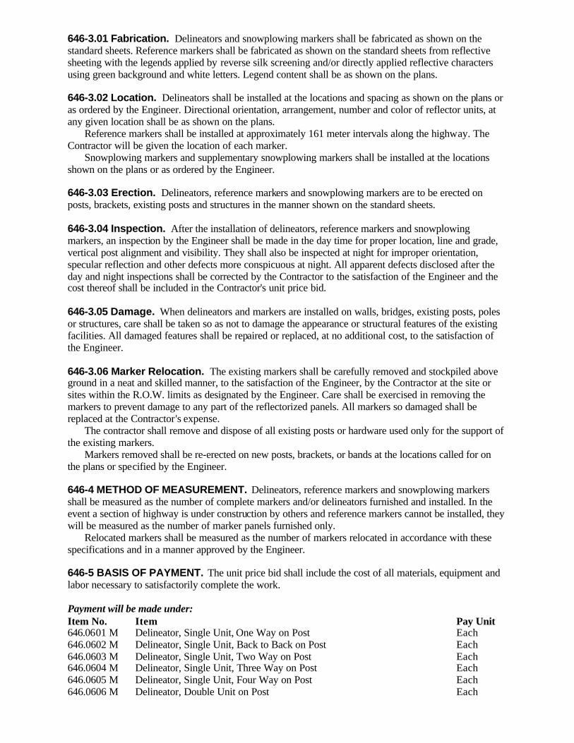
646-3.01 Fabrication. Delineators and snowplowing markers shall be fabricated as shown on the standard sheets. Reference markers shall be fabricated as shown on the standard sheets from reflective sheeting with the legends applied by reverse silk screening and/or directly applied reflective characters using green background and white letters. Legend content shall be as shown on the plans. 646-3.02 Location. Delineators shall be installed at the locations and spacing as shown on the plans or as ordered by the Engineer. Directional orientation, arrangement, number and color of reflector units, at any given location shall be as shown on the plans. Reference markers shall be installed at approximately 161 meter intervals along the highway. The Contractor will be given the location of each marker. Snowplowing markers and supplementary snowplowing markers shall be installed at the locations shown on the plans or as ordered by the Engineer. 646-3.03 Erection. Delineators, reference markers and snowplowing markers are to be erected on posts, brackets, existing posts and structures in the manner shown on the standard sheets. 646-3.04 Inspection. After the installation of delineators, reference markers and snowplowing markers, an inspection by the Engineer shall be made in the day time for proper location, line and grade, vertical post alignment and visibility. They shall also be inspected at night for improper orientation, specular reflection and other defects more conspicuous at night. All apparent defects disclosed after the day and night inspections shall be corrected by the Contractor to the satisfaction of the Engineer and the cost thereof shall be included in the Contractor's unit price bid. 646-3.05 Damage. When delineators and markers are installed on walls, bridges, existing posts, poles or structures, care shall be taken so as not to damage the appearance or structural features of the existing facilities. All damaged features shall be repaired or replaced, at no additional cost, to the satisfaction of the Engineer. 646-3.06 Marker Relocation. The existing markers shall be carefully removed and stockpiled above ground in a neat and skilled manner, to the satisfaction of the Engineer, by the Contractor at the site or sites within the R.O.W. limits as designated by the Engineer. Care shall be exercised in removing the markers to prevent damage to any part of the reflectorized panels. All markers so damaged shall be replaced at the Contractor's expense. The contractor shall remove and dispose of all existing posts or hardware used only for the support of the existing markers. Markers removed shall be re-erected on new posts, brackets, or bands at the locations called for on the plans or specified by the Engineer. 646-4 METHOD OF MEASUREMENT. Delineators, reference markers and snowplowing markers shall be measured as the number of complete markers and/or delineators furnished and installed. In the event a section of highway is under construction by others and reference markers cannot be installed, they will be measured as the number of marker panels furnished only. Relocated markers shall be measured as the number of markers relocated in accordance with these specifications and in a manner approved by the Engineer. 646-5 BASIS OF PAYMENT. The unit price bid shall include the cost of all materials, equipment and labor necessary to satisfactorily complete the work. Payment will be made under: Item No. Item Pay Unit 646.0601 M Delineator, Single Unit, One Way on Post Each 646.0602 M Delineator, Single Unit, Back to Back on Post Each 646.0603 M Delineator, Single Unit, Two Way on Post Each 646.0604 M Delineator, Single Unit, Three Way on Post Each 646.0605 M Delineator, Single Unit, Four Way on Post Each 646.0606 M Delineator, Double Unit on Post Each

646.0607 M Delineator, Single Unit, Band or Bracket Mounted Each 646.0608 M Delineator, Double Unit, Band or Bracket Mounted Each 646.0609 M Delineator, Single Unit, Back to Back, Band or Bracket Mounted Each 646.0610 M Delineator, Single Unit, Two Way, Band or Bracket Mounted Each 646.0611 M Delineator, Single Unit, Three Way, Band or Bracket Mounted Each 646.0612 M Delineator, Single Unit, Four Way, Band or Bracket Mounted Each 646.0623 M Delineator, White, Single Unit, One Way on Flexible Post Each 646.0624 M Delineator, White, Single Unit, Back to Back, on Flexible Post Each 646.0625 M Delineator, White, Double Unit on Flexible Post Each 646.0633 M Delineator, Yellow, Single Unit, One Way on Flexible Post Each 646.0634 M Delineator, Yellow, Single Unit, Back to Back, on Flexible Post Each 646.0635 M Delineator, Yellow, Double Unit on Flexible Post Each 646.0701 M Reference Marker, 1.2 m Mounting Height Each 646.0702 M Reference Marker, 2.1 m Mounting Height Each 646.0703 M Reference Marker, Band or Bracket Mounted Each 646.0704 M Reference Marker, On Existing Post Each 646.0705 M Reference Marker, Furnish Panel Only Each 646.0801 M Snowplowing Marker, Single Unit Each 646.0802 M Snowplowing Marker, Double Unit Each 646.0803 M Supplementary Snowplowing Marker Each 646.09 M Marker-Relocation Each SECTION 647 - REMOVING, STORING AND RELOCATING SIGNS 647-1 DESCRIPTION. This work shall include the removal, or removal and storage, or relocation of existing State signs and/or sign structures designated on the plans or specified by the Engineer. The sign components shall include sign panels, stringers, vertical brackets, miscellaneous hardware used solely for the support of the designated sign panels, upright supports, bracing and structures. 647-2 MATERIALS. All materials used in this work shall meet the requirements of §645-2. 647-3 CONSTRUCTION DETAILS 647-3.01 Removal of Signs. Existing traffic signs requiring removal, but not storage, shall become the property of the Contractor and shall be removed from the work site in a neat and skillful manner to the satisfaction of the Engineer. 647-3.02 Removal and Storage of Signs. Existing traffic signs shall be removed and stockpiled off the ground in a neat and skillful manner, to the satisfaction of the Engineer, by the Contractor at the site or sites within the R.O.W. limits as approved by the Engineer. 647-3.03 Removal of Concrete Sign Footings. All concrete sign footings shall be completely removed, or if allowed by the Engineer, shall be cut to a depth of 0.3 meters below existing ground and be replaced with suitable material as specified by the Engineer. 647-3.04 Relocation of Signs. Existing sign panels shall be removed and stockpiled off the ground in a neat and skillful manner by the Contractor to the satisfaction of the Engineer, at the site or sites within the R.O.W. limits as designated by the Engineer. Care shall be exercised in removing the sign panels to prevent damage to any part of the reflectorized sign face or characters, or the existing stringers or stiffeners. Any damage shall be repaired or the damaged part replaced to the satisfaction of the Engineer at the Contractor's expense. Existing sign posts shall become the property of the Contractor and shall be removed from the work site in a neat and skillful manner. The Contractor shall erect new sign posts and mount the existing sign panels at the locations shown on the plans or specified by the Engineer. The requirements of §645-3, Construction Details, shall apply to this work.

647-4 METHOD OF MEASUREMENT. The quantity to be paid for will be the number of completely removed or relocated installations having sign areas of the following sizes: Size A: 0.0 to 1.0 Square Meters Size D: 4.1 to 10.0 Square Meters Size B: 1.1 to 2.0 Square Meters Size E: Over 10.0 Square Meters Size C: 2.1 to 4.0 Square Meters All Overhead Sign Panels (Any Size) 647-5 BASIS OF PAYMENT. The unit price bid for removing or removing and storing or relocating an existing installation shall be compensation in full for the furnishing of all labor, equipment, and materials necessary described in this section. Payment will be made under: Item No. Item Pay Unit 647.01 M Removal of Signs - Size A (0.0 to 1.0 S.M.) Each 647.02 M Removal of Signs - Size B (1.1 to 2.0 S.M.) Each 647.03 M Removal of Signs - Size C (2.1 to 4.0 S.M.) Each 647.04 M Removal of Signs - Size D (4.1 to 10.0 S.M.) Each 647.05 M Removal of Signs - Size E (Over 10.0 S.M.) Each 647.06 M Removal and Storage of Signs Size A (0.0 to 1.0 S.M.) Each 647.07 M Removal and Storage of Signs Size B (1.1 to 2.0 S.M.) Each 647.08 M Removal and Storage of Signs Size C (2.1 to 4.0 S.M.) Each 647.09 M Removal and Storage of Signs Size D (4.1 to 10.0 S.M.) Each 647.10 M Removal and Storage of Signs Size E (Over 10.0 S.M.) Each 647.11 M Relocating Signs Size A (0.0 to 1.0 S.M.) Each 647.12 M Relocating Signs Size B (1.1 to 2.0 S.M.) Each 647.13 M Relocating Signs Size C (2.1 to 4.0 S.M.) Each 647.14 M Relocating Signs Size D (4.1 to 10.0 S.M.) Each 647.15 M Relocating Signs Size E (Over 10.0 S.M.) Each 647.18 M Removal of Overhead Sign Panels Each 647.19 M Removal and Storage of Overhead Sign Panels Each 647.20 M Removal of Cantilever Sign Structure Each 647.21 M Removal of Single Span Sign Structure Each 647.22 M Removal of Multi-Span Sign Structure Each SECTION 648 - SUBSURFACE EXPLORATIONS 648-1 DESCRIPTION. This work shall consist of furnishing equipment, drilling for soil and rock samples, and preparing a driller's log in accordance with these specifications and the direction of the Engineer. 648-2 MATERIALS. Materials for this work shall meet the requirements of the following Subsections of Section 700 - Materials Details: Drill Rigs 732-01 Drive Pipe 732-02 Casing 732-03 Samplers 732-04 Thin-Walled Sample Tubes 732-05 Coring Bits 732-06 Sample Storage Bags 732-07 Sample Jars 732-08 Jar Cartons 732-09 Boulder and Rock Core Boxes 732-10 Open Well Piezometers 732-11 Grout 732-12

648-3 CONSTRUCTION DETAILS 648-3.01 General. This work shall consist of furnishing equipment, clearing of all dr ill holes in accordance with New York State Department of Public Service Rule 753, drilling for soil and rock samples, back filling all drill holes to the satisfaction of the Engineer, and preparing a driller's log in accordance with these specifications. Any proposed variation from the methods and techniques in the specifications shall be submitted in writing by the Contractor to the Engineer who shall forward the proposal to the Director of the Geotechnical Engineering Bureau for review. Approval, if granted, will be based on the decision of the Director of the Geotechnical Engineering Bureau as to the capabilities of the proposed variation to provide satisfactory samples and subsurface information. If granted, this approval will remain in force only so long as all conditions set forth in the approval are met and satisfactory results are obtained. In the event unsatisfactory results are obtained, the approval will be withdrawn and all remaining work shall be completed in accordance with this specification. Boring work shall not commence until all equipment stated in the proposal is on the project and approved. In addition, the following shall apply: A. Furnishing equipment for Making Borings. The Contractor shall furnish the number of drill rigs, conforming to §732-01, stated in the proposal or work order, maintain this equipment, and remove it from the site at the time indicated by the Engineer. All equipment shall be acceptable to the Engineer. B. Driller's Logs. The forms for the driller's logs, Form 282e, will be furnished by the State and shall have the following information legibly printed on them by the Contractor: Region County Contractor Name Contract Number Project Identification Number (PIN) Project Name Date Started and Finished Hole Number Weight and Fall of Hammer (Casing) Weight and Fall of Hammer (Sampler) Casing and Sampler Size Inspector Name (Regional Geotechnical Engineer on Log) Structure Name/Number Penetration Records (Blows on Casing, Drive Pipe and Sampler) Sample numbers Groundwater Data Depth at which drill water was first used Depth at which groundwater was first encountered Depth to groundwater at the beginning and end of each day's operation Rock Core Length of Run Percent Recovery Number of Pieces Depth Core Obtained Size of Core Obtained Type of Core Barrel All pertinent remarks and comments

The hole designation on the final log and sample containers should reflect the actual method of progressing the hole. Any change in hole designation (due to an alternate hole progression method) shall be forwarded to the Engineer in writing in a timely manner. Provide all measurements and dimensions in metric units on the final log . Ensure that the completed driller's log is signed by the drill rig operator, the drill rig inspector, and the Chief Inspector. Deliver the samples and a copy of the completed driller's log to the location indicated in the Contract documents, between the hours of 8:00 A.M. and 3:00 P.M. , within five working days following completion of the hole, except holidays. In addition, deliver another copy of the completed driller's log to the Departmental Geotechnical Engineer. Submit the original copy of the completed driller's log to the Engineer. C. Groundwater Determinations. The level at which groundwater is first encountered in the borings shall be noted. Water level readings shall be taken at the end of each day after the last sample has been taken and the sample and rods have been removed. No soil shall be left in the casing at the end of the day. Do not fill the casing with water unless there is a need to compensate for a condition such as running sand. Measure and record the change in water level when resuming work. Capped borings shall be vented. Groundwater levels shall be measured before and after the casing or drive pipe is pulled. Each water level reading shall be recorded showing the date and time the reading was made, the depth of the drive pipe or casing, and the depth to water. Any loss or gain of water in the boring, except that caused by deliberately introducing water and/or inserting or removing tools, shall be recorded. This record shall show the date and time the loss or gain is noted, the depth of the casing and the depth to water. The height of artesian rise shall be recorded. All water level readings and related data shall be recorded on the boring logs under “Remarks”. If necessary, additional forms shall be used for recording groundwater data. Artesian pressures shall be permanently sealed at the elevation at which they were encountered. This seal shall be satisfactory to the Engineer before casing is removed from the hole. 648-3.02 Split Barrel Samples A. Progressing the Hole. The hole shall be progressed by advancing flush-joint casing, flush-coupled casing, or extra-strength drive pipe by driving or drilling, or where permitted, by a drilling mud process or by using a hollow flight auger. When driven casing is used a 136.3 kg (" 3 percent) hammer falling freely 450 mm shall be used. Actuate the hammer by means of a rope and cathead, or by automatic hammer, when casing or drive pipe is driven. Casing refusal shall be considered as 300 blows for less than 300 mm of penetration. When refusal is encountered, the casing shall be cleaned and a sample shall be attempted , if no sample is recovered, coring will commence. Prior to sampling, the drill hole shall be cleaned to the sampling elevation by using equipment that will not disturb the material to be sampled. Bottom discharge bits, including samplers, will not be allowed. A roller bit may be used as a clean out tool if it is of a type that deflects water to the sides rather than downward into the material to be sampled. The Engineer may order a new roller bit at any time he deems the one in use to be unacceptable. “N” size drill rods or larger shall be used in 76.2 mm or larger inside diameter casing. The Engineer shall be advised of the time of the last sampling operation so he may be present when the hole is measured for payment purposes. B. Sampling. Samples shall be taken at every change in stratum but in no case at intervals greater than 1.5 m. Continuous sampling may be directed by the Engineer. The sampler shall be placed on the bottom of the cleaned out hole and then driven 450 mm with a 136.3 kg (" 3 percent) hammer falling freely 450 mm. Actuate the hammer by means of a rope and cathead, or by automatic hammer. When the Standard Penetration Test (SPT) is required, use equipment and procedures conforming to ASTM D1586-84, except as modified by this specification. The number of blows required to drive the sampler each increment of 150 mm shall be recorded. If refusal is encountered before the desired sample length is attained, and the sampler proves to have no recovery, the sampler shall be removed from the hole and core drilling started; however, if refusal is

encountered and the material retained represents the best obtainable sample as determined by the Engineer, the hole may be progressed to the next sample elevation or change in soil strata . Refusal shall be 50 hammer blows for less than 150 mm of penetration for the 136.3 kg hammer. When the SPT is used, refusal shall be as defined in ASTM D1586-84. When a recovery of less than 150 mm of sample in a split barrel sampler is retrieved, the sampler shall be re-driven at the same elevation in an attempt to obtain more material. Only the first set of blows shall be recorded on the boring log, but a note shall be included under “Remarks” indicating that a second sampling attempt was made. The Engineer may direct that a basket or other spring type retainer be used on any or all sampling attempts. Flap or trap valves will only be used when specifically directed by the Engineer. When sampling material below the water table, the hole shall be kept full of fluid during the removal of tools to prevent flowback, unless otherwise directed by the Engineer. All samples, regardless of the amount of recovery, shall become the property of the State and shall be packaged, transported and delivered in accordance with this specification. C. Marking, Packaging and Transporting Sample. Samples shall be placed in tied plastic storage bags placed in jars conforming to §732-08 in such a manner so as to maintain the natural structure of the sample. The jar shall be labeled to show the project name, PIN, sample number, hole number, and the depths from which the sample was taken. Jars shall be placed in cartons conforming to §732-09. Samples must be protected from freezing or extreme heat. The samples shall be delivered by the Contractor to the location indicated in the Contract documents between the hours of 8:00 A.M. and 3:00 P.M., within five working days following completion of the hole, excepting holidays. If samples are not delivered in a timely manner, work will be suspended until the samples have been delivered as required by the contract. D. Acceptance. Samples having less than 150 mm of recovery or more than 50 mm of wash material will be considered unacceptable unless, in the judgment of the Engineer, the actual recovery represents the best sample obtainable. All samples shall become the property of the State. 648-3.03 Thin-Walled Tube Samples A. Progressing the Hole. The hole shall be a minimum of 100 mm in diameter. Drilling mud may be used if permitted in writing by the Engineer. Hollow stem augers will not be allowed. The hole shall be cleaned using methods and equipment which will not disturb the soil to be sampled. Bottom discharge bits, including samplers, will not be allowed. The 50 mm of soil directly above the sampling elevation shall be removed with a clean-out jet auger without the use of water. “N” size drill rod or larger shall be used. B. Sampling. Thin-walled tube samples shall be taken in the strata designated by the Engineer. Samples shall be recovered with a stationary piston type sampler or a hydraulically operated piston sampler, modified to accept the thin-walled tubes specified in §732-05. Samplers with piston rods extending to the ground surface must be provided with clamps which positively lock the piston against upward travel during lowering of the sampler until the sampling depth is reached. During the press the piston rods shall be locked in a stationary position to eliminate any movements either up or down. In addition, the sampler shall also be provided with positive locks to secure the piston rods prior to removal of the sampler after penetration. At the elevation to be sampled, the tube shall be pressed into the soil with a continuous motion a distance of 450 mm. Care must be taken to allow air and water to flow freely through the vent thus preventing compression of the soil sample. After pressing to the required depth and waiting for 5 minutes, the sampler shall be carefully rotated and removed from the hole. During the removal of the sampler the hole shall be kept full of fluid. Before the thin-walled tube is removed from the piston, the piston rod shall be backed off to admit air past the flattened threads to break the vacuum. For other approved types of equipment, the necessary vacuum breaking measures shall be taken. The length of sample in the tube and also the distance pressed, shall be measured and recorded. Should a thin-walled sample not be retained, a 50 mm driven sample shall be taken. The bottom of the sample shall be carefully squared off at least 25 mm back from the end of the tube and a wax seal, approximately 25 mm thick, shall be poured in the bottom end of the tube. The soil at the
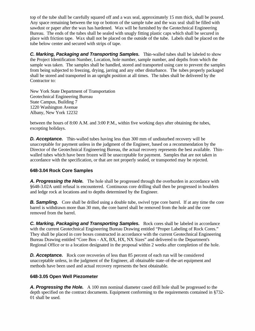
top of the tube shall be carefully squared off and a wax seal, approximately 15 mm thick, shall be poured. Any space remaining between the top or bottom of the sample tube and the wax seal shall be filled with sawdust or paper after the wax has hardened. Wax will be furnished by the Geotechnical Engineering Bureau. The ends of the tubes shall be sealed with snugly fitting plastic caps which shall be secured in place with friction tape. Wax shall not be placed on the outside of the tube. Labels shall be placed on the tube below center and secured with strips of tape. C. Marking, Packaging and Transporting Samples. Thin-walled tubes shall be labeled to show the Project Identification Number, Location, hole number, sample number, and depths from which the sample was taken. The samples shall be handled, stored and transported using care to prevent the samples from being subjected to freezing, drying, jarring and any other disturbance. The tubes properly packaged shall be stored and transported in an upright position at all times. The tubes shall be delivered by the Contractor to: New York State Department of Transportation Geotechnical Engineering Bureau State Campus, Building 7 1220 Washington Avenue Albany, New York 12232 between the hours of 8:00 A.M. and 3:00 P.M., within five working days after obtaining the tubes, excepting holidays. D. Acceptance. Thin-walled tubes having less than 300 mm of undisturbed recovery will be unacceptable for payment unless in the judgment of the Engineer, based on a recommendation by the Director of the Geotechnical Engineering Bureau, the actual recovery represents the best available. Thin-walled tubes which have been frozen will be unacceptable for payment. Samples that are not taken in accordance with the specification, or that are not properly sealed, or transported may be rejected. 648-3.04 Rock Core Samples A. Progressing the Hole. The hole shall be progressed through the overburden in accordance with §648-3.02A until refusal is encountered. Continuous core drilling shall then be progressed in boulders and ledge rock at locations and to depths determined by the Engineer. B. Sampling. Core shall be drilled using a double tube, swivel type core barrel. If at any time the core barrel is withdrawn more than 30 mm, the core barrel shall be removed from the hole and the core removed from the barrel. C. Marking, Packaging and Transporting Samples. Rock cores shall be labeled in accordance with the current Geotechnical Engineering Bureau Drawing entitled “Proper Labeling of Rock Cores.” They shall be placed in core boxes constructed in accordance with the current Geotechnical Engineering Bureau Drawing entitled “Core Box - AX, BX, HX, NX Sizes” and delivered to the Department's Regional Office or to a location designated in the proposal within 2 weeks after completion of the hole. D. Acceptance. Rock core recoveries of less than 85 percent of each run will be considered unacceptable unless, in the judgment of the Engineer, all obtainable state-of-the-art equipment and methods have been used and actual recovery represents the best obtainable. 648-3.05 Open Well Piezometer A. Progressing the Hole. A 100 mm nominal diameter cased drill hole shall be progressed to the depth specified on the contract documents. Equipment conforming to the requirements contained in §732-01 shall be used.
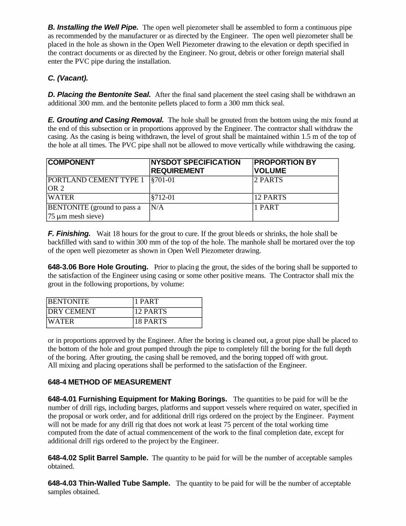
B. Installing the Well Pipe. The open well piezometer shall be assembled to form a continuous pipe as recommended by the manufacturer or as directed by the Engineer. The open well piezometer shall be placed in the hole as shown in the Open Well Piezometer drawing to the elevation or depth specified in the contract documents or as directed by the Engineer. No grout, debris or other foreign material shall enter the PVC pipe during the installation. C. (Vacant). D. Placing the Bentonite Seal. After the final sand placement the steel casing shall be withdrawn an additional 300 mm. and the bentonite pellets placed to form a 300 mm thick seal. E. Grouting and Casing Removal. The hole shall be grouted from the bottom using the mix found at the end of this subsection or in proportions approved by the Engineer. The contractor shall withdraw the casing. As the casing is being withdrawn, the level of grout shall be maintained within 1.5 m of the top of the hole at all times. The PVC pipe shall not be allowed to move vertically while withdrawing the casing. COMPONENT NYSDOT SPECIFICATION
REQUIREMENT PROPORTION BY VOLUME
PORTLAND CEMENT TYPE 1 OR 2
§701-01 2 PARTS
WATER §712-01 12 PARTS BENTONITE (ground to pass a 75 :m mesh sieve)
N/A 1 PART
F. Finishing. Wait 18 hours for the grout to cure. If the grout bleeds or shrinks, the hole shall be backfilled with sand to within 300 mm of the top of the hole. The manhole shall be mortared over the top of the open well piezometer as shown in Open Well Piezometer drawing. 648-3.06 Bore Hole Grouting. Prior to placing the grout, the sides of the boring shall be supported to the satisfaction of the Engineer using casing or some other positive means. The Contractor shall mix the grout in the following proportions, by volume: BENTONITE 1 PART DRY CEMENT 12 PARTS WATER 18 PARTS or in proportions approved by the Engineer. After the boring is cleaned out, a grout pipe shall be placed to the bottom of the hole and grout pumped through the pipe to completely fill the boring for the full depth of the boring. After grouting, the casing shall be removed, and the boring topped off with grout. All mixing and placing operations shall be performed to the satisfaction of the Engineer. 648-4 METHOD OF MEASUREMENT 648-4.01 Furnishing Equipment for Making Borings. The quantities to be paid for will be the number of drill rigs, including barges, platforms and support vessels where required on water, specified in the proposal or work order, and for additional drill rigs ordered on the project by the Engineer. Payment will not be made for any drill rig that does not work at least 75 percent of the total working time computed from the date of actual commencement of the work to the final completion date, except for additional drill rigs ordered to the project by the Engineer. 648-4.02 Split Barrel Sample. The quantity to be paid for will be the number of acceptable samples obtained. 648-4.03 Thin-Walled Tube Sample. The quantity to be paid for will be the number of acceptable samples obtained.

648-4.04 Rock Core Drilling. The quantity to be paid for will be the number of linear meters drilled from which acceptable core was obtained. Measurement for payment shall be made in the presence of the Engineer. 648-4.05 Drill Hole (65 mm and 100 mm diameter). The quantity to be paid for will be the number of linear meters of boring progressed in overburden, less a deduction equal to the specified sampling interval for each unacceptable sample. Measurement shall be made from the surface elevation where the boring starts (including top of bridge deck or the water surface if working from a floating platform) at each hole. Measurement for payment shall be made in the presence of the Engineer. 648-4.06 Open Well Piezometer. The quantity to be paid for will be the number of linear meters of PVC pipe satisfactorily installed in accordance with this specification, measured from the top of the pipe to the bottom of the slotted screen. 648-4.07 Bore Hole Grouting ( 65 mm and 100 mm diameter). The quantity to be paid for will be the number of linear meters of drill hole grouted in accordance with these specifications. 648-5 BASIS OF PAYMENT 648-5.01 Furnishing Equipment for Making Borings (on land or water). The unit price bid for each drill rig shall include the cost of all labor, materials and equipment including barges, platforms and support vessels necessary to furnish, transport and maintain the drill rig, and dismantling and removing the equipment. 648-5.02 Split Barrel Sample. The unit price bid per sample shall include the cost of all labor, material and equipment necessary to obtain, mark, package and deliver the sample. The jars, cartons and samples shall become the property of the State. 648-5.03 Thin-Walled Tube Sample. The unit price bid per sample shall include the cost of all labor, materials and equipment necessary to obtain, mark, package and deliver the sample. The tubes and samples shall become the property of the State. 648-5.04 Rock Core Drilling. The unit price bid per meter shall include the cost of all labor, material and equipment necessary to obtain, mark, package and deliver the samples. The core boxes shall become the property of the State. 648-5.05 Drill Hole (65 mm and 100 mm diameter). The unit price bid per meter shall include the cost of all labor, clearing of all drill holes in accordance to New York State Department of Public Service Rule 753, and material and equipment used to progress the hole from which an acceptable sample or samples were obtained and acceptably recorded on a driller's log. The unit price bid shall be based on 15 meter incremental depths as follows: 0 - 15 meters 15 - 30 meters 30 - 45 meters 45 - 60 meters over 60 meters 648-5.06 Open Well Piezometer. The unit price bid for this item shall include the cost of all labor, materials and equipment necessary to satisfactorily install and protect the open well piezometer. The Contractor will receive full payment after the open well piezometer has been approved by the Engineer. 648-5.07 Bore Hole Grouting (65 mm and 100 mm diameter). The unit price bid for grouting borings shall include the cost of furnishing all labor, materials and equipment necessary to complete the work as required by these specifications. The cost for progressing the boring will be paid under its appropriate item. Payment will be made under: Item No. Item Pay Unit
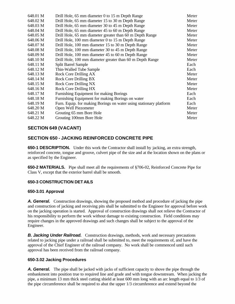
648.01 M Drill Hole, 65 mm diameter 0 to 15 m Depth Range Meter 648.02 M Drill Hole, 65 mm diameter 15 to 30 m Depth Range Meter 648.03 M Drill Hole, 65 mm diameter 30 to 45 m Depth Range Meter 648.04 M Drill Hole, 65 mm diameter 45 to 60 m Depth Range Meter 648.05 M Drill Hole, 65 mm diameter greater than 60 m Depth Range Meter 648.06 M Drill Hole, 100 mm diameter 0 to 15 m Depth Range Meter 648.07 M Drill Hole, 100 mm diameter 15 to 30 m Depth Range Meter 648.08 M Drill Hole, 100 mm diameter 30 to 45 m Depth Range Meter 648.09 M Drill Hole, 100 mm diameter 45 to 60 m Depth Range Meter 648.10 M Drill Hole, 100 mm diameter greater than 60 m Depth Range Meter 648.11 M Split Barrel Sample Each 648.12 M Thin-Walled Tube Sample Each 648.13 M Rock Core Drilling AX Meter 648.14 M Rock Core Drilling BX Meter 648.15 M Rock Core Drilling NX Meter 648.16 M Rock Core Drilling HX Meter 648.17 M Furnishing Equipment for making Borings Each 648.18 M Furnishing Equipment for making Borings on water Each 648.19 M Furn. Equip. for making Borings on water using stationary platform Each 648.20 M Open Well Piezometer Meter 648.21 M Grouting 65 mm Bore Hole Meter 648.22 M Grouting 100mm Bore Hole Meter SECTION 649 (VACANT) SECTION 650 - JACKING REINFORCED CONCRETE PIPE 650-1 DESCRIPTION. Under this work the Contractor shall install by jacking, an extra strength, reinforced concrete, tongue and groove, culvert pipe of the size and at the location shown on the plans or as specified by the Engineer. 650-2 MATERIALS. Pipe shall meet all the requirements of §706-02, Reinforced Concrete Pipe for Class V, except that the exterior barrel shall be smooth. 650-3 CONSTRUCTION DETAILS 650-3.01 Approval A. General. Construction drawings, showing the proposed method and procedure of jacking the pipe and construction of jacking and receiving pits shall be submitted to the Engineer for approval before work on the jacking operation is started. Approval of construction drawings shall not relieve the Contractor of his responsibility to perform the work without damage to existing construction. Field conditions may require changes in the approved drawings and such changes shall be subject to the approval of the Engineer. B. Jacking Under Railroad. Construction drawings, methods, work and necessary precautions related to jacking pipe under a railroad shall be submitted to, meet the requirements of, and have the approval of the Chief Engineer of the railroad company. No work shall be commenced until such approval has been received from the railroad company. 650-3.02 Jacking Procedures A. General. The pipe shall be jacked with jacks of sufficient capacity to shove the pipe through the embankment into position true to required line and grade and with tongue downstream. When jacking the pipe, a minimum 13 mm thick steel cutting shield at least 600 mm long with an arc length equal to 1/3 of the pipe circumference shall be required to abut the upper 1/3 circumference and extend beyond the

forward end of the pipe being jacked. The outside radius of this shield shall not exceed the outside radius of the pipe. Excavation ahead of the pipe shall not be permitted to progress beyond the end of the shield being used. B. Jacking Under Railroad. Rail hangers shall be installed by railroad company forces prior to the jacking operations, unless the Engineer is advised otherwise by the railroad company. The rail hangers will not be removed by railroad forces until all voids in the embankment as a result of the jacking operation, have been filled by the Contractor to the satisfaction of the railroad company. 650-3.03 Contractor Responsibility. The Contractor shall be held responsible for surface subsidence and damage or disturbance to adjacent property and facilities that may result from his construction methods. In case loose material is encountered and cave-ins occur or are anticipated, all jacking will be discontinued, approved shoring sha ll be provided and all voids filled either by pressure grouting or other approved methods before jacking is continued. Field conditions may require that the actual jacking operations be continued without interruption in order to prevent undermining the roadway or the railroad roadbed and tracks. Should the Engineer permit interruption of jacking operations, the Contractor shall provide bulkheads and dewatering measures as approved by the Engineer. 650-3.04 Railroad Responsibility. Any settlement or upheaval of the railroad tracks resulting from the pipe installation and occurring within one year from the date the work is completed, will be corrected by the railroad company. 650-4 METHOD OF MEASUREMENT. The quantity to be paid for under this work will be the number of linear meters of extra strength reinforced concrete culvert pipe jacked into place and measured in its final position. 650-5 BASIS OF PAYMENT 650-5.01 General. The unit price bid per linear meter shall include the cost of jacking the pipe; sheeting, bracing and flooring the jacking and receiving pits; excavation and backfill; pressure grouting; construction drawings; and all labor, materials and equipment (including dewatering if required) necessary to complete the work in accordance with the plans and specifications or directions of the Engineer; except the pipe which will be paid for separately under the contract item for Reinforced Concrete Pipe Class V. Rail hangers (if required) shall be installed and removed by railroad company forces at no cost to the Contractor. No extra payment of any sort will be made for premium time which may be required under this work, but the cost thereof shall be included in the unit price bid. No partial or final payment for jacking pipe under a railroad will be made until the work has been approved by the respective railroad company. Costs incurred by the railroad company to correct settlement or upheaval of the railroad tracks resulting from the pipe installation and occurring within one year from the date of work is completed, will be reimbursed to the railroad company directly by the State at not cost to the Contractor. Payment will be made under: Item No. Item Pay Unit 650.01nn M Jacking Reinforced Concrete Pipe Under Railroad Meter 650.02nn M Jacking Reinforced Concrete Pipe Under Highway Meter Refer to the Contract Proposal for full item number and full description. SECTION 651 - COMMUNICATION FACILITIES 651-1 DESCRIPTION. The work in this section shall include special construction of communication facilities which are required for outside agencies such as police and fire departments. The construction details for this work will be covered by special provisions in the contract documents.

SECTION 652 - FURNISHING AND APPLYING SALTS 652-1 DESCRIPTION. Under this work the Contractor shall furnish and apply salt for soil stabilization, as a dust palliative or for other purposes as specified. 652-2 MATERIALS. Materials for this work shall conform to the requirements of the following subsections of Section 700 - Materials: Calcium Chloride 712-02 Sodium Chloride 712-03 652-3 CONSTRUCTION DETAILS 652-3.01 Stabilized Gravel Surface Course. The Contractor shall apply salt for stabilization in accordance with the construction details specified in §411-3. 652-3.02 Dust Control. The Contractor shall apply salt on the highway to control dust at the locations and during periods as the Engineer may direct. The salt shall be applied on the dampened road surface by means of approved line spreader or equal equipment. An approved sprinkler or other approved method may be used to dampen the road surface. The recommended application rates for calcium chloride are as follows: 0.8 kg/m2 per application 2.2 kg/m2 per year 652-4 METHOD OF MEASUREMENT. Salt shall be measured by the number of the metric tons furnished and applied. 652-5 BASIS OF PAYMENT. The unit price bid per metric ton shall include all labor, material and equipment necessary to complete the work including necessary water to dampen the road surface. Payment will be made under: Item No. Item Pay Unit 652.01 M Furnishing and Applying Calcium Chloride Metric Ton 652.02 M Furnishing and Applying Sodium Chloride Metric Ton SECTION 653 (VACANT) SECTION 654 IMPACT ATTENUATORS 654-1 DESCRIPTION. The Contractor shall furnish and install, remove and dispose, remove and store, relocate, or refurbish impact attenuators of the indicated types and sizes at or from the locations indicated in the Contract Documents or those directed in accordance with these specifications, the Contract Documents, materials details, manufacturer’s directions and drawings, and the directions of the Engineer. 654-2 MATERIALS. Materials shall conform to the following subsections of these specifications: Class A Concrete 501-2 White Pavement Marking Paints 640-2 Concrete Grouting Material 701-05 Anchoring Material- Chemically Curing 701-07 Epoxy Coated Bar Reinforcement, Grade 420 709-04 Sodium Chloride 712-03 Inertial Barrier Modules 712-07 Impact Attenuator, Reusable, HDPE Cylinders and Cables 712-18 Impact Attenuator, Quad Beam Type with Expendable Modules 712-19
Impact Attenuator, Corrugated Beam Type with Metal Tearing Strips 712-20 Galvanized Coating and Repair Methods 719-01 Aluminum Sign Panels 730-01 Reflective Sheeting 730-05 654-3 CONSTRUCTION DETAILS. 654-3.01 General. The following shall apply to all impact attenuators to be installed under this section. A Drawings. Prior to installing any materials required under this section, the Contractor shall submit three (3) copies of the manufacturer’s drawings, modified as necessary to reflect site conditions, to the Engineer. The submission shall include certification that modifications made to reflect site conditions will not impair the satisfactory performance of the impact attenuator. Manufacturer’s drawings, modified as necessary to reflect site conditions, will be referred to in this section as “working drawings.” Working drawings will take precedence over manufacturer’s drawings. Working drawings shall show supports, transition pieces, connections, miscellaneous parts, concrete or steel back-up structure, and anchorages not detailed in the plans, but which are necessary to develop the full performance of the impact attenuator. The Contractor shall not commence installation of the impact attenuator earlier than five (5) days following submission of the above mentioned working or manufacturer’s drawings unless authorized by the Engineer to do so. B Manuals. In addition to the drawings mentioned above, the Contractor shall deliver to the Engineer three (3) copies of design manuals, installation manuals, parts lists, and maintenance manuals prepared for each type impact attenuator being installed. The Contractor shall not commence installation of the impact attenuator earlier than five (5) days following submission of the above mentioned manuals, unless authorized by the Engineer to do so. C Coordination with Other Work. The work under this section shall be coordinated with the removal or installation of shielded objects, guide rail and median barriers, impact attenuators or end terminals so as to minimize the time that motorists are exposed to unnecessary hazard. Also, the Contractor shall minimize exposure of vehicular traffic to the possibility of impact on the back-up structure. Unless modified in the contract documents, minimize shall mean seven (7) or fewer calender days. D Traffic Protection. Traffic control devices, such as cones, drums, lights, signs, barricades, or other articles directed by the Engineer shall be provided and maintained under their respective pay items. These devices shall not be removed until the impact attenuator, including required transition pieces, is fully operational. If the impact attenuator is to be installed in lighted areas, or in areas to be lighted, the mentioned traffic control devices shall not be removed unless the lighting system is operational. 654-3.02 Impact Attenuators Requiring Foundations. If the work of furnishing and installing impact attenuators requires the provision of a foundation slab, the following shall apply: A Excavation. Necessary excavation shall be performed in accordance with Section 203 of the Standard Specifications. If the foundation slab is to be installed in a pavement that is to remain in place in the completed project, the limits of excavation in such pavement shall be saw cut full depth prior to removal of the pavement and performance of the excavation work. Unless indicated otherwise, the limits of pavement excavation shall be 600 mm outside the perimeter of the foundation slab. B Foundation Slab. The Contractor shall construct the foundation slab and back-up structure at the locations shown, or where directed by the Engineer, to the dimensions indicated in the working or manufacturer’s drawings. The foundation slab shall be reinforced Class A concrete not less than the thickness indicated on the working drawings or manufacturer’s drawings, batched, formed, placed, finished, and cured in accordance with §501-3 Portland Cement Concrete, Construction Details. The size, length, and bending details of reinforcement shall be as shown in the foundation slab details in the

manufacturer’s drawings or in the working drawings, or as directed. If accelerators are needed, the Contractor shall submit the concrete mix design to the Materials Bureau for prior approval. B Foundation Slab. The Contractor shall construct the reinforced concrete foundation slab and back-up structure to the dimensions indicated in the working or manufacturer’s drawings. The foundation slab shall be not less than the thickness indicated on the working drawings, manufacturer’s drawings, or 200 mm, whichever is greatest. The concrete shall be Class A concrete batched in accordance with §501-3 Portland Cement Concrete, Construction Details. If accelerators are needed, the Contractor shall submit the concrete mix design to the Materials Bureau for prior approval. The concrete shall be formed, placed, finished, and cured in accordance with §502-3 Portland Cement Concrete Pavement, Construction Details. The reinforcing bars shall be in conformance to §709-04 Epoxy Coated Bar Reinforcement, Grade 420. The size, length, and bending details of reinforcement shall be as shown in the foundation slab details in the manufacturer’s drawings or in the working drawings. The minimum allowable reinforcing shall be #16 longitudinal bars, spacing 400 mm on centers, and #16 cross bars, spacing 2 meters on centers. Longitudinal bars shall be placed such that they will not be cut during anchorage installation. EI 02042 C Pavement Restoration. The excavated section of pavement between the new foundation slab and the limits of excavation shall be restored to the full height of the surrounding sound pavement in accordance with §402-3.05 Conditioning of Existing Surface, or in the manner directed by the Engineer. 654-3.03 Anchorages. The impact attenuator shall be anchored to the new foundation slab or existing concrete foundation as shown on the manufacturer’s drawings or the working drawings. Anchor bolts and studs not cast integrally into the new foundation slab shall be anchored with approved concrete expansion anchors, concrete grouting material conforming to §701-05, or approved chemically curing anchoring material conforming to §701-07. Such anchor bolts or studs shall be set into holes drilled with rotary impact drills of the size recommended by the manufacturer of the anchor. Core drills will not be acceptable. Care shall be taken that anchor studs projecting from the surface and exposed to foot or wheeled traffic be well marked by barricades, plastic drums, or protected by other means as approved by the Engineer. 654-3.04 Inertial Barrier Modules. The Contractor shall furnish and install Inertial Barrier Modules of the size and number required at the locations and to the configurations indicated on the contract plans, or at the locations and to the configurations directed by the Engineer. In addition to the requirements indicated in §654-3.01 General, the Contractor shall also paint and label the layout pattern and weights on paved surfaces using traffic or other durable paint. Glass beads will not be required. Either the metric weight or the U.S. customary weight, as directed by the Engineer, shall be marked. The 90 kg units shall be restrained from movement by mechanical means, or by other means as approved by the Engineer. 654-3.05 Impact Attenuator, Quad Beam Type with Expendable Modules. In addition to the requirements indicated in §654-3.01 General, §654-3.02 Impact Attenuators Requiring Foundation (if applicable,) and §654-3.03 Anchorages, the Contractor shall furnish and install Impact Attenuators, Quad Beam Type with Expendable Modules on existing or new foundations, as indicated, of the indicated width and length and at the locations indicated on the contract plans, in accordance with these specifications, the manufacturer’s directions and drawings, the working drawings, and the directions of the Engineer. Steel Tension Strut Backup Assemblies shall be used, except when protecting concrete piers, concrete parapets, concrete walls, or other rigid objects, in which case either the Steel Tension Strut Backup Assembly or the Concrete Backup Assembly shall be used, at the option of the Contractor. The

appropriate standard transition or special transition piece, if none of the standard transition pieces is appropriate, shall be furnished and installed. 654-3.06 Impact Attenuator, Reusable, HDPE Cylinders and Cable Type. In addition to the requirements indicated in §654-3.01 General, §654-3.02 Impact Attenuators Requiring Foundation and §654-3.03 Anchorages, the Contractor shall furnish and install Impact Attenuator, Reusable, HDPE Cylinders and Cable Type on existing or new foundations, as indicated, of the indicated number of cylinders of the required thicknesses in accordance with these specifications, the manufacturer’s directions, the working drawings, and the directions of the Engineer. In addition to the above, the base of concrete barriers and other simila r solid objects shall be cut back at a 45E angle, and transition pieces shall be provided on both sides between the backup structure and the concrete barrier or other similar object. 654-3.07 Impact Attenuator, Corrugated Beam Type with Metal Tearing Strips. The Contractor shall furnish and install Impact Attenuators, Corrugated Beam Type with Metal Tearing Strips on new or existing foundations, as indicated, of the indicated number of bays at the locations indicated in the contract documents in accordance with these specifications, the manufacturer’s instructions and drawings, the working drawings, and the directions of the Engineer. 654-3.08 Impact Attenuators, All Types, Remove and Dispose. The Contractor shall remove impact attenuators of the indicated type and associated foundation slabs, if required, from their existing locations. Upon removal, the impact attenuators and foundation slabs shall become the property of the Contractor, and the Contractor shall dispose of them in a manner and at a location approved by the Engineer. Holes in and other damage to the surfaces underlying the impact attenuator shall be repaired to the satisfaction of the engineer. Anchor bolts or studs that are no longer required or usable shall be removed or cut off flush with the surface. Voids resulting from the removal of foundation slabs shall be filled with compacted suitable material or compacted granular material, or other designated material as directed. 654-3.09 Impact Attenuators, All Types, Remove and Store. The Contractor shall remove impact attenuators of the indicated type from their existing locations with reasonable skill and care in a manner that preserves their condition. The impact attenuators shall remain the property of the State, and the Contractor shall store and protect them in a manner and at locations satisfactory to the Engineer. Damaged parts shall be replaced with like parts in satisfactory condition or repaired in a manner approved by the Engineer. If required, pavement slabs shall be removed and disposed in a manner and at locations satisfactory to the Engineer. Voids resulting from the removal of foundation slabs shall be filled with compacted suitable material or compacted granular material, or other designated material as directed. Holes and other damage to the surfaces underlying the impact attenuator shall be repaired to the satisfaction of the engineer. Anchor bolts or studs that are no longer required or usable shall be removed, or cut off flush with the surface. 654-3.10 Impact Attenuators, All Types, Relocate. The Contractor shall remove impact attenuators of the indicated type from their existing locations with reasonable skill and care in a manner that preserves their condition, and reinstall them at the same location or install them at another designated location. If required, the Contractor shall construct a new foundation slab. The impact attenuators shall remain the property of the State during the course of the work. If intermediate storage is required during the relocation, the Contractor shall store and protect impact attenuators in a manner and at locations approved by the Engineer. Damaged parts shall be replaced with like parts in satisfactory condition or be repaired in a manner approved by the Engineer. If required, pavement slabs shall be removed and disposed of in a manner and at locations satisfactory to the Engineer. Voids resulting from the removal of foundation slabs shall be filled with compacted suitable material, compacted granular material, or other designated material, as directed. Holes and other damage to the surfaces underlying the impact attenuator shall be repaired to the satisfaction of the Engineer. Anchor bolts or studs that are no longer required or usable shall be removed or cut off flush with the surface.

§654-3.01C Coordination with Other Work, §654-3.01D Traffic Protection, and §654-3.09 Impact Attenuators, All Types, Remove and Store shall apply. If required, a new foundation slab shall be constructed in accordance with the requirements of §654-3.02, Impact Attenuators Requiring Foundations. 654-3.11 Impact Attenuators, All Types, Refurbish. The contractor shall refurbish bays of designated impact attenuators of the indicated type in accordance with these specifications, the directions of the manufacturer, and as approved by the Engineer. Damaged parts shall be replaced with like parts in satisfactory condition or repaired to the satisfaction of the Engineer. §654-3.01C Coordination with Other Work, and §654-3.01D Traffic Protection shall apply. In addition, the Contractor shall repair the anchorages in accordance with §654-3.03 Anchorages, if they are damaged. 654-4 METHOD OF MEASUREMENT. 654-4.01 General. Measurement will be taken as the number of impact attenuators of the indicated type and size satisfactorily furnished and installed on existing foundations; as the number of impact attenuators of the indicated type and size satisfactorily furnished and installed on new foundation slabs; as the number of impact attenuators of the indicated type satisfactorily removed and disposed; as the number of impact attenuators of the indicated type satisfactorily removed and stored; as the number of impact attenuators of the indicated type and size satisfactorily relocated to existing foundation; as the number of impact attenuators of the indicated type and size satisfactorily relocated to a new foundation slab, including construction of the new foundation slab; or as the number of individual bays of impact attenuators of the indicated type satisfactorily refurbished, all in accordance with these specifications, the directions of the Engineer, and the manufacturer’s or working drawings and manufacture’s directions. 654-4.02 Number of Bays. Under the contract items for furnishing and installing Impact Attenuators, Quad Beam Type with Expendable Modules and the contract items for furnishing and installing Impact Attenuators, Corrugated Beam Type with Metal Tearing Strip, the nose will not be counted as a bay. Under the contract items for refurbishing Impact Attenuators, Quad Beam Type with Expendable Modules the nose will be counted as a bay. 654-5 BASIS OF PAYMENT. 654-5.01 General. Except as modified below, the following shall apply to contract items under this section. The unit prices bid for furnishing and installing, removing and disposing, removing and storing, relocating, or refurbishing Inertial Barrier Modules and Impact Attenuators of the various types shall include the cost of all labor, materials, and equipment necessary to satisfactorily perform the work. A. Site preparation. Site preparation, if any, shall be paid for separately under appropriate contract items. B. Pavement sawing. Pavement sawing in pavement to remain as finished surface, or that directed by the Engineer shall be separately paid. That conducted for the convenience of the contractor shall be at no additional expense to the State. C. Excavation, and removal of existing foundation slabs. Excavation for new foundation slabs and for the removal of existing foundation slabs will be separately paid for under the contract item for unclassified excavation and disposal. D. Pavement restoration. Pavement restoration shall be separately paid under the contract items for Truing and Leveling. If there are no contract pay items for Truing and Leveling, then pavement restoration shall be paid under the contract item for the top course of hot mix asphalt. If no contract items exist in the contract for paving items, then no separate payment for pavement restoration will be made.

E. Parts. The cost of replacing or repairing parts damaged during the course of the work shall be at no additional expense to the State. The cost of replacing or repairing parts having pre-existing damage shall be separately paid for under the provisions of Extra Work. F. Maintenance and protection of Traffic. Maintenance and protection of traffic will be measured and paid for under appropriate items. 654-5.02 Progress Payments. The contract items under this section are eligible for progress payments as indicated below. The balance of payment will be made upon satisfactory completion of the work. A Working Drawings. Contract items requiring working drawings will be eligible for progress payment of ten (10) percent upon submission of the working drawings and certification that the modifications thereon will not impair the satisfactory performance of the impact attenuator. Submission of manufacturer’s drawings that are not working drawings, as determined by the Engineer, will not entitle the Contractor to a progress payment. B Impact Attenuators with New Foundation Slabs. Contract items requiring the construction of new foundation slabs will be eligible for progress payments of ten (10) percent upon satisfactory finishing and initiation of curing of the foundation slab. Payment will be made under: Item No. Item Pay Unit 654.01xx M Inertial Barrier Module, ___ Kilograms Each 654.02xx M Inertial Barrier Module, ___ Kilograms, Remove and Dispose Each 654.03xx M Inertial Barrier Module, ___ Kilograms, Remove and Store Each 654.04xx M Inertial Barrier Module, ___ Kilograms, Relocate Each xx =01 for 90 kg units; 02 for 180 kg units; 03 for 320 kg units;04 for 640 kg units; 05 for 960 kg units. 654.10xxyy M Impact Attenuator, Quad Beam Type with Expendable Modules Including new Foundation Slab, xx Width Class, yy Bays Each 654.11xxyy M Impact Attenuator, Quad Beam Type with Expendable Modules Existing Foundation, xx Width Class, yy Bays Each xx = width class; 24, 30, 36, 69, 90 (inches) yy = number of bays; 03, 04, 05, 06, 07, 08, 09 654.12 M Impact Attenuator, Quad Beam Type with Expendable Modules, Remove and Dispose Each 654.13 M Impact Attenuator, Quad Beam Type with Expendable Modules, Remove and Store Each 654.14 M Impact Attenuator, Quad Beam Type with Expendable Modules, Refurbish Bay Each 654.15xxyy M Impact Attenuator, Quad Beam Type with Expendable Modules, Relocate
to and Construct New Foundation Slab, xx Width Class, yy Bays Each xx = width class; 24, 30, 36, 69, 90 (inches) yy = number of bays; 03, 04, 05, 06, 07, 08, 09 654.16 M Impact Attenuator, Quad Beam Type with Expendable Modules, Relocate to Existing Foundation Each 654.20xx M Impact Attenuator, Reusable, HDPE Cylinders and Cable Type, Including New Foundation Slab, xx Cylinders Each 654.21xx M Impact Attenuator, Reusable, HDPE Cylinders and Cable Type, On Existing Foundation, xx Cylinders Each xx = number of cylinders ; 04, 06, 09 654.22 M Impact Attenuator, Reusable, HDPE Cylinders and Cable Type, Remove and Dispose Each 654.23 M Impact Attenuator, Reusable, HDPE Cylinders and Cable Type, Remove and Store Each 654.24xx M Impact Attenuator, Reusable, HDPE Cylinders and Cable Type,

Relocate to and Construct New Foundation Slab, xx Cylinders Each xx = number of cylinders ; 04, 06, 09 654.25 M Impact Attenuator, Reusable, HDPE Cylinders and Cable Type, Relocate to Existing Foundation Each 654.26 M Impact Attenuator, Reusable, HDPE Cylinders and Cable Type, Refurbish Cylinder Each 654.30xx M Impact Attenuator, Corrugated Beam Type with Metal Tearing Strips and New Foundation, xx Bays Each 654.31xx M Impact Attenuator, Corrugated Beam Type with Metal Tearing Strips on Existing Foundation, xx Bays Each xx = number of bays; 06, 09 654.32 M Impact Attenuator, Corrugated Beam Type with Metal Tearing Strips, Remove and Dispose Each 654.33 M Impact Attenuator, Corrugated Beam Type with Metal Tearing Strips, Remove and Store Each 654.34xx M Impact Attenuator, Corrugated Beam Type with Metal Tearing Strips, Relocate to and Construct New Foundation Slab, xx Bay Unit Each xx = number of bays; 06, 09 654.35 M Impact Attenuator, Corrugated Beam Type with Metal Tearing Strips, Relocate to Existing Foundation Each 654.36xx M Impact Attenuator, Corrugated Beam Type with Metal Tearing Strips, Refurbish xx Bay Unit Each xx = number of bays; 06, 09 SECTION 655 - FRAMES, GRATES AND COVERS 655-1 DESCRIPTION. This work shall consist of furnishing and placing frames, grates, covers and curb boxes for drainage structures as shown on the plans or as directed by the Engineer. 655-2 MATERIALS 655-2.01 Castings. All cast gratings, covers, frames and curb boxes manufactured in conformance to the Standard Sheets “Cast Manhole Frames, Grates and Covers”, or “Cast Frames and Curb Boxes and Welded Frames”, or “Telescoping Manhole Casting & Ring” shall meet the requirements of §715-05 Iron Castings, Class No. 30B or Class No. 35B. All other gratings, covers, frames and curb boxes shall meet the requirements of §715-02, Steel Castings, Grade N-1; or §715-07, Proof Loaded Iron Castings, Class No. 30B or Class No. 35B; or §715-09, Malleable Iron Castings, Grade 22010, at the Contractor's option. No substitutions will be allowed. 655-2.02 Fabricated Articles. All frames, grates and appurtenant parts shall be fabricated from steel conforming to ASTM A36M, AISI Grade 1020 Steel, AISI Grade 1025 Steel, or ASTM A529M Gr. 345, except that the longitudinal bars for grates G1, G2, G3, 10 PCB, 11 PCB and 12 PCB shall meet the requirements of ASTM A529M, Gr. 345. The Contractor shall submit mill certifications, to the Engineer, for ASTM A529M, Gr.345. Welding or splicing by welding of any member of the frame or grate, other than the welds shown on the standard sheets, plans, approved shop drawings, approved Materials Details, or in the proposal will not be permitted. Galvanizing shall be in accordance with §719-01 Type I, unless indicated otherwise. Welding shall comply with the requirements specified in the New York State Steel Construction Manual, except that radiographic inspection will not be required. 655-3 CONSTRUCTION DETAILS 655-3.01 Frames and Grates. Frames, covers and grates shall be placed true to line and grade. Covers, grates and frames shall make firm, full and even bearing on their respective underlying surfaces and shall be non-rocking under the influence of traffic or other loads. On all frames, the Contractor shall

have the option of drilling and tapping holes or drilling holes in and welding nuts to the bottom of the frame to facilitate the stud bolts used to hold down the grate. Unless otherwise specified, the hole shall be drilled and tapped or the nut welded to the frame before galvanizing. The threads shall be tapped sufficiently oversize to conform to ANSI B1.13M Class 6h after galvanizing. 655-3.02 Field Repairs for Improperly Fitting Systems. The Contractor may propose to the Engineer reasonable field repair procedures for improperly fitting castings. No field repairs of improperly fitting fabricated frames and grates shall be allowed. Field repairs may include grinding and/or proper welding techniques for the materials involved. Repairs that involve welding shall be allowed only on steel castings, and not on iron, and only with prior approval of the DCES. Implemented repairs must result in systems whose constituent parts have full, uniform and even bearing contact on their respective underlying surfaces and that do not rock or move under the influence of traffic and other loads. All such repairs must be comple tely satisfactory to the Engineer or the work shall be rejected and replaced with satisfactory systems. All repairs shall be done at no cost to the State. 655-4 METHOD OF MEASUREMENT 655-4.01 Frames and Grates. The quantity to be measured under this work will be the number of square meters measured inside the frame containing the grate and computed to the nearest 1/100 square meter. The payment areas shown on the standard sheets need not be computed. 655-5 BASIS OF PAYMENT 655-5.01 Frames and Grates. The unit price bid per square meter for cast or prefabricated frames and grates shall included the cost of furnishing all labor, materials and equipment necessary to satisfactorily complete the work, including the cost of any field repair work for improperly fitting castings or to render the frame and grate non-rocking. Payment will be made under: Item No. Item Pay Unit 655.0101 M Frames and Grates (Castings) Square Meter 655.0201 M Frames and Grates (Fabricated) Square Meter 655.0301 M Frames and Grates (Parallel Bar Type) Square Meter 655.0401 M Frames and Grates (Parallel Bar Type with Cast Frames) Square Meter 655.0501 M Steel Fabricated Grates In Cast Iron Fabricated Frames Square Meter “655.0601 M Telescoping Manhole Frames and Covers Square Meter” Errata SECTION 656 - MISCELLANEOUS METALS 656-1 DESCRIPTION. This work shall consist of furnishing and placing all metal component parts in accordance with the specifications which are not included in other items of work and which are specifically identified on the plans to be reimbursed at the unit bid price for Miscellaneous Metals. 656-2 MATERIALS. Metals required for this work shall meet the requirements of the following Subsections of Section 700 — Materials: Castings, Forgings, and Metals (As Specified) 715 Miscellaneous Metals and Plastics (As Specified) 725 656-3 CONSTRUCTION DETAILS 656-3.01 Drawings. Shop drawings shall be prepared, approved and distributed in accordance with the provisions of the SCM. When applicable, the manufacturer's specification date sheet (catalog clip) may be furnished in lieu of shop drawings. The Engineer may waive the shop drawing requirement for any non-welded component part that can be fabricated directly from the details shown on the plans.
656-3.02 Welding. Welding shall comply with the requirements specified in the New York State Steel Construction Manual. 656-3.03 Galvanizing. When materials for this work are to be galvanized, the process and spelter coating shall conform to the requirements of §719-01, Galvanized Coatings and Repair Methods. 656-3.04 Painting. All unembedded metal except castings and galvanized material shall be painted as specified in §740-01, Painting Procedures. Three coats of paint will be required and included in this item. 656-4 METHOD OF MEASUREMENT. Payment for this work shall be measured by the number of kilograms of metal furnished and placed in accordance with the plans and specifications. 656-5 BASIS OF PAYMENT. The unit price bid per kilogram shall include all labor, materials and equipment necessary to complete the work. Payment will be made under: Item No. Item Pay Unit 656.01 M Miscellaneous Metals Kilogram SECTIONS 657 AND 658 (VACANT) SECTION 659 - TELECOMMUNICATION UTILITIES 659-1 DESCRIPTION. The work in this section shall include special construction required for telecommunications service utilities, including telephone, cellular telephone and cable television that are publicly, privately or cooperatively owned. The extent of work and construction specifications will be covered by special provisions in the contract documents. 659-2 MATERIALS. Materials shall meet the requirements specified by the respective utility company. 659-3 CONSTRUCTION DETAILS 659-3.01 General. The installation and testing procedures shall conform to the requirements specified by the utility company. 659-3.02 Schedule of Work. Work shall be scheduled for minimum interruption of service and must meet the approval of the utility company and the Engineer. A specified advance notice period must be given to the utility company and Engineer prior to interruption of services for construction. 659-3.03 Excavation. The requirements specified in Section 206, Trench, Culvert and Structure Excavation, shall apply. 659-3.04 Backfill. The requirements specified in §203-3.15, Fill and Backfill at Structures, Culverts, Pipes and Conduits and Direct Burial Cables, shall apply. 659-4 METHOD OF MEASUREMENT. As specified in the special specifications. 659-5 BASIS OF PAYMENT. As specified in the special specifications. SECTION 660 - UTILITIES 660-1 DESCRIPTION. The work in this section shall include special construction required for service utilities that are publicly, privately or cooperatively owned. The extent of work, and construction specifications will be covered by special provisions in the contract documents.
660-2 MATERIALS. Materials shall meet the requirements specified by the respective utility company. 660-3 CONSTRUCTION DETAILS 660-3.01 General. The installation and testing procedures shall conform to the requirements specified by the utility company. 660-3.02 Schedule of Work. Work shall be scheduled for minimum interruption of service and must meet the approval of the utility company and the Engineer. A specified, advance notice, period must be given to the utility company and Engineer prior to interruption of services for construction. 660-3.03 Excavation. The requirements specified in Section 206, Trench, Culvert and Structure Excavation, shall apply. 660-3.04 Backfilling. The requirements specified in §203-3.15, Fill and Backfill at Structures, Culverts, Pipes and Conduits and Direct Burial Cables, shall apply. 660-4 METHOD OF MEASUREMENT. As specified in the special specifications. 660-5 BASIS OF PAYMENT. As specified in the special specifications. SECTION 661 - ELECTRIC UTILITIES 661-1 DESCRIPTION. The work in this section shall include special construction required for electric service utilities that are publicly, privately or cooperatively owned. The extent of work and construction specifications will be covered by special provisions in the contract documents. 661-2 MATERIALS. Materials shall meet the requirements specified by the respective electric utility company. 661-3 CONSTRUCTION DETAILS 661-3.01 General. The installation and testing procedures shall conform to the requirements specified by the electric utility company. 661-3.02 Schedule of Work. Work shall be scheduled for minimum interruption of service and must meet the approval of the utility company and the Engineer. A specified advance notice period must be given to the utility company and Engineer prior to interruption of services for construction. 661-3.03 Excavation. The requirements specified in Section 206, Trench, Culvert and Structure Excavation, shall apply. 661-3.04 Backfill. The requirements specified in §203-3.15, Fill and Backfill at Structures, Culverts, Pipes and Conduits and Direct Burial Cables, shall apply. 661-4 METHOD OF MEASUREMENT. As specified in the special specifications. 661-5 BASIS OF PAYMENT. As specified in the special specifications. SECTION 662 - GAS, OIL & STEAM UTILITIES 662-1 DESCRIPTION. The work in this section shall include special construction required for gas, oil and steam service utilities that are publicly, privately or cooperatively owned. The extent of work and construction specifications will be covered by special provisions in the contract documents. 662-2 MATERIALS. Materials shall meet the requirements specified by the respective utility company.

662-3 CONSTRUCTION DETAILS 662-3.01 General. The installation and testing procedures shall conform to the requirements specified by the utility company. 662-3.02 Schedule of Work. Work shall be scheduled for minimum interruption of service and must meet the approval of the utility company and the Engineer. A specified, advance notice period must be given to the utility company and Engineer prior to interruption of services for construction. 662-3.03 Excavation. The requirements specified in Section 206, Trench, Culvert and Structure Excavation, shall apply. 662-3.04 Backfill. The requirements specified in §203-3.15, Fill and Backfill at Structures, Culverts, Pipes and Conduits and Direct Burial Cables, shall apply. 662-4 METHOD OF MEASUREMENT. As specified in the special specifications. 662-5 BASIS OF PAYMENT. As specified in the special specifications. SECTION 663 - WATER SUPPLY UTILITIES 663-1 DESCRIPTION. This work shall consist of the construction or reconstruction of water supply utilities in accordance with these specifications, the contract documents and the standard sheets. 663-2 MATERIALS 663-2.01 General. Materials requirements are specified in the following subsections: Portland Cement Concrete 501 Reinforced Concrete Pipe Classes II, III, IV, V 706-02 Prefabricated Adjustment Rings, Frames and Utility
Valve Risers for Drainage Units, Manholes and Utilities 715-13 High Strength Bolts, Nuts and Washers 715-14 Pins and Rollers 715-15 Stainless Steel Connecting Products 715-16 Ductile Iron Water Pipe, Fittings and Encasement 722-01 Steel Water Pipe and Fittings 722-02 Concrete Water Pipe 722-03 Water Valves and Hydrants 722-04 Plastic Water Pipe and Fittings 722-05 Water Service Pipe, Service Valves and Fittings 722-06 Wedge Type Mechanical Restraint Glands 722-07 Insulation for Water Mains 722-08 Steel Pipe ASTM A53 Materials for water systems shall meet the appropriate American Water Works Association (AWWA) standards and American National Standards Institute (ANSI) specifications, except as modified by these specifications. Asbestos cement pipe or lead tipped gaskets shall not be used. The materials provided shall meet the requirements specified in the “Owner Requirements for Water Mains and Appurtenances”. 663-2.02 Concrete. All concrete for thrust blocks and cradles for water mains shall meet the requirements of Class A Concrete in Section 501, Portland Cement Concrete General, except that the requirements for inspection facilities, automated batching controls and recordation will not apply. Class A concrete for thrust blocks and cradles, or other concrete that comes into contact with ductile iron or cast

iron materials for water mains, including pipe, fittings, hydrants, valves and valve boxes shall not contain fly ash. The batching, mixing and curing methods and the inspection facilities shall meet the approval of the Department, or its representative. The Contractor may submit, for approval by Director, Materials Bureau, a mix at least equivalent to the specified Class A Concrete. 663-3 CONSTRUCTION DETAILS 663-3.01 General. All work shall be done in accordance with applicable AWWA standards, the plans and specifications, and shall be completed to the satisfaction of the Engineer. Owner requirements will be specified in the contract documents under the special notes “Owner Requirements for Water Mains and Appurtenances”. The Contractor shall make all necessary arrangements, obtain all local permits, and pay all charges as required to satisfy the requirements and regulations of the system Owner. Any required health agency permits will be obtained by the system Owner. The local fire department shall be notified by the Contractor a minimum of forty-eight (48) hours prior to interruption of service to any existing hydrant and within twenty-four (24) hours after a hydrant is placed into service. The Contractor shall notify the Owner, in writing, of any hydrant installed with the drain hole plugged. The locations of the existing mains as shown on the contract plans are often approximate, as indicated by the underground utility quality level designation. Where new water main connections, not including service connections of 2 NPS and smaller, to existing facilities are proposed, existing utility type, size and/or condition shall be determined by excavating test pits prior to the start of installation. The Contractor shall submit details for connecting existing pipe(s) to the proposed main(s) and drawings or catalog cuts of water pipes and appurtenances comprising the work to the Engineer, with sufficient time to allow for local approval, prior to ordering materials. The Contractor shall prepare and submit schedules of the proposed sequence of work for approval by the Engineer in accordance with §108-01. At any time pipe laying is not in progress, the open ends of the working pipe shall be kept plugged and watertight with plugs, stoppers or other means acceptable to the Engineer. The Engineer shall be notified immediately of the discovery of any suspected asbestos-containing water supply utilities not identified in the contract documents. Any asbestos-containing water supply utility not identified in the contract documents and encountered during the work shall not be disturbed. No cutting, grinding or any disturbance of asbestos-containing utility shall be performed under the items in this section. 663-3.02 Removals. Removal of existing water main shall include the removal of all appurtenances and fittings within the trench excavation width for that size pipe as shown on the standard sheets, except that an existing concrete thrust block need not be removed unless its presence will interfere with proposed work. Existing items requiring removal and disposal shall become the property of the Contractor and shall be removed from the work site to the satisfaction of the Engineer. Existing items requiring removal and storage shall be removed and stored by the Contractor for pick up by the Owner. The Contractor shall exercise care in removing items to be stored to prevent damage. Unusable or unwanted material shall be disposed of by the Contractor. Removal of an existing water service connection shall include the removal of the service pipe from the main to the highway boundary or other location(s) shown in the contract documents and the removal of the curb stop and curb box. Unless otherwise noted in the Owner requirements, corporation stops shall be removed and the hole plugged with a solid brass or iron plug. Disturbance of asbestos-containing water supply utility requires use of a New York State Department of Labor (NYSDOL) licensed contractor using NYSDOL certified asbestos handlers. Removal of asbestos-containing water supply utility encountered during excavation or exploration shall not be performed under the removal items contained in this section. 663-3.03 Shutdowns. A shutdown of any portion of a water system to make connections to existing mains shall be made with the consent of the system Owner. Approvals for shutting off a water service shall be obtained from the Engineer. The Contractor shall give a minimum of forty-eight (48) hours notice to each customer prior to interruption of service, unless the system Owner requires a longer notification period. Such notice may be provided by posting a written notice at the entrance to the building from the street. When a residential service is to be interrupted for more than eight (8) hours, the Contractor shall, when directed by the Engineer, provide a temporary water service. When a commercial

service is to be interrupted for more than 60 minutes during the establishment’s normal business hours, the Contractor shall, when directed by the Engineer, provide a temporary water service. A temporary water service shall be required only when specified in the plans, or when directed by the Engineer, and will then be paid for under the Temporary Water Service item. 663-3.04 Excavation and Backfill. The Contractor shall meet the requirements specified in Section 206, Trench, Culvert and Structure Excavation, except as modified by the contract documents. The payment width of trench excavation shall be as shown on the standard sheet for this section. Bell holes shall be excavated no larger than required to allow joint assembly and to allow the pipe to lay flat in the trench. Trenches for pipe sizes from 3 NPS to 24 NPS shall provide a minimum of 150mm clearance to rocks or boulders and trenches for pipe sizes from 30 NPS to 64 NPS shall provide a minimum of 225mm clearance to rocks or boulders. Longitudinal excavation and backfill limits shall be 1.0 m beyond the connection or termination point with an existing main, and 0.6 m beyond the barrel of a hydrant. The Contractor shall meet the requirements of §203-3.15, Fill and Backfill at Structures, Culverts, Pipes, Conduits, and Direct Burial Cables. Materials containing fly ash or slag, including Controlled Low Strength Material that contains flyash, shall not be used as backfill or allowed to come into contact with ductile iron or cast iron materials for water mains, including pipe, fittings, hydrants, valves and valve boxes. Bedding and embedment material used for backfill around plastic pipe shall have a maximum particle size of 19mm. 663-3.05 Thrust Restraint. Thrust forces produced in water mains at changes in direction or size shall be restrained in order to keep the main intact. Thrust restraint may be provided by restrained joints, retainer glands, thrust blocks or tie rods, as required by the Owner. The minimum required thrust block areas and volumes shown on the standard sheet are for a standard water system test pressure, soil bearing capacity and soil unit weight. These values shall be adjusted for higher water system test pressure requirements or different soil conditions in the field. The Contractor shall be responsible for providing the proper size and type of thrust restraint, based on the standard sheets, the Owner requirements and the contract plans. Thrust restraint for sizes larger than 24 NPS will be designed on a case by case basis, and will be shown in the contract documents. 663-3.06 Pipe. A. General. Pipe shall be laid in close conformity to line and grade having a full, firm and even bearing at each joint and along the entire length of pipe. Pressurized pipe need not be laid with the bells upstream. Only gaskets certified by the Manufacturer for use with the type of pipe or fitting installed shall be used. Existing gray iron pipe shall be cut with an abrasive pipe saw, rotary wheel cutter, guillotine pipe saw, milling wheel saw or a hydraulic squeeze cutter. The Contractor shall repair, realign or replace pipe that is damaged or disturbed through any cause occurring prior to acceptance of the contract. Pipe which is defective from any cause, including damage caused by handling and determined by the Engineer to not be repairable, will be unacceptable for installa tion and shall be replaced as directed by the Engineer at no cost to the State. B. Ductile Iron Cement Lined Water Pipe. Ductile iron water mains shall be installed in accordance with AWWA Standard C600. Unless otherwise noted in the Owners requirements, ductile iron pipe up to 12 NPS shall be pressure class 350 or thicker, and the cement lining shall be 1.6 mm thick. Unless otherwise noted in the Owners requirements, ductile iron pipe from 14 NPS to 24 NPS shall be pressure class 250 or thicker, and the cement lining shall be 2.4 mm thick. Unless otherwise noted in the Owners requirements, ductile iron pipe from 30 NPS to 64 NPS shall be pressure class 250 or thicker and the cement lining shall be 3.2 mm thick. Ductile iron pipe joints shall be installed with deflections not exceeding that listed in the table on the standard sheet. Ductile iron pipe selected for cutting shall be field gauged in order to ensure that after smoothing and beveling (if required), the cut end will provide a sound joint. Ductile iron pipe shall be cut with an abrasive pipe saw, rotary wheel cutter, guillotine pipe saw or milling wheel saw. Ductile iron pipe shall be cut with an oxyacetylene torch only when recommended by the Manufacturer and approved by the Engineer. Cut ends and rough edges shall be ground smooth. Cut ends shall be beveled if using push-on joints. The Contractor shall ensure that the cement mortar lining of ductile iron pipe is not damaged during cutting operations.

C. Steel Water Pipe. Steel water pipe shall be installed in accordance with the contract documents and the Owner requirements. Steel pipe may be cut with an abrasive pipe saw, rotary wheel cutter, guillotine pipe saw or milling wheel saw. Steel pipe shall be welded in accordance with AWWA Standards and with the provisions of the “NYS Steel Construction Manual”. Fittings for steel pipe shall be shop fabricated in accordance with AWWA Standard C208. Linings and coatings shall be installed in accordance with the appropriate AWWA Standard for the specified material. D. Concrete Water Pipe. Concrete water pipe shall be installed in accordance with the contract documents and the Owner requirements. E. Plastic Water Pipe. Plastic water mains shall be installed in accordance with AWWA Standard C605. Unless otherwise noted in the Owners requirements, plastic water pipe shall be pressure class 150. Plastic water pipe may be cut with a hand saw, circular saw or similar equipment. After cutting plastic water pipe, ends shall be smoothed or beveled similar to factory ends to provide sound joint connections. Plastic water pipe shall be re-marked with an insertion line to allow proper joint make-up. Unless otherwise noted in the Owners requirements, plastic water pipe shall be installed with a coated tracing wire above the pipe to facilitate location. A portion of the wire shall be stripped and firmly connected to valves, hydrants, corporation stop and curb stops to provide electrical connectivity. F. Bridge Mounted Water Pipe. Water pipe shall be installed on a bridge in accordance with the contract plans. This shall include, but is not limited to, expansion devices, rollers, chairs, connectors, insulation, insulation covering and sleeves. G. Handling and Assembly of Pipe. Pipe and fittings shall be inspected prior to placement. The inside of pipe, fittings and existing water mains shall be kept free of dirt and foreign material. If dirt or potentially contaminated water has entered the inside of a water main, the main shall be cleaned and disinfected prior to placement to facilitate the disinfection process on the completed installation. Pipe and fittings shall be lowered into place, and shall not be rolled, dropped or allowed to fall into a trench or pit. 663-3.07 Polyethylene Encasement and Insulation. A. Polyethylene Encasement. When called for in the contract documents, ductile -iron pipe shall be polyethylene encased in accordance with the methods outlined in AWWA Standard C105. B. Insulation for Buried Water Pipe. When called for in the contract documents, insulation shall be installed in accordance with the contract plans and the Manufacturer’s recommendations. Insulation for underground installation shall use appropriate material or be covered with an appropriate waterproof jacket or insulator, as specified in the Owner requirements. 663-3.08 Valves & Valve Boxes. A. General. Valves shall have an asphaltic or epoxy coating as required under AWWA Standard C509 or C515. Valves shall open in the direction specified in the Owner requirements. Valves shall be lowered into place, and shall not be rolled, dropped or allowed to fall into a trench or pit. Valves shall not be lifted or moved by the valve stem. B. Valve Installation. Valves shall be installed where shown on the contract plan during the progress of the pipe laying. Valves shall be laid with full, firm and even bearing. Bearing shall be provided by concrete blocks, or a minimum of 150mm of well-compacted granular fill or crushed stone, as required in the Owner requirements or as shown on the plans. C. Handling of Removed or Relocated Valves. All valves shown on the plans to be removed or relocated shall be carefully detached, cleaned and stored in locations acceptable to the Engineer within the job site. The Contractor shall take special precautions to prevent damage to the valve during disconnection, movement and reinstalla tion.

D. Valve Relocation. Valves shall be removed from the existing location, checked, all foreign material removed from the interior and placed in operating condition before reinstallation. Exterior rust and corrosion shall be removed and the valve exterior recoated with an asphaltic coating prior to installation. E. Valve Boxes. Unless otherwise noted in the Owner requirements, valve boxes shall be slide type adjustable, set plumb over the center of the valve and to the proper grade. Any valve box which has moved sufficiently from the original position so as to prevent the application of the valve key shall be reset by the Contractor at no additional cost to the State. New valve box covers shall be cast with the word “WATER” on the top as a means of identification. 663-3.09 Hydrants. A. General. Each hydrant shall include bonnet, upper barrel, lower barrel and shoe with all internal operating parts. Hydrants shall be dry-barrel, traffic type, incorporating a frangible connection on the hydrant barrel or at the groundline joint and on the operating rod. The outside of the hydrant upper barrel shall be painted with a minimum of one coat of primer and one finish coat of industrial enamel in the color noted in the Owner requirements or to match existing hydrants if not noted. Unless otherwise noted in the Owner requirements, all hydrants shall have a 5 NPS main valve and be equipped with a 4½ NST steamer nozzle and two 2½ NST hose nozzles. Non-operational hydrants shall be bagged or covered, in a manner acceptable to the Engineer, until they are tested and placed in service. B. Hydrant Installation. Hydrants shall be installed during the laying of pipe. Hydrants shall be restrained, typically from the main to the hydrant shoe, using one of the methods outlined under §663-3.05 “Thrust Restraint”. Hydrants shall be set plumb at the proposed locations. The groundline marked on the hydrant, or identified by the manufacturer using an offset from a point on the hydrant, shall be within 25 mm above or below finished grade. The hydrant shall be installed so that no portion of the lower barrel, (that portion remaining if the hydrant top is broken off) extends more than 100 mm above grade. The measurement will be taken over a 1.5 m horizontal span when a change in grade occurs within 1.5 m of the hydrant. Hydrant drainage material meeting the specifications of §703-02, Table 703-4, Size Designation 1 or 2, shall be placed around the hydrant at the drip location (0.2 m3 minimum) to drain the barrel, except as noted on the standard sheets or the contract plans. Hydrant barrels shall be rotated so that the steamer nozzle is facing the roadway, unless otherwise noted in the contract documents. C. Handling of Removed or Relocated Hydrants. All hydrants shown on the plans to be removed or relocated shall be carefully detached, cleaned and stored in locations designated by the Engineer within the job site. The Contractor shall take special precautions to prevent damage to the hydrant assembly during disconnection, movement and reinstallation. D. Hydrant Relocation. Hydrants shall be removed from the existing location, checked, all foreign material removed from the interior of the barrel and placed in operating condition before reinstallation. Exterior rust and corrosion shall be removed and the hydrant repainted the color specified by the Owner prior to reinstallation. When the hydrant is ready for service, the hydrant shall be opened and closed to verify that all parts are in working condition. The barrel interior shall be inspected for proper drainage after reinstallation is completed. 663-3.10 Hydrant Fenders. Fenders shall be installed where shown on the contract plans, in accordance with the standard sheets. 663-3.11 Dry Hydrants. Dry hydrants shall be furnished and installed in accordance with the contract documents. 663-3.12 Tapping Sleeve, Valve & Valve Boxes and Line Stop & Tapping Fittings. Fittings shall be installed in accordance with the Manufacturers recommendations. All valves shall be installed in accordance with the requirements of §663-3.08.
663-3.13 Bolted, Sleeve Type Couplings. All couplings shall meet the requirements of AWWA Standard C219. 663-3.14 Iron Water Main Fittings. All fittings shall be compact ductile iron (AWWA C153) unless specifically required otherwise in the Owner requirements. When approved by the Owner, the Contractor may provide a comparable full body fitting (AWWA C110) when not specifically required. 663-3.15 Wedge Type Mechanical Restraint Glands. Glands shall be installed in accordance with the Manufacturer’s recommendations, using break away wedge bolts. If a gland needs to be moved or adjusted, the Contractor shall reinstall the wedges using a torque indicating wrench to within the torque range recommended by the Manufacturer. 663-3.16 High Deflection Restrained Joint Fittings. All fittings shall be compact ductile iron (AWWA C153) unless specifically required otherwise in the Owner requirements. 663-3.17 Water Service Connections. A water service connection shall include the installation of everything, except water service pipe, required to provide a connection from a main to a customer at the highway boundary, including corporation stop, curb stop, curb box, tapping sleeve or saddle, if required, and all necessary fittings. Taps should be a minimum of 600mm from a pipe end. Multiple taps should be a minimum of 450mm apart, measured along the axis of the main. If taps are made at the 2 or 10 o’clock positions, the Contractor shall ensure that the high point in the water service pipe meets the minimum cover requirement. Taps greater than 2 NPS shall be made using a tapping sleeve and valve. For ductile iron pipe, unless otherwise noted in the Owner requirements, maximum allowable direct tap sizes shall be as shown in Table 663-1. For plastic pipe, unless otherwise noted in the Owner requirements, taps up to NPS 1 may be direct tapped into a main, and taps from 1-1/4 NPS to 2 NPS shall be tapped using a tapping saddle. TABLE 663-1 MAXIMUM ALLOWABLE DIRECT TAP SIZE FOR DUCTILE IRON PIPE (NPS)
Pressure Class Pipe Size (NPS) 250 300 350 4 -- – 3/4 6 -- -- 1 8 -- -- 1 10 -- -- 1 12 -- -- 1-1/4 14 1-1/4 1-1/2 1-1/2 16 1-1/2 2 2 18 2 2 2 20 2 2 2 24 2 2 2 Note: All thickness class sizes of ductile iron pipe may be direct tapped. Unless otherwise noted in the Owner requirements, water service pipe shall be Type K copper. Unless otherwise noted in the Owner requirements, polyethylene water service pipe shall be installed with a coated tracing wire to facilitate location. A portion of the wire shall be stripped and firmly connected to the corporation stop and the curb stop to provide electrical connectivity. The Contractor will have the option to install water service pipe using boring, drilling or other trenchless method. Trenchless installation shall be performed in a manner acceptable to the Engineer. Water service pipe installed using a trenchless method shall be installed in a single length free of couplings or other fittings over that length.

663-3.18 Water Meter Pits, Type A. All pits shall be furnished in accordance with details in the contract documents and the Owner requirements. Type A pits are concrete or masonry structures capable of holding water meters and valves, and allow personnel entry for service and repair. Unless otherwise noted in the Owner requirements, meters to be installed in water meter pits will be supplied by the Owner at no cost to the Contractor or to the State. 663-3.19 Water Meter Pits, Type B. All pits shall be furnished and installed in accordance with the standard sheets and the Owner requirements. Unless otherwise noted in the Owner requirements, meters to be installed in water meter pits will be supplied by the Owner at no cost to the Contractor or to the State. 663-3.20 Temporary Water Service for Water Main Installation. The Contractor shall, when called for in the contract documents or directed by the Engineer, provide temporary water service to customers during interruptions caused by water main work. The service may be provided by temporary piping or other method approved by the Engineer. 663-3.21 Adjust Valve Box Elevation. Prior to the placement of the top course and after the placement of the binder course, when required, the Contractor shall install adjustment rings or frames for valve boxes. The Contractor shall be responsible for ensuring that the adjustment rings or frames are compatible with the existing valve boxes. The adjustment ring or frame shall be placed so the valve box cover will not protrude above the finished surface of the pavement, and is no more than 5 mm below finished grade. The Contractor shall have the option of resetting the existing valve box to the required grade. To ensure a firm and secure fit with the adjustment ring or frame, the seat of the existing valve box shall be free of all foreign material at the time of installation. The entire assembly shall be set on the seat of the existing valve box and secured. The valve box cover shall then be set upon the seat of the adjustment ring or frame. All rings or frames shall be protected from displacement caused by traffic maintained on the roadway or equipment used in the paving operation. 663-3.22 Disconnect and Cap Existing Water Main. Existing water main shall be disconnected and capped in accordance with the contract documents. 663-3.23 Hydrostatic Testing. Hydrostatic pressure and leakage tests shall be performed in accordance with AWWA C600. Prior to formal testing, the mains shall be thoroughly flushed. Hydrostatic pressure and leakage tests shall be made on installations (water mains, valves, fittings, etc.) having diameters larger than 2 NPS. The testing shall include any filling points, sampling points or other appurtenances required to conduct the tests. The total leakage per day shall not exceed the amounts allowable under AWWA C600. Unless otherwise noted in the Owner requirements, the system shall be subjected to the pressure/leakage test with water under a hydrostatic pressure of 1035 kPa for two (2) hours. 663-3.24 Disinfection. Upon completion of all water supply related construction, all mains, valves, hydrants and other appurtenances built under this contract shall be flushed, disinfected and tested for bacteriological quality in accordance with AWWA C651. Tablets shall not be used for chlorination of solvent welded plastic or screwed-joint steel pipe due to danger of fire or explosion from the reaction of joint compounds with calcium hypochlorite. 663-4 METHOD OF MEASUREMENT 663-4.01 Water Pipe. The quantity to be measured for payment will be in meters to the nearest 0.1 m as defined under Laying Length of Pipe in §101-02 Definition of Terms. The measurement for pipe will not include the length of fittings installed. 663-4.02 Water Service Pipe. The quantity to be measured for payment will be in meters to the nearest whole meter as defined under Laying Length of Pipe in §101-02 Definition of Terms. The measurement for pipe will not include the length of fittings installed.

663-4.03 Steel Pipe Bends and Fittings. Steel pipe bends and fittings will be measured in meters of equivalent lengths of steel pipe, to the nearest 0.1 m. The length of bends will be the length of the circular arc using the angle of the bend and the radius of bend used to make the desired connection. The length of special fittings for steel pipe will be the length along the centerline from an intersecting centerline, as in a tee or wye. The lengths may be measured for different diameters on a tee or wye having legs of unequal diameter. Refer to AWWA Standard C208, Figure 1 and Table 1 for lengths. 663-4.04 Bridge Mounted Water Pipe. The quantity to be measured for payment will be in meters to the nearest 0.1 m from a point 1.5 m behind the back surface of each structure abutment or backwall, or to points indicated in the contract documents for installations that do not pass through an abutment or backwall. 663-4.05 Valve & Valve Boxes. The quantity to be measured for payment will be the number of units of each size furnished and incorporated into the work in accordance with the contract documents. 663-4.06 Hydrants. The quantity to be measured for payment will be the number of units furnished and incorporated into the work in accordance with the contract documents. 663-4.07 Hydrant Fenders. The quantity to be measured for payment will be the number of fenders furnished and incorporated into the work in accordance with the contract documents. 663-4.08 Dry Hydrants. The quantity to be measured for payment will be the number of dry hydrants, including all necessary pipe and fittings furnished and incorporated into the work in accordance with the contract documents. 663-4.09 Tapping Sleeve, Valve & Valve Boxes; Line Stop and Tapping Fittings; and Bolted, Sleeve Type Couplings. The quantity to be measured for payment will be the number of units of each size furnished and incorporated into the work in accordance with the contract documents. 663-4.10 Iron Water Main Fittings. The quantity to be measured for payment will be the bare weight of fittings installed, as listed in AWWA Standard C110 or C153, as applicable. Total contract quantity will be measured to the nearest whole kilogram. No measurement will be made for the weight of gaskets, other appurtenant hardware, retainer glands provided solely for thrust restraint or thrust restraints rods. The quantity measured for payment for fittings not listed in the AWWA Standards will be based upon Manufacturer certifications. 663-4.11 Wedge Type Mechanical Restraint Glands and High Deflection Restrained Joint Fittings. The quantity to be measured for payment will be the number of units furnished and incorporated into the work in accordance with the contract documents. 663-4.12 Polyethylene Encasement for Water Mains and Insulation for Water Mains. The quantity to be measured for payment will be the number of meters along the pipe axis measured to the nearest whole meter furnished and incorporated into the work in accordance with the contract documents. 663-4.13 Water Service Connections and Curb Stop & Curb Box. The quantity to be measured for payment will be the number of complete units furnished and incorporated into the work in accordance with the contract documents. 663-4.14 Water Meter Pits, Type A and Water Meter Pits, Type B. The quantity to be measured for payment will be the number of complete units furnished and incorporated into the work in accordance with the contract documents. 663-4.15 Temporary Water Service for Water Main Installation. Payment for Temporary Water Service for Water Main Installation will be made on a lump sum basis.
663-4.16 Relocate Existing Water Valve & Valve Box, Relocate Existing Hydrant Assembly and Relocate Existing Curb Stop & Curb Box. The quantity to be measured for payment will be the number of units of each relocated in accordance with the contract documents. 663-4.17 Adjust Existing Valve Box Elevation, Adjust Existing Hydrant Elevation and Adjust Existing Curb Box Elevation. The quantity to be measured for payment will be the number of units of each adjusted in accordance with the contract documents. 663-4.18 Disconnect and Cap Existing Water Main. The quantity to be measured for payment will be the number of mains disconnected and capped in accordance with the contract documents. 663-4.19 Remove and Dispose of Existing Water Main. The quantity to be measured for payment will be in meters along the pipe axis measured to the nearest whole meter in accordance with the contract documents. 663-4.20 Remove and Dispose of Existing Water Valve & Valve Box and Remove and Dispose of Existing Hydrant. The quantity to be measured for payment will be the number of units removed and disposed of in accordance with the contract documents. 663-4.21 Remove and Dispose of Existing Water Service Connection. The quantity to be measured for payment will be the number of units removed and disposed of in accordance with the contract documents. 663-4.22 Remove and Store Existing Water Valve & Valve Box and Remove and Store Existing Hydrant. The quantity to be measured for payment will be the number of units removed and stored in accordance with the contract documents. 663-5 BASIS OF PAYMENT 663-5.01 General. The unit price bid shall include the cost of all materials, labor and equipment necessary to complete the work, except that test pits, excavation and backfill will be paid for separately. Unless otherwise noted in the contract documents, payment for thrust restraint shall be included in the price bid for pipe and appurtenances. No additional payment will be made for permits, cutting existing mains, thrust restraint, disinfection or testing. Progress payments for installed or relocated items will be made at the unit bid price for 80 percent of the quantity installed, when the installation is completed and backfilled to a minimum of 600mm over the top of the pipe plus additional cover required to protect the installation from vehicular and construction traffic. The remaining 20 percent will be paid for when required testing and disinfection of the system has been satisfactorily completed. 663-5.02 Steel Pipe Bends and Fittings. The payment for steel pipe bends and fittings will be made under the steel water pipe item for equivalent lengths of steel pipe. The payment item for a reducer will be based on the larger diameter. 663-5.03 Bridge Mounted Water Pipe. The unit price bid shall include the cost of all labor, materials and equipment necessary to complete the work, including, but not limited to, expansion devices, rollers, chairs, connectors, insulation, insulation covering and sleeves, except that structural utility support members will be paid for under a structural steel item. 663-5.04 Water Service Pipe. The unit price bid for plastic pipe and polyethylene water service pipe will include the installation of tracing wire, if required. If the Contractor opts to install water service pipe using a trenchless method, excavation and backfill will be paid for as if the standard installation method had been used. No additional payment will be made for surface restoration not required due to use of trenchless installation. 663-5.05 Hydrants. The unit price bid for each hydrant shall include a length or lengths of anchor pipe, installed at any point between the main and the hydrant up to 2.0 m long at no additional cost to the

State. Hydrant drainage material will be included in the payment for each hydrant at no additional cost to the State. 663-5.06 Hydrant Fenders. The unit price bid shall include the cost of all labor, materials and equipment necessary to complete the work. The work shall include excavation for the fenders, installation and backfill. The excavation for the concrete collars and slabs and the concrete required will be paid for separately. 663-5.07 Bolted, Sleeve Type Couplings. If a bolted coupling is used to join two different diameters of pipe, the payment item will be based on the larger size. 663-5.08 Iron Water Main Fittings. Payment for a full body (AWWA C110) fitting provided but not required will be the weight of a similar compact (AWWA C153) fitting. The payment item for a fitting with different size connections will be based on the largest NPS size on that fitting (i.e. a 12 NPS x 4 NPS Tee will be in the 10 NPS - 16 NPS range). 663-5.09 Water Service Connections. Payment for a water service connection will include the cost of all labor, materials and equipment necessary to complete the installation of everything required to provide a connection from a main to a customer at the highway boundary, including corporation stop, curb stop, curb box, tapping sleeve or saddle, if required, and all necessary fittings, except the service pipe, which will be paid for separately. 663-5.10 Water Meter Pits. The unit price bid shall include the cost of all labor, materials, including meter pit lids, covers and steps, and equipment necessary to complete the work. 663-5.11 Relocate Existing Hydrant. The unit price bid for each hydrant relocation shall include a length of lateral pipe up to 2.0 m long, installed at any point between the main and the hydrant and hydrant drainage material at no additional cost to the State. 663-5.12 Adjust Existing Valve Box Elevation and Adjust Existing Curb Box Elevation. If the Contractor elects to reset the existing valve box, the costs of the work involved in the removal and replacement of existing disturbed pavement shall be included in the bid price for adjustment of the valve box. 663-5.13 Adjust Existing Hydrant Elevation. The unit price bid for each hydrant elevation adjustment shall include the cost of any barrel extensions required to complete the work at no additional cost to the State. 663-5.14 Disconnect and Cap Existing Water Main. Any fittings required to complete the work will be paid for separately. Payment will be made under: Item No. Item Pay Unit 663.01xx M Ductile Iron Cement Lined Water Pipe Meter 663.02xx M Steel Water Pipe Meter 663.03xx M Concrete Water Pipe Meter 663.04xx M Plastic Water Pipe Meter 663.05xx M Bridge Mounted Water Pipe Meter 663.06zz M Copper Water Service Pipe Meter 663.07zz M Polyethylene Water Service Pipe Meter 663.08zz M Steel Water Service Pipe Meter 663.10xx M Resilient Wedge Valve & Valve Box Each 663.11xx M Butterfly Valve & Valve Box Each 663.12xx M Double Disk Gate Valve & Valve Box Each 663.13nn M Hydrant Each 663.14 M Hydrant Fender Each
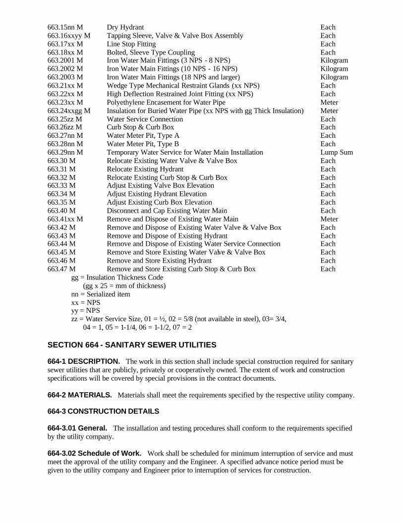
663.15nn M Dry Hydrant Each 663.16xxyy M Tapping Sleeve, Valve & Valve Box Assembly Each 663.17xx M Line Stop Fitting Each 663.18xx M Bolted, Sleeve Type Coupling Each 663.2001 M Iron Water Main Fittings (3 NPS - 8 NPS) Kilogram 663.2002 M Iron Water Main Fittings (10 NPS - 16 NPS) Kilogram 663.2003 M Iron Water Main Fittings (18 NPS and larger) Kilogram 663.21xx M Wedge Type Mechanical Restraint Glands (xx NPS) Each 663.22xx M High Deflection Restrained Joint Fitting (xx NPS) Each 663.23xx M Polyethylene Encasement for Water Pipe Meter 663.24xxgg M Insulation for Buried Water Pipe (xx NPS with gg Thick Insulation) Meter 663.25zz M Water Service Connection Each 663.26zz M Curb Stop & Curb Box Each 663.27nn M Water Meter Pit, Type A Each 663.28nn M Water Meter Pit, Type B Each 663.29nn M Temporary Water Service for Water Main Installation Lump Sum 663.30 M Relocate Existing Water Valve & Valve Box Each 663.31 M Relocate Existing Hydrant Each 663.32 M Relocate Existing Curb Stop & Curb Box Each 663.33 M Adjust Existing Valve Box Elevation Each 663.34 M Adjust Existing Hydrant Elevation Each 663.35 M Adjust Existing Curb Box Elevation Each 663.40 M Disconnect and Cap Existing Water Main Each 663.41xx M Remove and Dispose of Existing Water Main Meter 663.42 M Remove and Dispose of Existing Water Valve & Valve Box Each 663.43 M Remove and Dispose of Existing Hydrant Each 663.44 M Remove and Dispose of Existing Water Service Connection Each 663.45 M Remove and Store Existing Water Valve & Valve Box Each 663.46 M Remove and Store Existing Hydrant Each 663.47 M Remove and Store Existing Curb Stop & Curb Box Each gg = Insulation Thickness Code (gg x 25 = mm of thickness) nn = Serialized item xx = NPS yy = NPS zz = Water Service Size, 01 = ½, 02 = 5/8 (not available in steel), 03= 3/4, 04 = 1, 05 = 1-1/4, 06 = 1-1/2, 07 = 2 SECTION 664 - SANITARY SEWER UTILITIES 664-1 DESCRIPTION. The work in this section shall include special construction required for sanitary sewer utilities that are publicly, privately or cooperatively owned. The extent of work and construction specifications will be covered by special provisions in the contract documents. 664-2 MATERIALS. Materials shall meet the requirements specified by the respective utility company. 664-3 CONSTRUCTION DETAILS 664-3.01 General. The installation and testing procedures shall conform to the requirements specified by the utility company. 664-3.02 Schedule of Work. Work shall be scheduled for minimum interruption of service and must meet the approval of the utility company and the Engineer. A specified advance notice period must be given to the utility company and Engineer prior to interruption of services for construction.

664-3.03 Excavation. The requirements specified in Section 206, Trench, Culvert and Structure Excavation, shall apply. 664-3.04 Backfill. The requirements specified in §203-3.15, Fill and Backfill at Structures, Culverts, Pipes and Conduits and Direct Burial Cables, shall apply. 664-4 METHOD OF MEASUREMENT. As specified in the special specifications. 664-5 BASIS OF PAYMENT. As specified in the special specifications. SECTION 665 - WATERWAYS 665-1 DESCRIPTION. The work in this section shall include special construction required for the New York State Canal Corporation. The extent of work, material required, construction details, method of measurement and basis of payment will be covered by special provis ions in the contract documents. SECTION 666 (VACANT) SECTION 667 - LOCAL ROAD GRAVEL SURFACE, BASE, AND SUBBASE COURSES 667-1 DESCRIPTION. 667-1.01 General. The work consists of furnishing, placing and compacting gravel surface, base and subbase courses in conformity with the lines, grades, thicknesses and typical sections shown on the plans, or as determined by field conditions and ordered in writing by the municipality. 667-1.02 Material Types. Provide materials as specified by the following options. Type A. Surface quality material with a maximum particle size of 25 mm. Type B. Base quality material with a maximum particle size of 50 mm. Type C. Subbase quality material with a maximum particle size of 75 mm. 667-2 MATERIALS. 667-2.01 Test and Control Methods. All tests shall be performed by laboratories accredited under the AASHTO accreditation program. Materials tests and quality control methods pertaining to the work of this section will be performed in conformance with the procedures contained in the appropriate New York State Department of Transportation (NYSDOT) and/or American Association of State Highway and Transportation Officials (AASHTO) publications which are current on the date of advertisement of bids. 667-2.02 Materials Requirements. Provide materials for road gravel surface, base, and subbase courses that consist of Sand and Gravel, approved Blast Furnace Slag or Stone that meet the requirements contained herein. Provide materials well graded from coarse to fine, and free from organic or other deleterious materials. Any gravel material will be rejected if it is determined to contain any unsound or deleterious materials. A. Gradation. Perform sieve analysis in accordance with the AASHTO procedures T 27, T 88 or T 311. Report the following sieves for all tests: 75:m, 425:m, 6.3 mm, 12.5 mm, 19 mm, 25 mm, 37.5 mm, 50 mm, 75 mm. Provide material meeting the gradation limits from Table 667-1.

B. Soundness. Material for local road gravel surface, base, and subbase courses will be accepted on the basis of Magnesium sulfate Soundness Loss after four (4) cycles performed according to NYSDOT procedures and Table 667-2. C. Plasticity. Determine plasticity using either of the following methods: 1. Plasticity Index. The Plasticity Index of the material passing the #40 mesh sieve shall meet the values in Table 667-2. Determine plasticity using AASHTO tests T 89 and T 90. 2. Sand Equivalent. The sand equivalence of the granular material shall meet the values in Table 667-2. Determine sand equivalence using AASHTO test T 176. TABLE 667-1: PERCENT PASSING BY WEIGHT OF GRAVEL MATERIALS
Option Type Sieve (U.S. sieve)
A(Surface) B (Base) C (Subbase) 75 mm (3") 100 50 mm (2") 100 - 37.5 mm (1.5") 85-100 70-100 25 mm (1") 100 - - 19 mm (3/4") 85-100 - - 6.3 mm (1/4") 50-75 30-50 30-55 425 Fm (#40) 15-35 5-20 5-25 75 Fm (#200) 8-15 0-5 0-8 TABLE 667-2: TEST AND CONTROL LIMITS OF GRAVEL MATERIALS
Material Type Material Properties
A (Surface) B (Base) C (Subbase) Maximum Soundness loss (%) 20 20 25 Plasticity Index 2-9 0-5 0-8 Sand Equivalent >25 >40 >35 D. Elongated Particles. Not more than 30 percent, by weight, of the particles retained on a 12.5 mm sieve shall consist of flat or elongated particles. A flat or elongated particle is defined herein as one which has its greatest dimension more than 3 times its least dimension. Acceptance for this requirement will normally be based on a visual inspection. When the municipality elects to test for this requirement, material with a percentage greater than 30 will be rejected. E. Fractured Faces. When the municipality elects to test for this requirement, Type A material shall have at least two fractured faces on 50 percent of the stone particles larger than 12.5 mm or at least one fractured face on 75 percent of the particles larger than 12.5 mm. Type B material shall have at least one fractured face on 50 percent of the stone particles larger than 12.5 mm. 667-2.03 Stockpiling. Stockpile all material, except that material furnished under Type C will not be required to be stockpiled if the total project quantity is more than 500 tons, unless otherwise stated in the contract documents. Follow stockpile construction requirements, sampling, testing and acceptance/rejection procedures as stipulated by applicable NYSDOT procedures. 667-3 CONSTRUCTION DETAILS. 667-3.01 General. Use uniform gravel types and materials between the roadbed limits. 667-3.02 Placement.
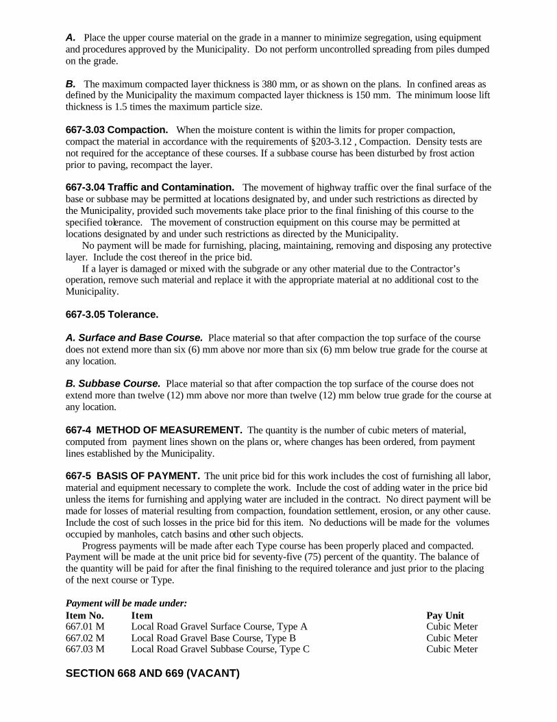
A. Place the upper course material on the grade in a manner to minimize segregation, using equipment and procedures approved by the Municipality. Do not perform uncontrolled spreading from piles dumped on the grade. B. The maximum compacted layer thickness is 380 mm, or as shown on the plans. In confined areas as defined by the Municipality the maximum compacted layer thickness is 150 mm. The minimum loose lift thickness is 1.5 times the maximum particle size. 667-3.03 Compaction. When the moisture content is within the limits for proper compaction, compact the material in accordance with the requirements of §203-3.12 , Compaction. Density tests are not required for the acceptance of these courses. If a subbase course has been disturbed by frost action prior to paving, recompact the layer. 667-3.04 Traffic and Contamination. The movement of highway traffic over the final surface of the base or subbase may be permitted at locations designated by, and under such restrictions as directed by the Municipality, provided such movements take place prior to the final finishing of this course to the specified tolerance. The movement of construction equipment on this course may be permitted at locations designated by and under such restrictions as directed by the Municipality. No payment will be made for furnishing, placing, maintaining, removing and disposing any protective layer. Include the cost thereof in the price bid. If a layer is damaged or mixed with the subgrade or any other material due to the Contractor’s operation, remove such material and replace it with the appropriate material at no additional cost to the Municipality. 667-3.05 Tolerance. A. Surface and Base Course. Place material so that after compaction the top surface of the course does not extend more than six (6) mm above nor more than six (6) mm below true grade for the course at any location. B. Subbase Course. Place material so that after compaction the top surface of the course does not extend more than twelve (12) mm above nor more than twelve (12) mm below true grade for the course at any location. 667-4 METHOD OF MEASUREMENT. The quantity is the number of cubic meters of material, computed from payment lines shown on the plans or, where changes has been ordered, from payment lines established by the Municipality. 667-5 BASIS OF PAYMENT. The unit price bid for this work includes the cost of furnishing all labor, material and equipment necessary to complete the work. Include the cost of adding water in the price bid unless the items for furnishing and applying water are included in the contract. No direct payment will be made for losses of material resulting from compaction, foundation settlement, erosion, or any other cause. Include the cost of such losses in the price bid for this item. No deductions will be made for the volumes occupied by manholes, catch basins and other such objects. Progress payments will be made after each Type course has been properly placed and compacted. Payment will be made at the unit price bid for seventy-five (75) percent of the quantity. The balance of the quantity will be paid for after the final finishing to the required tolerance and just prior to the placing of the next course or Type. Payment will be made under: Item No. Item Pay Unit 667.01 M Local Road Gravel Surface Course, Type A Cubic Meter 667.02 M Local Road Gravel Base Course, Type B Cubic Meter 667.03 M Local Road Gravel Subbase Course, Type C Cubic Meter SECTION 668 AND 669 (VACANT)
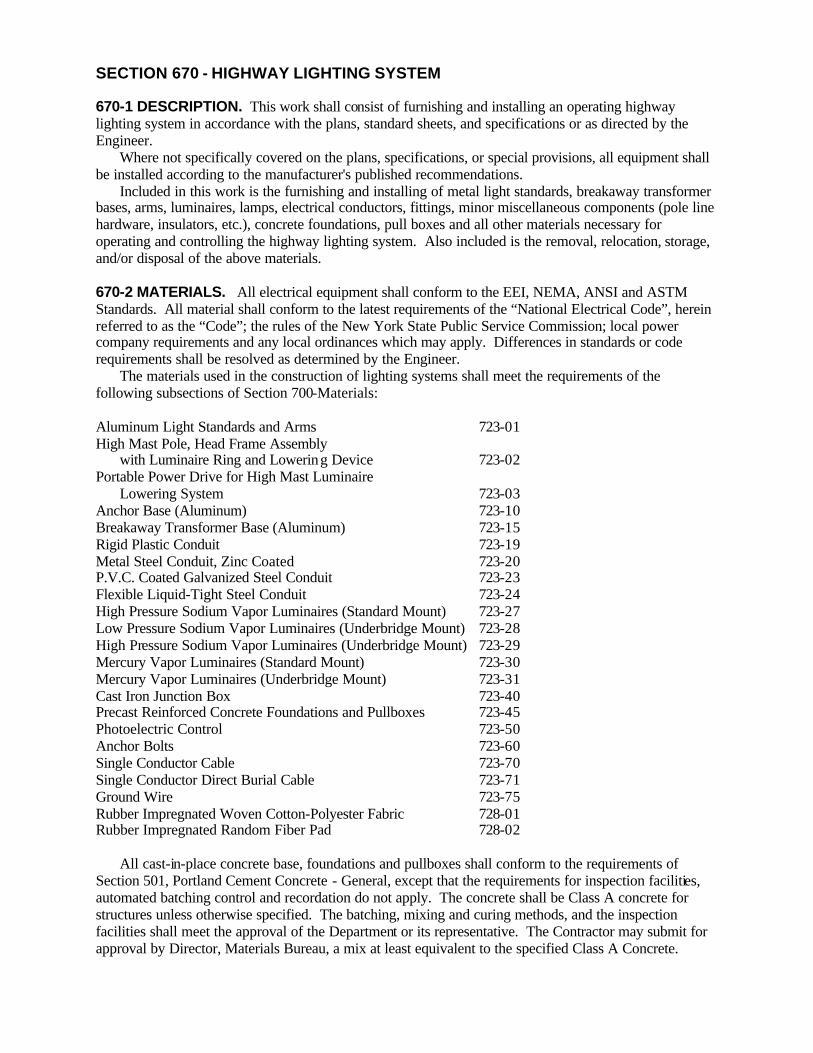
SECTION 670 - HIGHWAY LIGHTING SYSTEM 670-1 DESCRIPTION. This work shall consist of furnishing and installing an operating highway lighting system in accordance with the plans, standard sheets, and specifications or as directed by the Engineer. Where not specifically covered on the plans, specifications, or special provisions, all equipment shall be installed according to the manufacturer's published recommendations. Included in this work is the furnishing and installing of metal light standards, breakaway transformer bases, arms, luminaires, lamps, electrical conductors, fittings, minor miscellaneous components (pole line hardware, insulators, etc.), concrete foundations, pull boxes and all other materials necessary for operating and controlling the highway lighting system. Also included is the removal, relocation, storage, and/or disposal of the above materials. 670-2 MATERIALS. All electrical equipment shall conform to the EEI, NEMA, ANSI and ASTM Standards. All material shall conform to the latest requirements of the “National Electrical Code”, herein referred to as the “Code”; the rules of the New York State Public Service Commission; local power company requirements and any local ordinances which may apply. Differences in standards or code requirements shall be resolved as determined by the Engineer. The materials used in the construction of lighting systems shall meet the requirements of the following subsections of Section 700-Materials: Aluminum Light Standards and Arms 723-01 High Mast Pole, Head Frame Assembly
with Luminaire Ring and Lowering Device 723-02 Portable Power Drive for High Mast Luminaire Lowering System 723-03 Anchor Base (Aluminum) 723-10 Breakaway Transformer Base (Aluminum) 723-15 Rigid Plastic Conduit 723-19 Metal Steel Conduit, Zinc Coated 723-20 P.V.C. Coated Galvanized Steel Conduit 723-23 Flexible Liquid-Tight Steel Conduit 723-24 High Pressure Sodium Vapor Luminaires (Standard Mount) 723-27 Low Pressure Sodium Vapor Luminaires (Underbridge Mount) 723-28 High Pressure Sodium Vapor Luminaires (Underbridge Mount) 723-29 Mercury Vapor Luminaires (Standard Mount) 723-30 Mercury Vapor Luminaires (Underbridge Mount) 723-31 Cast Iron Junction Box 723-40 Precast Reinforced Concrete Foundations and Pullboxes 723-45 Photoelectric Control 723-50 Anchor Bolts 723-60 Single Conductor Cable 723-70 Single Conductor Direct Burial Cable 723-71 Ground Wire 723-75 Rubber Impregnated Woven Cotton-Polyester Fabric 728-01 Rubber Impregnated Random Fiber Pad 728-02 All cast-in-place concrete base, foundations and pullboxes shall conform to the requirements of Section 501, Portland Cement Concrete - General, except that the requirements for inspection facilities, automated batching control and recordation do not apply. The concrete shall be Class A concrete for structures unless otherwise specified. The batching, mixing and curing methods, and the inspection facilities shall meet the approval of the Department or its representative. The Contractor may submit for approval by Director, Materials Bureau, a mix at least equivalent to the specified Class A Concrete.
All precast concrete bases and foundations shall meet the requirements of §723-45 Precast Reinforced Concrete Foundations and Pullboxes. Anchor bolts encased in concrete foundations shall meet the requirements of §723-60, and shall be set by template. All concrete bases, foundations and pullboxes shall conform to the dimensions and details shown on the plans, standard sheets and specifications. Materials will be subject to inspection at any time during the contract. Failure of the Engineer to note faulty material or faulty installation during construction will not relieve the Contractor of responsib ility for removing or replacing such materials or redoing work which may fail to pass any of the Engineer's inspections of this work. 670-2.01 Conduit. Couplings, condulets, adaptors and bends shall be made from the same material as the conduit, unless otherwise indicated on the plans or directed by the Engineer. 670-2.02 Pullboxes. Pullboxes shall be cast-in-place or precast concrete units. Precast concrete units shown on the contract drawings for rectangular or circular pullboxes will be acceptable if they are of sufficient interior volume required under the pay item. If no drawings are given, the details shown on the Standard Sheet “Pullbox, Conduit and Ground Rod Installation Details” shall apply. 670-2.03 Luminaires. Luminaires shall be suitable for severe vibrations up to 3 G's, and lamp supports shall be provided if the lamp is horizontally mounted. 670-3 CONSTRUCTION DETAILS 670-3.01 Plans. The Contractor shall study the plans and details and use them as a guide in determining the location of the highway lighting equipment. Any discrepancies in the contract documents shall be resolved with the Engineer before any materials are ordered. Additionally, the manufacturer or supplier of the lighting equipment shall also use the plans to clearly label what each component part is or where it is to be installed. All installation shall conform to the latest EEI, NEMA, ANSI and ASTM standards. In addition workmanship shall conform to the latest requirements of the Code; the rules of the New York State Public Service Commission; local power company requirements and any local ordinances which may apply. Any work performed within the boundaries of New York City shall also be in accordance with the “General Specifications for Street Lighting Facilities” contained in the latest publication of “City of New York SPECIFICATIONS For Use With State of New York Department of Transportation Construction Contracts.” Differences in standards or code requirements shall be resolved as determined by the Engineer. 670-3.02 Shop Drawings. The Contractor shall submit six copies of the Manufacturer's Shop Drawings to the Engineer for approval. These drawings shall cover the following items and be submitted at least ten working days prior to the date the Contractor orders the light standards, breakaway transformer base, arms, precast concrete foundations and high mast poles, head assemblies and lowering devices. These items shall not be shipped to the job site until the shop drawings are approved. The shop drawings shall be neatly drawn and clearly legible. For luminaires and photoelectric controls catalog cuts may be submitted instead of shop drawings. 670-3.03 Excavation and Miscellaneous Work. All excavation shall conform to Section 206, Trench, Culvert and Structure Excavation. Included shall be the protection of workers and the public. Details of this protection shall conform to the requirements of 29CFR1926 Safety and Health Regulations for Construction (OSHA) and §107-05 Safety and Health Requirements Paragraph F. Cuts in roadways, sidewalk surfaces and driveways shall be done in a neat manner, so as to cause the least possible damage. Sawcutting will be required unless otherwise shown on the plans or directed by the Engineer. Excavation shall not be performed until immediately before installation of the conduit, direct burial cable or any other appurtenances. The excavated material will be placed in a location or locations approved by the Engineer. These locations shall be selected by the Contractor so as to cause the least inconvenience to vehicular and pedestrian traffic and to cause the minimum interference with the surface drainage.
All surplus excavated material shall be removed and disposed of by the Contractor as specified in §203-3.08, Disposal of Surplus Excavated Materials. Excavations shall be backfilled as specified in §203-3.15, Fill and Backfill at Structures, Culverts, Pipes, Conduits and Direct Burial Cables. After backfilling, the location shall be maintained to the satisfaction of the Engineer until permanent repairs are made. Pavement or structure courses shall be replaced as specified in §206-3.02, Replacement of Pavement Structure Courses, except that in concrete sidewalks, the complete sidewalk panel shall be removed and replaced. 670-3.04 Foundations. Locations of concrete foundations for light standards shown on the plans are approximate only and the exact location will be determined in the field. The Contractor has the option to use precast foundations in place of cast-in-place foundations for light standards. However, precast foundations shall not be allowed for high mast systems. All excavation necessary for constructing or installing a lamppost foundation shall be performed in conformance to §670-3.03. When cast-in-place concrete foundations can be constructed in undisturbed soil, as determined by the Engineer, the concrete shall be poured in direct contact with the earth. Forms shall not be used unless the excavation is oversize or where neat limits must be maintained. The top 0.3 to 0.5 meters shall be formed as specified on the plans or as directed by the Engineer. Care shall be taken to construct the tops of all foundations so they are level and true to line and grade. Anchor bolts shall be set by template, as ordered by the Engineer. When cast-in-place concrete foundations are to be constructed in soil that will not support a vertical cut, the foundations shall be formed. When forms are used, the foundations shall be backfilled and compacted allowing sufficient room for the compaction equipment selected. Where unstable soil is encountered, permanent support shall be used. This can include driving sheeting, augering in a pipe section, or any other method acceptable to the engineer. When precast foundations are used, the size of the precast foundation shall not be less than that shown on the plans or standard sheet for cast-in-place foundations. They are only to be used in conjunction with one of the following special excavation and backfill methods to insure foundation stability: Method A. The excavation shall allow a minimum clearance of 0.15 meters around the precast foundation to be backfilled with concrete meeting the requirements of §501-2.02, Class A. For backfill purposes, small construction mixers will be permitted. Method B. The excavation shall allow a minimum clearance around the precast unit compatible with the compaction equipment used. The clear area shall be backfilled with Select Granular Fill in accordance with §203-2.02 of the Standard Specifications, and compacted in accordance with §203-3.15. Method A or Method B can be used in undisturbed areas. Only Method B is to be used in disturbed areas. 670-3.05 Grounding. A 3 meter by 16 millimeter diameter, copperclad ground rod shall be driven near each foundation, maintaining at least 600 mm of cover, or through selected pullboxes where metal conduit is used. The ground rod shall be electrically connected to the base of the pole with a No. 6 soft drawn bare stranded copper ground wire. A copperclad groundwire clamp shall be used to attach the ground wire to the ground rod. Where a 3 meter ground rod cannot be driven, or is insufficient to provide adequate grounding (see §670-3.16), alternate methods shall be used as shown on the plans or ordered by the Engineer. Such alternate methods can include changing the ground rod length or location, or connecting the ground wire to some other grounded object. 670-3.06 Light Standards, Breakaway Transformer Bases and Arms. Each metal light standard shall be set vertically (within 1E of plumb) on a foundation or anchorage, employing approved shims when necessary, either with or without a transformer base as shown on the plans or in the proposal. The transformer base, or the anchor base when a transformer base is not used, shall be securely bolted to the anchorage by the anchor bolts previously set.

The individual light standards shall be identified as required by the responsible maintenance agency and as shown on the plans. Each arm shall be mounted on the shaft so the luminaire will be at the proper mounting height as shown on the plans. The mounting height shall be measured from the center of the light source to the pavement. The arms shall be in a plane perpendicular to the roadway. The Contractor, in conjunction with the Engineer, shall determine the necessary elevation data for fabricating the light standard with the correct mounting height. A Number 8 Gauge galvanized steel or 6 millimeter nylon rope drag line shall be furnished and installed running from the terminal strip area in the luminaire to the anchor base or box where the power distribution cable is or will be installed. This drag line shall be securely anchored at each end, and removed only after the cables are installed. The protective wrapping shall not be removed from any of the shafts or arms until the Engineer instructs the Contractor to do so. 670-3.07 Conduit. Underground conduit shall be either zinc coated metal steel conduit, PVC coated galvanized steel, rigid plastic, or flexible liquid-tight steel conduit, as indicated on the plans, and shall be carefully laid in trenches prepared to receive them. Unless indicated otherwise, conduits in exposed areas, when attached to the outside of structures, such as underdeck installations, shall be PVC coated galvanized steel conduit installed as shown on the plans or in a manner approved by the Engineer. Hot dipped, galvanized or non-rusting alloy steel clamps shall be provided to support the conduit at intervals not exceeding 1 m or as directed by the Engineer. Underground conduit installations shall have a minimum cover of 0.45 meters except under roadways, where the minimum cover shall be 0.6 meters. The conduit shall be laid on a uniform grade to allow any condensation to drain to pull boxes or “T” drains, as detailed on the Standard Sheet “Pullbox, Conduit and Ground Rod Installation Details”. Where uniform grades cannot be maintained, “T” drains shall be installed where directed by the Engineer. Conduit shall be backfilled in accordance with §203-3.15 Fill and Backfill at Structures, Culverts, Pipes, Conduits, and Direct Burial Cables. However, in rock excavations, a bedding of selected backfill must be placed and tamped before laying the conduit. All bends in the conduit shall be made without kinking, flattening or appreciably reducing the internal diameter of the conduit. A hydraulic or power pipe bender shall be employed, unless a template is used, for all bends in steel conduit. No bends will be accepted for exposed conduit which shows any evidence of destruction of the protective coating. Where conduits terminate at pullboxes, the Contractor shall break into the pullbox and seal, usually with mortar, the remainder of the hole(s) in a manner acceptable to the Engineer. Sealed bonding bushings shall be provided at each conduit outlet in boxes. Bushing caps, to prevent entry of dirt and refuse prior to pulling cables, shall be placed on all conduit ends. Outlet boxes with conduits properly connected shall be accurately located according to the plans and securely fastened. All conduits installed shall be tested for clear bore and correct installation by the Contractor using a ball mandrel, brush and snake before the installation will be accepted. Two short wire brushes shall be included in the mandrel assembly. Snaking of conduits shall be done by the Contractor in the presence of the Engineer. Any conduit which rejects the mandrel shall be cleared and the Contractor shall bear all costs to replace defective conduit and restore surface to original condition. Numbers or letters shall be assigned to the various conduit runs, and as they test clear, they shall be identified by a brass tag, no less than 31 mm in diameter, attached by means of No. 20 AWG brass wire. All conduit terminations in pole bases or pull boxes shall be tagged. As the conduit runs test clear, a record shall be kept under the heading of “Empty Conduits Tested, Left Clear, Tagged and Capped,” showing conduit designation, diameter, location, date tested and by whom. When completed, this record shall be signed by the Electrical Inspector and submitted in triplicate for approval. This record shall be entered on the Record Drawings. All empty conduit and duct openings after test, shall be capped or plugged by the Contractor as directed. After a conduit is properly installed and cleaned, the Contractor shall furnish and install in each conduit run a No. 10 AWG galvanized steel drag line or nylon or polypropylene rope, with a tensile strength of at least 2222 newtons, leaving at least 1 meter of extra line in each pull box, transformer base, or other terminus. If cable is not pulled through the conduit within thirty days, the steel drag shall be grounded to a suitable grounding device at each end of the circuit. All metallic connections shall be tight to assure continuity of ground bondings.

Conduit shall be placed under existing pavement by approved jacking or boring methods and as directed by the Engineer. The jacking or boring pit shall be located beyond the outside shoulder keeping at least 0.6 meters clear of the edge of shoulder. Jacking pits will not be permitted in the median, but receiving pits may be dug in grass medians after the jacking is completed if permitted on the plans or by the Engineer. 670-3.08 Pullboxes. Cast-in-place or precast concrete pullboxes shall be constructed at the locations and to the dimensions shown in the plans, standard sheets, specifications, or proposal. Excavations for pullboxes shall be performed in accordance with the requirements of §206-3, Construction Details for Trench, Culvert and Structure Excavation, and included in this item. Frames and covers shall be furnished and placed on each pullbox. They shall be placed true to line and grade and make full and even bearing on the pullbox. The frames and covers shall be of the design and detail shown in the plans, standard sheets, specifications or proposal. Frames and covers which do not fit together properly, are warped or rock, will be rejected by the Engineer. Any material rejected by the Engineer, will be removed from the site by the Contractor. No pullbox shall be backfilled until all cement concrete has sufficiently hardened and forms, if any, have been removed. The requirements of §203-3.15, Fill and Backfill at Structures, Culverts, Pipes, Conduits and Direct Burial Cables, shall apply. 670-3.09 Junction Boxes. Cast iron junction boxes shall be installed at the locations shown on the plans. For surface mounting, the boxes shall be securely bolted to brackets as detailed on the plans. For installation where boxes are embedded in cement concrete, the boxes shall be set with the covers flush with the surface. All hardware used in conjunction with mounting of these boxes shall be rust and corrosion resistant. 670-3.10 Luminaires. Luminaires of the type and wattage specified, complete with all components shall be installed where shown on the plans standard sheets, or proposal or where directed by the Engineer. All necessary field adjustments required to achieve the specified light distribution shall be performed as directed by the Engineer. A. Standard Mounting. Luminaires shall be installed on light standard mast arms with the vertical axis perpendicular to the roadway and the longitudinal axis parallel to the roadway centerline. The luminaires shall be installed, though not necessarily powered, immediately after the mast arms are connected to the shaft. Otherwise, vibration dampeners shall be used until the luminaires are installed. B. Underbridge Mounting. Luminaires of the type and wattage specified shall be installed on wall mounts or outlet box studs. Self-contained underbridge luminaires complete with all specified ballasts, and any other appurtenances necessary shall be installed according to manufacturers written instructions, as shown on the plans, as specified in the proposal or as directed by the Engineer. 670-3.11 Photoelectric Control. Photoelectric controls shall be installed at the locations shown on the plans, preferably facing north, and properly adjusted to energize the luminaires at the specified illumination levels. 670-3.12 Single Conductor Cable and Single Conductor Direct Burial Cable. Wire installation shall not start until raceways and boxes have been cleared of all foreign matter and all other operations of the work which are likely to damage the conductors have been completed. The National Electric Code Rules shall be observed regarding installation of wire and cable. Unless otherwise specified, splices will be permitted only in pullboxes, junction boxes, utility manholes, luminaires, transformer bases, and lamppost hand holes. All conductor runs between units of equipment shall be without splices. Conductors in control cabinets shall not be spliced.

All splices shall be capable of satisfactory operation under continuous submersion in water. Multiple conductors shall be spliced and insulated to provide a watertight joint and to prevent absorption of moisture by the conductors. Moisture shall be excluded from the joint during the splicing operation and the work shall be done in dry weather or under shelter. Perspiration from the splicer's hand should be wiped off with dry material. All materials and tools involved in the splicing process shall be kept dry. One of the following methods shall be used for making a watertight and electrically insulated splice: Method No. 1. The outer covering and insulation shall be removed from each conductor for a minimum length necessary for the use of a pressure release crimping tool. The conductor ends shall be bared and jointed with a seamless, solderless type sleeve connector of the same AWG size as the conductor being spliced, using a pressure release crimping tool designed for the size connector being used. After crimping the sleeve connector shall maintain proper contact with both conductors around the circumferences of the splice and along the length of the sleeve. The portion of each conductor where insulation has been removed, and the sleeve connector, shall be reinsulated using a coat of fast drying sealing agent of electrical grade, wrapped tightly with overlapping layers of rubber tape, a second coat of the sealing agent applied, and then wrapped tightly with overlapping layers of polyvinylchloride tape. The sealing agent and tape shall extend at least 25 mm onto the undisturbed insulation of each conductor. Sufficient layers of tape shall be applied to equal 1.5 times the thickness of the original insulation. Rejacketing the cable shall be accomplished in a similar manner as described above except that the sealing agent and tape shall extend at least 0.1 meters onto the undisturbed outer covering of each cable. Individual splices in each conductor shall be staggered to minimize the outside diameter of the splice. Method No. 2. All of the requirements for splicing, specified in Method No. 1, shall apply, except that the completed splice including sleeve connector and the portion of each conductor where the insulation has been removed, shall be reinsulated and the conductor rejacketed by using an acceptable mold poured full with a two component dielectric epoxy resin. The resin shall not require external heating to produce satisfactory pouring consistency. 670-3.13 Ground Cable. Ground cable shall be installed where and as detailed on the plans or as directed by the Engineer. 670-3.14 Regulations. All work shall be done in accordance with latest edition of the national electrical safety codes, rules and regulations of the State authorities having jurisdiction over such work, and regulations of the utility companies where the work is being installed. Where differences or discrepancies occur, the most stringent requirements shall apply. 670-3.15 Prosecution of Work. All work shall be done by qualified and experienced mechanics of each labor class, as determined by the Engineer. All work shall be inspected and approved by the Engineer before concealment. 670-3.16 Tests. The Contractor shall conduct all tests, in the presence of the Engineer. The equipment required for each test shall be supplied by the Contractor, along with the equipment manufacturer's written instructions describing how to perform the test. The following tests shall be performed by the Contractor, at the time directed by the Engineer, prior to acceptance of the work: A. Insulation Test. Each circuit with associated ballasts and protective devices shall be insulation tested using an insulation tester connected according to manufacturers instructions. A polarization index shall be computed by dividing a ten minute reading by a one minute reading. The polarization index shall be greater than four (4) for acceptance of new circuits, and greater than two (2) for acceptance of existing circuits. The lighting system shall be properly grounded and disconnected while this test is taking place. B. Ground Test. A ground test shall be performed by the Contractor using an earth tester with resolution to at least a tenth of an ohm. The test shall be performed, and the results interpreted, according
to manufacturer's instructions. Readings of five ohms or less will be required for acceptance. Additional grounding methods satisfactory to the Engineer may be necessary until the installation can pass the ground test. C. Functional Test. After satisfactory completion of all other tests, a functional test shall be performed consisting of not less than ten consecutive days of satisfactory operation. If unsatisfactory performance of any component of the lighting system is discovered during this time, the condition shall be corrected and the Engineer may require the test repeated until ten days of continuous satisfactory operation is obtained. Temporary shut downs caused by power interruption or vehicle impact shall not constitute discontinuity of the functional test. 670-3.17 Coordination with Utility Company. The Contractor shall be responsible for all coordination with and between the utility company. The Contractor shall make all necessary arrangements with the utility company for the required electrical services necessary for the energizing of a temporary lighting installation and barricade lighting. The Contractor shall comply with the utility company regulations. The utility company will connect and disconnect the power as required. When an entry into a service manhole or attachment to any utility company pole is required, the Contractor shall notify the utility company sufficiently in advance, and under no condition shall the Contractor enter any utility company owned manhole or place an attachment to a utility company owned pole without an agreement with the utility company. The service points shown on the plans are approximate only and the Contractor shall determine the exact location from the serving utility company. When called for in the contract documents the Contractor shall make arrangements with the local utility company to complete the service connections. 670-3.18 Removal and Disposal, or Storage, of Lighting Equipment. Existing lighting equipment designated for storage shall be carefully removed from their present locations by disconnecting the conductors, unbolting the mast arm(s) and luminaire(s) and detaching the shaft (and transformer base) from the anchor bolts. The work shall be performed in a manner acceptable to the Engineer. Component parts designated for storage shall be neatly stored and protected during storage at locations and in a manner as approved by the Engineer. Standards designated for removal and disposal shall be disposed of by the contractor in a manner approved by the Engineer within the directed time period after removal from their original location. The concrete lamppost foundations shall be cut free of the attached trenched conduits and shall be removed by the Contractor from the job site. The hole resulting from removing the foundation shall be filled with an approved material and compacted as directed by the Engineer. 670-3.19 Relocation of Lighting Equipment. Lighting equipment designated for relocation shall be detached and stored as per §670-3.18, reinstalled and successfully retested at the new location. The complete relocation shall take place in one work shift unless otherwise shown on the plans or ordered by the Engineer. Where bracket arms and luminaires are to be relocated onto other utility poles, the down leads shall also be relocated, or replaced in kind if necessary, AOBE. (Down leads include small sections of conduit or wood molding, wires and fuses connecting the secondary power supply line to the luminaire.) The bracket arm shall be attached to the pole with hardware similar to existing. The Contractor shall also relocate the epoxied strap used where the bracket arm is located above telephone lines. Any part of the bracket arm, luminaire, or down lead damaged during removal or reinstallation shall be replaced or repaired to the satisfaction of the Engineer. 670-3.20 High Mast Pole, Head Frame Assembly and Lowering System. The high mast steel pole, head frame assembly and lowering system shall be installed in accordance with the manufacturer's recommendations, or as directed by the Engineer. With each installation a Manufacturer's instructional manual shall be furnished in each pole base. This manual shall include, but not be limited to the following details: 1. Raise and lower assembly instructions
2. Operating instructions 3. Maintenance instructions 4. Attachments Additionally, the luminaire ring with all luminaires installed shall be lowered and raised five (5) times, at least twice in the coldest part of the winter and twice in the hottest part of the summer, if possible, to test functionability. These test dates shall be determined by the Engineer. Failure to lower or rise properly will be means for rejection of the assembly. 670-3.21 Portable Power Drive for High Mast Luminaire Lowering System. The portable power drive shall be used to raise and lower the luminaire ring as described above, and be delivered in good condition to the location shown on the plans upon acceptance of the high mast system. 670-4 METHOD OF MEASUREMENT 670-4.01 Foundations. Lighting standard foundations will be measured as the number of complete units installed in accordance with the plans, specifications or as directed by the Engineer. 670-4.02 Light Standards. Light standards will be measured as each standard of the type specified, complete, in place, in accordance with plans, specifications or as directed by the Engineer. 670-4.03 Arms. Arms of the type and length specified will be measured by the number of units furnished and installed on the respective light standards (or wood poles) according to the plans, specifications or as directed by the Engineer. 670-4.04 Breakaway Transformer Base. Breakaway transformer bases will be measured as the number furnished and installed in accordance with the plans, specifications or as directed by the Engineer. 670-4.05 Conduit. Conduit will be measured by the linear meters along the axis of the conduit, of the type and size specified, installed according to the plans, proposal, or as directed by the Engineer. Measurement shall include all couplings, condulets, adaptors and bends. 670-4.06 Pullboxes. Pullboxes, including frames and covers, will be measured as the number furnished and installed in accordance with the plans, specifications or as directed by the Engineer. 670-4.07 Junction Box. Cast iron junction boxes will be measured as the number of each size furnished and installed in accordance with the plans, specifications or as directed by the Engineer. 670-4.08 Luminaires. Luminaires of the type and wattage specified will be measured by the number of units furnished and installed according to the plans, specifications or as directed by the Engineer. 670-4.09 Photoelectric Controls. Photoelectric controls will be measured as each control furnished and installed in accordance with the plans, specifications or as directed by the Engineer. 670-4.10 Single Conductor Cable and Direct Burial Cable. Single Conductor Cable wire will be measured for payment by the number of linear meters of single conductor of each size actually installed in accordance with the plans and specifications or as directed by the Engineer. 670-4.11 Ground Wire. Ground wire will be measured for payment by the number of linear meters of ground wire installed in accordance with the plans and specifications or as directed by the Engineer. 670-4.12 Removal of Lighting Equipment. The removal of lighting equipment will be measured by the number of light standards (including bracket arms and luminaires), or foundations, removed from the site and stored or disposed of as ordered by the Engineer.

670-4.13 Relocation of Lighting Equipment. The relocation of lighting equipment will be measured by the number of specified units removed and reinstalled at the new location. 670-4.14 High Mast Pole, Head Frame and Lowering Assembly. High mast steel pole, head frame assembly and lowering system will be measured by the number of complete units furnished and installed in accordance with the contact documents. 670-4.15 Portable Power Drive for High Mast Luminaire Lowering System. The portable power drive for high mast luminaire lowering system will be measured by the number of complete units delivered. 670-5 BASIS OF PAYMENT 670-5.01 General. The Contractor shall pay all fees and expenses for testing, service connections, licenses, electrical energy and any other cost he may incur in constructing the highway illumination system, except that the cost of electrical energy used for public benefit prior to the completion of the contract will be borne by the State, when such operation is directed by the Engineer in writing. The cost of all minor miscellaneous components shall be included in the price bid for the various lighting items. 670-5.02 Foundations. The unit price for each lighting standard foundation shall include the cost of all labor and materials necessary to complete the work, including conduit elbows, grounding system, anchor bolts, all appurtenances, excavation, special fill, and any protective system(s) required to ensure the safety of the workers and the public. 670-5.03 Light Standards. The unit bid for each light standard shall include the cost of all labor and other materials necessary to complete the work. 670-5.04 Arms. The unit price bid for each arm of the type and length specified shall include the cost of the arm, appropriate down leads and all labor and other materials necessary to install it on the designated light standard or wood pole shown on the plans. 670-5.05 Breakaway Transformer Bases. The unit price bid for each breakaway transformer base shall include the cost of the breakaway transformer base and all labor and other materials necessary to install it where shown on the plans. 670-5.06 Conduit. The unit price bid per linear meter shall include the conduit and all labor and other materials necessary to complete the work, including couplings, condulets, adaptors or bends. Excavation and backfill for conduit shall be paid for separately under the item for Conduit Excavation and Backfill or as indicated. 670-5.07 Pullbox. The unit price bid for each pullbox shall include the cost of all excavation, backfill, frames, covers, labor, equipment, and other materials necessary to complete the work. 670-5.08 Junction Box. The unit price bid per each junction box shall include the cost of furnishing and installing cast iron junction boxes, and all labor, equipment and any other material necessary to complete the work. 670-5.09 Luminaires A. Standard Mount. The unit price bid for each standard mount luminaire shall include the cost of the luminaire of the type specified, labor and other material necessary to complete the work. B. Underbridge Mount. The unit price bid for each underbridge luminaire shall include the cost of the underbridge luminaire of the type specified, complete with mounting hardware, and all labor and other materials necessary to complete the work.

670-5.10 Photoelectric Controls. The unit price bid for each control shall include the cost of all labor, equipment and any materials necessary to complete the work. 670-5.11 Single Conductor Cable and Direct Burial Cable. The unit price bid per linear meter shall include the cost of furnishing all labor, materials, and equipment to satisfactorily complete the work. Cable from the pole base to the luminaire, or from the overhead power source to the luminaire, will be included in the light standard item or bracket arm item. 670-5.12 Ground Wire. The unit price bid per linear meter shall include the cost of furnishing all labor, materials, and equipment to satisfactorily complete the work. 670-5.13 Remove and Store Lighting Equipment. The unit price bid for removing and storing lighting equipment shall include the cost of all labor, materials and equipment necessary to complete the work. Removing concrete foundations will be paid for under its appropriate item. 670-5.14 Remove and Dispose of Lighting Equipment. The unit price bid for removing and disposing lighting equipment shall include the cost of all labor, materials and equipment necessary to complete the work. Removing concrete foundations will be paid for under its appropriate item. 670-5.15 Relocate Lighting Equipment. The unit price bid for relocating the lighting equipment shall include the cost of all labor, materials and equipment necessary to complete the work. Installing new concrete foundations will be paid for under their appropriate items. New conductors and conduit, where necessary, will also be paid for separately. 670-5.16 High Mast Pole, Head Frame Assembly, and Lowering System. The price bid shall include the furnishing of all labor, materials, and equipment necessary to complete the work. The luminaires will be paid for separately. 670-5.17 Portable Power Drive for High Mast Luminaire Lowering System. The price bid shall include the entire power drive assembly, and winch if necessary, delivered to the location indicated on the plans or directed by the Engineer. Payment will be made under: Item No. Item Pay Unit 670.01XX M Foundation for Light Standards XX = Foundation Length in meters and tenths (1.2, 1.8, etc.) Each 670.11XX M Aluminum Light Standards for Single Member or Truss Arm(s) XX =Mounting Height in whole meters (08, 09, 11, 13, 14, 16) Each 670.12XX M Aluminum Single Member Bracket Arm XX = Arm Length in meters and tenths (1.2, 1.8, 2.4, 3.0) Each 670.13XX M Aluminum Trussed Arm XX = Arm Length in meters and tenths (Errata“3.0,”3.6, 4.5, 5.4, 6.0) Each 670.14XX M Aluminum Bracket Arm, Wood Pole Mounted XX = Arm Length in meters and tenths (1.8, 3.6, 4.5, 5.4) Each 670.15XX M Aluminum Light Standard for Single Davit Arm XX = Mounting height in whole meters (09, 11, Errata“12,” 13, 14, 16) Each 670.16XX M Aluminum Light Standard for Double Davit Arms XX = Mounting height in whole meters (09, 11, 13, 14, 16) Each 670.17XX M Aluminum Davit Arm XX = Arm Length in meters and tenths (1.8, 3.6, 4.5, 5.4, 6.0) Each 670.18XXZZ M High Mast Pole, Head Frame Assembly with Luminaire Ring and Lowering Device XX = Height of pole in whole meters (30, 36, 45) ZZ = Number of luminaire tenons (04, Errata“05,” 06, 08, 10, 12) Each 670.1801 M Portable Power Drive for High Mast Luminaire Lowering System Each 670.19 M Breakaway Transformer Base (Aluminum) Each
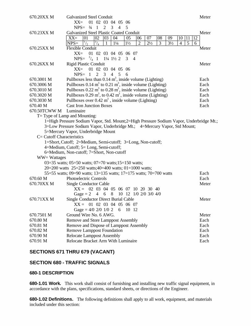
670.20XX M Galvanized Steel Conduit Meter XX= 01 02 03 04 05 06 NPS= ¾ 1 2 3 4 5 670.23XX M Galvanized Steel Plastic Coated Conduit Meter
XX= 01 02 03 04 05 06 07 08 09 10 11 12 NPS= 1/2 3/4 1 1¼ 1½ 2 2½ 3 3½ 4 5 6
670.25XX M Flexible Conduit Meter XX= 01 02 03 04 05 06 07 NPS= 3/4 1 1¼ 1½ 2 3 4 670.26XX M Rigid Plastic Conduit Meter XX= 01 02 03 04 05 06 NPS= 1 2 3 4 5 6 670.3001 M Pullboxes less than 0.14 m3, inside volume (Lighting) Each 670.3006 M Pullboxes 0.14 m3 to 0.21 m3, inside volume (Lighting) Each 670.3010 M Pullboxes 0.22 m3 to 0.28 m3, inside volume (Lighting) Each 670.3020 M Pullboxes 0.29 m3, to 0.42 m3 , inside volume (Lighting) Each 670.3030 M Pullboxes over 0.42 m3 , inside volume (Lighting) Each 670.40 M Cast Iron Junction Boxes Each 670.50TCWW M Luminaire T= Type of Lamp and Mounting: 1=High Pressure Sodium Vapor, Std. Mount;2=High Pressure Sodium Vapor, Underbridge Mt.; 3=Low Pressure Sodium Vapor, Underbridge Mt.; 4=Mercury Vapor, Std Mount; 5=Mercury Vapor, Underbridge Mount C= Cutoff Characteristics 1=Short, Cutoff; 2=Medium, Semi-cutoff; 3=Long, Non-cutoff; 4=Medium, Cutoff; 5= Long, Semi-cutoff; 6=Medium, Non-cutoff; 7=Short, Non-cutoff WW= Wattages 03=35 watts; 05=50 watts; 07=70 watts;15=150 watts; 20=200 watts 25=250 watts;40=400 watts; 01=1000 watts; 55=55 watts; 09=90 watts; 13=135 watts; 17=175 watts; 70=700 watts Each 670.60 M Photoelectric Controls Each 670.70XX M Single Conductor Cable Meter XX = 02 03 04 05 06 07 10 20 30 40 Gage = 2 4 6 8 10 12 1/0 2/0 3/0 4/0 670.71XX M Single Conductor Direct Burial Cable Meter XX = 01 02 03 04 05 06 07 Gage = 4/0 2/0 1/0 2 6 10 12 670.7501 M Ground Wire No. 6 AWG. Meter 670.80 M Remove and Store Lamppost Assembly Each 670.81 M Remove and Dispose of Lamppost Assembly Each 670.82 M Remove Lamppost Foundation Each 670.90 M Relocate Lamppost Assembly Each 670.91 M Relocate Bracket Arm With Luminaire Each SECTIONS 671 THRU 679 (VACANT) SECTION 680 - TRAFFIC SIGNALS 680-1 DESCRIPTION 680-1.01 Work. This work shall consist of furnishing and installing new traffic signal equipment, in accordance with the plans, specifications, standard sheets, or directions of the Engineer. 680-1.02 Definitions. The following definitions shall apply to all work, equipment, and materials included under this section:

1. Actuation - The operation of any type of detector. 2. Controller - That part of a controller assembly which performs the basic timing and logic functions. 3. Controller Assembly - The complete assembly for controlling the operation of a traffic signal, consisting of a controller together with all auxiliary equipment, housed in a weatherproof cabinet or cabinets. 4. Cycle Length - The time in seconds required for one complete signal cycle. 5. Detector - A device for indicating the passage or presence of vehicles or pedestrians. 6. Inductance Loop Detector - A detector consisting of a wire loop embedded in the roadway surface connected to an electronic device that is capable of sensing the passage or presence of either moving or stationary vehicles by a change in the electrical inductance characteristics of the wire loop. 7. Interval - That part or parts of a signal cycle during which signal indications do not change. 8. Phase - That part of a signal cycle allocated to any traffic movement receiving the right of way or to any combination of traffic movement receiving the right of way simultaneously during one or more intervals. Each phase shall consist of at least one green interval and one yellow clearance interval. 9. Signal Cycle - A complete sequence of signal indications. 10. Signal Face - That part of a signal head provided for controlling traffic in a single direction and consisting of one or more signal sections. Turning indications may be included in a signal face. 11. Signal Head - An assembly containing one or more signal faces which may be designated accordingly as one-way, two-way, etc. 12. Signal Indication - The illumination of a traffic signal lens or equivalent device, or a combination of several lenses or equivalent devices at the same time. 13. Signal Section - A complete unit for illuminating a lens consisting of a housing, lens, reflector, lamp receptacle, and lamp. 14. Type I Traffic Signal Section. A Type I Traffic Signal Section is a standard or polycarbonate traffic signal section without reflector, reflector ring, lens, and lamp receptacle. 15. Type I Pedestrian Signal Section. A Type I Pedestrian Signal Section is a standard or polycarbonate pedestrian signal section without reflector, lens, and lamp receptacle. 680-2 MATERIALS 680-2.01 Traffic Signal Equipment. The specific components used in the construction of new traffic signal systems shall meet the requirements of the following subsections included under section 700, MATERIALS DETAILS: Bar Reinforcement, Grade 420 709-01 Iron Castings 715-05 Breakaway Transformer Base 723-15.01 Rigid Plastic Conduit 723-19 Metal Steel Conduit, Zinc Coated 723-20 P.V.C. Coated Galvanized Steel Conduit 723-23 Flexible Liquid-Tight Steel Conduit 723-24 Cast Iron Junction Boxes 723-40 Precast Reinforced Concrete Pullboxes 723-45 Signal Cable 724-01 Span Wire 724-02 Traffic Signal Poles 724-03 Traffic Signal Heads 724-04 Shielded Communication Cable 724-08 Signal Cable with Integral Messenger 724-09 Shielded Communication Cable with Integral Messenger 724-10 Fire Pre-emption Tell Tale Light 724-15 Inductance Loop Wire 724-20 Shielded Lead-in Cable 724-21 Roadway Loop Embedding Sealer 724-22 Pedestrian Push Button and Sign 724-23

Fiberoptic Pedestrian Signal Heads 724-04 Fiberoptic Dual Indication Arrow 724-04 Strobing Signal Indication 724-04 LED Traffic Signal Modules 724-04 LED Pedestrian Signal Modules 724-04 680-2.02 Concrete. All cast-in-place pullboxes, signal pole foundations and controller cabinet bases shall meet the requirements of Class A concrete in section 501, Portland Cement Concrete General, except that the requirements for inspection facilities, automated batching controls and recordation do not apply. The batching, mixing and curing methods and the inspection facilities shall meet the approval of the Department or its representative. The Contractor may submit, for approval by Director, Materials Bureau, a mix at least equivalent to the specified Class A Concrete. All precast concrete pullboxes, signal pole foundations and controller cabinet bases shall meet the requirements of §723-45 Precast Reinforced Concrete Pullboxes. 680-2.03 Messenger Wire. Messenger wire shall meet the requirements of §724-02 Span Wire. 680-2.04 Guy Wire. Guy wire shall meet the requirements of §724-02 Span Wire. 680-2.05 Pullbox Frames and Covers. Frames and covers shall meet the requirements of §715-05 Iron Castings. 680-3 CONSTRUCTION DETAILS 680-3.01 Equipment List and Drawings. Unless otherwise waived, the Contractor shall submit to the Regional Director within 30 days following the award of contract, detailed specifications, catalog cuts, parts list, instruction sheets, and shop drawings of equipment and materials which he proposes to install. 680-3.02 (Vacant). 680-3.03 Negotiations with Utility Company. The Contractor shall be responsible for all negotiations involving utility companies. The Contractor shall comply with utility company regulations. When a entry into a service manhole or attachment to any utility company pole is required, the Contractor shall notify the utility company sufficiently in advance. Entry into a service manhole or attachment to any pole shall not be made without the presence of a utility company representative if the utility company so requires. The service points shown on the plans are approximate only and the Contractor shall determine the exact location from the serving utility company. The Contractor shall make arrangements with the local utility company to complete the service connection. 680-3.04 Underground Facilities. The Contractor shall locate all existing underground facilities in accordance with the provisions of Industrial Code Rule 753. It shall be the Contractors responsibility to satisfy himself as to existing conditions and to protect and support in a suitable manner all underground facilities encountered during the trenching and excavating operations. The Contractor shall repair any damage to these lines caused by his operations, and if the nature of the damage is such as to endanger the operations of these services and utilities and the necessary repairs are not immediately made by the Contractor, the work may be performed by the State or other Contractor and the cost thereof charged against the Contractor. 680-3.05 Test Holes. Prior to excavating for pole placement and after locating all existing underground facilities, the Contractor shall dig a test hole or holes at the proposed location of each pole. If obstructions are encountered the Contractor shall properly backfill the test hole and move to a new location as directed by the Engineer.

680-3.06 Work Sites. The Contractor shall perform all work within the work site in a workmanlike manner and in accordance with U.S. Department of Labor's Occupational Safety and Health Standards. The sites of the work and adjacent premises shall be kept as free from material, debris and rubbish as is practicable. All such material or debris that accumulates during the work shall be removed by the Contractor as the work progresses. Neither the materials excavated, nor the materials used, shall be placed so as to prevent access to any fire hydrants, water valves, manholes, police call boxes or fire alarm boxes. 680-3.07 Schedule of Work. The Contractor shall notify the local power company at least 72 hours (or as required by the company) in advance of the time that the individual installation is complete and ready for operation in order that taps may be made by the power company to distribution lines. Upon completion of a signal installation the signal may be placed in service prior to the completion of other installations or the signal head may be covered. The Contractor shall place the signal in operation or cover the head as directed by the Engineer. When the traffic signal is placed in operation, it shall be operated in accordance with timing schedules to be supplied by the Department. 680-3.08 Contractor Responsibility with Utilities. All attachments to utility company poles shall be made in accordance with the specifications and subject to the inspection of the utility companies owning the poles. The height of all proposed attachments above the ground and their locations on the poles shall be in accordance with the plans, standard sheets or as directed by the Engineer and shall meet the approval of the utility companies owning the poles. The Contractor shall protect all property and materials of the utility companies and shall be responsible for the repair or replacement of any damaged material or property. In the event that the point of attachment or location of the risers is such that the risers interfere with or do not provide proper clearance with existing utility company attachments, the Engineer, in consultation with the utility companies owning the poles, shall make the necessary adjustments in heights and location to eliminate such interference. 680-3.09 Excavation. All excavation shall conform to Section 206 Trench, Culvert and Structure Excavation. Included shall be the protection of workers and the public. Details of this protection shall conform to the requirements of 29CFR1926, Safety and Health Regulations for Construction (OSHA) and §107-05 Safety and Health Requirements Paragraph F. Excavation shall not be performed until immediately before installation of the conduit, direct burial cable, footings, pullboxes or any other appurtenances. The excavated material shall be placed in a location or locations approved by the Engineer. These locations shall be selected by the Contractor so as to cause the least inconvenience to vehicular and pedestrian traffic and to cause the minimum interference with the surface drainage. All surplus excavated material shall be removed and disposed of by the Contractor as specified in §203-3.08 Disposal of Surplus Excavated Materials. Excavation shall be backfilled as specified in §203-3.15, Fill and Backfill at Structures, Culverts, Pipes, Conduits and Direct Burial Cables. After backfilling, the excavation shall be kept well filled and maintained in a smooth and well drained condition until permanent repairs are made. The outline of all areas to be removed in sidewalks, driveways, and pavement shall be saw cut to a depth of at least 75 mm prior to removing the sidewalk, driveway or pavement. Cuts shall be neat and true along score lines with no shatter outside the removal area. Damaged saw cut areas shall be recut. Pavement, shoulder, sidewalks, curbs, driveways, lawns, plants and other such features shall be replaced in kind with material of equal quality or as shown on the plans, standard sheets or as directed by the Engineer. Whenever a part of a square or slab of existing concrete sidewalk, curb, gutter or driveway is broken or damaged, the entire square, section or slab shall be removed and replaced with the same kind and quality of material. For transverse sidewalk, curb or gutter cuts in concrete the entire square or section shall be removed and replaced with the same kind and quality of material. For longitudinal cuts in concrete sidewalks only the area removed between sawcuts shall be replaced unless specified otherwise on the plans.
680-3.10 Pole Excavation and Concrete Foundation. Foundations shall be constructed as shown in the contract documents or as directed by the Engineer. However, the Contractor has the option to use either Cast-in-Place or Precast Concrete foundations for the signal poles. If the Contractor elects to install a cast-in-place foundation, the signal pole may be installed on the foundation three (3) days after concrete placement. However, the span wire and signal heads may not be installed until the concrete cylinder strength reaches at least 15 MPa. Therefore, the Contractor shall assist the Engineer in making a sufficient number of test cylinders of the foundation concrete, store these cylinders at the location directed by the Engineer, and transport these cylinders to the State testing facility in order to install the traffic signal as soon as possible. If the Engineer requests the submittal of design computations for one or more signal poles, the Contractor shall not start construction of the foundations for those signal poles until the Engineer's review of the submittal is completed. The Engineer will have twenty (20) working days to review the design computation for one signal pole, and an additional two (2) working days for each additional signal pole. For those poles on which a traffic signal cabinet will be mounted, the Contractor shall orient the pole foundation to align the signal cabinet and cabinet wiring access hole as specified on the plans. If no orientation is specified on the plans, the Contractor shall orient the signal cabinet and cabinet wiring access hole 180E from the span wire or load attachment to the pole, unless otherwise directed by the Engineer. The Contractor shall notify the Engineer three (3) working days in advance of doing any pole foundation work and provide the intended pole orientation. 680-3.11 Poles. Poles shall be erected as specified on the plans, standard sheets and as directed by the Engineer. Pole and signal locations shown on the contract plans shall be field checked for any condition that may affect their placement, where changes are necessary the exact location will be determined by the Engineer. When field conditions require a change in pole position from that shown in the contract plans, the pole length requirements may vary. It shall be the Contractor’s responsibility to verify pole length before ordering poles. Pole erection shall include installation of mast arms and lighting arms and attachment of fittings as specified on the plans and standard sheets as follows: 1. Anchor bolt covers if specified. 2. Weatherheads and couplings as required. 3. Service bracket. 4. Pole cap and mast arm end caps. 5. Cabinet mounting fittings, plates, brackets as needed for the cabinet being installed. 6. Reinforced couplings for wire entrances to cabinets. 7. Galvanized eyebolt, nuts and washers for attaching span wire assembly. 8. Galvanized pole clamps with eyes for attaching tether wires. In addition, the Engineer may require the contractor to submit, at any time, design computations for any or all of the traffic signal poles in the contract. The design computations must be approved, stamped and signed by a professional engineer licensed in New York State. The Engineer shall have twenty (20) working days to review the design computations for one traffic signal pole, and an additional two (2) days for each additional signal pole. If the Engineer’s review of a pole's design indicates a problem(s) exists, the Contractor will be notified within the time allotted for the review. In these cases a meeting will be held between the Engineer and the Contractor to resolve the Engineer's concerns. 680-3.12 Grounding. A copper clad ground rod, ground wire and fittings shall be installed as shown on the plans, standard sheets or as directed by the Engineer. The ground system shall be electrically connected to the grounding terminal on the pole or controller cabinet. The ground system when completed shall be tested in accordance with §680-3.32. If the requirements of this test are not met, additional ground rods, ground rod extensions, electrical bonding of metallic conduit or other grounding measures may be required as directed by the Engineer.

680-3.13 Conduit and Direct Burial Cable. Conduit and direct burial cable shall be installed as specified on the plans, standard sheets or as directed by the Engineer. Underground conduit and direct burial cable installations shall have a minimum cover of 0.45 m except under roadways, where the minimum cover shall be 0.6 m unless specified otherwise on the plans, or standard sheets. The conduit shall be laid on a uniform grade to allow any condensation to drain to pull boxes or “T” drains. Conduit shall be backfilled in accordance with §203-3.15 Fill and Backfill at Structures, Culverts, Pipes, Conduits and Direct Burial Cables. In rock excavations a bedding of select backfill must be placed and tamped before laying the conduit. Conduit may be placed under pavement by jacking or boring methods approved by the Engineer. Pavement may not be disturbed without permission of the Engineer. In the event obstructions are encountered, small test holes may be cut in the pavement upon approval of the Engineer. Jacking or boring pits shall be kept 0.6 m clear of the edge of pavement and shoulder whenever possible. Excavation for jacking or boring pits shall be in accordance with §680-3.09 Excavation. Conduit or direct burial cable may be placed by machine methods approved by the Engineer. All bends in conduit shall be made without kinking, flattening or appreciably reducing the internal diameter of the conduit. A hydraulic or power pipe bender shall be employed for all bends in steel conduit. Any evidence of destruction of the protective coating will be cause for rejection. All connections in metallic conduit shall be tight. Ends of conduit shall be reamed to remove burrs and rough edges. Conduit ends in pullboxes, junction boxes, cabinet, etc. shall be equipped with insulating bushings. All conduits installed shall be tested for clear bore and correct installation by the Contractor in the presence of the Engineer. All empty conduit after testing shall be immediately sealed by the Contractor. After a conduit is properly installed, the Contractor shall furnish and install in each conduit run a No. 10AWG galvanized steel drag wire or nylon or polypropylene rope with a tensile strength of at least 2.2 kN. At least one meter of extra wire or rope shall be left at each end. 680-3.14 Pullboxes. Pullboxes shall be constructed and installed in accordance with the details specified on the standard sheets or as directed by the Engineer. Cast iron frames and covers shall be furnished and placed on each pullbox. They shall be set in mortar and placed true to line and grade and make full and even bearing on the underlying construction surface. The frame and cover shall be as shown on the standard sheet. Frames and covers which do not fit together properly, will be rejected by the Engineer and shall be removed from the site. 680-3.15 Signal Control Cable and Shielded Communication Cable. Cable shall be installed to form a continuous circuit between the proper equipment terminals. All terminal connections shall be made with approved solderless lugs of the proper size using a crimping tool that is self-releasing when proper compression has been applied. Only connectors that provide continuity and physical contact around the circumference of the connector and conductor shall be used. During installation of the cable, the Contractor shall take care not to damage conductors, insulation, or outer covering. The length of cable installed shall not cause excessive stress on the conductors or any part of the cable. An insert lubricant approved by the Engineer shall be used in placing cable in conduit. Cable shall be pulled into conduit by hand and the use of winches or other power actuated pulling equipment will not be permitted. At least one meter but not more than one and one half meter of slack shall be left for each cable at each pullbox or junction box. Short bends of cable shall be avoided inside pullboxes. Cable in pullboxes or junction boxes shall not cross over any other cables already in place nor block any conduit. All cable shall be identified as to function in each pullbox, junction box or cabinet by the use of aluminum or brass cable markers. If a wire numbering system is used for identification, the key to the system shall be placed along with the wiring diagram in the controller cabinet. Conductors in controller cabinets shall be dressed neatly with tie wraps. Spare conductors shall be taped and coiled neatly in the bottom of the cabinet. Ends of spare conductors shall be taped. Field wiring entering controller cabinets shall be identified as to function. Splices in shielded communication cable will not be allowed between equipment terminals. Where cable is installed on span wire, or messengers, it shall be supported at intervals not greater than 380 mm

by messenger rings, stainless steel cable straps or other non-corrosive metal lashing approved by the Engineer. Taping and plastic cable ties will not be permitted. Integral messenger cable shall be installed in accordance with the details specified on the standard sheets or as directed by the Engineer. When integral messenger cable is installed on utility company poles, the Contractor shall make all arrangements with the utility company for the installation. The Contractor shall observe all utility company requirements for attachments to poles and clearances with utility wires. The Contractor shall notify the utility company prior to start of the work and observe the utility company requirements for accomplishment of the work. All necessary hardware used with integral messenger cable shall develop the full breaking strength of the integral messenger wire. Poles at each end and at each change of direction shall be guyed as specified on the plans or directed by the Engineer. When installed on utility company poles, guys shall be installed as directed by the utility company. 680-3.16 Cable Splices. Unless otherwise specified, cable splices will be permitted only in pullboxes, junction boxes, utility manholes, and at traffic signal heads. All cable runs between units of equipment shall be without splices unless shown on the plans or authorized by the Engineer. Conductors in controller cabinets shall not be spliced. Splices in overhead cable, when necessary, shall be made with the approval of, and as specified by the Engineer. All splices shall be capable of satisfactory operation under continuous submersion in water. Multi- conductor cables shall be spliced and insulated to provide a watertight joint and to prevent absorption of moisture by the cable. Moisture shall be excluded from the joint during the splicing operation and the work shall be done in dry weather or under shelter. Perspiration from the splicer's hand should be wiped off with dry material. All materials and tools involved in the splicing process shall be kept dry. One of the following methods shall be used for making a watertight and electrically insulated splice: Method No. 1. The outer covering and insulation shall be removed from each conductor for a minimum length necessary for the use of a pressure release crimping tool. The conductor ends shall be bared and joined with a seamless, solderless type sleeve connector of the same AWG size as the conductor being spliced, using a pressure release crimping tool designed for the size connector being used. After crimping the sleeve connector shall maintain proper contact with both conductors around the circumference of the splice and along the length of the sleeve. The portion of each conductor where insulation has been removed, and the sleeve connector, shall be reinsulated using a coat of fast drying sealing agent of electrical grade, wrapped tightly with overlapping layers of rubber tape, a second coat of the sealing agent applied, and then wrapped tightly with overlapping layers of polyvinylchloride tape. The sealing agent and tape shall extend at least 25 mm onto the undisturbed insulation of each conductor. Sufficient layers of tape shall be applied to equal 1.5 times the thickness of the original insulation. Rejacketing the cable shall be accomplished in a similar manner as described above except that the sealing agent and tape shall extend at least 100 mm onto the undisturbed outer covering of each cable. Individual splices in each conductor shall be staggered to minimize the outside diameter of the spliced cable. Method No. 2. All of the requirements for splicing. specified in Method No. l. shall apply. except that the completed splice including sleeve connector and the portion of each conductor where the insulation has been removed. shall be reinsulated and the cable rejacketed by using an acceptable mold poured full with a two component electrical insulating resin approved by the Engineer. The resin shall not require external heating to produce satisfactory pouring consistency. 680-3.17 Span Wire Assembly. Span wire assemblies including necessary hardware shall be installed and constructed in accordance with the details on the standard sheets or as directed by the Engineer. Span wire assemblies shall be either single span wire, dual span wire with upper tether or dual span wire with lower tether as specified on the plans.
The Contractor shall determine the span and tether wire diameter based upon pole design load using the table on the standard sheets. All necessary hardware for attaching span and tether wires to the poles shall develop the full breaking strength of the span or tether wire with which it is used, except that breakaway links for lower tether wires shall develop the strength specified on the standard sheets. Sag shall be adjusted so that it is a minimum of 5 percent of the span when the traffic signal system, including overhead signs, is complete. The Contractor shall determine the length of suspension and tether wire required to span the distance between poles, allow sufficient length for fastening and sag and after adjustments, make the whole assembly consistent with the plans, standard sheets or as directed by the Engineer. 680-3.18 Messenger Assembly. The messenger shall be installed in accordance with the details on the standard sheets or as directed by the Engineer. When a messenger is installed on utility company poles the Contractor shall make all arrangements with the utility company for the installation. The Contractor shall observe all utility company requirements for attachments to poles and clearance with utility wires. The Contractor shall notify the utility company prior to the start of the work and observe the utility company requirements for accomplishment of the work. All necessary hardware used with the messenger assembly shall develop the full breaking strength of the messenger strand. Poles at each end and at each change of direction along the run of messenger shall be guyed as specified on the plans or directed by the Engineer. When installed on utility company poles, guys shall be installed where required by the utility company. The signal control cable shall be fastened to the messenger at intervals not greater than 0.4 m by messenger rings, stainless steel cable straps or other non-corrosive metal lashings approved by the Engineer. Taping and plastic cable bands will not be permitted. 680-3.19 Guy Assembly. Guys shall be installed and constructed in accordance with the details on the standard sheets or as directed by the Engineer. Guys on utility company poles shall meet the utility company requirements. Excavation for the anchor shall be of the minimum width possible to accept the unexpanded anchor. All backfill shall be compacted. 680-3.20 Riser Assembly. Risers and weatherheads shall be installed and constructed in accordance with the details on the standard sheets or as directed by the Engineer. Risers on utility company poles shall meet the utility company requirements. 680-3.21 Signal Heads. Signal heads shall be installed as specified on the plans, standard sheets or as directed by the Engineer. Each signal head shall be assembled from signal sections and brackets in the configuration specified on the plans. Signal heads shall be properly aligned to the satisfaction of the Engineer. All mounting hardware shall be securely tightened to prevent loosening by the wind. Until signal heads are placed in operation they shall be bagged with opaque or other material, as approved by the Engineer, that is adequately secured in a neat and orderly manner. Optically programmed signal heads shall be installed, directed and veiled in accordance with the manufacturer's instructions, plans, standard sheets and the Engineer's visibility requirements. Each section of the signal shall be masked with prescribed materials in an acceptable and skillful manner. LED Traffic or Pedestrian Signal Modules, which are supplied by the State, shall be installed in new or existing traffic or pedestrian signal heads as shown on the plans or as ordered by the Engineer. When the Contractor is required to furnish the LED module, unless otherwise waived, the Contractor shall submit to the Regional Director within 30 days following the award of contract, detailed specifications and catalog cuts of the equipment he/she proposes to install. In either case, the Contractor shall first remove any existing components necessary to install the LED modules, and the removed components shall remain the property of the State. 680-3.22 Wiring Color Code. The following wire color code system, unless otherwise shown on the plans, shall be used for wiring signal heads: A. Through C. (Vacant)
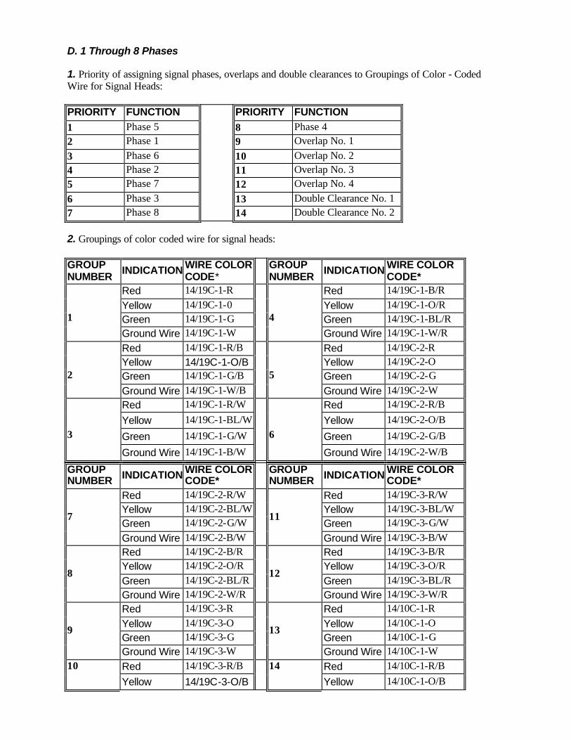
D. 1 Through 8 Phases 1. Priority of assigning signal phases, overlaps and double clearances to Groupings of Color - Coded Wire for Signal Heads: PRIORITY FUNCTION PRIORITY FUNCTION 1 Phase 5 8 Phase 4 2 Phase 1 9 Overlap No. 1 3 Phase 6 10 Overlap No. 2 4 Phase 2 11 Overlap No. 3 5 Phase 7 12 Overlap No. 4 6 Phase 3 13 Double Clearance No. 1 7 Phase 8
14 Double Clearance No. 2
2. Groupings of color coded wire for signal heads: GROUP NUMBER INDICATION WIRE COLOR
CODE* GROUP NUMBER INDICATION WIRE COLOR
CODE* Red 14/19C-1-R Red 14/19C-1-B/R Yellow 14/19C-1-0 Yellow 14/19C-1-O/R Green 14/19C-1-G Green 14/19C-1-BL/R
1
Ground Wire 14/19C-1-W
4
Ground Wire 14/19C-1-W/R Red 14/19C-1-R/B Red 14/19C-2-R Yellow 14/19C-1-O/B Yellow 14/19C-2-O Green 14/19C-1-G/B Green 14/19C-2-G
2
Ground Wire 14/19C-1-W/B
5
Ground Wire 14/19C-2-W Red 14/19C-1-R/W Red 14/19C-2-R/B
Yellow 14/19C-1-BL/W Yellow 14/19C-2-O/B
Green 14/19C-1-G/W Green 14/19C-2-G/B 3
Ground Wire 14/19C-1-B/W
6
Ground Wire 14/19C-2-W/B
GROUP NUMBER INDICATION WIRE COLOR
CODE* GROUP NUMBER INDICATION WIRE COLOR
CODE* Red 14/19C-2-R/W Red 14/19C-3-R/W Yellow 14/19C-2-BL/W Yellow 14/19C-3-BL/W Green 14/19C-2-G/W Green 14/19C-3-G/W 7
Ground Wire 14/19C-2-B/W
11
Ground Wire 14/19C-3-B/W Red 14/19C-2-B/R Red 14/19C-3-B/R Yellow 14/19C-2-O/R Yellow 14/19C-3-O/R Green 14/19C-2-BL/R Green 14/19C-3-BL/R
8
Ground Wire 14/19C-2-W/R
12
Ground Wire 14/19C-3-W/R Red 14/19C-3-R Red 14/10C-1-R Yellow 14/19C-3-O Yellow 14/10C-1-O Green 14/19C-3-G Green 14/10C-1-G
9
Ground Wire 14/19C-3-W
13
Ground Wire 14/10C-1-W Red 14/19C-3-R/B Red 14/10C-1-R/B 10
Yellow 14/19C-3-O/B
14
Yellow 14/10C-1-O/B

Green 14/19C-3-G/B Green 14/10C-1-G/B Ground Wire 14/19C-3-W/B
Ground Wire 14/10C-1-W/B
E. Groupings of Color Coded Wire for Preempts (Blue Light) and Pedestrian Signals: 1. Preempts (Blue Light). WIRE COLOR CODE INDICATION 14/2C-1-B Blue Light 14/2C-1 -W Ground Wire 2. Pedestrians Signals. PED NUMBER
WIRE COLOR CODE* INDICATION PED
NUMBER WIRE COLOR CODE* INDICATION
14/5C-1-P/R DONT WALK 14/5C-3-P/R DONT WALK 14/5C-1-P/G WALK 14/5C-3-P/G WALK 14/5C-1-P/B Switch Wire 14/5C-3-P/B Switch Wire 14/5C-1-P/O Switch Wire 14/5C-3-P/O Switch Wire
1
14/5C-1-P/W Ground Wire
3
14/5C-3-P/W Ground Wire 14/5C-2-P/R DONT WALK 14/5C-4-P/R DONT WALK 14/5C-2-P/G WALK 14/5C-4-P/G WALK
14/5C-2-P/B Switch Wire 14/5C-4-P/B Switch Wire 14/5C-2-P/O Switch Wire 14/5C-4-P/O Switch Wire
2
14/5C-2-P/W Ground Wire
4
14/5C-4-P/W Ground Wire * Key for Wire Color Code: XX / XXC - X - X / X AWG No. of Cable No. Color Tracer Conductors For the Given of Wire Color Conductor Size Colors: R-Red, O-Orange, G-Green, BL-Blue, W-White, B-Black. F. Notes: The following steps should be used to determine the appropriate color coded wiring for a given signal installation: 1. Determine which functions are used in the signal operation. 2. Assign the color coded wire to the functions used in numerical order according to the priority given to the function . 3. Use the minimum number of conductors required to maintain the color code. EXAMPLE: Signal X is a four phase signal Step No.1-- Phase 1, 5, 6, 4, and an overlap of Phase 6 + 4 is used in the Signal operation. Step No. 2-- Priority Function Color Coded Group No. 1 5 1 2 1 2 3 6 3 8 4 4

9 Overlap No. 1 5 Step No.3-- Use one 19 conductor cable and one five conductor cable 680-3.23 Pedestrian Push Button and Sign. The push button and sign shall be installed and constructed in accordance with the details specified on the standard sheets. Push button and sign shall be installed on either an existing pole, a newly installed signal pole or on its own post and footing as specified on the plans. The orientation shall be convenient to pedestrians intending to cross the street controlled by the push button at the marked or obvious crosswalk. 680-3.24 Fire Pre-Emption Tell Tale Light. The Tell Tale Light shall be installed in accordance with details on the standard sheets or as directed by the Engineer. The light shall be wired in such a manner as to simultaneously display a blue light during the emergency pre-emption interval and at other times remain unlighted. It shall be oriented in the position which provides the best view to the emergency equipment approach roadway. 680-3.25 Flashing Beacon Sign Assembly. The flashing beacon sign assembly shall be constructed as shown on the plans, and standard sheets. It shall be installed on either an existing sign and post or a new pole as specified on the plans. The sign panel shall be constructed in accordance with the appropriate subsections of Section 645, Guide Signs, Traffic Signs and Special Devices. The flashing beacon signal heads and solid state flasher and cabinet shall be installed as shown on the standard sheets. When not mounted behind guiderail, the pole shall be equipped with an approved breakaway base or transformer base fabricated in accordance with §723-15.01--Breakaway Transformer Base (Aluminum). 680-3.26 Inductance Loop Installation. Loops shall be installed in accordance with the details specified on the plans, Standard Sheets or as directed by the Engineer. Loop dimensions shall be as specified on the plans. Pullboxes, conduits and curb cuts shall be completed before beginning the loop installation. The loop shall be outlined on the pavement to conform to the specified configuration. A power saw and wet cutting techniques shall be used to cut a slot in the pavement. Dry cutting techniques shall be used if directed by the Engineer and with appropriate measures to safeguard nearby vehicle and pedestrian traffic. The cut shall be 9.5 mm in width and the depth specified on the standard sheets. The corners shall be cored, drilled or chipped out as shown on the standard sheets. Sharp edges in the corners shall be smoothed. All saw cuts and corners shall be of the same depth. Immediately after sawing by either wet or dry methods, the slot and pavement shall be flushed with pressurized clean water to remove the saw slurry, dust or other cutting debris. Filtered compressed air shall be used to remove all dust and moisture from the slot. If the slot is damp, do not proceed with the installation until it is dry. Hot air may be used to dry the saw slot. At the edge of pavement or curb a 25 mm minimum diameter, Metal Steel Conduit, Zinc Coated, Flexible Liquid-Tight Steel Conduit or Rigid Plastic Conduit shall be installed between the pavement and pullbox in accordance with details specified on the standard sheets. The curb or pavement shall be cut or scored to leave a permanent mark to show where the conduit runs under the curb or pavement. The loop wire shall be installed starting at the roadside pullbox, passed around the loop for the specified number of turns and brought back to the pullbox. Splices shall not be permitted outside the pullbox. The wire shall be depressed in the slot without the use of sharp objects which might damage the wire insulation. The loop shall be held in place every 0.6 m with 25 mm (approximate) strips of rubber, neoprene, flexible tubing or foam backer rod as approved by the Engineer. These hold down strips shall be left in place when the slot is filled with Roadway Loop Embedding Sealer. The pair of loop wires between the edge of pavement and the splice to the shielded lead-in cable in the pullbox shall be twisted together with at least five turns per 0.3 m. The splice between the loop wires (twisted pair) and the shielded lead-in cable shall be moisture proof and shall have a dielectric strength at least equal to that of the original insulation.
The bared conductor ends shall be either twisted and soldered or joined using an uninsulated, size coded solderless type connector of the correct size using an appropriate crimping tool. The splice shall be reinsulated in accordance with §680-3.16 Cable Splices, Method No. I except that heat shrinkage polyolefin tubing may be used as an alternate to the rubber tape; also, the first layer of PVC tape and sealing agent shall be extended as needed to cover a minimum of 25 mm of the inductance loop wire tube. The polyolefin tubing shall be at least as thick as the original insulation. Upon completion of the reinsulating, a final waterproof coating shall be applied over the entire splice. The loop wires (twisted pair) and the splice to the shielded lead-in cable with the pullbox shall be held by wire hangers as near as possible to the top of the box in order to prevent their immersion in water. The shielded lead-in cable shall be continuous (no splices) from the splice to the loop wires to the controller cabinet terminals. The drain or ground wire in the shielded cable shall be grounded at the controller cabinet terminals only. The completed loop installation including the shielded lead-in to the controller cabinet shall have a minimum of 50 megohms leakage resistance to ground. This resistance shall be tested before the loop is sealed in the pavement and after the splice is made between the loop wires (twisted pair) and shielded lead-in. Resistance to ground shall be tested in accordance with the Insulation Resistance Test in §680-3.32. When it is determined that the resistance to ground requirements are met, the slot shall be filled with Roadway Loop Embedding Sealer. The pavement temperature shall be at least 4.4EC and rising before the sealer is placed. All work involving the sealer shall be done in compliance with the manufacturer's specifications. When the loop embedding sealer has set sufficiently to open the loop to traffic, but the surface remains tacky, the loop may be dusted with cement dust to facilitate opening the loop to traffic. 680-3.27 Concrete Base for Controller Cabinet. Bases shall be installed and constructed in accordance with the details specified on the standard sheets. Bases shall be either pre-cast or cast-in-place. Anchor bolts shall be placed in the footing at the proper location. Conduits shall be installed in the footing as required by the plans. Where the base is installed in unpaved areas a work pad shall be constructed in front of the cabinet door. Excavation shall be in accordance with §680-3.09, Excavation. 680-3.28 Power Meter Base. At each power source, the Contractor shall provide two meters of slack in the traffic signal cable used for power supply and neatly coil this slack within the controller cabinet. The Contractor shall install a meter base as shown on the standard sheets or as ordered by the Engineer. The meter base will be furnished by the utility company. The additional length of power cable in the controller cabinet shall be extended through the cabinet wall into the meter base and back to the controller circuit breaker. All meter base fittings shall be weather tight. 680-3.29 Overhead Traffic Signs. Sign and mounting brackets shall be installed as shown on the plans and standard sheets. Signs shall be aligned to the satisfaction of the Engineer. Sign Panels shall be aluminum and constructed in accordance with the appropriate subsections of section 645--Guide Signs, Traffic Signs and Special Devices. 680-3.30 Field Galvanizing. All abrasions of galvanized steel due to handling equipment, erection, etc., and all points of attachment, shall be field repaired as specified in §719-01--Galvanized Coatings and Repair Methods. 680-3.31 Cast Iron Junction Boxes. Junction boxes shall be installed at the locations and according to the details on the plans or as directed by the Engineer. Dimensions shall be as shown on the plans. 680-3.32 Tests. The Contractor shall perform all tests described herein in the presence of the Engineer or his representative. Testing equipment shall be supplied by the Contractor. Prior to placing a signal in operation, the Contractor shall perform the following tests: A. Continuity Test. Each circuit shall be tested for continuity.
B. Ground Test. All traffic signal grounding systems when completed in place shall have a resistance to ground of not more than that shown in the table below as determined in the following manner: 1. Temporarily connect a 10 ampere load between the AC + side of the equipment cabinet fuse and the ground system. It should be assured that the power company applied voltage is 120 volts AC at the time of the test. 2. Disconnect the power company AC neutral from the ground system. 3. Connect a voltmeter between the power company AC neutral and the ground system. Controller Voltmeter Equivalent Installed Reading (Volts) Resistance (Ohms) 2 Phase 20 2.0 Model 170 Microcomputer 20 2.0 All others 10 1.0 If the voltmeter reading is higher than the appropriate voltage shown in the above table under the 10 ampere load, the grounding system has an unacceptable resistance to ground. Additional grounding, including electrical bonding of underground metallic conduit, may be necessary in order to meet the requirements of this test. C. Insulation Resistance Test. An insulation resistance test at 500 volts DC shall be made on each circuit between the circuit and ground. The insulation resistance shall not be less than 10 megohms on each circuit except that inductive loop detector circuits shall have an insulation resistance of not less than 50 megohms. The insulation resistance test shall not be performed on magnetometer sensing elements. Splices in the pullbox adjacent to the magnetometer sensing elements shall not be made prior to performing an insulation resistance test on the lead-in conductors between the pullbox and the controller cabinet field terminals. D. Functional Test. After satisfactory completion of all other tests, a functional test of the traffic signal control equipment shall be performed to demonstrate that every part of the signal system operates in accordance with the plans, specifications and to the satisfaction of the Engineer. The functional test for each signal system shall consist of not less than ten days of continuous satisfactory operation. If unsatisfactory performance of the system components is discovered during this time, the condition shall be corrected and the test repeated until ten days of continuous satisfactory operation is obtained. Functional tests shall not begin on a Friday or on the day before a legal holiday. On the day the functional test begins, initial turn-on shall be made between the hours of 9:00 am and 2:00 pm unless otherwise ordered by the Engineer. Prior to turn-on all signal control equipment required for signal system shall be installed and ready for operation including pedestrian signal indications, pedestrian signs and push buttons, and vehicle detectors. All louvers, visors, and signal heads shall be directed to provide maximum visibility. Temporary shut downs caused by power interruption or traffic accidents shall not constitute discontinuity of the functional test. 680-3.33 Fiberoptic Pedestrian Signal Heads. Fiberoptic pedestrian signal heads shall be installed according to the requirements of §680-3.21 Signal Heads. 680-3.34 Fiberoptic Dual Indication Arrow. Fiberoptic dual indication arrows shall be installed according to the requirements of §680-3.21 Signal Heads. 680-3.35 Strobing Signal Section. Strobing Signal Sections shall be installed according to the requirements of §680-3.21 Signal Heads. 680-3.36 LED Traffic Signal Module. LED Traffic Signal Modules shall be installed in Type I Traffic Signal Sections according to the requirements of §680-3.21 Signal Heads.
680-3.37 LED Pedestrian Signal Module. LED Pedestrian Signal Modules shall be installed in Type I Pedestrian Signal Section according to the requirements of §680-3.21 Signal Heads. 680-4 METHOD OF MEASUREMENT 680-4.01 Each Unit. The following items will be measured for payment as the number of each unit furnished and installed in accordance with the contract documents or as directed by the Engineer: Span Wire Assembly Guy Assembly Pedestrian Signal Section Pullbox Cast Iron Junction Box Controller Assembly Component Fire Pre-Emption Tell Tale Light Concrete Base for Controller Cabinet Fiberoptic Dual Indication Arrow LED Pedestrian Signal Module Type I Pedestrian Signal Section Pedestrian Push Button and Sign
Traffic Signal Section Strobing Signal Indication Traffic Signal Bracket Assembly Traffic Signal Disconnect Hanger Riser Assembly Traffic Signal Pole Overhead Sign Assembly Flashing Beacon Sign Assembly Fiberoptic Pedestrian Signal Section LED Traffic Signal Module Type I Traffic Signal Section
680-4.02 Linear Meter Measurements. The following items will be measured for payment as the number of meters actually installed in accordance with the contract documents or as directed by the Engineer: Inductance Loop Wire Shielded Lead-ln Cable Inductance Loop Installation Messenger Assembly Signal Cable
Shielded Communication Cable Signal Cable with Integral Messenger Shielded Communication Cable w/ Integral Messenger Conduit
Inductance loop wire shall be the actual number of meters of wire used and left in place. Measurement of inductance loop installation shall be the number of meters of pavement sawcut. 680-4.03 Pole Excavation and Concrete Foundation. The payment quantity of pole excavation and concrete foundation shall be the number of cubic meters of concrete shown in the table on the standard sheet for Traffic Signal Pole Foundations for the specified footing size. No adjustment will be made when the Contractor elects to install a square footing. When a square footing is specified on the plans, the payment quantity shown in the table will be multiplied by a factor of 1.3. 680-4.04 Conduit Jacking or Boring. The quantity of conduit jacking or boring shall be the number of linear meters as computed from the payment limits specified in the contract documents. 680-5 BASIS OF PAYMENT 680-5.01 General. The unit price bid for all items of work encompassed by this Section shall include the furnishing of all labor, materials, tools, equipment, safety requirements as determined by U.S. Department of Labor's Occupational Safety and Health Standards, and incidentals as necessary to complete the work of the item installed in place and performing all tests to the satisfaction of the Engineer. No direct payment will be made for the installation of the power service connection and meter base but the cost shall be covered in the various traffic signal items. Items with additional provisions are as follows: 680-5.02 Pedestrian Signal Section. The unit price bid for each section shall include one “WALK” and one “DONT WALK” indication, and all necessary internal wiring, visor(s) and lamp(s).

680-5.03 Pedestrian Signal Bracket Assembly. The unit price bid for each bracket assembly shall include the bracket, fittings, wiring of the head assembly and installation. 680-5.04 Pole Excavation and Concrete Foundation. The unit price bid per cubic meter shall include the excavation, any protective system(s) required to ensure the safety of the workers and the public, backfill (select granular backfill or concrete), form work, concrete, bar reinforcement for concrete, excavation and backfilling of test holes, conduit bends and fittings, restoration of surfaces in kind, and sawcutting. Progress payments will be made at the unit price bid for 80 percent of the quantity for each foundation properly installed except for the mortar cap and restoration. The remaining 20 percent will be paid for upon satisfactory completion of each footing. 680-5.05 Pullbox. The unit price bid for each pullbox shall include all concrete, reinforcing steel, crushed stone or gravel, extensions, sawcutting, excavation, backfill, frames, covers, restoration of surfaces and incidentals as required. 680-5.06 Conduit. The unit price bid shall include all handling, cutting, bending, fitting, capping, painting, testing, furnishing and placing pull lines, condulets and concrete inserts, expansion and incidental fittings as required. Conduit bends and fittings in concrete footings will be paid for under the respective footing item. Conduit excavation and backfill and jacking or boring will be paid for under their respective items. 680-5.07 Inductance Loop Installation. The unit price bid per linear meter shall include the cost of all pavement sawing and drilling, loop embedding sealer, and pavement cut-outs. Inductance Loop Wire, pullboxes, Shielded lead-in Cable, Vehicle Detector Inductance Loop, Conduit, and Conduit Excavation and Backfill shall be paid under their respective items. 680-5.08 Controller Assembly. The unit price bid for each component of the Controller Assembly shall include all labor, material and equipment necessary to complete the work. The cost of the necessary grounding system shall be included in the unit price bid for the controller assembly components. Progress payments will be made in the following manner: Sixty-five percent of the bid price of each component will be paid after it is installed and ready for testing. Twenty-five percent of the bid price will be paid after satisfactory completion of all tests required by these specifications, including the function test for ten days of continuous satisfactory operation of the traffic signal system at each signalized location. The remaining ten percent will be paid when all the traffic signals in the contract are functioning to the satisfaction of the Engineer. 680-5.09 Fire Pre-Emption Tell Tale Light. The unit price bid shall include the light fixture, bulb, nipple, guard, and all attachments and fittings as required. 680-5.10 Concrete Base for Controller Cabinet. The unit price bid for each base shall include the cost of all sawcutting, excavation, backfill, form work, restoration of surfaces, concrete, test holes, conduit bends and fittings, and concrete work pad. 680-5.11 Pedestrian Push Button and Sign. The unit price bid shall include the push button, sign, mounting hardware, pole drilling, and necessary fittings as required. Where the push button and sign is installed on its own post the unit price shall also include the cost of the post, sawcutting, excavation, backfill, concrete, restoration of surfaces, and conduit bend and fittings. 680-5.12 Jacking or Boring. The unit price bid per meter shall include excavation, backfilling for jacking or boring pits; test holes; and restoration of surfaces in kind.
680-5.13 Signal Cable and Shielded Communication Cable. The unit price bid per meter shall include the connectors, lashing or messenger rings or plastic cable bands, splices when permitted, testing, cable markers, and incidental fittings for the cable connected in place. 680-5.14 Signal Cable with Integral Messenger and Shielded Communication Cable with Integral Messenger. The unit price bid per meter shall include connectors, splices when permitted, testing, cable markers, hardware and fittings to attach the cable to the pole and other incidentals for the cable connected in place. 680-5.15 Traffic Signal Sections. The unit price bid shall include housing, visors, lamps, lenses and incidentals to make an individual signal head section. 680-5.16 Traffic Signal Bracket Assembly. The unit price bid shall include all brackets, elbows, arms and fittings to attach the signal to span wire, pole and mast arm. It shall include all labor and materials to assemble the individual signal sections and brackets to form a complete signal head including internal wiring and installation on the span wire, pole and mast arm. 680-5.17 Traffic Signal Disconnect Hanger. The unit price bid shall include the disconnect hanger, wiring to the signal head and signal cable and installation on the signal head. 680-5.18 Traffic Signal Poles. The unit price bid for each pole shall include all the items specified in §680-3.11 and the necessary grounding system, anchor bolts, mast arms, lighting arms, pole assembly and erections, and field galvanizing as required. Breakaway transformer bases when specified shall be included in the price bid for each pole. 680-5.19 Overhead Sign Assembly. The unit price bid shall include the mounting brackets attaching the sign to signal head, span wire, pole , and mast arm, sign panel and incidental hardware and fittings. 680-5.20 Flashing Beacon Sign Assembly. The unit price bid shall include the flashing beacon signal head, two circuit flasher and cabinet, sign panel and mounting brackets and all other necessary hardware. The cost of the pole and pole excavation and concrete foundation will be paid for under their respective items. The cost of any necessary breakaway base shall be included in the cost of the pole. 680-5.21 LED Traffic Signal Module. The unit price bid shall include the LED module, the removal of existing components if necessary, and installation of the LED module on the signal head. 680-5.22 LED Pedestrian Signal Module. The unit price bid shall include the LED module, the removal of existing components if necessary, and installation of the LED module on the pedestrian signal head. 680-5.23 Type I Traffic Signal Section. The unit price bid shall include housing, door, visor and incidentals to make an individual Type I Signal Head Section. 680-5.24 Type I Pedestrian Signal Section. The unit price bid shall include housing, door, visor and incidentals to make an individual Type I Pedestrian Signal Section. 680-5.25 LED Traffic Signal Module Installation. The unit price bid shall include the cost of labor, materials, and equipment required to remove existing components if necessary, and install the State supplied Traffic Signal Modules as shown on the plans or as ordered by the Engineer. 680-5.26 LED Pedestrian Signal Module Installation. The unit price bid shall include the cost of labor, materials, and equipment required to remove existing components if necessary, and install the State supplied Pedestrian Signal Modules as shown on the plans or as ordered by the Engineer. Payment will be made under:
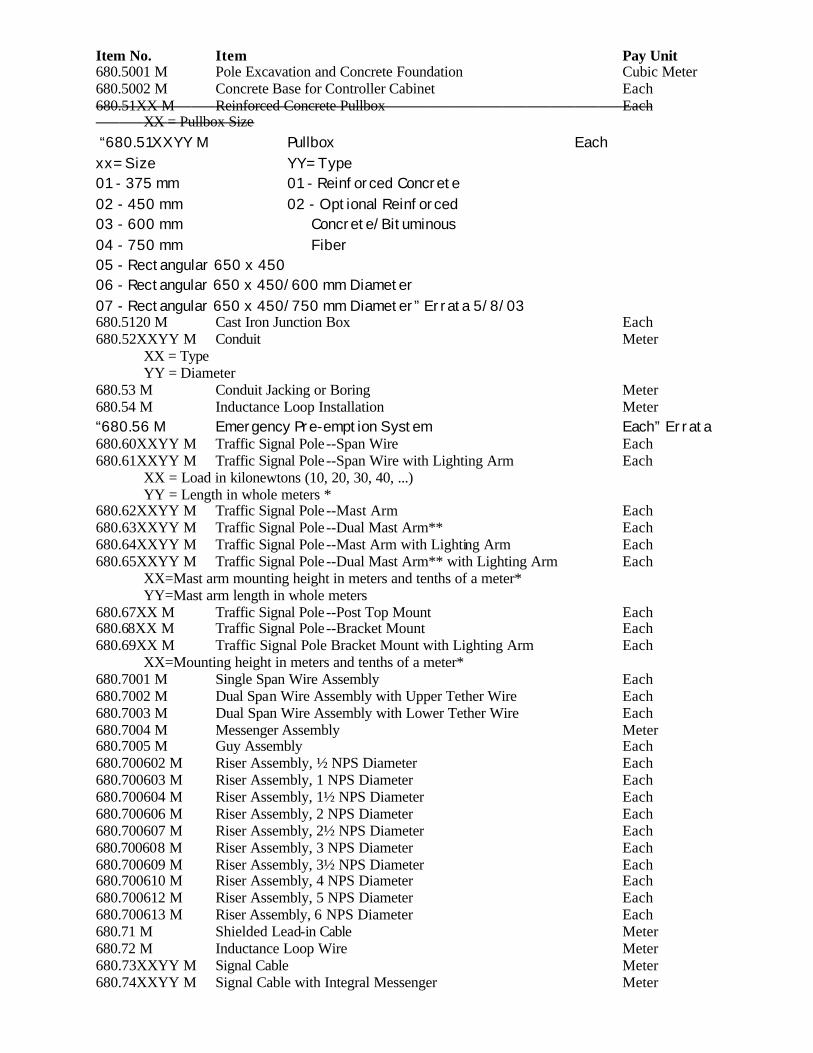
Item No. Item Pay Unit 680.5001 M Pole Excavation and Concrete Foundation Cubic Meter 680.5002 M Concrete Base for Controller Cabinet Each 680.51XX M Reinforced Concrete Pullbox Each XX = Pullbox Size “680.51XXYY M Pullbox Each xx= Size YY= Type 01 - 375 mm 01 - Reinforced Concrete 02 - 450 mm 02 - Optional Reinforced 03 - 600 mm Concrete/Bituminous 04 - 750 mm Fiber 05 - Rectangular 650 x 450 06 - Rectangular 650 x 450/600 mm Diameter 07 - Rectangular 650 x 450/750 mm Diameter” Errata 5/8/03 680.5120 M Cast Iron Junction Box Each 680.52XXYY M Conduit Meter XX = Type YY = Diameter 680.53 M Conduit Jacking or Boring Meter 680.54 M Inductance Loop Installation Meter “680.56 M Emergency Pre-emption System Each” Errata 680.60XXYY M Traffic Signal Pole --Span Wire Each 680.61XXYY M Traffic Signal Pole --Span Wire with Lighting Arm Each XX = Load in kilonewtons (10, 20, 30, 40, ...) YY = Length in whole meters * 680.62XXYY M Traffic Signal Pole --Mast Arm Each 680.63XXYY M Traffic Signal Pole --Dual Mast Arm** Each 680.64XXYY M Traffic Signal Pole --Mast Arm with Lighting Arm Each 680.65XXYY M Traffic Signal Pole --Dual Mast Arm** with Lighting Arm Each XX=Mast arm mounting height in meters and tenths of a meter* YY=Mast arm length in whole meters 680.67XX M Traffic Signal Pole --Post Top Mount Each 680.68XX M Traffic Signal Pole --Bracket Mount Each 680.69XX M Traffic Signal Pole Bracket Mount with Lighting Arm Each XX=Mounting height in meters and tenths of a meter* 680.7001 M Single Span Wire Assembly Each 680.7002 M Dual Span Wire Assembly with Upper Tether Wire Each 680.7003 M Dual Span Wire Assembly with Lower Tether Wire Each 680.7004 M Messenger Assembly Meter 680.7005 M Guy Assembly Each 680.700602 M Riser Assembly, ½ NPS Diameter Each 680.700603 M Riser Assembly, 1 NPS Diameter Each 680.700604 M Riser Assembly, 1½ NPS Diameter Each 680.700606 M Riser Assembly, 2 NPS Diameter Each 680.700607 M Riser Assembly, 2½ NPS Diameter Each 680.700608 M Riser Assembly, 3 NPS Diameter Each 680.700609 M Riser Assembly, 3½ NPS Diameter Each 680.700610 M Riser Assembly, 4 NPS Diameter Each 680.700612 M Riser Assembly, 5 NPS Diameter Each 680.700613 M Riser Assembly, 6 NPS Diameter Each 680.71 M Shielded Lead-in Cable Meter 680.72 M Inductance Loop Wire Meter 680.73XXYY M Signal Cable Meter 680.74XXYY M Signal Cable with Integral Messenger Meter
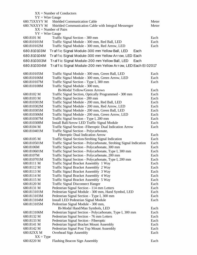
XX = Number of Conductors YY = Wire Gauge 680.75XXYY M Shielded Communication Cable Meter 680.76XXYY M Shielded Communication Cable with Integral Messenger Meter XX = Number of Pairs YY = Wire Gauge 680.8101 M Traffic Signal Section - 300 mm Each 680.810101M Traffic Signal Module - 300 mm, Red Ball, LED Each 680.810102M Traffic Signal Module - 300 mm, Red Arrow, LED Each 680.810103M Traffic Signal Module-300 mm Yellow Ball, LED Each 680.810104M Traffic Signal Module-300 mm Yellow Arrow, LED Each 680.810303M Traffic Signal Module-200 mm Yellow Ball, LED Each 680.810304M Traffic Signal Module-200 mm Yellow Arrow, LED Each EI02017 680.810105M Traffic Signal Module - 300 mm, Green Ball, LED Each 680.810106M Traffic Signa l Module - 300 mm, Green Arrow, LED Each 680.810107M Traffic Signal Section - Type I, 300 mm Each 680.810108M Traffic Signal Module - 300 mm, Bi-Modal Yellow/Green Arrows Each 680.8102 M Traffic Signal Section, Optically Programmed - 300 mm Each 680.8103 M Traffic Signal Section - 200 mm Each 680.810301M Traffic Signal Module - 200 mm, Red Ball, LED Each 680.810302M Traffic Signal Module - 200 mm, Red Arrow, LED Each 680.810305M Traffic Signal Module - 200 mm, Green Ball, LED Each 680.810306M Traffic Signal Module - 200 mm, Green Arrow, LED Each 680.810307M Traffic Signal Section - Type I, 200 mm Each 680.810308M Install Ball/Arrow LED Traffic Signal Module Each 680.8104 M Traffic Signal Section -Fiberoptic Dual Indication Arrow Each 680.810401M Traffic Signal Section - Polycarbonate, Fiberoptic Dual Indication Arrow Each 680.8105 M Traffic Signal Section-Strobing Signal Indication Each 680.810501M Traffic Signal Section - Polycarbonate, Strobing Signal Indication Each 680.8106M Traffic Signal Section - Polycarbonate, 300 mm Each 680.810601M Traffic Signal Section - Polycarbonate, Type I, 300 mm Each 680.8107M Traffic Signal Section - Polycarbonate, 200 mm Each 680.810701M Traffic Signal Section - Polycarbonate, Type I, 200 mm Each 680.8111 M Traffic Signal Bracket Assembly 1 Way Each 680.8112 M Traffic Signal Bracket Assembly 2 Way Each 680.8113 M Traffic Signa l Bracket Assembly 3 Way Each 680.8114 M Traffic Signal Bracket Assembly 4 Way Each 680.8115 M Traffic Signal Bracket Assembly 5 Way Each 680.8120 M Traffic Signal Disconnect Hanger Each 680.8131 M Pedestrian Signal Section - 114 mm Letters Each 680.813101M Pedestrian Signal Module - 300 mm, Hand Symbol, LED Each 680.813103M Pedestrian Signal Section - Type I, 300 mm Each 680.813104M Install LED Pedestrian Signal Module Each 680.813105M Pedestrian Signal Module - 300 mm, Bi-Modal Hand/Man Symbols, LED Each 680.813106M Pedestrian Signal Section - Polycarbonate, Type I, 300 mm Each 680.8132 M Pedestrian Signal Section - 76 mm Letters Each 680.8133 M Pedestrian Signal Section - Fiberoptic Each 680.8141 M Pedestrian Signal Bracket Mount Assembly Each 680.8142 M Pedestrian Signal Post Top Mount Assembly Each 680.82XX M Overhead Sign Assembly Each XX = Type 680.8220 M Flashing Beacon Sign Assembly Each
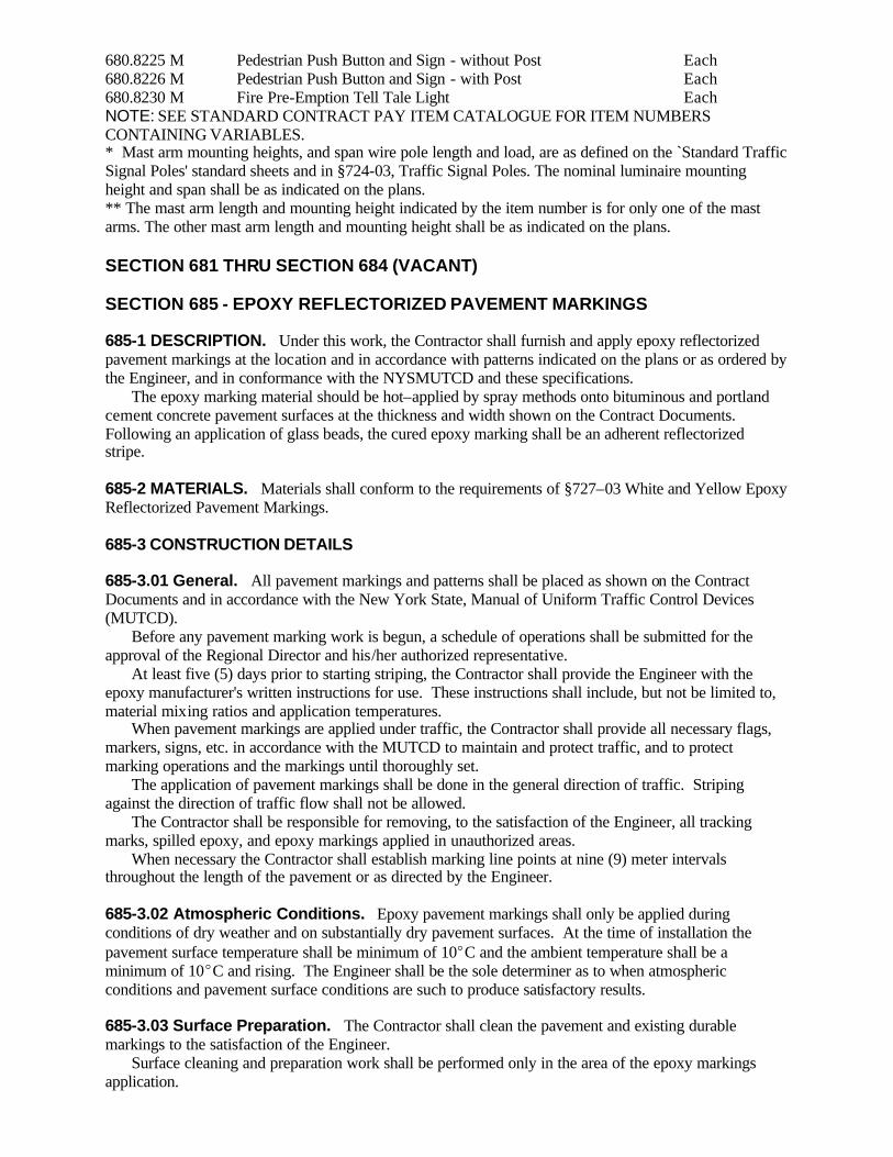
680.8225 M Pedestrian Push Button and Sign - without Post Each 680.8226 M Pedestrian Push Button and Sign - with Post Each 680.8230 M Fire Pre-Emption Tell Tale Light Each NOTE: SEE STANDARD CONTRACT PAY ITEM CATALOGUE FOR ITEM NUMBERS CONTAINING VARIABLES. * Mast arm mounting heights, and span wire pole length and load, are as defined on the `Standard Traffic Signal Poles' standard sheets and in §724-03, Traffic Signal Poles. The nominal luminaire mounting height and span shall be as indicated on the plans. ** The mast arm length and mounting height indicated by the item number is for only one of the mast arms. The other mast arm length and mounting height shall be as indicated on the plans. SECTION 681 THRU SECTION 684 (VACANT) SECTION 685 - EPOXY REFLECTORIZED PAVEMENT MARKINGS 685-1 DESCRIPTION. Under this work, the Contractor shall furnish and apply epoxy reflectorized pavement markings at the location and in accordance with patterns indicated on the plans or as ordered by the Engineer, and in conformance with the NYSMUTCD and these specifications. The epoxy marking material should be hot–applied by spray methods onto bituminous and portland cement concrete pavement surfaces at the thickness and width shown on the Contract Documents. Following an application of glass beads, the cured epoxy marking shall be an adherent reflectorized stripe. 685-2 MATERIALS. Materials shall conform to the requirements of §727–03 White and Yellow Epoxy Reflectorized Pavement Markings. 685-3 CONSTRUCTION DETAILS 685-3.01 General. All pavement markings and patterns shall be placed as shown on the Contract Documents and in accordance with the New York State, Manual of Uniform Traffic Control Devices (MUTCD). Before any pavement marking work is begun, a schedule of operations shall be submitted for the approval of the Regional Director and his/her authorized representative. At least five (5) days prior to starting striping, the Contractor shall provide the Engineer with the epoxy manufacturer's written instructions for use. These instructions shall include, but not be limited to, material mixing ratios and application temperatures. When pavement markings are applied under traffic, the Contractor shall provide all necessary flags, markers, signs, etc. in accordance with the MUTCD to maintain and protect traffic, and to protect marking operations and the markings until thoroughly set. The application of pavement markings shall be done in the general direction of traffic. Striping against the direction of traffic flow shall not be allowed. The Contractor shall be responsible for removing, to the satisfaction of the Engineer, all tracking marks, spilled epoxy, and epoxy markings applied in unauthorized areas. When necessary the Contractor shall establish marking line points at nine (9) meter intervals throughout the length of the pavement or as directed by the Engineer. 685-3.02 Atmospheric Conditions. Epoxy pavement markings shall only be applied during conditions of dry weather and on substantially dry pavement surfaces. At the time of installation the pavement surface temperature shall be minimum of 10EC and the ambient temperature shall be a minimum of 10EC and rising. The Engineer shall be the sole determiner as to when atmospheric conditions and pavement surface conditions are such to produce satisfactory results. 685-3.03 Surface Preparation. The Contractor shall clean the pavement and existing durable markings to the satisfaction of the Engineer. Surface cleaning and preparation work shall be performed only in the area of the epoxy markings application.
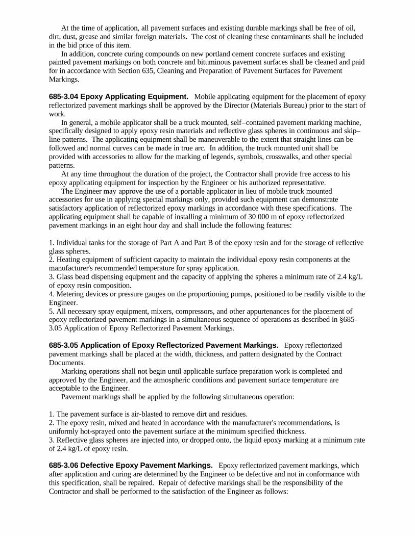
At the time of application, all pavement surfaces and existing durable markings shall be free of oil, dirt, dust, grease and similar foreign materials. The cost of cleaning these contaminants shall be included in the bid price of this item. In addition, concrete curing compounds on new portland cement concrete surfaces and existing painted pavement markings on both concrete and bituminous pavement surfaces shall be cleaned and paid for in accordance with Section 635, Cleaning and Preparation of Pavement Surfaces for Pavement Markings. 685-3.04 Epoxy Applicating Equipment. Mobile applicating equipment for the placement of epoxy reflectorized pavement markings shall be approved by the Director (Materials Bureau) prior to the start of work. In general, a mobile applicator shall be a truck mounted, self–contained pavement marking machine, specifically designed to apply epoxy resin materials and reflective glass spheres in continuous and skip–line patterns. The applicating equipment shall be maneuverable to the extent that straight lines can be followed and normal curves can be made in true arc. In addition, the truck mounted unit shall be provided with accessories to allow for the marking of legends, symbols, crosswalks, and other special patterns. At any time throughout the duration of the project, the Contractor shall provide free access to his epoxy applicating equipment for inspection by the Engineer or his authorized representative. The Engineer may approve the use of a portable applicator in lieu of mobile truck mounted accessories for use in applying special markings only, provided such equipment can demonstrate satisfactory application of reflectorized epoxy markings in accordance with these specifications. The applicating equipment shall be capable of installing a minimum of 30 000 m of epoxy reflectorized pavement markings in an eight hour day and shall include the following features: 1. Individual tanks for the storage of Part A and Part B of the epoxy resin and for the storage of reflective glass spheres. 2. Heating equipment of sufficient capacity to maintain the individual epoxy resin components at the manufacturer's recommended temperature for spray application. 3. Glass bead dispensing equipment and the capacity of applying the spheres a minimum rate of 2.4 kg/L of epoxy resin composition. 4. Metering devices or pressure gauges on the proportioning pumps, positioned to be readily visible to the Engineer. 5. All necessary spray equipment, mixers, compressors, and other appurtenances for the placement of epoxy reflectorized pavement markings in a simultaneous sequence of operations as described in §685-3.05 Application of Epoxy Reflectorized Pavement Markings. 685-3.05 Application of Epoxy Reflectorized Pavement Markings. Epoxy reflectorized pavement markings shall be placed at the width, thickness, and pattern designated by the Contract Documents. Marking operations shall not begin until applicable surface preparation work is completed and approved by the Engineer, and the atmospheric conditions and pavement surface temperature are acceptable to the Engineer. Pavement markings shall be applied by the following simultaneous operation: 1. The pavement surface is air-blasted to remove dirt and residues. 2. The epoxy resin, mixed and heated in accordance with the manufacturer's recommendations, is uniformly hot-sprayed onto the pavement surface at the minimum specified thickness. 3. Reflective glass spheres are injected into, or dropped onto, the liquid epoxy marking at a minimum rate of 2.4 kg/L of epoxy resin. 685-3.06 Defective Epoxy Pavement Markings. Epoxy reflectorized pavement markings, which after application and curing are determined by the Engineer to be defective and not in conformance with this specification, shall be repaired. Repair of defective markings shall be the responsibility of the Contractor and shall be performed to the satisfaction of the Engineer as follows:

1. Insufficient film thickness and line width; insufficient glass bead coverage or inadequate glass bead retention. Repair Method. Prepare the surface of the defective epoxy marking by grinding or blast cleaning. No other cleaning methods will be allowed. Surface preparation shall be performed to the extent that a substantial amount of the reflective glass spheres are removed and a roughened epoxy marking surface remains. Immediately after surface preparation remove loose particles and foreign debris by brooming or blasting with compressed air. Repair shall be made by restriping over the cleaned surface in accordance with the requirements of this specification and at the full thickness indicated on the Contract Documents. 2. Uncured or discolored epoxy*; insufficient bond (to pavement surface or existing durable marking). Repair Method. The defective epoxy marking shall be completely removed and cleaned to the underlying pavement surface in accordance with the requirements of Section 635 – Cleaning and Preparation of Pavement Surfaces, at the Contractor's expense. The extent of removal shall be the defective area plus any adjacent epoxy pavement marking material extending one meter in any direction. After surface preparation work is complete, repair shall be made by reapplying epoxy over the cleaned pavement surface in accordance with the requirements of this specification. *Uncured epoxy shall be defined as applied material that fails to cure (dry) in accordance with requirements of §727–03 MATERIAL REQUIREMENTS, A., 2.0 paragraph d. Drying Time (Field); or applied material that fails to cure (dry) within a reasonable time period under actual field conditions, as defined by the Engineer. *Discoloration shall be defined as localized areas or patches of brown, grayish or black colored epoxy marking material. These areas often occur in a cyclic pattern and often are not visible until several days or weeks after markings are applied. Other defects not noted above, but determined by the Engineer to need repair, shall be repaired or replaced as directed by and to the satisfaction of the Engineer. All work in conjunction with the repair or replacement of defective epoxy reflectorized pavement markings shall be performed by the Contractor at no additional cost to the State. 685-4 METHOD OF MEASUREMENT. Pavement striping will be measured in linear meters along the centerline of the pavement stripe and will be based on a 100 mm wide stripe. Measurement for striping with a plan width greater or less than the basic 100 mm as shown on the plans or directed by the Engineer, will be made by the following method: Plan Width of Striping (millimeters) x Linear Meters 100 mm Letters and symbols will be measured by each unit applied. A unit will consist of one letter or one symbol. Example: “SCHOOL” would be paid as six units. Double and triple headed arrows will be measured as a single unit, but the “X” in railroad grade crossing markings (M.U.T.C.D. figure 263-33) will be measured by linear meters of 100 mm stripe. 685-5 BASIS OF PAYMENT. The accepted quantities of markings will be paid for at the contract unit price, which shall include the cost of furnishing labor, materials and equipment to satisfactorily complete the work. The cost for maintaining and protecting traffic during the marking operations shall be included in the price bid. The cost of removal of concrete curing compounds and existing pavement markings will be paid under separate items and are not included in this item. No payment will be made for the repair or replacement of defective epoxy reflectorized pavement markings. No payment will be made for the number of linear meters of skips in the dashed line. Payment will be made under: Item No. Item Pay Unit 685.01 M White Epoxy Reflectorized Pavement Stripes – 0.38 mm Meter 685.02 M Yellow Epoxy Reflectorized Pavement Stripes – 0.38 mm Meter 685.03 M White Epoxy Reflectorized Pavement Letters – 0.38 mm Each 685.04 M White Epoxy Reflectorized Pavement Symbols – 0.38 mm Each

685.11 M White Epoxy Reflectorized Pavement Stripes – 0.51 mm Meter 685.12 M Yellow Epoxy Reflectorized Pavement Stripes – 0.51 mm Meter 685.13 M White Epoxy Reflectorized Pavement Letters – 0.51 mm Each 685.14 M White Epoxy Reflectorized Pavement Symbols – 0.51 mm Each SECTION 686 (VACANT) SECTION 687 - THERMOPLASTIC REFLECTORIZED PAVEMENT MARKINGS 687-1 DESCRIPTION. Under this work, the Contractor shall furnish and apply thermoplastic reflectorized pavement markings at the location and in accordance with patterns indicated on the plans or as ordered by the Engineer, and in conformance with the NYSMUTCD and these specifications. The thermoplastic pavement marking compound shall be extruded in a molten state onto the pavement surface. Following surface application of glass beads and upon cooling to normal pavement temperatures, the resultant marking shall be an adherent reflectorized stripe of the specified thickness and width that is capable of resisting deformation by traffic. 687-2 MATERIALS. Materials shall conform to the requirements of §727-01 White and Yellow Thermoplastic Reflectorized Pavement Markings. 687-3 CONSTRUCTION DETAILS 687-3.01 Equipment General. Thermoplastic applicating equipment shall be approved by the Engineer prior to the start of work. Unless otherwise approved by the D.C.E.C., all projects specifying quantities greater than 20 000 m of longitudinal pavement marking lines will be striped using only mobile applicating equipment for the longitudinal lines, Longitudinal pavement marking lines are Broken Lines (skipline), Edge Lines, Barrier Lines, and Solid Lines as defined by the M.U.T.C.D. Portable applicating equipment will be acceptable for placing all other markings on these projects. Thermoplastic material shall be applied to the pavement surface by the extrusion method, wherein one side of the shaping die is the pavement and the other three sides are contained by, or are part of, suitable equipment for maintaining the temperature and controlling the flow of material (Note 1.) Note 1. Alternate types of extrusion devices may be considered acceptable for use upon prior approval by the Materials Bureau. Requests for approval of alternate extrusion applicating equipment shall be made to the Materials Bureau by the Contractor/Manufacturer at least 90 days prior to its date of intended use. Detailed requirements and procedures for the acceptance of alternate equipment are available from the Materials Bureau. For heating the thermoplastic composition, the application equipment shall include a melting kettle(s) of such capacity as to allow for continuous marking operations. The melting kettle(s) may be mounted on a separate “supply” vehicle or included as part of the mobile applicating equipment. The kettle(s) shall be capable of heating the thermoplastic composition temperatures greater than 204.5EC. The heating mechanism shall be by means of a thermostatically controlled heat transfer medium. Heating of the composition by direct flame will not be allowed. Material temperature gauges shall be visible at both ends of the kettle(s). Application equipment shall be constructed to provide continuous mixing and agitation of the material. Conveying parts of the equipment between the main material reservoir and the extrusion shoe(s) shall be so constructed as to prevent accumulation and clogging. All parts of the equipment which come into contact with the material shall be so constructed so as to be easily accessible and exposable for cleaning and maintenance. The equipment shall be constructed so that all mixing and conveying parts up to and including the extrusion shoe(s), maintain the material at the required plastic temperature. The applicating equipment shall be so constructed as to insure continuous uniformity in the dimensions of the stripe. The applicator shall provide a means for cleanly cutting off stripe ends squarely and shall provide a method of applying “skip” lines. The equipment shall be capable of applying varying widths of traffic markings.

The applicator shall be equipped with a drop-on type bead dispenser capable of uniformly dispensing reflective glass spheres at controlled rates of flow. The bead dispenser shall be automatically operated in such a manner that it will only dispense beads while the composition is being applied. Applicating equipment shall be mobile and maneuverable to the extent that straight lines can be followed and normal curves can be made in a true arc. Applicators shall be equipped and constructed in such a manner as to satisfy the requirements of the National Board of Fire Underwriters and the appropriate agencies of the State of New York. The equipment used for the placement of thermoplastic pavement markings shall be two general types: mobile applicator and portable applicator. 687-3.02 Mobile Applicating Equipment. The mobile applicator shall be defined as a truck mounted, self-contained pavement marking machine that is capable of hot applying thermoplastic by the extrusion method. The unit shall be equipped to apply the thermoplastic material at temperatures exceeding 204.5EC, and at the widths and thicknesses specified herein. The mobile unit shall be capable of operating continuously and of installing a minimum of 6000 m of longitudinal markings in an 8–hour day. The mobile unit shall be equipped with a melting kettle(s) or materials storage reservoir(s) of such capacity as to allow for continuous marking operations. The kettle(s) or reservoirs shall be capable of heating or holding the thermoplastic composition at temperatures greater than 204.5EC. The mobile unit shall be equipped with an extrusion shoe(s), and shall be capable of marking edgeline and centerline stripes. The extrusion shoe(s) shall be closed, heat jacketed or suitably insulated unit; shall hold the molten thermoplastic at a temperature greater than 204.5EC; and shall be capable of extruding a line between 75 to 200 mm in width; and at a thickness of not less than 3.2 mm nor more than 4.8 mm, and of generally uniform cross section. Material temperature gauges shall be affixed or incorporated in the extrusion shoe in such a manner as to be visible, and capable of monitoring the composition temperature throughout the marking operation. The mobile unit shall be equipped with an electronic and programmable line pattern control system, or mechanical control system, so as to be capable of applying skip or solid lines in any sequence, and through any extrusion shoe in any cycle length. 687-3.03 Portable Applicating Equipment. The portable applicator shall be defined as hand operated equipment, specifically designed for placing thermoplastic installations such as crosswalks; stop bars; legends; arrows; and short lengths of lane, edge, and centerlines. The portable applicator shall be capable of applying thermoplastic pavement markings by the extrusion method. It is intended that the portable applicator will be loaded with hot thermoplastic composition from the melting kettle(s). The portable applicator shall be equipped with all the necessary components, including a materials storage reservoir, bead dispenser, extrusion shoe, and heating accessories, so as to be capable of holding the molten thermoplastic at temperatures greater than 204.5EC, of extruding a line of from 75 to 200 mm in width, and in thickness of not less than 3.2 mm nor more than 4.8 mm and of generally uniform cross–section. Material temperature gauges shall be affixed or incorporated in the extrusion shoe in such a manner as to be visible, and capable of monitoring the compos ition temperature throughout the marking operation. 687-3.04 Application General. All pavement markings shall be placed as shown on the plans and in accordance with the New York State Manual of Uniform Traffic Control Devices. Before any pavement marking work is begun, a schedule of operations shall be submitted for the approval of the Regional Director or his authorized representative. When pavement markings are applied under traffic the Contractor shall provide all necessary flags, markers, signs, etc. to maintain and protect traffic; and to protect marking operations and the markings until thoroughly set. The application of pavement markings shall be done in the general direction of traffic. Striping against the direction of traffic flow shall not be allowed. The Contractor shall be responsible for removing, to the satisfaction of the Engineer, tracking marks, spilled thermoplastic or thermoplastic applied in unauthorized areas.
When necessary, the Contractor shall establish marking line points at nine (9) meter intervals throughout the length of pavement or as directed by the Engineer. 687-3.05 Atmospheric Conditions. Thermoplastic pavement markings shall be placed upon dry pavement surfaces. At the time of installation the pavement surface temperature shall be a minimum of 12.5EC and the ambient temperatures shall be a minimum of 9.5EC and rising. The Engineer will determine when atmospheric conditions are such to produce satisfactory results (Note 2). Note 2. To comply with the 12.5EC pavement surface temperature requirement, it will benefit the Contractor to schedule striping work for seasons of warm weather when possible. In cooler conditions, striping operations may be coordinated with bituminous paving work to take advantage of residual heat, providing that the ambient temperature requirements of §687-3.05 are still met. 687-3.06 Materials Application Requirements A. Thermoplastic Primer. All pavement surfaces shall be primed except that on new bituminous pavements, when the thermoplastic pavement markings are applied within the same calendar year as the completion of paving operations, primer shall not be required. The primer shall be either a one-component or a two-component, cold or hot applied material of the type recommended by the manufacturer of the thermoplastic pavement marking material. At least five working days prior to the start of thermoplastic application, the Contractor shall provide the Engineer with the manufacturer's written instructions for primer application. The application of the primer shall be performed in accordance with the manufacturer's written recommendations which shall include the method of application, the application rate, and the drying time. B. Thermoplastic Composition. 1. Application Temperature - thermoplastic composition shall be applied at temperatures no lower than 204.5EC at the point of deposition. For purposes of these specifications, the point of deposition shall be defined as within the extrusion shoe. 2. Extruded Markings - all extruded markings shall be applied at the specified width, and at a thickness of not less than 3.2 mm nor more than 4.8 mm. C. Reflective Glass Spheres (for Drop-On). Immediately following application, reflective glass spheres shall be dropped onto the molten thermoplastic marking at the rate of 1 kg per 4 m2 of composition. 687-3.07 Surface Cleaning and Preparation of Pavement. The Contractor shall be responsible for cleaning the pavement surface to the satisfaction of the Engineer. Surface cleaning and preparation work shall be performed only in the area of the thermoplastic markings application. At the time of application all pavement surfaces shall be free of oil dirt, dust, grease and similar foreign materials. The cost of cleaning these contaminants shall be included in the bid price of this item. In addition, concrete curing compounds on new Portland Cement concrete surfaces; and existing pavement markings on both concrete and bituminous pavement surfaces shall be cleaned and paid for under separate items. 687-3.08 Application of Thermoplastic Pavement Markings. All special markings, cross walks, stop bars, legends, arrows, and similar patterns shall be placed with a portable applicator. Unless otherwise specified in the contract documents all center line, skip line, edge line and other longitudinal type markings may be applied with either a portable or a mobile applicator. When the surface preparation work has been completed, if applicable, the bituminous and/or concrete pavement surface shall be primed according to the manufacturer's written instructions. Primer shall not be required on new bituminous pavement surfaces that are completed within the same calendar year as the thermoplastic marking application. The primer shall be spray applied onto the pavement surface and

allowed to dry according to the manufacturer's written instructions. Pavement surfaces that are primed and not striped with thermoplastic within the required drying time or within the same work day shall be re-primed. After the primer has dried, the thermoplastic shall be applied at composition temperatures no lower than 204EC at the point of deposition. Immediately after installation of the thermoplastic, drop-on reflective glass spheres shall be mechanically applied such that the spheres are held by and embedded in the surface of the molten composition. 687-4 METHOD OF MEASUREMENT. Pavement striping will be measured by linear meter along the centerline of the pavement stripe, and will be based on a 100 mm wide stripe. Measurement for striping with a plan width greater or less than the basic 100 mm as shown on the plans or as directed by the Engineer, will be made by the following method: Plan Width of Striping (millimeters) x Linear Meters 100 mm No payment will be made for the number of linear meters of skips in the dashed line. Letters and symbols will be measured by each unit applied. A unit will consist of one letter or symbol. Example: “SCHOOL” would be measured as six units. Double and triple headed arrows will be measured as a single unit, but the “X” in railroad grade crossing markings (M.U.T.C.D. figure 263-33) will be measured by linear meters of 100 mm stripe. 687-5 BASIS OF PAYMENT. The accepted quantities of markings will be paid for at the contract unit price, which shall include the cost of furnishing all labor, materials and equipment to satisfactorily complete the work. The cost for maintaining and protecting traffic during the marking operations shall be included in the price bid. The cost of removal of concrete curing compounds and existing pavement markings will be paid under separate items and are not included in this item. Payment will be made under: Item No. Item Pay Unit 687.0101 M White Thermoplastic Reflectorized Pavement Stripes Meter 687.0201 M Yellow Thermoplastic Reflectorized Pavement Stripes Meter 687.0301 M White Thermoplastic Reflectorized Pavement Letters Each 687.0401 M White Thermoplastic Reflectorized Pavement Symbols Each SECTION 688 - PREFORMED REFLECTORIZED PAVEMENT MARKINGS 688-1 DESCRIPTION. Under this work, the Contractor shall furnish and apply preformed reflectorized pavement markings at the location and in accordance with patterns indicated on the plans or as ordered by the Engineer, and in conformance with the NYSMUTCD and these specifications. The preformed reflectorized pavement marking shall be applied on new and existing bituminous and portland cement concrete surfaces by hand and mechanical methods. The resultant marking shall be an adherent reflectorized stripe that is capable of molding itself to the contours of the pavement surface and of resisting deformation by traffic. 688-2 MATERIALS. Materials shall conform to the requirements of §727–04 White and Yellow Reflectorized Pavement Markings. 688-3 CONSTRUCTION DETAILS 688-3.01 General. All pavement markings and patterns shall be placed as shown on the plans and in accordance with the New York State Manual of Uniform Traffic Control Devices. Before any pavement marking work is begun, a schedule of operations shall be submitted for the approval of the Regional Director or his authorized representative. At least five (5) days prior to the start of work, the Contractor shall provide the Engineer with the manufacturer's written instructions for the application of preformed marking and primer materials.
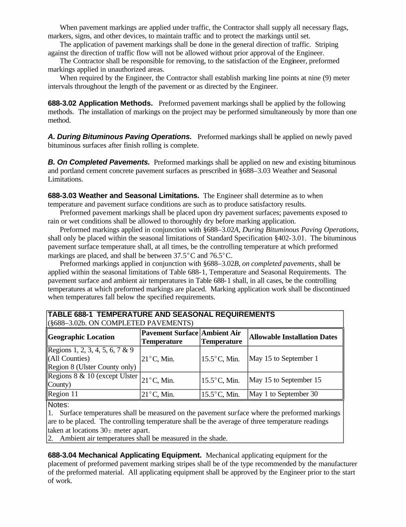
When pavement markings are applied under traffic, the Contractor shall supply all necessary flags, markers, signs, and other devices, to maintain traffic and to protect the markings until set. The application of pavement markings shall be done in the general direction of traffic. Striping against the direction of traffic flow will not be allowed without prior approval of the Engineer. The Contractor shall be responsible for removing, to the satisfaction of the Engineer, preformed markings applied in unauthorized areas. When required by the Engineer, the Contractor shall establish marking line points at nine (9) meter intervals throughout the length of the pavement or as directed by the Engineer. 688-3.02 Application Methods. Preformed pavement markings shall be applied by the following methods. The installation of markings on the project may be performed simultaneously by more than one method. A. During Bituminous Paving Operations. Preformed markings shall be applied on newly paved bituminous surfaces after finish rolling is complete. B. On Completed Pavements. Preformed markings shall be applied on new and existing bituminous and portland cement concrete pavement surfaces as prescribed in §688–3.03 Weather and Seasonal Limitations. 688-3.03 Weather and Seasonal Limitations. The Engineer shall determine as to when temperature and pavement surface conditions are such as to produce satisfactory results. Preformed pavement markings shall be placed upon dry pavement surfaces; pavements exposed to rain or wet conditions shall be allowed to thoroughly dry before marking application. Preformed markings applied in conjunction with §688–3.02A, During Bituminous Paving Operations, shall only be placed within the seasonal limitations of Standard Specification §402-3.01. The bituminous pavement surface temperature shall, at all times, be the controlling temperature at which preformed markings are placed, and shall be between 37.5EC and 76.5EC. Preformed markings applied in conjunction with §688–3.02B, on completed pavements, shall be applied within the seasonal limitations of Table 688-1, Temperature and Seasonal Requirements. The pavement surface and ambient air temperatures in Table 688-1 shall, in all cases, be the controlling temperatures at which preformed markings are placed. Marking application work shall be discontinued when temperatures fall below the specified requirements. TABLE 688-1 TEMPERATURE AND SEASONAL REQUIREMENTS (§688–3.02b. ON COMPLETED PAVEMENTS)
Geographic Location Pavement Surface Temperature
Ambient Air Temperature Allowable Installation Dates
Regions 1, 2, 3, 4, 5, 6, 7 & 9 (All Counties) Region 8 (Ulster County only)
21EC, Min. 15.5EC, Min. May 15 to September 1
Regions 8 & 10 (except Ulster County) 21EC, Min. 15.5EC, Min. May 15 to September 15
Region 11 21EC, Min. 15.5EC, Min. May 1 to September 30 Notes: 1. Surface temperatures shall be measured on the pavement surface where the preformed markings are to be placed. The controlling temperature shall be the average of three temperature readings taken at locations 30" meter apart. 2. Ambient air temperatures shall be measured in the shade. 688-3.04 Mechanical Applicating Equipment. Mechanical applicating equipment for the placement of preformed pavement marking stripes shall be of the type recommended by the manufacturer of the preformed material. All applicating equipment shall be approved by the Engineer prior to the start of work.
688-3.05 Rollers. Preformed markings applied in conjunction with §688–3.02a, during bituminous paving operations, shall be rolled into place with compaction equipment meeting the requirements of Standard Specification §402-3.04. Vibratory roller models shall operate in a 'static' mode. Preformed markings applied in conjunction with §688–3.02B., On Completed Pavements, shall be rolled into place using steel shell or pneumatic rubber–tired roller equipment approved by the Engineer. Steel wheel rollers shall weigh a minimum of 90 kg on each axle. Pneumatic rubber–tired rollers shall exert a minimum tire compression on the pavement of 195 Kpa. Hand rollers or rubber tired vehicles (e.g. pick–up truck) meeting the above requirements may be suitable for use. 688-3.06 Primer Requirements. When required, primer or adhesive shall be used for marking applications in accordance with the written recommendations of the manufacturer of the preformed marking material. Primer materials shall be placed at the application rate and by the application methods recommended by the manufacturer. When primer is applied, the area of application shall be at least the width or dimension, of the new preformed marking, plus twenty-five (25) millimeter on each side. 688-3.07 Surface Cleaning and Preparation of Pavement Surfaces. The Contractor shall be responsible for cleaning the pavement surface to the satisfaction of the Engineer. Surface cleaning and preparation work shall be performed only in the area of the preformed markings application. At the time of application, all pavement surfaces shall be free of oil, dirt, dust, grease and similar foreign materials. The cost of cleaning these contaminants shall be included in the bid price of this item. In addition, concrete curing compounds on new portland cement concrete surfaces and existing pavement markings on both concrete and bituminous pavement surfaces shall be removed and paid for under separate items. 688-3.08 Application of Preformed Reflectorized Pavement Markings. Unless otherwise approved by the Engineer, all longitudinal lines shall be applied using mechanical applicating equipment. Transverse and special marking patterns may be applied by hand or mechanical methods. Preformed marking operations shall not begin until after the pavement surface has been cleaned and prepared. Preformed stripes shall not be applied over longitudinal paving joints or over the point of transition between the pavement surface and adjoining shoulder. The placement of stripes in the area of transition shall be either on the pavement or on the shoulder, as directed by the Engineer. No roller shall operate in excess of 4.5 km/h. One roller pass shall be defined as one movement of the roller over any point of the preformed marking, in the direction of the marking application. A. Application During Bituminous Paving Operations. The application of preformed markings shall not begin until finish rolling of the new bituminous pavement is complete. At the time of marking application, the surface temperature of the new bituminous pavement shall be between 37.5EC and 76.5EC. The Contractor shall coordinate paving and preformed marking operations to conform with surface temperature requirements. Immediately after finish rolling is complete, the preformed marking shall be applied on the new bituminous surface. Traces of water or other residue from finish rolling operations shall first be removed. Immediately after its placement, the preformed marking shall be adhered to the warm pavement surface by rolling. Rollers shall make a minimum one pass, and operate in the same direction that the marking was applied. Diagonal, reverse or crosswise rolling will not be allowed. The minimum one pass may be increased by the Engineer if, in his opinion, the desired adherence is not obtained. B. Application on Completed Pavements. The application of preformed markings shall only be performed within the limitations of §688–3.03 Weather and Seasonal Limitations. If required by the manufacturer, primer and adhesive activators shall be applied and allowed to dry in accordance with the instructions of the manufacturer of the preformed material. The preformed marking shall be placed on the pavement surface and adhered by rolling. Rollers shall make a minimum of one pass, and operate in the same direction that the marking was applied. Diagonal,

reverse or crosswise rolling will not be allowed. The minimum one pass may be increased by the Engineer if, in his opinion, the desired adherence is not obtained. 688-4 METHOD OF MEASUREMENT. Pavement striping will be measured by meters along the centerline of the pavement stripe and will be based on a 100 mm wide stripe. The preformed pavement markings will be inspected during and following installation to determine conformance with this specification. In addition, they will be inspected following a performance period that will extend for 180 calendar days following both their installation and opening of the roadway to traffic. Within 15 consecutive calendar days after the end of the 180 day performance period, a final performance inspection will be made by the Engineer. If this inspection discloses any work, in whole or in part, as not being visibly intact and serviceable to the following extent, the Contractor shall completely repair or replace such work: A. Broken Line. 90 percent measured longitudinally of the total length of all broken lines in any 150 meter long pavement section. B. Dotted Line. 50 percent measured longitudinally of the total length of all dotted lines in any 30 meter long pavement section. C. Solid Line and Edge Line. 90 percent measured longitudinally of the total length of solid line or edge line in any 150 meter long pavement section. D. Channelizing Line, Stop Line, Crosswalk Lines, Clearance Line and Crossbars, Hatch Lines, Letters and Symbols. 90 percent by area of any individual line, letter or symbol. When required all repair or replacement work shall be performed in accordance with this specification and completed within 60 calendar days of the earliest allowable installation date as specified in Table 1, for that location. The Engineer shall determine the limits or quantity of preformed to be repaired or replaced. Upon completion of the final performance inspection, or after satisfactory completion of any necessary corrections, the Engineer will, within 10 calendar days, notify the Contractor in writing, of the date of such final performance inspection and release the Contractor from further performance responsibility. This delay in performance inspection and performance acceptance of preformed markings shall not delay acceptance of the entire project and final payment due if the Contractor provides the Department with a “Faithful Performance Bond,” and a “Labor and Material Bond” in the full amount of all preformed pavement marking items. These bonds shall conform to the requirements of §103–04 and shall be in full force and effect until final performance inspection and performance acceptance of the pavement markings. In addition the Contractor shall keep in force the various types of insurance as required by §107–06. Pavement striping on–going projects will be measured as the total of the striping applied, if after the final 180 day performance period, damage to the striping is not in excess of that specified (e.g. If 95% of the edgeline striping is intact in a 150 meter pavement section, the edgeline will be measured as the full 150 meters of applied marking. No deduction will be made for the damaged 5% (7.5 m) of striping). Measurement for striping with a plan width greater or less than the basic 100 mm as shown on the plans or as directed by the Engineer, will be made by the following method: Plan Width of Striping (millimeters) x Meters 100 (millimeters) No payment will be made for the number of meters of gaps between broken or dotted line segments. Letters and symbols will be measured by each unit applied. A unit will consist of one letter or one symbol. Example: “SCHOOL” would be measured as six units. Double and triple headed arrows will be measured as a single unit, but the “X” in railroad grade crossing markings (M.U.T.C.D. figure 263-33) will be measured by linear meter of 100 mm stripe.

688-5 BASIS OF PAYMENT. The accepted quantities of markings will be paid for at the contract unit price, which shall include the cost of furnishing all labor, materials and equipment to satisfactorily complete the work. The cost of cleaning pavement surfaces of oil, dirt, dust, grease and similar foreign materials shall be included in the price bid. The cost of removal of concrete curing compounds and existing pavement markings will be paid under separate items and are not included in this item. Payment will be made under: Item No. Item Pay Unit 688.01 M White Preformed Reflectorized Pavement Stripes Meter 688.02 M Yellow Preformed Reflectorized Pavement Stripes Meter 688.03 M White Preformed Reflectorized Pavement Letters Each 688.04 M White Preformed Reflectorized Pavement Symbols Each SECTION 689 (VACANT) SECTION 690 (VACANT) SECTION 691- EEO TRAINING REQUIREMENTS 691-1 DESCRIPTION . 691-1.01 General . This item of work shall consist of the meaningful and effective training of one or more minorities, women and disadvantaged persons leading to their qualification as journey-workers in one or more of the trades required in highway construction work. Disadvantaged means a person who is either a) a member of a family that receives public assistance, or b) a member of a family whose income during the previous six (6) months, on an annualized basis, was such that 1) the family would have qualified for public assistance, if it had applied for such assistance, or 2) it does not exceed the poverty level. The objective of these requirements is to provide training opportunities to minorities, women and disadvantaged persons for the following reasons: 1. To address the current under-representation of minorities, women and disadvantaged persons in the skilled trades of the highway construction industry, and; 2. To maintain a pool of qualified minorities, women and disadvantaged persons to compete for those journey-worker positions which are created in the natural course of events, as others leave the workforce. Accordingly, the contractor shall make every effort to hire and recruit minority, women and disadvantaged trainees/apprentices to the extent that such persons are available within a reasonable area of recruitment. This training commitment is not intended, and shall not be used, to discriminate against any applicant for training, whether a member of a minority group or not. 691-1.02 Authority . The statutory authority for the EEO and Training programs is contained in 23 U.S.C. 140(a), 23 CFR 230, 41 CFR 60-1 and 60-4, Executive Order 11246, New York State Executive Law Article 15-A and the rules promulgated thereunder. 691-2 MATERIALS - Not applicable. 691-3 CONSTRUCTION DETAILS . 691-3.01 General . Trainees and apprentices will be employed and offered meaningful and effective training opportunities on the contract. An apprentice is defined as an individual who is enrolled in an apprenticeship training program that is registered with the New York State Department of Labor. A trainee is defined as an individual who is enrolled in an On-the-Job Training (OJT) program that is approved by the New York State Department of Transportation. A list of such approved programs can be found in the On-the-Job Training and Apprenticeship Program Construction Catalogue which is available through the Department's Office of Equal Opportunity Development and Compliance. Meaningful and effective training is defined as occurring when the work of the contract provides a realistic and practical
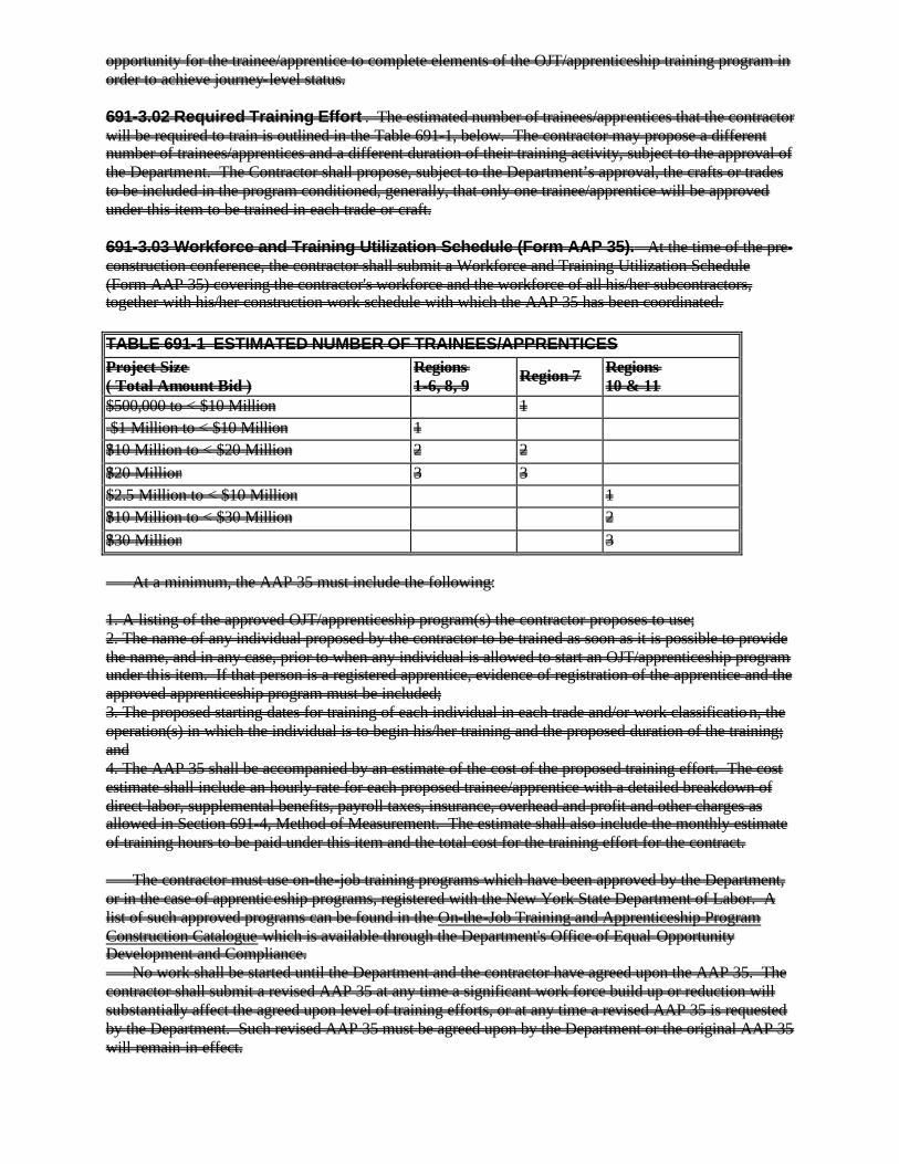
opportunity for the trainee/apprentice to complete elements of the OJT/apprenticeship training program in order to achieve journey-level status. 691-3.02 Required Training Effort . The estimated number of trainees/apprentices that the contractor will be required to train is outlined in the Table 691-1, below. The contractor may propose a different number of trainees/apprentices and a different duration of their training activity, subject to the approval of the Department. The Contractor shall propose, subject to the Department’s approval, the crafts or trades to be included in the program conditioned, generally, that only one trainee/apprentice will be approved under this item to be trained in each trade or craft. 691-3.03 Workforce and Training Utilization Schedule (Form AAP 35). At the time of the pre-construction conference, the contractor shall submit a Workforce and Training Utilization Schedule (Form AAP 35) covering the contractor's workforce and the workforce of all his/her subcontractors, together with his/her construction work schedule with which the AAP 35 has been coordinated. TABLE 691-1 ESTIMATED NUMBER OF TRAINEES/APPRENTICES Project Size ( Total Amount Bid )
Regions 1-6, 8, 9 Region 7 Regions
10 & 11 $500,000 to < $10 Million 1 $1 Million to < $10 Million 1 ?$10 Million to < $20 Million 2 2 ?$20 Million 3 3 $2.5 Million to < $10 Million 1 ?$10 Million to < $30 Million 2 ?$30 Million 3 At a minimum, the AAP 35 must include the following: 1. A listing of the approved OJT/apprenticeship program(s) the contractor proposes to use; 2. The name of any individual proposed by the contractor to be trained as soon as it is possible to provide the name, and in any case, prior to when any individual is allowed to start an OJT/apprenticeship program under this item. If that person is a registered apprentice, evidence of registration of the apprentice and the approved apprenticeship program must be included; 3. The proposed starting dates for training of each individual in each trade and/or work classification, the operation(s) in which the individual is to begin his/her training and the proposed duration of the training; and 4. The AAP 35 shall be accompanied by an estimate of the cost of the proposed training effort. The cost estimate shall include an hourly rate for each proposed trainee/apprentice with a detailed breakdown of direct labor, supplemental benefits, payroll taxes, insurance, overhead and profit and other charges as allowed in Section 691-4, Method of Measurement. The estimate shall also include the monthly estimate of training hours to be paid under this item and the total cost for the training effort for the contract. The contractor must use on-the-job training programs which have been approved by the Department, or in the case of apprenticeship programs, registered with the New York State Department of Labor. A list of such approved programs can be found in the On-the-Job Training and Apprenticeship Program Construction Catalogue which is available through the Department's Office of Equal Opportunity Development and Compliance. No work shall be started until the Department and the contractor have agreed upon the AAP 35. The contractor shall submit a revised AAP 35 at any time a significant work force build up or reduction will substantially affect the agreed upon level of training efforts, or at any time a revised AAP 35 is requested by the Department. Such revised AAP 35 must be agreed upon by the Department or the original AAP 35 will remain in effect.

691-3.04 Recruitment. The contractor shall decide who is hired as an apprentice or trainee. However, to satisfy the training requirements and to receive payment under this item, such apprentice or trainee must: 1. be a minority, woman or disadvantaged person; and 2. be enrolled in an on-the-job training or registered apprenticeship program approved by the Department; and 3. satisfy requirements under Section 691-3.05 Work History. In connection with the approval of the contractor's AAP 35, the contractor may request the assistance of the Department in recruiting and hiring acceptable persons under this item on Form AAP 17, Request for Personnel. The inability of the Department to assist the contractor will not diminish the contractor's obligation to comply with the requirements of this item. Prior to engaging in the recruitment of new trainees/apprentices, the contractor shall employ trainees/apprentices that are partially trained, if available, in order to facilitate completion of their on-the-job training/apprenticeship program. 691-3.05 Work History . The contractor shall not propose or use any person under this item if such person has successfully completed a training program providing journeyworker status in the same trade or work classification as will be used for training under this contract. Nor shall the contractor use or propose to use a person who has been gainfully employed, except under the special condition described in §691-4, as a journeyworker in that trade or work classification by virtue of informal on-the-job training or otherwise. The contractor must ascertain, before training a person and before requesting payment therefor under this item, whether the person qualifies under this item. The contractor must include appropriate questions on employee application forms and must check the personal references of an applicant for a position in order to ensure that the person is qualified for training under this item. The contractor's findings shall be maintained by the contractor, and shall be given to the Department upon request. No payment shall be made under this item for persons whose work history makes them ineligible for training in the trade or work classification. 691-3.06 Designated Training Coordinator and Trainer. The contractor will designate and identify to the Department a person (or persons) from his/her existing workforce as the Trainer and Training Coordinator for persons to be trained under this item. The Trainer and Training Coordinator shall be identified at the time of the preconstruction meeting. The designated Trainer shall: 1. be located on the job site generally on a daily basis; and 2. be responsible for the day-to-day supervision and training of persons under this item on the contract; and 3. be responsible for the preparation and submission of Form AAP 26, Monthly Training Progress Report, after consultation with designated trainees or apprentices. The designated Training Coordinator shall: 1. be knowledgeable about the contract and the OJT/apprenticeship programs to be used under this item; and 2. be responsible for ensuring on-the-job orientation for trainees or apprentices within their first days of employment; and 3. be responsible for ensuring meaningful and effective training for the duration of training. 691-3.07 Duration of Training. At the time a person reports to the contractor for training under this item, the Training Coordinator shall notify the EIC of this fact, and the EIC must be introduced to the trainee or apprentice at the earliest opportunity. After approval of a person to be trained under this item, the individual shall be employed as a trainee/apprentice in the designated trade in accordance with the currently approved AAP 35 to the extent that opportunities for training exist in the work of the contract in order to complete as much as possible of the approved OJT/apprenticeship program.

The contractor is expected to provide maximum opportunity to the trainee/apprentice to progress him/her to the completion of his/her program. In order to accomplish this, the contractor will monitor the trainee's/apprentice's progress, paying particular attention to completion of work processes or phases within the training program. When a work process or a phase of training is completed, the contractor is expected to rotate the trainee/apprentice to other work processes or phases of the OJT/apprenticeship program to the extent that such opportunities for such training exist. Should no such training opportunities exist, the trainee/apprentice can continue to work as long as there is work, provided, however, that no payments will be made under the Training Requirements item as a result of this work. Should a trainee/apprentice complete his/her training program during the life of the contract, the contractor is expected to retain the individual as a journey-level employee, provided there is work remaining on the project. Once the trainee/apprentice obtains journey-level status, the contractor will no longer be reimbursed for that individual under this item. 691-3.08 Trainee/Apprentice Termination. A trainee/apprentice may be terminated at any time during training for: excessive absenteeism; lack of punctuality; accident-proneness; lack of interest; poor attitude; and continued failure to conduct him/herself in a business-like manner. However, termination will not occur without: 1. documentation of counseling by the contractor's designated Trainer about the foregoing reason(s) for termination; and 2. documentation by the contractor's designated Trainer of efforts to resolve the foregoing problem; and 3. documentation of notification to the Engineer-in-Charge and Regional Compliance Specialist about the foregoing problem; and 4. written notification of intent to terminate to the Engineer-in-Charge and the Regional Compliance Specialist stating the reason(s) therefor; and 5. The Department will be afforded an opportunity to discuss the impending termination with the contractor in order to ensure that the contractor has complied with Steps 1 through 4 of this Subsection. 691-3.09 Monthly Training Progress Report. The contractor shall submit Form AAP 26, Monthly Training Progress Report, whenever a trainee or apprentice begins work on a contract and monthly thereafter as agreed upon at the pre-construction conference. Payment will be made under this item only for those trainees and apprentices and time periods for which a signed AAP 26 is received by the Department. 691-4 METHOD OF MEASUREMENT. The lump sum of money shown in the itemized proposal for this work is a nominal amount, but will be considered the price bid for the purpose of determining total amount bid, even though payment will be made for actual work performed. (At the time of the preconstruction conference, the Contractor will propose a training program for the Department’s approval, and a negotiated amount will be added to the contract by order-on-contract for the proposed training program.) The lump sum figure shown in the proposal is not to be altered in any manner by the bidder. Should the bidder alter the amount shown, the altered figure will be disregarded, and the original price will be used to determine the total amount bid for the contract. Payment will be made under this item for qualified trainees or apprentices required under this item not to exceed the lump sum amount in the contract as established through the order-on-contract mentioned above. Payment will be made only for those hours the trainee/apprentice is actually receiving training in the work elements included in his/her approved OJT/apprenticeship program. The amount of the actual payments will include: 1. Direct labor costs (actual hours worked multiplied by the basic hourly wage rate) plus supplemental benefit payments. Each class of labor shall be billed separately at actual payroll rates. 2. Payroll taxes, insurance payments and other such reasonable charges that are paid by the contractor pursuant to existing written agreements with employees and/or labor organizations. 3. Profit and Overhead. Profit and overhead shall be computed at 20% of items 1 plus 2 above. Profit and overhead will not be paid on the premium portion of overtime. If the trainee/apprentice is employed by a subcontractor, the contractor shall be paid the actual and reasonable cost of such subcontracted work

as outlined in items in 1 and 2 above, but profit and overhead shall be figured at 25% unless some other basis is approved by the Commissioner. Should a trainee/apprentice complete his/her training program during the life of the contract, the employee will be considered as having graduated to journey-level status. The contractor is expected to retain such graduated individuals as journey-level employees, provided there is work remaining on the project, however, once the trainee/apprentice obtains journey-level status, the contractor will no longer be reimbursed for that individual under this item. Should a work process or a phase of training be completed, and there are no other training phases or training work processes available that the trainee/apprentice may be rotated into, the trainee/apprentice can continue to work on the project, however, no payments will be made under the Training Requirements item for this work. Notwithstanding the provisions of §691-3.05, Work History, the trainee/apprentice’s continued employment under the circumstances just described will not make the trainee/apprentice ineligible for continued future training in the trade or work classification. One of the following methods, as determined by the Engineer, shall be used to determine the amount due the Contractor under this item: Method 1. Attached to each Monthly Training Progress Report, AAP 26, the Contractor shall attach a daily summary of hours of qualifying training (number of hours trained each day of the progress period). The total verified hours of training provided during the month will be multiplied by the agreed upon hourly rate submitted with the AAP 35 to determine the monthly payment due. Method 2. Attached to each Monthly Training Progress Report, AAP 26, the Contractor shall attach a daily summary of hours of qualifying training (number of hours trained each day of the progress period) and a Force Account Summation, MURK 13d, showing the actual cost of the training effort for the progress period. The amount shown on the force account summation will be used as the basis of payment for the progress period, subject to review and verification by the Engineer. If, after work has begun on the contract, the contractor is not meeting his/her equal employment opportunity goals (set elsewhere in the contract) and the contractor has demonstrated that good faith efforts were made to meet the goals with journey-workers, the contractor may be required to hire additional apprentices or trainees in order to meet the equal opportunity employment goals, but no payment will be made under this item for costs associated with those additional apprentices or trainees. In addition, materials and equipment costs, having been included in the other contract pay items of work, will not be included in the amount of actual payments made under this item. 691-5 BASIS OF PAYMENT. The lump sum for this work shown in the itemized proposal is a nominal sum only. It is recognized that it will not be sufficient for the intended purpose. Accordingly, a lump sum price is to be negotiated at the time of the preconstruction conference which will be sufficient to include the cost of labor trained as defined under this item. Off-site or related classroom training is not to be included in the lump sum amount negotiated for this item. Materials and equipment costs are to be included in the relevant contract items. Payment will be made for training properly completed and accounted for during the estimate period. Payment will be made under: Item No. Item Pay Unit Per Larry Brown 9/30/02 691.0101 Training Requirements Fixed Price Lump Sum Item suspended per EI 02-011 SECTIONS 692 THRU 696 (VACANT) SECTION 697 - INTERIM PAYMENT EI 02-024 697-1 DESCRIPTION

697-1.01 General. This section will provide for payment of work which has been authorized, and is pending addition to the Departments contract estimates payment system. Payments made under this section shall be reconciled through formal change orders, such that the final payment quantity of this section shall be a quantity of zero. 697-1.02 Eligible Work. Interim payments made under this section shall be limited to work which is within the scope of the contract. Such work shall be quantity variations of existing contract pay items or new contract pay items introduced as a result of minor adjustments in the details of the project. To be eligible, all work must be authorized in conformance with written procedures of the Department. This section shall not be used to make interim payment for work which is being progressed as disputed work or force account work. 697-1.03 Payment Computation and Reconciliation. Payments under this section shall be determined from the actual quantities and unit prices of eligible work which has been completed in conformance with applicable sections of the Specifications. The dollar value of payments shall be converted to a percentage payment of the fixed price lump sum shown in the proposal. The fixed price lump sum value shown in the proposal shall be the maximum eligible value of payment under this section, and shall not be altered by Order-on-contract. Once the contract has been amended to provide payment quantities under other pay items, payments shall be made under those items and payments made under this section shall be deleted. This section may again be used to make payment for further work, but at no time shall the total payments exceed the fixed price lump sum shown in the proposal. Prior to, or as part of the final payment submission, all payments made under this section must be transferred to appropriate contract work items, and payments provided under this section shall be deleted from the final contract payment submission. 697-2 MATERIALS. Materials shall meet the requirements of the Specification sections governing the work for which interim payment is being made under this section. 697-3 CONSTRUCTION DETAILS. Construction details shall conform with the requirements of the Specification sections governing the work for which interim payment is being made under this section. 697-4 METHOD OF MEASUREMENT. The fixed price lump sum shown in the proposal for this item shall be considered as the price bid, and shall not be altered in any manner. Should the amount shown be altered, the new figure shall be disregarded and the original price will be used to determine the total amount bid for the contract. Actual payments made under this section shall be computed as indicated in §697-1.03 Payment Computation and Reconciliation. Work for which interim payments are processed shall be measured in accordance with the Specification sections governing the actual work. 697-5 BASIS OF PAYMENT. Payments made under this section will be computed as indicated in §697-1.03 Payment Computation and Reconciliation, and shall not be altered in any manner as per §697-4. Work for which interim payments are processed shall be paid in accordance with the Specification sections governing the actual work. Payment will be made under: Item No. Item Pay Unit 697.01 M Interim Payment Fixed Price Lump Sum “SECTION 697 - FIELD CHANGE ORDER 697-1 DESCRIPTION 697-1.01 General. The Field Change Order (FCO) provides a contract contingency allowance for the timely payment of authorized additional work that is necessary to fulfill the intent of the plans and specifications.
697-1.02 Eligible Work. FCO payments shall be limited to work that is: (1) within the scope of the contract, (2) a quantity variation of existing contract pay items, or (3) a new contract pay item introduced as a result of minor field adjustments in the details of the project. All eligible items of work shall have a known unit price, determined in accordance with §109-05(A), Contract Item Changes or §109-05(B)1., New Item Charges, Agreed Prices. 697-2 MATERIALS. None Specified. 697-3 CONSTRUCTION DETAILS. None Specified. 697-4 METHOD OF MEASUREMENT. 697-4.01 Bid Price. The fixed price lump sum quantity shown in the proposal for this item will be considered as the price bid, and shall not be altered in any manner. Should the amount shown be altered, the new figure will be disregarded and the original bid price will be used to determine the total amount bid for the contract. 697-4.02 Payments. Work for which FCO payments are processed will be measured in accordance with the specifications governing the work. 697-5 BASIS OF PAYMENT. All work to be paid under the FCO item must be authorized in conformance with §104-03, Contingencies, Extra Work and Deductions. Disputed work, force account work, work associated with §104-10, Value Engineering Change Proposals, or payments for time related provisions are not eligible for FCO payment. FCO payments will be determined from the quantities and unit prices of eligible work that has been completed in conformance with applicable Specifications. Work for which FCO payments are processed will be paid in accordance with the specifications governing the work. Prior to processing the final agreement, the FCO payments will be reconciled through a final Order-on-Contract, such that the amount of FCO payments are converted to the corresponding quantities of the pertinent contract pay items. When payments are transferred to the appropriate items, the remaining amount of FCO funds will be deleted. Payment will be made under: Item No. Item Pay Unit 697.02 M Field Change Order (FCO) Fixed Price Lump Sum” EI 02-024 SECTION 697 - FIELD CHANGE ORDER 697-1 DESCRIPTION 697-1.01 General. The Field Change Order (FCO) provides a contract contingency allowance for the timely payment of authorized additional work that is necessary to fulfill the intent of the plans and specifications.

697-1.02 Eligible Work. FCO payments shall be limited to work that is: (1) within the scope of the contract, (2) a quantity variation of existing contract pay items, or (3) a new contract pay item introduced as a result of minor field adjustments in the details of the project. All eligible items of work shall have a known unit price, either through use of a contract bid price or through an Agreed Price. 697-2 MATERIALS. None Specified. 697-3 CONSTRUCTION DETAILS. None Specified. 697-4 METHOD OF MEASUREMENT. 697-4.01 Bid Price. The unit price shown in the proposal for this item will be considered as the price bid, and shall not be altered in any manner. Should the amount shown be altered, the new figure will be disregarded and the original bid price will be used to determine the total amount bid for the contract. 697-4.02 Payments. Work for which FCO payments are processed will be measured in accordance with the specifications governing the work. 697-5 BASIS OF PAYMENT. All work to be paid under the FCO item must be authorized in conformance with §104-03, Contingencies, Extra Work and Deductions. Disputed work, force account work, work associated with §104-10, Value Engineering Change Proposals, or payments for time related provisions are not eligible for FCO payment. FCO payments will be determined from the quantities and unit prices of eligible work that has been completed in conformance with applicable Specifications. Work for which FCO payments are processed will be paid in accordance with the specifications governing the work. Prior to processing the final agreement, the FCO payments will be reconciled through a final Order-on-Contract, such that the amount of FCO payments are converted to the corresponding quantities of the pertinent contract pay items. When payments are transferred to the appropriate items, the remaining amount of FCO funds will be deleted. Payment will be made under:
Item No. Item Pay Unit
697.0201 M Field Change Order (FCO) Dollars-Cents” EI 02-035 SECTION 698 - PRICE ADJUSTMENTS 698-1 DESCRIPTION 698-1.01 General. This section will provide for additional compensation to, or repayment by, the Contractor for increases or decreases in the price of asphalt or fuel throughout the life of the Contract. This adjustment will be computed within the prescribed conditions and in conformance with the written procedures of the Department. 698-1.02 Eligible Work. Price adjustments will be determined for eligible work listed in the proposal. No adjustment will be provided for any new work incorporated into the work by orders-on-contract or

those items paid for under force account or agreed unit prices. In addition, work ordered by the Engineer and performed by the Contractor at its own expense will not be eligible for price adjustment. 698-1.03 Method of Computation. The method of computations is given below: A. Asphalt Price Adjustment 1. The quantity of asphalt (metric tons) considered for adjustment will be determined by multiplying the quantity of eligible work placed by their conversion factors which are indicated in the Proposal asphalt price adjustment note. 2. Asphalt price adjustment will be based on the following formulae: a. When price increases: Price Adjustment = Quantity of Asphalt X (Average Posted Price - PGB Index Price - $10.00) b. When price decreases: Price Adjustment = Quantity of Asphalt X (Average Posted Price - PGB Index Price + $10.00) 3. The PGB Index Price and the Average Posted Price are defined as follows: a. Performance Graded Binder (PGB) Index Price. A fixed price per metric ton of asphalt. This price is used solely as a base from which to compute asphalt price adjustments. Its dollar amount is specified in the Proposal asphalt price adjustment note. b. Average Posted Price. The average FOB terminal price for unmodified PG 64-22 binder, without anti-stripping agent, will be determined by the Department monthly, based on prices of approved primary sources of performance graded binder. The asphalt price adjustment will be based solely on the price changes for asphalt as determined by the above formulas. No consideration will be given to the situation where an individual supplier's price exceeds the Average Posted Price, nor will any adjustment be made unless the Average Posted Price is either $10.00 greater than or less than the PGB Index Price. B. Fuel Price Adjustment. The fuel price adjustment shall be determined in accordance with the following prescribed conditions and methods of computation: 1. The quantity of fuel (Liters) considered for adjustment will be determined by multiplying the quantity of eligible work placed by their fuel usage factor (from the proposal fuel price adjustment note). 2. Fuel price adjustment will be based on the following formulae: a. When price increases: Fuel Adjustment = (Quantity of Fuel) X (Average Posted Price - Fuel Index Price - $0.03) b. When price decreases: Fuel Adjustment = (Quantity of Fuel) X (Average Posted Price - Fuel Index Price + $0.03) 3. The Fuel Index Price and the Average Posted Price are defined as follows:

a. Fuel Index Price. A fixed price per Liter of fuel. This price is used solely as a base from which to compute fuel price adjustments. Its dollar amount is specified in the Proposal fuel price adjustment note. b. Average Posted Price. The combined average FOB refinery or terminal price per Liter published for No. 2 fuel oil and unleaded gasoline in the cities of New York, Philadelphia, Detroit and Boston as determined by the Department on a monthly basis. The fuel adjustment will be based solely on the price changes for fuel as determined by the above formulae. No consideration will be given to the situation where an individual supplier's price exceeds the Average Posted Price, nor shall any adjustment be made unless the Average Posted Price is either $0.03 greater than or less than the Fuel Index Price. 698-2 MATERIALS. None specified. 698-3 CONSTRUCTION DETAILS. None specified. 698-4 METHOD OF MEASUREMENT. The lump sum shown in the proposal for these items shall be considered the price bid, although actual payment will be based on the work performed. The lump sum is not to be altered in any manner by the bidder. Should the amount shown be altered, the new figures will be disregarded and the original price will be used to determine the total amount bid for the contract. 698-5 BASIS OF PAYMENT. The actual price adjustments will be based on the methods of computation previously described in this specification. No adjustments, either positive or negative, will be made until payment of the final estimate, except that if the accumulated adjustment amount exceeds $5,000, adjustments will be included in progress estimates. The adjustment will be based on the quantity of eligible work placed and the Average Posted Price in effect at the time of placement. For the purpose of calculating price adjustments, the Average Posted Price will be updated about the twentieth of each month and will apply to eligible work performed on and after the first of the following month. If eligible fuel or asphalt calculated for an item is based on estimated quantities for that time, and an adjustment to the total item quantity is made in a subsequent or final estimate, an appropriate addition or deduction shall be made to the price adjustment previously calculated. The addition or deduction shall be based on the same Average Posted Price as was used to calculate the estimated item quantity which is being revised. If the placement dates of the adjusted quantity cannot be determined, the addition or deduction shall be based on the Average Posted Price in effect during the la st month in which any portion of the estimated item quantity was placed. If the contract completion date is extended without the assessment of engineering charges, price adjustments for items incorporated during such extensions shall be based on the appropriate updated Average Posted Price. If eligible items are placed after the scheduled contract completion date specified in the proposal and during which time there are assessed engineering charges and/or liquidated damages, the Average Posted Price used to compute price adjustments shall not exceed, but may be less than the Average Posted Price in effect on the last contract completion date without assessed engineering charges, or on the completion date of the last extension without assessed engineering charges, whichever is later. Payment will be made under: Item No. Item Pay Unit 698.01 M Asphalt Price Adjustment Fixed Price Lump Sum 698.02 M Fuel Price Adjustment Fixed Price Lump Sum SECTION 699 - MOBILIZATION 699-1 DESCRIPTION. Under this work the Contractor shall provide necessary bonds, insurance, and prefinancing and shall set up his necessary general plant, including shops, storage areas, office and such sanitary and other facilities as are required by local or state law or regulation.

699-2 MATERIALS. Such materials as required for mobilization and that are not to be part of the completed contract shall be as determined by the Contractor, except that they shall conform to any pertinent local or State Law, regulation or code. 699-3 CONSTRUCTION DETAILS. The work required to provide the above facilities and service for mobilization shall be done in a safe and workmanlike manner and shall conform with any pertinent local or State Law, regulation or code. Good housekeeping consistent with safety shall be maintained. 699-4 METHOD OF MEASUREMENT. Payment for mobilization will be made on a lump sum basis. 699-5 BASIS OF PAYMENT. The amount bid for mobilization shall not exceed four percent (4%) of the total contract bid price excluding the bid price for mobilization. Should the bidder exceed the foregoing four percent (4%), the Department will make the necessary adjustment to determine the total amount bid based on the arithmetically correct proposal. The amount bid shall include the furnishing and maintaining of services and facilities noted under §699-1 DESCRIPTION, to the extent and at the time the Contractor deems them necessary for his operations, consistent with the requirements of this work and the respective contract. The amount bid shall be payable to the Contractor with the first progress estimate made for other contract work, as set forth in §109-07, Payment of Estimates. Payment will be made under: Item No. Item Pay Unit 699.040001M Mobilization Lump Sum