Embed Size (px)
Citation preview

STANDARD SPECIFICATION
SS-GVW-505
Sewage Pump Station Design Manual
Sewage Pump Station Design Manual
Version No. 4.0 Page 2 of 26 DOC16/6265
TABLE OF CONTENTS 1. GENERAL ...................................................................................................................................... 3 2. OVER VIEW .................................................................................................................................... 3 3. PUMP STATION SITE SELECTION ................................................................................................. 4 4. PUMP WELL AND VALVE PIT CONFIGURATION ............................................................................ 5 4.1 General .................................................................................................................................................. 5 4.2 Personnel Access .................................................................................................................................. 6 4.3 Pump Well Ventilation and Odour Control .......................................................................................... 6 5. PIPEWORK .................................................................................................................................... 6 5.1 General .................................................................................................................................................. 6 5.2 Discharge Pipework .............................................................................................................................. 7 6. PUMPSETS AND RISING MAIN ..................................................................................................... 8 6.1 Flowmeters ............................................................................................................................................ 9 7. PUMP INSTALLATION .................................................................................................................... 9 7.1 Guide Rails ............................................................................................................................................ 9 7.2 Guide Rail Fixing .................................................................................................................................... 9 7.3 Lifting Chain ........................................................................................................................................... 9 7.4 Pump ID Plate ........................................................................................................................................ 9 8. VALVES ....................................................................................................................................... 10 8.1 General ................................................................................................................................................ 10 8.2 Sluice Valves ....................................................................................................................................... 10 8.3 Non Return Valve ................................................................................................................................ 10 8.4 Knife Gate Valve .................................................................................................................................. 11 8.5 Valve Pit Drain Check Valve ............................................................................................................... 11 8.6 Air Valve ............................................................................................................................................... 11 9. ELECTRICAL AND TELEMETRY .................................................................................................. 11 9.1 Electricity Supply ................................................................................................................................. 11 9.2 Electrical and Electronic Equipment ................................................................................................. 11 9.3 Ancillary ................................................................................................................................................ 15 9.4 Installation - Cables Conduits and Junction Boxes .......................................................................... 15 9.5 Switchboard Cabinet .......................................................................................................................... 15 9.6 Telemetry Backup ............................................................................................................................... 16 9.7 Fail Safe ............................................................................................................................................... 16 10. PUMP WELL CONSTRUCTION .................................................................................................... 16 10.1 Design Criteria ..................................................................................................................................... 16 11. WATER SUPPLY .......................................................................................................................... 17 12. PUMP STATION DOCUMENTATION ............................................................................................ 17 13. STANDARD DRAWINGS ............................................................................................................. 18 14. APPENDICES .............................................................................................................................. 18 15. DOCUMENT CONTROL ............................................................................................................... 18 APPENDIX A: TYPICAL SEWER PUMP STATION - INPUT / OUTPUT SCHEDULE ................................. 19 APPENDIX B: SCADA SYSTEM – CABINET LAYOUT ............................................................................. 20 APPENDIX C: SCADA SYSTEM – RTU & RADIO SCHEMATIC ............................................................... 21 APPENDIX D: SCADA SYSTEM – POWER SUPPLY SCHEMATIC .......................................................... 22 APPENDIX E: SCADA SYSTEM – TERMINAL STRIP DIAGRAM ............................................................ 23 APPENDIX F: SEWAGE PUMP STATION – STANDARD SWITCHBOARD LAYOUT (SHEET 1) ............... 24 SEWAGE PUMP STATION – STANDARD SWITCHBOARD LAYOUT (SHEET 2) ..................................... 25 SEWAGE PUMP STATION – STANDARD SWITCHBOARD LAYOUT (SHEET 3) ..................................... 26
Sewage Pump Station Design Manual
Version No. 4.0 Page 3 of 26 DOC16/6265
1. GENERAL
The Corporation reserves the right to accept an alternative proposal which performs equal to, or better than, the design performance criteria contained in this document, other than where specifically identified as being a requirement by the Corporation.
Alternative proposals are to be identified and approved in writing by the Corporation’s Technical Customer Services Coordinator prior to their adoption.
This Design Manual is based on Corporation drawing No. STD/06 and whilst the specific configuration of this drawing is not a requirement, its design performance criteria along with the performance provisions made in this design manual are a Corporation requirement.
All materials and equipment are to have minimum 12 months warranty.
All brackets, access ladders, lifting chains, chemical set anchor bolts, bolts, nuts and washers are to be stainless steel.
All stainless steel is to be grade 316 or better.
Mild steel items to be hot dipped galvanised in accordance with A.S. 1650
Fixing of holding brackets to pump station wall shall be carried out in accordance with manufacturer’s instructions and the relevant Australian Standards.
Provisions under the Sewer Network Odour Management Strategy
In accordance with the Sewer Network Odour Management Strategy adopted by the Board in October 2011, provisions in relation to odour management are to be incorporated for all new sewage pump station installations. For further details regarding these provisions, contacting Goulburn Valley Water is highly recommended.
The review of this documentation should be completed in 2016, where the design manual will incorporate the provisions under the Sewer Network Odour Management Strategy.
2. OVER VIEW
The pump station shall meet the following design criteria:
The pump well structure is to have a 100 year design life;
The pump station shall be underground and the structure shall be capable of withstanding forces from ground pressure. The design must be stable under all conditions of flotation and the base must be adequate to support the pumps and other equipment;
The pump station structure shall be capable of withstanding live loading which may reasonably be expected to be placed on the structure for the duration of its life ie traffic loading;
Be a minimum internal diameter of 2.0m;
Be equipped with 2 No. complete and identical pumpsets;
Be integrated with the Corporation’s telemetry system;
Sewage Pump Station Design Manual
Version No. 4.0 Page 4 of 26 DOC16/6265
Be designed with minimisation of long term maintenance and operation costs in mind;
Meet current environment protection guidelines and regulations;
Have two complete pumpsets and associated pipe work with one on duty one on standby, but capable of operating simultaneously and both capable of pumping raw sewage;
Cleaning and removal of equipment to be achievable without entering the pump station;
Be provided with access ladder;
Be fitted with a permanent tubular handrail system around the opening to the pump well;
Be capable of commanding all proposed and future proposed catchment areas;
Have sufficient storage capacity to hold 3 hour peak dry weather flow;
Disperse odours into the atmosphere via induct and educt ventilation system;
Minimise noise pollution;
Have vehicular traffic bollards at not greater than 1.8m centres fixed to the perimeter of top slab; and
Include a Magnetic Flowmeter on the discharge rising main for all industrial and large catchment pump stations.
3. PUMP STATION SITE SELECTION
The following criteria shall be met when selecting the pump station site:
Located to avoid gravity sewers being laid at a depth of greater than 6 metres in private property;
Located to avoid associated rising main traversing private property;
Located within a reserve designated in favour of Goulburn Valley Region Water Corporation road reserve or on a property which is owned by Goulburn Valley Water for the life of the pumping station. The pump station site area is to be a minimum of 10 metres by 8 metres;
The site must be accessible by vehicles by means of an all weather road. The layout of the pumping station and other features must ensure that the available space for maintenance purposes is maximised. A water supply is necessary for wash down purposes. A hard standing area must also be provided adjacent to the pumping station;
Top of slab to be above 1 in 100 year flood level and located 150mm above finished natural surface level;
Not located along an existing or proposed pedestrian/cyclist or vehicle traffic alignment;
Minimise aesthetic issues for neighbouring properties and the general public;
Not encumbered by existing or proposed overhead power lines;
Sewage Pump Station Design Manual
Version No. 4.0 Page 5 of 26 DOC16/6265
Has metered reticulated water supply with a pressure reducing valve;
Has electricity supply capable of meeting pump station loading within Electricity supply regulations for both Amperage and Voltage;
Soil conditions are suitable or may be made suitable; and
Minimise length of rising main.
4. PUMP WELL AND VALVE PIT CONFIGURATION
4.1 General
The pump well shall meet the following design criteria;
Minimum internal diameter of 2.0m;
Capable of accommodating two submersible pumps, associated pipe work, electrical wiring and access equipment and personnel access room;
There shall be an external valve pit adjacent to the pump well structure;
Free head room space of two (2) metres shall be provided for the full floor area of the pump well;
A 50 mm uPVC pipe shall be provided to discharge wastewater from the valve pit into the pump well with a 50mm ERV Duckbill Check Valve. The floor of the valve pit is to be sloped towards the discharge pipe at a grade of not less than 1 in 30 as detailed on Corporation’s Drawing STD/6;
Pump well covers providing access to the manhole and/or valve pit shall have minimum clear access of 900mm x 750mm. The designer is to ensure pumps can pass through pump well opening;
Two hinged safety mesh covers, comprising hot dipped galvanised F81 mesh, are to be installed at the top of the well with a 30mm gap between the mesh covers when closed. They are to be rated to support the weight of a single person and will provide a secure work platform for inspection and washing down of the pump well. The support frame is to be secured into the well with stainless steel bolts.
Covers are to be two part aluminium lids with hasps and staple for installation of padlock or similar covers approved by the Corporation’s Technical Customer Services Coordinator. The covers shall be of sufficient size and orientation to facilitate installation and removal of equipment and plant as well as personnel access to the pump well and valve pit. Where covers are to carry vehicular or similar traffic loading gatic covers are to be installed. Under these circumstances bollards are not required. Covers are to be gas tight and lockable via clasp and staple;
All metalwork in the pump well and valve chamber must be corrosion protected or of metal type which is not adversely effected by raw sewage i.e. grade 316 stainless steel;
The pump well floor is to be shaped to avoid retention of waste water and material entering the pump well. Where this is achieved through placement of mass
Sewage Pump Station Design Manual
Version No. 4.0 Page 6 of 26 DOC16/6265
concrete, the concrete is to be placed at a slope of 1 in 1 and positioned to minimise corner area without impeding the removal of pump well equipment.
An acceptable means of achieving the 100 year pump station design life criteria as required under section 2 of this design manual is the use of Humes Class 4 Reinforced Concrete Pipe sections with sulphate resistant concrete plastiline insert inner liner and lifting lugs located on spigot and to allow plastic liner over lays to point downwards.
4.2 Personnel Access
The pump well is a confined space and shall be treated as such under Occupational Health and Safety regulations.
Access to the valve pit and pump well shall be facilitated by a stainless steel ladder fabricated and installed in accordance with standard drawing No. S/7 and S/8, fitted with telescopic handrails on the ladder or a retractable ladder.
A permanent handrail system is also to be installed around the opening to the pump well, as per dwg STD/9. This is to be fabricated from a tubular handrail system in hot dipped galvanised mild steel. It is to include two removable sections to enable access to the pump well as required. The other features of the handrail include that if it obstructs the opening of the lids, that approved latches or chains are to be fitted to secure the lid while opened. The handrail is to have a maximum spacing between posts of 2m and is to be between 900mm-1100mm high with a mid rail fitted.
Bollards, comprising 1.50m high circular hollow section, are to be fixed with suitable fasteners to each corner and centrally to the top of the slab to prevent vehicles driving over the top of the slab.
4.3 Pump Well Ventilation and Odour Control
The pump well shall be vented by means of a 12 metre high educt vent as detailed on Corporation drawings STD/6 and S/9 (Corporation requirement). Note, the height of the educt vent may vary subject to site specific conditions and will require approval from Goulburn Valley Water.
The vent stack is to be designed for wind loading in accordance with AS1170.
A cast iron ashdown vent is to be provided as an induct vent to allow the entry of air into the pump well. (Corporation requirement).
The vent stack is to be installed in a location where it does not impede access and opening of doors, lids on the pump well or the control cabinet. Further, the location for the vent stack must comply with local Council, electricity agency and other service agency requirements, that may be affected by the installation.
The vent stack is to have a sealable opening to allow for a temporary installation of an odour logger.
5. PIPEWORK
5.1 General
Pipework shall be designed in accordance with the following requirements;

Sewage Pump Station Design Manual
Version No. 4.0 Page 7 of 26 DOC16/6265
Ductile Iron pipework and fittings are to be used in the pump well, valve pit and between the last manhole and the pump well and as shown on Corporation drawing No. STD/6;
All Ductile Iron pipework carrying waste water is to be Epoxy lined. Application of Epoxy lining is to be carried out by manufacture of pipe and fittings at their factory. An approved epoxy material supply and application system is to be used, such as Dulon ‘Armourcote’ 412 applied by accredited applicator and have dry film thickness of 500 micrometres applied through two coats in accordance with manufacturer’s instructions, or similar two pack epoxy protective coating as approved by the Goulburn Valley Region Water Corporation.
Polyethylene pipework, PE80 PN12.5 will be accepted as an alternative for DIEL pipework, only after prior approval from the Corporation. No PE pipe is allowed to be cast through any concrete walls, and as such flanged distance pieces are to be used to provide the transfer through any concrete.
5.2 Discharge Pipework
Pipework shall be supported at not greater than
1.5 metre intervals for DIEL and
1.0 metre intervals for PE
and at all changes in direction;
Velocity in Pipework is not to be less than 1m/s or exceed 2.5 m/s;
Pipework is not to be of a greater diameter than rising main diameter;
Where support of Pipework is provided by brackets, the brackets are to be manufactured from 50mm wide by 5mm thick stainless steel fixed to the pump well structure using M12 stainless steel bolts fastened by either chemical set anchor bolts installed in accordance with manufacturers instructions and specifications or by the use of ferrules. Ferrules are to be installed either prior to pouring of caisson or post fitted by means of penetrations through the wall of the pump well with stainless steel nuts and washers;
All joints must be flanged and provided with 3mm thick full face neoprene gaskets and a hardness of Durometer Shore ‘A’ 50 5 to prevent joint leakage;
All flanges and gaskets must be drilled off centre in accordance with Table C of AS 2129;
A Ductile Iron tee with 100mm flange and blank flange plate is to be installed within the valve pit, positioned on discharge side of one of the non-return valves and aligned in a vertical upwards position to allow for the temporary connection of a by-pass pump which would draw independently from the pump well and discharge into the rising main at the valve pit. It is identified as a emergency pump out tee;
All bolts, nuts and washers must be stainless steel, Grade 316. Dismantling joints or equivalent must be provided, eg Uniflange;
All pipework connections are to be flange joints within the pump well and valve pit;

Sewage Pump Station Design Manual
Version No. 4.0 Page 8 of 26 DOC16/6265
Where uniflanges are used, bolts are to be stainless steel of 12mm shaft diameter; and
Magnetic flowmeters are to be installed immediately down stream of the valve pit on the discharge pipework, within the pump station site area, as per manufacturers’ instructions.
6. PUMPSETS AND RISING MAIN
There shall be 2 complete pump sets. The Pumps shall be Flygt of type CP or similar as approved by the Corporation for use in wastewater application containing solids and fibre and mounted on pedestal for removal from the well by Stainless steel lifting chain without personnel having to enter the pump well.
Pumps shall be the submersible type capable of passing a 75mm diameter sphere through the impeller and driven by a non-overloading direct coupled motor.
The pump capacity of a pumping station shall be capable of pumping at full catchment development discharge:
Temporary Pumping Station Q = 4 x mean dry weather flow
Permanent Pumping Station Q = 6 x mean dry weather flow
or otherwise as directed
Network modelling indicates that dry weather flows range from 150 to 250 litres per person per day which translates to 450 to 750 litres per household per day. For new residential development flows a figure of 600 litres per lot per day is acceptable. Independent allowances are required for schools, shops, etc, which form part of the development.
The cut in/cut out levels must be set to give maximum of 10 pump starts per hour per pump. The pumps and pedestals shall be coated in accordance with the standard specifications.
Pump curves plotted with the rising main discharge characteristic curves shall be provided when pump station design plans are lodged.
The friction loss of the rising main shall be calculated using formulas, charts or table from one of the following assessment techniques.
Colebrook White
Hazen Williams Formula
Manning Formula
Computations shall be provided of calculation of rising main friction losses including valves, bends and other items which cause friction loss when pump station design is lodged with the Corporation for checking.
Regard shall be made to selecting a pump which is capable of meeting both initial development discharge requirements and full catchment development with consideration to pump efficiency through changing impeller size.
Sewage Pump Station Design Manual
Version No. 4.0 Page 9 of 26 DOC16/6265
Pump sets shall have moisture detection equipment which when moisture is sensed shall isolate that pumpset and signal a pumpset fault via the telemetry system. The motor thermistor overload protectors shall be in accordance with AS1023.3. A seal probe relay is an acceptable mechanism for detecting the intrusion of moisture into the pump well.
The pump stations discharge pipe work shall be taken as 150mm below the sewer invert.
6.1 Flowmeters
Magnetic flowmeters are to be installed on the discharge rising mains from all industrial and large catchment pump stations and are to be installed within the pump station site.
The location of the flowmeter and all cabling is to be included in the as constructed information with a location plan fixed to the inside of the control cabinet.
7. PUMP INSTALLATION
7.1 Guide Rails
Guide rails are to be fabricated from two number 50mm dia. x 3.2mm thick circular hollow sections internally and externally hot dipped galvanised coated in accordance with AS 1650. Alternatively grade 316 stainless steel tubing of the same dimensions may be used.
7.2 Guide Rail Fixing
Guide rail fixing is to be to the pump well access entrance, pump well floor and to have stainless steel anti-spread brackets located at not greater than 2 metre centres, refer Corporation’s Drawing No. STD/6.
7.3 Lifting Chain
Lifting chains to be Stainless Steel, a minimum link size of 10mm and capable of lifting 200 kg without exceeding yield stress. Chain is to be attached to pump lifting hooks by means of a stainless steel shackle meeting A.S 2741 Standards. The other end of chain shall be placed on a Stainless Steel chain hook at pump well entrance in similar position as pump guide rail holding bracket.
7.4 Pump ID Plate
An engraved ID plate will be fixed to inside of the pump opening in the well identifying the pump number below, which coincide with the pump control and SCADA system, such as “PUMP 1”.

Sewage Pump Station Design Manual
Version No. 4.0 Page 10 of 26 DOC16/6265
8. VALVES
8.1 General
The following valve types are to be supplied and installed to the pump well and associated works.
1 No. isolation valve of same diameter as sewer main is to be located on the sewer main either in the manhole immediately prior to the pump station or in the pump station. The valve is to be a sluice valve or where space is insufficient to accommodate a sluice valve, a knife gate valve shall be installed.
2 No. non return valves of swing check type with cast iron casing and bronze disc.
2 No. sluice valves as rising main isolation valves with cast iron casing and bronze wedge.
1 No. flap valve to be installed at discharge from valve pit to pump well
8.2 Sluice Valves
All sluice valves shall conform to the following criteria:
meet the requirements of AS 2638-1991
shall be a minimum class 14;
shall be clockwise closure with non-rising spindles;
shall be flange type drilled off centre to Table C in accordance with AS 2129.
terminate with a stem cap and shall be key operated, unless specified otherwise;
have internal and external protective coating using an approved thermal-bonded coating in accordance with A.S./NZS 4158.1 Polymeric coatings for water industry purposes, Part 1.
where specified, handwheels shall be manufactured from ductile cast iron. They shall be sized so as to unseat and seat the valves under all likely service conditions using a rim pull force on the handwheel of less than 40 Newton. Handwheels shall be painted with 2 coats of epoxy enamel.
8.3 Non Return Valve
All non return valves shall confirm to the following:
Non return valve are to be swing check type
Minimum class 14
Manufacture in accordance with A.S. 3578 Cast Iron non-return valves, general purpose.
Ductile iron valves may be used subject to internal and external protective coating being an approved thermal-bonded coating in accordance with A.S./NZS 4158.1 Polymeric coatings for water industry purposes, Part .

Sewage Pump Station Design Manual
Version No. 4.0 Page 11 of 26 DOC16/6265
8.4 Knife Gate Valve
Knife gate valve to be Bi-directional (Rovalve Fig 77F or approved equivalent) with non-rising stem, Grade 316 S.S. Component and Grade 316 S.S. extension spindle extension spindle to be supported by Grade 316 S.S. support brackets at 1500mm maximum spacing. Valve to be supplied complete with valve key cover box and all nuts, bolts and washers and gaskets for insertion between Table C flanges, drilled off centre.
8.5 Valve Pit Drain Check Valve
A 50mm Dia ERV Duckbill Check Valve is to be fitted to the 50mm uPVC drain from the valve pit.
8.6 Air Valve
Air valves are to be located at all ‘high points’ along the rising main except at rising main discharge point.GVW accepts only stainless steel combined air release valves for sewage from AVFI – Model ARV-3-N.
9. ELECTRICAL AND TELEMETRY
9.1 Electricity Supply
9.1.1 General
The switchboard shall be provided with 3 phase mains power supply to adequately operate pumps, pump controls, telemetry equipment and two 10 amp general power outlets.
The consultant shall arrange with the Electricity Supply Company for connection of electrical supply including the meeting of associated costs as part of the projects. The Corporation shall only meet the costs associated with electricity consumption due to the operation of the pump station i.e. not connection or upgrading of electrical supply to the pump station site.
9.1.2 Operation of Pump Station from Alternative Supply
The pump station shall be designed operate from an alternative on site power supply via one standard connection should mains power fail for an extended period. During the commissioning of the pump station an alternative electrical supply shall be provided and all the pump station electrical consuming equipment shall be operated. The consultant shall ensure that all electrical equipment operates within normal parameters from the alternative power supply.
The alternative electrical supply connection shall be installed to the switchboard cabinet without requiring the cabinet door to remain open.
9.2 Electrical and Electronic Equipment
The following electrical and electronic equipment and materials shall be supplied and installed. A polarity switch shall be installed as part of the pump station’s construction. The polarity shall be capable of reversing the polarity of the alternative electrical supply to avoid the possibility of pumps running backwards. In addition, the polarity switch is to prevent pumps operating in the reverse direction should the polarity of the alternative supply be incompatible with the pump stations wiring configuration.

Sewage Pump Station Design Manual
Version No. 4.0 Page 12 of 26 DOC16/6265
9.2.1 Meters
The following meters:
Eastern Energy/Powercor (SECV) meter;
3 phase switching Amp meters (2 No.);
5 digit hours run meter (2 No.);
A magnetic flowmeter with 4-20 mAmp output; and
A power meter (Schneider PowerLogic PM710MG)
are required to be installed.
9.2.2 Pump Station Controls
Each pump is to be fitted with the following manual switch configuration.
On
The pump will operate independently of automatic control system from the station controller.
Off
Pump has been isolated from electrical control
The pump station level control system shall consist of a Vegawell 72 pressure transducer 0-1 bar with a Vegadis 12 Hart scaling unit to provide a 4-20mA output across the specified transducer range.
The output of this pressure transducer shall control the start / stop levels of the pumps via a MANN Industries model PMX410 controller . The controller shall also provide an isolated 4-20mA output which is required to be terminated to Analog Input No. 1 to the Telemetry Terminal Strip. Telemetry remote control operation requires a continuous 4-20mA value of the station / well capacity. Refer to Telemetry Input and Output schedule for details.
A dedicated High Level Float shall be installed and wired to Input No. 13 of the terminal strip. Power Supply to this float shall be via the 12 volt power supply which provides for battery backup for well level high alarming during periods of AC power supply outage/s.
A Local / Remote Duty selector switch shall be installed to provide a separation of station operation. This switch shall be arranged to provide Control Circuit Functions for:-
In the Local Duty Select Auto Run Mode - Local "calling" of pumps shall be initiated by a panel mounted MANN controller, Model PMX10A, having calling levels fixed at the Site, and
In the Remote Telemetry Duty Select mode - the local calling of pumps shall be DISABLED, and the Telemetry Unit calling ENABLED. In this Station operating mode the Telemetry Interface will provide station level operating Set points, and pumps duty selection (Cycle Duty, 1 - 2 Duty or 2 - 1 duty, etc.)
Sewage Pump Station Design Manual
Version No. 4.0 Page 13 of 26 DOC16/6265
i) Auto / Local Control
Primary Station Auto Local control operation shall be set up in accordance with pre set levels; refer to TABLE 1, Pump control for details. Such operating levels shall be pre programmed into the MANN controller to provide for Duty / Standby operation of the pumps. A Pump duty selector switch shall be installed to provide for duty 1 - 2, or 2 - 1 operating mode.
Auto Cycling of Pump units is not required for Local Auto Running.
Emergency Local Control Auto Running shall be initiated by means of a High Level Float. Such running and control shall be confined to LOCAL AUTO run.
The emergency high level float control shall remain DISABLED during:-
pump OFF isolation, and
telemetry REMOTE control selection
TABLE 1
Pump Control Level/Setting
duty cut-in level set at 150mm below the incoming sewer invert level
cut-out level 50mm above pump cavitation level
low level alarm at the cavitation level of the pumpset
standby cut-in level set at 150mm above the duty cut-in level
high level alarm / float set at 300mm above standby cut-in level
emergency level alarm set at 500mm above standby cut-in level
Pump control is to be set for not greater than 6 hours detention period.
The pump controller is to switch off pump(s) under the following conditions:
Low water level;
Thermostatic overload is tripped;
Where pump is manually selected to off “position”.
Where the emergency high level alarm is activated, and the pump station is in local auto duty, the emergency high level float shall trigger a station run independent of any controller set points. Such emergency type station operation shall require that both pumps run for an adjustable period of time. The emergency type pump station control shall be arranged so that it is repetitive until the station fault is rectified.

Sewage Pump Station Design Manual
Version No. 4.0 Page 14 of 26 DOC16/6265
ii) Auto / Remote Control
Station operating levels will be in accordance with levels pre programmed into the Telemetry Processor. In this operating mode the station will rely on the telemetry processor for control and monitoring. Changes to various station control setpoints will be accessed via the GVW Regional SCADA System. Such access is not confined to but includes the following:-
level control set points
pumps duty selection 1 - 2, 2 - 1, Cycle
Station Operation Inhibit
individual pump sets Inhibit
Alarming set points for excessive starts
Alarming set points for excessive hours run
off peak tariff control starts
In the REMOTE Telemetry mode of station operation any "local" calling shall remain disabled.
Emergency high level well station running is NOT required for this mode of operation.
9.2.3 Radio Telemetry Equipment
Radio telemetry equipment to convey signals and data to include:
RTU (Remote Telemetry Unit and Radio)
Signal wiring to a telemetry terminal strip
Antenna and signal cable.
Radio Telemetry Equipment is to be compatible with the Corporation's existing telemetry system. Specific approval must me obtained from the Corporation's Technical Customer Services Coordinator where other than existing equipment type is proposed to be installed.
The Corporation’s existing telemetry system is the DNP III Protocol.
Radio Telemetry equipment is to be capable of transmitting and receiving information from the station's signals and controls.
Provision is to be made to isolate telemetry equipment during normal operation of the pump station, including when the pump station is operating from an alternative power supply.
The station's telemetry interface is to be compatible with the Corporation's existing telemetry system and be capable of monitoring and control for the range of signals shown in Appendix A: Typical Sewage Pump Station – Input/Output Schedule.
Reference is also made to Appendix B: Typical Telemetry Terminal Strip and Appendix C: Telemetry Diagram
Note: The type of RTU to be installed may differ from site to site, it is recommended Goulburn Valley Water be contacted regarding the type of RTU required.

Sewage Pump Station Design Manual
Version No. 4.0 Page 15 of 26 DOC16/6265
9.3 Ancillary
The switch board cabinet shall be fitted with 2 No. 10 amp general power outlets which can be accessed without requiring access to the internal of the cabinet, The power outlets are to be suitable for external use i.e. all weather.
9.4 Installation - Cables Conduits and Junction Boxes
Cabling is to be positioned in conduits as shown on Corporation drawing No. STD/6.
Cabling is to be laid to equipment in conduits which meets the Electricity Supply Corporation’s requirements. Sufficient length of cabling is to be provided to facilitate easy access to and removal of pump well equipment. Cabling is to be suitable for operation in submersed raw sewage conditions.
Conduits are to be either heavy duty uPVC or stainless steel and sealed via expanding foam application or similar as approved by the Corporation, to all locations where pump well gas may vent to the outside the pump well or valve pit.
Junction boxes are to be water tight, positioned to allow access to pump well and removal of pumping equipment.
9.5 Switchboard Cabinet
Gas tight electrical socket connections supplying power to pump sets are to be positioned near the top of pump well access ladder and suspended by a stainless steel hook. The switchboard cabinet to be constructed from 3mm thick, marine grade aluminium with sufficient space to accommodate the following equipment:
Supply Company meter
Amp meters
Hour run meters
Switchgear
Control circuits including pump control system and circuit breakers
Telemetry equipment
Alternative power supply wiring
Electric wiring so as not to present a ‘birds nest’
The cabinet is to be free standing, weather proof and powder coat finish with Dulux (Colour - Beige) or equivalent as approved by Goulburn Valley Region Water Corporation
The cabinet is not to exceed 1500mm in height above top of slab.
The cabinet is to be lockable by means CL001 standard Lock.
The cabinet door is to swing open 180 deg and be capable of being fixed at a 90deg opened position.
A Fluorescent, door switch operated, light is to be fitted to the interior of the cabinet.
A door open switch is to be placed complete with Intruder Alarm Contacts to Digital Input No. 11 of the Terminal Strip.

Sewage Pump Station Design Manual
Version No. 4.0 Page 16 of 26 DOC16/6265
The cabinet position is to be specified on detailed design plans for approval by the Corporation.
A metal pocket is to be provided in the cabinet capable of holding details on the pump station including design plans, electrical layout plans, pump operational manuals, A4 cleaning maintenance and repair ‘exercise’ book.
9.6 Telemetry Backup
The Telemetry backup system is to be capable of operating for a period of not less than 24 hours without mains or temporary electrical supply.
9.7 Fail Safe
The telemetry system shall convey a breach in normal operating status condition via fail safe logic for the following conditions: Power supply failure
10. PUMP WELL CONSTRUCTION
Pump wells shall be purpose built concrete structures. Alternative materials have to have prior approval from the Corporation.
The pump well shall have clear 2m head room space for the area of the pump stations floor ie no valve pit obstruction to head room.
Concrete pump wells may be either cast insitu or prefabricated.
Standard drainage pipes (Class 2) shall not be accepted as adequate.
The following pre-cast structure is approved by the Corporation for use as pump station caissons.
CSR Humes 1.8m internal diameter class 4(Z) slip ring concrete sewerage pipe with sulphate resistant additive, centrally placed reinforcement and plastiline insert inner liner. Minimum cover 44mm over reinforcing and calcareous aggregate.
The following are Corporation approved pump well structures with regard to structural integrity only.
Corporation standard drawing STD/6.
Aquatec standard pump station with amendments meeting this design manual
Where a concrete pump well structure is being used, the wall penetrations are to be filled with Mega Epoxy 2 pack by Vivacity Engineering or similar as approved by the Corporation. Wall penetrations are to be cored and not broken out to prevent stress cracks from being created
10.1 Design Criteria
Pumpwell structure is to be designed in accordance with AS 3600 with concrete strength of F’c = 32 Mpa
Structural design work shall be considered by the Corporation where supplied with certified structural computations and drawings prepared by a registered building practitioner, copy of certificate of registration is to be provided when design plans are lodged for checking.
Sewage Pump Station Design Manual
Version No. 4.0 Page 17 of 26 DOC16/6265
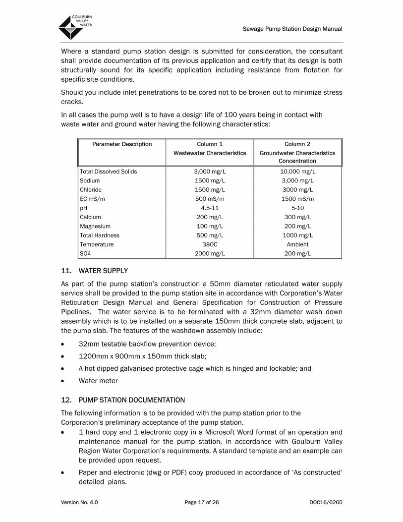
Where a standard pump station design is submitted for consideration, the consultant shall provide documentation of its previous application and certify that its design is both structurally sound for its specific application including resistance from flotation for specific site conditions.
Should you include inlet penetrations to be cored not to be broken out to minimize stress cracks.
In all cases the pump well is to have a design life of 100 years being in contact with waste water and ground water having the following characteristics:
Parameter Description Column 1
Wastewater Characteristics
Column 2
Groundwater Characteristics Concentration
Total Dissolved Solids 3,000 mg/L 10,000 mg/L
Sodium 1500 mg/L 3,000 mg/L
Chloride 1500 mg/L 3000 mg/L
EC mS/m 500 mS/m 1500 mS/m
pH 4.5-11 5-10
Calcium 200 mg/L 300 mg/L
Magnesium 100 mg/L 200 mg/L
Total Hardness 500 mg/L 1000 mg/L
Temperature 38OC Ambient
SO4 2000 mg/L 200 mg/L
11. WATER SUPPLY
As part of the pump station’s construction a 50mm diameter reticulated water supply service shall be provided to the pump station site in accordance with Corporation’s Water Reticulation Design Manual and General Specification for Construction of Pressure Pipelines. The water service is to be terminated with a 32mm diameter wash down assembly which is to be installed on a separate 150mm thick concrete slab, adjacent to the pump slab. The features of the washdown assembly include:
32mm testable backflow prevention device;
1200mm x 900mm x 150mm thick slab;
A hot dipped galvanised protective cage which is hinged and lockable; and
Water meter
12. PUMP STATION DOCUMENTATION
The following information is to be provided with the pump station prior to the Corporation’s preliminary acceptance of the pump station. 1 hard copy and 1 electronic copy in a Microsoft Word format of an operation and
maintenance manual for the pump station, in accordance with Goulburn Valley Region Water Corporation’s requirements. A standard template and an example can be provided upon request.
Paper and electronic (dwg or PDF) copy produced in accordance of ‘As constructed’ detailed plans.
Sewage Pump Station Design Manual
Version No. 4.0 Page 18 of 26 DOC16/6265
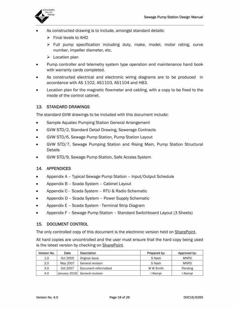
As constructed drawing is to include, amongst standard details:
Final levels to AHD
Full pump specification including duty, make, model, motor rating, curve number, impeller diameter, etc.
Location plan
Pump controller and telemetry system type operation and maintenance hand book with warranty cards completed.
As constructed electrical and electronic wiring diagrams are to be produced in accordance with AS 1102, AS1103, AS1104 and HB3.
Location plan for the magnetic flowmeter and cabling, with a copy to be fixed to the inside of the control cabinet.
13. STANDARD DRAWINGS
The standard GVW drawings to be included with this document include:
Sample Aquatec Pumping Station General Arrangement
GVW STD/2, Standard Detail Drawing, Sewerage Contracts
GVW STD/6, Sewage Pump Station, Pump Station Layout
GVW STD/7, Sewage Pumping Station and Rising Main, Pump Station Structural Details
GVW STD/9, Sewage Pump Station, Safe Access System
14. APPENDICES
Appendix A – Typical Sewage Pump Station – Input/Output Schedule
Appendix B – Scada System – Cabinet Layout
Appendix C - Scada System – RTU & Radio Schematic
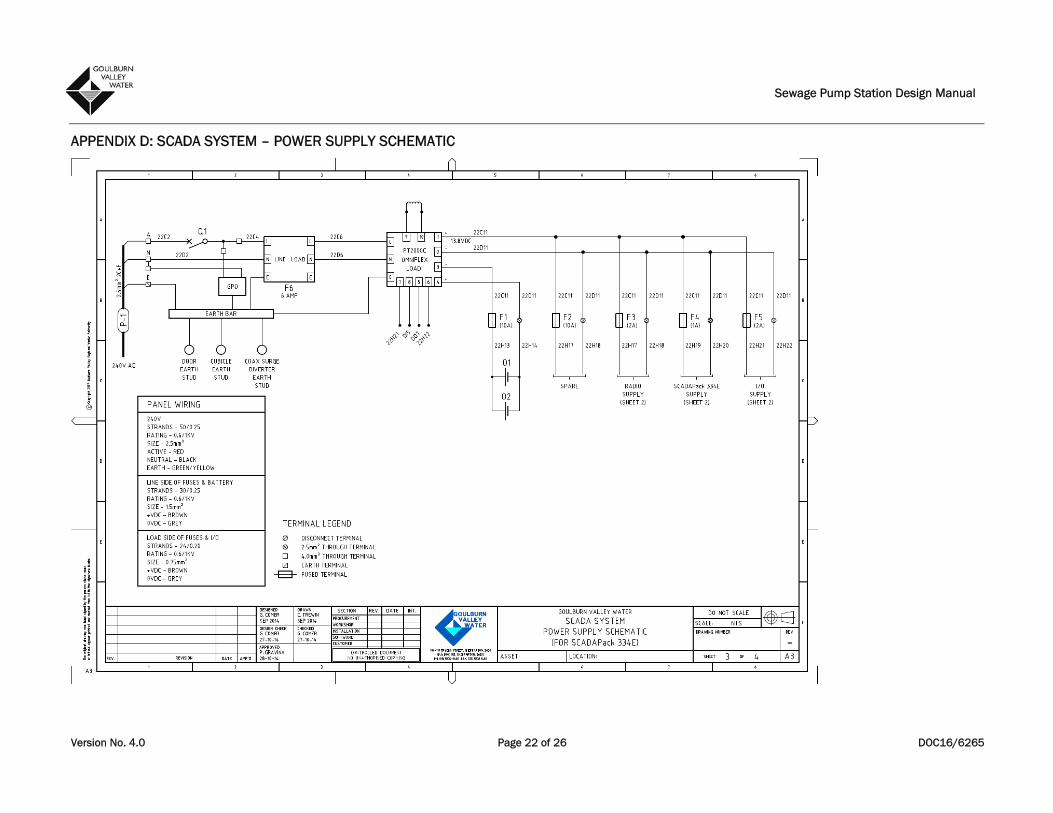
Appendix D – Scada System – Power Supply Schematic
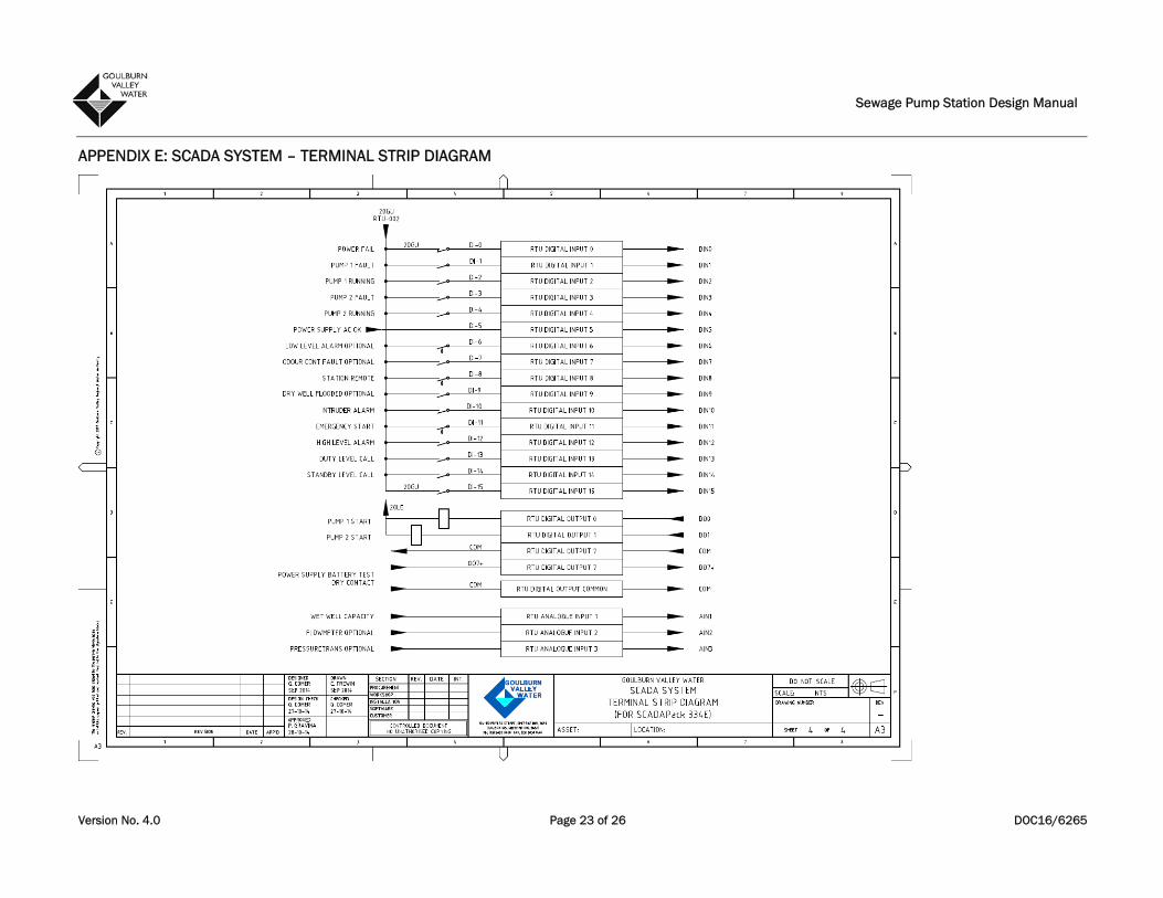
Appendix E – Scada System - Terminal Strip Diagram
Appendix F – Sewage Pump Station – Standard Switchboard Layout (3 Sheets)
15. DOCUMENT CONTROL
The only controlled copy of this document is the electronic version held on SharePoint.
All hard copies are uncontrolled and the user must ensure that the hard copy being used is the latest version by checking on SharePoint.
Version No. Date Description Prepared by: Approved by:
1.0 Oct 2005 Original issue S Nash MNPD
2.0 May 2007 General revision S Nash MNPD
3.0 Oct 2007 Document reformatted W W Smith Pending
4.0 January 2016 General revision I Alampi I Alampi

Sewage Pump Station Design Manual
Version No. 4.0 Page 19 of 26 DOC16/6265
APPENDIX A: TYPICAL SEWER PUMP STATION - INPUT / OUTPUT SCHEDULE
334 No. Point Description / Type Pump / Structure / Tank
Point Type Point Status Message By Telemetry System
DIGITAL INPUTS
0 1 2 3 4 5 6 7 8 9
10 11 12 13 14 15
AC Power Fail Pump 1 Fault (Common Pump Faults) Pump 1 Running Pump 2 Fault (Common Pump Faults) Pump 2 Running RTU Power Supply Fail Wet Well Level Low Odour Control Fault Station Control Mode Dry Well Level (Dry Well Sites Only) Intruder Alarm Emergency Pump Operation Wet Well Level High Duty Level Called Standby Level Called Generator (334)
Alarm Alarm Status Alarm Status Alarm Alarm Status Alarm Alarm Status Alarm Status Status Status
Normal / Fault Normal / Fault Running/ Stopped Normal/ Fault Running / Stopped Normal / Fail Normal/ Running/ Fault Local/ Remote Normal / Flooded Normal / Intruder Normal / Operating Normal / High Normal / Called Normal/ Called Running/ Stop
DIGITAL OUTPUTS
0 1 2 3 4 5 6 7
Start Pump 1 Start Pump 2 Cut In Level Override ( Remote Start) Spare #4 Spare #5 Spare #6 Battery Test Output Spare #7
Control Control Control
(Controlled by Telemetry) (Controlled by Telemetry) (Controlled by Telemetry) (Controlled by Telemetry)
ANALOGUE INPUTS
0 1 2 3
Wet Well Capacity Station Outflow Rate (Where Metered) Retic. Pressure Spare
Analog Analog Analog Analog
4 - 20 mA ( 0 - 100%) 4 - 20 mA ( 0 - 100 L/s) 4 – 20mA 4 – 20mA
COUNT 0 Rain Counter Input (Option) Digital Pulse Notes:
1. A Local / Remote Duty Selector Switch shall be installed to provide a separation of Station Operation. This switch shall be wired to provide Control Circuit functions for:- a. In the Local Duty Select Auto Run Mode - Local calling of pumps shall be initiated by a
panel mounted Weidmuller, Model PMX420, having calling levels fixed at the Site, and b. In the Remote Duty Select Mode - the Local calling shall be DISABLED, and the Telemetry
Unit calling i. ENABLED. ii. In This mode the Telemetry Interface will provide Station Level operating Set Points,
and Pumps Duty iii. Selection ( Cycle Duty, 1 - 2 Duty or 2 - 1 Duty, etc. )
2. A Vegawell 52 pressure Transducer is required for "Well Level Source" at the Station. The Analogue Loop from the transducer shall be terminated to Local Control Equipment, and to Analogue Input 1 of the Terminal Strip. (Refer to Appendix E for details of Terminal Strip Interface arrangement.)
3. All Pump Station Control Circuits shall be of 24v AC Type. 4. Terminal Strip terminations shall be Voltage Free Contacts. 5. Control by Telemetry Output ( as applicable) shall be switched through a wire link, and slave Relay.
Such switching shall be low voltage ( 24v AC) , Typical. 6. All other configuration of the Station shall be in accordance with respective sections of the
Specification.

Sewage Pump Station Design Manual
Version No. 4.0 Page 20 of 26 DOC16/6265
APPENDIX B: SCADA SYSTEM – CABINET LAYOUT

Sewage Pump Station Design Manual
Version No. 4.0 Page 21 of 26 DOC16/6265
APPENDIX C: SCADA SYSTEM – RTU & RADIO SCHEMATIC
Sewage Pump Station Design Manual
Version No. 4.0 Page 22 of 26 DOC16/6265
APPENDIX D: SCADA SYSTEM – POWER SUPPLY SCHEMATIC
Sewage Pump Station Design Manual
Version No. 4.0 Page 23 of 26 DOC16/6265
APPENDIX E: SCADA SYSTEM – TERMINAL STRIP DIAGRAM

Sewage Pump Station Design Manual
Version No. 4.0 Page 24 of 26 DOC16/6265
APPENDIX F: SEWAGE PUMP STATION – STANDARD SWITCHBOARD LAYOUT (SHEET 1)

Sewage Pump Station Design Manual
Version No. 4.0 Page 25 of 26 DOC16/6265
SEWAGE PUMP STATION – STANDARD SWITCHBOARD LAYOUT (SHEET 2)
Sewage Pump Station Design Manual
Version No. 4.0 Page 26 of 26 DOC16/6265
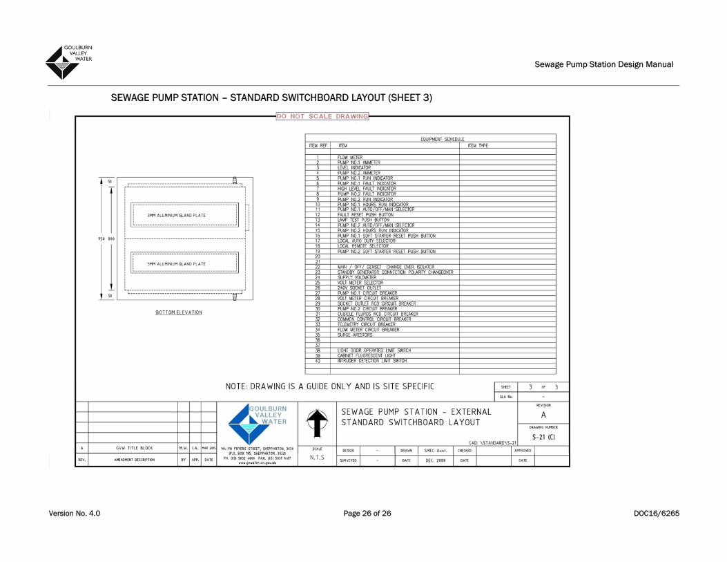
SEWAGE PUMP STATION – STANDARD SWITCHBOARD LAYOUT (SHEET 3)