Embed Size (px)
Citation preview

38
http://en.pisco.co.jp
StandardSeries
MiniSeries
StainlessSeries
ChemicalSeries
PPSeries
EGSeries
Anti-spatter& Brass Series
Die TemperatureControl
MinimalSeries
Stop FittingSeries
RotarySeries
Twist-ProofFitting
Block andConnector
Coupling
ColorCap
FITTING
TUB
EVA
LVECONTROLLER
MAKE-TO-ORDERPRODUCTS
Push-In Fitting Type for Pneumatic PipingTube Fitting Standard Series
●Push-in fitting for General Pneumatic Piping.
●Redesigned 17 models, realized weight saving.(PC,�PCF,�POC,�PM,�PMF,�PL,�PLL,�PLH,�PLF,�PVX,�PAX,�PB,�PD,�PX,�PRX,�PKD,�PKVD)
●Rotatable Resin Body after Installation.
●Wide Variety of Products.
●Centralized Piping.Triple�type�(PKD,�PKG,�PKJ)�and�twin�triple�type�(PKVD,�PKVG)�are�compact�designed�to�achieve�centralized�piping.
●Optional Selection of Clean-Room Package and Clean-wash Package.
Fitting SeriesTube Fitting
StandardSeries
39
FITT
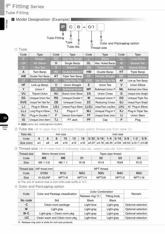
ING ■ Model Designation (Example)
CP 6 01
② Tube dia.�(※�In�case�that�②�indicates�thread,�select�thread�size�from�table�③)
③ Thread size�(※�In�case�that�③�indicates�tube�dia.,�select�tube�dia.�from�table②)Thread size Metric thread (mm) Taper pipe thread
Code M5 M6 01 02 03 04Size M5×0.8 M6×1 R1/8 R1/4 R3/8 R1/2
Code Type Code Type Code Type Code Type
C Straight OC Inner Hex. Straight L Elbow LL Long Elbow
LH 45° Elbow H Single Banjo OL Hex. Holed Banjo B Branch Tee
D Run Tee X Branch Y VX Tripod Elbow AX Branch Elbow
A Twin Banjo RX Double Branch Y HW Double Banjo HT Triple Banjo
AW Double Twin Banjo AT Triple Twin Banjo CF Female Straight MF Bulkhead Female Straight
LF Female Elbow KD Triple Run Tee KVD Twin Triple Run Tee AF Link-up Twin Banjo
HF Link-up Banjo U Union Straight E Union Tee V Union Elbow
Y Union Y M Bulkhead Union MP Bulkhead Union P ML Bulkhead Union Elbow
VU Tripod Union AU Branch Union Elbow ZA Union Cross G Unequal Union Straight
EG Unequal Union Tee RG Unequal Double Y W Unequal Union Y KG Unequal Triple Tee
KVG Unequal Twin Triple Tee ZB Unequal Cross ZC Reducing Cross GJ Unequal Plug-in Straight
LJ Plug-in Elbow LGJ Unequal Plug-in Elbow LLGJ Unequal Plug-in Long Elbow LHJ 45° Plug-in Elbow
LLJ Long Plug-in Elbow YJ Plug-in Y WJ Unequal Plug-in Y KJ Plug-in Triple Tee
RJ Plug-in Double Y F Extension Screw Adaptor FF Unequal Screw Union IJ Union Stem
IG Unequal Union Stem TJ PT Jack PF Cap P Plug
※���������parts�are�redesigned�models.
① Type
Tube dia. mm size inch size
Code 4 6 8 10 12 16 5/32 3/16 1/4 5/16 3/8 1/2 5/8Size (mm) ø4 ø6 ø8 ø10 ø12 ø16 ø3.97 ø4.76 ø6.35 ø7.94 ø9.53 ø12.7 ø15.88
Tube Fitting ①Type
③Thread size
②Tube dia.
Thread size UNF thread (mm) NPT thread
Code U10U N1U N2U N3U N4U N0USize 10-32UNF NPT1/8 NPT1/4 NPT3/8 NPT1/2 NPT1/16
※�The�unit�of�wrench�size�is�inch�(the�code�suffix�is�“U”).�
④Color and Packaging option
④ Color and Packaging option
Code Color and Package classificationColor Combination
RemarkRelease ring(※) Fitting body
No code Std. Black Black
-C Clean-room package Light-blue Light-gray Optional selection
W Light-gray Light-gray Light-gray Optional selection
W-C Light-gray + Clean-room pkg. Light-gray Light-gray Optional selection
-UC Clean-wash and Clean-room pkg. Light-blue Light-gray Optional selection
※ . Release-ring color is white for inch-size products.
40
http://en.pisco.co.jp
StandardSeries
MiniSeries
StainlessSeries
ChemicalSeries
PPSeries
EGSeries
Anti-spatter& Brass Series
Die TemperatureControl
MinimalSeries
Stop FittingSeries
RotarySeries
Twist-ProofFitting
Block andConnector
Coupling
ColorCap
FITTING
TUBE
VALVE
CONTROLLERMAKE-TO-ORDERPRODUCTS
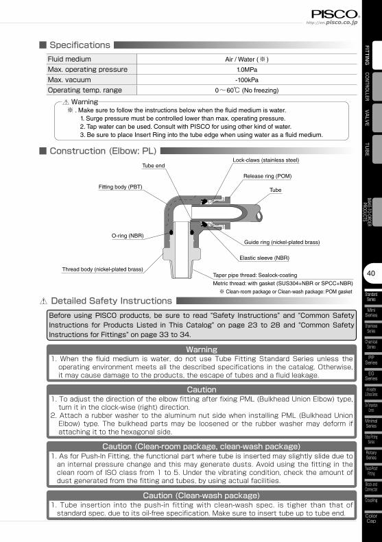
■ SpecificationsFluid medium Air / Water (※ )
Max. operating pressure 1.0MPa
Max. vacuum -100kPa
Operating temp. range 0~60℃ (No freezing)
■ Construction (Elbow: PL)
※ . Make sure to follow the instructions below when the fluid medium is water. 1. Surge pressure must be controlled lower than max. operating pressure. 2. Tap water can be used. Consult with PISCO for using other kind of water. 3. Be sure to place Insert Ring into the tube edge when using water as a fluid medium.
Warning
Elastic sleeve (NBR)
Taper pipe thread: Sealock-coating
Metric thread: with gasket (SUS304+NBR or SPCC+NBR)
※ Clean-room package or Clean-wash package: POM gasket
Tube
Release ring (POM)
Lock-claws (stainless steel)
O-ring (NBR)
Tube end
Fitting body (PBT)
Thread body (nickel-plated brass)
Guide ring (nickel-plated brass)
Detailed Safety InstructionsBefore using PISCO products, be sure to read “Safety Instructions” and “Common Safety Instructions for Products Listed in This Catalog” on page 23 to 28 and “Common Safety Instructions for Fittings” on page 33 to 34.
Warning1.��When� the� fluid�medium� is�water,� do� not� use�Tube�Fitting�Standard�Series� unless� the�operating�environment�meets�all�the�described�specifications�in�the�catalog.�Otherwise,�it�may�cause�damage�to�the�products,�the�escape�of�tubes�and�a�fluid�leakage.
Caution1.��To�adjust�the�direction�of�the�elbow�fitting�after�fixing�PML�(Bulkhead�Union�Elbow)�type,�turn�it�in�the�clock-wise�(right)�direction.
2.��Attach�a�rubber�washer�to�the�aluminum�nut�side�when�installing�PML�(Bulkhead�Union�Elbow)� type.� The�bulkhead�parts�may�be� loosened�or� the� rubber�washer�may�deform� if�attaching�it�to�the�hexagonal�side.
Caution (Clean-room package, clean-wash package)1.��As�for�Push-In�Fitting,�the�functional�part�where�tube�is�inserted�may�slightly�slide�due�to�an�internal�pressure�change�and�this�may�generate�dusts.�Avoid�using�the�fitting�in�the�clean�room�of�ISO�class�from�1�to�5.�Under�the�vibrating�condition,�check�the�amount�of�dust�generated�from�the�fitting�and�tubes,�by�using�actual�facilities.
Caution (Clean-wash package)1.�� Tube� insertion� into� the� push-in� fitting�with� clean-wash�spec.� is� tigher� than� that� of�standard�spec.�due�to�its�oil-free�specification.�Make�sure�to�insert�tube�up�to�tube�end.

Fitting SeriesTube Fitting
StandardSeries
41
FITTING ■ Standard Size List
Connection: Thread ⇔ Tube (P44~P68)
Type Page Thread sizeTube O.D.
4 6 8 10 12 16 5/32 3/16 1/4 5/16 3/8 1/2 5/8PC Straight P.44 M5×0.8 ◎ ◎ ◎ ◎ ◎
M6×1 ◎ ◎R1/8 ◎ ◎ ◎ ◎ ◎ ◎ ◎ ◎ ◎R1/4 ◎ ◎ ◎ ◎ ◎ ◎ ◎ ◎ ◎ ◎ ◎R3/8 ◎ ◎ ◎ ◎ ◎ ◎ ◎ ◎ ◎ ◎R1/2 ◎ ◎ ◎ ◎ ◎ ◎
POC Inner Hex. Straight P.45 M5×0.8 ◎ ◎M6×1 ◎ ◎R1/8 ◎ ◎ ◎ ◎ ◎ ◎R1/4 ◎ ◎ ◎ ◎ ◎ ◎ ◎R3/8 ◎ ◎ ◎ ◎ ◎ ◎R1/2 ◎ ◎ ◎ ◎
PCF Female Straight P.46 M5×0.8 ◎ ◎Rc1/8 ◎ ◎ ◎ ◎ ◎ ◎ ◎Rc1/4 ◎ ◎ ◎ ◎ ◎ ◎ ◎ ◎ ◎ ◎ ◎Rc3/8 ◎ ◎ ◎ ◎ ◎ ◎ ◎ ◎ ◎Rc1/2 ◎ ◎ ◎
PMF Bulkhead Female Straight P.47 Rc1/8 ◎ ◎ ◎Rc1/4 ◎ ◎ ◎ ◎ ◎Rc3/8 ◎ ◎ ◎ ◎ ◎Rc1/2 ◎ ◎
PL Elbow P.48 M5×0.8 ◎ ◎ ◎ ◎ ◎M6×1 ◎ ◎R1/8 ◎ ◎ ◎ ◎ ◎ ◎ ◎ ◎ ◎R1/4 ◎ ◎ ◎ ◎ ◎ ◎ ◎ ◎ ◎ ◎ ◎R3/8 ◎ ◎ ◎ ◎ ● ◎ ◎ ◎ ◎ ●R1/2 ◎ ◎ ● ◎ ◎ ●
PLL Long Elbow P.50 M5×0.8 ◎ ◎R1/8 ◎ ◎ ◎ ◎ ◎ ◎ ◎ ◎ ◎R1/4 ◎ ◎ ◎ ◎ ◎ ◎ ◎ ◎ ◎ ◎ ◎R3/8 ◎ ◎ ◎ ◎ ● ◎ ◎ ◎ ◎R1/2 ◎ ◎ ● ◎ ◎
PLH 45°Elbow P.51 R1/8 ◎ ◎R1/4 ◎ ◎ ◎R3/8 ◎ ◎ ◎ ●R1/2 ◎ ◎ ●
POL Hex. Holed Banjo P.51 M5×0.8 ●R1/8 ● ●R1/4 ● ● ●R3/8 ● ● ●R1/2 ●
PLF Female Elbow P.52 M5×0.8 ◎ ◎ ◎ ◎ ◎M6×1 ◎ ◎Rc1/8 ◎ ◎ ◎ ◎ ◎ ◎ ◎Rc1/4 ◎ ◎ ◎ ◎ ◎ ◎ ◎ ◎ ◎ ◎ ◎Rc3/8 ◎ ◎ ◎ ◎ ◎ ◎ ◎ ◎ ◎Rc1/2 ◎ ◎ ◎ ◎
PAX Branch Elbow P.53 M5×0.8 ◎ ◎PVX Tripod Elbow P.54 M6×1 ◎ ◎
R1/8 ◎ ◎ ◎ ◎R1/4 ◎ ◎ ◎ ◎ ◎R3/8 ◎ ◎ ◎ ◎R1/2 ◎ ◎
Type Page Thread sizeTube O.D.
4 6 8 10 12 16 5/32 3/16 1/4 5/16 3/8 1/2 5/8PH Single Banjo P.55 M5×0.8 ● ● ● ● ●
M6×1 ● ●R1/8 ● ● ● ● ● ● ●R1/4 ● ● ● ● ● ● ●R3/8 ● ● ● ● ● ● ●R1/2 ● ● ●
PHW Double Banjo P.57 R1/8 ● ● ● ●PHT Triple Banjo P.58 R1/4 ● ● ● ● ● ● ● ●
R3/8 ● ● ● ● ● ● ● ●R1/2 ● ● ● ● ●
PA Twin Banjo P.59 M5×0.8 ●R1/8 ●R1/4 ●R3/8 ●R1/2 ●
PAW Double Twin Banjo P.60 R1/8 ● ● ● ●PAT Triple Twin Banjo P.61 R1/4 ● ● ● ● ● ● ● ●
R3/8 ● ● ● ● ● ● ● ●R1/2 ● ● ● ● ●
PB Branch Tee P.62 M5×0.8 ◎ ◎PD Run Tee P.64 M6×1 ◎ ◎
R1/8 ◎ ◎ ◎ ◎ ◎ ◎ ◎ ◎ ◎R1/4 ◎ ◎ ◎ ◎ ◎ ◎ ◎ ◎ ◎ ◎ ◎R3/8 ◎ ◎ ◎ ◎ ● ◎ ◎ ◎ ◎R1/2 ◎ ◎ ● ◎ ◎
PX Branch Y P.66 M5×0.8 ◎ ◎M6×1 ◎ ◎R1/8 ◎ ◎ ◎ ◎ ◎ ◎ ◎ ◎ ◎R1/4 ◎ ◎ ◎ ◎ ◎ ◎ ◎ ◎ ◎ ◎ ◎R3/8 ◎ ◎ ◎ ◎ ● ◎ ◎ ◎ ◎R1/2 ◎ ◎ ● ◎ ◎
PRX Double Branch Y P.67 R1/8 ◎ ◎R1/4 ◎
Type Page Thread sizeTube O.D.1
Tube O.D.24 6 8
PKD Triple Run Tee P.67 R1/8 ◎ 6R1/4 ◎ ◎ 8R3/8 ◎ 10
PKVD Twin Triple Run Tee P.68 R1/4 ◎ ◎ 8
R3/8◎ ◎ 8
◎ ◎ 10R1/2 ◎ ◎ 10
Type Page Thread sizeTube dia.(mm)
4 6 8 10PTJ PT Jack P.87 M5×0.8 ● ●
R1/8 ● ● ●R1/4 ● ●R3/8 ● ●
Type Page Thread sizeThread size2
M5×0.8 Rc1/8 Rc1/4 Rc3/8 Rc1/2PF Extension Screw Adaptor P.88 M5×0.8 ● ●
R1/8 ● ● ● ●R1/4 ● ● ● ● ●R3/8 ● ● ● ●R1/2 ●
PFF Unequal Screw Union P.89 Rc1/8 ●Rc1/4 ●Rc3/8 ● ●Rc1/2 ● ●
Type Page Thread sizeTube O.D.
Thread size24 6 8 10 12 5/32 3/16 1/4 5/16 3/8 1/2
PHF Link-up Banjo P.56 M5×0.8 ● ● ● ● ● M5×0.8R1/8 ● ● ● ● ● ● ● Rc1/8R1/4 ● ● ● ● ● ● ● Rc1/4R3/8 ● ● ● ● ● ● Rc3/8R1/2 ● ● Rc1/2
PAF Link-up Twin Banjo P.59 M5×0.8 ● M5×0.8R1/8 ● Rc1/8R1/4 ● Rc1/4R3/8 ● ● Rc3/8R1/2 ● Rc1/2
Connection: Thread ⇔ Thread (P.88 〜 P.89)Connection: Thread ⇔ Fitting (P.87)
※ . “◎” marks are redesigned models.
42
http://en.pisco.co.jp
StandardSeries
MiniSeries
StainlessSeries
ChemicalSeries
PPSeries
EGSeries
Anti-spatter& Brass Series
Die TemperatureControl
MinimalSeries
Stop FittingSeries
RotarySeries
Twist-ProofFitting
Block andConnector
Coupling
ColorCap
FITTING
TUBE
VALVE
CONTROLLERMAKE-TO-ORDERPRODUCTS
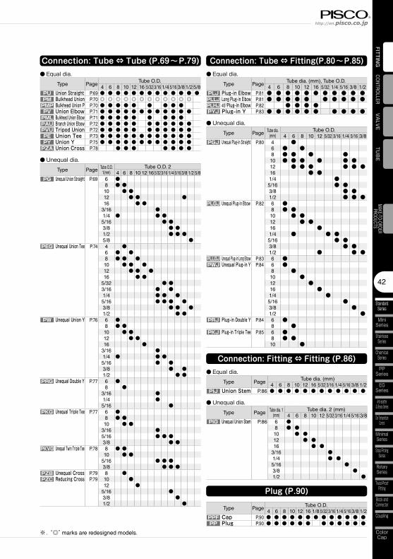
Connection: Tube ⇔ Tube (P.69〜P.79)
Type PageTube O.D.
4 6 8 10 12 16 5/32 3/16 1/4 5/16 3/81/2 5/8PU Union Straight P.69 ● ● ● ● ● ● ● ● ● ● ● ● ●PM Bulkhead Union P.70 ◎ ◎ ◎ ◎ ◎ ◎ ◎ ◎ ◎ ◎ ◎ ◎PMP Bulkhead Union P P.70 ● ● ● ● ● ● ● ● ●PV Union Elbow P.71 ● ● ● ● ● ● ● ● ● ● ● ●PML Bulkhead Union Elbow P.71 ● ● ● ● ● ● ● ● ●PAU Branch Union Elbow P.72 ● ● ● ● ● ● ● ● ● ● ●PVU Tripod Union P.72 ● ● ● ● ● ● ● ● ● ● ●PE Union Tee P.73 ● ● ● ● ● ● ● ● ● ● ● ●PY Union Y P.75 ● ● ● ● ● ● ● ● ● ● ● ●PZA Union Cross P.78 ● ● ● ● ● ● ●
Type Page Tube O.D. 1(mm)
Tube O.D. 24 6 8 10 12 16 5/32 3/16 1/4 5/16 3/8 1/2 5/8
PG Unequal Union Straight P.69 6 ●8 ● ●10 ● ●12 ● ● ●16 ● ●
3/16 ●1/4 ● ● ●5/16 ● ●3/8 ● ●1/2 ● ● ●5/8 ●
PEG Unequal Union Tee P.74 4 ●6 ● ●8 ● ● ●10 ● ● ●12 ● ● ●16 ● ●
5/32 ● ●3/16 ● ●1/4 ● ● ●5/16 ● ● ● ●3/8 ● ● ●1/2 ● ●
PW Unequal Union Y P.76 6 ●8 ● ●10 ● ●12 ● ●16 ●
3/16 ●1/4 ● ● ●5/16 ● ●3/8 ● ●1/2 ● ●
PRG Unequal Double Y P.77 6 ●8 ●
3/16 ●1/4 ●5/16 ●
PKG Unequal Triple Tee P.77 6 ●8 ● ●10 ● ●
3/16 ●5/16 ● ● ●3/8 ● ●
PKVG Unequal Twin Triple Tee P.78 8 ● ●10 ● ●
5/16 ● ● ●3/8 ● ● ●
PZB Unequal Cross P.79 8 ●PZC Reducing Cross P.79 10 ●
12 ●5/16 ●3/8 ●1/2 ●
Type PageTube dia. (mm), Tube O.D.
4 6 8 10 12 16 5/32 1/4 5/16 3/8 1/2PLJ Plug-in Elbow P.81 ● ● ● ● ● ● ● ● ● ● ●PLLJ Long Plug-in Elbow P.81 ● ● ● ● ● ● ● ● ● ●PLHJ 45°Plug-in Elbow P.82 ● ● ● ●PYJ Plug-in Y P.83 ● ● ● ● ● ● ● ● ● ●
Connection: Tube ⇔ Fitting(P.80〜P.85)
Type PageTube dia. (mm)
4 6 8 10 12 16 5/32 3/16 1/4 5/16 3/8 1/2PIJ Union Stem P.86 ● ● ● ● ● ● ● ● ● ● ● ●
Type Page Tube dia. 1 (mm)
Tube dia. 2 (mm)4 6 8 10 12 5/32 3/16 1/4 5/16 3/8
PIG Unequal Union Stem P.86 6 ●8 ● ●10 ● ●12 ● ●16 ● ●
3/16 ●1/4 ● ●5/16 ●3/8 ●1/2 ●
Type PageTube O.D.
4 6 8 10 12 16 1/8 5/32 3/16 1/4 5/16 3/8 1/2PPF Cap P.90 ● ● ● ● ● ● ● ● ● ● ● ● ●PP Plug P.90 ● ● ● ● ● ● ● ● ● ● ● ●
Connection: Fitting ⇔ Fitting (P.86)
Plug (P.90)
Type Page Tube dia. (mm)
Tube O.D.4 6 8 10 12 5/32 3/16 1/4 5/16 3/8
PGJ Unequal Plug-in Straight P.80 4 ●6 ● ●8 ● ● ● ●10 ● ● ● ● ● ●12 ● ● ● ● ● ●16 ● ●1/4 ●5/16 ● ●3/8 ● ●1/2 ● ● ●
PLGJ Unequal Plug-in Elbow P.82 6 ●8 ● ●10 ● ●12 ● ●16 ●1/4 ● ● ●5/16 ● ●3/8 ● ●1/2 ● ● ●
PLLGJ Unequal Plug-in Long Elbow P.83 6 ●PWJ Unequal Plug-in Y P.84 6 ●
8 ●10 ●12 ●16 ●1/4 ●5/16 ●3/8 ●1/2 ●
PRJ Plug-in Double Y P.84 6 ●8 ●
PKJ Plug-in Triple Tee P.85 6 ●8 ● ●10 ●
● Equal dia. ● Equal dia.
● Equal dia.
● Unequal dia.
● Unequal dia.
● Unequal dia.
※ . “◎” marks are redesigned models.
Fitting SeriesTube Fitting
StandardSeries
43
FITT
ING
Page for special specificationsOP.P.000 3D CAD data is available at PISCO website.CAD
3D CAD CAD data is available at PISCO website.
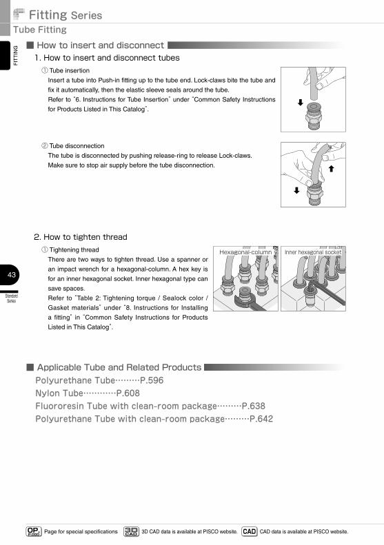
■ How to insert and disconnect1. How to insert and disconnect tubes① Tube insertion
Insert a tube into Push-in fitting up to the tube end. Lock-claws bite the tube and
fix it automatically, then the elastic sleeve seals around the tube.
Refer to “6. Instructions for Tube Insertion” under “Common Safety Instructions
for Products Listed in This Catalog”.
② Tube disconnection
The tube is disconnected by pushing release-ring to release Lock-claws.
Make sure to stop air supply before the tube disconnection.
2. How to tighten thread① Tightening thread
There are two ways to tighten thread. Use a spanner or
an impact wrench for a hexagonal-column. A hex key is
for an inner hexagonal socket. Inner hexagonal type can
save spaces.
Refer to “Table 2: Tightening torque / Sealock color /
Gasket materials” under “8. Instructions for Installing
a fitting” in “Common Safety Instructions for Products
Listed in This Catalog”.
Hexagonal-column Inner�hexagonal�socket
■ Applicable Tube and Related ProductsPolyurethane Tube………P.596Nylon Tube…………P.608Fluororesin Tube with clean-room package………P.638Polyurethane Tube with clean-room package………P.642
44
StandardSeries
MiniSeries
StainlessSeries
ChemicalSeries
PPSeries
EGSeries
Anti-spatter& Brass Series
Die TemperatureControl
MinimalSeries
Stop FittingSeries
RotarySeries
Twist-ProofFitting
Block andConnector
Coupling
ColorCap
FITTING
TUBE
VALVE
CONTROLLERMAKE-TO-ORDERPRODUCTS
http://en.pisco.co.jp
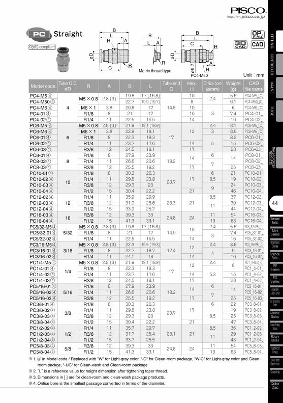
Unit:mm
Model codeTube O.D.
øD R A B LTube end
CHex.
HOrifice bore(ømm)
Weight(g)
CADfile name
PC4-M5④
4
M5×0.8 2.8 [3]19.8 17 [16.8]
14.9
102.4
5.6 PC4-M5_[C]PC4-M50④ 22.7 19.9 [19.7] 8 6.1 PC4-M50_[C]PC4-M6④ M6×1 3.8 20.8 17 10
36 PC4-M6_[C]
PC4-01④ R1/8 8 21 17 10 7.4 PC4-01_PC4-02④ R1/4 11 22.5 16.5 14 16 PC4-02_PC6-M5④
6
M5×0.8 2.8 [3] 21.9 19.1 [18.9]
1712
2.4 8.1 PC6-M5_[C]PC6-M6④ M6×1 3.8 22.9 19.1 3 8.5 PC6-M6_[C]PC6-01④ R1/8 8 22.3 18.3
58.2 PC6-01_
PC6-02④ R1/4 11 23.7 17.6 14 15 PC6-02_PC6-03④ R3/8 12 24.5 18.1 17 28 PC6-03_PC8-01④
8R1/8 8 27.9 23.9
18.214
614
PC8-01_PC8-02④ R1/4 11 26.6 20.6
7PC8-02_
PC8-03④ R3/8 12 25.5 19.2 17 25 PC8-03_PC10-01④
10
R1/8 8 30.3 26.3
20.717
6 21 PC10-01_PC10-02④ R1/4 11 29.8 23.8 8.5 19 PC10-02_PC10-03④ R3/8 12 29.3 23
924 PC10-03_
PC10-04④ R1/2 15 30.4 22.2 21 46 PC10-04_PC12-02④
12R1/4 11 35.9 29.9
23.3 218.5 37 PC12-02_
PC12-03④ R3/8 12 31.9 25.611
30 PC12-03_PC12-04④ R1/2 15 33.9 25.7 44 PC12-04_PC16-03④
16R3/8 12 39.3 33
24.8 2411 54 PC16-03_
PC16-04④ R1/2 15 41.3 33.1 13 63 PC16-04_PC5/32-M5④
5/32M5×0.8 2.8 [3] 19.8 17 [16.8]
14.910
2.4 5.6 PC5_32-M5[_C]PC5/32-01④ R1/8 8 21 17
37.4 PC5_32-01_
PC5/32-02④ R1/4 11 22.5 16.5 14 16 PC5_32-02_PC3/16-M5④
3/16M5×0.8 2.8 [3] 22.3 19.5 [19.3]
17.412
2.4 8.6 PC3_16-M5[_C]PC3/16-01④ R1/8 8 22.7 18.7
49 PC3_16-01_
PC3/16-02④ R1/4 11 24.1 18 14 16 PC3_16-02_PC1/4-M5④
1/4
M5×0.8 2.8 [3] 21.9 19.1 [18.9]
1712
2.48
PC1_4-M5[_C]PC1/4-01④ R1/8 8 22.3 18.3
5.3PC1_4-01_
PC1/4-02④ R1/4 11 23.7 17.6 14 15 PC1_4-02_PC1/4-03④ R3/8 12 24.5 18.1 17 28 PC1_4-03_PC5/16-01④
5/16R1/8 8 27.9 23.9
18.214
614
PC5_16-01_PC5/16-02④ R1/4 11 26.6 20.6
7PC5_16-02_
PC5/16-03④ R3/8 12 25.5 19.2 17 25 PC5_16-03_PC3/8-01④
3/8
R1/8 8 30.3 26.3
20.717
6 22 PC3_8-01_PC3/8-02④ R1/4 11 29.8 23.8
8.519 PC3_8-02_
PC3/8-03④ R3/8 12 29.3 23 25 PC3_8-03_PC3/8-04④ R1/2 15 30.4 22.2 21 47 PC3_8-04_PC1/2-02④
1/2R1/4 11 35.7 29.7
23.1 218.5 36 PC1_2-02_
PC1/2-03④ R3/8 12 31.7 25.411
29 PC1_2-03_PC1/2-04④ R1/2 15 33.7 25.5 43 PC1_2-04_PC5/8-03④
5/8R3/8 12 39.3 33
24.8 2411 54 PC5_8-03_
PC5/8-04④ R1/2 15 41.3 33.1 13 63 PC5_8-04_
※1. ④ in Model code / Replaced with "W" for Light-gray color, "-C" for Clean-room package, "W-C" for Light-gray color and Clean-
room packge, "-UC" for Clean-wash and Clean-room package
※2. “L” is a reference value for height dimension after tightening taper thread.
※3. Dimensions in [ ] are for clean-room and clean-wash package products.
※4. Orifice bore is the smallest passage converted in terms of the diameter.
PC
Metric thread typePC4-M50
øD
R
ø9.
7
BL B
A
L
C
CAL
BA
øD
R
R
H
H
OP.P.754
CADStraight
CAD3D
compliant
Fitting SeriesTube Fitting
StandardSeries
45
FITTING
Page for special specificationsOP.P.000 3D CAD data is available at PISCO website.CAD
3D CAD CAD data is available at PISCO website.
Metric thread type
øD
R
øZ
øP
B
L C
AH
ALB
R
Inner Hex. StraightPOC OP.P.754 CADCAD
3D
compliant
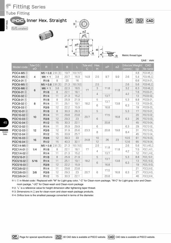
Unit:mm
Model codeTube O.D.
øD R A B LTube end
CHex.
HøP øZ Orifice bore
(ømm)Weight
(g)CAD
file name
POC4-M5④4
M5×0.8 2.8 [3] 19.7 16.9 [16.7]14.9 2.5 9.7 9.9 2.6
4.6 POC4-M5_[C]POC4-M6④ M6×1 3.8 20.7 16.9 5.4 POC4-M6_[C]POC4-01④ R1/8 8 20 16 6.6 POC4-01_POC6-M5④
6
M5×0.8 2.8 [3] 21.3 18.5 [18.3]
17
2.511.8
11.8
2.6 5.6 POC6-M5_[C]POC6-M6④ M6×1 3.8 22.3 18.5 3 3.2 6.3 POC6-M6_[C]POC6-01④ R1/8 8 22.1 18.1
4 4.27.6 POC6-01_
POC6-02④ R1/4 11 21.3 15.2 13.7 13 POC6-02_POC8-01④
8R1/8 8 25.9 21.9
18.25
13.713.8
5.3 8.8 POC8-01_POC8-02④ R1/4 11 25.1 19.1
6 6.313 POC8-02_
POC8-03④ R3/8 12 22.2 15.9 16.8 19 POC8-03_POC10-01④
10
R1/8 8 30.3 26.3
20.7
517.5
16.8
5.3 17 POC10-01_POC10-02④ R1/4 11 29.8 23.8
6 6.320 POC10-02_
POC10-03④ R3/8 12 29.3 23 26 POC10-03_POC10-04④ R1/2 15 30.3 22.1 20.8 45 POC10-04_POC12-02④
12R1/4 11 35.9 29.9
23.36
20.8 19.86.3 29 POC12-02_
POC12-03④ R3/8 12 31.9 25.68 8.4
31 POC12-03_POC12-04④ R1/2 15 33.9 25.7 45 POC12-04_POC16-03④
16R3/8 12 39.3 33
24.810
26 2310.5 61 POC16-03_
POC16-04④ R1/2 15 40.3 32.1 12 12.6 65 POC16-04_POC1/4-M5④
1/4M5×0.8 2.8 [3] 21.3 18.5 [18.3]
172.5
11.811.8
2.6 5.6 POC1_4-M5[_C]POC1/4-01④ R1/8 8 22.1 18.1
4 4.27.5 POC1_4-01_
POC1/4-02④ R1/4 11 21.3 15.2 13.7 12 POC1_4-02_POC5/16-01④
5/16R1/8 8 25.9 21.9
18.25
13.713.8
5.3 8.8 POC5_16-01_POC5/16-02④ R1/4 11 25.1 19.1
6 6.313 POC5_16-02_
POC5/16-03④ R3/8 12 22.2 15.9 16.8 19 POC5_16-03_POC3/8-02④
3/8R1/4 11 29.8 23.8
20.7 617.5
16.8 6.321 POC3_8-02_
POC3/8-03④ R3/8 12 29.3 23 27 POC3_8-03_POC3/8-04④ R1/2 15 30.3 22.1 20.8 46 POC3_8-04_
※1. ④ in Model code / Replaced with "W" for Light-gray color, "-C" for Clean-room package, "W-C" for Light-gray color and Clean-
room packge, "-UC" for Clean-wash and Clean-room package
※2. “L” is a reference value for height dimension after tightening taper thread.
※3. Dimensions in [ ] are for clean-room and clean-wash package products.
※4. Orifice bore is the smallest passage converted in terms of the diameter.
46
StandardSeries
MiniSeries
StainlessSeries
ChemicalSeries
PPSeries
EGSeries
Anti-spatter& Brass Series
Die TemperatureControl
MinimalSeries
Stop FittingSeries
RotarySeries
Twist-ProofFitting
Block andConnector
Coupling
ColorCap
FITTING
TUBE
VALVE
CONTROLLERMAKE-TO-ORDERPRODUCTS
http://en.pisco.co.jp
Page for special specificationsOP.P.000 3D CAD data is available at PISCO website.CAD
3D CAD CAD data is available at PISCO website.
øD
RcH
øP1
øP2
BE
T
CA
Female StraightPCF OP.P.754 CADCAD
3D
compliant
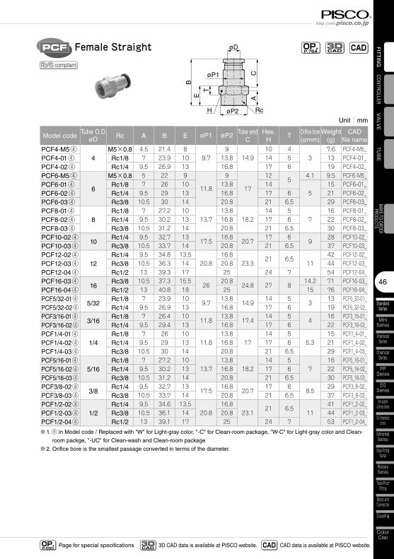
Unit:mm
Model codeTube O.D.
øD Rc A B E øP1 øP2 Tube endC
Hex.H
TOrifice bore(ømm)
Weight(g)
CADfile name
PCF4-M5④4
M5×0.8 4.5 21.4 89.7
914.9
10 43
7.6 PCF4-M5_PCF4-01④ Rc1/8 7 23.9 10 13.8 14 5 13 PCF4-01_PCF4-02④ Rc1/4 9.5 26.9 13 16.8 17 6 19 PCF4-02_PCF6-M5④
6
M5×0.8 5 22 9
11.8
9
17
125
4.1 9.5 PCF6-M5_PCF6-01④ Rc1/8 7 26 10 13.8 14
515 PCF6-01_
PCF6-02④ Rc1/4 9.5 29 13 16.8 17 6 21 PCF6-02_PCF6-03④ Rc3/8 10.5 30 14 20.8 21 6.5 29 PCF6-03_PCF8-01④
8Rc1/8 7 27.2 10
13.713.8
18.214 5
716 PCF8-01_
PCF8-02④ Rc1/4 9.5 30.2 13 16.8 17 6 22 PCF8-02_PCF8-03④ Rc3/8 10.5 31.2 14 20.8 21 6.5 30 PCF8-03_PCF10-02④
10Rc1/4 9.5 32.7 13
17.516.8
20.717 6
928 PCF10-02_
PCF10-03④ Rc3/8 10.5 33.7 14 20.8 21 6.5 37 PCF10-03_PCF12-02④
12Rc1/4 9.5 34.8 13.5
20.816.8
23.321 6.5
1142 PCF12-02_
PCF12-03④ Rc3/8 10.5 36.3 14 20.8 44 PCF12-03_PCF12-04④ Rc1/2 13 39.3 17 25 24 7 54 PCF12-04_PCF16-03④
16Rc3/8 10.5 37.3 15.5
2620.8
24.8 27 814.2 71 PCF16-03_
PCF16-04④ Rc1/2 13 40.8 18 25 15 76 PCF16-04_PCF5/32-01④
5/32Rc1/8 7 23.9 10
9.713.8
14.914 5
313 PCF5_32-01_
PCF5/32-02④ Rc1/4 9.5 26.9 13 16.8 17 6 19 PCF5_32-02_PCF3/16-01④
3/16Rc1/8 7 26.4 10
11.813.8
17.414 5
416 PCF3_16-01_
PCF3/16-02④ Rc1/4 9.5 29.4 13 16.8 17 6 22 PCF3_16-02_PCF1/4-01④
1/4Rc1/8 7 26 10
11.813.8
1714 5
5.315 PCF1_4-01_
PCF1/4-02④ Rc1/4 9.5 29 13 16.8 17 6 21 PCF1_4-02_PCF1/4-03④ Rc3/8 10.5 30 14 20.8 21 6.5 29 PCF1_4-03_PCF5/16-01④
5/16Rc1/8 7 27.2 10
13.713.8
18.214 5
716 PCF5_16-01_
PCF5/16-02④ Rc1/4 9.5 30.2 13 16.8 17 6 22 PCF5_16-02_PCF5/16-03④ Rc3/8 10.5 31.2 14 20.8 21 6.5 30 PCF5_16-03_PCF3/8-02④
3/8Rc1/4 9.5 32.7 13
17.516.8
20.717 6
8.529 PCF3_8-02_
PCF3/8-03④ Rc3/8 10.5 33.7 14 20.8 21 6.5 37 PCF3_8-03_PCF1/2-02④
1/2Rc1/4 9.5 34.6 13.5
20.816.8
23.121 6.5
1141 PCF1_2-02_
PCF1/2-03④ Rc3/8 10.5 36.1 14 20.8 44 PCF1_2-03_PCF1/2-04④ Rc1/2 13 39.1 17 25 24 7 53 PCF1_2-04_
※1. ④ in Model code / Replaced with "W" for Light-gray color, "-C" for Clean-room package, "W-C" for Light-gray color and Clean-
room packge, "-UC" for Clean-wash and Clean-room package
※2. Orifice bore is the smallest passage converted in terms of the diameter.
Fitting SeriesTube Fitting
StandardSeries
47
FITTING
Page for special specificationsOP.P.000 3D CAD data is available at PISCO website.CAD
3D CAD CAD data is available at PISCO website.
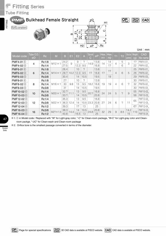
Unit:mm
Model codeTube O.D.
øD Rc M B E1 E2 ATube end
CøP Hex.
H1Hex.H2
T1 T2Orifice bore(ømm)
Weight(g)
CADfile name
PMF4-01④4
Rc1/8M12×1
24.29
9 714.9
13.814
144
53
17 PMF4-01_PMF4-02④ Rc1/4 27.5 12.3 9.5 16.8 17 6 22 PMF4-02_PMF6-01④
6Rc1/8
M14×126.4
10.210 7
1713.8
1717
4 6 525 PMF6-01_
PMF6-02④ Rc1/4 28.7 12.3 9.5 16.8 26 PMF6-02_PMF6-03④ Rc3/8 30.4 14 10.5 19.5 19 29 PMF6-03_PMF8-01④
8Rc1/8
M16×127
9.810 7
18.213.8
19 19 4 6 730 PMF8-01_
PMF8-02④ Rc1/4 30 13 9.5 16.8 32 PMF8-02_PMF8-03④ Rc3/8 31 14 10.5 19.5 30 PMF8-03_PMF10-02④
10Rc1/4
M20×132.7
11.113 9.5
20.716.8
24 24 5 7 955 PMF10-02_
PMF10-03④ Rc3/8 33.7 14 10.5 20.8 56 PMF10-03_PMF12-02④
12Rc1/4
M22×135.3
12.413 9.5
23.316.8
27 24 6 7 1165
PMF12-02_PMF12-03④ Rc3/8 36.3 14 10.5 20.8 PMF12-03_PMF12-04④ Rc1/2 39.3 17 13 25 67 PMF12-04_PMF16-03④
16Rc3/8
M27×1.538.3
14.414 10.5
24.820.8
32 29 9 8.514.2
110PMF16-03_
PMF16-04④ Rc1/2 40.8 16.5 13 25 15 PMF16-04_
※1. ④ in Model code / Replaced with "W" for Light-gray color, "-C" for Clean-room package, "W-C" for Light-gray color and Clean-
room packge, "-UC" for Clean-wash and Clean-room package
※2. Orifice bore is the smallest passage converted in terms of the diameter.
øD
Rc
M
øP
BE
2E
1 T1
T2
CA
H2
H1Bulkhead Female StraightPMF OP.
P.754 CADCAD3D
compliant
48
StandardSeries
MiniSeries
StainlessSeries
ChemicalSeries
PPSeries
EGSeries
Anti-spatter& Brass Series
Die TemperatureControl
MinimalSeries
Stop FittingSeries
RotarySeries
Twist-ProofFitting
Block andConnector
Coupling
ColorCap
FITTING
TUBE
VALVE
CONTROLLERMAKE-TO-ORDERPRODUCTS
http://en.pisco.co.jp
Page for special specificationsOP.P.000 3D CAD data is available at PISCO website.CAD
3D CAD CAD data is available at PISCO website.
Unit:mm
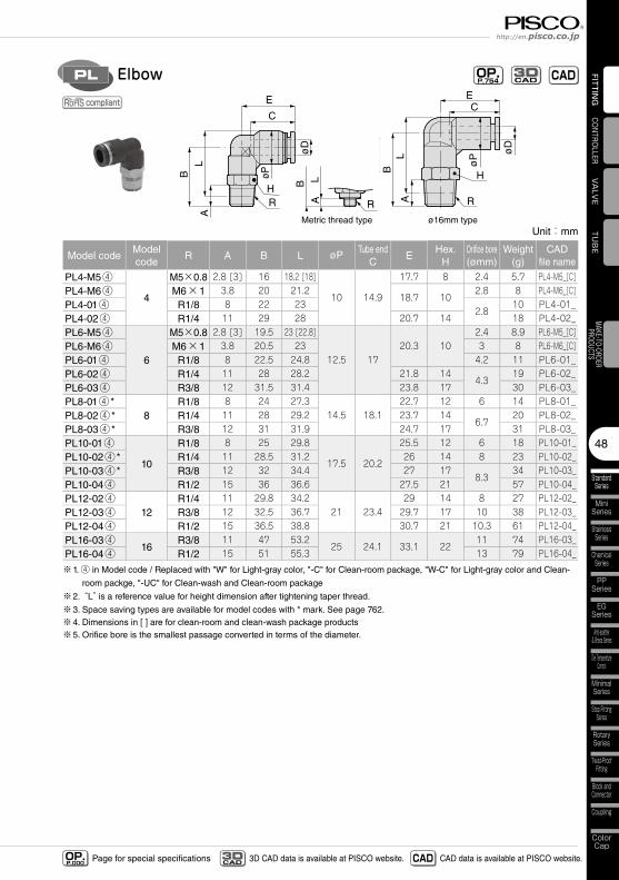
Model codeModel code
R A B L øP Tube endC
EHex.
HOrifice bore(ømm)
Weight(g)
CADfile name
PL4-M5④
4
M5×0.8 2.8 [3] 16 18.2 [18]
10 14.9
17.7 8 2.4 5.7 PL4-M5_[C]PL4-M6④ M6×1 3.8 20 21.2
18.7 102.8 8 PL4-M6_[C]
PL4-01④ R1/8 8 22 232.8
10 PL4-01_PL4-02④ R1/4 11 29 28 20.7 14 18 PL4-02_PL6-M5④
6
M5×0.8 2.8 [3] 19.5 23 [22.8]
12.5 1720.3 10
2.4 8.9 PL6-M5_[C]PL6-M6④ M6×1 3.8 20.5 23 3 8 PL6-M6_[C]PL6-01④ R1/8 8 22.5 24.8 4.2 11 PL6-01_PL6-02④ R1/4 11 28 28.2 21.8 14
4.319 PL6-02_
PL6-03④ R3/8 12 31.5 31.4 23.8 17 30 PL6-03_PL8-01④ *
8R1/8 8 24 27.3
14.5 18.122.7 12 6 14 PL8-01_
PL8-02④ * R1/4 11 28 29.2 23.7 146.7
20 PL8-02_PL8-03④ * R3/8 12 31 31.9 24.7 17 31 PL8-03_PL10-01④
10
R1/8 8 25 29.8
17.5 20.2
25.5 12 6 18 PL10-01_PL10-02④ * R1/4 11 28.5 31.2 26 14 8 23 PL10-02_PL10-03④ * R3/8 12 32 34.4 27 17
8.334 PL10-03_
PL10-04④ R1/2 15 36 36.6 27.5 21 57 PL10-04_PL12-02④
12R1/4 11 29.8 34.2
21 23.429 14 8 27 PL12-02_
PL12-03④ R3/8 12 32.5 36.7 29.7 17 10 38 PL12-03_PL12-04④ R1/2 15 36.5 38.8 30.7 21 10.3 61 PL12-04_PL16-03④
16R3/8 11 47 53.2
25 24.1 33.1 2211 74 PL16-03_
PL16-04④ R1/2 15 51 55.3 13 79 PL16-04_
※1. ④ in Model code / Replaced with "W" for Light-gray color, "-C" for Clean-room package, "W-C" for Light-gray color and Clean-
room packge, "-UC" for Clean-wash and Clean-room package
※2. “L” is a reference value for height dimension after tightening taper thread.
※3. Space saving types are available for model codes with * mark. See page 762.※4. Dimensions in [ ] are for clean-room and clean-wash package products※5. Orifice bore is the smallest passage converted in terms of the diameter.
øD
H
øP
LB
C
E
AR
Metric thread type
RALB
ø16mm type
R
øD
øP
CE
LB
A
H
ElbowPL OP.P.754 CADCAD
3D
compliant
Fitting SeriesTube Fitting
StandardSeries
49
FITTING
Page for special specificationsOP.P.000 3D CAD data is available at PISCO website.CAD
3D CAD CAD data is available at PISCO website.
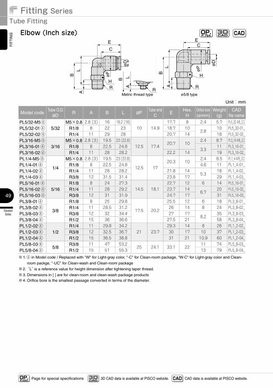
Unit:mm
Model codeTube O.D.øD
R A B L øPTube end
CE
Hex.H
Orifice bore(ømm)
Weight(g)
CADfile name
PL5/32-M5④5/32
M5×0.8 2.8 [3] 16 18.2 [18]10 14.9
17.7 8 2.4 5.7 PL5_32-M5_[C]PL5/32-01④ R1/8 8 22 23 18.7 10
2.810 PL5_32-01_
PL5/32-02④ R1/4 11 29 28 20.7 14 18 PL5_32-02_PL3/16-M5④
3/16M5×0.8 2.8 [3] 19.5 23 [22.8]
12.5 17.420.7 10
2.4 8.7 PL3_16-M5_[C]PL3/16-01④ R1/8 8 22.5 24.8
3.311 PL3_16-01_
PL3/16-02④ R1/4 11 28 28.2 22.2 14 19 PL3_16-02_PL1/4-M5④
1/4
M5×0.8 2.8 [3] 19.5 23 [22.8]
12.5 1720.3 10
2.4 8.5 PL1_4-M5_[C]PL1/4-01④ R1/8 8 22.5 24.8 4.6 11 PL1_4-01_PL1/4-02④ R1/4 11 28 28.2 21.8 14
5.318 PL1_4-02_
PL1/4-03④ R3/8 12 31.5 31.4 23.8 17 29 PL1_4-03_PL5/16-01④
5/16R1/8 8 24 27.3
14.5 18.122.7 12 6 14 PL5_16-01_
PL5/16-02④ R1/4 11 28 29.2 23.7 146.7
20 PL5_16-02_PL5/16-03④ R3/8 12 31 31.9 24.7 17 31 PL5_16-03_PL3/8-01④
3/8
R1/8 8 25 29.8
17.5 20.2
25.5 12 6 18 PL3_8-01_PL3/8-02④ R1/4 11 28.5 31.2 26 14 8 24 PL3_8-02_PL3/8-03④ R3/8 12 32 34.4 27 17
8.235 PL3_8-03_
PL3/8-04④ R1/2 15 36 36.6 27.5 21 58 PL3_8-04_PL1/2-02④
1/2R1/4 11 29.8 34.2
21 23.729.3 14 8 26 PL1_2-02_
PL1/2-03④ R3/8 12 32.5 36.7 30 17 10 37 PL1_2-03_PL1/2-04④ R1/2 15 36.5 38.8 31 21 10.9 60 PL1_2-04_PL5/8-03④
5/8R3/8 11 47 53.2
25 24.1 33.1 2211 74 PL5_8-03_
PL5/8-04④ R1/2 15 51 55.3 13 79 PL5_8-04_
※1. ④ in Model code / Replaced with "W" for Light-gray color, "-C" for Clean-room package, "W-C" for Light-gray color and Clean-
room packge, "-UC" for Clean-wash and Clean-room package
※2. “L” is a reference value for height dimension after tightening taper thread.
※3. Dimensions in [ ] are for clean-room and clean-wash package products※4. Orifice bore is the smallest passage converted in terms of the diameter.
øD
H
øP
LB
C
E
A
R
Metric thread typeR
ALB
ø5/8 type
R
øD
øP
CE
LB
A
H
Elbow (Inch size) OP.P.754 CADCAD
3D
50
StandardSeries
MiniSeries
StainlessSeries
ChemicalSeries
PPSeries
EGSeries
Anti-spatter& Brass Series
Die TemperatureControl
MinimalSeries
Stop FittingSeries
RotarySeries
Twist-ProofFitting
Block andConnector
Coupling
ColorCap
FITTING
TUBE
VALVE
CONTROLLERMAKE-TO-ORDERPRODUCTS
http://en.pisco.co.jp
Page for special specificationsOP.P.000 3D CAD data is available at PISCO website.CAD
3D CAD CAD data is available at PISCO website.
Metric thread type ø16mm type
øD
RH
øP
LB
CE
A
ALB
R
H
R
øD
øP
CE
LB
A
Long ElbowPLL OP.P.754 CADCAD
3D
compliant
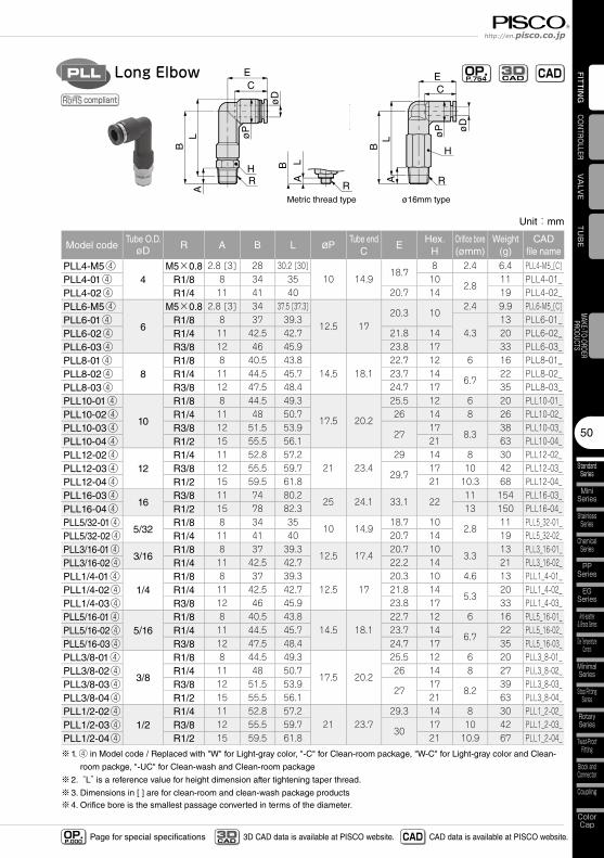
Unit:mm
Model codeTube O.D.
øD R A B L øPTube end
CE
Hex.H
Orifice bore(ømm)
Weight(g)
CADfile name
PLL4-M5④4
M5×0.8 2.8 [3] 28 30.2 [30]10 14.9
18.78 2.4 6.4 PLL4-M5_[C]
PLL4-01④ R1/8 8 34 35 102.8
11 PLL4-01_PLL4-02④ R1/4 11 41 40 20.7 14 19 PLL4-02_PLL6-M5④
6
M5×0.8 2.8 [3] 34 37.5 [37.3]
12.5 1720.3 10
2.4 9.9 PLL6-M5_[C]PLL6-01④ R1/8 8 37 39.3
4.313 PLL6-01_
PLL6-02④ R1/4 11 42.5 42.7 21.8 14 20 PLL6-02_PLL6-03④ R3/8 12 46 45.9 23.8 17 33 PLL6-03_PLL8-01④
8R1/8 8 40.5 43.8
14.5 18.122.7 12 6 16 PLL8-01_
PLL8-02④ R1/4 11 44.5 45.7 23.7 146.7
22 PLL8-02_PLL8-03④ R3/8 12 47.5 48.4 24.7 17 35 PLL8-03_PLL10-01④
10
R1/8 8 44.5 49.3
17.5 20.2
25.5 12 6 20 PLL10-01_PLL10-02④ R1/4 11 48 50.7 26 14 8 26 PLL10-02_PLL10-03④ R3/8 12 51.5 53.9
2717
8.338 PLL10-03_
PLL10-04④ R1/2 15 55.5 56.1 21 63 PLL10-04_PLL12-02④
12R1/4 11 52.8 57.2
21 23.429 14 8 30 PLL12-02_
PLL12-03④ R3/8 12 55.5 59.729.7
17 10 42 PLL12-03_PLL12-04④ R1/2 15 59.5 61.8 21 10.3 68 PLL12-04_PLL16-03④
16R3/8 11 74 80.2
25 24.1 33.1 2211 154 PLL16-03_
PLL16-04④ R1/2 15 78 82.3 13 150 PLL16-04_PLL5/32-01④
5/32R1/8 8 34 35
10 14.918.7 10
2.811 PLL5_32-01_
PLL5/32-02④ R1/4 11 41 40 20.7 14 19 PLL5_32-02_PLL3/16-01④
3/16R1/8 8 37 39.3
12.5 17.420.7 10
3.313 PLL3_16-01_
PLL3/16-02④ R1/4 11 42.5 42.7 22.2 14 21 PLL3_16-02_PLL1/4-01④
1/4R1/8 8 37 39.3
12.5 1720.3 10 4.6 13 PLL1_4-01_
PLL1/4-02④ R1/4 11 42.5 42.7 21.8 145.3
20 PLL1_4-02_PLL1/4-03④ R3/8 12 46 45.9 23.8 17 33 PLL1_4-03_PLL5/16-01④
5/16R1/8 8 40.5 43.8
14.5 18.122.7 12 6 16 PLL5_16-01_
PLL5/16-02④ R1/4 11 44.5 45.7 23.7 146.7
22 PLL5_16-02_PLL5/16-03④ R3/8 12 47.5 48.4 24.7 17 35 PLL5_16-03_PLL3/8-01④
3/8
R1/8 8 44.5 49.3
17.5 20.2
25.5 12 6 20 PLL3_8-01_PLL3/8-02④ R1/4 11 48 50.7 26 14 8 27 PLL3_8-02_PLL3/8-03④ R3/8 12 51.5 53.9
2717
8.239 PLL3_8-03_
PLL3/8-04④ R1/2 15 55.5 56.1 21 63 PLL3_8-04_PLL1/2-02④
1/2R1/4 11 52.8 57.2
21 23.729.3 14 8 30 PLL1_2-02_
PLL1/2-03④ R3/8 12 55.5 59.730
17 10 42 PLL1_2-03_PLL1/2-04④ R1/2 15 59.5 61.8 21 10.9 67 PLL1_2-04_
※1. ④ in Model code / Replaced with "W" for Light-gray color, "-C" for Clean-room package, "W-C" for Light-gray color and Clean-
room packge, "-UC" for Clean-wash and Clean-room package
※2. “L” is a reference value for height dimension after tightening taper thread.
※3. Dimensions in [ ] are for clean-room and clean-wash package products※4. Orifice bore is the smallest passage converted in terms of the diameter.
Fitting SeriesTube Fitting
StandardSeries
51
FITTING
Page for special specificationsOP.P.000 3D CAD data is available at PISCO website.CAD
3D CAD CAD data is available at PISCO website.
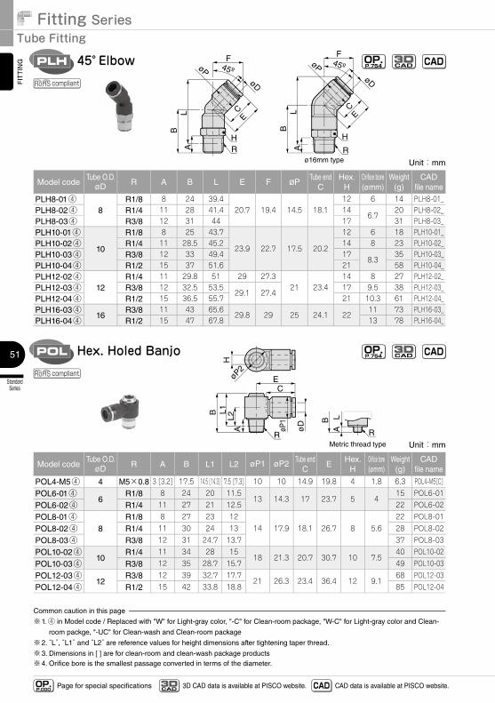
Unit:mm
Model codeTube O.D.
øD R A B L E F øPTube end
CHex.
HOrifice bore(ømm)
Weight(g)
CADfile name
PLH8-01④8
R1/8 8 24 39.420.7 19.4 14.5 18.1
12 6 14 PLH8-01_PLH8-02④ R1/4 11 28 41.4 14
6.7 20 PLH8-02_
PLH8-03④ R3/8 12 31 44 17 31 PLH8-03_PLH10-01④
10
R1/8 8 25 43.7
23.9 22.7 17.5 20.2
12 6 18 PLH10-01_PLH10-02④ R1/4 11 28.5 45.2 14 8 23 PLH10-02_PLH10-03④ R3/8 12 33 49.4 17
8.3 35 PLH10-03_
PLH10-04④ R1/2 15 37 51.6 21 58 PLH10-04_PLH12-02④
12R1/4 11 29.8 51 29 27.3
21 23.414 8 27 PLH12-02_
PLH12-03④ R3/8 12 32.5 53.529.1 27.4
17 9.5 38 PLH12-03_PLH12-04④ R1/2 15 36.5 55.7 21 10.3 61 PLH12-04_PLH16-03④
16R3/8 11 43 65.6
29.8 29 25 24.1 2211 73 PLH16-03_
PLH16-04④ R1/2 15 47 67.8 13 78 PLH16-04_
RA A R
45º45º
F F
B B
L L
H H
EC
EC
øDøD
øPøP
ø16mm type
45° ElbowPLH
Unit:mm
Model codeTube O.D.
øD R A B L1 L2 øP1 øP2 Tube endC
EHex.
HOrifice bore(ømm)
Weight(g)
CADfile name
POL4-M5④ 4 M5×0.8 3 [3.2] 17.5 14.5 [14.3] 7.5 [7.3] 10 10 14.9 19.8 4 1.8 6.3 POL4-M5[C]
POL6-01④6
R1/8 8 24 20 11.513 14.3 17 23.7 5 4
15 POL6-01
POL6-02④ R1/4 11 27 21 12.5 22 POL6-02
POL8-01④8
R1/8 8 27 23 1214 17.9 18.1 26.7 8 5.6
22 POL8-01
POL8-02④ R1/4 11 30 24 13 28 POL8-02
POL8-03④ R3/8 12 31 24.7 13.7 37 POL8-03
POL10-02④10
R1/4 11 34 28 1518 21.3 20.7 30.7 10 7.5
40 POL10-02
POL10-03④ R3/8 12 35 28.7 15.7 49 POL10-03
POL12-03④12
R3/8 12 39 32.7 17.721 26.3 23.4 36.4 12 9.1
68 POL12-03
POL12-04④ R1/2 15 42 33.8 18.8 85 POL12-04
Common caution in this page
※1. ④ in Model code / Replaced with "W" for Light-gray color, "-C" for Clean-room package, "W-C" for Light-gray color and Clean-
room packge, "-UC" for Clean-wash and Clean-room package
※2. “L”, “L1” and “L2” are reference values for height dimensions after tightening taper thread.
※3. Dimensions in [ ] are for clean-room and clean-wash package products※4. Orifice bore is the smallest passage converted in terms of the diameter.
øD
øP1
CE
B L1L2
A
R
H
RMetric thread type
BA
L
øP2
Hex. Holed BanjoPOL
OP.P.754 CADCAD
3D
OP.P.754 CADCAD
3D
compliant
compliant
52
StandardSeries
MiniSeries
StainlessSeries
ChemicalSeries
PPSeries
EGSeries
Anti-spatter& Brass Series
Die TemperatureControl
MinimalSeries
Stop FittingSeries
RotarySeries
Twist-ProofFitting
Block andConnector
Coupling
ColorCap
FITTING
TUBE
VALVE
CONTROLLERMAKE-TO-ORDERPRODUCTS
http://en.pisco.co.jp
Page for special specificationsOP.P.000 3D CAD data is available at PISCO website.CAD
3D CAD CAD data is available at PISCO website.
Rc
CE
LB
A H
øP
øD
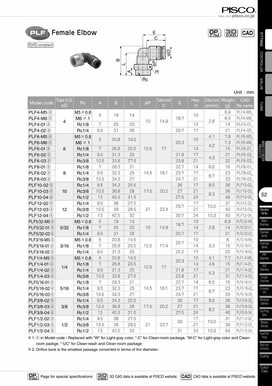
Female ElbowPLF OP.P.754 CADCAD
3D
compliant
Unit:mm
Model codeTube O.D.
øD Rc A B L øPTube end
CE
Hex.H
Orifice bore(ømm)
Weight(g)
CADfile name
PLF4-M5④
4
M5×0.85 19 14
10 14.918.7
102.8
6.9 PLF4-M5_PLF4-M6④ M6×1 6.4 PLF4-M6_PLF4-01④ Rc1/8 7 25 20 14 14 PLF4-01_PLF4-02④ Rc1/4 9.5 31 26 20.7 17 21 PLF4-02_PLF6-M5④
6
M5×0.85 20.8 14.5
12.5 1720.3
104.1 7.8 PLF6-M5_
PLF6-M6④ M6×14.2
7.3 PLF6-M6_PLF6-01④ Rc1/8 7 26.8 20.5 14 15 PLF6-01_PLF6-02④ Rc1/4 9.5 31.3 25 21.8 17
4.321 PLF6-02_
PLF6-03④ Rc3/8 10.5 33.8 27.5 23.8 21 32 PLF6-03_PLF8-01④
8Rc1/8 7 28.3 21
14.5 18.122.7 14 6.0 16 PLF8-01_
PLF8-02④ Rc1/4 9.5 32.3 25 23.7 176.7
23 PLF8-02_PLF8-03④ Rc3/8 10.5 34.3 27 24.7 21 33 PLF8-03_PLF10-02④
10Rc1/4 9.5 34.3 25.5
17.5 20.226 17 8.0 26 PLF10-02_
PLF10-03④ Rc3/8 10.5 36.8 28 27 218.3
36 PLF10-03_PLF10-04④ Rc1/2 13 40.3 31.5 27.5 24 46 PLF10-04_PLF12-02④
12Rc1/4 9.5 38 27.5
21 23.429.7
1710.0
31 PLF12-02_PLF12-03④ Rc3/8 10.5 39 28.5 21 40 PLF12-03_PLF12-04④ Rc1/2 13 42.5 32 30.7 24 10.3 50 PLF12-04_PLF5/32-M5④
5/32M5×0.8 5 19 14
10 14.918.7
102.8
6.9 PLF5/32-M5_PLF5/32-01④ Rc1/8 7 25 20 14 14 PLF5/32-01_PLF5/32-02④ Rc1/4 9.5 31 26 20.7 17 21 PLF5/32-02_PLF3/16-M5④
3/16M5×0.8 5 20.8 14.5
12.5 17.420.7
103.3
8 PLF3/16-M5_PLF3/16-01④ Rc1/8 7 26.8 20.5 14 15 PLF3/16-01_PLF3/16-02④ Rc1/4 9.5 31.3 25 22.2 17 22 PLF3/16-02_PLF1/4-M5④
1/4
M5×0.8 5 20.8 14.5
12.5 1720.3
10 4.1 7.7 PLF1/4-M5_PLF1/4-01④ Rc1/8 7 26.8 20.5 14 4.6 15 PLF1/4-01_PLF1/4-02④ Rc1/4 9.5 31.3 25 21.8 17
5.321 PLF1/4-02_
PLF1/4-03④ Rc3/8 10.5 33.8 27.5 23.8 21 31 PLF1/4-03_PLF5/16-01④
5/16Rc1/8 7 28.3 21
14.5 18.122.7 14 6.0 16 PLF5/16-01_
PLF5/16-02④ Rc1/4 9.5 32.3 25 23.7 176.7
23 PLF5/16-02_PLF5/16-03④ Rc3/8 10.5 34.3 27 24.7 21 33 PLF5/16-03_PLF3/8-02④
3/8Rc1/4 9.5 34.3 25.5
17.5 20.226 17 8.0 26 PLF3/8-02_
PLF3/8-03④ Rc3/8 10.5 36.8 28 27 218.2
36 PLF3/8-03_PLF3/8-04④ Rc1/2 13 40.3 31.5 27.5 24 46 PLF3/8-04_PLF1/2-02④
1/2Rc1/4 9.5 38 27.5
21 23.730
1710.0
31 PLF1/2-02_PLF1/2-03④ Rc3/8 10.5 39 28.5 21 39 PLF1/2-03_PLF1/2-04④ Rc1/2 13 42.5 32 31 24 10.9 54 PLF1/2-04_
※1. ④ in Model code / Replaced with "W" for Light-gray color, "-C" for Clean-room package, "W-C" for Light-gray color and Clean-
room packge, "-UC" for Clean-wash and Clean-room package
※2. Orifice bore is the smallest passage converted in terms of the diameter.
Fitting SeriesTube Fitting
StandardSeries
53
FITTING
Page for special specificationsOP.P.000 3D CAD data is available at PISCO website.CAD
3D CAD CAD data is available at PISCO website.
R R
LB
Metric thread type
BA
L
J
E
A
H
2-C
2-ø
D2-
øP
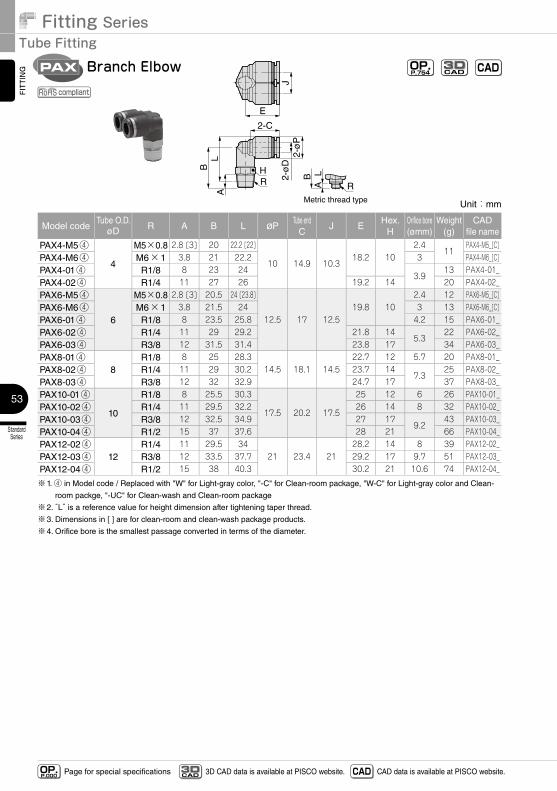
Branch ElbowPAX OP.P.754 CADCAD
3D
compliant
Unit:mm
Model codeTube O.D.
øD R A B L øPTube end
CJ E
Hex.H
Orifice bore(ømm)
Weight(g)
CADfile name
PAX4-M5④
4
M5×0.8 2.8 [3] 20 22.2 [22]
10 14.9 10.318.2 10
2.411
PAX4-M5_[C]PAX4-M6④ M6×1 3.8 21 22.2 3 PAX4-M6_[C]PAX4-01④ R1/8 8 23 24
3.913 PAX4-01_
PAX4-02④ R1/4 11 27 26 19.2 14 20 PAX4-02_PAX6-M5④
6
M5×0.8 2.8 [3] 20.5 24 [23.8]
12.5 17 12.519.8 10
2.4 12 PAX6-M5_[C]PAX6-M6④ M6×1 3.8 21.5 24 3 13 PAX6-M6_[C]PAX6-01④ R1/8 8 23.5 25.8 4.2 15 PAX6-01_PAX6-02④ R1/4 11 29 29.2 21.8 14
5.322 PAX6-02_
PAX6-03④ R3/8 12 31.5 31.4 23.8 17 34 PAX6-03_PAX8-01④
8R1/8 8 25 28.3
14.5 18.1 14.522.7 12 5.7 20 PAX8-01_
PAX8-02④ R1/4 11 29 30.2 23.7 147.3
25 PAX8-02_PAX8-03④ R3/8 12 32 32.9 24.7 17 37 PAX8-03_PAX10-01④
10
R1/8 8 25.5 30.3
17.5 20.2 17.5
25 12 6 26 PAX10-01_PAX10-02④ R1/4 11 29.5 32.2 26 14 8 32 PAX10-02_PAX10-03④ R3/8 12 32.5 34.9 27 17
9.243 PAX10-03_
PAX10-04④ R1/2 15 37 37.6 28 21 66 PAX10-04_PAX12-02④
12R1/4 11 29.5 34
21 23.4 2128.2 14 8 39 PAX12-02_
PAX12-03④ R3/8 12 33.5 37.7 29.2 17 9.7 51 PAX12-03_PAX12-04④ R1/2 15 38 40.3 30.2 21 10.6 74 PAX12-04_
※1. ④ in Model code / Replaced with "W" for Light-gray color, "-C" for Clean-room package, "W-C" for Light-gray color and Clean-
room packge, "-UC" for Clean-wash and Clean-room package
※2. “L” is a reference value for height dimension after tightening taper thread.
※3. Dimensions in [ ] are for clean-room and clean-wash package products.
※4. Orifice bore is the smallest passage converted in terms of the diameter.
54
StandardSeries
MiniSeries
StainlessSeries
ChemicalSeries
PPSeries
EGSeries
Anti-spatter& Brass Series
Die TemperatureControl
MinimalSeries
Stop FittingSeries
RotarySeries
Twist-ProofFitting
Block andConnector
Coupling
ColorCap
FITTING
TUBE
VALVE
CONTROLLERMAKE-TO-ORDERPRODUCTS
http://en.pisco.co.jp
Page for special specificationsOP.P.000 3D CAD data is available at PISCO website.CAD
3D CAD CAD data is available at PISCO website.
Unit:mm
Model codeTube O.D.
øD R A B L øPTube end
CE
Hex.H
Orifice bore(ømm)
Weight(g)
CADfile name
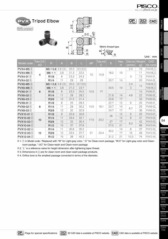
PVX4-M5④
4
M5×0.8 2.8 [3] 20.3 22.5 [22.3]
10 14.918.2 10
2.4 10 PVX4-M5_[C]PVX4-M6④ M6×1 3.8 21.3 22.5
311 PVX4-M6_[C]
PVX4-01④ R1/8 8 23.3 24.3 13 PVX4-01_PVX4-02④ R1/4 11 29 28 20.7 14 20 PVX4-02_PVX6-M5④
6
M5×0.8 2.8 [3] 20.3 23.7 [23.5]
12.5 1720.5 10
2.412
PVX6-M5_[C]PVX6-M6④ M6×1 3.8 21.3 23.7 3 PVX6-M6_[C]PVX6-01④ R1/8 8 23.3 25.5
4.615 PVX6-01_
PVX6-02④ R1/4 11 28 28.2 21.8 14 22 PVX6-02_PVX6-03④ R3/8 12 31.5 31.4 23.8 17 33 PVX6-03_PVX8-01④
8R1/8 8 25 28.3
14.5 18.122.7 12 6 20 PVX8-01_
PVX8-02④ R1/4 11 29 30.2 23.7 146.7
25 PVX8-02_PVX8-03④ R3/8 12 32 32.9 24.7 17 36 PVX8-03_PVX10-01④
10
R1/8 8 25.9 30.6
17.5 20.226
12 6 25 PVX10-01_PVX10-02④ R1/4 11 29.4 32.1 14 8 31 PVX10-02_PVX10-03④ R3/8 12 33 35.4 27 17
8.342 PVX10-03_
PVX10-04④ R1/2 15 37 37.6 27.5 21 66 PVX10-04_PVX12-02④
12R1/4 11 30.8 35.2
21 23.430.2
14 8 37 PVX12-02_PVX12-03④ R3/8 12 33.5 37.7 17 10 49 PVX12-03_PVX12-04④ R1/2 15 38 40.3 31.2 21 10.3 74 PVX12-04_
※1. ④ in Model code / Replaced with "W" for Light-gray color, "-C" for Clean-room package, "W-C" for Light-gray color and Clean-
room packge, "-UC" for Clean-wash and Clean-room package
※2. “L” is a reference value for height dimension after tightening taper thread.
※3. Dimensions in [ ] are for clean-room and clean-wash package products.
※4. Orifice bore is the smallest passage converted in terms of the diameter.
R R
Metric thread type
BA
L
BL
A
H
2-ø
D2-C
2-øP2-E
Tripod ElbowPVX OP.P.754 CADCAD
3D
compliant
Fitting SeriesTube Fitting
StandardSeries
55
FITTING
Page for special specificationsOP.P.000 3D CAD data is available at PISCO website.CAD
3D CAD CAD data is available at PISCO website.
øD
øP
1
CE
B L1L2
A R
H
RMetric thread type
BA
L
øP2
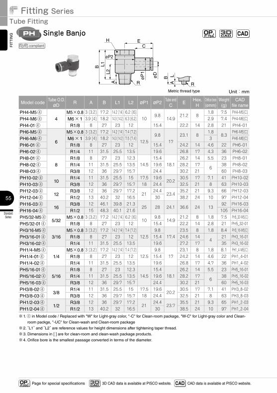
Single BanjoPH OP.P.754 CADCAD
3D
compliant
Unit:mm
Model codeTube O.D.øD
R A B L1 L2 øP1 øP2Tube end
CE
Hex.H
Orifice bore(ømm)
Weight(g)
CADfile name
PH4-M5④4
M5×0.8 3 [3.2] 17.2 14.2 [14] 6.2 [6]10
9.814.9
21.2 81.8 7.5 PH4-M5[C]
PH4-M6④ M6×1 3.9 [4] 18.2 14.3 [14.2] 6.3 [6.2] 2.9 7.4 PH4-M6[C]
PH4-01④ R1/8 8 27 23 12 15.4 22.2 14 2.8 21 PH4-01
PH6-M5④
6
M5×0.8 3 [3.2] 17.2 14.2 [14] 7.4 [7.2]
12.59.8
1723.1 8
1.88.3
PH6-M5[C]
PH6-M6④ M6×1 3.9 [4] 18.2 14.3 [14.2] 7.5 [7.4] 3 PH6-M6[C]
PH6-01④ R1/8 8 27 23 12 15.4 24.2 14 4.6 22 PH6-01
PH6-02④ R1/4 11 31.5 25.5 13.5 19.6 26.8 17 4.3 36 PH6-02
PH8-01④8
R1/8 8 27 23 12.314.5
15.418.1
26.2 14 5.5 23 PH8-01
PH8-02④ R1/4 11 31.5 25.5 13.5 19.6 28.2 176
38 PH8-02
PH8-03④ R3/8 12 36 29.7 15.7 24.4 30.2 21 60 PH8-03
PH10-02④10
R1/4 11 31.5 25.5 15 17.5 19.620.2
30.5 17 7.1 41 PH10-02
PH10-03④ R3/8 12 36 29.7 15.7 18 24.4 32.5 21 8 63 PH10-03
PH12-03④12
R3/8 12 36 29.7 17.221
24.423.4
35.2 21 9.3 66 PH12-03
PH12-04④ R1/2 13 40.2 32 16.5 30 38.2 24 10 97 PH12-04
PH16-03④16
R3/8 12 46.1 39.8 21.325 28 24.1 36.6 24 13
92 PH16-03
PH16-04④ R1/2 15 48.3 40.1 21.6 105 PH16-04
PH5/32-M5④5/32
M5×0.8 3 [3.2] 17.2 14.2 [14] 6.2 [6]10
9.814.9
21.2 8 1.8 7.5 PH5_32-M5[C]
PH5/32-01④ R1/8 8 27 23 12 15.4 22.2 14 2.8 21 PH5_32-01
PH3/16-M5④3/16
M5×0.8 3 [3.2] 17.2 14.2 [14] 7.4 [7.2]12.5
9.817.4
23.5 8 1.8 8.4 PH3_16-M5[C]
PH3/16-01④ R1/8 8 27 23 12 15.4 24.6 144
21 PH3_16-01
PH3/16-02④ R1/4 11 31.5 25.5 13.5 19.6 27.2 17 35 PH3_16-02
PH1/4-M5④1/4
M5×0.8 3 [3.2] 17.2 14.2 [14] 7.4 [7.2]12.5
9.817
23.1 8 1.8 8.1 PH1_4-M5[C]
PH1/4-01④ R1/8 8 27 23 12 15.4 24.2 14 4.6 22 PH1_4-01
PH1/4-02④ R1/4 11 31.5 25.5 13.5 19.6 26.8 17 4.7 36 PH1_4-02
PH5/16-01④5/16
R1/8 8 27 23 12.314.5
15.418.1
26.2 14 5.5 23 PH5_16-01
PH5/16-02④ R1/4 11 31.5 25.5 13.5 19.6 28.2 176
38 PH5_16-02
PH5/16-03④ R3/8 12 36 29.7 15.7 24.4 30.2 21 60 PH5_16-03
PH3/8-02④3/8
R1/4 11 31.5 25.5 15 17.5 19.620.2
30.5 17 7.1 41 PH3_8-02
PH3/8-03④ R3/8 12 36 29.7 15.7 18 24.4 32.5 21 8 63 PH3_8-03
PH1/2-03④1/2
R3/8 12 36 29.7 17.221
24.423.7
35.5 21 9.3 65 PH1_2-03
PH1/2-04④ R1/2 13 40.2 32 16.5 30 38.5 24 10 97 PH1_2-04
※1. ④ in Model code / Replaced with "W" for Light-gray color, "-C" for Clean-room package, "W-C" for Light-gray color and Clean-
room packge, "-UC" for Clean-wash and Clean-room package
※2. “L1” and “L2” are reference values for height dimensions after tightening taper thread.
※3. Dimensions in [ ] are for clean-room and clean-wash package products.
※4. Orifice bore is the smallest passage converted in terms of the diameter.
56
StandardSeries
MiniSeries
StainlessSeries
ChemicalSeries
PPSeries
EGSeries
Anti-spatter& Brass Series
Die TemperatureControl
MinimalSeries
Stop FittingSeries
RotarySeries
Twist-ProofFitting
Block andConnector
Coupling
ColorCap
FITTING
TUBE
VALVE
CONTROLLERMAKE-TO-ORDERPRODUCTS
http://en.pisco.co.jp
Page for special specificationsOP.P.000 3D CAD data is available at PISCO website.CAD
3D CAD CAD data is available at PISCO website.
øD
E
B L1A
2L2
A1
R R Metric thread type
BA1
L
øP
2
H Rc
øP
1
C
Link-up BanjoPHF OP.P.754 CADCAD
3D
compliant
Unit:mm
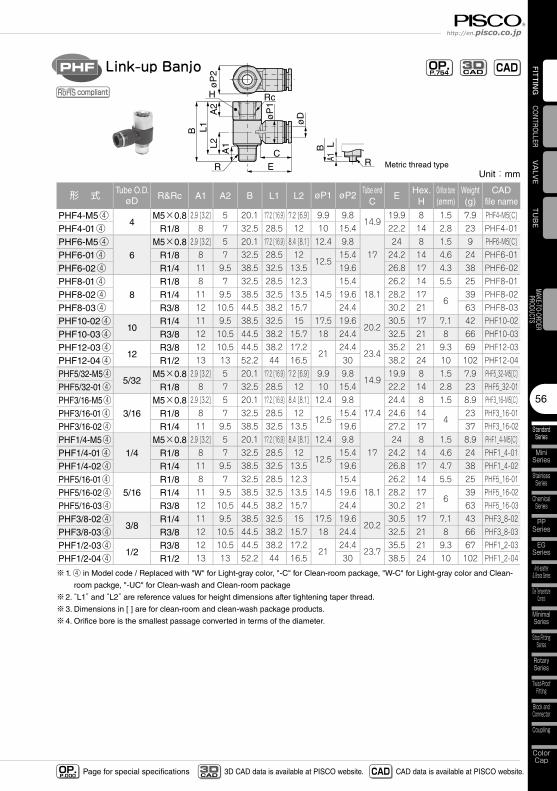
形 式 Tube O.D.øD R&Rc A1 A2 B L1 L2 øP1 øP2 Tube end
CE
Hex.H
Orifice bore(ømm)
Weight(g)
CADfile name
PHF4-M5④4
M5×0.8 2.9 [3.2] 5 20.1 17.2 [16.9] 7.2 [6.9] 9.9 9.814.9
19.9 8 1.5 7.9 PHF4-M5[C]
PHF4-01④ R1/8 8 7 32.5 28.5 12 10 15.4 22.2 14 2.8 23 PHF4-01
PHF6-M5④6
M5×0.8 2.9 [3.2] 5 20.1 17.2 [16.9] 8.4 [8.1] 12.4 9.817
24 8 1.5 9 PHF6-M5[C]
PHF6-01④ R1/8 8 7 32.5 28.5 1212.5
15.4 24.2 14 4.6 24 PHF6-01
PHF6-02④ R1/4 11 9.5 38.5 32.5 13.5 19.6 26.8 17 4.3 38 PHF6-02
PHF8-01④8
R1/8 8 7 32.5 28.5 12.314.5
15.418.1
26.2 14 5.5 25 PHF8-01
PHF8-02④ R1/4 11 9.5 38.5 32.5 13.5 19.6 28.2 176
39 PHF8-02
PHF8-03④ R3/8 12 10.5 44.5 38.2 15.7 24.4 30.2 21 63 PHF8-03
PHF10-02④10
R1/4 11 9.5 38.5 32.5 15 17.5 19.620.2
30.5 17 7.1 42 PHF10-02
PHF10-03④ R3/8 12 10.5 44.5 38.2 15.7 18 24.4 32.5 21 8 66 PHF10-03
PHF12-03④12
R3/8 12 10.5 44.5 38.2 17.221
24.423.4
35.2 21 9.3 69 PHF12-03
PHF12-04④ R1/2 13 13 52.2 44 16.5 30 38.2 24 10 102 PHF12-04
PHF5/32-M5④5/32
M5×0.8 2.9 [3.2] 5 20.1 17.2 [16.9] 7.2 [6.9] 9.9 9.814.9
19.9 8 1.5 7.9 PHF5_32-M5[C]
PHF5/32-01④ R1/8 8 7 32.5 28.5 12 10 15.4 22.2 14 2.8 23 PHF5_32-01
PHF3/16-M5④3/16
M5×0.8 2.9 [3.2] 5 20.1 17.2 [16.9] 8.4 [8.1] 12.4 9.817.4
24.4 8 1.5 8.9 PHF3_16-M5[C]
PHF3/16-01④ R1/8 8 7 32.5 28.5 1212.5
15.4 24.6 144
23 PHF3_16-01
PHF3/16-02④ R1/4 11 9.5 38.5 32.5 13.5 19.6 27.2 17 37 PHF3_16-02
PHF1/4-M5④1/4
M5×0.8 2.9 [3.2] 5 20.1 17.2 [16.9] 8.4 [8.1] 12.4 9.817
24 8 1.5 8.9 PHF1_4-M5[C]
PHF1/4-01④ R1/8 8 7 32.5 28.5 1212.5
15.4 24.2 14 4.6 24 PHF1_4-01
PHF1/4-02④ R1/4 11 9.5 38.5 32.5 13.5 19.6 26.8 17 4.7 38 PHF1_4-02
PHF5/16-01④5/16
R1/8 8 7 32.5 28.5 12.314.5
15.418.1
26.2 14 5.5 25 PHF5_16-01
PHF5/16-02④ R1/4 11 9.5 38.5 32.5 13.5 19.6 28.2 176
39 PHF5_16-02
PHF5/16-03④ R3/8 12 10.5 44.5 38.2 15.7 24.4 30.2 21 63 PHF5_16-03
PHF3/8-02④3/8
R1/4 11 9.5 38.5 32.5 15 17.5 19.620.2
30.5 17 7.1 43 PHF3_8-02
PHF3/8-03④ R3/8 12 10.5 44.5 38.2 15.7 18 24.4 32.5 21 8 66 PHF3_8-03
PHF1/2-03④1/2
R3/8 12 10.5 44.5 38.2 17.221
24.423.7
35.5 21 9.3 67 PHF1_2-03
PHF1/2-04④ R1/2 13 13 52.2 44 16.5 30 38.5 24 10 102 PHF1_2-04
※1. ④ in Model code / Replaced with "W" for Light-gray color, "-C" for Clean-room package, "W-C" for Light-gray color and Clean-
room packge, "-UC" for Clean-wash and Clean-room package
※2. “L1” and “L2” are reference values for height dimensions after tightening taper thread.
※3. Dimensions in [ ] are for clean-room and clean-wash package products.
※4. Orifice bore is the smallest passage converted in terms of the diameter.
Fitting SeriesTube Fitting
StandardSeries
57
FITTING
Page for special specificationsOP.P.000 3D CAD data is available at PISCO website.CAD
3D CAD CAD data is available at PISCO website.
2-ø
D2-
øP
1
2-CE
B L1
AJ
L2
RH
2-øP2
Double BanjoPHW OP.P.754 CADCAD
3D
compliant
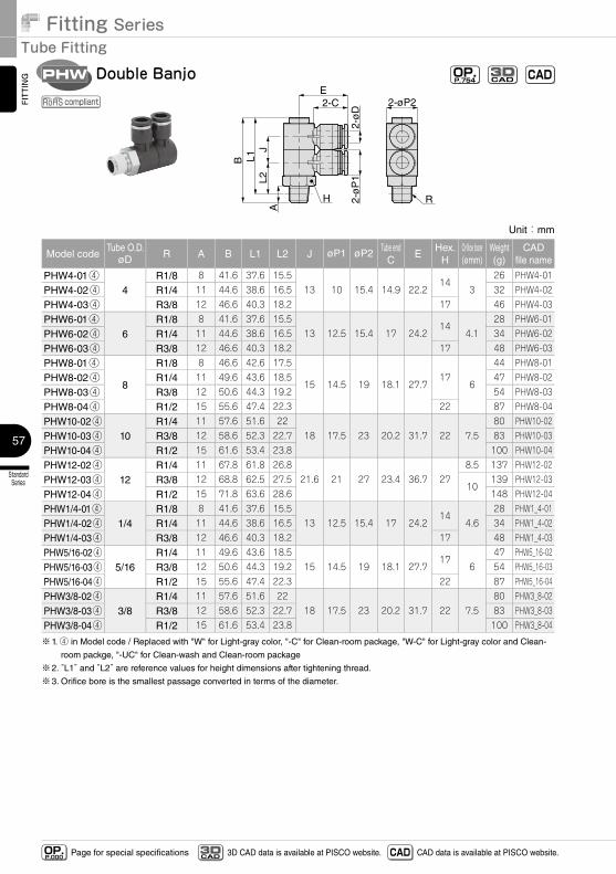
Unit:mm
Model codeTube O.D.
øD R A B L1 L2 J øP1 øP2 Tube endC
EHex.
HOrifice bore(ømm)
Weight(g)
CADfile name
PHW4-01④4
R1/8 8 41.6 37.6 15.513 10 15.4 14.9 22.2
143
26 PHW4-01
PHW4-02④ R1/4 11 44.6 38.6 16.5 32 PHW4-02
PHW4-03④ R3/8 12 46.6 40.3 18.2 17 46 PHW4-03
PHW6-01④6
R1/8 8 41.6 37.6 15.513 12.5 15.4 17 24.2
144.1
28 PHW6-01
PHW6-02④ R1/4 11 44.6 38.6 16.5 34 PHW6-02
PHW6-03④ R3/8 12 46.6 40.3 18.2 17 48 PHW6-03
PHW8-01④
8
R1/8 8 46.6 42.6 17.5
15 14.5 19 18.1 27.717
6
44 PHW8-01
PHW8-02④ R1/4 11 49.6 43.6 18.5 47 PHW8-02
PHW8-03④ R3/8 12 50.6 44.3 19.2 54 PHW8-03
PHW8-04④ R1/2 15 55.6 47.4 22.3 22 87 PHW8-04
PHW10-02④10
R1/4 11 57.6 51.6 2218 17.5 23 20.2 31.7 22 7.5
80 PHW10-02
PHW10-03④ R3/8 12 58.6 52.3 22.7 83 PHW10-03
PHW10-04④ R1/2 15 61.6 53.4 23.8 100 PHW10-04
PHW12-02④12
R1/4 11 67.8 61.8 26.821.6 21 27 23.4 36.7 27
8.5 137 PHW12-02
PHW12-03④ R3/8 12 68.8 62.5 27.510
139 PHW12-03
PHW12-04④ R1/2 15 71.8 63.6 28.6 148 PHW12-04
PHW1/4-01④1/4
R1/8 8 41.6 37.6 15.513 12.5 15.4 17 24.2
144.6
28 PHW1_4-01
PHW1/4-02④ R1/4 11 44.6 38.6 16.5 34 PHW1_4-02
PHW1/4-03④ R3/8 12 46.6 40.3 18.2 17 48 PHW1_4-03
PHW5/16-02④5/16
R1/4 11 49.6 43.6 18.515 14.5 19 18.1 27.7
176
47 PHW5_16-02
PHW5/16-03④ R3/8 12 50.6 44.3 19.2 54 PHW5_16-03
PHW5/16-04④ R1/2 15 55.6 47.4 22.3 22 87 PHW5_16-04
PHW3/8-02④3/8
R1/4 11 57.6 51.6 2218 17.5 23 20.2 31.7 22 7.5
80 PHW3_8-02
PHW3/8-03④ R3/8 12 58.6 52.3 22.7 83 PHW3_8-03
PHW3/8-04④ R1/2 15 61.6 53.4 23.8 100 PHW3_8-04
※1. ④ in Model code / Replaced with "W" for Light-gray color, "-C" for Clean-room package, "W-C" for Light-gray color and Clean-
room packge, "-UC" for Clean-wash and Clean-room package
※2. “L1” and “L2” are reference values for height dimensions after tightening thread.
※3. Orifice bore is the smallest passage converted in terms of the diameter.
58
StandardSeries
MiniSeries
StainlessSeries
ChemicalSeries
PPSeries
EGSeries
Anti-spatter& Brass Series
Die TemperatureControl
MinimalSeries
Stop FittingSeries
RotarySeries
Twist-ProofFitting
Block andConnector
Coupling
ColorCap
FITTING
TUBE
VALVE
CONTROLLERMAKE-TO-ORDERPRODUCTS
http://en.pisco.co.jp
Page for special specificationsOP.P.000 3D CAD data is available at PISCO website.CAD
3D CAD CAD data is available at PISCO website.
Unit:mm
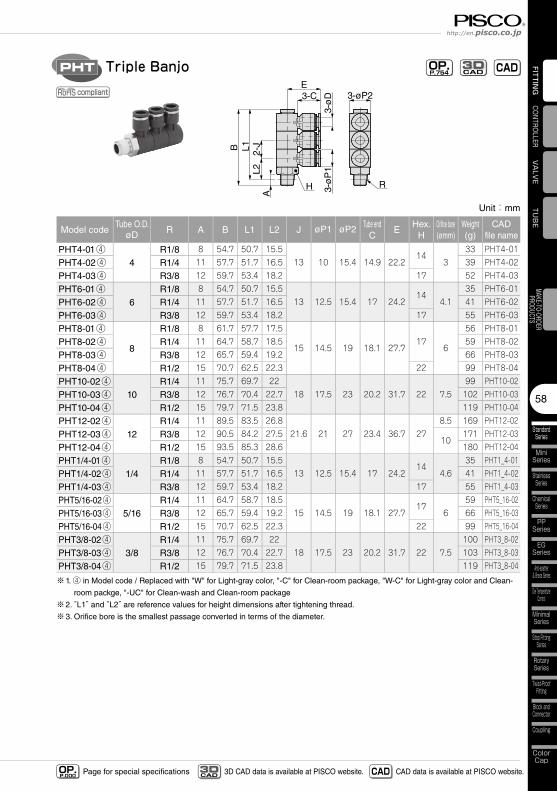
Model codeTube O.D.
øD R A B L1 L2 J øP1 øP2 Tube endC
EHex.
HOrifice bore(ømm)
Weight(g)
CADfile name
PHT4-01④4
R1/8 8 54.7 50.7 15.5 13 10 15.4 14.9 22.2
143
33 PHT4-01
PHT4-02④ R1/4 11 57.7 51.7 16.5 39 PHT4-02
PHT4-03④ R3/8 12 59.7 53.4 18.2 17 52 PHT4-03
PHT6-01④6
R1/8 8 54.7 50.7 15.5 13 12.5 15.4 17 24.2
144.1
35 PHT6-01
PHT6-02④ R1/4 11 57.7 51.7 16.5 41 PHT6-02
PHT6-03④ R3/8 12 59.7 53.4 18.2 17 55 PHT6-03
PHT8-01④
8
R1/8 8 61.7 57.7 17.5
15 14.5 19 18.1 27.7 17
6
56 PHT8-01
PHT8-02④ R1/4 11 64.7 58.7 18.5 59 PHT8-02
PHT8-03④ R3/8 12 65.7 59.4 19.2 66 PHT8-03
PHT8-04④ R1/2 15 70.7 62.5 22.3 22 99 PHT8-04
PHT10-02④10
R1/4 11 75.7 69.7 22 18 17.5 23 20.2 31.7 22 7.5
99 PHT10-02
PHT10-03④ R3/8 12 76.7 70.4 22.7 102 PHT10-03
PHT10-04④ R1/2 15 79.7 71.5 23.8 119 PHT10-04
PHT12-02④12
R1/4 11 89.5 83.5 26.8 21.6 21 27 23.4 36.7 27
8.5 169 PHT12-02
PHT12-03④ R3/8 12 90.5 84.2 27.5 10
171 PHT12-03
PHT12-04④ R1/2 15 93.5 85.3 28.6 180 PHT12-04
PHT1/4-01④1/4
R1/8 8 54.7 50.7 15.5 13 12.5 15.4 17 24.2
144.6
35 PHT1_4-01
PHT1/4-02④ R1/4 11 57.7 51.7 16.5 41 PHT1_4-02
PHT1/4-03④ R3/8 12 59.7 53.4 18.2 17 55 PHT1_4-03
PHT5/16-02④5/16
R1/4 11 64.7 58.7 18.5 15 14.5 19 18.1 27.7
176
59 PHT5_16-02
PHT5/16-03④ R3/8 12 65.7 59.4 19.2 66 PHT5_16-03
PHT5/16-04④ R1/2 15 70.7 62.5 22.3 22 99 PHT5_16-04
PHT3/8-02④3/8
R1/4 11 75.7 69.7 22 18 17.5 23 20.2 31.7 22 7.5
100 PHT3_8-02
PHT3/8-03④ R3/8 12 76.7 70.4 22.7 103 PHT3_8-03
PHT3/8-04④ R1/2 15 79.7 71.5 23.8 119 PHT3_8-04
※1. ④ in Model code / Replaced with "W" for Light-gray color, "-C" for Clean-room package, "W-C" for Light-gray color and Clean-
room packge, "-UC" for Clean-wash and Clean-room package
※2. “L1” and “L2” are reference values for height dimensions after tightening thread.
※3. Orifice bore is the smallest passage converted in terms of the diameter.
RH
B L1
A2-
JL2
3-CE
3-øP2
3-ø
D3-
øP
1
Triple BanjoPHT OP.P.754 CADCAD
3D
compliant
Fitting SeriesTube Fitting
StandardSeries
59
FITTING
Page for special specificationsOP.P.000 3D CAD data is available at PISCO website.CAD
3D CAD CAD data is available at PISCO website.
Unit:mm
Model codeTube O.D.
øD R A B L1 L2 øP1 øP2 Tube endC
J E ød F THex.H
Orifice bore(ømm)
Weight(g)
CADfile name
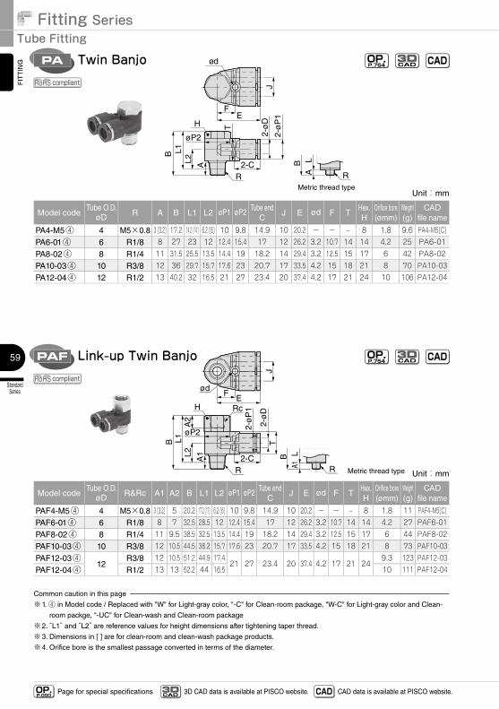
PA4-M5④ 4 M5×0.8 3 [3.2] 17.2 14.2 [14] 6.2 [6] 10 9.8 14.9 10 20.2 - - - 8 1.8 9.6 PA4-M5[C]
PA6-01④ 6 R1/8 8 27 23 12 12.4 15.4 17 12 26.2 3.2 10.7 14 14 4.2 25 PA6-01
PA8-02④ 8 R1/4 11 31.5 25.5 13.5 14.4 19 18.2 14 29.4 3.2 12.5 15 17 6 42 PA8-02
PA10-03④ 10 R3/8 12 36 29.7 15.7 17.6 23 20.7 17 33.5 4.2 15 18 21 8 70 PA10-03
PA12-04④ 12 R1/2 13 40.2 32 16.5 21 27 23.4 20 37.4 4.2 17 21 24 10 106 PA12-04
2-ø
D
2-ø
P1
2-C
E
B L1L2 A
R
H
R
F
J
T
ød
Metric thread type
BA
L
øP2
Twin BanjoPA
Unit:mm
Model codeTube O.D.
øD R&Rc A1 A2 B L1 L2 øP1 øP2 Tube endC
J E ød F THex.H
Orifice bore(ømm)
Weight(g)
CADfile name
PAF4-M5④ 4 M5×0.8 3 [3.2] 5 20.2 17.2 [17] 6.2 [6] 10 9.8 14.9 10 20.2 - - - 8 1.8 11 PAF4-M5[C]
PAF6-01④ 6 R1/8 8 7 32.5 28.5 12 12.4 15.4 17 12 26.2 3.2 10.7 14 14 4.2 27 PAF6-01
PAF8-02④ 8 R1/4 11 9.5 38.5 32.5 13.5 14.4 19 18.2 14 29.4 3.2 12.5 15 17 6 44 PAF8-02
PAF10-03④ 10 R3/8 12 10.5 44.5 38.2 15.7 17.6 23 20.7 17 33.5 4.2 15 18 21 8 73 PAF10-03
PAF12-03④12
R3/8 12 10.5 51.2 44.9 17.421 27 23.4 20 37.4 4.2 17 21 24
9.3 123 PAF12-03
PAF12-04④ R1/2 13 13 52.2 44 16.5 10 111 PAF12-04
Common caution in this page
※1. ④ in Model code / Replaced with "W" for Light-gray color, "-C" for Clean-room package, "W-C" for Light-gray color and Clean-
room packge, "-UC" for Clean-wash and Clean-room package
※2. “L1” and “L2” are reference values for height dimensions after tightening taper thread.
※3. Dimensions in [ ] are for clean-room and clean-wash package products.
※4. Orifice bore is the smallest passage converted in terms of the diameter.
2-ø
DT
2-ø
P1
2-C
E
B L1
A1
R
H
R
F
J
ød
A2
L2
Rc
Metric thread type
BA1
L
øP2
Link-up Twin BanjoPAF
OP.P.754 CADCAD
3D
OP.P.754 CADCAD
3D
compliant
compliant
60
StandardSeries
MiniSeries
StainlessSeries
ChemicalSeries
PPSeries
EGSeries
Anti-spatter& Brass Series
Die TemperatureControl
MinimalSeries
Stop FittingSeries
RotarySeries
Twist-ProofFitting
Block andConnector
Coupling
ColorCap
FITTING
TUBE
VALVE
CONTROLLERMAKE-TO-ORDERPRODUCTS
http://en.pisco.co.jp
Page for special specificationsOP.P.000 3D CAD data is available at PISCO website.CAD
3D CAD CAD data is available at PISCO website.
R
H
B L1
AJ1
L2
4-CE
2-øP2 J2
4-ø
D4-
øP
1
Double Twin BanjoPAW OP.P.754 CADCAD
3D
compliant
Unit:mm
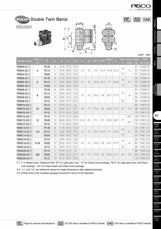
Model codeTube O.D.øD R A B L1 L2 J1 J2 øP1 øP2 Tube end
CE
Hex.H
Orifice bore(ømm)
Weight(g)
CADfile name
PAW4-01④4
R1/8 8 41.6 37.6 15.513 10 10 15.4 14.9 22.2
143
31 PAW4-01
PAW4-02④ R1/4 11 44.6 38.6 16.5 37 PAW4-02
PAW4-03④ R3/8 12 46.6 40.3 18.2 17 51 PAW4-03
PAW6-01④6
R1/8 8 41.6 37.6 15.513 12 12.5 15.4 17 24.2
143.7
35 PAW6-01
PAW6-02④ R1/4 11 44.6 38.6 16.5 40 PAW6-02
PAW6-03④ R3/8 12 46.6 40.3 18.2 17 54 PAW6-03
PAW8-01④
8
R1/8 8 46.6 42.6 17.5
15 14 14.5 19 18.1 27.717
6
54 PAW8-01
PAW8-02④ R1/4 11 49.6 43.6 18.5 56 PAW8-02
PAW8-03④ R3/8 12 50.6 44.3 19.2 64 PAW8-03
PAW8-04④ R1/2 15 55.6 47.4 22.3 22 96 PAW8-04
PAW10-02④10
R1/4 11 57.6 51.6 2218 17 17.5 23 20.2 31.7 22 7.5
95 PAW10-02
PAW10-03④ R3/8 12 58.6 52.3 22.7 98 PAW10-03
PAW10-04④ R1/2 15 61.6 53.4 23.8 115 PAW10-04
PAW12-02④12
R1/4 11 67.8 61.8 26.821.6 20 21 27 23.4 36.7 27
8.5 160 PAW12-02
PAW12-03④ R3/8 12 68.8 62.5 27.59.7
162 PAW12-03
PAW12-04④ R1/2 15 71.8 63.6 28.6 171 PAW12-04
PAW1/4-01④1/4
R1/8 8 41.6 37.6 15.513 12 12.5 15.4 17 24.2
144.1
34 PAW1_4-01
PAW1/4-02④ R1/4 11 44.6 38.6 16.5 40 PAW1_4-02
PAW1/4-03④ R3/8 12 46.6 40.3 18.2 17 54 PAW1_4-03
PAW5/16-02④5/16
R1/4 11 49.6 43.6 18.515 14 14.5 19 18.1 27.7
176
56 PAW5_16-02
PAW5/16-03④ R3/8 12 50.6 44.3 19.2 64 PAW5_16-03
PAW5/16-04④ R1/2 15 55.6 47.4 22.3 22 96 PAW5_16-04
PAW3/8-02④3/8
R1/4 11 57.6 51.6 2218 17 17.5 23 20.2 31.7 22 7.5
96 PAW3_8-02
PAW3/8-03④ R3/8 12 58.6 52.3 22.7 99 PAW3_8-03
PAW3/8-04④ R1/2 15 61.6 53.4 23.8 116 PAW3_8-04
※1. ④ in Model code / Replaced with "W" for Light-gray color, "-C" for Clean-room package, "W-C" for Light-gray color and Clean-
room packge, "-UC" for Clean-wash and Clean-room package
※2. “L1” and “L2” are reference values for height dimensions after tightening thread.
※3. Orifice bore is the smallest passage converted in terms of the diameter.
Fitting SeriesTube Fitting
StandardSeries
61
FITTING
Page for special specificationsOP.P.000 3D CAD data is available at PISCO website.CAD
3D CAD CAD data is available at PISCO website.
Unit:mm
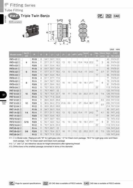
Model codeTube O.D.øD R A B L1 L2 J1 J2 øP1 øP2 Tube end
CE
Hex.H
Orifice bore(ømm)
Weight(g)
CADfile name
PAT4-01④4
R1/8 8 54.7 50.7 15.5 13 10 10 15.4 14.9 22.2
143
40 PAT4-01
PAT4-02④ R1/4 11 57.7 51.7 16.5 46 PAT4-02
PAT4-03④ R3/8 12 59.7 53.4 18.2 17 60 PAT4-03
PAT6-01④6
R1/8 8 54.7 50.7 15.5 13 12 12.5 15.4 17 24.2
143.7
45 PAT6-01
PAT6-02④ R1/4 11 57.7 51.7 16.5 51 PAT6-02
PAT6-03④ R3/8 12 59.7 53.4 18.2 17 65 PAT6-03
PAT8-01④
8
R1/8 8 61.7 57.7 17.5
15 14 14.5 19 18.1 27.7 17
6
71 PAT8-01
PAT8-02④ R1/4 11 64.7 58.7 18.5 73 PAT8-02
PAT8-03④ R3/8 12 65.7 59.4 19.2 81 PAT8-03
PAT8-04④ R1/2 15 70.7 62.5 22.3 22 113 PAT8-04
PAT10-02④10
R1/4 11 75.7 69.7 22 18 17 17.5 23 20.2 31.7 22 7.5
122 PAT10-02
PAT10-03④ R3/8 12 76.7 70.4 22.7 126 PAT10-03
PAT10-04④ R1/2 15 79.7 71.5 23.8 142 PAT10-04
PAT12-02④12
R1/4 11 89.5 83.5 26.8 21.6 20 21 27 23.4 36.7 27
8.5 203 PAT12-02
PAT12-03④ R3/8 12 90.5 84.2 27.5 9.7
205 PAT12-03
PAT12-04④ R1/2 15 93.5 85.3 28.6 214 PAT12-04
PAT1/4-01④1/4
R1/8 8 54.7 50.7 15.5 13 12 12.5 15.4 17 24.2
144.1
45 PAT1_4-01
PAT1/4-02④ R1/4 11 57.7 51.7 16.5 50 PAT1_4-02
PAT1/4-03④ R3/8 12 59.7 53.4 18.2 17 64 PAT1_4-03
PAT5/16-02④5/16
R1/4 11 64.7 58.7 18.5 15 14 14.5 19 18.1 27.7
176
73 PAT5_16-02
PAT5/16-03④ R3/8 12 65.7 59.4 19.2 81 PAT5_16-03
PAT5/16-04④ R1/2 15 70.7 62.5 22.3 22 113 PAT5_16-04
PAT3/8-02④3/8
R1/4 11 75.7 69.7 22 18 17 17.5 23 20.2 31.7 22 7.5
124 PAT3_8-02
PAT3/8-03④ R3/8 12 76.7 70.4 22.7 125 PAT3_8-03
PAT3/8-04④ R1/2 15 79.7 71.5 23.8 143 PAT3_8-04
※1. ④ in Model code / Replaced with "W" for Light-gray color, "-C" for Clean-room package, "W-C" for Light-gray color and Clean-
room packge, "-UC" for Clean-wash and Clean-room package
※2. “L1” and “L2” are reference values for height dimensions after tightening thread.
※3. Orifice bore is the smallest passage converted in terms of the diameter.
R
H
B L1
A2-
J1L2
6-CE
3-øP2 J2
6-ø
D6-
øP
1
Triple Twin BanjoPAT OP.P.754 CADCAD
3D
compliant
62
StandardSeries
MiniSeries
StainlessSeries
ChemicalSeries
PPSeries
EGSeries
Anti-spatter& Brass Series
Die TemperatureControl
MinimalSeries
Stop FittingSeries
RotarySeries
Twist-ProofFitting
Block andConnector
Coupling
ColorCap
FITTING
TUBE
VALVE
CONTROLLERMAKE-TO-ORDERPRODUCTS
http://en.pisco.co.jp
Page for special specificationsOP.P.000 3D CAD data is available at PISCO website.CAD
3D CAD CAD data is available at PISCO website.
Unit:mm
Model codeTube O.D.øD
R A B L øPTube end
CE
Hex.H
Orifice bore(ømm)
Weight(g)
CADfile name
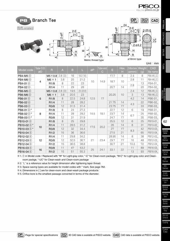
PB4-M5④
4
M5×0.8 2.8 [3] 16 18.2 [18]
10 14.9
17.7 8 2.4 8 PB4-M5_[C]PB4-M6④ M6×1 3.8 20 21.2
18.7 102.8 11 PB4-M6_[C]
PB4-01④ R1/8 8 22 232.8
13 PB4-01_PB4-02④ R1/4 11 29 28 20.7 14 20 PB4-02_PB6-M5④
6
M5×0.8 2.8 [3] 19.5 23 [22.8]
12.5 1720.25 10
2.4 12 PB6-M5_[C]PB6-M6④ M6×1 3.8 20.5 23 3 13 PB6-M6_[C]PB6-01④ R1/8 8 22.5 24.8 4.2 14 PB6-01_PB6-02④ R1/4 11 28 28.2 21.75 14
4.322 PB6-02_
PB6-03④ R3/8 12 31.5 31.4 23.75 17 33 PB6-03_PB8-01④ *
8R1/8 8 24 27.3
14.5 18.122.7 12 6 19 PB8-01_
PB8-02④ * R1/4 11 28 29.2 23.7 146.7
25 PB8-02_PB8-03④ * R3/8 12 31 31.9 24.7 17 35 PB8-03_PB10-01④
10
R1/8 8 25 29.8
17.5 20.2
25.5 12 6 25 PB10-01_PB10-02④ * R1/4 11 28.5 31.2 26 14 8 31 PB10-02_PB10-03④ * R3/8 12 32 34.4 27 17
8.342 PB10-03_
PB10-04④ R1/2 15 36 36.6 27.5 21 65 PB10-04_PB12-02④
12R1/4 11 29.8 34.2
21 23.428.95 14 8 38 PB12-02_
PB12-03④ R3/8 12 32.5 36.7 29.7 17 10 48 PB12-03_PB12-04④ R1/2 15 36.5 38.8 30.7 21 10.3 72 PB12-04_PB16-03④
16R3/8 11 47 53.2
25 24.1 33.1 2211 89 PB16-03_
PB16-04④ R1/2 15 51 55.3 13 93 PB16-04_
※1. ④ in Model code / Replaced with "W" for Light-gray color, "-C" for Clean-room package, "W-C" for Light-gray color and Clean-
room packge, "-UC" for Clean-wash and Clean-room package
※2. “L” is a reference value for height dimension after tightening taper thread.
※3. Space saving types are available for model codes with * mark. See page 762.※4. Dimensions in [ ] are for clean-room and clean-wash package products※5. Orifice bore is the smallest passage converted in terms of the diameter.
2-C2-E
2-ø
P
2-ø
D
R
H
B
L
A
ø16mm type
2-ø4.2
12
24
2-25.6
Metric thread type
2-ø
D
RH
2-ø
P
LB
2-C2-E
A
ALB
R
Branch TeePB OP.P.754 CADCAD
3D
compliant
Fitting SeriesTube Fitting
StandardSeries
63
FITTING
Page for special specificationsOP.P.000 3D CAD data is available at PISCO website.CAD
3D CAD CAD data is available at PISCO website.
2-C2-E
2-ø
P
2-ø
D
R
H
B
L
A
ø16mm type
2-ø4.2
12
24
2-25.6
Metric thread type
2-ø
D
RH
2-ø
P
LB
2-C2-E
A
ALB
R
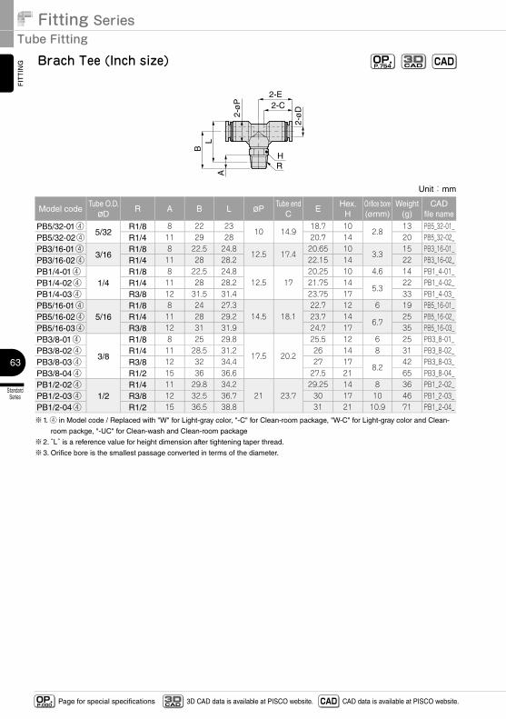
Brach Tee (Inch size) OP.P.754 CADCAD
3D
Unit:mm
Model codeTube O.D.øD
R A B L øPTube end
CE
Hex.H
Orifice bore(ømm)
Weight(g)
CADfile name
PB5/32-01④5/32
R1/8 8 22 2310 14.9
18.7 102.8
13 PB5_32-01_PB5/32-02④ R1/4 11 29 28 20.7 14 20 PB5_32-02_PB3/16-01④
3/16R1/8 8 22.5 24.8
12.5 17.420.65 10
3.315 PB3_16-01_
PB3/16-02④ R1/4 11 28 28.2 22.15 14 22 PB3_16-02_PB1/4-01④
1/4R1/8 8 22.5 24.8
12.5 1720.25 10 4.6 14 PB1_4-01_
PB1/4-02④ R1/4 11 28 28.2 21.75 145.3
22 PB1_4-02_PB1/4-03④ R3/8 12 31.5 31.4 23.75 17 33 PB1_4-03_PB5/16-01④
5/16R1/8 8 24 27.3
14.5 18.122.7 12 6 19 PB5_16-01_
PB5/16-02④ R1/4 11 28 29.2 23.7 146.7
25 PB5_16-02_PB5/16-03④ R3/8 12 31 31.9 24.7 17 35 PB5_16-03_PB3/8-01④
3/8
R1/8 8 25 29.8
17.5 20.2
25.5 12 6 25 PB3_8-01_PB3/8-02④ R1/4 11 28.5 31.2 26 14 8 31 PB3_8-02_PB3/8-03④ R3/8 12 32 34.4 27 17
8.242 PB3_8-03_
PB3/8-04④ R1/2 15 36 36.6 27.5 21 65 PB3_8-04_PB1/2-02④
1/2R1/4 11 29.8 34.2
21 23.729.25 14 8 36 PB1_2-02_
PB1/2-03④ R3/8 12 32.5 36.7 30 17 10 46 PB1_2-03_PB1/2-04④ R1/2 15 36.5 38.8 31 21 10.9 71 PB1_2-04_
※1. ④ in Model code / Replaced with "W" for Light-gray color, "-C" for Clean-room package, "W-C" for Light-gray color and Clean-
room packge, "-UC" for Clean-wash and Clean-room package
※2. “L” is a reference value for height dimension after tightening taper thread.
※3. Orifice bore is the smallest passage converted in terms of the diameter.
64
StandardSeries
MiniSeries
StainlessSeries
ChemicalSeries
PPSeries
EGSeries
Anti-spatter& Brass Series
Die TemperatureControl
MinimalSeries
Stop FittingSeries
RotarySeries
Twist-ProofFitting
Block andConnector
Coupling
ColorCap
FITTING
TUBE
VALVE
CONTROLLERMAKE-TO-ORDERPRODUCTS
http://en.pisco.co.jp
Page for special specificationsOP.P.000 3D CAD data is available at PISCO website.CAD
3D CAD CAD data is available at PISCO website.
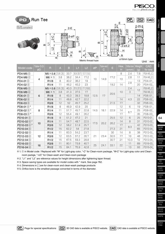
Run TeePD OP.P.754 CADCAD
3D
compliant
Unit:mm
Model codeTube O.D.øD
R A B L1 L2 øPTube end
CE
Hex.H
Orifice bore(ømm)
Weight(g)
CADfile name
PD4-M5④
4
M5×0.8 2.8 [3] 33.7 30.9 [30.7] 13.7 [13.5]
10 14.917.2
8 2.4 7.8 PD4-M5_[C]PD4-M6④ M6×1 3.8 38.2 34.4 17.2
102.8 11 PD4-M6_[C]
PD4-01④ R1/8 8 40.2 36.2 192.8
13 PD4-01_PD4-02④ R1/4 11 46.2 40.2 23 19.2 14 20 PD4-02_PD6-M5④
6
M5×0.8 2.8 [3] 40.3 37.5 [37.3] 17 [16.8]
12.5 1720.5
102.4
12PD6-M5_[C]
PD6-M6④ M6×1 3.8 41.3 37.5 17 3 PD6-M6_[C]PD6-01④ R1/8 8 43.3 39.3 18.8
4.314 PD6-01_
PD6-02④ R1/4 11 48.8 42.7 22.2 14 22 PD6-02_PD6-03④ R3/8 12 52 45.7 25.2 21.5 17 32 PD6-03_PD8-01④ *
8R1/8 8 46.9 42.9 20
14.5 18.1 22.912 6 19 PD8-01_
PD8-02④ * R1/4 11 51.7 45.7 22.8 146.7
25 PD8-02_PD8-03④ * R3/8 12 55.4 49.1 26.2 17 35 PD8-03_PD10-01④
10
R1/8 8 51.2 47.2 21
17.5 20.2
25.5 12 6 25 PD10-01_PD10-02④ * R1/4 11 54.7 48.7 22.5
26.214 8 31 PD10-02_
PD10-03④ * R3/8 12 58.2 51.9 25.7 178.3
42 PD10-03_PD10-04④ R1/2 15 62.2 54 27.8 27.3 21 65 PD10-04_PD12-02④
12R1/4 11 60.3 54.2 23.7
21 23.430 14 8 38 PD12-02_
PD12-03④ R3/8 12 63.5 57.2 26.7 30.5 17 10 48 PD12-03_PD12-04④ R1/2 15 67.5 59.3 28.8 30.7 21 10.3 72 PD12-04_PD16-03④
16R3/8 11 80.1 73.8 40.7
25 24.1 33.1 2211 89 PD16-03_
PD16-04④ R1/2 15 84.1 75.9 42.8 13 93 PD16-04_
※1. ④ in Model code / Replaced with "W" for Light-gray color, "-C" for Clean-room package, "W-C" for Light-gray color and Clean-
room packge, "-UC" for Clean-wash and Clean-room package
※2. “L1” and “L2” are reference values for height dimensions after tightening taper thread.
※3. Space saving types are available for model codes with * mark. See page 762.※4. Dimensions in [ ] are for clean-room and clean-wash package products※5. Orifice bore is the smallest passage converted in terms of the diameter.
2-ø
D
RH
2-øP
L1B
2-C
L2
2-E
A
Metric thread type
ALB
R
2-ø
D
Rø16mm type
2-C
L2
B L1
A
E12 2-25.6
24
2-ø4.2
2-ø
P
H
Fitting SeriesTube Fitting
StandardSeries
65
FITTING
Page for special specificationsOP.P.000 3D CAD data is available at PISCO website.CAD
3D CAD CAD data is available at PISCO website.
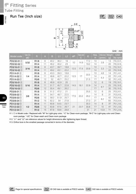
Run Tee (Inch size) OP.P.754 CADCAD
3D
Unit:mm
Model codeTube O.D.øD
R A B L1 L2 øPTube end
CE
Hex.H
Orifice bore(ømm)
Weight(g)
CADfile name
PD5/32-01④5/32
R1/8 8 40.2 36.2 1910 14.9
17.2 102.8
13 PD5_32-01_PD5/32-02④ R1/4 11 46.2 40.2 23 19.2 14 20 PD5_32-02_PD3/16-01④
3/16R1/8 8 43.7 39.7 18.8
12.5 17.4 20.910
3.315 PD3_16-01_
PD3/16-02④ R1/4 11 49.2 43.1 22.2 14 22 PD3_16-02_PD1/4-01④
1/4R1/8 8 43.3 39.3 18.8
12.5 1720.5
10 4.6 14 PD1_4-01_PD1/4-02④ R1/4 11 48.8 42.7 22.2 14
5.322 PD1_4-02_
PD1/4-03④ R3/8 12 52 45.7 25.2 21.5 17 32 PD1_4-03_PD5/16-01④
5/16R1/8 8 46.9 42.9 20
14.5 18.1 22.912 6 19 PD5_16-01_
PD5/16-02④ R1/4 11 51.7 45.7 22.8 146.7
25 PD5_16-02_PD5/16-03④ R3/8 12 55.4 49.1 26.2 17 35 PD5_16-03_PD3/8-01④
3/8
R1/8 8 51.2 47.2 21
17.5 20.2
25.5 12 6 25 PD3_8-01_PD3/8-02④ R1/4 11 54.7 48.7 22.5
26.214 8 31 PD3_8-02_
PD3/8-03④ R3/8 12 58.2 51.9 25.7 178.2
42 PD3_8-03_PD3/8-04④ R1/2 15 62.2 54 27.8 27.3 21 65 PD3_8-04_PD1/2-02④
1/2R1/4 11 60.6 54.5 23.7
21 23.730.3 14 8 37 PD1_2-02_
PD1/2-03④ R3/8 12 63.8 57.5 26.7 30.8 17 10 47 PD1_2-03_PD1/2-04④ R1/2 15 67.8 59.6 28.8 31 21 10.9 71 PD1_2-04_
※1. ④ in Model code / Replaced with "W" for Light-gray color, "-C" for Clean-room package, "W-C" for Light-gray color and Clean-
room packge, "-UC" for Clean-wash and Clean-room package
※2. “L1” and “L2” are reference values for height dimensions after tightening taper thread.
※3. Orifice bore is the smallest passage converted in terms of the diameter.
2-ø
D
RH
2-øP
L1B
2-C
L2
2-E
A
Metric thread type
ALB
R
2-ø
D
Rø16mm type
2-C
L2
B L1
A
E12 2-25.6
24
2-ø4.2
2-ø
P
H
66
StandardSeries
MiniSeries
StainlessSeries
ChemicalSeries
PPSeries
EGSeries
Anti-spatter& Brass Series
Die TemperatureControl
MinimalSeries
Stop FittingSeries
RotarySeries
Twist-ProofFitting
Block andConnector
Coupling
ColorCap
FITTING
TUBE
VALVE
CONTROLLERMAKE-TO-ORDERPRODUCTS
http://en.pisco.co.jp
Page for special specificationsOP.P.000 3D CAD data is available at PISCO website.CAD
3D CAD CAD data is available at PISCO website.
Metric thread type ø16mm type
RH
LB
2-C
J2-øD
A
ALB
R
2-øP
2-øD
ø4.5
2-C
22.1
B LA
J
25
R
H
2-øP
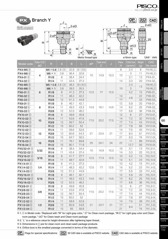
Branch YPX OP.P.754 CADCAD
3D
compliant
Unit:mm
Model codeTube O.D.øD
R A B L øPTube end
CJ
Hex.H
Orifice bore(ømm)
Weight(g)
CADfile name
PX4-M5④
4
M5×0.8 2.8 [3] 32.9 30.1 [29.9]
10 14.9 10.3
8 2.4 8 PX4-M5_[C]PX4-M6④ M6×1 3.8 36.4 32.6
103 11 PX4-M6_[C]
PX4-01④ R1/8 8 38.4 34.4 3.1 13 PX4-01_PX4-02④ R1/4 11 43.4 37.4 14 3.3 20 PX4-02_PX6-M5④
6
M5×0.8 2.8 [3] 38.3 35.5 [35.3]
12.5 17 12.510
2.413
PX6-M5_[C]PX6-M6④ M6×1 3.8 39.3 35.5 3 PX6-M6_[C]PX6-01④ R1/8 8 41.3 37.3 4.2 15 PX6-01_PX6-02④ R1/4 11 48.3 42.2 14
4.822 PX6-02_
PX6-03④ R3/8 12 51.3 44.9 17 33 PX6-03_PX8-01④
8R1/8 8 46.1 42.1
14.5 18.1 14.512 5.9 20 PX8-01_
PX8-02④ R1/4 11 49.3 43.3 14 6.2 25 PX8-02_PX8-03④ R3/8 12 52.5 46.2 17 6.6 36 PX8-03_PX10-01④
10
R1/8 8 49.8 45.8
17.5 20.2 17.5
12 6 27 PX10-01_PX10-02④ R1/4 11 53.6 47.6 14 7.2 32 PX10-02_PX10-03④ R3/8 12 56.7 50.4 17 7.4 43 PX10-03_PX10-04④ R1/2 15 60.2 52 21 7.8 66 PX10-04_PX12-02④
12R1/4 11 58.6 52.6
21 23.4 2114 7.5 40 PX12-02_
PX12-03④ R3/8 12 60.6 54.3 17 8.4 51 PX12-03_PX12-04④ R1/2 15 64.7 56.5 21 8.3 74 PX12-04_PX16-03④
16R3/8 11 76.1 69.8
25 24.1 24 2211 89 PX16-03_
PX16-04④ R1/2 15 80.1 71.9 12.7 93 PX16-04_PX5/32-01④
5/32R1/8 8 38.4 34.4
10 14.9 10.310 3.1 13 PX5_32-01_
PX5/32-02④ R1/4 11 43.4 37.4 14 3.3 20 PX5_32-02_PX3/16-01④
3/16R1/8 8 41.7 37.7
12.5 17.4 12.510 4.2 15 PX3_16-01_
PX3/16-02④ R1/4 11 48.7 42.6 14 5.1 23 PX3_16-02_PX1/4-01④
1/4R1/8 8 41.3 37.3
12.5 17 12.510 4.2 15 PX1_4-01_
PX1/4-02④ R1/4 11 48.3 42.2 14 5.2 22 PX1_4-02_PX1/4-03④ R3/8 12 51.3 44.9 17 5.5 33 PX1_4-03_PX5/16-01④
5/16R1/8 8 46.1 42.1
14.5 18.1 14.512 5.9 20 PX5_16-01_
PX5/16-02④ R1/4 11 49.3 43.3 14 6.2 25 PX5_16-02_PX5/16-03④ R3/8 12 52.5 46.2 17 6.6 36 PX5_16-03_PX3/8-01④
3/8
R1/8 8 49.8 45.8
17.5 20.2 17.5
12 6 27 PX3_8-01_PX3/8-02④ R1/4 11 53.6 47.6 14 7.2 33 PX3_8-02_PX3/8-03④ R3/8 12 56.7 50.4 17 7.4 44 PX3_8-03_PX3/8-04④ R1/2 15 60.2 52 21 7.8 67 PX3_8-04_PX1/2-02④
1/2R1/4 11 58.9 52.9
21 23.7 2114 7.5 39 PX1_2-02_
PX1/2-03④ R3/8 12 60.9 54.6 178.4
51 PX1_2-03_PX1/2-04④ R1/2 15 65 56.8 21 74 PX1_2-04_
※1. ④ in Model code / Replaced with "W" for Light-gray color, "-C" for Clean-room package, "W-C" for Light-gray color and Clean-
room packge, "-UC" for Clean-wash and Clean-room package
※2. “L” is a reference value for height dimension after tightening taper thread.
※3. Dimensions in [ ] are for clean-room and clean-wash package products.
※4. Orifice bore is the smallest passage converted in terms of the diameter.
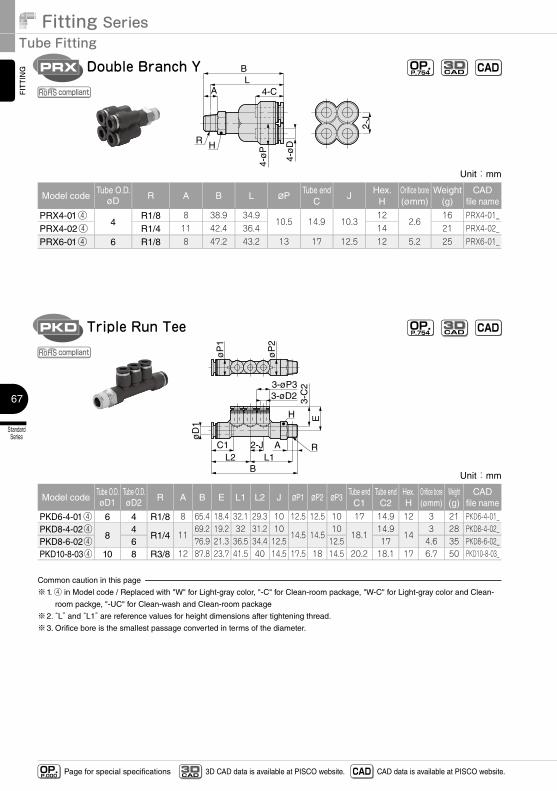
Fitting SeriesTube Fitting
StandardSeries
67
FITTING
Page for special specificationsOP.P.000 3D CAD data is available at PISCO website.CAD
3D CAD CAD data is available at PISCO website.
Unit:mm
Model codeTube O.D.øD1
Tube O.D.øD2 R A B E L1 L2 J øP1 øP2 øP3
Tube endC1
Tube endC2
Hex.H
Orifice bore(ømm)
Weight(g)
CADfile name
PKD6-4-01④ 6 4 R1/8 8 65.4 18.4 32.1 29.3 10 12.5 12.5 10 17 14.9 12 3 21 PKD6-4-01_PKD8-4-02④
84
R1/4 1169.2 19.2 32 31.2 10
14.5 14.510
18.114.9
143 28 PKD8-4-02_
PKD8-6-02④ 6 76.9 21.3 36.5 34.4 12.5 12.5 17 4.6 35 PKD8-6-02_PKD10-8-03④ 10 8 R3/8 12 87.8 23.7 41.5 40 14.5 17.5 18 14.5 20.2 18.1 17 6.7 50 PKD10-8-03_
Common caution in this page
※1. ④ in Model code / Replaced with "W" for Light-gray color, "-C" for Clean-room package, "W-C" for Light-gray color and Clean-
room packge, "-UC" for Clean-wash and Clean-room package
※2. “L” and “L1” are reference values for height dimensions after tightening thread.
※3. Orifice bore is the smallest passage converted in terms of the diameter.
C1 2-JL1L2
A R
H
B
øD
1
3-øD23-øP3
3-C
2E
øP
1
øP
2
Triple Run TeePKD OP.P.754 CADCAD
3D
compliant
4-CA
BL
R H
4-ø
P
4-ø
D
2-J
Double Branch YPRX OP.P.754 CADCAD
3D
compliant
Unit:mm
Model codeTube O.D.
øD R A B L øPTube end
CJ
Hex.H
Orifice bore(ømm)
Weight(g)
CADfile name
PRX4-01④4
R1/8 8 38.9 34.910.5 14.9 10.3
122.6
16 PRX4-01_
PRX4-02④ R1/4 11 42.4 36.4 14 21 PRX4-02_
PRX6-01④ 6 R1/8 8 47.2 43.2 13 17 12.5 12 5.2 25 PRX6-01_
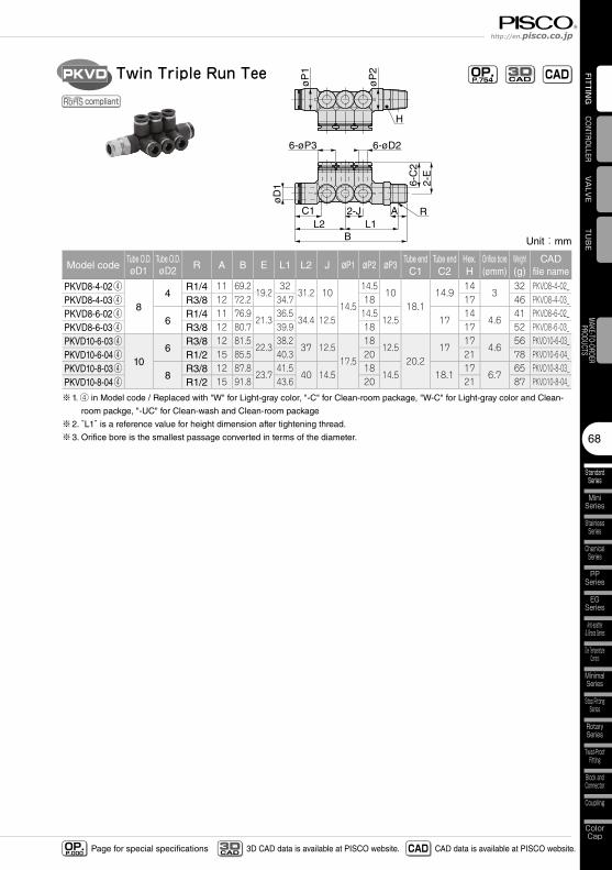
68
StandardSeries
MiniSeries
StainlessSeries
ChemicalSeries
PPSeries
EGSeries
Anti-spatter& Brass Series
Die TemperatureControl
MinimalSeries
Stop FittingSeries
RotarySeries
Twist-ProofFitting
Block andConnector
Coupling
ColorCap
FITTING
TUBE
VALVE
CONTROLLERMAKE-TO-ORDERPRODUCTS
http://en.pisco.co.jp
Page for special specificationsOP.P.000 3D CAD data is available at PISCO website.CAD
3D CAD CAD data is available at PISCO website.
Unit:mm
Model codeTube O.D.øD1
Tube O.D.øD2 R A B E L1 L2 J øP1 øP2 øP3
Tube endC1
Tube endC2
Hex.H
Orifice bore(ømm)
Weight(g)
CADfile name
PKVD8-4-02④
84
R1/4 11 69.219.2
3231.2 10
14.5
14.510
18.114.9
143
32 PKVD8-4-02_PKVD8-4-03④ R3/8 12 72.2 34.7 18 17 46 PKVD8-4-03_PKVD8-6-02④
6R1/4 11 76.9
21.336.5
34.4 12.514.5
12.5 1714
4.641 PKVD8-6-02_
PKVD8-6-03④ R3/8 12 80.7 39.9 18 17 52 PKVD8-6-03_PKVD10-6-03④
106
R3/8 12 81.522.3
38.237 12.5
17.5
1812.5
20.217
174.6
56 PKVD10-6-03_PKVD10-6-04④ R1/2 15 85.5 40.3 20 21 78 PKVD10-6-04_PKVD10-8-03④
8R3/8 12 87.8
23.741.5
40 14.518
14.5 18.117
6.765 PKVD10-8-03_
PKVD10-8-04④ R1/2 15 91.8 43.6 20 21 87 PKVD10-8-04_
※1. ④ in Model code / Replaced with "W" for Light-gray color, "-C" for Clean-room package, "W-C" for Light-gray color and Clean-
room packge, "-UC" for Clean-wash and Clean-room package
※2. “L1” is a reference value for height dimension after tightening thread.
※3. Orifice bore is the smallest passage converted in terms of the diameter.
B
6-øD26-øP3
C1 2-JL2 L1
A R
øD
1 2-E
6-C
2
H
øP
1
øP
2Twin Triple Run TeePKVD OP.P.754 CADCAD
3D
compliant
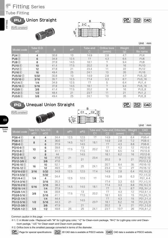
Fitting SeriesTube Fitting
StandardSeries
69
FITTING
Page for special specificationsOP.P.000 3D CAD data is available at PISCO website.CAD
3D CAD CAD data is available at PISCO website.
Unit:mm
Model codeTube O.D.
øD1Tube O.D.
øD2 B øP1 øP2 Tube endC1
Tube endC2
Orifice bore(ømm)
Weight(g)
CADfile name
PG6-4④ 6 4 34.4 12.5 12.5 17 14.9 2.8 6.4 PG6-4PG8-4④
84 36.6
14.510.7
18.114.9 2.8 7.2 PG8-4
PG8-6④ 6 37.9 14.5 17 4.3 8.8 PG8-6PG10-6④
106 39.8
17.513
20.217 4.3 12 PG10-6
PG10-8④ 8 41.1 17.5 18.1 6.5 14 PG10-8PG12-8④
128 44
2114.5
23.418.1 6.2 16 PG12-8
PG12-10④ 10 47.621 20.2 9 21
PG12-10PG12-3/8④ 3/8 47.6 PG12-3_8PG16-10④
1610 52.1
25 25 24.120.7 8.4 35 PG16-10
PG16-12④ 12 49.5 23.4 10 27 PG16-12PG3/16-5/32④ 3/16 5/32 34.8 12.5 12.5 17.4 14.9 2.8 6.4 PG3_16-5_32PG1/4-5/32④
1/45/32 34.4
12.5 12.5 1714.9 2.8 6.3
PG1_4-5_32PG1/4-4④ 4 PG1_4-4PG1/4-3/16④ 3/16 35.3 17.4 3.3 6.5 PG1_4-3_16PG5/16-3/16④
5/163/16 38.3
14.5 14.5 18.117.4 3.3 8.8 PG5_16-3_16
PG5/16-1/4④ 1/4 37.9 17 5 8.7 PG5_16-1_4PG3/8-1/4④
3/81/4 39.8
17.513
20.217 4.3 12 PG3_8-1_4
PG3/8-5/16④ 5/16 41.1 17.5 18.1 6.5 15 PG3_8-5_16PG1/2-1/4④
1/21/4 44.4
2114.5
23.717 4.3 15 PG1_2-1_4
PG1/2-5/16④ 5/16 44.3 18.1 6.2 16 PG1_2-5_16PG1/2-3/8④ 3/8 47.9 21 20.2 9 21 PG1_2-3_8PG5/8-1/2④ 5/8 1/2 49.8 25 25 24.1 23.7 10.7 26 PG5_8-1_2
Common caution in this page
※1. ④ in Model code / Replaced with "W" for Light-gray color, "-C" for Clean-room package, "W-C" for Light-gray color and Clean-
room packge, "-UC" for Clean-wash and Clean-room package
※2. Orifice bore is the smallest passage converted in terms of the diameter.
2-ø
D2-CB
øP
øD
2ø
P2
øD
1ø
P1
C1 C2B
Union Straight
Unequal Union Straight
PU
PG
OP.P.754 CAD
OP.P.754 CAD
CAD3D
CAD3D
compliant
compliant
Unit:mm
Model codeTube O.D.
øD B øP Tube endC
Orifice bore(ømm)
Weight(g)
CADfile name
PU4④ 4 30.8 10 14.9 2.8 4.7 PU4PU6④ 6 34.9 12.5 17 4.3 6.5 PU6PU8④ 8 37.8 14.5 18.1 7 9.4 PU8PU10④ 10 41.4 17.5 20.2 9 16 PU10PU12④ 12 47.8 21 23.4 11 22 PU12PU16④ 16 49.4 25 24.1 13 26 PU16PU5/32④ 5/32 30.8 10 14.9 2.8 4.7 PU5_32PU3/16④ 3/16 35.7 12.5 17.4 3.3 6.7 PU3_16PU1/4④ 1/4 34.9 12.5 17 5 6.4 PU1_4PU5/16④ 5/16 37.8 14.5 18.1 7 9.4 PU5_16PU3/8④ 3/8 41.4 17.5 20.2 9 16 PU3_8PU1/2④ 1/2 48.4 21 23.7 11 21 PU1_2PU5/8④ 5/8 49.4 25 24.1 13 26 PU5_8
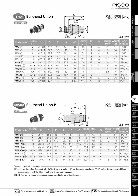
70
StandardSeries
MiniSeries
StainlessSeries
ChemicalSeries
PPSeries
EGSeries
Anti-spatter& Brass Series
Die TemperatureControl
MinimalSeries
Stop FittingSeries
RotarySeries
Twist-ProofFitting
Block andConnector
Coupling
ColorCap
FITTING
TUBE
VALVE
CONTROLLERMAKE-TO-ORDERPRODUCTS
http://en.pisco.co.jp
Page for special specificationsOP.P.000 3D CAD data is available at PISCO website.CAD
3D CAD CAD data is available at PISCO website.
2-ø
D
2-H
øP
BE
2-CM
A2-T
Bulkhead UnionPM OP.P.754 CADCAD
3D
compliant
Unit:mm
Model codeTube O.D.
øD M B E A øPTube end
CHex.
HT
Orifice bore(ømm)
Weight(g)
CADfile name
PM4④ 4 M12×1 30.8 9.5 14.8 10.8 14.9 14 4 3 11 PM4_PM6④ 6 M14×1 34.9 9.5 19 12.5 17 17 4 5 16 PM6_PM8④ 8 M16×1 37.4 10.5 19.4 14.6 18.2 19 4 7 19 PM8_PM10④ 10 M20×1 42.4 11.9 21.6 18.5 20.7 24 5 9 35 PM10_PM12④ 12 M22×1 47.6 13.2 24.2 20.4 23.3 27 6 11 52 PM12_PM16④ 16 M28×1.5 50.6 13.2 27.2 25.5 24.8 32 6 15 73 PM16_PM5/32④ 5/32 M12×1 30.8 9.5 14.8 10.8 14.9 14 4 3 10 PM5_32_PM3/16④ 3/16 M14×1 35.7 9.9 19 12.5 17.4 17 4 4 16 PM3_16_PM1/4④ 1/4 M14×1 34.9 9.5 19 12.5 17 17 4 5.3 16 PM1_4_PM5/16④ 5/16 M16×1 37.4 10.5 19.4 14.6 18.2 19 4 7 19 PM5_16_PM3/8④ 3/8 M20×1 42.4 11.9 21.6 18.5 20.7 24 5 8.5 36 PM3_8_PM1/2④ 1/2 M22×1 47.2 13 24.2 20.4 23.1 27 6 11.7 51 PM1_2_
Unit:mm
Model codeTube O.D.
øD M B E A øP øSTube end
CHex.
HG
Orifice bore(ømm)
Weight(g)
CADfile name
PMP4④ 4 M12×1.5 31.4 9.2 12 10 16 14.9 14 5 3 6.8 PMP4PMP6④ 6 M14×1.5 35.5 9.8 15 12.3 19 17 17 5 4.9 9.6 PMP6PMP8④ 8 M16×1.5 38.4 10.7 15.5 14.2 22 18.1 19 6 7 14 PMP8PMP10④ 10 M20×2 43 13 18.5 17.5 27.5 20.7 24 6 8 23 PMP10PMP12④ 12 M24×2 48.4 13.2 20.5 21 31 23.4 27 6 11 32 PMP12PMP5/32④ 5/32 M12×1.5 31.4 9.2 12 10 16 14.9 14 5 3 6.8 PMP5_32PMP1/4④ 1/4 M14×1.5 35.5 9.8 15 12.3 19 17 17 5 5 9.5 PMP1_4PMP5/16④ 5/16 M16×1.5 38.4 10.7 15.5 14.2 22 18.1 19 6 7 14 PMP5_16PMP3/8④ 3/8 M20×2 43 13 18.5 17.5 27.5 20.7 24 6 8 24 PMP3_8
Common caution in this page
※1. ④ in Model code / Replaced with "W" for Light-gray color, "-C" for Clean-room package, "W-C" for Light-gray color and Clean-
room packge, "-UC" for Clean-wash and Clean-room package
※2. Orifice bore is the smallest passage converted in terms of the diameter.
øS
øP
2-C M H 2-ø
D
BA
GE
Bulkhead Union PPMP OP.P.754 CADCAD
3D
compliant
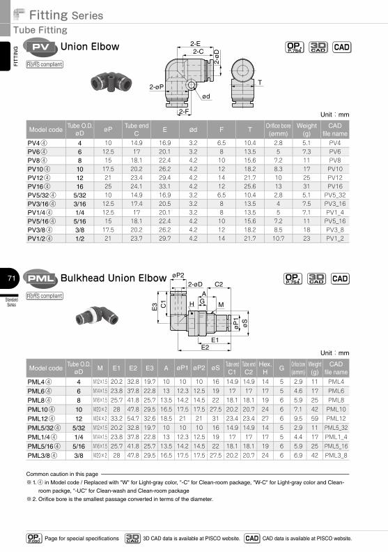
Fitting SeriesTube Fitting
StandardSeries
71
FITTING
Page for special specificationsOP.P.000 3D CAD data is available at PISCO website.CAD
3D CAD CAD data is available at PISCO website.
2-ø
D
2-øPT
2-C2-E
2-F
ød
Union ElbowPV OP.P.754 CADCAD
3D
compliant
Unit:mm
Model codeTube O.D.
øDøP Tube end
CE ød F T
Orifice bore(ømm)
Weight(g)
CADfile name
PV4④ 4 10 14.9 16.9 3.2 6.5 10.4 2.8 5.1 PV4PV6④ 6 12.5 17 20.1 3.2 8 13.5 5 7.3 PV6PV8④ 8 15 18.1 22.4 4.2 10 15.6 7.2 11 PV8PV10④ 10 17.5 20.2 26.2 4.2 12 18.2 8.3 17 PV10PV12④ 12 21 23.4 29.4 4.2 14 21.7 10 25 PV12PV16④ 16 25 24.1 33.1 4.2 12 25.6 13 31 PV16PV5/32④ 5/32 10 14.9 16.9 3.2 6.5 10.4 2.8 5.1 PV5_32PV3/16④ 3/16 12.5 17.4 20.5 3.2 8 13.5 4 7.5 PV3_16PV1/4④ 1/4 12.5 17 20.1 3.2 8 13.5 5 7.1 PV1_4PV5/16④ 5/16 15 18.1 22.4 4.2 10 15.6 7.2 11 PV5_16PV3/8④ 3/8 17.5 20.2 26.2 4.2 12 18.2 8.5 18 PV3_8PV1/2④ 1/2 21 23.7 29.7 4.2 14 21.7 10.7 23 PV1_2
2-øD C2
E2E1
A
C1
E3 H MG
øP2
øS
øP
1
Bulkhead Union ElbowPML OP.P.754 CADCAD
3D
compliant
Unit:mm
Model codeTube O.D.
øD M E1 E2 E3 A øP1 øP2 øS Tube endC1
Tube endC2
Hex.H
GOrifice bore(ømm)
Weight(g)
CADfile name
PML4④ 4 M12×1.5 20.2 32.8 19.7 10 10 10 16 14.9 14.9 14 5 2.9 11 PML4
PML6④ 6 M14×1.5 23.8 37.8 22.8 13 12.3 12.5 19 17 17 17 5 4.6 17 PML6
PML8④ 8 M16×1.5 25.7 41.8 25.7 13.5 14.2 14.5 22 18.1 18.1 19 6 5.9 25 PML8
PML10④ 10 M20×2 28 47.8 29.5 16.5 17.5 17.5 27.5 20.2 20.7 24 6 7.1 42 PML10
PML12④ 12 M24×2 33.2 54.7 32.6 18.5 21 21 31 23.4 23.4 27 6 9.5 59 PML12
PML5/32④ 5/32 M12×1.5 20.2 32.8 19.7 10 10 10 16 14.9 14.9 14 5 2.9 11 PML5_32
PML1/4④ 1/4 M14×1.5 23.8 37.8 22.8 13 12.3 12.5 19 17 17 17 5 4.4 17 PML1_4
PML5/16④ 5/16 M16×1.5 25.7 41.8 25.7 13.5 14.2 14.5 22 18.1 18.1 19 6 5.9 25 PML5_16
PML3/8④ 3/8 M20×2 28 47.8 29.5 16.5 17.5 17.5 27.5 20.2 20.7 24 6 6.9 42 PML3_8
Common caution in this page
※1. ④ in Model code / Replaced with "W" for Light-gray color, "-C" for Clean-room package, "W-C" for Light-gray color and Clean-
room packge, "-UC" for Clean-wash and Clean-room package
※2. Orifice bore is the smallest passage converted in terms of the diameter.
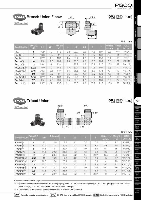
72
StandardSeries
MiniSeries
StainlessSeries
ChemicalSeries
PPSeries
EGSeries
Anti-spatter& Brass Series
Die TemperatureControl
MinimalSeries
Stop FittingSeries
RotarySeries
Twist-ProofFitting
Block andConnector
Coupling
ColorCap
FITTING
TUBE
VALVE
CONTROLLERMAKE-TO-ORDERPRODUCTS
http://en.pisco.co.jp
Page for special specificationsOP.P.000 3D CAD data is available at PISCO website.CAD
3D CAD CAD data is available at PISCO website.
ød
2-F3-øD
3-øP
3-C 3-E
T
Tripod UnionPVU OP.P.754 CADCAD
3D
compliant
Unit:mm
Model codeTube O.D.
øD øPTube end
CE ød F T
Orifice bore(ømm)
Weight(g)
CADファイル名
PVU4④ 4 10 14.9 17.8 3.2 6.5 10.4 3 7.2 PVU4_PVU6④ 6 12.5 17 20.5 4.2 8 13.5 4.6 10 PVU6_PVU8④ 8 14.5 18.1 22.7 4.2 10 15.6 6.7 15 PVU8_PVU10④ 10 17.5 20.2 26.2 4.2 12 18.2 8.3 25 PVU10_PVU12④ 12 21 23.4 30.2 4.2 14 21.7 10.3 35 PVU12_PVU5/32④ 5/32 10 14.9 17.8 3.2 6.5 10.4 3 7.2 PVU5_32_PVU3/16④ 3/16 12.5 17.4 20.9 4.2 8 13.5 4 10 PVU3_16_PVU1/4④ 1/4 12.5 17 20.5 4.2 8 13.5 5.3 11 PVU1_4_PVU5/16④ 5/16 14.5 18.1 22.7 4.2 10 15.6 6.7 15 PVU5_16_PVU3/8④ 3/8 17.5 20.2 26.2 4.2 12 18.2 8.2 25 PVU3_8_PVU1/2④ 1/2 21 23.7 30.5 4.2 14 21.7 11 34 PVU1_2_
Common caution in this page
※1. ④ in Model code / Replaced with "W" for Light-gray color, "-C" for Clean-room package, "W-C" for Light-gray color and Clean-
room packge, "-UC" for Clean-wash and Clean-room package
※2. Orifice bore is the smallest passage converted in terms of the diameter.
Unit:mm
Model codeTube O.D.
øD E1 øPTube end
CJ E2 ød F T
Orifice bore(ømm)
Weight(g)
CADfile name
PAU4④ 4 16.9 10 14.9 10.3 22.7 3.2 14.2 10.4 3.5 7.7 PAU4_PAU6④ 6 19.8 12.5 17 12.5 26.2 4.2 15.5 13.5 4.5 11 PAU6_PAU8④ 8 22.7 14.5 18.1 14.5 29.4 4.2 16.9 15.6 6.4 16 PAU8_PAU10④ 10 25 17.5 20.2 17.5 33.5 4.2 18.5 18.2 8.5 27 PAU10PAU12④ 12 29.4 21 23.4 21 35.2 4.2 20.4 21.7 10.4 39 PAU12_PAU5/32④ 5/32 16.9 10 14.9 10.3 22.7 3.2 14.2 10.4 3.5 7.7 PAU5_32_PAU3/16④ 3/16 20.2 12.5 17.4 12.5 26.6 4.2 15.9 13.5 4.4 12 PAU3_16_PAU1/4④ 1/4 19.8 12.5 17 12.5 26.2 4.2 15.5 13.5 4.8 11 PAU1_4_PAU5/16④ 5/16 22.7 14.5 18.1 14.5 29.4 4.2 16.9 15.6 6.4 16 PAU5_16_PAU3/8④ 3/8 25 17.5 20.2 17.5 33.5 4.2 18.5 18.2 8.5 27 PAU3_8_PAU1/2④ 1/2 29.7 21 23.7 21 35.5 4.2 20.7 21.7 10.4 38 PAU1_2_
3-øD
ød
3-øP
3-C
E2
E1
T
F
JBranch Union ElbowPAU OP.P.754 CADCAD
3D
compliant
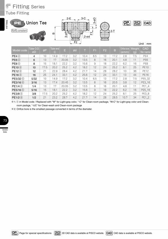
Fitting SeriesTube Fitting
StandardSeries
73
FITTING
Page for special specificationsOP.P.000 3D CAD data is available at PISCO website.CAD
3D CAD CAD data is available at PISCO website.
Unit:mm
Model codeTube O.D.
øD øPTube end
CE ød T F1 F2 B
Orifice bore(ømm)
Weight(g)
CADfile name
PE4④ 4 10 14.9 17.2 3.2 10.4 6.5 13 17.2 2.8 7.5 PE4PE6④ 6 13 17 20.05 3.2 13.5 8 16 20.1 4.8 11 PE6PE8④ 8 15 18.1 22.2 3.2 15.6 9 18 22.2 6.2 16 PE8PE10④ 10 17.5 20.2 25.2 4.2 18.2 12 24 25.2 8.1 25 PE10PE12④ 12 21 22.9 28.4 4.2 21.7 14 28 28.2 10 36 PE12PE16④ 16 25 24.1 33.1 4.2 25.6 12 24 33.1 13 44 PE16PE5/32④ 5/32 10 14.9 17.2 3.2 10.4 6.5 13 17.2 2.8 7.5 PE5_32PE3/16④ 3/16 13 17.4 20.45 3.2 13.5 8 16 20.5 3.8 12 PE3_16PE1/4④ 1/4 13 17 20.05 3.2 13.5 8 16 20.1 4.8 11 PE1_4PE5/16④ 5/16 15 18.1 22.2 3.2 15.6 9 18 22.2 6.2 16 PE5_16PE3/8④ 3/8 17.5 20.2 25.2 4.2 18.2 12 24 25.2 8.1 25 PE3_8PE1/2④ 1/2 21 23.2 28.7 4.2 21.7 14 28 28.5 10.7 34 PE1_2
※1. ④ in Model code / Replaced with "W" for Light-gray color, "-C" for Clean-room package, "W-C" for Light-gray color and Clean-
room packge, "-UC" for Clean-wash and Clean-room package
※2. Orifice bore is the smallest passage converted in terms of the diameter.
3-ø
D
3-ø
P
3-C2-E
2-ød
F1B
2-T
F2
Union TeePE OP.P.754 CADCAD
3D
compliant
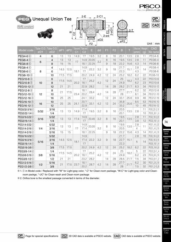
74
StandardSeries
MiniSeries
StainlessSeries
ChemicalSeries
PPSeries
EGSeries
Anti-spatter& Brass Series
Die TemperatureControl
MinimalSeries
Stop FittingSeries
RotarySeries
Twist-ProofFitting
Block andConnector
Coupling
ColorCap
FITTING
TUBE
VALVE
CONTROLLERMAKE-TO-ORDERPRODUCTS
http://en.pisco.co.jp
Page for special specificationsOP.P.000 3D CAD data is available at PISCO website.CAD
3D CAD CAD data is available at PISCO website.
Unit:mm
Model codeTube O.D.
øD1Tube O.D.
øD2 øP1 øP2Tube endC1
Tube endC2
E ød F1 F2 B TOrifice bore(ømm)
Weight(g)
CADfile name
PEG4-6④ 4 6 13 13 14.9 17 19.5 3.2 8 16 20.1 13.5 2.8 11 PEG4-6PEG6-4④
64 13 13
1714.9 20.05
3.28 16 19.5 13.5 2.8 11 PEG6-4
PEG6-8④ 8 15 15 18.1 22.25 9 18 22.2 15.6 4.3 14 PEG6-8PEG8-4④
84
14.5 12.518.1
14.922.2 3.2 9 18
21.715.1
2.814
PEG8-4PEG8-6④ 6 17 22.3 4.3 PEG8-6PEG8-10④ 10 17.5 17.5 20.2 24.9 4.2 12 24 25.2 18.2 6.2 22 PEG8-10PEG10-6④
106
17.5 14.520.2
1725.2
4.212 24
2518.2
4.3 22 PEG10-6PEG10-8④ 8 18.1 24.9 6.2 23 PEG10-8PEG10-12④ 12 21 21 22.9 28.2 14 28 28.2 21.7 8.3 34 PEG10-12PEG12-8④
128
21 17.523.4
18.128.4
4.214 28
27.721.7
6.2 32 PEG12-8PEG12-10④ 10 20.2 28 8.1 34 PEG12-10PEG12-16④ 16 25 25 24.1 33.2 12 24 33.1 25.6 9.9 46 PEG12-16PEG16-10④
1610
25 25 24.120.7
33.1 4.2 12 2435.8
25.68.5 53 PEG16-10
PEG16-12④ 12 22.9 33.2 10 45 PEG16-12PEG5/32-3/16④
5/323/16
13 13 14.917.4
19.5 3.2 8 1620.5
13.5 2.811 PEG5_32-3_16
PEG5/32-1/4④ 1/4 17 20.1 10 PEG5_32-1_4PEG3/16-5/32④
3/165/32
13 13 17.414.9
20.45 3.2 8 1619.5
13.52.8 11 PEG3_16-5_32
PEG3/16-1/4④ 1/4 17 20.1 3.8 12 PEG3_16-1_4PEG1/4-5/32④
1/45/32
13 1317
14.920.05
3.28 16
19.513.5
2.811
PEG1_4-5_32PEG1/4-3/16④ 3/16 17.4 20.5 4 PEG1_4-3_16PEG1/4-5/16④ 5/16 15 15 18.1 22.25 9 18 22.2 15.6 4.3 14 PEG1_4-5_16PEG5/16-5/32④
5/16
5/3214.5 12.5
18.1
14.922.2 3.2 9 18
21.715.1
2.8 16 PEG5_16-5_32PEG5/16-3/16④ 3/16 17.4 22.7
5 14PEG5_16-3_16
PEG5/16-1/4④ 1/4 17 22.3 PEG5_16-1_4PEG5/16-3/8④ 3/8 17.5 17.5 20.2 24.9 4.2 12 24 25.2 18.2 6.2 22 PEG5_16-3_8PEG3/8-1/4④
3/81/4
17.5 14.520.2
1725.2
4.212 24
2518.2
5 22 PEG3_8-1_4PEG3/8-5/16④ 5/16 18.1 24.9 6.2 23 PEG3_8-5_16PEG3/8-1/2④ 1/2 21 21 23.2 28.2 14 28 28.5 21.7 7.5 34 PEG3_8-1_2PEG1/2-5/16④
1/25/16
21 17.5 23.718.1
28.7 4.2 14 2827.7
21.76.2 30 PEG1_2-5_16
PEG1/2-3/8④ 3/8 20.2 28 7.5 32 PEG1_2-3_8
※1. ④ in Model code / Replaced with "W" for Light-gray color, "-C" for Clean-room package, "W-C" for Light-gray color and Clean-
room packge, "-UC" for Clean-wash and Clean-room package
※2. Orifice bore is the smallest passage converted in terms of the diameter.
2-ø
D1
2-ø
P1
øP2
2-C12-E
2-ød
F2
2-T
øD2
C2B F1
Unequal Union TeePEG
compliant
OP.P.754
CADCAD3D
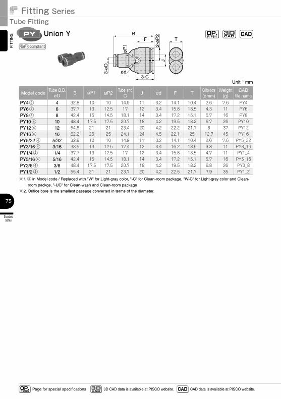
Fitting SeriesTube Fitting
StandardSeries
75
FITTING
Page for special specificationsOP.P.000 3D CAD data is available at PISCO website.CAD
3D CAD CAD data is available at PISCO website.
Unit:mm
Model codeTube O.D.
øD B øP1 øP2Tube end
CJ ød F T
Orifice bore(ømm)
Weight(g)
CADfile name
PY4④ 4 32.8 10 10 14.9 11 3.2 14.1 10.4 2.6 7.6 PY4PY6④ 6 37.7 13 12.5 17 12 3.4 15.8 13.5 4.3 11 PY6PY8④ 8 42.4 15 14.5 18.1 14 3.4 17.2 15.1 5.7 16 PY8PY10④ 10 48.4 17.5 17.5 20.7 18 4.2 19.5 18.2 6.7 26 PY10PY12④ 12 54.8 21 21 23.4 20 4.2 22.2 21.7 8 37 PY12PY16④ 16 62.2 25 25 24.1 24 4.5 22.1 25 12.7 45 PY16PY5/32④ 5/32 32.8 10 10 14.9 11 3.2 14.1 10.4 2.6 7.6 PY5_32PY3/16④ 3/16 38.5 13 12.5 17.4 12 3.4 16.2 13.5 3.8 11 PY3_16PY1/4④ 1/4 37.7 13 12.5 17 12 3.4 15.8 13.5 4.7 11 PY1_4PY5/16④ 5/16 42.4 15 14.5 18.1 14 3.4 17.2 15.1 5.7 16 PY5_16PY3/8④ 3/8 48.4 17.5 17.5 20.7 18 4.2 19.5 18.2 6.8 26 PY3_8PY1/2④ 1/2 55.4 21 21 23.7 20 4.2 22.5 21.7 7.9 35 PY1_2
※1. ④ in Model code / Replaced with "W" for Light-gray color, "-C" for Clean-room package, "W-C" for Light-gray color and Clean-
room packge, "-UC" for Clean-wash and Clean-room package
※2. Orifice bore is the smallest passage converted in terms of the diameter.
3-ø
D
ød
øP
1
3-C
FB
J2-
øP
2
TUnion YPY OP.
P.754 CADCAD3D
compliant
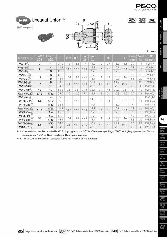
76
StandardSeries
MiniSeries
StainlessSeries
ChemicalSeries
PPSeries
EGSeries
Anti-spatter& Brass Series
Die TemperatureControl
MinimalSeries
Stop FittingSeries
RotarySeries
Twist-ProofFitting
Block andConnector
Coupling
ColorCap
FITTING
TUBE
VALVE
CONTROLLERMAKE-TO-ORDERPRODUCTS
http://en.pisco.co.jp
Page for special specificationsOP.P.000 3D CAD data is available at PISCO website.CAD
3D CAD CAD data is available at PISCO website.
Unit:mm
Model codeTube O.D.
øD1Tube O.D.
øD2 B øP1 øP2Tube endC1
Tube endC2
J ød F TOrifice bore(ømm)
Weight(g)
CADfile name
PW6-4④ 6 4 37.2 13 12.5 17 14.9 12 3.4 15.2 13.5 3.7 11 PW6-4PW8-4④
84 41.9
14.5 12.5 18.114.9
14 3.416.7
15.13.9
13PW8-4
PW8-6④ 6 42.5 17 17.3 5 PW8-6PW10-6④
106 48.2
17.5 14.5 20.217
18 4.519.3
18.25.7 19 PW10-6
PW10-8④ 8 48.1 18.1 19.2 6.5 20 PW10-8PW12-8④
128 54.3
21 17.5 23.418.1
20 4.521.7
21.77.5 27 PW12-8
PW12-10④ 10 54.6 20.2 22 7.8 30 PW12-10PW16-12④ 16 12 62.3 25 25 24.1 23.4 24 4.5 22.2 25 9 48 PW16-12PW3/16-5/32④ 3/16 5/32 37.6 13 12.5 17.4 14.9 12 3.4 15.2 13.5 3.7 11 PW3_16-5_32PW1/4-4④
1/44 37.2
13 12.5 1714.9
12 3.415.2
13.53.7
11PW1_4-4
PW1/4-5/32④ 5/32 37.2 PW1_4-5_32PW1/4-3/16④ 3/16 38.1 17.4 16.2 4 PW1_4-3_16PW5/16-5/32④
5/165/32 41.9
14.5 12.5 18.114.9
14 3.416.7
15.13.9
13PW5_16-5_32
PW5/16-1/4④ 1/4 42.5 17 17.3 5 PW5_16-1_4PW3/8-1/4④
3/81/4 48.2
17.5 14.5 20.217
18 4.519.3
18.25.7 19 PW3_8-1_4
PW3/8-5/16④ 5/16 48.1 18.1 19.2 6.5 20 PW3_8-5_16PW1/2-5/16④
1/25/16 54.6
21 17.5 23.718.1
20 4.521.7
21.77.5 27 PW1_2-5_16
PW1/2-3/8④ 3/8 54.9 20.2 22 7.8 30 PW1_2-3_8
※1. ④ in Model code / Replaced with "W" for Light-gray color, "-C" for Clean-room package, "W-C" for Light-gray color and Clean-
room packge, "-UC" for Clean-wash and Clean-room package
※2. Orifice bore is the smallest passage converted in terms of the diameter.
øD
1
ød
øP
1
C1 2-C2
F
B
J
T
2-ø
D2
2-ø
P2Unequal Union YPW OP.
P.754 CADCAD3D
compliant
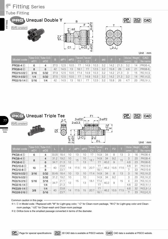
Fitting SeriesTube Fitting
StandardSeries
77
FITTING
Page for special specificationsOP.P.000 3D CAD data is available at PISCO website.CAD
3D CAD CAD data is available at PISCO website.
Unit:mm
Model codeTube O.D.
øD1Tube O.D.
øD2 L E J øP1 øP2Tube endC1
Tube endC2
F1 F2 TOrifice bore(ømm)
Weight(g)
CADfile name
PKG6-4④ 6 4 30.05 18.4 10 13 10 17 14.9 34 8 13 3 16 PKG6-4PKG8-4④
84 31.2 19.2 10
1510
18.114.9 34 9.2
153 20 PKG8-4
PKG8-6④ 6 34.7 21.3 12 13 17 40.2 9 4.6 23 PKG8-6PKG10-6④
106
4023.8
14 17.5 15 20.717
46.2 10.5 17.54.6 31 PKG10-6
PKG10-8④ 8 23.7 18.1 7 33 PKG10-8PKG3/16-5/32④ 3/16 5/32 30.45 18.4 10 13 10 17.4 14.9 34 8 13 3 16 PKG3_16-5_32PKG5/16-5/32④
5/165/32 31.2 19.2 10
1510
18.114.9 34 9.2
153 20 PKG5_16-5_32
PKG5/16-3/16④ 3/1634.7
21.712 13
17.440.2 9
4 23 PKG5_16-3_16PKG5/16-1/4④ 1/4 21.3 17 4.6 22 PKG5_16-1_4PKG3/8-1/4④
3/81/4
4023.8
14 17.5 15 20.717
46.2 10.5 17.54.6 32 PKG3_8-1_4
PKG3/8-5/16④ 5/16 23.7 18.1 7 33 PKG3_8-5_16
Common caution in this page
※1. ④ in Model code / Replaced with "W" for Light-gray color, "-C" for Clean-room package, "W-C" for Light-gray color and Clean-
room packge, "-UC" for Clean-wash and Clean-room package
※2. Orifice bore is the smallest passage converted in terms of the diameter.
2-ø3.3
F1
2-L
F2
2-ø
D1
2-ø
P1
3-øP23-øD2
3-C
2
2-T
2-C1 2-J
E
Unequal Triple TeePKG OP.P.754 CADCAD
3D
compliant
øD
1
ød
C1
FB
4-ø
D2
4-ø
P2
4-C2
øP
1
2-J
T
Unequal Double YPRG OP.P.754 CADCAD
3D
compliant
Unit:mm
Model codeTube O.D.
øD1Tube O.D.
øD2 B øP1 øP2Tube endC1
Tube endC2
J ød F TOrifice bore(ømm)
Weight(g)
CADfile name
PRG6-4④ 6 4 37.5 12.5 10.5 17 14.9 10.3 3.2 14.2 21.3 3.2 14 PRG6-4_PRG8-6④ 8 6 42 14.5 13 18.1 17 12.5 3.2 15.8 26 4.6 21 PRG8-6_PRG3/16-5/32④ 3/16 5/32 37.9 12.5 10.5 17.4 14.9 10.3 3.2 14.2 21.3 3 15 PRG3_16-5_32_PRG1/4-5/32④ 1/4 5/32 37.5 12.5 10.5 17 14.9 10.3 3.2 14.2 21.3 3.2 14 PRG1_4-5_32_PRG5/16-1/4④ 5/16 1/4 42 14.5 13 18.1 17 12.5 3.2 15.8 26 4.7 20 PRG5_16-1_4_
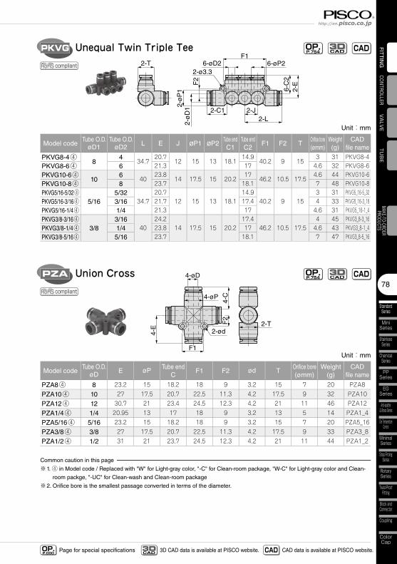
78
StandardSeries
MiniSeries
StainlessSeries
ChemicalSeries
PPSeries
EGSeries
Anti-spatter& Brass Series
Die TemperatureControl
MinimalSeries
Stop FittingSeries
RotarySeries
Twist-ProofFitting
Block andConnector
Coupling
ColorCap
FITTING
TUBE
VALVE
CONTROLLERMAKE-TO-ORDERPRODUCTS
http://en.pisco.co.jp
Page for special specificationsOP.P.000 3D CAD data is available at PISCO website.CAD
3D CAD CAD data is available at PISCO website.
2-ød
4-øP
4-C
F2
4-E
F1
2-T
4-øDUnion CrossPZA OP.P.754 CADCAD
3D
compliant
Unit:mm
Model codeTube O.D.
øD E øP Tube endC
F1 F2 ød TOrifice bore(ømm)
Weight(g)
CADfile name
PZA8④ 8 23.2 15 18.2 18 9 3.2 15 7 20 PZA8
PZA10④ 10 27 17.5 20.7 22.5 11.3 4.2 17.5 9 32 PZA10
PZA12④ 12 30.7 21 23.4 24.5 12.3 4.2 21 11 46 PZA12
PZA1/4④ 1/4 20.95 13 17 18 9 3.2 13 5 14 PZA1_4
PZA5/16④ 5/16 23.2 15 18.2 18 9 3.2 15 7 20 PZA5_16
PZA3/8④ 3/8 27 17.5 20.7 22.5 11.3 4.2 17.5 9 33 PZA3_8
PZA1/2④ 1/2 31 21 23.7 24.5 12.3 4.2 21 11 44 PZA1_2
Common caution in this page
※1. ④ in Model code / Replaced with "W" for Light-gray color, "-C" for Clean-room package, "W-C" for Light-gray color and Clean-
room packge, "-UC" for Clean-wash and Clean-room package
※2. Orifice bore is the smallest passage converted in terms of the diameter.
Unit:mm
Model codeTube O.D.
øD1Tube O.D.
øD2 L E J øP1 øP2Tube endC1
Tube endC2
F1 F2 TOrifice bore(ømm)
Weight(g)
CADfile name
PKVG8-4④8
434.7
20.712 15 13 18.1
14.940.2 9 15
3 31 PKVG8-4PKVG8-6④ 6 21.3 17 4.6 32 PKVG8-6PKVG10-6④
106
4023.8
14 17.5 15 20.217
46.2 10.5 17.54.6 44 PKVG10-6
PKVG10-8④ 8 23.7 18.1 7 48 PKVG10-8PKVG5/16-5/32④
5/165/32
34.720.7
12 15 13 18.114.9
40.2 9 153 31 PKVG5_16-5_32
PKVG5/16-3/16④ 3/16 21.7 17.4 4 33 PKVG5_16-3_16PKVG5/16-1/4④ 1/4 21.3 17 4.6 31 PKVG5_16-1_4PKVG3/8-3/16④
3/83/16
4024.2
14 17.5 15 20.217.4
46.2 10.5 17.54 45 PKVG3_8-3_16
PKVG3/8-1/4④ 1/4 23.8 17 4.6 43 PKVG3_8-1_4PKVG3/8-5/16④ 5/16 23.7 18.1 7 47 PKVG3_8-5_16
2-ø3.3
F1
2-L
F2
2-ø
D12-
øP
1
6-øD2 6-øP2
6-C
2
2-C1 2-J
2-E
2-T
Unequal Twin Triple TeePKVG OP.P.754 CADCAD
3D
compliant
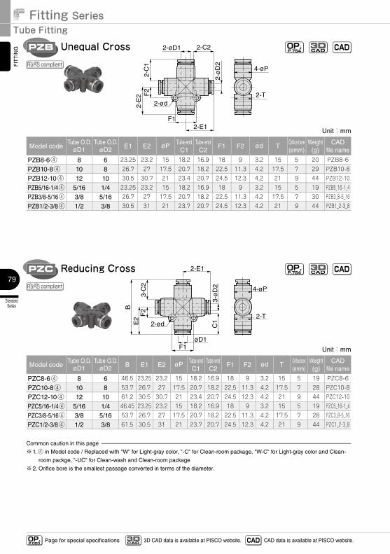
Fitting SeriesTube Fitting
StandardSeries
79
FITTING
Page for special specificationsOP.P.000 3D CAD data is available at PISCO website.CAD
3D CAD CAD data is available at PISCO website.
2-øD1
2-ød
4-øP
2-T
2-C2
2-C
1F
2
2-E1F1
2-E
2
2-ø
D2
Unequal CrossPZB OP.P.754 CADCAD
3D
compliant
Unit:mm
Model codeTube O.D.
øD1Tube O.D.
øD2 E1 E2 øP Tube endC1
Tube endC2
F1 F2 ød TOrifice bore(ømm)
Weight(g)
CADfile name
PZB8-6④ 8 6 23.25 23.2 15 18.2 16.9 18 9 3.2 15 5 20 PZB8-6
PZB10-8④ 10 8 26.7 27 17.5 20.7 18.2 22.5 11.3 4.2 17.5 7 29 PZB10-8
PZB12-10④ 12 10 30.5 30.7 21 23.4 20.7 24.5 12.3 4.2 21 9 44 PZB12-10
PZB5/16-1/4④ 5/16 1/4 23.25 23.2 15 18.2 16.9 18 9 3.2 15 5 19 PZB5_16-1_4
PZB3/8-5/16④ 3/8 5/16 26.7 27 17.5 20.7 18.2 22.5 11.3 4.2 17.5 7 30 PZB3_8-5_16
PZB1/2-3/8④ 1/2 3/8 30.5 31 21 23.7 20.7 24.5 12.3 4.2 21 9 44 PZB1_2-3_8
Unit:mm
Model codeTube O.D.
øD1Tube O.D.
øD2 B E1 E2 øP Tube endC1
Tube endC2
F1 F2 ød TOrifice bore(ømm)
Weight(g)
CADfile name
PZC8-6④ 8 6 46.5 23.25 23.2 15 18.2 16.9 18 9 3.2 15 5 19 PZC8-6
PZC10-8④ 10 8 53.7 26.7 27 17.5 20.7 18.2 22.5 11.3 4.2 17.5 7 28 PZC10-8
PZC12-10④ 12 10 61.2 30.5 30.7 21 23.4 20.7 24.5 12.3 4.2 21 9 44 PZC12-10
PZC5/16-1/4④ 5/16 1/4 46.45 23.25 23.2 15 18.2 16.9 18 9 3.2 15 5 19 PZC5_16-1_4
PZC3/8-5/16④ 3/8 5/16 53.7 26.7 27 17.5 20.7 18.2 22.5 11.3 4.2 17.5 7 28 PZC3_8-5_16
PZC1/2-3/8④ 1/2 3/8 61.5 30.5 31 21 23.7 20.7 24.5 12.3 4.2 21 9 44 PZC1_2-3_8
Common caution in this page
※1. ④ in Model code / Replaced with "W" for Light-gray color, "-C" for Clean-room package, "W-C" for Light-gray color and Clean-
room packge, "-UC" for Clean-wash and Clean-room package
※2. Orifice bore is the smallest passage converted in terms of the diameter.
øD1
2-ød
4-øP
2-T
3-C
2
C1
F2
2-E1
F1
E2
B
3-ø
D2
Reducing CrossPZC OP.P.754 CADCAD
3D
compliant
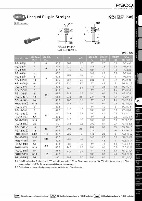
80
StandardSeries
MiniSeries
StainlessSeries
ChemicalSeries
PPSeries
EGSeries
Anti-spatter& Brass Series
Die TemperatureControl
MinimalSeries
Stop FittingSeries
RotarySeries
Twist-ProofFitting
Block andConnector
Coupling
ColorCap
FITTING
TUBE
VALVE
CONTROLLERMAKE-TO-ORDERPRODUCTS
http://en.pisco.co.jp
Page for special specificationsOP.P.000 3D CAD data is available at PISCO website.CAD
3D CAD CAD data is available at PISCO website.
CB
øD1
øD2
øP
E
CB
øD1
øD2
øP
E
PGJ4-6, PGJ6-8PGJ8-10, PGJ10-12
Unequal Plug-in StraightPGJ
compliant
OP.P.754 CADCAD
3D
Unit:mm
Model codeTube O.D.
øD1Tube dia.
øD2 B E øP Tube endC
Orifice bore(ømm)
Weight(g)
CADfile name
PGJ4-6④ 6 4 38.8 18.9 12.5 17 2.5 3.5 PGJ4-6
PGJ6-4④ 46
37.7 22.3 10 14.9 2.8 2.9 PGJ6-4
PGJ6-8④ 8 43.2 21.9 14.5 18.1 4 5.3 PGJ6-8
PGJ8-4④ 4
8
40.223.3 12.5
14.9 2.8 3.8 PGJ8-4
PGJ8-6④ 6 40.8 17 4.3 4 PGJ8-6
PGJ8-10④ 10 46.5 22.9 17.5 20.2 6 8.7 PGJ8-10
PGJ8-1/4④ 1/4 40.8 23.3 12.5 17 4.8 4 PGJ8-1_4
PGJ10-4④ 4
10
42.228.3 12.5
14.9 2.8 4.3 PGJ10-4
PGJ10-6④ 6 43.8 17 4.3 4.5 PGJ10-6
PGJ10-8④ 8 43.7 24.8 14.5 18.1 6.1 5.8 PGJ10-8
PGJ10-12④ 12 51.2 23.5 21 23.4 7.5 13 PGJ10-12
PGJ10-1/4④ 1/4 43.8 28.3 12.5 17 4.8 4.5 PGJ10-1_4
PGJ10-5/16④ 5/16 43.7 24.8 14.5 18.1 6.1 5.8 PGJ10-5_16
PGJ12-6④ 6
12
48.833.5 14.5
17 4.3 6 PGJ12-6
PGJ12-8④ 8 49.7 18.1 6.1 6.7 PGJ12-8
PGJ12-10④ 10 50 28.8 17.5 20.2 8.1 9.6 PGJ12-10
PGJ12-1/4④ 1/4 48.833.5 14.5
17 4.8 5.9 PGJ12-1_4
PGJ12-5/16④ 5/16 49.7 18.1 6.1 6.7 PGJ12-5_16
PGJ12-3/8④ 3/8 50 28.8 17.5 20.2 8.1 9.7 PGJ12-3_8
PGJ16-10④ 1016
55.230.8 21
20.2 8.1 15 PGJ16-10
PGJ16-12④ 12 55.4 23.4 10 16 PGJ16-12
PGJ1/4-5/32④ 5/32 1/4 37.7 22.3 10 14.9 2.8 3 PGJ1_4-5_32
PGJ5/16-5/32④ 5/325/16
40.223.3 12.5
14.9 2.8 3.8 PGJ5_16-5_32
PGJ5/16-1/4④ 1/4 40.8 17 4.8 4 PGJ5_16-1_4
PGJ3/8-1/4④ 1/43/8
43.8 28.3 12.5 17 4.8 4.3 PGJ3_8-1_4
PGJ3/8-5/16④ 5/16 43.7 24.8 14.5 18.1 6.1 5.6 PGJ3_8-5_16
PGJ1/2-1/4④ 1/41/2
48.833.5 14.5
17 4.8 6.5 PGJ1_2-1_4
PGJ1/2-5/16④ 5/16 49.7 18.1 6.1 7.3 PGJ1_2-5_16
PGJ1/2-3/8④ 3/8 50 28.8 17.5 20.2 8.1 11 PGJ1_2-3_8
※1. ④ in Model code / Replaced with "W" for Light-gray color, "-C" for Clean-room package, "W-C" for Light-gray color and Clean-
room packge, "-UC" for Clean-wash and Clean-room package
※2. Orifice bore is the smallest passage converted in terms of the diameter.
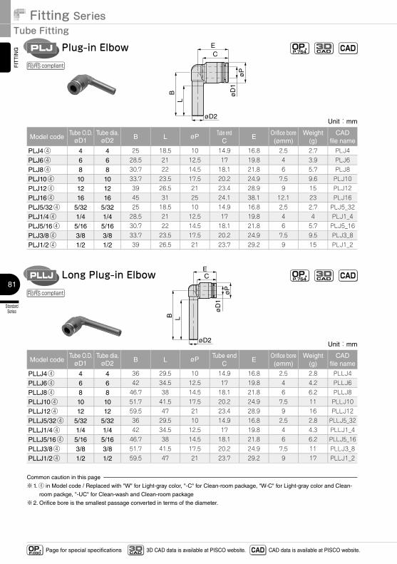
Fitting SeriesTube Fitting
StandardSeries
81
FITTING
Page for special specificationsOP.P.000 3D CAD data is available at PISCO website.CAD
3D CAD CAD data is available at PISCO website.
øD
1ø
P
C
øD2
E
BL
Plug-in ElbowPLJ
compliant
OP.P.754 CADCAD
3D
Unit:mm
Model codeTube O.D.
øD1Tube dia.
øD2 B L øP Tube endC
EOrifice bore(ømm)
Weight(g)
CADfile name
PLJ4④ 4 4 25 18.5 10 14.9 16.8 2.5 2.7 PLJ4
PLJ6④ 6 6 28.5 21 12.5 17 19.8 4 3.9 PLJ6
PLJ8④ 8 8 30.7 22 14.5 18.1 21.8 6 5.7 PLJ8
PLJ10④ 10 10 33.7 23.5 17.5 20.2 24.9 7.5 9.6 PLJ10
PLJ12④ 12 12 39 26.5 21 23.4 28.9 9 15 PLJ12
PLJ16④ 16 16 45 31 25 24.1 38.1 12.1 23 PLJ16
PLJ5/32④ 5/32 5/32 25 18.5 10 14.9 16.8 2.5 2.7 PLJ5_32
PLJ1/4④ 1/4 1/4 28.5 21 12.5 17 19.8 4 4 PLJ1_4
PLJ5/16④ 5/16 5/16 30.7 22 14.5 18.1 21.8 6 5.7 PLJ5_16
PLJ3/8④ 3/8 3/8 33.7 23.5 17.5 20.2 24.9 7.5 9.5 PLJ3_8
PLJ1/2④ 1/2 1/2 39 26.5 21 23.7 29.2 9 15 PLJ1_2
Unit:mm
Model codeTube O.D.
øD1Tube dia.
øD2 B L øP Tube endC
EOrifice bore(ømm)
Weight(g)
CADfile name
PLLJ4④ 4 4 36 29.5 10 14.9 16.8 2.5 2.8 PLLJ4
PLLJ6④ 6 6 42 34.5 12.5 17 19.8 4 4.2 PLLJ6
PLLJ8④ 8 8 46.7 38 14.5 18.1 21.8 6 6.2 PLLJ8
PLLJ10④ 10 10 51.7 41.5 17.5 20.2 24.9 7.5 11 PLLJ10
PLLJ12④ 12 12 59.5 47 21 23.4 28.9 9 16 PLLJ12
PLLJ5/32④ 5/32 5/32 36 29.5 10 14.9 16.8 2.5 2.8 PLLJ5_32
PLLJ1/4④ 1/4 1/4 42 34.5 12.5 17 19.8 4 4.3 PLLJ1_4
PLLJ5/16④ 5/16 5/16 46.7 38 14.5 18.1 21.8 6 6.2 PLLJ5_16
PLLJ3/8④ 3/8 3/8 51.7 41.5 17.5 20.2 24.9 7.5 11 PLLJ3_8
PLLJ1/2④ 1/2 1/2 59.5 47 21 23.7 29.2 9 17 PLLJ1_2
Common caution in this page
※1. ④ in Model code / Replaced with "W" for Light-gray color, "-C" for Clean-room package, "W-C" for Light-gray color and Clean-
room packge, "-UC" for Clean-wash and Clean-room package
※2. Orifice bore is the smallest passage converted in terms of the diameter.
øD
1ø
P
C
øD2
E
B L
Long Plug-in ElbowPLLJ
compliant
OP.P.754 CADCAD
3D
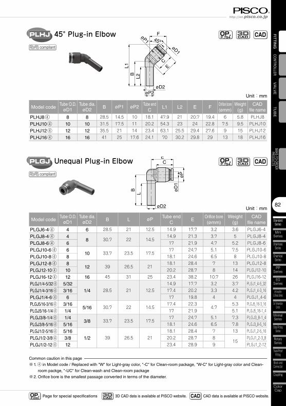
82
StandardSeries
MiniSeries
StainlessSeries
ChemicalSeries
PPSeries
EGSeries
Anti-spatter& Brass Series
Die TemperatureControl
MinimalSeries
Stop FittingSeries
RotarySeries
Twist-ProofFitting
Block andConnector
Coupling
ColorCap
FITTING
TUBE
VALVE
CONTROLLERMAKE-TO-ORDERPRODUCTS
http://en.pisco.co.jp
Page for special specificationsOP.P.000 3D CAD data is available at PISCO website.CAD
3D CAD CAD data is available at PISCO website.
øD
1ø
P
C
øD2
E
BL
Unequal Plug-in ElbowPLGJ
compliant
OP.P.754 CADCAD
3D
Unit:mm
Model codeTube O.D.
øD1Tube dia.
øD2 B L øP Tube endC
EOrifice bore(ømm)
Weight(g)
CADfile name
PLGJ6-4④ 4 6 28.5 21 12.5 14.9 17.7 3.2 3.6 PLGJ6-4
PLGJ8-4④ 48 30.7 22 14.5
14.9 21.3 3.7 5 PLGJ8-4
PLGJ8-6④ 6 17 21.9 4.7 5.2 PLGJ8-6
PLGJ10-6④ 610 33.7 23.5 17.5
17 24.7 5.1 7.5 PLGJ10-6
PLGJ10-8④ 8 18.1 24.6 6.5 8 PLGJ10-8
PLGJ12-8④ 812 39 26.5 21
18.1 28.4 7 13 PLGJ12-8
PLGJ12-10④ 10 20.2 28.7 8 14 PLGJ12-10
PLGJ16-12④ 12 16 45 31 25 23.4 38.2 10.7 26 PLGJ16-12
PLGJ1/4-5/32④ 5/321/4 28.5 21 12.5
14.9 17.7 3.2 3.7 PLGJ1_4-5_32
PLGJ1/4-3/16④ 3/16 17.4 20.2 3.3 4.2 PLGJ1_4-3_16
PLGJ1/4-6④ 6 17 19.8 4 4 PLGJ1_4-6
PLGJ5/16-3/16④ 3/165/16 30.7 22 14.5
17.4 22.34.7
5.3 PLGJ5_16-3_16
PLGJ5/16-1/4④ 1/4 17 21.9 5.1 PLGJ5_16-1_4
PLGJ3/8-1/4④ 1/43/8 33.7 23.5 17.5
17 24.7 5.1 7.3 PLGJ3_8-1_4
PLGJ3/8-5/16④ 5/16 18.1 24.6 6.5 7.8 PLGJ3_8-5_16
PLGJ1/2-5/16④ 5/161/2 39 26.5 21
18.1 28.4 7 13 PLGJ1_2-5_16
PLGJ1/2-3/8④ 3/8 20.2 28.7 815
PLGJ1_2-3_8
PLGJ1/2-12④ 12 23.4 28.9 9 PLGJ1_2-12
Common caution in this page
※1. ④ in Model code / Replaced with "W" for Light-gray color, "-C" for Clean-room package, "W-C" for Light-gray color and Clean-
room packge, "-UC" for Clean-wash and Clean-room package
※2. Orifice bore is the smallest passage converted in terms of the diameter.
Unit:mm
Model codeTube O.D.
øD1Tube dia.
øD2 B øP1 øP2 Tube endC
L1 L2 E FOrifice bore(ømm)
Weight(g)
CADfile name
PLHJ8④ 8 8 28.5 14.5 10 18.1 47.9 21 20.7 19.4 6 5.8 PLHJ8
PLHJ10④ 10 10 31.5 17.5 11 20.2 54.3 23 24 22.8 7.5 9.5 PLHJ10
PLHJ12④ 12 12 35.5 21 14 23.4 63.1 25.5 29.4 27.6 9 15 PLHJ12
PLHJ16④ 16 16 41 25 17.6 24.1 70 30.2 29.8 29 13 18 PLHJ16
øD1
øP1
CE
BL1
L2
øD2øP2
F45º
45° Plug-in ElbowPLHJ
compliant
OP.P.754 CADCAD
3D
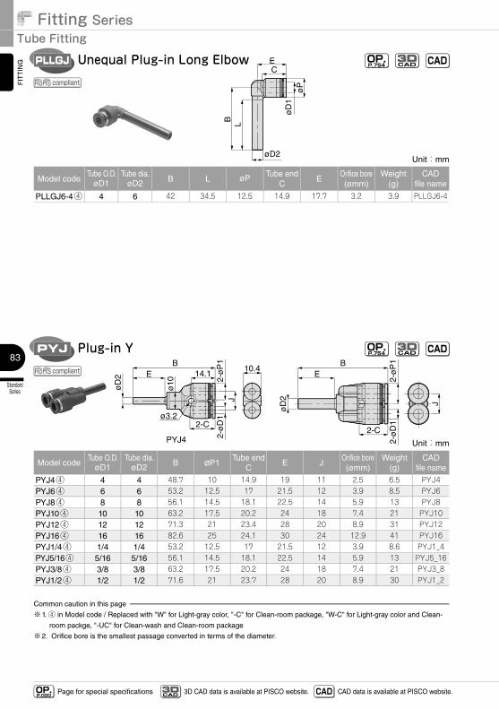
Fitting SeriesTube Fitting
StandardSeries
83
FITTING
Page for special specificationsOP.P.000 3D CAD data is available at PISCO website.CAD
3D CAD CAD data is available at PISCO website.
øD
1ø
P
C
øD2
E
B L
Unequal Plug-in Long ElbowPLLGJ
compliant
OP.P.754 CADCAD
3D
Unit:mm
Model codeTube O.D.
øD1Tube dia.
øD2 B L øP Tube endC
EOrifice bore(ømm)
Weight(g)
CADfile name
PLLGJ6-4④ 4 6 42 34.5 12.5 14.9 17.7 3.2 3.9 PLLGJ6-4
øD
2
ø10
2-C
14.1EB
J
10.4
J
BE
2-C
øD
2
2-ø
D1
2-ø
D1
2-ø
P1
2-ø
P1
ø3.2
PYJ4
Plug-in YPYJ OP.P.754 CADCAD
3D
compliant
Unit:mm
Model codeTube O.D.
øD1Tube dia.
øD2 B øP1Tube end
CE J
Orifice bore(ømm)
Weight(g)
CADfile name
PYJ4④ 4 4 48.7 10 14.9 19 11 2.5 6.5 PYJ4PYJ6④ 6 6 53.2 12.5 17 21.5 12 3.9 8.5 PYJ6PYJ8④ 8 8 56.1 14.5 18.1 22.5 14 5.9 13 PYJ8PYJ10④ 10 10 63.2 17.5 20.2 24 18 7.4 21 PYJ10PYJ12④ 12 12 71.3 21 23.4 28 20 8.9 31 PYJ12PYJ16④ 16 16 82.6 25 24.1 30 24 12.9 41 PYJ16PYJ1/4④ 1/4 1/4 53.2 12.5 17 21.5 12 3.9 8.6 PYJ1_4PYJ5/16④ 5/16 5/16 56.1 14.5 18.1 22.5 14 5.9 13 PYJ5_16PYJ3/8④ 3/8 3/8 63.2 17.5 20.2 24 18 7.4 21 PYJ3_8PYJ1/2④ 1/2 1/2 71.6 21 23.7 28 20 8.9 30 PYJ1_2
Common caution in this page
※1. ④ in Model code / Replaced with "W" for Light-gray color, "-C" for Clean-room package, "W-C" for Light-gray color and Clean-
room packge, "-UC" for Clean-wash and Clean-room package
※2. Orifice bore is the smallest passage converted in terms of the diameter.
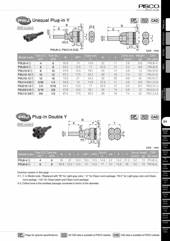
84
StandardSeries
MiniSeries
StainlessSeries
ChemicalSeries
PPSeries
EGSeries
Anti-spatter& Brass Series
Die TemperatureControl
MinimalSeries
Stop FittingSeries
RotarySeries
Twist-ProofFitting
Block andConnector
Coupling
ColorCap
FITTING
TUBE
VALVE
CONTROLLERMAKE-TO-ORDERPRODUCTS
http://en.pisco.co.jp
Page for special specificationsOP.P.000 3D CAD data is available at PISCO website.CAD
3D CAD CAD data is available at PISCO website.
øD
2
øD
2
B
J J
B
2-ø
D1
2-ø
D1
2-ø
P1
2-ø
P1
ø10
2-C2-C
14.1E10.4
E
ø3.2
PWJ6-4, PWJ1/4-5/32
Unequal Plug-in YPWJ OP.P.754 CADCAD
3D
compliant
Unit:mm
Model codeTube O.D.
øD1Tube dia.
øD2 B øP1Tube end
CE J
Orifice bore(ømm)
Weight(g)
CADfile name
PWJ6-4④ 4 6 50.9 10 14.9 22 11 2.6 6.8 PWJ6-4PWJ8-6④ 6 8 54.2 12.5 17 22.5 12 5.3 8.8 PWJ8-6PWJ10-8④ 8 10 57.6 14.5 18.1 24 14 5.9 13 PWJ10-8PWJ12-10④ 10 12 67.2 17.5 20.2 28 18 7.4 22 PWJ12-10PWJ16-12④ 12 16 73.3 21 23.4 30 20 8.9 32 PWJ16-12PWJ1/4-5/32④ 5/32 1/4 50.9 10 14.9 22.3 11 2.6 6.8 PWJ1_4-5_32PWJ5/16-1/4④ 1/4 5/16 54.2 12.5 17 22.5 12 5.3 8.7 PWJ5_16-1_4PWJ3/8-5/16④ 5/16 3/8 57.6 14.5 18.1 24 14 5.9 13 PWJ3_8-5_16PWJ1/2-3/8④ 3/8 1/2 67.2 17.5 20.2 28 18 7.4 22 PWJ1_2-3_8
ød
FEB
T
4-ø
D1
4-ø
P1
4-C
øD
2
øP
2
2-J
Plug-in Double YPRJ OP.P.754 CADCAD
3D
compliant
Unit:mm
Model codeTube O.D.
øD1Tube dia.
øD2 B E J øP1 øP2 Tube endC
ød F TOrifice bore(ømm)
Weight(g)
CADfile name
PRJ6-4④ 4 6 55 22 10.3 10.5 12.5 14.9 3.2 14.2 21.3 3.2 13 PRJ6-4_
PRJ8-6④ 6 8 60.8 23.2 12.5 13 14.5 17 3.2 15.8 26 4.6 19 PRJ8-6_
Common caution in this page
※1. ④ in Model code / Replaced with "W" for Light-gray color, "-C" for Clean-room package, "W-C" for Light-gray color and Clean-
room packge, "-UC" for Clean-wash and Clean-room package
※2. Orifice bore is the smallest passage converted in terms of the diameter.
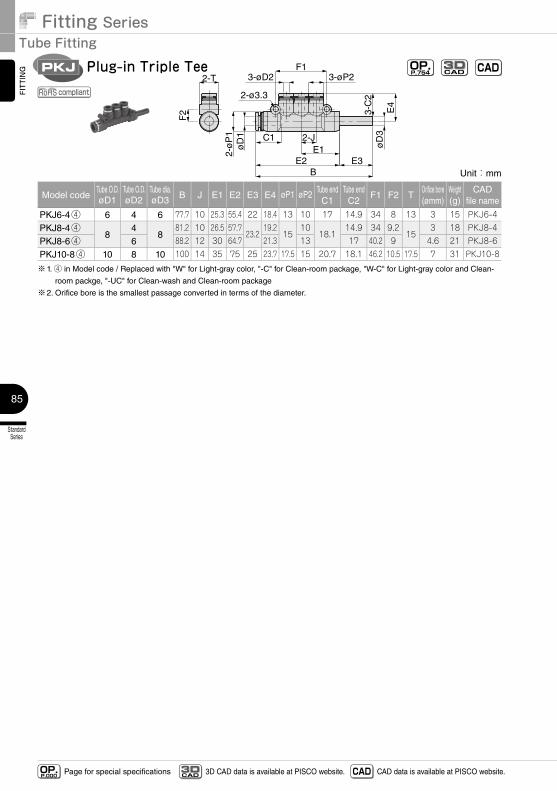
Fitting SeriesTube Fitting
StandardSeries
85
FITTING
Page for special specificationsOP.P.000 3D CAD data is available at PISCO website.CAD
3D CAD CAD data is available at PISCO website.
Unit:mm
Model codeTube O.D.øD1
Tube O.D.øD2
Tube dia.øD3 B J E1 E2 E3 E4 øP1 øP2 Tube end
C1Tube endC2
F1 F2 TOrifice bore(ømm)
Weight(g)
CADfile name
PKJ6-4④ 6 4 6 77.7 10 25.3 55.4 22 18.4 13 10 17 14.9 34 8 13 3 15 PKJ6-4
PKJ8-4④8
48
81.2 10 26.5 57.723.2
19.215
1018.1
14.9 34 9.215
3 18 PKJ8-4
PKJ8-6④ 6 88.2 12 30 64.7 21.3 13 17 40.2 9 4.6 21 PKJ8-6
PKJ10-8④ 10 8 10 100 14 35 75 25 23.7 17.5 15 20.7 18.1 46.2 10.5 17.5 7 31 PKJ10-8
※1. ④ in Model code / Replaced with "W" for Light-gray color, "-C" for Clean-room package, "W-C" for Light-gray color and Clean-
room packge, "-UC" for Clean-wash and Clean-room package
※2. Orifice bore is the smallest passage converted in terms of the diameter.
2-ø3.3
F1
BE2 E3
F2
2-T
øD
12-
øP
1
3-øP23-øD2
E1C1 2-J
3-C
2
E4
øD
3
Plug-in Triple TeePKJ OP.P.754 CADCAD
3D
compliant
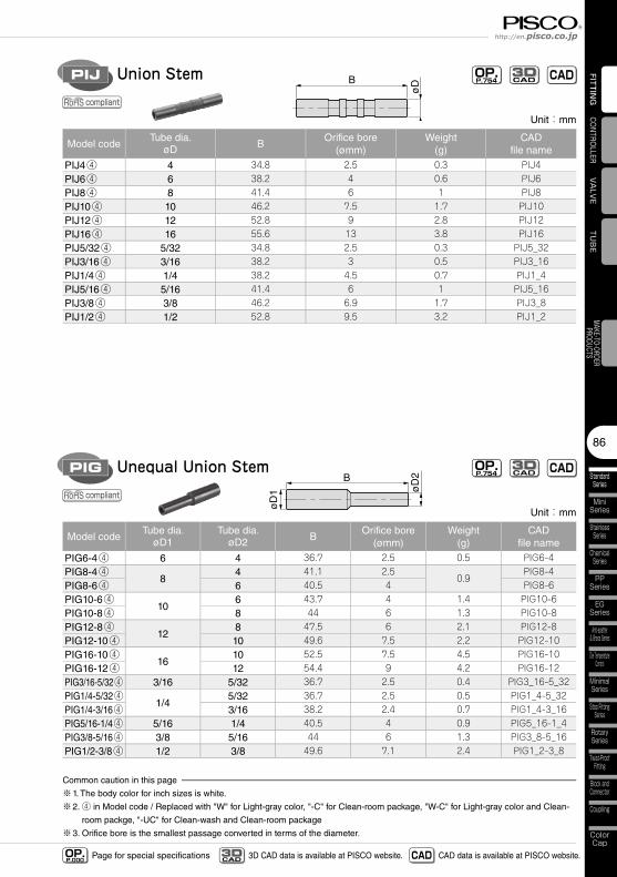
86
StandardSeries
MiniSeries
StainlessSeries
ChemicalSeries
PPSeries
EGSeries
Anti-spatter& Brass Series
Die TemperatureControl
MinimalSeries
Stop FittingSeries
RotarySeries
Twist-ProofFitting
Block andConnector
Coupling
ColorCap
FITTING
TUBE
VALVE
CONTROLLERMAKE-TO-ORDERPRODUCTS
http://en.pisco.co.jp
Page for special specificationsOP.P.000 3D CAD data is available at PISCO website.CAD
3D CAD CAD data is available at PISCO website.
B
øD
1 øD
2
Unit:mm
Model codeTube dia.
øD1Tube dia.
øD2 BOrifice bore
(ømm)Weight
(g)CAD
file name
PIG6-4④ 6 4 36.7 2.5 0.5 PIG6-4PIG8-4④
84 41.1 2.5
0.9PIG8-4
PIG8-6④ 6 40.5 4 PIG8-6PIG10-6④
106 43.7 4 1.4 PIG10-6
PIG10-8④ 8 44 6 1.3 PIG10-8PIG12-8④
128 47.5 6 2.1 PIG12-8
PIG12-10④ 10 49.6 7.5 2.2 PIG12-10PIG16-10④
1610 52.5 7.5 4.5 PIG16-10
PIG16-12④ 12 54.4 9 4.2 PIG16-12PIG3/16-5/32④ 3/16 5/32 36.7 2.5 0.4 PIG3_16-5_32PIG1/4-5/32④
1/45/32 36.7 2.5 0.5 PIG1_4-5_32
PIG1/4-3/16④ 3/16 38.2 2.4 0.7 PIG1_4-3_16PIG5/16-1/4④ 5/16 1/4 40.5 4 0.9 PIG5_16-1_4PIG3/8-5/16④ 3/8 5/16 44 6 1.3 PIG3_8-5_16PIG1/2-3/8④ 1/2 3/8 49.6 7.1 2.4 PIG1_2-3_8
Common caution in this page
※1. The body color for inch sizes is white.
※2. ④ in Model code / Replaced with "W" for Light-gray color, "-C" for Clean-room package, "W-C" for Light-gray color and Clean-
room packge, "-UC" for Clean-wash and Clean-room package
※3. Orifice bore is the smallest passage converted in terms of the diameter.
Unequal Union StemPIG
Unit:mm
Model codeTube dia.
øD BOrifice bore
(ømm)Weight
(g)CAD
file name
PIJ4④ 4 34.8 2.5 0.3 PIJ4PIJ6④ 6 38.2 4 0.6 PIJ6PIJ8④ 8 41.4 6 1 PIJ8PIJ10④ 10 46.2 7.5 1.7 PIJ10PIJ12④ 12 52.8 9 2.8 PIJ12PIJ16④ 16 55.6 13 3.8 PIJ16PIJ5/32④ 5/32 34.8 2.5 0.3 PIJ5_32PIJ3/16④ 3/16 38.2 3 0.5 PIJ3_16PIJ1/4④ 1/4 38.2 4.5 0.7 PIJ1_4PIJ5/16④ 5/16 41.4 6 1 PIJ5_16PIJ3/8④ 3/8 46.2 6.9 1.7 PIJ3_8PIJ1/2④ 1/2 52.8 9.5 3.2 PIJ1_2
B
øD
Union StemPIJ OP.P.754 CADCAD
3D
OP.P.754 CADCAD
3D
compliant
compliant
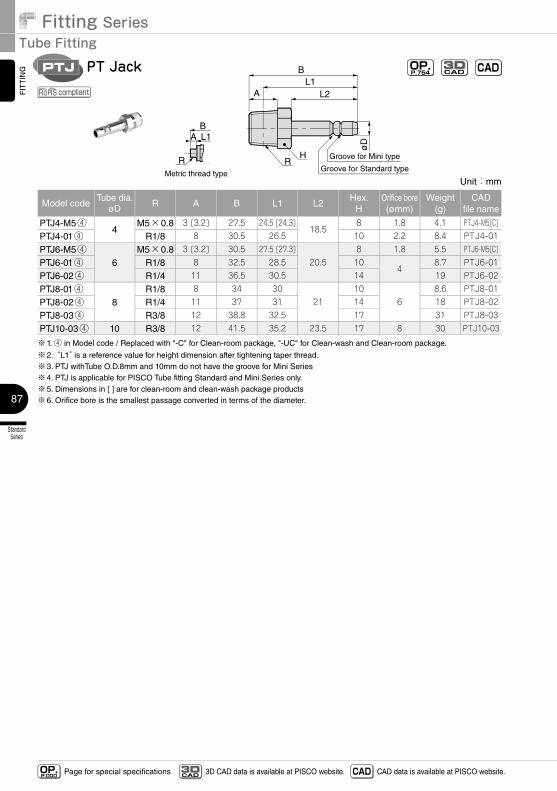
Fitting SeriesTube Fitting
StandardSeries
87
FITTING
Page for special specificationsOP.P.000 3D CAD data is available at PISCO website.CAD
3D CAD CAD data is available at PISCO website.
B
AL1
L2
RR H
øD
Metric thread type
BA L1
Groove for Mini type
Groove for Standard type
Unit:mm
Model codeTube dia.
øD R A B L1 L2Hex.
HOrifice bore(ømm)
Weight(g)
CADfile name
PTJ4-M5④4
M5×0.8 3 [3.2] 27.5 24.5 [24.3]18.5
8 1.8 4.1 PTJ4-M5[C]
PTJ4-01④ R1/8 8 30.5 26.5 10 2.2 8.4 PTJ4-01
PTJ6-M5④6
M5×0.8 3 [3.2] 30.5 27.5 [27.3]20.5
8 1.8 5.5 PTJ6-M5[C]
PTJ6-01④ R1/8 8 32.5 28.5 104
8.7 PTJ6-01
PTJ6-02④ R1/4 11 36.5 30.5 14 19 PTJ6-02
PTJ8-01④8
R1/8 8 34 3021
106
8.6 PTJ8-01
PTJ8-02④ R1/4 11 37 31 14 18 PTJ8-02
PTJ8-03④ R3/8 12 38.8 32.5 17 31 PTJ8-03
PTJ10-03④ 10 R3/8 12 41.5 35.2 23.5 17 8 30 PTJ10-03
※1. ④ in Model code / Replaced with "-C" for Clean-room package, "-UC" for Clean-wash and Clean-room package.
※2. “L1” is a reference value for height dimension after tightening taper thread.※3. PTJ withTube O.D.8mm and 10mm do not have the groove for Mini Series※4. PTJ is applicable for PISCO Tube fitting Standard and Mini Series only.※5. Dimensions in [ ] are for clean-room and clean-wash package products※6. Orifice bore is the smallest passage converted in terms of the diameter.
PT JackPTJ OP.P.754 CADCAD
3D
compliant
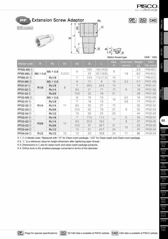
88
StandardSeries
MiniSeries
StainlessSeries
ChemicalSeries
PPSeries
EGSeries
Anti-spatter& Brass Series
Die TemperatureControl
MinimalSeries
Stop FittingSeries
RotarySeries
Twist-ProofFitting
Block andConnector
Coupling
ColorCap
FITTING
TUBE
VALVE
CONTROLLERMAKE-TO-ORDERPRODUCTS
http://en.pisco.co.jp
Page for special specificationsOP.P.000 3D CAD data is available at PISCO website.CAD
3D CAD CAD data is available at PISCO website.
B
A1
A2
L
R
R
H
Rc
Metric thread type
BA1
L
Extension Screw AdaptorPF OP.P.754 CADCAD
3D
compliant
Unit:mm
Model code R Rc A1 A2 B LHex.
HOrifice bore(ømm)
Weight(g)
CADfile name
PFM5-M5④M5×0.8
M5×0.83 [3.2]
519.5 16.5 [16.3]
81.8
5.3 PFM5-M5[C]
PFM5-M5L④ 23 20 [19.8] 6.2 PFM5-M5L[C]
PFM5-01④ Rc1/8 7 14.5 11.5 [11.3] 14 11 PFM5-01[C]
PF01-M5④
R1/8
M5×0.8
8
6 12 8 10 4.2 5.7 PF01-M5
PF01-01④ Rc1/8 7 28.5 24.5 146
18 PF01-01
PF01-02④ Rc1/4 9.5 21 17 17 19 PF01-02
PF01-03④ Rc3/8 10.5 22 18 21 28 PF01-03
PF02-M5④
R1/4
M5×0.8
11
6 16 1014
4.2 16 PF02-M5
PF02-01④ Rc1/8 7 19 13 4.6 17 PF02-01
PF02-02④ Rc1/4 9.5 33 27 178
32 PF02-02
PF02-03④ Rc3/8 10.5 25 19 21 32 PF02-03
PF02-04④ Rc1/2 13 30 24 24 44 PF02-04
PF03-01④
R3/8
Rc1/8
12
7 17.5 11.217
6 25 PF03-01
PF03-02④ Rc1/4 9.5 22.5 16.2 8 27 PF03-02
PF03-03④ Rc3/8 10.5 37 30.7 2110
53 PF03-03
PF03-04④ Rc1/2 13 31 24.7 24 47 PF03-04
PF04-04④ R1/2 Rc1/2 15 13 43 34.8 24 11 86 PF04-04
※1. ④ in Model code / Replaced with "-C" for Clean-room package, "-UC" for Clean-wash and Clean-room package.
※2. “L” is a reference value for height dimension after tightening taper thread. ※3. Dimensions in [ ] are for clean-room and clean-wash package products.※4. Orifice bore is the smallest passage converted in terms of the diameter.
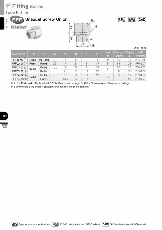
Fitting SeriesTube Fitting
StandardSeries
89
FITTING
Page for special specificationsOP.P.000 3D CAD data is available at PISCO website.CAD
3D CAD CAD data is available at PISCO website.
Unit:mm
Model code Rc1 Rc2 A1 A2 B L øP Hex.H
Orifice bore(ømm)
Weight(g)
CADfile name
PFF01-M5④ Rc1/8 M5×0.8 7 4 17 7 8 14 4.2 12 PFF01-M5
PFF02-01④ Rc1/4 Rc1/8 9.5 7 21 8 14 17 6.5 23 PFF02-01
PFF03-01④Rc3/8
Rc1/810.5
7 22 8 1421
6.5 32 PFF03-01
PFF03-02④ Rc1/4 9.5 25 11 17 9 36 PFF03-02
PFF04-02④Rc1/2
Rc1/413
9.5 30 11 1724
9 51 PFF04-02
PFF04-03④ Rc3/8 10.5 33 14 21 12 58 PFF04-03
※1. ④ in Model code / Replaced with "-C" for Clean-room package, "-UC" for Clean-wash and Clean-room package.
※2. Orifice bore is the smallest passage converted in terms of the diameter.
BA
2
L
A1 H
Rc1
Rc2øP
Unequal Screw UnionPFF OP.P.754 CADCAD
3D
compliant
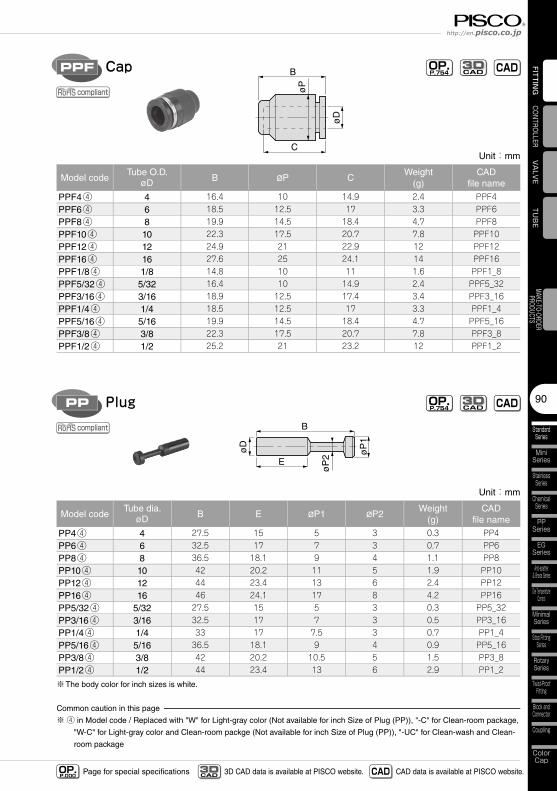
90
StandardSeries
MiniSeries
StainlessSeries
ChemicalSeries
PPSeries
EGSeries
Anti-spatter& Brass Series
Die TemperatureControl
MinimalSeries
Stop FittingSeries
RotarySeries
Twist-ProofFitting
Block andConnector
Coupling
ColorCap
FITTING
TUBE
VALVE
CONTROLLERMAKE-TO-ORDERPRODUCTS
http://en.pisco.co.jp
Page for special specificationsOP.P.000 3D CAD data is available at PISCO website.CAD
3D CAD CAD data is available at PISCO website.
B
C
øD
øP
CapPPF OP.P.754 CADCAD
3D
compliant
Unit:mm
Model codeTube dia.
øD B E øP1 øP2Weight
(g)CAD
file name
PP4④ 4 27.5 15 5 3 0.3 PP4PP6④ 6 32.5 17 7 3 0.7 PP6PP8④ 8 36.5 18.1 9 4 1.1 PP8PP10④ 10 42 20.2 11 5 1.9 PP10PP12④ 12 44 23.4 13 6 2.4 PP12PP16④ 16 46 24.1 17 8 4.2 PP16PP5/32④ 5/32 27.5 15 5 3 0.3 PP5_32PP3/16④ 3/16 32.5 17 7 3 0.5 PP3_16PP1/4④ 1/4 33 17 7.5 3 0.7 PP1_4PP5/16④ 5/16 36.5 18.1 9 4 0.9 PP5_16PP3/8④ 3/8 42 20.2 10.5 5 1.5 PP3_8PP1/2④ 1/2 44 23.4 13 6 2.9 PP1_2
※The body color for inch sizes is white.
Common caution in this page
※ ④ in Model code / Replaced with "W" for Light-gray color (Not available for inch Size of Plug (PP)), "-C" for Clean-room package,
"W-C" for Light-gray color and Clean-room packge (Not available for inch Size of Plug (PP)), "-UC" for Clean-wash and Clean-
room package
B
E
øD
øP
1
øP
2
PlugPP OP.P.754 CADCAD
3D
compliant
Unit:mm
Model codeTube O.D.
øD B øP CWeight
(g)CAD
file name
PPF4④ 4 16.4 10 14.9 2.4 PPF4PPF6④ 6 18.5 12.5 17 3.3 PPF6PPF8④ 8 19.9 14.5 18.4 4.7 PPF8PPF10④ 10 22.3 17.5 20.7 7.8 PPF10PPF12④ 12 24.9 21 22.9 12 PPF12PPF16④ 16 27.6 25 24.1 14 PPF16PPF1/8④ 1/8 14.8 10 11 1.6 PPF1_8PPF5/32④ 5/32 16.4 10 14.9 2.4 PPF5_32PPF3/16④ 3/16 18.9 12.5 17.4 3.4 PPF3_16PPF1/4④ 1/4 18.5 12.5 17 3.3 PPF1_4PPF5/16④ 5/16 19.9 14.5 18.4 4.7 PPF5_16PPF3/8④ 3/8 22.3 17.5 20.7 7.8 PPF3_8PPF1/2④ 1/2 25.2 21 23.2 12 PPF1_2
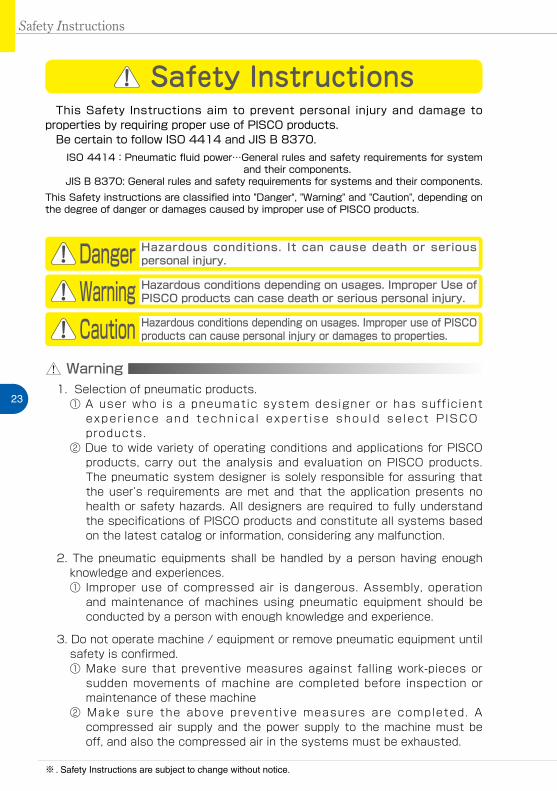
23
Safety Instructions
Safety Instructions
Warning
This Safety Instructions aim to prevent personal injury and damage to properties by requiring proper use of PISCO products. Be certain to follow ISO 4414 and JIS B 8370.
ISO 4414:Pneumatic fluid power…General rules and safety requirements for system and their components.
JIS B 8370: General rules and safety requirements for systems and their components.This Safety instructions are classified into "Danger", "Warning" and "Caution", depending on the degree of danger or damages caused by improper use of PISCO products.
1. Selection of pneumatic products.① A user who is a pneumatic system designer or has sufficient
exper ience and techn ica l expert ise shou ld se lect P ISCO products.
② Due to wide variety of operating conditions and applications for PISCO products, carry out the analysis and evaluation on PISCO products. The pneumatic system designer is solely responsible for assuring that the user’s requirements are met and that the application presents no health or safety hazards. All designers are required to fully understand the specifications of PISCO products and constitute all systems based on the latest catalog or information, considering any malfunction.
2. The pneumatic equipments shall be handled by a person having enough knowledge and experiences.① Improper use of compressed air is dangerous. Assembly, operation
and maintenance of machines using pneumatic equipment should be conducted by a person with enough knowledge and experience.
3. Do not operate machine / equipment or remove pneumatic equipment until safety is confirmed.① Make sure that preventive measures against falling work-pieces or
sudden movements of machine are completed before inspection or maintenance of these machine
② Make sure the above preventive measures are completed. A compressed air supply and the power supply to the machine must be off, and also the compressed air in the systems must be exhausted.
Danger Hazardous conditions. It can cause death or serious personal injury.
Warning Hazardous conditions depending on usages. Improper Use of PISCO products can case death or serious personal injury.
Caution Hazardous conditions depending on usages. Improper use of PISCO products can cause personal injury or damages to properties.
※ . Safety Instructions are subject to change without notice.
http://www.pisco.co.jphttp://en.pisco.co.jp
24
Warranty
Disclaimer
1. When the product produces a trouble, which is caused by our responsibility, we will carry out either one of the following measures immediately.① Free-of-charge replacement of same product② Free-of-charge repair of the product at our factory
③ Restart the machines with care after ensuring to take all preventive measures against sudden movements.
When a cause of the trouble/malfunction applies to any of the following items, it is excluded from the coverage of the above warranty.
①. A case by a natural disaster, a fire except our responsibility, the act by the third person/party, the intention or fault of the customer.
②. A case when a product is used out of the specific range or in a method listed in the product catalog or the instruction manual.
③. A case by the remodeling of the product or by a change of structure, performance, or specifications which PISCO is not involved in.
④. A case by the event that is unpredictable by the evaluations and the measures at the time on or before the initial delivery.
⑤. A case caused by the phenomenon that is able to be evaded if your machine or equipment has functions or structures that are comprised in a common sense when this product is incorporated in your machine or equipment.
Additionally, the above warranty is limited simply to the product itself. The damage induced by the trouble of the product will not be compensated.
25
Common Safety Instructions for Products Listed in This Catalog
Common Safety Instructions for Products Listed in This Catalog
Danger1. Do not use PISCO products for the following applications.
① Equipment used for maintaining / handling human life and body.② Equipment used for moving / transporting human.③ Equipment specifically used for safety purposes.
Warning1. Do not use PISCO products under the following conditions.
① Beyond the specifications or conditions stated in the catalog, or the instructions.
② Use at outdoors.③ Excessive vibrations and impacts.④ Exposure / adhere to corrosive gas, flammable gas, chemicals,
seawater, water and vapor. * Some products can be used under the condition above(④). Refer to
the details of specifications and conditions of each product.
2. Do not disassemble or modify PISCO products, which affect the performance, function, and basic structure of the product.
3. Do not touch the release-ring of a push-in fitting when there is a working pressure. The lock may be released by the physical contact, and tube may fly out or slip out.
4. Frequent switchover of compressed air may generate heat, and there is a risk of causing burn injury.
5. Avoid any load on PISCO products, such as, a tensile strength, twisting and bending.
6. As for applications where threads or tubes swing / rotate, use Rotary Joints, High Rotary Joints or Multi-Circuit Rotary Block only. The other PISCO products can be damaged in these applications.
7. Use only Die Temperature Control Fitting Series, Tube Fitting Stainless SUS316 Series, Tube Fitting Stainless SUS316 Compression Fitting Series or Tube Fitting Brass Series under the condition of over 60℃ (140°F) water or heat medium oil. Other PISCO products can be damaged by heat and hydrolysis under the condition above.
8. As for the condition required to dissipate static electricity or provide an antistatic performance, use EG series fitting and antistatic products only, and do not use other PISCO products. There is a risk that static electricity
PISCO products are designed and manufactured for use in general industrial machines.
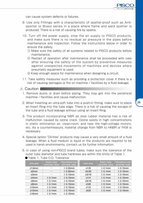
http://www.pisco.co.jphttp://en.pisco.co.jp
26
Caution1. Remove dusts or drain before piping. They may get into the peripheral
machine / facilities and cause malfunction.
2. When inserting an ultra-soft tube into a push-in fitting, make sure to place an Insert Ring into the tube edge. There is a risk of causing the escape of the tube and a fluid leakage without using an Insert Ring.
3. The product incorporating NBR as seal rubber material has a risk of malfunction caused by ozone crack. Ozone exists in high concentrations in static elimination air, clean-room, and near the high-voltage motors, etc. As a countermeasure, material change from NBR to HNBR or FKM is necessary.
4. Special option “Oil-free” products may cause a very small amount of a fluid leakage. When a fluid medium is liquid or the products are required to be used in harsh environments, contact us for further information.
5. In case of using non-PISCO brand tubes, make sure the tolerance of the outer tube diameter and tube hardness are within the limits of Table 1.
●Table 1. Tube O.D. Tolerance
mm size Nylon tube(SHORE D63)
Polyurethane tube(SHORE A98) inch size Nylon tube
(SHORE D63)Polyurethane tube(SHORE A98)
ø1.8mm ─ ±0.05mm ø1/8 ±0.1mm ±0.15mmø2mm ─ ±0.05mm ø5/32 ±0.1mm ±0.15mmø3mm ─ ±0.15mm ø3/16 ±0.1mm ±0.15mmø4mm ±0.1mm ±0.15mm ø1/4 ±0.1mm ±0.15mmø6mm ±0.1mm ±0.15mm ø5/16 ±0.1mm ±0.15mmø8mm ±0.1mm ±0.15mm ø3/8 ±0.1mm ±0.15mmø10mm ±0.1mm ±0.15mm ø1/2 ±0.1mm ±0.15mmø12mm ±0.1mm ±0.15mm ø5/8 ±0.1mm ±0.15mmø16mm ±0.1mm ±0.15mm
can cause system defects or failures.
9. Use only Fittings with a characteristic of spatter-proof such as Anti-spatter or Brass series in a place where flame and weld spatter is produced. There is a risk of causing fire by sparks.
10. Turn off the power supply, stop the air supply to PISCO products, and make sure there is no residual air pressure in the pipes before maintenance and inspection. Follow the instructions below in order to ensure the safety.① Make sure the safety of all systems related to PISCO products before
maintenance.② Restart of operation after maintenance shall be proceeded with care
after ensuring the safety of the system by preventive measures against unexpected movements of machines and devices where pneumatic equipment is used.
③ Keep enough space for maintenance when designing a circuit.
11. Take safety measures such as providing a protection cover if there is a risk of causing damages or fire on machine / facilities by a fluid leakage.
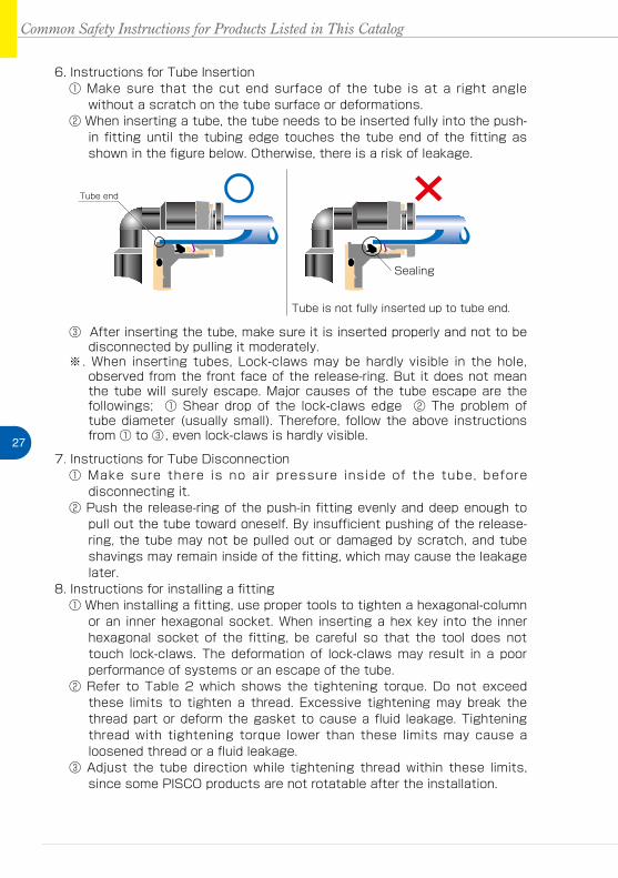
27
Common Safety Instructions for Products Listed in This Catalog
6. Instructions for Tube Insertion① Make sure that the cut end surface of the tube is at a right angle
without a scratch on the tube surface or deformations.② When inserting a tube, the tube needs to be inserted fully into the push-
in fitting until the tubing edge touches the tube end of the fitting as shown in the figure below. Otherwise, there is a risk of leakage.
③ After inserting the tube, make sure it is inserted properly and not to be disconnected by pulling it moderately.
※. When inserting tubes, Lock-claws may be hardly visible in the hole, observed from the front face of the release-ring. But it does not mean the tube will surely escape. Major causes of the tube escape are the followings; ① Shear drop of the lock-claws edge ② The problem of tube diameter (usually small). Therefore, follow the above instructions from ① to ③, even lock-claws is hardly visible.
7. Instructions for Tube Disconnection① Make sure there is no air pressure inside of the tube, before
disconnecting it.② Push the release-ring of the push-in fitting evenly and deep enough to
pull out the tube toward oneself. By insufficient pushing of the release-ring, the tube may not be pulled out or damaged by scratch, and tube shavings may remain inside of the fitting, which may cause the leakage later.
8. Instructions for installing a fitting① When installing a fitting, use proper tools to tighten a hexagonal-column
or an inner hexagonal socket. When inserting a hex key into the inner hexagonal socket of the fitting, be careful so that the tool does not touch lock-claws. The deformation of lock-claws may result in a poor performance of systems or an escape of the tube.
② Refer to Table 2 which shows the tightening torque. Do not exceed these limits to tighten a thread. Excessive tightening may break the thread part or deform the gasket to cause a fluid leakage. Tightening thread with tightening torque lower than these limits may cause a loosened thread or a fluid leakage.
③ Adjust the tube direction while tightening thread within these limits, since some PISCO products are not rotatable after the installation.
Tube end
Sealing
Tube is not fully inserted up to tube end.
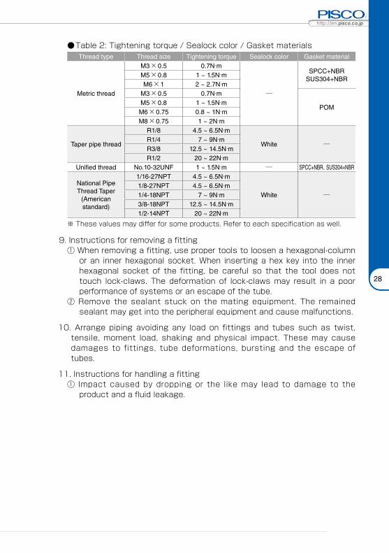
http://www.pisco.co.jphttp://en.pisco.co.jp
28
●Table 2: Tightening torque / Sealock color / Gasket materialsThread type Thread size Tightening torque Sealock color Gasket material
Metric thread
M3×0.5 0.7N·m
─
SPCC+NBRSUS304+NBR
M5×0.8 1 ~ 1.5N·mM6×1 2 ~ 2.7N·m
M3×0.5 0.7N·m
POMM5×0.8 1 ~ 1.5N·mM6×0.75 0.8 ~ 1N·mM8×0.75 1 ~ 2N·m
Taper pipe thread
R1/8 4.5 ~ 6.5N·m
White ─R1/4 7 ~ 9N·mR3/8 12.5 ~ 14.5N·mR1/2 20 ~ 22N·m
Unified thread No.10-32UNF 1 ~ 1.5N·m ─ SPCC+NBR、SUS304+NBR
National Pipe Thread Taper
(American standard)
1/16-27NPT 4.5 ~ 6.5N·m
White ─1/8-27NPT 4.5 ~ 6.5N·m1/4-18NPT 7 ~ 9N·m3/8-18NPT 12.5 ~ 14.5N·m1/2-14NPT 20 ~ 22N·m
※ These values may differ for some products. Refer to each specification as well.
9. Instructions for removing a fitting① When removing a fitting, use proper tools to loosen a hexagonal-column
or an inner hexagonal socket. When inserting a hex key into the inner hexagonal socket of the fitting, be careful so that the tool does not touch lock-claws. The deformation of lock-claws may result in a poor performance of systems or an escape of the tube.
② Remove the sealant stuck on the mating equipment. The remained sealant may get into the peripheral equipment and cause malfunctions.
10. Arrange piping avoiding any load on fittings and tubes such as twist, tensile, moment load, shaking and physical impact. These may cause damages to fittings, tube deformations, bursting and the escape of tubes.
11. Instructions for handling a fitting① Impact caused by dropping or the like may lead to damage to the
product and a fluid leakage.
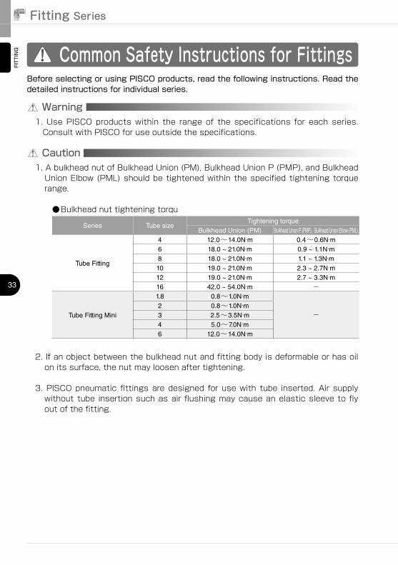
Fitting SeriesFITTING
33
Common Safety Instructions for Fittings
Warning
Before selecting or using PISCO products, read the following instructions. Read the detailed instructions for individual series.
1.��Use�PISCO�products�within� the� range�of� the� specifications� for� each� series.�Consult�with�PISCO�for�use�outside�the�specifications.
Caution1.�A�bulkhead�nut�of�Bulkhead�Union�(PM),�Bulkhead�Union�P�(PMP),�and�Bulkhead�Union�Elbow�(PML)�should�be�tightened�within�the�specified�tightening�torque�range.
●Bulkhead�nut�tightening�torqu
Series Tube sizeTightening torque
Bulkhead Union (PM) Bulkhead Union P (PMP)、Bulkhead Union Elbow (PML)
Tube Fitting
4 12.0~14.0N·m 0.4~0.6N·m6 18.0 ~ 21.0N·m 0.9 ~ 1.1N·m8 18.0 ~ 21.0N·m 1.1 ~ 1.3N·m10 19.0 ~ 21.0N·m 2.3 ~ 2.7N·m12 19.0 ~ 21.0N·m 2.7 ~ 3.3N·m16 42.0 ~ 54.0N·m -
Tube Fitting Mini
1.8 0.8~1.0N·m
-2 0.8~1.0N·m3 2.5~3.5N·m4 5.0~7.0N·m6 12.0~14.0N·m
2.�If�an�object�between�the�bulkhead�nut�and�fitting�body�is�deformable�or�has�oil�on�its�surface,�the�nut�may�loosen�after�tightening.
3.�PISCO�pneumatic� fittings�are�designed� for�use�with� tube� inserted.�Air�supply�without�tube� insertion�such�as�air� flushing�may�cause�an�elastic�sleeve�to�fly�out�of�the�fitting.
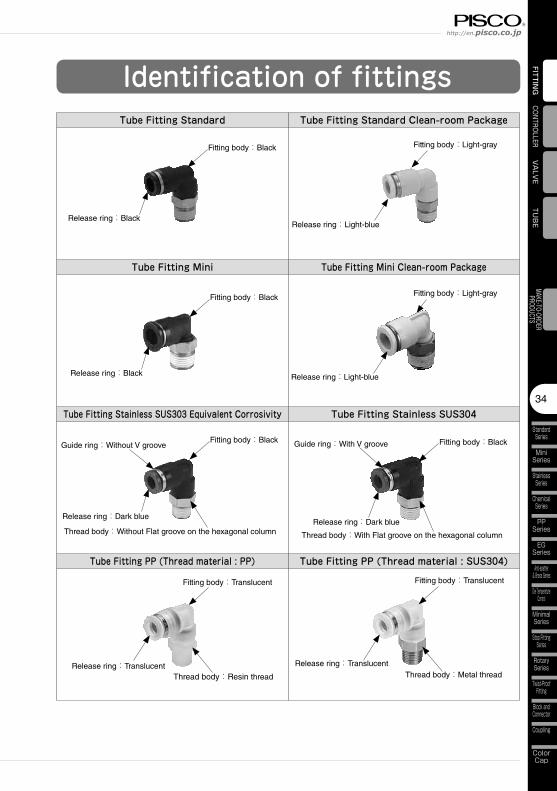
FITTING
TUBE
VALVE
CONTROLLER
StandardSeries
MiniSeries
StainlessSeries
ChemicalSeries
PPSeries
EGSeries
Anti-spatter& Brass Series
Die TemperatureControl
MinimalSeries
Stop FittingSeries
RotarySeries
Twist-ProofFitting
Block andConnector
Coupling
ColorCap
34
MAKE-TO-ORDERPRODUCTS
http://en.pisco.co.jp
Identification of fittingsTube Fitting Standard Tube Fitting Standard Clean-room Package
Tube Fitting Mini Tube Fitting Mini Clean-room Package
Tube Fitting Stainless SUS303 Equivalent Corrosivity Tube Fitting Stainless SUS304
Tube Fitting PP (Thread material : PP) Tube Fitting PP (Thread material : SUS304)
Fitting body:Black
Release ring:BlackRelease ring:Light-blue
Fitting body:Black
Release ring:Black
Fitting body:Black
Release ring:Dark blue
Thread body:Without Flat groove on the hexagonal column
Guide ring:Without V groove Fitting body:Black
Release ring:Dark blue
Thread body:With Flat groove on the hexagonal column
Guide ring:With V groove
Fitting body:Translucent
Release ring:TranslucentThread body:Resin thread
Fitting body:Translucent
Release ring:TranslucentThread body:Metal thread
Fitting body:Light-gray
Release ring:Light-blue
Fitting body:Light-gray

Make-to-orderproducts
http://en.pisco.co.jp
754
MAKE-TO-ORDERPRODUCTS
PISCO offers make-to-order products
to support customer's various requirements
such as special specifications,
and special appearances.
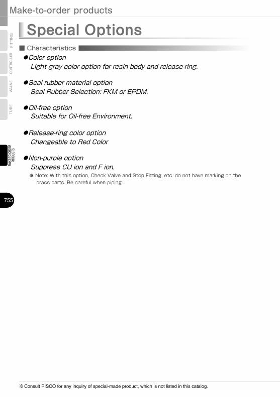
Make-to-order products
755
MAKE-TO-ORDER
PRODUCTS
TUBE
VALVE
CONTROLLER
FITTING
※Consult PISCO for any inquiry of special-made product, which is not listed in this catalog.
■ Characteristics ●Color option Light-gray color option for resin body and release-ring.
●Seal rubber material option Seal Rubber Selection: FKM or EPDM.
●Oil-free option Suitable for Oil-free Environment.
●Release-ring color option Changeable to Red Color
●Non-purple option Suppress CU ion and F ion.
※ Note: With this option, Check Valve and Stop Fitting, etc. do not have marking on the brass parts. Be careful when piping.
Special Options
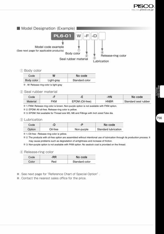
http://en.pisco.co.jp
756
MAKE-TO-ORDERPRODUCTS
■ Model Designation (Example)
PL6-01
Model code example(See next page for applicable products) ①
Body color
※. See next page for “Reference Chart of Special Option” .※. Contact the nearest sales office for the price.
W
②Seal rubber material
-F
③Lubrication
-D
④Release-ring color
① Body colorCode W No code
Body color Light-gray Standard color
※ . W: Release-ring color is light-gray
② Seal rubber materialCode -F -E -HN No code
Material FKM EPDM (Oil-free) HNBR Standard seal rubber
※ 1. FKM: Release-ring color is brown. Non-purple option is not available with FKM option.
※ 2. EPDM: All oil-free. Release-ring color is yellow.
※ 3. EPDM: Not available for Thread size M3, M6 and Fittings with Inch sized Tube dia.
③ LubricationCode -D -P No code
Option Oil-free Non-purple Standard lubrication
※ 1. Oil-free : Release-ring color is yellow.
※ 2. The products with oil-free option are assembled without intentional use of lubrication through its production process. It
may cause problems such as degradation of airtightness and increase of friction.
※ 3. Non-purple option is not available with FKM option. No sealock coat is provided on the thread.
④ Release-ring colorCode -RR No codeColor Red Standard color
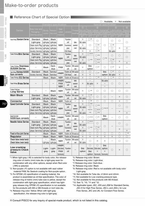
Make-to-order products
757
MAKE-TO-ORDER
PRODUCTS
TUBE
VALVE
CONTROLLER
FITTING
※Consult PISCO for any inquiry of special-made product, which is not listed in this catalog.
■ Reference Chart of Special Option○:Available、×:Not available
Series
Standard specification Special specification
Body Color and Packaging /
Cleaning option
Body color
Release-ring color
Seal rubber
materialLubrication Thread
sealing
① Body color
② Seal rubber material
③ Lubrication
④ Release-ring color
Light-gray FKM EPDM HNBR Oil-free Non-Purple RedW*1 -F*2 -E*3 -HN -D*4 -P*2 -RR
Tube Fitting Standard Series Standard Black Black
NBR
Turbin oil With
sealock coat
× ○ *5
○
○
○ ○ ○Light-gray Light-gray Light-gray Std. option○Clean-room Pkg Light-gray Light-blue Fluorochemical
grease× ○ *6 ○ *6
×Light-gray + Clean-room pkg Light-gray Light-gray Std. option ○ ○ ×Clean washing + Clean-room pkg Light-gray Light-blue Oil-free × × ○ *6 Std. option ○
Tube Fitting Mini Series Standard Black Black
NBR
Turbin oil
With sealock
coat
× ○ *5,*10
○ *10
○ *10
○ ○ ○Light-gray Light-gray Light-gray Std. option○ *10Clean-room Pkg Light-gray Light-blue Fluorochemical
grease× ○ *6,*10 ○ *6
×Light-gray + Clean-room pkg Light-gray Light-gray Std. option ○ *10 ○ ×
Tube Fitting Stainless SUS304 Series - Black
Dark-blue
FKMTurbin
oilWith sealock
coat× Std.
option○ *7 ○ ○ *7 × -
Tube Fitting Stainless SUS303 Equiv. corrosivity
Standard Black Dark-blueHNBR
Turbin oil With sealock coat
○ ○ ○ *7 Std. option
○ *7 ○ ○Clean washing + Clean-room pkg Black Dark-blue Oil-free × × Std. option ×
Tube Fitting EG Series - Black Black NBR Turbin oil With sealock coat × ○ ○ *8 ○ ○ *8 ○ -
Tube Fitting Brass Series - - -HNBR
Turbin oil
With sealock
coat×
-×
Std. option○ ○ ×FKM Std. option -
NBR - -Tube Fitting Long Series - - Black NBR
Turbin oil
With sealock coat
× ○ *5 ○ ○ ○ ○ ○
Main Block Standard Black BlackNBR
Turbin oil
With sealock coat
× ○ *5
○ ○ - × ○Light-gray Light-gray Light-gray Std. option ○
Connector - Black Black NBR Turbin oil - × ○ *5 ○ ○ ○ × ○Speed Controller Series Standard Black Black
NBR
Turbin oil
With sealock
coat
× ○ *13
○ *10
○ *10,*11 -○ ○Light-gray Light-gray Light-gray Std. option ○
*10,*11
*12
Clean-room Pkg Light-gray Light-blue Fluorochemical grease
× ○ *6,*10
×Light-gray + Clean-room pkg Light-gray Light-gray Std. option ○ *10 ×
Speed Controller SUS303 Equiv. corrosivity - Black
Dark-blue
HNBRTurbin
oilWith sealock
coat○ ○ *11,*12 ○ *7 Std.
option- ○ ○
Needle Valve Series Standard Black Black
NBR
Turbin oil
With sealock
coat
× ○ *5,*12
○○ -
○ ○Light-gray Light-gray Light-gray Std. option○ *12Clean-room Pkg Light-gray Light-blue Fluorochemical
grease× ○ *6
×Light-gray + Clean-room pkg Light-gray Light-gray Std. option ○ ×
Fixed orifice joint Series - Black Black NBR Turbin oil With sealock coat ○ ○ ○ ○ ○ ○ ○ *9
Regulator - Black Black NBR Turbin oil With sealock coat × × × × × ○ ○Check Valve (metal body) - - Black
NBRTurbin
oilWith sealock
coat× ○ × × - ○ ○Check Valve (resin body) Light-gray Light-gray Std. option
Low cracking pressure Check Valve
- Light-gray
Light-gray
HNBR (Elastic sleeve) Turbin
oil- Std.
option
○ (Elastic sleeve)
○ (Elastic sleeve)
Std. option
○ × ○FKM
(Poppet valve packing)Std.
option×
(Poppet valve packing)×
(Poppet valve packing)
*1. When light-gray (-W) is selected for body color, the release-ring color of metric (mm) tube dia. is light-gray even for combination with any other options, except when Red color (-RR) is selected.
*2. Non-purple (-P) option is not available with seal rubber material FKM. No Sealock coating for Non-purple option.
*3. For EPDM (-E) specification of sealing material, the product is assembled as oil-free specification. The color of release-ring of metric (mm) tube size is yellow, except the combination with light-gray specification, which has light-gray release-ring. EPDM (-E) specification is not available for the products with M3 or M6 threads or inch tube dia.
*4. Release-ring color: Yellow. When with light-gray specification, the release-ring color is light-gray.
*5. Release-ring color: Brown.*6. Release-ring color: Light-blue.*7. Release-ring color: Dark-blue.*8. Release-ring color: Black*9. Release-ring color: Red is not available with body color
Light-gray.*10. Not available for Tube dia. ø1.8mm and ø2mm.*11. Not available for Low cracking pressure type.*12. Not available for the products with M3 thread.*13. See *5, *10, *11 and *12.*14. Applicable types: JSC, JSS and JSM for Standard Series,
JSC-H for High Flow Series, JSC-L and JSS-L for Low Flow Series, JKC and JKL for Constant Flow Series.
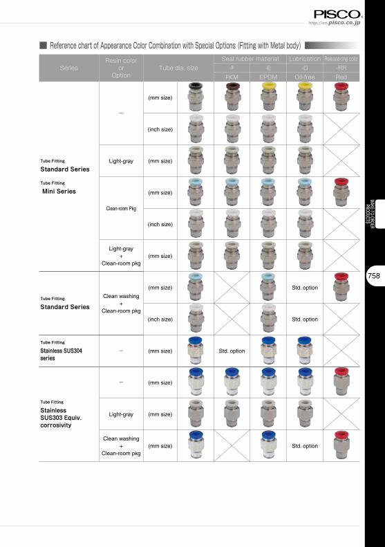
http://en.pisco.co.jp
758
MAKE-TO-ORDERPRODUCTS
■ Reference chart of Appearance Color Combination with Special Options (Fitting with Metal body)
SeriesResin color
orOption
Tube dia. sizeSeal rubber material Lubrication Release-ring color
-F -E -D -RRFKM EPDM Oil-free Red
Tube Fitting
Standard Series
Tube Fitting
Mini Series
-
(mm size)
(inch size)
Light-gray (mm size)
Clean-room Pkg
(mm size)
(inch size)
Light-gray+
Clean-room pkg(mm size)
Tube Fitting
Standard Series
Clean washing+
Clean-room pkg
(mm size) Std. option
(inch size) Std. option
Tube Fitting
Stainless SUS304 series
- (mm size) Std. option
Tube Fitting
Stainless SUS303 Equiv. corrosivity
- (mm size)
Light-gray (mm size)
Clean washing+
Clean-room pkg(mm size) Std. option
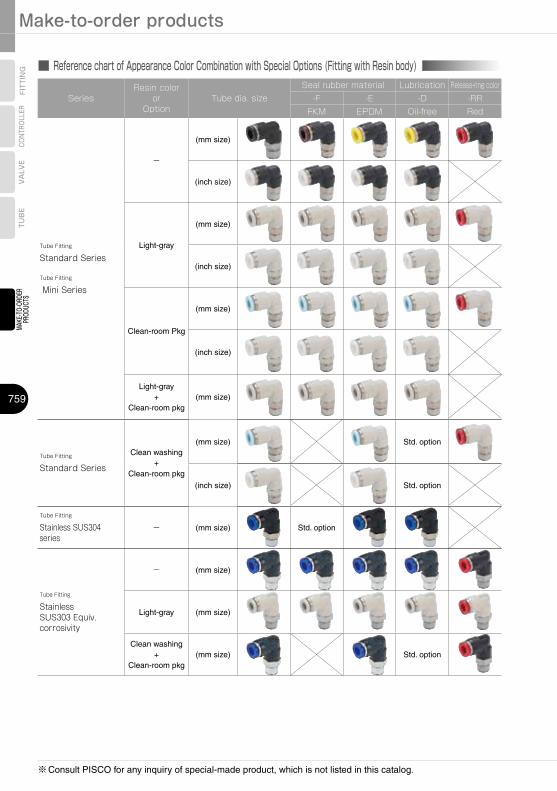
Make-to-order products
759
MAKE-TO-ORDER
PRODUCTS
TUBE
VALVE
CONTROLLER
FITTING
※Consult PISCO for any inquiry of special-made product, which is not listed in this catalog.
■ Reference chart of Appearance Color Combination with Special Options (Fitting with Resin body)
SeriesResin color
orOption
Tube dia. sizeSeal rubber material Lubrication Release-ring color
-F -E -D -RRFKM EPDM Oil-free Red
Tube Fitting
Standard Series
Tube Fitting
Mini Series
-
(mm size)
(inch size)
Light-gray
(mm size)
(inch size)
Clean-room Pkg
(mm size)
(inch size)
Light-gray+
Clean-room pkg(mm size)
Tube Fitting
Standard Series
Clean washing+
Clean-room pkg
(mm size) Std. option
(inch size) Std. option
Tube Fitting
Stainless SUS304 series
- (mm size) Std. option
Tube Fitting
Stainless SUS303 Equiv. corrosivity
- (mm size)
Light-gray (mm size)
Clean washing+
Clean-room pkg(mm size) Std. option
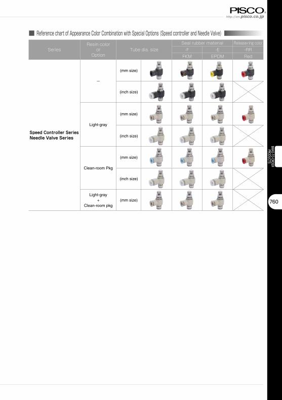
http://en.pisco.co.jp
760
MAKE-TO-ORDERPRODUCTS
■ Reference chart of Appearance Color Combination with Special Options (Speed controller and Needle Valve)
SeriesResin color
orOption
Tube dia. sizeSeal rubber material Release-ring color
-F -E -RRFKM EPDM Red
Speed Controller SeriesNeedle Valve Series
-
(mm size)
(inch size)
Light-gray
(mm size)
(inch size)
Clean-room Pkg
(mm size)
(inch size)
Light-gray+
Clean-room pkg(mm size)
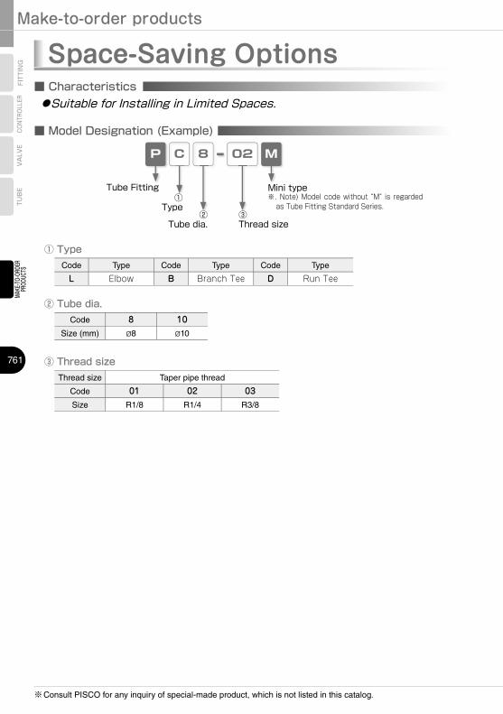
Make-to-order products
761
MAKE-TO-ORDER
PRODUCTS
TUBE
VALVE
CONTROLLER
FITTING
※Consult PISCO for any inquiry of special-made product, which is not listed in this catalog.
■ Characteristics
Space-Saving Options ●Suitable for Installing in Limited Spaces.
■ Model Designation (Example)
CP 8 02
② Tube dia.
③ Thread size
Code 8 10Size (mm) ø8 ø10
Thread size Taper pipe thread
Code 01 02 03Size R1/8 R1/4 R3/8
Code Type Code Type Code Type
L Elbow B Branch Tee D Run Tee
① Type
M
Tube Fitting①
Type②
Tube dia.③Thread size
Mini type※. Note) Model code without “M” is regarded
as Tube Fitting Standard Series.
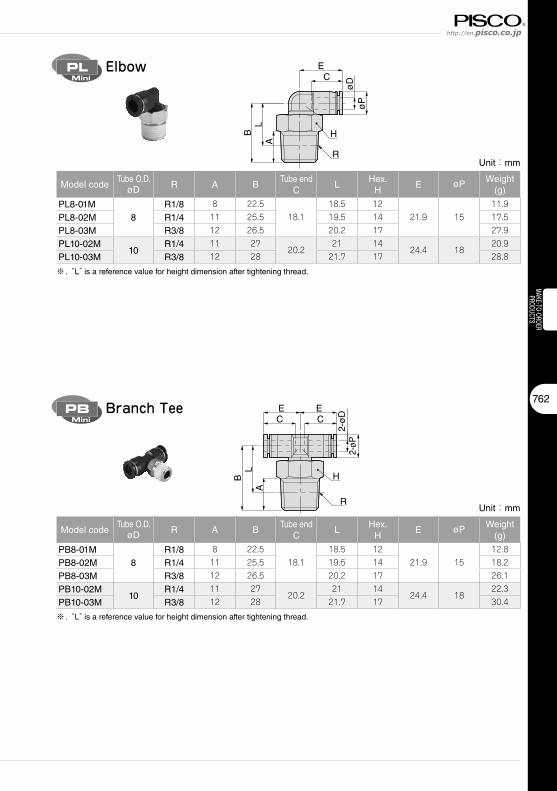
http://en.pisco.co.jp
762
MAKE-TO-ORDERPRODUCTS
PL
Unit:mm
Model codeTube O.D.
øD R A BTube end
CL
Hex.H
E øP Weight(g)
PL8-01M8
R1/8 8 22.518.1
18.5 1221.9 15
11.9
PL8-02M R1/4 11 25.5 19.5 14 17.5
PL8-03M R3/8 12 26.5 20.2 17 27.9
PL10-02M10
R1/4 11 2720.2
21 1424.4 18
20.9
PL10-03M R3/8 12 28 21.7 17 28.8
※ . “L” is a reference value for height dimension after tightening thread.A
EC
R
øP
øD
LB H
ElbowMini
PB
A
R
E ECC
2-ø
D2-
øP
LB H
Branch TeeMini
Unit:mm
Model codeTube O.D.
øD R A BTube end
CL
Hex.H
E øP Weight(g)
PB8-01M8
R1/8 8 22.518.1
18.5 1221.9 15
12.8
PB8-02M R1/4 11 25.5 19.5 14 18.2
PB8-03M R3/8 12 26.5 20.2 17 26.1
PB10-02M10
R1/4 11 2720.2
21 1424.4 18
22.3
PB10-03M R3/8 12 28 21.7 17 30.4
※ . “L” is a reference value for height dimension after tightening thread.
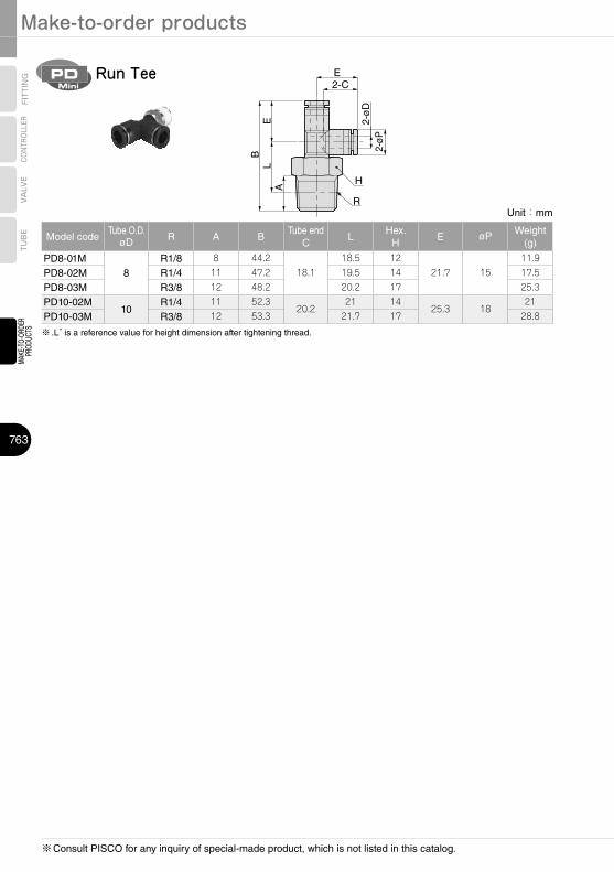
Make-to-order products
763
MAKE-TO-ORDER
PRODUCTS
TUBE
VALVE
CONTROLLER
FITTING
※Consult PISCO for any inquiry of special-made product, which is not listed in this catalog.
PD
Unit:mm
Model codeTube O.D.
øD R A BTube end
CL
Hex.H
E øP Weight(g)
PD8-01M8
R1/8 8 44.218.1
18.5 1221.7 15
11.9
PD8-02M R1/4 11 47.2 19.5 14 17.5
PD8-03M R3/8 12 48.2 20.2 17 25.3
PD10-02M10
R1/4 11 52.320.2
21 1425.3 18
21
PD10-03M R3/8 12 53.3 21.7 17 28.8
※ .L” is a reference value for height dimension after tightening thread.
A
R
E 2-ø
D2-
øP
E2-C
LB
H
Run TeeMini


![GRP FITTING - STANDARD DIMENSIONS · GRP PIPE FIITINGS CATALOUGE Shriram SEPL Composites (P) Ltd., Chennai GRP FITTING - STANDARD DIMENSIONS BEND [PLAIN END] DIMENSIONS – STD “L”](https://img.pdfslide.us/doc/110x75/5e7db55f3e68b17160355aaf/grp-fitting-standard-grp-pipe-fiitings-catalouge-shriram-sepl-composites-p-ltd.jpg)