Embed Size (px)
Citation preview

April 19, 1991 Dear Reader: These Standard References for Monitoring Wells, WSC-310-91, describe the technical requirements for locating, drilling, installing, sampling and decommissioning monitoring wells. Standard References for Monitoring Wells was developed to help ensure data used for environmental monitoring purposes is valid and can be interpreted consistently by anyone assessing groundwater, including Department staff, consultants, drillers and firms performing these assessments. Many people, from within and outside the Department, were involved in developing this technical document. These References represent the Department's current understanding of the art of groundwater monitoring. We welcome any information on innovative field techniques, suggestions for updates, or comments. This document will be updated to reflect new information about emerging technologies as our resources permit. These References are one of several initiatives the Department is undertaking to provide clear, practical guidance for those affected by Massachusetts environmental regulations. We hope that you find this document a valuable tool.

COMMONWEALTH OF MASSACHUSETTS DEPARTMENT OF ENVIRONMENTAL PROTECTION
STANDARD REFERENCES FOR MONITORING WELLS WSC–310-91

DEDICATION This document is dedicated with great affection to Dodie Brownlee. She pioneered hydrogeology in the Department of Environmental Protection. Dodie worked tirelessly to protect and improve our environment. Dodie Brownlee conceived and developed these Standard References for Monitoring Wells. She worked on them until her death in the spring of 1990. May her spirit of commitment and drive for excellence live on through all of us.

COMMONWEALTH OF MASSACHUSETTS
DEPARTMENT OF ENVIRONMENTAL PROTECTION
STANDARD REFERENCES FOR MONITORING WELLS
SECTION 1.1 FOREWORD

Section 1.1 Page i
January 1991 SECTION 1.1 FOREWORD TABLE OF CONTENTS Section Title Page No. 1.1-1 PURPOSE ....................................................................................... 1 1.1-2 ORDER OF PRESENTATION......................................................... 1 1.1-3 DEPARTMENTAL USE OF STANDARD REFERENCES............... 2 1.1-3.1 Statement by Division of Water Pollution Control (DWPC).............. 2 1.1-3.2 Statement by Division of Water Supply (DWS)................................ 2 1.1-3.3 Statement by Division of Hazardous (DHW).................................... 2 1.1-3.4 Statement by Bureau of Waste Site Cleanup (BWSC) .................... 4 1.1-3.4.1 The Massachusetts Contingency Plan ............................................ 4 1.1-3.4.2 Long-term Monitoring....................................................................... 4 1.1-4 REVISIONS AND SUGGESTIONS ................................................. 5 ADDITIONAL REFERENCES.......................................................... 6

Section 1.1 Page 1 January 1991
SECTION 1.1 FOREWORD 1.1-1 PURPOSE These Standard References (SRs) covering the technical aspects of locating, drilling, installing, sampling, and decommissioning of monitoring wells have been prepared by the Department of Environmental Protection (DEP) to provide guidance to employees of the Department, consultants, drillers, and members of the regulated community. Monitoring wells may be installed for a variety of reasons including observation of drawdown during a pumping test, determination of groundwater quality, estimation of hydraulic conductivity using permeability tests, determination of ground water flow directions and rates of flow, and monitoring impacts of various activities on the hydraulic head. Some monitoring wells are installed primarily for geochemical monitoring of uncontaminated ground water to serve as baseline data, as well as providing background values against which potential impacts on ground water can be measured. In some cases, chemical sampling is not part of a monitoring program. If ground water chemistry and contaminant characteristics are not matters of concern, then the monitoring well network may be designed with a minimum amount of information, primarily the site geology and hydrology. An in-depth discussion of monitoring well network design can be found in Section 4.1 of these Standard References. The impetus for writing these SRs came from frequent observations of improperly sited, improperly constructed, and improperly sampled monitoring wells. Such wells do not produce valid data for environmental monitoring purposes. In order to improve the quality of the data collection and of the Department's interpretation of environmental monitoring reports, the writing of these SRs was undertaken. 1.1-2 ORDER OF PRESENTATION This introductory section contains the full Table of Contents (Section 1.2) and Definitions (Section 1.3). The sections and subsections in the Table of Contents have been assembled in the order in which one typically proceeds when undertaking a hydrogeologic investigation: from site reconnaissance to drilling, to well installation, to ground water sampling. Geophysical techniques, which may be employed during any phase of a site assessment, can be found in a separate section at the end of the document. It was the authors' decision that each section should be able to stand alone as a reference on a given topic. For that reason, the user will find that this document contains some deliberate redundancies. Cross-references are provided to other sections where a similar subject is discussed. Most subsections started from a predetermined format: Purpose, Methodology, Problems and Solutions, and References. For editorial simplicity, the figures and tables for each section follow the text rather than being inserted into it. The section on Purpose is designed to present a set of standards to be achieved (i.e., performance standards). The section on Methodology contains some examples of current, acceptable methods for attaining these standards. The methodology does not attempt to be all-encompassing; it seeks to be illustrative. Other techniques which achieve an equivalent degree of compliance with the standard should be equally acceptable. Each subsection has been assigned its own unique number. Each page within a subsection contains the subsection number, page number, and date. It is anticipated

Section 1.1 Page 2 January 1991
that this document will be expanded and updated in the future by the addition of new subsection pages with new dates. The figures and tables all carry the subsection designation number plus a figure or table number. They also display a consecutive page number. Perhaps an example will clarify this point: the second figure in Section 7.1 would be numbered Figure 7.1-2; the page number might be 24, and the date January 1991. A loose-leaf format has been chosen to facilitate updating these SRs. The old page should be removed and discarded. The new insert should replace it. It is anticipated that this system may require the use of pages with suffixes such as 4(a), 4(b), etc., so that the original pagination will not be affected. 1.1-3 DEPARTMENTAL USE OF STANDARD REFERENCES 1.1-3.1 Statement by Division of Water Pollution Control (DWPC) These SRs can serve as a general reference for hydrogeologic investigation techniques. For more specific guidance on submitting hydrogeologic reports, siting discharge points, and designing monitoring well networks in connection with ground water discharge permits, the reader is directed to the following:
• DWPC Policy Memorandum #GW88-1, "Guidelines for siting disposal areas for wastewater treatment plants," 12/1/88.
• DWPC Policy Memorandum #GW88-2, "Monitoring well plan guidelines," 12/1/88.
• "Guidelines for the design, location, operation and maintenance of small sewage
treatment plant facilities with land disposal," second draft, January 1988. Information concerning these publications or other Divisional policies and issues is available from the Ground Water Section at the Division's Boston Office, 1 Winter Street, Boston, MA 02108. 1.1-3.2 Statement by Division of Water Supply (DWS) Several programs administered by the Division of Water Supply may utilize observation wells or monitoring wells as a means of obtaining information related to the quantity and/or quality of drinking water supplies within the State. These programs include, but are not limited to, Aquifer Land Acquisition, New Source Approval, Water Management Act Permitting, and Water Supply Contamination Correction. For such programs, the Standard References are applicable as general guidance. To obtain information regarding specific policies and guidance documents, contact the Division of Water Supply at the Department's Boston office. 1.1-3.3 Statement by Division of Hazardous Waste (DHW) In 1979, Massachusetts enacted M.G.L. c. 21C, the Hazardous Waste Management Act. This act was intended to be equivalent to Subtitle C of the Resource Conservation and Recovery Act (RCRA) passed by the United States Congress in 1976. In 1982, the DEP promulgated regulations (310 CMR 30.000) to enforce the M.G.L. c. 21C statute. This

Section 1.1 Page 3 January 1991
enabled the state to obtain from EPA authorization to implement the RCRA hazardous waste management program in the state. Ground water protection is a key component of RCRA and M.G.L. c. 21C. Under 310 CMR 30.000, ground water monitoring is required at all hazardous waste disposal facilities and may be required at treatment and storage facilities, if there is a threat to the environment. Ground water monitoring, according to the regulations, can be broken down into two main components:
• Detection monitoring (i.e., detecting a release)
• Compliance monitoring (i.e., assessment and corrective action) The ground water monitoring requirements of 310 CMR 30.663 are equivalent to the federal RCRA requirements of 40 CFR Part 264, Subpart F. Guidance is available from the U.S. EPA on implementing both detection and compliance monitoring programs under 40 CFR Part 264, Subpart F. The RCRA Ground Water Monitoring Technical Enforcement Guidance Document (TEGD, 1986) discusses site characterization, data collection, well construction, and well system design for detecting a release and assessing the rate and extent of its migration. The RCRA Corrective Action Plan (June 1988) guidance document published by EPA provides a technical framework for implementing a Compliance monitoring program at RCRA-permitted facilities where a release has occurred. It consists of three phases: (1) RFI - RCRA Facility Investigation (i.e., assessment; data gathering) (2) CMS - Corrective Measures Study (i.e., selection of remediation
alternatives) (3) CMI - Corrective Measures Implementation (i.e., implementation of the
preferred alternative) The RCRA Corrective Action Interim Measures Guidance (June 1988) supplements the Corrective Action Plan.

Section 1.1 Page 4 January 1991
EPA REFERENCES RCRA Ground Water Monitoring Technical Enforcement Guidance Document Final;
EPA/OWPE; September 1986. RCRA Corrective Action Plan; Interim Final; EPA/530 SW-88-029, June 1988. RCRA Corrective Action Interim Measures Guidance, Interim Final; EPA/530-SW-88-
029; June 1988. 1.1-3.4 Statement by Bureau of Waste Site Cleanup (BWSC) The Bureau of Waste Site Cleanup is responsible for overseeing the assessment and remediation at oil and hazardous material disposal sites. Subsurface exploration is an integral component of such site assessments and for the evaluation of remedial actions. 1.1-3.4.1 The Massachusetts Contingency Plan (310 CMR 40.000) In site assessment investigations involving disposal sites, the Massachusetts Contingency Plan (MCP) requires that assessments be performed in phases, incorporating an increasing degree of complexity in each phase as more information is collected and analyzed about the specific site condition. It describes the following investigative phases at a site where hazardous materials may be the constituents of concern to public health and the environment:
• Preliminary Assessment (see MCP 40.541).
• Phase I - Limited Site Investigation (see MCP 40.543).
• Phase II - Comprehensive Site Assessment (see MCP 40.545).
• Phase III - Development of Remedial Response Alternatives and the Final Remedial Response Plan (see MCP 40.546).
• Phase IV - Implementation of the Approved Remedial Response Alternative (see
MCP 40.547).
• Phase V - Reserved (see MCP 40.548). 1.1-3.4.2 Long-term Monitoring It is quite probable that long-term monitoring will be required following the termination of remedial actions or upon the closure of a treatment or disposal facility that might have had an adverse effect upon ground water. Monitoring wells will be needed to detect changes in contaminant levels at a site. It is important that both the site hydrogeology and the contaminant chemistry be understood so that the monitoring well network is effective. For some long-term monitoring, where not all of the preliminary steps have been undertaken, it is important that the monitoring wells are installed properly an that the appropriate construction materials are used.

Section 1.1 Page 5 January 1991
1.1-4 REVISION AND SUGGESTIONS This document represents Department of Environmental Protection's current understanding of the art of ground water monitoring. These References will be periodically reviewed by the DEP, and as new techniques are developed and new theo-ries proposed, they will be updated in the light of emerging technologies and revised as appropriate. The agency invites comments and suggestions related to format, usefulness, and substance. Information on innovative field techniques and suggested updates may be submitted at any time. This information should be sent to: Department of Environmental Protection Bureau of Waste Site Cleanup; Policy Branch One Winter Street, 7th Floor Boston, MA 02108

Section 1.1 Page 6 January 1991
ADDITIONAL REFERENCES Driscoll, F.F., 1986, Groundwater and wells, 2nd edition: St. Paul, MN, Johnson
Division, 1089 p. Freeze, R.A., and Cherry, J.A., 1979, Groundwater: Englewood Cliffs, NJ, Prentice-Hall,
Inc., 604 p. Journals Ground Water Monitoring Review: published quarterly by the National Water Well
Association, 6375 Riverside Drive, Dublin, Ohio 43107.

COMMONWEALTH OF MASSACHUSETTS
DEPARTMENT OF ENVIRONMENTAL PROTECTION
STANDARD REFERENCES FOR MONITORING WELLS
SECTION 1.2 TABLE OF CONTENTS

SECTION 1.2 TABLE OF CONTENTS 1.0 Introduction 1.1 Foreword 1.2 Table of Contents 1.3 Definitions 2.0 First Steps 2.1 Reconnaissance Surveys 2.2 Work and Cost Plans (Reserved) 2.3 Health and Safety Plans 3.0 Subsurface Investigations 3.1 Exploratory Test Pits 3.2 Drilling Techniques 3.3 Borings in Contaminated Areas 3.4 In-Situ Sampling of Soil 3.5 Soil Classification 3.6 In-Situ Sampling of Rock 3.7 Rock Classification 3.8 Laboratory Tests for Soil 3.9 Plugging Boreholes 4.0 Piezometers, Observation Wells and Monitoring Wells 4.1 Monitoring Well Network Design 4.2 Selection of Well Construction Materials 4.3 Well Installation Procedures 4.4 As-built Notes and Records 4.5 Well Development 4.6 Decommissioning of Monitoring Wells 5.0 Interpretation of Ground Water and Aquifer Characteristics 5.1 Water Level Measurements 5.2 In-Situ Hydraulic Conductivity Tests 5.3 Pumping Tests 5.4 Packer Tests 5.5 Surveying and Datum Planes 6.0 Sampling of Monitoring Wells 6.1 Quality Assurance/Quality Control 6.2 Sampling Techniques 6.3 Sample Handling 6.4 Chain of Custody 6.5 Decontamination of Sampling Equipment 7.0 Computer Models 7.1 Groundwater Modeling Overview 7.2 Modeling Technology 7.3 Mathematical Models 7.4 Procedures for Constructing a Numerical Flow Model 7.5 Procedures for Running a Numerical Flow Model 7.6 Reporting Model Results 8.0 Geophysical Techniques 8.1 Introduction 8.2 Synopsis of Geophysical Investigation Methods 8.3 Borehole Geophysical Methods

Section 1.2 Page 1 March 1995
SECTION 1.1 FOREWORD
TABLE OF CONTENTS Section Title Page No. 1.1-1 PURPOSE ..................................................................................... 1 1.1-2 ORDER OF PRESENTATION....................................................... 1 1.1-3 DEPARTMENTAL USE OF STANDARD REFERENCES............. 2 1.1-3.1 Statement by Division of Water Pollution Control (DWPC) ............................................................................ 2 1.1-3.2 Statement by Division of Water Supply (DWS) ............................. 2 1.1-3.3 Statement by Division of Hazardous Waste (DHW) ................................................................................ 2 1.1-3.4 Statement by Bureau of Waste Site Cleanup (BWSC) ........................................................................... 4 1.1-3.4.1 The Massachusetts Contingency Plan ......................................... 4 1.1-3.4.2 Long-term Monitoring .................................................................... 4 1.1-4 REVISIONS AND SUGGESTIONS ............................................... 5 ADDITIONAL REFERENCES........................................................ 6

Section 1.2 Page 2 March 1995
SECTION 2.1 RECONNAISSANCE SURVEYS
TABLE OF CONTENTS
Section Title Page No. 2.1-1 PURPOSE ..................................................................................... 1 2.1-2 METHODOLOGY .......................................................................... 2 2.1-2.1 Literature Search ........................................................................... 2 2.1-2.1.1 Published Bibliographies .............................................................. 3 (a) Annotated Groundwater Bibliography Covering the Northeast.................................................................. 3 (b) Massachusetts Hydrologic Matrix ............................................ 3 2.1-2.1.2 Geologic Maps............................................................................... 3 (a) Bedrock Geologic Maps .......................................................... 3 (b) Surficial Geologic Maps ........................................................... 4 2.1-2.1.3 Hydrologic Information .................................................................. 4 (a) U.S.G.S. Hydrologic Atlases and Basic Data Reports.................................................................................. 4 (b) DEP Water Supply Protection Atlas ......................................... 4 (c) Zone of Contribution (Zone II), as defined by DEP .............................................................................................. 4 2.1-2.1.4 Other Sources of Information......................................................... 4 (a) Soil Conservation Service (SCS) Soil Surveys.............................. 4 (b) DEP Files and Reports .................................................................. 5 (c) Environmental Protection Agency (EPA) Library .......................... 5 (d) Aerial Photographs ........................................................................ 5 (e) Bridge Borings .............................................................................. 5 (f) HUD Flood Insurance Maps .......................................................... 6 (g) Sanborn Fire Insurance Maps ...................................................... 6 2.1-2.2 Map and Remote Sensing Interpretation ....................................... 6 2.1-2.2.1 U.S.G.S. Topographic Maps.......................................................... 6 2.1-2.2.2 Remote Sensing ........................................................................... 6 2.1-2.3 Historical Review (see 2.2-4.1.1)................................................... 7

Section 1.2 Page 3 March 1995
2.1-2.4 Physical Characterization of a Location (see 2.2-4.1.2) ............... 7 2.1-2.5 Base Map Preparation .................................................................. 7 2.1-2.5.1 Site Visit ....................................................................................... 8 (a) Site Access ....................................................................................... 8 (b) Site Topography and Drainage .......................................................... 8 (c) Significant Cultural Features ............................................................. .8 (d) Vegetation.......................................................................................... 8 (e) Geology ............................................................................................. 8 (f) Hydrologic Features .......................................................................... 9 (g) Wetlands ............................................................................................ 9 (h) Waste Information ............................................................................. 9 (i) Facility Operation ............................................................................... 9 (j) Land Use............................................................................................ 9 2.1-2.5.2 Map Revision ................................................................................ 9 2.1-3 PROBLEMS AND POSSIBLE SOLUTIONS................................ 10 2.1-3.1 Restricted Site Access and Uncooperative Landowners ................................................................................ 10 2.1-3.2 Lack of Available Data ................................................................ 10 2.1-3.3 Weather Conditions .................................................................... 10 REFERENCES.................................................................................................... 11

Section 1.2 Page 4 March 1995
SECTION 2.1 RECONNAISSANCE SURVEYS
LIST OF FIGURES
Figure Title Page No. 2.1-1 Elements of a Reconnaissance Study ........................................ 13 2.1-2 Organization Chart of Massachusetts Department of Environmental Protection (DEP) ................................................. 14
LIST OF TABLES Table Title Page No. 2.1-1 A Guide to Map Scales ................................................................ 15 2.1-2 Forms of Remote-sensing Imagery ............................................. 16 2.1-3 Uses of Remote-sensing for Engineering Geologic Mapping and Environmental and Natural Resource Studies......................................................................................... 17 2.1-4 General Procurement of Publications from U.S. Geological Survey, U.S. Department of Interior ........................................................................................ 18 2.1-5 Procurement of Remote-sensing Imagery ................................... 19 2.1-6 General Sources of Information: USGS and Others .................. 20 2.1-7 Sources of Geologic Information, State Agencies ....................... 21
APPENDICES Appendix Title Page No. A Site Assessment Checklist for Use During a Site Reconnaissance Visit ................................................................. .24 B Site Reconnaissance Field Summary......................................... .29

Section 1.2 Page 5 March 1995
SECTION 2.2 WORK AND COST PLANS (RESERVED)
SECTION 2.3 HEALTH AND SAFETY PLANS
TABLE OF CONTENTS
Section Title Page No. 2.3-1 PURPOSE ........................................................................... ......... 1 2.3-2 APPLICABILITY............................................................................. 1 2.3-3 REQUIREMENTS.......................................................................... 2 2.3-4 PERSONAL PROTECTIVE LEVELS............................................. 4 2.3-4.1 Level A........................................................................................... 5 2.3-4.2 Level B......................................................................................... 5 2.3-4.3 Level C .......................................................................................... 5 2.3-4.4 Level D ........................................................................................ 6 2.3-5 QUESTIONS AND SUGGESTED SOLUTIONS........................... 6 REFERENCES.................................................................................................... 10
Section 1.2 Page 6 March 1995
SECTION 2.3 HEALTH AND SAFETY PLANS
APPENDICES
Appendix Title Page No. A Example of Site-specific HASP Format ....................................... 12 Attachment 1 - Confined Space entry procedures................................... 45 Attachment 2 - Health and Safety Audit Checklist ....................... 55 B Effectiveness of Protective Materials Against Chemical Degradation ................................................................. 62 C Risk/Hazard Analysis Calculations ............................................. 64

Section 1.2 Page 7 March 1995
SECTION 2.3 HEALTH AND SAFETY PLANS
LIST OF FIGURES Figure Title Page No. A-1 OSHA Job Safety and Health Protection Poster....................... 42 A-2 Confined Space Entry Checklist: General Entry ...................... 49 A-3 Confined Space Entry Log........................................................ 50 A-4 Manhole/Sewer Entry Log ....................................................... 54
LIST OF TABLES Table Title Page No. A-1 Sample of CHRIS Data Sheet/Material Safety Data Sheet for Contaminants of Concern ........................................ 44 A-2 Confined Space Classification ................................................. 61

Section 1.2 Page 8 March 1995
SECTION 3.1
EXPLORATORY TEST PITS
TABLE OF CONTENTS Section Title Page No. 3.1-1 PURPOSE ..................................................................................... 1 3.1-2 METHODOLOGY .......................................................................... 1 3.1-2.1 Excavation .................................................................................... 1 3.1-2.2 Hazardous Waste Protocols and In-pit Safety ............................... 2 3.1-2.3 Logging and Sampling Procedures................................................ 3 3.1-2.3.1 Logging.......................................................................................... 3 3.1-2.3.2 Sampling....................................................................................... 4 (a) Samples of Soil and Fluids Obtained from the Backhoe Bucket............................................................................. 4 (b) Samples Obtained from Within the Test Pit ............................ 4 3.1-2.4 Backfilling....................................................................................... 5 3.1-3 EQUIPMENT NEEDED ................................................................ 5 REFERENCES..................................................................................................... 7 ADDITIONAL REFERENCES ............................................................................... 7
LIST OF FIGURES Figure Title Page No. 3.1-1 Example of Test Pit Record .......................................................... 9 3.1-2 Example of Test Pit Report ......................................................... 11

Section 1.2 Page 9 March 1995
SECTION 3.2 DRILLING TECHNIQUES
TABLE OF CONTENTS
Section Title Page No. 3.2-1 PURPOSE ..................................................................................... 1 3.2-2 CABLE TOOL ................................................................................ 3 3.2-2.1 General Considerations ................................................................ 3 3.2-2.2 Drilling Methodology ..................................................................... 4 3.2-2.2.1 Drilling Action ............................................................................... 4 3.2-2.2.2 Driving Casing .............................................................................. 4 3.2-2.2.3 Removal and Inspection of Cuttings ............................................. 4 3.2-2.2.4 Telescoping Casing ..................................................................... 5 3.2-2.3 Field Notes.................................................................................... 5 3.2-2.4 Advantages and Disadvantages................................................... 5 3.2-2.4.1 Advantages.................................................................................... 5 3.2-2.4.2 Disadvantages .............................................................................. 6 3.2-2.5 Problems and Possible Solutions ................................................. 6 3.2-2.5.1 Casing Broken Off Below Ground ................................................. 6 3.2-2.5.2 Slow Penetration............................................................................ 6 3.2-3 DRIVE AND WASH ...................................................................... 6 3.2-3.1 General Considerations................................................................ 6 3.2-3.2 Drilling Methodology ..................................................................... 7 3.2-3.2.1 Drilling Operation .......................................................................... 7 3.2-3.2.2 Removal and Inspection of Cuttings ............................................. 7 3.2-3.3 Advantages and Disadvantages.................................................... 8 3.2-3.3.1 Advantages ................................................................................... 8 3.2-3.3.2 Disadvantages .............................................................................. 8 3.2-3.4 Problems and Possible Solution ................................................... 9 3.2-3.4.1 Difficulty Removing Cuttings.......................................................... 9 3.2-3.4.2 Sand or Silt Flowing Up Inside the Casing - "Running Sands" ..................................................................... 9 3.2-3.4.3 Loss of Drilling Fluid .................................................................. 10
Section 1.2 Page 10 March 1995
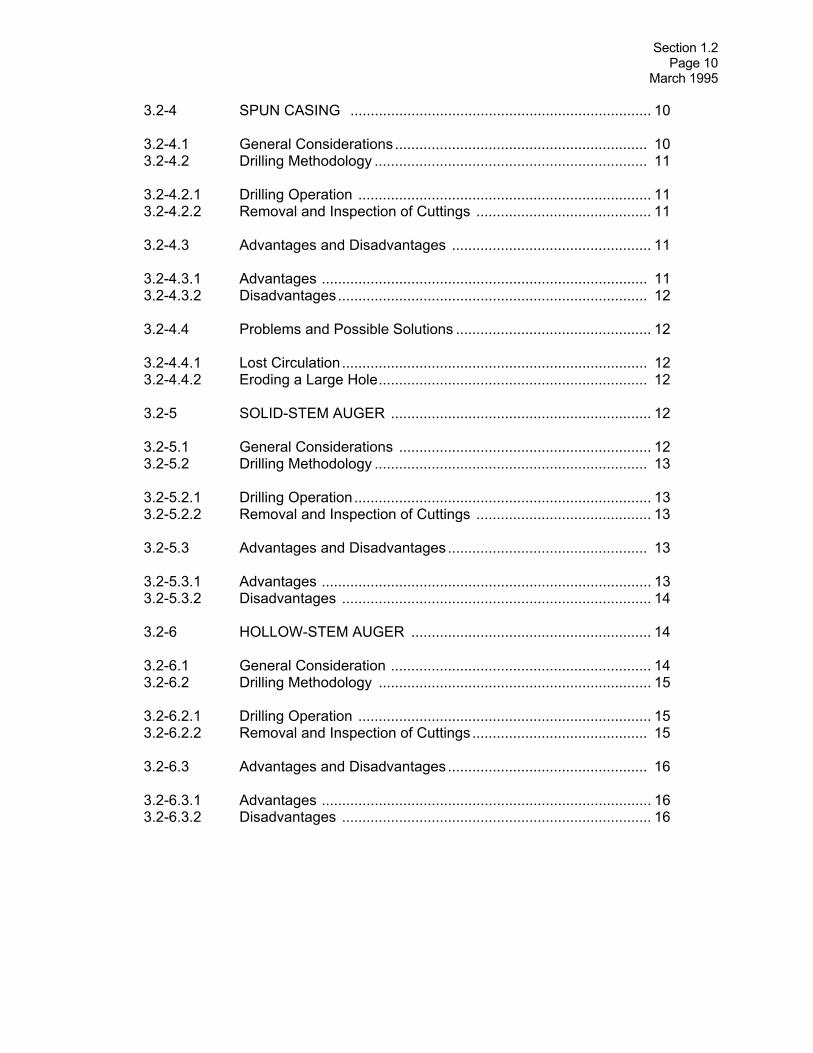
3.2-4 SPUN CASING .......................................................................... 10 3.2-4.1 General Considerations.............................................................. 10 3.2-4.2 Drilling Methodology ................................................................... 11 3.2-4.2.1 Drilling Operation ........................................................................ 11 3.2-4.2.2 Removal and Inspection of Cuttings ........................................... 11 3.2-4.3 Advantages and Disadvantages ................................................. 11 3.2-4.3.1 Advantages ................................................................................ 11 3.2-4.3.2 Disadvantages............................................................................ 12 3.2-4.4 Problems and Possible Solutions ................................................ 12 3.2-4.4.1 Lost Circulation........................................................................... 12 3.2-4.4.2 Eroding a Large Hole.................................................................. 12 3.2-5 SOLID-STEM AUGER ................................................................ 12 3.2-5.1 General Considerations .............................................................. 12 3.2-5.2 Drilling Methodology ................................................................... 13 3.2-5.2.1 Drilling Operation......................................................................... 13 3.2-5.2.2 Removal and Inspection of Cuttings ........................................... 13 3.2-5.3 Advantages and Disadvantages................................................. 13 3.2-5.3.1 Advantages ................................................................................. 13 3.2-5.3.2 Disadvantages ............................................................................ 14 3.2-6 HOLLOW-STEM AUGER ........................................................... 14 3.2-6.1 General Consideration ................................................................ 14 3.2-6.2 Drilling Methodology ................................................................... 15 3.2-6.2.1 Drilling Operation ........................................................................ 15 3.2-6.2.2 Removal and Inspection of Cuttings ........................................... 15 3.2-6.3 Advantages and Disadvantages................................................. 16 3.2-6.3.1 Advantages ................................................................................. 16 3.2-6.3.2 Disadvantages ............................................................................ 16

Section 1.2 Page 11 March 1995
3.2-6.4 Problems and Possible Solutions ................................................ 16 3.2-6.4.1 Sand or Silt Flowing Up Inside the Auger; "Running Sands" ........................................................................................ 16 3.2-6.4.2 Health and Safety Problems ....................................................... 17 3.2-7 MUD ROTARY ............................................................................ 17 3.2-7.1 General Consideration................................................................. 17 3.2-7.2 Drilling Methodology ................................................................... 18 3.2-7.2.1 Drilling Operation......................................................................... 18 3.2-7.2.2 Removal and Inspection of Cuttings ........................................... 18 3.2-7.3 Advantages and Disadvantages ................................................. 18 3.2-7.3.1 Advantages ................................................................................. 18 3.2-7.3.2 Disadvantages............................................................................. 18 3.2-7.4 Problems and Possible Solutions ................................................ 19 3.2-7.4.1 Lost Circulation............................................................................ 19 3.2-7.4.2 Crooked Holes............................................................................. 19 3.2-7.4.3 Stuck Bits and Rods .................................................................... 19 3.2-8 AIR ROTARY/AIR HAMMER....................................................... 20 3.2-8.1 Drilling Methodology ................................................................... 20 3.2-8.1.1 Drilling Operation........................................................................ 20 3.2-8.1.2 Removal and Inspection of Cuttings ........................................... 20 3.2-8.2 Advantages and Disadvantages ................................................. 20 3.2-8.2.1 Advantages.................................................................................. 20 3.2-8.2.2 Disadvantages............................................................................. 21 3.2-8.3 Problems and Possible Solutions ............................................... 21 3.2-8.3.1 Contaminated Air Injected into Boring ......................................... 21 3.2-8.3.2 Air Emission Hazards ................................................................. 21

Section 1.2 Page 12 March 1995
3.2-9 ODEX SYSTEM......................................................................... 22 3.2-9.1 General Considerations .............................................................. 22 3.2-9.2 Drilling Methodology ................................................................... 22 3.2-9.3 Advantages and Disadvantages ................................................. 22 3.2-9.3.1 Advantages ................................................................................. 22 3.2-9.3.2 Disadvantages............................................................................. 23 3.2-10 DRILLING FLUIDS ...................................................................... 23 3.2-10.1 Functions of Drilling Fluids .......................................................... 23 3.2-10.2 Factors Affecting Performance. ................................................... 23 3.2-10.3 Types of Drilling Fluids ............................................................... 24 3.2-10.3.1 Water ......................................................................................... 24 3.2-10.3.2 Drilling Mud ................................................................................ 25 REFERENCES.................................................................................................... 26 ADDITIONAL REFERENCES ............................................................................ 26

Section 1.2 Page 13 March 1995
SECTION 3.2 DRILLING TECHNIQUES
LIST OF FIGURES Figure Title Page No. 3.2-1 Illustration of Cable Tool Drill Rig ............................................... 29 3.2-2 Cable Rig Drilling Tools ............................................................... 30 3.2-3 Schematic of Drive and Wash Drilling Method ........................... 31 3.2-4 Schematic of Spun Casing Drilling Method ................................. 32 3.2-5 Schematic of Solid-stem Auger Drilling Method ......................... 33 3.2-6 Components of Hollow-stem Auger ............................................ 34 3.2-7 Detail of Lead Hollow-stem Auger ............................................... 35 3.2-8 Schematic of Rotary Drill Rig ...................................................... 36 3.2-9 Drill String for Mud Rotary Drilling ............................................... 37 3.2-10 Schematic of Mud Rotary Drilling Method .................................. 37 3.2-11 Schematic of Air Rotary Drilling Method..................................... 39 3.2-12 Schematic of Air Circulation........................................................ 40 3.2-13 Schematic of ODEX Bit.............................................................. 41 3.2-14 Major Elements of ODEX Drilling System.................................... 42
Section 1.2 Page 14 March 1995
SECTION 3.2 DRILLING TECHNIQUES
LIST OF TABLES
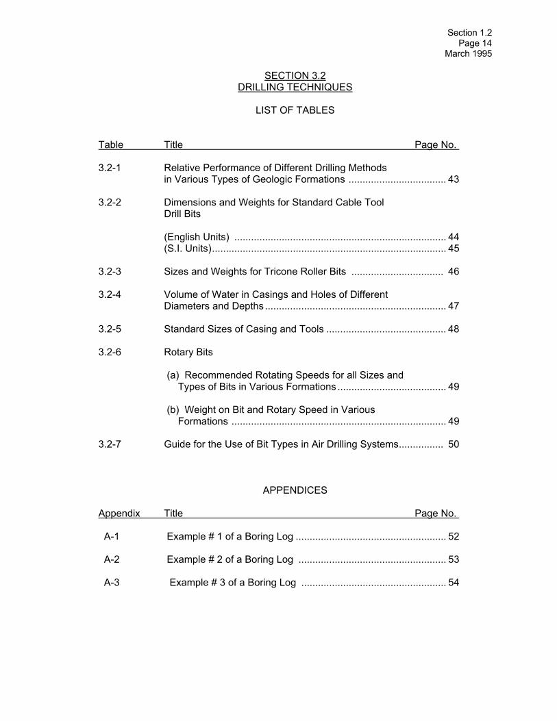
Table Title Page No. 3.2-1 Relative Performance of Different Drilling Methods in Various Types of Geologic Formations ................................... 43 3.2-2 Dimensions and Weights for Standard Cable Tool Drill Bits (English Units) ............................................................................ 44 (S.I. Units).................................................................................... 45 3.2-3 Sizes and Weights for Tricone Roller Bits ................................. 46 3.2-4 Volume of Water in Casings and Holes of Different Diameters and Depths ................................................................. 47 3.2-5 Standard Sizes of Casing and Tools ........................................... 48 3.2-6 Rotary Bits (a) Recommended Rotating Speeds for all Sizes and Types of Bits in Various Formations ....................................... 49 (b) Weight on Bit and Rotary Speed in Various Formations ............................................................................. 49 3.2-7 Guide for the Use of Bit Types in Air Drilling Systems................ 50
APPENDICES Appendix Title Page No. A-1 Example # 1 of a Boring Log ...................................................... 52 A-2 Example # 2 of a Boring Log ..................................................... 53 A-3 Example # 3 of a Boring Log .................................................... 54

Section 1.2 Page 15 March 1995
SECTION 3.3 BORINGS IN CONTAMINATED AREAS
TABLE OF CONTENTS
Section Title Page No. 3.3-1 PURPOSE .................................................................................... 1 3.3-2 RECOMMENDED DRILLING METHODS ................................... 2 3.3-2.1 Telescoping Casing ...................................................................... 2 3.3-2.2 Hollow-stem Auger/Flush-joint Casing .......................................... 3 3.3-3 DISPOSAL OF DRILLING SPOILS .............................................. 4 3.3-4 DECONTAMINATION OF EQUIPMENT ...................................... 4 3.3-4.1 Cleaning the Drill Rig .................................................................... 5 REFERENCES .................................................................................................... 6
LIST OF FIGURES Figure Title Page No. 3.3-1 Telescoped Casing Method ........................................................ 8 3.3-2 Monitoring Well Installed with Telescoped Casing Method ............................................................................ 9 3.3-3 Contaminated Borings - Drilling with Hollow-stem Augers/Flush-joint Casing ......................................................... 10
Section 1.2 Page 16 March 1995
SECTION 3.4 IN-SITU SAMPLING OF SOIL
TABLE OF CONTENTS
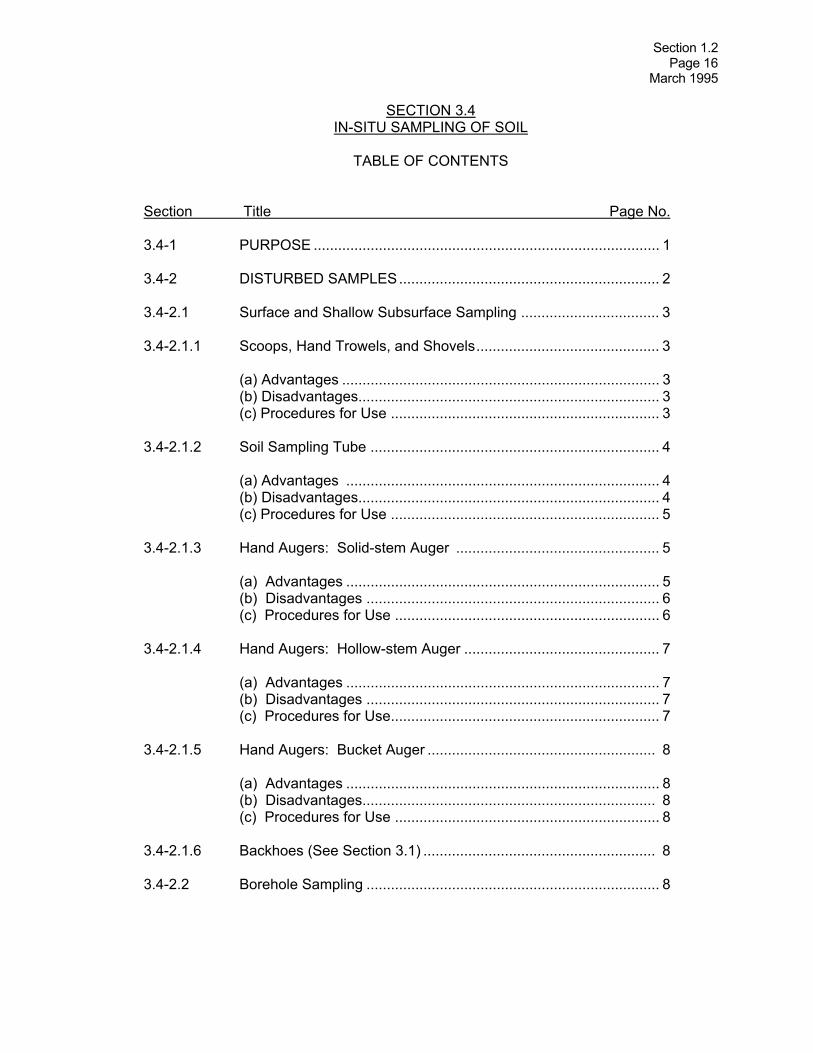
Section Title Page No. 3.4-1 PURPOSE ..................................................................................... 1 3.4-2 DISTURBED SAMPLES................................................................ 2 3.4-2.1 Surface and Shallow Subsurface Sampling .................................. 3 3.4-2.1.1 Scoops, Hand Trowels, and Shovels............................................. 3 (a) Advantages .............................................................................. 3 (b) Disadvantages.......................................................................... 3 (c) Procedures for Use .................................................................. 3 3.4-2.1.2 Soil Sampling Tube ....................................................................... 4 (a) Advantages ............................................................................. 4 (b) Disadvantages.......................................................................... 4 (c) Procedures for Use .................................................................. 5 3.4-2.1.3 Hand Augers: Solid-stem Auger .................................................. 5 (a) Advantages ............................................................................. 5 (b) Disadvantages ........................................................................ 6 (c) Procedures for Use ................................................................. 6 3.4-2.1.4 Hand Augers: Hollow-stem Auger ................................................ 7 (a) Advantages ............................................................................. 7 (b) Disadvantages ........................................................................ 7 (c) Procedures for Use.................................................................. 7 3.4-2.1.5 Hand Augers: Bucket Auger ........................................................ 8 (a) Advantages ............................................................................. 8 (b) Disadvantages........................................................................ 8 (c) Procedures for Use ................................................................. 8 3.4-2.1.6 Backhoes (See Section 3.1) ......................................................... 8 3.4-2.2 Borehole Sampling ........................................................................ 8

Section 1.2 Page 17 March 1995
SECTION 3.4 IN-SITU SAMPLING OF SOIL
TABLE OF CONTENTS
(continued)
Section Title Page No. 3.4-2.2.1 Driven Split-spoon and Split-tube Samplers ................................. 9 (a) Advantages .............................................................................. 9 (b) Disadvantages ......................................................................... 9 (c) Sampling Intervals .................................................................. 10 (1) Continuous Sampling ............................................................ 10 (2) 5-Foot Intervals .................................................................... 10 (d) Procedures for Use ............................................................... 11 3.4-2.2.2 Auger-advanced Split-tube Sampler........................................... 12 (a) Advantages ........................................................................... 12 (b) Disadvantages ...................................................................... 12 (c) Procedures for Use ............................................................... 12 3.4-2.2.3 Sampling Borehole Cuttings ........................................................ 13 (a) Wash Sampling ...................................................................... 13 (b) Auger Cuttings....................................................................... .13 3.4-3 STORAGE OF DISTURBED SOIL SAMPLES ............................ 14 3.4-3.1 Containers for Soil Samples ...................................................... 14 3.4-3.2 Data for Labels and Field Book .................................................. 14 3.4-3.3 Storage and Shipment ................................................................ 15 3.4-4 REPRESENTATIVE "UNDISTURBED" SOIL SAMPLES ........... 15 3.4-4.1 Thin-wall Tube Sampler............................................................... 15 3.4-4.1.1 Open-drive Sampler..................................................................... 16 (a) Advantages ......................................................................... 16 (b) Disadvantages ...................................................................... 17 (c) Procedures for Use (See Section 3.4-4.1.4) .......................... 17

Section 1.2 Page 18 March 1995
SECTION 3.4 IN-SITU SAMPLING OF SOIL
TABLE OF CONTENTS
(continued) Section Title Page No. 3.4-4.1.2 Stationary Fixed Piston (SFP) Sampler ....................................... 17 (a) Advantages ......................................................................... 17 (b) Disadvantages ..................................................................... 17 (c) Procedures for Use (See Section 3.4-4.1.4)......................... 17 3.4-4.1.3 Hydraulic (Osterberg) Piston Sampler ........................................ 18 (a) Advantages .......................................................................... 18 (b) Disadvantages...................................................................... 18 (c) Procedures for Use (See Section 3.4-4.1.4).......................... 18 3.4-4.1.4 Procedures Used to Collect Thin-wall Tube Samples ................. 18 3.4-4.2 Rotary Core Soil Samples .......................................................... 20 3.4-4.2.1 Denison Sampler ......................................................................... 20 3.4-4.2.2 Pitcher Sampler ........................................................................... 21 3.4-4.3 Block Samples............................................................................. 22 3.4-5 PROBLEMS AND SUGGESTED SOLUTIONS.......................... 22 3.4-5.1 Inadequate Sample Recovery .................................................... 22 3.4-5.1.1 Residual Cuttings......................................................................... 22 3.4-5.1.2 Loss of Sample ........................................................................... 23 3.4-5.1.3 Blockage of Sampler.................................................................... 23 3.4-5.1.4 Densification of Frictional Resistance......................................... 23 3.4-5.2 Sample Disturbance .................................................................... 23 REFERENCES ................................................................................................... 25

Section 1.2 Page 19 March 1995
SECTION 3.4
IN-SITU SAMPLING OF SOIL
LIST OF FIGURES Figure Title Page No. 3.4-1 Schematic of Surface Soil Sampling............................................ 27 3.4-2 Soil Sampling Tube ..................................................................... 28 3.4-3 Hand Auger.................................................................................. 29 3.4-4 Split-spoon Sampler .................................................................... 30 3.4-5 Schematic of Split-spoon Soil Sample Logging .......................... 31 3.4-6 Auger-advanced Split-spoon Sampler ......................................... 32 3.4-7 Split-spoon Samples Recording Lithologic Changes .................. 33 3.4-8 Split-spoon Samples at 6 in. Intervals ........................................ 34 3.4-9 Thin-wall Sampling Tube ............................................................. 35 3.4-10 Stationary Fixed Piston Sampler ................................................. 36 3.4-11 Hydraulic (Osterberg) Piston Sampler Operation ....................... 37 3.4-12 Denison Sampler ........................................................................ 38 3.4-13 Pitcher Sampler ........................................................................... 39
LIST OF TABLES Table Title Page No. 3.4-1 Standard Dimensions for Thin-wall Tubing ................................ 40

Section 1.2 Page 20 March 1995
SECTION 3.5
SOIL CLASSIFICATION
TABLE OF CONTENTS Section Title Page No. 3.5-1 PURPOSE .................................................................................... 1 3.5-2 CLASSIFICATION SYSTEMS....................................................... 1 3.5-3 METHODOLOGY ......................................................................... 2 3.5-3.1 Color ............................................................................................. 2 3.5-3.2 Gradation: Coarse-grained Soils Versus Fine-grained Soils.......................................................................... 3 3.5-3.2.1 Coarse-grained Soil Identification Procedures ............................. 3 3.5-3.2.2 Fine-grained Soil Identification Procedures .................................. 3 (a) Dilatancy.................................................................................. 4 (b) Dry Strength ............................................................................ 4 (c) Stiffness/Plasticity.................................................................... 5 (d) Soil Thread Test ...................................................................... 5 (e) Ball Thread Test ...................................................................... 6 (f) Test Tube Test ........................................................................ 6 3.5-3.3 Gradation Designation................................................................... 6 3.5-3.4 Density/Consistency ...................................................................... 7 3.5-3.4.1 Relative Density: Coarse-grained Soils ........................................ 7 3.5-3.4.2 Consistency: Fine-grained Soils .................................................. 7 3.5-3.5 Particle Angularity.......................................................................... 7 3.5-3.6 Moisture Content .......................................................................... 8 3.5-3.7 Structure ...................................................................................... 8 3.5-3.8 Reaction to Hydrochloric Acid........................................................ 9 3.5-3.9 Geologic Name........................................................................... 10 3.5-3.10 Unified Soil Classification (USC) Designation ............................ 10 3.5-3.11 Special Conditions or Notes ....................................................... 11 REFERENCES.................................................................................................... 12

Section 1.2 Page 21 March 1995
SECTION 3.5 SOIL CLASSIFICATION
LIST OF FIGURES
Figure Title Page No. 3.5-1 Soil Classification Systems Based on Grain Size........................ 14 3.5-2 Soil Classification Flow Chart ...................................................... 15 3.5-3 Plasticity Chart for Laboratory Classification of Fine-grained Soils ....................................................................... 16 3.5-4 Gradation Designation................................................................. 17 3.5-5 Particle Angularity........................................................................ 18 3.5-6 Unified Soil Classification System .............................................. 19
LIST OF TABLES Table Title Page No. 3.5-1 Particle Size Identification Based on Unified Soil Classification System................................................................... 20 3.5.2 Burmister System Descriptors Suitable for Estimating the Distribution of Gravel-, Sand-, and Silt-Size Particles....................................................................................... 21 3.5-3 Criteria for Describing Consistency Based on Field Tests ................................................................................... 22

Section 1.2 Page 22 March 1995
SECTION 3.6
IN-SITU SAMPLING OF ROCK
TABLE OF CONTENTS Section Title Page No. 3.6-1 PURPOSE ..................................................................................... 1 3.6-2 SURFACE ROCK SAMPLING....................................................... 1 3.6-2.1 Methodology .................................................................................. 1 3.6-2.2 Procedure ...................................................................................... 2 3.6-3 ROCK CORE SAMPLING ............................................................. 2 3.6-3.1 Sampling Equipment...................................................................... 2 3.6-3.1.1 Double-tube Core Barrel................................................................ 3 3.6-3.1.2 Triple-tube Core Barrel .................................................................. 5 3.6-3.1.3 Wireline Core Barrel ..................................................................... 6 3.6-3.1.4 Oriented Core Equipment .............................................................. 7 (a) Orienting Core Barrel ............................................................. 7 (b) BHP Orienting Core Barrel ..................................................... 7 (c) Christensen-Hugel Orienting Core Barrel ............................... 7 3.6-3.2 Rock Coring Procedure ................................................................. 7 3.6-3.3 Sample Handling and Storage....................................................... 9 3.6-3.4 Logging Rock Cores ...................................................................... 9 3.6-3.4.1 Geologic Core Log...................................................................... 10 3.6-3.4.2 Logging Procedure ...................................................................... 10 3.6-3.4.3 Rock Quality Determination (RQD)............................................. 10 3.6-3.4.4 Documentation............................................................................. 11 3.6-3.4.5 Logging Equipment...................................................................... 12 3.6-3.5 Other Specialty Core Barrels ...................................................... 12 3.6-3.5.1 Calyx or Shot-core Barrel ............................................................ 12 3.6-3.5.2 Steel-tooth Cutter Barrel .............................................................. 13 3.6-3.5.3 Percussion Core Barrel ............................................................... 13 3.6-3.5.4 Single-tube Core Barrel ............................................................... 13 REFERENCES.................................................................................................... 14

Section 1.2 Page 23 March 1995
SECTION 3.6 IN-SITU SAMPLING OF ROCK
LIST OF FIGURES
Figure Title Page No. 3.6-1 Different Types of Core Bits......................................................... 16 3.6-2 Single- and Double-tube Core Barrels......................................... 17 3.6-3 Wireline Core Barrel .................................................................... 18 3.6-4 Core Box...................................................................................... 19 3.6-5 Example # 1 of Borehole Core Log.............................................. 20 3.6-6 Example # 2 of Borehole Core Log.............................................. 21
LIST OF TABLES
Table Title Page No. 3.6-1 Standard Sizes of Diamond Core Bits and Wireline .................... 22

Section 1.2 Page 24 March 1995
SECTION 3.7 ROCK CLASSIFICATION
TABLE OF CONTENTS
Section Title Page No. 3.7-1 PURPOSE ..................................................................................... 1 3.7-2 METHODOLOGY .......................................................................... 1 3.7-2.1 Rock Type..................................................................................... 1 3.7-2.1.1 Hardness ...................................................................................... 2 3.7-2.1.2 Color. ............................................................................................ 2 3.7-2.1.3 Grain Size...................................................................................... 3 (a) Igneous, Metamorphic, and Crystalline Sedimentary Rock ......................................................................... 3 (b) Clastic Sedimentary Rock ....................................................... 3 3.7-2.1.4 Texture .......................................................................................... 3 (a) Igneous .................................................................................... 4 (b) Sedimentary: Clastic Category............................................... 4 (c) Sedimentary: Chrystalline Category ...................................... 4 (d) Metamorphic ........................................................................... 4 3.7-2.1.5 Mineral Content ........................................................................... 5 3.7-2.1.6 Identifying Rock Types .................................................................. 5 3.7-2.2 Description of Weathering and Structural Features...................... 5 3.7-2.2.1 Weathering ................................................................................... 6 3.7-2.2.2 Structure ........................................................................................ 6 (a) Discontinuities ......................................................................... 7 (1) Types of Discontinuities .................................................... 7 (2) Spacing .............................................................................. 7 (3) Tightness............................................................................ 8 (4) Attitude ............................................................................... 8 (5) Regularity .......................................................................... 8 (6) Consistency ....................................................................... 8 (7) Filling .................................................................................. 8 (b) Vertical Spacing of Layering..................................................... 8 (c) Descriptions Specific to Rock Cores ........................................ 9 (1) Rock Core Discontinuity .................................................... 9 (2) Rock Quality Designation (RQD)...................................... 9
Section 1.2 Page 25 March 1995
SECTION 3.7 ROCK CLASSIFICATION
TABLE OF CONTENTS
(continued) Section Title Page No. REFERENCES.................................................................................................... 11 ADDITIONAL REFERENCES ............................................................................ 11
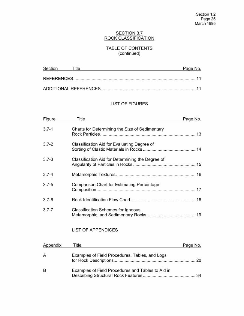
LIST OF FIGURES Figure Title Page No. 3.7-1 Charts for Determining the Size of Sedimentary Rock Particles.............................................................................. 13 3.7-2 Classification Aid for Evaluating Degree of Sorting of Clastic Materials in Rocks ........................................... 14 3.7-3 Classification Aid for Determining the Degree of Angularity of Particles in Rocks ................................................... 15 3.7-4 Metamorphic Textures ................................................................ 16 3.7-5 Comparison Chart for Estimating Percentage Composition................................................................................. 17 3.7-6 Rock Identification Flow Chart .................................................... 18 3.7-7 Classification Schemes for Igneous, Metamorphic, and Sedimentary Rocks........................................ 19 LIST OF APPENDICES Appendix Title Page No. A Examples of Field Procedures, Tables, and Logs for Rock Descriptions................................................................... 20 B Examples of Field Procedures and Tables to Aid in Describing Structural Rock Features ........................................... 34

Section 1.2 Page 26 March 1995
SECTION 3.8 LABORATORY TESTS FOR SOIL
TABLE OF CONTENTS
Section Title Page No. 3.8-0 INTRODUCTION .......................................................................... 1 3.8-1 GRAIN SIZE ANALYSIS................................................................ 2 3.8-1.1 Standard Test Methods ................................................................. 2 3.8-1.2 Significance and Use.................................................................... 2 3.8-1.3 Physical Parameters Obtained ...................................................... 2 3.8-1.4 Field Sampling Methods, Sample Size and Preservation.............. 3 3.8-2 SPECIFIC GRAVITY OF SOIL ..................................................... 3 3.8-2.1 Standard Test Method .................................................................. 3 3.8-2.2 Significance and Use .................................................................... 3 3.8-2.3 Physical Parameters Obtained ..................................................... 3 3.8-2.4 Field Sampling Methods, Sample Size, and Preservation............. 3 3.8-2.5 Special Considerations ................................................................. 3 3.8-3 ATTERBERG LIMITS4 3.8-3.1 Standard Test Methods ................................................................. 4 3.8-3.2 Significance and Use..................................................................... 4 3.8-3.3 Physical Parameters Obtained ..................................................... 4 3.8-3.4 Field Sampling Methods, Sample Size, and Preservation............. 4 3.8-3.5 Special Considerations ................................................................. 4 3.8-4 MOISTURE CONTENT ................................................................. 5 3.8-4.1 Standard Test Method ................................................................... 5 3.8-4.2 Significance and Use..................................................................... 5 3.8-4.3 Physical Parameters Obtained ...................................................... 5 3.8-4.4 Field Sampling Methods, Sample Size, and Preservation............. 5 3.8-4.5 Special Considerations ................................................................. 6 3.8-5 ORGANIC CONTENT................................................................... .6 3.8-5.1 Standard Test Method .................................................................. .6 3.8-5.2 Significance and Use..................................................................... 6 3.8-5.3 Physical Parameters Obtained ...................................................... 6 3.8-5.4 Field Sampling Methods, Sample Size, and Preservation............. 6

Section 1.2 Page 27 March 1995
SECTION 3.8
LABORATORY TESTS FOR SOIL AND ROCK (continued)
TABLE OF CONTENTS
Section Title Page No. 3.8-6 MOISTURE-DENSITY RELATIONSHIPS OF SOILS (LABORATORY COMPACTION TEST) ....................................... 6 3.8-6.1 Standard Test Methods ................................................................. 6 3.8-6.2 Significance and Use.................................................................... 7 3.8-6.3 Physical Parameters Obtained ...................................................... 7 3.8-6.4 Field Sampling Methods, Sample Size, and Preservation............. 7 3.8-7 STRENGTH TESTING OF SOILS................................................. 7 3.8-7.1 Standard Test Methods ................................................................. 7 3.8-7.2 Significance and Use..................................................................... 8 3.8-7.3 Physical Parameters Obtained ..................................................... 8 3.8-7.4 Field Sampling Methods, Sample Size, and Preservation ............ 8 3.8-8 CONSOLIDATION TEST .............................................................. 9 3.8-8.1 Standard Test Method .................................................................. 9 3.8-8.2 Significance and Use.................................................................... 9 3.8-8.3 Physical Parameters Obtained ..................................................... 9 3.8-8.4 Field Sampling Methods, Sample Size, and Preservation.......... 10 3.8-9 PERMEABILITY OF SOILS......................................................... 10 3.8-9.1 Standard Test Methods ............................................................... 10 3.8-9.2 Significance and Use .................................................................. 10 3.8-9.3 Physical Parameters Obtained ................................................... 10 3.8-9.4 Field Sampling Methods, Sample Size, and Preservation.......... 11 3.8-9.5 Special Considerations ............................................................... 11

Section 1.2 Page 28 March 1995
SECTION 3.8
LABORATORY TESTS FOR SOIL AND ROCK
LIST OF TABLES Table Title Page No. 3.8-1 Sample Size Needed to Analyze for Various Maximum Particle Sizes in Test for Grain Size Analysis ............................. 12 3.8-2 Mass of Moist Specimen Recommended for Different Sieve Sizes for Analysis for Moisture Content............................. 13

Section 1.2 Page 29 March 1995
SECTION 3.9 PLUGGING BOREHOLES
TABLE OF CONTENTS
Section Title Page No. 3.9-1 PURPOSE ..................................................................................... 1 3.9-2 METHODOLOGY .......................................................................... 1 3.9-2.1 Plugging Material ........................................................................... 1 3.9-2.2 Installation Techniques.................................................................. 2 3.9-2.2.1 Mud Rotary Boreholes ................................................................... 2 3.9-2.2.2 Cased Boreholes ........................................................................... 2 3.9-2.2.3 Auger Boreholes........................................................................... 2

Section 1.2 Page 30 March 1995
SECTION 4.1 MONITORING WELL NETWORK DESIGN
TABLE OF CONTENTS
Section Title Page No. 4.1-1 PURPOSE .................................................................................... 1 4.1-2 DESIGN CONSIDERATIONS ....................................................... 2 4.1-2.1 Objective(s) of the Investigation ................................................... 2 4.1-2.1.1 Investigations at Uncontaminated Sites........................................ 2 4.1-2.1.2 Investigations at Contaminated Sites ............................................ 2 4.1-2.2 Collecting Representative Data ..................................................... 2 4.1-2.3 Maximizing the Information with a Limited Number of Wells .............................................................................................. 3 4.1-2.4 Incorporating Flexibility in the Design ............................................ 3 4.1-2.5 Budget Considerations .................................................................. 4 4.1-3 DEFINING THE PROBLEM........................................................... 4 4.1-3.1 Understanding the Physical Setting............................................... 4 4.1-3.1.1 Geology ......................................................................................... 4 4.1-3.1.2 Hydrogeology ................................................................................ 5 4.1-3.1.3 Existing Surface and Subsurface Structures ................................. 5 4.1-3.1.4 Conceptual Model.......................................................................... 5 4.1-3.2 Understanding the Physical and Chemical Characteristics of Contaminants................................................... 5 4.1-3.2.1 Aqueous Dissolved Phase Liquids (ADPLs).................................. 6 4.1-3.2.2 Non-aqueous Phase Liquids (NAPLs) ........................................... 6 (a) "Floaters" ................................................................................. 6 (b) "Sinkers"................................................................................... 6 4.1-3.3 Preliminary Exposure Characterization ........................................ 7 4.1-4 METHODOLOGY .......................................................................... 7 4.1-4.1 Compilation of Available Background Data ................................... 7 4.1-4.2 Well Locations ............................................................................... 8

Section 1.2 Page 31 March 1995
SECTION 4.1 MONITORING WELL NETWORK DESIGN
TABLE OF CONTENTS
(continued) Section Title Page No. 4.1-4.2.1 Horizontal Spacing......................................................................... 8 (a) Upgradient Wells ..................................................................... 9 (b) Downgradient Wells ................................................................ 9 4.1-4.2.2 Vertical Spacing........................................................................... 10 4.1-4.3 Selection of Well Type................................................................. 10 4.1-4.3.1 Piezometers ................................................................................ 11 4.1-4.3.2 Observation Wells........................................................................ 11 4.1-4.3.3 Monitoring Wells .......................................................................... 12 (a) Single Standpipe Wells ......................................................... 12 (1) Depth-specific Wells.............................................................. 12 (2) Depth-integrated Wells.......................................................... 12 (b) Multi-level Wells ..................................................................... 13
(1) Stacked Wells (Well Nest) .................................................... 13 (2) Well Cluster ........................................................................... 14 (3) Specialized Well Systems: Waterloo, Westbay,
and Barcad ................................................................................. .14 REFERENCES ................................................................................................... 16 ADDITIONAL REFERENCES ............................................................................. 16
Section 1.2 Page 32 March 1995
SECTION 4.1 MONITERING WELL NETWORK DESIGN
LIST OF FIGURES
Figure Title Page No. 4.1-1 Geologic Cross-section................................................................ 18 4.1-2 Ground Water Contour Map ........................................................ 18 4.1-3 Sketch of Floating Contaminant................................................... 19 4.1-4 Illustration of Sinking Contaminant in a Porous Material......................................................................... 20 4.1-5 Illustration of Sinking Contaminant in Fractured Bedrock ....................................................................... 21 4.1-6 Basic Well Types ......................................................................... 22 4.1-7 Waterloo Multilevel Monitoring Well Detail .................................. 23 4.1-8 Westbay Multilevel Well .............................................................. 24 4.1-9 Typical Barcad Installation.......................................................... 25 4.1-10 Detail of a Barcad Sampler.......................................................... 26

Section 1.2 Page 33 March 1995
SECTION 4.2
SELECTION OF WELL CONSTRUCTION MATERIALS
TABLE OF CONTENTS Section Title Page No. 4.2-1 PURPOSE ..................................................................................... 1 4.2-2 CASING MATERIALS .............................................................................. 2 4.2-2.1 Composition................................................................................... 2 4.2-2.1.1 Polyvinyl Chloride ......................................................................... 2 4.2-2.1.2 Stainless Steel ............................................................................... 3 4.2-2.1.3 Teflon............................................................................................. 4 4.2-2.2 Size .............................................................................................. 4 4.2-3 WELL SCREEN SELECTION........................................................ 5 4.2-3.1 Slot Size......................................................................................... 5 4.2-3.2 Style............................................................................................... 5 4.2-3.2.1 Slotted Pipe .................................................................................. 6 4.2-3.2.2 Wire-wound, Continuous Slot Pipe............................................... 6 4.2-3.3 Sediment Sump ............................................................................. 7 4.2-4 FILTER PACK................................................................................ 7 4.2-4.1 Washed Sand ................................................................................ 8 4.2-4.2 Uniformly-graded Silica Sand ....................................................... 8 4.2-5 SEALS ........................................................................................... 9 4.2-5.1 Surface Seal (aprons).................................................................... 9 4.2-5.2 Divider Seal .................................................................................. 9 4.2-5.3 Bedrock Seal ............................................................................. 10 4.2-5.4 Annular Seal ................................................................................ 10 4.2-6 SEALING MATERIALS................................................................ 10 4.2-6.1 Solid Well Sealants...................................................................... 10 4.2-6.1.1 Bentonite Pellets.......................................................................... 10 4.2-6.1.2 Coarse-grade Bentonite Chips ................................................... 11 4.2-6.2 Grout Seals.................................................................................. 11

Section 1.2 Page 34 March 1995
SECTION 4.2 SELECTION OF WELL CONSTRUCTION MATERIALS
TABLE OF CONTENTS
(continued) Section Title Page No. 4.2-6.2.1 Cement-based Grouts ................................................................. 11 (a) Neat Cement ........................................................................ 12 (b) Neat Cement with Bentonite.................................................. 12 (c) Concrete................................................................................ 12 (d) Cement Additives .................................................................. 13 4.2-6.2.2 Bentonite-based Grouts.............................................................. 13 (a) Heavy Bentonite Grout ......................................................... 13 (b) High-solids Bentonite Grout ................................................. 13 (c) Granular Bentonite Slurries .................................................. 13 4.2-7 PROTECTIVE CASINGS............................................................ 14 4.2-7.1 Above-ground Protective Casing ................................................ 14 4.2-7.2 Flush-mount or Road-box Casing ............................................... 14 REFERENCES .................................................................................................. 16 ADDITIONAL REFERENCES ............................................................................. 17

Section 1.2 Page 35 March 1995
SECTION 4.2 SELECTION OF WELL CONSTRUCTION MATERIALS
LIST OF FIGURES Figure Title Page No. 4.2-1 Well Component Diagram........................................................... 20 4.2-2 Types of Well Screen Slots ......................................................... 21 4.2-3 Diagram of a Sediment Sump..................................................... 22 4.2-4 Above-ground Protective Casing ................................................ 23 4.2-5 Flush-mount Road-box ............................................................... 24 4.2-6 Manhole-type Road-box .............................................................. 25 4.2-7 Protective Posts Around a Monitoring Well ................................. 26
LIST OF TABLES Table Title Page No. 4.2-1 Basic Well Casing and Screen Material Composition................................................................................. 27 4.2-2 Volume of Water in Casing or Hole ............................................. 28 4.2-3 Total Slot Area of Screen of Various Gauges in Square Inches per Foot .............................................................. 29 4.2-4 ASTM Cement Designations ...................................................... 30 4.2-5 Properties of Neat Cement Slurries ............................................ 31 4.2-6 Grout Properties - Advantages and Disadvantages .................... 32

Section 1.2 Page 36 March 1995
SECTION 4.3 WELL INSTALLATION PROCEDURES
TABLE OF CONTENTS
Section Title Page No. 4.3-1 PURPOSE .................................................................................... 1 4.3-2 COMPONENTS OF THE INSTALLATION .................................... 1 4.3-3 INSTALLATION OF SCREEN AND WELL CASING ..................... 2 4.3-3.1 Borehole Preparation..................................................................... 2 4.3-3.2 General Requirements................................................................... 3 4.3-3.3 Centralizers.................................................................................... 4 4.3-4 FILTER PACK................................................................................ 4 4.3-4.1 General Requirements................................................................... 4 4.3-4.2 Installation...................................................................................... 4 4.3-4.2.1 Tremie Method.............................................................................. 5 4.3-4.2.2 Freefall and Tamp Method............................................................. 5 4.3-4.2.3 In-place Filter Pack....................................................................... 6 4.3-5 SEALS ........................................................................................... 6 4.3-5.1 General Requirements................................................................... 6 4.3-5.2 Types of Well Seals ...................................................................... 6 4.3-5.2.1 Divider Seals ................................................................................. 7 4.3-5.2.2 Annular Seals ............................................................................... 7 4.3-5.2.3 Surface Seals ............................................................................... 7 4.3-5.3 Installation...................................................................................... 7 4.3-5.3.1 Bentonite Pellets and Slurry .......................................................... 7 4.3-5.3.2 Grout Slurries................................................................................. 8 (a) Grout Pumps and Hoses......................................................... 8 (1) Positive Displacement Pumps................................................ 8 (2) Variable Displacement Pumps .............................................. 8 (3) Pump Hoses........................................................................... 9 (b) Grout Mixing............................................................................. 9 (1) Hand Mixing .......................................................................... 9 (2) Paddle Mixing ........................................................................ 9 (3) Recirculation Mixing ............................................................. 10 (4) Jet Mixing ............................................................................. 10 (c) Grout Placement Methods ..................................................... 10 (1) Tremie Method ................................................................... 10 (2) Surface Pour Method ..................................................... 10

Section 1.2 Page 37 March 1995
SECTION 4.3
WELL INSTALLATION PROCEDURES
TABLE OF CONTENTS (continued)
Section Title Page No. 4.3-6 PROTECTIVE CASING AND SURFACE SEAL ......................... 10 4.3-6.1 General Considerations............................................................... 10 4.3-6.1.1 Protective Casing Diameter ......................................................... 11 4.3-6.1.2 Depth of the Protective Casing.................................................... 11 4.3-6.1.3 Surface Seal ................................................................................ 11 4.3-6.2 Placement of the Protective Casing or Road Box....................... 11 4.3-6.3 Surface Seal ............................................................................... 12 4.3-6.4 Identification and Well Security.................................................... 12 4.3-7 PROBLEMS AND POSSIBLE SOLUTIONS ............................... 12 4.3-7.1 Artesian Conditions..................................................................... 12 4.3-7.2 Caving Conditions........................................................................ 13 4.3-7.3 Filter Pack Bridging Between Riser and Casing ......................... 13 4.3-7.4 Leakage through Road-box ......................................................... 13 4.3-7.5 Settlement of Protective Casing ................................................. 14 4.3-7.6 Heavy Traffic ............................................................................... 14 4.3-7.7 Winter Months ............................................................................. 14 REFERENCES.................................................................................................... 15 ADDITIONAL REFERENCES ............................................................................. 15

Section 1.2 Page 38 March 1995
SECTION 4.3 WELL INSTALLATION PROCEDURES
LIST OF FIGURES
Figure Title Page No. 4.3-1 Well Component Diagram (Overburden) ..................................... 19 4.3-2 Well Component Diagram (Screened in Bedrock) ...................... 20 4.3-3 Well Component Diagram (Open Hole in Bedrock) ..................... 21 4.3-4 Positive Displacement Pumps ..................................................... 22 4.3-5 Paddle Mixer................................................................................ 23 4.3-6 Diagram of a Recirculation Mixing Set-up ................................... 24 4.3-7 Jet Mixer Design ......................................................................... 25
LIST OF TABLES Table Title Page No. 4.3-1 Recommended Ratios for Most Common Grout Mixes .............. 26

Section 1.2 Page 39 March 1995
SECTION 4.4 AS-BUILT NOTES AND RECORDS
TABLE OF CONTENTS
Section Title Page No. 4.4-1 PURPOSE .................................................................................... 1 4.4-2 METHODOLOGY ......................................................................... 1 4.4-3 EXAMPLES OF EXISTING AND PROPOSED WATER WELL COMPLETION FORMS................................................................. 2 4.4-3.1 Well Completion Report Required by the Water Resources Commission................................................................. 2 4.4-3.2 Well Completion Report for Well Owner and Local Board of Health, Proposed by Division of Water Supply, Department of Environmental Protection......................... 3 4.4-3.3 Water Quality Report, Proposed by DEP Division of Water Supply................................................................ 4

Section 1.2 Page 40 March 1995
SECTION 4.4 AS-BUILT RECORDS AND NOTES
LIST OF FIGURES
Figure Title Page No. 4.4-1 Water Well Completion Report Available from Department of Environmental Management, Division of Water Resources....................................................................... 7 4.4-2 Example of an As-built Overburden Monitoring Well Form..................................................................... 8 4.4-3 Example of an As-built Bedrock Monitoring Well Form ...................................................................................... 9
APPENDICES
Appendix Title Page No. A Checklist and As-built Form for Monitoring Well Installation............................................................................ 11 B Review of Requirements for Registration and Well Completion Reports; Department of Environmental Management.................................................... 17

Section 1.2 Page 41 March 1995
SECTION 4.5 WELL DEVELOPMENT
TABLE OF CONTENTS
Section Title Page No. 4.5-1 PURPOSE ..................................................................................... 1 4.5-2 METHODOLOGY .......................................................................... 2 4.5-2.1 Over-pumping ............................................................................... 3 4.5-2.1.1 Advantages and Disadvantages................................................... 3
(a) Advantages .............................................................................. 3 (b) Disadvantages ......................................................................... 3 4.5-2.2 Backwashing (Rawhiding) ............................................................ 4 4.5-2.2.1 Advantages and Disadvantages.................................................... 4
Advantages.................................................................................... 4 Disadvantages............................................................................... 5
4.5-2.3 Mechanical Surging ...................................................................... 5 4.5-2.3.1 Advantages and Disadvantages ................................................... 5 (a) Advantages .............................................................................. 5 (b) Disadvantages.......................................................................... 6 4.5-2.4 Air-Surging and Air-lift Pumping ................................................... 6 4.5-2.4.1 Air-Surging..................................................................................... 6 4.5-2.4.2 Air-lift Pumping ............................................................................. 6 (a) Advantages and Disadvantages............................................... 7 (1) Advantages ............................................................................ 7 (2) Disadvantages......................................................................... 7 4.5-2.5 Water Jetting.................................................................................. 8 4.5-2.5.1 Advantages and Disadvantages................................................... 8 (a) Advantages .............................................................................. 8 (b) Disadvantages ......................................................................... 8 REFERENCES .................................................................................................... 9

Section 1.2 Page 42 March 1995
SECTION 4.5 WELL DEVELOPMENT
LIST OF FIGURES Figure Title Page No. 4.5-1 Operation of Surge Block System................................................ 11 4.5-2 Detail of Surge Block Equipment ................................................. 11 4.5-3 Air-lift Development System With Check Valve .......................... 12

Section 1.2 Page 43 March 1995
SECTION 4.6 DECOMMISSIONING OF MONITORING WELLS
TABLE OF CONTENTS
Section Title Page No. 4.6-1 PURPOSE ..................................................................................... 1 4.6-2 PRELIMINARY WORK TO BE PERFORMED BEFORE UNDERTAKING
WELL PLUGGING......................................................................... 2 4.6-2.1 Who can Perform Proper Well Decommissioning? ....................... 2 4.6-2.2 Location and Inspection................................................................. 2 4.62.3 Clearing the Well ........................................................................... 3 4.6-2.4 Casing Removal or Destruction ..................................................... 3 4.6-3 PLUGGING THE WELL................................................................. 4 4.6-3.1 Grouting Material ........................................................................... 4 4.6-3.2 Grout Placement............................................................................ 5 4.6-3.3 Calculations and Measurements ................................................... 6 4.6-4 FINAL SURFACE FINISH ............................................................. 6 4.6-5 RECORD OF DECOMMISSIONING ............................................. 6 4.6-6 PROHIBITIONS ............................................................................ 7
Section 1.2 Page 44 March 1995
SECTION 4.6 DECOMMISSIONING OF MONITORING WELLS
LIST OF FIGURES
Figure Title Page No. 4.6-1 Diagram of an Abandoned Overburden Well................................. 9 4.6-2 Diagram of an Abandoned Well Screened in Bedrock ....................................................................................... 10 4.6.3 Diagram of an Abandoned Well (Open Hole Well in Bedrock).................................................................................. 11 4.6-4 Minnesota Abandoned Well Report ............................................. 12 4.6-5 Iowa Abandoned Water Well Plugging Record........................... 13

Section 1.2 Page 45 March 1995
SECTION 5.1 WATER-LEVEL MEASUREMENTS
TABLE OF CONTENTS
Section Title Page No. 5.1-1 PURPOSE ................................................................................... 1 5.1-2 GENERAL CONSIDERATIONS ................................................... 1 5.1-2.1 Measuring Point . .......................................................................... 1 5.1-2.2 Records ........................................................................................ 1 5.1-3 INSTRUMENTS ........................................................................... 2 5.1-3.1 Weighted Tape (Plunker) ............................................................. 2 5.1-3.2 Chalked Tape. ............................................................................. 3 5.1-3.3 Electrical Tapes ............................................................................ 3 5.1-3.4 Transducer. ................................................................................... 4 5.1-3.5 Acoustic Well Probe ..................................................................... 5 5.1-3.6 Continuous Water-level Chart Recorder ...................................... 6 5.1-3.7 Interface Probes ........................................................................... 6 5.1-4 METHODOLOGY FOR MEASURING WATER LEVELS .............. 7 5.1-5 PROBLEMS AND POSSIBLE SOLUTIONS.................................. 9 5.1-5.1 Cross-contamination ..................................................................... 9 5.1-5.2 Water/Floating-fluids ..................................................................... 9 5.1-5.3 Flowing Artesian Conditions ......................................................... 9 5.1-5.4 Cyclic External Factors Affecting Water Levels ............................. 9 5.1-5.5 Non-Cyclic External Factors Affecting Water Levels................................................................................ 10 5.1-5.6 Dropping Something in a Well ..................................................... 10 ADDITIONAL REFERENCES ............................................................................. 11

Section 1.2 Page 46 March 1995
SECTION 5.1 WATER-LEVEL MEASUREMENTS
LIST OF FIGURES
Figure Title Page No. 5.1-1 Example of a Water-level Record Sheet ................................................ 13

Section 1.2 Page 47 March 1995
SECTION 5.2
IN-SITU HYDRAULIC CONDUCTIVITY TESTS
TABLE OF CONTENTS Section Title Page No. 5.2-1 PURPOSE ....................................................................................... 1 5.2-2 THEORY OF FLOW THROUGH SATURATED POROUS MEDIA .2 5.2-3 IN-SITU TESTS AND TEST PROCEDURES...................................4 5.2-3.1 Test Conditions..................................................................................4 5.2-3.1.1 Borehole Tests ..................................................................................4 5.2-3.1.2 Tests in Monitoring Wells ..................................................................4 5.2-3.2 Variable-head Tests ..........................................................................5 5.2-3.2.1 Falling-head Test ...............................................................................5 5.2-3.2.2 Rising-head Test ............................................................................. .5 5.2-3.2.3 Requisite Data ................................................................................. 5 5.2-3.2.4 General Test Methods .................................................................... .6 (a) Slug Injection or Withdrawal ........................................................6 (b) Equipment for Water-level Measurements ..................................7 (c) Duration of the Test..................................................................... .7 5.2-3.2.5 Test Procedure for Boreholes and Monitoring Wells .......................8 5.2-3.3 Constant-head Test ..........................................................................9 5.2-3.3.1 Requisite Data ................................................................................ .9 5.2-3.3.2 General Test Methods ..................................................................... 9 (a) Constant Flow ............................................................................ 9 (b) Duration of the Test..................................................................... 9 5.2-3.3.3 Test Procedures for Boreholes and Monitoring Wells .................. 10 5.2-4 DATA ANALYSIS ....................................................................................10

Section 1.2 Page 48 March 1995
SECTION 5.2 IN-SITU HYDRAULIC CONDUCTIVITY TESTS
TABLE OF CONTENTS
(continued)
Section Title Page No. 5.2-4.1 Analysis of Variable-head Test Data.............................................. 11 5.2-4.1.1 Hvorslev Time-lag Method ............................................................. 11 5.2-4.1.2 Bouwer and Rice Method ...............................................................12 5.2-4.1.3 Cooper et al. Type-curve Matching .................................................14 5.2-4.1.4 Nguyen and Pinder Slug Test Method ............................................15 5.2-4.2 Analysis of Constant-head Test Data..............................................16 REFERENCES ........................................................................................................17

Section 1.2 Page 49 March 1995
SECTION 5.2 IN-SITU HYDRAULIC CONDUCTIVITY TESTS
LIST OF FIGURES
Figure Title Page No. 5.2-1 Well Construction Features and Measurement Configurations for Variable-head Tests ..........................................19 5.2-2 Example of a Field Form for Variable-head Tests ......................... 20 5.2-3 Well Construction Features and Measurement Configurations for Constant-head Tests ........................................ 21 5.2-4 Example of a Field Form for Constant-head Tests ........................ 22 5.2-5 Basic Hvorslev Time-lag Method for In-situ Rising-head Tests............................................................................23 5.2-6.1 Hvorslev Shape Factors for Hydraulic Conductivity Testing for Various Borehole Conditions; Page 1 of 2 ............................. 24 5.2-6.2 Hvorslev Equations for Hydraulic Conductivity Testing for Various Borehole Conditions; Page 2 of 2 .....................................25 5.2-7 Graphic Determination of Bouwer and Rice's Coefficients for Calculating Effective Radius Term ............................................... 26 5.2-8 Type-curves for Slug Tests of Confined Aquifer Wells, Considering Wellbore Storage ............................................ 27
LIST OF TABLES Table Title Page No. 5.2-1 Ranges of Hydraulic Conductivity for Natural Soils and Rocks ................................................................ 28 5.2-2 Example of Typical Values for Hydraulic Conductivity, Intrinsic Permeability, and Associated Porosities........................................ 29

Section 1.2 Page 50 March 1995
SECTION 5.3 PUMPING TESTS
TABLE OF CONTENTS Section Title Page No. 5.3-1 PURPOSE ....................................................................................... 1 5.3-2 APPLICATIONS ............................................................................... 1 5.3-2.1 Water Supply Studies .......................................................................... 1 5.3-2.2 Hydrogeologic Studies ..................................................................... 1 5.3-2.3 Contaminant Studies ....................................................................... 2 5.3-3 GENERAL CONCEPTS .................................................................. 2 5.3-3.1 Types of Aquifers ............................................................................ 2 5.3-3.1.1 Confined Aquifer .............................................................................. 2 5.3-3.1.2 Unconfined Aquifer ........................................................................... 3 5.3-3.1.3 Leaky Aquifer ....................................................................................3 5.3-3.2 Aquifer Conditions ........................................................................... 3 5.3-3.2.1 Steady-state (Equilibrium) Conditions ............................................. 3 5.3-3.2.2 Non-steady-state Conditions ........................................................... 3 5.3-3.3 Aquifer Properties ............................................................................ 4 5.3-3.3.1 Transmissivity ................................................................................... 4 5.3-3.3.2 Storativity and Specific Yield ............................................................ 4 5.3-3.4 Terminology ..................................................................................... .5 5.3-3.4.1 Cone of Depression.......................................................................... 5 5.3-3.4.2 Area of Influence .............................................................................. 5 5.3-3.4.3 Zone of Contribution ......................................................................... 5 5.3-3.4.4 Contributing Area ............................................................................ 6 5.3-3.4.5 Boundary Conditions ...................................................................... 6 5.3-4 DESIGN CONSIDERATIONS ........................................................ 7 5.3-4.1 Objectives of the Pumping Test ...................................................... 7 5.3-4.2 Pre-test Conceptual Model ............................................................. 7

Section 1.2 Page 51 March 1995
SECTION 5.3 PUMPING TESTS
TABLE OF CONTENTS (continued)
Section Title Page No. 5.3-4.3 Pre-test Response Prediction.......................................................... 8 5.3-4.4 Long- and Short-term Tests ............................................................ 8 5.3-5 CONSTANT-RATE PUMPING TESTS AND PROCEDURES.........9 5.3-5.1 Test Operation Requirements ........................................................ 9 5.3-5.1.1 Selection of a Pump ...................................................................... 9 5.3-5.1.2 Selection of the Pumping Rate ...................................................... 9 5.3-5.1.3 Measuring the Pump Discharge................................................... 10 5.3-5.1.4 Discharge ...................................................................................... 10 5.3-5.1.5 Observation Wells ......................................................................... 10 (a) Size Considerations ................................................................. 10 (b) Placement ................................................................................ 11 (c) Hydraulic Communication ........................................................ 12 5.3-5.2 Pre-test Procedures ....................................................................... 12 5.3-5.3 Test Procedures for a Constant Rate Pumping Test.................................................................................. 13 5.3-6 STEP-DRAWDOWN OR VARIABLE RATE TEST ....................... 15 5.3-7 DATA ANALYSIS .......................................................................... 15 5.3-7.1 Basic Assumptions ........................................................................ 16 5.3-7.2 Analysis of Pumping Test Data ..................................................... 16 5.3-7.2.1 Type Curve Matching .....................................................................17 5.3-7.2.2 Analytical Solution ........................................................................ 18 REFERENCES ........................................................................................................19 ADDITIONAL REFERENCES .................................................................................22

Section 1.2 Page 52 March 1995
SECTION 5.3 PUMPING TESTS
LIST OF FIGURES Figure Title Page No. 5.3-1 Schematic Section of a Confined Aquifer Subjected to Pumping ................................................................... 23 5.3-2 Schematic Section of an Unconfined Aquifer Subjected to Pumping .....................................................................24 5.3-3 Schematic Section of a Leaky Aquifer Subjected to Pumping ................................................................... 25 5.3-4 Conceptual Representation of Transmissivity and Hydraulic Conductivity for a Confined Aquifer ........................26 5.3-5 Conceptual Representation of Storativity in Confined and Unconfined Aquifers ............................................... 27 5.3-6 Convergent Uniform Radial Flow in a Homogeneous, Isotropic Aquifer Due to Pumping of a Fully-penetrating Well............................................................. 28 5.3-7 Diagrams of Groundwater Flow Around a Pumping Well................................................................................. 29 5.3-8 Flow Diagrams for a Hypothetical Aquifer (a) Showing Non-pumping Potentiometric Configuration .........30 (b) Showing Area of Influence ................................................. 30 (c) Showing the Contributing Area of the Well .........................30 5.3-9 Diagram Illustrating the Circular Orifice Weir Method for Measurement of Well Discharge ................................ 31 5.3-10 Example of an Aquifer Test Data Form for Recording Water-level Drawdown................................................. 32 5.3-11 Example of an Aquifer Test Data Form for Recording Water-level Recovery ....................................................33
Section 1.2 Page 53 March 1995
SECTION 5.3 PUMPING TESTS
LIST OF TABLES Table Title Page No. 5.3-1 Minimum Recommended Time Intervals for Measuring Water-levels During a constant-rate Pumping Test ............................................................34 5.3-2 Commonly Used Methods for Analyzing Aquifer Pumping Test Data (Porous Media) Page 1 of 2 ..................................................................................... 35 Page 2 of 2 ..................................................................................... 36
APPENDICES Appendix Title Page No. A Application of the Theis Curve-matching Method ...............................38 B Application of Walton's Type-curves for a Leaky Semi-confined Aquifer without Storage in the Aquitard ............................................. 41 C Application of Jacob's Straight-line Method .......................................44
LIST OF APPENDICES FIGURES Appendix Title Page No. A-1 Example of Analysis of Pumping Test Data Using the Theis Curve Method ...................................................40 B-1 Example of Analysis of Pumping Test Data Using Walton's Method for a Leaky Aquifer with Negligible Aquitard Storage ........................................................ 43 C-1 Example of Jacob's Straight-line Analytical Solution ........................ 49

Section 1.2 Page 54 March 1995
SECTION 5.4 PACKER TESTS
TABLE OF CONTENTS Section Title Page No. 5.4-1 PURPOSE…………………………………………………………….. 1 5.4-2 METHODOLOGY ............................................................................ 1 5.4-3 COMPUTED ROCK MASS PERMEABILITY ..................................5 5.4-4 PROBLEMS AND POSSIBLE SOLUTIONS .................................. 6 REFERENCES.......................................................................................................... 8 ADDITIONAL REFERENCES ................................................................................. 8
LIST OF FIGURES Figure Title Page No. 5.4-1 Schematic of Mechanical Packer Pressure Test and Related Equipment ..............................................................10 5.4-2 Schematic of Pneumatic Packer Pressure Test and Related Equipment ..............................................................11 5.4-3 Example of Packer Test Data Sheet Page 1 of 3 . . . . . . . . . . . . . . . . . . . ....................................................12 Page 2 of 3 . . . . . . . . . . . . . . . . . . . ....................................................13 Page 3 of 3 . . . . . . . . . . . . . . . . . . . ....................................................14
LIST OF TABLES Table Title Page No. 5.4-1 General Grouping of Rock Mass Permeability.............................. 15

Section 1.2 Page 55 March 1995
SECTION 5.5 SURVEYING AND DATUM PLANES
TABLE OF CONTENTS
Section Title Page No. 5.5-1 PURPOSE ........................................................................................1 5.5-2 METHODOLOGY .............................................................................1 5.5-3 PROBLEMS AND POSSIBLE SOLUTIONS .................................. .2 5.5-3.1 Previous Use of a Datum Other Than MSL .....................................2 5.5-3.2 Weather Conditions ........................................................................ .2 5.5-3.3 Work at Hazardous Waste Sites .......................................................2

Section 1.2 Page 56 March 1995
SECTION 6.1 QUALITY ASSURANCE/QUALITY CONTROL (QA/QC)
TABLE OF CONTENTS
Section Title Page No. 6.1-1 DEFINITIONS................................................................................... 1 6.1-2 QA/QC Plan ..................................................................................... 2 6.1-3 FIELD QC SAMPLES .......................................................................2 6.1-3.1 Trip Blanks ............................................................................................ 3 6.1-3.2 Equipment Rinsates ............................................................................ 3 6.1-3.3 Field Blanks ..................................................................................... 3 6.1-3.4 Field Replicates and Duplicates ...................................................... .3 6.1-4 SAMPLE CONTAINER REQUIREMENTS...................................... 3 6.1-4.1 Preparation of Sample Containers .................................................. 4 6.1-4.1.1 Preparation of Containers for Semi-Volatile Organic Analytes ........................................................................................... 4 6.1-4.1.2 Preparation of Containers for Metals and Cyanide Analytes ............................................................................. 4 6.1-4.1.3 Preparation of Containers for Volatile Organic Analytes ........................................................................................... 5 6.1-5 PREPARATION OF PUMPING TUBING......................................... 5 6.1-6 FORMS AND RECORDS................................................................. 6
APPENDIX Appendix Title Page No. A Quality Assurance/Quality Control Checklist and Form for Sampling Monitoring Wells.............................................................. 7

Section 1.2 Page 57 March 1995
SECTION 6.2 SAMPLING TECHNIQUES
TABLE OF CONTENTS
Section Title Page No. 6.2-1 INITIAL SETUP/EQUIPMENT CALIBRATION .....................................1 6.2-1.1 Specific Conductance-Temperature Meter (based on Y.S.I. S-C-T Meter, Model No. 33) ....................................................2 6.2-1.1.1 Temperature Probe ......................................................................... .2 6.2-1.1.2 Specific Conductance Meter ............................................................2 6.2-1.2 Calibration of Specific Ion Meter (pH/Eh Measurement) ......................................................................... 3 6.2-1.2.1 pH Probe ...........................................................................................3 6.2-1.2.2 Eh/Platinum Probe ........................................................................... 3 6.2-1.3 Calibration of Photoionization Meters ...............................................4 6.2-1.3.1 HNU ...................................................................................................4 6.2-1.3.2 Photovac T.I.P. ..................................................................................5 6.2-1.4 Calibration of Flame Ionization Detectors .........................................5 6.2-1.4.1 OVA ................................................................................................. .5 6.2-2 WELL PURGING ............................................................................. .6 6.2-3 SELECTION OF SAMPLING EQUIPMENT .....................................7 6.2-3.1 Bailers .............................................................................................. .8 6.2-3.2 Submersible Pumps ......................................................................... 9 6.2-3.3 Peristaltic Pumps.............................................................................10 6.2-3.4 Bladder Pumps ............................................................................... 10 6.2-4 GROUNDWATER SAMPLING ..................................................... 10 6.2-4.1 Procedures Applicable Only to Collection of Ground Water Samples for Volatile Organic Analysis .............................................. 10 6.2-4.2 Procedures Applicable Only to Collection of Ground Water Samples for Metals Determination .................................................... 11 6.2-4.3 Procedures for Collection of Ground Water Samples........................11 REFERENCES ........................................................................................................13

Section 1.2 Page 58 March 1995
SECTION 6.2 SAMPLING TECHNIQUES
LIST OF FIGURES
Figures Title Page No. 6.2-1 Field Instrumentation Quality Assurance Record ..........................15 6.2-2 Modified Kemmerer Sampler...........................................................16 6.2-3 Teflon or Stainless Steel Bailer ......................................................17 6.2-4 Volatile Organic Collection Bottle ...................................................18 6.2-5 Sample Data Record 19
Section 1.2 Page 59 March 1995
SECTION 6.3 SAMPLE HANDLING
TABLE OF CONTENTS
Section Title Page No. 6.3-1 FILTRATION ........................................................................................ 1 6.3-2 HOLDING TIMES AND PRESERVATION ...................................... 1 6.3-3 SHIPPING .........................................................................................2 6.3-4 TRACKING ...................................................................................... 3 REFERENCES...........................................................................................................4
LIST OF FIGURES Figure Title Page No. 6.3-1 Sample Splitting Flow Chart ............................................................. 6 6.3-2 Sample Analytical Request Form (Example) .................................. 7 6.3-3 Sample Tracking Form (Example) .................................................. 8

Section 1.2 Page 60 March 1995
SECTION 6.3 SAMPLE HANDLING
LIST OF TABLES Table Title Page No. 6.3-1 Standard Field Filtration Procedures ............................................... 9 (a) In-line Filtration............................................................................ 9 (b) Vacuum Filtration ....................................................................... 9 (c) Pressure Filtration .....................................................................10 6.3-2 Recommended Sample Containers, Preservation Techniques and Holding Times for Volatiles and Semi Volatiles Organics (SW-846, 3rd Edition) ..................... 12 6.3-3 Required Containers Preservation Techniques, and Holding Times-Liquid Matrix Only (RCRA TGED and SW-846) .....................14 6.3-4 Sample Containers, Preservation and Holding Requirements (EPA's Contract Laboratory Protocol Samples) ............................ 15 6.3-5 Sample Container, Preservation and Holding Requirements (Clean Water Act Samples) ....................................16

Section 1.2 Page 61 March 1995
SECTION 6.4
CHAIN-OF-CUSTODY
TABLE OF CONTENTS Section Title Page No. 6.4-1 PURPOSE ........................................................................................ 1 6.4-2 IMPLEMENTATION ......................................................................... 1
LIST OF FIGURES Figure Title Page No. 6.4-1 Chain-of-Custody Form .................................................................. 4 6.4-2 Example of a Properly Filled Out Chain-of-Custody Form .............. 5

Section 1.2 Page 62 March 1995
SECTION 6.5 DECONTAMINATION OF SAMPLING EQUIPMENT
TABLE OF CONTENTS
Section Title Page No. 6.5-1 PURPOSE ........................................................................................ 1 6.5-2 PROCEDURE....................................................................................1

Section 1.2 Page 63 March 1995
SECTION 7.0 GROUNDWATER MODELING
TABLE OF CONTENTS Section Title Page No. 7.1 GROUNDWATER MODELING OVERVIEW....................................1 7.1-1 Introduction .......................................................................................1 7.1-2 Purpose .............................................................................................1 7.1-3 General Applications ........................................................................1 7.2 MODELING TERMINOLOGY ..........................................................3 7.2-1 Terminology .......................................................................................3 7.3 MATHEMATICAL MODELS .............................................................6 7.3-1 Types of Models ................................................................................6 7.3-2 Analytical Models ..............................................................................7 7.3-3 Numerical Models .............................................................................8 7.3-3.1 Finite-Difference Technique ............................................................10 7.3-3.2 Finite-Element Technique ..............................................................10 7.3-4 Solute Transport Models .................................................................10 7.3-5 Application of Numerical Models to Groundwater Flow Problems...........................................................12 7.3-6 Modeling Limitations........................................................................12 7.4 PROCEDURES FOR CONSTRUCTING A NUMERICAL FLOW MODEL......................................................... 14 7.4-1 Modeling Team ...............................................................................14 7.4-2 Conceptual Model ...........................................................................14 7.4-3 Selection of an Appropriate Model ................................................16 7.4-4 Data Compilation ............................................................................17 7.4-4.1 Geometry of the Aquifer System .....................................................18 7.4-4.2 Transmissivity ..................................................................................18 7.4-4.3 Storage Coefficients .......................................................................19 7.4-4.4 Identification of Surface Water Features.........................................19 7.4-4.5 Leakage ..........................................................................................19 7.4-4.6 Delineation of Discharge and Recharge Areas.............................. 20 7.4-4.7 Piezometric Heads .........................................................................20 7.4-5 Definition of Boundary and Initial Conditions ..................................20 7.4-6 Construction of the Model Grid .......................................................21 7.4-7 Assignment of Parameters to Nodes .............................................22
Section 1.2 Page 64 March 1995
SECTION 7.0 GROUNDWATER MODELING
TABLE OF CONTENTS (continued)
Section Title Page No. 7.5 PROCEDURES FOR RUNNING A NUMERICAL FLOW MODEL ................................................................................23 7.5-1 Model Calibration.............................................................................23 7.5-2 Model Validation .............................................................................24 7.5-3 Sensitivity Analysis .........................................................................24 7.5-4 Forecasting .....................................................................................24 7.6 REPORTING MODEL RESULTS ...................................................25 7.6-1 Presentation of Results ...................................................................25 7.6-2 Purpose ...........................................................................................25 7.6-3 Conceptual Model ...........................................................................25 7.6-4 Data Collection ...............................................................................25 7.6-5 Model Description ...........................................................................25 7.6-6 Assignment of Model Parameters ..................................................25 7.6-7 Model Calibration.............................................................................26 7.6-8 Model Validation ..............................................................................26 7.6-9 Sensitivity Analysis ........................................................................26 7.6-10 Data Preprocessing and Postprocessing........................................26 7.6-11 Model Prediction .............................................................................26 7.6-12 Model Results .................................................................................26 7.6-13 Model Records ................................................................................27 REFERENCES .......................................................................................................28

Section 1.2 Page 65 March 1995
SECTION 7.0 GROUNDWATER MODELING
LIST OF FIGURES
Figure Title Page No. 7-1 Finite Difference and Finite Element Representations of an Aquifer Region ............................................30 a. Map View of Aquifer Showing Well Field, Observation Wells, and Boundaries b. Finite difference Grid with Block-Centered Nodes, Where Δ x is the
Spacing in the x direction, Δy is the Spacing in the y Direction, and b is the Aquifer Thickness c. .Finite difference Grid with Mesh-Centered Nodes d. .Finite element Mesh with Triangular Elements, Where b is the Aquifer
Thickness. 7-2 Flow Chart to Determine if Modeling is Required ...........................31
LIST OF TABLES Table Title Page
No. 7-1 Natural Processes that Affect Subsurface Contaminant Transport........................................................................ 32
Section 1.2 Page 66 March 1995
SECTION 8.1 INTRODUCTION
TABLE OF CONTENTS
Section Title Page No. 8.1 INTRODUCTION ..................................................................................1 8.1-1 Document Structure..............................................................................2 8.1-2 Background Reference Materials.........................................................2
Section 1.2 Page 67 March 1995
SECTION 8.2 SYNOPSIS OF GEOPHYSICAL INVESTIGATION METHODS
TABLE OF CONTENTS
Section Title Page No. 8.2-1 SEISMIC METHODS.........................................................................1 8.2-1.1 Operating Principle ............................................................................1 8.2-1.2 Applications........................................................................................1 8.2-1.3 Limitations..........................................................................................2 8.2-2 RESISTIVITY METHOD....................................................................2 8.2-2.1 Operating Principle ............................................................................2 8.2-2.2 Applications........................................................................................3 8.2-2.3 Limitations..........................................................................................4 8.2-3 SELF-POTENTIAL METHOD ...........................................................4 8.2-3.1 Operating Principle ............................................................................4 8.2-3.2 Applications........................................................................................4 8.2-3.3 Limitations..........................................................................................4 8.2-4 ELECTROMAGNETIC INDUCTION METHOD................................5 8.2-4.1 Overview............................................................................................5 8.2-4.1.1 Terrain Conductivity – Operating Principle .......................................5 8.2-4.1.2 Terrain Conductivity Applications......................................................6 8.2-4.1.3 Terrain Conductivity Limitations ........................................................6 8.2-4.1.4 VLF - Operating Principle ..................................................................7 8.2-4.1.5 VLF - Applications..............................................................................7 8.2-4.1.6 VLF - Disadvantages .........................................................................8 8.2-5 GROUND PENETRATING RADAR (GPR) ......................................8 8.2-5.1 Operating Principle ............................................................................8 8.2-5.2 Applications........................................................................................8 8.2-5.3 GPR Limitations.................................................................................9 8.2-6 MAGNETIC METHODS ....................................................................9 8.2-6.1 Overview............................................................................................9 8.2-6.2 Applications......................................................................................10 8.2-6.3 Limitations........................................................................................10

Section 1.2 Page 68 March 1995
SECTION 8.2 SYNOPSIS OF GEOPHYSICAL INVESTIGATION METHODS
TABLE OF CONTENTS
(continued) Section Title Page No. 8.2-7 GRAVITY METHOD ........................................................................10 8.2-7.1 Overview..........................................................................................10 8.2-7.2 Applications......................................................................................11 8.2-7.3 Limitations........................................................................................11 LIST OF FIGURES Table Title Page No . 8.2-1 Comparison of Geophysical Methods ............................................13

Section 1.2 Page 69 March 1995
SECTION 8.3 BOREHOLE GEOPHYSICAL METHODS
TABLE OF CONTENTS
Section Title Page No.
8.3-1 OVERVIEW .......................................................................................1 8.3-2 INTRODUCTION...............................................................................2 8.3-2.1 Equipment .........................................................................................3 8.3-2.2 Field Procedures................................................................................3 8.3-3 PASSIVE BOREHOLE METHODS (NON-PENETRATING) .....................................................................5 8.3-3.1 Borehole Television Camera Surveys ..............................................5 8.3-3.1.1 Principles of Operation ......................................................................5 8.3-3.1.2 Applications........................................................................................5 8.3-3.1.3 Equipment..........................................................................................5 8.3-3.1.4 Field Procedures................................................................................6 8.3-3.1.5 Interpretation......................................................................................6 8.3-3.1.6 Advantages and Disadvantages .......................................................6 8.3-3.2 Caliper Logging..................................................................................7 8.3-3.2.1 Principles of Operation ......................................................................7 8.3-3.2.2 Applications........................................................................................7 8.3-3.2.3 Equipment..........................................................................................7 8.3-3.2.4 Field Procedures................................................................................7 8.3-3.2.5 Interpretation......................................................................................7 8.3-3.2.6 Advantages and Disadvantages .......................................................7 8.3-3.3 Temperature Logging ........................................................................8 8.3-3.3.1 Principles of Operation ......................................................................8 8.3-3.3.2 Applications........................................................................................8 8.3-3.3.3 Equipment..........................................................................................8 8.3-3.3.4 Field Procedures................................................................................8 8.3-3.3.5 Interpretation......................................................................................9 8.3-3.3.6 Advantages and Limitations ..............................................................9 8.3-3.4 Self Potential (SP) .............................................................................9 8.3-3.4.1 Principles of Operation ......................................................................9 8.3-3.4.2 Applications......................................................................................10 8.3-3.4.3 Equipment........................................................................................10 8.3-3.4.4 Field Procedures..............................................................................10 8.3-3.4.5 Interpretation....................................................................................10 8.3-3.4.6 Advantages and Disadvantages .....................................................11
Section 1.2 Page 70 March 1995
SECTION 8.3 BOREHOLE GEOPHYSICAL METHODS
TABLE OF CONTENTS (continued)
Section Title Page No. 8.3-3.5 Fluid Resistivity................................................................................11 8.3-3.5.1 Principles of Operation ....................................................................11 8.3-3.5.2 Applications......................................................................................11 8.3-3.5.3 Equipment........................................................................................11 8.3-3.5.4 Field Procedures..............................................................................11 8.3-3.5.5 Interpretation....................................................................................12 8.3-3.5.6 Advantages and Limitations ............................................................12 8.3-3.6 Inhole Flow Measurement (Flowmeters).........................................13 8.3-3.6.1 Principles of Operation ....................................................................13 8.3-3.6.2 Applications......................................................................................13 8.3-3.6.3 Equipment........................................................................................13 8.3-3.6.4 Field Procedures..............................................................................14 8.3-3.6.5 Interpretation....................................................................................14 8.3-3.6.6 Advantages and Limitations ............................................................15 8.3-4 FORMATION PENETRATING METHODS ....................................15 8.3-4.1 Resistivity Techniques.....................................................................15 8.3-4.1.1 Principles of Operation ....................................................................15 8.3-4.1.2 Applications......................................................................................16 8.3-4.1.3 Equipment........................................................................................17 8.3-4.1.4 Field Procedures..............................................................................17 8.3-4.1.5 Interpretation....................................................................................17 8.3-4.1.6 Advantages and Disadvantages .....................................................18 8.3-4.2 Acoustic (Sonic) Methods................................................................19 8.3-4.2.1 Principles of Operation ....................................................................19 8.3-4.2.2 Applications......................................................................................20 8.3-4.2.3 Equipment........................................................................................21 8.3-4.2.4 Field Procedures..............................................................................21 8.3-4.2.5 Interpretation....................................................................................21 8.3-4.2.6 Advantages and Disadvantages .....................................................22

Section 1.2 Page 71 March 1995
SECTION 8.3 BOREHOLE GEOPHYSICAL METHODS
TABLE OF CONTENTS (continued)
Section Title Page No. 8.3-4.3 Nuclear (Radiation) Methods...........................................................23 8.3-4.3.1 Principles of Operation ....................................................................23 8.3-4.3.1.1 Natural Gamma-ray Log..................................................................23 8.3-4.3.1.2 Gamma-gamma Log .......................................................................23 8.3-4.3.1.3 Neutron-epithermal-neutron Log .....................................................23 8.3-4.3.2 Applications......................................................................................24 8.3-4.3.3 Equipment........................................................................................24 8.3-4.3.4 Field Procedures..............................................................................25 8.3-4.3.5 Interpretation....................................................................................25 8.3-4.3.6 Advantages and Disadvantages .....................................................26 8.3-4.4 Vertical Seismic Profiling (VSP) ......................................................27 8.3-4.4.1 Principles of Operation ....................................................................27 8.3-4.4.2 Applications......................................................................................27 8.3-4.4.3 Equipment........................................................................................28 8.3-4.4.4 Field Procedures..............................................................................28 8.3-4.4.5 Interpretation....................................................................................28 8.3-4.4.6 Advantages and Disadvantages .....................................................29 8.3-5 GLOSSARY.....................................................................................29 REFERENCES.........................................................................................................31
Section 1.2 Page 72 March 1995
SECTION 8.3 BOREHOLE GEOPHYSICAL METHODS
LIST OF FIGURES
Figure Title Page No. 8.3-1 Typical Geophysical Logging Setup................................................35 8.3-2 Caliper Probes ................................................................................36 8.3-3 Interpretation of Borehole Temperature Profiles.............................37 8.3-4 SP Log Example..............................................................................38 8.3-5 Example of Flowmeter Log..............................................................39 8.3-6 Resistivity Probes ............................................................................40 8.3-7 F versus � Plot for Sandstones ......................................................41 8.3-8 Acoustic Velocity Logging................................................................42 8.3-9 Acoustic Televiewer Diagram..........................................................43 8.3-10 Example of Acoustic Televiewer Image ..........................................44 8.3-11 Example of Cross-plot of Acoustic Velocity and Neutron Logs with Geologic Interpretation......................................45 8.3-12 API Gamma Ray Units for Various Tertiary Sediments........................................................................................46 8.3-13 Tube Waves Generated by Seismic Energy Incident on Permeable Fracture Zones...........................................47 8.3-14 VSP to Determine 3D Geometry of Strata, Moduli Values and Hydraulic Conductivity......................................48 8.3-15 Relationship Between Hydraulic Conductivity and Ratios of Tube Wave to P Wave Amplitudes as a Function of Frequency.....................................................................49

Section 1.2 Page 73 March 1995
SECTION 8.3 BOREHOLE GEOPHYSICS
LIST OF TABLES
Table Title Page No. 8.3-1 Common Borehole Logging Techniques.........................................51 8.3-2 Compressional and Shear Velocities in Rocks ...............................52

Section 1.2 Page 1 March 1995
COMMONWEALTH OF MASSACHUSETTS
DEPARTMENT OF ENVIRONMENTAL PROTECTION
STANDARD REFERENCES FOR MONITORING WELLS
SECTION 1.3 DEFINITIONS

Section 1.3 Page 1
January 1991
SECTION 1.3 DEFINITIONS Abandoned well - a well whose use has been permanently discontinued; as used in these References it includes a monitoring well, piezometer, or observation well that is no longer suitable for use either for water-level measurements or water quality sampling. Annular space - see Annulus. Annulus - the open space between the exterior or the outermost well casing and/or well screen and the wall of the drilled hole, or the space between two or more concentric casings; also, Annular space. Aquifer - a geologic formation, group of formations, or part of a formation (consolidated or unconsolidated) that contains sufficient saturated permeable material to yield significant quantities of water to wells or springs. Aquifer, artesian - see Aquifer, confined. Aquifer, confined - an aquifer saturated with water and bounded above and below by material having a distinctly lower hydraulic conductivity than the aquifer itself. Aquifer, unconfined - an aquifer partially saturated with water that has no upper confining layer and where the water table is free to rise and fall. Aquifer test - a test involving the withdrawal or addition of measured quantities of water from or to a well and the measurement of resulting changes in head in the aquifer, both during and after the period of withdrawal or addition. These tests include pumping tests and in-situ permeability tests. Area of diversion - see Contributing area. Area of influence - the land that directly overlies and has the same horizontal extent as the part of the water table or other potentiometric surface that is perceptibly lowered or raised by the withdrawal or addition of water. Under pumping conditions, the water in a fully penetrating well ideally flows in from all directions, forming an imaginary cylinder centered about the well and extending throughout the aquifer thickness. This flow pattern applies to both confined and unconfined aquifers. The area of influence, however, is rarely circular in plan view. The size and shape of the area of influence is affected by the slope of the pre-pumping water table or potentiometric surface, by the pumping rate, and by the hydraulic conductivity of the aquifer. Artesian - synonymous with Confined. Bentonite - a naturally occurring highly plastic, expansive clay. It is composed largely of the mineral sodium montmorillonite. Bit - a cutting tool attached to the bottom of the drill stem.

Section 1.3 Page 2
January 1991
Bridge - an obstruction in the drill hole or annulus, usually formed by caving of the wall of the well bore, by the intrusion of a large boulder, or by improperly placed seals or filter pack materials during well installation. Bridging can also occur in the formation during well development. Capillary fringe - the zone immediately above the water table where the pressure is less than atmospheric and where all or some of the pore spaces are filled with water. Capture - the combination of artificially decreasing or increasing water derived from an aquifer that results in a decrease from an aquifer that results in a decrease in the storage of that aquifer. Capture zone - see Zone of contribution. Casing - an impervious durable pipe, generally of plastic or metal, installed in a borehole to maintain an opening for the well and to prevent the borehole walls from caving in and closing off the well. Casing may be either temporary or permanent. Casing, inner - any of the casing rings installed within the outermost casing where casing has been installed as a series of concentric rings. Casing, outer - the outermost ring adjacent to the borehole wall where casing has been installed as a series of concentric rings. Cone of depression - the geometric solid that fills the space between the position of the water table or other potentiometric surface after a well has begun discharging and the hypothetical position that the water table or other potentiometric surface would have had if there had been no discharge by the well. For a given aquifer, the cone of depression increases in depth and extent with increasing time until a steady state condition is reached. Confined aquifer - see Aquifer, confined. Confining bed - a body of material stratigraphically adjacent to one or more aquifers that has a distinctly lower hydraulic conductivity than the aquifer material. Contributing area - the land area that has the same horizontal extent as that part of an aquifer, or adjacent areas, from which ground water flow is diverted to the pumping well. The contributing area for a pumping well can be visualized as a two-dimensional area on the land surface. The contributing area and area of influence are not necessarily identical; these areas can be the same only under the hypothetical circumstances where the pre-pumping water table is perfectly flat and all aquifer properties are uniform within the area of influence. When the pre-pumping water table has a hydraulic gradient, as it does under most natural conditions, the contributing area to the well will be distorted to extend to a greater distance on the upgradient side and to a lesser distance on the downgradient side; also, Area of diversion.
Section 1.3 Page 3
January 1991
Decommission - to plug an abandoned well so that it will not serve as a conduit for movement of water to or from the well or between water-bearing zones; often preceded by cleaning a well, ripping or removing well casing if necessary and/or practical. See plug, plugging Department - the Massachusetts Department of Environmental Protection (DEP). Development - see Well development. Dig-Safe - a company set up by gas and electric utilities that should be contacted to determine the location of underground utilities in public right-of-way (in MA: 1-800-322-4844, in ME, NH, VT: 1-800-225-4977). Dig-safe requires at least three days notice and may or may not trace lines across private property. Drawdown - the effect of lowering a water table or other potentiometric surface a vertical distance with respect to its initial position; it is caused by pumping water from an aquifer. Drilling fluid - a water- or air-based fluid used in the well drilling operation to remove cuttings from the hole, clean and cool the bit, reduce friction between the drill string and the sides of the hole, or seal the sides of an uncased borehole. Filter pack - the smooth, uniform, silt-free, well-rounded, and usually siliceous sand or gravel placed in the annulus of a well between the borehole wall and the well screen or intake zone in order to facilitate flow toward the well intake and to prevent formation material from entering or clogging the screen; also, Gravel pack or Formation stabilizer. Formation - a unit of consolidated or unconsolidated material that has distinct lithological characteristics. Formation stabilizer - see Filter pack. Gravel pack - see Filter pack. Ground water - water occurring beneath the ground surface in the saturated zone. Ground water divide - a hypothetical vertical boundary across which ground water flow does not occur; ground water gradients on both sides of the boundary result in ground water flow away from the divide. Ground water contour - a line connecting points of equal hydraulic head, based on the elevation of the water surface in wells screened at approximately the same elevation (mean sea level) with screens approximately the same length. Grout - a thick fluid mixture of neat cement and water of a consistency that can be forced through a pipe and placed at a required depth or zone in a monitoring well. Various additives, such as sand, bentonite, and hydrated lime, may be in the mixture to meet certain requirements.

Section 1.3 Page 4
January 1991
Grouting - the operation by which grout is placed as a permanent seal between the outer casing and the sides of the borehole or in the openings between concentric rings of inner casing or in the opening between an inner and outer casing; also, as used in these References, the act of sealing, or plugging, a decommissioned monitoring well, observation well, or piezometer. Head, hydraulic (h) - the height above a standard datum of the surface of a column of water that can be supported by the static pressure at a given point. The hydraulic head is the sum of the elevation head (he) and the pressure head (hp); that is, h = he + hp. Head, when used alone, is understood to mean hydraulic head. The head is proportional to the fluid potential; therefore the head is a measure of the potential. Head has the units of length. Hydraulic conductivity (K) - the rate at which a homogeneous fluid at the existing kinematic viscosity will move in a unit of time under a unit hydraulic gradient through a unit area measured at right angles to the direction of flow through an isotropic, porous medium. Hydraulic conductivity has the units of length/time (L/T). Hydraulic gradient - the change in hydraulic head per unit of distance in a given direction. It provides the driving force for groundwater movement and it has horizontal and vertical components. If not specified, the direction generally is understood to be that of the maximum rate of decrease in head. Hydraulic gradient has the units of length/length (L/L). It is estimated by taking the difference between two points (along the flow path) and dividing by the distance between the points. Infiltration - the flow of water or other fluids downward from the ground surface through the unsaturated zone. Monitoring well - see Well, monitoring. Observation well - see Well, observation. Organic vapor analyzer - a portable instrument designed to determine the presence and relative concentration of volatile organic vapors. Common detection methods include photoionization (PID) and flame ionization (FID). NOTE: The use of this terminology refers to a generic class of portable instrumentation and should not be construed as an endorsement of specific brands or trade names of equipment. Overburden - the unconsolidated material overlying bedrock, such as clay, silt, sand and gravel, either transported or formed in place. Overburden can be either native, imported fill, or material that has been reworked in place; also, Unconsolidated formation. Phreatic zone - see Zone, saturated. Permeability (intrinsic permeability) (k) - a measure of the relative ease with which a porous medium can transmit a liquid under a potential gradient. It is a property of the medium alone that is dependent upon the size and shape of its pores and is independent

Section 1.3 Page 5
January 1991
of the nature of the liquid and of the force field causing movement. Permeability has the units of length squared (L). Piezometer - a small-diameter well designed to measure the hydraulic head (water level elevation) at a specific point in the saturated zone beneath the ground surface. A piezometer has a short screen that is positioned entirely within the saturated zone of an unconfined or confined aquifer. Plug, plugging - the proper closure of an abandoned well or boring by procedures that will permanently seal the well from the aquifer and from contamination by surface drainage; where the well penetrates multiple or confined aquifers, it will permanently seal off and prevent flow between aquifers. Pollution - alteration of the chemical, physical, biological, or radiological integrity of the environment. Porosity (n) - the ratio of the volume of total void space to the total volume of a rock or unconsolidated deposit. It may be expressed as a decimal fraction or as a percentage. The units of porosity are dimensionless. Porosity, effective (ne) - the amount of interconnected pore space available for fluid transmission in a rock or unconsolidated deposit, expressed as a percentage of the total volume occupied by the interconnecting interstices. When used alone in this document, porosity refers to effective porosity. Potentiometric surface - as used in this document, a hypothetical surface representing the hydraulic head of ground water in either a confined or an unconfined aquifer at a particular elevation in the aquifer; synonymous with piezometric surface. Private water supply well - see Well, domestic water. Pump test (pumping test) - a test conducted to determine aquifer or well characteristics and properties; see Aquifer test. Quick condition - a condition of soil in which an increase in pore-water pressure decreases particle-to-particle attraction and reduces significantly the soil's shear strength; also, Liquefaction. Radius of influence - the horizontal distance between a pumping well and the outer limit of the cone of depression. Refusal - a condition that occurs when drilling or excavating equipment is unable to penetrate the ground a substantial distance in a reasonable period of time. In glaciated regions, unless there is supporting visual or geophysical evidence, it is often difficult to determine whether refusal has taken place at the bedrock interface or at a glacial erratic. Refusal is dependent upon the size and strength of the equipment used. Saturated zone - see Zone, saturated.
Section 1.3 Page 6
January 1991
Screen - see Well Screen Seal, annular - the watertight materials placed in the drill hole between an outer casing and the borehole wall, between an inner casing and an outer casing, or between two or more inner casings, to prevent the inflow and movement of surface water or ground water into the annulus, or to prevent the outflow or movement of water under artesian or hydrostatic pressures through the annulus. Seal, divider - a layer of bentonite or other impervious material placed on top of the filter pack and below the annular seal. Seal, surface - the materials placed in the top four feet of the annular space that are designed to prevent the infiltration of surface water into the annular space. If an above-ground protective casing is installed, the surface seal is mounded at the land surface to conduct surface water runoff away from the well. Sieve analysis - the determination of the dry particle-size distribution of a soil, sediment, or rock by measuring the percentage (by weight) of the particles that will pass through or be retained on standard sieves with openings of various sizes. Specific discharge (q) - the rate of discharge of ground water per unit area measured at right angles to the direction of flow. Specific discharge has the dimensions of velocity (L/T), as follows: q = Q A where Q equals total discharge, or total flux, through area A. Specific discharge is a precise term and is preferred to terms involving "velocity" because of possible confusion with actual fluid velocity through the pore space. Specific Retention - is the ratio of the volume of water which the rock or soil, after being saturated, will retain against the pull of gravity to the volume of the rock or soil. Specific yield (Sy) - a change in storage per unit area of unconfined aquifer as the result of a unit change in head. It is equal to porosity minus specific retention. The units of specific yield are dimensionless. Static water level - the level of water in a well that is not being influenced by the addition or withdrawal of water into the aquifer. Storage coefficient (S) - the volume of water an aquifer releases from or takes into storage per unit surface area of the aquifer per unit change in head. In a confined water body, the water derived from storage with decline in head comes from expansion of the water and compression of the aquifer; similarly, water added to storage with a rise in head is accommodated partly by compression of the water and partly by expansion of the aquifer. In an unconfined water body, the amount of water derived from or added to the aquifer by
Section 1.3 Page 7
January 1991
the processes of expansion and contraction is negligible compared to that involved in gravity drainage or filling of pores; hence, in an unconfined water body, the storage coefficient is virtually equal to the specific yield. Test hole - a drilled borehole used solely for geotechnical or geological purposes; also, Test boring. Test pit - any excavation made with a shovel or a backhoe for the purpose of visually examining the characteristics of subsurface formations; due to the large volume of disturbed soil in a test pit, it should not be used as a location for a monitoring well. Transmissivity (T) - the rate at which water of the prevailing kinematic viscosity is transmitted through a unit width of the aquifer under a unit hydraulic gradient. It is equal to an integration of the hydraulic conductivities across the saturated part of the aquifer perpendicular to the flow paths. The units of transmissivity are length squared divided by time (L/T). Tremie pipe - a device, usually a small diameter pipe, that carries grout, bentonite pellets or gravel pack materials to the bottom of a borehole and allows pressure grouting or gravel packing from the bottom up without introduction of appreciable air pockets or bridging. Uncased test hole - a test hole from which casing has been removed or in which casing has not been installed. Unconfined aquifer - see Aquifer, unconfined. Unconsolidated formation - the unlithified geologic materials or deposits such as sand, gravel, clay, and till overlying bedrock, either transported or formed in place; also, Overburden. Unsaturated zone - see Zone, unsaturated. Vadose zone - see Zone, unsaturated. Velocity, average interstitial - (Av. vi) - the average volume rate of flow of a fluid through the pore spaces. Average interstitial velocity has the units of length/time (L/T). Water table - the upper surface of an unconfined aquifer at atmospheric pressure. It is defined by the levels at which water stands in wells that penetrate the saturated zone just far enough to hold standing water. In wells which penetrate to greater depths, the water level will stand above or below the water table if an upward or downward component of ground water flow exists; also, Potentiometric surface.

Section 1.3 Page 8
January 1991
Water table aquifer - see Aquifer, unconfined. Well - a hole drilled or driven into the ground, capable of withdrawing water from the aquifer (1) to provide water for human consumption or other beneficial uses, (2) to obtain geologic information about an aquifer, (3) to monitor the quality or quantity of water, (4) to obtain ground water samples, or (5) to utilize the geothermal properties of earth formations. Well, abandoned - see Abandoned well. Well, artesian - a well deriving its water from a confined aquifer. The water level in the well stands above the top of the confined aquifer it taps. This term applies to both flowing and non-flowing wells. (In this document the term is not given a second meaning, used by well drillers, referring to any well terminating in bedrock.) Well, dewatering - a well constructed for the purpose of lowering the ground water surface, either temporarily or permanently. Well, domestic water - a water well providing water for human use from other than a public water supply system; a well for the watering of livestock, poultry, farm and domestic animals used in operating a farm; a well for the irrigation of small gardens or farms. Well, monitoring - a cased well installed for the purpose of obtaining representative samples of ground water for water quality analysis, monitoring for the possible presence of contaminants, or taking water level measurements. Well, observation - a cased well installed for the purpose of monitoring water levels. Well, open hole - a well formed by drilling a hole into consolidated rock formations, such as granite or sandstone, and finished with no casing or screen opposite the water-yielding portion of the aquifer. Well, public water supply - a well that is part of a system for the provision to the public of piped water for human consumption, that has at least fifteen (15) service connections or regularly serves an average of at least twenty-five (25) individuals daily at least sixty (60) days of the year (310 CMR 22.00). Well, recovery - a well designed to control and hydraulically capture separate phase liquids or ground water containing dissolved contaminants. Well development - the act of mitigating the effects of alteration to the geologic formation caused by drilling and well installation procedures (e.g., smearing or skim coating the borehole walls, bridging of the natural formation or filter pack, or introduction of water or other fluids not originally derived from the aquifer being developed), and increasing the porosity and permeability of the materials surrounding the intake portion of the monitoring well to ensure hydraulic communication with the aquifer.

Section 1.3 Page 9
January 1991
Well driller - a person engaged in the business of drilling or driving wells; said driller must be currently registered with the Water Resources Division, Department of Environmental Management, Executive Office of Environmental Affairs, Commonwealth of Massachusetts. Well operator - a person who undertakes to maintain, use, and/or monitor a well; the term describes a person who does not own the land on which a specific well has been installed. Well owner - a person who owns the land used for any purpose on which a well has been installed. The well owner is responsible for maintaining the well in good condition and decommissioning it when it is no longer used (i.e., becomes an abandoned well). A well owner may also be the well operator of a different or another well located on land that he does not own. Well point - a well screen device, equipped with a point at one end, that is meant to be driven into the ground until it reaches the saturated zone. Well screen - the intake section of a well that obtains water from an aquifer and serves as a filtering device to keep sediment from entering a water well. Zone, saturated - that part of the water-bearing material in which ideally all voids, large and small, are filled with water under pressure greater than atmospheric; also, Phreatic zone. Zone, unsaturated - the zone between the land surface and the water table. It includes the capillary fringe. Characteristically, this zone contains liquid water under less than atmospheric pressure, and water vapor and air or other gases generally at atmospheric pressure. Perched water bodies may exist within the unsaturated zone; also, Vadose zone and Zone of aeration. Zone I - the protective radius required around a public water supply well or wellfield (310 CMR 22.00). Zone II - that area of an aquifer which contributes water to a well under the most severe pumping and recharge conditions that can be realistically anticipated (180 days of pumping at safe yield, with no recharge from precipitation). It is bounded by the ground water divides that result from pumping the well, and by the contact of the aquifer with less permeable materials such as till or bedrock. In some cases streams or lakes may act as recharge boundaries. In all cases, Zone II shall extend upgradient to its point of intersection with prevailing hydrogeological boundaries (a groundwater flow divide, a contact with till or bedrock, or a recharge boundary) (310 CMR 22.00). Zone III - that land area beyond the area of Zone II from which surface water and ground water drain into Zone II. The surface water drainage divides as determined by topography will be used to delineate Zone II. In some locations, where surface and ground water are not coincident, Zone III shall consist of both the surface drainage and the ground water drainage areas (310 CMR 22.00).

Section 1.3 Page 10
January 1991
Zone of contribution - the three-dimensional volumetric portion of an aquifer from which ground water flow is diverted to a pumping well; also, Capture zone and Zone of diversion. Zone of diversion - see Zone of contribution.