Embed Size (px)
Citation preview
NBS SPECIAL PUBLICATION 260-34
U.S.
\RTMENTOF
Immerce
National
«<r7
Standard Reference Materials:
THERMOELECTRIC VOLTAGE OF
SILVER-28 ATOMIC PERCENT GOLD
THERMOCOUPLE WIRE, SRM 733,
VERSUS COMMON THERMOCOUPLE MATERIALS
(BETWEEN LIQUID HELIUM AND
ICE FIXED POINTSj
NATIONAL BUREAU OF STANDARDS
The National Bureau of Standards^ was established by an act of Congress March 3,
1901. The Bureau's overall goal is to strengthen and advance the Nation's science andtechnology and facilitate their effective application for public benefit. To this end, theBureau conducts research and provides: (1) a basis for the Nation's physical measure-ment system, (2) scientific and technological services for industry and government, (3)
a technical basis for equity in trade, and (4) technical services to promote public safety.
The Bureau consists of the Institute for Basic Standards, the Institute for MaterialsResearch, the Institute for Applied Technology, the Center for Computer Sciences andTechnology, and the Office for Information Programs.
THE INSTITUTE FOR BASIC STANDARDS provides the central basis within theUnited States of a complete and consistent system of physical measurement; coordinatesthat system with measurement systems of other nations; and furnishes essential services
leading to accurate and uniform physical measurements throughout the Nation's scien-
tific community, industry, and commerce. The Institute consists of a Center for Radia-tion Research, an Office of Measurement Services and the following divisions:
Applied Mathematics—Electricity—Heat—Mechanics—Optical Physics—^Linac
Radiation^—Nuclear Radiation^—Applied Radiation^—Quantum Electronics^
—
Electromagnetics^—Time and 'Frequency^—^Laboratory Astrophysics'—Cryo-genics^.
THE INSTITUTE FOR MATERIALS RESEARCH conducts materials research lead-
ing to improved methods of measurement, standards, and data on the properties of
well-characterized materials needed by industry, commerce, educational institutions, andGovernment; provides advisory and research services to other Government agencies;
and develops, produces, and distributes standard reference materials. The Institute con-
sists of the Office of Standard Reference Materials and the following divisions:
Analytical Chemistry—Polymers—Metallurgy—^Inorganic Materials—ReactorRadiation—Physical Chemistry.
THE INSTITUTE FOR APPLIED TECHNOLOGY provides technical services to pro-
mote the use of available technology and to facilitate technological innovation in indus-
try and Government; cooperates with public and private organizations leading to the
development of technological standards (including mandatory safety standards), codes
and methods of test; and provides technical advice and services to Government agencies
upon request. The Institute also monitors NBS engineering standards activities and
provides liaison between NBS and national and international engineering standards
bodies. The Institute consists of the following divisions and offices:
Engineering Standards Services—Weights and Measures—Invention andInnovation—Product Evaluation Technology—Building Research—Electronic
Technology—Technical Analysis—Measurement Engineering—Office of Fire
Programs.
THE CENTER FOR COMPUTER SCIENCES AND TECHNOLOGY conducts re-
search and provides technical services designed to aid Government agencies in improv-
ing cost effectiveness in the conduct of their programs through the selection, acquisition,
and effective utilization of automatic data processing equipment; and serves as the prin-
cipal focus within the executive branch for the development of Federal standards for
automatic data processing equipment, techniques, and computer languages. The Center
consists of the following offices and divisions:
Information Processing Standards—Computer Information—Computer Services
—Systems Development—Information Processing Technology.
THE OFFICE FOR INFORMATION PROGRAMS promotes optimum dissemination
and accessibility of scientific information generated within NBS and other agencies of
the Federal Government; promotes the development of the National Standard Reference
Data System and a system of information analysis centers dealing with the broader
aspects of the National Measurement System; provides appropriate services to ensure
that the NBS staff has optimum accessibility to the scientific information of the world,
and directs the public information activities of the Bureau. The Office consists of the
following organizational units:
Office of Standard Reference Data—Office of Technical Information and
Publications—Library—Office of International Relations.
» Headquarters and Laboratories at Gaithersburg, Maryland, unless otherwise noted; mailing address Washing-ton, D.C. 20234.
- Part of the Center for Radiation Research,= Located at Boulder, Colorado 80302.
Bureau of Standards
JN 2 7 1972
r^^ occ
'^0 Standard Reference Materials:n
i^O'Z'-i Thermoelectric Voltage of
Silver-28 Atomic Percent Gold Thermocouple Wire, SRM 733,
Versus Common Thermocouple Materials
(Between Liquid Helium and Ice Fixed Points)
L. L. Sparks and J. G. Hust
Institute for Basic Standards
National Bureau of Standards
Boulder, Colorado 80302
U.S. DEPARTMENT OF COMMERCE, Peter G. Peterson, Secretary
NATIONAL BUREAU OF STANDARDS, Lewis M. Branseomb, D/recfor,
Issued April 1972
Library of Congress Catalog Number: 72-600029
National Bureau of Standards Special Publication 260-34
Nat. Bur. Stand. (U.S.), Spec. Publ. 260-34, 34 pages (Apr. 1972)
CODEN: XNBSAV
Issued April 1972
For Bale by the Superintendent of Documents, U.S. Government Printing Office
Washintgon, D.C. 20402 (Order by SD Catalog No. C 13.10:260-34). Price 40 cents.
PREFACE
Standard Reference Materials (SRM's) as defined by theNational Bureau of Standards are "well-characterized mate-rials, produced in quantity, that calibrate a measurementsystem to assure compatability of measurement in the nation."SRM's are widely used as primary standards in many diversefields in science, industry, and technology, both within theUnited States and throughout the world. In many industriestraceability of their quality control process to the nationalmeasurement system is carried out through the mechanism anduse of SRM's. For many of the nation's scientists and tech-nologists it is therefore of more than passing interest toknow the details of the measurements made at NBS in arrivingat the certified values of the SRM's produced. An NBS seriesof papers, of which this publication is a member, called theNBS Special Publication - 260 Series is reserved fot thispurpose.
This 260 Series is dedicated to the dissemination ofinformation on all phases of the preparation, measurement,and certification of NBS-SRM's. In general, much more de-tail will be found in these papers than is generally allowed,or desirable, in scientific journal articles. This enablesthe user to assess the validity and accuracy of the measure-ment processes employed, to judge the statistical analysis,and to learn details of techniques and methods utilized forwork entailing the greatest care and accuracy. It is alsohoped that these papers will provide sufficient additionalinformation not found on the certificate so that new appli-cations in diverse fields not foreseen at the time the SRMwas originally issued will be sought and found.
Inquiries concerning the technical content of thispaper should be directed to the author (s). Other questionsconcerned with the availability, delivery, price, and soforth will receive prompt attention from:
Office of Standard Reference MaterialsNational Bureau of StandardsWashington, D.C. 20234
J. Paul Cali, ChiefOffice of Standard Reference Materials
OTHER NBS PUBLICATIONS IN THIS SERIES
NBS Spec. Publ. 260, Catalog of Standard Reference MaterialsJuly 1970. 75 cents.* (Supersedes NBS Misc. Publ. 260,January 1968 and NBS Misc. Publ. 241, March 1962.)
NBS Misc. Publ. 260-1, Standard Reference Materials:Preparation of NBS White Cast Iron SpectrochemicalStandards, June 1964. 30 cents.*
NBS Misc. Publ. 260-2, Standard Reference Materials:Preparation of NBS Copper-Base SpectrochemicalStandards, October 1964. 35 cents.*
NBS Misc. Publ. 260-3, Standard Reference Materials:Metallographic Characterization of an NBS SpectrometricLow-Alloy Steel Standard, October 19 64. 20 cents.*(Out of print)
.
NBS Misc. Publ. 260-4, Standard Reference Materials:Sources of Information on Standard Reference Materials,February 1965. 20 cents.* (Out of print).
NBS Misc. Publ. 260-5, Standard Reference Materials:Accuracy of Solution X-Ray Spectrometric Analysis ofCopper-Base Alloys, March 1965. 25 cents.* (Out of print)
NBS Misc. Publ. 260-6, Standard Reference Materials:Methods for the Chemical Analysis of White Cast IronStandards, July 1965. 45 cents.*
NBS Misc. Publ. 260-7, Standard Reference Materials:Methods for the Chemical Analysis of NBS Copper-BaseSpectrochemical Standards, October 1965. 60 cents.*
NBS Misc. Publ. 260-8, Standard Reference Materials:Analysis of Uranium Concentrates at the NationalBureau of Standards, December 1965. 60 cents.*(Out of print)
.
NBS Misc. Publ, 260-9, Standard Reference Materials:Half Lives of Materials Used in the Preparation ofStandard Reference Materials of Nineteen RadioactiveNuclides Issued by the National Bureau of Standards,November 1965. 15 cents.*
NBS Misc. Publ. 260-10, Standard Reference Materials:Homogeneity Characterization on NBS SpectrometricStandards II: Cartridge Brass and Low-Alloy Steel,December 1965. 30 cents.*
iv
NBS Misc. Publ. 260-11, Standard Reference Materials:Viscosity of a Standard Lead-Silica Glass, November1966. 25 cents.*
NBS Misc. Publ. 260-12, Standard Reference Materials:Homogeneity Characterization of NBS SpectrometricStandards III: White Cast Iron and Stainless SteelPowder Compact, September 1966. 20 cents.*
NBS Misc. Publ. 260-13, Standard Reference Materials:Mossbauer Spectroscopy Standard for the Chemical Shiftof Iron Compounds, July IS 67. 4 0 cents.*
NBS Misc. Publ. 260-14, Standard Reference Materials:Determination of Oxygen in Ferrous Materials —SRM 1090, 1091, and 1092, September 1966. 30 cents.*
NBS Misc. Publ. 260-15, Standard Reference Materials:Recommended Method of Use of Standard Light-SensitivePaper for Calibrating Carbon Arcs Used in TestingTextiles for Colorfastness to Light, June 1967.20 cents.*
NBS Spec. Publ. 260-16, Standard Reference Materials:Homogeneity Characterization of NBS SpectrometricStandards IV: Preparation and Microprobe Characterizationof W-20% Mo Alloy Fabricated by Powder MetallurgicalMethods, January 1969. 35 cents.*
NBS Spec. Publ. 260-17, Standard Reference Materials:Boric Acid; Isotopic and Assay Standard ReferenceMaterials, February 1970. 65 cents.*
NBS Spec. Publ. 260-18, Standard Reference Materials:Calibration of NBS Secondary Standard Magnetic Tape(Computer Amplitude Reference) Using the ReferenceTape Amplitude Measurement "Process A", November 1969.50 cents.*
NBS Spec. Publ. 260-19, Standard Reference Materials:Analysis of Interlaboratory Measurements on theVapor Pressure of Gold (Certification of StandardReference Material 745), January 1970. 30 cents.*
NBS Spec. Publ. 260-2 0, Standard Reference Materials:Preparation and Analysis of Trace Element GlassStandards. (In preparation)
NBS Spec. Publ. 260-21, Standard Reference Materials:Analysis of Interlaboratory Measurements on the VaporPressures of Cadmium and Silver, January 1971. 35 cents.*
V
NBS Spec. Publ. 260-22, Standard Reference Materials:Homogeneity Characterization of Fe-3Si Alloy,February 1971. 35 cents.*
NBS Spec. Publ. 260-23, Standard Reference Materials:Viscosity of a Standard Borosilicate Glass, December 1970.25 cents.*
NBS Spec. Publ. 260-24, Standard Reference Materials:Comparison of Redox Standards, January 1972. $1.00.*
NBS Spec. Publ. 260-25, Standard Reference Materials:A Standard Reference Material Containing Nominally FourPercent Austenite, February 1971. 30 cents.*
NBS Spec. Publ. 260-2 6, Standard Reference Materials:National Bureau of Standards-U.S . Steel CorporationJoint Program for Deterinining Oxygen and Nitrogen inSteel, February 1971. 50 cents.*
NBS Spec. Publ. 260-2 7, Standard Reference Materials:Uranium Isotopic Standard Reference Materials,April 1971. $1.25.*
NBS Spec. Publ. 260-28, Standard Reference Materials:Preparation and Evaluation of SRM's 481 and 482 Gold-Silverand Gold-Copper Alloys for Microanalysis, August 1971.$1.00.*
NBS Spec. Publ. 260-29, Standard Reference Materials:Calibration of NBS Secondary Standard Magnetic Tape(Computer Amplitude Reference) Using the ReferenceTape Amplitude Measurement "Process A-Model 2",
June 1971. 60 cents.*
NBS Spec. Publ. 260-3 0, Standard Reference Materials:Standard Samples Issued in the USSR (A Translationfrom the Russian), June 1971. $1.00.*
NBS Spec. Publ. 260-31, Standard Reference Materials:Themal Conductivity of Electrolytic Iron SRM 734 from4 to 30 OK, November 1971. 35 cents.*
NBS Spec. Publ. 260-32, Standard Reference Materials:The Cooperative Study of Temperature Scale Standardsfor DTA by ICTA and NBS. (In preparation)
NBS Spec. Publ. 260-33, Standard Reference Materials:Comparison of Original and Supplemental SRM 705,Narrow Molecular Weight Distribution Polystyrene,H. L. Wagner. (In preparation)
.
vi
NBS Spec. Publ. 26 0-34, Standard Reference Materials:Thermoelectric Voltage. (This publication)
.
NBS Spec. Publ. 260-35, Standard Reference Materials:Thermal Conductivity of Austenitic Stainless Steel,SRM 735 from 5 to 280K*. (In preparation).
*Send order with remittance to: Superintendent of Documents,U,S, Government Printing Office, Washington, D. C. 20402.Remittance from foreign countries should include anadditional one-fourth of the purchase price for postage
vii
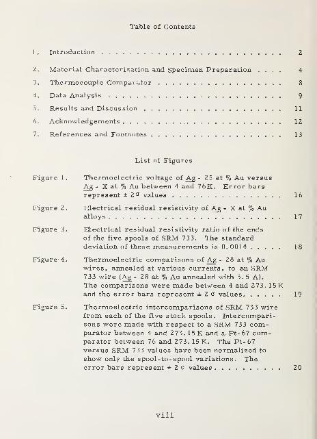
Table of Contents
1 . Introduction 2
2. Material Characterization and Specimen Preparation .... 4
3. Thermocouple Comparator 8
4. Data Analysis 9
5. Results and Discussion 11
6. Acknowledgements 12
7. References and Footnotes 13
List of Figures
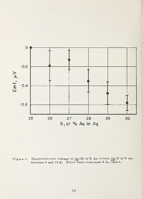
Figure 1. Thermoelectric voltage of Ag - 25 at % Au versusAg - X at % Au between 4 and 76 K. Error barsrepresent ±2'^ values 16
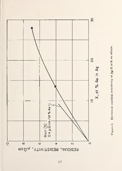
Figure 2. Electrical residual resistivity of Ag - X at % Aualloys 17
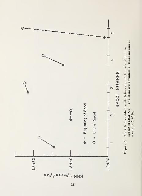
Figure 3. Electrical residual resistivity ratio of the endsof the five spools of SRM 733. The standarddeviation of these measurements is 0.0014 18
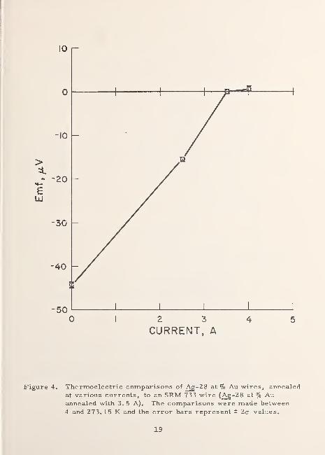
Figure 4. Thermoelectric comparisons of Ag - 28 at % Auwires, annealed at various currents, to an SRM733 wire (Ag - 28 at % Au annealed with 3.5 A).
The comparisons were made between 4 and 273. 15 Kand the error bars represent ± 2 a values 19
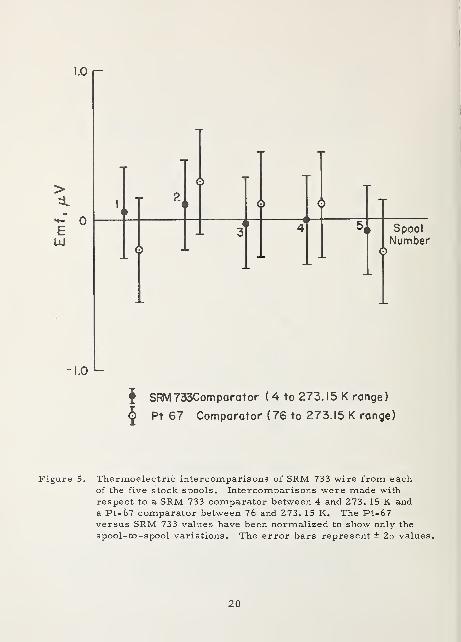
Figure 5. Thermoelectric intercomparisons of SRM 733 wirefrom each of the five stock spools. Intercompari-sons were made with respect to a SRM 733 com-parator between 4 and 273. 15 K and a Pt-67 com-parator between 76 and 273. 1 5 K. The Pt-67versus SRM 733 values have been normalized to
show only the spool-to- spool variations. Theerror bars represent ± 2 a values 20
viiiI
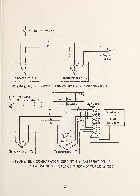
Figure 6a. Typical Thermocouple Arrangement 21
Figure 6b. Comparator Circuit for Calibration of StandardReference Thermocouple Wires 21
Figure 7a. Details of comparator construction (pictorial
view) 22
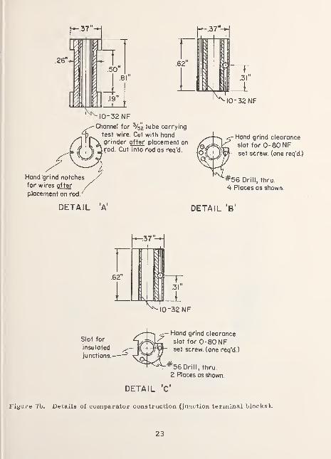
Figure 7b. Details of comparator construction (junction
terminal blocks ) 23
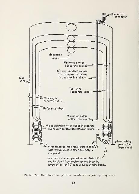
Figure 7c. Details of comparator construction (wiring
diagram) 24
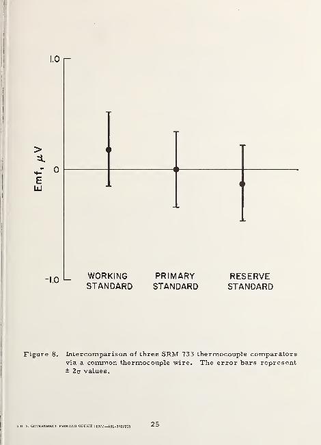
Figure 8. Intercomparison of three SRM 733 thermocouplecomparators via a common thermocouple wire.
The error bars represent ± 2 a values 25
List of Tables
Table 1. Chemical Composition of SRM 733 14
Table 2. Thermoelectric voltage for SRM 733 versuscommonly used thermocouple wire between liquid
helium and ice fixed points 15
ix

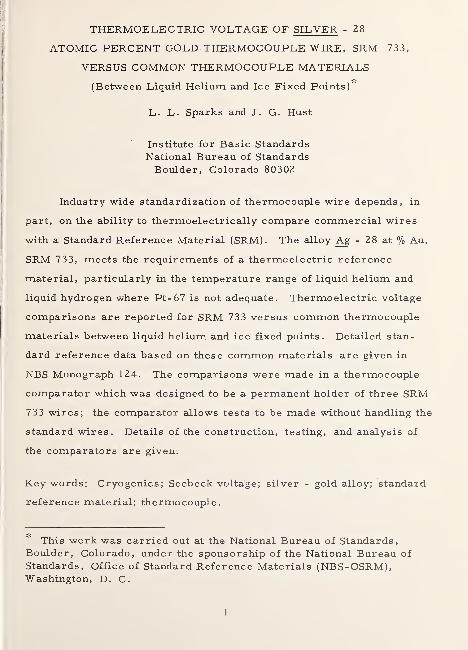
THERMOELECTRIC VOLTAGE OF SILVER - 28
ATOMIC PERCENT GOLD THERMOCOUPLE WIRE, SRM 733,
VERSUS COMMON THERMOCOUPLE MATERIALS
(Between Liquid Helium and Ice Fixed Points)''~
L. L. Sparks and J. G. Hust
Institute for Basic StandardsNational Bureau of StandardsBoulder, Colorado 80302
Industry wide standardization of thermocouple wire depends, in
part, on the ability to thermoelectrically compare commercial wires
with a Standard Reference Material (SRM). The alloy Ag - 28 at % Au,
SRM 733, meets the requirements of a thermoelectric reference
material, particularly in the temperature range of liquid helium and
liquid hydrogen where Pt-67 is not adequate. Thermoelectric voltage
comparisons are reported for SRM 733 versus common thermocouple
materials between liquid helium and ice fixed points. Detailed stan-
dard reference data based on these common materials are given in
NBS Monograph 124. The comparisons were made in a thermocouple
comparator which was designed to be a permanent holder of three SRM
733 wires; the comparator allows tests to be made without handling the
standard wires . Details of the construction, testing, and analysis of
the comparators are givexi.
Key words: Cryogenics; Seebeck voltage; silver - gold alloy; standard
reference material; thermocouple.
* This work was carried out at the National Bureau of Standards,Boulder, Colorado, under the sponsorship of the National Bureau of
Standards, Office of Standard Reference Materials (NBS-OSRM),Washington, D. C.
1
IJ Introdaction
The ability to standardize thermocouple wires depends, in part,
on the availability of a reliable StcUidard Reference Material (SRM). In
addition, thermocouple materials must be well characterized if exces-
sive manufacturer-to-manufacturer, batch-to-batch, or spool-to-spool
variations are to be avoided. Because of the difficulty of accurately
characterizing thermocouple wires in terms of composition or other
commonly used parameters, they must be controlled primarily by direct
thermoelectric measurements. If these direct thermoelectric measure-
ments are made with respect to an SRM which, in turn, is compared to
standard reference data, then industry-wide uniformity is possible. The
first step of this program, to establish such standard reference data
for commonly used thermocouples at cryogenic temperatures, has been
completed by Sparks, et al., [1] at the National Bureau of Standards,
Boulder, Colorado. The next step, to establish an SRM, is
the subject of this paper.
The general requirements for a thermoelectric SRM are that the
material:
(1) be insensitive in thermoelectric power to small changes in
composition,
(2) be readily fabricated into the desired form and quantity at
reasonable cost, and
2
(3) be easy to use in practice, i. , be flexible, ductile, and
chemically compatible with the measurement system.
In some instances it is also important to have a material with low ther-
mal conductivity and a thermoelectric power near the median of the
thermoelectric power of commonly used thermocouple materials.
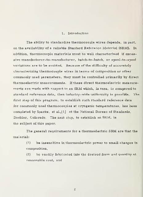
Tests made earlier in this laboratory by Powell, et al. , [z]
on a series of silver -gold alloys (20 to 40 atomic percent gold) indicated
that silver with approximately 25 to 30 at % gold met the above require-
ments. Since that time, more extensive tests have been performed
on six silver -gold alloys (25, 26, 27, 28, 29, and 30 at % gold).
These tests were conducted with experimental arrangements described
in a later section. The results of these measurements, figure 1, show
that the systematic emf variation among these wires (from 4 to 76 K)
is small (approximately 0. 1 |jV/at % Au). Based on the previous
measurements by Powell, et al., [z] and these later measurements,
silver - 28 at % gold was selected as a suitable low temperature
thermoelectric SRM. This report describes the research performed
to establish and maintain this silver -gold alloy as an SRM.
Traditionally, platinum is used by thermocouple wire manu-
facturers for production control. At temperatures above approxi-
mately 50 K platinum is a suitable SRM; however, below 50 K the
thermoelectric power of platinum becomes sensitive to physical
imperfections and trace chemical impurities, notably iron. This
low-temperature sensitivity to imperfections i? typical for pure
materials. In view of past use, applicability at higher temperatures,
extensive characterization, and availability in the form of homo-
geneous wire, platinum will also be maintained as a low
temperature thermoelectric SRM. A report on platinum dS such a
3
stcindard will be a subsequent publication in this series. It is to be 1
remembered that at lower temperatures (~ 4 K) spurious emfs
generated by inhomogeneities in platinum may be as much as ten times
greater than the spurious emfs found with the silver -28 at % gold alloy.
Thus, platinum is recommended for measurements at temperatures as
low as liquid nitrogen (76 K) and the silver -gold alloy is recommended
for measurements below 76 K.
2. Material Characterization and Specimen Preparation
A specially prepared lot of Ag -28 at % Au alloy was fabricated as
wire for further testing and to establish and maintain a thermoelectric
standard. The metal was alloyed and cast in 2. 5 cm diameter billets.
The billets were swaged to 0. 6 cm diameter, drawn to 0. 06 cm with
carbide dies, ajid finally drawn to 0. 020 cm (0. 008 inch) wire with
diamond dies. Drawing was accomplished without lubricant and
without annealing or etching between passes. The wire was supplied
uninsulated to facilitate later annealing. Annealing is necessary
to eliminate physical damage introduced by normal handling, e. g. ,
winding cind unwinding from the spools. The chemical composition
of the wire is given in table 1.
The Ag-Au standard wire was supplied on five spools.
Specimens were cut from both ends of each spool for characterization
measurements. The residual resistivity ratios (RRR = P1s73k/P4K>
where p = electrical resistivity) of these 10 specimens were determined
after annealing at 400''C for one hour. Variation in the residual re-
sistivity ratio of annealed specimens indicates variation in composi-
tion. The composition variation can be determined from RRR variation
if one knows the specific resistivity, bp^/'bC (p^ = residual resistivity and
C = relative composition in atomic units). BlattLs] has compiled values
of specific
4
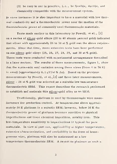
resistivity for many elements and lists 0. 4 cm/at % Au in Ag. We
have performed RRR measurements on Ag - 13. 5 at % Au as well as the
Ag -28 at % Au alloy. From an approximate (±3%) resistivity measure-
ment and by the application of Matthiessen' s rule, we obtain values of
versus composition as shown in figure 2. Blatt's [3] specific resistivity,
3P^/BC, is in reasonable agreement with the slope of our curve in figure
2 at low Au concentration. If we assume the form of the residual resis-
tivity — composition relation suggested by Nordheim [4], = 0!C{1 - C),
and evaluate the best estimate of a, we obtain 0. 35 p,^cm/at % Au as
compared to 0. 40 |j,ji.cm/at % Au listed by Blatt [3].
Using Nordheim' s rule, we have shown that the change in atomic
percent composition, AC, is related to change in residual resistivity ratio,
ARRR, as follows:
Ar - ARRR C(l - C)^ (RRR - 1) (1 - 2C) • ^
'
The determination of RRR instead of p eliminates the need to determineo
the form factor (cross-sectional area/length) of the specimen; therefore,
the results are both more precise and accurate. The range of RRR vari-
ation, ARRR, measured for the ten specimens from the ends of the five
spools is 0. 0044, as shown in figure 3. This variation in RRR corresponds
to about 0. 7 atomic percent variation in gold concentration and apparently
is random over the five spools. The thermoelectric variation caused by
a 0. 7 atomic percent composition variation is undetectable, as shown in
figure 1. Thus, specimens from the five spools of material should be
thermoelectrically indistinguishable.
5
Specimen preparation is important in obtaining uniform standard
reference thermocouple specimens. The wire must be cleanedj aruiealed,
and subsequently handled with care to avoid chemical contamination or
physical damage, either of which can affect thermoelectric power.
Several preanneal cleaning and etching procedures were considered
in order to prevent diffusion of impurities into the wire during the
anneal. It was determined that cleaning with a degreasing agent
followed by rinsing in distilled water was adequate. Etching the sur-
face did not make a detectable difference in thermoelectric properties.
Several cuinealing procedures were also investigated. As a first attempt,
the wire was degreased, washed in distilled water, and wrapped on a
fused quartz spool. This wire was annealed in an air furnace for one
hour at 400°C. This procedure proved unsatisfactory because there
was a tendency for the wire to adhere to the spool after annealing; re-
moving the wire from the spool undoubtedly introduced some strain.
Resistance annealing, i. e. , self heating caused by an electric current
through the wire^ resulted in wires which were thermoelectrically more
reproducible. This procedure is convenient and can be done with less
chance of chemical contamination or physical strain. The effect of
different annealing currents is shown in figure 4. Based on this, an
annealing current of 3. 5 A through the 0. 020 cm diameter wire was
selected as optimum. This current produced a dull red glow (hardly
visible in a darkened room) and resulted in a well-annealed wire. We
found that the Ag-Au wire is weakened and will break with very low
stress after a 4^ 3 A anneal. This may be caused by grain growth
across the wire during the anneal and subsequent hydrogen diffusion
into the grain boundary. These 0. 020 cm diameter wires melt at
currents slightly above 4. 3 A. The recommended wire preparation
procedure is:
6
1. Degrease and rinse in distilled water.
2. Suspend wire in air and connect to a current source.
3. Continuously increase current to obtain proper annealing
temperature (3. 5 A for the 0. 020 cm diameter wire).
4. Maintain this temperature for about 30 seconds.
5. Gradually decrease current to zero over about 15 seconds.
6. Handle with care: avoid unnecessary mechanical stresses
of the wire prior to use.
Specimen wires from each of the five spools of the Ag -Au alloy
were thermoelectric ally intercompared after being prepared as above.
The results, shown in figure 5, show that statistically no difference in
thermoelectric power exists among the wires from the five spools.
These comparisons were made with respect to a SRM 733 comparator
for temperatures from 4 to 273. 15 K and a Pt-67 comparator for tem-
peratures from 76 to 273. 15 K. The results from the Pt-67 comparator
have been normalized so as to show only the spool-to-spool variation.
These thermoelectric intercomparisons are in accord with the pre-
viously mentioned resistivity results.
The preceding results, in some instajices, were obtained with
thermocouple comparators. The design and construction of the com-
parators are described in the next section.
7
I
3. Thermocouple Comparator 1
The basic measurement arrangement for a thermocouple calibra-|
tion measurement is shown in figure 6a. This arrangement is used to
determine the difference in thermoelectric emfs, - of wires A iA Band B between temperatures T^ and Tg. The average thermopower, S,
of the thermocouple is defined by (E^ - Eg)/(T2 r T^). Errors are\
introduced into this measurement by (1) the presence of spurious thermal '
emfs caused principally by wire inhomogeneity in regions of high tem-
perature gradient, and (2) improper thermal anchoring to each of the baths.
It is possible to reduce the systematic effect of spurious voltages by taking
readings at different immersion depths and by measuring with respect to
more than one reference wire.
The thermal anchoring problem is solved by reducing the thermal
resistance between the wires and the constant temperature baths. This is
accomplished by intimate contact between the wires and the liquid over a
sufficient length leading up to the thermocouple junctions. This problem
has been examined carefully both experimentally and theoretically [ 5] .
No detectable error due to inadequate thermal anchoring is believed
present in the thermoelectric emfs reported here. The thermocouple
comparator is shown schematically in figure 6b. The selector switch
allows one to measure the thermoelectric emf of the test wire with respect
to each of the reference wires as well as to inter compare each of the
reference wires. Inter comparison of the reference wires is done
to detect possible deterioration of these wires or other comparator com-
ponents. The construction details of the comparator are shown in figures
7a, 7b, and 7c.
8
4. Data Analysis
The experimental data, depicted in figure 6b, are designated
as E^j, E^2'^T3' "^12' ^23' ^13' subscript T indicates the
test wire while 1, 2, and 3 refer to the three standard reference wires
permanently installed in the comparator. A set of six voltages is
obtained for each immersion depth in the forward (T^ to T^) direction
as well as in the reverse (T^ to T ^) direction. The values obtained in the
forward direction, averaged over the various depths, will be designated by
E. .(F), while the reverse readings are designated E. .(R). The sets of
six voltages are illustrated in the following measurement graph.
T
In this figure the vertices represent the wires illustrated and defined in
figure 6b, while the lines represent the emfs of the associated thermo-
couple pairs. For convenience, the vertical position of the vertices
designate the relative position of each wire in the electromotive series,
e. g. , the most theirmoelectrically positive wire is denoted by the upper-
most vertex. The most probable (weighted averages) values E^^, E^^'
E^2» -^12' "^13' ^23 obtained from the redundant but independent
equations based on the various paths which can be used to define each E_.
There are four such independent paths which can be used to obtain four
estimates of each measured voltage. As an example, the four independent
paths used to estimate E yield the following four equations:
9
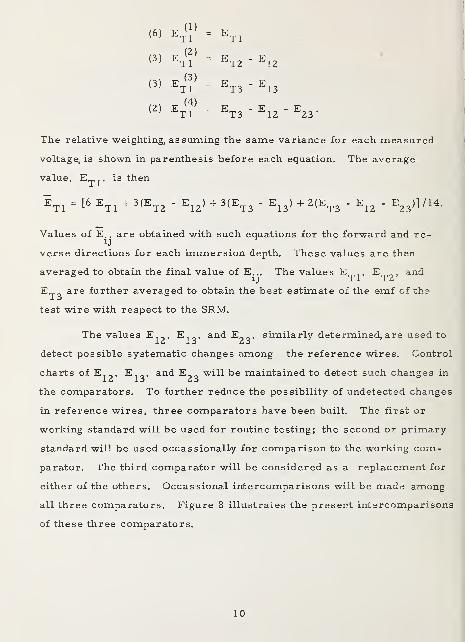
(6) = ^Tl
(3) F -
^Tl-
'- ^T2 -^12t
(3) E -
= ^T3 -^13
(2) F -
^Tl-= ^T3 -^12-^23-
The relative weighting, as suming the same variance for each measured
voltage, is shown in parenthesis before each equation. The average
value,J
, is then
Values of E.. are obtained with such equations for the forward and re-
verse directions for each immersion depth. These values are then
averaged to obtain the final value of E_. The values E^^, E^^' ^-^^
E^^ are further averaged to obtain the best estimate of the emf of the
test wire with respect to the SRM.
The values E^^. E,^, and E^^j similarly determined, are used to
detect possible systematic changes among the reference wires. Control
charts of E^^' -^13' ^23 ^^^^ ^® maintained to detect such changes in
the comparators. To further reduce the possibility of undetected changes
in reference wires, three comparators have been built. The first or
working standard will be used for routine testing; the second or primary
standard will be used occassionalLy for comparison to the working com-
parator. The third comparator will be considered as a replacement for
either of the others. Occassional intercomparisons will be made among
all three comparators. Figure 8 illustrates the present intercomparisons
of these three comparators.
10
The determination of the emf of a test wire with respect to the
standard reference thermocouple wire is summarized below:
(1) Record the six emfs illustrated in the previous measure-
ment graph.
(2) Repeat step 1 for three immersion depths to randomize
spurious emfs.
(3) Repeat (1) and (2) with comparator reversed in the baths.
(4) Compute the most probable values of the six sets of six
voltages using all of the redundancy in the data, both for the forward
and reverse directions.
(5) Compute the average emf for the test wire with respect to
the reference standard
^TR = [(^Tl + ^TZ + Et3)fWd/^ +(=T1 + ^T2 + ^TsXey/']
and the variance of this emf. This variance is based upon the random
scatter indicated by the redundancy of these measurements.
5. Results and Discussion
SRM 733 is intended for use as a standard reference thermo-
couple wire at low temperatures. In order for this wire to be useful,
one must know the emf generated by this wire with respect to
commonly used thermocouple materials. The temperature interval
chosen for standardization of these wires with respect to SRM 733 is
4 to 273. 15 K. The data are based on the extensive measurements of
Sparks, et al., [l] and more recent measurements as explained in
table 2c The emf of SRM 733 with respect to commonly used wires
over the range 4 to 273. 15 K are presented in table 2.
11
standardization measurements have been made at several1
intra-spool locations to insure that the variability of SRM 733 does!
not exceed that reported here. As pointed out earlier, this possibilityj
is remote because the emf of SRM 733 is insensitive to composition '
change.
Consideration has been given to extending the calibration range
of SRM 733 to higher temperatures. The upper limit of usefulness
would be dictated by the temperature produced by the optimum anneal
described in this paper. This temperature is approximately 500 °C.
At the present time the demand for this extension does not justify the
additional effort, especially since Pt-67 can be used in this range.
SRM 733, issued as 32 AWG wire, 3 meters long, may be
ordered from the Office of Standard Reference Materials, Room 3314,
Chemistry Building, National Bureau of Standards, Washington, D.C.
20234. (Longer continuous lengths in multiples of 3 meters can be
obtained by special order to the OSRM).
6. Acknowledgements
We wish to thank the thermocouple manufacturers, especially
Sigmxand-Cohn Corp. , Cominco American, Inc. , and Engelhard
Industries, Inc. , for their cooperation in this program. This program
was initiated and directed in its early stages by R. L. Powell; we
also thank him for his many suggestions throughout the program.
12
7. References and Footnotes
[l] Sparks, L. L. ,Powell, R. L. , and H all, W. J., Reference
Tables for Low-Temperature Thermocouples, NBS (U. S. )»
Monogr. 124.
[2] Powell, R. L.,Caywood, L. P., Jr., and Bunch, M. D.
,
Low Temperature Thermocouples, Temperature -Its
Measurement and Control in Science and Industry 3, part 2,
65 (1962).
[3] Blatt, F. J., Physics of Electronic Conduction in Solids,
McGraw-Hill Book Co. , N. Y. , p. 199 (1968).
[4] Ziman, J. M. , Electrons ajid Phonons, Oxford at the
Clarendon Press, p. 337 (I960).
[5] Hust, J. G. , Thermal Anchoring of Wires in Cryogenic
Apparatus, Rev. Sci. Instr. 41, 622-624 (1970).
[6] Trademark - Wilbur B. Driver Co.
[7] Trademark - Driver-Harris Co.
[S] Trademark - Kanthal Corp.
[9] Trademark - Hoskins Manufacturing Co.
[10] The use of tradenames of specific products is essential to the
proper understanding of the work presented here. Their use
in no way implies approval, endorsement, or recommendation
by NBS.
13
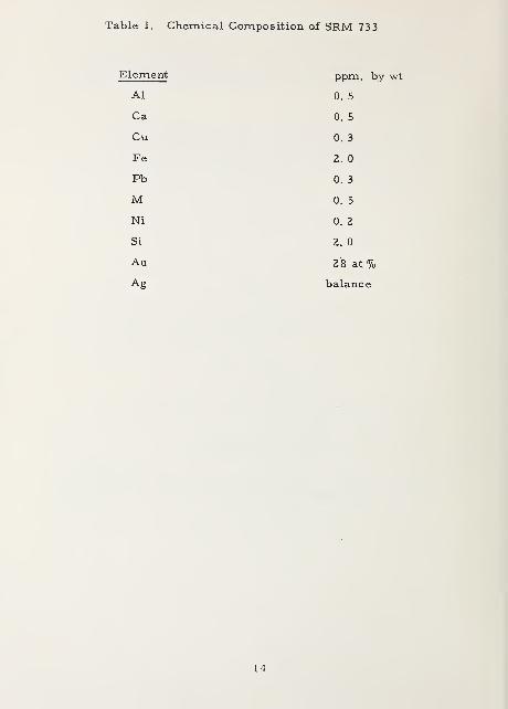
Table 1. Chemical Composition of SRM 733
Element ppm, by
Al 0. 5
Ca 0. 5
Cu 0. 3
Fe 2. 0
Pb 0. 3
M 0. 5
Ni 0. 2
Si 2. 0
Au 28 at %
Ag balance
14
Table 2. Thermoelectric voltage for SRM 733 versus commonly used
thermocouple wire between liquid helium and ice fixed points,
^ +Thermocouple EMF, ^V
Pt vs SRM 733 541 ± 3
KP or EP** vs SRM 733 4098. 3 ± 0. 8
TP** vs SRM 733 521. 8 ± 0. 8
5735.2 ± 0. 8
2358. 7 ± 0. 8
These data are calculated from reference data by Sparks, et al.,[l]
and more recent comparisons of the emf of SRM 733 (resistance
annealed at 3.5 A) to the Ag-28 at % Au wire used in [l] which wasoven annealed at 400°C for 1 hour. The Pt-67 wire used here wasresistance annealed at 10 95°C for 1 minute.
t The uncertainties given are twice the estimated standard deviations.
The larger uncertainty for Pt reflects the sensitivity of this purematerial to trace impurities at liquid helium temperature. Theeffect of these impurities is strongly dependent on the temperaturedistribution along the wire. For dip tests, where the temperaturegradient along the wire is extremely localized, a range of thermalvoltages as large as 15 \j.V has been observed.
EN or TN A copper-nickel alloy, constantan, Cupron [6],
Advance [7], Thermo Kanthal JN [8].
KP or EP A nickel-chromium alloy, Chromel [9], Tophel [6],
T-1 L7j, Thermo Kanthal KP [8].
KN A nickel
-
aluminum alloy, Alumel [9], Nial [6],
T-2 L7j, Thermo Kanthal [8].
TP Copper, usually electrolytic tough pitch.
The use of trade names does not constitute axi endorsement of anymanufacturer's products. Materials manufactured in compliance withestablished standards are equally suitable.
15
0 #
-0.2
>
25 26 27 28 29 30
X,at % Au in Ag
Figure 1. Thermoelectric voltage of Ag-25 at % Au versus Ag-X at % Aubetween 4 amd 76 K. Error bars represent ± 2a values.
16
\
<
O
c1—1 o
o ^CD C>
oCVJ
<
<
o 00 to oj o
uJi)U^ *AllAllSIS3d ivnais3d
17
CD
O
i
ooa.</>
oocx
OOQ.
O,
m UJ
18
I
0,1 2 3 4
CURRENT, A
Figure 4. Thermoelectric comparisons of Ajg-28 at % Au wires, annealedat various currents, to an SRM 733 wire (Ag -28 at % Aueinnealed with 3. 5 A). The comparisons were made between4 and 273. 15 K and the error bars represent ± 2a values.
19
1.0I
>
^ 0E Spool
Number
1.0
i SRM733ComparGtor (4 to 273.15 K range)
^ Pt 67 Comparator (76 to 273.15 K range)
Figure 5. Thermoelectric intercomparisons of SRM 733 wire from eachof the five stock spools. Intercomparisons were made with
respect to a SRM 733 comparator between 4 and 273. 15 K anda Pt-67 comparator between 76 and 273. 15 K. The Pt-67versus SRM 733 values have been normalized to show only the
spool-to-spool variations. The error bars represent ± 2a values.
20
Thermal Anchor
I Temperature = Ti
I ^^J
Temperature ~ '^Zj
CopperWires
FIGURE 6a - TYPICAL THERMOCOUPLE ARRANGEMENT
T = Test Wire
Reference Wire #1
jJTemperature = T|
[
Potentiometer
and
Null
Detector
Temperature = T
FIGURE 6b- COMPARATOR CIRCUIT for CALIBRATION of
STANDARD REFERENCE THERMOCOUPLE WIRES
21
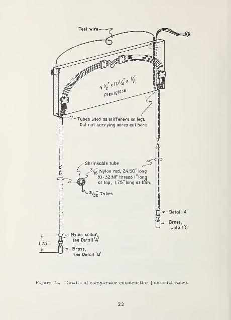
Figure 7a. Details of comparator construction (pictorial view).
22
^ 10-32 NF
Channel for tube carrying
test wire. Cut with handgrinder after piacennent onrod. Cut into rod as req'd.
Hand grind notches
for wires after
placement on rod.
10-32 NF
Hand grind clearance
slot for 0-80 NFset screw, (one req'd.)
*56 Drill, thru.
4 Places as shown.
DETAIL 'A' DETAIL 'B'
^^-^p"! ^ Hand grind clearanceSlot for A .AJ slot for 0 - 80 N Finsulated ^HVtJ^ set screw, (one req'd.)
junctions.
"^Se Drill, thru.
2 Places as shown.
DETAIL 'C'
Figure 7b. Details of comparator construction (junction terminal blocks ^.
23
Electricalconnector
Expansion
loop
Reference wires
{Separate Tubes)-
6 Long , 32 AW6 copper
Instrumentation wires
in one flexible tube.
Test wire
(Separate Tube)
All wires in
separate tubes.
Reference wires
Wound on nylon
collar (one layer)—
Swires wound on nylon collar in separate
layers with teflon tape between layers.
I
....^ Wires soldered into brass ( Details BSC)with Wood's metal, (after assembly is
complete).
Junctions soldered, placed in slot (Detail 'C'
and insulated from each other and brass by
layers of Teflon [10] tape secured by wire bands.
^Low melting- <- point solder
(both ends)
Details of comparator construction (wiring diagram).
24
WORKING PRIMARY RESERVESTANDARD STANDARD STANDARD
Figure 8. Intercomparison of three SRM 733 thermocouple comparatorsvia a common thermocouple wire. The error bars represent± 2ct values.
U. S. GOVERNMENT PRINTING OFFICE : 1972—481-332/206 25
FORM NBS-114A (1-71)
U.S. DEPT. OF COMM. 1. PUBLICATION OR REPORT NO. 12, Gov't Accession
BIBLIOGRAPHIC DATA NBS SP 260-341
SHEET
3. Recipient's Accession No.
4. TITLE AND SUBTITLEThermoelectric Voltage of Silver - 28 Atomic Percent Gold
Thermocouple Wire, SRM 733, Versus Common Thermocoupl^Materials (Between Liquid Helium and Ice Fixed Points)
5. Publication Date
March 1972'6. Performing Organization Code
7. AUTHOR(S)
L. L. Sparks and J. G. Hust8. Performing Organization
9. PERFORMING ORGANIZATION NAME AND ADDRESS
NATIONAL BUREAU OF STANDARDSDEPARTMENT OF COMMERCEBoulder, Colorado 80302
10. Project/Task/Work Unit No.
Project 275275911. Contract/Grant No.
NBS-OSRM12. Sponsoring Organization Name and Address
National Bureau of Standardsr^ff\i-e^ rif <^f a r\ r\ a r r\ R f»f r f^n f AAatf^rialQ ^ TMR c; _ Oc; R A/T ^
Washington, D. C
13. Type of Report & PeriodCovered
Final14. Sponsoring Agency Code
15. SUPPLEMENTARY NOTES
16. ABSTRACT (A 200-'word or less factual summary of most significant information. If document includes a significantbibliography or literature survey, mention it here.)
Industry wide standardization of thermocouple wire depends, in part, on
the ability to thermoelectrically compare commercial wires with a StandardReference Material (SRM). The alloy Ag - 28 at % Au, SRM 733, meets the
requirements of a thermoelectric reference material, particularly in the tempera-ture range of liquid helium and liquid hydrogen where Pt-67 is not adequate.
Thermoelectric voltage comparisons are reported for SRM 733 versus commonthermocouple materials between liquid helium and ice fixed points. Detailed
standard reference data based on these common materials are given in NBSMonograph 124. The comparisons were made in a thermocouple comparatorwhich was designed to be a permanent holder of three SRM 733 wires; the
comparator allows tests to be made without handling the standard wires. Details
of the construction, testing, and analysis of the comparators are given.
17. KEY WORDS (Alphabetical order, separated by semicolons) Cryogenics; Seebeck voltage; silver-gold
alloy; standard reference material; thermocouple.
18. AVAILABILITY STATEMENT
[xH UNLIMITED.
FOR OFFICIAL DISTRIBUTION. DO NOT RELEASETO NTIS.
19. SECURITY CLASS(THIS REPORT)
UNCL ASSIFIED
20. SECURITY CLASS(THIS PAGE)
UNCLASSIFIED
21. NO. OF PAGES
34
22. Price
USCOMM-DC 66244. P71
NBS TECHNICAL PUBLICATIONS
PERIODICALS
JOURNAL OF RESEARCH reports National
Bureau of Standards research and development in
physics, mathematics, chemistry, and engineering.
Comprehensive scientific papers give complete details
of the work, including laboratory data, experimental
procedures, and theoretical and mathematical analy-
ses. Illustrated with photographs, drawings, andcharts.
Published in three sections, available separately:
• Physics and Chemistry
Papers of interest primarily to scientists working in
these fields. This section covers a broad range of
physical and chemical research, with major emphasis
on standards of physical measurement, fundamentalconstants, and properties of matter. Issued six times
a year. Annual subscription: Domestic, $9.50; $2.25
additional for foreign mailing.
• Mathematical Sciences
Studies and compilations designed mainly for the
mathematician and theoretical physicist. Topics in
mathematical statistics, theory of experiment design,
numerical analysis, theoretical physics and chemis-
ty, logical design and programming of computers
and computer systems. Short numerical tables. Issued
quarterly. Annual subscription: Domestic, $5.00;
$1.25 additional for foreign mailing.
• Engineering and Instrumentation
Reporting results of interest chiefly to the engineer
and the applied scientist. This section includes manyof the new developments in instrumentation resulting
from the Bureau's work in physical measurement,data processing, and development of test methods.
It will also cover some of the work in acoustics,
applied mechanics, building research, and cryogenic
engineering. Issued quarterly. Annual subscription:
Domestic, $5.00; $1.25 additional for foreign mailing.
TECHNICAL NEWS BULLETIN
The best single source of information concerning the
Bureau's research, developmental, cooperative, andpublication activities, this monthly publication is
designed for the industry-oriented individual whosedaily work involves intimate contact with science andtechnology
—
for engineers, chemists, physicists, re-
search managers, product-development managers, andcompany executives. Annual subscription: Domestic,
$3.00; $1.00 additional for foreign mailing.
Order NBS publications from:
NONPERIODICALS
Applied Mathematics Series. Mathematical tables,
manuals, and studies.
Building Science Series. Research results, test
methods, and performance criteria of building ma-terials, components, systems, and structures.
Handbooks. Recommended codes of engineering
and industrial practice (including safety codes) de-
veloped in cooperation with interested industries,
professional organizations, and regulatory bodies.
Special Publications. Proceedings of NBS confer-
ences, bibliographies, annual reports, wall charts,
pamphlets, etc.
Monographs. Major contributions to the technical
literature on various subjects related to the Bureau's
scientific and technical activities.
National Standard Reference Data Series.
NSRDS provides quantitative data on the physical
and chemical properties of materials, compiled fromthe world's literature and critically evaluated.
Product Standards. Provide requirements for sizes,
types, quality, and methods for testing various indus-
trial products. These standards are developed co-
operatively with interested Government and industry
groups and provide the basis for common understand-
ing of product characteristics for both buyers andsellers. Their use is voluntary.
Technical Notes. This series consists of communi-cations and reports (covering both other agency andNBS-sponsored work) of limited or transitory interest.
Federal Information Processing StandardsPublications. This series is the official publication
within the Federal Government for information on
standards adopted and promulgated under the Public
Law 89-306, and Bureau of the Budget Circular A-86entitled, Standardization of Data Elements and Codes
in Data Systems.
Consumer Information Series. Practical informa-
tion, based on NBS research and experience, covering
areas of interest to the consumer. Easily understand-
able language and illustrations provide useful back-
ground knowledge for shopping in today's technolog-
ical marketplace.
NBS Special Publication 305, Supplement 1,
Publications of the NBS, 1968-1969. When order-
ing, include Catalog No. CI 3. 10: 305. Price $4.50;
$1.25 additional for foreign mailing.
Superintendent of DocumentsGovernment Printing Office
Washington, D.C. 20402
U.S. DEPARTMENT OF COMMERCENational Bureau of StandardsWashington. D.C. 20234
OFFICIAL BUSINESS
Penalty for Private Use, S300
POSTAGE AND FEES PAIDU.S. DEPARTMENT OF COMMERCE