Embed Size (px)
Citation preview

Designation: D4057 − 12
Manual of Petroleum Measurement Standards (MPMS), Chapter 8.1
Standard Practice forManual Sampling of Petroleum and Petroleum Products1
This standard is issued under the fixed designation D4057; the number immediately following the designation indicates the year oforiginal adoption or, in the case of revision, the year of last revision. A number in parentheses indicates the year of last reapproval. Asuperscript epsilon (´) indicates an editorial change since the last revision or reapproval.
This standard has been approved for use by agencies of the U.S. Department of Defense.
INTRODUCTION
The previous version of the manual sampling practice described the various sampling methods andapparatus, with much focus on crude oils and semi-solids and solids. Also, previous versions did notsignificantly address closed or restricted sampling, which continue to become more prevalent.
This version will provide guidance on manual sampling terminology, concepts, equipment,containers, procedures, and will provide some specific guidance related to particular products andtests. The type and size of the sample obtained, and the handling method, will depend on the purposefor which it was taken. Refer to the test method for any specific sampling and handling requirementsup to the point of testing. It remains the responsibility of the subcommittee for the relevant test methodto provide guidance, or warnings, regarding sample container selection; preparation; cleanliness; heat,pressure, or light; sample size requirements for testing and retention; and any other special handlingrequirements necessary to ensure a representative sample is tested.
In addition to the individual test method, for guidance on container, size, mixing and specialhandling, further guidance may be provided in Practice D5854 (API MPMS Chapter 8.3), PracticeD5842 (API MPMS Chapter 8.4), and Practice D4306. While this practice will provide some generalguidance regarding sample chain of custody, Guide D4840 should also be consulted.
This document has been developed jointly between the American Petroleum Institute (API) andASTM International.
1. Scope
1.1 This practice covers procedures and equipment formanually obtaining samples of liquid petroleum and petroleumproducts, crude oils, and intermediate products from thesample point into the primary container are described. Proce-dures are also included for the sampling of free water and otherheavy components associated with petroleum and petroleumproducts.
1.2 This practice also addresses the sampling of semi-liquidor solid-state petroleum products.
1.3 This practice provides additional specific informationabout sample container selection, preparation, and samplehandling.
1.4 This practice does not cover sampling of electricalinsulating oils and hydraulic fluids. If sampling is for theprecise determination of volatility, use Practice D5842 (APIMPMS Chapter 8.4) in conjunction with this practice. Forsample mixing and handling, refer to Practice D5854 (APIMPMS Chapter 8.3).
1.5 The procedures described in this practice may also beapplicable in sampling most non-corrosive liquid industrialchemicals provided that all safety precautions specific to thesechemicals are followed. Also, refer to Practice E300. Theprocedures described in this practice are also applicable tosampling liquefied petroleum gases and chemicals. Also referto Practices D1265 and D3700. The procedure for samplingbituminous materials is described in Practice D140. PracticeD4306 provides guidance on sample containers and prepara-tion for sampling aviation fuel.
1 This practice is under the jurisdiction of ASTM Committee D02 on PetroleumProducts, Liquid Fuels, and Lubricants and the API Committee on PetroleumMeasurement and is the direct responsibility of Subcommittee D02.02 /COMQ onHydrocarbon Measurement for Custody Transfer (Joint ASTM-API). This practicehas been approved by the sponsoring committees and accepted by the CooperatingSocieties in accordance with established procedures. This practice was issued as ajoint ASTM-API standard in 1981.
Current edition approved Dec. 1, 2012. Published October 2013. Originallyapproved in 1981. Last previous edition approved in 2011 as D4057 – 06 (2011).DOI: 10.1520/D4057-12.
Copyright © ASTM International, 100 Barr Harbor Drive, PO Box C700, West Conshohocken, PA 19428-2959. United States
1

1.6 Units—The values stated in SI units are to be regardedas the standard. USC units are reflected in parentheses.
1.7 This standard does not purport to address all of thesafety concerns, if any, associated with its use. It is theresponsibility of the user of this standard to establish appro-priate safety and health practices and determine the applica-bility of regulatory limitations prior to use.
2. Referenced Documents
2.1 ASTM Standards:2
D86 Test Method for Distillation of Petroleum Products atAtmospheric Pressure
D97 Test Method for Pour Point of Petroleum ProductsD140 Practice for Sampling Bituminous MaterialsD217 Test Methods for Cone Penetration of Lubricating
GreaseD244 Test Methods and Practices for Emulsified AsphaltsD268 Guide for Sampling and Testing Volatile Solvents and
Chemical Intermediates for Use in Paint and RelatedCoatings and Material
D287 Test Method for API Gravity of Crude Petroleum andPetroleum Products (Hydrometer Method)
D323 Test Method for Vapor Pressure of Petroleum Products(Reid Method)
D346 Practice for Collection and Preparation of CokeSamples for Laboratory Analysis
D445 Test Method for Kinematic Viscosity of Transparentand Opaque Liquids (and Calculation of Dynamic Viscos-ity)
D473 Test Method for Sediment in Crude Oils and Fuel Oilsby the Extraction Method (API MPMS Chapter 10.1)
D664 Test Method for Acid Number of Petroleum Productsby Potentiometric Titration
D977 Specification for Emulsified AsphaltD1265 Practice for Sampling Liquefied Petroleum (LP)
Gases, Manual MethodD1267 Test Method for Gage Vapor Pressure of Liquefied
Petroleum (LP) Gases (LP-Gas Method)D1298 Test Method for Density, Relative Density, or API
Gravity of Crude Petroleum and Liquid Petroleum Prod-ucts by Hydrometer Method (API MPMS Chapter 9.1)
D1657 Test Method for Density or Relative Density of LightHydrocarbons by Pressure Hydrometer (API MPMSChapter 9.2)
D1838 Test Method for Copper Strip Corrosion by LiquefiedPetroleum (LP) Gases
D1856 Test Method for Recovery of Asphalt From Solutionby Abson Method
D2172 Test Methods for Quantitative Extraction of BitumenFrom Bituminous Paving Mixtures
D2622 Test Method for Sulfur in Petroleum Products byWavelength Dispersive X-ray Fluorescence Spectrometry
D3230 Test Method for Salts in Crude Oil (ElectrometricMethod)
D3700 Practice for Obtaining LPG Samples Using a Float-ing Piston Cylinder
D4006 Test Method for Water in Crude Oil by Distillation(API MPMS Chapter 10.2)
D4007 Test Method for Water and Sediment in Crude Oil bythe Centrifuge Method (Laboratory Procedure) (APIMPMS Chapter 10.3)
D4177 Practice for Automatic Sampling of Petroleum andPetroleum Products (API MPMS Chapter 8.2)
D4294 Test Method for Sulfur in Petroleum and PetroleumProducts by Energy Dispersive X-ray Fluorescence Spec-trometry
D4306 Practice for Aviation Fuel Sample Containers forTests Affected by Trace Contamination
D4377 Test Method for Water in Crude Oils by Potentiomet-ric Karl Fischer Titration (API MPMS Chapter 10.7)
D4530 Test Method for Determination of Carbon Residue(Micro Method)
D4629 Test Method for Trace Nitrogen in Liquid PetroleumHydrocarbons by Syringe/Inlet Oxidative Combustion andChemiluminescence Detection
D4807 Test Method for Sediment in Crude Oil by Mem-brane Filtration (API MPMS Chapter 10.8)
D4840 Guide for Sample Chain-of-Custody ProceduresD4928 Test Method for Water in Crude Oils by Coulometric
Karl Fischer Titration (API MPMS Chapter 10.9)D4929 Test Methods for Determination of Organic Chloride
Content in Crude OilD5002 Test Method for Density and Relative Density of
Crude Oils by Digital Density AnalyzerD5191 Test Method for Vapor Pressure of Petroleum Prod-
ucts (Mini Method)D5762 Test Method for Nitrogen in Petroleum and Petro-
leum Products by Boat-Inlet ChemiluminescenceD5842 Practice for Sampling and Handling of Fuels for
Volatility Measurement (API MPMS Chapter 8.4)D5853 Test Method for Pour Point of Crude OilsD5854 Practice for Mixing and Handling of Liquid Samples
of Petroleum and Petroleum Products (API MPMS Chap-ter 8.3)
D5863 Test Methods for Determination of Nickel,Vanadium, Iron, and Sodium in Crude Oils and ResidualFuels by Flame Atomic Absorption Spectrometry
D6299 Practice for Applying Statistical Quality Assuranceand Control Charting Techniques to Evaluate AnalyticalMeasurement System Performance
D6377 Test Method for Determination of Vapor Pressure ofCrude Oil: VPCRx (Expansion Method)
D6470 Test Method for Salt in Crude Oils (PotentiometricMethod)
D6560 Test Method for Determination of Asphaltenes (Hep-tane Insolubles) in Crude Petroleum and Petroleum Prod-ucts
D6822 Test Method for Density, Relative Density, and APIGravity of Crude Petroleum and Liquid Petroleum Prod-ucts by Thermohydrometer Method (API MPMS Chapter9.3)
2 For referenced ASTM standards, visit the ASTM website, www.astm.org, orcontact ASTM Customer Service at [email protected]. For Annual Book of ASTMStandards volume information, refer to the standard’s Document Summary page onthe ASTM website.
D4057 − 12
2

D6849 Practice for Storage and Use of Liquefied PetroleumGases (LPG) in Sample Cylinders for LPG Test Methods
D7169 Test Method for Boiling Point Distribution ofSamples with Residues Such as Crude Oils and Atmo-spheric and Vacuum Residues by High Temperature GasChromatography
E300 Practice for Sampling Industrial ChemicalsE882 Guide for Accountability and Quality Control in the
Chemical Analysis Laboratory2.2 API Manual of Petroleum Measurement Standards:3
MPMS Chapter 8.2 Automatic Sampling of Petroleum andPetroleum Products (ASTM Practice D4177)
MPMS Chapter 8.3 Standard Practice for Mixing and Han-dling of Liquid Samples of Petroleum and PetroleumProducts (ASTM Practice D5854)
MPMS Chapter 8.4 Standard Practice for the Sampling andHandling of Fuels for Volatility Measurements (ASTMPractice D5842)
MPMS Chapter 9.1 Standard Test Method for Density, Rela-tive Density (Specific Gravity), or API Gravity of CrudePetroleum and Liquid Petroleum (ASTM Test MethodD1298)
MPMS Chapter 9.2 Standard Test Method for Density orRelative Density of Light Hydrocarbons by PressureHydrometer (ASTM Test Method D1657)
MPMS Chapter 9.3 Standard Test Method for Density, Rela-tive Density, and API Gravity of Crude Petroleum andLiquid Petroleum Products by Thermohydrometer Method(ASTM Test Method D6822)
MPMS Chapter 10.1 Standard Test Method for Sediment inCrude Oils and Fuel Oils by the Extraction Method(ASTM Test Method D473)
MPMS Chapter 10.2 Standard Test Method for Water inCrude Oil by Distillation (ASTM Test Method D4006)
MPMS Chapter 10.3 Standard Test Method for Water andSediment in Crude Oil by the Centrifuge Method (Labo-ratory Procedure) (ASTM Test Method D4007)
MPMS Chapter 10.4 Standard Test Method for Water andSediment in Crude Oil by the Centrifuge Method (Labo-ratory Procedure)
MPMS Chapter 10.7 Standard Test Method for Water inCrude Oils by Potentiometric Karl Fischer Titration(ASTM Test Method D4377)
MPMS Chapter 10.8 Standard Test Method for Water inCrude Oils by Potentiometric Karl Fischer Titration(ASTM Test Method D4807)
MPMS Chapter 10.9 Standard Test Method for Water inCrude Oils by Coulometric Karl Fischer Titration (ASTMTest Method D4928)
MPMS Chapter 14.6 Pressure PycnometerMPMS Chapter 17.1 Guidelines for Marine Cargo InspectionMPMS Chapter 17.2 Measurement of Cargoes Aboard Ma-
rine Tank VesselsMPMS Chapter 18.1 Measurement Procedures for Crude Oil
Gathered from Small Tanks By Truck
2.3 Gas Processors Association (GPA) Standards:4
GPA S 2174 Obtaining Liquid Hydrocarbon Samples forAnalysis by Gas Chromatograph
2.4 Other Publications:UOP163 Hydrogen Sulfide and Mercaptan Sulfur in Liquid
Hydrocarbons by Potentiometric Titration5
49 CFR 173 Shippers—General Requirements for Ship-ments and Packagings6
3. Terminology
3.1 Definitions:3.1.1 assay, n—the procedure to determine the presence,
absence, or quantity of one or more components.
3.1.2 automatic sampler, n—a device used to extract arepresentative sample from the liquid flowing in a pipe; theautomatic sampler generally consists of a probe, a sampleextractor, an associated controller, a flow measuring device,and a sample receiver.
3.1.3 bubble point, n—the pressure at which the first bubbleof vapor forms is the bubble point when the pressure is loweredon a liquid held at a constant temperature.
3.1.3.1 Discussion—Bubble point pressures are higher athigh temperatures.
3.1.4 density, n—for a quantity of a homogeneoussubstance, the ratio of its mass to its volume. The density variesas the temperature changes and is, therefore, generally ex-pressed as the mass per unit of volume at a specified tempera-ture.
3.1.5 dissolved water, n—water in solution in petroleum andpetroleum products.
3.1.6 emulsion, n—a suspension of fine particles orglobules, or both, of one or more liquids in another liquid.
3.1.7 entrained water, n—water suspended in the petroleumand petroleum products. Entrained water includes emulsionsbut does not include dissolved water.
3.1.8 free water, n—water that exists as a separate phase.
3.1.9 flash point, n—in petroleum products, the lowesttemperature corrected to a barometric pressure of 101.3 kPa(760 mm Hg), at which application of an ignition source causesthe vapors of a specimen of the sample to ignite under specifiedconditions of test.
3.1.10 floating piston (variable volume) cylinder (FPC),n—a high pressure sample container, with a free floatinginternal piston that effectively divides the container into twoseparate compartments.
3.1.11 high pressure cylinder, n—a receptacle used forstorage and transportation of a sample obtained at pressuresabove atmospheric pressure.
3 Available from American Petroleum Institute (API), 1220 L. St., NW,Washington, DC 20005-4070, http://www.api.org.
4 Available from Gas Processors Association (GPA), 6526 E. 60th St., Tulsa, OK74145, http://www.gasprocessors.com.
5 Available from ASTM International. Visit the ASTM website, www.astm.org,or contact ASTM Customer Service at [email protected].
6 Available from U.S. Government Printing Office Superintendent of Documents,732 N. Capitol St., NW, Mail Stop: SDE, Washington, DC 20401, http://www.access.gpo.gov.
D4057 − 12
3
3.1.12 inert gas, n—a gas that does not react with itssurroundings.
3.1.13 inerting, v—a procedure used to reduce the oxygencontent of the vapor spaces by introducing an inert gas such asnitrogen or carbon dioxide or a mixture of gases such asprocessed flue gas.
3.1.14 intermediate sample container, n—a container intowhich all or part of the sample from a primary container(receiver) is transferred for transport, storage, or ease ofhandling.
3.1.15 LPG (liquefied petroleum gas), n—narrow boilingrange hydrocarbon mixtures consisting mainly of propane orpropylene, or both, and butanes or butylenes, or both, pluslimited amounts of other hydrocarbons and naturally-occurringnon-hydrocarbons.
3.1.16 maximum fill density (reduced fill density), n—thevolume of a container occupied by the sample, usually ex-pressed as a percentage of the total capacity. Transportationlegislation such as U.S. CFR 49, Canadian Transportation ofDangerous Goods Regulations, and IATA regulations limit thepercent fill of containers used for shipping LPG and may quotethis requirement as a reduced fill density or maximum filldensity (normally 80 % maximum liquid fill at 15°C). Lowerpercent fill (lower fill density) may be required if sampling atlower temperatures.
3.1.17 on-board quantity (OBQ), n—the material present ina vessel’s cargo tanks, void spaces, and pipelines before thevessel is loaded. On-board quantity may include any combi-nation of water, oil, slops, oil residue, oil/water emulsion, andsediment.
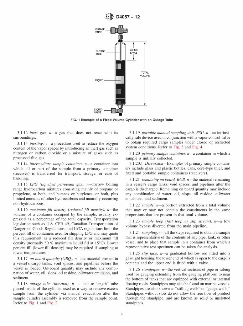
3.1.18 outage tube (internal), n—a “cut to length” tubeplaced inside of the cylinder used as a way to remove excesssample from the cylinder via manual evacuation after thesample cylinder assembly is removed from the sample point.Refer to Fig. 1 and Fig. 2.
3.1.19 portable manual sampling unit, PSU, n—an intrinsi-cally safe device used in conjunction with a vapor control valveto obtain required cargo samples under closed or restrictedsystem conditions. Refer to Fig. 3 and Fig. 4.
3.1.20 primary sample container, n—a container in which asample is initially collected.
3.1.20.1 Discussion—Examples of primary sample contain-ers include glass and plastic bottles, cans, core-type thief, andfixed and portable sample containers (receivers).
3.1.21 remaining on board, ROB, n—the material remainingin a vessel’s cargo tanks, void spaces, and pipelines after thecargo is discharged. Remaining on board quantity may includeany combination of water, oil, slops, oil residue, oil/wateremulsions, and sediment.
3.1.22 sample, n—a portion extracted from a total volumethat may or may not contain the constituents in the sameproportions that are present in that total volume.
3.1.23 sample loop (fast loop or slip stream), n—a lowvolume bypass diverted from the main pipeline.
3.1.24 sampling, v—all the steps required to obtain a samplethat is representative of the contents of any pipe, tank, or othervessel and to place that sample in a container from which arepresentative test specimen can be taken for analysis.
3.1.25 slip tube, n—a graduated hollow rod fitted into agas-tight housing, the lower end of which is open to the cargo’scontents and the upper end is fitted with a valve.
3.1.26 standpipes, n—the vertical sections of pipe or tubingused for gauging extending from the gauging platform to nearthe bottom of tanks that are equipped with external or internalfloating roofs. Standpipes may also be found on marine vessels.Standpipes are also known as “stilling wells” or “gauge wells.”Standpipes without slots do not allow the free flow of productthrough the standpipe, and are known as solid or unslottedstandpipes.
FIG. 1 Example of a Fixed Volume Cylinder with an Outage Tube
D4057 − 12
4

3.1.27 ullage (outage), n—the volume of available space ina container unoccupied by contents.
3.1.28 vapor control valve, VCV, n—a valve fitted on astandpipe, expansion trunk, or the deck that permits use of theportable handheld gauging/sampling instruments while re-stricting the release of vapors into the atmosphere.
3.1.29 vapor pressure, n—the pressure exerted by the vaporof a liquid when in equilibrium with the liquid.
3.1.29.1 Reid vapor pressure, RVP, n—resultant total pres-sure reading, corrected for measuring error, of a specific
empirical test method (Test Method D323) for measuring thevapor pressure of gasoline and other volatile products.
3.1.29.2 true vapor pressure, TVP, n—the pressure at whichthe fluid is in equilibrium between its liquid and gas state.
Sample Types
3.1.30 all-levels sample, n—a sample obtained by loweringthe closed sampling device to the bottom of the outlet suctionlevel, but always above free water, then opening the samplerand raising it at a uniform rate such that it is between 70 and
FIG. 2 Example of a Fixed Volume Cylinder and Transfer Line
FIG. 3 Examples of a Small Volume (5 cm (2 in.)) and a Large Volume PSU (10 cm (4 in.))
D4057 − 12
5

85 % full when withdrawn from the product. Alternatively,all-levels samples may be taken with samplers designed forfilling as they pass downward through the product.
3.1.30.1 Discussion—If required by the test method, thesampler may be greater than 85 % full when withdrawn but inno case shall it be completely full. In these cases, take specialhandling precautions to consider the hazards associated withproduct thermal expansion.
3.1.31 boring sample, n—a sample of the material containedin a barrel, case, bag, or cake that is obtained from the chipscreated by boring holes into the material with a ship auger.
3.1.32 bottom sample, n—a spot sample collected from thematerial at the bottom of the tank, container, or line at itslowest point. In practice, the term bottom sample has a varietyof meanings. As a result, it is recommended that the exactsampling location (for example 15 cm (6 in.) from the bottom)should be specified when using this term. See Fig. 5.
3.1.33 bottom water sample, n—a spot sample of free watertaken from beneath the petroleum contained in a ship or bargecompartment or a storage tank.
3.1.34 clearance sample, n—a spot sample taken with theinlet opening of the sampling device 10 cm (4 in.) (someregulatory agencies require 15 cm (6 in.)) below the bottom ofthe tank outlet. This term is normally associated with small(159 m3 (1000 barrels) or less) tanks, commonly referred to aslease tanks.
3.1.35 composite sample, n—a sample prepared by combin-ing a number of samples and treated as a single sample. Alsorefer to “tank composite sample,” “volumetric compositesample,” “deck composite sample,” and “multiple tank com-posite sample” definitions.
3.1.36 core sample, n—a sample of uniform cross-sectionalarea taken at a given height in a tank.
3.1.37 dead bottom sample, n—a sample obtained from thelowest accessible point in a tank. This is typically directly fromthe floor (or datum plate) of the shore tank or the bottom of thevessel compartment.
3.1.38 deck composite sample, n—a sample typically madeby compositing a portion of each sample obtained from allvessel compartments containing a particular product grade.
3.1.39 dipper sample, n—a sample obtained by placing adipper or other collecting vessel in the path of a free-flowingstream to collect a definite volume from the full cross sectionof the stream at regular time intervals for a constant time rateof flow or at time intervals varied in proportion to the flow rate.
3.1.40 drain sample, n—a sample obtained from the waterdraw-off valve on a storage tank vessel or container.Occasionally, a drain sample may be the same as a bottomsample (for example, in the case of a tank car).
3.1.41 floating roof sample, n—a spot sample taken justbelow the surface to determine the density (API gravity) of theliquid on which the roof is floating.
3.1.42 grab sample, n—(a) solid—a sample obtained bycollecting equal quantities from parts or packages of a ship-ment of loose solids so that the sample is representative of theentire shipment. (b) liquid—a sample collected at a specificlocation in a tank or from a flowing stream in a pipe at aspecific time.
FIG. 4 Examples of Closed/Restricted Sampling Equipment
FIG. 5 Illustration of Common Spot Sample Positions
D4057 − 12
6

3.1.43 grease sample, n—obtained by scooping or dipping aquantity of soft or semi-liquid material contained from apackage in a representative manner.
3.1.44 loading zone sample, n—a sample taken from a tankprior to commencement of a transfer, intended to representonly the product expected to be transferred.
3.1.45 lower sample, n—a spot sample of liquid from themiddle of the lower one-third of the tank’s content (a distanceof five-sixths of the depth liquid below the liquid’s surface).See Fig. 5.
3.1.46 middle sample, n—a spot sample taken from themiddle of a tank’s contents (a distance of one half of the depthof liquid below the liquid’s surface). See Fig. 5.
3.1.47 multiple tank composite sample, n—a mixture ofindividual samples or composites of samples that have beenobtained from several tanks or ship/barge compartments con-taining the same grade of material. The mixture is blendedtypically in proportion to the volume of material contained inthe respective tanks or compartments.
3.1.48 representative sample, n—a portion extracted fromthe total volume that contains the constituents in the sameproportions that are present in that total volume.
3.1.49 running sample, n—a sample obtained by loweringan open sampling device to the bottom of the outlet suctionlevel, but always above free water, and returning it to the topof the product at a uniform rate such that the sampling deviceis between 70 and 85 % full when withdrawn from the product.
3.1.49.1 Discussion—If required by the test method, thesampler may be greater than 85 % full when withdrawn but inno case shall it be completely full. In these cases, take specialhandling precautions to consider the hazards associated withproduct thermal expansion.
3.1.50 spot sample, n—a sample taken at a specific locationin a tank or from a flowing stream in a pipe at a specific time.
3.1.51 suction sample (outlet), n—a spot sample taken at thelowest level from which product is expected to be pumpedfrom the tank; see Fig. 5.
3.1.52 sump sample, n—spot sample taken from within thetank or vessel compartment sump; see Fig. 5.
3.1.53 surface sample (skim sample), n—a spot sampleskimmed from the surface of a liquid in a tank. See Fig. 5.
3.1.54 tank composite sample, n—a blend created from asingle tank, as an example combining the upper, middle, and
lower samples. For a tank of uniform cross section, such as anupright cylindrical tank, the blend consists of equal parts of thethree samples. A combination of other samples may also beused, such as running, all-levels or additional spot samples. Fora horizontal cylindrical tank, the blend consists of samples inthe proportions shown in Table 1.
3.1.55 tank tap sample, n—a spot sample taken from asample tap on the side of a tank. It may also be referred to asa tank-side sample.
3.1.56 test specimen, n—a representative sub-sample takenfrom the primary or intermediate sample container for analysis.
3.1.57 top sample, n—a spot sample obtained 15 cm (6 in.)below the top surface of the liquid. See Fig. 5.
3.1.58 tube sample (thief sample), n—a sample obtainedwith a sampling tube or special thief, either as a core sample orspot sample, from a specific point in the tank or container.
3.1.59 upper sample, n—a spot sample taken from themiddle of the upper one third of the tank’s contents (a distanceof one-sixth of the depth of the liquid below the liquid’ssurface). See Fig. 5.
3.1.60 volumetric composite sample, n—a sample consistingof measured proportional parts from each zone if it is for asingle tank. If the volumetric composite is for multiple tanks,or vessel compartments, it consists of measured proportionalparts from each tank or compartment sampled.
3.1.61 zone sample, n—a sample taken as that part of theliquid column that is trapped within the whole height of asampling device when it is sealed at a single spot locationwithin a tank after having been fully flushed as it was loweredto that position.
4. Significance and Use
4.1 Samples of petroleum and petroleum products are ob-tained for many reasons, including the determination of chemi-cal and physical properties. These properties may be used for:calculating standard volumes; establishing product value; andoften safety and regulatory reporting.
4.2 There are inherent limitations when performing any typeof sampling, any one of which may affect the representativenature of the sample. As examples, a spot sample provides asample from only one particular point in the tank, vesselcompartment, or pipeline. In the case of running or all-level
TABLE 1 Sampling from Horizontal Cylindrical Tanks
Liquid Depth (% of Diameter) Sampling Level (% of Diameter above Bottom) Composite Sample (Proportional Parts)
Upper Middle Lower Upper Middle Lower
100 80 50 20 3 4 390 75 50 20 3 4 380 70 50 20 2 5 370 ... 50 20 ... 6 460 ... 50 20 ... 5 550 ... 40 20 ... 4 640 ... ... 20 ... ... 1030 ... ... 15 ... ... 1020 ... ... 10 ... ... 1010 ... ... 5 ... ... 10
D4057 − 12
7

samples, the sample only represents the column of materialfrom which it was taken.
4.3 Based on the product, and testing to be performed, thispractice provides guidance on sampling equipment, containerpreparation, and manual sampling procedures for petroleumand petroleum products of a liquid, semi-liquid, or solid state,from the storage tanks, flowlines, pipelines, marine vessels,process vessels, drums, cans, tubes, bags, kettles, and opendischarge streams into the primary sample container.
5. Health and Safety Precautions
5.1 General—This practice does not purport to cover allsafety and health aspects associated with sampling. Personnelinvolved with sampling of petroleum and petroleum-relatedproducts should be familiar with their physical and chemicalcharacteristics, including: potential for fire, explosion, andreactivity; toxicity and health hazards; and appropriate emer-gency procedures. Additionally personnel should comply withindividual company safe operating practices and local, state,and national regulations, including the use of personal protec-tive equipment (PPE). Upon completion of any samplingactivity, ensure the sample point is left in a safe, secure, andclean condition with the handling of any waste in accordancewith local requirements. All marine vessel sampling should beperformed in the presence of a designated vessel representa-tive.
5.2 Sample Handling—For safety and protection of theintegrity of the samples, sample carriers are suggested in mostinstances. Refer to Fig. 6. Because of potential liquid thermalexpansion, sample containers that are completely, or nearlyfull, are not to be transported or stored, unless special precau-tionary measures are taken. A safe fill of between 70 and 85 %is recommended. Refer to definition for maximum fill densityand 9.30 for safe fill of pressurized cylinders. Take care toavoid heating samples in containers with gas-tight caps, lids,and stoppers. Handle any sample containing hazardous mate-rials or the residue of hazardous materials offered for shipment/transportation by air, public roadway, rail, or water in such a
manner as to ensure compliance with requirements such astraining, documentation, labeling, container, packaging,communications, and so forth, set forth in applicableregulations, such as those issued by the International AirTransport Association (IATA) and the U.S. Department ofTransportation (DOT).
5.3 Sample Point Safety:5.3.1 Provide sample points that enable samples to be taken
in a safe manner, considering ventilation during sampling,clear access/egress, and lighting. Any potential hazards asso-ciated with sampling, or located near the sample point, shouldbe clearly marked. It is recommended that a pressure gauge anda method of closed loop flushing with safe drainage, beprovided at pipeline sample points. Sample points and relatedequipment should be maintained and inspected regularly.
5.3.2 Floating-roof tanks should be sampled from the topplatform, thereby avoiding descent onto the floating roof.Descending onto a floating roof is normally considered enter-ing a designated confined space, requiring all facility andregulatory requirements to be strictly followed, includingobtaining a confined space permit, and rescue provisionsarranged. Toxic and flammable vapors may accumulate on theroof.
5.4 Static Electricity Hazards:5.4.1 A number of fires and explosions have occurred as a
result of hydrocarbon vapors being ignited by static electricity.If electrical charges are not earthed or grounded, they areunable to dissipate and become “static.” This static electriccharge can accumulate and freely migrate to a single point onthe sample container by a difference in electrical potential, thenjump off as a high-energy spark discharge to a nearby lesscharged surface, often hot and prolonged enough to ignitenearby hydrocarbon vapors above the lower explosive limit(LEL). This potential shall be managed by safely dissipatingstatic charges, and through proper grounding, when samplingflammable products.
5.4.2 Footwear or clothing, capable of causing sparks,should not to be worn during sampling activities in whichflammable vapors are likely to be present. Sampling should notbe carried out during periods of atmospheric electric distur-bance or hail storms. To ground any static charge on theirperson, the individual performing the sampling should touchpart of the tank structure at least 1 m (3 ft) from the samplepoint immediately before sampling.
5.4.3 Precautions are to be observed before sampling toreduce the likelihood of a static charge being present. Duringtank filling or mixing operations, and for 30 min after thecompletion, sampling equipment shall not be introduced into,or remain in, the tank. With full observance of applicableregulatory requirements, and only under very specific anddocumented conditions, some exceptions to the 30-min relax-ation period may apply. Some tanks and vessel compartmentshave inert gas blankets in the vapor space above the liquid.Unless the effectiveness of the inert blanket can be verified, allstatic charge precautions and recommendations should beobserved.
FIG. 6 Typical Sample Carrier
D4057 − 12
8

5.4.4 Exercise caution when using equipment made ofaluminum, magnesium, or titanium, which may generate in-cendiary sparks when struck against rusted steel. Some coun-tries restrict the use of sampling equipment made from suchmaterials or from alloys containing more than 15 % (m/m) intotal of these metals or 6 % (m/m) of magnesium.
5.5 Pipeline/Line Sampling—When sampling from a flow-ing pipeline, maintain electrical continuity between the pipe-line and the sample container via the connecting pipework. Donot use plastic containers since they are non-conductive andwill not dissipate static electricity. Use a static groundingclamp or other arrangement that ensures adequate electricalcontinuity is maintained if sampling with a metal container. Aneffective ground should be verified.
NOTE 1—The API safety publication Protection Against IgnitionsArising Out of Static, Lightning, and Stray Currents states that electricalresistances of higher than 10 in metal circuits are indicative of a break inthe continuity of the circuit, resulting in the undesirable accumulation ofstatic electricity.7
5.6 General Health Hazards and Precautions:5.6.1 Petroleum vapor dilutes oxygen in the air and may
also be toxic. Hydrogen sulfide vapors are particularly hazard-ous. Harmful vapors or oxygen deficiency cannot always bedetected by smell, visual inspection, or judgment. The use ofoxygen and toxic gas monitors, PPE, and emergency rescueprecautions should be considered for all sampling operations.Self-contained breathing apparatus (SCBA) may be necessary.Personnel should position themselves upwind of the samplepoint to minimize exposure to any harmful vapor which may bereleased.
5.6.2 This discussion on safety and health is not exhaustive.The appropriate Material Safety Data Sheet (MSDS), API, orASTM International publication should be consulted, togetherwith applicable regulatory requirements, and the InternationalSafety Guide for Oil Tankers and Terminals (ISGOTT),8 Safetyof Life at Sea (SOLAS),9 and Oil Companies InternationalMarine Forum (OCIMF),10 while always observing companyand local health and safety requirements.
6. Apparatus
6.1 General Sample Container Design Considerations:6.1.1 Sample containers come in a variety of shapes, sizes,
and materials. Select the proper container based on the productto be sampled to ensure that there will be no interactionbetween the product sampled and the container that wouldaffect the integrity of either. The following are general designconsiderations for sample containers:
6.1.1.1 No internal pockets or dead spots;6.1.1.2 Internal surfaces designed to minimize corrosion,
encrustation, and water/sediment clingage;
6.1.1.3 An inspection cover/closure of sufficient size tofacilitate filling, inspection, and cleaning;
6.1.1.4 Designed to allow the preparation, and transfer tothe analytical apparatus, of a homogeneous mixture of thesample while minimizing the loss of any constituents that affectthe representativeness of the sample and the accuracy of theanalytical tests.
6.1.2 Additional considerations in the selection of samplecontainers are the type of mixing required before transferringfrom the primary container, and the analysis to be performed.To facilitate the discussion on proper handling and mixing ofsamples, sample containers are referred to as either primary orintermediate containers. Regardless of the type of samplecontainer used, the sample container should be large enough tocontain the required sample volume and sufficient ullage spacefor thermal expansion and mixing of the sample.
6.1.3 While this practice is meant to provide some guidancerelated to particular products and tests, it remains the respon-sibility of the subcommittee for the relevant test method toprovide specific guidance regarding sample containerselection, preparation, cleanliness, and sample size require-ments for testing and retention. Also refer to Practice D5854(API MPMS Chapter 8.3), Practice D5842 (API MPMS Chap-ter 8.4), and Practice D4306.
6.2 Glass Bottles—See Fig. 7. Glass containers are suitablefor many sample test and storage requirements. Clear glassbottles can be easily examined visually for cleanliness, and
7 Protection Against Ignitions Arising Out of Static, Lightning, and StrayCurrents, Edition 7, American Petroleum Institute, Washington, DC, 2008.
8 International Safety Guide for Oil Tankers and Terminals (ISGOTT), HyperionBooks, 2006.
9 International Convention for the Safety of Life at Sea (SOLAS), InternationalMaritime Organization, London, UK, 1974.
10 Available from Oil Companies International Marine Forum (OCIMF), 29Queen Anne’s Gate, London SW1H 9BU, U.K., http://www.ocimf.com.
FIG. 7 Amber and Clear Boston Round Bottles
D4057 − 12
9

allow for visual inspection of the sample for haze (cloudiness),discoloration, free water, and solid impurities. The brown glassbottle affords some protection to the samples when light mayaffect the test results. Refer to Practice D5854 (API MPMSChapter 8.3).
6.3 Cans—When using cans, any seams shall have beensoldered on the exterior surfaces with a flux of rosin in asuitable solvent. Such a flux is easily removed with gasoline,whereas many others are very difficult to remove. Cans madeof stainless steel with welded seams, and aluminum bottles, aresuitable for many sampling operations, but cleanliness is stillrequired. Minute traces of flux may contaminate the sample sothat results obtained on tests such as dielectric strength,oxidation resistance, and sludge formation may be erroneous.For aviation fuel sampling, refer to Practice D4306.
6.4 Plastic Bottles—In general, plastic bottles made ofsuitable material may be used for the handling and storage ofdiesel oil, fuel oil, and lubricating oil. Bottles of this typeshould not be used for gasoline, aviation jet fuel, kerosene,crude oil, white spirit, medicinal white oil, or other petroleumproducts unless testing indicates there is no problem withsolubility, contamination, or loss of light components. In nocircumstances shall nonlinear (conventional) polyethylenecontainers be used to store samples of liquid hydrocarbons.This is to avoid sample contamination or sample bottle failure.Used engine oil samples that may have been subjected to fueldilution should not be stored in plastic containers. Plasticbottles do have an advantage in that they will not shatter likeglass or corrode like metal containers.
6.5 Container Closures:6.5.1 Screw caps made of a material that will not deteriorate
or contaminate the sample are to be used for glass bottles.Screw caps should provide a vapor-tight seal. Use care whenusing cork stoppers. Situations in which corks should not beused include: liquids in which loss of light ends may affect anytest results; and liquids that are hygroscopic or have alow-water content specification. Rubber stoppers are not to beused.
6.5.2 Cans and plastic bottles should be closed with screwcaps made of the same material as the container. Protect canscrew caps with a disk faced with a material that will notdeteriorate or contaminate the sample when used to store ortransport samples. Consideration of closure type is importantfor samples in which vapor loss will affect the test results.Screw caps of a quality that provide a vapor-tight closureshould be used for plastic bottles and cans. Use screw caps forcontainers used to take samples that will be tested for densityor API gravity.
6.6 Container Cleanliness—Sample containers shall beclean and free from all substances that might contaminate theproduct being sampled (such as water, dirt, lint, washingcompounds, naphtha and other solvents, soldering fluxes,acids, rust, and oil). Reusable containers shall be cleaned by amethod that has been determined as acceptable for the intendeduse, for example by rinsing with a suitable solvent. Dry thecontainer, for example either by passing a current of cleanwarm air through the container or placing it in a hot, dust-free
cabinet at 40°C (104°F) or higher. When dry, stopper or cap thecontainer. Normally, it is not necessary to wash new containers.
6.7 Container Compatibility for Sample Mixing—Thesample container should be compatible with the mixing systemfor remixing samples to ensure that a homogenous sample istransferred to an intermediate container or the analyticalapparatus. This is particularly critical with crude oil, someblack products, and condensates for sediment and water (S &W) analysis. Cylindrical containers are generally better suitedfor samples that are to be tested for S & W. Refer to PracticeD5854 (API MPMS Chapter 8.3) for sample mixing andhandling requirements.
6.8 Low Pressure Variable Volume Containers—Low pres-sure variable volume sample container designs include collaps-ible plastics containers, bladders, and vessels fitted with aflexible internal diaphragm. Before use, variable volumesample containers are normally collapsed, evacuated or re-duced to the nominal zero volume. The sample container sizeis dependent on the quantity required for analysis (and/orretention). Prior to use, it may be appropriate to rinse thesample containers with the product being sampled, in order toavoid contamination from previous sample residue and/orsolvents used to clean the low pressure variable volumecontainers. The sample should be transported to the laboratoryin the container in which it was originally obtained (theprimary sample container). Plastics containers are not recom-mended for long-term sample storage, unless it has beendemonstrated that the plastic is suitable (that is, compatiblewith the sample) so that the integrity of the sample is notcompromised. (Warning—The use of containers made ofnon-linear polyethylene may lead to sample contaminationand/or sample container failure.)
6.9 High Pressure Spot Sampling Systems and Cylinders:6.9.1 Sample System Components—All equipment, such as
transfer lines, valves and pressure gages, associated withsampling shall be corrosion resistant and designed consistentwith the maximum anticipated pressure. Experience has shownthat the transfer lines should have a minimum internal diameterof 3 mm (1⁄8 in.) nominal and be as short as practical tominimize line blockage or sample vaporization, or both. Theuse of filters, dryers, needle valves and related equipment arenot recommended, unless provisions are made to preventexcessive flow restriction and pressure drop. It is recom-mended to use a “T” junction with a purge valve at the sampleconnection point to allow purging of the dead volume at thesampler connection. Flexible hose or tubing with adequatepressure rating may be used.
6.9.2 Cylinders—High pressure cylinders are used for thecollection of light liquid hydrocarbons and gas samples andsubsequent transportation and storage. Typical light liquidhydrocarbon sample containers are fixed volume cylinders orfloating-piston cylinders (FPCs). Refer to Practices D1265,D3700, and D6849.
Fixed Volume Cylinder6.9.2.1 Fixed volume sample cylinders are also known as
single cavity sample cylinders or spun cylinders. Refer to Fig.1 and Fig. 2.
D4057 − 12
10

6.9.2.2 Valves—Fixed volume sample cylinders are typi-cally available with either one or two valves serving as cylinderinlet and outlet valves. Recommend using two-valve fixedvolume sample cylinders due to their ease of cleaning andpurging prior to sampling. For repeated use, it is recommendedthat one-valve fixed volume sample cylinders be used for onlyone product, due to difficulty in cleaning.
6.9.2.3 Internal Outage (Ullage) Tubes—It is recommendthat fixed volume cylinders be equipped with an internal outage(ullage) tube, designed to provide a vapor space of typically20 % of the cylinder capacity, allowing for liquid thermalexpansion. The end of the cylinder fitted with the outage(ullage) tube shall be clearly marked. If the cylinder does nothave an internal outage (ullage) tube, use alternative purgingand venting procedures to obtain a minimum 20 % ullage in thecylinder. An internal outage tube within a fixed volume samplecylinder may also be known as an ullage tube or dip tube.
Sample Cylinder Usage Considerations6.9.2.4 The type of sample cylinder used and its materials of
construction as well as hoses and fittings can affect the validityof the sample, as well as the accuracy of the analysis.
6.9.2.5 When the observed vapor pressure of the liquidbeing sampled is close to the line pressure, the reduction insample pressure associated with the creation of the ullage spacemay result in phase separation that can make subsequentrepresentative sub-sampling difficult. In these circumstances,an FPC should be used to ensure that the sample is maintainedat sufficient pressure to prevent phase separation.
6.9.2.6 Where small concentrations of contaminants need tobe quantified or where concentrations of volatile compoundsother than the predominant component need to be quantified,an FPC is recommended.
NOTE 2—Practice D3700 describes a recommended practice for obtain-ing a representative sample of a light hydrocarbon fluid and the subse-quent preparation of that sample for laboratory analysis when dissolvedgases are present. Use of Practice D1265 using a fixed volume cylinder,will result in a small but predictable low bias for dissolved gases due tothe liquid venting procedure to establish the 20 % minimum ullage.
6.9.2.7 Cylinder Construction—Cylinder construction isprimarily dependent on the pressure and temperature of theproduct to be sampled, and the pressure vessel approval and
certification requirements in the jurisdictions in which it is tobe used and transported. All sample cylinder material, andequipment used for obtaining the sample, shall meet appropri-ate standards for construction, cleanliness and suitability foruse, including product compatibility. Use corrosion resistantmetal sample cylinders certified by the authority havingjurisdiction for pressure vessels with adequate pressure ratingfor the product being sampled. Common materials used arenon-magnetic 300-series stainless steel, Monel(trademarked),11 Viton elastomeric components, and possiblyother materials. The size of the cylinder depends upon theamount of sample required to perform the anticipated labora-tory tests, and to be retained. Blanking cover caps may beprovided to seal the valve connection points of high pressuresample cylinders prior to their transportation between thesampling location and the laboratory.
Floating Piston Cylinders (FPC)6.9.2.8 FPC, also known as a variable-volume cylinder or
pressure-balanced piston cylinder, can be used to sample pureand multi-component liquids and when properly operated,maintains the sample as a single-phase liquid. This device usesone, or two pistons, inside of the sample cylinder to maintainseparation between the liquid sampled and the backpressureinert gas. The two-piston cylinder is known as the double-piston cylinder (DPC). The inert gas is vented slowly to allowthe sample to enter the cylinder while maintaining a constantpressure on the sample. FPCs are typically constructed from ahoned metal tube equipped with end caps, valves, piston, arelief device to protect against over-pressure, and a method ofdisplaying the piston position. See Fig. 8, Fig. 9, and Fig. 10.
6.9.2.9 Refrigerated Products—The FPC shall be safelycooled to the temperature of the product being sampled whensampling refrigerated liquids that are near or below atmo-spheric pressure. Low cargo temperature (more than approxi-mately 15°C below ambient) and low cargo pressure (nearatmospheric pressure) may affect the ability of the user tosuccessfully capture a representative liquid sample using an
11 Monel is a trademark of Special Metals Corporation.
FIG. 8 Example of Single Floating Piston (Variable Volume) Cylinder (FPC)
D4057 − 12
11

FPC if additional care is not taken; and the use of a vacuumpump may be required. Refer to Practice D3700 and GPA S2174.
6.9.2.10 Piston Position Indicator—The FPC shall beequipped with a piston position indicator such as a magneticfollower, piston rod, or equivalent that is used to indicate thesample volume to comply with the maximum percent fill(maximum fill density) allowed for storage and transportation.Do not use FPCs that are not equipped with a piston positionindicator without a procedure to allow the operator to verify fill
density immediately after sampling prior to transport. Consultthe authority having jurisdiction for acceptable procedures. SeeFig. 8 and Fig. 9.
6.9.2.11 Lubricants—Lubricants used to lubricate or seal thefloating piston, O ring seals, and other components shall beinert to the product being sampled.
6.9.2.12 Cylinder Coatings—Some cylinders may be inter-nally coated or lined to reduce the chances of bare metalsurfaces reacting with trace reactive components, potentiallyaltering the quality and integrity of the sample. For example, be
FIG. 9 Example of Single Floating Piston (Variable Volume) Cylinder (FPC)
FIG. 10 Example of Single Floating Piston (Variable Volume) Cylinder (FPC)
D4057 − 12
12

absorbed into the structure of 316 stainless steel, so that testingfor H2S may require the cylinder to be coated. Protectiveinternal coatings or surface treatments are acceptable for FPCsprovided that they do not adversely affect the free movement ofthe piston, or effectiveness of the seals.
Cylinder Pressure Relief6.9.2.13 Fit a ruptured disk or a self-resetting pressure relief
valve to the cylinder to prevent overpressure as the result ofliquid thermal expansion. It is recommended to use a springrelief valves if self-resetting is required. Typically, the maxi-mum operating system pressure should be limited to 80 % ofthe nominal rating of the rupture disk for static operatingpressure and ambient temperature. The relief maximum burstpressure shall not exceed the cylinder test pressure. Refer toapplicable regulatory requirements for safe filling limits.
6.9.2.14 Cylinder Pressure Relief Inspection—The strengthof rupture disks can deteriorate with time due to temperature,corrosion, and fatigue. In addition, pulsating pressure, vacuum/pressure cycling, heat, and corrosive fluids and atmospherescan reduce the disk’s burst pressure. Relief valves and rupturedisks should be inspected regularly. Do not alter valves orsafety relief devices that are part of a cylinder permit orexemption.
NOTE 3—The USA has an exemption system, and Canada has apermitting procedure for non-American Society of Mechanical Engineers(ASME) or Department of Transportation (DOT) cylinders.
6.9.2.15 Cylinder Pressure Relief Release—The suddenrelease, typically accompanied by a loud noise and productreleased at high velocity, might create a hazard. If the samplecylinder pressure exceeds the relief device setting and part ofthe sample cylinder contents are vented, the composition of theremaining sample is likely different from the original contents.Another sample should be drawn and procedures revised toavoid the circumstances that led to the overpressure condition.
6.9.3 Cylinder Approval and Rating—If the cylinder is to betransported, it shall also conform to specifications published in
transportation legislation such as U.S. CFR 49 or CanadianTransportation of Dangerous Goods Regulations, and theirsupplements, reissues, or similar regulations in other jurisdic-tions.
6.9.4 Cylinder Extreme Temperature Considerations—Forsafe handling of cylinders under extremes of product orambient temperatures, or both, the user shall consider theeffects of thermal expansion on the volume of product in thecylinder. For example, if a very cold (e.g. – 40°C (–40°F))product is sampled, the cylinder should be expected to warmconsiderably before analysis is performed during transport andin the laboratory. During summer months, the temperature ofthe cylinder and product could reasonably be expected to riseto as high as 46°C (115°F) in hot environments. A cylinderinitially filled to 80 % of its capacity will be over pressured andthe relief device(s) will activate under these conditions. In suchan extreme but not uncommon case the cylinder should not befilled more than approximately 60 % during the initial fill. Theappropriate industry volume correction factor data and calcu-lations should be consulted to determine the maximum fill forthe product being sampled. It is recommended that users workwith the manufacturer of these sample cylinders and samplecollection systems any time ambient or product temperatures,or both, exceed the range of –29°C (–20°F) to 60°C (140°F).Consider the effects of extreme temperature on metal, O-rings,valve seats, seals, gauges, relief devices, sample pump com-ponents and other devices and components in the system.
6.9.5 Mixing Capability—The cylinder may include amechanism to mix the sample in the sample chamber in case ofstratified mixtures or water haze that may settle after sampling.This mechanism may be a mechanical mixer/vortex plate on amovable rod, a freely moving rolling ball or slider, magneti-cally coupled stirrer, or similar device. Some designs of FPCshave two pistons, which enable the sample to be mixed withinthe cylinder (prior to sub-sampling) by repeatedly forcing itthrough a central mixing device. See Fig. 9 and Fig. 11.
FIG. 11 Example of Typical High-Pressure Sampling System
D4057 − 12
13
6.9.6 Sample Cylinder Cleanliness—To ensure the samplecylinder and its components do not affect the integrity andquality of the sample obtained, the user shall establish anacceptable cylinder cleaning and preparation process based onexperience, and considering the following factors:
(1) Type of cylinder and design,(2) Cylinder material and lining,(3) Cylinder components (valves, seals, etc.) and attached
tubing/lines,(4) Recent history of the cylinder, including repair or last
product,(5) Product being sampled,(6) Product test methods,(7) Purity of product being sampled, and concern with trace
contaminants, and(8) Use of cleaning agents.
6.9.6.1 Sample Cylinder Cleaning and Purging Methods—Based on the above factors any one, or combination, of thefollowing may be deemed as satisfactory cylinder cleaningmethods:
(1) Purging and flushing of the cylinder using a cleaningagent or solvent, for example acetone or methanol. It isrecommended to purge and flush the sample cylinder at leastthree times.
(2) Purging and flushing of the cylinder using an inert gas,such as helium and nitrogen. Testing of the inert gas present inthe cylinder is recommended to confirm no trace of hydrocar-bon gas or impurities. It is recommended to purge and flush thesample cylinder at least three times.
(3) Purging and flushing of the cylinder using the productbeing sampled. It is recommended to purge and flush thesample cylinder at least three times.
(4) Steam (not recommended for floating piston cylinders).(5) Warming and drying of cylinders.(6) Manufacturer’s recommendations.
6.9.6.2 Cylinders used in continuous service, for examplewith specification LPG products or stabilized crude, may notrequire disassembly or cleaning before each use. For example,it may be acceptable to vent the previous product as a liquid,and remove remaining sample from dead volume by solventrinsing, evacuation, gas purge, or equivalent procedure.(Warning—Disassembly of the piston cylinder for mainte-nance requires special precautions. If either end cap is removedwhile pressure is on the cylinder, the end caps and the pistoncan be ejected with such a force as to cause serious injury topersonnel and damage to equipment. Consult the manufactur-er’s instructions, and regulatory guidelines, for the mainte-nance and safe disassembly instructions for all cylinders.)Refer to Practice D6849.
6.10 Special Sample Cylinders—Specially designed singlepurpose sample cylinders are often used for non-compositionaltests, the testing of trace constituents using specificinstruments, and physical property testing devices. Refer toTest Method D1838, Test Method D1267, API MPMS 14.6,and Test Method D1657 (API MPMS Chapter 9.2) for details.In addition, spot samples may be tested for some components,including trace analysis using length-of-stain tubes, gas contentusing lower explosive limit or gas detectors, oxygen content
using oxygen detectors and trace oxygen analyzers, and mois-ture content using dew point instruments. Refer to manufac-turer’s instructions and appropriate industry standards for useand applicability.
7. Sampling Devices/Equipment and Accessories
Introduction
7.1 The preferred manual sampling devices and processesare those that do not require the sample to be transferred fromthe primary sample container to an intermediate container.Sampling devices shall be designed, constructed, and main-tained to ensure that they perform the purpose or function forwhich they are intended. They shall be of sufficient strength towithstand pressures likely to be generated and sufficientlyrobust to withstand normal handling. Liquid sampling devicesshall be leak-tight to maintain the initial characteristics of thesample. Materials of construction for sampling devices andtheir accessories should be compatible with the productsampled and ensure that there will be no interaction betweenthe product and the sampling device that would affect theintegrity of either.
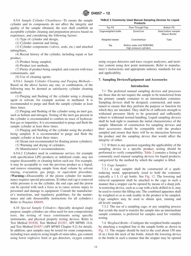
7.2 If there is any question regarding the applicability of thesampling device to a specific product, testing should beperformed to verify compatibility. Table 2 contains a listing ofcommonly used manual sampling devices for liquid products;categorized by the method by which the sampler is filled.
7.3 Cage Sampler:7.3.1 A cage sampler shall be constructed of a spark-
reducing metal, appropriately sized to hold the container,typically a 1 L (1 qt) bottle. See Fig. 12. The lowering andretrieval equipment shall be attached to the cage in such amanner that a stopper can be opened by means of a sharp jerk.A restricting device, such as a cap with a hole drilled in it, maybe used to restrict the filling rate. The combined apparatus shallbe weighted so as to sink readily in the product to be sampled.Cage samplers may be used to obtain spot, running andall-levels samples.
7.3.2 The use of a sampling cage, or any sampling processthat avoids the need to transfer the sample into an intermediatesample container, is preferred for samples used for volatilitytesting.
7.4 Weighted Bottle—Configure the weighted bottle samplerby attaching a weighted line to the sample bottle as shown inFig. 13. The stopper should be tied to the cord about 150 mm(6 in.) from the neck of the bottle. Attach the lowering deviceto the bottle in such a manner that the stopper may be opened
TABLE 2 Commonly Used Manual Sampling Devices for LiquidProducts
Top Fill Flow Through/Trap Bottom Fill
Cage/weighted bottle Zone/Core Dead bottom sampler(Bacon Bomb)
Weighted beaker Core/interface Tube
Tap Bottom water and ROB/OBQHigh pressure cylinders
D4057 − 12
14

by means of a sharp jerk of the lowering cord. A restrictingdevice, such as a cap with a hole drilled in it, may be used torestrict the filling rate. Weight the combined apparatus so as tosink readily in the product to be sampled. Design shall allow
for filling the container at any desired level. A weighted bottlesampler may be used to obtain spot, running, and all-levelssamples.
FIG. 12 Cage Samplers
FIG. 13 Weighted Bottle
D4057 − 12
15

7.5 Weighted Beaker—The sampling beaker shall be con-structed of a spark-reducing metal and weighted so as to sinkreadily in the liquid to be sampled. The lowering and retrievalequipment shall be attached to the sampler in such a mannerthat a stopper can be opened by means of a sharp jerk. Toreduce the difficulty with cleaning the beaker, any weightingmaterial shall be fixed to the beaker in such a way that it doesnot come into contact with the sample. Weighted beakersampler may be used to obtain spot, running, and all-levelssamples. Caution shall be exercised to ensure that a residuefrom prior samplings does not contaminate subsequent samplesobtained. Samples obtained using a weighted beaker requirestransfer to an intermediate container, potentially affecting theintegrity of the sample. See Fig. 14.
7.6 Bottom Water and Remaining On-Board/On-BoardQuantity (ROB/OBQ) Sampler/Scraper—Typically constructedof copper or brass tubing, open at the top, designed with a clipon one side, and rounded bottom to allow the sampler to tipover on the tank or vessel compartment bottom. This devicemay have a removable bottom for cleaning. Sampler fills withproduct at first, hits the bottom, and falls over. Product rises tothe top with free water displacing the product in the sampler.
Use the sampler/scraper in a similar manner to sample verysmall volumes in a tank or OBQ/ROB product on marinevessels including, sludge and semi-liquid or high-viscositymaterial residue. See Fig. 15.
7.7 Tank Tap Sampling:7.7.1 Each tap should be a minimum of 1.25 cm (1⁄2 in.) in
diameter. Taps with a 2.0 cm (3⁄4 in.) diameter or more may berequired for heavy, viscous liquids, for example, those with arelative density of 0.9465 or greater (18.0° API or less). Ontanks that are not equipped with floating roofs, each sample tapshould extend into the tank a minimum of 10 cm (4 in.). Somesample taps may be equipped with a delivery tube that permitsthe filling of the sample container from the bottom, as reflectedin Fig. 16. Refer to Practice D5842 (API MPMS Chapter 8.4).
7.7.2 Tap Sampling Requirements—At a minimum, a tankshould be equipped with a sample tap that is at the elevation ofthe main tank outlet. For multiple level samples, the tank is tobe equipped with at least three sampling taps placed equidistantthroughout the tank height, based on normal liquid heightoperating levels of the tank. Additional sample taps, forexample as many as a total of five or six, may be requiredbased on the size of the tank, type of product service,
FIG. 14 Weighted Beakers
D4057 − 12
16

anticipated varying liquid height operating levels, and historyof product homogeneity. With reference to the circumferentiallocation, sample taps should be located a minimum of 2.4 m(8 ft) from the tank inlet and 1.6 m (5 ft) from the tankoutlet/drain. If a tube is used, take steps to ensure that the tubewill not contaminate the product being sampled.
7.8 Pipeline Manual Tap Sample Probe:7.8.1 A sample probe in a pipeline is used to direct sample
from the flowing stream. Manual tap sample probes are oftenused for product identification, testing, and calibration ofonline instrumentation.
7.8.2 Probe designs that are commonly used are shown inFig. 17 and described in the following:
7.8.2.1 Fig. 17A—A tube beveled at a 45° angle;7.8.2.2 Fig. 17B—A short radius elbow or pipe bend.
Chamfer the probe end on the inside diameter to give sharpentrance edge; and
7.8.2.3 Fig. 17C and Fig. 17D—A closed-end tube with around orifice spaced near, but not at, the closed end.
7.8.3 Pipeline Manual Tap—Free Water/HazeVerification—If the sample system is designed such that thesample point on the pipeline is primarily intended to ascertainthe presence of water possibly riding the bottom of the pipe ata particular point, or intended to detect possible particulatecontamination, for example, such as pipeline origin and deliv-ery points and pump stations, the sample point may be installedsuch that the sample is drawn directly from the bottom of thepipe using no internal probe.
7.9 Pipeline Sampler and Probe Location:7.9.1 Since the product to be sampled may not always be
homogeneous, the location, position, and size of the sampleprobe should minimize any separation of water and heavierparticles that would make their concentration different in thegathered sample than in the main stream. It is recommendedthat the probe be in a horizontal plane to prevent drain back ofany part of the sample to the main stream and located in anupward flowing vertical run of pipe. The probe may also belocated in a horizontal run of pipe. Extend the sample probeinto the center third of the pipe with the inlet facing up stream.The flowing product at the point of sampling should beadequately mixed. This can be accomplished from the normalflowing turbulent velocity, together with an in-line static mixer;typically either a series of baffles or a perforated plate. If theline is not equipped with a static mixer, it is recommended to
locate the sample point for spot samples just downstream fromcommon line equipment that may facilitate mixing, such as 45°elbows, control valves, manifolds, strainer baskets, meters, andprovers. If using the sample point for custody transferpurposes, refer to requirements as listed in Practice D4177(API MPMS Chapter 8.2).
7.9.2 Sample lines, used in conjunction with probes, shouldbe as short as practical and purged before each sample is taken,to avoid sample contamination.
7.9.3 When sampling heated or high-viscosity liquids, itmay be necessary to heat the sample line, valves, and samplecontainer to a temperature sufficient to keep the product in aliquid state to ensure accurate sampling. To control the rate atwhich the sample is withdrawn, the probe should be fitted withvalves or plug cocks. Extreme caution should be exercised atall times because of the higher probability of line plugs as aresult of solidified product.
7.10 Zone Sampler (Core Sampler):7.10.1 A zone sampler, also known as a core sampler or a
core–type sampling thief, shall be designed and constructedsuch that, when lowered slowly, it is capable of trapping avertical column of liquid at any selected level below thesurface to within 2.0 to 2.5 cm (3⁄4 to 1 in.) of the bottom of thetank. A zone sampler shall consist of a tube made of spark-reducing metal, glass, or plastic material open at both ends toallow free flow of liquid through the sampler during lowering.See Fig. 18 and Fig. 19.
7.11 The closing of the lower end of the tube to trap thesample at the desired level may be achieved by various meansincluding, but not limited to, the following:
7.11.1 A closure mechanism actuated by an extension rod orsharp jerk on the cord;
7.11.2 Simply raising the sampler causing the top andbottom flap valve to close;
7.11.3 A weight falling down a suspending cable to actuatethe closure mechanism, and;
7.11.4 The zone sampler shall be capable of penetrating theproduct in the tank and being withdrawn without unduecontamination of the contents.
7.12 A zone sampler (see Fig. 18) may include the followingfeatures:
7.12.1 Extension rods for use in obtaining samples at levelscorresponding with requirements for high-outlet connections orsamples to determine high settled sediment and water levels;
7.12.2 Sample cocks for determining the height of sedimentand water in the sampler core, as well as to place the sampledirectly into the testing apparatus. Refer to MPMS Chapter18.1;
7.12.3 A clear cylinder that facilitates observing the gravityand temperature of the oil during a gravity test;
7.12.4 A cord marked so that the sample can be taken at anydepth in the vertical cross section of the tank; and
7.12.5 A hook to hang the sampler in the hatch vertically.
7.13 Dead Bottom Sampler—Dead bottom samplers, suchas bacon bombs, normally have a projecting stem that opensthe inlet valve as the stem strikes the bottom of the tank. Thesample enters the sampler through the bottom valve and air is
FIG. 15 Example of Bottom Water and ROB/OBQ Sampler/Scraper
D4057 − 12
17

released simultaneously through the top valve. The inlet valveautomatically closes when the sampler is withdrawn. See Fig.20. The dead bottom sampler can also be equipped withextension rods, typically 7.6 cm (3 in.), 15 cm (6 in.), and 30.5cm (12 in.) to obtain samples from those points in a tank.
7.14 Tube Sampler—Drum or Barrel—Tube samplers areapplicable for sampling liquids and semi-liquids in drums,barrels and cans. The tube is made of glass, plastic, or metaland is designed so that it will reach to within approximately 3mm (1⁄8 in.) of the bottom of the container. The capacity of thetube can vary from 500 mL (1 pint) to 1 L (1 qt). A metal tubesuitable for sampling 189-L (50 gal) drums is shown in Fig. 21.Two rings soldered to opposite sides of the tube at the upperend are convenient for holding it by slipping two fingersthrough the rings, thus leaving the thumb free to close theopening.
7.15 Dipper/Ladle Sampler—The dipper will typically havea flared bowl and a handle of conventional length made ofmaterial such as tinned steel that will not affect the productbeing tested. The dipper shall have a capacity suitable for theamount to be collected and be protected from dust and dirtwhen not being used.
7.16 Auger Sampler—The auger sampler is applicable forsampling waxes and soft solids in drums, cases, bags, andcakes when they cannot be melted and sampled as liquids. Theauger should be 2 cm (3⁄4 in.) in diameter (preferred), similar tothat shown in Fig. 22, and of sufficient length to pass throughthe material to be sampled.
7.17 Pail and Scoop Sampler—Pail and scoop (grab) sam-pling is applicable for all lumpy solids in bins, bunkers, freightcars, drums, bags, boxes, and conveyors.
7.18 Accessory Equipment—Ropes, chains, and cables,which could be on a reel, are used to raise and lower samplingdevices. This equipment shall be clean ensuring that no residuefrom previous use contaminates the sample being taken. Do notleave samplers suspended in a tank when not in use, aselectrical continuity (bonding) may be lacking. While Section5 provides some guidance regarding conductivity andsafeguards, there may be specific and unique requirements withregard to conductivity, grounding, and bonding of somesampling equipment. Refer to the manufacturer’s instructionsand facility and regulatory requirements for such guidance.
7.18.1 Rope—Do not use ropes made of synthetic fibers.They shall be made of cotton or other non-static generating
FIG. 16 Tank Sample Taps
FIG. 17 Probe Designs
D4057 − 12
18

material and should include some means of determining thelevel of insertion into the tank or vessel. The rope may have aswivel clasp to link with the attached sample device designedto minimize twisting.
7.18.2 Chain—Chains shall be made of brass or otherspark-reducing material. The chain should have a swivel claspto link with the attached sample device designed to minimizetwisting. Caution should be exercised using chains becauseelectrical continuity cannot be guaranteed.
7.18.3 Cable—Cables shall be made of spark-reducing ma-terial. The cables shall have a swivel clasp to link with theattached sample device designed to minimize twisting.
7.18.4 Rod—Used primarily for shallow-depth samplingsuch as with truck and rail cars. It consists of a bottle cageattached to the end of a rigid pole or rod made fromspark-reducing material.
7.18.5 Bonding Cable—Conductive cable used to provideelectrical continuity between the sampling device, funnel,and/or primary container and a suitable ground point.
7.18.6 Retail Dispenser Nozzle Adapter—A nozzle extender,made from spark-reducing material, is designed to be fittedonto the end of a gasoline or diesel fuel nozzle. The adapter isequipped with a delivery tube that permits filling of the samplecontainer from the bottom. See Fig. 23.
7.18.7 Other Equipment—A funnel may be used to transferproduct from the sampling device to intermediate samplecontainers. Also, a graduated cylinder or other measuringdevice of suitable capacity is often required for determiningsample quantity in many of the sampling procedures and forcompositing samples. All accessory equipment used shall beclean, and not affect the integrity of the samples obtained.
8. Manual Sampling Concepts and Objective
8.1 Objective of Manual Sampling—The objective ofmanual sampling varies. In some instances, the intention is toobtain a small portion of product that is representative of thetank or container contents. In other instances, samples arespecifically intended to represent product only at that oneparticular point in the tank, such as a top, dead bottom, orsuction level sample. When a tank is determined to behomogenous, a series of spot samples may be combined tocreate a composite sample. Precautions should be taken tomaintain the integrity of the sample by preventing it from beingcontaminated by the sample point, the sample apparatus andequipment, the cleanliness of the container, the weather, andsample transfer operations. Manual sampling may be applied
FIG. 18 Example of Core/Interface Samplers—Thief
D4057 − 12
19

FIG. 19 Example of Core/Zone Samplers
FIG. 20 Example of Dead Bottom Samplers
D4057 − 12
20

under all conditions described in this practice. Alternativesampling procedures may be used as agreed upon by allinterested parties.
8.2 Training—Personnel shall be trained for the sampling tobe performed, including topics such as sample integrity, safety,and special handling related to specific tests.
8.3 Physical and Chemical Property Tests:8.3.1 The sampling procedure, sample container, quantity
required, and sample handling requirements will be based onthe test(s) to be performed, sample instructions related to acustody transfer and sample retention requirements.
8.3.2 In many liquid manual sampling applications, theproduct to be sampled contains a heavy component (such asfree water) that tends to separate from the main component. Inthese instances, it should be recognized that sampling willlikely result in varying sample quality until such time as theheavy component completely settles out. This period couldrange from only a few minutes to several weeks based on, butnot limited to, the product, temperature, agitation and the useof chemical additives.
9. Sampling Requirements, Considerations, andProcedures
9.1 General—This section provides requirements, recom-mendations and procedures for sampling preparation,sampling, and sample handling. More than one samplingmethod may provide satisfactory samples. A summary of themanual sampling procedures and their applications is presentedin Table 3.
9.2 Sampling Requirements and Considerations:9.2.1 Sample Request—The sampling process is often initi-
ated with a sample request. The request should provide
FIG. 21 Tube Sampler
FIG. 22 Auger Sampler
FIG. 23 Example of Nozzle Extender
D4057 − 12
21

adequate details and information necessary to establish thesample procedure, device, container, sample quantity, andsample handling. To assess sampling requirements, the follow-ing information should be established:
(1) Requestor contact information;(2) Date of request and required timeline;(3) Batch/job/vessel/voyage number;(4) Product description—Applicable safety data sheet
(MSDS) and Department of Transportation (DOT) informationshould be provided or available;
(5) Product location, tank or vessel number(s), and vol-ume(s);
(6) Test name(s) and method(s), and;(7) Special handling requests or precautions, such as split-
ting of samples, additional retention requirements, or suspectedproduct stratification. In some cases, a test method may requirea special container, a minimum amount of sample, or a specialsample handling procedure. At times, multiple test methodsmay have conflicting requirements, such as volatility testingand homogenizing for S & W. In these instances, it may benecessary to obtain separate samples for each test.
9.2.2 Equipment and Sample Container Preparation—Useonly sampling equipment and containers that are resistant tosolvent action by the product handled. Inspect all samplingequipment, including container, caps, lids, and stoppers toensure that they are clean and dry. Any residual material left in
a sampling device or sample container may contaminate thesample. It is recommended to rinse the sample container andequipment with the product to be sampled before drawingsamples.
9.2.3 Sample Transfers and Handling Requirements:9.2.3.1 The number of transfers from the primary container
to intermediate sample containers and the testing apparatusshould be minimized to maintain the product integrity andrepresentation. Common areas of concern related to transfersinclude loss of light ends, water, and heavy componentdisparities and possible residue contamination. Some of thetests affected might include, but are not limited to, flash point,vapor pressure (RVP), density, S & W, product clarity, ash,trace metals, and micro-separometer (MSEP).
9.2.3.2 Each time a sample is transferred, including to thetest apparatus, the sample should be completely mixed toensure it is homogenized, unless the specific test methodallows or specifies otherwise. The transfer should be completedduring the period that the sample remains homogenous. Theremay be specific practices that allow or specify the sample beingplaced directly into the test apparatus, such as from the thiefvia petcock into the centrifuge tube for small crude gatheringtanks. Refer to API MPMS Chapter 18.1.
9.2.4 Requirements for Mixing and Compositing IndividualSamples:
TABLE 3 Typical Sampling Procedures and Applicability
Application Type of Containment/Vessel/Tank Procedure
Petroleum liquids Storage tanks, tank cars, tank trucks Bottle samplingZone/Core samplingTap samplingHigh pressure cylinder sampling
Marine vessels Bottle samplingZone/Core samplingAutomatic samplingHigh pressure cylinder sampling
Pipelines Automatic samplingManual pipeline samplingHigh pressure cylinder sampling
Petroleum liquids—water/sediment—bottom sampling
Storage tanks, marine vessels, tank cars, and tank trucks Core sampling
Bottom water and ROB/OBQsampler
Petroleum liquids—water/sediment—bottom sampling
Storage tanks with taps Tap sampling
Petroleum liquids Drums, barrels, cans Tube sampling
Petroleum liquids/water Free or open discharge streams; open tanks or kettles with open heads;tank cars, tank trucks, drums
Dipper sampling
Petroleum liquids/water Free or open discharge streams Dipper sampling
Asphaltic and bituminous materials Storage tanks, marine vessels, tank cars, lines, packages Core samplingTap samplingA
Throw-away container sampling
Waxes, solids, bitumens, other soft solids Barrels, cases, bags, cakes Boring sampling
Petroleum coke, lumpy solids Freight cars, conveyors, bags, barrels, boxes Grab sampling
Greases, soft waxes, asphalts Kettles, drums, cans, tubes Grease samplingA Refer to Practice D140.
D4057 − 12
22

9.2.4.1 When compositing samples (e.g. a multiple com-partment composite sample for a marine vessel or a tankcomposite sample for a shore tank), each primary sampleshould be thoroughly mixed before pouring off into theintermediate composite container. Based on the product, and asdescribed in the applicable test methods, adequate mixing maybe obtained by shaking (manual or mechanical) or through theuse of a power mixer, also known as a homogenizer. Higherviscosity products, such as residual fuel oil, and IFO 380bunker fuel, and most crude oils should be homogenized beforepouring into the composite sample, and into the test apparatus.Manual and mechanical shaking of higher viscosity products,such as residual fuel oil, IFO 380 bunker fuel and most crudeoils, may not impart sufficient energy to create and maintain ahomogeneous representative sample. The specific mixing orhomogenizing method should be recorded. Refer to PracticeD5854 (API MPMS Chapter 8.3). There may be job-specificinstructions to retain a portion of each individual sample.
9.2.4.2 With the intent that the final composite sample berepresentative of the combined parcels, compartments or com-ponents represented in the field, make the blend proportional tothe quantities of each parcel, compartment, or component. Thetype of composite sample should be clearly marked on thesample tag and the analytical report, for example, “VesselVolumetric Composite” or “Shore Tank Volumetric Compos-ite.”
9.2.5 Container Outage (Ullage)—Because of potential liq-uid thermal expansion, do not fill sample containers more than70 to 85 % of the containers capacity, allowing room forexpansion based on the temperature of the liquid at the time offilling and the probable maximum temperature to which the
container may be subjected. If required by the test method, thesample ullage may be greater than 85 %, but in no case shall itbe completely full. In these cases, take special handlingprecautions to consider the hazards associated with productthermal expansion. For safe fill of high-pressure cylinders,refer to maximum fill density and 9.30.
9.2.6 Standpipes:9.2.6.1 Shore tanks, particularly floating-roof tanks, and
vessel compartments are often fitted with standpipes. Oftenthese standpipes are unslotted and sometimes poorly or inad-equately slotted preventing the standpipes from being flushedout adequately during filling or tank circulation. Samples shallnot be obtained from solid or unslotted standpipes, since it isunlikely that the samples will be representative of the tank orvessel compartment contents. Sampling through poorly orinadequately slotted standpipes may also result in unrepresen-tative samples. Additionally, in the case of both shore tanks andmarine vessels, samples obtained from all standpipes maybecome contaminated from the presence of rust, foreign matter,moisture (condensation), and residue from prior productsremaining on the standpipes. See Fig. 24.
9.2.6.2 In all cases, when possible, obtain samples directlyfrom the tank or vessel compartment rather than through astandpipe. If sampling is performed through a slotted orperforated standpipe, it shall have either two rows of slots ortwo rows of holes (that is, perforations) located on the oppositesides of the pipe, perpendicular to the shell wall, that starts atthe lower end of the pipe and continue to above the maximumliquid level. Typical sizes of the slots are 2.5 cm (1 in.) in widthand 25 cm (10 in.) in length. The typical diameter of the
FIG. 24 Slotted Standpipe
D4057 − 12
23

perforation is 5 cm (2 in.). The maximum spacing betweenperforations or slots if not overlapping shall be 30 cm (12 in.).
Non-homogeneous (Stratified) Product9.2.7 A tank, marine vessel compartment, or batch may not
be homogenous for many reasons, some of which may include:9.2.7.1 Water in Petroleum—The concentration of dispersed
water in the oil is generally higher near the bottom of a tank orpipeline. A running or all-level sample, or a composite sampleof the upper, middle, and lower samples, may not be represen-tative of the concentration of the dispersed water present. Theinterface between oil and free water may be difficult to locate,especially in the presence of emulsions, layers, or water-bearing sediments. The free water level may vary across thetank bottom surface. Additionally, the bottom may be coveredby pools of free water or water/oil emulsion impounded bylayers of sediments or wax.
9.2.7.2 Layers of varying density or viscosity, for example,residual fuels with blend components such as light cycle oil.This will often lead to non-homogenous test results of otherproperties such as ash, metals, pour point or S & W.
9.2.7.3 Layers of varying volatility and light componentsimpact properties such as vapor pressure, distillation, or flashpoint. Examples include distillate mixed in gasoline, gasolinemixed in distillate, kerosene in diesel fuel oil, crude oil blendedinto residual fuel oil or varying components such as naphthaand reformate blended into gasoline.
9.2.7.4 Liquids coexisting in a tank with solid or semi-solidmaterials typically referred to as “bottoms,” for example, crudeoil and heavy fuel oils.
9.2.8 Depending on the extent of stratification, it can bevery difficult to obtain a representative manual sample. Spotsamples, such as upper, middle and lower (UML), or top,middle and bottom (TMB) are recommended to establish theextent of stratification. Running or all-levels samples willcontain all product layers in the vertical column from thesample point, although the rate of fill will be variable based onthe depth of the product. Even with care, it may not be possibleto exactly reproduce a manual sample from a non-homogeneous or stratified tank.
9.2.9 Spot samples may be taken to assess the level ofstratification of a particular property within a shore tank ormarine vessel compartment. The determination as to whatconstitutes stratification should be based on agreement ofinterested parties. In addition, the test method precision, orlaboratory site precision may be considered as aids in deter-mining if the analytical results differ significantly enough toindicate stratification. Refer to Practice D6299 and GuideE882. As agreed between interested parties, either individualspot sample test results can be averaged, a volumetric com-posite sample can be prepared and tested, or an alternatesample or sample location may be agreed upon.
9.2.10 If available, a validated automatic flow proportionalpipeline sampler is preferred for non-homogenous products.An automatic sampler equipped with a mixing device imme-diately upstream of the sampler is particularly well suited toensure mixing and water dispersion for heavy products andcrude oils.
9.2.11 If an auto in-line sampler satisfying Practice D4177(API MPMS Chapter 8.2) is not available, and manual samplesare the only available option, the interested parties shouldconsider agreeing upon the following:
9.2.11.1 Additional Sampling and Testing—To assess thelevel of stratification, draw spot samples, such as top, upper,middle, lower, and suction levels and test them individually forAPI gravity or density, viscosity, S & W, vapor pressure (RVP),Flash Point, or any other property of interest. Based on thedifferences of these properties relative to the test methodprecision, the extent of stratification can be determined. If thetank is considered to be non-homogeneous for the propertiestested, additional spot samples may be taken at equidistantlevels, and all the individual test results mathematically aver-aged. If the tank is determined to be homogenous individualsamples obtained, such as those referenced above, should berepresentative. See 9.2.9.
9.2.11.2 Sample Downstream of Stratification—If availablefor consideration and agreeable by interested parties, theproduct may be sampled following the transfer (for example,marine vessel load or discharge or tank transfer). The productin the receiving tanks or compartments may be mixed ad-equately as a result of the transfer. Sampling and testing ofproperties of interest should be performed on the product toensure it has been thoroughly mixed and homogeneous.
9.3 Marine Cargoes:9.3.1 Interested parties should agree upon sampling instruc-
tions and requirements prior to any transfer, including whatsample(s) will be considered the custody transfer sample.Considering terminal, vessel and regulatory requirements, thefollowing is an example of typical manual samples that mightbe obtained for certain marine movements:
9.3.1.1 Running or all-levels samples from the shore tankbefore a vessel load and before and after a vessel discharge.Additional samples, such as spot samples, obtained based onspecific requests from interested parties.
9.3.1.2 Running or all-levels samples from each vesselcompartment after a load and before a discharge. Additionalsamples, such as spot samples, obtained based on a specificrequest from interested parties. Marine vessel samples may betaken either through open hatches or via vapor control valves(VCVs).
9.3.1.3 Manual samples may be obtained from the shorepipeline, or vessel manifold, typically at the start of the transferas specifically requested by interested parties.
9.3.2 Deck Composites—Periodically field “deck compositesamples” are requested. A deck composite is typically made bycompositing a portion of each sample obtained from all vesselcompartments containing a particular product or crude oilgrade. The samples are not normally homogenized beforecompositing and are typically not volumetrically compositedbased on the quantity in each vessel compartment. It is forthese reasons that deck composite samples are typically notconsidered representative of the product sampled. The samplelabel shall clearly read “deck composite sample.” Deck com-posite samples are not recommended for volatility testing, suchas Vapor Pressure, as described in the applicable test methods.
D4057 − 12
24
9.3.3 Sampling High Pressure Products on MarineVessels—High pressure sampling procedures will likely beaffected by the type and design of the marine vessel. Marinevessels transporting high pressure cargoes are generally clas-sified into five groups: fully pressurized, semi-pressurized(semi-refrigerated), ethylene, fully refrigerated, and LNG. Aspecial consideration is that barges are generally fully pressur-ized and are not fitted with cargo pumps, but are insteadunloaded with vapor displacement from a shore compressor. Itmay be necessary to sample the gas phase in addition to theliquid phase, such as when the cargo tank had contained inertgas or a different cargo, or when the possibility of contamina-tion exists. For some cargoes, the previous cargo vapors, theinert gas or other contaminants in even small concentrationscan adversely affect the new cargo. The cargo sample may beused for composition, density or specification limits. Refer toAPI MPMS 17.10.2.
9.4 Sample Labeling:9.4.1 The label or sample tag shall satisfy applicable
regulatory, company, and custody transfer requirements. Usewaterproof and oil-proof ink or a pencil hard enough to dentthe tag. Soft pencils and ordinary ink markers are subject toobliteration from moisture, oil smearing, and handling. Labelor tag the container immediately after a sample is obtained. SeeFig. 25.
9.4.2 Many sample containers require special shippingpackaging before they can be transported from the point ofcollection. All employees handling and shipping samples shallbe familiar with applicable requirements and regulations.
9.4.3 The following information is typical on a label:(1) Unique job identification (ID)(2) Date and time sample was taken(3) Product name/description(4) Facility(5) Tank/vessel/pipeline identifier or description(6) Type of sample(7) Before or after: load/discharge/transfer—sample only(8) Name of individual who obtained the sample(9) Applicable hazard communication information(10) Special conditions such as rain or snow while sam-
pling9.4.4 Sampling Report and Chain of Custody—In addition
to the sample label/tag, a sample report and chain of custodyreport are often required describing the samples taken. At anypoint when samples are handed over to another responsibleparty, whether the laboratory technician or someone transport-ing the samples, it is recommended that the transfer of samplesbe documented, for example, on a chain-of-custody form.Refer to Guide D4840.
9.4.5 Samples for Volatility Testing—It is recommended thatsamples used for volatility testing not be transferred into anintermediate sample container. If the sample is transferred fromthe primary sample container, it should be transferred to theintermediate sample container without delay. Keep the con-tainer closed except when the container is being filled. Afterdelivery to the laboratory, these samples should be cooledbefore the containers are opened. Refer to Practice D5842 (APIMPMS Chapter 8.4).
9.4.6 Sample Storage and Disposal—Samples should bestored in such a manner as to enable quick retrieval and keptsafe and secure to prevent theft, tampering, weathering, ordegradation from light, heat, cold, and any other conditions.Sample containers should have adequate caps to prevent loss oflight ends. Store and dispose of samples in such a way toensure compliance with company policy and regulatory re-quirements.
Sampling Methods and Procedures
9.5 Running and All-Levels Sampling:9.5.1 Obtain a running sample by lowering an open sam-
pling device to the bottom of the outlet suction level, butalways above the free water, and returning it to the top of theproduct at a uniform rate such that the sampling device isbetween 70 and 85 % full when withdrawn from the product.If required by the test method, the sampler may be greater than85 % full when withdrawn but in no case shall it be completelyfull. In these cases, take special handling precautions toconsider the hazards associated with product thermal expan-sion.
9.5.2 Obtain an all-levels sample by lowering the closedsampling device to the bottom of the outlet suction level, butalways above the free water, then opening the sampler andraising it at a uniform rate such that it is between 70 and 85 %full when withdrawn from the product. Alternatively, all levelssamples may be taken with samplers designed for filling asthey pass downward through the product. If required by the testmethod, the sampler may be greater than 85 % full whenwithdrawn but in no case shall it be completely full. In thesecases, take special handling precautions to consider the hazardsassociated with product thermal expansion.
9.5.3 The running and all-levels methods have the advan-tage of sampling the full column of liquid as compared to spotsamples that individually represent a single spot in the verticalcolumn. However, running and all-levels samples may notnecessarily be representative because the tank volume may notbe proportional to the depth and the rate of filling is propor-tional to the square root of the depth of immersion.
9.5.4 Running and All-levels Sampling Procedure—Therunning and all-levels sample procedure is as follows:
(1) Inspect the sample container, typically a bottle orbeaker, for cleanliness and use only clean, dry equipment.
(2) Place the container in a sampling cage or attach theweighted line to the bottle.
(3) Based on the height and viscosity of product, a re-stricted flow cap, a notched cork, or a restricted opening maybe used to ensure the container emerges between 70 and 85 %filled. Refer to Table 4 for recommended opening sizes.
(4) For a running sample, lower the sampling device at auniform rate to the bottom of the outlet suction level, whilestaying above the free water level, and without hesitation, raiseit such that the sampling device is between 70 and 85 % fullwhen withdrawn from the liquid.
(5) For an all-levels sample, lower the closed samplingdevice to bottom of the outlet suction, while staying above thefree water level. Pull out the stopper with a sharp jerk of thesample line and raise it at a uniform rate such that it is between
D4057 − 12
25

FIG. 25 Examples of Sample Labels/Tags
D4057 − 12
26

70 and 85 % full when withdrawn from the liquid.Alternatively, all-levels samples may be taken with samplersdesigned for filling as they pass downward through theproduct.
(6) Verify that the volume of sample is 70 to 85 % full. Ifnot, discard the sample and repeat the sampling procedure,adjusting the restriction and or the sampling rate. Also, if thesample device opening enters the free water zone of any tankor vessel compartment, discard the sample and repeat therunning or all-levels sampling procedure staying above the freewater.
(7) If sample will remain in the primary container, removethe sample from the cage, wipe the outside, cap tightly, andclearly label.
(8) If sample is to be transferred from the primary samplecontainer, empty the contents into an intermediate samplecontainer, using a clean funnel if necessary, cap tightly, andclearly label. Take precautions to protect the integrity of thesample while transferring during inclement weather.
9.6 Spot Sampling:9.6.1 A spot sample is one taken at a specific location in a
tank or from a flowing stream in a pipe at a specific time. It isrecommended to use spot samples, such as upper, middle, andlower (UML) or top, middle, and bottom (TMB) to determinethe extent of stratification, or to determine the quality ofproduct at a specific location, in the vertical column beingsampled. Compositing of spot samples should be performedonly when the tank is known to be well mixed and homogenousor it is established that the spot samples are representative ofthe extent and levels of stratification in the entire tank or vesselcompartment. Caution should be exercised when compositingspot samples since they represent product from only thoserespective points in the tank or vessel compartment and maynot represent levels of significant stratification at any otherpoint in the tank or marine vessel compartment, for example, S& W in crude oil.
9.6.2 Spot Sampling Procedure:(1) Inspect the sampling device (typically a bottle or
beaker) for cleanliness and use only clean, dry equipment.(2) Determine the liquid level in the tank.(3) Prepare the sampling device, for example place the
container in a sample cage, or attach the weighted line to thebottle.
(4) Insert the stopper in the sample device.(5) Lower the sampling assembly to the required location.
When samples are required at more than one level, obtain the
samples beginning at the top and working downwards tominimize disturbance to the product in the vertical columnbeing sampled. See Table 5.
(6) At the required location, pull out the stopper with asharp jerk of the sample line.
(7) Allow sufficient time for the sampling device to fillcompletely at the specific location.
(8) Withdraw the sampling device.(9) Verify the sampling device is completely full. If it is not
full, empty the sampling device and repeat the samplingprocedure.
(10) If sample will remain in the primary sample container,remove it from the cage, discard approximately 20 % of thesample, wipe the outside, cap tightly, and clearly label.
(11) If the sample is to be transferred from the primarysample container, the intermediate container should be filledbetween 70 and 85 %, using a clean funnel if necessary, captightly, and clearly label. Take precautions to protect theintegrity of the sample while transferring during inclementweather.
9.6.3 Core (Thief) Sampling Procedure:(1) Inspect the sampler (thief), graduated cylinder (if used),
and sample container for cleanliness and use only clean, dryequipment.
(2) Determine the liquid level in the tank.(3) Check the sampler (thief) for proper operation.(4) Open the bottom closure and set the tripping
mechanism, if applicable.(5) Lower the sampler to the required location. See Table 5.(6) At the required location, close the bottom closure on the
thief with a sharp jerk of the line. Alternatively, the type of coresampler may automatically close/seal when raised.
(7) Withdraw the sampler.(8) If only a middle sample is required, pour the complete
sample into the sample container. If samples are required atmore than one location, measure out a specified amount ofsample with the graduated cylinder and pour it in the samplecontainer. The amount of sample measured will depend on thesize of the thief and the tests to be performed but should beconsistent for the samples taken at different levels.
(9) Discard the remainder of the sample from the sampleras required.
(10) Repeat sampling procedure to obtain a sample(s) atthe other sample location(s) as required.
(11) Ensure that the sample is capped tightly and clearlylabeled.
9.7 Bottom Sampling:9.7.1 Bottom samples may be necessary for a variety of
reasons including: determination of free water, S & W and
TABLE 4 Recommended Weighted Sampling Bottle or BeakerOpenings
Material Centimetres
Light lubricating oils, kerosenes, gasolines, diesel fuels,distillates
2
Heavy lubricating oils, nontransparent gas oils (such asvacuum gas oil)
4
Light crude oils less than 43 cSt at 40°C 2
Heavy crude and fuel oils 4
TABLE 5 Spot Sample Minimum Requirements
Liquid Level Number of Samples
Upper Middle Lower
Liquid level #3 m (#10 ft) X
Liquid level >3 and #6 m (>10 and #20 ft) X X
Liquid level >6 m (>20 ft) X X X
D4057 − 12
27

non-merchantable material for custody transfer or tankcleaning, concerns with tank bottoms affecting the quality ofthe product if a tank will be stripped or emptied during atransfer, and sampling for possible microbial activity.
9.7.2 Bottom sampling essentially allows samples to beobtained anywhere from the bottom of the tank to a height of300 mm (1 ft) in the shore tank, marine vessel compartment, orcontainer. Bottom sampling can be performed with the opencore (thief) sampler, dead bottom sampler, and the bottomwater and ROB/OBQ sampler/scraper. Since the term “bottomsample” has a variety of meanings, the exact sampling location(for example, dead bottom, and 75 mm (3 in.) from the bottom)should be recorded on both the sample tag/label and on anyanalytical report.
9.7.3 Dead Bottom Sampling Procedure—The optimal pointfor lowering the sampler and the level for obtaining a bottomsample are dependent on the specific purpose for the sampleand should be established before sampling commences. Forshore tanks, the facility owner should provide informationrelated to the tank floor configuration (for example, flat, conedown, crown up, sump), the location and type of datum plate,and the location and accessibility of the sump and water draw.
(1) Lower the clean dry dead bottom sampler slowly untilit touches the bottom of the tank or vessel compartment floor.
(2) On impact with the tank floor, the sample will begin tofill from the bottom, simultaneously displacing air through thetop valve. Allow time for the sampling device to fill. Extensionrods can be placed on the nipple of the bottom valve allowingproduct to be sampled from varying bottom levels.
(3) For “open” core-type devices, gently raise the sampleapparatus 5 to 10 cm and then lower it until it strikes thebottom trapping the sample in the sampling device.
(4) After obtaining the sample, remove from the tank orvessel, and transfer the contents to a suitable intermediatecontainer.
(5) Ensure that the sample is capped tightly and clearlylabeled.
9.7.4 Bottom Water and ROB/OBQ Sampler/Scraper Proce-dure:
(1) Lower the clean, dry sampler until it touches the bottomof the tank or vessel compartment floor.
(2) If sampling water under the product, the sampler fillswith product at first, hits the bottom, and falls over. The designwill allow the sampler to tip over on the tank or vesselcompartment floor. Product rises to the top with free waterdisplacing the product in the sampler. Allow time for thesampling device to fill with water.
(3) If sampling small volumes or residual material, lowerthe sampler until it hits the bottom and falls over. Allow timefor the sampling device to fill. For semi-liquid or high-viscosity material residue, the sampler may need to be movedon the tank floor to accumulate product clinging to the sampler.
(4) After obtaining the sample, remove from the tank orvessel, and transfer the contents to a suitable intermediatecontainer.
(5) Cap the sample tightly and clearly label.9.7.5 Tank Tap Sampling—In the case of storage tanks, there
may be one or more taps. A tap sample is considered a spotsample and it may be combined with other samples to form acomposite.
9.7.6 Tank Tap Sampling Procedure:(1) Inspect the sample container(s) and graduated cylinder
(if used) for cleanliness.(2) Determine the liquid level in the tank.(3) Flush the sample tap and piping until they have been
completely purged. (Warning—Open the taps with care whensampling under pressure. Make no attempt to clear a blockedconnection by forcing a rod or any other tool through anopened valve.)
(4) Collect the samples as set forth in Table 6. If a deliverytube is used, ensure the end of the delivery tube is maintainedbelow the liquid level during the withdrawal of the sample tominimize splashing and potential loss of light ends.
(5) If the sample was collected in a graduated cylinder,deposit the sample in the sample container.
(6) Disconnect the delivery tube and cooler, if used.(7) Ensure that the sample is capped tightly and clearly
labeled.9.7.7 If the contents of a tank fail to reach the upper or
middle sample connections on a tank equipped with threeconnections, take the samples for the tank as given in Table 6.
9.8 Tanks Other Than Upright Cylindrical:9.8.1 Horizontal Tanks with Circular or Elliptical Cross
Section—Except as noted, take samples as spot samples fromthe levels indicated in Table 1. By mutual agreement, a singlespot sample at the location corresponding to 50 % of thecontained volume may be considered sufficient. Alternatively,it may be acceptable to use one of the other methods.
9.8.2 Tanks with Other Geometrical Shapes—Take spotsamples from spherical, spheroid, and irregular shape tanks.Determine the actual levels at which the samples are to betaken to allow for the volume distribution over the height of thetank.
TABLE 6 Tap Sampling Requirements
Tank Capacity/Liquid Level Sampling Requirements
Tank capacity less than or equal to 1590 m3 (10 000 bbls)Level below middle tap Total sample from the lower tapLevel above middle tap-level closer to middle tap Equal amounts from the middle and lower tapsLevel above middle tap-level closer to upper tap 2⁄3 of total sample from the middle tap and 1⁄3 of total sample from the lower tapLevel above upper tap Equal amounts from the upper, middle, and lower tapsTank capacity of greater than 1590 m3 (10 000 bbls) Obtain samples as listed in Table 5. If liquid level and taps available do not allow
the proper number of samples to be obtained, additional manual samples are tobe obtained, such as open hatch sampling from the top of the tank.
D4057 − 12
28

Sampling Using Closed and Restricted Equipment
9.9 General—While recognizing open sampling as the pre-ferred method to obtain the most representative samples, safetyand environmental regulations may prohibit the opening of thetank or vessel compartment hatches allowing the release ofinert gas or hydrocarbons vapors. The requirement to userestricted or closed equipment is typically based on theavailability of an inert gas system, safety and environmentalregulations, the hazardous nature of the product, and vesselowner or facility policy. As a result, sampling shall beperformed through vapor control valves (VCVs) using either“closed” system sampling equipment with no vapor release, or“restricted” system sampling equipment with limited vaporrelease. Personnel sampling on board a marine vessel should beaccompanied by a designated ship’s representative.
9.10 Vapor Control Valves (VCVs)—The installation ofVCVs should be in accordance with the requirements of theship’s classification society and the appropriate regulatoryauthorities. The type and size of the VCVs should be deter-mined beforehand so that proper equipment and fittings can beavailable. The type and size of the VCV available for samplingcan vary depending on the vessel’s trade and products handledand can often have a significant impact on the ability to obtaintimely samples. A 100-mm (4 in.) VCV is the recommendedstandard size. This standard size will allow access for varioustypes of samplers and related fittings. Smaller VCVs canseverely limit the type of sampling equipment to be used,increase the amount of time to obtain samples, and possibly thequality of the samples. See Fig. 26.
9.11 Restricted Sampling Equipment—Portable samplingunits (PSUs) designed to obtain samples under restrictedconditions operate via the VCVs fitted to the vessel normallyusing a simple tape system. See Fig. 3 and Fig. 4. Samplers(sample containers) of various types can be placed inside the
extension tube, lowered to the desired level in the tank, andthen retrieved. The VCV can then be closed and the samplerremoved with a limited loss of vapor.
9.12 Closed Sampling Equipment—Closed system equip-ment is designed to be completely gas tight during sampling toprevent release of vapor to the atmosphere. See Fig. 27. Thetape housing is hermetically sealed and the design should allowsample transfer to intermediate (transportation) sample con-tainer with minimal vapor loss. Typically, the same VCV usedfor gauging is also used for sampling. Additional optionsinclude:
(1) Use of multiple, sealed primary samplers to avoidsample transfer;
(2) Vapors held up within the housing to be displaced backto the tank or to an absorbent canister; or
(3) Purge the system with inert gas.
Sampler Types for Closed and Restricted Sampling
9.13 General—Closed and restricted sampling equipmentcan be used to perform several different types of samplingoperations similar to those that are performed using openmanual sampling, for example, running, all-levels, spot,bottom, and dead bottom samples. Samplers (sample contain-ers) of various types can be placed inside the extension tube,lowered to the desired level in the tank, and then retrieved. Thisis achieved by using different designs of samplers with thePSU.
9.14 Running and All-Levels Samplers—Running samplersare equipped with a fixed or adjustable restricted flow openingat the top of the sampler designed to limit the flow into thesampler thereby allowing the sampler to be lowered to the tankbottom and raised to the surface without filling completely.Obtain the sample continuously, at a steady rate, as the samplermoves down through the product column and back up to the
FIG. 26 Examples of Typical Vapor Control Valves
D4057 − 12
29

surface. All-levels samplers only collect the sample in onedirection. For both running and all-levels samples, the samplecontainer shall be between 70 and 85 % full when sampling iscompleted. If the sample container is full, it cannot bedetermined at which point the sampler completely filled in thetank or compartment, and the sample cannot be considered arepresentative running sample. Many closed and restrictedsampling systems do not permit the visual verification of theprimary sample container to confirm that running or all-levelsamples have been taken properly, containing between 70 and85 %. See Fig. 4 and Fig. 28.
9.15 Spot Sampler—Use spot samplers to take samples atdesignated tank levels such as top, upper, middle, lower, orbottom. These samplers shall be manually opened to fill whenthey have been lowered to the required level and are primarilyused to determine if a tank or vessel compartment is stratified.
9.16 Dead Bottom Sampler—Use the dead bottom samplerto collect a sample directly from the tank or compartment floor,to assess free water and sediment. This sampler, which may beequipped with extension rods for varying heights, is trippedopen when it reaches the tank bottom and fills from the bottom.
9.17 Zone Sampler—Most zone samplers, also known ascore samplers, operate on the basis of an open-ended tube witha free-floating ball valve at the bottom. When the sampler is
introduced into the tank, liquid flows through the tube while itdescends through the liquid. When the sampler is stopped, theball valve closes and the sampler retains the column of productequivalent to the height of the sampler, from that level in thetank or compartment. The quality of the sample is largelydependent on the integrity of ball floating during descent andthe seal of the ball valve as the sampler is retrieved, both ofwhich can be affected by the product being sampled.
Closed and Restricted Sample Integrity
9.18 Closed and Restricted Sampling EquipmentCleanliness—To avoid contamination, properly clean samplers,fittings, and related equipment before use and between grades.This may or may not require partial disassembly of the unit.The traditional method of rinsing the primary sampling con-tainer with the product to be sampled may not be permittedunder certain closed or restricted sampling conditions.However, if this method is used, care should be given to thehandling, containment, and safe disposal of such rinse liquids.Fixed sampling equipment, standpipes, Vapor Control Valves(VCVs), and other fittings may contain residue from priorproducts, grease, rust, or scale, and may have been used forintroducing additives to the tank either for the current orprevious cargo, all of which has the potential to contaminatesamples.
FIG. 27 Example of a Lock Valve and Closed System Sampler
D4057 − 12
30

9.19 Sample Transfer—When performing restricted orclosed sampling, it is normally not possible to retain the samplein the primary sampling container. The sample is typicallyrequired to be transferred from the sampling device into anintermediate sample container. This transfer process may affectthe integrity of the samples obtained in the following ways:
(1) Light ends may be lost from the sample which mayaffect test results, including but not limited to, vapor pressure(RVP, TVP), flash point, density, assay, distillation, and hydro-gen sulfide (H2S);
(2) Clingage may take place in the primary samplingcontainer likely resulting in a non-representative transfer to theintermediate sample container; and
(3) Potential contamination from the intermediate con-tainer and inclement weather.
9.19.1 Stratification and Nature of Product—Samplingstratified and high-pour or high viscosity products can befurther complicated using closed or restricted sampling equip-ment. For example, on high-pour point or high-viscosityproducts the weight of the sampler may be insufficient topenetrate readily through the liquid or may even become“stuck” in the extension tube housing, particularly whileexperiencing colder ambient temperatures. In these instances,the operator may think that the sampler has reached the desireddepth when in fact the tape has merely stopped running withthe sampler suspended at some undetermined level. Underthese circumstances, and considering the limitations of closedand restricted samplers particularly with non-homogeneousproduct, alternate samples should be agreed upon betweeninterested parties. For example, additional or alternate shoretank samples or spot line samples obtained during the transfershould be considered. Under these circumstances, all relevant
samples and analytical results should be considered and agreedupon by all interested parties.
Manual Pipeline Sampling
9.20 Manual pipeline sampling is applicable to liquids inpipelines, filling lines, and transfer lines. All manual pipelinesamples are considered spot samples, only representative of theproduct in the line at that particular point in the pipeline batchor parcel. The reasons manual pipeline samples are taken canvary significantly. One manual pipeline sample might beneeded at the beginning of a product pipeline or marine vesseltransfer to assure a clear and bright product of the right kind.Another sample might assist with the monitoring and measur-ing of a pipeline change of product (COP) between pipelinebatches. Yet another might assist quality control and measure-ment with online instrumentation calibration. These instru-ments include density, flash point, vapor pressure (RVP), haze,dye, octane and sulfur analyzers as well as product interfacedetectors.
9.21 For custody transfer, continuous automatic sampling isgenerally preferred. Refer to Practice D4177 (API MPMSChapter 8.2). In the event of automatic sampler failure, or ifsamples cannot be obtained from a marine vessel or shoretanks, manual spot line samples may be necessary. As agreedby interested parties, take manual samples as necessary duringthe transfer to obtain samples as representative as possible. Thedegree of product homogeneity, total transfer time, and testingrequirements are just some factors to be considered whenestablishing the number, size and frequency of samples to betaken.
FIG. 28 Example of Closed System Restricted Flow Sampler
D4057 − 12
31

9.22 Manual Pipeline Sampling Procedure—The contentsof flowing pipelines are often under considerable pressure and,as such, have some inherent additional hazards associated. Apressure gauge near the sample point is recommended.
(1) Adjust the valve or plug cock from the sampling probeso that a steady stream is drawn from the probe.
(2) After thoroughly flushing the sample probe and line,divert the sample stream to the sample container continuouslyor intermittently to provide a quantity of sample that will be ofsufficient size for analysis. For volatility testing, samplesshould be obtained by filling from near the bottom of thecontainer to minimize any risk of the evaporative loss of lightends, and a sample cooler may be used if appropriate. Refer toPractice D5842 (API MPMS Chapter 8.4).
(3) If samples are required over a complete batch forcustody transfer, the size of the samples and the intervalsbetween each sample should be based on flow rate, and ontesting and sample retention requirements, as agreed by allinterested parties. The time, and the amount of producttransferred, should be recorded to correspond with each sampletaken.
(4) Upon completion, the samples may be composited inone container or maintained separately and tested as agreed byall interested parties. Individual test results may be arithmeti-cally averaged adjusting for variations in flow rate during theagreed upon time period.
(5) Tightly cap and clearly label all samples.
9.23 Pipeline Sampling of High Vapor Pressure Liquids—High pressure fixed volume cylinders and high pressure FPCsshall be filled in accordance with the procedures detailed in9.30.
9.24 Rail Tank Cars—For tank cars, if open sampling isacceptable, use the procedures described for sampling horizon-tal cylindrical tanks. If restricted or closed system sampling isrequired, use one of the procedures described for samplingtanks fitted with vapor control valves.
9.25 Road Vehicle Tanks—For road vehicle tanks, if opensampling is acceptable, use the procedures described forsampling horizontal cylindrical. If restricted or closed systemsampling is required, use one of the procedures described forsampling tanks fitted with vapor control valves. If the productis known to be homogenous, another common practice is tosample from a bleeder valve on the truck.
9.26 Dispenser (Nozzle) Sampling—This procedure is appli-cable for sampling light fuels from retail-type dispensers. Fit anozzle extension to allow fuel to be dispensed to the bottom of
the sample device without splashing. See Fig. 23. When thenozzle is fitted with a vapor recovery system, a spacer will beneeded to hold back the nozzle sleeve. Fill the sample deviceslowly, through the nozzle extension, until between 70 and 85% full. Remove the nozzle and extension and close or cap thecontainer immediately. If the sample is to be analyzed forvapor pressure, refer to Practice D5842 (API MPMS Chapter8.4).
9.27 Dipper/Ladle Sampling—Dipper sampling is appli-cable for sampling liquids and semi-liquids where a free oropen discharge stream exists, as in small filling and transferpipelines used for filling barrels, packages, and cans. Thedipper device should have a capacity suitable for the amount ofsample to be collected and shall be protected from dust and dirtwhen not being used.
9.27.1 Dipper/Ladle Sampling Procedure:(1) Ensure the dipper is clean and free of dust and dirt.(2) Insert the dipper in the free-flowing stream so that a
sample is collected from the full cross section of the stream.(3) Take samples at time intervals chosen so that a com-
plete sample proportional to the pumped quantity is collected.(4) Transfer samples into the intermediate container as
soon as they are collected.(5) Keep the container closed except when transferring
samples into it. As soon as portions of the sample have beencollected, close the container and clearly label it.
(6) The gross amount collected should be approximately0.1 %, but not more than 150 L of the total quantity beingsampled.
Sampling Package Lots (Cans, Drums, Barrels, or Boxes)
9.28 Take samples from a sufficient number of the indi-vidual packages to prepare a composite sample that is intendedto represent the entire lot or shipment. Alternatively, samplesmay be tested separately. Select at random the individualpackages to be sampled. The number of random packages willdepend upon several practical considerations, such as:
(1) Tightness of the product specifications;(2) Sources and type of the material and whether or not
more than one production batch may be represented in the load;and
(3) Previous experience with similar shipments, particu-larly with respect to the uniformity of quality from package topackage.
9.28.1 In most cases, the number specified in Table 7 will besatisfactory. If agreed between interested parties, a morestatistically rigorous determination may be used.
TABLE 7 Minimum Number of Packages to be Selected for Sampling
Packages in Lot Packages to be Sampled Packages in Lot Packages to be Sampled
1 to 3 All 1332 to 1728 124 to 64 4 1729 to 2197 1365 to 125 5 2198 to 2744 14126 to 216 6 2745 to 3375 15217 to 343 7 3376 to 4096 16344 to 512 8 4097 to 4913 17513 to 729 9 4914 to 5832 18730 to 1000 10 5833 to 6859 191001 to 1331 11 6860 and greater 20
D4057 − 12
32

9.28.2 Sampling Barrels, Drums, and Cans—Obtainsamples from the number of containers per shipment asmutually agreed. In the case of expensive solvents, which aretypically purchased in small quantities, it is recommended thateach container be sampled. Withdraw a portion from eachcontainer to be sampled using the tube sampling procedure orbottle sampling procedure possibly using smaller bottles.Prepare a composite sample large enough to accommodatetesting, retesting, splitting, and sample retention requirements.The composite should contain portions from each containersampled of the same batch and container size.
9.28.3 Tube Sampling:(1) The tube sampling procedure is applicable for sampling
liquids of 13.8 kPa (2 psig) vapor pressure (RVP) or less andsemi-liquids in drums, barrels, and cans.
(2) Use a glass or metal tube, designed so that it will reachto within about 3 mm (1⁄8 in.) of the bottom of the container.Capacity of the tube can vary from 500 mL (1 Pt) to 1 L (1 qt).A metal tube suitable for sampling 189 L (50 gal) drums isshown in Fig. 21. Two rings soldered to opposite sides of thetube at the upper end are convenient for holding it by slippingtwo fingers through the rings, thus leaving the thumb free toclose the opening. Use clean, dry cans or glass bottles forsample containers.
(3) Typically, the sample is obtained from the top whilestood upright. If the drum has a side bung, place the drum orbarrel on its side with the bung up. If detection of water, rust,or other insoluble contaminants is desired, let the barrel ordrum remain in this position long enough to permit thecontaminants to settle. Remove the bung and place it beside thebung hole with the product side up. Close the upper end of theclean, dry sampling tube with the thumb and lower the tubeinto the product to a depth of about 30 cm (12 in.). Remove thethumb, allowing product to flow into the tube. Again, close theupper end with the thumb and withdraw the tube. Rinse thetube with the product by holding it nearly horizontal andturning it so that the product comes in contact with the part ofthe inside surface that will be immersed when the sample istaken. Avoid handling any part of the tube that will beimmersed in the product during the sampling operation. Allowthe tube to drain. Insert the tube into the product again, holdingthe thumb against the upper end. If an all-levels sample isdesired, insert the tube with the upper end open at a rate thatpermits the liquid level in the tube to remain at the same levelas the liquid in the drum. Place the thumb on the top of thetube, withdraw the tube quickly, and transfer the contents to thesample container. Do not allow the hands to come in contactwith any part of the sample. Close the sample container;replace and tighten the bung in the drum or barrel. Clearly labelthe sample container and deliver it to the laboratory.
(4) Obtain samples from cans of 18.9 L (5 gal) capacity orlarger in the same manner as for drums and barrels using a tubeof proportionately smaller dimensions. For cans of less than an18.9 L (5 gal) capacity, use the entire contents as the sample,selecting cans at random as indicated in Table 7 or inaccordance with the agreement between the purchaser and theseller.
Solid and Semi-Solid Sampling
9.29 Boring Sampling—The boring sample procedure isapplicable for sampling waxes and soft solids in barrels, cases,bags, and cakes when they cannot be melted and sampled asliquids. Layering of product may require special sampling asagreed upon by interested parties. The auger should be ofsufficient length to pass through the material to be sampled.Refer to Section 6 for a description of the auger.
9.29.1 Boring Sampling Procedure—Remove the heads orcovers of barrels or cases. Open bags and wrappings of cakes.Remove any dirt, sticks, string, or other foreign substancesfrom the surface of the material. Bore three test holes throughthe body of the material, one at the center and the other twohalfway between the center and the edge of the package on theright and left sides. If any foreign matter is removed from theinterior of the material during the boring operation, include itas part of the borings. Put the three sets of borings in individualsample containers and clearly label.
9.29.2 Grab Sampling:(1) The grab sampling procedure is applicable for sampling
all lumpy or granulated solids in bins, bunkers, freight cars,barrels, bags, boxes, and conveyors. It is particularly applicablefor the collection of green petroleum coke samples fromrailroad cars and the preparation of such samples for laboratoryanalysis. Refer to Practice D346 when other methods ofshipping or handling are used. Petroleum coke may be sampledwhile being loaded into railroad cars from piles or after beingloaded into railroad cars from coking drums.
(2) Use a polyethylene pail of approximately 9.5-L (2.5-gal) capacity as the sample container. Use a stainless steel oraluminum No. 2 size scoop to fill the container.
(3) Grab Sampling Procedure—Lumpy and granulatedsolids are usually heterogeneous and difficult to sample accu-rately. It is preferable to take samples during the unloading ofcars or during transit; obtain a number of portions at frequentand regular intervals and combine them.
(4) When sampling from railroad cars, use one of theseprocedures (5 or 6) below:
(5) Being loaded from a pile—Take a full scoop of sampleat each of the five sampling points shown in Fig. 29 and depositin a polyethylene pail. Each sample should be equidistant fromthe sides of the railroad car. Cover the sample and deliver to thelaboratory.
(6) After direct loading from coking drums—At any five ofthe sample points shown in Fig. 30, take a full scoop of cokefrom about 30 cm (12 in.) below the surface and deposit it ina polyethylene pail. Cover the sample, clearly label, anddeliver to the laboratory.
(7) When sampling from conveyors, take one scoop foreach 7 to 9 tonnes (7 to 9 long tons) of coke transported. Thesesamples may be handled separately or composited after allsamples representing the lot have been taken.
(8) When sampling from bags, barrels, or boxes, obtainportions from a number of packages selected at random asshown in Table 7, or in accordance with the agreement betweeninterested parties. In most cases, the number specified in Table7 will be satisfactory. If agreed between interested parties, amore statistically rigorous determination may be used.
D4057 − 12
33

(9) Carefully mix the grab sample and reduce it in size toa convenient laboratory sample by the quartering proceduredescribed in Practice D346. Perform the quartering operationon a hard, clean surface free from cracks and protected fromrain, snow, wind, and sun. Avoid contamination with cinders,sand, chips from the floor, or any other material. Protect thesample from loss or gain of moisture or dust. Mix and spreadthe sample in a circular layer and divide it into quadrants.Combine two opposite quadrants to form a reduced sample. Ifthis sample is still too large for laboratory purposes, repeat thequartering operation. In this manner, the sample will finally bereduced to what is intended to be a representative, suitable sizefor laboratory purposes. Clearly label and deliver the sample tothe laboratory in a suitable container.
9.30 Spot Sampling of Liquids Using Cylinders:9.30.1 Sampling Practices and Procedures—The following
are provided as practices and procedures for obtaining liquidspot samples from pipelines, shore storage tanks, marine vesseltanks, rail cars and trucks using fixed volume and FPCs. Referto Fig. 11 for a typical high pressure sampling system. It isrecognized that other practices and procedures or use ofalternate equipment, piping, valves, and tubing arrangements,may produce acceptable samples. Regardless of the processand procedures employed, the following shall be observed:
(1) The contents of all lines and components, from thesample probe to the inlet valve of the sample cylinder, arepurged and representative of the product being sampled, priorto filling the sample cylinder;
(2) The sample shall remain in a liquid state at all times;(3) All components that come in contact with the sample
shall be compatible with the product being sampled;(4) Strictly observe safe fill and safety precautions;(5) Extreme care, good judgment, and sampling experience
are necessary to obtain representative samples and to maintainsample integrity for the tests being performed; and
(6) Because of the potential hazards associated with highpressure cylinder sampling, sampling should be performed by,or under the supervision of, persons familiar with the necessarysafety precautions. Refer to 6.9. Also refer to Practice D1265and GPA S 2174 for obtaining samples in fixed volumecylinders.
9.31 Sampling Related Purging and Venting—Vaporsvented during purging and sampling shall be controlled toensure compliance with applicable safety and environmentalregulations. The cylinder may be partially filled and thenemptied prior to collection of the sample as an alternative toventing hydrocarbon to flush lines.
9.32 Sample Homogeneity—When it has been establishedthat the product being sampled is homogeneous, either asdetermined by the nature of the product or through mixing orcirculation, a liquid sample may be taken from any part of thesystem.
9.32.1 Slip Tubes and Fixed Sample Lines—Marine vesselcargo tanks and shore tanks, for example spheres and bullets,may be equipped with one or more slip tubes, or one or more
FIG. 29 Location of Sample Points at Different Levels for Rail Cars
FIG. 30 Location of Sample Points from Exposed Surface for Rail Cars
D4057 − 12
34

sample lines having a fixed depth into the tank. The slip tubeor sample line shall be equipped with a probe outlet valve andconnections, impervious to the product being sampled, whichpermit the safe flushing of the probe and line contents, and theaccumulation of sample in the cylinder. By design, the depth ofthe slip tube can be adjusted to ensure a liquid sample isobtained. Samples taken through fixed sample lines willprovide either vapor or liquid at that level. In addition, thedepth of the fixed sample lines should be recorded since it maybe significant if the product being sampled is not homogenous.If the product is not homogenous, fixed sample lines should notbe used for obtaining representative samples. An alternatesampling method, as agreed upon by interested parties, shouldbe established, such as additional spot samples, a flow-proportional composite sampler, or an alternate sample point.
9.33 Line Sampling—Thorough purging of sample lines,pumps, and connections is necessary to avoid contamination ofthe sample. Sample loops should preferably be installed aroundpumps, valves, or other sources of pressure drop to minimizeatmospheric emissions from purging of sample lines. Samplingpumps or other means of controlling pressures higher than thevapor pressure of the sample may be acceptable, and may beused to flush both the lines or the cylinder dead volume, orboth, if any, prior to sample collection. See Fig. 31.
9.33.1 Sample Probe—The use of a sample probe in aflowing line is recommended. The sample probe should belocated on the side or top of a line, extending into the centerthird of the flowing stream. Sample points should not beinstalled on the bottom of a line, unless provisions are made toflush any accumulated debris from the sample point immedi-ately prior to sampling.
9.33.2 Circulating for Line Sampling—Due to the nature ofthe product and sample points available on shore or marinevessel tanks, it might be necessary or desirable to sample theproduct as it is being circulated through the pipeline or vesselcargo line. In these instances, it is recommended that theproduct be circulated for a minimum of 15 min beforeobtaining samples. The sample point shall be located in theflowing stream, or sample loop, and not located in a dead leg,or otherwise out of the main flow of the product.
9.34 Sample Storage and Disposal—Samples should bestored in such a manner as to enable quick retrieval and toprevent theft, tampering, weathering, or degradation from light,heat, cold, and any other conditions. In addition to the cylindervalves, caps or threaded plugs may be considered as anadditional assurance to prevent loss of samples. Store anddispose samples in such a way to ensure compliance withcompany policy and regulatory requirements.
9.35 Other Liquid Sample Cylinders—Refer to the listedpractices, methods, or manufacturer’s instructions, or a com-bination thereof, for the following tests:
(1) Copper Strip Corrosion Cylinder—Test MethodD1838;
(2) Vapor Pressure Cylinder—Test Method D1267;(3) Pressure Hydrometer—Test Method D1657;(4) Pressure Hydrometer Test Method for Density or Rela-
tive Density—API MPMS Chapter 9.2;(5) Pressure Pycnometer-—API MPMS 14.6.
Sampling into Fixed Volume Sample Cylinders
9.36 General—The liquid is sampled at the observed prod-uct pressure, and maintained at or above this observed pressureduring transportation and subsequent sub-sampling. It is essen-tial to create an ullage volume, typically of approximately20 %, within the fixed volume sample cylinder immediatelyafter taking the sample to prevent any unsafe increase insample pressure due to thermal expansion.
9.37 Selection and Leak Testing of the Fixed Volume SampleCylinder—The working (sample) volume of a fixed volumesample cylinder is typically 20 % less than the nominal volumeto allow for the necessary ullage space. Select a fixed volumesample cylinder with the required capacity and a rated workingpressure that exceeds the pipeline pressure. Verify that thepressure test certification for the fixed volume sample cylinder,and if so equipped verify the bursting (rupture) disk, is current.Ensure the fixed volume sample cylinder is clean and dry.Pressurize the fixed volume sample cylinder with inert gas to atleast 100 kPa (14.5 psig) more than the anticipated pipeline
FIG. 31 Example of Probe in High-Pressure Sampling System Pipeline
D4057 − 12
35

pressure, and test for leaks. If a valve or fitting is found to leak,replace it and re-test, or use another fixed volume samplecylinder.
9.37.1 Purging the Sample Line:(1) Confirm that all valves are initially closed.(2) If the fixed volume sample cylinder has an internal
outage tube fitted, determine which fixed volume samplecylinder valve is connected to the tube and connect this valveto the sample point control valve. If the fixed volume samplecylinder has a second valve, connect that valve to a closeddrain or other safe disposal route. (Warning—Ensure the fixedvolume sample cylinder is properly grounded before anysampling commences.)
(3) Purge the sample line by displacing at least 150 % ofthe line’s volume (from the sample probe in the pipeline to thesample point) to the vent immediately before the sample pointvalve.
(4) Close the vent valve.9.37.2 Purging a One-Valve Fixed Volume Sample Cylinder:
(1) Open the one valve fixed volume sample cylinder inletvalve to partly fill the fixed volume sample cylinder.
(2) Close the sample point control valve, and open the linevent valve to purge the fixed volume sample cylinder.
(3) Close the vent valve and repeat the partial filling andventing process at least twice more to purge the fixed volumesample cylinder.
9.37.3 Purging a Two-Valve Fixed Volume Sample Cylinder:(1) For a two-valve fixed volume sample cylinder, open the
fixed volume sample cylinder inlet valve to fill the fixedvolume sample cylinder partly.
(2) Slowly open the fixed volume sample cylinder outletvalve to its vent.
(3) Close the sample point control valve, and allow part ofthe fixed volume sample cylinder contents to escape to ventthrough the fixed volume sample cylinder outlet valve.
(4) Close the fixed volume sample cylinder vent valve andopen the sample line vent valve to allow further venting.
(5) Close the sample line vent valve and repeat the partialfilling and venting process at least twice more to purge thefixed volume sample cylinder.
9.37.4 Filling the Fixed Volume Sample Cylinder:(1) On completion of the purging operation, open the
sample point control valve to fill the fixed volume samplecylinder;
(2) Close the fixed volume sample cylinder inlet valve;(3) Close the sample point control valve;(4) Open the sample line vent valve to safely depressurize
the sample line;(5) Disconnect the fixed volume sample cylinder.
9.37.5 Providing a Safe Ullage Space within a Fixed Vol-ume Sample Cylinder Using an Internal Outage Tube:
(1) Position the fixed volume sample cylinder upright withthe sample inlet valve (and internal outage tube) at the top.(Warning—Electrostatic safety considerations may mean thatit is advisable to fit the fixed volume sample cylinder with anearth (grounding) connection before proceeding to the nextpartial venting step.)
(2) Slowly open the fixed volume sample cylinder inletvalve slightly until liquid is observed to escape. Allow theexcess liquid to escape, but, as soon as it is observed that theescaping liquid material changes to vapor quickly, close thevalve. If no liquid escapes initially then the fixed volumesample cylinder was not filled sufficiently, and the sampleshould be discarded and the sampling procedure repeated.
9.37.6 Providing a Safe Ullage Space within a Fixed Vol-ume Sample Cylinder Using a Weighing Procedure:
(1) Weigh the filled fixed volume sample cylinder anddeduct the tare weight to determine the total weight of samplethat has been taken. Calculate the weight of sample thatrepresents a 20 % ullage, and vent this amount by slowlyopening the fixed volume sample cylinder inlet valve slightly.(Warning—Electrostatic safety considerations may mean thatit is advisable to fit the fixed volume sample cylinder with anearth (grounding) connection before conducting the ventingoperation.)
(2) Close the fixed volume sample cylinder inlet valve andre-weigh the fixed volume sample cylinder to verify that a safeullage space has been created. Repeat the partial ventingoperation if the gross weight still exceeds the tare weight plus80 % of the original sample weight. (Warning—If the fixedvolume sample cylinder weighing cannot be performed at thesampling location, it is important to ensure that a smallquantity of the liquid phase sample is vented immediately toprevent excessive pressure build-up as a result of sampleexpansion due to any subsequent increase in temperature. Thefull weighing and ullaging procedure should then take place assoon as possible after transportation to a suitable locationwhere the facilities are available.)
9.37.7 Fixed Volume Sample Cylinder Sample Handling:(1) Upon completion of sampling, the fixed volume sample
cylinder should be checked for leaks, for example with aproprietary leak detecting fluid, soapy water, or by immersingin water. If any leaks are detected, discard the sample andrepair or replace the fixed volume sample cylinder then repeatthe sampling procedure.
(2) Clearly label or tag the fixed volume sample cylinderand prepare it for transportation by packing in a suitablecontainer, as required by the appropriate transportation regu-lations.
(3) Transport the fixed volume sample cylinder to thelaboratory/test location without delay. Where intermediatestorage is necessary, the sample should be protected fromtemperature extremes.
Sampling into Single Floating Piston Cylinders (FPCs)
9.38 General—The liquid is sampled at the observed prod-uct pressure, and during transportation and subsequent sub-sampling the liquid is maintained at a pressure close to theobserved pressure (or higher) at which the sample was ob-tained. The sample is accumulated against one side of thefloating piston by carefully reducing the pressure of an inertgas buffer on the opposite side of the piston. If the liquid isrefrigerated, the effect of low temperatures on the cylinderpiston seals, and extraordinary product volumetric expansion
D4057 − 12
36
within the FPC should be considered. Refer to 6.9.4. See Fig.8, Fig. 9, and Fig. 10.
9.39 Selection and Leak Testing of the Single FloatingPiston Cylinder (FPC)—Select an FPC with the requiredcapacity and a rated working pressure which exceeds thepipeline pressure and meets all applicable transportationrequirements, rules, and regulations. Refer to 6.9. Confirm thatall components, including the piston seal elastomer are com-patible with the liquid, and capable of operating effectively atthe anticipated temperature. Ensure the FPC is clean and dry.Refer to 6.9.6. Pressurize both sides of the single floating-piston variable volume sample cylinder with inert gas to atleast 100 kPa (14.5 psig) more than the anticipated pressure,and test for leaks. Test the FPC piston seals for leakage bypressurizing each side in turn to the same pressure while theother side is open to atmosphere. If a valve, fitting or seal isfound to leak, replace it and re-test, or use another FPC.
9.40 Pre-Charging the Single Floating Piston Cylinder(FPC):
(1) Open the sample inlet valve.(2) Connect the inert gas pre-charge valve to a supply of
the appropriate inert gas. The preferred pre-charge gas is onethat is not normally present in the sample (such as, helium,nitrogen, or argon) or one that will not be detected should itleak into the sample. Refer to Practice D3700 for guidance oninert gas usage, and refer to the relevant test methods.
(3) Open the inert gas pre-charge valve slowly, and pres-surize to at least 100 kPa (14.5 psig) above the pipelinepressure, or that recommended by the single floating-pistonvariable volume sample cylinder manufacturer, so that thepiston is fully displaced against the sample inlet end plate.
(4) Close all valves.(5) Depressurize the line safely.(6) Disconnect the inert gas supply.(7) Transport the pre-charged FPC to the sample point
within its transportation case.
9.41 Purging the Sample Lines and Single Floating PistonCylinder (FPC):
(1) Connect the pre-charged FPC sample inlet valve to thesample point, either directly or using minimal tubing.
(2) With the FPC inlet valve closed, open the sample pointcontrol valve.
(3) Open the FPC purge (exhaust) valve to flush out sampleline upstream of the FPC inlet valve. The flow should be fastenough to flush any debris from the line, but short enoughduration to minimize venting. If the FPC does not have a purge(exhaust) valve, the line from the sample line control valve tothe sample point should be similarly flushed our beforeconnecting the FPC to be filled. In either case, the purge/ventline should be piped to a flare line or elsewhere in the processto minimize emissions to the atmosphere.
(4) Close the FPC purge valve.
9.42 Filling the Single Floating Piston Cylinder (FPC):(1) Verify that the pressure in the pre-charge chamber of
the FPC is higher than the pressure at the sample point.(2) Open the FPC inlet valve. Provided the pre-charge
chamber is at a higher pressure than the line, the piston should
not move before the inert gas is vented. If the piston does movebefore the gas is vented, reject, and use another FPC, increas-ing the pressure as appropriate. (Warning—Do not attempt tofill a single FPC when there is little or no pressure on thepre-charge side of the cylinder, because the piston and attachedindicator rod can move with extreme speed and force.)
(3) Slowly vent the inert gas from the balance chamberthrough the FPC inert gas pre-charge valve. When the pressureat the balance side approaches the pressure at the sample point,sample will begin to flow into the FPC, pushing the floatingpiston back. (Warning—Vent the inert gas slowly whenapproaching the sample pressure. Rapid venting can result inexcessive vaporization, or cause the piston to move abruptly, orboth.)
(4) Monitor the piston position indicator, stopping at thedesired fill level (or fill density), not to exceed 80 % at 15°C(59°F). The pressure difference between the sample and theinert pre-charge sides of the piston should not exceed 100 kPa(14.5 psig) at any time during sampling to ensure that thesample does not drop below its bubble point and allow gasbreakout to occur. (Warning—When filling a single FPCbelow about –5°C, the maximum fill density shall be reducedbelow 80 % to account for the additional thermal expansion(based on the product being sampled), and satisfy regulatoryrequirements for increased outage or reduced fill density.)
(5) Close the FPC inert gas pre-charge valve.(6) Close the FPC inlet valve.(7) Close the sample line control valve.(8) Before disconnecting the FPC, depressurize the sample
line preferably to a flare line or elsewhere in the process tominimize emissions to the atmosphere.
(9) Disconnect the FPC. At the end of sampling, the samplein the FPC should be at the same pressure as the sample point,which may not be appropriate for subsequent use in thelaboratory. It is good laboratory practice to adjust the pressurein the FPC to a suitable pressure prior to analysis. Refer toPractice D3700 for guidance, and refer to the relevant testmethods.
(10) Clearly label or tag the FPC and prepare it fortransportation by packing in a suitable container, as required bythe relevant transportation regulations.
(11) Transport to the laboratory/test location without delay.Where interim storage is necessary, the sample should beprotected from extremes of temperature.
9.43 Sampling into Double-Piston (Variable Volume) Cylin-ders:
9.43.1 General—The liquid is sampled at the observedproduct pressure, and during transportation and subsequentsub-sampling the liquid is maintained at a pressure close to theobserved pressure (or higher) at which the sample was ob-tained. Sample is accumulated against only one of the floatingpistons by carefully reducing the pressure of the inert gasbuffer on the opposite side of that piston. The inert gas pressureon the second piston is kept significantly greater than thepipeline pressure throughout the sample accumulation stage toensure that the DPC is not overfilled. Refer to Fig. 32 for anexample of a DPC.
D4057 − 12
37

9.43.2 Selection and Leak Testing of the Double PistonCylinder (DPC)—The working sample volume of a DPC isonly about 50 % of the total volume. Select a DPC with therequired capacity and a rated working pressure which exceedsthe pipeline pressure and meets all applicable transportationrequirements, rules, and regulations. Refer to 6.9.2 and 6.9.3.Confirm that all components, including the piston seal elasto-mer are compatible with the liquid, and capable of operatingeffectively at the anticipated temperature. Ensure the DPC isclean and dry. See 6.9.6.1. Leak test all components, and if avalve, fitting or seal is found to leak, replace it and re-test, oruse another DPC.
9.44 Pre-Charging the Double Piston Cylinder (DPC):(1) Open the sample inlet valve.(2) Connect both inert gas pre-charge inlet valves to a
supply of the appropriate inert gas. The preferred pre-chargegas is one that is not normally present in the sample (such as,helium, nitrogen, or argon) or one that will not be detectedshould it leak into the sample. Refer to Practice D3700 forguidance on inert gas usage, and refer to the relevant testmethods.
(3) Open the inert gas pre-charge inlet valves slowly, andpressurize to at least 500 kPa (72.5 psig) above the pipelinepressure, or that recommended by the floating-piston variablevolume sample cylinder manufacturer, so that both pistons arefully displaced against the central sample inlet/baffle plate.
(4) Close all valves.(5) Depressurize the line safely.(6) Disconnect the inert gas supply.(7) Transport the pre-charged DPC to the sample point
within its transportation case.
9.45 Purging the Sample Lines and the Double PistonCylinder (DPC):
(1) Connect the pre-charged DPC inlet valve to the samplepoint, either directly or using minimal tubing.
(2) Connect the sample outlet port/septum adapter valve toa closed drain or other safe disposal route.
(3) Open the DPC outlet port valve fully and partially openthe DPC inlet valve (typically one-quarter turn).
(4) Carefully open the pipeline sample point control valveto thoroughly flush the sample line and DPC dead volume.
(5) Connect the pre-charged DPC inlet valve to the sam-pling point. Connect the sample outlet port/septum adaptervalve to a closed drain or other safe disposal route.
(6) Control the rate of liquid flow through the DPC bycarefully opening the inlet valve and the sample point valvefurther until the dead volume has been thoroughly flushed.
9.46 Filling the Double Piston Cylinder (DPC):(1) Close the DPC outlet port valve fully on completion of
the flushing operation. Neither piston should move at this stagedue to the buffer gas pressure being higher than the pipelinepressure.
(2) Slowly open one (but not both) of the inert gas endvalves to gradually reduce the inert gas pressure on one side ofthe DPC. The reduction in the inert gas pressure will allowsample to accumulate into the working side of the DPC, as aresult of the pressure differential between the pipeline and theinert gas buffer.
(3) The inert gas valve is to be carefully adjusted to ensurethat the corresponding sample inlet flow rate is properlycontrolled. The pressure difference between the pipeline andthe working inert gas buffer should not exceed 100 kPa (14.5psig) at any time during the sample accumulation period.
(4) Close the valves when the piston position indicatorshows that the double DPC has been filled to approximately 90% of the filled side of the DPC (that is, about 45 % of thenominal total capacity).
(5) Before disconnecting the DPC, depressurize the sampleline preferably to a flare line or elsewhere in the process tominimize emissions to the atmosphere.
FIG. 32 Example of Double Piston (Variable Volume) Cylinder (DPC)
D4057 − 12
38

(6) Finally, and as necessary, connect the working inert gasinlet valve to an inert gas supply and increase the inert gaspressure to at least 100 kPa (14.5 psig) above the pipelinepressure. Refer to Practice D3700 for guidance on inert gasusage, and refer to the relevant test methods. It is not necessaryto equalize the pressure between both inert gas buffers, but thismay be done provided that the resulting final inert gas pressureis maintained above the pipeline pressure.
(7) Disconnect the DPC.(8) Clearly label or tag the DPC and prepare it for
transportation by packing in a suitable container, as required bythe appropriate transportation regulations.
(9) Transport to the laboratory/test location without delay.Where intermediate storage is necessary, the sample should beprotected from extremes of temperature.
9.47 Sub-Sampling and Mixing—Before sub-sampling theprimary sample for analysis, it may be homogenized by forcingthe total sample quantity repeatedly through fine-bore trans-verse holes in the central baffle plate. This is achieved byalternately reducing the pressure of one inert gas buffer relativeto the other (while maintaining the sample pressure above itsbubble point). Alternate methods of mixing may also beacceptable based on product, equipment and experience. Theefficiency of this multi-phase sample homogenization may beverified by controlled injection/recovery tests. Consequently,these DPCs are recommended for taking time-synchronizedspot samples that are used for the calibration and verification ofautomatic pipeline water content analyzers operating on highpressure pipelines, including unstabilized crude oil and con-densate production, and being used in fiscal or allocationaccounting applications.
10. Special Instructions for Specific Products
10.1 This section provides specific additional equipment,container, sampling and sample handling guidance for thereferenced products. It is meant to supplement, and be used inconjunction with, the guidance provided in the other sections.In addition, reference the test methods to determine if anyspecial sampling and sample handling is required. Refer toAppendix X1 listing sample handling guidance for commoncrude oil tests.
Crude Oil
10.2 Properties—By its very nature, crude oil is typicallynon-homogenous, containing some percentage of sediment andwater. It also typically contains volatile light ends, and finallycrude oil will often exhibit high pour point and high viscosityproperties, due to its asphaltenes and paraffin wax content.Each of these properties presents unique challenges with regardto obtaining representative samples from the field, and main-taining the integrity of the sample representation to theanalytical apparatus.
10.2.1 Crude Oil Sediment and Water Component -Stratification—The water and sediment component of the crudeoil will tend to naturally separate and stratify in shore tanks,marine vessel compartments and in flowing pipelines. Theconcentration of dispersed water and sediment in the oil isnormally higher near the bottom of a shore tank, marine vessel
compartment or pipeline. A running or all-level sample, or acomposite of spot samples, for example upper, middle andlower samples, may not provide a sample representative of theconcentration of the dispersed water and sediment present.Because of this stratification tendency, the representativenessof a manual sample may vary greatly based on many factorssuch as, but not limited to: the timing of obtaining manualsamples following a transfer or tank mixing; velocity of thetransfer rate, or capability of mixers; piping and inlet configu-rations; mixing elements in the transfer line; density of thecrude oil relative to water; temperature and viscosity of thecrude oil; use of additives; etc. In addition, the oil, water andsediment interfaces are often difficult to identify and quantify,especially in the presence of emulsions. Finally, the free water,sediment and emulsion levels can vary across the bottom of theshore tank, marine vessel compartment or pipeline.
10.2.2 Volatile Light Ends—Volatile light ends may be lostin manual sampling operations, particularly if the product istransferred from the primary sample container, potentiallyaffecting vapor pressure, distillation, density, and possiblyother volatility related properties. Transferring crude oilsamples from the primary sample container to an intermediatecontainer is a common and required practice using certainclosed and restricted sampling systems.
10.2.3 High Pour Point and High Viscosity Crude Oil—Ifnot maintained at a sufficiently high temperature, wax deposi-tion on the walls of the shore tank, the marine vesselcompartment, and the pipeline may occur likely leading tounrepresentative samples. Exercise great care, particularly withregard to heating and homogenizing, to ensure the sampleremains representative during all handling stages from theprimary sample container to the test apparatus. Refer toPractice D5854 (API MPMS Chapter 8.3).
Obtaining Crude Oil Samples10.2.4 Plastic Containers—Plastic containers are generally
not recommended for sampling crude oil primarily due to, butnot limited to, the inability to retain volatile light-endcomponents, and inability to heat high pour or high viscositycrude oils without deformation.
10.2.5 Shore Tank and Marine Vessel Compartment ManualSampling:
10.2.5.1 Common Methods—The following methods arecommon for sampling crude oil shore tanks and marine vesselcompartments:
(1) Running or all-levels sampling,(2) Spot sampling—typically upper, middle, and lower
(UML) or top, middle, and bottom (TMB),(3) Dead bottom sampling, with or without extension rods.
10.2.5.2 Crude Oil Stratification—Spot samples may betaken to assess the level of stratification of a particular propertywithin a shore tank or marine vessel compartment. The use ofcomposite samples based on spot samples, such as upper,middle and lower (UML), is not recommended for S & Wdetermination as the heaviest S & W is often located below thelower sample; therefore, the use of running or all level samplesis recommended.
10.2.5.3 Closed System Crude Oil Sampling Issues—Closedand restricted manual sampling provides additional challenges
D4057 − 12
39

in obtaining representative samples of crude oil containingwater and sediment, including: (1) product residue on theprimary sampler; (2) incompatible fittings; (3) inert gas pres-sure while sampling; (4) difficult and cumbersome using closedsystem equipment through vapor control valves; (5) sizerestrictions of primary sampler; (6) inability to see productbeing sampled; and (7) limited visibility of the sample volumeobtained. During cold weather, high pour crude oils are verydifficult to sample due to the wax build-up on deck equipment.Volatile light-end components may be lost in manual closed orrestricted sampling operations, particularly with equipmentthat requires product to be transferred from the primary samplecontainer. It is for many of these reasons that open tank andmarine vessel compartment sampling is the preferred methodto obtain the most representative manual samples.
10.2.5.4 Sampling Small Crude Oil Lease Tanks—Smallcrude oil lease tanks of less than 159 m3 (1000 barrels) used forcustody transfer related to truck or pipeline gathering systemsoften require an assessment of crude oil quality be made onsiteprior to beginning the custody transfer. The API MPMSChapter 18.1 provides custody transfer guidelines forsampling, gauging, obtaining temperatures, and determiningcrude quality from small tanks to a tank truck.
10.2.6 Obtaining Large Sample Volumes of Crude Oil—Iflarge-volume samples are required which may not, because ofvolatility or other considerations, be obtained by the bulking ofsmaller quantities, mix the tank contents thoroughly by themeans available (for example, circulation, tank side mixer).Confirm homogeneity by tests on samples taken at differentlevels as agreed by interested parties. Fill the sample containerusing a sample inlet designed to fill from near the bottom of thecontainer, with the sample taken from tank-side taps, or from asample point on the tank circulation system.
10.2.7 Obtaining Spot Line Samples of High Pour PointCrude Oils from Shore Tanks or Pipelines—If the crude oilbeing sampled has a high pour point, it may be necessary toinsulate the sample line thermally or to provide means ofheating the sampling connections in order to prevent solidifi-cation.
10.2.8 Obtaining Spot Line Samples of Crude Oil forVolatility Measurement from Shore Tanks or Pipelines—Iftesting for volatility properties, fill the sample container usinga sample inlet designed to fill from near the bottom of thecontainer to minimize the loss of light ends. Cooling of thesample container and the use of a cooler for sample transpor-tation may also be considered. Also refer to Practice D5842(API MPMS Chapter 8.4).
10.2.9 Obtaining Spot Line Samples of Low Pressure CrudeOil from Shore Tanks or Pipelines—Fill fixed volume samplecontainer after thoroughly flushing the sample probe and line.Empty low pressure variable volume sample container (forexample, collapsible flexible containers, bladders or diaphragmcontainers) prior to use. Where appropriate, the container maybe evacuated. The container shall be filled directly afterthoroughly flushing the sample probe and sample line.
10.2.10 Obtaining Spot Pipeline Samples of High VaporPressure Crude Oil—Refer to 9.30. (Warning—Use of lowpressure variable volume containers (for example, collapsible
flexible containers, bladders or diaphragm containers), or lowpressure fixed volume containers (for example, bottles or cans)for sampling high vapor pressure pipeline liquids are notrecommended. If such containers are used, phase separationmay occur as the pressure is reduced and light ends may belost. Manufacturers’ guidelines and limitations are to be strictlyfollowed regarding the pressure limitations, and handling, ofthe variable volume container.)
10.2.11 Obtaining Spot Samples of Crude Oil ProductionFlowing Pipelines:
10.2.11.1 The following procedure should be used foratmospheric crude oil sampling from crude oil production andprocess systems for performance monitoring and quality analy-sis.
(1) Prior to sampling, prepare all sampling equipment incompliance with applicable safety procedures and facilityspecific requirements.
(2) Ground the sample can to a suitable and designatedbonding point. In addition, in order to earth any static chargeon their person, the individual obtaining the sample shall touchsome part of the structure, at least 1 m (3 ft) from any samplepoint immediately before carrying out the sampling operation.(Warning—Plastic containers are not to be used for samplingand subsequent homogenization due to the risk of staticbuild-up. When connecting earth leads to the sample cans,ensure metal to metal contact is not compromised by paintedsurfaces or coatings. To ensure metal to metal contact clean asmall area of paint away from the rim of the can andmanipulate the earth lead clip back and forth on connectingsurface to make sure direct contact is achieved. Alternativelyuse a purpose designed grounding lead and static earthingclamp. Some devices are fitted with tungsten carbide teeth tocut through paint and provide visual indication that a resistanceof 10 ohms or less is present and do not have the potential toaccumulate sufficient energy to create a spark.)
(3) Flush the sample point and associated upstream pipinginto a grounded metal container until the sample line has beenthoroughly purged of crude oil, and any residual water ordeposition products.
(4) Fill the metal sample can such that it is between 70 and85 % full in order to provide ullage space for subsequenthomogenization, and to allow for possible crude oil thermalexpansion.
(5) Cap and immediately label the sample container inpreparation for transportation or delivery for testing or reten-tion.
Handling of Crude Oil Samples
10.3 General—The handling of samples shall be based onindividual and composite testing requirements, anticipatedretesting, retain and sharing of samples. This practice is writtenwith the understanding that any unique or special samplehandling instructions will be provided in the relevant testmethod.
10.3.1 Sequence of Test Methods—When performing sev-eral tests on a sample of crude oil it is very important to ensurethat the sequence of testing is evaluated to minimize alteringthe properties of the remaining sample to be tested or retained.
D4057 − 12
40

If crude oil samples are to be tested for vapor pressure, H2S, orany other test in which retention of light ends is critical, subsamples for these test methods should be taken first before anyother sample handling procedures are performed, as providedin the specific test methods. For some tests, such as vaporpressure and some H2S test methods, the primary samplecontainer is typically used to provide the sample directly intothe analytical instrument. If the test methods have conflictingrequirements, separate samples may be necessary for testingdirectly from each individual primary sample container, asdescribed or required in the test method.
10.3.2 Crude Oil Sample Transportation—The sample is tobe transported to the test laboratory in the original samplecontainer, without transfer or compositing (bulking), in orderto maintain the integrity of the sample. If the sample needs tobe transferred, it shall be performed following the recommen-dations as provided in Practice D5854 (API MPMS Chapter8.3). Many test methods specify time constraints and limita-tions on how soon a sample is to be tested following the timethe samples were obtained. In these instances, the samples shallbe transported to the testing location in a safe and timelymanner to maintain the integrity of the sample, and samplecontainer, or stored in an appropriate cool, dark, dry location.If the sample is to be tested for volatility measurement, refer toPractice D5842 (API MPMS Chapter 8.4) and the related testmethods.
10.3.3 Heating of Crude Oil Samples—Crude oils stored attemperatures below their cloud point will show wax depositionon the walls of the sample containers. The wax coming out ofthe solution will be, preferentially, the wax with the highmelting point. It is this type of wax that has the mostpronounced influence on the crude oil pour point and, at thesame time, is the most difficult to redissolve or disperse in thecrude oil. In order to achieve complete solubility of the wax,heat crude oil samples to a temperature above the cloud point.Since this value is seldom known, heating the sample to atemperature of 20°C above the expected pour point will usuallysatisfy the cloud point requirement, although exceptions dooccur. The vast majority of crude oils show a significant vaporpressure even at ambient temperatures. Crude production isusually stabilized at a vapor pressure of 50 kPa (Test MethodD323, RVP at 37.8°C) or below. However, occasionally, highvapor pressure crudes (80 kPa) are produced and marketed.Before testing, never subject a crude oil sample to a tempera-ture higher than 60°C or to a temperature above the bubblepoint (vapor pressure 100 kPa). As a rule of thumb, the vaporpressure doubles for every 20°C increase in temperature.
Crude Oil Mixing and Homogeneity
10.4 General—The proper means and effectiveness of mix-ing in order to achieve homogeneity depend on the physicalproperties (for example, viscosity, temperature, volatility,density, water and sediment) of the crude oil and the capacity,shape, and type of container in which the crude oil arrives atthe laboratory. It is virtually impossible to anticipate everypossibility and achieve optimum results under all circum-stances. Refer to Practice D5854 (API MPMS Chapter 8.3) andthe test method for specific guidance.
10.4.1 Cans, 1 to 15 L—(1 qt to 4 gal) Store the container ata temperature 20°C (36°F) above the expected pour pointpreferably in a water bath kept at the appropriate temperature.Alternatively, store the container in an explosion-proof oven,bearing in mind that local surface temperatures might be muchhigher than the oven temperature reading indicates. The timerequired to dissolve the wax will depend on the type of waxand the size of the container. For a 1-L (1-qt) tin, 2 h has beenfound to be adequate. For larger tins, longer times will berequired. Although it is strongly recommended that the con-tainers are closed when heated, after approximately 30 min, itis advised to slowly release the excess pressure before con-tinuing the heating. Mixing can be accomplished by a mechani-cal shaker or by vigorous manual shaking. Although the use of(high speed) mixers or similar devices might be effective, itwill require that the container be open for some time, duringwhich the escape of light ends can be excessive, and hence, thisprocedure is not recommended. (Warning—(1) Exercise carewhen opening the container as significant vapor pressure willhave built up. Opening the container may induce foaming withresultant spillage of sample and possible injury to personnel.(2) During this operation significant amounts of highly flam-mable vapors might escape. Vent in a safe area. Samples usedfor custody transfer shall be homogenized and compositedfollowing the guidance as provided in Practice D5854 (APIMPMS Chapter 8.3).)
10.4.2 Crude Sample Bottles—Based on the pour point andviscosity, and testing requirements, the sample may requireheating, homogenizing and compositing or other necessarysteps to prepare the sample, or a portion of the sample. Ifheating is required, place all samples that will be used to makea composite into the appropriate mechanism to heat thesamples. Heat the samples only enough to liquefy the sample,for example maybe 20 to 30°C (36 to 54°F) above the pourpoint. (Warning—Depending on the sample to be tested andtest method to be performed, glass sample containers contain-ing crude oil shall be vented slightly during the warmingprocess. Samples shall remain in the heating apparatus untiltemperature equalizes with environment.) (Warning—Exercise special care when heating bottles that are closed witha cork. The pressure increase due to the heating may blow outthe cork. Take proper measures to safeguard against such anevent. Samples used for custody transfer shall be homogenizedand composited following the guidance as provided in PracticeD5854 (API MPMS Chapter 8.3).)
10.4.3 Crude Oil Drums, 15 to 200 L—The most effectiveway of achieving homogenization is mixing the contents of thedrum on a roller bank in a hot room kept at a temperaturebetween 40 and 60°C for 48 h. Alternatively, keep the drum ata temperature of 20°C above the expected pour point for 48 hand roll the drum for at least 15 min before taking a sample. Ifheating of the drum is not feasible, the only alternative isextensive rolling for at least 30 min to disperse the wax andwax particles as effectively as possible. In order to avoid thecumbersome procedure of (re)mixing the contents of largesample containers, it is recommended to draw an adequatenumber of sub-samples in smaller containers while the crudeoil is considered to be homogenous. (Warning—(1) Before
D4057 − 12
41

embarking on any heating or mixing procedure, or both, ensurethat the drum and plugs can withstand the expected pressurebuild-up and can be handled safely without leakage. (2)Exercise care when opening the container as significant vaporpressure will have built up. Opening the container my inducefoaming with resultant spillage of sample and possible injury topersonnel.)
Refined Products
10.5 Gasoline and Distillate Products:10.5.1 Gasoline and light distillate products are usually
homogeneous, but they are often shipped from tanks that haveclearly separated water on the bottom. Tank sampling ofgasoline and distillate products, in accordance with the proce-dures outlined in Section 9 is acceptable.
10.5.2 Light-Sensitive Samples—It is important that samplessensitive to light, such as gasoline, be kept in the dark if thetesting is to include the determination of such properties ascolor, octane, sludge-forming characteristics, stability tests, orneutralization value. Brown glass bottles may be used. Wrap orcover clear glass bottles immediately after filling.
10.5.3 Sample Handling of Refined Materials—Protecthighly-refined products from moisture and dust by placingpaper, plastic, or metal foil over the stopper and the top of thecontainer.
10.5.4 Distillation of Petroleum Products—When obtainingsamples of volatile liquids that are to be tested using TestMethod D86, a sampled maintained in the primary samplecontainer is recommended because the sample is taken directlyin the bottle. Before obtaining the sample, pre-cool the bottleby immersing it in the product, allowing it to fill, anddiscarding the first filling. If the bottle procedure cannot beused, obtain the sample by the tap sampling procedure. Do notagitate the bottle while drawing the sample. After obtaining thetap sample, close the bottle immediately with a tight-fittingstopper and store it in an ice bath or refrigerator at atemperature of 0 to 4.5°C (32 to 40°F). Refer to Test MethodD86.
10.5.5 Vapor Pressure—When sampling petroleum and pe-troleum products that are to be tested for vapor pressure, referto Practice D5842 (API MPMS Chapter 8.4).
10.6 Oxidation Stability Precautions—Very small amounts(as low as 0.001 %) of some materials, such as inhibitors, havea considerable effect on oxidation stability tests. Avoid con-tamination and exposure to light while taking and handlingsamples. To prevent undue agitation with air, that promotesoxidation, do not pour, shake, or stir samples to any greaterextent than necessary. Never expose them to temperaturesabove those necessitated by atmospheric conditions.
10.7 Sample Containers—Use only brown glass or wrappedclear glass bottles as containers, since it is difficult to makecertain that cans are free of contaminants, such as rust andsoldering flux. Adequately prepare and clean bottles as de-scribed in 6.6. Rinse thoroughly with distilled water, dry, andprotect the bottles from dust and dirt.
10.8 Sampling—A sample maintained in the primary samplecontainer is recommended because the sample is taken directly
in the bottle. This reduces the possibility of air absorption, lossof vapors, and contamination. Just before sampling, rinse thebottle with the product to be sampled.
10.9 Aviation Fuel—When sampling aviation fuel, in addi-tion to the individual test method, Practice D4306 should beconsulted for recommended cleaning procedures for containersrelated to specific test methods.
10.9.1 Sampling equipment fabricated from copper or itsalloys shall not be used for sampling aviation fuels.
10.9.2 Before sampling, the sampler and the container shallbe flushed and rinsed thoroughly at least three times with theproduct to be sampled and allowed to drain before use.
10.10 Residual Fuel Oils/Bunker Fuel—Residual fuel oilsusually are non-homogeneous. Tank samples of residual oilsmay not be representative for the following reasons:
(1) The concentration of entrained water is generallyhigher near the bottom. The running sample or the compositeof the upper, middle, and lower sample may not represent theconcentration of entrained water.
(2) The interface between oil and free water is difficult tomeasure, especially in the presence of emulsion layers, orsludge.
(3) The determination of the volume of free water isdifficult because the free water level may vary across the tankbottom surface. The bottom is often covered by pools of freewater or water emulsion impounded by layers of sludge orwax.
10.11 Asphaltic Materials—When sampling asphaltic mate-rials that are to be tested using Test Methods D1856 or D2172,obtain samples by the boring procedure or the grab procedure.A sample of sufficient size to yield at least 100 g (3.5 oz) ofrecovered bitumen is required. About 1 kg (2 lb) of sheetasphalt mixtures usually will be sufficient. If the largest lumpsin the sample are 2.5 cm (1 in.), 1.8 kg (4 lb) will usually berequired and still larger samples if the mixtures contain largeraggregates.
10.11.1 Emulsified Asphalts—It is frequently necessary totest samples in accordance with the requirements of Specifi-cation D977 and Test Methods D244. Obtain samples fromtanks, tank cars, and tank trucks by either the core thief orbottle sampling procedure using a bottle that has a 4-cm(1.5-in.) diameter or larger mouth. Also, refer to Practice D140.Use the dipper procedure to obtain samples for fill or dischargelines. Table 7 should be consulted for sampling packages. If thematerial is solid or semisolid, use the boring sampling proce-dure. Obtain at least 4 L (1 gal) or 4.5 kg (9.9 lb) from each lotor shipment. Store the samples in clean, airtight containers at atemperature of not less than 4°C (39°F) until tested. Use a glassor black iron container for emulsified asphalts of the RS-1(Rapid Setting) type, as referenced in Specification D977.
10.12 Industrial Aromatic Hydrocarbons—Industrial Aro-matic Hydrocarbons—For samples of industrial aromatic hy-drocarbons (benzene, toluene, xylene, and solvent naphthas),proceed in accordance with Sections 6 – 9, with particularemphasis on the procedures pertaining to precautions for careand cleanliness.
D4057 − 12
42
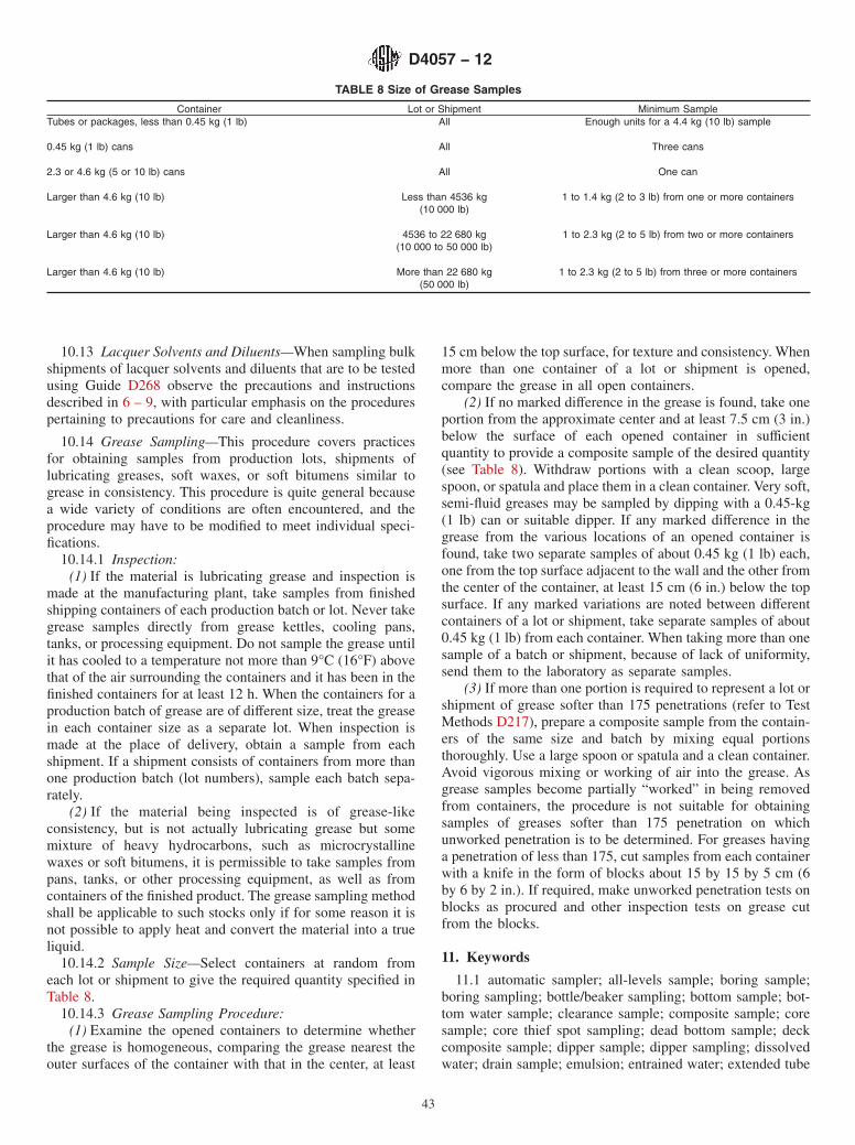
10.13 Lacquer Solvents and Diluents—When sampling bulkshipments of lacquer solvents and diluents that are to be testedusing Guide D268 observe the precautions and instructionsdescribed in 6 – 9, with particular emphasis on the procedurespertaining to precautions for care and cleanliness.
10.14 Grease Sampling—This procedure covers practicesfor obtaining samples from production lots, shipments oflubricating greases, soft waxes, or soft bitumens similar togrease in consistency. This procedure is quite general becausea wide variety of conditions are often encountered, and theprocedure may have to be modified to meet individual speci-fications.
10.14.1 Inspection:(1) If the material is lubricating grease and inspection is
made at the manufacturing plant, take samples from finishedshipping containers of each production batch or lot. Never takegrease samples directly from grease kettles, cooling pans,tanks, or processing equipment. Do not sample the grease untilit has cooled to a temperature not more than 9°C (16°F) abovethat of the air surrounding the containers and it has been in thefinished containers for at least 12 h. When the containers for aproduction batch of grease are of different size, treat the greasein each container size as a separate lot. When inspection ismade at the place of delivery, obtain a sample from eachshipment. If a shipment consists of containers from more thanone production batch (lot numbers), sample each batch sepa-rately.
(2) If the material being inspected is of grease-likeconsistency, but is not actually lubricating grease but somemixture of heavy hydrocarbons, such as microcrystallinewaxes or soft bitumens, it is permissible to take samples frompans, tanks, or other processing equipment, as well as fromcontainers of the finished product. The grease sampling methodshall be applicable to such stocks only if for some reason it isnot possible to apply heat and convert the material into a trueliquid.
10.14.2 Sample Size—Select containers at random fromeach lot or shipment to give the required quantity specified inTable 8.
10.14.3 Grease Sampling Procedure:(1) Examine the opened containers to determine whether
the grease is homogeneous, comparing the grease nearest theouter surfaces of the container with that in the center, at least
15 cm below the top surface, for texture and consistency. Whenmore than one container of a lot or shipment is opened,compare the grease in all open containers.
(2) If no marked difference in the grease is found, take oneportion from the approximate center and at least 7.5 cm (3 in.)below the surface of each opened container in sufficientquantity to provide a composite sample of the desired quantity(see Table 8). Withdraw portions with a clean scoop, largespoon, or spatula and place them in a clean container. Very soft,semi-fluid greases may be sampled by dipping with a 0.45-kg(1 lb) can or suitable dipper. If any marked difference in thegrease from the various locations of an opened container isfound, take two separate samples of about 0.45 kg (1 lb) each,one from the top surface adjacent to the wall and the other fromthe center of the container, at least 15 cm (6 in.) below the topsurface. If any marked variations are noted between differentcontainers of a lot or shipment, take separate samples of about0.45 kg (1 lb) from each container. When taking more than onesample of a batch or shipment, because of lack of uniformity,send them to the laboratory as separate samples.
(3) If more than one portion is required to represent a lot orshipment of grease softer than 175 penetrations (refer to TestMethods D217), prepare a composite sample from the contain-ers of the same size and batch by mixing equal portionsthoroughly. Use a large spoon or spatula and a clean container.Avoid vigorous mixing or working of air into the grease. Asgrease samples become partially “worked” in being removedfrom containers, the procedure is not suitable for obtainingsamples of greases softer than 175 penetration on whichunworked penetration is to be determined. For greases havinga penetration of less than 175, cut samples from each containerwith a knife in the form of blocks about 15 by 15 by 5 cm (6by 6 by 2 in.). If required, make unworked penetration tests onblocks as procured and other inspection tests on grease cutfrom the blocks.
11. Keywords
11.1 automatic sampler; all-levels sample; boring sample;boring sampling; bottle/beaker sampling; bottom sample; bot-tom water sample; clearance sample; composite sample; coresample; core thief spot sampling; dead bottom sample; deckcomposite sample; dipper sample; dipper sampling; dissolvedwater; drain sample; emulsion; entrained water; extended tube
TABLE 8 Size of Grease Samples
Container Lot or Shipment Minimum SampleTubes or packages, less than 0.45 kg (1 lb) All Enough units for a 4.4 kg (10 lb) sample
0.45 kg (1 lb) cans All Three cans
2.3 or 4.6 kg (5 or 10 lb) cans All One can
Larger than 4.6 kg (10 lb) Less than 4536 kg(10 000 lb)
1 to 1.4 kg (2 to 3 lb) from one or more containers
Larger than 4.6 kg (10 lb) 4536 to 22 680 kg(10 000 to 50 000 lb)
1 to 2.3 kg (2 to 5 lb) from two or more containers
Larger than 4.6 kg (10 lb) More than 22 680 kg(50 000 lb)
1 to 2.3 kg (2 to 5 lb) from three or more containers
D4057 − 12
43

sampling; floating piston cylinder; floating roof sample; freewater; grab sample; grab sampling; grease sample; greasesampling; high pressure sample cylinder; intermediate samplecontainer; loading zone sample; lower sample; marine custodytransfer; maximum fill density (reduced fill density); middlesample; multiple tank composite sample; outage tube (inter-nal); portable manual sampling unit; PSU; primary samplecontainer; representative sample; running sample; sample;
sample containers; sample handling; sample labeling; samplemixing; sample shipment; sampling; sampling cage; spotsample; standpipes; static sampling; suction sample (outlet);sump sample; surface (skim) sample; tank composite sample;tap sample; tap sampling; test specimen; top sample; tube orthief sample; tube sampling; upper sample; volumetric com-posite sample; zone sample
APPENDIX
(Nonmandatory Information)
X1. CRUDE OIL SAMPLE HANDLING—TEST MATRIX
X1.1 See Table X1.1.
D4057 − 12
44
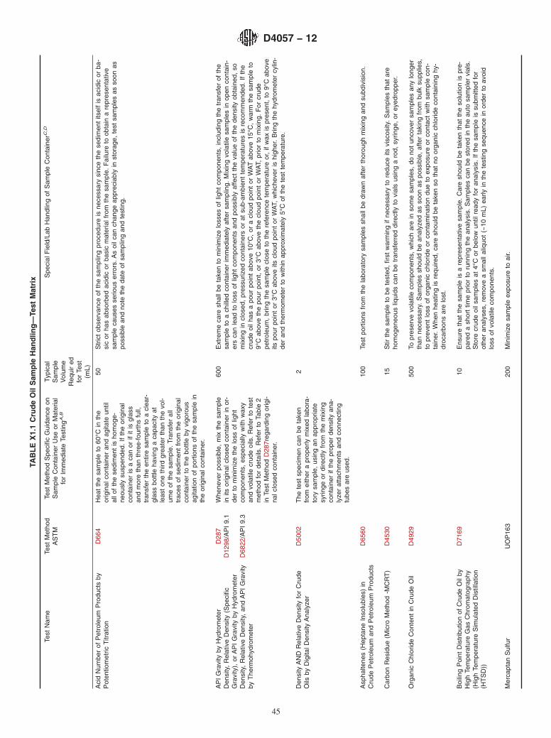
TAB
LE
X1.
1C
rud
eO
ilS
amp
leH
and
ling
—Te
stM
atri
x
Test
Nam
eTe
stM
etho
dA
ST
MTe
stM
etho
dS
peci
ficG
uida
nce
onS
ampl
eC
onta
iner
Use
orM
ater
ial
for
Imm
edia
teTe
stin
gA,B
Typi
cal
Sam
ple
Vol
ume
Req
uir
edfo
rTe
st(m
L)
Spe
cial
Fie
ld/L
abH
andl
ing
ofS
ampl
eC
onta
iner
C,D
Aci
dN
umbe
rof
Pet
role
umP
rodu
cts
byP
oten
tiom
etric
Titr
atio
nD
664
Hea
tth
esa
mpl
eto
60°C
inth
eor
igin
alco
ntai
ner
and
agita
teun
tilal
lof
the
sedi
men
tis
hom
oge-
neou
sly
susp
ende
d.If
the
orig
inal
cont
aine
ris
aca
nor
ifit
isgl
ass
and
mor
eth
anth
ree-
four
ths
full,
tran
sfer
the
entir
esa
mpl
eto
acl
ear-
glas
sbo
ttle
havi
nga
capa
city
atle
ast
one
third
grea
ter
than
the
vol-
ume
ofth
esa
mpl
e.Tr
ansf
eral
ltr
aces
ofse
dim
ent
from
the
orig
inal
cont
aine
rto
the
bottl
eby
vigo
rous
agita
tion
ofpo
rtio
nsof
the
sam
ple
inth
eor
igin
alco
ntai
ner.
50S
tric
tob
serv
ance
ofth
esa
mpl
ing
proc
edur
eis
nece
ssar
ysi
nce
the
sedi
men
tits
elf
isac
idic
orba
-si
cor
has
abso
rbed
acid
icor
basi
cm
ater
ialf
rom
the
sam
ple.
Fai
lure
toob
tain
are
pres
enta
tive
sam
ple
caus
esse
rious
erro
rs.A
soi
lcan
chan
geap
prec
iabl
yin
stor
age,
test
sam
ples
asso
onas
poss
ible
and
note
the
date
ofsa
mpl
ing
and
test
ing.
AP
IG
ravi
tyby
Hyd
rom
eter
D28
7W
hene
ver
poss
ible
,m
ixth
esa
mpl
ein
itsor
igin
alcl
osed
cont
aine
rin
or-
der
tom
inim
ize
the
loss
oflig
htco
mpo
nent
s,es
peci
ally
with
wax
yan
dvo
latil
ecr
ude
oils
.R
efer
tote
stm
etho
dfo
rde
tails
.R
efer
toTa
ble
2in
Test
Met
hod
D28
7reg
ardi
ngor
igi-
nalc
lose
dco
ntai
ner.
600
Ext
rem
eca
resh
allb
eta
ken
tom
inim
ize
loss
esof
light
com
pone
nts,
incl
udin
gth
etr
ansf
erof
the
sam
ple
toa
chill
edco
ntai
ner
imm
edia
tely
afte
rsa
mpl
ing.
Mix
ing
vola
tile
sam
ples
inop
enco
ntai
n-er
sca
nle
adto
loss
oflig
htco
mpo
nent
san
dpo
ssib
lyaf
fect
the
valu
eof
the
dens
ityob
tain
ed,
som
ixin
gin
clos
ed,
pres
suriz
edco
ntai
ners
orat
sub-
ambi
ent
tem
pera
ture
sis
reco
mm
ende
d.If
the
crud
eoi
lhas
apo
urpo
int
abov
e10
°C,
ora
clou
dpo
int
orW
AT
abov
e15
°C,
war
mth
esa
mpl
eto
9°C
abov
eth
epo
urpo
int,
or3°
Cab
ove
the
clou
dpo
int
orW
AT,
prio
rto
mix
ing.
For
crud
epe
trol
eum
,br
ing
the
sam
ple
clos
eto
the
refe
renc
ete
mpe
ratu
reor
,if
wax
ispr
esen
t,to
9°C
abov
eits
pour
poin
tor
3°C
abov
eits
clou
dpo
int
orW
AT,
whi
chev
eris
high
er.
Brin
gth
ehy
drom
eter
cylin
-de
ran
dth
erm
omet
erto
with
inap
prox
imat
ely
5°C
ofth
ete
stte
mpe
ratu
re.
Den
sity
,R
elat
ive
Den
sity
(Spe
cific
Gra
vity
),or
AP
IG
ravi
tyby
Hyd
rom
eter
D12
98/A
PI
9.1
Den
sity
,R
elat
ive
Den
sity
,an
dA
PI
Gra
vity
byT
herm
ohyd
rom
eter
D68
22/A
PI
9.3
Den
sity
AN
DR
elat
ive
Den
sity
for
Cru
deO
ilsby
Dig
italD
ensi
tyA
naly
zer
D50
02T
hete
stsp
ecim
enca
nbe
take
nfr
omei
ther
apr
oper
lym
ixed
labo
ra-
tory
sam
ple,
usin
gan
appr
opria
tesy
ringe
ordi
rect
lyfr
omth
em
ixin
gco
ntai
ner
ifth
epr
oper
dens
ityan
a-ly
zer
atta
chm
ents
and
conn
ectin
gtu
bes
are
used
.
2
Asp
halte
nes
(Hep
tane
Inso
lubl
es)
inC
rude
Pet
role
uman
dP
etro
leum
Pro
duct
sD
6560
100
Test
port
ions
from
the
labo
rato
rysa
mpl
essh
allb
edr
awn
afte
rth
orou
ghm
ixin
gan
dsu
bdiv
isio
n.
Car
bon
Res
idue
(Mic
roM
etho
d-M
CR
T)
D45
3015
Stir
the
sam
ple
tobe
test
ed,
first
war
min
gif
nece
ssar
yto
redu
ceits
visc
osity
.S
ampl
esth
atar
eho
mog
eneo
usliq
uids
can
betr
ansf
erre
ddi
rect
lyto
vial
sus
ing
aro
d,sy
ringe
,or
eyed
ropp
er.
Org
anic
Chl
orid
eC
onte
ntin
Cru
deO
ilD
4929
500
Topr
eser
vevo
latil
eco
mpo
nent
s,w
hich
are
inso
me
sam
ples
,do
not
unco
ver
sam
ples
any
long
erth
anne
cess
ary.
Sam
ples
shou
ldbe
anal
yzed
asso
onas
poss
ible
,af
ter
taki
ngfr
ombu
lksu
pplie
s,to
prev
ent
loss
ofor
gani
cch
lorid
eor
cont
amin
atio
ndu
eto
expo
sure
orco
ntac
tw
ithsa
mpl
eco
n-ta
iner
.W
hen
heat
ing
isre
quire
d,ca
resh
ould
beta
ken
soth
atno
orga
nic
chlo
ride
cont
aini
nghy
-dr
ocar
bons
are
lost
.
Boi
ling
Poi
ntD
istr
ibut
ion
ofC
rude
Oil
byH
igh
Tem
pera
ture
Gas
Chr
omat
ogra
phy
(Hig
hTe
mpe
ratu
reS
imul
ated
Dis
tilla
tion
(HT
SD
))
D71
6910
Ens
ure
that
the
sam
ple
isa
repr
esen
tativ
esa
mpl
e.C
are
shou
ldbe
take
nth
atth
eso
lutio
nis
pre-
pare
da
shor
ttim
epr
ior
toru
nnin
gth
ean
alys
is.
Sam
ples
can
best
ored
inth
eau
tosa
mpl
ervi
als.
Sto
recr
ude
oils
ampl
esat
4°C
orbe
low
until
read
yfo
ran
alys
is.
Ifth
esa
mpl
eis
subm
itted
for
othe
ran
alys
es,
rem
ove
asm
alla
liquo
t(~
10m
L)ea
rlyin
the
test
ing
sequ
ence
inor
der
toav
oid
loss
ofvo
latil
eco
mpo
nent
s.
Mer
capt
anS
ulfu
rU
OP
163
200
Min
imiz
esa
mpl
eex
posu
reto
air.
D4057 − 12
45

TAB
LE
X1.
1C
ontin
ued
Test
Nam
eTe
stM
etho
dA
ST
MTe
stM
etho
dS
peci
ficG
uida
nce
onS
ampl
eC
onta
iner
Use
orM
ater
ial
for
Imm
edia
teTe
stin
gA,B
Typi
cal
Sam
ple
Vol
ume
Req
uir
edfo
rTe
st(m
L)
Spe
cial
Fie
ld/L
abH
andl
ing
ofS
ampl
eC
onta
iner
C,D
Met
als
byA
A(N
i,V,
Fe,
Na)
D58
63,
Met
hod
B25
Prio
rto
wei
ghin
g,st
irth
esa
mpl
ean
dth
ensh
ake
the
sam
ple
inits
cont
aine
r.E
mpl
oyad
equa
tem
ixin
gan
dsa
mpl
ing
proc
edur
esfo
rcr
ude
and
heav
yoi
ls.
Use
pain
tm
ixer
sfo
rm
ixin
gof
crud
eoi
ls.
Ifth
esa
mpl
edo
esno
tre
adily
flow
atro
omte
mpe
ratu
re,
heat
the
sam
ple
toa
suffi
cien
tlyhi
ghan
dsa
fete
mpe
ratu
reto
ensu
read
equa
teflu
idity
.
Trac
eN
itrog
enin
Liqu
idP
etro
leum
Hy-
droc
arbo
nsby
Syr
inge
/Inle
tO
xida
tive
Com
bust
ion
and
Che
milu
min
esce
nce
De-
tect
ion
D46
293
Test
sam
ples
shou
ldbe
anal
yzed
asso
onas
poss
ible
afte
rta
king
from
bulk
supp
lies
topr
even
tlo
ssof
nitr
ogen
orco
ntam
inat
ion
due
toex
posu
reor
cont
act
with
the
sam
ple
cont
aine
r.If
the
test
sam
ple
isno
tus
edim
med
iate
ly,
then
thor
ough
lym
ixit
inits
cont
aine
rpr
ior
tota
king
ate
stsp
eci-
men
.S
ome
test
sam
ples
requ
irehe
atin
gin
orde
rto
thor
ough
lyho
mog
eniz
e.N
itrog
enby
Boa
t-In
let
Che
milu
min
es-
cenc
eD
5762
Pou
rP
oint
ofP
etro
leum
Pro
duct
sD
9750
The
pour
poin
tof
crud
eoi
lsis
very
sens
itive
totr
ace
amou
nts
ofhi
ghm
eltin
gw
axes
.E
xerc
ise
me-
ticul
ous
care
toen
sure
such
wax
es,
ifpr
esen
t,ar
eei
ther
com
plet
ely
mel
ted
or,
ifvo
latil
ityco
n-st
rain
tspr
even
the
atin
gto
com
plet
em
eltin
g,ho
mog
eneo
usly
susp
ende
din
the
sam
ple.
Insp
ect
the
wal
lsof
the
orig
inal
cont
aine
rto
ensu
reth
atno
high
mel
ting
poin
tm
ater
iali
sle
ftst
icki
ngto
the
wal
l.If
nece
ssar
y,re
heat
the
test
sam
ple
toa
tem
pera
ture
atle
ast
20°C
abov
eth
eex
pect
edpo
urpo
int
but
not
high
erth
ana
tem
pera
ture
of60
°C.
Itis
not
poss
ible
tode
fine
univ
ersa
lman
dato
ryru
les
for
the
prep
arat
ion
ofcr
ude
oilt
est
sam
ples
.
Pou
rP
oint
for
Cru
deO
ilsD
5853
,M
etho
dA
S&
Wby
Cen
trifu
ge—
Fie
ldP
roce
dure
AP
I10
.410
0R
efer
toA
PI
10.4
and
AP
I18
.1
S&
Wby
Cen
trifu
ge—
Labo
rato
ryP
roce
-du
reD
4007
/AP
I10
.310
0S
ampl
em
ixin
gis
typi
cally
requ
ired
toob
tain
ate
stpo
rtio
nre
pres
enta
tive
ofth
ebu
lksa
mpl
eto
bete
sted
,bu
tpr
ecau
tions
shal
lbe
take
nto
mai
ntai
nth
ein
tegr
ityof
the
sam
ple
durin
gth
isop
erat
ion.
Mix
ing
ofvo
latil
ecr
ude
petr
oleu
mco
ntai
ning
wat
eror
sedi
men
ts,
orbo
th,
may
resu
ltin
the
loss
oflig
htco
mpo
nent
s.A
dditi
onal
info
rmat
ion
onth
em
ixin
gan
dha
ndlin
gof
liqui
dsa
mpl
esca
nbe
foun
din
Pra
ctic
eD
5854
(AP
IM
PM
SC
hapt
er8.
3)
Sal
tsin
Cru
deO
il(E
lect
rom
etric
Met
hod)
D32
3010
The
pres
ence
ofw
ater
and
sedi
men
tw
illin
fluen
ceth
eco
nduc
tivity
ofth
esa
mpl
e.T
heut
mos
tca
resh
allb
eta
ken
inob
tain
ing
hom
ogen
ized
repr
esen
tativ
esa
mpl
es.
Sam
ples
ofve
ryvi
scou
sm
ater
i-al
sm
aybe
war
med
until
they
are
reas
onab
lyflu
idbe
fore
they
are
sam
pled
;ho
wev
er,
nosa
mpl
esh
allb
ehe
ated
mor
eth
anis
nece
ssar
yto
low
erth
evi
scos
ityto
am
anag
eabl
ele
vel.
Sal
tin
Cru
deO
il(P
oten
tiom
etric
Met
hod)
D64
7050
Hom
ogen
ize
the
sam
ple
with
in15
min
ofdr
awin
gth
ete
stsa
mpl
e.M
ixth
esa
mpl
eat
room
tem
-pe
ratu
re(1
5to
25°C
),or
less
,in
the
labo
rato
rysa
mpl
eco
ntai
ner,
and
reco
rdth
ete
mpe
ratu
reof
the
sam
ple
imm
edia
tely
befo
rem
ixin
g.H
eat
wax
ysa
mpl
es,
solid
atro
omte
mpe
ratu
re,
to3°
Cab
ove
thei
rpo
urpo
int
inor
der
tofa
cilit
ate
test
sam
ple
with
draw
al.
Sel
ect
the
type
ofm
ixer
rela
ted
toth
equ
antit
yof
crud
eoi
lin
the
labo
rato
rysa
mpl
eco
ntai
ner.
Sam
ple
mix
ers
are
tobe
verifi
edfo
rea
chty
peof
crud
eoi
l,si
zeof
sam
ple
and
shap
eof
cont
aine
r,an
dch
ange
insp
eed
ortim
eof
mix
ing,
follo
win
ggu
idel
ines
inA
nnex
A1
ofth
ete
stm
etho
d.F
orsm
alll
abor
ator
ysa
mpl
eco
ntai
ners
and
volu
mes
,50
to50
0m
L,a
non-
aera
ting,
high
spee
d(3
000
r/m
in),
shea
rm
ixer
isre
quire
d.U
seth
em
ixin
gtim
e,m
ixin
gsp
eed,
and
heig
htab
ove
the
botto
mof
the
cont
aine
rfo
und
tobe
satis
fac-
tory
toA
nnex
A1.
For
larg
erco
ntai
ners
and
volu
mes
,ap
prop
riate
mix
ing
cond
ition
ssh
allb
ede
-fin
edby
follo
win
ga
set
ofpr
oced
ures
sim
ilar
toth
ose
outli
ned
inA
nnex
A1,
and
Pra
ctic
eD
4177
(AP
IM
PM
SC
hapt
er8.
2)bu
tm
odifi
edfo
rap
plic
atio
nto
the
larg
erco
ntai
ners
and
volu
mes
.C
lean
and
dry
the
mix
erbe
twee
nsa
mpl
es.
Rec
ord
the
tem
pera
ture
ofth
esa
mpl
eim
med
iate
lyaf
ter
ho-
mog
eniz
atio
n.T
heris
ein
tem
pera
ture
from
the
initi
alre
adin
gsh
alln
otex
ceed
10°C
,ot
herw
ise
ex-
cess
ive
loss
ofvo
latil
eva
pors
can
occu
ror
the
disp
ersi
onca
nbe
com
eun
stab
le.
Inor
der
toen
sure
that
crud
eoi
lsw
ithra
pidl
yse
ttlin
gim
purit
ies
are
prop
erly
sam
pled
,w
ithdr
awth
ete
stsa
mpl
eco
n-ta
iner
imm
edia
tely
afte
rho
mog
eniz
atio
nby
low
erin
gth
etip
ofth
esa
mpl
etu
beal
mos
tto
the
bot-
tom
ofth
eco
ntai
ner,
and
with
draw
ing
the
test
sam
ple
asqu
ickl
yas
poss
ible
.C
lean
and
dry
the
sam
ple
tube
befo
rean
daf
ter
sam
plin
g.
D4057 − 12
46

TAB
LE
X1.
1C
ontin
ued
Test
Nam
eTe
stM
etho
dA
ST
MTe
stM
etho
dS
peci
ficG
uida
nce
onS
ampl
eC
onta
iner
Use
orM
ater
ial
for
Imm
edia
teTe
stin
gA,B
Typi
cal
Sam
ple
Vol
ume
Req
uir
edfo
rTe
st(m
L)
Spe
cial
Fie
ld/L
abH
andl
ing
ofS
ampl
eC
onta
iner
C,D
Sed
imen
tby
Ext
ract
ion
inC
rude
Oils
and
Fue
lOils
byth
eE
xtra
ctio
nM
etho
dD
473/
AP
I10
.120
Dra
wte
stpo
rtio
nsfr
omth
ela
bora
tory
sam
ples
imm
edia
tely
afte
rth
orou
ghm
ixin
g.H
eat
visc
ous
sam
ples
toa
tem
pera
ture
whi
chre
nder
sth
esa
mpl
eliq
uid,
and
hom
ogen
ize.
The
diffi
culti
esof
ob-
tain
ing
are
pres
enta
tive
test
port
ion
for
this
dete
rmin
atio
nar
eus
ually
grea
t,he
nce
the
need
for
grea
tat
tent
ion
toth
em
ixin
gan
dal
iquo
ting
step
s.A
ssp
ecifi
edin
Pra
ctic
eD
5854
(AP
IM
PM
SC
hapt
er8.
3)re
cord
the
tem
pera
ture
ofth
esa
mpl
ebe
fore
mix
ing.
Mix
the
labo
rato
rysa
mpl
ein
itsor
igin
alco
ntai
ner,
usin
gth
em
ixin
gtim
e,m
ixin
gpo
wer
(spe
ed),
and
posi
tion
rela
tive
toth
ebo
ttom
ofth
eco
ntai
ner
appr
opria
teto
the
crud
eoi
lbei
ngan
alyz
ed,
and
ases
tabl
ishe
dby
the
verifi
catio
nof
mix
ing
effic
ienc
y.To
avoi
dth
elo
ssof
light
ends
oper
ate
the
mix
erth
roug
ha
glan
din
the
clos
ure
ofth
esa
mpl
eco
ntai
ner.
Take
the
test
port
ion
for
anal
ysis
imm
edia
tely
afte
rm
ixin
g.R
ecor
dth
ete
mpe
ratu
reof
the
sam
ple
imm
edia
tely
afte
rm
ixin
g.If
the
rise
inte
mpe
ratu
redu
ring
mix
ing
ex-
ceed
s10
°C(2
0°F
),co
olth
esa
mpl
e,an
dre
peat
the
mix
ing
ata
low
eren
ergy
inpu
t.A
rise
inte
m-
pera
ture
grea
ter
than
10°C
(20°
F)
may
resu
ltin
ade
crea
sein
visc
osity
that
issu
ffici
ent
for
the
sedi
men
tto
settl
e.
Sed
imen
tin
Cru
deO
ilby
Mem
bran
eF
il-tr
atio
nD
4807
/AP
I10
.8A
naly
zesa
mpl
esw
ithin
two
wee
ksaf
ter
taki
ngth
esa
mpl
e.R
etai
ning
sam
ples
long
erm
ayaf
fect
the
re-
sults
.
20M
ixin
gis
requ
ired
topr
oper
lydi
sper
sese
dim
ent
asw
ella
san
yw
ater
pres
ent
inth
esa
mpl
e.M
ixth
esa
mpl
eat
room
tem
pera
ture
inth
eor
igin
alco
ntai
ner
with
in15
min
ofte
stin
gan
alys
isto
ensu
reco
mpl
ete
hom
ogen
eity
.Ate
stsa
mpl
edr
awn
dire
ctly
from
ala
rge
volu
me
dyna
mic
mix
ing
syst
emsh
allb
ean
alyz
edw
ithin
15m
inor
less
.Ana
lysi
ssh
ould
follo
wm
ixin
gas
soon
aspo
ssib
le.
The
15-m
inin
terv
alis
age
nera
lgui
delin
ew
hich
may
not
appl
yto
allc
rude
s,es
peci
ally
som
elig
htcr
udes
whi
chdo
not
hold
wat
eran
dse
dim
ent
insu
spen
sion
for
even
this
shor
ta
time.
Mix
ing
ofth
esa
mpl
esh
ould
not
incr
ease
the
tem
pera
ture
ofth
esa
mpl
em
ore
than
10°C
(20°
F)
ora
loss
ofw
ater
may
occu
raf
fect
ing
the
sam
ple’
sco
mpo
sitio
n.T
hety
peof
mix
erde
pend
son
the
quan
tity
ofcr
ude.
Bef
ore
any
unkn
own
mix
eris
used
,th
esp
ecifi
catio
nsfo
rth
eho
mog
eniz
atio
nte
st,
Pra
ctic
eD
5854
(AP
IM
PM
SC
hapt
er8.
3),
mus
tbe
met
.T
hem
ixer
mus
tbe
re-e
valu
ated
follo
win
gan
ych
ange
sin
the
type
ofcr
ude,
quan
tity
ofcr
ude,
orsh
ape
ofth
esa
mpl
eco
ntai
ner.
For
smal
ltes
tsa
mpl
evo
lum
es,
50to
300
mL,
ano
n-ae
ratin
g,hi
gh-s
peed
,sh
ear
mix
eris
requ
ired.
Use
the
mix
-in
gtim
e,m
ixin
gsp
eed,
and
heig
htab
ove
the
botto
mof
the
cont
aine
rfo
und
tobe
satis
fact
ory
inP
ract
ice
D58
54(A
PI
MP
MS
Cha
pter
8.3)
.C
lean
and
dry
the
mix
erbe
twee
nsa
mpl
es.
Sul
fur
inP
etro
leum
Pro
duct
sby
Wav
e-le
ngth
Dis
pers
ive
Xra
yF
luor
esce
nce
Spe
ctro
met
ry
D26
2225
mL
Sul
fur
Con
tent
D42
9450
0m
L
Vap
orP
ress
ure
ofP
etro
leum
Pro
duct
s(R
eid
Met
hod)
D32
3S
ampl
eC
onta
iner
Siz
e—T
hesi
zeof
the
sam
ple
cont
aine
rfr
omw
hich
the
vapo
rpr
essu
resa
mpl
eis
take
nsh
allb
e1
L(1
qt).
Itsh
allb
e70
to80
%fil
led
with
sam
ple.
Inno
case
shal
lany
part
ofth
eR
eid
(D32
3-sp
ecifi
c)ap
para
tus
itsel
fbe
used
asth
esa
mpl
eco
ntai
ner
prio
rto
actu
-al
lyco
nduc
ting
the
test
.
1000
Test
tobe
perf
orm
edon
sam
ples
from
prim
ary
sam
ple
cont
aine
r,an
dno
ta
com
posi
te.
The
ex-
trem
ese
nsiti
vity
ofva
por
pres
sure
mea
sure
men
tsto
loss
esth
roug
hev
apor
atio
nan
dth
ere
sulti
ngch
ange
sin
com
posi
tion
issu
chas
tore
quire
the
utm
ost
prec
autio
nan
dth
em
ost
met
icul
ous
care
inth
eha
ndlin
gof
sam
ples
.T
heR
eid
vapo
rpr
essu
rede
term
inat
ion
shal
lbe
perf
orm
edon
the
first
test
spec
imen
with
draw
nfr
omth
esa
mpl
eco
ntai
ner.
The
rem
aini
ngsa
mpl
ein
the
cont
aine
rca
nnot
beus
edfo
ra
seco
ndva
por
pres
sure
dete
rmin
atio
n.P
rote
ctsa
mpl
esfr
omex
cess
ive
tem
pera
ture
spr
ior
tote
stin
g.D
ono
tte
stsa
mpl
esin
leak
yco
ntai
ners
.T
hey
shou
ldbe
disc
arde
dan
dne
wsa
mpl
esob
tain
ed.
Coo
lthe
sam
ple
cont
aine
ran
dco
nten
tsto
0to
1°C
(32
to34
°F)
befo
reth
eco
n-ta
iner
isop
ened
.S
uffic
ient
time
tore
ach
this
tem
pera
ture
shal
lbe
ensu
red
bydi
rect
mea
sure
men
tof
the
tem
pera
ture
ofa
sim
ilar
liqui
din
alik
eco
ntai
ner
plac
edin
the
cool
ing
bath
atth
esa
me
time
asth
esa
mpl
e.R
efer
toP
ract
ice
D58
54(A
PI
MP
MS
Cha
pter
8.3)
.
Tota
lVap
orP
ress
ure
(Min
iMet
hod)
D51
91
Det
erm
inat
ion
ofV
apor
Pre
ssur
eof
Cru
deO
il:V
PC
R(E
xpan
sion
Met
hod)
D63
77If
crud
ew
asno
n-pr
essu
rized
and
sam
pled
follo
win
gA
ST
MD
4057
orD
4177
500
D4057 − 12
47

TAB
LE
X1.
1C
ontin
ued
Test
Nam
eTe
stM
etho
dA
ST
MTe
stM
etho
dS
peci
ficG
uida
nce
onS
ampl
eC
onta
iner
Use
orM
ater
ial
for
Imm
edia
teTe
stin
gA,B
Typi
cal
Sam
ple
Vol
ume
Req
uir
edfo
rTe
st(m
L)
Spe
cial
Fie
ld/L
abH
andl
ing
ofS
ampl
eC
onta
iner
C,D
Det
erm
inat
ion
ofV
apor
Pre
ssur
eof
Cru
deO
il:D
6377
Ifcr
ude
was
pres
suriz
edan
dsa
mpl
edfo
llow
ing
D37
00or
D41
7750
0S
ampl
ing
ofliv
ecr
ude
oils
hall
bepe
rfor
med
inac
cord
ance
with
Pra
ctic
eD
3700
,an
dsp
ecifi
cgu
id-
ance
inA
ST
MD
6377
.If
the
sam
ple
isco
ntai
ned
ina
pres
suriz
edso
urce
like
api
pelin
e,us
ea
float
ing
pist
oncy
linde
ran
dob
tain
the
sam
ple
dire
ctly
from
the
sour
ceun
der
pres
sure
.R
inse
the
cylin
der
byop
enin
gth
erin
sing
valv
eun
tilth
ecr
ude
oile
mer
ges
atth
ese
cond
inle
t.C
lose
the
rins-
ing
valv
ean
dle
tth
epi
ston
mov
esl
owly
until
atle
ast
200
mL
ofsa
mpl
eha
sen
tere
dth
ecy
linde
r.C
lose
the
inle
tva
lve
and
appl
yth
eba
ckpr
essu
reim
med
iate
ly.
Che
ckth
efil
ling
ofth
ecy
linde
rto
beat
leas
t20
0m
L.T
hecu
rren
tpr
ecis
ion
stat
emen
tsw
ere
deriv
edfr
omth
e20
05IL
Sus
ing
sam
ples
in25
0m
Lflo
atin
gpi
ston
cylin
ders
.D
ono
tun
nece
ssar
ilyex
pose
the
sam
ples
tote
mpe
ra-
ture
sex
ceed
ing
30°C
durin
gsa
mpl
ing
and
stor
age.
For
prol
onge
dst
orag
e,st
ore
the
sam
ples
inan
appr
opria
tero
omor
refr
iger
ator
.P
erfo
rmth
eva
por
pres
sure
dete
rmin
atio
non
the
first
test
spec
i-m
enw
ithdr
awn
from
the
cylin
der
afte
rth
erin
sing
step
inth
ete
stm
etho
d.D
ono
tus
eth
ere
mai
n-in
gsa
mpl
ein
the
float
ing
pist
oncy
linde
rfo
rm
ore
than
thre
ere
peat
vapo
rpr
essu
rede
term
inat
ions
.Tr
ansf
erth
esa
mpl
efr
omth
ecy
linde
rco
ntai
ner
into
the
mea
surin
gce
llat
room
tem
pera
ture
but
atle
ast
5°C
abov
eth
epo
urpo
int.
Ifth
esa
mpl
eis
cont
aine
din
apr
essu
rized
float
ing
pist
oncy
linde
r,ap
ply
aba
ck-p
ress
ure
whi
chis
high
erth
anth
eva
por
pres
sure
ofth
esa
mpl
eat
the
intr
oduc
tion
tem
pera
ture
plus
am
inim
umof
100
kPa
for
the
pist
onm
ovem
ent.
The
appl
ied
back
-pre
ssur
esh
all
not
exce
edth
em
axim
umlim
itof
the
pres
sure
tran
sduc
erus
edin
the
vapo
rpr
essu
reap
para
tus.
Vis
cosi
ty-
Kin
emat
icD
445
100
Hea
tin
the
orig
inal
cont
aine
r,in
anov
en,
at60
±2°
Cfo
r1
h.T
horo
ughl
yst
irth
esa
mpl
ew
itha
suita
ble
rod
ofsu
ffici
ent
leng
thto
reac
hth
ebo
ttom
ofth
eco
ntai
ner.
Con
tinue
stirr
ing
until
ther
eis
nosl
udge
orw
axad
herin
gto
the
rod.
Rec
apth
eco
ntai
ner
tight
lyan
dsh
ake
vigo
rous
lyfo
r1
min
toco
mpl
ete
the
mix
ing.
With
sam
ples
ofa
very
wax
yna
ture
oroi
lsof
high
kine
mat
icvi
scos
ity,
itm
aybe
nece
ssar
yto
incr
ease
the
heat
ing
tem
pera
ture
abov
e60
°Cto
achi
eve
prop
erm
ixin
g.T
hesa
mpl
esh
ould
besu
ffici
ently
fluid
for
ease
ofst
irrin
gan
dsh
akin
g.Im
med
iate
lyaf
ter
mix
ing,
pour
suffi
cien
tsa
mpl
eto
fillt
wo
visc
omet
ers
into
a10
0-m
Lgl
ass
flask
and
loos
ely
stop
per.
Wat
erin
Cru
deO
ilby
Dis
tilla
tion
D40
06/A
PI
10.2
200
Wat
erin
Cru
deO
ilsby
Pot
entio
met
ricK
arlF
isch
erTi
trat
ion
D43
77/A
PI
10.7
50M
ixth
ete
stsa
mpl
eof
crud
eoi
lwith
in15
min
befo
rean
alys
isto
insu
reco
mpl
ete
hom
ogen
eity
.M
ixth
ete
stsa
mpl
eat
room
tem
pera
ture
(25°
C)
inth
eor
igin
alco
ntai
ner.
Mix
ing
ofth
esa
mpl
esh
ould
not
incr
ease
the
tem
pera
ture
ofth
esa
mpl
em
ore
than
10°C
,or
alo
ssof
wat
erm
ayoc
cur.
The
type
ofm
ixer
depe
nds
onth
equ
antit
yof
crud
e.B
efor
ean
yun
know
nm
ixer
isus
ed,
the
spec
ifica
-tio
nsfo
rth
eho
mog
eniz
atio
nte
st,A
nnex
A1
ofth
eTe
stM
etho
d(o
rP
ract
ice
D58
54(A
PI
MP
MS
Cha
pter
8.3)
for
Test
Met
hod
D49
29),
mus
tbe
met
.T
hem
ixer
mus
tbe
re-e
valu
ated
for
any
chan
ges
inth
ety
peof
crud
e,qu
antit
yof
crud
e,or
shap
eof
the
sam
ple
cont
aine
r.F
orsm
all
sam
ple
volu
mes
,50
to50
0m
L,a
non-
aera
ting,
high
spee
d,sh
ear
mix
eris
requ
ired.
Use
the
mix
-in
gtim
e,m
ixin
gsp
eed,
and
heig
htab
ove
the
botto
mof
the
cont
aine
rfo
und
tobe
satis
fact
ory
inA
nnex
A1
ofth
eTe
stM
etho
d(o
rP
ract
ice
D58
54(A
PI
MP
MS
Cha
pter
8.3)
).C
lean
and
dry
the
mix
erbe
twee
nsa
mpl
es.
Wat
erC
onte
ntby
Kar
lFis
her
(Cou
lom
et-
ric)
D49
28/A
PI
10.9
AIn
addi
tion
toth
esp
ecifi
cte
stm
etho
d,fo
rsa
mpl
eco
ntai
ner
guid
ance
for
imm
edia
tete
stin
g,sa
mpl
est
orag
e,an
dsa
mpl
eco
ntai
ner
reus
e,re
fer
toP
ract
ice
D58
54(A
PI
MP
MS
Cha
pter
8.3)
.B
At
min
imum
,al
lsam
ple
cont
aine
rsar
eto
becl
ean
and
dry.
CA
llsa
mpl
eco
ntai
ners
shou
ldal
low
15to
30%
ulla
gefo
rpo
ssib
leex
pans
ion.
Inad
ditio
n,w
ithth
eex
cept
ion
ofva
por
pres
sure
test
met
hods
,sam
ples
are
tobe
hom
ogen
ized
ever
ytim
eth
esa
mpl
eis
bein
gtr
ansf
erre
dan
dim
med
iate
lypr
ior
tote
stin
g.D
The
mos
tcu
rren
tte
stm
etho
din
stru
ctio
nsw
illta
kepr
eced
ence
over
anyt
hing
cont
aine
dw
ithin
this
mat
rix.
D4057 − 12
48

ASTM International takes no position respecting the validity of any patent rights asserted in connection with any item mentionedin this standard. Users of this standard are expressly advised that determination of the validity of any such patent rights, and the riskof infringement of such rights, are entirely their own responsibility.
This standard is subject to revision at any time by the responsible technical committee and must be reviewed every five years andif not revised, either reapproved or withdrawn. Your comments are invited either for revision of this standard or for additional standardsand should be addressed to ASTM International Headquarters. Your comments will receive careful consideration at a meeting of theresponsible technical committee, which you may attend. If you feel that your comments have not received a fair hearing you shouldmake your views known to the ASTM Committee on Standards, at the address shown below.
This standard is copyrighted by ASTM International, 100 Barr Harbor Drive, PO Box C700, West Conshohocken, PA 19428-2959,United States. Individual reprints (single or multiple copies) of this standard may be obtained by contacting ASTM at the aboveaddress or at 610-832-9585 (phone), 610-832-9555 (fax), or [email protected] (e-mail); or through the ASTM website(www.astm.org). Permission rights to photocopy the standard may also be secured from the Copyright Clearance Center, 222Rosewood Drive, Danvers, MA 01923, Tel: (978) 646-2600; http://www.copyright.com/
D4057 − 12
49
![Reduction of Oil Content in Degreasing Tank of Phosphating ......[4] ASTM, D4007–81: Standard test method for water and sediment in crude oil by the centrifuge method, in: Annua](https://img.pdfslide.us/doc/110x75/6109e28f891783523b688235/reduction-of-oil-content-in-degreasing-tank-of-phosphating-4-astm-d4007a81.jpg)