Embed Size (px)
Citation preview

Standard Operating Procedure (SOP)
For
Water Sampling at Pelaez Ranch using ISCO 3700
Compiled by:
Prosper Zigah
November, 2004
Reviewed by:
Mario Lindner
August, 2005
Copyright © 2004 Southern DataStream, Inc.

CONTENTS
1. Introduction ...................................................................................................... 6
1.1 General Trip Preparations............................................................................. 6
2. General Information............................................................................................. 7
2.1 QA/QC Measures ........................................................................................... 7
2.2 ISCO Sampling ............................................................................................... 7
3. ISCO Installation and Programming.................................................................... 9
3.1 Installation...................................................................................................... 9
3.1.1 3700 Sampler Setup Procedures.................................................................. 9
3.1.1.1 Preparing the Base Section ................................................................ 9
3.1.1.2 Attaching the Suction Line................................................................. 10
3.1.1.2 Placement of the Suction Line and Intake ....................................... 10
3.1.1.3 Intake Placement.............................................................................. 10
3.1.1.4 Connection to Power Source ........................................................... 10
3.1.1.5 Placing the Sampler ......................................................................... 10
3.1.1.6 Connection to a CR 205................................................................... 11
3.2 ISCO Configuration ..................................................................................... 11
3.3 ISCO Programming...................................................................................... 12
4. Preparing a Tray with Bottles for the Field ....................................................... 14
4.1 ISCO Sample Bottle Cleaning ...................................................................... 14
4.2 Bottle Labeling ............................................................................................. 14
4.3 Cleaning the Caps ........................................................................................ 15
5. Sample Collection and Bottle Tray Change....................................................... 15
6. Sample Processing ............................................................................................. 20
6.1 Filter Equipments & Cleaning ..................................................................... 20
6.2 Filtering........................................................................................................ 20
6.3 Preservation ................................................................................................. 20
6.4 Storage.......................................................................................................... 20
3

7. Documentation ................................................................................................... 21
7.1 Field Note Book............................................................................................ 21
7.2 Chain of Custody .......................................................................................... 21
7.3 Pelaez Project Binders ................................................................................. 23
7.4 Digital Document Records ........................................................................... 23
7.5 Making Photocopy........................................................................................ 23
8. Quarterly Maintenance....................................................................................... 23
8.1 ISCO Automatic Sampler Distributor Arm .................................................. 23
8.2 ISCO Sampler Metal Tube ........................................................................... 24
8.3 Sampler Suction Intake................................................................................. 24
8.4 Sample Tubing Decontamination ................................................................. 24
9. Supplies for Operation and Maintenance........................................................... 24
4
LIST OF TABLES
Table 1: Datalogger control program....................................................................... 8
Table 2: ISCO configuration procedure................................................................ 11
Table 3: ISCO programming procedure. ............................................................... 13
Table 4: Retrieving sampling event data from ISCO. .......................................... 16
Table 5: Example of COC form for station 3. ....................................................... 22
LIST OF FIGURES Figure 1: Location of flume stations and Wells...................................................... 6
Figure 2: ISCO 3700 auto sampler installed at the flume station............................ 9
Figure 3: Displayed information before sampler can take samples...................... 13
Figure 4: Example of labeled bottle...................................................................... 15
Figure 5: Opening latches at sides of ISCO sampler. ........................................... 17
Figure 6: Removing middle portion of ISCO to expose bottles. .......................... 17
Figure 7: Bottom portion of ISCO showing sample containers............................ 18
Figure 8: Lifting tray of bottles filled with samples. ............................................ 19
5

1. Introduction This SOP is prepared as a working document for SDS for collection of water quality samples from Pelaez Ranch.
1.1 General Trip Preparations
Refer to the binder: SOP for Kirton Ranch at the office for guidelines for preparations for field trip or the website http://portlabelle.us/mahmud/web/
Figure 1: Location of flume stations and Wells.
6

2. General Information
2.1 QA/QC Measures
2.1.1 In addition to standard samples, the field technicians collect equipment blanks (EB) and field duplicate samples (FD). The EBs are 2 bottles (one capped [bottle 25] and the other uncapped [bottle 26]) field with deionized water and placed at the center of the sampling tray. The field duplicates are bottles 2, 12 and 22.
2.1.2 Overall care must be taken in regards to equipment handling, container handling/storage, decontamination, and record keeping. Sample collection equipment and non preserved sample containers must be rinsed three times with sample water before the actual sample is taken. An exception to this is any pre-preserved container.
2.1.3 If protective gloves are used, they shall be clean, new and disposable. These should be changed upon arrival at a new sampling point.
2.1.4 If possible, one member of the field team should take all the notes, fill out labels, etc., while the other member does all of the sampling.
2.2 ISCO Sampling
2.2.1 Flow proportional sampling from streams and canals produces the most representative water quality samples by virtue of the sample number and/or size being proportional to flow volume or flow rate. The advantage of flow proportional sampling is more pronounced in the case of variable flow canals or streams. In sites where the sampling equipment is serviced once a week or less frequently, the design of a sampling scheme to determine sampling volumes for variable flow canals is essential. Surface water samples are collected from each ditch using an ISCO portable automatic water sampler interfaced with a programmable datalogger /controller (CR205).
2.2.2 For each pre-determined sampling volume of flow, the CR205 controller triggers the auto sampler to collect a sample (aliquot) by sending a 12V pulse of a one second duration from C port to the pin C of the ISCO flow meter. Optimum sampling volume trigger points are desired to collect representative water quality samples throughout the week with minimum chance of filling all the bottles or leaving a lot of sampling bottles empty before the next service.
2.2.3 Flow proportional automatic sampling procedures are only applicable to long holding time (28 days) parameters: TKN, TP, NOx and NH4.
7
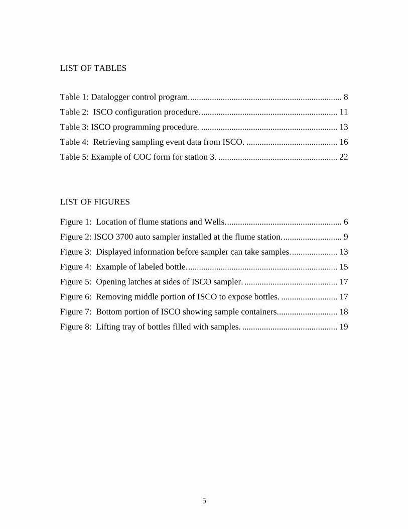
2.2.4 The ISCO 3700 auto samplers are supplied with 500 mL bottles
2.2.5 The 450 mL samples are collected at predetermined volumes of flow, as measured by an associated CR205 data logger.
2.2.6 Each bottle receives one sample according to the flow volumes shown in Table 1.
Table 1: Datalogger control program.
Accum. Depth inches
Trigger Value feet
Bottle Number
QA/QC
Code 0.02 0.00167 1 0.02 0 2 FD 0.04 0.00167 3 0.06 0.00167 4 0.10 0.00334 5 0.14 0.00334 6 0.18 0.00334 7 0.26 0.00668 8 0.34 0.00668 9 0.42 0.00668 10 0.58 0.01336 11 0.58 0 12 FD 0.74 0.01336 13 1.06 0.02672 14 1.38 0.02672 15 1.70 0.02672 16 2.34 0.05344 17 2.99 0.05344 18 3.63 0.05344 19 4.91 0.10688 20 6.19 0.10688 21 6.19 0 22 FD 8.76 0.21376 23 11.32 0.21376 24
8
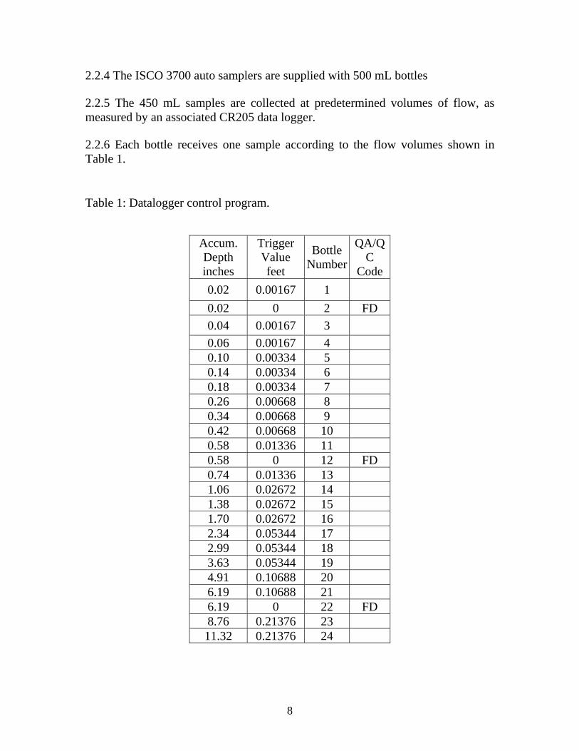
3. ISCO Installation and Programming
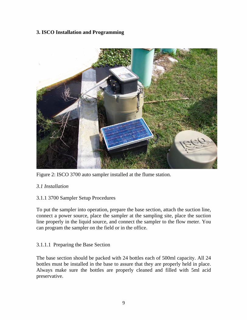
Figure 2: ISCO 3700 auto sampler installed at the flume station.
3.1 Installation
3.1.1 3700 Sampler Setup Procedures
To put the sampler into operation, prepare the base section, attach the suction line, connect a power source, place the sampler at the sampling site, place the suction line properly in the liquid source, and connect the sampler to the flow meter. You can program the sampler on the field or in the office.
3.1.1.1 Preparing the Base Section The base section should be packed with 24 bottles each of 500ml capacity. All 24 bottles must be installed in the base to assure that they are properly held in place. Always make sure the bottles are properly cleaned and filled with 5ml acid preservative.
9

3.1.1.2 Attaching the Suction Line The suction line is the piece of tubing that extends from the sampler’s pump tubing intake, at the top of the liquid detector, to the liquid source. We are using 3/8-inch (0.94) ID vinyl tubing. The length of the suction line should be in whole-foot increments: lengths of 4 feet, not 3.5 feet. The controller will accept only whole numbers as suction-line lengths. To ensure the accuracy of the sampler, you must enter a suction-line length equal that of the actual line measurement. When programming the sampler, you must enter the inside diameter, type, and length of suction line used. Cut the line to the shortest length feasible: this aids the downhill routing. Avoid loops of coiled suction line, which may hold residual amounts of liquid that would cross-contaminate sample volumes. A shorter suction line will also extend battery life and pump tube life because the sampler will require a shorter pumping cycle to deliver the sample volume.
3.1.1.2 Placement of the Suction Line and Intake Route the line from sampler to sampling point so that it is continuously sloped downhill. This helps to drain the suction line when the peristaltic pump reverses to purge the line, and minimizes the possibility of cross contamination
3.1.1.3 Intake Placement The proper placement of the sampler intake assures the collection of representative samples. Place the intake in the main flow, not in an eddy or at the edge of flow. The vertical position of the intake in the flow is important. An intake at the bottom may result in excess heavy solids and no floating materials, while placement at the top may result in the opposite.
3.1.1.4 Connection to Power Source The 3700 sampler should be properly connected to 12 VDC power sources. At Pelaez Ranch the power sources (battery and solar panel) are already set. Just make sure you connect the power cable to the sampler.
3.1.1.5 Placing the Sampler Place the ISCO sampler on a relatively flat surface. Placing it on a steep incline may cause the sample to miss the bottle opening. When installing the sampler, be sure the head - the vertical distance between the level of the liquid source and the pump - is no greater than 26 feet. The pump will not be able to deliver samples for heads of 26 feet or greater.
10

3.1.1.6 Connection to a CR 205 The cable for the flow meter should be properly attached to the CR 205 connector on the side of the sampler.
3.2 ISCO Configuration
• Start off by opening the case of the ISCO sampler. Just un-do the three locks at the sides and lift the case.
• Press ON/OFF key on the control panel to switch the sampler on. • Press ENTER/ PROGRAM key • Select CONFIGURE using arrow keys and press ENTER • Then follow the directions in the table to configure the sampler
Table 2: ISCO configuration procedure.
Option Settings press set clock time Enter multiple timesbottles and sizes portable, 24 bottles enter bottle volume 500 enter suction line 3/8 inch enter vinyl enter
Suction line length is 14 feet enter
liquid detector enable enter rinse cycle 3 enter enter head manually no enter retry up to 1 times yes enter programming mode basic enter calibrate sample disable enter start time delay 0 enter enable pin no enter sample upon disable no enter sample upon enable no enter reset, sample interval no enter inhibit countdown no enter event mark Just enter enter Use arrors select Pulse enter FWD pumping enter
11

purge counts yes enter pre sample 150 enter post sample 922 enter tubing life enter enter reset pump counter no enter pump count to warning 500,000 enter program lock disable enter sampler ID ID number enter run diagnostic run enter Wait for sampler to run. It will make a noise after it is done. Test distributor yes enter Wait for few seconds. The distributor will be turning and making slight noise. Continue to wait until re-initialize is displayed. Reinitialize no enter exit configuration exit enter
After you have configured the sampler, continue immediately to program it.
3.3 ISCO Programming
• Press ENTER/ PROGRAM key • Select PROGRAM and press ENTER • Then follow the directions in the table to program the sampler
12
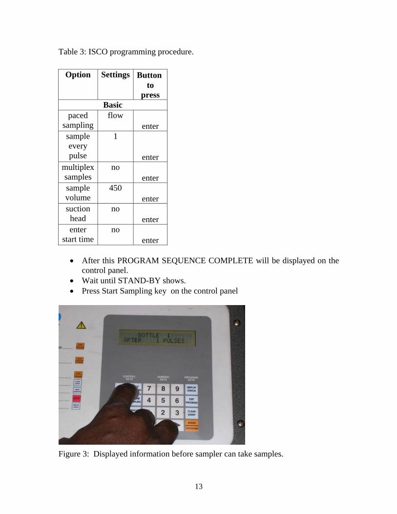
Table 3: ISCO programming procedure.
Button Option Settings to
press Basic
paced sampling
flow enter
sample every pulse
1
enter multiplex samples
no enter
sample volume
450 enter
suction head
no enter
enter start time
no enter
• After this PROGRAM SEQUENCE COMPLETE will be displayed on the
control panel. • Wait until STAND-BY shows. • Press Start Sampling key on the control panel
Figure 3: Displayed information before sampler can take samples.
13

• Finally press ENTER when “Bottle one after one pulse” is shown on the
display screen.
4. Preparing a Tray with Bottles for the Field These steps should be followed in preparing sampler bottles for use on the field
4.1 ISCO Sample Bottle Cleaning
The auto sampler bottles used in the ISCOs must first be cleaned in the field laboratory or at the office lab using the standard EPA bottle cleaning procedure. This procedure also applies to cleaning of other sampling equipment (buckets, dippers, etc.).
• Clean with tap water and lab grade soap (Micro 90) using a brush, if necessary, to remove particulate matter or surface film.
• Rinse thoroughly with tap water. • Rinse thoroughly with DI water. Enough water shall be used to ensure that
all equipment surfaces are flushed with water. • Rinse thoroughly with analyte-free water and allow to air dry as long as
possible. • Cap and store • Clean sampling bottles / equipments shall be wrapped in plastic bags to
prevent contamination during storage or transport to the field. • If no further sampling is to be performed, equipment must be put in plastic
bags.
4.2 Bottle Labeling
Sample bottles are labeled after the retrieving the bottles with samples from the field
Containers for collecting water samples on field ( write flume no., bottle no., date e.g. F1B12 11/10/2004)
14
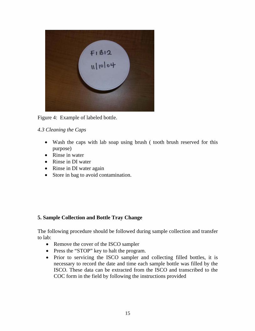
Figure 4: Example of labeled bottle.
4.3 Cleaning the Caps
• Wash the caps with lab soap using brush ( tooth brush reserved for this purpose)
• Rinse in water • Rinse in DI water • Rinse in DI water again • Store in bag to avoid contamination.
5. Sample Collection and Bottle Tray Change The following procedure should be followed during sample collection and transfer to lab:
• Remove the cover of the ISCO sampler • Press the “STOP” key to halt the program. • Prior to servicing the ISCO sampler and collecting filled bottles, it is
necessary to record the date and time each sample bottle was filled by the ISCO. These data can be extracted from the ISCO and transcribed to the COC form in the field by following the instructions provided
15
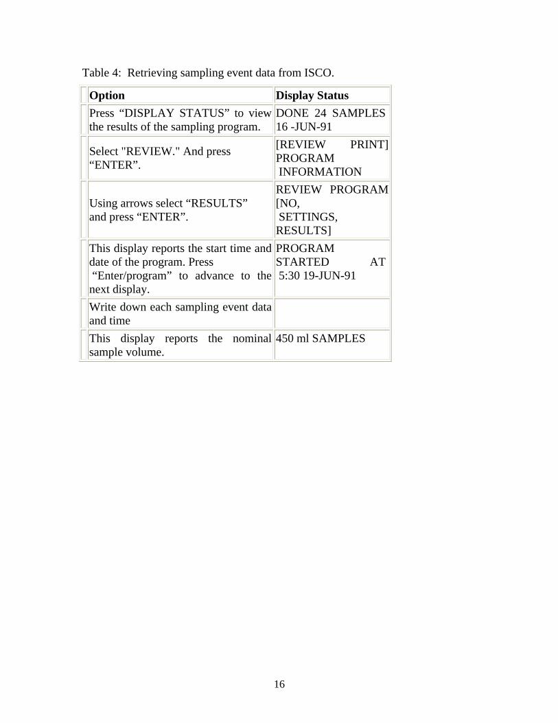
Table 4: Retrieving sampling event data from ISCO.
Option Display Status Press “DISPLAY STATUS” to view
the results of the sampling program. DONE 24 SAMPLES 16 -JUN-91
Select "REVIEW." And press “ENTER”.
[REVIEW PRINT] PROGRAM INFORMATION
Using arrows select “RESULTS” and press “ENTER”.
REVIEW PROGRAM [NO, SETTINGS, RESULTS]
This display reports the start time and date of the program. Press “Enter/program” to advance to the next display.
PROGRAM STARTED AT 5:30 19-JUN-91
Write down each sampling event data and time
This display reports the nominal sample volume.
450 ml SAMPLES
16

Figure 5: Opening latches at sides of ISCO sampler.
Figure 6: Removing middle portion of ISCO to expose bottles.
17
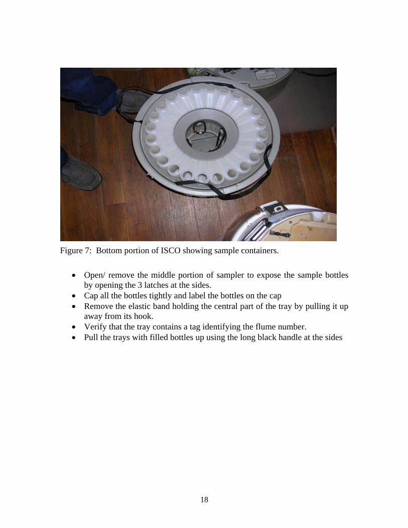
Figure 7: Bottom portion of ISCO showing sample containers.
• Open/ remove the middle portion of sampler to expose the sample bottles by opening the 3 latches at the sides.
• Cap all the bottles tightly and label the bottles on the cap • Remove the elastic band holding the central part of the tray by pulling it up
away from its hook. • Verify that the tray contains a tag identifying the flume number. • Pull the trays with filled bottles up using the long black handle at the sides
18
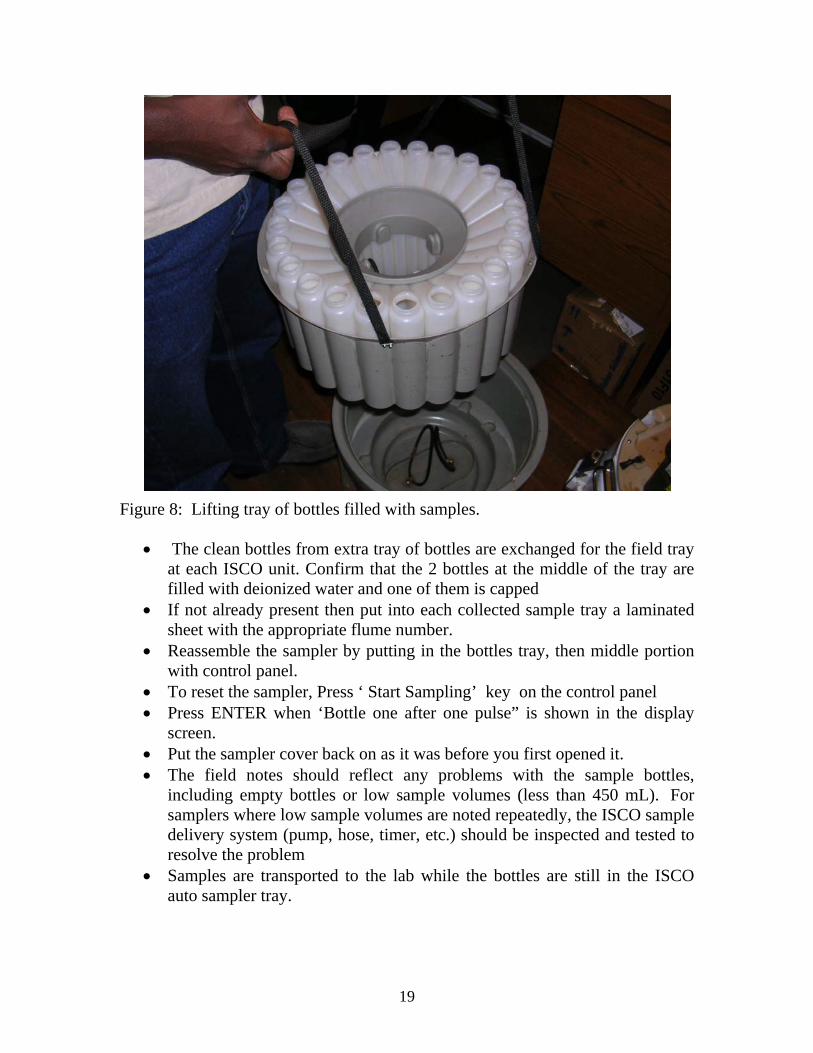
Figure 8: Lifting tray of bottles filled with samples.
• The clean bottles from extra tray of bottles are exchanged for the field tray at each ISCO unit. Confirm that the 2 bottles at the middle of the tray are filled with deionized water and one of them is capped
• If not already present then put into each collected sample tray a laminated sheet with the appropriate flume number.
• Reassemble the sampler by putting in the bottles tray, then middle portion with control panel.
• To reset the sampler, Press ‘ Start Sampling’ key on the control panel • Press ENTER when ‘Bottle one after one pulse” is shown in the display
screen. • Put the sampler cover back on as it was before you first opened it. • The field notes should reflect any problems with the sample bottles,
including empty bottles or low sample volumes (less than 450 mL). For samplers where low sample volumes are noted repeatedly, the ISCO sample delivery system (pump, hose, timer, etc.) should be inspected and tested to resolve the problem
• Samples are transported to the lab while the bottles are still in the ISCO auto sampler tray.
19
6. Sample Processing In the lab the caps of all sampler bottles are labeled. Samples are then thoroughly mixed by inverting three times, and immediately poured into the precleaned 250 ml bottles, labeled, and stored at 4C.
6.1 Filter Equipments & Cleaning
Refer to standard operating procedure (SOP) of Kirton Ranch at the office or the website http://portlabelle.us/mahmud/web/
6.2 Filtering
• Samples intended for NOx and NH4 analysis must be filtered with 0.45 um (fine filter). However, samples for Total phosphorus (TP) and TKN should not be filtered.
• Properly place filters in filter holders (see filter SOP) • Use syringe to take samples from jar and filter into vials • Rinse syringe with DI water before using on subsequent samples
6.3 Preservation
• This is done to maintain the chemical integrity of the samples until they are analyzed in the lab.
• Use graduated syringe to take acid from the acid container • Put 5ml of acid in sample bottles before start of sampling. • Make sure the pH of sample is 2 by pre- sampling check using pH paper • Just put pH paper into the test sample. Compare color of paper with the
standard colors to ensure the pH is 2. Do not over acidify the samples to a pH less than 2.
6.4 Storage
• Check sample container for leaks by squeezing tightly. • Label vials using COC • Check accuracy of labeling twice before storage. • The labeled sample containers are stored and transported in coolers with
ice. • Samples are either refrigerated or possibly delivered to Lab for analysis on
the same day.
20

7. Documentation
All records and documentation required to trace a sample from point of origin through delivering to testing Lab. These records must include:
• Field note books • Field data sheets • COC folders
7.1 Field Note Book
Field notebook must be used to record what happened at the time and location of each site inspection, bottle tray or battery change, and data download. Significant problems, comments, and abnormalities should be noted in the field data book. The field data sheets and copies of field book entries are stored in the project folder at the office. The following supplemental information is recorded in the field note book:
• Date and time of arrival • People present • Station Location • Sample Numbers • Date/Time collected • ISCO reprogramming data • Tubing replacement day • Data logger Download and Flume Inspection, suction line (tubing)
inspection.
7.2 Chain of Custody
Ideally, COC should be prepared before each sampling trip. The Chain of Custody form should contain the following information for each station:
Organization ( Source of sample) Sample type Sampling date Sample number Number of Samples Preservative used, thus H2SO4 or HNO3 Analyses required Comments
Signature
21

Table 5: Example of COC form for station 3.
CHAIN OF CUSTODY: ISCO SAMPLE FOR PELAEZ RANCH PROJECT Method Sample preparation TDP Not Filtered + H2SO4 TKN Not Filtered + H2SO4 NOx & NH4 Filtered + H2SO4 Delivered by: Date: Time: Received by: Date: Time: Sample collected on: 07/28/05 Station: Flume 3
Bottle# Type TDP TKN NH4 & NOx 1 2482 3482 4482 2 2483 3483 4483 3 FD 2484 3484 4484 4 2485 3485 4485 5 2486 3486 4486 6 2487 3487 4487 7 2488 3488 4488 8 2489 3489 4489 9 2490 3490 4490
10 2491 3491 4491 11 2492 3492 4492 12 2493 3493 4493 13 FD 2494 3494 4494 14 2495 3495 4495 15 2496 3496 4496 16 2497 3497 4497 17 2498 3498 4498 18 2499 3499 4499 19 2500 3500 4500 20 2501 3501 4501 21 2502 3502 4502 22 2503 3503 4503 23 FD 2504 3504 4504 24 2505 3505 4505 25 EB 2506 3506 4506 26 EB 2507 3507 4507 27 LB 2508 3508 4508
22

7.3 Pelaez Project Binders
• Standard operating procedure ( SOP) • Field trip notes • Field trip reports
After each field trip, copies of the field note taken should be kept in the field trip notes binder. The Field trip reports binder contains copies of the compiled report sent to Dr. Capece after the trip. All these binders are at the office.
7.4 Digital Document Records
Fax all notes, COCs and other project forms to 1-561-828-8458 for digital storage. Also email all computer files to [email protected].
7.5 Making Photocopy
When making copies of the field notes for binding always use the keys on the copier to enlarge to 129%. This will make the photocopies clear and readable.
8. Quarterly Maintenance Below protocol should be followed in cleaning the ISCO 3700 sampler every 3 months:
• The exterior and accessible interior (excluding the waterproof timing mechanisms) portions of automatic samplers shall be washed with laboratory detergent and rinsed with tap water.
• The face of the timing case mechanisms shall be cleaned with a clean, damp cloth.
• All tubing (sample intake and pump tubing) should be changed after 500,000 revolutions. Tubing shall be changed also if it has become discolored (i.e. mold and algae) or if it has lost its elasticity.
8.1 ISCO Automatic Sampler Distributor Arm
• Clean with hot water, laboratory detergent and a brush. • Rinse thoroughly with deionized water. • Replace in sampler.
23
8.2 ISCO Sampler Metal Tube
• The exterior and interior of stainless steel tubing shall be cleaned quarterly. • Lab grade soap solution with a long, narrow bottle brush • Rinse with DI water
8.3 Sampler Suction Intake
• Disassemble Suction Intake and using a bottle brush, wash with hot water and Lab Soap ( Micro 90)
• Rinse thoroughly with deionized water.
8.4 Sample Tubing Decontamination
Tubing is used for 3 months and then discarded. Do not reuse tubing. New tubing is pre cleaned as follows:
• Rinse 3 times with DI water
9. Supplies for Operation and Maintenance
• Bottle cleaning materials • Vinyl tubes • Acid preservatives • Suction line (tubing) • Regular supply of DI water from Immokalee
24