Embed Size (px)
Citation preview

1
Standard Operating Procedure for ATC Orion Series Sputtering
Coating System RF/DC
1. General Information:
1.1 When using this tool be sure to fill out the log sheet legibly with all appropriate information.
1.2 Do not use the tool if “IN USE” or “SYSTEM DOWN” signs are displayed.
1.3 Available targets and their positions are listed on a sheet by the system. In order to maintain high purity conditions, we are limiting the number of available targets and target changes. If a desired target is not available, contact [email protected] to discuss your requirements. Under no circumstances attempt to change a target or vent the main chamber yourself.
2. Hardware Specifications:
2.1. Process Gases: Ar, N2, O2, H2S
2.2. RF-Magnetrons (4 each): 400 Watts maximum
2.3. Substrate Temperature: 25 °C to 600 °C
2.4 Substrate Bias: 100 W RF maximum 2
3. Initial Power Up of “EMOC” and “PD30” Power System
3.1 Be sure the system cooling is operational.
3.2 Be sure the emergency stop button is fully retracted.
3.3 Press the red WATER INT reset button on the EMOC box.
3.4 At the EMOC box turn ON the MAINS power by rotating the momentary switch clockwise.
3.5 Switch up the MAINS POWER breaker at the PD30S control boxes. The vacuum gauge controller and other low current electronic devices should power up.
4. Operating Procedures
4.1. Sample Loading
4.1.1. Vent Load-Lock Chamber: Vent the load-lock chamber by turning off the load-lock turbo pump power switch labeled “Vacuum Pumps Load Lock” (See blue arrow in Fig 1).
Fig 1:
2
Be careful to identify the correct switch! This will shut off the load-lock turbo and mechanical pumps and activate the turbo pump vent valve. There will be a delay of several seconds before you will notice a change in loadlock pressure (see the blue arrow in Fig.2 for the location of the pressure readout).
4.1.2. Open Load-Lock Chamber: Once the load-lock chamber reaches atmospheric pressure, you will be able to lift the aluminum load-lock cover. Do not force the load-lock open. Once at atmospheric pressure, the cover will lift easily. Carefully remove it, taking care not to scratch the sealing surfaces, and place the cover face down on the rubber pads on the table top.
4.1.3. Mount Sample: Always use clean gloves to prevent chamber contamination. Position a clean wipe onto the table top, remove the sample holder from the load-lock and attach your sample.
4.1.4. Load Sample: Position the substrate holder with the sample facing down onto the transfer arm. It is critical that the sample holder is oriented correctly on the transfer plate to permit proper insertion of the sample stage propeller shaft into the recesses of the sample holder. Fig.3 shows the sample holder correctly positioned on the transfer arm, blue arrows show the ends of the machine screws. The clips holding your sample to the sample holder should not touch the transfer arm. Once positioned, the sample holder should sit without wobble on the transfer arm.
4.1.5. Replace the Load-Lock Cover: Carefully place the aluminum cover on the load-lock chamber, making sure not to scratch the sealing surfaces.
4.1.6. Pump the Load-Lock Chamber: Turn on the load-lock chamber vacuum pumps by activating the switch labeled “Vacuum Pumps Load Lock” (See blue arrow in Fig 1). The pump-down process should take about 5-10 minutes. Once the load-lock chamber pressure is <1.0x10⁻⁵ Torr (blue arrow in Fig.2), it is safe to transfer the sample into the main chamber. If this pressure is not attained, please re-vent the load-lock following section 3.1.1., check the sealing surfaces for debris, and pump the load-lock again.
Fig. 2
Fig. 3
3
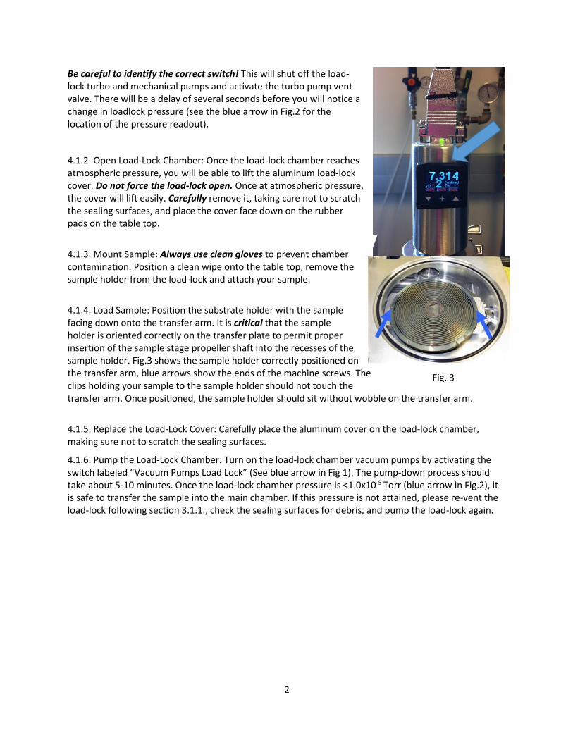
4.1.7. Open the Viewport Shutter: Referring to Fig.4, unlock the rotary actuator for the viewport shutter by loosening the locking screw with one hand while holding the indexed rotation knob in place with the other hand. Using the rotation knob, carefully rotate the shutter counterclockwise until it just clears the viewport. Lock the rotary actuator.
4.1.8. Position the Linear, Rotary Sample Stage:
Inside the main vacuum chamber, the sample
holder is transferred to a linear, rotary stage. This
is accomplished by engaging a propeller shape at the bottom of the stage with
the three-pronged recess on the sample holder. Using a flashlight, identify the
propeller shape by looking through the viewport. Referring to Fig.5, locate the
linear (up/down) transfer mechanism of the stage (red arrow), and the actuator
that allows rotary motion of the stage (blue arrow). Before transferring the
sample holder into the main chamber it is critical that you verify the height of
the propeller shape. If it is positioned too low, the transfer arm will hit the
linear, rotary stage. The stage is at the correct (minimum) height for sample
transfer when the top of the upper black plate of the linear transfer mechanism
aligns with 25 on the scale (red arrow in Fig.5). Always look through the
viewport to observe the action of any joystick movement.
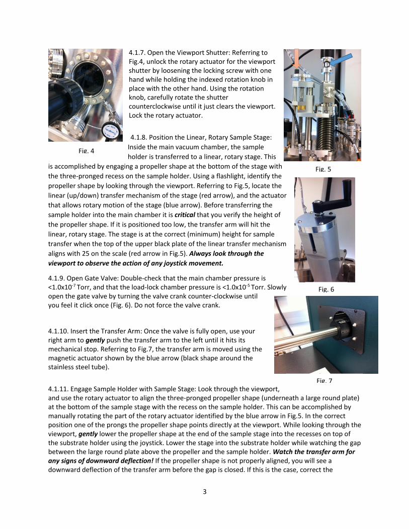
4.1.9. Open Gate Valve: Double-check that the main chamber pressure is <1.0x10⁻⁷ Torr, and that the load-lock chamber pressure is <1.0x10⁻⁵ Torr. Slowly open the gate valve by turning the valve crank counter-clockwise until you feel it click once (Fig. 6). Do not force the valve crank.
4.1.10. Insert the Transfer Arm: Once the valve is fully open, use your right arm to gently push the transfer arm to the left until it hits its mechanical stop. Referring to Fig.7, the transfer arm is moved using the magnetic actuator shown by the blue arrow (black shape around the stainless steel tube).
4.1.11. Engage Sample Holder with Sample Stage: Look through the viewport, and use the rotary actuator to align the three-pronged propeller shape (underneath a large round plate) at the bottom of the sample stage with the recess on the sample holder. This can be accomplished by manually rotating the part of the rotary actuator identified by the blue arrow in Fig.5. In the correct position one of the prongs the propeller shape points directly at the viewport. While looking through the viewport, gently lower the propeller shape at the end of the sample stage into the recesses on top of the substrate holder using the joystick. Lower the stage into the substrate holder while watching the gap between the large round plate above the propeller and the sample holder. Watch the transfer arm for any signs of downward deflection! If the propeller shape is not properly aligned, you will see a downward deflection of the transfer arm before the gap is closed. If this is the case, correct the
Fig. 4
Fig. 5
Fig. 6
Fig. 7
4
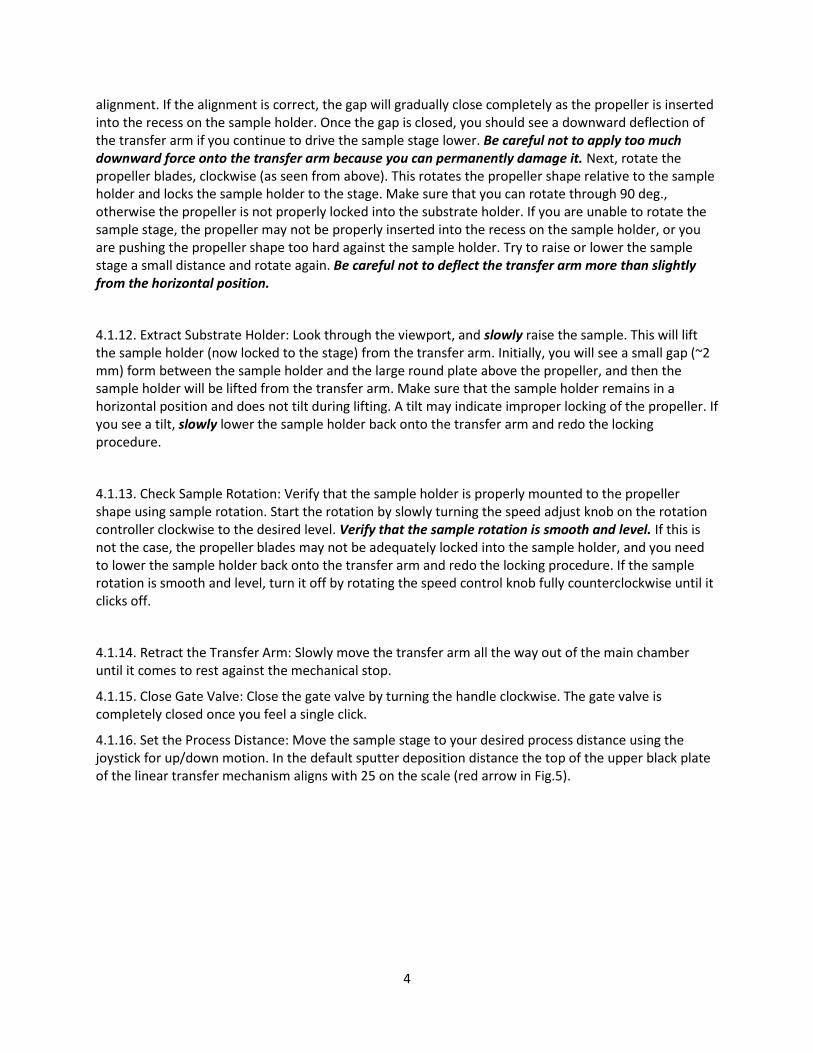
alignment. If the alignment is correct, the gap will gradually close completely as the propeller is inserted into the recess on the sample holder. Once the gap is closed, you should see a downward deflection of the transfer arm if you continue to drive the sample stage lower. Be careful not to apply too much downward force onto the transfer arm because you can permanently damage it. Next, rotate the propeller blades, clockwise (as seen from above). This rotates the propeller shape relative to the sample holder and locks the sample holder to the stage. Make sure that you can rotate through 90 deg., otherwise the propeller is not properly locked into the substrate holder. If you are unable to rotate the sample stage, the propeller may not be properly inserted into the recess on the sample holder, or you are pushing the propeller shape too hard against the sample holder. Try to raise or lower the sample stage a small distance and rotate again. Be careful not to deflect the transfer arm more than slightly from the horizontal position.
4.1.12. Extract Substrate Holder: Look through the viewport, and slowly raise the sample. This will lift the sample holder (now locked to the stage) from the transfer arm. Initially, you will see a small gap (~2 mm) form between the sample holder and the large round plate above the propeller, and then the sample holder will be lifted from the transfer arm. Make sure that the sample holder remains in a horizontal position and does not tilt during lifting. A tilt may indicate improper locking of the propeller. If you see a tilt, slowly lower the sample holder back onto the transfer arm and redo the locking procedure.
4.1.13. Check Sample Rotation: Verify that the sample holder is properly mounted to the propeller shape using sample rotation. Start the rotation by slowly turning the speed adjust knob on the rotation controller clockwise to the desired level. Verify that the sample rotation is smooth and level. If this is not the case, the propeller blades may not be adequately locked into the sample holder, and you need to lower the sample holder back onto the transfer arm and redo the locking procedure. If the sample rotation is smooth and level, turn it off by rotating the speed control knob fully counterclockwise until it clicks off.
4.1.14. Retract the Transfer Arm: Slowly move the transfer arm all the way out of the main chamber until it comes to rest against the mechanical stop.
4.1.15. Close Gate Valve: Close the gate valve by turning the handle clockwise. The gate valve is completely closed once you feel a single click.
4.1.16. Set the Process Distance: Move the sample stage to your desired process distance using the joystick for up/down motion. In the default sputter deposition distance the top of the upper black plate of the linear transfer mechanism aligns with 25 on the scale (red arrow in Fig.5).
5
4.2. Sputter Deposition During sample transfer, the main chamber vacuum pressure will temporarily rise. Once the transfer arm has been returned to the load-lock and the gate valve has been shut, the main chamber vacuum pressure will quickly recover. When the pressure has returned to <2.0x10⁻⁷
Torr deposition can be started.
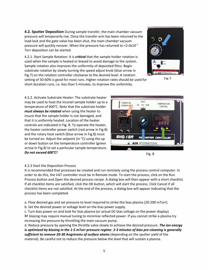
4.2.1. Start Sample Rotation: It is critical that the sample holder rotation is used when the sample is heated or biased to avoid damage to the system. Sample rotation also improves the uniformity of deposited films. Begin substrate rotation by slowly turning the speed adjust knob (blue arrow in Fig.7) on the rotation controller clockwise to the desired level. A rotation setting of 50-60% is good for most runs. Higher rotation rates should be used for short duration runs, i.e. less than 5 minutes, to improve the uniformity.
4.2.2. Activate Substrate Heater: The substrate heater may be used to heat the Inconel sample holder up to a temperature of 600°C. Note that the substrate holder must always be rotated when using the heater to insure that the sample holder is not damaged, and that it is uniformly heated. Location of the heater controls are indicated in Fig. 8. To operate the heater, the heater controller power switch (red arrow in Fig.8) and the rotary heat switch (blue arrow in Fig.8) must be turned on. Adjust the setpoint (in °C) using the up or down button on the temperature controller (green arrow in Fig.8) to set a particular sample temperature. Do not exceed 600°C!
4.2.3 Start the Deposition Process It is recommended that processes be created and run remotely using the process control computer. In order to do this, the VAT controller must be in Remote mode. To start the process, click on the Run Process button and Open the desired process recipe. A dialog box will then appear with a short checklist. If all checklist items are satisfied, click the OK button, which will start the process. Click Cancel if all checklist items are not satisfied. At the end of the process, a dialog box will appear indicating that the process has been completed. a. Flow desired gas and set pressure to level required to strike the bias plasma (20-200 mTorr). b. Set the desired power or voltage level on the bias power supply. c. Turn bias power on and look for bias plasma (or actual DC bias voltage on the power display). RF biasing may require manual tuning to minimize reflected power. If you cannot strike a plasma try increasing the pressure by throttling the main vacuum pump. d. Reduce pressure by opening the throttle valve slowly to achieve the desired pressure. The ion energy is optimized by biasing in the 1-5 mTorr pressure regime. 2-3 minutes of bias pre-cleaning is generally sufficient to remove 20-30 Angstroms of surface atoms (depending on the sputter yield of the material). Be careful not to reduce the pressure below the level that will sustain a plasma.
Fig 7
Fig. 8
6
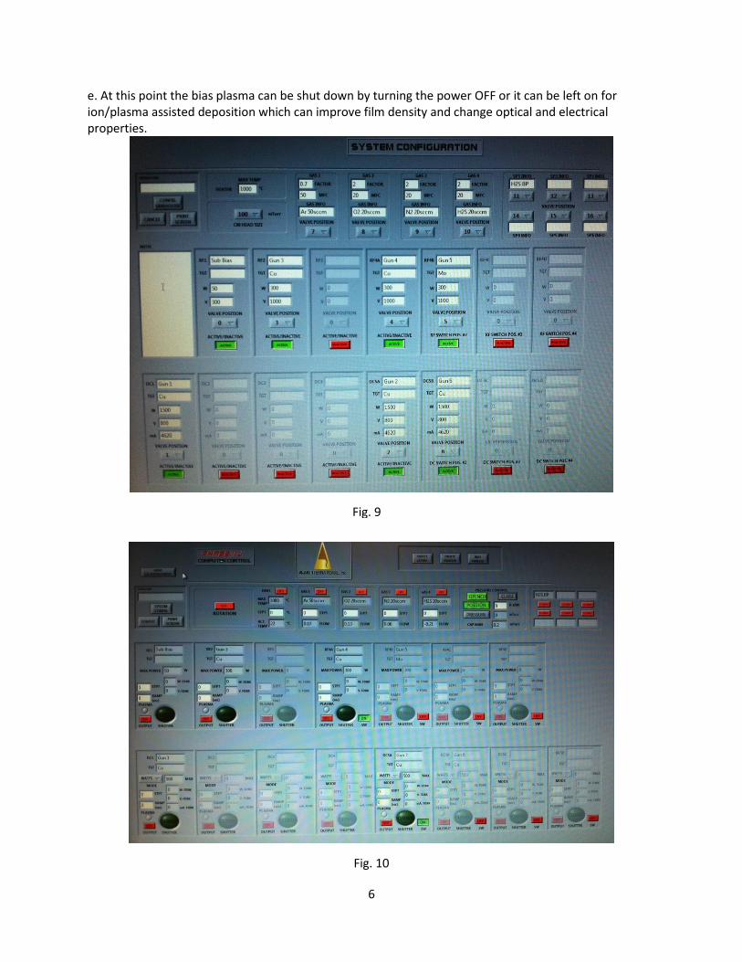
e. At this point the bias plasma can be shut down by turning the power OFF or it can be left on for ion/plasma assisted deposition which can improve film density and change optical and electrical properties.
Fig. 9
Fig. 10

7
4.2. 5. Turn off the Sample Heater: Lower the heater setpoint to 25°C using the down button on the temperature controller (green arrow in Fig.8). Turn the rotary heat switch (blue arrow in Fig.8) to “OFF”. Wait until the temperature on the temperature controller display indicates <75°C.
4.2.6. Turn off the Sample Rotation: Once the temperature has dropped to below 75°C, turn off the sample rotation by rotating the speed control knob (red arrow in Fig.7) fully counterclockwise until it clicks off. Do not stop the sample rotation before the sample temperature has dropped to less than 75°C!
4.3. Sample Unloading
4.3.1. Open Gate Valve: Verify that BOTH the load-lock chamber pressure (Fig.2) and main chamber pressure are <1.0x10⁻⁵ Torr. Slowly open the gate valve by turning the valve crank counterclockwise until you feel it click once.
4.3.2. Insert the Transfer Arm: Once the valve is fully open, use your right arm to gently push the transfer arm to the left until it hits its mechanical stop.
4.3.3. Return Sample Holder to the Sample Stage: Look through the viewport, and use the rotary actuator to align the sample holder with the transfer arm. Referring to section 4.1.11, the sample holder is properly aligned when the heads of two of the machine screws for sample clips will drop into two round cut-outs on the transfer arm (blue arrows in Fig.3) once the sample holder is lowered onto the transfer arm. The clips holding your sample to the sample holder also should be positioned so that they don’t touch the transfer arm. You can rotate the sample holder by using the part of the rotary actuator identified by the blue arrow in Fig.5. While looking through the viewport, gently lower the sample holder onto the transfer arm using the joystick. Watch the small gap (~2 mm) between the sample holder and the larger round plate immediately above the propeller shape. When the sample holder
Fig. 11

8
begins to rest on top of the transfer arm, the gap will begin to close as you continue to lower the sample stage. Make sure that the sample holder is properly positioned on top of the transfer arm when the gap begins to close; if not reposition the sample holder. Once the gap is closed, you will begin to push on the end of the transfer arm as you continue to lower the sample stage. This will cause the transfer arm to deflect downwards. Watch the transfer arm for any signs of downward deflection! Be careful not to apply too much downward force onto the transfer arm because you can permanently damage it. Next, rotate the propeller blades. counterclockwise (as seen from above). This unlocks the propeller shape from the sample holder. Make sure that you can rotate, otherwise the propeller is not properly unlocked from the substrate holder. If you are unable to rotate the sample stage, you possibly are pushing the propeller shape too hard against the sample holder. Try to raise the sample stage a small distance and rotate again. Be careful not to deflect the transfer arm more than slightly from the horizontal position. Note that you may need to rotate manually (see blue arrow in Fig.5) in order to properly unlock the propeller shape from the sample holder.
4.3.4. Extract Sample Stage: Look through the viewport, and slowly raise the sample stage. This operation should raise the propeller shape at the end of the sample stage away from the sample holder which stays behind on the transfer arm. Make sure that the sample holder remains in a horizontal position on the transfer arm and does not tilt during lifting.
4.3.5. Retract the Transfer Arm: Slowly move the transfer arm all the way out of the main chamber until it comes to rest against the mechanical stop.
4.3.6. Close Gate Valve: Close the gate valve by turning the handle clockwise. The gate valve is completely closed once you feel a single click.
4.3.7. Vent Load-Lock Chamber: Vent the load-lock chamber by turning off the load-lock turbo pump power switch labeled “Vacuum Pumps Load Lock” (See blue arrow in Fig 1). Be careful to identify the correct switch! This will shut off the load-lock turbo and mechanical pumps and activate the turbo pump vent valve. There will be a delay of several seconds before you will notice a change in loadlock pressure.
4.3.8. Open Load-Lock Chamber: Once the load-lock chamber reaches atmospheric pressure, you will be able to lift the aluminum load-lock cover (Fig.2). Do not force the load-lock open. Once at atmospheric pressure, the cover will lift easily. Carefully remove it, taking care not to scratch the sealing surfaces, and place the cover face down on the rubber pads on the table top.
4.3.9. Remove Sample: Always use clean gloves when handling the sample holder to prevent chamber contamination.
4.3.10. Return the Sample Holder to the Load-Lock: Position the substrate holder with the sample facing down onto the transfer arm. It is critical that the sample holder is oriented correctly on the transfer plate to permit proper insertion of the sample stage propeller shaft into the recesses of the sample holder.
4.3.11. Replace the Load-Lock Cover: Carefully place the aluminum cover on the load-lock chamber, making sure not to scratch the sealing surfaces.
4.3.12. Pump the Load-lock Chamber: Turn on the load-lock chamber vacuum pumps by activating the switch labeled “Vacuum Pumps Load Lock”. Please verify that the load-lock chamber pressure reaches <1.0x10⁻⁵ Torr (Fig.2) before you leave the system.
9
4.4 Sample Heating
Before operating the process, the heater controller will need to be in REMOTE mode. To do this,
I Switching the Heater Controller Between Local and Remote Mode
1. Power on the heater controller, and turn the green switch in the off position.
2. On the PID controller, press the SCROLL and DOWN arrow buttons (leftmost and rightmost buttons) one time. You should see SET on the display.
3. Repeatedly press the SCROLL button until you see SPMD on the display. Use the arrow buttons to select Pv2 for remote operation. (SP1.2 for local operation).
4. Press both arrow buttons at the same time to return to the main display. The heater controller is now configured to be operated by the PhaseIIJ software.
II Set the heating temp and duration time at Remote Mode
1. Open the Create Layers screen by clicking the Create Layers button near the top center of the screen.
2. On the left hand side of the screen you will see a section that pertains to the heater. Enter 300 C into the Heat STPT (setpoint) box.
3. If temperature ramping is required, the desired ramp may be entered into the °C/sec box.
4. Enter in the desired time you would like to maintain the 300 C setpoint in the box labeled Soak Time. In your situation you will enter 03:00:00 (3 hours).
5. Though not required for SiC heaters you can select Substrate Rotation ON if desired.
6. Save the layer by clicking Save. A dialog box will pop up requesting you to name the layer. Name the layer and click OK.
7. Exit the Create Layers screen.
8. Near the top of the screen select Create Process.
9. A list of every layer created will appear on one side of the screen. Locate the heating layer you just created and select it using the mouse. Now, click Add near the center of the screen. This adds the layer to the new process you are creating.
10. Click Save. Name the process. Click OK. Exit the Create Process screen.
III Tuning the SiC Heater
1. Be sure that the high temperature Inconel substrate holder is in place before proceeding.
2. With the high temperature substrate holder in place and the LOCAL/REMOTE parameter set toSP1.2, dial in the desired temperature tuning setpoint using the UP and DOWN arrows. 300C is a generally good place to start.
3. Press the SCROLL and DOWN arrow buttons simultaneously three times until you see A_t on the display.
4. Press and hold the SCROLL button for 3 seconds. The thermocouple readback should now be blinking on the display.

10
5. Turn the green switch on the heater controller to the ON position. Allow a few minutes for the autotune function to complete. You will know it has completed when the display stops blinking.
6. Turn the green switch to the OFF position.
7. The controller can now be returned to remote operation following the instructions from the previous section