Embed Size (px)
Citation preview
QUALITY MANAGEMENT BRANCH
STANDARD OPERATING PROCEDURES
FOR
THE VERIFICATION AND CALIBRATION OF RELATIVE HUMIDITY DEVICES
Standards Laboratory SOP 005
First edition
MONITORING AND LABORATORY DIVISION
MARCH 2014
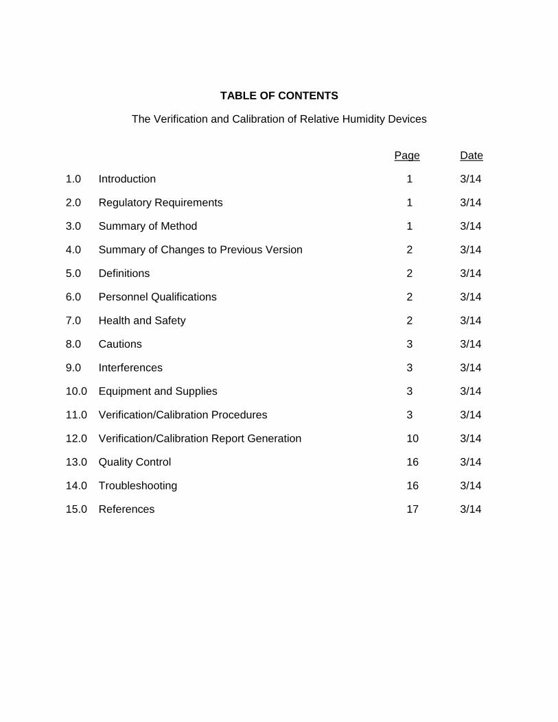
TABLE OF CONTENTS
The Verification and Calibration of Relative Humidity Devices
Page Date
1.0 Introduction 1 3/14
2.0 Regulatory Requirements 1 3/14
3.0 Summary of Method 1 3/14
4.0 Summary of Changes to Previous Version 2 3/14
5.0 Definitions 2 3/14
6.0 Personnel Qualifications 2 3/14
7.0 Health and Safety 2 3/14
8.0 Cautions 3 3/14
9.0 Interferences 3 3/14
10.0 Equipment and Supplies 3 3/14
11.0 Verification/Calibration Procedures 3 3/14
12.0 Verification/Calibration Report Generation 10 3/14
13.0 Quality Control 16 3/14
14.0 Troubleshooting 16 3/14
15.0 References 17 3/14
Standards Laboratory SOP 005 Verification/Calibration of Relative Humidity Devices
Revision 0, March 2014 Page 1 of 17
1.0 Introduction
This procedure will provide National Institute of Standards and Technology traceable verifications and calibrations for relative humidity (RH) sensors and those devices used to verify or calibrate RH sensors used in the field or laboratory. RH values from 20% to 90% can be evaluated. Hand held Digital RH meters and Analog RH sensors are acceptable for verification or calibration.
2.0 Regulatory Requirements
There are no direct State or federal regulations pertaining to the verification or calibration of RH devices. However,
U.S. Environmental Protection Agency (U.S. EPA) Quality Assurance Handbook for Air Pollution Measurement Systems, Volume IV: Meteorological Measurements, does provide the following guidance. For RH field devices, U.S. EPA recommends semiannual calibrations and that the calibrations be subject to the following acceptance criteria, dependent on the program:
• State and Local Air Monitoring Stations: ± 10% RH • Prevention of Significant Deterioration; National Core Network:
± 7% RH • Photochemical Assessment Monitoring Stations: ± 5% RH
In addition, U.S. EPA’s Quality Assurance Guidance Document 2.12 (Monitoring PM2.5 in Ambient Air Using Designed Reference or Class I Equivalent Methods) recommends quarterly calibrations of weighing room hygrometers with ± 2% acceptance criteria. The RH calibration transfer standards are recommended to be calibrated annually using the same acceptance criteria (± 2%).
3.0 Summary of Method
A candidate RH device is compared against a reference standard at five different points spread evenly throughout the instrument’s range. If the comparison meets the verification criteria, a verification report is issued and no adjustments or corrections are needed before using the data from the display of the candidate device. If an adequate coefficient of determination (R2) is developed from comparing the candidate device to
Standards Laboratory SOP 005 Verification/Calibration of Relative Humidity Devices
Revision 0, March 2014 Page 2 of 17
the reference standard (R2 ≥ 0.999), a calibration correction equation is also provided. A client may choose to use this calibration formula to correct the candidate’s display to improve the accuracy of the readings. If the candidate RH device is unable to meet the verification criteria, a re- test is performed to confirm the failure. If the failure is confirmed, the candidate device is returned to the customer for repair or replacement. For RH devices used in any environment (laboratory or field), the verification criteria is ± 2% RH at each point. For RH devices only used in the field, the verification criteria is ± 5% RH at each point. If a client chooses to correct the candidate device display, a valid calibration correction formula is provided when R2 ≥ 0.999.
4.0 Summary of Changes to Previous Version Not Applicable 5.0 Definitions
• Calibration – establishes a correction formula to be used to adjust or correct the display of the candidate instrument. This is determined through a comparison of the candidate instrument to a known, or reference standard.
• Verification – establishes comparability of a candidate instrument to
a known, or reference standard; the output of candidate instrument is not corrected based upon the results of the verification procedure.
6.0 Personnel Qualifications
Before new personnel perform this procedure, one or more weeks of training from Standards Laboratory staff is required. Subsequent to this, new personnel need to be able to demonstrate competency in performing this procedure without any assistance.
7.0 Health and Safety
• Due to the weight of the GE Humilab Relative Humidity Generator/Calibrator (Humilab) system, do not attempt to move.
Standards Laboratory SOP 005 Verification/Calibration of Relative Humidity Devices
Revision 0, March 2014 Page 3 of 17 8.0 Cautions
• Clean up any spilled water before plugging the unit into the wall outlet.
• Make sure that the power to the unit is turned off before adding
water.
• Care should be taken when inserting the RH sensor into the chamber to avoid damaging the sensor.
• The chilled mirror components are delicate. Therefore, the Humilab
should be handled with extreme care. 9.0 Interferences
Operating the Humilab outside the temperature range of 20 °C to 30 °C will affect the response time.
10.0 Equipment and Supplies
• GE Humilab Relative Humidity Generator (Reference Standard)
• Thermo Scientific Laboratory Temperature Control Unit
• Vaisala Pressure/Temperature/Relative Humidity Meter
• RH Report Spreadsheet
• RH Verification Report
11.0 Verification/Calibration Procedures (Five-Point Relative Humidity
Test)
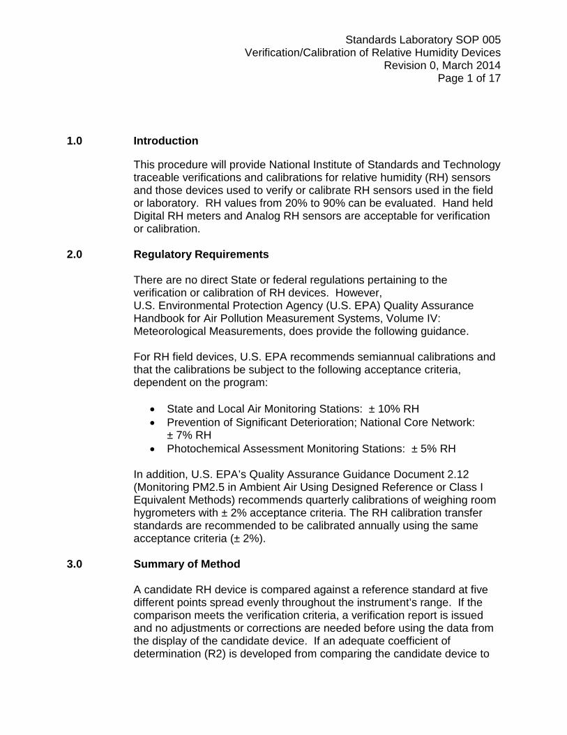
11.1 Power up the Humilab by pressing the power button on the back of the unit. Allow 1 hour before starting a test. See Figure 1.
Standards Laboratory SOP 005 Verification/Calibration of Relative Humidity Devices
Revision 0, March 2014 Page 4 of 17
Figure 1: Power Button
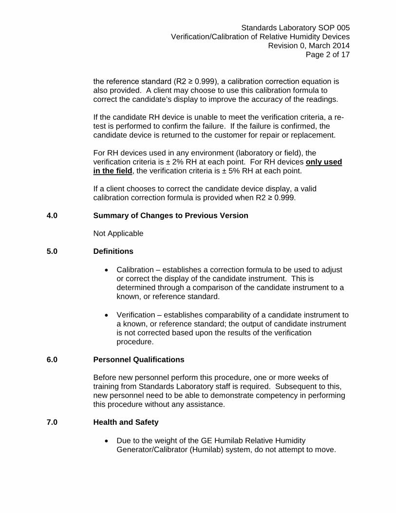
Note: The Humilab’s chamber environment sits inside a water bath. It is important that the Thermo Temperature Control Unit’s temperature and the temperature inside the chamber environment be within ± 1°C of each other before starting a test.
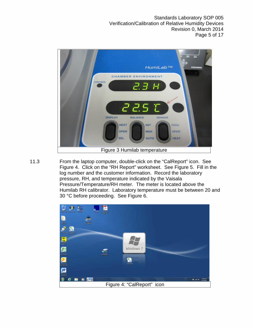
11.2 Power on the Thermo Temperature Control Unit and press the “enter” button (Figure 2). If the “Internal Temp.” on the temperature control unit is within ± 1°C of the temperature indicated on the Humilab (Figure 3), proceed to the next step. If they are not within 1°C, set the Thermo Temperature Control Unit’s internal temperature so that it is within ± 1°C of temperature indicated on the Humilab.
Figure 2: Enter button
Standards Laboratory SOP 005 Verification/Calibration of Relative Humidity Devices
Revision 0, March 2014 Page 5 of 17
Figure 3 Humilab temperature
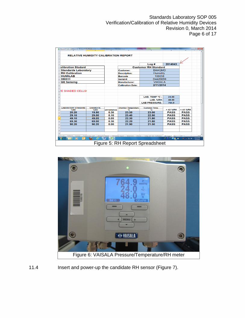
11.3 From the laptop computer, double-click on the “CalReport” icon. See
Figure 4. Click on the “RH Report” worksheet. See Figure 5. Fill in the log number and the customer information. Record the laboratory pressure, RH, and temperature indicated by the Vaisala Pressure/Temperature/RH meter. The meter is located above the Humilab RH calibrator. Laboratory temperature must be between 20 and 30 °C before proceeding. See Figure 6.
Figure 4: “CalReport” icon
Standards Laboratory SOP 005 Verification/Calibration of Relative Humidity Devices
Revision 0, March 2014 Page 6 of 17
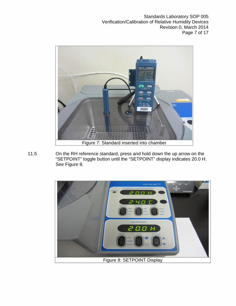
Figure 5: RH Report Spreadsheet
Figure 6: VAISALA Pressure/Temperature/RH meter
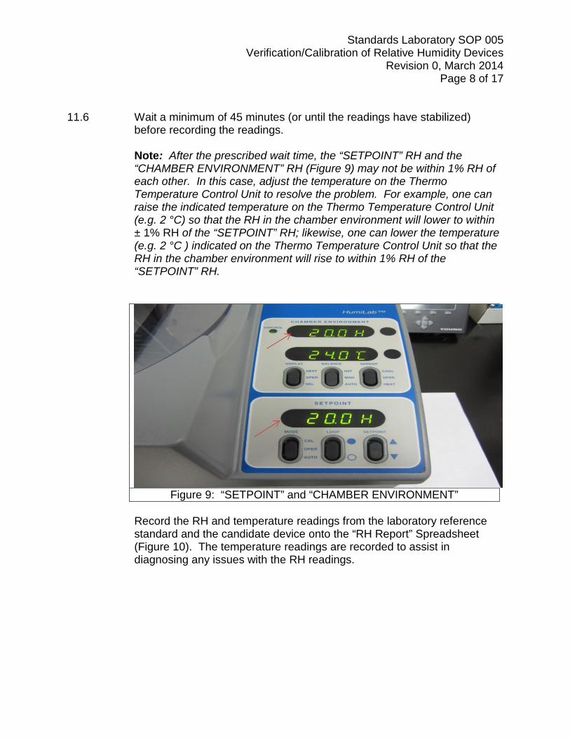
11.4 Insert and power-up the candidate RH sensor (Figure 7).
Standards Laboratory SOP 005 Verification/Calibration of Relative Humidity Devices
Revision 0, March 2014 Page 7 of 17
Figure 7: Standard inserted into chamber
11.5 On the RH reference standard, press and hold down the up arrow on the
“SETPOINT” toggle button until the “SETPOINT” display indicates 20.0 H. See Figure 8.
Figure 8: SETPOINT Display
Standards Laboratory SOP 005 Verification/Calibration of Relative Humidity Devices
Revision 0, March 2014 Page 8 of 17 11.6 Wait a minimum of 45 minutes (or until the readings have stabilized)
before recording the readings. Note: After the prescribed wait time, the “SETPOINT” RH and the
“CHAMBER ENVIRONMENT” RH (Figure 9) may not be within 1% RH of each other. In this case, adjust the temperature on the Thermo Temperature Control Unit to resolve the problem. For example, one can raise the indicated temperature on the Thermo Temperature Control Unit (e.g. 2 °C) so that the RH in the chamber environment will lower to within ± 1% RH of the “SETPOINT” RH; likewise, one can lower the temperature (e.g. 2 °C ) indicated on the Thermo Temperature Control Unit so that the RH in the chamber environment will rise to within 1% RH of the “SETPOINT” RH.
Figure 9: “SETPOINT” and “CHAMBER ENVIRONMENT”
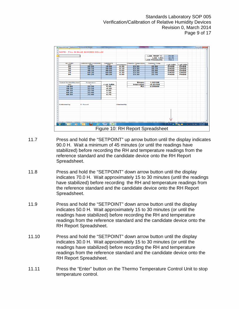
Record the RH and temperature readings from the laboratory reference
standard and the candidate device onto the “RH Report” Spreadsheet (Figure 10). The temperature readings are recorded to assist in diagnosing any issues with the RH readings.
Standards Laboratory SOP 005 Verification/Calibration of Relative Humidity Devices
Revision 0, March 2014 Page 9 of 17
Figure 10: RH Report Spreadsheet
11.7 Press and hold the “SETPOINT” up arrow button until the display indicates
90.0 H. Wait a minimum of 45 minutes (or until the readings have stabilized) before recording the RH and temperature readings from the reference standard and the candidate device onto the RH Report Spreadsheet.
11.8 Press and hold the “SETPOINT” down arrow button until the display
indicates 70.0 H. Wait approximately 15 to 30 minutes (until the readings have stabilized) before recording the RH and temperature readings from the reference standard and the candidate device onto the RH Report Spreadsheet.
11.9 Press and hold the “SETPOINT” down arrow button until the display
indicates 50.0 H. Wait approximately 15 to 30 minutes (or until the readings have stabilized) before recording the RH and temperature readings from the reference standard and the candidate device onto the RH Report Spreadsheet.
11.10 Press and hold the “SETPOINT” down arrow button until the display
indicates 30.0 H. Wait approximately 15 to 30 minutes (or until the readings have stabilized) before recording the RH and temperature readings from the reference standard and the candidate device onto the RH Report Spreadsheet.
11.11 Press the “Enter” button on the Thermo Temperature Control Unit to stop temperature control.
Standards Laboratory SOP 005 Verification/Calibration of Relative Humidity Devices
Revision 0, March 2014 Page 10 of 17
12.0 Verification/Calibration Report Generation 12.1 If the difference between the reference standard and candidate device is
± 2% RH at each RH set point, a verification report can be issued for the candidate RH device for use in a laboratory or field.
12.2 If the difference between the reference standard and candidate device is
± 5% RH at each RH set point (but not within ± 2% RH at one or more set points), a verification report can be issued for the candidate RH device for use only in the field.
12.3 If the candidate’s RH device meets the appropriate criteria above, proceed to the next step. If the candidate device does not meet either of these criteria, a retest is performed to confirm the failure. If the failure is confirmed, inform the customer of the failure and proceed with a Standard Failure Notification report.
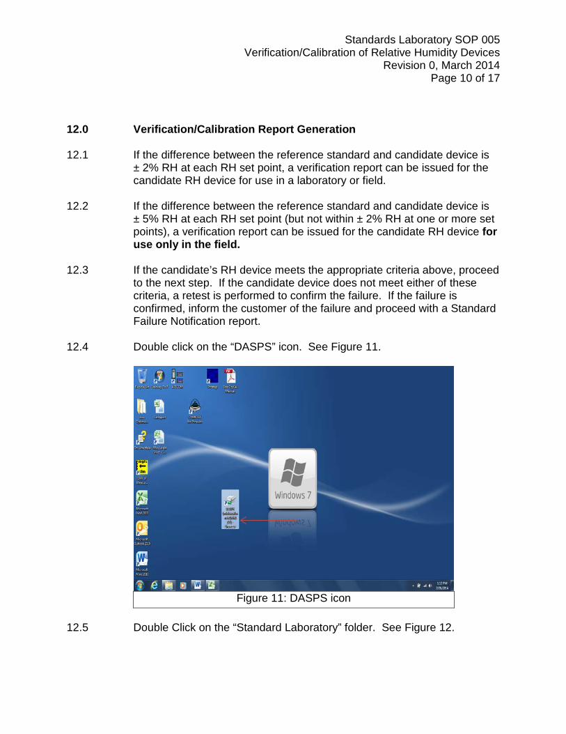
12.4 Double click on the “DASPS” icon. See Figure 11.
Figure 11: DASPS icon
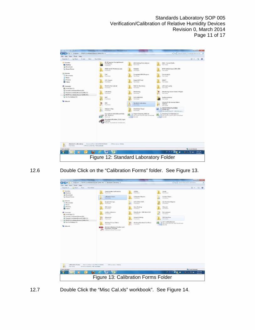
12.5 Double Click on the “Standard Laboratory” folder. See Figure 12.
Standards Laboratory SOP 005 Verification/Calibration of Relative Humidity Devices
Revision 0, March 2014 Page 11 of 17
Figure 12: Standard Laboratory Folder
12.6 Double Click on the “Calibration Forms” folder. See Figure 13.
Figure 13: Calibration Forms Folder
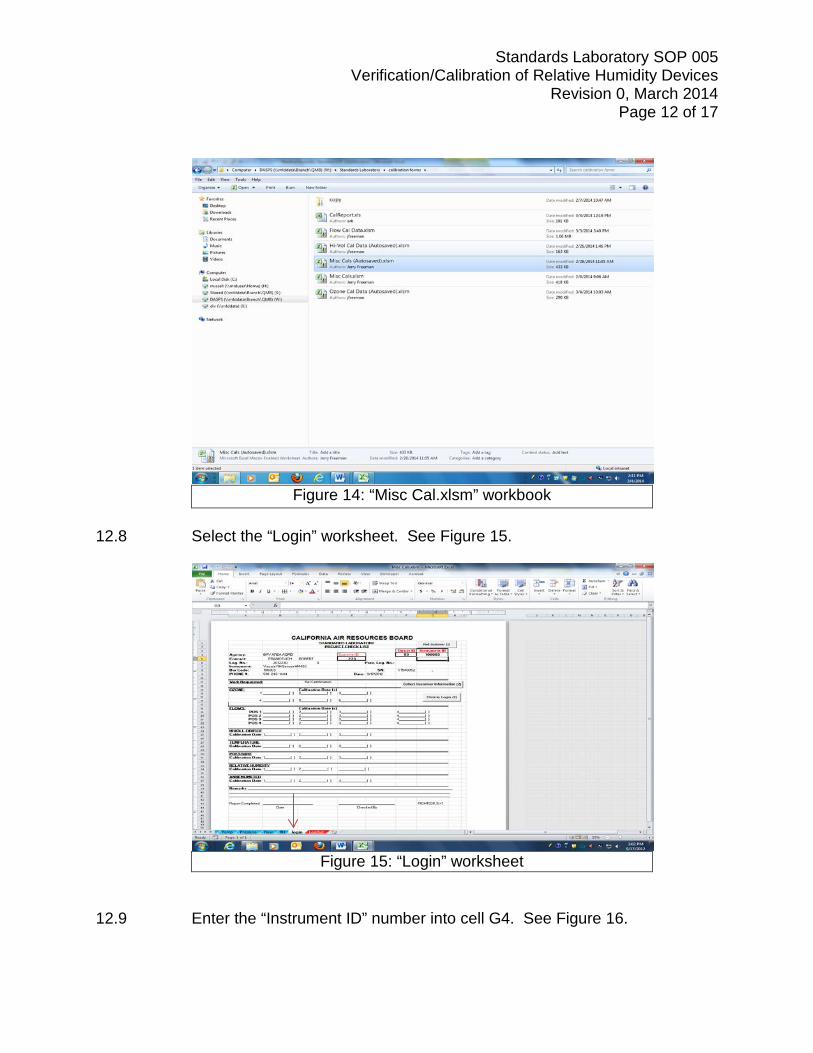
12.7 Double Click the “Misc Cal.xls” workbook”. See Figure 14.
Standards Laboratory SOP 005 Verification/Calibration of Relative Humidity Devices
Revision 0, March 2014 Page 12 of 17
Figure 14: “Misc Cal.xlsm” workbook
12.8 Select the “Login” worksheet. See Figure 15.
Figure 15: “Login” worksheet
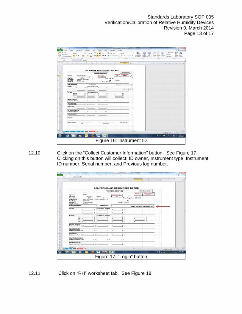
12.9 Enter the “Instrument ID” number into cell G4. See Figure 16.
Standards Laboratory SOP 005 Verification/Calibration of Relative Humidity Devices
Revision 0, March 2014 Page 13 of 17
Figure 16: Instrument ID
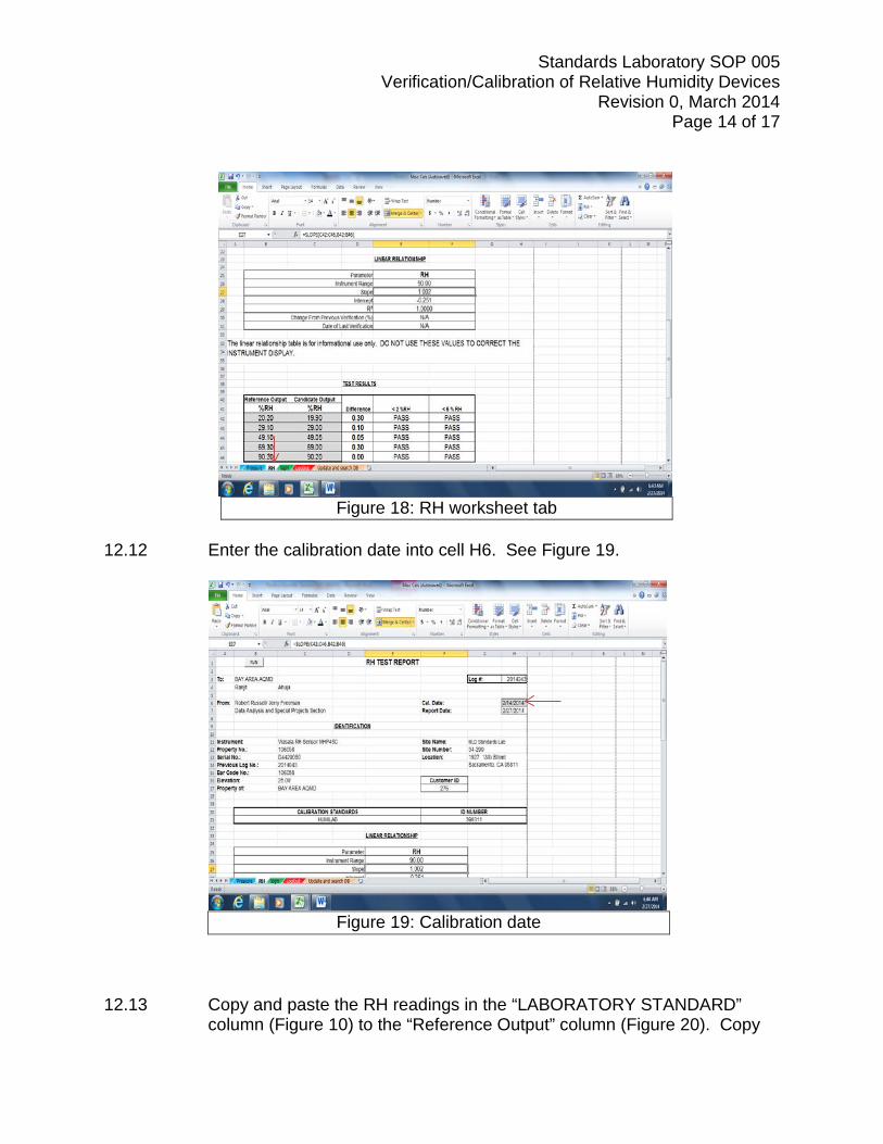
12.10 Click on the “Collect Customer Information” button. See Figure 17.
Clicking on this button will collect: ID owner, Instrument type, Instrument ID number, Serial number, and Previous log number.
Figure 17: “Login” button
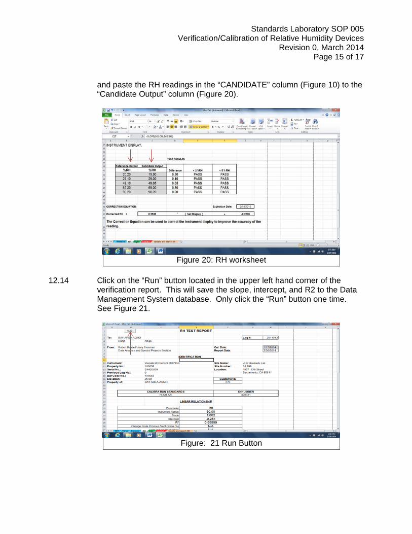
12.11 Click on “RH” worksheet tab. See Figure 18.
Standards Laboratory SOP 005 Verification/Calibration of Relative Humidity Devices
Revision 0, March 2014 Page 14 of 17
Figure 18: RH worksheet tab
12.12 Enter the calibration date into cell H6. See Figure 19.
Figure 19: Calibration date
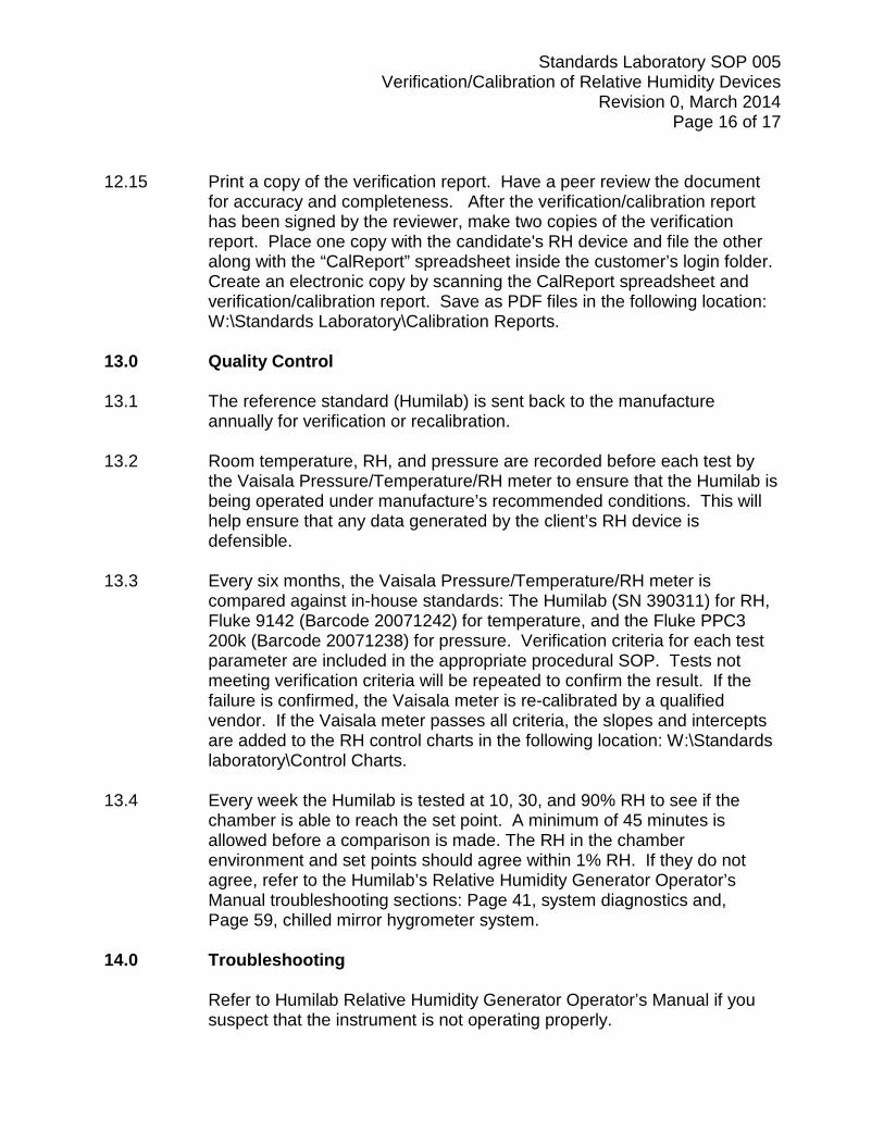
12.13 Copy and paste the RH readings in the “LABORATORY STANDARD”
column (Figure 10) to the “Reference Output” column (Figure 20). Copy
Standards Laboratory SOP 005 Verification/Calibration of Relative Humidity Devices
Revision 0, March 2014 Page 15 of 17
and paste the RH readings in the “CANDIDATE” column (Figure 10) to the “Candidate Output” column (Figure 20).
Figure 20: RH worksheet
12.14 Click on the “Run” button located in the upper left hand corner of the
verification report. This will save the slope, intercept, and R2 to the Data Management System database. Only click the “Run” button one time. See Figure 21.
Figure: 21 Run Button
Standards Laboratory SOP 005 Verification/Calibration of Relative Humidity Devices
Revision 0, March 2014 Page 16 of 17 12.15 Print a copy of the verification report. Have a peer review the document
for accuracy and completeness. After the verification/calibration report has been signed by the reviewer, make two copies of the verification report. Place one copy with the candidate's RH device and file the other along with the “CalReport” spreadsheet inside the customer’s login folder. Create an electronic copy by scanning the CalReport spreadsheet and verification/calibration report. Save as PDF files in the following location: W:\Standards Laboratory\Calibration Reports.
13.0 Quality Control 13.1 The reference standard (Humilab) is sent back to the manufacture
annually for verification or recalibration. 13.2 Room temperature, RH, and pressure are recorded before each test by
the Vaisala Pressure/Temperature/RH meter to ensure that the Humilab is being operated under manufacture’s recommended conditions. This will help ensure that any data generated by the client’s RH device is defensible.
13.3 Every six months, the Vaisala Pressure/Temperature/RH meter is
compared against in-house standards: The Humilab (SN 390311) for RH, Fluke 9142 (Barcode 20071242) for temperature, and the Fluke PPC3 200k (Barcode 20071238) for pressure. Verification criteria for each test parameter are included in the appropriate procedural SOP. Tests not meeting verification criteria will be repeated to confirm the result. If the failure is confirmed, the Vaisala meter is re-calibrated by a qualified vendor. If the Vaisala meter passes all criteria, the slopes and intercepts are added to the RH control charts in the following location: W:\Standards laboratory\Control Charts.
13.4 Every week the Humilab is tested at 10, 30, and 90% RH to see if the
chamber is able to reach the set point. A minimum of 45 minutes is allowed before a comparison is made. The RH in the chamber environment and set points should agree within 1% RH. If they do not agree, refer to the Humilab’s Relative Humidity Generator Operator’s Manual troubleshooting sections: Page 41, system diagnostics and,
Page 59, chilled mirror hygrometer system. 14.0 Troubleshooting
Refer to Humilab Relative Humidity Generator Operator’s Manual if you suspect that the instrument is not operating properly.
Standards Laboratory SOP 005 Verification/Calibration of Relative Humidity Devices
Revision 0, March 2014 Page 17 of 17 15.0 References
• U.S. EPA Quality Assurance Handbook Volume II, Sec.12.
• U.S. HumiLab Relative Humidity Generator Operator’s Manual
• U.S. EPA Quality Assurance Handbook Volume IV: Meteorological Measurements
• U.S. EPA Quality Assurance Guidance Document 2.12 (Monitoring
PM2.5 in Ambient Air Using Designed Reference or Class I Equivalent Methods)