Embed Size (px)
Citation preview

American FiberCement Corporation
1 These guidelines represent an abbreviated illustration for proper installation of Cembrit Cover, Patina, Solid and Transparent architectural panels in a ventilated rain screen application. Additional guidelines for interior applications, hidden adhesive attachment, sealing, and weather barrier attachment can be found at www.americanfibercement.com.
S U S T A I N A B L E S O L U T I O N S
Note: The online copy of the Installation Guidelines obtained at www.americanfibercement.com supersedes any printed copy.
Architectural Panels
Standard Installation Guidelines 1
Steel Profiles with Rivets
Rainscreen Application — 8 mm Panels

Preventing thermal bridgesAs the insulating material is on the outside of the structural wall, it can easily be mounted without interruptions caused by floor slabs. In this way, any thermal bridges that occur at each floor slab can be prevented. These thermal bridges are also the cause of surface condensation that may result in fungus growth.
Dissipating heat from the sunThe ventilated rainscreen cladding system has a cooling effect when temperatures outside are high. Most of the sun’s rays are reflected away from the building. Heat passing through the exterior wall panel is partially dissipated by the ventilating effect of the air space between the exterior cladding panel and the structural wall. Any residual heat managing to penetrate buildings is very minor.
RainscreenArchitectural wall-cladding panels act as a rainscreen on the outside of the building and keep the structural wall absolutely dry. The air space connected to the outside air evacuates water and humidity that might have penetrated behind the wall-cladding panels through its horizontal or vertical joints. This water will never reach the load-bearing wall and/or the thermal insulation.
Protecting the basic structure and load-bearing wall against temperature variationsIn view of the fact that the insulation material is applied to the outside of the building, changes in temperature are very minor compared with those found in conventional constructions where insulation is applied on the interior. This principle works in summer and winter, in both hot and cold climates.
Prevention of internal condensationInsulation material can be applied to the outside of the structural wall because it is protected effectively by the architectural exterior wall panel. Because of differences in vapor pressure and temperature passing through the wall, condensation has been shown to occur close to the ventilated area and not in the structural wall itself. As a result, the ventilating effect is easily sufficient to dry out the thermal insulating material.
AFCC MIG-2- S 03/2021 2 Printed in USA
Construction Practices
Rain Screen Cladding
Panels exposed to weather (rain, sun)
may only be assembled vertically. Soffit
applications not exposed to weather are allowed.
7. Jobsite storage: n Keep material laying flat, under cover, dry and
protected with a waterproof tarp. n Transport material on edge. n Using a microfiber cloth, brush off any material
dust generated by drilling or cutting prior to installation.
n Do not use the shipping crates or pallets containing the fiber cement panels as a work surface. Keep panels dust-free.
8. For field cuts and drilling, use carbide or diamond blades /bits and slower turning/feed rates. AFCC offers saw blades and drill bits.
9. All Cover, Solid and Transparent field-cut edges and field-drilled holes must be sealed with Cembrit Edge Sealer. See Cembrit Edge Sealer Instructions found on AFCC's website.
1. Air space at top and bottom of building or wall termination to be 20 mm (3⁄4") to facilitate airflow from out behind the panels. Do not block vertical airflow at windows, doors, eaves, or at the base of the building. Airflow needs to be continuous from bottom to top so there is air movement behind each panel. For walls over 60 feet high, the ventilated cavity between rear of panels and exterior wall should be increased to 30 mm (11⁄4"). Vertical air flow behind the fiber cement panels is a critical necessity in rainscreen constructions.
2. For areas that receive moderate to high snowfall, panels must terminate 6 to 12 inches above grade line based on expected snow build-up.
3. A metal drip edge may be used at window heads, door heads and the panel base, but it must not restrict airflow (3⁄4").
4. Install panels from top of building to bottom.5. For straight walls, start panel installation in center
and work outward.6. For walls with inside corners, start installation there
and work across wall.

Profile Attachment — illustrated
�1"Building
Wrap
ExteriorWall
AFC Cladding����� ���
20mm
10.25
4.8
16 8
4.9
10.5 mm8 mm
AFCC MIG-2- S 03/2021 3 Printed in USA
fig. D-2 — Exterior insulation, when vertical profiles are attached to horizontal profiles affixed to wall.
fig. D-1A —Vertical profiles are typically “Z” channels or “Hat” channels.
Hat channel can be attached with the crown facing in or out, depending on fastener spacing and the visibility of the profile through the joint.
Building wrap per AFCC. Weather and UV resistant. Check local codes for proper placement.
fig. H — Astro Rivet® with fixed cylinder
fig. J — “Hat” or “Z” channels and vertical joint. (G90 and Powder Coated “Z” channels offered by AFCC.)
For centering pilot hole in profile for Fixed Points and Gliding Points.
Can be vertically affixed directly to wall if there is no exterior insulation, provided sheathing has adequate screw-holding strength; ( 3⁄4" plywood sheathing is recommended).
fig. I — Centralizing drill bit
Options for building wrap placement
Horizontal member fastened into studs
For wall assemblies utilizing exterior sheathing with low screw-holding strength, a two-layer attachment system may be required. (See fig. D-1B)
fig. D-1B

4.9
16
11
8
ø4.8 mm
Panel
Tape
Profile
Rivet4.9
16
8.3
8
10.2
5
ø4.8 mm
Fastener
AFC CladdingPanel 1
Panel 2
SteelProfile
20mm20mm
10mm
9.5 mm
9.5 mm
➡
h
v
in. (mm)
h : 11⁄2 – 6 (40 – 150)v : 23⁄4 – 6 (70 – 150)
Ventilated Rainscreen Application
AFCC MIG-2- S 03/2021 4 Printed in USA
1. Architect / Engineer / Contractor to design and build structurally sound, water-tight exterior wall. • Substructure Horizontal Straightness Tolerance: ± 3.0 mm per 2 m (± 0.0625" per 42") • Substructure Vertical Straightness Tolerance: ± 0.5 mm per 600mm (± 0.0625" per 75")
2. Attach profiles to exterior walls. Structural engineer to determine fastening/affixing specification, i.e. quantity and type of attachment and fasteners, based upon exterior wall construction. Attachment must support 3.2 lbs/ft2 (8 mm panel) dead load, plus design wind loads. Fasteners in profile must accommodate thermal expansion/contraction of metal and not interfere with panel application. Shortening the length of the profiles can minimize thermal expansion and contraction. It is also recommended to oversize holes at or near the tops and bottoms of the profiles while having fixed points near the center. This reduces stress in the panels.
3. Profiles for affixing panels to be a minimum of 16 gauge steel or greater, determined by building orientation / location and load factors. Depending on location and climate, a minimum of G90 or greater hot-dipped galvanized coating is recommended. Galvalume® and powder coat finishes may also be used.
4. Vertical profiles for affixing panels must be the following depth to allow for optimal air flow and water drainage:
• 19 mm ( 3⁄4") for panel runs 0–15 ft • 25 mm (1") for panel runs 15–60 ft • 32 mm (11⁄4") for panel runs 60–100 ft • 38 mm (11⁄2") for panel runs 100–150 ft
For buildings over 150 feet high, special provisions are required; check with your AFC Cladding representative.
5. Profile width at vertical joints to be ≥ 120 mm (43⁄4"), and interior center profile width to be ≥ 32 mm (11⁄4") or greater, to allow tolerances in alignment. Fixed Point — cylinder & rivet Gliding Point— cylinder & rivet
fig. E — Fixed and Gliding Points
Maximum length of steel profile ≤12 feet. Two narrower profiles (“Hat” or “Z” ≥ 11⁄4" —) may be used in place of one wide profile at vertical joints. Panel can be cantilevered 11⁄2" – 6" over edge profile so vertical joint is open. (See fig. C)
6. Profiles to be straight, plumb, level and aligned correctly on the building. For installations without exterior insulation, the metal profiles are typically hat-channels or Z-channels affixed directly to the exterior wall, provided the sheathing has adequate screw-holding strength. (See fig. J)
7. It is recommended to take field measurements before panels are cut or drilled. Field measurements verify print dimensions to ensure proper fit.
8. Spacing between vertical profiles to be ≥ 20 mm ( 3⁄4"). A joint between the vertical profiles must always coincide with a joint between the panels (fig. A). The joint is preferably continued at the same horizontal height among adjacent profiles. (Reduces stress in panels).
9. For structures with exterior insulation, follow the insulation manufacturer’s installation instructions. Horizontal metal profiles (the same depth as the exterior insulation) can be attached to the exterior wall. Vertical metal profiles are then attached to the horizontal profiles ( See fig. D-2).
Building / Structure
fig. B — Interior profile.
Affix adhesive foam tape to either or both sides of rivet. (Foam tape will compress to correct depth when panel is fastened.)
fig. Cfig. A

G G G
F
G G G
G G G
G G G
G G G
G G G
GF
G
G
FG
G
G
G
G
F
G
G
G G
G
G
G
G
G
G
G
Ventilated Rainscreen Application
AFCC MIG-2- S 03/2021 5 Printed in USA
Prepare Profile
1. Typical vertical and horizontal joints are left open and have a black background (use a black weather and UV resistant building wrap). Metal profiles visible at joint openings (vertical and horizontal) can be covered with a black UV weather resistant tape or UV weather resistant coating. Other reveal colors are possible if desired.
2. Affix adhesive foam tape (supplied by AFCC) to the profile's full length — 1 strip on either side of the rivet location or 1 strip on each side of the rivet location. At vertical joints, place 1 strip on the panels center side of the rivet location. (See fig. B)
3. Horizontal and vertical joints can be closed with profiles (21 gauge or less) if desired.
Panels
1. Panels to be Patina, Solid, Transparent or Cover.
• Patina panels have a sanding grain that must be accounted for when positioning panels. Rotating some panels 90° from the orientation of adjacent panels can result in the appearance of color shading.
2. Vertical and horizontal joints to be 10 mm (3⁄8"). This is the minimum distance between the edges of two adjacent panels, or the distance from panel edge to metal trim extrusions or structural members. (See fig. A)
3. Pre-drill holes in panel so that there are: (See figs. E, F & G )
• Two (2) fixed points per panel ( F ).• The rest of the holes are to be gliding points ( G ).• See Fixing section (and figs. F & G ) for determining
location of fixed points in each panel.
4. Diameter of the fixed point hole is to be 8.3 mm (21⁄64").
5. Diameter of the gliding point hole is to be 11 mm (7⁄16").
6. Joints between profiles must coincide with horizontal joints in the panels. Panels cannot bridge a break in the profiles. (See fig. A)
7. The pilot hole in metal profile must be in the center of both the fixed point and gliding point holes. Use a drill bit centralizing fixture (supplied by AFCC) to accomplish this geometry. Pilot hole to be 4.9 mm in diameter — use #10 drill bit (4.9149 mm). (See fig. I )
8. After first affixing the two fixed-point rivets, work from the top of the panel to the bottom to avoid damage to the panel.
Fixing
1. Rivets to be Astro Rivet (supplied by AFCC) with colored or stainless steel head with 8 mm x 11.1 mm cylinder. Shank of rivet is 4.8 mm x 20 mm long, with a 16 mm diameter head. (See fig. H )
2. Fixing pattern is typically either 16" or 24" on center horizontally (based upon metal profile spacing) and 16" to 24" on center vertically, depending upon building height, building location, design criteria/specifications, and panel/fastener location on building. Edge areas on facades and high wind load conditions require closer fixing distances. Structural engineer to determine spacings. For soffit applications, the maximum fastener spacing is 16" on center in both directions.
3. Corner rivets to be located at 40 – 150 mm horizontally and 70 – 150 mm down/up vertically from each corner of panel. (fig. C)
4. 10 mm ( 3⁄ 8") clearance is required from the edge of metal profile to pilot hole for rivet.
5. Two fixed points are required per panel. (figs. I & J )
Fixed points (for attachment to vertical profiles) are:
• Always the same height in each panel.
• As close to center of panel as possible, and then either the next adjacent point to the left or right. Be consistent in panel-to-panel location (center and left or center and right, so fixed points are at the same level horizontally for attachment to vertical profiles).
• No two fixed points on one panel can be on the same profile, and no two fixed points on two adjacent panels can be on the same profile when adjacent panels share a profile at a vertical joint.
▼ fig. G — Horizontal installation on vertical profiles
▼ fig. F — Vertical installation on vertical profiles
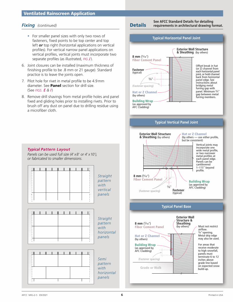
Typical Pattern LayoutPanels can be used full size (4' x 8' or 4' x 10'), or fabricated to smaller dimensions.
Semi pattern with horizontal panels
Straight pattern with horizontal panels
Straight pattern with vertical panels
Exterior Wall Structure& Sheathing (by others)
8 mm ( )Fiber Cement Panel
Offset break in hat(or Z) channel fromeach horizontal paneljoint, or hold channelback from horizontalpanel edge. Seeinstructions aboutbridging metalfurring gap withpanel. Minimum gap between metalfurring members.
Hat or Z Channel(by others)
Building Wrap(as approved byAFC Cladding)
(Fastener spacing)
Fastener(typical)
Exterior WallStructure &Sheathing(by others)
Hat or Z Channel(by others)
8 mm ( )Fiber Cement Panel
Building Wrap(as approved byAFC Cladding)
(Fastener spacing)
Grade or Walk
For areas that receive moderate to high snowfall, panels must terminate 6 to 12 inches above grade line based on expected snow build-up.
Must not restrict airflow. 3⁄4"opening.Metal drip edgemay also be used.
Exterior Wall Structure& Sheathing (by others)
Vertical joints mayincorporate onewide metal profile,or two narrowermetal profiles ateach panel edge.Panels can becantilevered1–1 beyondprofile.
Fastener(typical)
(Fastener spacing)
Building Wrap(as approved byAFC Cladding)
8 mm ( )Fiber Cement Panel
Hat or Z Channel(by others — use either profile,but be consistent)
Ventilated Rainscreen Application
AFCC MIG-2- S 03/2021 6 Printed in USA
Typical Horizontal Panel Joint
Typical Vertical Panel Joint
Typical Panel Base
• For smaller panel sizes with only two rows of fasteners, fixed points to be top center and top left or top right (horizontal applications on vertical profiles). For vertical narrow panel applications on vertical profiles, vertical joints must incorporate two separate profiles (as illustrated, fig J ).
6. Joint closures can be installed (maximum thickness of finishing profile to be .8 mm or 21 gauge). Standard practice is to leave the joints open.
7. Pilot hole for rivet in metal profile to be 4.9 mm diameter. See Panel section for drill size. (See figs. E & I )
8. Remove drill shavings from metal profile holes and panel fixed and gliding holes prior to installing rivets. Prior to brush off any dust on panel due to drilling residue using a microfiber cloth.
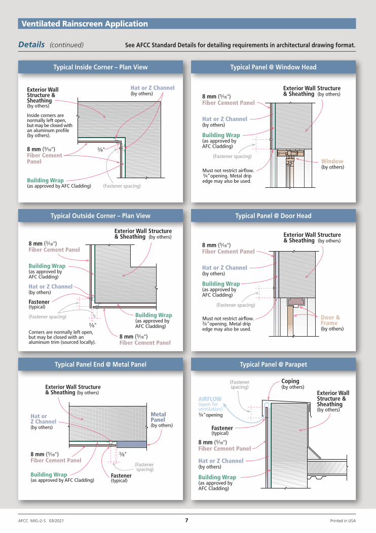
Fixing (continued) DetailsSee AFCC Standard Details for detailing requirements in architectural drawing format.
Inside corners arenormally left open,but may be closed withan aluminum profile(by others).
Exterior WallStructure &Sheathing(by others)
8 mm ( )Fiber CementPanel
Building Wrap(as approved by AFC Cladding)
Hat or Z Channel(by others)
(Fastener spacing)
Hat or Z Channel(by others)
8 mm ( )Fiber Cement Panel
Building Wrap(as approved byAFC Cladding)
(Fastener spacing)
Fastener(typical)
8 mm ( )Fiber Cement Panel
Building Wrap(as approved byAFC Cladding)
Corners are normally left open,but may be closed with analuminum trim (sourced locally).
Exterior Wall Structure& Sheathing (by others) Exterior Wall Structure
& Sheathing (by others)
Hat or Z Channel(by others)
8 mm ( )Fiber Cement Panel
Building Wrap(as approved byAFC Cladding)
(Fastener spacing)
Must not restrict airflow.3⁄4"opening. Metal dripedge may also be used.
Door &Frame(by others)
Exterior WallStructure &Sheathing(by others)
Coping(by others)
Fastener(typical)
Hat or Z Channel(by others)
8 mm ( )Fiber Cement Panel
Building Wrap(as approved byAFC Cladding)
AIRFLOW(open forventilation)3⁄4"opening
(Fastenerspacing)
Hat or Z Channel(by others)
8 mm ( )Fiber Cement Panel
Building Wrap(as approved byAFC Cladding)
(Fastener spacing)
Must not restrict airflow.3⁄4”opening. Metal drip edge may also be used.
Window(by others)
Exterior Wall Structure& Sheathing (by others)
Exterior Wall Structure& Sheathing (by others)
Fastener(typical)
(Fastenerspacing)
Building Wrap(as approved by AFC Cladding)
8 mm ( )Fiber Cement Panel
Hat orZ Channel(by others)
MetalPanel(by others)
Ventilated Rainscreen Application
AFCC MIG-2- S 03/2021 7 Printed in USA
Typical Inside Corner – Plan View
Typical Panel @ ParapetTypical Panel End @ Metal Panel
Typical Outside Corner – Plan View
Typical Panel @ Window Head
Typical Panel @ Door Head
Details (continued) See AFCC Standard Details for detailing requirements in architectural drawing format.

6901 South Pierce StreetSuite 180Littleton, CO 80128 U.S.A.
Phone: 303-972-5107 800-688-8677Fax: 303-978-0308
www.americanfibercement.com
Distributed exclusively by:
American FiberCement Corporation
Product Sustainability Statement
AFC Cladding is committed to providing the highest quality high density compressed fiber cement panels to the U.S. building markets. In order to do this, we feel it necessary to provide not only high quality products, but sustainable products that can contribute to green (LEED) building projects, which in turn benefit the environment we all live in.
AFC Cladding products currently have a potential contribution to various LEED credits including but not limited to:
Direct Contribution
Materials and Resources:u BPDO – Environmental Product Declarations
Indirect Contribution
Indoor Environmental Quality:u Thermal Comfort
Energy and Atmosphere:u Optimize Energy Performance
One of the most important sustainable attributes is the durability of AFC Cladding panels. With their long lifespan, virtually requiring no refurbishment, AFC Cladding panels can contribute to less replacement of materials and to drastically lower maintenance costs over the useful life of the building.
The Ventilated and Insulated Rainscreen Cladding (VIRSC) system, which is used to affix AFC Cladding panels to the exterior of a structure, offers many benefits and green attributes to the performance of the building envelope. Durability and resistance to moisture and mold build-up are noteworthy benefits. Equally important is its ability to accommodate external insulation.
In addition, AFC Cladding is dedicated to further research and analysis of our products to achieve additional LEED credits, and help further the cause of building sustainable and efficient buildings.
Warranty information available upon request.
For the nearest authorized fabricator, call 303-972-5107.
AFCC MIG-2- S 03/2021 8 © 2011-20, American Fiber Cement Corp., Printed in USA
Limited Warranty
American Fiber Cement Corporation (AFCC) warrants that its products are manufactured in accordance with its appli ca ble material specifications and are free from defects in materials and workmanship using AFCC’s specifica-tions as a standard. Only products which are installed and used in accordance with applicable AFCC instructions and specifications are in any way warranted by AFCC. This warranty is applicable only to claims made in writing and received by AFCC within thirty (30) days after the defect was discovered and within ten (10) years after the date of the ship-ment of the product by AFCC. All other claims are waived. If a claim is made, you must allow reason able in vestigation of the pro duct you claim is defective and you must supply samples that ade-quately demonstrate the pro blem you claim for testing by AFCC.
AFCC DISCLAIMS ALL IMPLIED WARRANTIES INCLUDING THE WARRANTY OF MERCHANTABILITY AND THE WARRANTY OF FIT NESS FOR A PARTICULAR PUR POSE. THIS LIMITED WAR RANTY PROVIDES YOUR EXCLU SIVE REMEDY AS A PURCHASER OF AFCC PRODUCTS. THIS LIMIT-ED WARRANTY MAY BE MOD IFIED OR AMENDED ONLY BY A WRIT TEN INSTRUMENT SIGNED BY A DULY AUTHORIZED REPRE SEN TATIVE OF AFCC. WITHOUT AN EXPRESS, WRITTEN AUTHORIZATION FROM AFCC, NO RETAIL ER OR DISTRIBUTOR OF AFCC PRO DUCTS HAS THE AUTHORITY TO MODIFY OR AMEND THIS LIMITED WARRANTY.
Limitation of Liability
This limited warranty is your sole and ex-clusive remedy. It is expressly understood and agreed that the limit of liability will be, at AFCC’s option, repair, re supply of a like quantity of non-defective product, or re fund of purchase price of the mate-rial. All labor and service charges which may be incur red with respect to either the original or replacement pro duct are excluded. AFCC shall have no liability except where the claim results solely from breach of AFCC’s limited warranty.
AFCC SHALL NOT BE LIABLE FOR ANY INCIDENTAL OR CON SEQUENTIAL DAMAGES. FUR THERMORE, AFCC SHALL NOT BE LIABLE FOR DAMAGE TO THE PROPERTY TO WHICH THE PRO DUCT IS APPLIED OR ITS CON-TENTS, LOSS OF TIME, PROFITS, OR ANY INCONVENIENCE ARISING OUT OF ANY BREACH OF THIS LIMITED WARRANTY OR OBLIGATIONS UNDER THIS LIMITED WARRANTY. AFCC SHALL NOT BE LIABLE FOR ANY DAM AGES WHICH ARE BASED UPON NEGLIGENCE, BREACH OF WAR RANTY, STRICT LIABILITY, OR ANY OTHER THEORY EXCEPT THE LIMITED WARRANTY SET FORTH ABOVE. INCIDENTAL AND CONSEQUENTIAL DAM AGES SHALL NOT BE RECOVERABLE EVEN IF THE REPLACEMENT REMEDY FAILS OF ITS PURPOSE OR FOR ANY OTHER REASON.