Embed Size (px)
Citation preview
GSM Association Non-confidential
Official Document TS.31 - Standard Diagnostic Logging
V3.0 Page 1 of 26
Standard Diagnostic Logging
Version 3.0
21 October 2016
This is a Non-binding Permanent Reference Document of the GSMA
Security Classification: Non-confidential
Access to and distribution of this document is restricted to the persons permitted by the security classification. This document is confidential to the
Association and is subject to copyright protection. This document is to be used only for the purposes for which it has been supplied and
information contained in it must not be disclosed or in any other way made available, in whole or in part, to persons other than those permitted
under the security classification without the prior written approval of the Association.
Copyright Notice
Copyright © 2016 GSM Association
Disclaimer
The GSM Association (“Association”) makes no representation, warranty or undertaking (express or implied) with respect to and does not accept
any responsibility for, and hereby disclaims liability for the accuracy or completeness or timeliness of the information contained in this document.
The information contained in this document may be subject to change without prior notice.
Antitrust Notice
The information contain herein is in full compliance with the GSM Association’s antitrust compliance policy.
GSM Association Non-confidential
Official Document TS.31 - Standard Diagnostic Logging
V3.0 Page 2 of 26
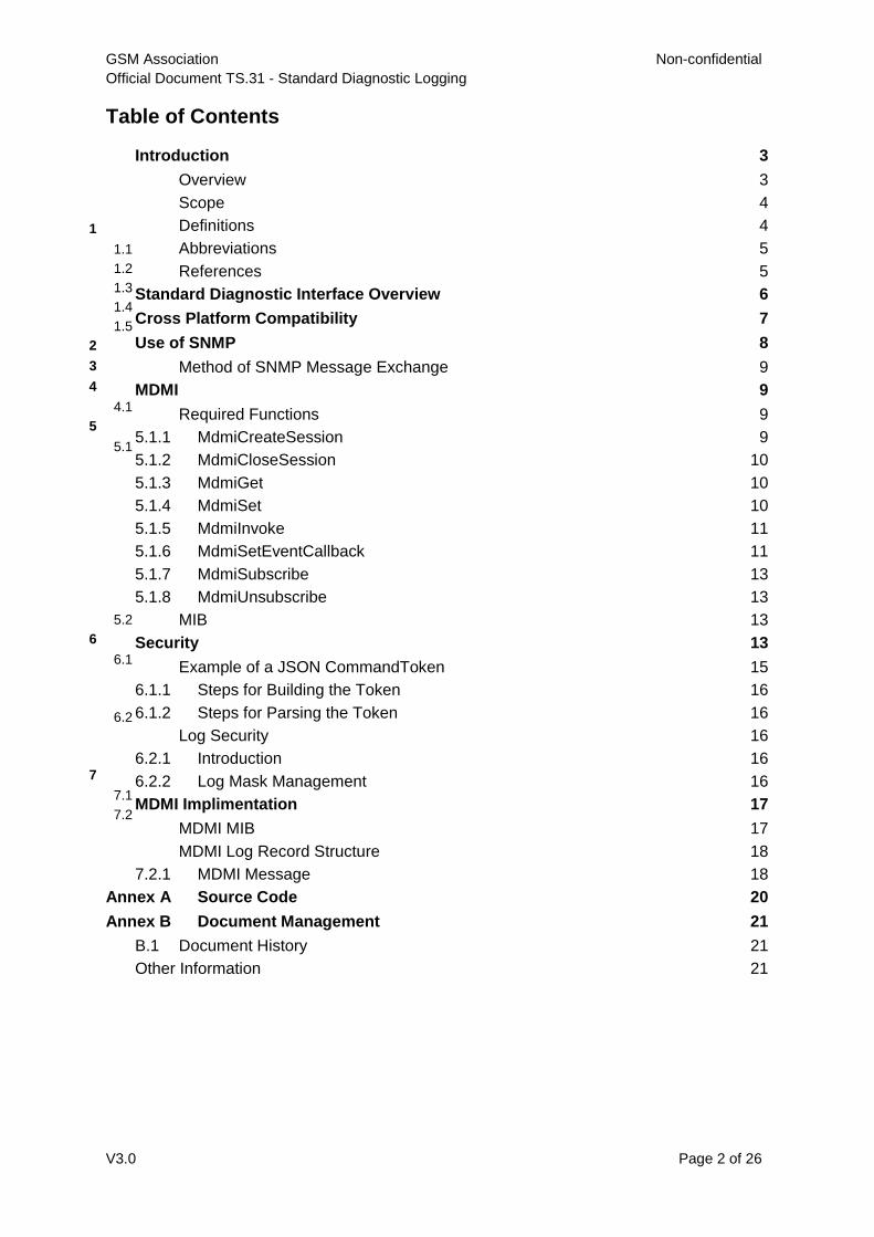
Table of Contents
Introduction 3
1
Overview 3
1.1
Scope 4
1.2
Definitions 4
1.3
Abbreviations 5
1.4
References 5
1.5
Standard Diagnostic Interface Overview 6
2
Cross Platform Compatibility 7
3
Use of SNMP 8
4
Method of SNMP Message Exchange 9
4.1
MDMI 9
5 Required Functions 9
5.15.1.1 MdmiCreateSession 9
5.1.2 MdmiCloseSession 10
5.1.3 MdmiGet 10
5.1.4 MdmiSet 10
5.1.5 MdmiInvoke 11
5.1.6 MdmiSetEventCallback 11
5.1.7 MdmiSubscribe 13
5.1.8 MdmiUnsubscribe 13
MIB 13 5.2
Security 13 6
Example of a JSON CommandToken 15 6.1
6.1.1 Steps for Building the Token 16
6.1.2 Steps for Parsing the Token 16
Log Security 16 6.2
6.2.1 Introduction 16
6.2.2 Log Mask Management 16
MDMI Implimentation 17
7
MDMI MIB 17
7.1
MDMI Log Record Structure 18
7.2
7.2.1 MDMI Message 18
Annex A Source Code 20
Annex B Document Management 21
B.1 Document History 21
Other Information 21
GSM Association Non-confidential
Official Document TS.31 - Standard Diagnostic Logging
V3.0 Page 3 of 26
Introduction
1
Overview
1.1
The purpose of this document is to provide a standardized method to log modem data and
messaging on a device, eliminating the need for tethered logging. The primary user of the
logging tool is expected to be mobile network operators.
Possible use cases are listed below:
Report the geo-location of the device and key RF parameters (RSRP, RSSI, SINR
etc.) to determine network coverage
Present geo-located events on maps to allow better call drop analysis
Capture handover statistics to debug handover issues
Report VoLTE (Voice over LTE) call statistics (e.g. Delay, Jitter and Packet Loss) to
aid in VoLTE analysis
Real time reporting on the device
Data throughput
Txpower
Cell selection
RF parameters
The operator will be able to log with any device/chipset compliant to the interface outlined in
this document by downloading a compliant application. The logs will be saved on the device
and uploaded to an operator server. This document provides the APIs (Application
Programming Interfaces) and MIB (Management Information Base) to capture the modem
and other components' log data; and the security protocol to authenticate the device before
logging can be initiated. The API source code is available on the GSMA GitHub site, the
manufacturers and application vendors are encouraged to download this source code to
implement the standard logging solution.
The API defined in this document to retrieve the modem and other components' log data are
part of the MDMI (Modem Diagnostic Monitoring Interface). Using the MDMI, the diagnostic
application will be able to retrieve information from the components being logged, such as a
KPI or a protocol message. MDMI is modelled on and is defined using a standardized
format, SNMP (Simple Network Management Protocol). As per SNMP convention, all
information retrieved from the components being logged, is passed as objects and are
defined in the MIB. There are some advantages of using this framework to define the
interface to the modem. However, MDMI diverges from the SNMP specification in several
ways. In particular, MDMI cannot be implemented by the use of SNMP tools without
additional effort.
This document is organized as follows:
Section 2 introduces the MDMI (Modem Diagnostic Monitoring Interface) and presents an
overview of how it utilizes SNMP (Simple Network Management Protocol). This overview
includes illustrations of support for multiple diagnostic feeds.
GSM Association Non-confidential
Official Document TS.31 - Standard Diagnostic Logging
V3.0 Page 4 of 26
Note: The previous version of this specification illustrated an architecture for
logging the modem component alone.
Section 3 presents architectures on the device to implement the standard diagnostic
interface
Section 4 describes how SNMP has been adapted for use in MDMI, including an overview
of the types of information that MDMI makes available, the relationships between the
different application components, and method that is used for exchanging messages.
Section 5 outlines MDMI, including the functions that must be implemented, and provides an
overview of the MIB (Management Information Base), which defines all the messages, KPIs
(Key Performance Indicators) and commands that must be made available.
Section 6 describes the Security Architecture Design for MDMI, including both the
authentication of the device required before logging can take place, and the security of the
log data. Authentication methods for both an on board tool and remote log session control
are disucssed.
Annex A References the source code location.
Annex B Document History.
Scope 1.2
The initial scope of the GSMA standard diagnostic logging interface (version 1.0) was
restricted to engineering builds for LTE and Wi-Fi only. Scope is now expanded to include
additional technologies such as eMBMS, IMS. Further expansions of the scope requires
further study.
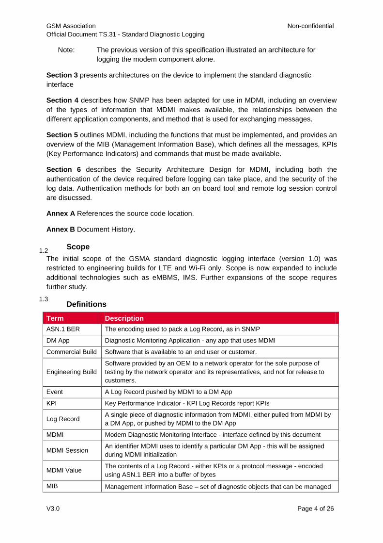
Definitions 1.3
Term Description
ASN.1 BER The encoding used to pack a Log Record, as in SNMP
DM App Diagnostic Monitoring Application - any app that uses MDMI
Commercial Build Software that is available to an end user or customer.
Engineering Build
Software provided by an OEM to a network operator for the sole purpose of
testing by the network operator and its representatives, and not for release to
customers.
Event A Log Record pushed by MDMI to a DM App
KPI Key Performance Indicator - KPI Log Records report KPIs
Log Record A single piece of diagnostic information from MDMI, either pulled from MDMI by
a DM App, or pushed by MDMI to the DM App
MDMI Modem Diagnostic Monitoring Interface - interface defined by this document
MDMI Session An identifier MDMI uses to identify a particular DM App - this will be assigned
during MDMI initialization
MDMI Value The contents of a Log Record - either KPIs or a protocol message - encoded
using ASN.1 BER into a buffer of bytes
MIB Management Information Base – set of diagnostic objects that can be managed
GSM Association Non-confidential
Official Document TS.31 - Standard Diagnostic Logging
V3.0 Page 5 of 26
Term Description
by SNMP
OID Object ID – the unique identifier for an SNMP object
Protocol Message A Log Record containing an OTA message of a particular protocol
SNMP Simple Network Management Protocol
SNMP Agent The provider of diagnostic information - in MDMI, the OEM writes a library
conforming to this requirement that acts as an SNMP agent
SNMP Manager The user of SNMP Agent - in MDMI, this would be a component of a DM app
SNMP Object A unit of diagnostic information defined in the MIB
SNMP Trap SNMP terminology for a message pushed from agent to manager - in MDMI, we
use the term "Event" synonymously
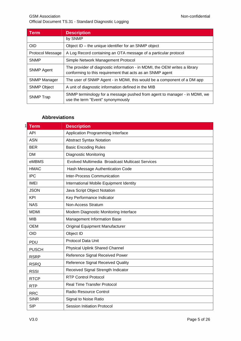
Abbreviations
1.4Term Description
API Application Programming Interface
ASN Abstract Syntax Notation
BER Basic Encoding Rules
DM Diagnostic Monitoring
eMBMS Evolved Multimedia Broadcast Multicast Services
HMAC Hash Message Authentication Code
IPC Inter-Process Communication
IMEI International Mobile Equipment Identity
JSON Java Script Object Notation
KPI Key Performance Indicator
NAS Non-Access Stratum
MDMI Modem Diagnostic Monitoring Interface
MIB Management Information Base
OEM Original Equipment Manufacturer
OID Object ID
PDU Protocol Data Unit
PUSCH Physical Uplink Shared Channel
RSRP Reference Signal Received Power
RSRQ Reference Signal Received Quality
RSSI Received Signal Strength Indicator
RTCP RTP Control Protocol
RTP Real Time Transfer Protocol
RRC Radio Resource Control
SINR Signal to Noise Ratio
SIP Session Initiation Protocol
GSM Association Non-confidential
Official Document TS.31 - Standard Diagnostic Logging
V3.0 Page 6 of 26
Term Description
SNMP Simple Network Management Protocol
SW Software
TCP Transmission Control Protocol
TLS Transport Layer Security
UDP User Datagram Protocol
UTF Unicode Transformation Format
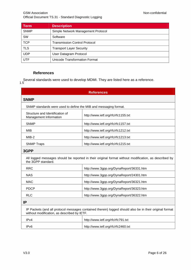
References
1.5Several standards were used to develop MDMI. They are listed here as a reference.
References
SNMP
SNMP standards were used to define the MIB and messaging format.
Structure and Identification of Management Information
http://www.ietf.org/rfc/rfc1155.txt
SNMP http://www.ietf.org/rfc/rfc1157.txt
MIB http://www.ietf.org/rfc/rfc1212.txt
MIB-2 http://www.ietf.org/rfc/rfc1213.txt
SNMP Traps http://www.ietf.org/rfc/rfc1215.txt
3GPP
All logged messages should be reported in their original format without modification, as described by the 3GPP standard.
RRC http://www.3gpp.org/DynaReport/36331.htm
NAS http://www.3gpp.org/DynaReport/24301.htm
MAC http://www.3gpp.org/DynaReport/36321.htm
PDCP http://www.3gpp.org/DynaReport/36323.htm
RLC http://www.3gpp.org/DynaReport/36322.htm
IP
IP Packets (and all protocol messages contained therein) logged should also be in their original format without modification, as described by IETF.
IPv4 http://www.ietf.org/rfc/rfc791.txt
IPv6 http://www.ietf.org/rfc/rfc2460.txt
GSM Association Non-confidential
Official Document TS.31 - Standard Diagnostic Logging
V3.0 Page 7 of 26
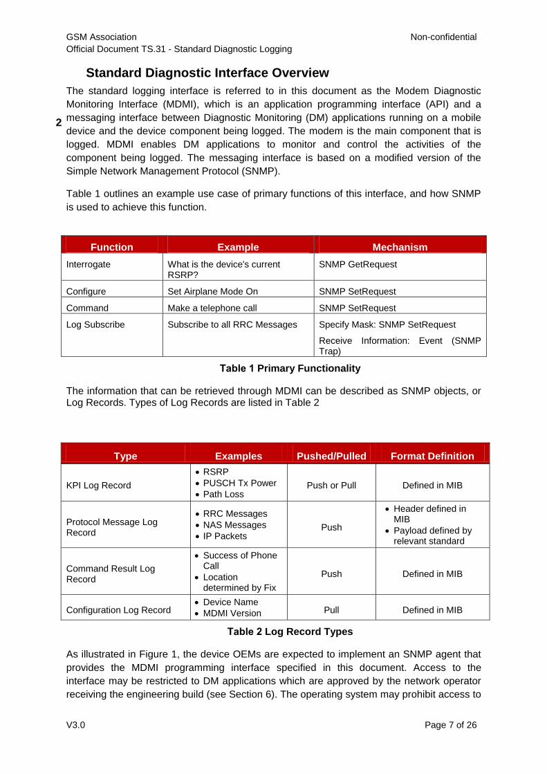
Standard Diagnostic Interface Overview
2
The standard logging interface is referred to in this document as the Modem Diagnostic
Monitoring Interface (MDMI), which is an application programming interface (API) and a
messaging interface between Diagnostic Monitoring (DM) applications running on a mobile
device and the device component being logged. The modem is the main component that is
logged. MDMI enables DM applications to monitor and control the activities of the
component being logged. The messaging interface is based on a modified version of the
Simple Network Management Protocol (SNMP).
Table 1 outlines an example use case of primary functions of this interface, and how SNMP
is used to achieve this function.
Function Example Mechanism
Interrogate What is the device's current RSRP?
SNMP GetRequest
Configure Set Airplane Mode On SNMP SetRequest
Command Make a telephone call SNMP SetRequest
Log Subscribe Subscribe to all RRC Messages Specify Mask: SNMP SetRequest
Receive Information: Event (SNMP Trap)
Table 1 Primary Functionality
The information that can be retrieved through MDMI can be described as SNMP objects, or Log Records. Types of Log Records are listed in Table 2
Type Examples Pushed/Pulled Format Definition
KPI Log Record
RSRP
PUSCH Tx Power
Path Loss Push or Pull Defined in MIB
Protocol Message Log Record
RRC Messages
NAS Messages
IP Packets Push
Header defined in MIB
Payload defined by relevant standard
Command Result Log Record
Success of Phone Call
Location determined by Fix
Push Defined in MIB
Configuration Log Record Device Name
MDMI Version Pull Defined in MIB
Table 2 Log Record Types
As illustrated in Figure 1, the device OEMs are expected to implement an SNMP agent that
provides the MDMI programming interface specified in this document. Access to the
interface may be restricted to DM applications which are approved by the network operator
receiving the engineering build (see Section 6). The operating system may prohibit access to
GSM Association Non-confidential
Official Document TS.31 - Standard Diagnostic Logging
V3.0 Page 8 of 26
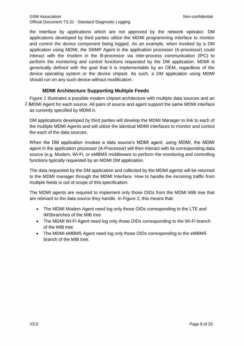
the interface by applications which are not approved by the network operator. DM
applications developed by third parties utilize the MDMI programming interface to monitor
and control the device component being logged. As an example, when invoked by a DM
application using MDMI, the SNMP Agent in the application processor (A-processor) could
interact with the modem in the B-processor via inter-process communication (IPC) to
perform the monitoring and control functions requested by the DM application. MDMI is
generically defined with the goal that it is implementable by an OEM, regardless of the
device operating system or the device chipset. As such, a DM application using MDMI
should run on any such device without modification.
MDMI Architecture Supporting Multiple Feeds
2.1
Figure 1 illustrates a possible modem chipset architecture with multiple data sources and an
MDMI Agent for each source. All pairs of source and agent support the same MDMI interface
as currently specified by MDMI.h.
DM applications developed by third parties will develop the MDMI Manager to link to each of
the multiple MDMI Agents and will utilize the identical MDMI interfaces to monitor and control
the each of the data sources.
When the DM application invokes a data source’s MDMI agent, using MDMI, the MDMI
agent in the application processor (A-Processor) will then interact with its corresponding data
source (e.g. Modem, Wi-Fi, or eMBMS middleware to perform the monitoring and controlling
functions typically requested by an MDMI DM application.
The data requested by the DM application and collected by the MDMI agents will be returned
to the MDMI manager through the MDMI Interface. How to handle the incoming traffic from
multiple feeds is out of scope of this specification.
The MDMI agents are required to implement only those OIDs from the MDMI MIB tree that
are relevant to the data source they handle. In Figure 2, this means that:
The MDMI Modem Agent need log only those OIDs corresponding to the LTE and
IMSbranches of the MIB tree
The MDMI Wi-Fi Agent need log only those OIDs corresponding to the Wi-Fi branch
of the MIB tree
The MDMI eMBMS Agent need log only those OIDs corresponding to the eMBMS
branch of the MIB tree.
GSM Association Non-confidential
Official Document TS.31 - Standard Diagnostic Logging
V3.0 Page 9 of 26
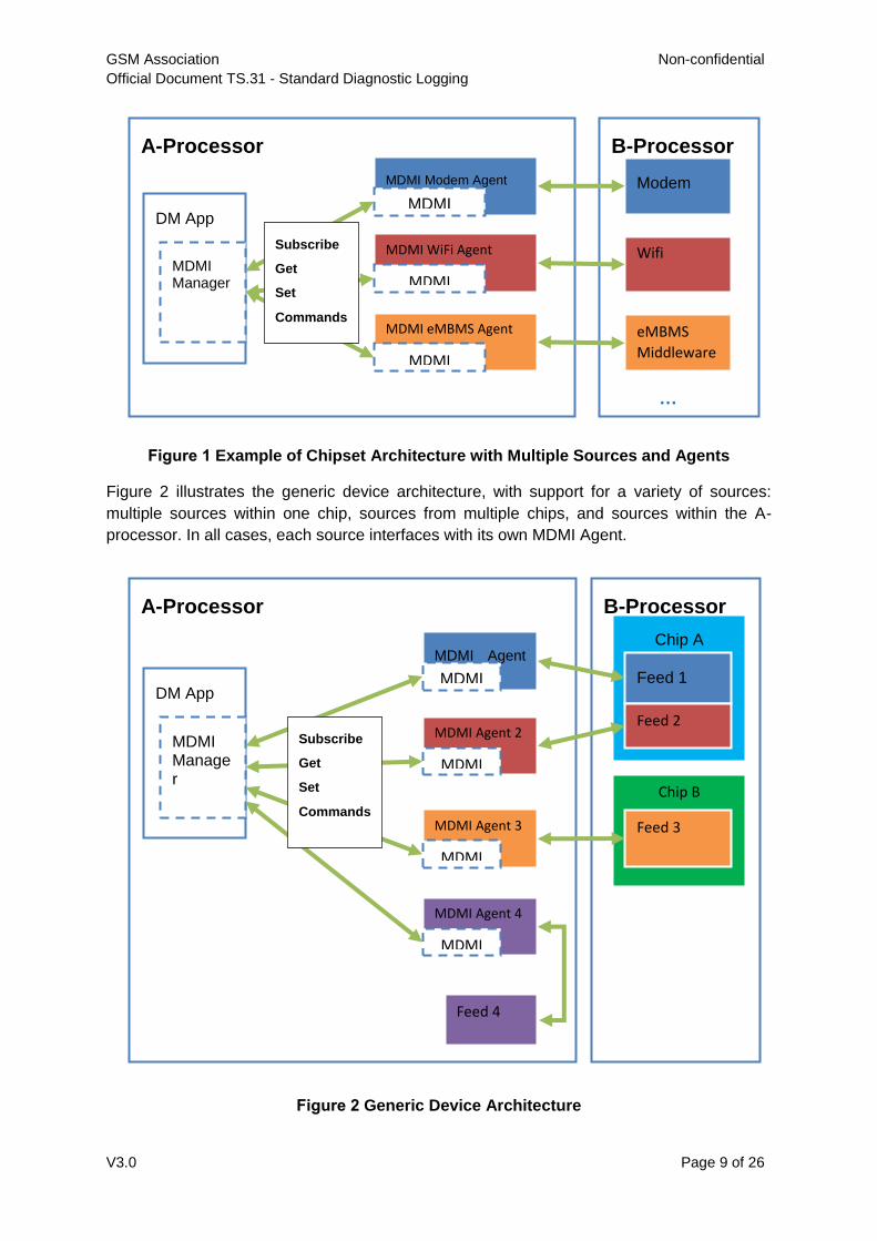
Figure 1 Example of Chipset Architecture with Multiple Sources and Agents
Figure 2 illustrates the generic device architecture, with support for a variety of sources:
multiple sources within one chip, sources from multiple chips, and sources within the A-
processor. In all cases, each source interfaces with its own MDMI Agent.
Figure 2 Generic Device Architecture
A-Processor
DM App
MDMI Manager
MDMI Modem Agent
MDMI
MDMI WiFi Agent
MDMI
MDMI eMBMS Agent
MDMI
B-Processor
Modem
Wifi
eMBMS
Middleware
Subscribe
Get
Set
Commands
… …
B-Processor
Chip B
A-Processor
DM App
MDMI Manager
MDMI Agent 1 MDMI
MDMI Agent 2
MDMI
MDMI Agent 3
MDMI
Feed 3
Chip A
Feed 1
Feed 2
MDMI Agent 4
MDMI
Feed 4
Subscribe
Get
Set
Commands
GSM Association Non-confidential
Official Document TS.31 - Standard Diagnostic Logging
V3.0 Page 10 of 26
The requirements for MDMI multiple feeds are summarized as follows:
1. Individual MDMI Agents are needed in the A-Processor for logging each data source,
whether from the A-Processor or from the B-Processor
2. Multiple data sources from a single chip in the B-Processor require separate MDMI
Agents for each feed
3. Each MDMI Agent will be implemented as unique .so libraries; however, each Agent
is required to implement the same MDMI interface, as specified in the header file
(MDMI.h)
4. The .so library implemented for each data source will only need to implement OIDs
from the MDMI MIB tree relevant to the specific data source
Designated Names for .so Files
2.2As noted above, each MDMI Agent will be implemented as unique .so libraries. These
libraries must have different names. Vendors are expected to use designated names, as
follows:
For an MDMI Agent supporting a modem: libmdmi-device.so
For an MDMI Agent supporting Wi-Fi: libmdmi-wifi.so
For an MDMI Agent supporting eMBMS: libmdmi-embms.so
The DM app will link and distinguish different feeds by the use of these names.
Cross Platform Compatibility 3
MDMI is generically defined with the goal that it is implementable by one or more chip
vendors, regardless of the device operating system or the device chipset. Consequently, a
DM application using MDMI should run on any such device without modification.
This library has been designed to make integrating a DM app onto devices as seamless as
possible. To the extent possible, the usage should be identical across devices, chipsets,
OEMs and even operating systems. However, due to underlying differences between current
mobile operating systems, some differences will be inevitable.
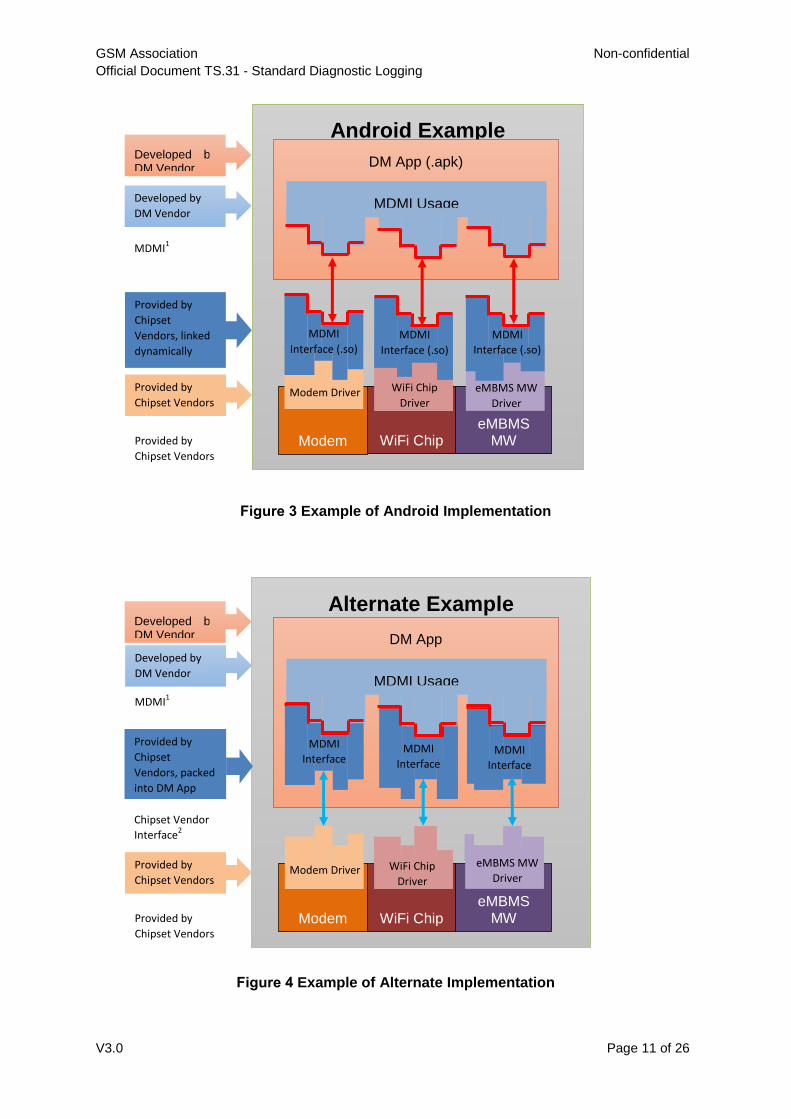
Figure 3 shows an example of an Android implementation of the architecture in Figure
1. Figure 4 shows an example of implementing the same architecture on an alternate
platform. In both operating systems, the OEM will provide a library making all the
functionality of MDMI available to a DM app. On the Android, the .so libraries will be pre-
installed on the system. A DM app, once installed, will dynamically link to the libraries to use
the functionality of MDMI. On alternate platforms, pre-installing the library may not be
possible, due to platform restrictions. The libraries will be prepared by the chipset vendors
and provided to the developer of the DM App as dll files. The dll files will be compiled directly
into the DM app. The DM App will have to be recompiled for each version of the libraries.
GSM Association Non-confidential
Official Document TS.31 - Standard Diagnostic Logging
V3.0 Page 11 of 26
Figure 3 Example of Android Implementation
Figure 4 Example of Alternate Implementation
Android Example
Modem
DM App (.apk)
WiFi Chip eMBMS
MW
MDMI
Interface (.so)
WiFi Chip
Driver
MDMI
Interface (.so)
eMBMS MW
Driver
MDMI
Interface (.so)
Modem Driver
MDMI Usage
Developed by DM Vendor
Developed by
DM Vendor
MDMI1
Provided by
Chipset
Vendors, linked
dynamically
Provided by
Chipset Vendors
Provided by
Chipset Vendors
Alternate Example
Modem
DM App
WiFi Chip eMBMS
MW
MDMI
Interface MDMI
Interface
MDMI
Interface
MDMI Usage
Developed by DM Vendor
Developed by
DM Vendor
MDMI1
Provided by
Chipset
Vendors, packed
into DM App
Provided by
Chipset Vendors
Provided by
Chipset Vendors
Modem Driver eMBMS MW
Driver WiFi Chip
Driver
Chipset Vendor
Interface2
GSM Association Non-confidential
Official Document TS.31 - Standard Diagnostic Logging
V3.0 Page 12 of 26
Use of SNMP
4
The MDMI interface is based on SNMP, in spite of their differences (notably, that the
interface is not over UDP/IP). The reason for basing the interface on SNMP is to make use
of a standardized monitoring and control interface structure. As described in Section 3, the
DM application includes the functionality of a SNMP Manager, and the MDMI module, which
provides a programming interface to extract modem information, acts as a SNMP Agent.
The desired implementation can be achieved with SNMPv1 and, only a subset of SNMPv1 is
used.
The MIB defines all log objects that are available through MDMI. These are organized
hierarchically, and each object has an OID as identifier. Some are available to be read, and
others can be both read and written. Some are available to be pushed to the DM App as
events once the DM App has subscribed to them. The MIB also defines the exact syntax of
each field in each object. The scope of these objects covers a set of KPIs and protocol
messages, as well as some basic configuration items and commands. The design is
extensible so that more KPIs, protocols and commands can be added in future releases.
Method of SNMP Message Exchange 4.1SNMP operates over UDP. MDMI replaces this with function calls in which a buffer is
passed from the DM App to the SNMP Agent and vice versa. This buffer will contain the
SNMP requests/responses encoded in the same way SNMP is encoded (ASN.1 BER
encoding scheme, see references in section 1 for more details). Both open source and
commercial libraries exist to encode and decode ASN.1, and are widely used in many other
telecommunication protocols.
An application can either pull logs from MDMI by using a "Get" message, or the application
can request that logs to be pushed to it by specifying which events should be sent from the
MDMI to the DM App. When events are to be pushed, the DM App must specify the function
MDMI will use as a pointer using MdmiSetEventCallback, and specifying the events that
are requested using MdmiSubscribe.
MDMI
5
The basics of the API are described below. Devices implementing MDMI must conform to
these definitions precisely.
Required Functions
5.1
Each required function is listed in the tables below with:
Function Name - the name of the function
Signature - the exact function signature that must be implemented
Arguments - name and explanation of the arguments passed to the function
Return Value - value returned by the function
5.1.1 MdmiCreateSession
This function creates a MDMI session that is used in subsequent MDMI calls to identify the
caller.
GSM Association Non-confidential
Official Document TS.31 - Standard Diagnostic Logging
V3.0 Page 13 of 26
Function Name MdmiCreateSession
Signature MdmiError MdmiCreateSession
(const wchar_t* address,
MdmiSession* session);
Arguments address: address of the MDMI device to open. May be ignored if the system has
only one device
session: session object that will be set upon success. This will be used by the
caller in subsequent calls to MDMI.
Return Value MDMI_NO_ERROR on success otherwise an error
5.1.2 MdmiCloseSession
This function closes the MDMI session.
Function Name MdmiCloseSession
Signature MdmiError MdmiCloseSession
(MdmiSession* session);
Arguments session: session object that will be closed. If close is succesful, the session
object is set to 0, indicating invalid session
Return Value MDMI_NO_ERROR on success otherwise an error
5.1.3 MdmiGet
This function gets the value of a specific object, as specified by that object's OID.
Function Name MdmiGet
Signature MdmiError MdmiGet
(MdmiSession session,
const MdmiObjectName* name,
MdmiValue* value);
Arguments session: identifies the session
name: OID of the value
value: value to be read. If the read is succesful, the actual value is read into
this pointer. Upon return the ownership of this pointer is transferred to caller and must be freed when no longer needed
Return Value MDMI_NO_ERROR on success otherwise an error
5.1.4 MdmiSet
This function sets the value of a specific object, as specified by that object's OID.
GSM Association Non-confidential
Official Document TS.31 - Standard Diagnostic Logging
V3.0 Page 14 of 26
Function Name MdmiSet
Signature MdmiError MdmiSet
(MdmiSession session,
const MdmiObjectName* name,
const MdmiValue* value);
Arguments session: identifies the session
name: OID of the value
value: value to be set
Return Value MDMI_NO_ERROR on success otherwise an error
5.1.5 MdmiInvoke
This function invokes a command through MDMI. Commands are defined in the MIB and
identified by an OID.
Function Name MdmiInvoke
Signature MdmiError MdmiInvoke
(MdmiSession session,
const MdmiObjectName* name,
const MdmiValue* value);
Arguments session: identifies the session
name: OID of the command to invoke
value: optional value of the command (can be null)
Return Value MDMI_NO_ERROR on success otherwise an error
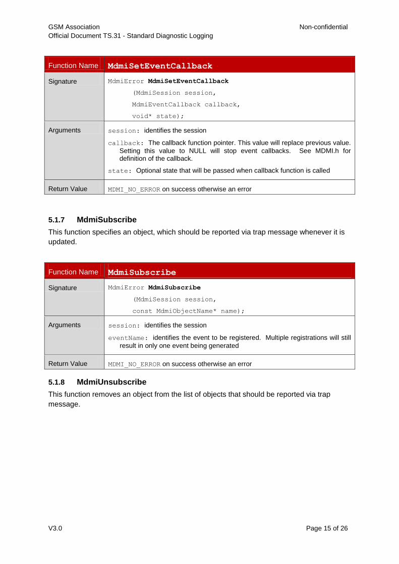
5.1.6 MdmiSetEventCallback
This function sets the call back function that will be used for pushed events.
GSM Association Non-confidential
Official Document TS.31 - Standard Diagnostic Logging
V3.0 Page 15 of 26
Function Name MdmiSetEventCallback
Signature MdmiError MdmiSetEventCallback
(MdmiSession session,
MdmiEventCallback callback,
void* state);
Arguments session: identifies the session
callback: The callback function pointer. This value will replace previous value.
Setting this value to NULL will stop event callbacks. See MDMI.h for definition of the callback.
state: Optional state that will be passed when callback function is called
Return Value MDMI_NO_ERROR on success otherwise an error
5.1.7 MdmiSubscribe
This function specifies an object, which should be reported via trap message whenever it is
updated.
Function Name MdmiSubscribe
Signature MdmiError MdmiSubscribe
(MdmiSession session,
const MdmiObjectName* name);
Arguments session: identifies the session
eventName: identifies the event to be registered. Multiple registrations will still
result in only one event being generated
Return Value MDMI_NO_ERROR on success otherwise an error
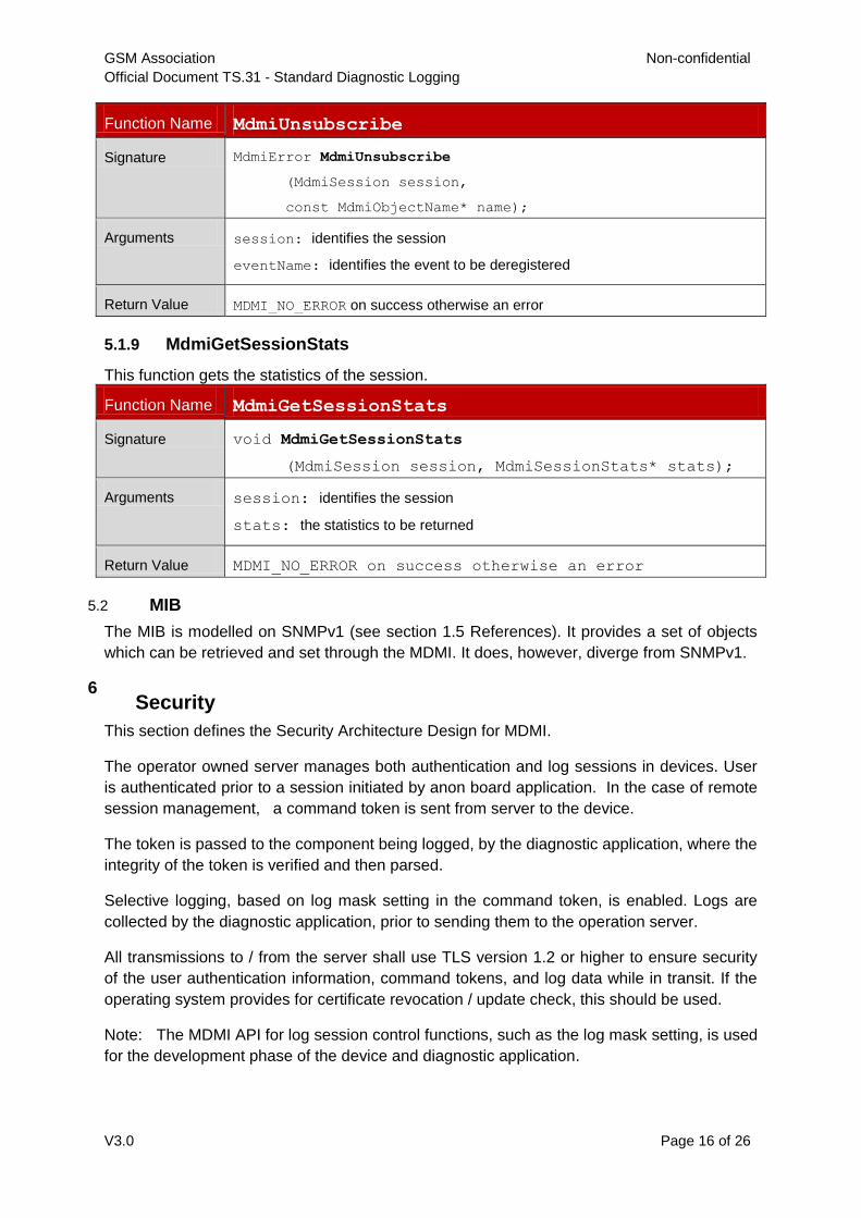
5.1.8 MdmiUnsubscribe
This function removes an object from the list of objects that should be reported via trap
message.
GSM Association Non-confidential
Official Document TS.31 - Standard Diagnostic Logging
V3.0 Page 16 of 26
Function Name MdmiUnsubscribe
Signature MdmiError MdmiUnsubscribe
(MdmiSession session,
const MdmiObjectName* name);
Arguments session: identifies the session
eventName: identifies the event to be deregistered
Return Value MDMI_NO_ERROR on success otherwise an error
5.1.9 MdmiGetSessionStats
This function gets the statistics of the session.
Function Name MdmiGetSessionStats
Signature void MdmiGetSessionStats
(MdmiSession session, MdmiSessionStats* stats);
Arguments session: identifies the session
stats: the statistics to be returned
Return Value MDMI_NO_ERROR on success otherwise an error
MIB 5.2
The MIB is modelled on SNMPv1 (see section 1.5 References). It provides a set of objects
which can be retrieved and set through the MDMI. It does, however, diverge from SNMPv1.
Security 6
This section defines the Security Architecture Design for MDMI.
The operator owned server manages both authentication and log sessions in devices. User
is authenticated prior to a session initiated by anon board application. In the case of remote
session management, a command token is sent from server to the device.
The token is passed to the component being logged, by the diagnostic application, where the
integrity of the token is verified and then parsed.
Selective logging, based on log mask setting in the command token, is enabled. Logs are
collected by the diagnostic application, prior to sending them to the operation server.
All transmissions to / from the server shall use TLS version 1.2 or higher to ensure security
of the user authentication information, command tokens, and log data while in transit. If the
operating system provides for certificate revocation / update check, this should be used.
Note: The MDMI API for log session control functions, such as the log mask setting, is used
for the development phase of the device and diagnostic application.
GSM Association Non-confidential
Official Document TS.31 - Standard Diagnostic Logging
V3.0 Page 17 of 26
1. Operating System Restrictions and Policy enforcement – Permissions and Group
ID enforcement, along with policy enforcement using SeLinux is incorporated in
devices. This is to ensure only operator authorized on board log applications have
access to the MDMI interface. Specification of group ID, permissions and policies are
operator specific.
2. User Authentication – Server validates user with login credentials (user name and
password), as supplied by user launching the application, thereby restricting only
authenticated users to log into the diagnostic system. Additional checks based on
IMEI and user's group are used to restrict devices log and reports to specific users or
user group.
3. Secure Channel – Command tokens are sent to the device from the server via a
secure channel. As noted above, the secure channel shall use TLS version 1.2 or
higher, and certificate revocation / update check shall be used if available.
4. Command Set for remote log session – JSON packets are used to define
command tokens (ON/OFF, Time to Live, Log Privilege level, Log groups). JSON
Packets are integrity protected and can be interpreted only by the modem (which has
the public key of policy certificate).
Log Data – The log mask limits the scope of the logging information. The log mask can be
set by a user or privileges enforced by the SW load. If log data cannot be transmitted to the
server immediately, it shall be stored securely on the device, in a manner such that
untrusted applications are unable to access the log data.
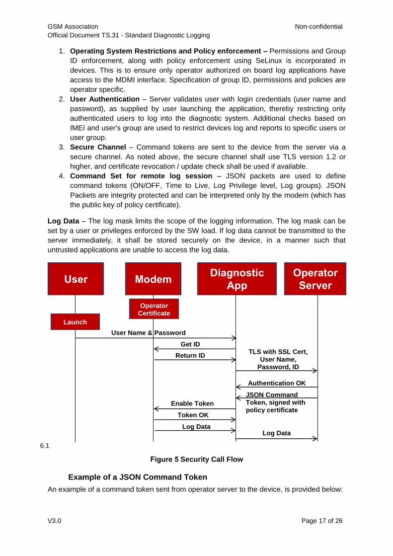
Figure 5 Security Call Flow
Example of a JSON Command Token
6.1
An example of a command token sent from operator server to the device, is provided below:
User Modem Diagnostic
App
Operator
Server
Launch
Operator Certificate
loaded
User Name & Password
Get ID
Return ID TLS with SSL Cert,
User Name, Password, ID
Authentication OK
JSON Command Token, signed with policy certificate
Enable Token
Token OK
Log Data Log Data
GSM Association Non-confidential
Official Document TS.31 - Standard Diagnostic Logging
V3.0 Page 18 of 26
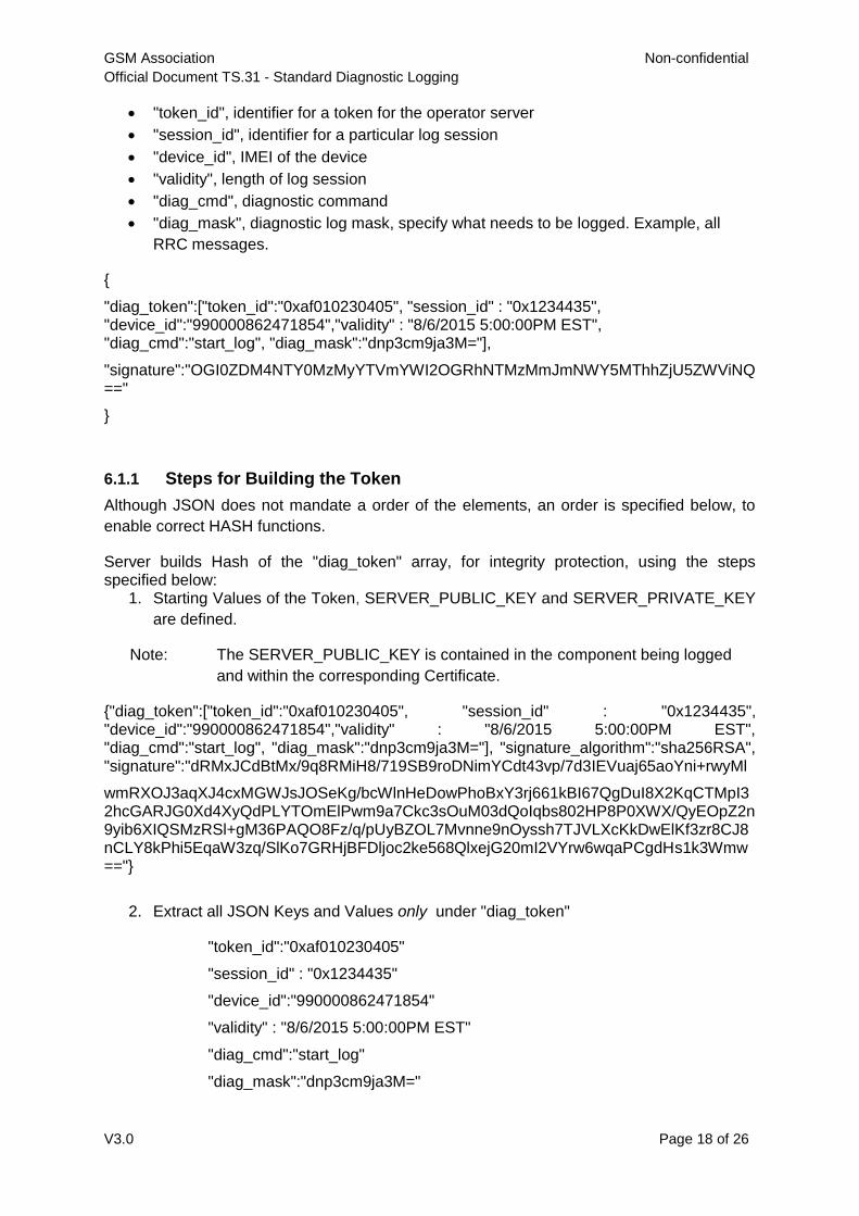
"token_id", identifier for a token for the operator server
"session_id", identifier for a particular log session
"device_id", IMEI of the device
"validity", length of log session
"diag_cmd", diagnostic command
"diag_mask", diagnostic log mask, specify what needs to be logged. Example, all
RRC messages.
{
"diag_token":["token_id":"0xaf010230405", "session_id" : "0x1234435", "device_id":"990000862471854","validity" : "8/6/2015 5:00:00PM EST", "diag_cmd":"start_log", "diag_mask":"dnp3cm9ja3M="],
"signature":"OGI0ZDM4NTY0MzMyYTVmYWI2OGRhNTMzMmJmNWY5MThhZjU5ZWViNQ=="
}
6.1.1 Steps for Building the Token
Although JSON does not mandate a order of the elements, an order is specified below, to
enable correct HASH functions.
Server builds Hash of the "diag_token" array, for integrity protection, using the steps specified below:
1. Starting Values of the Token, SERVER_PUBLIC_KEY and SERVER_PRIVATE_KEY
are defined.
Note: The SERVER_PUBLIC_KEY is contained in the component being logged
and within the corresponding Certificate.
{"diag_token":["token_id":"0xaf010230405", "session_id" : "0x1234435", "device_id":"990000862471854","validity" : "8/6/2015 5:00:00PM EST", "diag_cmd":"start_log", "diag_mask":"dnp3cm9ja3M="], "signature_algorithm":"sha256RSA", "signature":"dRMxJCdBtMx/9q8RMiH8/719SB9roDNimYCdt43vp/7d3IEVuaj65aoYni+rwyMl
wmRXOJ3aqXJ4cxMGWJsJOSeKg/bcWlnHeDowPhoBxY3rj661kBI67QgDuI8X2KqCTMpI32hcGARJG0Xd4XyQdPLYTOmElPwm9a7Ckc3sOuM03dQoIqbs802HP8P0XWX/QyEOpZ2n9yib6XIQSMzRSl+gM36PAQO8Fz/q/pUyBZOL7Mvnne9nOyssh7TJVLXcKkDwElKf3zr8CJ8nCLY8kPhi5EqaW3zq/SlKo7GRHjBFDljoc2ke568QlxejG20mI2VYrw6wqaPCgdHs1k3Wmw=="}
2. Extract all JSON Keys and Values only under "diag_token"
"token_id":"0xaf010230405"
"session_id" : "0x1234435"
"device_id":"990000862471854"
"validity" : "8/6/2015 5:00:00PM EST"
"diag_cmd":"start_log"
"diag_mask":"dnp3cm9ja3M="
GSM Association Non-confidential
Official Document TS.31 - Standard Diagnostic Logging
V3.0 Page 19 of 26
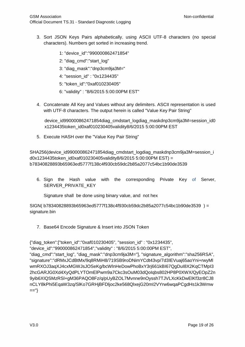
3. Sort JSON Keys Pairs alphabetically, using ASCII UTF-8 characters (no special
characters). Numbers get sorted in increasing trend.
1: "device_id":"990000862471854"
2: "diag_cmd":"start_log"
3: "diag_mask":"dnp3cm9ja3M="
4: "session_id" : "0x1234435"
5: "token_id":"0xaf010230405"
6: "validity" : "8/6/2015 5:00:00PM EST"
4. Concatenate All Key and Values without any delimiters. ASCII representation is used
with UTF-8 characters. The output herein is called "Value Key Pair String"
device_id990000862471854diag_cmdstart_logdiag_maskdnp3cm9ja3M=session_id0
x1234435token_id0xaf010230405validity8/6/2015 5:00:00PM EST
5. Execute HASH over the "Value Key Pair String"
SHA256(device_id990000862471854diag_cmdstart_logdiag_maskdnp3cm9ja3M=session_i
d0x1234435token_id0xaf010230405validity8/6/2015 5:00:00PM EST) =
b78340828893b65963ed5777f138c4f930cb59dc2b85a2077c54bc1b90de3539
6. Sign the Hash value with the corresponding Private Key of Server,
SERVER_PRIVATE_KEY
Signature shall be done using binary value, and not hex
SIGN( b78340828893b65963ed5777f138c4f930cb59dc2b85a2077c54bc1b90de3539 ) =
signature.bin
7. Base64 Encode Signature & Insert into JSON Token
{"diag_token":["token_id":"0xaf010230405", "session_id" : "0x1234435",
"device_id":"990000862471854","validity" : "8/6/2015 5:00:00PM EST",
"diag_cmd":"start_log", "diag_mask":"dnp3cm9ja3M="], "signature_algorithm":"sha256RSA",
"signature":"dRMxJCdBtMx/9q8RMiH8/719SB9roDNimYCdt43vp/7d3IEVuaj65aoYni+rwyMl
wmRXOJ3aqXJ4cxMGWJsJOSeKg/bcWlnHeDowPhoBxY3rj661kBI67QgDuI8X2KqCTMpI3
2hcGARJG0Xd4XyQdPLYTOmElPwm9a7Ckc3sOuM03dQoIqbs802HP8P0XWX/QyEOpZ2n
9yib6XIQSMzRSl+gM36PAQO8Fz/q/pUyBZOL7Mvnne9nOyssh7TJVLXcKkDwElKf3zr8CJ8
nCLY8kPhi5EqaW3zq/SlKo7GRHjBFDljoc2ke568QlxejG20mI2VYrw6wqaPCgdHs1k3Wmw
=="}
GSM Association Non-confidential
Official Document TS.31 - Standard Diagnostic Logging
V3.0 Page 20 of 26
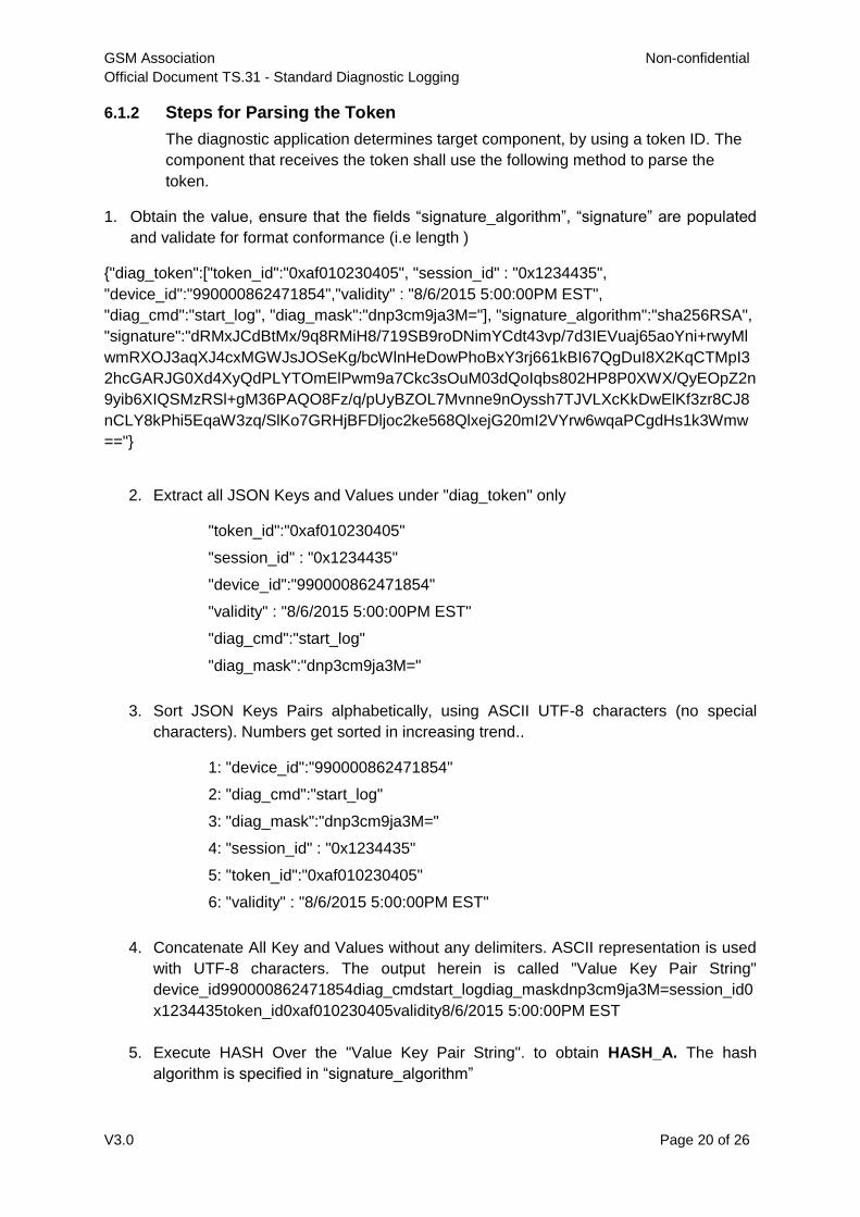
6.1.2 Steps for Parsing the Token
The diagnostic application determines target component, by using a token ID. The
component that receives the token shall use the following method to parse the
token.
1. Obtain the value, ensure that the fields “signature_algorithm”, “signature” are populated
and validate for format conformance (i.e length )
{"diag_token":["token_id":"0xaf010230405", "session_id" : "0x1234435",
"device_id":"990000862471854","validity" : "8/6/2015 5:00:00PM EST",
"diag_cmd":"start_log", "diag_mask":"dnp3cm9ja3M="], "signature_algorithm":"sha256RSA",
"signature":"dRMxJCdBtMx/9q8RMiH8/719SB9roDNimYCdt43vp/7d3IEVuaj65aoYni+rwyMl
wmRXOJ3aqXJ4cxMGWJsJOSeKg/bcWlnHeDowPhoBxY3rj661kBI67QgDuI8X2KqCTMpI3
2hcGARJG0Xd4XyQdPLYTOmElPwm9a7Ckc3sOuM03dQoIqbs802HP8P0XWX/QyEOpZ2n
9yib6XIQSMzRSl+gM36PAQO8Fz/q/pUyBZOL7Mvnne9nOyssh7TJVLXcKkDwElKf3zr8CJ8
nCLY8kPhi5EqaW3zq/SlKo7GRHjBFDljoc2ke568QlxejG20mI2VYrw6wqaPCgdHs1k3Wmw
=="}
2. Extract all JSON Keys and Values under "diag_token" only
"token_id":"0xaf010230405"
"session_id" : "0x1234435"
"device_id":"990000862471854"
"validity" : "8/6/2015 5:00:00PM EST"
"diag_cmd":"start_log"
"diag_mask":"dnp3cm9ja3M="
3. Sort JSON Keys Pairs alphabetically, using ASCII UTF-8 characters (no special
characters). Numbers get sorted in increasing trend..
1: "device_id":"990000862471854"
2: "diag_cmd":"start_log"
3: "diag_mask":"dnp3cm9ja3M="
4: "session_id" : "0x1234435"
5: "token_id":"0xaf010230405"
6: "validity" : "8/6/2015 5:00:00PM EST"
4. Concatenate All Key and Values without any delimiters. ASCII representation is used
with UTF-8 characters. The output herein is called "Value Key Pair String"
device_id990000862471854diag_cmdstart_logdiag_maskdnp3cm9ja3M=session_id0
x1234435token_id0xaf010230405validity8/6/2015 5:00:00PM EST
5. Execute HASH Over the "Value Key Pair String". to obtain HASH_A. The hash
algorithm is specified in “signature_algorithm”
GSM Association Non-confidential
Official Document TS.31 - Standard Diagnostic Logging
V3.0 Page 21 of 26
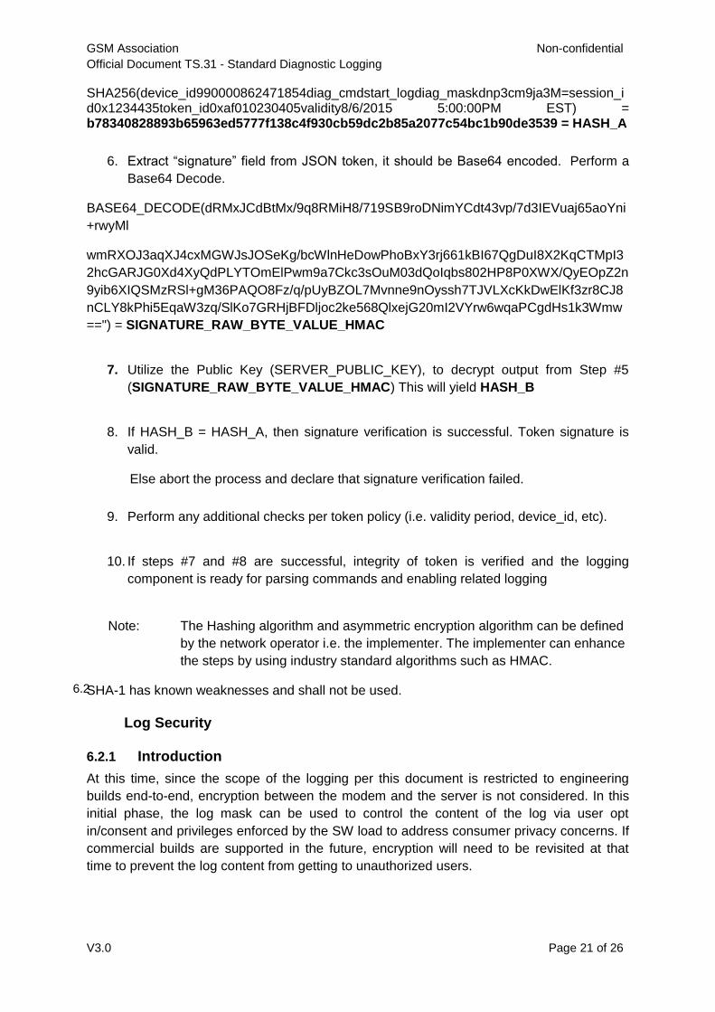
SHA256(device_id990000862471854diag_cmdstart_logdiag_maskdnp3cm9ja3M=session_id0x1234435token_id0xaf010230405validity8/6/2015 5:00:00PM EST) = b78340828893b65963ed5777f138c4f930cb59dc2b85a2077c54bc1b90de3539 = HASH_A
6. Extract “signature” field from JSON token, it should be Base64 encoded. Perform a
Base64 Decode.
BASE64_DECODE(dRMxJCdBtMx/9q8RMiH8/719SB9roDNimYCdt43vp/7d3IEVuaj65aoYni
+rwyMl
wmRXOJ3aqXJ4cxMGWJsJOSeKg/bcWlnHeDowPhoBxY3rj661kBI67QgDuI8X2KqCTMpI3
2hcGARJG0Xd4XyQdPLYTOmElPwm9a7Ckc3sOuM03dQoIqbs802HP8P0XWX/QyEOpZ2n
9yib6XIQSMzRSl+gM36PAQO8Fz/q/pUyBZOL7Mvnne9nOyssh7TJVLXcKkDwElKf3zr8CJ8
nCLY8kPhi5EqaW3zq/SlKo7GRHjBFDljoc2ke568QlxejG20mI2VYrw6wqaPCgdHs1k3Wmw
==") = SIGNATURE_RAW_BYTE_VALUE_HMAC
7. Utilize the Public Key (SERVER_PUBLIC_KEY), to decrypt output from Step #5
(SIGNATURE_RAW_BYTE_VALUE_HMAC) This will yield HASH_B
8. If HASH_B = HASH_A, then signature verification is successful. Token signature is
valid.
Else abort the process and declare that signature verification failed.
9. Perform any additional checks per token policy (i.e. validity period, device_id, etc).
10. If steps #7 and #8 are successful, integrity of token is verified and the logging
component is ready for parsing commands and enabling related logging
Note: The Hashing algorithm and asymmetric encryption algorithm can be defined
by the network operator i.e. the implementer. The implementer can enhance
the steps by using industry standard algorithms such as HMAC.
SHA-1 has known weaknesses and shall not be used.
Log Security
6.2
6.2.1 Introduction
At this time, since the scope of the logging per this document is restricted to engineering
builds end-to-end, encryption between the modem and the server is not considered. In this
initial phase, the log mask can be used to control the content of the log via user opt
in/consent and privileges enforced by the SW load to address consumer privacy concerns. If
commercial builds are supported in the future, encryption will need to be revisited at that
time to prevent the log content from getting to unauthorized users.
GSM Association Non-confidential
Official Document TS.31 - Standard Diagnostic Logging
V3.0 Page 22 of 26
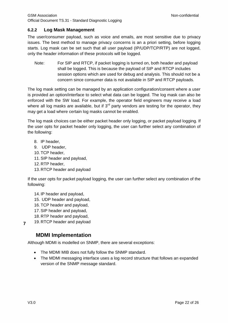
6.2.2 Log Mask Management
The user/consumer payload, such as voice and emails, are most sensitive due to privacy
issues. The best method to manage privacy concerns is an a priori setting, before logging
starts. Log mask can be set such that all user payload (IP/UDP/TCP/RTP) are not logged,
only the header information of these protocols will be logged.
Note: For SIP and RTCP, if packet logging is turned on, both header and payload
shall be logged. This is because the payload of SIP and RTCP includes
session options which are used for debug and analysis. This should not be a
concern since consumer data is not available in SIP and RTCP payloads.
The log mask setting can be managed by an application configuration/consent where a user
is provided an option/interface to select what data can be logged. The log mask can also be
enforced with the SW load. For example, the operator field engineers may receive a load
where all log masks are available, but if 3rd party vendors are testing for the operator, they
may get a load where certain log masks cannot be enabled.
The log mask choices can be either packet header only logging, or packet payload logging. If
the user opts for packet header only logging, the user can further select any combination of
the following:
8. IP header,
9. UDP header,
10. TCP header,
11. SIP header and payload,
12. RTP header,
13. RTCP header and payload
If the user opts for packet payload logging, the user can further select any combination of the
following:
14. IP header and payload,
15. UDP header and payload,
16. TCP header and payload,
17. SIP header and payload,
18. RTP header and payload,
19. RTCP header and payload
MDMI Implementation
7
Although MDMI is modelled on SNMP, there are several exceptions:
The MDMI MIB does not fully follow the SNMP standard.
The MDMI messaging interface uses a log record structure that follows an expanded
version of the SNMP message standard.
GSM Association Non-confidential
Official Document TS.31 - Standard Diagnostic Logging
V3.0 Page 23 of 26
MDMI MIB
7.1
The MDMI OIDs do follow the hierarchical structuring rules defined in SNMP/MIB-2.1
Some MDMI OIDs correspond to data types not allowed in SNMP/MIB-2, although
allowed by ASN.1 syntax. Examples are
Boolean
Special data types – these are objects with multiple values. The objects have an
OID, but the individual values do not.
An example is ServingCellMeasurement (with its own OID), which includes the
variables PCI, RSRP, RSRQ, RSSI, and SINR (none of which have an OID).
Because of these deviations from SNMP/MIB-2, implementations of the MDMI spec should
not be based on the use of standard SNMP tools for generating the structures of the MDMI
OIDs from the MDMI MIB file.
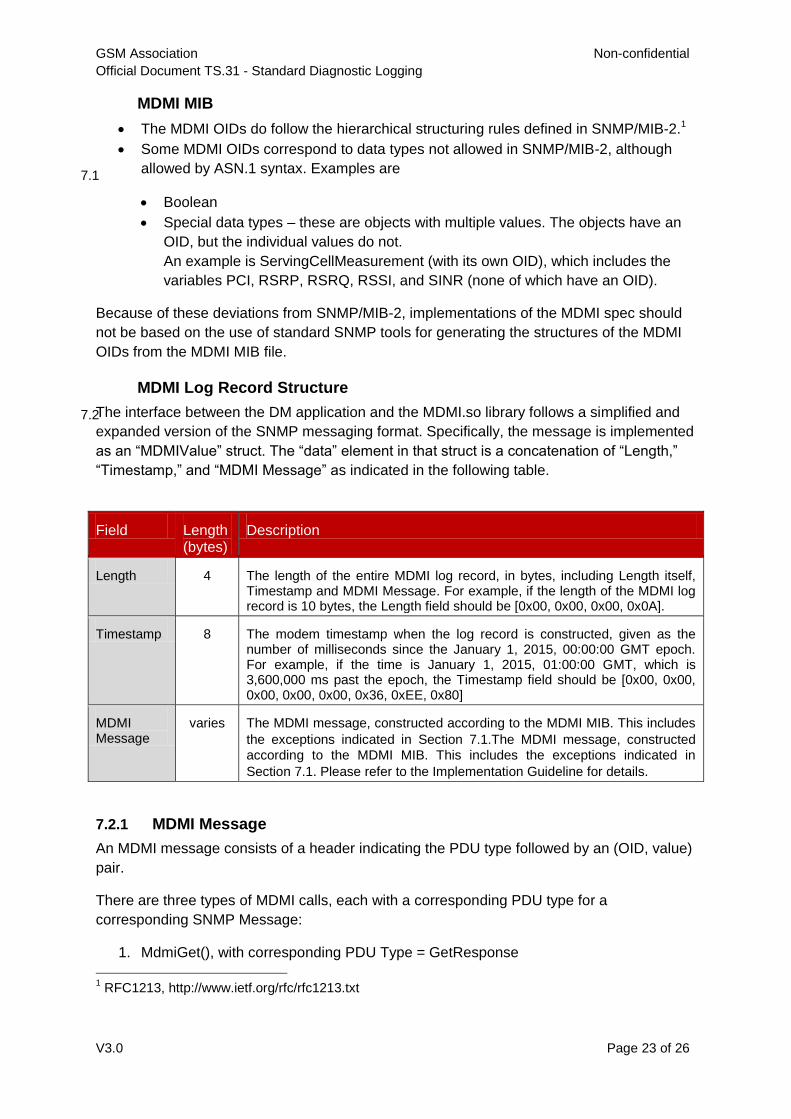
MDMI Log Record Structure
7.2The interface between the DM application and the MDMI.so library follows a simplified and
expanded version of the SNMP messaging format. Specifically, the message is implemented
as an “MDMIValue” struct. The “data” element in that struct is a concatenation of “Length,”
“Timestamp,” and “MDMI Message” as indicated in the following table.
Field Length (bytes)
Description
Length 4 The length of the entire MDMI log record, in bytes, including Length itself, Timestamp and MDMI Message. For example, if the length of the MDMI log record is 10 bytes, the Length field should be [0x00, 0x00, 0x00, 0x0A].
Timestamp 8 The modem timestamp when the log record is constructed, given as the number of milliseconds since the January 1, 2015, 00:00:00 GMT epoch. For example, if the time is January 1, 2015, 01:00:00 GMT, which is 3,600,000 ms past the epoch, the Timestamp field should be [0x00, 0x00, 0x00, 0x00, 0x00, 0x36, 0xEE, 0x80]
MDMI Message
varies The MDMI message, constructed according to the MDMI MIB. This includes
the exceptions indicated in Section 7.1.The MDMI message, constructed
according to the MDMI MIB. This includes the exceptions indicated in
Section 7.1. Please refer to the Implementation Guideline for details.
7.2.1 MDMI Message
An MDMI message consists of a header indicating the PDU type followed by an (OID, value)
pair.
There are three types of MDMI calls, each with a corresponding PDU type for a
corresponding SNMP Message:
1. MdmiGet(), with corresponding PDU Type = GetResponse
1 RFC1213, http://www.ietf.org/rfc/rfc1213.txt
GSM Association Non-confidential
Official Document TS.31 - Standard Diagnostic Logging
V3.0 Page 24 of 26
2. MdmiSubscribe(), with corresponding PDU Type = Trap
3. MdmiInvoke(), with corresponding PDU Type = SetRequest
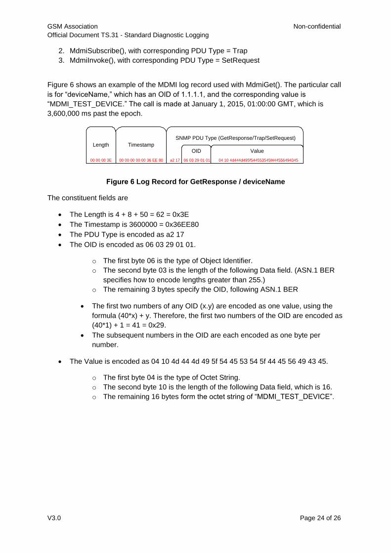
Figure 6 shows an example of the MDMI log record used with MdmiGet(). The particular call
is for “deviceName,” which has an OID of 1.1.1.1, and the corresponding value is
“MDMI_TEST_DEVICE.” The call is made at January 1, 2015, 01:00:00 GMT, which is
3,600,000 ms past the epoch.
04 10 4d444d495f544553545f444556494345
SNMP PDU Type (GetResponse/Trap/SetRequest)
06 03 29 01 01a2 1700 00 00 3E
Length
00 00 00 00 00 36 EE 80
TimestampOID Value
Figure 6 Log Record for GetResponse / deviceName
The constituent fields are
The Length is 4 + 8 + 50 = 62 = 0x3E
The Timestamp is 3600000 = 0x36EE80
The PDU Type is encoded as a2 17
The OID is encoded as 06 03 29 01 01.
o The first byte 06 is the type of Object Identifier.
o The second byte 03 is the length of the following Data field. (ASN.1 BER
specifies how to encode lengths greater than 255.)
o The remaining 3 bytes specify the OID, following ASN.1 BER
The first two numbers of any OID (x.y) are encoded as one value, using the
formula (40*x) + y. Therefore, the first two numbers of the OID are encoded as
(40*1) + 1 = 41 = 0x29.
The subsequent numbers in the OID are each encoded as one byte per
number.
The Value is encoded as 04 10 4d 44 4d 49 5f 54 45 53 54 5f 44 45 56 49 43 45.
o The first byte 04 is the type of Octet String.
o The second byte 10 is the length of the following Data field, which is 16.
o The remaining 16 bytes form the octet string of “MDMI_TEST_DEVICE”.
GSM Association Non-confidential
Official Document TS.31 - Standard Diagnostic Logging
V3.0 Page 25 of 26
Annex A Source Code
Open source code is publicly available for vendors who are complying with the GSMA TSG
standard diagnostic interface standard at GSMA site:
https://github.com/GSMATerminals/TSG-Standard-Diag-Public.
Summary of the files available are listed below.
MDMI.h - header file specifying the MDMI interface.
MDMI-MIB.txt - MIB file specifying log objects to be referenced in MDMI messages.
Mdmi_sample_setgetinvoke.txt - example source code demonstrating MDMI usage
for MdmiGet, MdmiSet, and MdmiInvoke.
README.txt – MDMI Implementation guideline and revision history.
Note: A user account must be created at the following site before access to the
GitHub site.
https://github.com/
GSM Association Non-confidential
Official Document TS.31 - Standard Diagnostic Logging
V3.0 Page 26 of 26
Annex B Document Management
B.1 Document History
Version Date Brief Description of Change Approval
Authority
Editor /
Company
1.0 January
2016
New PRD TS.31 TSG#21
PSMC
Carol Becht /
Verizon
2.0 April 2016 Clarify use of SNMP
Description of MDMI Implementation
and log record structure Add
definition of 'Engineering build'
Add additional clarification and
requirements on security
TSG
Carol Becht /
Verizon
3.0 July 2016 Update architecture to support
multiple diagnostic feeds
Modify JSON token generation
method to specify order of items (to
enable correct HASHing)
TSG
Carol Becht /
Verizon
Other Information
Type Description
Document Owner Terminal Steering Group
Editor / Company Carol Becht / Verizon
It is our intention to provide a quality product for your use. If you find any errors or omissions,
please contact us with your comments. You may notify us at [email protected]
Your comments or suggestions & questions are always welcome.