Embed Size (px)
Citation preview

5’ — 4-3/4”
91
A
A42”19-3/4”
2-11/16”
53”
26-1/2”TA
NG
ENT
2’-0” STANDARDRADIUS
2’ — 6” MINIMUM3’ — 6” MAXIMUM
1’ — 6-1/2”
6-3/16”
1’ — 0” TRAVEL
4’ — 0”HARDWAREPACKAGE
ZIG-ZAG2035 Continuous OverheadPower Chain Conveyor
17
Standard ConveyorSystems Catalog

18
ZIG-ZAG
THE ORIGINAL ENCLOSED TRACKCONVEYORRichards-Wilcox Zig-Zag conveyor is constructed of standard, mod-ular components that guarantee easy installation, modification, andmaintenance. Standard components also guarantee quick accessi-bility through local stocking distributors.
FEATURES: Eleven Standard Components■ Straight Track, 3/16" thick, stocked in 10' lengths■ Welding Jig■ Horizontal Curves, 3/16" thick, 90°, flame hardened■ Top Vertical Curves, 3/16" thick, 90°, flame hardened■ Bottom Vertical Curves, 3/16" thick, 90°, flame hardened■ Conveyor Chain, 6" pitch■ Take-up Assembly■ Inspection Section■ Chain Oiler■ Standard Drive Packages■ Load Pendant Attachments
Vertical Chain Wheels on 6" Centers■ Spread the same amount of load over more wheels■ Reduce the point loading on track and reduce wear
Capacities■ 75 lbs. per load pin■ Standard drive packages up to 750 lb. chain pull
Standard ConveyorSystems Catalog

CONVEYOR CHAIN
2035.01974 CHAINZig-Zag chain is made with heavy steel stampings with a hardenedinner race. Precision alloy balls make Zig-Zag chain rugged anddurable for prolonged dependable life and operation.(Recommended maximum 750 pounds chain pull)
FEATURES6" Pitch Chain
Zig-Zag chain has a pitch of 6" and is the shortest in the industry.This allows up to 33 percent more productivity. The pitch of ourchain allows you to space load pendants closer with less wheel load-ing, allowing for more product throughput. This shorter pitch alsoallows for tighter radius horizontal curves. Richards-Wilcox can pro-vide standard stock 18" radius horizontal curves.
Load Pin
Zig-Zag chain is manufactured with a pendant load pin. Unlike theindustry, Richards-Wilcox pendants are mounted to a load pin andnot the wheel axle. This eliminates unnecessary wear and torsionalloads to critical parts of the chain, thereby increasing your produc-tivity and decreasing your downtime.
Installation and Maintenance
By design, Zig-Zag chain is made for ease of installation and main-tenance. Our chain may be disassembled at any point by simplyremoving a cotter pin. Zig-Zag chain is available from stock in 10'boxes, or in bulk 300' barrels.
19
Standard ConveyorSystems Catalog
1’ – 0” (NOMINAL)
6”
20
STANDARD CURVES
VERTICAL CURVESThe illustration below shows the action of the wheels and the manner in which theybear against the inside of the track when going around vertical curves. The wheels,you will note, contact the top of the track on bottom curves and the bottom of thetrack on top curves. The chain, in this way, is guided around short radius verticalcurves.
HORIZONTAL CURVES The illustration below shows how the chain passes around horizontal curves with-out the use of special guides, sprockets, or wheel turns.
Please note from the cutaway section how the lateral wheels bear on the side of thetrack when the chain is drawn around curves. A series of wheels constantly sharethe load imposed upon the track, thereby reducing friction and insuring smoothconveyor operation.
Curves with these radii are standard:1'-6",2'-0", 2'-3", 3'-0", 3'-3", 4'-0" and 4'-3".
NOTE: All curves up to 3'-0" are available hardened for increased life and made ofheavy-duty 3/16" material, the heaviest in the industry.
Standard ConveyorSystems Catalog
2035.00980 TopVertical Curve
2035.00981 BottomVertical Curve
2035.01352Horizontal Curve
Looking through side of track. Track cut-away of chain passing through reverse verti-cal curve.
Looking through top of track. Track cut-away to give bird’s eye view of chain in track,illustrating operation in horizontal curve.

FIELD FABRICATEDCURVES
21
Standard ConveyorSystems Catalog
30° 45° 60°A B C D B C D B C D
6v" 0'–0" 2'–0" 2'–18" — — — — — —9" 0'–58" 2'–4v" 2'–64" — — — — — —12" 0'–118" 2'–9s" 3'–4" — — — — — —
1'–2" 1'–38" 3'–18" 3'–44" z" 2'–9," 3'–1n" — — —1'–6" 1'–118" 3'–8z" 4'–4" 5b" 3'–1d" 3'–74" — — —1'–9" 2'–58" 4'–14" 4'–64" 9m" 3'–4d" 3'–112" — — —2'–0" 2'–118" 4'–6v" 5'–4" 1'–2z" 3'–7d" 4'–3w" 0'–z" 3'–5b" 4'–24"2'–3" 3'–58" 4'–11s" 5'–64" 1'–6c" 3'–10d" 4'–8" 0'–3v" 3'–7c" 4'–5w"2'–6" 3'–118" 5'–m" 6'–4" 1'–10b" 4'–1d" 5'–4" 0'–6," 3'–9z" 4'–9x"2'–9" 4'–58" 5'–10" 6'–64" 2'–2m" 4'–4d" 5'–108" 0'–10a" 3'–10w" 5'–n"3'–0" 4'–118" 6'–3x" 7'–4" 2'–7z" 4'–7d" 5'–8w" 1'–1d" 4'–2" 5'–48"3'–6" 5'–118" 7'–1s" 8'–4" 3'–32" 5'–1d" 6'–5x" 1'–8m" 4'–3," 5'–11n"4'–0" 6'–118" 8'–0" 9'–4" 4'–z" 5'–7d" 7'–1n" 2'–3n" 4'–7v" 6'–6"4'–6" 7'–118" 8'–10a" 10'–4" 4'–82" 6'–1d" 7'–10m" 2'–s" 4'–10d" 7'–,"5'–0" 8'–118" 9'–8m" 11'–4" 5'–5z" 6'–7d" 8'–6n" 3'–5b" 5'–2a" 7'–7m"5'–6" 9'–118" 10'–7m" 12'–4" 6'–1v" 7'–1d" 9'–38" 4'–2" 5'–5m" 8'–2w"6'–0" 10'–118" 11'–5b" 13'–4" 6'–9," 7'–7d" 9'–11s" 4'–7v" 5'–9c" 8'–9n"6'–6" 11'–118" 12'–3," 14'–4" 7'–6v" 8'–1d" 10'–88" 5'–2a" 6'–w" 9'–4s"7'–0" 12'–118" 13'–2a" 15'–4" 8'–2," 8'–7d" 11'–4s" 5'–9c" 6'–4x" 9'–11b"7'–6" 13'–118" 14'–w" 16'–4" 8'–11w" 9'–1d" 12'–18" 6'–4x" 6'–7n" 10'–62"8'–0" 14'–118" 14'–118" 17'–4" 9'–7d" 9'–7d" 12'–9b" 6'–118" 6'–118" 11'–1a"8'–6" 15'–118" 15'–92" 18'–4" 10'–4w" 10'–1d" 13'–6z" 7'–6z" 7'–2s" 11'–8c"9'–0" 16'–118" 16'–7," 19'–4" 11'–d" 10'–7d" 14'–2b" 8'–1" 7'–6z" 12'–34"9'–6" 17'–118" 17'–6c" 20'–4" 11'–9c" 11'–1d" 14'–1z" 8'–7," 7'–92" 12'–10x"10'–0" 18'–118" 18'–4n" 21'–4" 12'–5m" 11'–7d" 15'–72" 9'–2d" 8'–1" 13'–58"10'–6" 19'–118" 19'–38" 22'–4" 13'–2c" 12'–1d" 16'–4" 9'–9w" 8'–4v" 14'–z"11'–0" 20'–118" 20'–12" 23'–4" 13'–10m" 12'–7d" 17'–2" 10'–4n" 8'–7," 14'–7"11'–6" 21'–118" 20'–11d" 24'–4" 14'–74" 13'–1d" 17'–9" 10'–11s" 8'–11a" 15'–1d"12'–0" 22'–118" 21'–104" 25'–4" 15'–3w" 13'–7d" 18'–5v" 11'–6b" 9'–2d" 15'–8m"12'–6" 23'–118" 22'–8n" 26'–4" 16'–4" 14'–1d" 19'–1," 12'–1a" 9'–6c" 16'–3w"
VERTICAL CURVE DATA
Note: The Vertical Curve dimensions in the chartbelow are based on using 2'–0" radius curves.
45°, 2'–0" radius vertical curve shown.

22
TAKE-UPASSEMBLIES
2035.01687 FRAMEDTAKE-UPFactory made, ready to be hoisted and hung, this frameprovides a rigid base and helps make alignment positive.The frame is permanently mounted; only the actuator andconveyor move. Tensioning is accomplished with yourchoice of screw, spring, or air cylinder packages listedbelow. Available for 2'-0" R curves (4' maximum trackspread).
Some type of tensioning is necessary on all Zig-Zag con-veyor systems to take up slack chain created by wear ortemperature changes. In addition to the factory made ver-sions described on this page, Richards-Wilcox makes screwtake-up fittings for field assembly.
Note: Complete unit consists of one frame and one set ofhardware for screw, spring or air take-up.
FRAMED TAKE-UPACTUATOR PACKAGESCatalog No. Description2035.01700 Air Take-Up Package2035.02685 Screw Take-Up Package2035.02686 Spring Take-Up Package
Standard ConveyorSystems Catalog
5/16” WASHER
BEARING
3/8 x 1-1/2 HEXMACH. BOLT
5’ — 4-3/4”
9/16” HOLE FOR 1/2” DROP ROD
A
A42”19-3/4”
2-11/16”
53”
26-1/2”
TAN
GEN
T
2’-0” STANDARDRADIUS
2’ — 6” MINIMUM3’ — 6” MAXIMUM
1’ — 6-1/2”
6-3/16”
1’ — 0” TRAVEL
4’ — 0”HARDWAREPACKAGE
Framed Take-up
2035.02686 Spring Package
FramedTake-Up
MoveableMember
Framed take up
2035.02685 Screw Package
FramedTake-Up
MoveableMember
2035.01700 Air Package
FramedTake-Up
MoveableMember

90° T
RACK CURVE
90° TRACK CURVE
ADD STRAIGHT TRACKBETWEEN CURVES AS
SYSTEM LAYOUT REQUIRES
DIRECTION OF TRAVEL
2' - 7" MIN.4' - 1" MAX. (Screw)
3'-7" MAX. (Air)
2’ - 0”3”
1-1/4”
1/2” SUPPORTRODS IF NECESSARY
6-1/2”
21-1/2”
#2035 TRACK
CHAINTRAVEL
3'-0" MIN.14'-0" MAX.
TAKE-UP FITTINGS ANDEXPANSION SLEEVE
2035.00583 SCREWTAKE-UP FITTINGS(1’-6” Travel)2035.02497 AIRTAKE-UPFITTINGS (1’-0” Travel)
NOTE: Curves are not included in assembly.
23
Standard ConveyorSystems Catalog
2035.01114EXPANSION SLEEVEExpansion sleeves are used mainly in bakeovens and are located in each track in the areaof the oven expansion joint. This allows bothoven and conveyor to expand and contract inunison. Many ovens, depending on lengthand temperature, do not have expansionjoints. In such cases, it is often advisable to usean expansion sleeve at the exit and entrancetracks to prevent snaking or waviness in thetrack both inside and outside the oven.
Relative to installation, the movable track inthe sleeve should be moved out 2" from thecompressed length which would then be anoverall of 1'-6" instead of 1'-4" as shown. Thisallows for both contraction and expansion inthe track.
1’ — 4” MIN.1’ — 10” MAX.
2”
2” MIN.8” MAX.
10”6”
TRAVEL
2035.00583

24
DRIVE UNITS
The drive units are fabricated using a skeleton drive unit. The motorand reducer are connected with sprockets and roller chain to thehead shaft, which drive the caterpillar chain and transmit the powerto the conveyor chain. Adequate protection is provided for reason-able momentary overloads, and the assembly is also equipped with afriction clutch for protection against excessive overload.
The 2035.01371 drive uses a 3/4 horsepower inverter duty motorand a speed reducer with a 50 to 1 ratio. The drive has a constantspeed of 16 feet per minute at 60 hertz, or by using the 2035.02798(230V) or 2035.02800 (460V) A.C. inverter, has a speed range of 3to 16 FPM.
The 2035.01372 drive uses a 1 1/2 horsepower inverter duty motorand a speed reducer with a 20 to 1 ratio. The drive has a constantspeed of 45 feet per minute at 60 hertz, or by using the 2035.02799(230V) or 2035.02802 (460V) A.C. inverter, has a speed range of 9to 45 FPM.
These drives are used in Zig-Zag Power Chain Conveyors, Twin-Trakand OveR-Way Power & Free Conveyor Systems.
The capacity is 750 lbs. chain pull.
NOTE: The chain covers are supplied in Safety Yellow.
Standard ConveyorSystems Catalog
Drive Unit (shown with Chain Guards)
Drive Unit (shown without Chain Guards)
131/2"
1'–6"
6'–0"
Conveyor Travel

SKELETON DRIVE
25
Standard ConveyorSystems Catalog
The 2035.01373 skeleton drive unit incorporates the use of a cater-pillar drive chain connection to the head shaft and idler shaft assem-bly. The skeleton drive is not equipped with a motor, reducer, frictionclutch, driven sprocket, or roller chain.
The skeleton drive unit is used in Zig-Zag, Twin-Trak and OveR-Wayapplications. Most commonly, the unit is used where the customerneeds to replace their existing drive, but wants to use the existingmotor, reducer, and sprockets. The skeleton is also used where thecustomer wants to supply his own motor, reducer, and sprockets. Theunit can be used with an extended head shaft and jackshaft to jointwo or more conveyors together for timing purposes.
The capacity of the unit is 750 lbs. Chain Pull.
2035.01373 (shown with Chain Guards)
2035.01373 (shown without Chain Guards)
RW RWWARNING
131/2"
6'–0"
117/8"
3'–9"
Conveyor Travel

26
The proper lubrication of the conveyor chain is of paramount importance notonly to the successful operation of a conveyor system, but to the life of theproduct as well. Proper lubricant should be recommended by a qualified lubri-cating engineer who has made a study of the processing machinery andatmospheric conditions to which the system will be subjected. Special safe-guards must be taken to protect the chain when it moves through high tem-peratures, extremely low temperatures, acid conditions such as bonderizing,alkaline washers, or other chemicals which could reduce the life of the bear-ings and other parts. We caution against the use of graphite based lubricantswhich tend to build up excessive deposits of foreign matter unless the chain isthoroughly cleaned at regular intervals. We urge the use of our sanitary hookin acid or paint spray conditions.
2035.02724 Automatic TimerControlled LubricatorThis automatic timer controlled lubricator is designed to precisely lubricate thecritical bearing points of the conveyor chain. It has five nozzles, located to dis-pense lubricant on the vertical and lateral wheel bearings, vertical link pin androller. Each nozzle has its own adjustable valve to control the amount of lubri-cant that is dispensed. It is equipped with a 168 hour adjustable timer whichcan be set for as little as 20 minutes out of 168 hours of conveyor operation.
2035.00669 Electro-Brush OilerThe illustration shows the brush type oiling device. The brush makes contactwith the chain, distributing the lubricant to the various parts. A 115 volt sole-noid shut-off valve is provided at the bottom of the tank reservoir.
2035.00664 Brush Oiler (Not Shown)The brush oiler applies lubrication to the chain by gravity feed. The brushmakes contact with the chain, distributing the lubricant to the various parts.A toggle shut off at the top of the reservoir is provided. NOTE: We do not rec-ommend this oiler in finishing systems.
2035.00820 Inspection Track SectionThe inspection track section, formed out of this 3/16" track, facilitates inspec-tion and maintenance at points other than the drive unit. It may be placed inany run of straight track. This section is made with the top and sides opendown to the center of the chain. This allows for full inspection of the chain forproper lubrication, chain tension, and general condition of the conveyorchain. The opening is covered by a removable housing and is equipped witha handle. The inspection section also permits easy installation and removal ofchain. The most desirable location is at the lowest point between the outputof the drive unit and the take-up unit. The inspection section is furnished in astandard finish to match the rest of the system.
The inspection section is used in all Zig-Zag, Twin-Trak, and OveR-Way sys-tems. In certain applications, such as a large system, it may be desirable to useseveral inspection sections.
Standard ConveyorSystems Catalog
2035.02724 Automatic TimerControlled Lubricator
2035.00669 Electro-Brush Oiler
2035.00820 Inspection Section
LUBRICATION ANDINSPECTION SECTION

2035 STANDARDLOAD PENDANTS
27
Standard ConveyorSystems Catalog
We have developed a series of standardload carrying devices designed to coverthe essential requirements for connect-ing the load to the conveyor chain.
Since the ultimate device required tocarry the load on the conveyor must bespecially designed to fit the articlewhich is being handled, it is almostimpossible to illustrate a load pendantfor every problem. It is also desirablein many cases to experiment with vari-ous types of load carriers before findingthe one most satisfactory for the job.
The standard load pendants shown on this and following pages are carried instock for immediate shipment.
Almost any type of load suspension fitting can be attached to the2035.00319 clevis pendant.
2035.00319 Standard Clevis LoadPendants, Capacity 75 lbs.
BOTTOMOF TRACK
1” 3/8”
21/64”
RIVET(FACTORY)3-1/4”
Part 2035.00318Straight Side Pendant
The Straight Side Pendant is similar tothe Standard Clevis Pendant exceptthe pendant sides are straight. It usesa scissor-like action to attach directlyto the load pin on the vertical link ofthe conveyor chain.
The pendant may be spaced on multi-ples of 6". The pendant is furnished ina zinc-plated finish. This type of pen-dant is used where it is permitted tohave swinging loads. The pendant isallowed to pivot, as the conveyormakes elevation changes.
BOTTOMOF TRACK
3-3/8”
1”
21/64”
1/4”
RIVET(FACTORY)
Part 2035.00316Rigid Clevis Pendant
The Rigid Clevis Pendant is designedto be used where a swinging load maybe objectionable. This pendant is sim-ilar to the Rigid Straight Side Pendantexcept there is an offset in the pen-dant sides to allow for a 1/4" gap.
The pendant may be spaced on multi-ples of 6". The pendant is furnished ina zinc-plated finish. This pendantalways remains perpendicular to thetrack. The pendant can be attached toa load bar or directly to a productrack.
RIVET(FACTORY)
BOTTOMOF TRACK
3-3/8”
1” 3/8”
21/64”
Part 2035.00317Rigid Straight Side Pendant
The Rigid Straight Side Pendant is sim-ilar to the Rigid Clevis Pendant exceptthe sides are straight. It may bespaced on multiples of 6". It attachesdirectly to the load pin on the verticallink of the conveyor chain and is fur-nished in a zinc-plated finish.
This pendant may be used where aswinging load may be objectionableor not permitted. The pendant alwaysremains perpendicular to the track.
BOTTOMOF TRACK
3-3/8”
1”
21/64”
1/4”
RIVET(FACTORY)
5/8”
28
2035 STANDARDLOAD PENDANTS
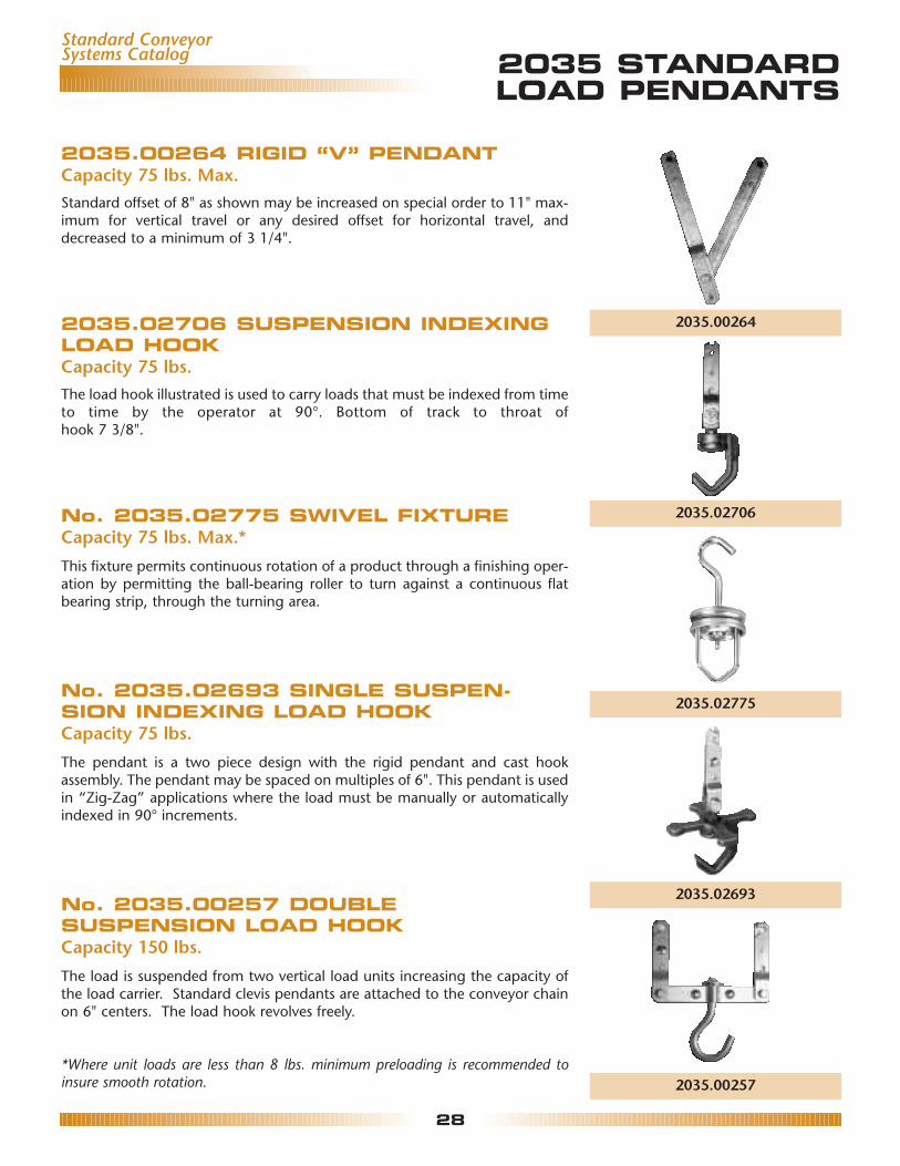
2035.00264 RIGID “V” PENDANTCapacity 75 lbs. Max.Standard offset of 8" as shown may be increased on special order to 11" max-imum for vertical travel or any desired offset for horizontal travel, anddecreased to a minimum of 3 1/4".
2035.02706 SUSPENSION INDEXINGLOAD HOOKCapacity 75 lbs.The load hook illustrated is used to carry loads that must be indexed from timeto time by the operator at 90°. Bottom of track to throat ofhook 7 3/8".
No. 2035.02775 SWIVEL FIXTURECapacity 75 lbs. Max.*This fixture permits continuous rotation of a product through a finishing oper-ation by permitting the ball-bearing roller to turn against a continuous flatbearing strip, through the turning area.
No. 2035.02693 SINGLE SUSPEN-SION INDEXING LOAD HOOKCapacity 75 lbs.The pendant is a two piece design with the rigid pendant and cast hookassembly. The pendant may be spaced on multiples of 6". This pendant is usedin “Zig-Zag” applications where the load must be manually or automaticallyindexed in 90° increments.
No. 2035.00257 DOUBLESUSPENSION LOAD HOOKCapacity 150 lbs.The load is suspended from two vertical load units increasing the capacity ofthe load carrier. Standard clevis pendants are attached to the conveyor chainon 6" centers. The load hook revolves freely.
*Where unit loads are less than 8 lbs. minimum preloading is recommended toinsure smooth rotation.
Standard ConveyorSystems Catalog
2035.00264
2035.02706
2035.02775
2035.02693
2035.00257

2035 STANDARDLOAD PENDANTS
29
Standard ConveyorSystems Catalog
2035.02772 DOUBLE SUSPENSIONLOAD BAR ASSEMBLYCapacity 150 lbs. per assemblyBy suspending the load from two points on the chain, the load carryingcapacity is increased. This pendant can be attached to the conveyor chain ona minimum of 12" centers. The basic load bar assembly provides a means ofattaching a product hook or clevis directly to the center hole.
2035.02702 DOUBLE SUSPENSIONLOAD HOOK ASSEMBLYCapacity 150 lbs. per assemblyBy suspending the load from two points on the chain, the load carryingcapacity is increased. This pendant can be attached to the conveyor chain ona minimum of 12" centers. The Load Hook assembly is used for finishingapplications where the load must be manually indexed in 90° increments.
2035.02699 DOUBLE SUSPENSIONROTATING STAR INDEXING PENDANTCapacity 150 lbs. for manual indexingDistance from bottom of track to throat of hook is 8 7/8". This pendant canbe used to manually index or automatically index the part. This pendant canbe used with a Rotating Cam or Continuous Rotating Cam, permitting auto-matic rotation and indexing in increments of 90°. The pendants and load barhave a zinc plated finish while the hook assembly is finished inRichards-Wilcox Gloss-Tek powder coat. This pendant is most commonly usedfor finishing applications where it is necessary to rotate the part. This pendantassembly can be spaced on 6" increments with a minimum of 12" centers.
2035.00430 MULTIPLE SUSPENSIONLOAD HOOKCapacity 300 lbs.By suspending the load from four points on the chain, the load carryingcapacity is increased again. Standard clevis pendants are attached at fourpoints to each vertical link pendant, and the load bar is free to swivel so thatthere will be no binding action when going around curves. Bottom of trackto throat of hook is 9 1/16".
2035.02772
2035.02702
2035.02699
2035.00430

30
ORGANIZER LOOP
The Organizer Loop is a gravity loop conveyor consisting of standard Richards-Wilcox materials. Ideal for any assembly application.
Standard ConveyorSystems Catalog
P804
1’-4”2’-0”
AB 9”9”
2’-0”
P1168
P820
P316
P1167 P11672035.01167 2035.01168
2035.00804 2035.00820
2035.01167
2035.00316
2035.00804 2035.00155 2035.00820 2035.01167 2035.01168 2035.01974 CHAINQUANTITY ORDER WELDING INSPECTION QUANTITY ORDER
A DIM. B DIM. REQUIRED QUANTITY JIG SECTION CURVE TAKEUPS REQUIRED QUANTITY
8' - 0" 6' - 6" 10 ft. (10 ft.) (1) 1 2 2 18 ft. (20 ft.)10' - 0" 8' - 6" 14 ft. (20 ft.) (1) 1 2 2 22 ft. (30 ft.)12' - 0" 10' - 6" 18 ft. (20 ft.) (1) 1 2 2 26 ft. (30 ft.)14' - 0" 12' - 6" 22 ft. (30 ft.) (1) 1 2 2 30 ft. (30 ft.)16' - 0" 14' - 6" 26 ft. (30 ft.) (1) 1 2 2 34 ft. (40 ft.)18' - 0" 16' - 6" 30 ft. (30 ft.) (1) 1 2 2 38 ft. (40 ft.)20' - 0" 18' - 6" 40 ft. (40 ft.) (1) 1 2 2 42 ft. (50 ft.)24' - 0" 22' - 6" 42 ft. (50 ft.) (1) 1 2 2 50 ft. (50 ft.)30' - 0" 28' - 6" 54 ft. (60 ft.) (1) 1 2 2 62 ft. (70 ft.)35' - 0" 33' - 6" 64 ft. (70 ft.) (1) 1 2 2 72 ft. (80 ft.)40' - 0" 38' - 6" 74 ft. (80 ft.) (1) 1 2 2 82 ft. (90 ft.)
NOTE 1: It will be necessary to add the cost of the 2035.00316 rigid pendants when using Richards-Wilcox2035.01974 Chain.
NOTE 2: When using the 2035.01096 chain, remember the pendants are an integral part of the chain and arespaced at 8" centers.

SUGGESTEDSUSPENSION METHODS
31
Standard ConveyorSystems Catalog
WELDED Where the building trusses are too far apart for the 10'-0" hanger supports, it is necessary to install headers or super-structure. Since conditions vary greatly from job to job, the header steel must be designed and installed to accommo-date the conveyor and the building.

32
Standard ConveyorSystems Catalog SUGGESTED
SUSPENSION METHODS
THREADED ROD
Connection to Lower Chord of Building Truss or Joistwith Rod Type Hangers
Connection to Channel Header with Rod TypeHangers
Connection to 2035 Track Using Welded Bracket andRod Type Hanger
Connection to 2035 Track Using 2035.01912 Bracket

TYPICAL LAYOUT
33
Standard ConveyorSystems Catalog
NO. 2035 ZIG-ZAG CONVEYORS
11" -
2"
10" -
0"
BILL OF MATERIALQUANTITY ITEM NUMBER DESCRIPTION
3 2035.00155 Welding Jig235 2035.02775 Swivel Fixture37 2035.00471 Track (3/16") 10' length
1 2035.00820 Inspection Section3 2035.00980 Top Vertical Curve 2'-0" Radius x 90 Degrees3 2035.00981 Bottom Vertical Curve 2'-0" Radius x 90 Degrees
10 2035.01352 Horizontal Curve 2'-0" Radius x 90 Degrees1 2035.01371 Drive Unit 3-16 FPM1 2035.01687 Framed Take-up Package1 2035.01700 Air Take-up Package
47 2035.01974 Conveyor Chain 10' Lg. Cotter2 2035.02012 Traction Wheel 24" Dia.2 2035.02064 Horizontal Curve 1'-6" Radius x 90 Hardened1 2035.02724 Chain Lubricator with Timer1 2035.02800 A.C. Inverter 3/4 H.P. 208/230V 3Phase


![Cold atoms in zig-zag optical lattices [0.7cm] …€¦ · zig-zag lattices: realize Haldane insulator phase without polar interactions 13/18. RTG seminar - Cold atoms in zig-zag](https://img.pdfslide.us/doc/110x75/5fb646d00fb65e0f2d10f8e1/cold-atoms-in-zig-zag-optical-lattices-07cm-zig-zag-lattices-realize-haldane.jpg)