Embed Size (px)
Citation preview
publishe
din
Opt
.Com
mun
.282,26
34-2
641
(200
9),do
i:10
.101
6/j.op
tcom
.200
9.03
.046
Standard and non-standard metarefractionwith confocal lenslet arrays
Johannes Courtial
Department of Physics & Astronomy, Faculty of Physical Sciences, University ofGlasgow, Glasgow G12 8QQ, UK
Abstract
A recent paper demonstrated that two lenslet arrays with focal lengths f1 and f2,separated by f1 + f2, change the direction of transmitted light rays approximatelylike the interface between isotropic media with refractive indices n1 and n2, wheren1/n2 = !f1/f2 [J. Courtial, New J. Phys. 10, 083033 (2008)]. This is true if lightpasses through corresponding lenslets, that is lenslets that share an optical axis.Light can also pass through di!erent combinations of non-corresponding lenslets.Such light can be either absorbed or allowed to form “ghost images”; either way, itleads to a limitation of the field of view of confocal lenslet arrays. This paper de-scribes, qualitatively and quantitatively, a number of such field-of-view limitations.
Key words: confocal lenslet arrays, METATOYs, field of view, geometrical optics,optical materialsPACS: 42.15.-i
1 Introduction
A recent paper [1] introduced the idea of using a sheet comprising two lenslet(or microlens) arrays to mimic refraction. The two lenslet arrays have to sharethe same focal plane: they are confocal. The basis of this idea is that the equa-tions describing the light-ray-direction change due to confocal lenslet arrays(CLAs) and refraction due to refractive-index interfaces are very similar: inthe former, the angles !1 and !2 with which a light ray respectively entersand exits a CLA sheet (Fig. 1) are related through the equation
tan !1 = " tan !2, (1)
Email address: [email protected] (Johannes Courtial).
Preprint submitted to Elsevier 18 May 2009
where
" = !f2
f1(2)
is minus the ratio of the focal lengths of the two lenslet arrays [1]; in the latter,the angle of incidence in a medium with refractive index n1, !1, and the angleof refraction in a medium with refractive index n2, !2, are related throughSnell’s law,
sin !1 =n2
n1sin !2. (3)
For small angles, when sin !1,2 " tan !1,2, the equation describing the light-ray-direction change due to CLAs (Eq. (1)) is the same as Snell’s law, whereby
" =n2
n1. (4)
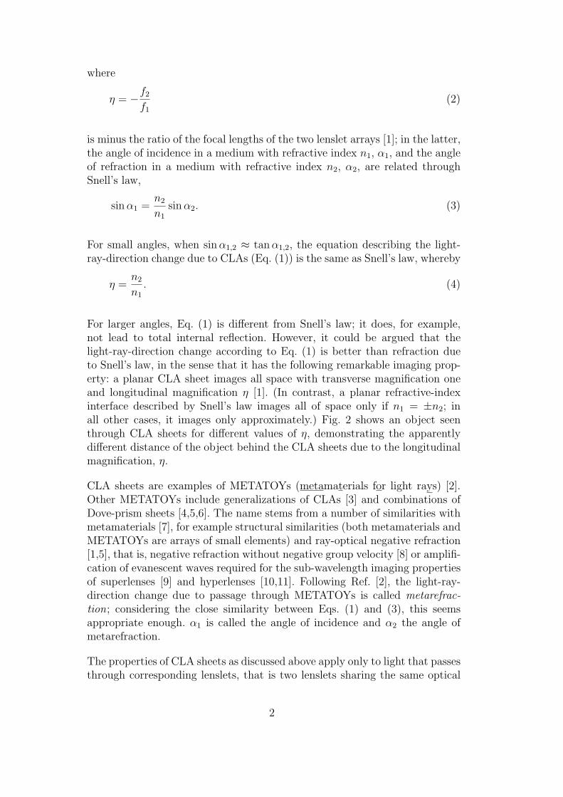
For larger angles, Eq. (1) is di!erent from Snell’s law; it does, for example,not lead to total internal reflection. However, it could be argued that thelight-ray-direction change according to Eq. (1) is better than refraction dueto Snell’s law, in the sense that it has the following remarkable imaging prop-erty: a planar CLA sheet images all space with transverse magnification oneand longitudinal magnification " [1]. (In contrast, a planar refractive-indexinterface described by Snell’s law images all of space only if n1 = ±n2; inall other cases, it images only approximately.) Fig. 2 shows an object seenthrough CLA sheets for di!erent values of ", demonstrating the apparentlydi!erent distance of the object behind the CLA sheets due to the longitudinalmagnification, ".
CLA sheets are examples of METATOYs (metamaterials for light rays) [2].Other METATOYs include generalizations of CLAs [3] and combinations ofDove-prism sheets [4,5,6]. The name stems from a number of similarities withmetamaterials [7], for example structural similarities (both metamaterials andMETATOYs are arrays of small elements) and ray-optical negative refraction[1,5], that is, negative refraction without negative group velocity [8] or amplifi-cation of evanescent waves required for the sub-wavelength imaging propertiesof superlenses [9] and hyperlenses [10,11]. Following Ref. [2], the light-ray-direction change due to passage through METATOYs is called metarefrac-tion; considering the close similarity between Eqs. (1) and (3), this seemsappropriate enough. !1 is called the angle of incidence and !2 the angle ofmetarefraction.
The properties of CLA sheets as discussed above apply only to light that passesthrough corresponding lenslets, that is two lenslets sharing the same optical
2
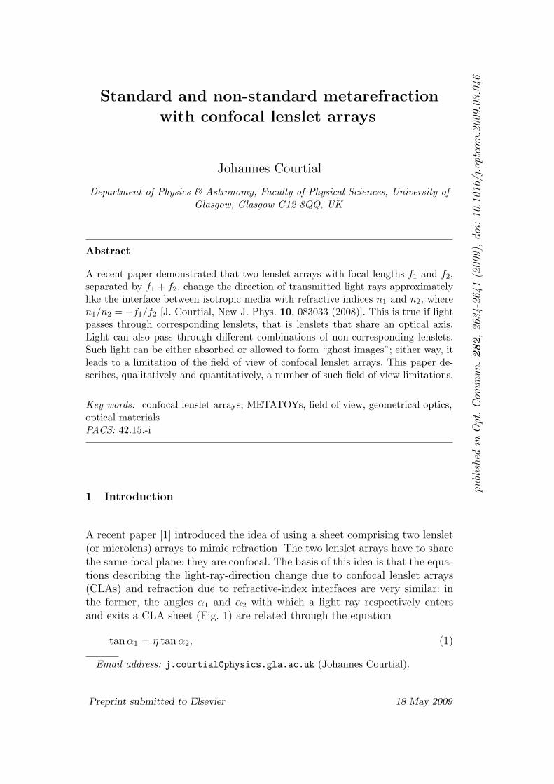
Fig. 1. Light rays passing through confocal-lenslet-array (CLA) sheets. (a) The CLAsheet is in the xy plane; the figure shows a yz projection. (b) A lenslet in the first(left) array focusses all incident light rays with angle of incidence !1 to a point in thefocal plane F . Of those rays, those that pass through the corresponding lenslet in thesecond (right) array (that is, the lenslet in the second array with the same opticalaxis) leave it with an angle of metarefraction !2, where f1 tan!1 = !f2 tan!2. Thefocal lengths of the lenslets in the first and second array are f1 and f2, respectively.Optional absorbers (thick black horizontal lines) can remove light rays that wouldotherwise pass through a non-corresponding lenslet in the second array. (Adaptedfrom Ref. [1].)
axis (like the ones in Fig. 1(b)). Here this is called standard metarefraction.Light that enters through one lenslet and exits through a lenslet other thanthe corresponding lenslet is re-directed di!erently. This is called non-standardmetarefraction.
The possibility of non-standard metarefraction was already noticed in Ref.[1], and in all the simulations in Ref. [1] light that would otherwise haveundergone non-standard metarefraction was filtered out with appropriatelyplaced absorbers, leading to a darkening of part of the view (see Fig. 2). Ifsuch light is not filtered out, it leads to “ghost images”: additional images anobject seen through a CLA sheet (Fig. 3).
The work on CLA sheets is closely related to “integral” photography, a methodfor taking (and viewing) three-dimensional (3D) photos [13]. In integral pho-tography, the second lenslet array views a photo of the intensity distributioncreated by the first lenslet array, instead of viewing it directly, as in the caseof CLA sheets. Integral photography can also be seen as the basis of lentic-ular printing, the technique used to create pictures (for example postcards)that provide two or more di!erent images when seen from di!erent angles, oreven 3D views [14]. It is also the basis of many 3D displays [15,16]. A setupthat is essentially the same as the camera in integral photography can alsobe used in a completely di!erent way: instead of aiming for 3D imaging, such“multiaperture imaging” [17] is used in combination with digital processing ofthe image obtained in the focal plane and concentrates on the small apertureof the individual lenses, which can include faster optics and lower aberrations[18]. The digital processing can also lead to superresolution [19]. In these con-texts, the field of view of lenslet arrays has been researched; a good review
3
=2 =4
=-1
=-0.5 =+0.5
=-2
=1
Fig. 2. Chess piece seen through CLA sheets with di!erent focal-length ratios" = !f2/f1 and, for comparison, seen directly (inset labelled " = 1). The chesspiece is in the same position in all frames, but the longitudinal imaging propertiesof each sheet make the chess piece’s distance behind the sheet appear stretchedby a factor ". The brightness of the view is clearly di!erent for di!erent valuesof ". In a few frames, most notably those corresponding to " = !2, " = !1 and" = 4, the brightness even changes across the view. The reduction in brightness isdue to light that would have undergone non-standard metarefraction being filteredout by absorbers (see Fig. 1(b)). The frames in this figure are detailed ray-tracingsimulations through the structure of CLA sheets, each comprising 2 # 200 # 200lenslets, created using the freely-available software POV-ray [12]. The geometry ofthe lenslet arrays is described in more detail in Ref. [1]. A movie (MPEG-4, 396KB) of the view through CLA sheets with the value of " changing can be found inthe supporting online material. (Adapted from Ref. [1].)
of methods to deal with “parasitic images” (the equivalent of what is calledhere “ghost images”) and corrections to other lens aberrations can be foundin Ref. [20].
The CLAs discussed here, in which the focal lengths of the two lenslet arraysare di!erent [1], are a generalization of basic CLAs in which both lensletarrays have the same focal length. The latter have been used in pseudoscopic(depth-inverting) imaging systems [21,22,23] (in the case of Ref. [23] in theform of arrays of graded-index lenses). Applications include correcting thepseudoscopic images provided by integral photography [22].
This paper is aimed at providing a more detailed analysis of the conditions un-der which standard and non-standard metarefraction occur in CLAs in whichthe lenslet arrays have di!erent focal lengths, and how non-standard metare-
4
(a) (b)
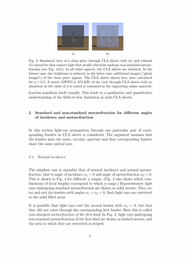
Fig. 3. Simulated view of a chess piece through CLA sheets with (a) and without(b) absorbers that remove light that would otherwise undergo non-standard metare-fraction (see Fig. 1(b)). In all other aspects, the CLA sheets are identical. In theformer case, the brightness is reduced; in the latter case, additional images (“ghostimages”) of the chess piece appear. The CLA sheets shown here were calculatedfor " = 0.5. A movie (MPEG-4, 372 KB) of the view through CLA sheets with noabsorbers as the value of " is varied is contained in the supporting online material.
fraction manifests itself visually. This leads to a qualitative and quantitativeunderstanding of the field-of-view limitation in such CLA sheets.
2 Standard and non-standard metarefraction for di!erent anglesof incidence and metarefraction
In this section light-ray propagation through one particular pair of corre-sponding lenslets in CLA sheets is considered. The argument assumes thatthe lenslets have the same, circular, aperture and that corresponding lensletsshare the same optical axis.
2.1 Normal incidence
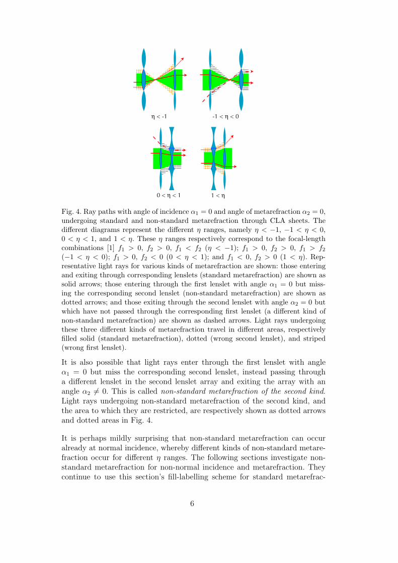
The simplest case is arguably that of normal incidence and normal metare-fraction, that is angle of incidence !1 = 0 and angle of metarefraction !2 = 0.This is shown in Fig. 4 for di!erent " ranges. (Fig. 4 also shows which com-binations of focal lengths correspond to which " range.) Representative lightrays undergoing standard metarefraction are shown as solid arrows. They en-ter and exit the lenslets with angles !1 = !2 = 0. Such light rays are restrictedto the solid filled areas.
It is possible that light rays exit the second lenslet with !2 = 0, but thatthey did not enter through the corresponding first lenslet. Here this is callednon-standard metarefraction of the first kind. In Fig. 4, light rays undergoingnon-standard metarefraction of the first kind are drawn as dashed arrows, andthe area to which they are restricted is striped.
5
1 < 0 < < 1
< -1 -1 < < 0
Fig. 4. Ray paths with angle of incidence !1 = 0 and angle of metarefraction !2 = 0,undergoing standard and non-standard metarefraction through CLA sheets. Thedi!erent diagrams represent the di!erent " ranges, namely " < !1, !1 < " < 0,0 < " < 1, and 1 < ". These " ranges respectively correspond to the focal-lengthcombinations [1] f1 > 0, f2 > 0, f1 < f2 (" < !1); f1 > 0, f2 > 0, f1 > f2
(!1 < " < 0); f1 > 0, f2 < 0 (0 < " < 1); and f1 < 0, f2 > 0 (1 < "). Rep-resentative light rays for various kinds of metarefraction are shown: those enteringand exiting through corresponding lenslets (standard metarefraction) are shown assolid arrows; those entering through the first lenslet with angle !1 = 0 but miss-ing the corresponding second lenslet (non-standard metarefraction) are shown asdotted arrows; and those exiting through the second lenslet with angle !2 = 0 butwhich have not passed through the corresponding first lenslet (a di!erent kind ofnon-standard metarefraction) are shown as dashed arrows. Light rays undergoingthese three di!erent kinds of metarefraction travel in di!erent areas, respectivelyfilled solid (standard metarefraction), dotted (wrong second lenslet), and striped(wrong first lenslet).
It is also possible that light rays enter through the first lenslet with angle!1 = 0 but miss the corresponding second lenslet, instead passing througha di!erent lenslet in the second lenslet array and exiting the array with anangle !2 $= 0. This is called non-standard metarefraction of the second kind.Light rays undergoing non-standard metarefraction of the second kind, andthe area to which they are restricted, are respectively shown as dotted arrowsand dotted areas in Fig. 4.
It is perhaps mildly surprising that non-standard metarefraction can occuralready at normal incidence, whereby di!erent kinds of non-standard metare-fraction occur for di!erent " ranges. The following sections investigate non-standard metarefraction for non-normal incidence and metarefraction. Theycontinue to use this section’s fill-labelling scheme for standard metarefrac-
6
tion (solid) and non-standard metarefraction of the first (striped) and second(dotted) kind.
2.2 Onset of non-standard metarefraction of the first kind: the first criticalangles
Consider looking through a CLA sheet. What you see in a specific directionis determined by the history of the light rays arriving at the eye from thatdirection. When traced backwards from the eye (which is what ray-tracingsoftware, such as POV-Ray [12], does), light rays undergoing non-standardmetarefraction of the first kind pass through a second lenslet and then missthe corresponding first lenslet. In the previous section’s labelling scheme, suchlight rays are dashed.
If such a dashed light ray is not absorbed, the direction in which the backwards-traced light ray leaves the CLA sheet (in terms of the direction in which thelight ray actually travels, namely from the source to the eye, this is describedby the angle of incidence) is di!erent from the direction in which standard-metarefracted light rays leave the sheet. On further backwards-tracing, thelight ray usually hits an object (or point on an object) which is di!erent fromthat which a standard-metarefracted light ray would have hit. This “wrong”object (or point on an object) is then visible as a ghost image in the direc-tion in which the backwards-traced light ray left the eye. The fraction of lightrays traced backwards from the eye position that have passed through a givensecond lenslet and that miss the corresponding first lenslet determines thebrightness of the ghost image seen in the direction of the second lenslet.
If such a dashed light ray is absorbed, then the trajectory of the actual lightray would end on the absorber and never reach the eye. If the light ray wasnevertheless traced backwards from the eye in the direction from which thelight ray would have arrived had it not been absorbed, then it would also endon the absorber. In that direction, the observer would therefore see the colourof the absorber: black. In this case, the fraction of all the light hitting the eyefrom an entire second lenslet that is absorbed determines the factor by whichthe intensity of the standard-refracted image is dimmed.
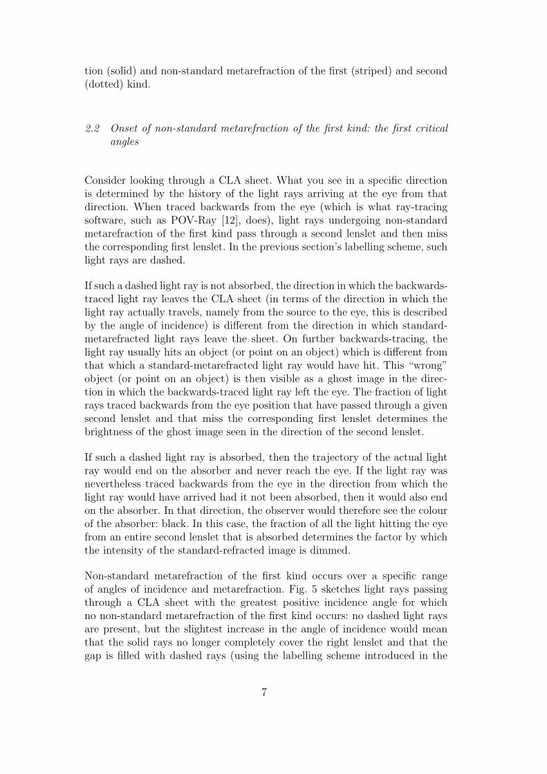
Non-standard metarefraction of the first kind occurs over a specific rangeof angles of incidence and metarefraction. Fig. 5 sketches light rays passingthrough a CLA sheet with the greatest positive incidence angle for whichno non-standard metarefraction of the first kind occurs: no dashed light raysare present, but the slightest increase in the angle of incidence would meanthat the solid rays no longer completely cover the right lenslet and that thegap is filled with dashed rays (using the labelling scheme introduced in the
7
< -1
+1 <
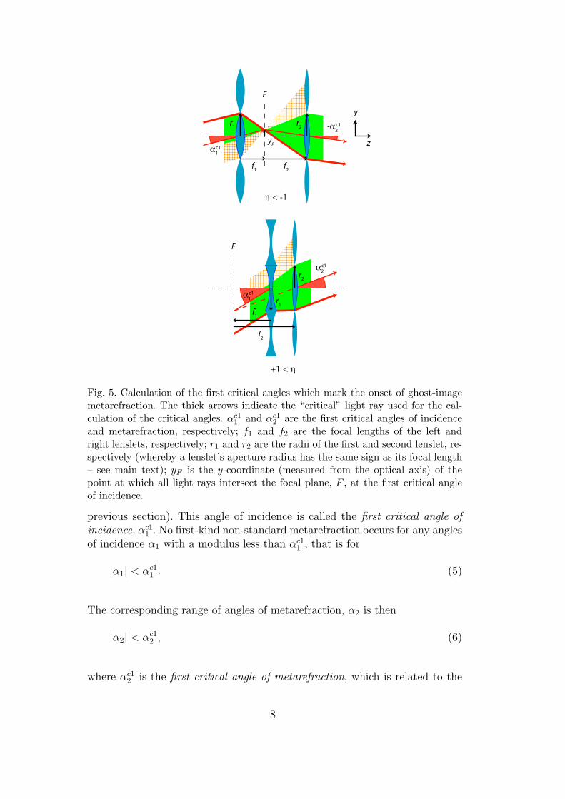
Fig. 5. Calculation of the first critical angles which mark the onset of ghost-imagemetarefraction. The thick arrows indicate the “critical” light ray used for the cal-culation of the critical angles. !c1
1 and !c12 are the first critical angles of incidence
and metarefraction, respectively; f1 and f2 are the focal lengths of the left andright lenslets, respectively; r1 and r2 are the radii of the first and second lenslet, re-spectively (whereby a lenslet’s aperture radius has the same sign as its focal length– see main text); yF is the y-coordinate (measured from the optical axis) of thepoint at which all light rays intersect the focal plane, F , at the first critical angleof incidence.
previous section). This angle of incidence is called the first critical angle ofincidence, !c1
1 . No first-kind non-standard metarefraction occurs for any anglesof incidence !1 with a modulus less than !c1
1 , that is for
|!1| < !c11 . (5)
The corresponding range of angles of metarefraction, !2 is then
|!2| < !c12 , (6)
where !c12 is the first critical angle of metarefraction, which is related to the
8
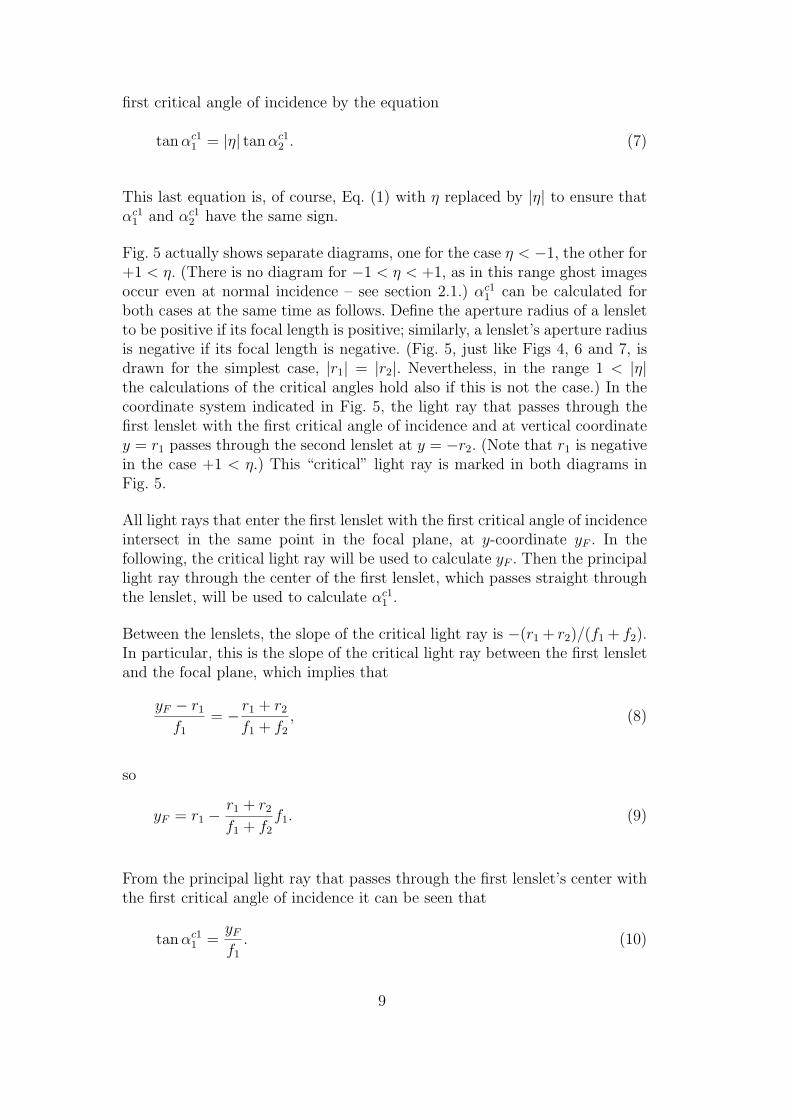
first critical angle of incidence by the equation
tan !c11 = |"| tan !c1
2 . (7)
This last equation is, of course, Eq. (1) with " replaced by |"| to ensure that!c1
1 and !c12 have the same sign.
Fig. 5 actually shows separate diagrams, one for the case " < !1, the other for+1 < ". (There is no diagram for !1 < " < +1, as in this range ghost imagesoccur even at normal incidence – see section 2.1.) !c1
1 can be calculated forboth cases at the same time as follows. Define the aperture radius of a lensletto be positive if its focal length is positive; similarly, a lenslet’s aperture radiusis negative if its focal length is negative. (Fig. 5, just like Figs 4, 6 and 7, isdrawn for the simplest case, |r1| = |r2|. Nevertheless, in the range 1 < |"|the calculations of the critical angles hold also if this is not the case.) In thecoordinate system indicated in Fig. 5, the light ray that passes through thefirst lenslet with the first critical angle of incidence and at vertical coordinatey = r1 passes through the second lenslet at y = !r2. (Note that r1 is negativein the case +1 < ".) This “critical” light ray is marked in both diagrams inFig. 5.
All light rays that enter the first lenslet with the first critical angle of incidenceintersect in the same point in the focal plane, at y-coordinate yF . In thefollowing, the critical light ray will be used to calculate yF . Then the principallight ray through the center of the first lenslet, which passes straight throughthe lenslet, will be used to calculate !c1
1 .
Between the lenslets, the slope of the critical light ray is !(r1 + r2)/(f1 + f2).In particular, this is the slope of the critical light ray between the first lensletand the focal plane, which implies that
yF ! r1
f1= ! r1 + r2
f1 + f2, (8)
so
yF = r1 !r1 + r2
f1 + f2f1. (9)
From the principal light ray that passes through the first lenslet’s center withthe first critical angle of incidence it can be seen that
tan !c11 =
yF
f1. (10)
9
Solving for !c11 and substituting the expression for yF in Eq. (9), this becomes
!c11 = tan!1
!r1
f1! r1 + r2
f1 + f2
"
. (11)
This is the expression for the first critical angle, valid in the range 1 < |"|.
It is useful to try out Eq. (11) for the simplest case (and for which the figuresare drawn), namely |r1| = |r2| = r. For a CLA sheet’s " value to fall into therange " < !1, its focal lengths have to satisfy the inequalities f1 > 0, f2 > 0,and f1 < f2 (Fig. 4). The fact that both focal lengths are positive means,according to our sign convention for aperture radii, that both aperture radiiare also positive, so r1 = r2 = r. Equation (11) then becomes
!c11 = tan!1
!r
f1! 2r
f1 + f2
"
= tan!1 r(f2 ! f1)
f1(f1 + f2).
(12)
As f1 < f2 and the values of all parameters in the argument of the inversetangent are positive, the critical angle !c1
1 is also positive. According to thedefinition of !c1
1 , Eq. (5), this means there is a range of incidence angles !1,centered around normal incidence, for which no non-standard metarefractionof the first kind occurs, which is what was expected from the discussion insection 2.1 and in this section so far.
In the case +1 < ", a CLA sheet’s focal lengths have to satisfy f1 < 0 andf2 > 0 according to Fig. 4. According to our sign convention, the apertureradii are then !r1 = r2 = r, so now Eq. (11) becomes
!c11 = tan!1 !r
f1. (13)
Reassuringly, as f1 < 0, !c11 is again positive.
2.3 Onset of non-standard metarefraction of the second kind: the second crit-ical angles
Whenever non-standard metarefraction of the second kind occurs, not all thelight that enters through the first lenslet subsequently passes through the cor-responding second lenslet. The standard-refracted image is therefore dimmed.Light that misses the corresponding second lenslet either leads to ghost im-ages at another angle of metarefraction, or (if filtered out with absorbers) itis absorbed entirely.
10
-1 < < 0
0 < < 1
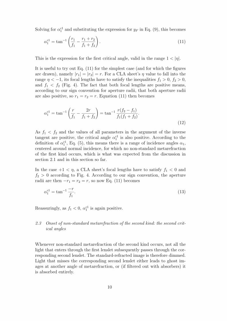
Fig. 6. Calculation of the second critical angles, which mark the onset of dimmingof standard-refracted light.
In analogy to the first critical angles, the second critical angles of incidenceand metarefraction, !c2
1 and !c22 , are respectively defined as the modulus of the
angle of incidence and metarefraction at which the dimming of the standard-refracted image starts to occur. Fig. 6 shows diagrams of light passing throughconfocal lenslet arrays at the second critical angles of incidence and metare-fraction, drawn for the cases !1 < " < 0 and 0 < " < 1. (For " < !1 and+1 < ", dimming occurs even at normal incidence.)
In a similar way to the derivation of the first critical angle of incidence, thesecond critical angle of metarefraction can be shown to be
!c22 = tan!1
!r2
f2! r1 + r2
f1 + f2
"
, (14)
from which the second critical angles of incidence can be calculated throughthe analog of Eq. (7),
tan !c21 = |"| tan !c2
2 . (15)
11
1 < 0 < < 1
< -1 -1 < < 0
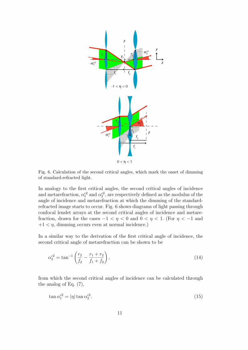
Fig. 7. Calculation of the third critical angles. Like in previous figures, the criticallight ray is indicated as a thick solid arrow.
The expressions for the second critical angles, Eqs. (14) and (15), are valid for|"| < 1.
2.4 Disappearance of standard metarefraction: the third critical angles
Under the assumptions for which the results presented in this section arederived, at least some normally-incident light is standard-refracted: in therange |"| < 1, all the normally incident light is standard-refracted; in therange |"| > 1, some of the light exits through the “wrong” lenslet and formsghost images at higher angles of metarefraction, but at least part of the lightpasses through the corresponding second lenslet and is therefore normallyrefracted. As the angle of incidence is increased beyond !c1
1 , the region ofstandard metarefraction shrinks and then disappears completely. The anglesof incidence and metarefraction for which standard metarefraction disappearsare called the third critical angles, !c3
1 and !c32 ; this case is shown in Fig. 7.
The calculation of the third critical angles starts with the observation that inall " ranges both third critical angles have to be positive as otherwise therewould be no standard metarefraction at normal incidence. This means that thethird critical angles are simply the absolute values of the angles of incidenceand metarefraction sketched in Fig. 7.
12
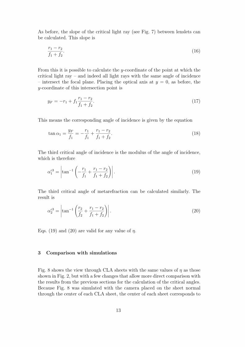
As before, the slope of the critical light ray (see Fig. 7) between lenslets canbe calculated. This slope is
r1 ! r2
f1 + f2. (16)
From this it is possible to calculate the y-coordinate of the point at which thecritical light ray – and indeed all light rays with the same angle of incidence– intersect the focal plane. Placing the optical axis at y = 0, as before, they-coordinate of this intersection point is
yF = !r1 + f1r1 ! r2
f1 + f2. (17)
This means the corresponding angle of incidence is given by the equation
tan !1 =yF
f1= !r1
f1+
r1 ! r2
f1 + f2. (18)
The third critical angle of incidence is the modulus of the angle of incidence,which is therefore
!c31 =
#####tan!1
!
!r1
f1+
r1 ! r2
f1 + f2
"##### . (19)
The third critical angle of metarefraction can be calculated similarly. Theresult is
!c32 =
#####tan!1
!r2
f2+
r1 ! r2
f1 + f2
"##### . (20)
Eqs. (19) and (20) are valid for any value of ".
3 Comparison with simulations
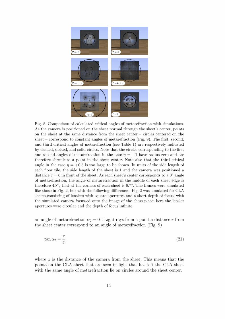
Fig. 8 shows the view through CLA sheets with the same values of " as thoseshown in Fig. 2, but with a few changes that allow more direct comparison withthe results from the previous sections for the calculation of the critical angles.Because Fig. 8 was simulated with the camera placed on the sheet normalthrough the center of each CLA sheet, the center of each sheet corresponds to
13
=-1
=-0.5
=2 =4
=+0.5
=-2
Fig. 8. Comparison of calculated critical angles of metarefraction with simulations.As the camera is positioned on the sheet normal through the sheet’s center, pointson the sheet at the same distance from the sheet center – circles centered on thesheet – correspond to constant angles of metarefraction (Fig. 9). The first, second,and third critical angles of metarefraction (see Table 1) are respectively indicatedby dashed, dotted, and solid circles. Note that the circles corresponding to the firstand second angles of metarefraction in the case " = !1 have radius zero and aretherefore shrunk to a point in the sheet center. Note also that the third criticalangle in the case " = +0.5 is too large to be shown. In units of the side length ofeach floor tile, the side length of the sheet is 1 and the camera was positioned adistance z = 6 in front of the sheet. As each sheet’s center corresponds to a 0" angleof metarefraction, the angle of metarefraction in the middle of each sheet edge istherefore 4.8", that at the corners of each sheet is 6.7". The frames were simulatedlike those in Fig. 2, but with the following di!erences: Fig. 2 was simulated for CLAsheets consisting of lenslets with square apertures and a short depth of focus, withthe simulated camera focussed onto the image of the chess piece; here the lensletapertures were circular and the depth of focus infinite.
an angle of metarefraction !2 = 0". Light rays from a point a distance r fromthe sheet center correspond to an angle of metarefraction (Fig. 9)
tan !2 =r
z, (21)
where z is the distance of the camera from the sheet. This means that thepoints on the CLA sheet that are seen in light that has left the CLA sheetwith the same angle of metarefraction lie on circles around the sheet center.
14
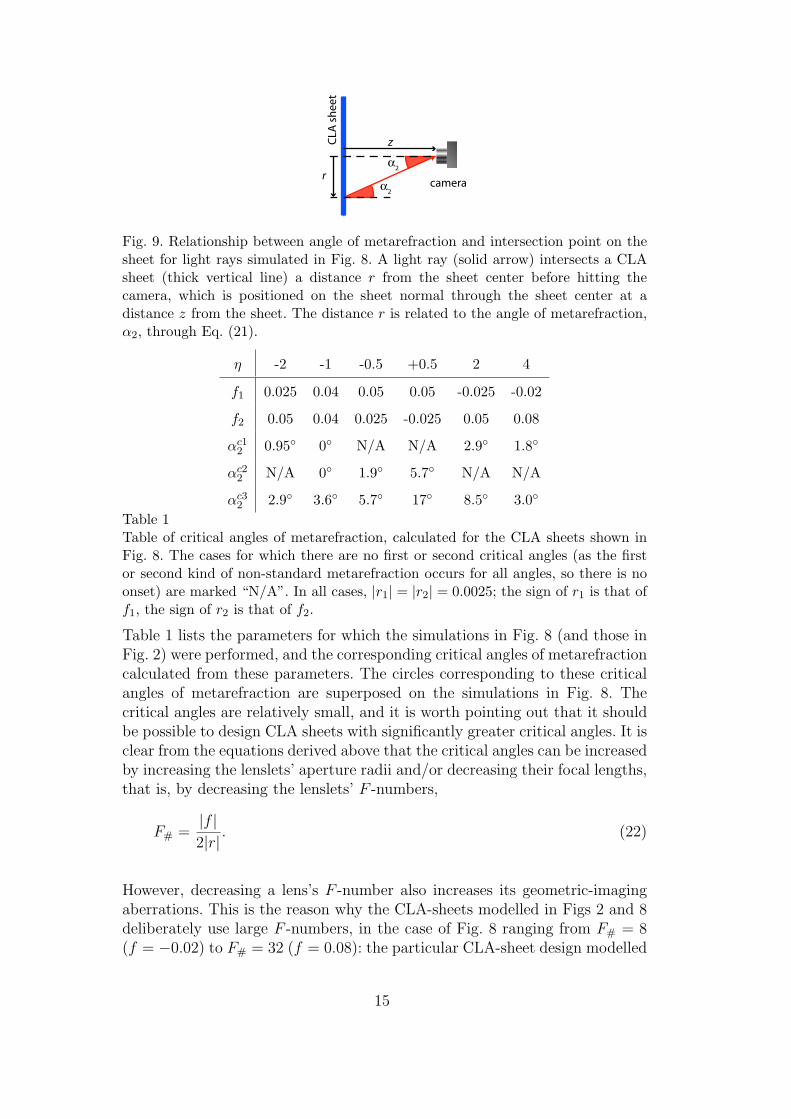
Fig. 9. Relationship between angle of metarefraction and intersection point on thesheet for light rays simulated in Fig. 8. A light ray (solid arrow) intersects a CLAsheet (thick vertical line) a distance r from the sheet center before hitting thecamera, which is positioned on the sheet normal through the sheet center at adistance z from the sheet. The distance r is related to the angle of metarefraction,!2, through Eq. (21).
" -2 -1 -0.5 +0.5 2 4
f1 0.025 0.04 0.05 0.05 -0.025 -0.02
f2 0.05 0.04 0.025 -0.025 0.05 0.08
!c12 0.95" 0" N/A N/A 2.9" 1.8"
!c22 N/A 0" 1.9" 5.7" N/A N/A
!c32 2.9" 3.6" 5.7" 17" 8.5" 3.0"
Table 1Table of critical angles of metarefraction, calculated for the CLA sheets shown inFig. 8. The cases for which there are no first or second critical angles (as the firstor second kind of non-standard metarefraction occurs for all angles, so there is noonset) are marked “N/A”. In all cases, |r1| = |r2| = 0.0025; the sign of r1 is that off1, the sign of r2 is that of f2.
Table 1 lists the parameters for which the simulations in Fig. 8 (and those inFig. 2) were performed, and the corresponding critical angles of metarefractioncalculated from these parameters. The circles corresponding to these criticalangles of metarefraction are superposed on the simulations in Fig. 8. Thecritical angles are relatively small, and it is worth pointing out that it shouldbe possible to design CLA sheets with significantly greater critical angles. It isclear from the equations derived above that the critical angles can be increasedby increasing the lenslets’ aperture radii and/or decreasing their focal lengths,that is, by decreasing the lenslets’ F -numbers,
F# =|f |2|r| . (22)
However, decreasing a lens’s F -number also increases its geometric-imagingaberrations. This is the reason why the CLA-sheets modelled in Figs 2 and 8deliberately use large F -numbers, in the case of Fig. 8 ranging from F# = 8(f = !0.02) to F# = 32 (f = 0.08): the particular CLA-sheet design modelled
15
in Figs 2 and 8, which was chosen because it had been implemented previously[1], only produces an acceptable imaging quality for large F -numbers 1 . Dif-ferent CLA designs should allow acceptable imaging quality in combinationwith significantly greater critical angles.
Perhaps the most obvious feature of Fig. 8 is that outside the (solid) circlecorresponding to the third critical angle of metarefraction the intensity fallsof very rapidly and very little light passes the sheet ouside this circle andreaches the camera. This confirms the considerations in section 2.4, accordingto which no light that has passed the sheet outside this circle should reachthe camera (Fig. 8 was calculated with absorbers that remove all light raysundergoing non-standard metarefraction), but only approximately: there isclearly some light that passes through the sheet just outside the solid circleand then reaches the camera, most notably in the case " = 4. The origin forthis “leakage” is not completely clear, but one possible reason could be thefact that in the simulations for Fig. 8, the apertures of corresponding lensletswere not separated exactly by the sum of the lenslets’ focal lengths. This is dueto the fact that corresponding lenslets are set up such that the centers of theiroutside surfaces were separated by the sum of the lenslets’ focal lengths, butbecause the lenslet surfaces are curved, the edges of corresponding lenslets– the e!ective apertures – were separated by a slightly di!erent distance.In the simulations, this separation is within less than 1% of the lens-centerseparation.
The light dimming due to non-standard metarefraction of the second kind isnot represented at all in our ray-tracing simulations. This can be understoodby the following argument which considers the light from an arbitrary smallpart of the chess piece’s surface that subsequently passes through a specificlenslet in the first lenslet array. Physically, for given lighting conditions thepower of this light is fixed; losing any of the power leads to dimming. Exactlysuch loss of power happens for angles above the second critical angles, asrepresented by the dotted light rays in the cases " < !1 and 1 < " in Fig.4: such light rays get refracted into the wrong angle of metarefraction, andare lost from the correct angle of metarefraction (in the case of Fig. 4, 0").However, if the solid light rays are traced backwards, none of the light appearslost in any way, so this particular dimming is consequently not represented.(Perhaps it is helpful to look at this in the following, slightly di!erent, way.The solid area in Fig. 4 can be seen as the standard-refracted beam. In thosecases where dotted light rays occur, namely " < !1 and 1 < ", the beam
1 Each CLA sheet consists of a single block of glass or transparent plastic (refractiveindex n) of thickness (f1 +f2)/n, whereby the lenslets of focal lengths f1 and f2 areformed by spherical surface dimples of radius f1(n! 1)/n and f2(n! 1)/n, respec-tively (see Fig. 1(c) in Ref. [1]). The modelled design was chosen because it shouldbe easy to manufacture; little attention was paid to field-of-view considerations.
16
diameter is smaller as it enters the first lenslet compared to when it leaves thesecond lenslet. This means that the power contained in the beam gets spreadacross a larger area, which should lead to a reduction in intensity.)
The e!ect of non-standard metarefraction of the first kind is represented inFig. 8, but its e!ect is far less obvious than that of the third critical angles.The e!ect of the lenslet arrays’ square symmetry obscures the e!ect further,for example in the frames corresponding to " = 2 and " = 4. Nevertheless,the dashed circle (which represent the first critical angles of metarefraction)arguably gives an indication of the size of the clear circle in the center of eachframe, most notably for " = 2 and " = 4.
4 Conclusions
This paper starts to study optical imperfections of generalized CLA sheets,specifically light passing through non-corresponding lenslets, which leads tonon-standard metarefraction.
The formulae that were derived for the critical angles contain only the focallengths of the lenslets and the radius of each lenslet. They therefore provide aclear guide on what needs to be done to increase the field of view. However, itshould be noted that an increase in the radius of each lenslet aperture withouta corresponding increase in the focal length increases the angle at which lightrays travel, and with it aberrations, unless great care is taken in the lens design.Therefore the field of view needs to be traded o! against imaging quality.
Several questions remain. In this paper only the simplest generalized CLAswere studied, so it is natural to examine the critical angles for more complex,generalized, CLAs [3]. Similarly, little is known about the field of view ofthe closely related Dove-prism sheets [4], and of combinations of Dove-prismsheets that perform negative metarefraction [5] and light-ray rotation [6].
We have recently started to realize experimentally CLAs from lenticular ar-rays intended for lenticular printing, the technique used to create images thatchange when viewed from di!erent directions [24]. As a first step we havedemonstrated arrays of confocal cylindrical lenses which act like METATOYsthat flip one transverse component of the light-ray direction [25]. In futurewe intend to combine lenticular arrays with di!erent focal lengths so thatthey act like arrays of confocal elliptical lenses, which are examples of gen-eralized CLAs [3]. Using the fabrication and alignment techniques developedfor complex micro-optical systems [26], it should be possible to build muchhigher-quality – and more general – generalized CLAs.
17
Acknowledgments
JC is a Royal Society University Research Fellow.
References
[1] J. Courtial, “Ray-optical refraction with confocal lenslet arrays,” New J. Phys.10, 083033 (2008).
[2] A. C. Hamilton and J. Courtial, “Metamaterials for light rays: ray opticswithout wave-optical analog in the ray-optics limit,” New J. Phys. 11, 013042(2009).
[3] A. C. Hamilton and J. Courtial, “Generalized refraction using lenslet arrays,”J. Opt. A: Pure Appl. Opt. 11, 065502 (2009).
[4] A. C. Hamilton and J. Courtial, “Optical properties of a Dove-prism sheet,” J.Opt. A: Pure Appl. Opt. 10, 125302 (2008).
[5] J. Courtial and J. Nelson, “Ray-optical negative refraction and pseudoscopicimaging with Dove-prism arrays,” New J. Phys. 10, 023028 (2008).
[6] A. C. Hamilton, B. Sundar, J. Nelson, and J. Courtial, “Local light-rayrotation,” arXiv:0809.2646 [physics.optics] (2009).
[7] D. R. Smith, J. B. Pendry, and M. C. K. Wiltshire, “Metamaterials and NegativeRefractive Index,” Science 305, 788–792 (2004).
[8] V. G. Veselago, “The electrodynamics of sustances with simultaneously negativevalues of # and µ,” Sov. Phys. Uspekhi 10, 509–514 (1968).
[9] J. B. Pendry, “Negative refraction makes a perfect lens,” Phys. Rev. Lett. 85,3966–3969 (2000).
[10] Z. Liu, H. Lee, Y. Xiong, C. Sun, and X. Zhang, “Far-Field Optical HyperlensMagnifying Sub-Di!raction-Limited Objects,” Science 315, 1686 (2007).
[11] I. I. Smolyaninov, Y.-J. Hung, and C. C. Davis, “Magnifying Superlens in theVisible Frequency Range,” Science 315, 1699–1701 (2007).
[12] “POV-Ray – The Persistence of Vision Raytracer,” http://www.povray.org/.
[13] G. Lippmann, “La photographie integrale,” C. R. Hebd. Seances Acad. Sci.146, 446–451 (1908).
[14] K. Anderson, “Lenticular device and method for providing same,” U. S. Patent3,538,632 (1970).
[15] T. Okoshi, “Three-dimensional displays,” Proc. IEEE 68, 548–564 (1980).
18
[16] M. von den Ho! and G. Flinn, “E!ective 3D displays using large area lenticulararrays,” Photonic international 2008/1 pp. 74–77 (2008).
[17] J. Tanida, T. Kumagai, K. Yamada, S. Miyatake, K. Ishida, T. Morimoto,N. Kondou, D. Miyazaki, and Y. Ichioka, “Thin Observation Module by BoundOptics (TOMBO): Concept and Experimental Verification,” Appl. Opt. 40,1806–1813 (2001).
[18] R. Athale, D. M. Healy, D. J. Brady, and M. A. Neifeld, “Reinventing thecamera,” OPN 19, 32–37 (2008).
[19] A. V. Kanaev, D. A. Scribner, J. R. Ackerman, and E. F. Fleet, “Analysis andapplication of multiframe superresolution processing for conventional imagingsystems and lenslet arrays,” Appl. Opt. 46, 4320–4328 (2007).
[20] S. Daniell, “Correction of aberrations in lens-based 3D displays,” Proc. SPIE5664, 175–185 (2005).
[21] N. Davies and M. McCormick, “Imaging system,” International Patent WO93/20473 (1993).
[22] R. F. Stevens and T. G. Harvey, “Lens arrays for a three-dimensional imagingsystem,” J. Opt. A: Pure Appl. Opt. 4, S17–S21 (2002).
[23] F. Okano and J. Arai, “Optical shifter for a three-dimensional image by use ofa gradient-index lens array,” Appl. Opt. 41, 4140–4147 (2002).
[24] Wikipedia, “Lenticular printing,”http://en.wikipedia.org/wiki/Lenticular printing (2009).
[25] M. Blair, L. Clark, E. A. Houston, G. Smith, J. Leach, A. C. Hamilton,and J. Courtial, “Experimental demonstration of a light-ray-direction-flipping METATOY based on confocal lenticular arrays,” arXiv:0902.3192[physics.optics] (2009).
[26] W. Singer and K. H. Brenner, “Stacked micro-optical systems,” in “Micro-Optics,” , H. P. Herzig, ed. (Taylor & Francis Ltd, 1997), pp. 199–221.
19