Embed Size (px)
Citation preview
STANDARD AND FIBROPTIC THERMOMETERS
abcdefgabc
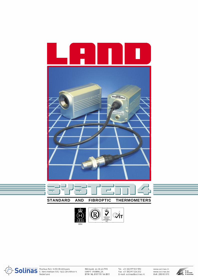
INFRARED APPLICATIONSNon contact temperature measuring systems are designed forcontinuous quality and process monitoring and control in a widerange of industries including:- Iron & Steel, Glass, Plastics,Rubber, Minerals, Paper... and many more.
With measurement capabilities from 0 to 2600°C, infraredthermometers measure both the product being processed andthe plant and machinery used in the production. Here are just afew of the processes where SYSTEM 4 can solve yourmeasurement problems:-
Metal ProductionSmelting, refining, pouring, continuous casting,slabbing, reheating, rolling, drawing, coiling,extruding, coating, annealing, stamping, pressing,forging, sintering, galvanising, heat treatment...
Glass ProductionMelting, refining, firing, gob formation, furnaces,floating, moulding, toughening, laminating, fibredrawing, vapour deposition, preforming...
Mineral ProcessingFiring, mixing, drying, storing, conveying, laying...
PaperRolling, drying, calendering, coating, printing,photographic, curing..
Plastics & RubberThick & thin film plastics, blown film, thermoforming,calendering, orientation, extruding, mixing, shrinking,laminating, moulding...
ChemicalCatalyst beds, powder drying, mixing, furnaces,thermal reactors...
Food & PharmaceuticalsFreezing, moulding, extruding, sterilising, tablet drying,labelling, sealing...
ElectronicsWave soldering, glass coating, circuit board testing,doping...
There is a choice of thermometer type to match your temperaturerequirements and process.
Single wavelength thermometers are intended for general purposeuse as well as solving problems in specific applications.
Ratio thermometers are used in difficult environments containingsteam, smoke, or dust, or where the target does not completelyfill the field of view.
Fibroptic thermometers are used to measure the temperature ofmaterials where the target is difficult to access.
The use of fibre optics is most effective in high temperature, highmagnetic fields etc. which would prevent location of other sensors.
SYSTEM 4 THERMOMETERSSYSTEM 4 comprises an advanced rangeof high precision radiation thermometers,LANDMARK® processors and a range ofmounting accessories which combine toform a complete temperaturemeasurement system.SYSTEM 4 thermometers offer exceptionalflexibility with a choice of singlewavelength, ratio, fibroptic and fibropticratio models.Thermometer type, temperature range, spectralresponse and optical characteristics are chosen to suitany application from 0 to 2600°C.• Focusable optics - standard and short focus versions
with through-the-lens sighting providing clear andguaranteed definition of target
• Optional close-up lenses - giving measurement oftargets as small as 0.45mm
• Accurate, reliable, drift-free measurement• Rugged design with a range of mounting options• Flexible fibre optics light guide versions - with optional
laser targeting system to define target spot• High level linear output
RADIATION THERMOMETERSProven, reliable electronics and a high quality optical systemcombine to give a thermometer which delivers accurate,dependable temperature measurement. A rugged die-castaluminium body, with a high quality electrical connector, ensuresreliable performance.
Standard bodied thermometers all feature through-the-lenssighting with a 6° field of view. Adjustable focus with a circulargraticule gives precise alignment on to the smallest of targets. Twooptical variants are available: Standard focus - adjustablebetween 500mm and infinity, and Short-focus - viewing from350mm to 1m. Close-up lenses are also available which canmeasure targets as small as 0.45mm from as close as 90mm.
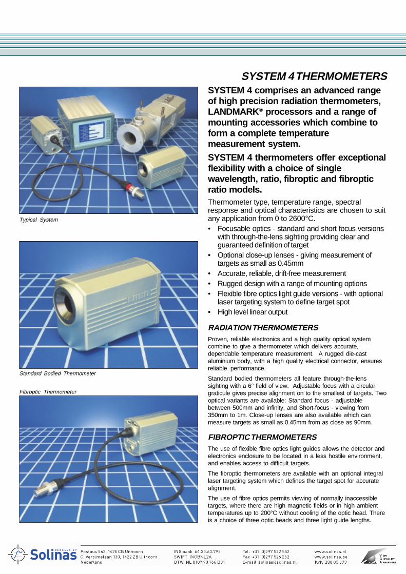
FIBROPTIC THERMOMETERSThe use of flexible fibre optics light guides allows the detector andelectronics enclosure to be located in a less hostile environment,and enables access to difficult targets.
The fibroptic thermometers are available with an optional integrallaser targeting system which defines the target spot for accuratealignment.
The use of fibre optics permits viewing of normally inaccessibletargets, where there are high magnetic fields or in high ambienttemperatures up to 200°C without cooling of the optic head. Thereis a choice of three optic heads and three light guide lengths.
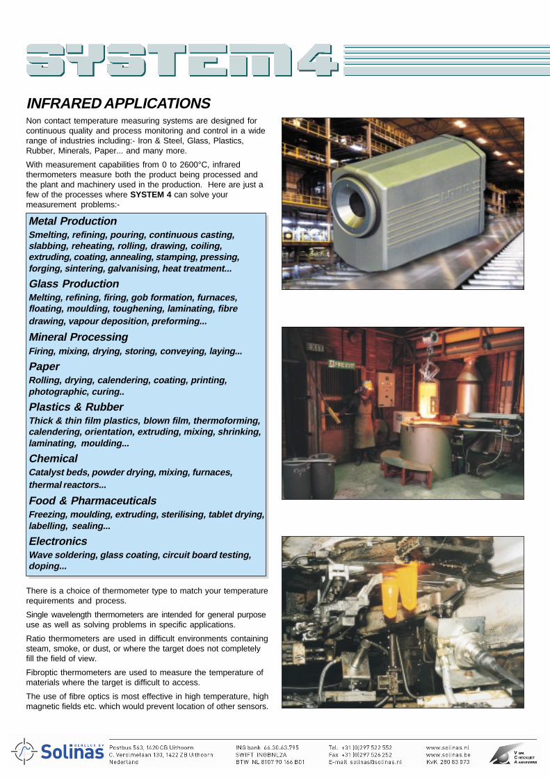
Typical System
Standard Bodied Thermometer
Fibroptic Thermometer
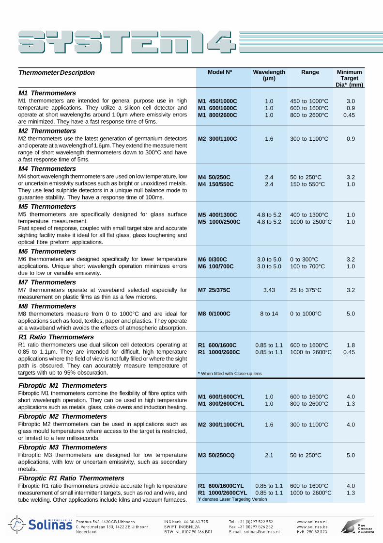
M1 ThermometersM1 thermometers are intended for general purpose use in hightemperature applications. They utilize a silicon cell detector andoperate at short wavelengths around 1.0µm where emissivity errorsare minimized. They have a fast response time of 5ms.
M2 ThermometersM2 thermometers use the latest generation of germanium detectorsand operate at a wavelength of 1.6µm. They extend the measurementrange of short wavelength thermometers down to 300°C and havea fast response time of 5ms.
M4 ThermometersM4 short wavelength thermometers are used on low temperature, lowor uncertain emissivity surfaces such as bright or unoxidized metals.They use lead sulphide detectors in a unique null balance mode toguarantee stability. They have a response time of 100ms.
M5 ThermometersM5 thermometers are specifically designed for glass surfacetemperature measurement.Fast speed of response, coupled with small target size and accuratesighting facility make it ideal for all flat glass, glass toughening andoptical fibre preform applications.
M6 ThermometersM6 thermometers are designed specifically for lower temperatureapplications. Unique short wavelength operation minimizes errorsdue to low or variable emissivity.
M7 ThermometersM7 thermometers operate at waveband selected especially formeasurement on plastic films as thin as a few microns.
M8 ThermometersM8 thermometers measure from 0 to 1000°C and are ideal forapplications such as food, textiles, paper and plastics. They operateat a waveband which avoids the effects of atmospheric absorption.
R1 Ratio ThermometersR1 ratio thermometers use dual silicon cell detectors operating at0.85 to 1.1µm. They are intended for difficult, high temperatureapplications where the field of view is not fully filled or where the sightpath is obscured. They can accurately measure temperature oftargets with up to 95% obscuration.
Fibroptic M1 ThermometersFibroptic M1 thermometers combine the flexibility of fibre optics withshort wavelength operation. They can be used in high temperatureapplications such as metals, glass, coke ovens and induction heating.
Fibroptic M2 ThermometersFibroptic M2 thermometers can be used in applications such asglass mould temperatures where access to the target is restricted,or limited to a few milliseconds.
Fibroptic M3 ThermometersFibroptic M3 thermometers are designed for low temperatureapplications, with low or uncertain emissivity, such as secondarymetals.
Fibroptic R1 Ratio ThermometersFibroptic R1 ratio thermometers provide accurate high temperaturemeasurement of small intermittent targets, such as rod and wire, andtube welding. Other applications include kilns and vacuum furnaces.
Thermometer Description Model Nº Wavelength Range Minimum(µm) Target
Dia* (mm)
M1 450/1000C 1.0 450 to 1000°C 3.0M1 600/1600C 1.0 600 to 1600°C 0.9M1 800/2600C 1.0 800 to 2600°C 0.45
M2 300/1100C 1.6 300 to 1100°C 0.9
M4 50/250C 2.4 50 to 250°C 3.2M4 150/550C 2.4 150 to 550°C 1.0
M5 400/1300C 4.8 to 5.2 400 to 1300°C 1.0M5 1000/2500C 4.8 to 5.2 1000 to 2500°C 1.0
M6 0/300C 3.0 to 5.0 0 to 300°C 3.2M6 100/700C 3.0 to 5.0 100 to 700°C 1.0
M7 25/375C 3.43 25 to 375°C 3.2
M8 0/1000C 8 to 14 0 to 1000°C 5.0
R1 600/1600C 0.85 to 1.1 600 to 1600°C 1.8R1 1000/2600C 0.85 to 1.1 1000 to 2600°C 0.45
* When fitted with Close-up lens
M1 600/1600CYL 1.0 600 to 1600°C 4.0M1 800/2600CYL 1.0 800 to 2600°C 1.3
M2 300/1100CYL 1.6 300 to 1100°C 4.0
M3 50/250CQ 2.1 50 to 250°C 5.0
R1 600/1600CYL 0.85 to 1.1 600 to 1600°C 4.0R1 1000/2600CYL 0.85 to 1.1 1000 to 2600°C 1.3Y denotes Laser Targeting Version
(1) Time quoted to 95% of step change (2) Accuracy quoted to ITS90 (3) Above 75°C (4) Optimised for glass toughening = 3K at 630°C Y Denotes laser targeting system available
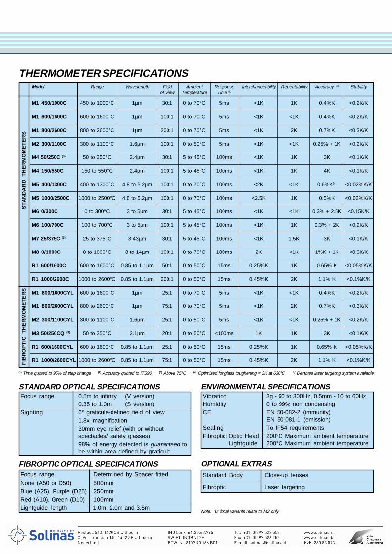
Model Range Wavelength Field Ambient Response Interchangeability Repeatability Accuracy (2) Stabilityof View Temperature Time (1)
M1 450/1000C 450 to 1000°C 1µm 30:1 0 to 70°C 5ms <1K 1K 0.4%K <0.2K/K
M1 600/1600C 600 to 1600°C 1µm 100:1 0 to 70°C 5ms <1K <1K 0.4%K <0.2K/K
M1 800/2600C 800 to 2600°C 1µm 200:1 0 to 70°C 5ms <1K 2K 0.7%K <0.3K/K
M2 300/1100C 300 to 1100°C 1.6µm 100:1 0 to 50°C 5ms <1K <1K 0.25% + 1K <0.2K/K
M4 50/250C (3) 50 to 250°C 2.4µm 30:1 5 to 45°C 100ms <1K 1K 3K <0.1K/K
M4 150/550C 150 to 550°C 2.4µm 100:1 5 to 45°C 100ms <1K 1K 4K <0.1K/K
M5 400/1300C 400 to 1300°C 4.8 to 5.2µm 100:1 0 to 70°C 100ms <2K <1K 0.6%K(4) <0.02%K/K
M5 1000/2500C 1000 to 2500°C 4.8 to 5.2µm 100:1 0 to 70°C 100ms <2.5K 1K 0.5%K <0.02%K/K
M6 0/300C 0 to 300°C 3 to 5µm 30:1 5 to 45°C 100ms <1K <1K 0.3% + 2.5K <0.15K/K
M6 100/700C 100 to 700°C 3 to 5µm 100:1 5 to 45°C 100ms <1K 1K 0.3% + 2K <0.2K/K
M7 25/375C (3) 25 to 375°C 3.43µm 30:1 5 to 45°C 100ms <1K 1.5K 3K <0.1K/K
M8 0/1000C 0 to 1000°C 8 to 14µm 100:1 0 to 70°C 100ms 2K <1K 1%K + 1K <0.3K/K
R1 600/1600C 600 to 1600°C 0.85 to 1.1µm 50:1 0 to 50°C 15ms 0.25%K 1K 0.65% K <0.05%K/K
R1 1000/2600C 1000 to 2600°C 0.85 to 1.1µm 200:1 0 to 50°C 15ms 0.45%K 2K 1.1% K <0.1%K/K
M1 600/1600CYL 600 to 1600°C 1µm 25:1 0 to 70°C 5ms <1K <1K 0.4%K <0.2K/K
M1 800/2600CYL 800 to 2600°C 1µm 75:1 0 to 70°C 5ms <1K 2K 0.7%K <0.3K/K
M2 300/1100CYL 300 to 1100°C 1.6µm 25:1 0 to 50°C 5ms <1K <1K 0.25% + 1K <0.2K/K
M3 50/250CQ (3) 50 to 250°C 2.1µm 20:1 0 to 50°C <100ms 1K 1K 3K <0.1K/K
R1 600/1600CYL 600 to 1600°C 0.85 to 1.1µm 25:1 0 to 50°C 15ms 0.25%K 1K 0.65% K <0.05%K/K
R1 1000/2600CYL 1000 to 2600°C 0.85 to 1.1µm 75:1 0 to 50°C 15ms 0.45%K 2K 1.1% K <0.1%K/K
THERMOMETER SPECIFICATIONS
ENVIRONMENTAL SPECIFICATIONSVibration 3g - 60 to 300Hz, 0.5mm - 10 to 60HzHumidity 0 to 99% non condensingCE EN 50-082-2 (immunity)
EN 50-081-1 (emission)Sealing To IP54 requirementsFibroptic: Optic Head 200°C Maximum ambient temperature
Lightguide 200°C Maximum ambient temperature
OPTIONAL EXTRASStandard Body Close-up lenses
Fibroptic Laser targeting
FIBROPTIC OPTICAL SPECIFICATIONSFocus range Determined by Spacer fitted
None (A50 or D50) 500mmBlue (A25), Purple (D25) 250mmRed (A10), Green (D10) 100mm
Lightguide length 1.0m, 2.0m and 3.5m
STANDARD OPTICAL SPECIFICATIONSFocus range 0.5m to infinity (V version)
0.35 to 1.0m (S version)Sighting 6° graticule-defined field of view
1.8x magnification30mm eye relief (with or withoutspectacles/ safety glasses)98% of energy detected is guaranteed tobe within area defined by graticule
ST
AN
DA
RD
TH
ER
MO
ME
TE
RS
FIB
RO
PT
IC T
HE
RM
OM
ET
ER
S
Note: 'D' focal variants relate to M3 only
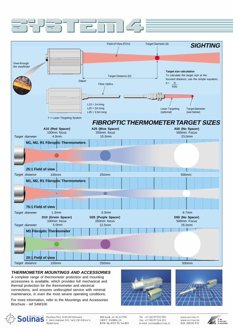
THERMOMETER MOUNTINGS AND ACCESSORIESA complete range of thermometer protection and mountingaccessories is available, which provides full mechanical andthermal protection for the thermometer and electricalconnections, and ensures undisrupted service with minimalmaintenance, in even the most severe operating conditions.
For more information, refer to the Mountings and AccessoriesBrochure - ref S4M100
SIGHTING
Datum
Target Distance (D)
Field of View (FOV) Target Diameter (d)
View throughthe viewfinder
FIBROPTIC THERMOMETER TARGET SIZES
Target size calculationTo calculate the target size at thefocused distance, use the simple equation;d = D
FOVFibre Optics
Y = Laser Targeting System
L10 = 1m longL20 = 2m longL35 = 3.5m long
Laser Targeting(optional)
Target diameter(see below)
A50 (No Spacer)500mm Focus
Target diameter
A10 (Red Spacer)100mm focus
A25 (Blue Spacer)250mm focus
4.0mm 10.0mm 23.0mm
M1, M2, R1 Fibroptic Thermometers
25:1 Field of view
100mm 500mmTarget distance 250mm
M1, M2, R1 Fibroptic Thermometers
75:1 Field of view
D50 (No Spacer)500mm Focus
100mm 500mmTarget distance
M3 Fibroptic Thermometer
20:1 Field of view
D10 (Green Spacer)100mm focus
D25 (Purple Spacer)250mm focus
250mm
25.0mm12.5mm5.0mm
Target diameter 1.3mm 3.3mm 6.7mm
Target diameter
M 1 6 0 0 1 6 0 0 C V 1 0 A 1 0Y
VSLQ
CF
12345678
1 0 A 1 0
MR
A10A25A50D10D25D50
A
D
A10A25A50D10D25D50
A
D
L10L20L35Q10Q20Q35
L
Q
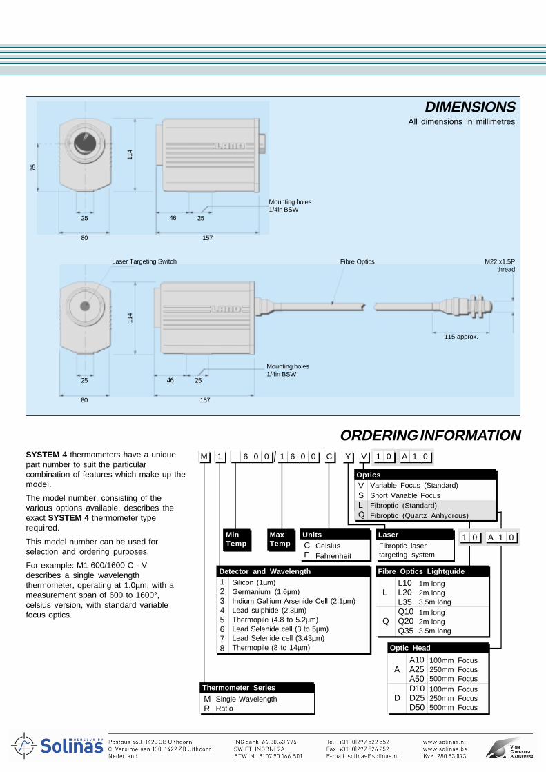
DIMENSIONSAll dimensions in millimetres
157
46 25
80
25
114
75
Mounting holes1/4in BSW
Laser Targeting Switch
157
46 25
80
25
114
Mounting holes1/4in BSW
Fibre Optics M22 x1.5Pthread
115 approx.
ORDERING INFORMATIONSYSTEM 4 thermometers have a uniquepart number to suit the particularcombination of features which make up themodel.
The model number, consisting of thevarious options available, describes theexact SYSTEM 4 thermometer typerequired.
This model number can be used forselection and ordering purposes.
For example: M1 600/1600 C - Vdescribes a single wavelengththermometer, operating at 1.0µm, with ameasurement span of 600 to 1600°,celsius version, with standard variablefocus optics.
Variable Focus (Standard)Short Variable FocusFibroptic (Standard)Fibroptic (Quartz Anhydrous)
MinTemp
Units Laser
Thermometer Series
CelsiusFahrenheit
Fibroptic lasertargeting system
Single WavelengthRatio
Silicon (1µm)Germanium (1.6µm)Indium Gallium Arsenide Cell (2.1µm)Lead sulphide (2.3µm)Thermopile (4.8 to 5.2µm)Lead Selenide cell (3 to 5µm)Lead Selenide cell (3.43µm)Thermopile (8 to 14µm)
Optics
Fibre Optics Lightguide
Optic Head
MaxTemp
100mm Focus250mm Focus500mm Focus100mm Focus250mm Focus500mm Focus
Detector and Wavelength
1m long2m long3.5m long1m long2m long3.5m long
Printed in England Continuous product development may make it necessary to change these details without notice. S4T101E/0303
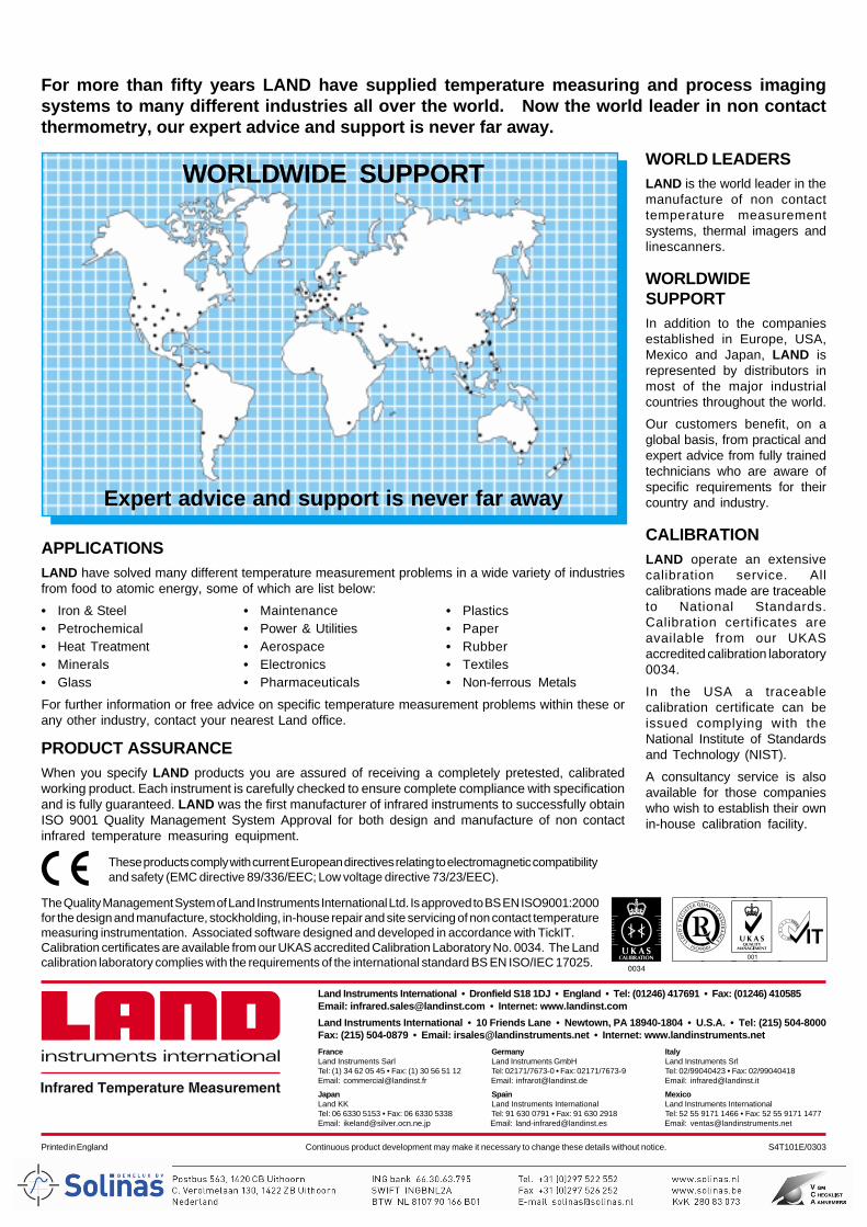
For more than fifty years LAND have supplied temperature measuring and process imagingsystems to many different industries all over the world. Now the world leader in non contactthermometry, our expert advice and support is never far away.
WORLD LEADERSLAND is the world leader in themanufacture of non contacttemperature measurementsystems, thermal imagers andlinescanners.
WORLDWIDESUPPORTIn addition to the companiesestablished in Europe, USA,Mexico and Japan, LAND isrepresented by distributors inmost of the major industrialcountries throughout the world.
Our customers benefit, on aglobal basis, from practical andexpert advice from fully trainedtechnicians who are aware ofspecific requirements for theircountry and industry.
CALIBRATIONLAND operate an extensivecalibration service. Allcalibrations made are traceableto National Standards.Calibration certificates areavailable from our UKASaccredited calibration laboratory0034.
In the USA a traceablecalibration certificate can beissued complying with theNational Institute of Standardsand Technology (NIST).
A consultancy service is alsoavailable for those companieswho wish to establish their ownin-house calibration facility.
APPLICATIONSLAND have solved many different temperature measurement problems in a wide variety of industriesfrom food to atomic energy, some of which are list below:
• Iron & Steel • Maintenance • Plastics• Petrochemical • Power & Utilities • Paper• Heat Treatment • Aerospace • Rubber• Minerals • Electronics • Textiles• Glass • Pharmaceuticals • Non-ferrous Metals
For further information or free advice on specific temperature measurement problems within these orany other industry, contact your nearest Land office.
PRODUCT ASSURANCEWhen you specify LAND products you are assured of receiving a completely pretested, calibratedworking product. Each instrument is carefully checked to ensure complete compliance with specificationand is fully guaranteed. LAND was the first manufacturer of infrared instruments to successfully obtainISO 9001 Quality Management System Approval for both design and manufacture of non contactinfrared temperature measuring equipment.
These products comply with current European directives relating to electromagnetic compatibilityand safety (EMC directive 89/336/EEC; Low voltage directive 73/23/EEC).
WORLDWIDE SUPPORT
Expert advice and support is never far away
The Quality Management System of Land Instruments International Ltd. Is approved to BS EN ISO9001:2000for the design and manufacture, stockholding, in-house repair and site servicing of non contact temperaturemeasuring instrumentation. Associated software designed and developed in accordance with TickIT.Calibration certificates are available from our UKAS accredited Calibration Laboratory No. 0034. The Landcalibration laboratory complies with the requirements of the international standard BS EN ISO/IEC 17025.
A
Land Instruments International • Dronfield S18 1DJ • England • Tel: (01246) 417691 • Fax: (01246) 410585Email: [email protected] • Internet: www.landinst.com
Land Instruments International • 10 Friends Lane • Newtown, PA 18940-1804 • U.S.A. • Tel: (215) 504-8000Fax: (215) 504-0879 • Email: [email protected] • Internet: www.landinstruments.net
France Germany ItalyLand Instruments Sarl Land Instruments GmbH Land Instruments SrlTel: (1) 34 62 05 45 • Fax: (1) 30 56 51 12 Tel: 02171/7673-0 • Fax: 02171/7673-9 Tel: 02/99040423 • Fax: 02/99040418Email: [email protected] Email: [email protected] Email: [email protected]
Japan Spain MexicoLand KK Land Instruments International Land Instruments InternationalTel: 06 6330 5153 • Fax: 06 6330 5338 Tel: 91 630 0791 • Fax: 91 630 2918 Tel: 52 55 9171 1466 • Fax: 52 55 9171 1477Email: [email protected] Email: [email protected] Email: [email protected]
abcdefgabc
abcdefgabc
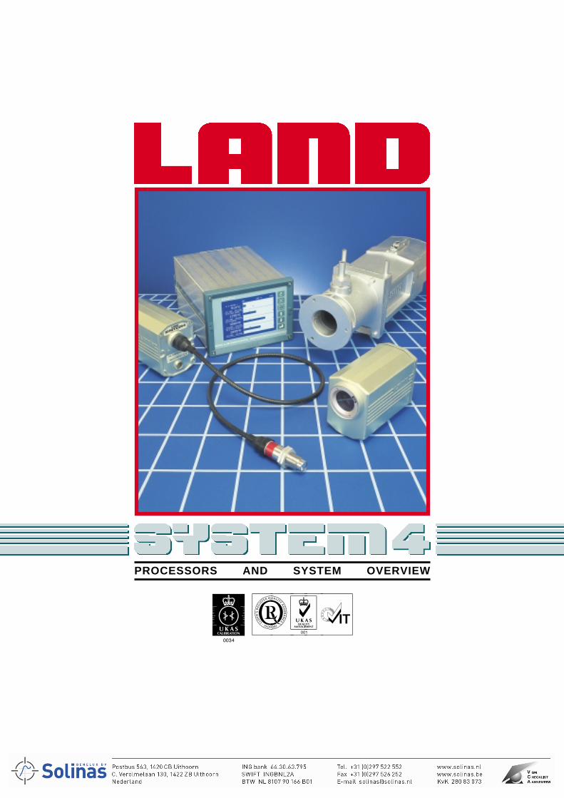
PROCESSORS AND SYSTEM OVERVIEW
For over 50 years, Land have been theworld leaders in delivering solutions totemperature measurement problems.
The new family of products, combiningunrivalled expertise and design know-how with the latest technology is...
SYSTEM 4 gives you a choice ofproducts which covers all applications,environments and budgets, ensuringpremium performance at competitiveprices. Compatibility andinterchangeability of each productensures maximum flexibility, both attime of purchase and subsequently foreasy maintenance.Non contact temperature measuring systems are designed forcontinuous quality and process monitoring and control in a widerange of industries. They can be used in a variety of applicationssuch as metal production, processing, foundry and forging, glass,electronics, mineral processing and petrochemical whereaccurate measurement of temperature is vital.
No other method of temperature measurement offers thebenefits of non contact infrared radiation thermometry.
• Infrared radiation thermometer systems measure continuouslythe temperature of hot, moving or normally inaccessiblematerials accurately and safely at a distance.
• Sensing heads do not require contact with the target object,and therefore cannot interfere with, damage or contaminatethe product they are measuring.
• Thermometers do not remove heat or disturb the processbeing monitored and offer the only solution when the productis small, fragile or in a vacuum or controlled atmosphere.
SYSTEM 4 gives you a wide choice of compatible items to ensurethe system you buy is optimized to meet the needs of yourapplication, budget and environment.
LANDMARK® processors are designed to produce the processcontrol variables you need from ANY of the SYSTEM 4 sensors.With this total compatibility, you are free to choose a processor togive the features and performance you need and select thesensor type best suited to the application. All SYSTEM 4processors and sensors are calibrated individually to guaranteeinterchangeability and hence easy maintenance for many years.
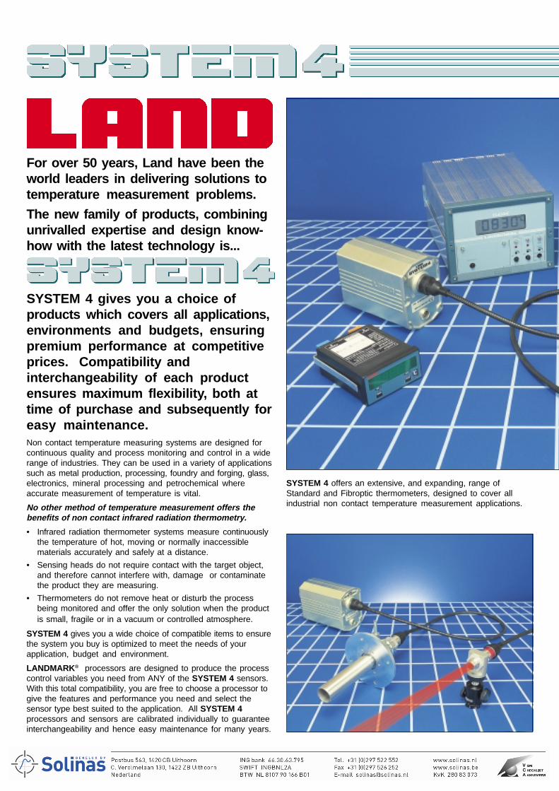
SYSTEM 4 offers an extensive, and expanding, range ofStandard and Fibroptic thermometers, designed to cover allindustrial non contact temperature measurement applications.
PROCESSORSThe heart of any temperature measurement system is the signalprocessor. A LANDMARK® signal processor puts the controls ofyour system where you need them - panel mounted or DIN railmounted, the choice is yours. SYSTEM 4 uses high speedinputs, real time signal processing and flexible outputs toconvert the output of each sensor into real process variables.LANDMARK® GRAPHIC is the state-of-the-art, panel mountedsignal processor, designed to control and process data from anySYSTEM 4 Thermometer. The Multi-channel processor accepts,processes and displays inputs from any combination of up to fourseparate thermometers simultaneously - it is not multiplexed.Multiple outputs are provided which can be integrated directlyinto any process monitoring, recording or control system.LANDMARK® GRAPHIC processors offer a variety of featuresand advanced time functions which present temperature data in achoice of displays and outputs to suit the particular application.LANDMARK® GRAPHIC processors are rugged, and extremelyversatile, utilizing the latest technology available, giving you morechoice and more precision in the measurement of temperature.For applications which do not require this high level of processorpower, a simple alternative is available - LANDMARK® CLASSIC.LANDMARK® CLASSIC can be used with any SYSTEM 4Thermometer. It displays the measured temperature and optionalplug-in cards give you a choice of either a peak picker oraverager time function, plus up to two alarm modules.LANDMARK® TECHNIC is a high precision, DIN-rail mountedintelligent digital processor. Its features include adjustableemissivity/non-greyness, peak picker, averager, track and hold,alarm and 4 to 20mA outputs, and RS232C serialcommunications for set up via a PC.LANDMARK® BASIC is a simple DIN-rail mounted signalprocessing unit, providing simple signal conditioning witheconomy and versatility.
THERMOMETERSInfrared radiation thermometers do not require contact with thetarget object, so they cannot interfere with, damage, orcontaminate the product they are measuring. They do notremove heat or disturb the process being monitored and offer theonly solution when the product is moving, small, fragile, or in avacuum or controlled atmosphere.SYSTEM 4 Thermometers all feature temperature spans andoperating wavebands selected to ensure optimum accuracy ofmeasurement for each application.Any SYSTEM 4 thermometer, selected from the extensive rangeavailable, can be used with any SYSTEM 4 LANDMARK®
processor, allowing you to build a temperature measurementsystem designed specifically to your application requirements.Standard thermometers feature precision through-the-lensfocusable optics which guarantee exact viewing and accuratemeasurement of the smallest of target areas.Single wavelength thermometers are intended for both generalpurpose use as well as solving problems in specific applications.Fibroptic thermometers are used to measure the temperature ofmaterials where the target is difficult to access, and where hightemperature or high magnetic fields prevent the use of othertypes of sensor.Ratio thermometers are used in difficult environments containingsteam, smoke, or dust, or where the target is small or does notcompletely fill the field of view.
For more details, refer to the 'System 4 Standard and Fibroptic Thermometers' Brochure
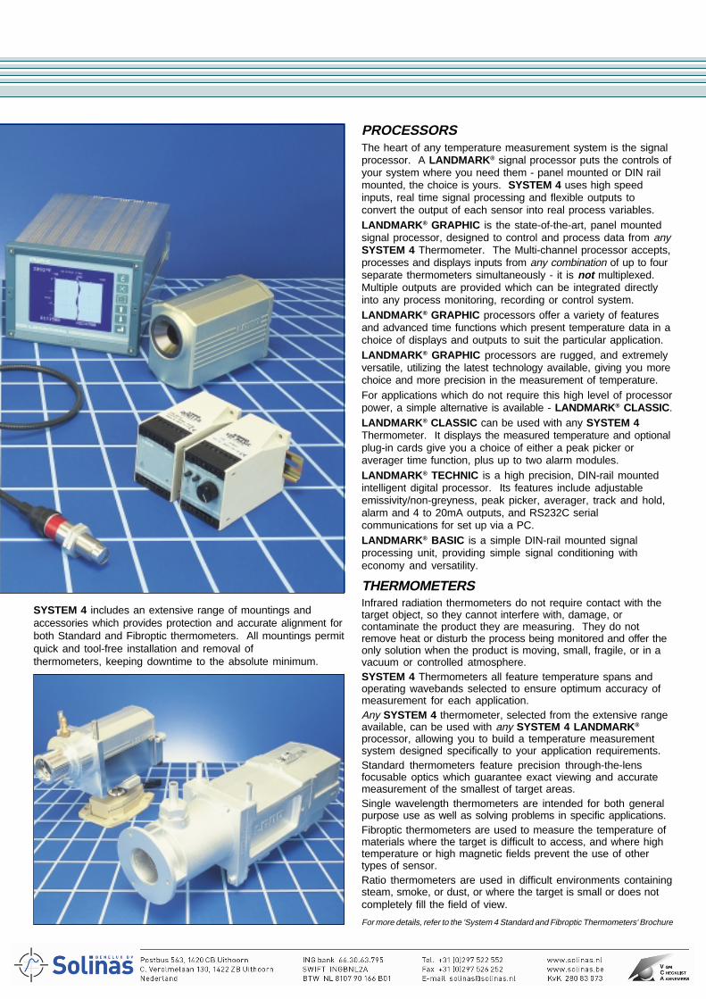
SYSTEM 4 includes an extensive range of mountings andaccessories which provides protection and accurate alignment forboth Standard and Fibroptic thermometers. All mountings permitquick and tool-free installation and removal ofthermometers, keeping downtime to the absolute minimum.
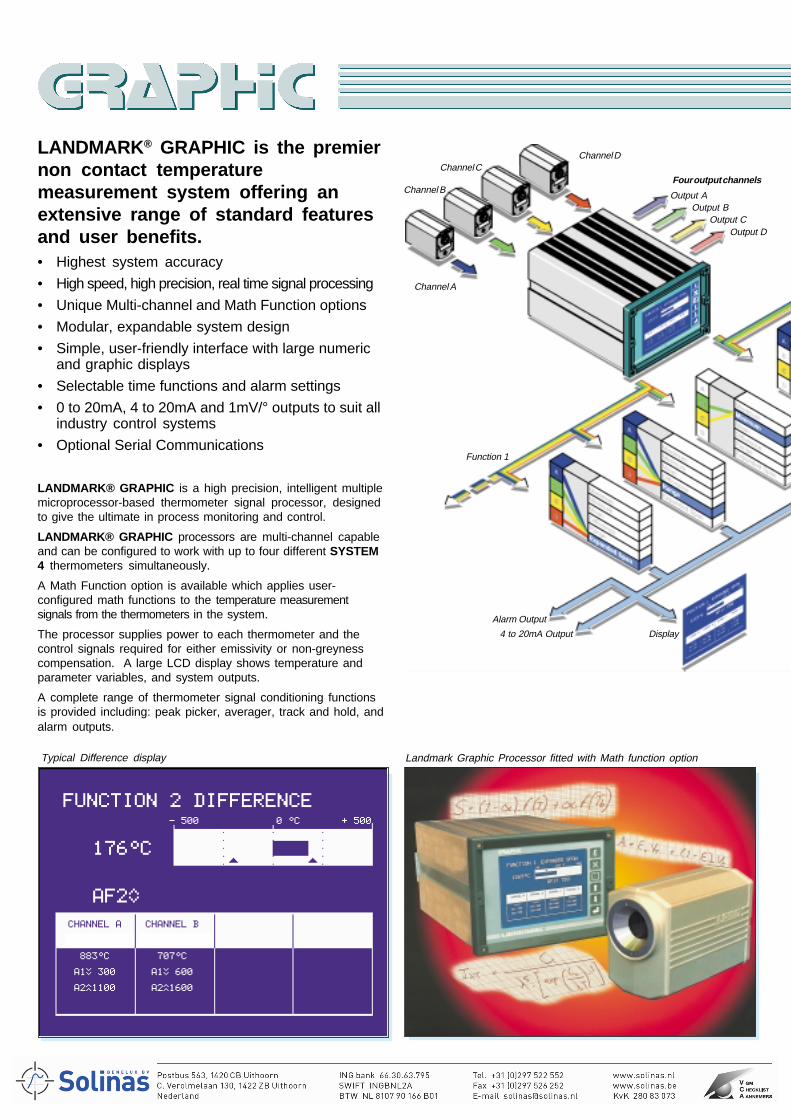
LANDMARK® GRAPHIC is the premiernon contact temperaturemeasurement system offering anextensive range of standard featuresand user benefits.• Highest system accuracy
• High speed, high precision, real time signal processing
• Unique Multi-channel and Math Function options
• Modular, expandable system design
• Simple, user-friendly interface with large numericand graphic displays
• Selectable time functions and alarm settings
• 0 to 20mA, 4 to 20mA and 1mV/° outputs to suit allindustry control systems
• Optional Serial Communications
LANDMARK® GRAPHIC is a high precision, intelligent multiplemicroprocessor-based thermometer signal processor, designedto give the ultimate in process monitoring and control.
LANDMARK® GRAPHIC processors are multi-channel capableand can be configured to work with up to four different SYSTEM4 thermometers simultaneously.
A Math Function option is available which applies user-configured math functions to the temperature measurementsignals from the thermometers in the system.
The processor supplies power to each thermometer and thecontrol signals required for either emissivity or non-greynesscompensation. A large LCD display shows temperature andparameter variables, and system outputs.
A complete range of thermometer signal conditioning functionsis provided including: peak picker, averager, track and hold, andalarm outputs.
Landmark Graphic Processor fitted with Math function option
Channel A
Channel B
Channel CChannel D
Four output channels
Output AOutput B
Output COutput D
Function 1
Display
Alarm Output
4 to 20mA Output
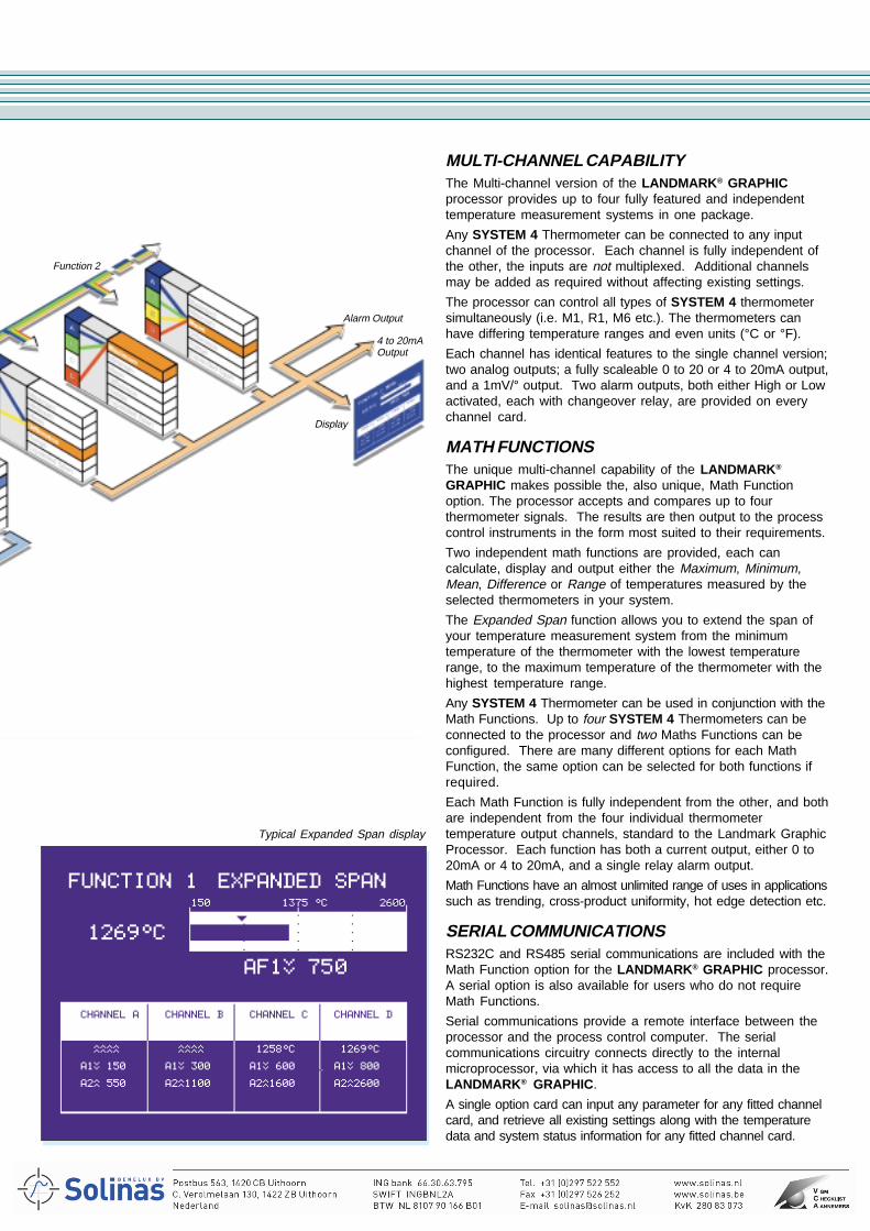
Typical Difference display
MULTI-CHANNEL CAPABILITYThe Multi-channel version of the LANDMARK® GRAPHICprocessor provides up to four fully featured and independenttemperature measurement systems in one package.
Any SYSTEM 4 Thermometer can be connected to any inputchannel of the processor. Each channel is fully independent ofthe other, the inputs are not multiplexed. Additional channelsmay be added as required without affecting existing settings.
The processor can control all types of SYSTEM 4 thermometersimultaneously (i.e. M1, R1, M6 etc.). The thermometers canhave differing temperature ranges and even units (°C or °F).
Each channel has identical features to the single channel version;two analog outputs; a fully scaleable 0 to 20 or 4 to 20mA output,and a 1mV/° output. Two alarm outputs, both either High or Lowactivated, each with changeover relay, are provided on everychannel card.
MATH FUNCTIONSThe unique multi-channel capability of the LANDMARK®
GRAPHIC makes possible the, also unique, Math Functionoption. The processor accepts and compares up to fourthermometer signals. The results are then output to the processcontrol instruments in the form most suited to their requirements.
Two independent math functions are provided, each cancalculate, display and output either the Maximum, Minimum,Mean, Difference or Range of temperatures measured by theselected thermometers in your system.
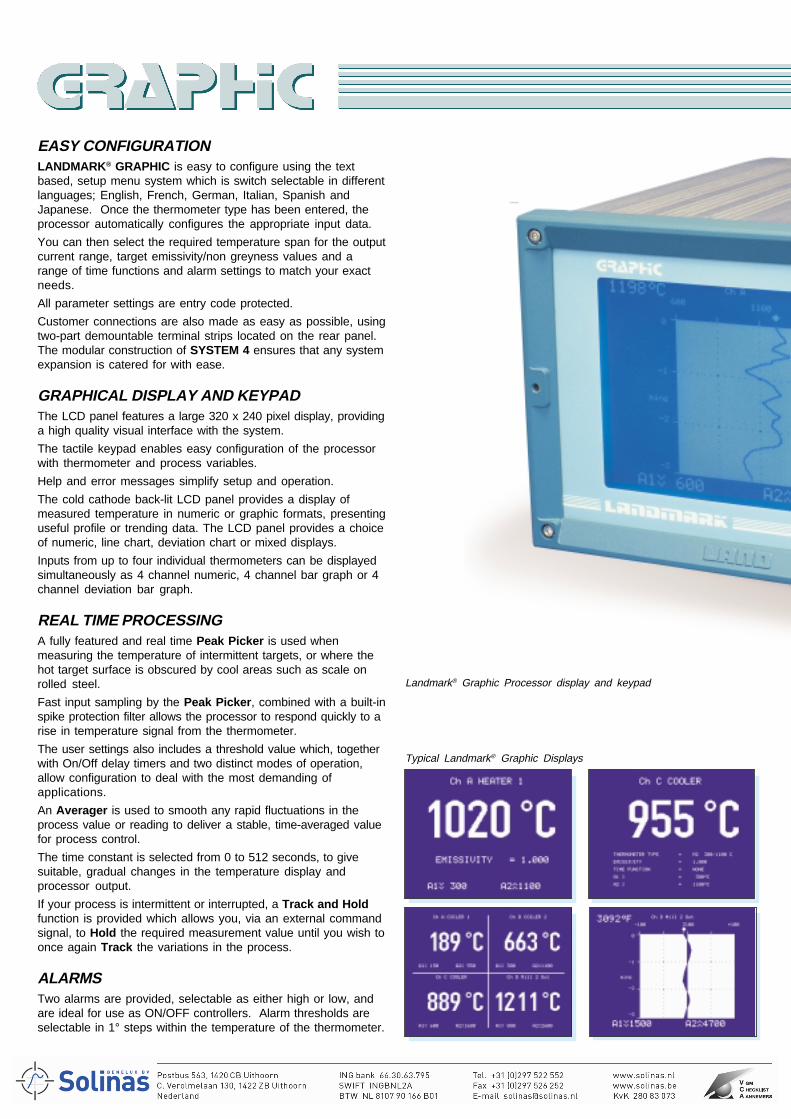
The Expanded Span function allows you to extend the span ofyour temperature measurement system from the minimumtemperature of the thermometer with the lowest temperaturerange, to the maximum temperature of the thermometer with thehighest temperature range.
Any SYSTEM 4 Thermometer can be used in conjunction with theMath Functions. Up to four SYSTEM 4 Thermometers can beconnected to the processor and two Maths Functions can beconfigured. There are many different options for each MathFunction, the same option can be selected for both functions ifrequired.
Each Math Function is fully independent from the other, and bothare independent from the four individual thermometertemperature output channels, standard to the Landmark GraphicProcessor. Each function has both a current output, either 0 to20mA or 4 to 20mA, and a single relay alarm output.
Math Functions have an almost unlimited range of uses in applicationssuch as trending, cross-product uniformity, hot edge detection etc.
SERIAL COMMUNICATIONSRS232C and RS485 serial communications are included with theMath Function option for the LANDMARK® GRAPHIC processor.A serial option is also available for users who do not requireMath Functions.
Serial communications provide a remote interface between theprocessor and the process control computer. The serialcommunications circuitry connects directly to the internalmicroprocessor, via which it has access to all the data in theLANDMARK® GRAPHIC.
A single option card can input any parameter for any fitted channelcard, and retrieve all existing settings along with the temperaturedata and system status information for any fitted channel card.
Typical Expanded Span display
Function 2
Alarm Output
4 to 20mAOutput
Display
EASY CONFIGURATIONLANDMARK® GRAPHIC is easy to configure using the textbased, setup menu system which is switch selectable in differentlanguages; English, French, German, Italian, Spanish andJapanese. Once the thermometer type has been entered, theprocessor automatically configures the appropriate input data.
You can then select the required temperature span for the outputcurrent range, target emissivity/non greyness values and arange of time functions and alarm settings to match your exactneeds.
All parameter settings are entry code protected.
Customer connections are also made as easy as possible, usingtwo-part demountable terminal strips located on the rear panel.The modular construction of SYSTEM 4 ensures that any systemexpansion is catered for with ease.
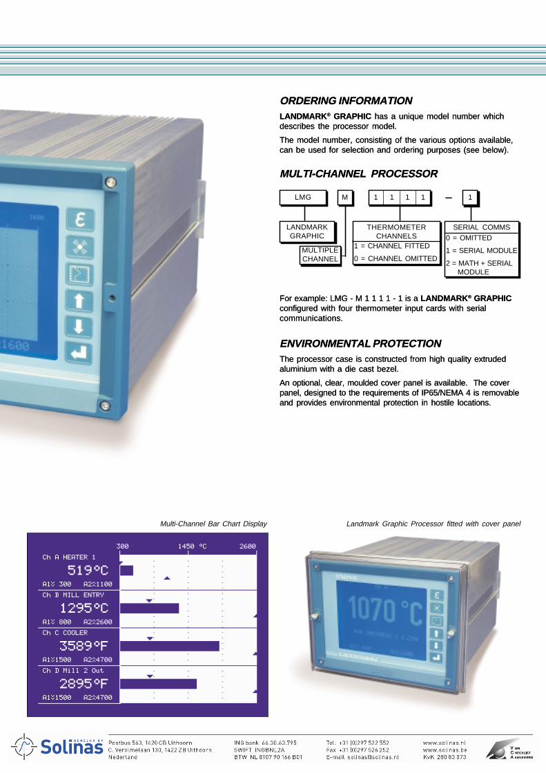
GRAPHICAL DISPLAY AND KEYPADThe LCD panel features a large 320 x 240 pixel display, providinga high quality visual interface with the system.
The tactile keypad enables easy configuration of the processorwith thermometer and process variables.
Help and error messages simplify setup and operation.
The cold cathode back-lit LCD panel provides a display ofmeasured temperature in numeric or graphic formats, presentinguseful profile or trending data. The LCD panel provides a choiceof numeric, line chart, deviation chart or mixed displays.
Inputs from up to four individual thermometers can be displayedsimultaneously as 4 channel numeric, 4 channel bar graph or 4channel deviation bar graph.
REAL TIME PROCESSINGA fully featured and real time Peak Picker is used whenmeasuring the temperature of intermittent targets, or where thehot target surface is obscured by cool areas such as scale onrolled steel.
Fast input sampling by the Peak Picker, combined with a built-inspike protection filter allows the processor to respond quickly to arise in temperature signal from the thermometer.
The user settings also includes a threshold value which, togetherwith On/Off delay timers and two distinct modes of operation,allow configuration to deal with the most demanding ofapplications.
An Averager is used to smooth any rapid fluctuations in theprocess value or reading to deliver a stable, time-averaged valuefor process control.
The time constant is selected from 0 to 512 seconds, to givesuitable, gradual changes in the temperature display andprocessor output.
If your process is intermittent or interrupted, a Track and Holdfunction is provided which allows you, via an external commandsignal, to Hold the required measurement value until you wish toonce again Track the variations in the process.
ALARMSTwo alarms are provided, selectable as either high or low, andare ideal for use as ON/OFF controllers. Alarm thresholds areselectable in 1° steps within the temperature of the thermometer.
Landmark® Graphic Processor display and keypad
Typical Landmark® Graphic Displays
For example: LMG - M 1 1 1 1 - 1 is a LANDMARK® GRAPHICconfigured with four thermometer input cards with serialcommunications.
ENVIRONMENTAL PROTECTIONThe processor case is constructed from high quality extrudedaluminium with a die cast bezel.
An optional, clear, moulded cover panel is available. The coverpanel, designed to the requirements of IP65/NEMA 4 is removableand provides environmental protection in hostile locations.
MULTIPLECHANNEL
M 1 1 1 1 1
THERMOMETERCHANNELS
1 = CHANNEL FITTED
0 = CHANNEL OMITTED
SERIAL COMMS0 = OMITTED
1 = SERIAL MODULE
2 = MATH + SERIALMODULE
ORDERING INFORMATIONLANDMARK® GRAPHIC has a unique model number whichdescribes the processor model.
The model number, consisting of the various options available,can be used for selection and ordering purposes (see below).
MULTI-CHANNEL PROCESSOR
LMG
LANDMARKGRAPHIC
Multi-Channel Bar Chart Display Landmark Graphic Processor fitted with cover panel
For example: LMG - M 1 1 1 1 - 1 is a LANDMARK® GRAPHICconfigured with four thermometer input cards with serialcommunications.
ENVIRONMENTAL PROTECTIONThe processor case is constructed from high quality extrudedaluminium with a die cast bezel.
An optional, clear, moulded cover panel is available. The coverpanel, designed to the requirements of IP65/NEMA 4 is removableand provides environmental protection in hostile locations.
MULTIPLECHANNEL
M 1 1 1 1 1
THERMOMETERCHANNELS
1 = CHANNEL FITTED
0 = CHANNEL OMITTED
SERIAL COMMS0 = OMITTED
1 = SERIAL MODULE
2 = MATH + SERIALMODULE
ORDERING INFORMATIONLANDMARK® GRAPHIC has a unique model number whichdescribes the processor model.
The model number, consisting of the various options available,can be used for selection and ordering purposes (see below).
MULTI-CHANNEL PROCESSOR
LMG
LANDMARKGRAPHIC
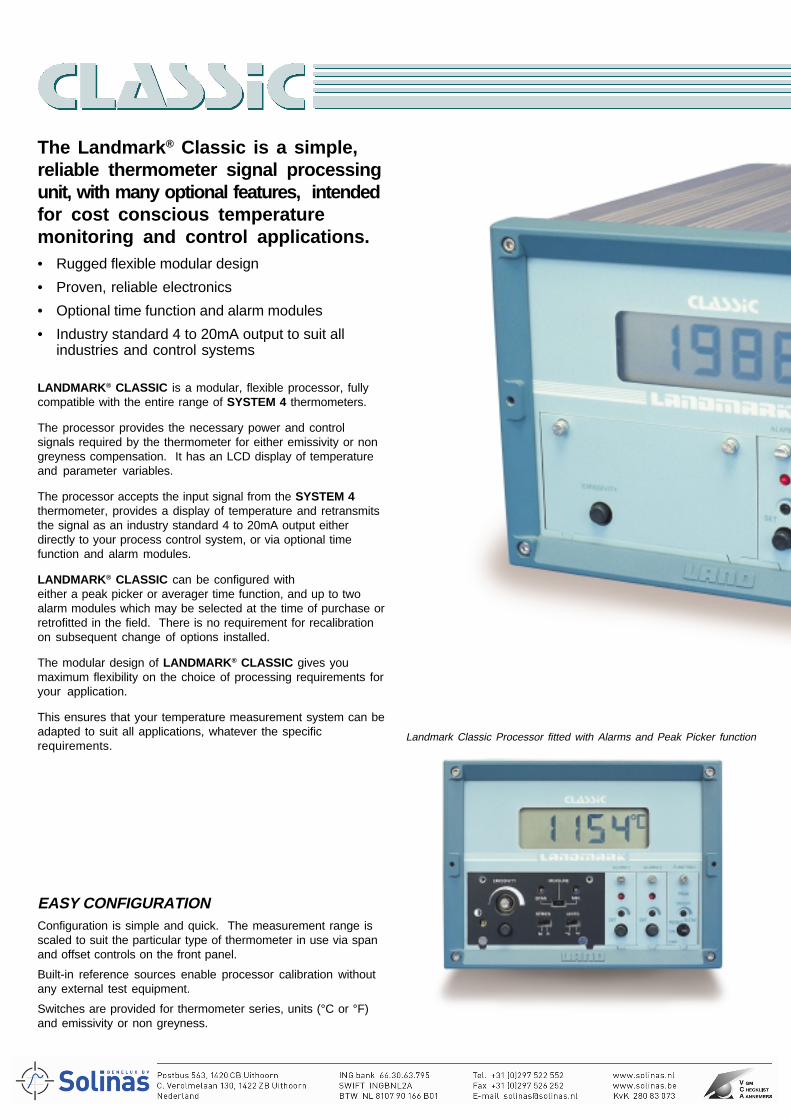
The Landmark® Classic is a simple,reliable thermometer signal processingunit, with many optional features, intendedfor cost conscious temperaturemonitoring and control applications.• Rugged flexible modular design
• Proven, reliable electronics
• Optional time function and alarm modules
• Industry standard 4 to 20mA output to suit allindustries and control systems
LANDMARK® CLASSIC is a modular, flexible processor, fullycompatible with the entire range of SYSTEM 4 thermometers.
The processor provides the necessary power and controlsignals required by the thermometer for either emissivity or nongreyness compensation. It has an LCD display of temperatureand parameter variables.
The processor accepts the input signal from the SYSTEM 4thermometer, provides a display of temperature and retransmitsthe signal as an industry standard 4 to 20mA output eitherdirectly to your process control system, or via optional timefunction and alarm modules.
LANDMARK® CLASSIC can be configured witheither a peak picker or averager time function, and up to twoalarm modules which may be selected at the time of purchase orretrofitted in the field. There is no requirement for recalibrationon subsequent change of options installed.
The modular design of LANDMARK® CLASSIC gives youmaximum flexibility on the choice of processing requirements foryour application.
This ensures that your temperature measurement system can beadapted to suit all applications, whatever the specificrequirements.
EASY CONFIGURATIONConfiguration is simple and quick. The measurement range isscaled to suit the particular type of thermometer in use via spanand offset controls on the front panel.
Built-in reference sources enable processor calibration withoutany external test equipment.
Switches are provided for thermometer series, units (°C or °F)and emissivity or non greyness.
Landmark Classic Processor fitted with Alarms and Peak Picker function
Landmark Classic Processor fitted with cover panel
DISPLAYThe large, easy to read LCD panel provides a continuousdisplay of measured temperature, together with over and underrange indications.
Alarm and emissivity or non-greyness settings are displayed atthe press of a button.
REAL TIME PROCESSINGA fully featured and real time Peak Picker is used whenmeasuring the temperature of intermittent targets, or where thehot target surface is obscured by cool areas such as scale onrolled steel.
Fast input sampling by the Peak Picker, combined with a built-inspike protection filter allows the processor to respond quickly toa rise in temperature signal from the thermometer.
The Peak Picker has a user adjustable decay rate and bothmanual and remote reset controls, giving flexibility to deal withthe most demanding of applications.
An Averager is used to smooth any rapid fluctuations in theprocess value or reading to deliver a stable, time-averagedvalue for process control.
The time constant is selected from 0 to 512 seconds, to givesuitable, gradual changes in the temperature display andprocessor output.
ALARMSTwo alarms are provided, selectable as either high or low, andare ideal for use as ON/OFF controllers. Alarm thresholds areadjustable in 1° steps within the temperature of the thermometer.
ENVIRONMENTAL PROTECTIONThe processor case is constructed from high quality extrudedaluminium with a die cast bezel. An optional, clear, mouldeddoor panel is available. The door panel, designed to therequirements of IP65/NEMA 4, is removable and providesenvironmental protection in hostile locations, as well as adegree of tamper proofing.
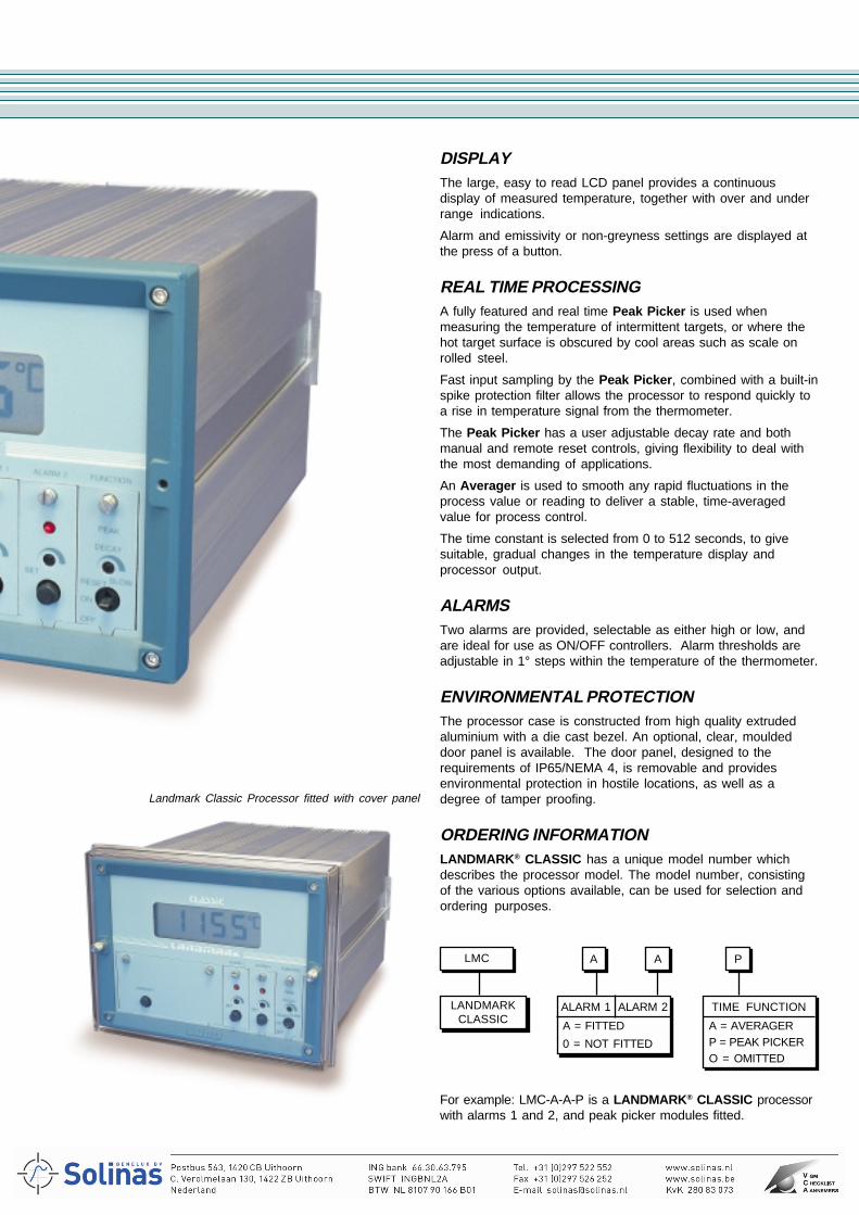
ORDERING INFORMATIONLANDMARK® CLASSIC has a unique model number whichdescribes the processor model. The model number, consistingof the various options available, can be used for selection andordering purposes.
A A P
ALARM 1 ALARM 2 TIME FUNCTION
A = FITTED
0 = NOT FITTED
A = AVERAGERP = PEAK PICKERO = OMITTED
For example: LMC-A-A-P is a LANDMARK® CLASSIC processorwith alarms 1 and 2, and peak picker modules fitted.
LMC
LANDMARKCLASSIC
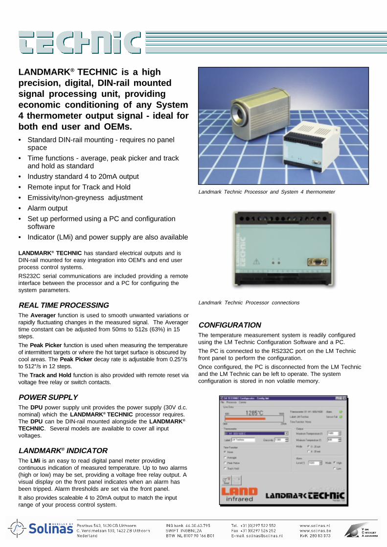
LANDMARK® TECHNIC is a highprecision, digital, DIN-rail mountedsignal processing unit, providingeconomic conditioning of any System4 thermometer output signal - ideal forboth end user and OEMs.• Standard DIN-rail mounting - requires no panel
space
• Time functions - average, peak picker and trackand hold as standard
• Industry standard 4 to 20mA output
• Remote input for Track and Hold
• Emissivity/non-greyness adjustment
• Alarm output
• Set up performed using a PC and configurationsoftware
• Indicator (LMi) and power supply are also available
LANDMARK® TECHNIC has standard electrical outputs and isDIN-rail mounted for easy integration into OEM's and end userprocess control systems.
RS232C serial communications are included providing a remoteinterface between the processor and a PC for configuring thesystem parameters.
REAL TIME PROCESSINGThe Averager function is used to smooth unwanted variations orrapidly fluctuating changes in the measured signal. The Averagertime constant can be adjusted from 50ms to 512s (63%) in 15steps.
The Peak Picker function is used when measuring the temperatureof intermittent targets or where the hot target surface is obscured bycool areas. The Peak Picker decay rate is adjustable from 0.25°/sto 512°/s in 12 steps.
The Track and Hold function is also provided with remote reset viavoltage free relay or switch contacts.
POWER SUPPLYThe DPU power supply unit provides the power supply (30V d.c.nominal) which the LANDMARK® TECHNIC processor requires.The DPU can be DIN-rail mounted alongside the LANDMARK®
TECHNIC. Several models are available to cover all inputvoltages.
LANDMARK® INDICATORThe LMi is an easy to read digital panel meter providingcontinuous indication of measured temperature. Up to two alarms(high or low) may be set, providing a voltage free relay output. Avisual display on the front panel indicates when an alarm hasbeen tripped. Alarm thresholds are set via the front panel.
It also provides scaleable 4 to 20mA output to match the inputrange of your process control system.
Landmark Technic Processor and System 4 thermometer
Landmark Technic Processor connections
CONFIGURATIONThe temperature measurement system is readily configuredusing the LM Technic Configuration Software and a PC.
The PC is connected to the RS232C port on the LM Technicfront panel to perform the configuration.
Once configured, the PC is disconnected from the LM Technicand the LM Technic can be left to operate. The systemconfiguration is stored in non volatile memory.
Landmark Basic Processor controls
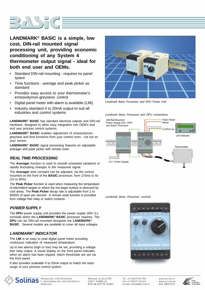
LANDMARK® BASIC is a simple, lowcost, DIN-rail mounted signalprocessing unit, providing economicconditioning of any System 4thermometer output signal - ideal forboth end user and OEMs.• Standard DIN-rail mounting - requires no panel
space
• Time functions - average and peak picker asstandard
• Provides easy access to your thermometer'semissivity/non-greyness control
• Digital panel meter with alarm is available (LMi)
• Industry standard 4 to 20mA output to suit allindustries and control systems
LANDMARK® BASIC has standard electrical outputs and DIN-railhardware, designed to allow easy integration into OEM's andend user process control systems.
LANDMARK® BASIC enables adjustment of emissivity/non-greyness and time functions from your control room - not out onyour sensor.
LANDMARK® BASIC signal processing features an adjustableaverager and peak picker with remote reset.
REAL TIME PROCESSINGThe Averager function is used to smooth unwanted variations orrapidly fluctuating changes in the measured signal.
The Averager time constant can be adjusted, via the controlmounted on the front of the BASIC processor, from 175ms to 4s(10 to 90%).
The Peak Picker function is used when measuring the temperatureof intermittent targets or where the hot target surface is obscured bycool areas. The Peak Picker decay rate is adjustable from 1 to5000% of span per second. A remote reset function is providedfrom voltage free relay or switch contacts.
POWER SUPPLYThe DPU power supply unit provides the power supply (30V d.c.nominal) which the LANDMARK® BASIC processor requires. TheDPU can be DIN-rail mounted alongside the LANDMARK®
BASIC. Several models are available to cover all input voltages.
LANDMARK® INDICATORThe LMi is an easy to read digital panel meter providingcontinuous indication of measured temperature.
Up to two alarms (high or low) may be set, providing a voltagefree relay output. A visual display on the front panel indicateswhen an alarm has been tripped. Alarm thresholds are set viathe front panel.
It also provides scaleable 4 to 20mA output to match the inputrange of your process control system.
Landmark Basic Processor and DPU Power Unit
Landmark Basic Processor and DPU connections
DIN Rail MountedPower Supply Unit - DPUand Basic Processor
Peak PickerReset
4-20mA out
LMi Indicator
Thermometer
A.C. Power Supply
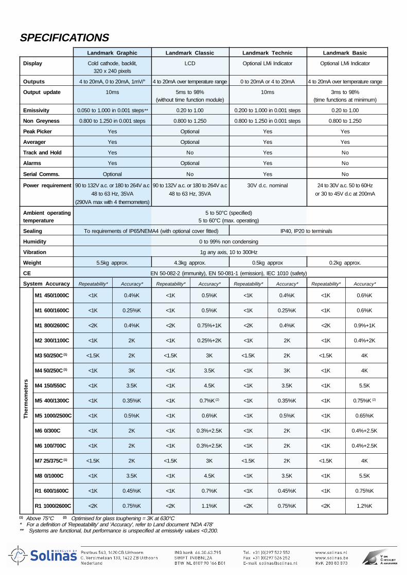
(1) Above 75°C (2) Optimised for glass toughening = 3K at 630°C* For a definition of 'Repeatability' and 'Accuracy', refer to Land document 'NDA 478'** Systems are functional, but performance is unspecified at emissivity values <0.200.
Th
erm
om
eter
s
Landmark Graphic Landmark Classic Landmark Technic Landmark Basic
Display Cold cathode, backlit, LCD Optional LMi Indicator Optional LMi Indicator320 x 240 pixels
Outputs 4 to 20mA, 0 to 20mA, 1mV/° 4 to 20mA over temperature range 0 to 20mA or 4 to 20mA 4 to 20mA over temperature range
Output update 10ms 5ms to 98% 10ms 3ms to 98%(without time function module) (time functions at minimum)
Emissivity 0.050 to 1.000 in 0.001 steps** 0.20 to 1.00 0.200 to 1.000 in 0.001 steps 0.20 to 1.00
Non Greyness 0.800 to 1.250 in 0.001 steps 0.800 to 1.250 0.800 to 1.250 in 0.001 steps 0.800 to 1.250
Peak Picker Yes Optional Yes Yes
Averager Yes Optional Yes Yes
Track and Hold Yes No Yes No
Alarms Yes Optional Yes No
Serial Comms. Optional No Yes No
Power requirement 90 to 132V a.c. or 180 to 264V a.c 90 to 132V a.c. or 180 to 264V a.c 30V d.c. nominal 24 to 30V a.c. 50 to 60Hz
48 to 63 Hz, 35VA 48 to 63 Hz, 35VA or 30 to 45V d.c at 200mA
(290VA max with 4 thermometers)
Ambient operating 5 to 50°C (specified)temperature 5 to 60°C (max. operating)
Sealing To requirements of IP65/NEMA4 (with optional cover fitted) IP40, IP20 to terminals
Humidity 0 to 99% non condensing
Vibration 1g any axis, 10 to 300Hz
Weight 5.5kg approx. 4.3kg approx. 0.5kg approx 0.2kg approx.
CE EN 50-082-2 (immunity), EN 50-081-1 (emission), IEC 1010 (safety)
System Accuracy Repeatability* Accuracy* Repeatability* Accuracy* Repeatability* Accuracy* Repeatability* Accuracy*
M1 450/1000C <1K 0.4%K <1K 0.5%K <1K 0.4%K <1K 0.6%K
M1 600/1600C <1K 0.25%K <1K 0.5%K <1K 0.25%K <1K 0.6%K
M1 800/2600C <2K 0.4%K <2K 0.75%+1K <2K 0.4%K <2K 0.9%+1K
M2 300/1100C <1K 2K <1K 0.25%+2K <1K 2K <1K 0.4%+2K
M3 50/250C (1) <1.5K 2K <1.5K 3K <1.5K 2K <1.5K 4K
M4 50/250C (1) <1K 3K <1K 3.5K <1K 3K <1K 4K
M4 150/550C <1K 3.5K <1K 4.5K <1K 3.5K <1K 5.5K
M5 400/1300C <1K 0.35%K <1K 0.7%K (2) <1K 0.35%K <1K 0.75%K (2)
M5 1000/2500C <1K 0.5%K <1K 0.6%K <1K 0.5%K <1K 0.65%K
M6 0/300C <1K 2K <1K 0.3%+2.5K <1K 2K <1K 0.4%+2.5K
M6 100/700C <1K 2K <1K 0.3%+2.5K <1K 2K <1K 0.4%+2.5K
M7 25/375C (1) <1.5K 2K <1.5K 3K <1.5K 2K <1.5K 4K
M8 0/1000C <1K 3.5K <1K 4.5K <1K 3.5K <1K 5.5K
R1 600/1600C <1K 0.45%K <1K 0.7%K <1K 0.45%K <1K 0.75%K
R1 1000/2600C <2K 0.75%K <2K 1.1%K <2K 0.75%K <2K 1.2%K
SPECIFICATIONS
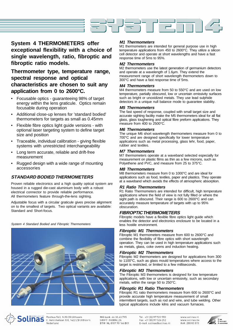
System 4 THERMOMETERS offerexceptional flexibility with a choice ofsingle wavelength, ratio, fibroptic andfibroptic ratio models.
Thermometer type, temperature range,spectral response and opticalcharacteristics are chosen to suit anyapplication from 0 to 2600°C.• Focusable optics - guaranteeing 98% of target
energy within the lens graticule. Optics remainfocusable during operation
• Additional close-up lenses for 'standard bodied'thermometers for targets as small as 0.45mm
• Flexible fibre optics light guide versions - withoptional laser targeting system to define targetsize and position
• Traceable, individual calibration - giving flexiblesystems with unrestricted interchangeability
• Long term accurate, reliable and drift-freemeasurement
• Rugged design with a wide range of mountingaccessories
STANDARD BODIED THERMOMETERSProven reliable electronics and a high quality optical system arehoused in a rugged die-cast aluminium body with a robustelectrical connector to provide reliable performance.All thermometers feature through-the-lens sighting.
Adjustable focus with a circular graticule gives precise alignmenton to the smallest of targets. Two optical variants are available:Standard and Short-focus.
M1 ThermometersM1 thermometers are intended for general purpose use in hightemperature applications from 450 to 2600°C. They utilize a siliconcell detector and operate at short wavelengths and have a fastresponse time of 5ms to 95%.
M2 ThermometersM2 thermometers use the latest generation of germanium detectorsand operate at a wavelength of 1.6µm. They extend themeasurement range of short wavelength thermometers down to300°C and have a fast response time of 5ms.
M4 ThermometersM4 thermometers measure from 50 to 550°C and are used on lowtemperature, partially obscured, low or uncertain emissivity surfacessuch as bright or unoxidized metals. They use lead sulphidedetectors in a unique null balance mode to guarantee stability.
M5 ThermometersThe fast speed of response, coupled with small target size andaccurate sighting facility make the M5 thermometers ideal for all flatglass, glass toughening and optical fibre preform applications. Theymeasure from 400 to 2500°C.
M6 ThermometersThe unique M6 short wavelength thermometers measure from 0 to700°C and are designed specifically for lower temperatureapplications such as metal processing, glass lehr, food, paper,rubber and textiles.
M7 ThermometersM7 thermometers operate at a waveband selected especially formeasurement on plastic films as thin as a few microns, such asPolyethene and PVC, and measure from 25 to 375°C.
M8 ThermometersM8 thermometers measure from 0 to 1000°C and are ideal forapplications such as food, textiles, paper and plastics. They operateat a waveband which avoids the effects of atmospheric absorption.
R1 Ratio ThermometersR1 Ratio Thermometers are intended for difficult, high temperatureapplications where the field of view is not fully filled or where thesight path is obscured. Their range is 600 to 2600°C and canaccurately measure temperature of targets with up to 95%obscuration.
FIBROPTIC THERMOMETERSFibroptic models have a flexible fibre optics light guide whichenables the detector and electronics enclosure to be located in aless hostile environment.
Fibroptic M1 ThermometersFibroptic M1 thermometers measure from 600 to 2600°C andcombine the flexibility of fibre optics with short wavelengthoperation. They can be used in high temperature applications suchas metals, glass, coke ovens and induction heating.
Fibroptic M2 ThermometersFibroptic M2 thermometers are designed for applications from 300to 1100°C, such as glass mould temperatures where access to thetarget is restricted, or limited to a few milliseconds.
Fibroptic M3 ThermometersThe Fibroptic M3 thermometers is designed for low temperatureapplications, with low or uncertain emissivity, such as secondarymetals, within the range 50 to 250°C.
Fibroptic R1 Ratio ThermometersFibroptic R1 ratio thermometers measure from 600 to 2600°C andprovide accurate high temperature measurement of smallintermittent targets, such as rod and wire, and tube welding. Othertypical applications include kilns and vacuum furnaces.
System 4 Standard Bodied and Fibroptic Thermometers
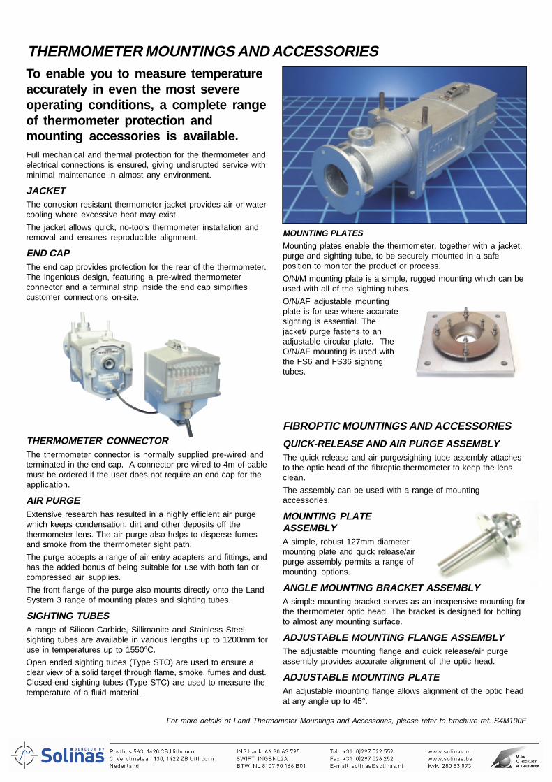
To enable you to measure temperatureaccurately in even the most severeoperating conditions, a complete rangeof thermometer protection andmounting accessories is available.Full mechanical and thermal protection for the thermometer andelectrical connections is ensured, giving undisrupted service withminimal maintenance in almost any environment.
JACKETThe corrosion resistant thermometer jacket provides air or watercooling where excessive heat may exist.
The jacket allows quick, no-tools thermometer installation andremoval and ensures reproducible alignment.
END CAPThe end cap provides protection for the rear of the thermometer.The ingenious design, featuring a pre-wired thermometerconnector and a terminal strip inside the end cap simplifiescustomer connections on-site.
MOUNTING PLATESMounting plates enable the thermometer, together with a jacket,purge and sighting tube, to be securely mounted in a safeposition to monitor the product or process.
O/N/M mounting plate is a simple, rugged mounting which can beused with all of the sighting tubes.
O/N/AF adjustable mountingplate is for use where accuratesighting is essential. Thejacket/ purge fastens to anadjustable circular plate. TheO/N/AF mounting is used withthe FS6 and FS36 sightingtubes.
FIBROPTIC MOUNTINGS AND ACCESSORIES
QUICK-RELEASE AND AIR PURGE ASSEMBLYThe quick release and air purge/sighting tube assembly attachesto the optic head of the fibroptic thermometer to keep the lensclean.
The assembly can be used with a range of mountingaccessories.
MOUNTING PLATEASSEMBLYA simple, robust 127mm diametermounting plate and quick release/airpurge assembly permits a range ofmounting options.
ANGLE MOUNTING BRACKET ASSEMBLYA simple mounting bracket serves as an inexpensive mounting forthe thermometer optic head. The bracket is designed for boltingto almost any mounting surface.
ADJUSTABLE MOUNTING FLANGE ASSEMBLYThe adjustable mounting flange and quick release/air purgeassembly provides accurate alignment of the optic head.
ADJUSTABLE MOUNTING PLATEAn adjustable mounting flange allows alignment of the optic headat any angle up to 45°.
THERMOMETER CONNECTORThe thermometer connector is normally supplied pre-wired andterminated in the end cap. A connector pre-wired to 4m of cablemust be ordered if the user does not require an end cap for theapplication.
AIR PURGEExtensive research has resulted in a highly efficient air purgewhich keeps condensation, dirt and other deposits off thethermometer lens. The air purge also helps to disperse fumesand smoke from the thermometer sight path.
The purge accepts a range of air entry adapters and fittings, andhas the added bonus of being suitable for use with both fan orcompressed air supplies.
The front flange of the purge also mounts directly onto the LandSystem 3 range of mounting plates and sighting tubes.
SIGHTING TUBESA range of Silicon Carbide, Sillimanite and Stainless Steelsighting tubes are available in various lengths up to 1200mm foruse in temperatures up to 1550°C.
Open ended sighting tubes (Type STO) are used to ensure aclear view of a solid target through flame, smoke, fumes and dust.Closed-end sighting tubes (Type STC) are used to measure thetemperature of a fluid material.
For more details of Land Thermometer Mountings and Accessories, please refer to brochure ref. S4M100E
THERMOMETER MOUNTINGS AND ACCESSORIES
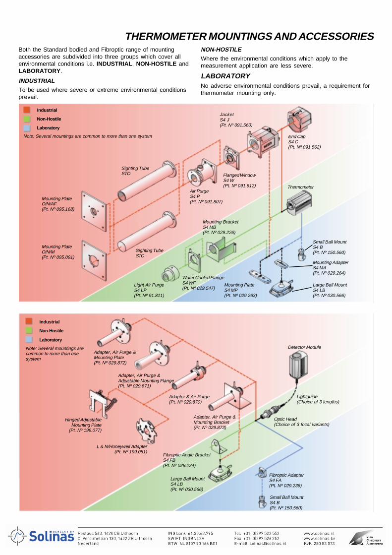
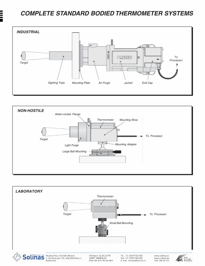
NON-HOSTILEWhere the environmental conditions which apply to themeasurement application are less severe.
LABORATORYNo adverse environmental conditions prevail, a requirement forthermometer mounting only.
Both the Standard bodied and Fibroptic range of mountingaccessories are subdivided into three groups which cover allenvironmental conditions i.e. INDUSTRIAL, NON-HOSTILE andLABORATORY.
INDUSTRIALTo be used where severe or extreme environmental conditionsprevail.
THERMOMETER MOUNTINGS AND ACCESSORIES
Note: Several mountings arecommon to more than onesystem
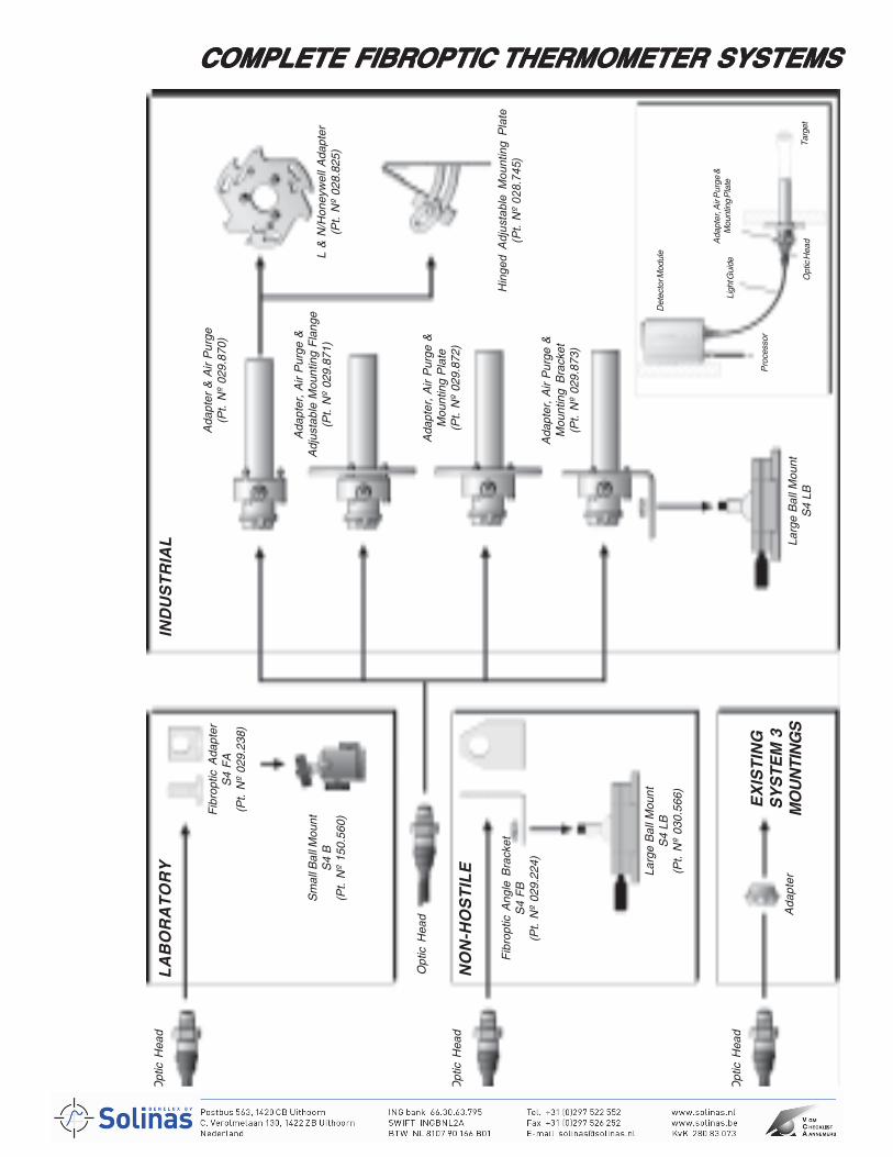
Adapter, Air Purge &Mounting Plate(Pt. Nº 029.872)
Adapter, Air Purge &Adjustable Mounting Flange(Pt. Nº 029.871)
Adapter & Air Purge(Pt. Nº 029.870)
Adapter, Air Purge &Mounting Bracket(Pt. Nº 029.873)
Hinged AdjustableMounting Plate
(Pt. Nº 199.077)
L & N/Honeywell Adapter(Pt. Nº 199.051)
Large Ball MountS4 LB(Pt. Nº 030.566)
Fibroptic Angle BracketS4 FB(Pt. Nº 029.224)
Fibroptic AdapterS4 FA(Pt. Nº 029.238)
Small Ball MountS4 B(Pt. Nº 150.560)
Optic Head(Choice of 3 focal variants)
Lightguide(Choice of 3 lengths)
Detector Module
Note: Several mountings are common to more than one system
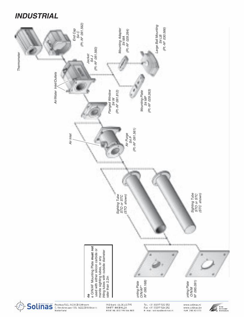
Mounting PlateO/N/AF(Pt. Nº 095.168)
Sighting TubeSTO
Air PurgeS4 P(Pt. Nº 091.807)
Flanged WindowS4 W(Pt. Nº 091.812)
End CapS4 C(Pt. Nº 091.562)
JacketS4 J(Pt. Nº 091.560)
Thermometer
Mounting PlateO/N/M(Pt. Nº 095.091)
Sighting TubeSTC
Water Cooled FlangeS4 WF(Pt. Nº 029.547)
Light Air PurgeS4 LP(Pt. Nº 91.811)
Mounting BracketS4 MB(Pt. Nº 029.226)
Mounting PlateS4 MP(Pt. Nº 029.263)
Mounting AdapterS4 MA(Pt. Nº 029.264)
Small Ball MountS4 B(Pt. Nº 150.560)
Large Ball MountS4 LB(Pt. Nº 030.566)
Industrial
Non-Hostile
Laboratory
Industrial
Non-Hostile
Laboratory
WORLD LEADERSLAND is the world leader in themanufacture of non contacttemperature measurementsystems, thermal imagers andlinescanners.
WORLDWIDESUPPORT
In addition to the companiesestablished in Europe, USA,Mexico and Japan, LAND isrepresented by distributors inmost of the major industrialcountries throughout the world.
Our customers benefit, on aglobal basis, from practical andexpert advice from fully trainedtechnicians who are aware ofspecific requirements for theircountry and industry.
CALIBRATIONLAND operate an extensivecalibration service. Allcalibrations made are traceableto National Standards.Calibration certificates areavailable from our UKASaccredited calibration laboratory0034.
In the USA a traceablecalibration certificate can beissued complying with theNational Institute of Standardsand Technology (NIST).
A consultancy service is alsoavailable for those companieswho wish to establish their ownin-house calibration facility.
Printed in England Continuous product development may make it necessary to change these details without notice. S4P101E/0303
These products comply with current European directives relating to electromagnetic compatibilityand safety (EMC directive 89/336/EEC; Low voltage directive 73/23/EEC).
The Quality Management System of Land Instruments International Ltd. is approved to BS EN ISO9001:2000for the design and manufacture, stockholding, in-house repair and site servicing of non contact temperaturemeasuring instrumentation. Associated software designed and developed in accordance with TickIT.Calibration certificates are available from our UKAS accredited Calibration Laboratory No. 0034. The Landcalibration laboratory complies with the requirements of the international standard BS EN ISO/IEC 17025.
A
Land Instruments International • Dronfield S18 1DJ • England • Tel: (01246) 417691 • Fax: (01246) 410585Email: [email protected] • Internet: www.landinst.com
Land Instruments International • 10 Friends Lane • Newtown, PA 18940-1804 • U.S.A. • Tel: (215) 504-8000Fax: (215) 504-0879 • Email: [email protected] • Internet: www.landinstruments.net
France Germany ItalyLand Instruments Sarl Land Instruments GmbH Land Instruments SrlTel: (1) 34 62 05 45 • Fax: (1) 30 56 51 12 Tel: 02171/7673-0 • Fax: 02171/7673-9 Tel: 02/99040423 • Fax: 02/99040418Email: [email protected] Email: [email protected] Email: [email protected]
Japan Spain MexicoLand KK Land Instruments International Land Instruments InternationalTel: 06 6330 5153 • Fax: 06 6330 5338 Tel: 91 630 0791 • Fax: 91 630 2918 Tel: 52 55 9171 1466 • Fax: 52 55 9171 1477Email: [email protected] Email: [email protected] Email: [email protected]
abcdefgabc
For more than fifty years LAND have supplied temperature measuring and process imagingsystems to many different industries all over the world. Now the world leader in non contactthermometry, our expert advice and support is never far away.
WORLDWIDE SUPPORT
Expert advice and support is never far away
APPLICATIONSLAND have solved many different temperature measurement problems in a wide variety of industriesfrom food to atomic energy, some of which are list below:
• Iron & Steel • Maintenance • Plastics• Petrochemical • Power & Utilities • Paper• Heat Treatment • Aerospace • Rubber• Minerals • Electronics • Textiles• Glass • Pharmaceuticals • Non-ferrous Metals
For further information or free advice on specific temperature measurement problems within these orany other industry, contact your nearest Land office.
PRODUCT ASSURANCEWhen you specify LAND products you are assured of receiving a completely pretested, calibratedworking product. Each instrument is carefully checked to ensure complete compliance with specificationand is fully guaranteed. LAND was the first manufacturer of infrared instruments to successfully obtainISO 9001 Quality Management System Approval for both design and manufacture of non contactinfrared temperature measuring equipment.
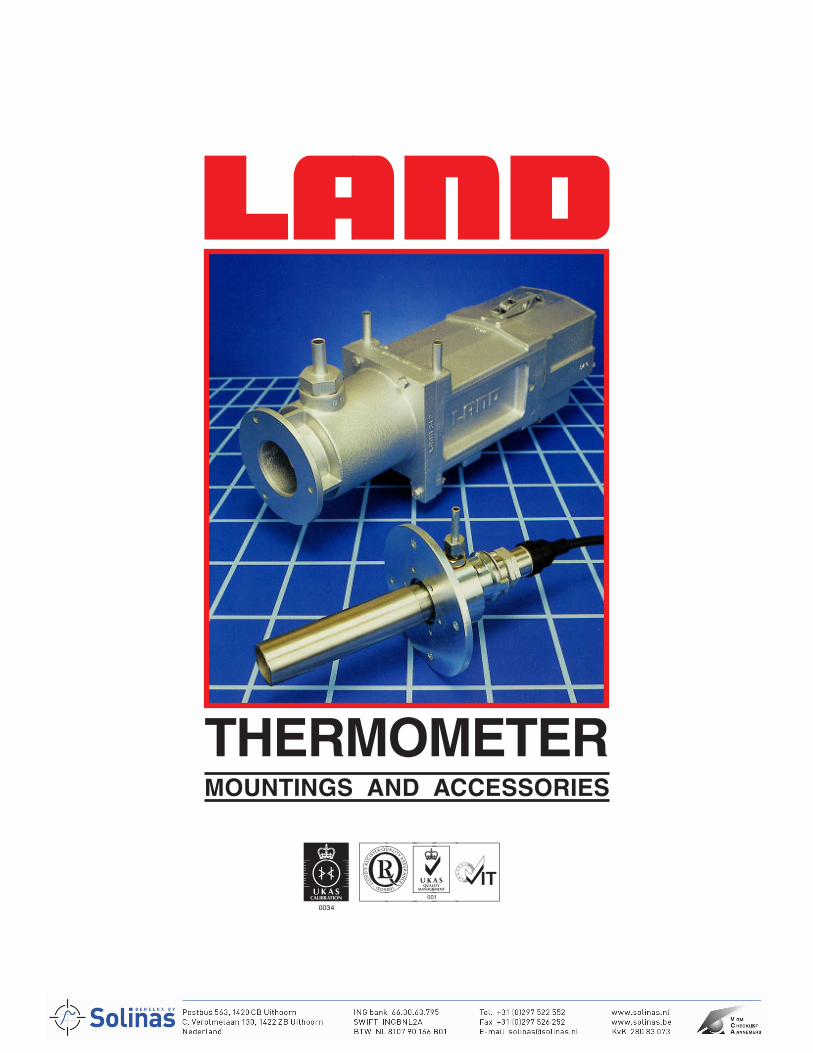
THERMOMETERMOUNTINGS AND ACCESSORIES
abc
abcdefgabc

2
The new Standard Bodied and Fibroptic range of temperature measurement systems from Land Infrared includes acomprehensive range of thermometer mounting and protection accessories to suit any measurement environment. All mountingsand accessories feature quick and tool-free installation and removal. The range of accessories can be sub-divided into threegroups INDUSTRIAL, NON-HOSTILE and LABORATORY. These groups provide a classification which equate to the givenenvironmental conditions.
abc
SELECTING MOUNTINGS AND ACCESSORIESThe following information will help determine which specific mountings and accessories are necessary to maintainmeasurement accuracy and reliability of performance of the thermometer.Cooling Jacket - Standard ThermometersThe thermometer cooling and protection jacket provides benefits where there is a requirement for:• Thermal protection of the thermometer i.e high ambient temperatures• Mechanical protection of the thermometer i.e risk of damage• Full environmental protection of the thermometer i.e water or smoke ingressEnd Cap - Standard ThermometersThe End Cap provides benefits where there is a requirement for:• Full environmental protection of the thermometer electrical connections i.e water ingressAir PurgeThe Air Purge clears dust, steam and smoke from the thermometer sight path to ensure accurate temperature measurement.An Air Purge is required to:• Clear the sight path• Prevent build-up of debris on the thermometer lens• Protect the lens from flame or gas impingementMounting Bracket/Plate/AdapterThe range of brackets, plates and adapters are used where there is a need for:• Fixed, robust installation• Thermal protection• Mechanical protection• Angular adjustment (accurate sighting)Sighting TubesSighting Tubes are used for:• Viewing the target through flame, smoke, fumes etc.
INDUSTRIAL For full details of Standard Body INDUSTRIAL Mountings and Accessories refer to pages 4 - 7.For Fibroptic INDUSTRIAL Mountings and Accessories, refer to pages 12 and13.To be used where severe or extreme environmental conditions prevail.• High or low ambient temperatures• Smoke, steam, fumes present in the atmosphere i.e. requirement for thermometer purge• Exposure to exceptional environmental conditions i.e. inside a furnace• Potential damage from personnel or other equipmentNON-HOSTILE For full details of Standard Body NON-HOSTILE Mountings and Accessories refer to pages 8 and 9.For Fibroptic NON-HOSTILE Mountings and Accessories refer to page 14.Where the environmental conditions which apply to the measurement application are less severe i.e. Non-Hostile.• Room temperature operating conditions i.e. none or minimal requirement for thermometer cooling• Absence of large amounts of smoke, steam, fumes etc i.e potential for air purging to maintain accuracy of reading only• No unusual environmental conditions• No possibility of damage from personnel or other equipment i.e no requirement for heavy-duty mountingsLABORATORY For full details of Standard Body LABORATORY Mountings and Accessories refer to page 10.For Fibroptic LABORATORY Mountings and Accessories refer to pages 14 and 15.No adverse environmental conditions prevail, a requirement for thermometer mounting only.AIR SUPPLY SYSTEMS For full details of AIR SUPPLY SYSTEMS refer to page 15.Note: Pt. No. - Land Part Number code - please specify when enquiring or ordering.All dimensions are given in inches.
3
COMPLETE STANDARD BODIED THERMOMETER SYSTEMS
Target
Light Purge Mounting Adapter
Large Ball Mounting
To Processor
Mounting ShoeThermometer
Water-cooled Flange
Target
Thermometer
Small Ball Mounting
To Processor
Sighting Tube Mounting Plate Air Purge Jacket End Cap
ToProcessor
Target
LABORATORY
NON-HOSTILE
INDUSTRIAL
4
INDUSTRIALT
herm
omet
er
End
Cap
S4
C(P
t.-N
º 09
1.56
2)
Jack
et
S4
J(P
t.-N
º 09
1.56
0)
Air/
Wat
er I
nlet
/Out
lets
Mou
ntin
g A
dapt
erS
4 M
A(P
t.-N
º 02
9.26
4)
Larg
e B
all M
ount
ing
S4
LB(P
t.-N
º 03
0.56
6)
Mou
ntin
g P
late
S4
MP
(Pt.-
Nº
029.
263)
Fla
nged
Win
dow
S4
W(P
t.-N
º 09
1.81
2)
Air
Pur
geS
4 P
(Pt.-
Nº
091.
561)
Air
Inle
t
Sig
htin
g T
ube
ST
O o
r S
TC
(ST
O s
how
n)
Sig
htin
g T
ube
ST
O o
r S
TC
(ST
C s
how
n)
Mou
ntin
g P
late
O/N
/M(P
t.-N
º 09
5.09
1)
Mou
ntin
g P
late
O/N
/AF
*(P
t.-N
º 09
5.16
8)
No
teT
he O
/N/A
F M
ount
ing
Pla
te m
ust
no
tbe
use
d w
ith e
ither
sili
con
carb
ide
orsi
liman
ite s
ight
ing
tube
s, o
r an
ysi
ghtin
g tu
bes
with
out
side
dia
met
ergr
eate
r th
an 2
.2in
5
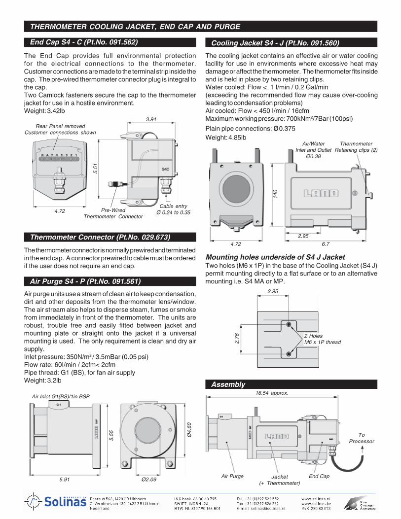
End Cap S4 - C (Pt.No. 091.562)
THERMOMETER COOLING JACKET, END CAP AND PURGE
The cooling jacket contains an effective air or water coolingfacility for use in environments where excessive heat maydamage or affect the thermometer. The thermometer fits insideand is held in place by two retaining clips.Water cooled: Flow < 1 I/min / 0.2 Gal/min(exceeding the recommended flow may cause over-coolingleading to condensation problems)Air cooled: Flow < 450 I/min / 16cfmMaximum working pressure: 700kNm2/7Bar (100psi)
Plain pipe connections: ø0.375Weight: 4.85lb
Assembly
Air purge units use a stream of clean air to keep condensation,dirt and other deposits from the thermometer lens/window.The air stream also helps to disperse steam, fumes or smokefrom immediately in front of the thermometer. The units arerobust, trouble free and easily fitted between jacket andmounting plate or straight onto the jacket if a universalmounting is used. The only requirement is clean and dry airsupply.Inlet pressure: 350N/m2 / 3.5mBar (0.05 psi)Flow rate: 60I/min / 2cfm< 2cfmPipe thread: G1 (BS), for fan air supplyWeight: 3.2lb
Mounting holes underside of S4 J JacketTwo holes (M6 x 1P) in the base of the Cooling Jacket (S4 J)permit mounting directly to a flat surface or to an alternativemounting i.e. S4 MA or MP.
The End Cap provides full environmental protectionfor the electrical connections to the thermometer.Customer connections are made to the terminal strip inside thecap. The pre-wired thermometer connector plug is integral tothe cap.Two Camlock fasteners secure the cap to the thermometerjacket for use in a hostile environment.Weight: 3.42lb
Rear Panel removedCustomer connections shown
4.72
3.94
5.51
Pre-WiredThermometer Connector
Cable entryØ 0.24 to 0.35
Thermometer Connector (Pt.No. 029.673)
The thermometer connector is normally prewired and terminatedin the end cap. A connector prewired to cable must be orderedif the user does not require an end cap.
Air Purge S4 - P (Pt.No. 091.561)
5.91 Ø2.09
5.55 Ø
4.60
Cooling Jacket S4 - J (Pt.No. 091.560)
4.72 6.7
140
2.95
ThermometerRetaining clips (2)
Air/WaterInlet and Outlet
Ø0.38
2.95
2.76 2 Holes
M6 x 1P thread
16.54 approx.
Air Purge End CapJacket(+ Thermometer)
ToProcessor
Total Weight 15.2lb
Air Inlet G1(BS)/1in BSP
6
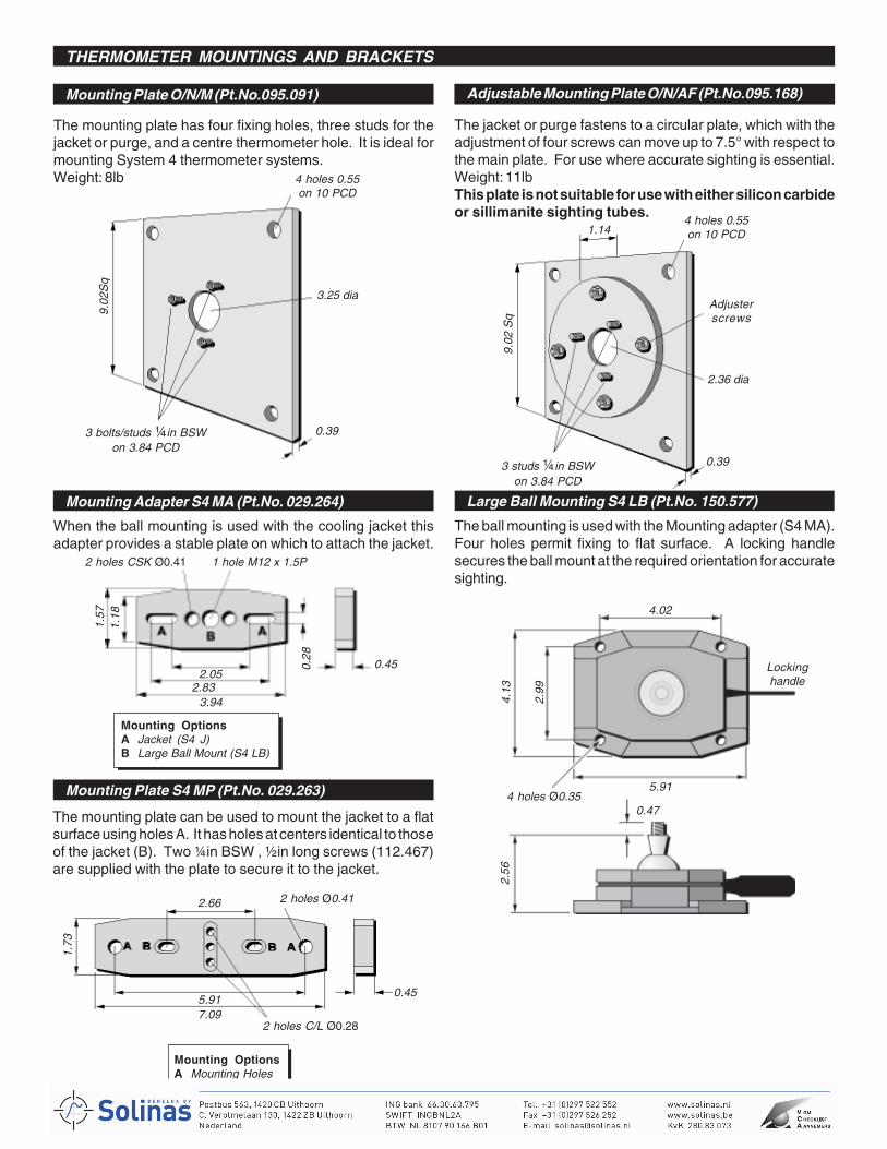
THERMOMETER MOUNTINGS AND BRACKETS
Mounting Plate O/N/M (Pt.No.095.091) Adjustable Mounting Plate O/N/AF (Pt.No.095.168)
Mounting Adapter S4 MA (Pt.No. 029.264) Large Ball Mounting S4 LB (Pt.No. 150.577)
Mounting Plate S4 MP (Pt.No. 029.263)
The mounting plate has four fixing holes, three studs for thejacket or purge, and a centre thermometer hole. It is ideal formounting System 4 thermometer systems.Weight: 8lb
2.66
5.917.09
0.45
2 holes C/L Ø0.28
2 holes Ø0.41
1.73
Mounting OptionsA Mounting HolesB Jacket (S4 J)
2.83
1.57
3.94
0.45
2 holes CSK Ø0.41
1.18
2.05
1 hole M12 x 1.5P
0.28
9.02
Sq
4 holes 0.55on 10 PCD
3 bolts/studs ¼in BSWon 3.84 PCD
3.25 dia
0.39
9.02
Sq
4 holes 0.55on 10 PCD
3 studs ¼in BSWon 3.84 PCD
2.36 dia
1.14
0.39
Adjusterscrews
4 holes Ø0.355.91
4.13
2.99
4.02
Lockinghandle
2.56
0.47
Mounting OptionsA Jacket (S4 J)B Large Ball Mount (S4 LB)
The jacket or purge fastens to a circular plate, which with theadjustment of four screws can move up to 7.5° with respect tothe main plate. For use where accurate sighting is essential.Weight: 11lbThis plate is not suitable for use with either silicon carbideor sillimanite sighting tubes.
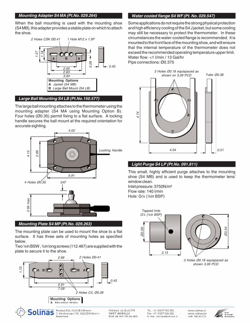
When the ball mounting is used with the cooling jacket thisadapter provides a stable plate on which to attach the jacket.
The mounting plate can be used to mount the jacket to a flatsurface using holes A. It has holes at centers identical to thoseof the jacket (B). Two ¼in BSW , ½in long screws (112.467)are supplied with the plate to secure it to the jacket.
The ball mounting is used with the Mounting adapter (S4 MA).Four holes permit fixing to flat surface. A locking handlesecures the ball mount at the required orientation for accuratesighting.
7
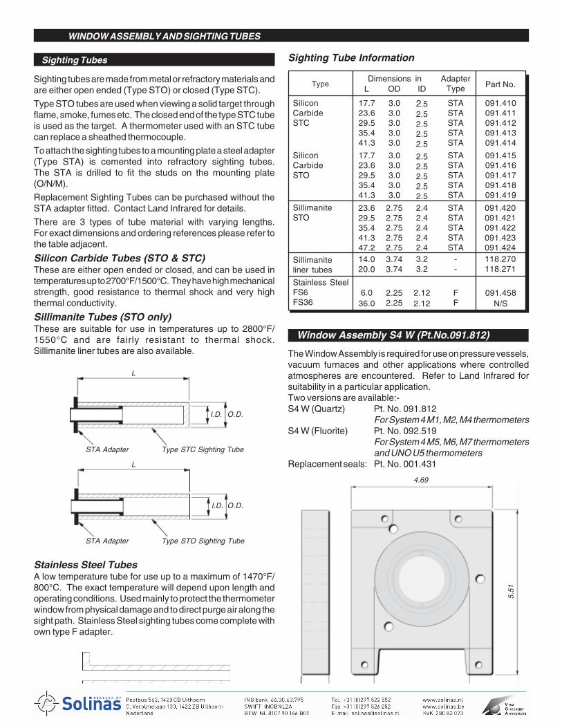
WINDOW ASSEMBLY AND SIGHTING TUBES
Sighting Tubes Sighting Tube Information
The Window Assembly is required for use on pressure vessels,vacuum furnaces and other applications where controlledatmospheres are encountered. Refer to Land Infrared forsuitability in a particular application.Two versions are available:-S4 W (Quartz) Pt. No. 091.812
For System 4 M1, M2, M4 thermometersS4 W (Fluorite) Pt. No. 092.519
For System 4 M5, M6, M7 thermometersand UNO U5 thermometers
Replacement seals: Pt. No. 001.431
Stainless Steel TubesA low temperature tube for use up to a maximum of 1470°F/800°C. The exact temperature will depend upon length andoperating conditions. Used mainly to protect the thermometerwindow from physical damage and to direct purge air along thesight path. Stainless Steel sighting tubes come complete withown type F adapter.
Sighting tubes are made from metal or refractory materials andare either open ended (Type STO) or closed (Type STC).
Type STO tubes are used when viewing a solid target throughflame, smoke, fumes etc. The closed end of the type STC tubeis used as the target. A thermometer used with an STC tubecan replace a sheathed thermocouple.
To attach the sighting tubes to a mounting plate a steel adapter(Type STA) is cemented into refractory sighting tubes.The STA is drilled to fit the studs on the mounting plate(O/N/M).
Replacement Sighting Tubes can be purchased without theSTA adapter fitted. Contact Land Infrared for details.
There are 3 types of tube material with varying lengths.For exact dimensions and ordering references please refer tothe table adjacent.
Silicon Carbide Tubes (STO & STC)These are either open ended or closed, and can be used intemperatures up to 2700°F/1500°C. They have high mechanicalstrength, good resistance to thermal shock and very highthermal conductivity.
Sillimanite Tubes (STO only)These are suitable for use in temperatures up to 2800°F/1550°C and are fairly resistant to thermal shock.Sillimanite liner tubes are also available.
L
STA Adapter Type STC Sighting Tube
I.D. O.D.
L
STA Adapter Type STO Sighting Tube
I.D. O.D.
TypeDimensions in Adapter
Type Part No.
SiliconCarbideSTC
SiliconCarbideSTO
SillimaniteSTO
Sillimaniteliner tubes
Stainless SteelFS6FS36
L OD ID
17.723.629.535.441.3
17.723.629.535.441.3
23.629.535.441.347.2
6.036.0
14.020.0
4.69
3.151.02
5.51
Window Assembly S4 W (Pt.No.091.812)
3.03.03.03.03.0
3.03.03.03.03.0
2.752.752.752.752.75
2.252.25
3.743.74
2.52.52.52.52.5
2.52.52.52.52.52.42.42.42.42.4
2.122.12
3.23.2
STASTASTASTASTA
STASTASTASTASTA
STASTASTASTASTA
FF
--
091.410091.411091.412091.413091.414
091.415091.416091.417091.418091.419
091.420091.421091.422091.423091.424
091.458N/S
118.270118.271
8
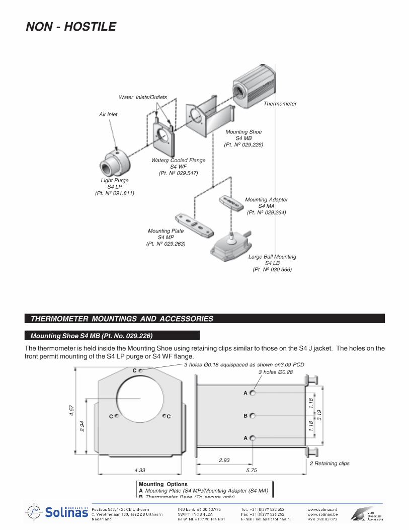
NON - HOSTILE
THERMOMETER MOUNTINGS AND ACCESSORIES
Mounting Shoe S4 MB (Pt. No. 029.226)
Mounting ShoeS4 MB
(Pt. Nº 029.226)
Waterg Cooled FlangeS4 WF
(Pt. Nº 029.547)Light Purge
S4 LP(Pt. Nº 091.811)
Air Inlet
Water Inlets/Outlets
Mounting AdapterS4 MA
(Pt. Nº 029.264)
Mounting PlateS4 MP
(Pt. Nº 029.263)
Large Ball MountingS4 LB
(Pt. Nº 030.566)
Thermometer
4.33 5.75
2.93
2.94
4.57
3.19
1.18
1.18
3 holes Ø0.18 equispaced as shown on3.09 PCD3 holes Ø0.28
Mounting OptionsA Mounting Plate (S4 MP)/Mounting Adapter (S4 MA)B Thermometer Base (To secure only)C Water Cooled Flange (S4 WF)/Light Purge (S4 LP)
A
A
BCC
C
2 Retaining clips
The thermometer is held inside the Mounting Shoe using retaining clips similar to those on the S4 J jacket. The holes on thefront permit mounting of the S4 LP purge or S4 WF flange.
9
Large Ball Mounting S4 LB (Pt.No.150.577)
Mounting Adapter S4 MA (Pt.No. 029.264) Water cooled flange S4 WF (Pt. No. 029.547)
Mounting Plate S4 MP (Pt.No. 029.263)
Light Purge S4 LP (Pt.No. 091.811)
2 Holes CSK Ø0.41 1 Hole M12 x 1.5P
3.942.832.05
1.57
1.18
0.28
0.45
A AB
Mounting OptionsA Jacket (S4 MB)B Large Ball Mount (S4 LB)
4.04 0.51
Tube Ø0.38
4.74
3 Holes Ø0.18 equispaced asshown on 3.09 PCD
3 Holes Ø0.18 equispaced asshown 3.09 PCD
3.15
Ø2.
09
Tapped holeG¼ (¼in BSP)
Ø3.
54
2 Holes Ø0.412.66
7.095.91
1.73
0.45
A AB B
Mounting OptionsA Mounting HolesB Jacket (S4 MB)
2 Holes C/L Ø0.28
4.02
5.91
2.99
4.13
Locking Handle
4 Holes Ø0.35 0.47
2.56
max
.When the ball mounting is used with the mounting shoe(S4 MB), this adapter provides a stable plate on which to attachthe shoe.
The mounting plate can be used to mount the shoe to a flatsurface. It has three sets of mounting holes as specifiedbelow.Two ¼in BSW , ½in long screws (112.467) are supplied with theplate to secure it to the shoe.
The large ball mounting attaches to the thermometer using themounting adapter (S4 MA using Mounting Option B).Four holes (Ø0.35) permit fixing to a flat surface. A lockinghandle secures the ball mount at the required orientation foraccurate sighting.
Some applications do not require the strong physical protectionand high efficiency cooling of the S4 J jacket, but some coolingmay still be necessary to protect the thermometer. In thesecircumstances the water-cooled flange is recommended. It ismounted to the front face of the mounting shoe, and will ensurethat the internal temperature of the thermometer does notexceed the recommended operating temperature upper limit.Water flow: <1 I/min / 13 Gal/hrPipe connections: Ø0.375
This small, highly efficient purge attaches to the mountingshoe (S4 MB) and is used to keep the thermometer lens/window clean.Inlet pressure: 3750N/m²Flow rate: 140 l/minHole: G¼ (¼in BSP)
10
LABORATORY
THERMOMETER MOUNTINGS AND ACCESSORIES
Mounting Adapter S4 MA (Pt.No. 029.264)
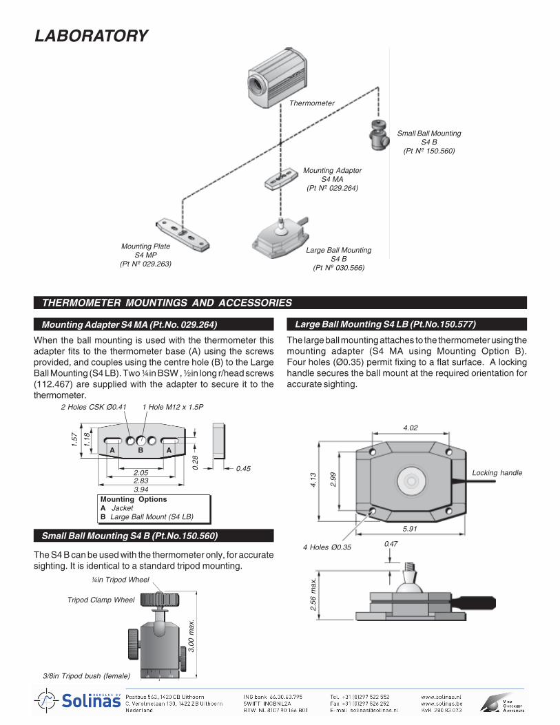
The large ball mounting attaches to the thermometer using themounting adapter (S4 MA using Mounting Option B).Four holes (Ø0.35) permit fixing to a flat surface. A lockinghandle secures the ball mount at the required orientation foraccurate sighting.
Small Ball Mounting S4 B (Pt.No.150.560)
Mounting PlateS4 MP
(Pt Nº 029.263)
Mounting AdapterS4 MA
(Pt Nº 029.264)
Small Ball MountingS4 B
(Pt Nº 150.560)
Thermometer
2 Holes CSK Ø0.41 1 Hole M12 x 1.5P
3.942.832.05
1.57
1.18
0.28
0.45
A AB
Mounting OptionsA JacketB Large Ball Mount (S4 LB)
4.02
5.91
2.99
4.13
Locking handle
4 Holes Ø0.35 0.47
2.56
max
.¼in Tripod Wheel
3/8in Tripod bush (female)fitted with removable
¼in adapter Ø1.38
3.00
max
.
Large Ball MountingS4 B
(Pt Nº 030.566)
When the ball mounting is used with the thermometer thisadapter fits to the thermometer base (A) using the screwsprovided, and couples using the centre hole (B) to the LargeBall Mounting (S4 LB). Two ¼in BSW , ½in long r/head screws(112.467) are supplied with the adapter to secure it to thethermometer.
Tripod Clamp Wheel
The S4 B can be used with the thermometer only, for accuratesighting. It is identical to a standard tripod mounting.
Large Ball Mounting S4 LB (Pt.No.150.577)
11
COMPLETE FIBRCOMPLETE FIBRCOMPLETE FIBRCOMPLETE FIBRCOMPLETE FIBROPTIC OPTIC OPTIC OPTIC OPTIC THERMOMETER SYSTEMSTHERMOMETER SYSTEMSTHERMOMETER SYSTEMSTHERMOMETER SYSTEMSTHERMOMETER SYSTEMS
Opt
ic H
ead
Opt
ic H
ead
Opt
ic H
ead
Opt
ic H
ead
LA
BO
RA
TO
RY
Fib
ropt
ic A
dapt
erS
4 F
A(P
t. N
º 02
9.23
8)
Sm
all B
all M
ount
S4
B(P
t. N
º 15
0.56
0)
Fib
ropt
ic A
ngle
Bra
cket
S4
FB
(Pt.
Nº
029.
224)
Larg
e B
all M
ount
S4
LB(P
t. N
º 03
0.56
6)
Larg
e B
all M
ount
S4
LB
Ada
pter
NO
N-H
OS
TIL
E
EX
IST
ING
SY
ST
EM
3M
OU
NTI
NG
S
IND
US
TR
IAL
Ada
pter
& A
ir P
urge
(Pt.
Nº
029.
870)
Ada
pter
, A
ir P
urge
&A
djus
tabl
e M
ount
ing
Fla
nge
(Pt.
Nº
029.
871)
Ada
pter
, A
ir P
urge
&M
ount
ing
Pla
te(P
t. N
º 02
9.87
2)
Ada
pter
, A
ir P
urge
&M
ount
ing
Bra
cket
(Pt.
Nº
029.
873)
Pro
cess
or
L &
N/H
oney
wel
l Ada
pter
(Pt.
Nº
028.
825)
Hin
ged
Adju
stab
le M
ount
ing
Plat
e(P
t. N
º 02
8.74
5)
Det
ecto
r Mod
ule
Ligh
t Gui
de
Ada
pter
, Air
Pur
ge &
Mou
ntin
g P
late
Opt
ic H
ead
Targ
et
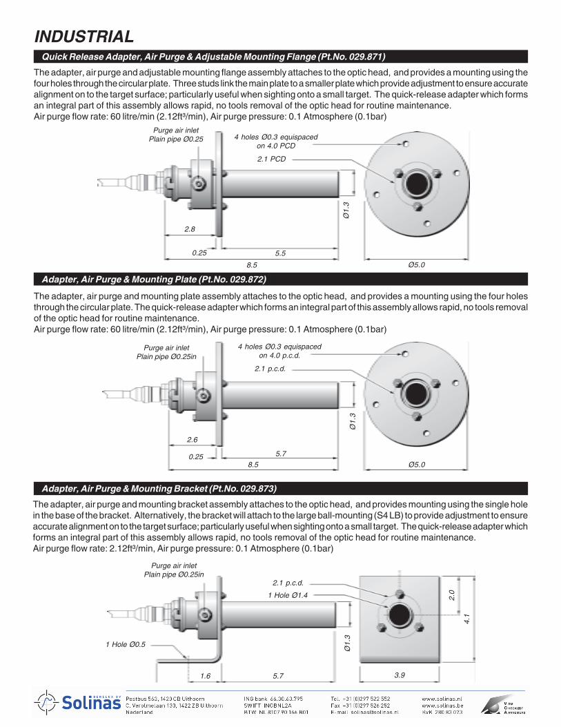
12
INDUSTRIALQuick Release Adapter, Air Purge & Adjustable Mounting Flange (Pt.No. 029.871)
Adapter, Air Purge & Mounting Plate (Pt.No. 029.872)
Adapter, Air Purge & Mounting Bracket (Pt.No. 029.873)
The adapter, air purge and adjustable mounting flange assembly attaches to the optic head, and provides a mounting using thefour holes through the circular plate. Three studs link the main plate to a smaller plate which provide adjustment to ensure accuratealignment on to the target surface; particularly useful when sighting onto a small target. The quick-release adapter which formsan integral part of this assembly allows rapid, no tools removal of the optic head for routine maintenance.Air purge flow rate: 60 litre/min (2.12ft³/min), Air purge pressure: 0.1 Atmosphere (0.1bar)
2.8
8.5
5.50.25
Purge air inletPlain pipe Ø0.25 4 holes Ø0.3 equispaced
on 4.0 PCD
2.1 PCD
Ø5.0
Ø1.
3
The adapter, air purge and mounting plate assembly attaches to the optic head, and provides a mounting using the four holesthrough the circular plate. The quick-release adapter which forms an integral part of this assembly allows rapid, no tools removalof the optic head for routine maintenance.Air purge flow rate: 60 litre/min (2.12ft³/min), Air purge pressure: 0.1 Atmosphere (0.1bar)
2.6
8.5
5.70.25
Purge air inletPlain pipe Ø0.25in
4 holes Ø0.3 equispacedon 4.0 p.c.d.
2.1 p.c.d.
Ø5.0
Ø1.
3
The adapter, air purge and mounting bracket assembly attaches to the optic head, and provides mounting using the single holein the base of the bracket. Alternatively, the bracket will attach to the large ball-mounting (S4 LB) to provide adjustment to ensureaccurate alignment on to the target surface; particularly useful when sighting onto a small target. The quick-release adapter whichforms an integral part of this assembly allows rapid, no tools removal of the optic head for routine maintenance.Air purge flow rate: 2.12ft³/min, Air purge pressure: 0.1 Atmosphere (0.1bar)
3.9
2.0
4.1
5.7
Ø1.
3
2.1 p.c.d.
1 Hole Ø1.4
Purge air inletPlain pipe Ø0.25in
1 Hole Ø0.5
3.1
1.6
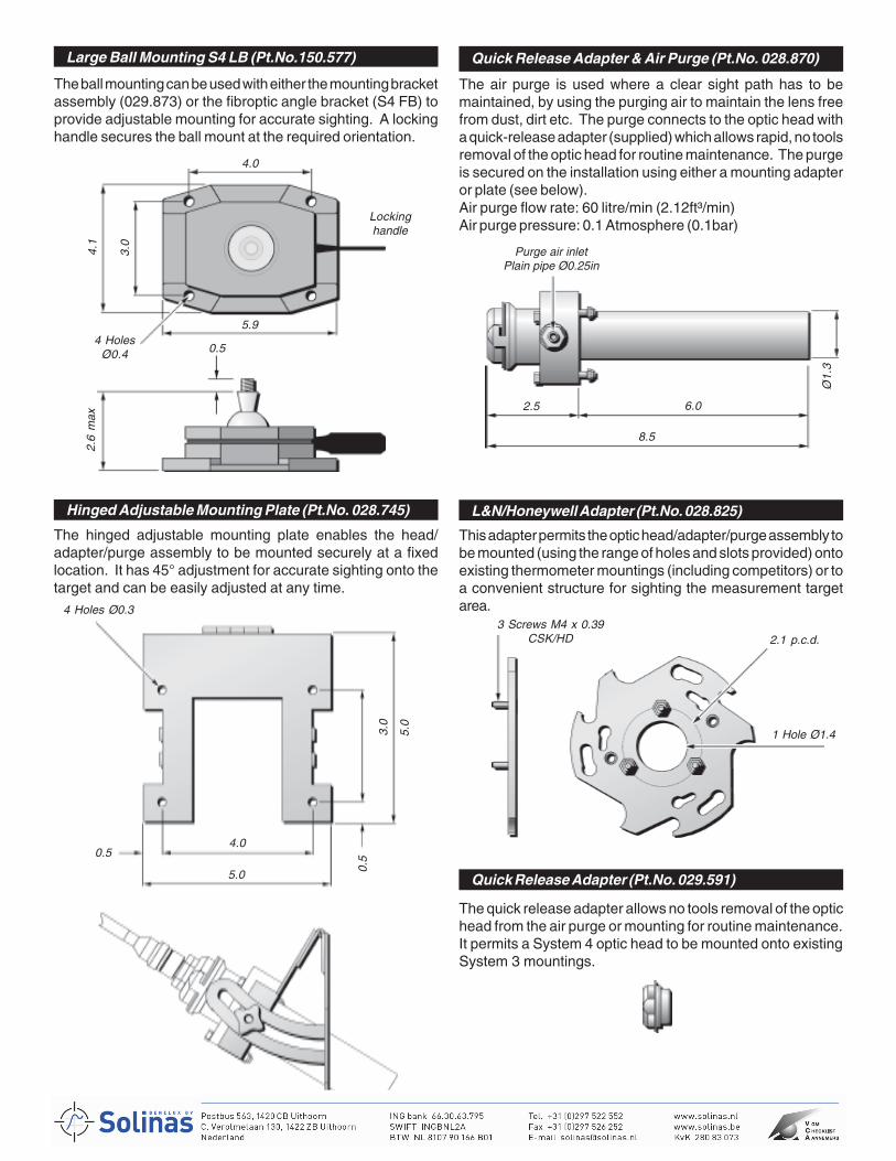
13
Large Ball Mounting S4 LB (Pt.No.150.577) Quick Release Adapter & Air Purge (Pt.No. 028.870)
Hinged Adjustable Mounting Plate (Pt.No. 028.745)
Quick Release Adapter (Pt.No. 029.591)
L&N/Honeywell Adapter (Pt.No. 028.825)
4 Holes Ø0.3
5.0
View showing mounting holes
The ball mounting can be used with either the mounting bracketassembly (029.873) or the fibroptic angle bracket (S4 FB) toprovide adjustable mounting for accurate sighting. A lockinghandle secures the ball mount at the required orientation.
4.0
Lockinghandle
4.1
3.0
5.9
2.6
max
0.54 Holes
Ø0.4
The hinged adjustable mounting plate enables the head/adapter/purge assembly to be mounted securely at a fixedlocation. It has 45° adjustment for accurate sighting onto thetarget and can be easily adjusted at any time.
3.0
0.5
5.0
4.00.5
The air purge is used where a clear sight path has to bemaintained, by using the purging air to maintain the lens freefrom dust, dirt etc. The purge connects to the optic head witha quick-release adapter (supplied) which allows rapid, no toolsremoval of the optic head for routine maintenance. The purgeis secured on the installation using either a mounting adapteror plate (see below).Air purge flow rate: 60 litre/min (2.12ft³/min)Air purge pressure: 0.1 Atmosphere (0.1bar)
Ø1.
3
2.5 6.0
8.5
Purge air inletPlain pipe Ø0.25in
This adapter permits the optic head/adapter/purge assembly tobe mounted (using the range of holes and slots provided) ontoexisting thermometer mountings (including competitors) or toa convenient structure for sighting the measurement targetarea.
3 Screws M4 x 0.39CSK/HD 2.1 p.c.d.
1 Hole Ø1.4
The quick release adapter allows no tools removal of the optichead from the air purge or mounting for routine maintenance.It permits a System 4 optic head to be mounted onto existingSystem 3 mountings.
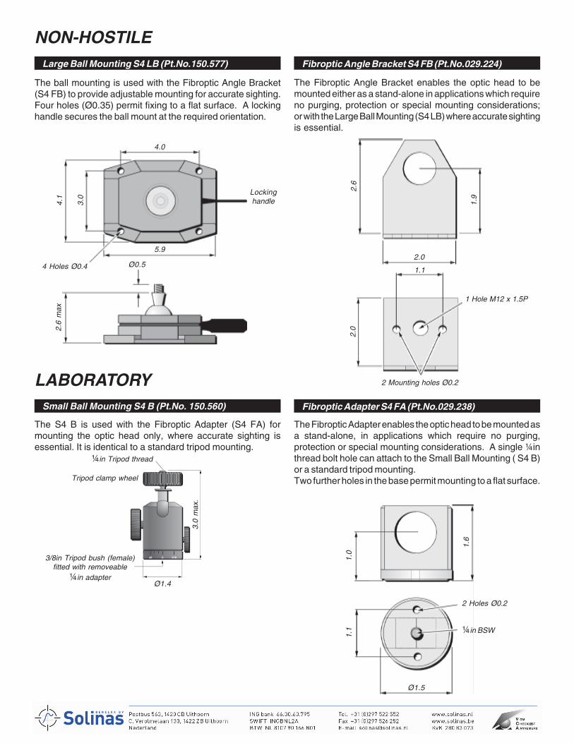
14
NON-HOSTILELarge Ball Mounting S4 LB (Pt.No.150.577) Fibroptic Angle Bracket S4 FB (Pt.No.029.224)
LABORATORYFibroptic Adapter S4 FA (Pt.No.029.238)Small Ball Mounting S4 B (Pt.No. 150.560)
4.0
2 Mounting holes Ø0.2
2.0
2.6
Ø1.4
The ball mounting is used with the Fibroptic Angle Bracket(S4 FB) to provide adjustable mounting for accurate sighting.Four holes (Ø0.35) permit fixing to a flat surface. A lockinghandle secures the ball mount at the required orientation.
The Fibroptic Angle Bracket enables the optic head to bemounted either as a stand-alone in applications which requireno purging, protection or special mounting considerations;or with the Large Ball Mounting (S4 LB) where accurate sightingis essential.
5.9
Lockinghandle4.
1
3.0
2.6
max
Ø0.54 Holes Ø0.4
¼in Tripod thread
Tripod clamp wheel
The S4 B is used with the Fibroptic Adapter (S4 FA) formounting the optic head only, where accurate sighting isessential. It is identical to a standard tripod mounting.
3.0
max
.
3/8in Tripod bush (female)fitted with removeable
¼in adapter
2.0
1.1
1 Hole M12 x 1.5P
1.9
The Fibroptic Adapter enables the optic head to be mounted asa stand-alone, in applications which require no purging,protection or special mounting considerations. A single ¼inthread bolt hole can attach to the Small Ball Mounting ( S4 B)or a standard tripod mounting.Two further holes in the base permit mounting to a flat surface.
Ø1.5
1.1 ¼in BSW
2 Holes Ø0.2
1.6
1.0
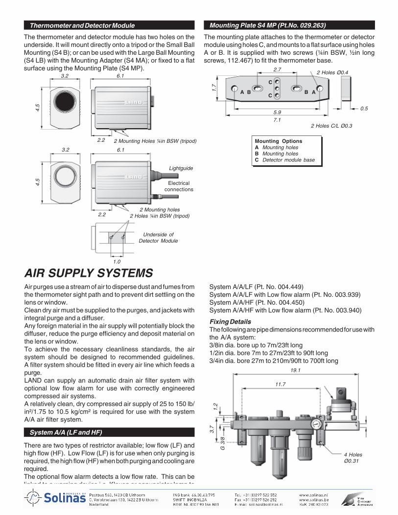
15
Mounting Plate S4 MP (Pt.No. 029.263)Thermometer and Detector Module
AIR SUPPLY SYSTEMSAir purges use a stream of air to disperse dust and fumes fromthe thermometer sight path and to prevent dirt settling on thelens or window.Clean dry air must be supplied to the purges, and jackets withintegral purge and a diffuser.Any foreign material in the air supply will potentially block thediffuser, reduce the purge efficiency and deposit material onthe lens or window.To achieve the necessary cleanliness standards, the airsystem should be designed to recommended guidelines.A filter system should be fitted in every air line which feeds apurge.LAND can supply an automatic drain air filter system withoptional low flow alarm for use with correctly engineeredcompressed air systems.A relatively clean, dry compressed air supply of 25 to 150 lb/in²/1.75 to 10.5 kg/cm² is required for use with the systemA/A air filter system.
Note: Replacement filters and other spares are available from LandInfrared.
2 Holes C/L Ø0.3
0.5
Mounting OptionsA Mounting holesB Mounting holesC Detector module base
11.7
19.1
4 HolesØ0.31
1.2
3.7
G 3
/8
3.2 6.1
4.5
2.2 2 Mounting Holes ¼in BSW (tripod)
The thermometer and detector module has two holes on theunderside. It will mount directly onto a tripod or the Small BallMounting (S4 B); or can be used with the Large Ball Mounting(S4 LB) with the Mounting Adapter (S4 MA); or fixed to a flatsurface using the Mounting Plate (S4 MP).
There are two types of restrictor available; low flow (LF) andhigh flow (HF). Low Flow (LF) is for use when only purging isrequired, the high flow (HF) when both purging and cooling arerequired.The optional flow alarm detects a low flow rate. This can belinked to a warning device i.e. Klaxon or annunciator lamp toalarm once the flow falls below the required rate.
System A/A/LF (Pt. No. 004.449)System A/A/LF with Low flow alarm (Pt. No. 003.939)System A/A/HF (Pt. No. 004.450)System A/A/HF with Low flow alarm (Pt. No. 003.940)
Fixing DetailsThe following are pipe dimensions recommended for use withthe A/A system:3/8in dia. bore up to 7m/23ft long1/2in dia. bore 7m to 27m/23ft to 90ft long3/4in dia. bore 27m to 210m/90ft to 700ft long
System A/A (LF and HF)
2.22 Mounting holes
2 Holes ¼in BSW (tripod)
Underside ofDetector Module
1.0
Electricalconnections
6.1
Lightguide
4.5
3.2
The mounting plate attaches to the thermometer or detectormodule using holes C, and mounts to a flat surface using holesA or B. It is supplied with two screws (¼in BSW, ½in longscrews, 112.467) to fit the thermometer base.
2.7 2 Holes Ø0.4
1.7
A B B A
C
C
5.97.1
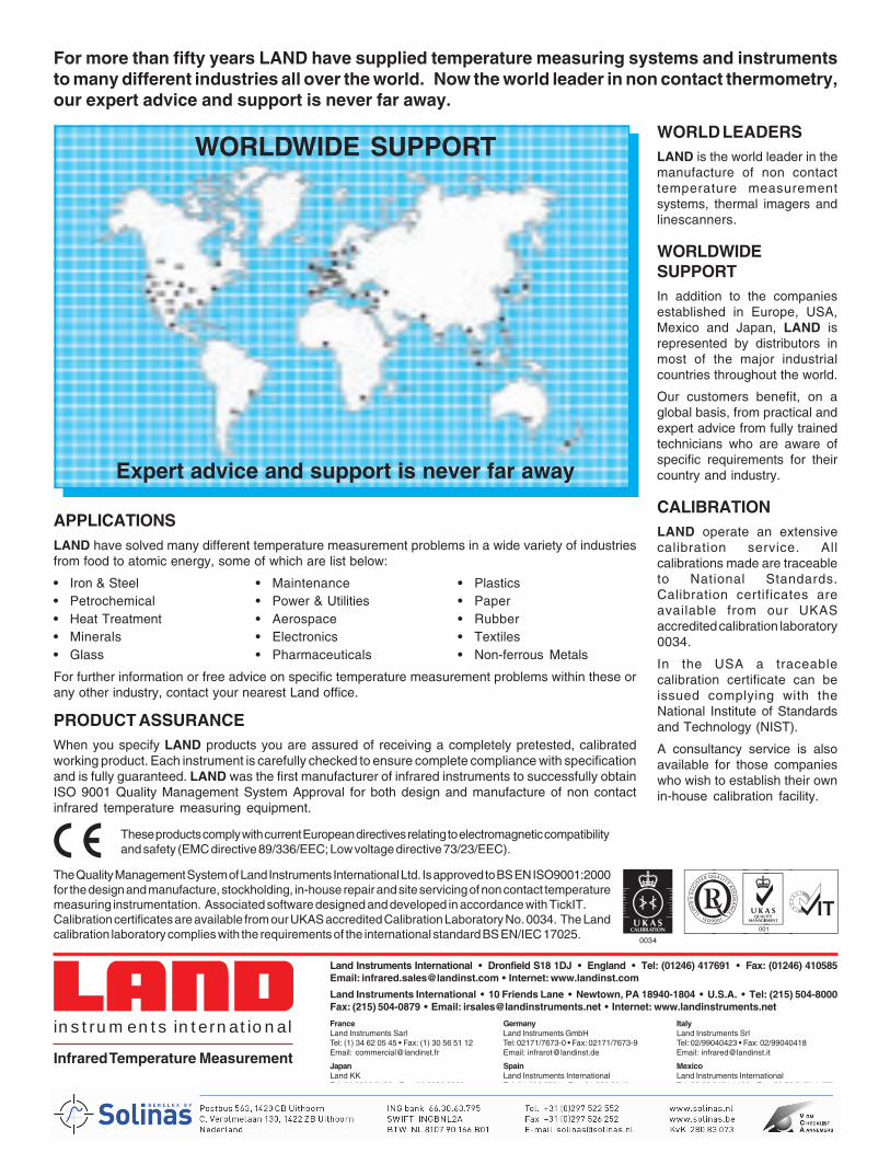
abcinstruments international
Printed in England Continuous product development may make it necessary to change these details without notice. S4M100E-US/0503
For more than fifty years LAND have supplied temperature measuring systems and instrumentsto many different industries all over the world. Now the world leader in non contact thermometry,our expert advice and support is never far away.
WORLD LEADERSLAND is the world leader in themanufacture of non contacttemperature measurementsystems, thermal imagers andlinescanners.
WORLDWIDESUPPORTIn addition to the companiesestablished in Europe, USA,Mexico and Japan, LAND isrepresented by distributors inmost of the major industrialcountries throughout the world.
Our customers benefit, on aglobal basis, from practical andexpert advice from fully trainedtechnicians who are aware ofspecific requirements for theircountry and industry.
CALIBRATIONLAND operate an extensivecalibration service. Allcalibrations made are traceableto National Standards.Calibration certificates areavailable from our UKASaccredited calibration laboratory0034.
In the USA a traceablecalibration certificate can beissued complying with theNational Institute of Standardsand Technology (NIST).
A consultancy service is alsoavailable for those companieswho wish to establish their ownin-house calibration facility.
APPLICATIONSLAND have solved many different temperature measurement problems in a wide variety of industriesfrom food to atomic energy, some of which are list below:
• Iron & Steel • Maintenance • Plastics• Petrochemical • Power & Utilities • Paper• Heat Treatment • Aerospace • Rubber• Minerals • Electronics • Textiles• Glass • Pharmaceuticals • Non-ferrous Metals
For further information or free advice on specific temperature measurement problems within these orany other industry, contact your nearest Land office.
PRODUCT ASSURANCEWhen you specify LAND products you are assured of receiving a completely pretested, calibratedworking product. Each instrument is carefully checked to ensure complete compliance with specificationand is fully guaranteed. LAND was the first manufacturer of infrared instruments to successfully obtainISO 9001 Quality Management System Approval for both design and manufacture of non contactinfrared temperature measuring equipment.
These products comply with current European directives relating to electromagnetic compatibilityand safety (EMC directive 89/336/EEC; Low voltage directive 73/23/EEC).
WORLDWIDE SUPPORT
Expert advice and support is never far away
The Quality Management System of Land Instruments International Ltd. Is approved to BS EN ISO9001:2000for the design and manufacture, stockholding, in-house repair and site servicing of non contact temperaturemeasuring instrumentation. Associated software designed and developed in accordance with TickIT.Calibration certificates are available from our UKAS accredited Calibration Laboratory No. 0034. The Landcalibration laboratory complies with the requirements of the international standard BS EN/IEC 17025.
A
Land Instruments International • Dronfield S18 1DJ • England • Tel: (01246) 417691 • Fax: (01246) 410585Email: [email protected] • Internet: www.landinst.com
Land Instruments International • 10 Friends Lane • Newtown, PA 18940-1804 • U.S.A. • Tel: (215) 504-8000Fax: (215) 504-0879 • Email: [email protected] • Internet: www.landinstruments.net
France Germany ItalyLand Instruments Sarl Land Instruments GmbH Land Instruments SrlTel: (1) 34 62 05 45 • Fax: (1) 30 56 51 12 Tel: 02171/7673-0 • Fax: 02171/7673-9 Tel: 02/99040423 • Fax: 02/99040418Email: [email protected] Email: [email protected] Email: [email protected]
Japan Spain MexicoLand KK Land Instruments International Land Instruments InternationalTel: 06 6330 5153 • Fax: 06 6330 5338 Tel: 91 630 0791 • Fax: 91 630 2918 Tel: 52 55 9171 1466 • Fax: 52 55 9171 1477Email: [email protected] Email: [email protected] Email: [email protected]
Infrared Temperature Measurement
abcdefgabc


![Index []...Index Index 1 RESISTANCE THERMOMETERS 34 GÜNTHER GmbH Temperature Measurement Technology GÜNTHER Temperature Sensors in Action Principles of Temperature Measurement](https://img.pdfslide.us/doc/110x75/60bb10b973d4582e864f0710/index-index-index-1-resistance-thermometers-34-goenther-gmbh-temperature.jpg)