Embed Size (px)
Citation preview
ODIN-W2 series Stand-alone multiradio modules with Wi-Fi & Bluetooth Getting Started
Abstract This document describes how to set up and use the ODIN-W2 series multiradio modules with Wi-Fi and Bluetooth dual mode 4.0 (Classic Bluetooth and Bluetooth Low Energy). It also provides a technical overview of the ODIN-W2 series and describes how to configure Bluetooth in ODIN-W2.
www.u-blox.com
UBX-15017452 - R02
ODIN-W2 series - Getting Started
UBX-15017452 - R02
Advance Information Page 2 of 27
Document Information
Title ODIN-W2 series
Subtitle Stand-alone multiradio modules with Wi-Fi & Bluetooth
Document type Getting Started
Document number UBX-15017452
Revision, date R02 25-Sep-2015
Document status Advance Information
Document status information
Objective Specification Document contains target values. Revised and supplementary data will be published later.
Advance Information Document contains data based on early testing. Revised and supplementary data will be published later.
Early Production Information Document contains data from product verification. Revised and supplementary data may be published later.
Production Information Document contains the final product specification.
This document applies to the following products:
Product name Type number Firmware version PCN / IN reference
ODIN-W260 ODIN-W260-00B-00 1.0.0 TBD
ODIN-W262 ODIN-W262-00B-00 1.0.0 TBD
u-blox reserves all rights to this document and the information contained herein. Products, names, logos and designs described herein may in whole or in part be subject to intellectual property rights. Reproduction, use, modification or disclosure to third parties of this document or any part thereof without the express permission of u-blox is strictly prohibited. The information contained herein is provided “as is” and u-blox assumes no liability for the use of the information. No warranty, either express or implied, is given, including but not limited, with respect to the accuracy, correctness, reliability and fitness for a particular purpose of the information. This document may be revised by u-blox at any time. For most recent documents, please visit www.u-blox.com. Copyright © 2015, u-blox AG. u-blox® is a registered trademark of u-blox Holding AG in the EU and other countries. Microsoft and Windows are either registered trademarks or trademarks of Microsoft Corporation in the United States and/or other countries. PCI, PCI Express, PCIe, and PCI-SIG are trademarks or registered trademarks of PCI-SIG. All other registered trademarks or trademarks mentioned in this document are property of their respective owners.
ODIN-W2 series - Getting Started
UBX-15017452 - R02 Advance Information Contents
Page 3 of 27
Contents Contents .............................................................................................................................. 3
1 Introduction .................................................................................................................. 5 1.1 Key features ......................................................................................................................................... 5 1.2 Modes of operation .............................................................................................................................. 6
2 Peers .............................................................................................................................. 8
3 Wi-Fi network setup ..................................................................................................... 9
4 Evaluation board ........................................................................................................ 10 4.1 LED Indications and Buttons ............................................................................................................... 10 4.2 Restore default serial settings ............................................................................................................. 11 4.3 Restore factory settings ...................................................................................................................... 11
5 Bluetooth configuration ............................................................................................ 12 5.1 Basic settings ...................................................................................................................................... 12 5.2 Client and Server ................................................................................................................................ 12 5.3 Bluetooth profiles ............................................................................................................................... 13 5.4 Multipoint .......................................................................................................................................... 13 5.5 Bluetooth security ............................................................................................................................... 14 5.6 Power Save ......................................................................................................................................... 14
6 Wi-Fi configuration .................................................................................................... 15 6.1 Network setup .................................................................................................................................... 15 6.2 Wi-Fi security ...................................................................................................................................... 15 6.3 Peer setup .......................................................................................................................................... 15 6.4 TCP Peer ............................................................................................................................................. 15 6.5 UDP Peer ............................................................................................................................................ 15
7 Use case examples ...................................................................................................... 16 7.1 Establish a Bluetooth Classic SPP connection between two ODIN-W2 ................................................. 16 7.2 Establish a Bluetooth SPP connection that connects at power up ........................................................ 17 7.3 Set a default remote peer (Wi-Fi and TCP) using DHCP and connect at startup ................................... 18 7.4 Set a default remote peer (Wi-Fi and TCP) using static IP address and connect at startup .................... 20 7.5 Connect ODIN-W2 using Wi-Fi and Cellular using Internet sharing connection ................................... 20 7.6 Connect two ODIN-W2 using Bluetooth Low Energy Serial Port Service SPS and always connected .... 24
Appendix .......................................................................................................................... 25
A List of acronyms ......................................................................................................... 25
Related documents........................................................................................................... 26
Revision history ................................................................................................................ 26

ODIN-W2 series - Getting Started
UBX-15017452 - R02 Advance Information Contents
Page 4 of 27
Contact .............................................................................................................................. 27
ODIN-W2 series - Getting Started
UBX-15017452 - R02 Advance Information Introduction
Page 5 of 27
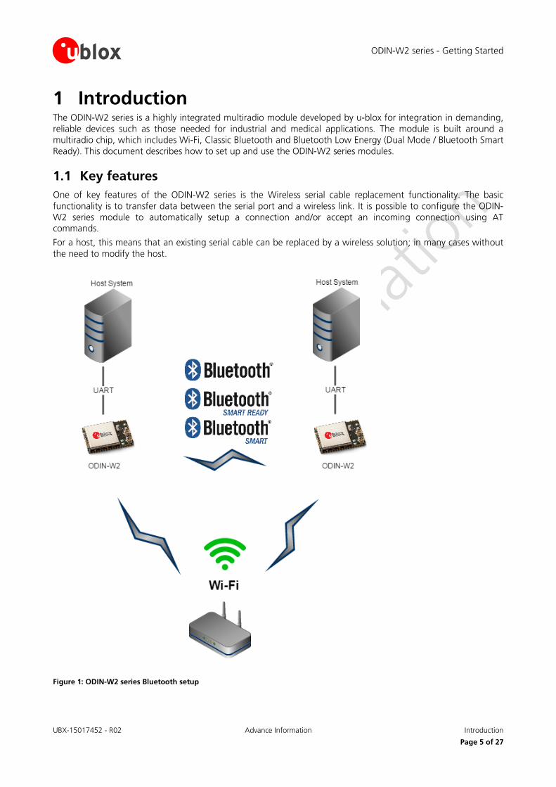
1 Introduction The ODIN-W2 series is a highly integrated multiradio module developed by u-blox for integration in demanding, reliable devices such as those needed for industrial and medical applications. The module is built around a multiradio chip, which includes Wi-Fi, Classic Bluetooth and Bluetooth Low Energy (Dual Mode / Bluetooth Smart Ready). This document describes how to set up and use the ODIN-W2 series modules.
1.1 Key features One of key features of the ODIN-W2 series is the Wireless serial cable replacement functionality. The basic functionality is to transfer data between the serial port and a wireless link. It is possible to configure the ODIN-W2 series module to automatically setup a connection and/or accept an incoming connection using AT commands.
For a host, this means that an existing serial cable can be replaced by a wireless solution; in many cases without the need to modify the host.
Figure 1: ODIN-W2 series Bluetooth setup
ODIN-W2 series - Getting Started
UBX-15017452 - R02 Advance Information Introduction
Page 6 of 27
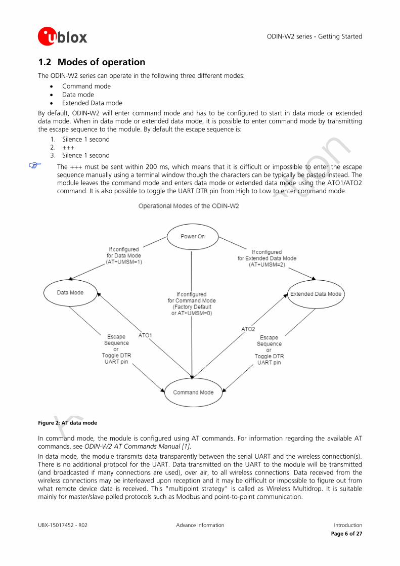
1.2 Modes of operation The ODIN-W2 series can operate in the following three different modes:
• Command mode • Data mode • Extended Data mode
By default, ODIN-W2 will enter command mode and has to be configured to start in data mode or extended data mode. When in data mode or extended data mode, it is possible to enter command mode by transmitting the escape sequence to the module. By default the escape sequence is:
1. Silence 1 second 2. +++ 3. Silence 1 second
The +++ must be sent within 200 ms, which means that it is difficult or impossible to enter the escape sequence manually using a terminal window though the characters can be typically be pasted instead. The module leaves the command mode and enters data mode or extended data mode using the ATO1/ATO2 command. It is also possible to toggle the UART DTR pin from High to Low to enter command mode.
Figure 2: AT data mode
In command mode, the module is configured using AT commands. For information regarding the available AT commands, see ODIN-W2 AT Commands Manual [1].
In data mode, the module transmits data transparently between the serial UART and the wireless connection(s). There is no additional protocol for the UART. Data transmitted on the UART to the module will be transmitted (and broadcasted if many connections are used), over air, to all wireless connections. Data received from the wireless connections may be interleaved upon reception and it may be difficult or impossible to figure out from what remote device data is received. This "multipoint strategy" is called as Wireless Multidrop. It is suitable mainly for master/slave polled protocols such as Modbus and point-to-point communication.
ODIN-W2 series - Getting Started
UBX-15017452 - R02 Advance Information Introduction
Page 7 of 27
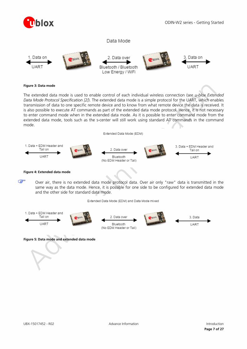
Figure 3: Data mode
The extended data mode is used to enable control of each individual wireless connection (see u-blox Extended Data Mode Protocol Specification [2]). The extended data mode is a simple protocol for the UART, which enables transmission of data to one specific remote device and to know from what remote device the data is received. It is also possible to execute AT commands as part of the extended data mode protocol. Hence, it is not necessary to enter command mode when in the extended data mode. As it is possible to enter command mode from the extended data mode, tools such as the s-center will still work using standard AT commands in the command mode.
Figure 4: Extended data mode
Over air, there is no extended data mode protocol data. Over air only "raw" data is transmitted in the same way as the data mode. Hence, it is possible for one side to be configured for extended data mode and the other side for standard data mode.
Figure 5: Data mode and extended data mode
ODIN-W2 series - Getting Started
UBX-15017452 - R02 Advance Information Peers
Page 8 of 27
2 Peers A connection consists of a sender and a receiver of data. It can also consist of a sender and several receivers in the case of a wireless multidrop/broadcast data. In both cases, every sender and receiver in a setup is referred to as a peer. Thus, a peer is capable of either receiving and/or sending data.
There are two kinds of peer classes in the serial port adapter:
• Local peer • Remote peer
The local peer is (currently) synonymous with the UART. In contrast to the local peer, the remote peer is another device or broadcast range on the network. Several remote peers can be defined if a multi-drop scenario is needed.
A remote peer is addressed using a Uniform Resource Locator, URL. These locators are strings representing nodes on internet or on a local net. This is the same addressing technology used in for example a web browser. For more information about URLs, read RFC 1738.
In general, URLs are written as follows:
<scheme>:<scheme-specific-part>
Where <scheme> is the scheme or protocol used when communicating and <scheme-specific-part> is normally the address and port number of the remote node.
For example, a web server on the internet can have the following address:
http://www.u-blox.com/
This tells the browser to use the HTTP protocol and connect to the node at address www.u-blox.com. Similar addressing scheme is used by ODIN-W2 to pinpoint the remote peer. The scheme is not "http", but the node addressing is identical.
Available schemes:
• tcp: TCP connection • udp: UDP connection, broadcast capabilities • spp: Bluetooth Serial Port Profile • dun: Bluetooth Dial Up Networking • sps: Bluetooth Low Energy u-blox Serial Port Service
Syntax:
• tcp/udp • <scheme>://ipaddress<:portnumber> • spp/dun/sps • <scheme>://bluetooth_address/
Remarks:
• IP address can be either a numeric IP address or a host and domain name that can be resolved using the configured DNS servers.
Examples
• tcp://10.0.0.9:5003 • tcp://echo.u-blox.com:7 • udp://192.168.0.42:6809 • spp://0012f3000001
A peer can be setup using either the default remote peer command (AT+UDDRP) or dynamically created using the connect peer command (AT+UDCP). A connection is closed using AT+UDCC.
To enable incoming connections, servers must be enabled using the command AT+UDSC. One server of each type can be created, but it can allow for multiple incoming connections. By default, the SPP server is enabled on Server id 0, and in Bluetooth Low Energy, enable the SPS service using the AT+UDSC command.
ODIN-W2 series - Getting Started
UBX-15017452 - R02 Advance Information Wi-Fi network setup
Page 9 of 27
3 Wi-Fi network setup To use TCP and UDP peers, at least one Wi-Fi network must be defined (and connected). This is done using the AT+UWSC and AT+UWSCA commands. To define a network, IP address assignment behavior must be defined. Default behavior is DHCP client.
ODIN-W2 series - Getting Started
UBX-15017452 - R02 Advance Information Evaluation board
Page 10 of 27
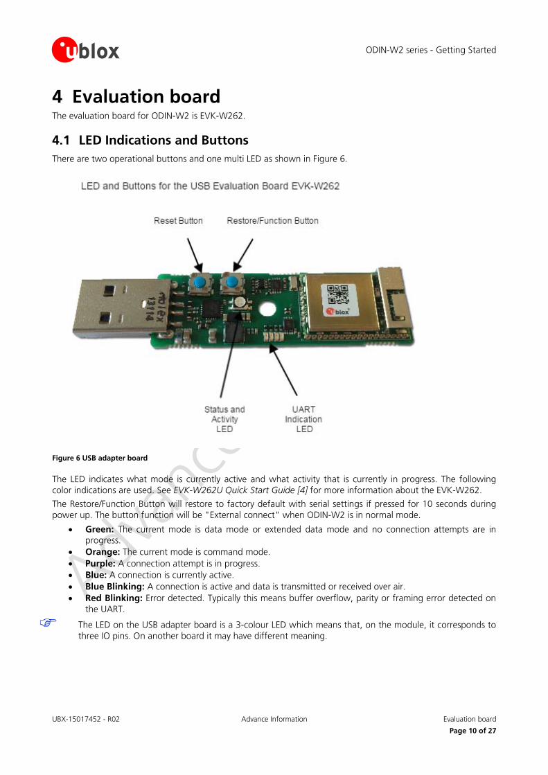
4 Evaluation board The evaluation board for ODIN-W2 is EVK-W262.
4.1 LED Indications and Buttons There are two operational buttons and one multi LED as shown in Figure 6.
Figure 6 USB adapter board
The LED indicates what mode is currently active and what activity that is currently in progress. The following color indications are used. See EVK-W262U Quick Start Guide [4] for more information about the EVK-W262.
The Restore/Function Button will restore to factory default with serial settings if pressed for 10 seconds during power up. The button function will be "External connect" when ODIN-W2 is in normal mode.
• Green: The current mode is data mode or extended data mode and no connection attempts are in progress.
• Orange: The current mode is command mode. • Purple: A connection attempt is in progress. • Blue: A connection is currently active. • Blue Blinking: A connection is active and data is transmitted or received over air. • Red Blinking: Error detected. Typically this means buffer overflow, parity or framing error detected on
the UART.
The LED on the USB adapter board is a 3-colour LED which means that, on the module, it corresponds to three IO pins. On another board it may have different meaning.
ODIN-W2 series - Getting Started
UBX-15017452 - R02 Advance Information Evaluation board
Page 11 of 27
4.2 Restore default serial settings If the Restore/Function button is pressed during power on, the module resets the serial settings and escape sequence to the default values.
• Default serial settings is 115.2 kbps, 8N1 and HW flow control enabled • Default escape sequence is +++ • Default escape sequence timing is 1s silence before and after escape sequence
4.3 Restore factory settings If both the default serial settings and the external connect button is pressed during power on, the factory settings are restored. You can also restore to factory settings using the AT+UFACTORY command followed by power off/on.
ODIN-W2 series - Getting Started
UBX-15017452 - R02 Advance Information Bluetooth configuration
Page 12 of 27
5 Bluetooth configuration You can configure the ODIN-W2 module according to specific customer requirements using AT commands (see ODIN-W2 AT Commands Manual [1]). The easiest way to get started is to use the s-center, which is a graphical user interface for sending AT-commands (see s-center Quick Start Guide [4]). The s-center allows for easy configuration with the most common AT commands.
5.1 Basic settings There are some basic commands for controlling the general Bluetooth behavior of the module.
• Connectable (AT+UBTCM): Shall other devices be able to connect to the module? This does not affect outgoing connections.
• Discoverable (AT+UBTDM): Shall the module be visible to remote devices making inquires? • Pairable (AT+UBTPM): Shall another device be able to pair (authenticate) with the module? • Bluetooth name (AT+UBTLN): The name found by remote devices making inquires. • Class of device (AT+UBTLC): Classification of what kind of device the module is. There are standard
settings according to the Bluetooth specification.
If a module has been configured to connect or accept an incoming connection to/from a remote device and if pairing is done (needed only once), it is a good idea to disable both discoverable and pairable devices for security reasons and performance.
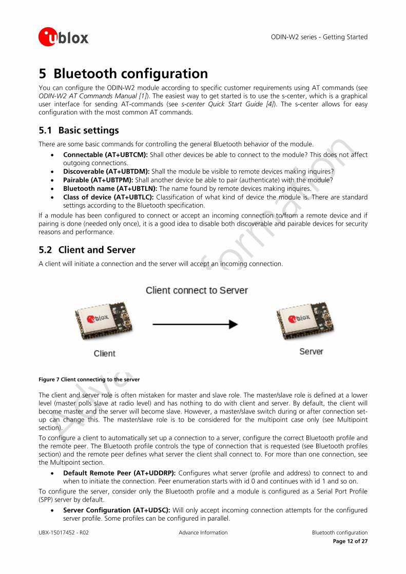
5.2 Client and Server A client will initiate a connection and the server will accept an incoming connection.
Figure 7 Client connecting to the server
The client and server role is often mistaken for master and slave role. The master/slave role is defined at a lower level (master polls slave at radio level) and has nothing to do with client and server. By default, the client will become master and the server will become slave. However, a master/slave switch during or after connection set-up can change this. The master/slave role is to be considered for the multipoint case only (see Multipoint section).
To configure a client to automatically set up a connection to a server, configure the correct Bluetooth profile and the remote peer. The Bluetooth profile controls the type of connection that is requested (see Bluetooth profiles section) and the remote peer defines what server the client shall connect to. For more than one connection, see the Multipoint section.
• Default Remote Peer (AT+UDDRP): Configures what server (profile and address) to connect to and when to initiate the connection. Peer enumeration starts with id 0 and continues with id 1 and so on.
To configure the server, consider only the Bluetooth profile and a module is configured as a Serial Port Profile (SPP) server by default.
• Server Configuration (AT+UDSC): Will only accept incoming connection attempts for the configured server profile. Some profiles can be configured in parallel.
ODIN-W2 series - Getting Started
UBX-15017452 - R02 Advance Information Bluetooth configuration
Page 13 of 27
For more than one connection, see the Multipoint section.
5.3 Bluetooth profiles The Bluetooth profiles used by the client and server define the type of connection that is accepted.
• Serial Port Profile (SPP): Serial cable emulation profile to replace existing serial cables. • Dial-Up Network (DUN): Modem emulation typically used by a Bluetooth device to access the Internet
via a mobile phone. It requires the host to have its own TCP/IP stack.
The client profile must match the server profile for a connection to be accepted.
There are some special requirements to make the SPP profile work for iPhone and Android smartphones. More information about this will be available soon.
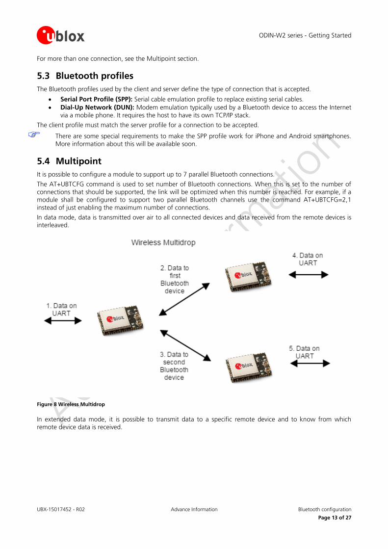
5.4 Multipoint It is possible to configure a module to support up to 7 parallel Bluetooth connections.
The AT+UBTCFG command is used to set number of Bluetooth connections. When this is set to the number of connections that should be supported, the link will be optimized when this number is reached. For example, if a module shall be configured to support two parallel Bluetooth channels use the command AT+UBTCFG=2,1 instead of just enabling the maximum number of connections.
In data mode, data is transmitted over air to all connected devices and data received from the remote devices is interleaved.
Figure 8 Wireless Multidrop
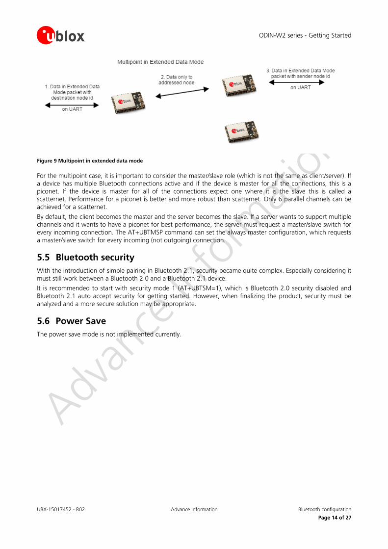
In extended data mode, it is possible to transmit data to a specific remote device and to know from which remote device data is received.
ODIN-W2 series - Getting Started
UBX-15017452 - R02 Advance Information Bluetooth configuration
Page 14 of 27
Figure 9 Multipoint in extended data mode
For the multipoint case, it is important to consider the master/slave role (which is not the same as client/server). If a device has multiple Bluetooth connections active and if the device is master for all the connections, this is a piconet. If the device is master for all of the connections expect one where it is the slave this is called a scatternet. Performance for a piconet is better and more robust than scatternet. Only 6 parallel channels can be achieved for a scatternet.
By default, the client becomes the master and the server becomes the slave. If a server wants to support multiple channels and it wants to have a piconet for best performance, the server must request a master/slave switch for every incoming connection. The AT+UBTMSP command can set the always master configuration, which requests a master/slave switch for every incoming (not outgoing) connection.
5.5 Bluetooth security With the introduction of simple pairing in Bluetooth 2.1, security became quite complex. Especially considering it must still work between a Bluetooth 2.0 and a Bluetooth 2.1 device.
It is recommended to start with security mode 1 (AT+UBTSM=1), which is Bluetooth 2.0 security disabled and Bluetooth 2.1 auto accept security for getting started. However, when finalizing the product, security must be analyzed and a more secure solution may be appropriate.
5.6 Power Save The power save mode is not implemented currently.
ODIN-W2 series - Getting Started
UBX-15017452 - R02 Advance Information Wi-Fi configuration
Page 15 of 27
6 Wi-Fi configuration To use Wi-Fi as transport for serial data, setup both the network and peers. You can setup both TCP and UDP peers and they can be both client and servers.
6.1 Network setup To setup a network, Wi-Fi Station Network configuration (AT+UWSC) and Wi-Fi Station action (AT+UWSCA) command shall be used. With the AT+UWSC command, all necessary Wi-Fi and network parameters are configured, that is, network addresses, SSID and security settings. The parameters must then be saved to the startup database (followed by a reboot) or activated before they are used. The AT+UWSCA is used to store or activate the Wi-Fi and network parameters. Multiple Wi-Fi networks can be configured, but only one can be active at any given point of time.
6.2 Wi-Fi security ODIN-W2 supports several security modes. The matrix below shows valid security combinations for the module.
Unencrypted WEP64 WEP128 TKIP AES/CCMP
Open Valid Valid Valid
Shared
WPA Valid Valid
WPA2 Valid Valid
LEAP Valid Valid Valid Valid
PEAP Valid Valid Valid Valid
Table 1: Security combinations
WEP is considered highly unsecure, is deprecated in the 802.11i specification and should not be used. TKIP is also considered as unsecure.
6.3 Peer setup Peer setup is used using the "Default Remote Peer" (AT+UDDRP) and "Server Configuration" (AT+UDSC) commands.
6.4 TCP Peer When a TCP peer is connected, data can flow in both directions irrelevant of whether the peer is a server or client.
6.5 UDP Peer For an UDP peer, the behavior differs for servers and clients. A server will accept data from any IP address sent to the activated port number.
A client can be used to both send and receive data to and from the address specified. To listen on a different port than the remote port, <local_port> can be specified in the URL; for example, to send on port 8080 and receive on port 8081 gives the following URL udp://192.168.0.1:8080/?local_port=8081.
ODIN-W2 series - Getting Started
UBX-15017452 - R02 Advance Information Use case examples
Page 16 of 27
7 Use case examples
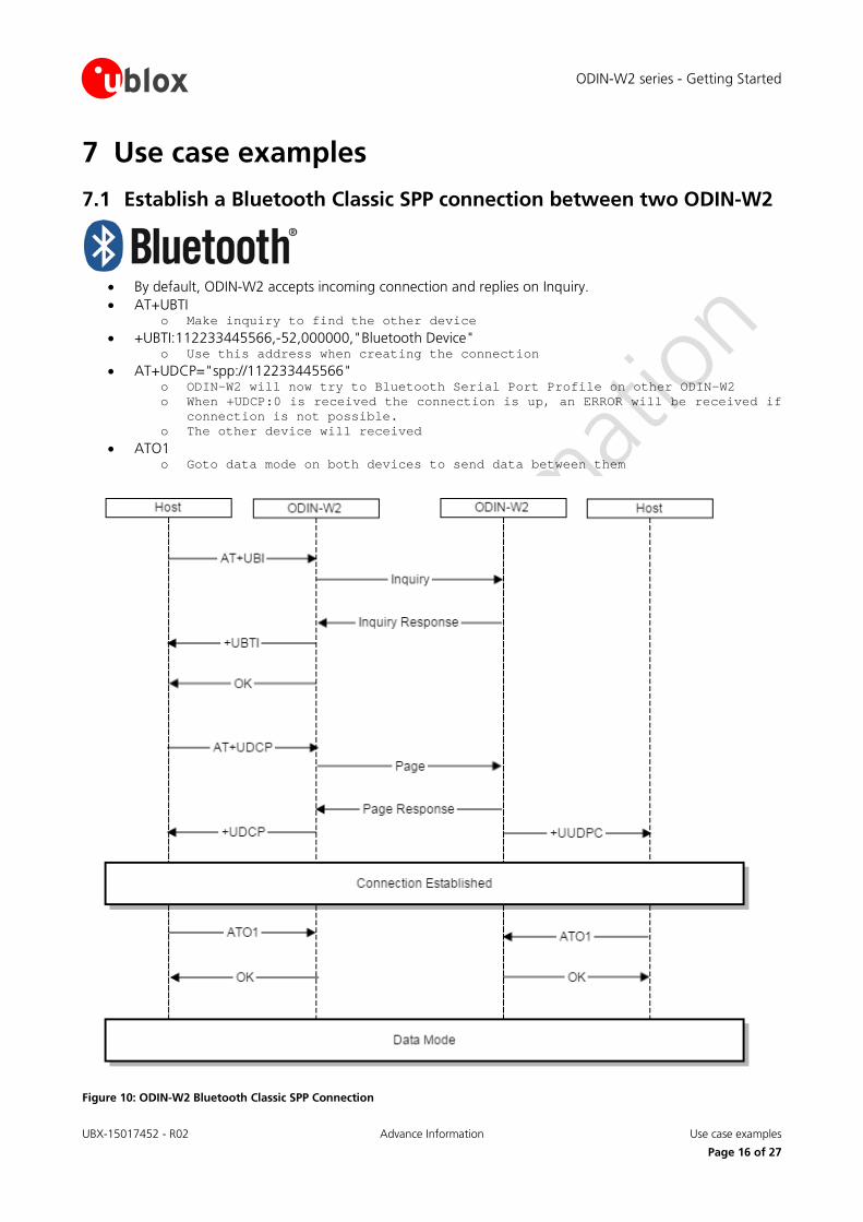
7.1 Establish a Bluetooth Classic SPP connection between two ODIN-W2
• By default, ODIN-W2 accepts incoming connection and replies on Inquiry. • AT+UBTI
o Make inquiry to find the other device • +UBTI:112233445566,-52,000000,"Bluetooth Device"
o Use this address when creating the connection • AT+UDCP="spp://112233445566"
o ODIN-W2 will now try to Bluetooth Serial Port Profile on other ODIN-W2 o When +UDCP:0 is received the connection is up, an ERROR will be received if
connection is not possible. o The other device will received
• ATO1 o Goto data mode on both devices to send data between them
Figure 10: ODIN-W2 Bluetooth Classic SPP Connection
ODIN-W2 series - Getting Started
UBX-15017452 - R02 Advance Information Use case examples
Page 17 of 27
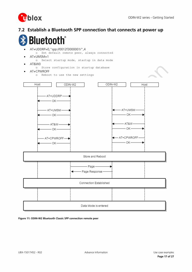
7.2 Establish a Bluetooth SPP connection that connects at power up
• AT+UDDRP=0,"spp://0012f3000001/",4
o Set default remote peer, always connected • AT+UMSM=1
o Select startup mode, startup in data mode • AT&W0
o Store configuration in startup database • AT+CPWROFF
o Reboot to use the new settings
Figure 11: ODIN-W2 Bluetooth Classic SPP connection remote peer
ODIN-W2 series - Getting Started
UBX-15017452 - R02 Advance Information Use case examples
Page 18 of 27
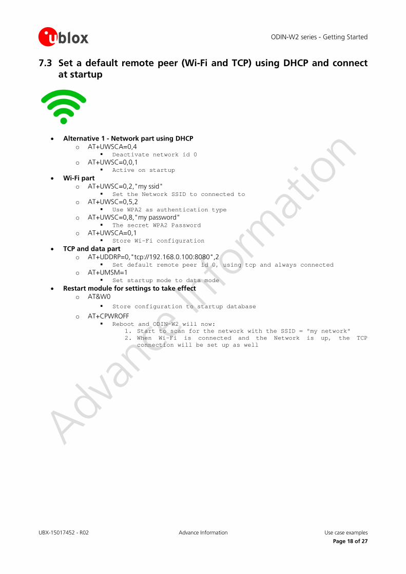
7.3 Set a default remote peer (Wi-Fi and TCP) using DHCP and connect at startup
• Alternative 1 - Network part using DHCP
o AT+UWSCA=0,4 Deactivate network id 0
o AT+UWSC=0,0,1 Active on startup
• Wi-Fi part o AT+UWSC=0,2,"my ssid"
Set the Network SSID to connected to o AT+UWSC=0,5,2
Use WPA2 as authentication type o AT+UWSC=0,8,"my password"
The secret WPA2 Password o AT+UWSCA=0,1
Store Wi-Fi configuration • TCP and data part
o AT+UDDRP=0,"tcp://192.168.0.100:8080",2 Set default remote peer id 0, using tcp and always connected
o AT+UMSM=1 Set startup mode to data mode
• Restart module for settings to take effect o AT&W0
Store configuration to startup database
o AT+CPWROFF Reboot and ODIN-W2 will now:
1. Start to scan for the network with the SSID = "my network" 2. When Wi-Fi is connected and the Network is up, the TCP
connection will be set up as well
ODIN-W2 series - Getting Started
UBX-15017452 - R02 Advance Information Use case examples
Page 19 of 27
Figure 12: ODIN-W2 Wi-Fi Connection
ODIN-W2 series - Getting Started
UBX-15017452 - R02 Advance Information Use case examples
Page 20 of 27
7.4 Set a default remote peer (Wi-Fi and TCP) using static IP address and connect at startup
• Network part using Static IP Address
o AT+UWSCA=0,4 Deactivate network id 0
o AT+UWSC=0,0,1 Active on startup
o AT+UNC=0,100,1 Disable DHCP Client (static IP address will be used)
o AT+UWSC=0,101,192.168.0.99 Network IP address
o AT+UWSC=0,102,255.255.0.0 Network Subnet mask
• Wi-Fi part o AT+UWSC=0,2,"my ssid"
Set the Network SSID to connected to o AT+UWSC=0,5,2
Use WPA2 as authentication type o AT+UWSC=0,8,"my password"
The secret WPA2 Password o AT+UWSCA=0,1
Store Wi-Fi configuration • TCP and data part
o AT+UDDRP=0,"tcp://192.168.0.100:8080",2 Set default remote peer id 0, using tcp and always connected
o AT+UMSM=1 Set startup mode to data mode
• Restart module for settings to take effect o AT&W0
Store configuration to startup database
o AT+CPWROFF Reboot and ODIN-W2 will now:
1. Start to scan for the network with the SSID = "my network" 2. When Wi-Fi is connected and the Network is up, the TCP
connection will be set up as well
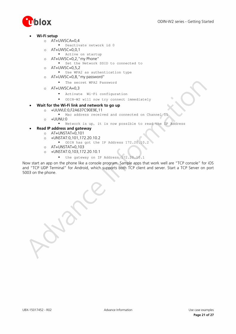
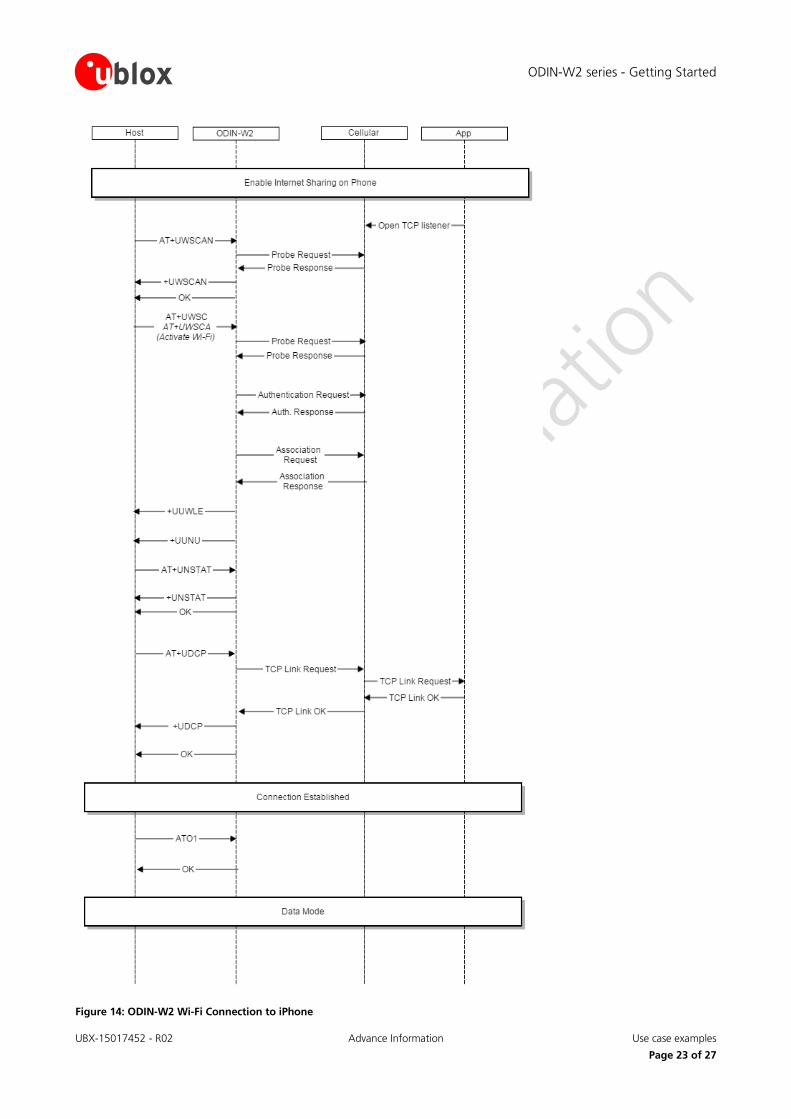
7.5 Connect ODIN-W2 using Wi-Fi and Cellular using Internet sharing connection
• Enable Internet Sharing on the Cellular and select a Wi-Fi password
o Settings > Internet Sharing > Enable • Scan for the Internet Sharing network
o AT+UWSCAN o +UWSCAN:F2A637C90E9E,1,"my phone",6,-33,16,8,8
ODIN-W2 series - Getting Started
UBX-15017452 - R02 Advance Information Use case examples
Page 21 of 27
• Wi-Fi setup o AT+UWSCA=0,4
Deactivate network id 0 o AT+UWSC=0,0,1
Active on startup o AT+UWSC=0,2,"my Phone"
Set the Network SSID to connected to o AT+UWSC=0,5,2
Use WPA2 as authentication type o AT+UWSC=0,8,"my password"
The secret WPA2 Password
o AT+UWSCA=0,3 Activate Wi-Fi configuration
ODIN-W2 will now try connect immediately
• Wait for the Wi-Fi link and network to go up o +UUWLE:0,F2A637C90E9E,11
Mac address received and connected on Channel 11 o +UUNU:0
Network is up, it is now possible to read the IP Address • Read IP address and gateway
o AT+UNSTAT=0,101 o +UNSTAT:0,101,172.20.10.2
ODIN has got the IP Address 172.20.10.2 o AT+UNSTAT=0,103 o +UNSTAT:0,103,172.20.10.1
the gateway on IP Address 172.20.10.1
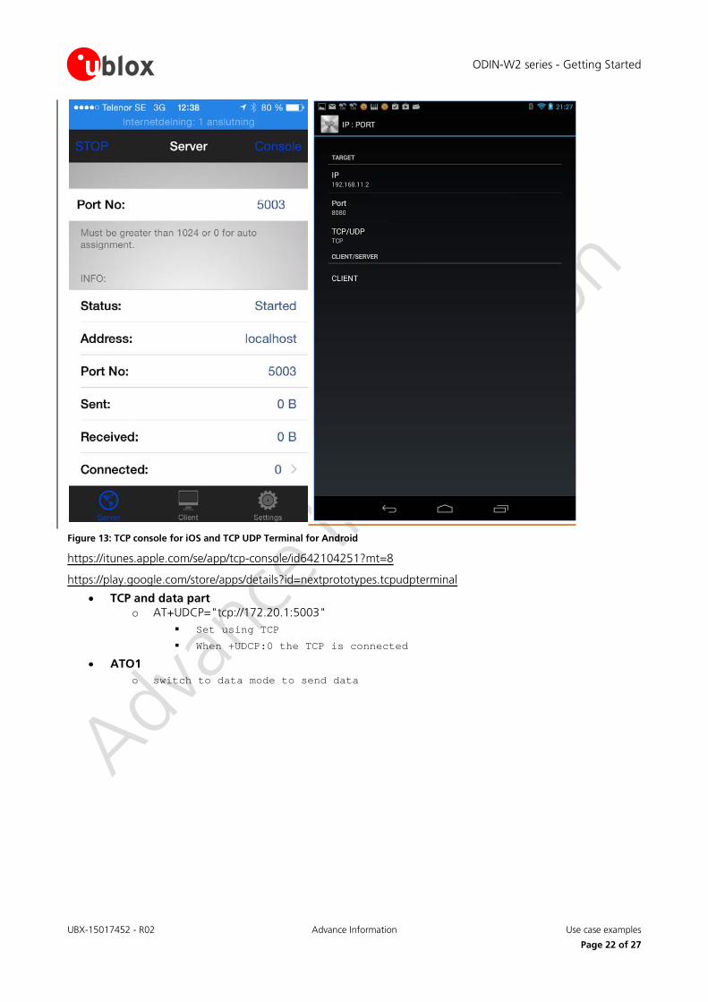
Now start an app on the phone like a console program. Sample apps that work well are “TCP console” for iOS and “TCP UDP Terminal” for Android, which supports both TCP client and server. Start a TCP Server on port 5003 on the phone.
ODIN-W2 series - Getting Started
UBX-15017452 - R02 Advance Information Use case examples
Page 22 of 27
Figure 13: TCP console for iOS and TCP UDP Terminal for Android
https://itunes.apple.com/se/app/tcp-console/id642104251?mt=8
https://play.google.com/store/apps/details?id=nextprototypes.tcpudpterminal
• TCP and data part o AT+UDCP="tcp://172.20.1:5003"
Set using TCP
When +UDCP:0 the TCP is connected
• ATO1 o switch to data mode to send data
ODIN-W2 series - Getting Started
UBX-15017452 - R02 Advance Information Use case examples
Page 23 of 27
Figure 14: ODIN-W2 Wi-Fi Connection to iPhone
ODIN-W2 series - Getting Started
UBX-15017452 - R02 Advance Information Use case examples
Page 24 of 27
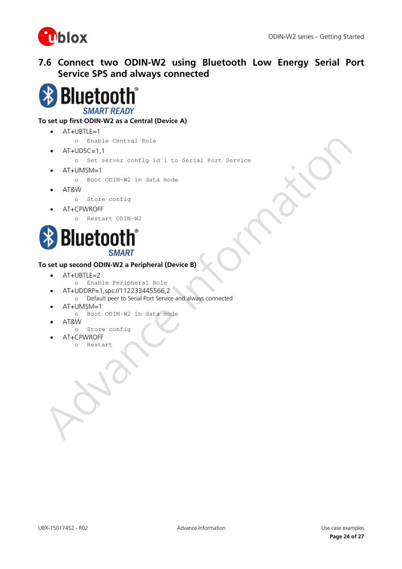
7.6 Connect two ODIN-W2 using Bluetooth Low Energy Serial Port Service SPS and always connected
To set up first ODIN-W2 as a Central (Device A)
• AT+UBTLE=1 o Enable Central Role
• AT+UDSC=1,1 o Set server config id 1 to Serial Port Service
• AT+UMSM=1 o Boot ODIN-W2 in data mode
• AT&W o Store config
• AT+CPWROFF o Restart ODIN-W2
To set up second ODIN-W2 a Peripheral (Device B)
• AT+UBTLE=2 o Enable Peripheral Role
• AT+UDDRP=1,sps://112233445566,2 o Default peer to Serial Port Service and always connected
• AT+UMSM=1 o Boot ODIN-W2 in data mode
• AT&W o Store config
• AT+CPWROFF o Restart
ODIN-W2 series - Getting Started
UBX-15017452 - R02 Advance Information Appendix
Page 25 of 27
Appendix
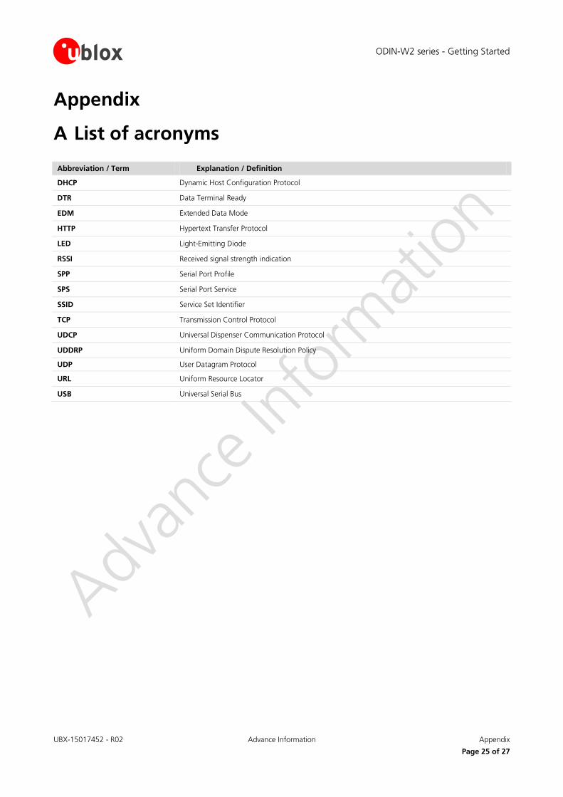
A List of acronyms
Abbreviation / Term Explanation / Definition
DHCP Dynamic Host Configuration Protocol
DTR Data Terminal Ready
EDM Extended Data Mode
HTTP Hypertext Transfer Protocol
LED Light-Emitting Diode
RSSI Received signal strength indication
SPP Serial Port Profile
SPS Serial Port Service
SSID Service Set Identifier
TCP Transmission Control Protocol
UDCP Universal Dispenser Communication Protocol
UDDRP Uniform Domain Dispute Resolution Policy
UDP User Datagram Protocol
URL Uniform Resource Locator
USB Universal Serial Bus
ODIN-W2 series - Getting Started
UBX-15017452 - R02 Advance Information Related documents
Page 26 of 27
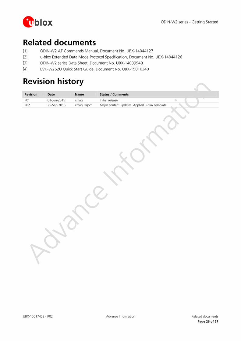
Related documents [1] ODIN-W2 AT Commands Manual, Document No. UBX-14044127
[2] u-blox Extended Data Mode Protocol Specification, Document No. UBX-14044126
[3] ODIN-W2 series Data Sheet, Document No. UBX-14039949
[4] EVK-W262U Quick Start Guide, Document No. UBX-15016340
Revision history
Revision Date Name Status / Comments
R01 01-Jun-2015 cmag Initial release
R02 25-Sep-2015 cmag, kgom Major content updates. Applied u-blox template.
ODIN-W2 series - Getting Started
UBX-15017452 - R02 Advance Information Contact
Page 27 of 27
Contact For complete contact information visit us at www.u-blox.com.
u-blox Offices
North, Central and South America
u-blox America, Inc.
Phone: +1 703 483 3180 E-mail: [email protected]
Regional Office West Coast:
Phone: +1 408 573 3640 E-mail: [email protected]
Technical Support:
Phone: +1 703 483 3185 E-mail: [email protected]
Headquarters Europe, Middle East, Africa
u-blox AG
Phone: +41 44 722 74 44 E-mail: [email protected] Support: [email protected]
Asia, Australia, Pacific
u-blox Singapore Pte. Ltd.
Phone: +65 6734 3811 E-mail: [email protected] Support: [email protected]
Regional Office Australia:
Phone: +61 2 8448 2016 E-mail: [email protected] Support: [email protected]
Regional Office China (Beijing):
Phone: +86 10 68 133 545 E-mail: [email protected] Support: [email protected]
Regional Office China (Chongqing):
Phone: +86 23 6815 1588 E-mail: [email protected] Support: [email protected]
Regional Office China (Shanghai):
Phone: +86 21 6090 4832 E-mail: [email protected] Support: [email protected]
Regional Office China (Shenzhen):
Phone: +86 755 8627 1083 E-mail: [email protected] Support: [email protected]
Regional Office India:
Phone: +91 959 1302 450 E-mail: [email protected] Support: [email protected]
Regional Office Japan (Osaka):
Phone: +81 6 6941 3660 E-mail: [email protected] Support: [email protected]
Regional Office Japan (Tokyo):
Phone: +81 3 5775 3850 E-mail: [email protected] Support: [email protected]
Regional Office Korea:
Phone: +82 2 542 0861 E-mail: [email protected] Support: [email protected]
Regional Office Taiwan:
Phone: +886 2 2657 1090 E-mail: [email protected] Support: [email protected]