Embed Size (px)
Citation preview
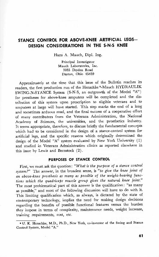
STANCE CONTROL FOR ABOVE-KNEE ARTIFICIAL LEGS- DESIGN CONSIDERATIONS IN THE S-N-S KNEE
Hans A. Mauch, Dipl. Ing.
Principal Investigator Mauch Laboratories, Inc.
3035 Dryden Road Dayton, Ohio 45439
Approximately at the time that this issue of the Bulletin reaches its readers, the first production run of the Henschke a-Mauch HYDRAULIK SWING-N-STANCE System (S-N-S, an' outgrowth of the Model "A") for prostheses for above-knee amputees will be completed and the dis- tribution of this system upon prescription to eligible veterans and to amputees at large will have started. This step marks the end of a long and sometimes arduous road, and the final success of a cooperative effort of many contributors from the Veterans Administration, the National Academy of Sciences, the universities, and the prosthetics industry. I t seems appropriate, therefore, to discuss briefly the fundamental concepts which had to be considered in the design of a stance-control system for artificial legs, and the specific reasons which originally determined the design of the Model "A" system evaluated by New York University (1) and studied in Veterans Administration clinics as reported elsewhere in this issue by Lewis and Bernstock ( 2 ) .
PURPOSES OF STANCE CONTROL
First, we must ask the question: "What is the purpose of a stance control system?" The answer, in the broadest sense, is "to give the knee joint of an above-knee prosthesis as many as possible of the weight-bearing func- tions which the quadriceps muscle group gives the natural knee joint." The most problematical part of this answer is the qualification: "as many as possible," and most of the following discussion will have to do with it. This limiting qualification which, as always, is dictated by the state of contemporary technology, implies the need for making design decisions regarding the benefits of possible functional features versus the burden they impose in terms of complexity, maintenance needs, weight increase, training requirements, cost, etc.
a U. K. Henschke, M.D., Ph.D., New York, co-inventor of the Swing and Stance Control System, Model "A."
Bulletin of Prosthetics Research-Fall 1968
The effect which the quadriceps group exerts on the knee joint in weight bearing is three fold: it can (a) extend the joint, ( b ) lock it, or ( c ) let it yield slowly. T o provide function (a ) in a prosthetic knee joint in order to enable an amputee to ascend stairs or inclines in a more natural manner would necessitate the use of substantial amounts of external power. With present day energy sources, the weight and cost penalties of such a design are usually considered prohibitive, although, in the special case of the bilateral above-knee amputee, it may appear practicable fairly soon to provide lifting power in at least one of his two prostheses. However, in the more prevalent case of the unilateral amputee, the readily available lifting power of the remaining good leg will, for the foreseeable future, rule out function ( a ) . Unlike function ( a ) , functions (b) and (c) do not require external energy. Function (c) could even serve as an energy source.
TYPES OF STANCE CONTROL MECHANISMS
For providing an above-knee prosthesis with either function (b) or (c) or both, one can use mechanical, pneumatic, or hydraulic devices. There are other possibilities, such as strong magnetic fields or kinetic energy storage, but they are too impractical for consideration.
Mechanical devices have been used for above-knee prostheses in a number of forms for a long time, mostly for locking function (b) (3, 4, 5) . Their usefulness for yielding function (c) is limited, because mechanical friction does not have the very desirable property of speed dependency, which would let resistance start out with a low value when the yielding motion is slow and would let it increase with the yielding speed, thus tending to stabilize speed. Instead, mechanical friction is essentially inde- pendent of speed, and a prosthetic knee equipped with enough mechanical friction to provide yielding support for the amputee at a given knee angle would tend to collapse increasingly violently as the knee flexion progresses.
With pneumatic devices, speed-dependent, self-stabilizing yielding func- tion (c) can be provided by letting the compressed air escape through an orifice. However, they are not suitable for producing a firm locking function (b) because of the compressibility of air. Moreover, this elastic compressibility will also reduce the value of the yielding function (c) by producing an undesirable "bouncy" support and by causing the leg to extend upon weight removal, leading to the risk of scuffing and stumbling.
Hydraulic devices are practically nonresilient. They provide friction depending upon speed and can easily produce both functions (b) and (c) simply by different settings of a variable orifice. Although hydraulic knee units are more expensive than the other two types of devices and more difficult to develop, the full achievement of both functions (b) and especially (c) justifies the additional cost and effort. Since they also
Mauch: Stance Control for AK Prostheses
offer a particularly appropriate solution for the swing-control problem, it was decided to base the design of the Model "A" system on hydraulic principles.
EXISTING CONTROL PRINCIPLES
The second and far more difficult design decision to be made concerns the problem of how to control the hydraulic device and through it the yielding and locking functions of the prosthesis (6). There is no doubt that the ideal solution would be voluntary control ( 7 ) . Many attempts to this effect have been made. We are, at the present time, investigating in our own laboratory various possibilities involving myoelectric signals, muscle hardness sensors, etc. We are confident that at some future time the voluntarily controlled above-knee prosthesis will be a reality. However, the difficulties are formidable, chiefly because any such control must function with near perfect reliability, particularly on stairs, inclines, and in stumbling situations, in order to prevent accidents.
One alternative to voluntary control is the use of control schemes which derive their signals from events occurring in the prosthesis itself as a result of the walking activities. Such inuoluntary control schemes were proposed as early as the last century and some are still in use today. They can be divided in three groups: heel control, toe control, and weight control. There are also combinations of the three types.
With heel control, the knee is normally free to bend. I t is locked on heel contact, either by some pressure-sensitive element in the heel or as a result of plantar flexion of the foot, thus preventing buckling of the knee. I t is unlocked on heel rise. The disadvantages are: the amputee cannot bend the knee on stairs or in walking downhill, unless the lock is of the yielding type; he cannot use jackknifing on stairs or in walking downhill; and, since the knee is normally free to bend, it will support him in stumbling situations only if the heel strikes the ground first.
With toe control, the knee is normally locked. I t is unlocked for the swing phase on toe contact, either by some pressure-sensitive element in the toe or ball or as a result of dorsiflexion of the foot. There must be some provision for keeping the knee unlocked, upon toe rise, at least for the bending portion of the swing phase. The disadvantages in walking downstairs- and downhill are the same as with heel control. However, in stumbling situations toe control differs somewhat from heel control in that it will support the amputee unless the toe strikes the ground first.
With weight control, the knee is normally free to bend. I t is locked on weight application, by responding to pressure in the socket or anywhere else along the leg. The disadvantages in walking downstairs or downhill are the same as with heel control. In addition, there is some impairment in level walking because the prosthetic knee will only bend easily after at
Bulletin of Prosthetics Research-Fall 1968
least a portion of the amputee's weight has been transferred to the other leg during a stride. This situation differs from normal walking in which the prosthetic leg starts bending before such a weight transfer takes place. T o alleviate this problem, sometimes a spring equivalent to perhaps 10 percent of body weight is used to release the lock late in stance phase when most but not all weight has been transferred. In stumbling situations, weight control is somewhat superior to the other two typ,es, because such a leg will support the amputee no matter which part of the foot strikes the ground first, provided the leg is not already bent too far for developing weight response. If an unweighting spring has been used, though, the chances for developing weight response are reduced because of the counteracting spring force.
THE HYPEREXTENSION CONTROL
This analysis shows that none of the three basic involuntary control schemes is fully satisfactory. I t was decided, therefore, to attempt to find a better solution for the Model "A" system. After some early unsuccessful attempts involving the use of abdominal muscles for voluntary control and, later, the use of a gravity sensing element (pendulum) inside the hydraulic unit as a signal source, the present control principle evolved (8) . It still uses a pendulum and is sometimes called a pendulum control. However, the function of this pendulum is no longer the sensing of the combined gravity and acceleration vector. I t could be replaced by a similar element having the same inertia but no imbalance, and having in lieu of the imbalance a very weak restoring spring such as the one used on the balance wheel in a wrist watch. The only reason gravity was retained as a restoring force was the fact that it permits a simpler and sturdier design. A more appropriate name would be hyperextension control as the following description will show.
The knee is normally weight bearing due to a high yielding resistance which can be set to a value suitable for the amputee. This yielding resistance is temporarily eliminated if a hyperextension moment is pro- duced around the knee joint for a t least one-tenth of a second. The knee is then free to bend and will remain free as long as the bending motion continues. As soon as it stops, the knee becomes weight bearing again. The hyperextension moment around the knee joint is produced involuntarily, in normal walking, by the ball pressure which precedes the beginning of the swing phase. In this respect the hyperextension control is similar to the toe control described above, however, with two important differences: 1. it does not need a pressure-sensitive element in the toe or ball, and 2. the hyperextension moment which frees the knee can also be produced voluntarily, by pressing the stump backwards about the hip joint, without any toe or ball pressure present. Obviously during this
Mauch: Stance Control for AK Prostheses
prolonged hyperextension moment from either alignment stability or from stump extension pressure about the hip, there is no danger of buckling of the knee, so unlocking under these conditions is safe.
This hyperextension control eliminates all the disadvantages of the toe control. The above-knee amputee can walk downstairs or downhill in a jackknifing fashion by pressing the stump backwards and then letting the leg collapse, which is practically the same technique he uses in jackknifing with a standard prosthesis. I n addition, if he prefers this, he can walk downstairs and downhill in a weight-bearing fashion involving safely retarded yielding by not pressing the stump backwards. I n stumbling situations, the leg will remain weight bearing no matter what part of the foot strikes the ground first. Weight bearing would be eliminated only if the toe or ball of the fully extended leg would strike the ground for more than one-tenth of a second, but a fully extended leg with the toe or ball touching the ground need not be weight bearing because it has alignment stability. The only conceivable exception would be the occurrence of a stumbling situation while the prosthetic leg is going through the bending portion of the swing phase where it cannot possibly be weight bearing. However, even here, falling is quite unlikely, because the instinctive reaction of the amputee in such a situation would be to jerk his stump backwards which would interrupt the bending motion and would render the leg weight bearing instantly.
Thus, the hyperextension control represents a particularly advantageous combination of involuntary and voluntary features which provides a maximum of safety and needs very little training particularly in the case of a recently amputated patient fitted with this device for the first time. Of special importance is the fact that all the control elements are inside the hydraulic unit, submerged under oil, and that the only points of interaction between the hydraulic unit and the prosthesis proper are the two bolts by which the unit is attached to the knee block and the shank, respectively.
DESIGN FEATURES
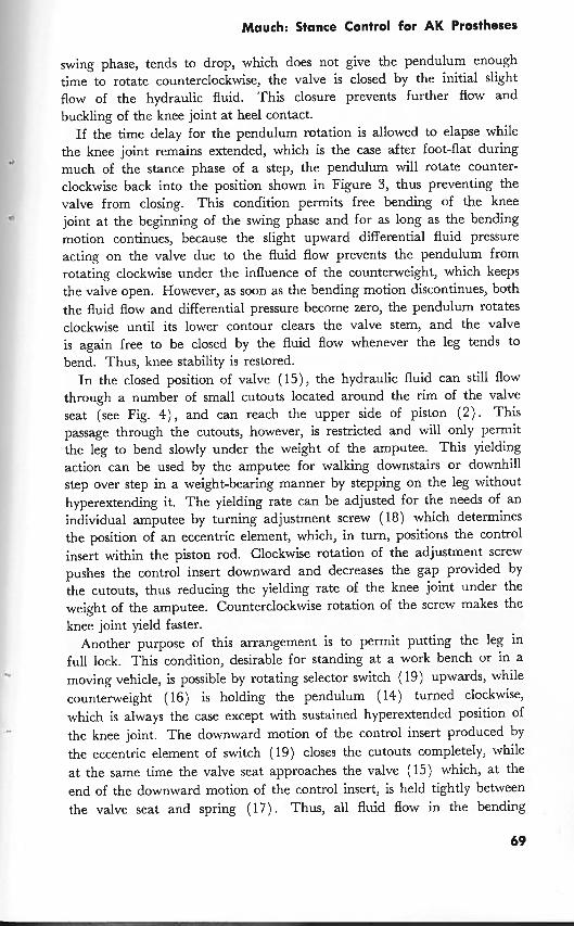
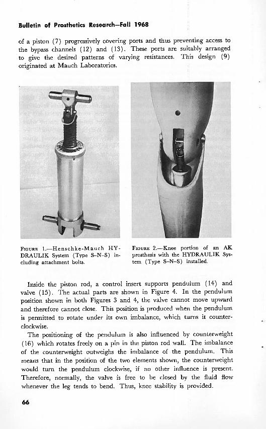
Figure 1 shows the actual hydraulic unit. Figure 2 shows the middle portion of an above-knee prosthesis with the unit installed. Figure 3 shows in schematic form the essential design details inside the hydraulic unit: Piston (2) is attached to piston rod (3) and travels up and down inside cylinder ( 1 ) which is filled with hydraulic fluid (4). Spring-loaded accumulator piston (5) separates the reserve fluid from the working fluid. The accumulator piston travels between the inside wall of cylinder ( 1 ) and the outside wall of dashpot ( 6 ) rising whenever the piston rod is pushed downward, thus providing space for the fluid displaced by the piston rod volume. Parts (7) to (13) provide swing control, using the proven design
Bulletin of Prosthetics Research-Fall 1968
of a piston ( 7 ) progressively covering ports and thus preventing access to the bypass channels (12) and (13). These ports are suitably arranged to give the desired patterns of varying resistances. This design (9) originated at Mauch Laboratories.
FIGURE 1.-Henschke-Mauch H Y - FIGURE 2.-Knee portion of an AK DRAULIK System (Type S-N-S) in- prosthesis with the HYDRAULIK Sys- cluding attachment bolts. tem (Type S-N-S) installed.
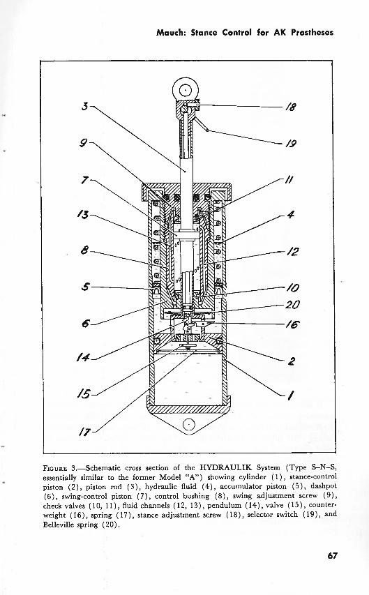
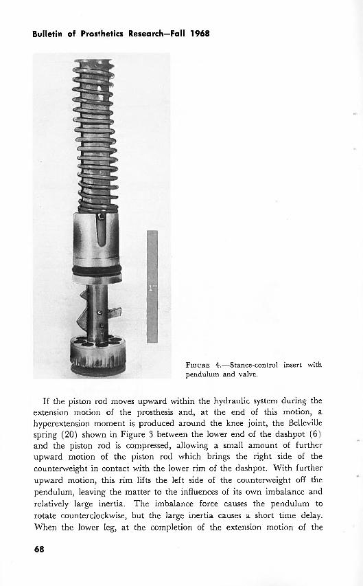
Inside the piston rod, a control insert supports pendulum (14) and valve (15). The actual parts are shown in Figure 4. In the pendulum position shown in both Figures 3 and 4, the valve cannot move upward and therefore cannot close. This position is produced when the pendulum is permitted to rotate under its own imbalance, which turns it counter- clockwise.
The positioning of the pendulum is also influenced by counterweight (16) which rotates freely on a pin in the piston rod wall. The imbalance of the counterweight outweighs the imbalance of the pendulum. This means that in the position of the two elements shown, the counterweight would turn the pendulum clockwise, if no other influence is present. Therefore, normally, the valve is free to be closed by the fluid flow whenever the leg tends to bend. Thus, knee stability is provided.
Mauch: Stance Control for AK Prostheses
FIGURE 3.-Schematic cross section of the HYDRAULIK System (Type S-N-S, essentially similar to the former Model "A") showing cylinder ( I ) , stance-control piston ( 2 ) , piston rod ( 3 ) , hydraulic fluid (4 ) , accumulator piston (5), dashpot (6 ) , swing-control piston ( 7 ) , control bushing (8) , swing adjustment screw (91, check valves ( 10, 11 ) , fluid channels ( 12, 13), pendulum (14), valve (15), counter- weight (16) , spring (17), stance adjustment screw (18), selector switch (19), and Belleville spring (20).
Bulletin of Prosthetics Research-Fall 1968
FIGURE 4.-Stance-control pendulum and valve.
insert with
If the piston rod moves upward within the hydraulic system during the extension motion of the prosthesis and, at the end of this motion, a hyperextension moment is produced around the knee joint, the Belleville spring (20) shown in Figure 3 between the lower end of the dashpot (6) and the piston rod is compressed, allowing a small amount of further upward motion of the piston rod which brings the right side of the counterweight in contact with the lower rim of the dashpot. With further upward motion, this rim lifts the left side of the counterweight off the pendulum, leaving the matter to the influences of its own imbalance and relatively large inertia. The imbalance force causes the pendulum to rotate counterclockwise, but the large inertia causes a short time delay. When the lower leg, at the completion of the extension motion of the