Embed Size (px)
Citation preview
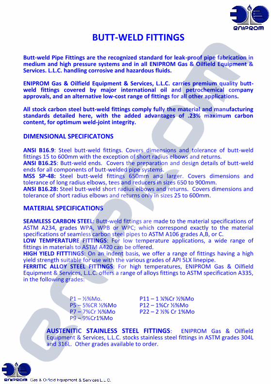
BUTT-WELD FITTINGS
Butt-weld Pipe Fittings are the recognized standard for leak-proof pipe fabrication in medium and high pressure systems and in all ENIPROM Gas & Oilfield Equipment & Services. L.L.C. handling corrosive and hazardous fluids.
ENIPROM Gas & Oilfield Equipment & Services, L.L.C. carries premium quality butt-weld fittings covered by major international oil and petrochemical company approvals, and an alternative low-cost range of fittings for all other applications.
All stock carbon steel butt-weld fittings comply fully the material and manufacturing standards detailed here, with the added advantages of .23% maximum carbon content, for optimum weld-joint integrity.
DIMENSIONAL SPECIFICATONS ANSI B16.9: Steel butt-weld fittings. Covers dimensions and tolerance of butt-weld fittings 15 to 600mm with the exception of short radius elbows and returns. ANSI B16.25: Butt-weld ends. Covers the preparation and design details of butt-weld ends for all components of butt-welded pipe systems. MSS SP-48: Steel butt-weld fittings 650mm and larger. Covers dimensions and tolerance of long radius elbows, tees and reducers in sizes 650 to 900mm. ANSI B16.28: Steel butt-weld short radius elbows and returns. Covers dimensions and tolerance of short radius elbows and returns only in sizes 25 to 600mm. MATERIAL SPECIFICATIONS SEAMLESS CARBON STEEL: Butt-weld fittings are made to the material specifications of ASTM A234, grades WPA, WPB or WPC; which correspond exactly to the material specifications of seamless carbon steel pipes to ASTM A106 grades A,B, or C. LOW TEMPERATURE FITTINGS: For low temperature applications, a wide range of fittings in materials to ASTM A420 can be offered. HIGH YIELD FITTTINGS: On an indent basis, we offer a range of fittings having a high yield strength suitable for use with the various grades of API 5LX linepipe. FERRITIC ALLOY STEEL FITTINGS: For high temperatures, ENIPROM Gas & Oilfield Equipment & Services, L.L.C. offers a range of alloys fittings to ASTM specification A335, in the following grades:
P1 – ½%Mo. P11 – 1 ¼%Cr ½%Mo P5 – 5%CR ½%Mo P12 – 1%Cr ½%Mo P7 – 7%Cr ½%Mo P22 – 2 ½% Cr 1%Mo P9 – 9%Cr1%Mo
AUSTENITIC STAINLESS STEEL FITTINGS: ENIPROM Gas & Oilfield Equipment & Services, L.L.C. stocks stainless steel fittings in ASTM grades 304L and 316L. Other grades available to order.
BUTT-WELD FITTINGS
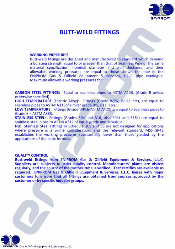
WORKING PRESSURES Butt-weld fittings are designed and manufactured to standard which demand a bursting strength equal to or greater than that of Seamless Pipe of the same material specification, nominal diameter and wall thickness, and their allowable working pressures are equal to those shown for pipe in the ENIPROM Gas & Oilfield Equipment & Services, L.L.C. pipe catalogue. Maximum allowable working pressures for:
CARBON STEEL FITTINGS: Equal to seamless pipes to ASTM A106, (Grade B unless otherwise specified). HIGH TEMPERATURE (Ferritic Alloy): Fittings (Grade WP5, WP11 etc), are equal to seamless pipes to ASTM A335of similar grade (P5, P11, etc). LOW TEMPERATURE: Fittings (Grade WPL6-ASTM A420) are equal to seamless pipes to Grade 6 – ASTM A333. STAINLESS STEEL: Fittings (Grades 304 and 316, also 304L and 316L) are equal to stainless steel pipes to ASTM A312 of equal grade and schedule. NB: Stainless Steel Fittings in Schedule 10S and 5S are not designed for applications where pressure is a prime consideration, and the relevant standard, MSS SP43 establishes the working pressures substantially lower than those yielded by the applications of the basic formula. QUALITY CONTROL Butt-weld fittings from ENIPROM Gas & Oilfield Equipment & Services. L.L.C. Suppliers are subjects to strict quality control. Manufacturers’ plants are visited regularly, and the source of the mother tube is verified. Test certifies are available as required. ENIPROM Gas & Oilfield Equipment & Services, L.L.C. liaises with major customers to ensure that all fittings are obtained from sources approved by the customer or by specific industry groups.
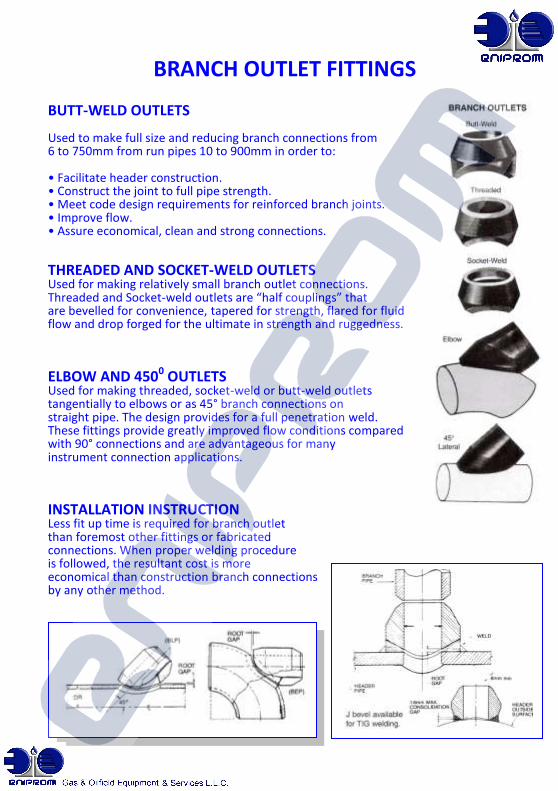
BRANCH OUTLET FITTINGS BUTT-WELD OUTLETS Used to make full size and reducing branch connections from 6 to 750mm from run pipes 10 to 900mm in order to: • Facilitate header construction. • Construct the joint to full pipe strength. • Meet code design requirements for reinforced branch joints. • Improve flow. • Assure economical, clean and strong connections. THREADED AND SOCKET-WELD OUTLETS Used for making relatively small branch outlet connections. Threaded and Socket-weld outlets are “half couplings” that are bevelled for convenience, tapered for strength, flared for fluid flow and drop forged for the ultimate in strength and ruggedness. ELBOW AND 4500 OUTLETS Used for making threaded, socket-weld or butt-weld outlets tangentially to elbows or as 45° branch connections on straight pipe. The design provides for a full penetration weld. These fittings provide greatly improved flow conditions compared with 90° connections and are advantageous for many instrument connection applications.
INSTALLATION INSTRUCTION Less fit up time is required for branch outlet than foremost other fittings or fabricated connections. When proper welding procedure is followed, the resultant cost is more economical than construction branch connections by any other method.
HIGH PRESSURE FITTINGS SCREWED & SOCKET-WELD 2000, 3000 & 6000 lb
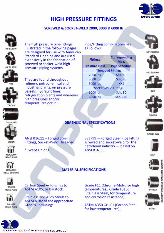
The high pressure pipe fittings Pipe/Fitting combinations are illustrated in the following pages as Follows: are designed for use with American Standard Linepipe and are used extensively in the fabrication of screwed or socket-weld high pressure piping systems. They are found throughout refinery, petrochemical and industrial plants, on pressure vessels, hydraulic lines, refrigeration plants and wherever high pressures and/or temperatures occur.
DIMENSIONAL SPECIFICATIONS
ANSI B16.11 – Forged Steel BS3799 —Forged Steel Pipe Fittings Fittings, Socket-Weld Threaded screwed and socket-weld for the petroleum industry — based on *Except Unions ANSI B16.11
MATERIAL SPECIFICATIONS
Carbon Steel — forgings to Grade F11 (Chrome-Moly, for high ASTM A105, or Barstock. temperatures), Grade F316L (Stainless Steel, for temperature Stainless and Alloy Steels to and corrosion resistance). ASTM A182 of the appropriate Grades, including:— ASTM A350 Gr-LF1 (Carbon Steel for low temperatures).
Fittings Corresponding
Max. Pressure Class Pipe Schedule
Threaded Fittings 2000 lbs Sch. 40 3000 lbs Sch. 80 6000 lbs XXS
Socket-Weld Fittings 3000 lbs Sch. 80 6000 lbs Sch. 160
HIGH PRESSURE FITTINGS
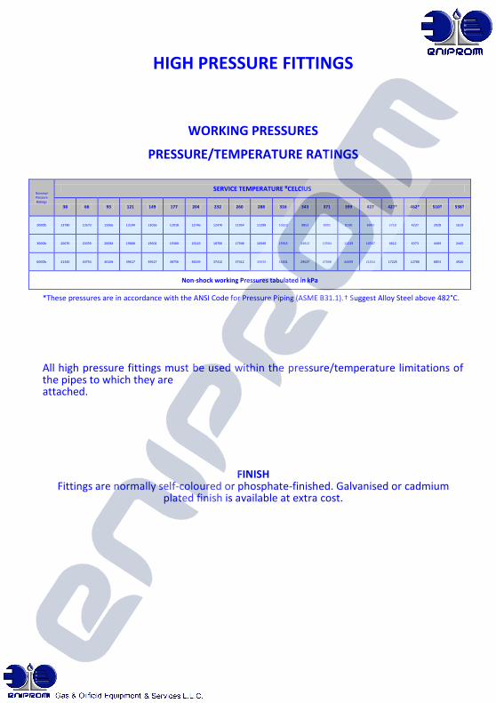
WORKING PRESSURES
PRESSURE/TEMPERATURE RATINGS
*These pressures are in accordance with the ANSI Code for Pressure Piping (ASME B31.1).† Suggest Alloy Steel above 482°C.
All high pressure fittings must be used within the pressure/temperature limitations of the pipes to which they are attached.
FINISH Fittings are normally self-coloured or phosphate-finished. Galvanised or cadmium
plated finish is available at extra cost.
Nominal Pressure Ratings
SERVICE TEMPERATURE ⁰CELCIUS
38 66 93 121 149 177 204 232 260 288 316 343 371 399 427 427* 482* 510† 538†
2000lb 13780 13573 13366 13194 13056 12918 12746 12470 11954 11299 10610 9852 8991 8130 6993 5718 4237 2928 1619
3000lb 20670 20359 20084 19808 19602 19360 19119 18706 17948 16949 15915 14813 13504 12229 10507 8612 6373 4409 2445
6000lb 41340 40754 40168 39617 39617 38756 38239 37412 37412 33933 31831 29627 27008 24459 21014 17225 12780 8853 4926
Non-shock working Pressures tabulated in kPa
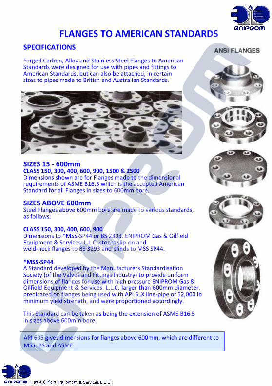
FLANGES TO AMERICAN STANDARDS SPECIFICATIONS Forged Carbon, Alloy and Stainless Steel Flanges to American Standards were designed for use with pipes and fittings to American Standards, but can also be attached, in certain sizes to pipes made to British and Australian Standards. SIZES 15 - 600mm CLASS 150, 300, 400, 600, 900, 1500 & 2500 Dimensions shown are for Flanges made to the dimensional requirements of ASME B16.5 which is the accepted American Standard for all Flanges in sizes to 600mm bore. SIZES ABOVE 600mm Steel Flanges above 600mm bore are made to various standards, as follows: CLASS 150, 300, 400, 600, 900 Dimensions to *MSS-SP44 or BS 2393. ENIPROM Gas & Oilfield Equipment & Services. L.L.C. stocks slip-on and weld-neck flanges to BS 3293 and blinds to MSS SP44. *MSS-SP44 A Standard developed by the Manufacturers Standardisation Society (of the Valves and Fittings Industry) to provide uniform dimensions of flanges for use with high pressure ENIPROM Gas & Oilfield Equipment & Services. L.L.C. larger than 600mm diameter. These designs were predicated on flanges being used with API 5LX line-pipe of 52,000 lbs. minimum yield strength, and were proportioned accordingly. This Standard can be taken as being the extension of ASME B16.5 in sizes above 600mm bore.
API 605 gives dimensions for flanges above 600mm, which are different to MSS, BS and ASME.
FLANGES TO AMERICAN STANDARDS
LARGE DIAMETER FLANGE STANDARDS
ASME B16.1B This Standard establishes dimensions for Class 250 Cast Iron Flanges above 600mm, (as ANSI B16.1 gives dimensions for large diameter Class 125 Cast Iron Flanges). API 605 American Petroleum Institute Standard intended primarily for use in Oil and Gas production. API 605 dimensions DO NOT match ANSI, MSS or BS dimensions of similar pressure class. AWWA C207-54T This is a Standard published by the American Waterworks Association for steel Flanges to be used on waterworks and sewerage pipes. These flanges match Class 125 Cast Iron Flanges (ANSI B16.1) in most dimensions. CLASSES 125LW, 175 & 350 These are Standards developed over the years by a number of manufacturers, not all using exactly the same dimensions. TEMA FLANGES The Tubular Exchangers Manufacturers Association (TEMA) lays down standards for dimensions and material specifications for Shell Flanges, Cover Flanges, Long Welding Necks for Nozzles and other heat exchanger components. BS.3293 This British Standard established dimensions for flanges for petroleum industry use, in Class 150, 300, 400 and 600, in sizes above 600mm, which correspond exactly to those of MSS SP-44 in Class 300, 400 and 600. Class 900 is not included in the British Standard, but dimensions are given for Class 150, 600-700mm which are similar to those of ANSI B16.1, Class 125. BS.1560 This British Standard is based on ANSI B16.5, and lists Steel Pipe Flanges to the same dimensions, pressure classes and in the same sizes as the American Standard up to 600
FLANGES TO AMERICAN STANDARDS
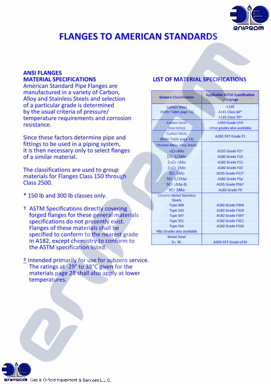
ANSI FLANGES MATERIAL SPECIFICATIONS LIST OF MATERIAL SPECIFICATIONS American Standard Pipe Flanges are manufactured in a variety of Carbon, Alloy and Stainless Steels and selection of a particular grade is determined by the usual criteria of pressure/ temperature requirements and corrosion resistance. Since these factors determine pipe and fittings to be used in a piping system, it is then necessary only to select flanges of a similar material. The classifications are used to group materials for Flanges Class 150 through Class 2500. * 150 lb and 300 lb classes only. † ASTM Specifications directly covering forged flanges for these general materials specifications do not presently exist. Flanges of these materials shall be specified to conform to the nearest grade in A182, except chemistry to conform to the ASTM specification listed. † Intended primarily for use for subzero service. The ratings at -29° to 38°C given for the materials page 28 shall also apply at lower temperatures.
General Classification Applicable ASTM Specification
- Forgings
Carbon Steel (Refer Table page 13)
A105
A181 Class 60*
A181 Class 70†
Carbon Steel A350 Grade LFI‡
(low temp) other grades also available
Carbon Moly A182-55T Grade F1
(Refer Table page 13)
Chrome-Moly Alloy Steels
½Cr½Mo A335 Grade P2†
1Cr 1/2Mo A182 Grade F12
1¼Cr ½Mo A182 Grade F11
2¼Cr 1Mo A182 Grade F22
3Cr 1Mo A335 Grade P21†
5Cr 1/2Mo A182 Grade F5a
5Cr ½Mo-Si A335 Grade P5b†
9Cr 1Mo A182 Grade F9
Chrome-Nickel Stainless Steels
Type 304 A182 Grade F304
Type 310 A182 Grade F310
Type 347 A182 Grade F347
Type 321 A182 Grade F321
Type 316 A182 Grade F316
H&L Grades also available
Nickel Steel
3½ Ni. A350-55T Grade LF3‡
FLANGES TO AMERICAN STANDARDS
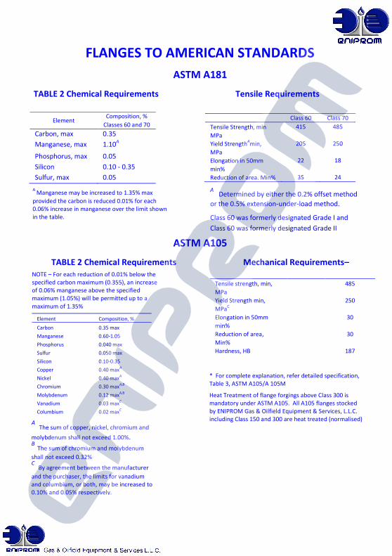
ASTM A181 TABLE 2 Chemical Requirements Tensile Requirements
ASTM A105
TABLE 2 Chemical Requirements Mechanical Requirements–
nominal*
A Manganese may be increased to 1.35% max
provided the carbon is reduced 0.01% for each 0.06% increase in manganese over the limit shown in the table.
NOTE – For each reduction of 0.01% below the specified carbon maximum (0.355), an increase of 0.06% manganese above the specified maximum (1.05%) will be permitted up to a maximum of 1.35%
A The sum of copper, nickel, chromium and
molybdenum shall not exceed 1.00%. B
The sum of chromium and molybdenum
shall not exceed 0.32% C
By agreement between the manufacturer
and the purchaser, the limits for vanadium and columbium, or both, may be increased to 0.10% and 0.05% respectively.
Element Composition, %
Classes 60 and 70
Carbon, max 0.35
Manganese, max 1.10A
Phosphorus, max 0.05
Silicon 0.10 - 0.35
Sulfur, max 0.05
Element Composition, %
Carbon 0.35 max
Manganese 0.60-1.05
Phosphorus 0.040 max
Sulfur 0.050 max
Silicon 0.10-0.35
Copper 0.40 maxA
Nickel 0.40 maxA
Chromium 0.30 maxA,B
Molybdenum 0.12 maxA,B
Vanadium 0.03 maxC
Columbium 0.02 maxC
Class 60 Class 70
Tensile Strength, min 415 485
MPa
Yield StrengthAmin, 205 250
MPa
Elongation in 50mm 22 18
min%
Reduction of area. Min% 35 24
A Determined by either the 0.2% offset method
or the 0.5% extension-under-load method.
Class 60 was formerly designated Grade I and
Class 60 was formerly designated Grade II
* For complete explanation, refer detailed specification, Table 3, ASTM A105/A 105M
Heat Treatment of flange forgings above Class 300 is mandatory under ASTM A105. All A105 flanges stocked by ENIPROM Gas & Oilfield Equipment & Services, L.L.C. including Class 150 and 300 are heat treated (normalised)
Tensile strength, min,
485
MPa Yield Strength min,
250
MPaC Elongation in 50mm
30
min% Reduction of area,
30
Min% Hardness, HB
187
max
FLANGES TO AMERICAN STANDARDS
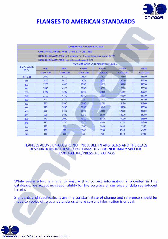
FLANGES ABOVE DN 600 ARE NOT INCLUDED IN ANSI B16.5 AND THE CLASS DESIGNATIONS IN THESE LARGE DIAMETERS DO NOT IMPLY SPECIFIC
TEMPERATURE/PRESSURE RATINGS
While every effort is made to ensure that correct information is provided in this catalogue, we accept no responsibility for the accuracy or currency of data reproduced herein. Standards and specifications are in a constant state of change and reference should be made to copies of relevant standards where current information is critical.
TEMPERATURE / PRESSURE RATINGS
CARBON STEEL PIPE FLANGES TO ANSI B16.5 (BS. 1560)
FORGINGS TO ASTM A105 - Not recommended for prolonged use above 427⁰C
FORGINGS TO ASTM A350 - Not to be used above 343⁰C
TEMPERATURE IN ⁰C
MAXIMIM WORKING PRESSURE IN kPa BY PN
PN20 PN50 PN100 PN150 PN250 PN420
CLASS 150 CLASS 300 CLASS 600 CLASS 900 CLASS 1500 CLASS 2500
-29 to 38 1960 5110 10210 15320 25530 42550
50 1920 5010 10020 15020 25040 41730
100 1770 4640 9280 13910 23190 38650
150 1580 4520 9050 13570 22610 37690
200 1400 4380 8760 13150 21910 36520
250 1210 4170 8340 12520 20860 34770
300 1020 3870 7750 11620 19370 32280
350 840 3700 7390 11090 18480 30800
375 740 3650 7290 10940 18230 30390
400 650 3450 6900 10350 17250 28750
425 560 2880 5750 8630 14380 23960
450 470 2000 4010 6010 10020 16690
475 370 1350 2710 4060 6770 11290
500 280 880 1760 2640 4400 7330
525 190 520 1040 1550 2590 4320
540 130 330 650 980 1630 2720

FLANGES TO AMERICAN STANDARDS BOLTING To suit R.F. Flange sizes DN 15 to 600 to ASME — B16.5 (BS. 1560) and DN 750 & 900 to BS. 3293
Diameter of Bolts is shown in inches. For nominal diameters 1 inch and smaller, threads are U.N.C.; nominal diameters 1-1/8 inch and larger threads are 8 U.N. (8 T.P.I.). Length of Bolts (L) is shown in millimetres rounded to the nearest 5 mm. Stud Bolt lengths (L*) do not include the height of points. Machine Bolt lengths (L) include the height of point. The length shown includes the height of the Raised Face in all cases.
FLANGES TO AMERICAN STANDARDS
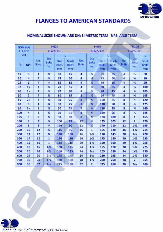
NOMINAL SIZES SHOWN ARE DN: SI METRIC TERM NPS: ANSI TERM
NOMINAL FLANGE
SIZE
PN20 PN50 PN100
CLASS 150 CLASS 300 CLASS 600
No. Bolts
Dia Bolts ins.
L
No. Bolts
Dia Bolts ins.
L
No. Bolts
Dia Bolts ins.
L
DN NPS Stud Bolts mm
Mach Bolts mm
Stud Bolts mm
Mach Bolts mm
Stud Bolts mm
15 ½ 4 ½ 60 45 4 ½ 65 55 4 ½ 80
20 ¾ 4 ½ 65 50 4 ⅝ 75 60 4 ⅝ 90
25 1 4 ½ 65 55 4 ⅝ 80 65 4 ⅝ 90
32 1¼ 4 ½ 70 55 4 ⅝ 80 65 4 ⅝ 100
40 1½ 4 ½ 70 60 4 ¾ 90 75 4 ¾ 105
50 2 4 ⅝ 80 65 8 ⅝ 90 75 8 ⅝ 105
65 2½ 4 ⅝ 90 75 8 ¾ 100 85 8 ¾ 120
80 3 4 ⅝ 90 75 8 ¾ 110 90 8 ¾ 125
90 3½ 8 ⅝ 90 75 8 ¾ 110 95 8 ⅞ 140
100 4 8 ⅝ 90 75 8 ¾ 110 95 8 ⅞ 145
125 5 8 ¾ 90 80 8 ¾ 120 100 8 1 165
150 6 8 ¾ 100 85 12 ¾ 125 105 12 1 170
200 8 8 ¾ 110 90 12 ⅞ 140 110 12 1-⅛ 195
250 10 12 ⅞ 115 95 16 1 155 130 16 1-¼ 215
300 12 12 ⅞ 120 100 16 1-⅛ 170 145 20 1-¼ 220
350 14 12 1 130 110 20 1-⅛ 175 150 20 1-⅜ 235
400 16 16 1 135 115 20 1-¼ 190 160 20 1-½ 255
450 18 16 1-⅛ 150 125 24 1-¼ 195 170 20 1-⅝ 275
500 20 20 1-⅛ 160 135 24 1-¼ 205 180 24 1-⅝ 290
600 24 20 1-¼ 175 145 24 1-½ 230 195 24 1-⅞ 330
750 30 28 1-¼ 190 160 28 1-¾ 290 250 28 2 355
900 36 32 1-½ 215 180 32 2 325 280 28 2-½ 400
FLANGES TO AMERICAN STANDARDS
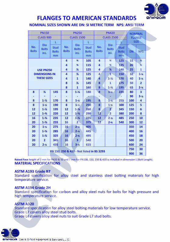
NOMINAL SIZES SHOWN ARE DN: SI METRIC TERM NPS: ANSI TERM
Raised Face height of 2 mm for PN20 & 50 and 7 mm for PN100, 150, 250 & 420 is included in dimension L (Bolt Length).
MATERIAL SPECIFICATIONS ASTM A193 Grade B7 Standard specification for alloy steel and stainless steel bolting materials for high temperature service. ASTM A194 Grade 2H Standard specification for carbon and alloy steel nuts for bolts for high pressure and high temperature service. ASTM A320 Standard specification for alloy steel bolting materials for low temperature service. Grade L7 covers alloy steel stud bolts. Grade L4 covers alloy steel nuts to suit Grade L7 stud bolts.
PN150 PN250 PN420 NOMINAL FLANGE
SIZE
CLASS 900 CLASS 1500 CLASS 2500
No. Bolts
Dia Bolts ins.
L
No. Bolts
Dia Bolts ins.
L
No. Bolts
Dia Bolts ins.
L
Stud Bolts mm
Stud Bolts mm
Stud Bolts mm
DN NPS
USE PN250 DIMENSIONS IN
THESE SIZES
4 ¾ 105 4 ¾ 125 15 ½
4 ¾ 115 4 ¾ 125 20 ¾
4 ⅞ 125 4 ⅞ 140 25 1
4 ⅞ 125 4 1 150 32 1-¼
4 1 140 4 1-⅛ 170 40 1-½
8 ⅞ 145 8 1 175 50 2
8 1 160 8 1-⅛ 195 65 2-½
8 ⅞ 145 8 1-⅛ 180 8 1-¼ 220 80 3
- - - - - - - - - 90 3-½
8 1-⅛ 170 8 1-¼ 195 8 1-½ 255 100 4
8 1-¼ 190 8 1-½ 250 8 1-¾ 300 125 5
12 1-⅛ 195 12 1-⅜ 260 8 2 345 150 6
12 1-⅜ 220 12 1-⅝ 290 12 2 380 200 8
16 1-⅜ 235 12 1-⅞ 335 12 2-½ 485 250 10
20 1-⅜ 255 16 2 375 12 2-¾ 540 300 12
20 1-½ 275 16 2-¼ 405
350 14
20 1-⅝ 285 16 2-½ 445 400 16
20 1-⅞ 325 16 2-¾ 495 450 18
20 2 345 16 3 540 500 20
20 2-½ 435 16 3-½ 615 600 24
PN 150, 250 & 420 - Not listed in BS 3293 750 30
900 36
FLANGES TO AMERICAN STANDARDS
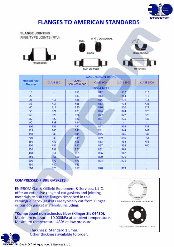
COMPRESSED FIBRE GASKETS ENIPROM Gas & Oilfield Equipment & Services, L.L.C. offer an extensive range of cut gaskets and jointing materials to suit the flanges described in this catalogue. Stock gaskets are typically cut from Klinger or Garlock gasket materials, including: *Compressed non-asbestos fiber (Klinger SIL C4430). Maximum pressure: 10,000kPa at ambient temperature. Maximum temperature: 430⁰ at low pressure. Thickness: Standard 1.5mm. Other thickness available to order.
Nominal Pipe Size mm
FLANGE PRESSURE RATING
CLASS 150 CLASS
300, 400 & 600 CLASS 900 CLASS 1500 CLASS 2500
RING NUMBER
15 - R11 R12 R12 R13
20 - R13 R14 R14 R16
25 R15 R16 R16 R16 R18
32 R17 R18 R18 R18 R21
40 R19 R20 R20 R20 R23
50 R22 R23 R24 R24 R26
65 R25 R26 R27 R27 R28
80 R29 R31 R31 R35 R32
90 R33 R34 - - -
100 R36 R37 R37 R39 R38
125 R40 R41 R41 R44 R42
150 R43 R45 R45 R46 R47
200 R48 R49 R49 R50 R51
250 R52 R53 R53 R54 R55
300 R56 R57 R57 R58 R60
350 R59 R61 R62 R63 -
400 R64 R65 R66 R67 -
450 R68 R69 R70 R71 -
500 R72 R73 R74 R75 -
550 R80 R81 - - -
600 R76 R77 R78 R79 -
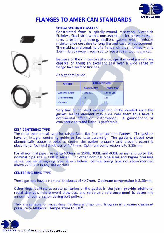
FLANGES TO AMERICAN STANDARDS SPIRAL WOUND GASKETS Constructed from a spirally-wound V-section Austenitic Stainless Steel strip with a non-asbestos filler between each turn, providing a strong, resilient gasket which reduces maintenance cost due to long life and ease of replacement. The making and breaking of a flange joint is simplified – only 1.6mm breakaway is required to free a spiral-wound gasket. Because of their in built-resilience, spiral wound gaskets are capable of giving an excellent seal over a wide range of flange face surface finishes. As a general guide: Very fine or polished surfaces should be avoided since the gasket sealing element may slide over them thus have a detrimental effect on performance. A gramophone or concentric serrated finish is preferable.
SELF-CENTERING TYPE The most economical type for raised-face, flat face or lap-joint flanges. The gaskets have an integral centering guide to facilitate assembly. The guide is placed over diametrically opposite bolts to center the gasket properly and prevent eccentric placement. Nominal thickness of 4.47mm. Optimum compression is to 3.25mm. For all nominal pipe size up to 600mm in 150lb, 300lb and 400lb series; and up to 150 nominal pipe size in 600 lb series. For other nominal pipe sizes and higher pressure series, use centering-ring type shown below. Self-centering type not recommended above 2758 kPa in any size or class. CENTERING-RING TYPE These gaskets have a nominal thickness of 4.47mm. Optimum compression is 3.25mm. Other rings facilitate accurate centering of the gasket in the joint, provide additional radial strength, help prevent blow-out, and serve as a reference point to determine amount of compression during bolt pull-up. They are suitable for raised-face, flat-face and lap-joint flanges in all pressure classes at pressure to 6895kPa. Temperature to 538⁰C.
SERVICE SURFACE FINISH
Micro Metre Micro Inch
General duties 3.2 to 5.1 125 to 200
Critical duties 3.2 125
Vacuum 2 80