Embed Size (px)
Citation preview
RESEARCH&DEVELOPMENT OF AMERICA, INC.
www.yoshimura-rd.com
RS-5 PERFORMANCE EXHAUST SYSTEM
122602(2,5,7) STAINLESS STEEL FULL SYSTEM
122607(2,5,7) STAINLESS STEEL FULL SYSTEM WITH CONE CAP
NOTE: IN THE STATE OF CALIFORNIA, IT IS ILLEGAL TO MODIFY THE EMISSION CONTROL SYSTEM, WHICH INCLUDES THE CARBURETORS OF ANY VEHICLE.
5420 DANIELS STREET STE A, CHINO CA. 91786 · (800)634-9166 · (909)628-4722 · FACSIMILE (909)591-2198
THIS PRODUCT IS DESIGNED FOR USE IN CLOSED COURSE RACING AND IS NOT INTENDED FOR HIGHWAY USE.! !
HONDA2005-2006CBR600RR
Caution: Exhaust system can be extremely hot. Let motorcycle cool down before beginning installation.
Note: Read through all instructions before beginning installation.
Installation Steps:
Tools Needed:
8mm, 10mm, and 12mm socketsRatchet10mm and 12mm wrench5mm and 8mm Allen wrenchTorque wrenchSharp Scissors
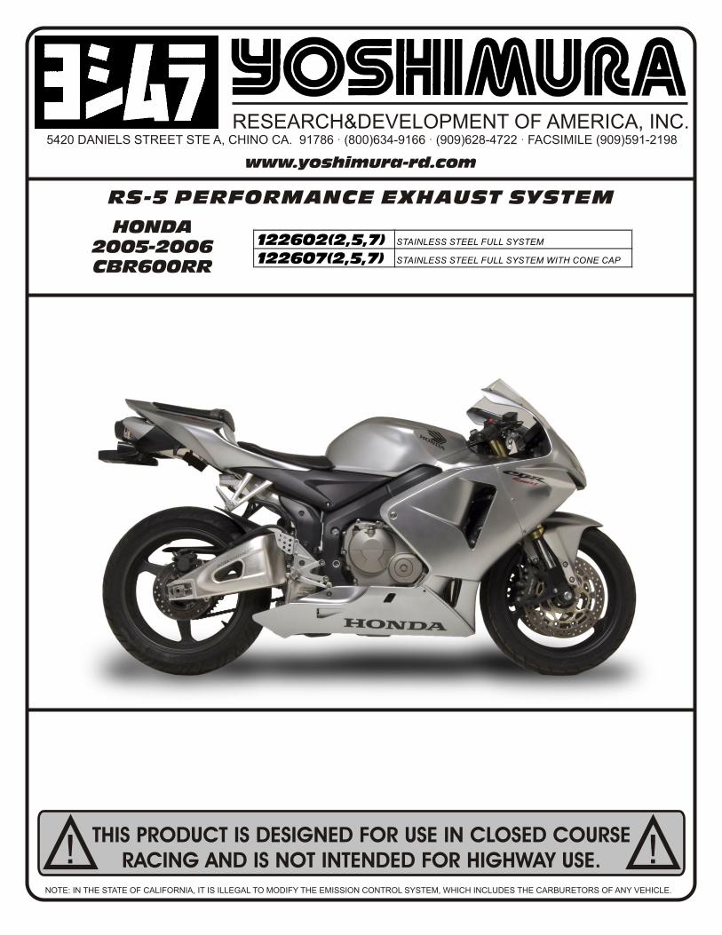
1Remove rider seat (2 bolts under rear edges of seat) and passenger seat.
2Remove right and left side black plastic tank side panels (remove top and side bolts and upper and lower plastic fasteners. Pull front out to unclip and pull toward front of bike to remove) (See Fig. 1).
3Remove seat cowling: Remove 4 bolts (See Fig. 1), pull cowling toward rear of bike and up. Disconnect tail light connector and remove cowling.
4Unbolt black plastic heatshield and right side footpeg assembly. (See Fig. 2) Move footpeg assembly out of the way.
5 Remove metal heatshield (right passenger footrest must be removed in order to remove the last bolt).
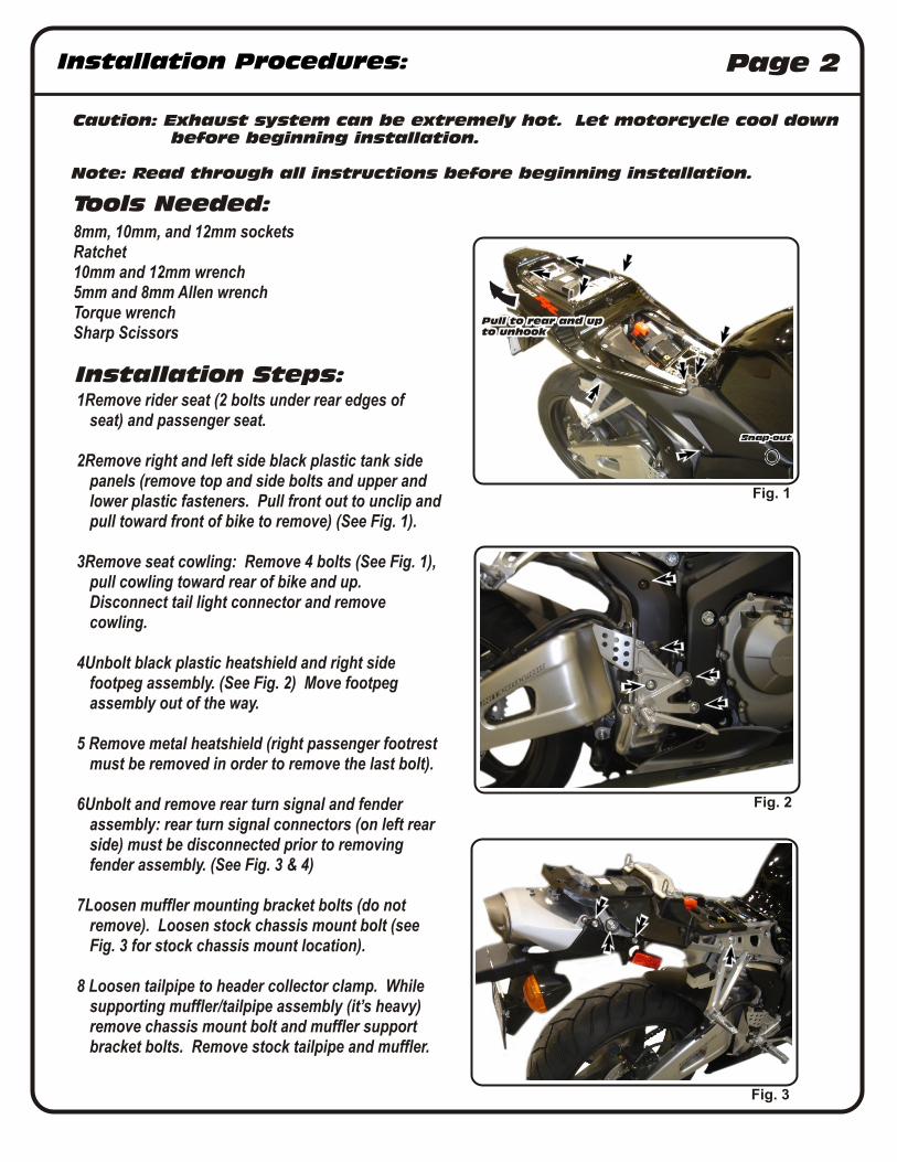
6Unbolt and remove rear turn signal and fender assembly: rear turn signal connectors (on left rear side) must be disconnected prior to removing fender assembly. (See Fig. 3 & 4)
7Loosen muffler mounting bracket bolts (do not remove). Loosen stock chassis mount bolt (see Fig. 3 for stock chassis mount location).
8 Loosen tailpipe to header collector clamp. While supporting muffler/tailpipe assembly (it’s heavy) remove chassis mount bolt and muffler support bracket bolts. Remove stock tailpipe and muffler.
Fig. 3
Fig. 1
Fig. 2
Installation Procedures: Page 2
Pull to rear and upto unhook
Installation Procedures: Page 3
Fig. 5
Fig. 4
Disconnect 3 connectors
Looking at Front of Engine
Arrows show spring locations
9 Remove stock heatshield. (Note: Stock heatshield will not be used with Yoshimura system.
10 Install adhesive heatshield to rear undertail section. (See page 5 for instructions)
11 Remove lower cowling.
12 Remove front right and front left cowling.
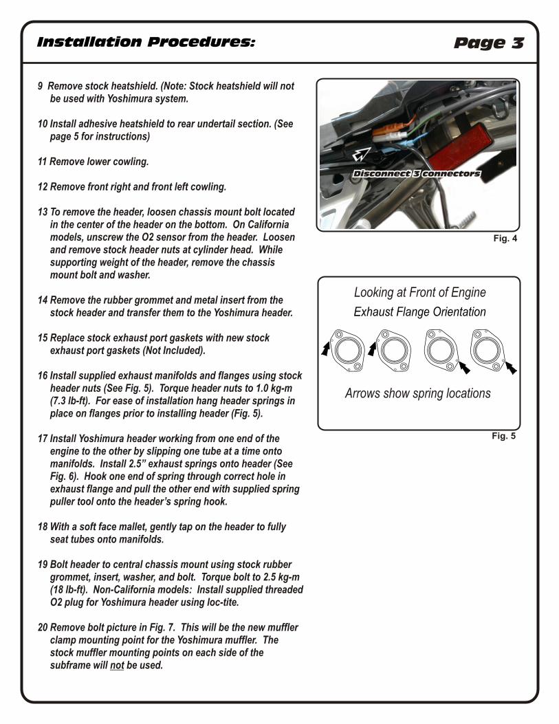
13 To remove the header, loosen chassis mount bolt located in the center of the header on the bottom. On California models, unscrew the O2 sensor from the header. Loosen and remove stock header nuts at cylinder head. While supporting weight of the header, remove the chassis mount bolt and washer.
14 Remove the rubber grommet and metal insert from the stock header and transfer them to the Yoshimura header.
15 Replace stock exhaust port gaskets with new stock exhaust port gaskets (Not Included).
16 Install supplied exhaust manifolds and flanges using stock header nuts (See Fig. 5). Torque header nuts to 1.0 kg-m (7.3 lb-ft). For ease of installation hang header springs in place on flanges prior to installing header (Fig. 5).
17 Install Yoshimura header working from one end of the engine to the other by slipping one tube at a time onto manifolds. Install 2.5” exhaust springs onto header (See Fig. 6). Hook one end of spring through correct hole in exhaust flange and pull the other end with supplied spring puller tool onto the header’s spring hook.
18 With a soft face mallet, gently tap on the header to fully seat tubes onto manifolds.
19 Bolt header to central chassis mount using stock rubber grommet, insert, washer, and bolt. Torque bolt to 2.5 kg-m (18 lb-ft). Non-California models: Install supplied threaded O2 plug for Yoshimura header using loc-tite.
20 Remove bolt picture in Fig. 7. This will be the new muffler clamp mounting point for the Yoshimura muffler. The stock muffler mounting points on each side of the subframe will not be used.

Installation Procedures: Page 4
20 Install Yoshimura tailpipe with muffler onto Yoshimura header. Install stock chassis mount bolt loosely to hold tailpipe in place. Connect tailpipe to header with supplied springs.
21 Install supplied muffler clamp heat insulator to inside of muffler clamp. Slide muffler clamp onto muffler and line up muffler clamp ears with new muffler mount location. Bolt the right side of the clamp to the subframe with the supplied bolt. Slide left side of muffler clamp over the protruding bolt and install the supplied nut (see Fig. 8).
22Check alignment of exhaust, then torque stock collector clamp to 1.25 kg-m (9 lb-ft).
23Torque muffler clamp bolt and nut to 2.5 kg-m (18 lb-ft).
24Torque chassis mount bolt to 1.25 kg-m (9 lb-ft).
25It is recommended that the muffler, tailpipe and header be wiped down with rubbing alcohol to remove oil and fingerprints. This will help prevent tarnishing of the finish after the exhaust is heated up.
26 Re-install tailpipe heat shield, rear fender, rear cowling, foot peg, and seat in reverse order of disassembly. Check for proper operation of tail light, brake light, and turn signals before completion.
27Re-install front upper and lower cowlings.
28Check for proper clearance between new exhaust system and motorcycle. (i.e. Swing-arm, body work, etc.) If any problem is found, please carefully follow through the installation steps again. If problem still persists, please call Yoshimura tech. dept. at(800)634-9166 / in CA (909)628-4722.
NOTE: After starting motorcycle, it is normal for new exhaust system and muffler to smoke until oil residue burns off.
Fig.7
Fig. 6
Installation Procedures: Page 5
Fig. 9
Fig. 10
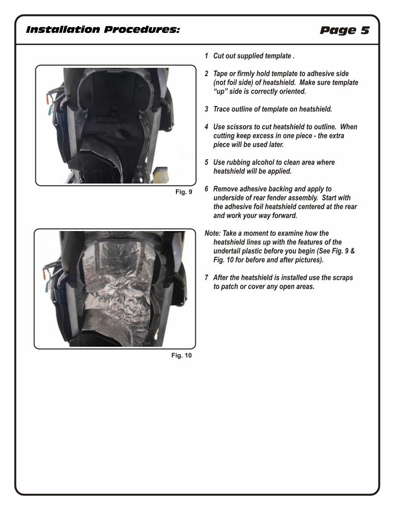
1 Cut out supplied template .
2 Tape or firmly hold template to adhesive side (not foil side) of heatshield. Make sure template “up” side is correctly oriented.
3 Trace outline of template on heatshield.
4 Use scissors to cut heatshield to outline. When cutting keep excess in one piece - the extra piece will be used later.
5 Use rubbing alcohol to clean area where heatshield will be applied.
6 Remove adhesive backing and apply to underside of rear fender assembly. Start with the adhesive foil heatshield centered at the rear and work your way forward.
Note: Take a moment to examine how the heatshield lines up with the features of the undertail plastic before you begin (See Fig. 9 & Fig. 10 for before and after pictures).
7 After the heatshield is installed use the scraps to patch or cover any open areas.
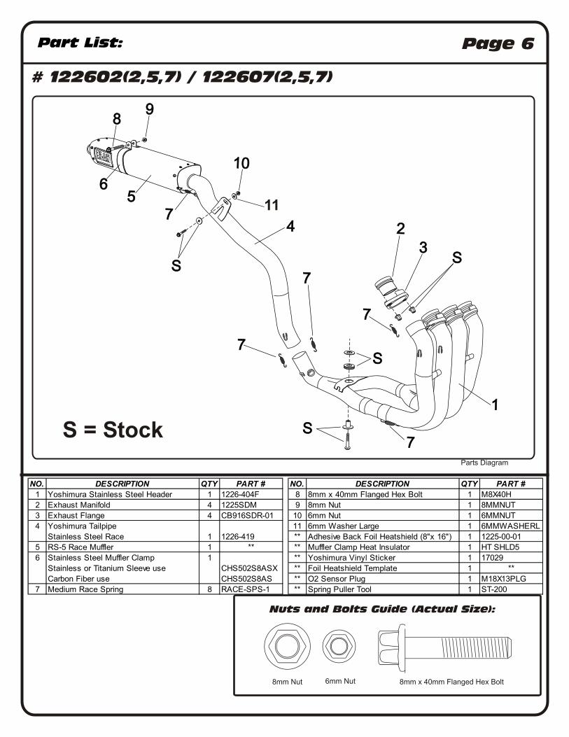
NO. DESCRIPTION QTY PART # NO. DESCRIPTION QTY PART #
1 Yoshimura Stainless Steel Header 1 1226-404F 8 8mm x 40mm Flanged Hex Bolt 1 M8X40H
2 Exhaust Manifold 4 1225SDM 9 8mm Nut 1 8MMNUT
3 Exhaust Flange 4 CB916SDR-01 10 6mm Nut 1 6MMNUT
4 Yoshimura Tailpipe 11 6mm Washer Large 1 6MMWASHERL
Stainless Steel Race 1 1226-419 ** Adhesive Back Foil Heatshield (8"x 16") 1 1225-00-01
5 RS-5 Race Muffler 1 ** ** Muffler Clamp Heat Insulator 1 HT SHLD5
6 Stainless Steel Muffler Clamp 1 ** Yoshimura Vinyl Sticker 1 17029
Stainless or Titanium Sleeve use CHS502S8ASX ** Foil Heatshield Template 1 **
Carbon Fiber use CHS502S8AS ** O2 Sensor Plug 1 M18X13PLG
7 Medium Race Spring 8 RACE-SPS-1 ** Spring Puller Tool 1 ST-200
Part List: Page 6
# 122602(2,5,7) / 122607(2,5,7)
Parts Diagram
Nuts and Bolts Guide (Actual Size):
6mm Nut8mm Nut 8mm x 40mm Flanged Hex Bolt
SSS
SSS
SSS
222333
777
777
777
777555
666
777
111
444
SSS
888999
111000
S = Stock
11