Embed Size (px)
Citation preview
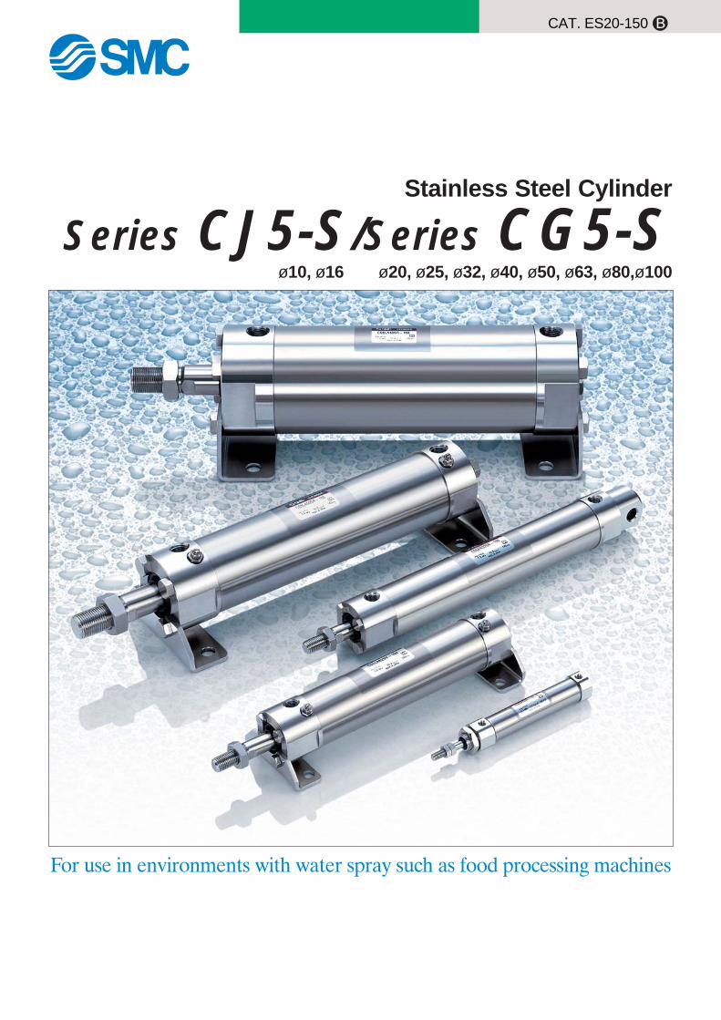
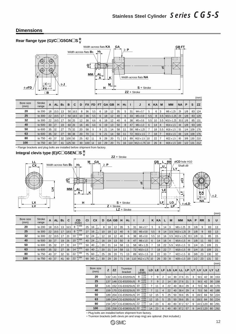
Stainless Steel Cylinder
Series CJ5-S/Series CG5-S
CAT. ES20-150 B
For use in environments with water spray such as food processing machines
ø10, ø16 ø20, ø25, ø32, ø40, ø50, ø63, ø80,ø100
ø10, ø16 ø20, ø25, ø32, ø40, ø50, ø63, ø80, ø100
Stainless Steel Cylinder
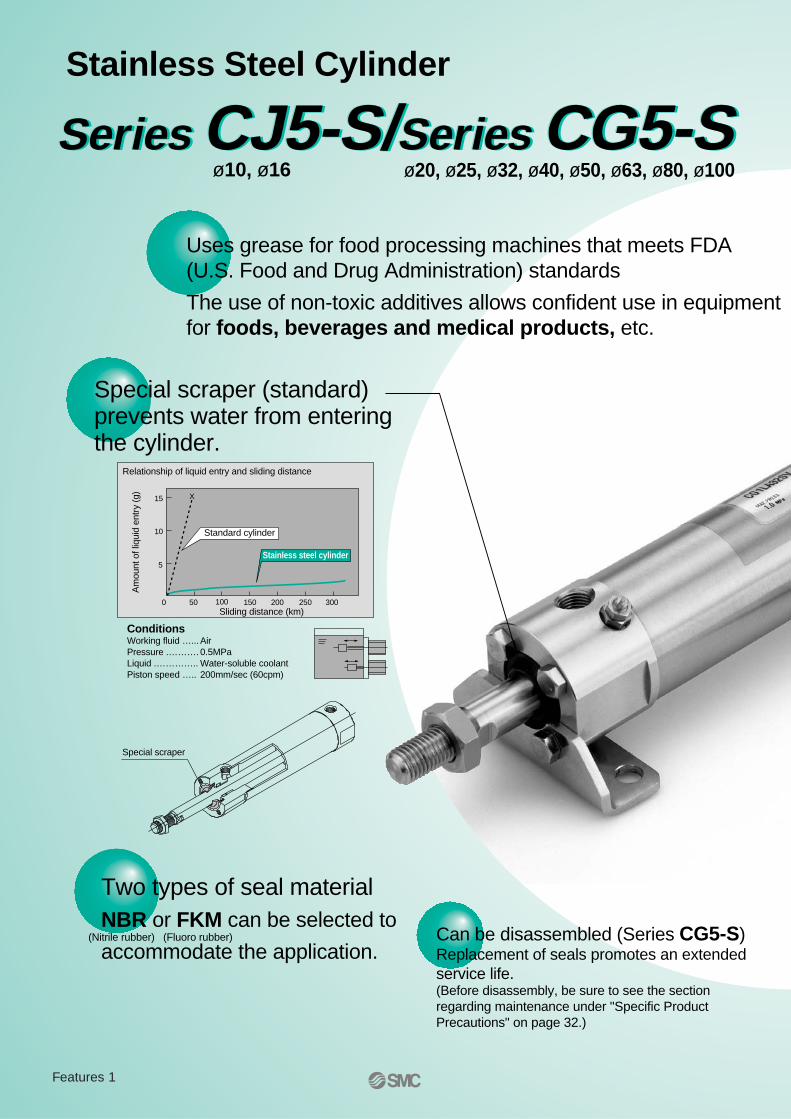
Relationship of liquid entry and sliding distance
15
10
5
0 50 100 150 200Sliding distance (km)
Standard cylinder
X
ConditionsWorking fluid …...AirPressure .………. 0.5MPaLiquid .………….. Water-soluble coolantPiston speed ….. 200mm/sec (60cpm)
Am
ount
of l
iqui
d en
try
(g)
Stainless steel cylinder
250 300
Special scraper
Uses grease for food processing machines that meets FDA (U.S. Food and Drug Administration) standards
The use of non-toxic additives allows confident use in equipment for foods, beverages and medical products, etc.
Series CJ5-S/Series CG5-SSeries CJ5-S/Series CG5-SSeries CJ5-S/Series CG5-S
Special scraper (standard) prevents water from entering the cylinder.
Two types of seal material NBR or FKM can be selected to
accommodate the application.Can be disassembled (Series CG5-S)Replacement of seals promotes an extended service life.(Before disassembly, be sure to see the section regarding maintenance under "Specific Product Precautions" on page 32.)
(Nitrile rubber) (Fluoro rubber)
Features 1
Related Equipment
Water Resistant Air Cylinders
Speed Controller with One-touch Fittings/Stainless Steel Series AS-FG
One-touch Fittings/Stainless Steel Series KG
Miniature Fittings MS
Tubing T, TU
Floating Joint/Stainless Steel Type JS
P. 18
P. 20
P. 21
P. 25
P. 26
P. 27
Series Variations
Series
CG5-S
CJ5-S
Seal materialsApplicable
auto switches10 16 20 25 32
Bore sizes (mm)
40 50 63 80 100
Water resistantD-H7BAL
Water resistantD-G5BAL
NBR
FKM
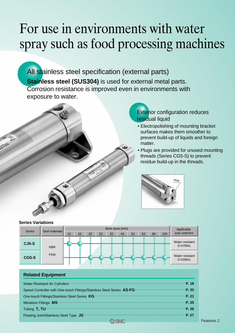
Plug
All stainless steel specification (external parts)Stainless steel (SUS304) is used for external metal parts.Corrosion resistance is improved even in environments with exposure to water.
Exterior configuration reduces residual liquid• Electropolishing of mounting bracket
surfaces makes them smoother to prevent build-up of liquids and foreign matter.
• Plugs are provided for unused mounting threads (Series CG5-S) to prevent residue build-up in the threads.
For use in environments with water spray such as food processing machines
Features 2
D-H7BAL (with indicator light)/Band mount type
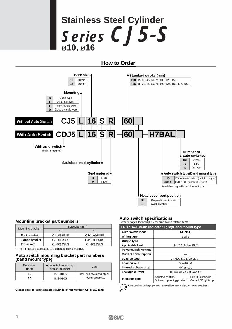
How to Order
With auto switch (built-in magnet)
With Auto Switch
BLFD
Basic typeAxial foot type
Front flange typeDouble clevis type
Mounting
ø10ø16
15, 30, 45, 60, 75, 100, 125, 15015, 30, 45, 60, 75, 100, 125, 150, 175, 200
Standard stroke (mm)
Stainless steel cylinder
CDJ5 L 16 S R 60 H7BAL
RV
NBRFKM
Seal material
NilSn
2 pcs.1 pc.
"n" pcs.
Number of auto switches
NilR
Perpendicular to axisAxial direction
Bore size (mm) Mounting bracket
Mounting bracket part numbers
Foot bracket
Flange bracket
T-bracket∗
16CJK-L016SUS
CJK-F016SUS
CJ-T016SUS
10CJ-L016SUS
CJ-F016SUS
CJ-T010SUS
Head cover port position
BH7BAL
Without auto switch (built-in magnet)
D-H7BAL (water resistant)
Available only with band mount type.
Auto switch type/Band mount type
1016
10mm16mm
Bore size
CJ5 L 16 S R 60
∗ The T-bracket is applicable to the double clevis type (D).
Auto switch specifications
Auto switch model
Wiring type
Output type
Applicable load
Power supply voltage
Current consumption
Load voltage
Load current
Internal voltage drop
Leakage current
Indicator light
D-H7BAL2 wire
—
24VDC Relay, PLC
—
—
24VDC (10 to 28VDC)
5 to 40mA
4V or less
0.8mA or less at 24VDC
Actuated position ………..…… Red LED lights upOptimum operating position … Green LED lights up
Use caution during operation as residue may collect on auto switches.
Bore size (mm)
Auto switch mounting bracket number
Note
Auto switch mounting bracket part numbers(band mount type)
Includes stainless steel mounting screws
BJ2-010S
BJ2-016S
1016
Grease pack for stainless steel cylinders/Part number: GR-R-010 (10g)
Refer to pages 15 through 17 for auto switch related items.
Without Auto Switch
1
Stainless Steel Cylinder
Se ries CJ5-Sø10, ø16
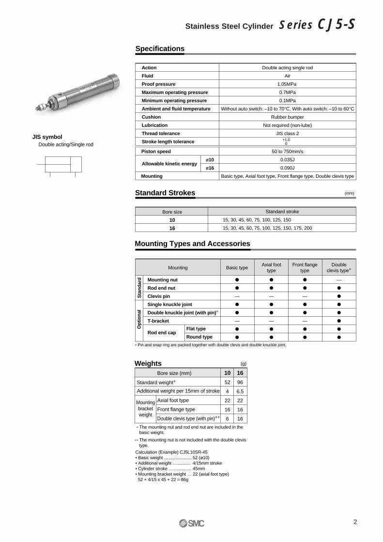
Specifications
JIS symbolDouble acting/Single rod
Action
Fluid
Proof pressure
Maximum operating pressure
Minimum operating pressure
Ambient and fluid temperature
Cushion
Lubrication
Thread tolerance
Stroke length tolerance
Double acting single rod
Air
1.05MPa
0.7MPa
0.1MPa
Without auto switch: –10 to 70°C, With auto switch: –10 to 60°C
Rubber bumper
Not required (non-lube)
JIS class 2
Mounting Types and Accessories
Mounting nut
Rod end nut
Clevis pin
Single knuckle joint
Double knuckle joint (with pin)∗
T-bracket
Mounting
Flat type
Round typeRod end cap
—
—
Basic type
—
—
Axial foottype
—
—
Front flangetype
—
Doubleclevis type∗
∗ Pin and snap ring are packed together with double clevis and double knuckle joint.
Standard Strokes
Bore size
10
16
15, 30, 45, 60, 75, 100, 125, 150
15, 30, 45, 60, 75, 100, 125, 150, 175, 200
Standard stroke
+1.00
Piston speed
Allowable kinetic energy
Mounting
50 to 750mm/s
0.035J
0.090J
Basic type, Axial foot type, Front flange type, Double clevis type
ø10
ø16
(mm)
Sta
nd
ard
Op
tion
al
(g)
Mountingbracketweight
Axial foot type
Front flange type
Double clevis type (with pin)∗∗
10
52
4
22
16
6
16
96
6.5
22
16
16
Bore size (mm)
Standard weight∗
Weights
Additional weight per 15mm of stroke
Calculation (Example) CJ5L10SR-45• Basic weight …................... 52 (ø10)• Additional weight …........... 4/15mm stroke• Cylinder stroke …............... 45mm• Mounting bracket weight … 22 (axial foot type)
52 + 4/15 x 45 + 22 = 86g
∗ The mounting nut and rod end nut are included in the basic weight.
∗∗ The mounting nut is not included with the double clevis type.
2
Stainless Steel Cylinder Series CJ5-S
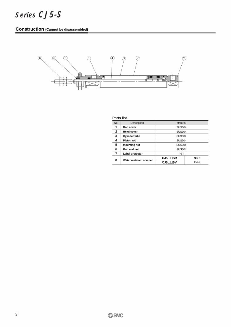
Construction (Cannot be disassembled)
No.
1234567
8
Rod cover
Head cover
Cylinder tube
Piston rod
Mounting nut
Rod end nut
Label protector
Water resistant scraper
Description
Parts listMaterial
SUS304
SUS304
SUS304
SUS304
SUS304
SUS304
PET
CJ5SRCJ5SV
NBR
FKM
3
Series CJ5-S
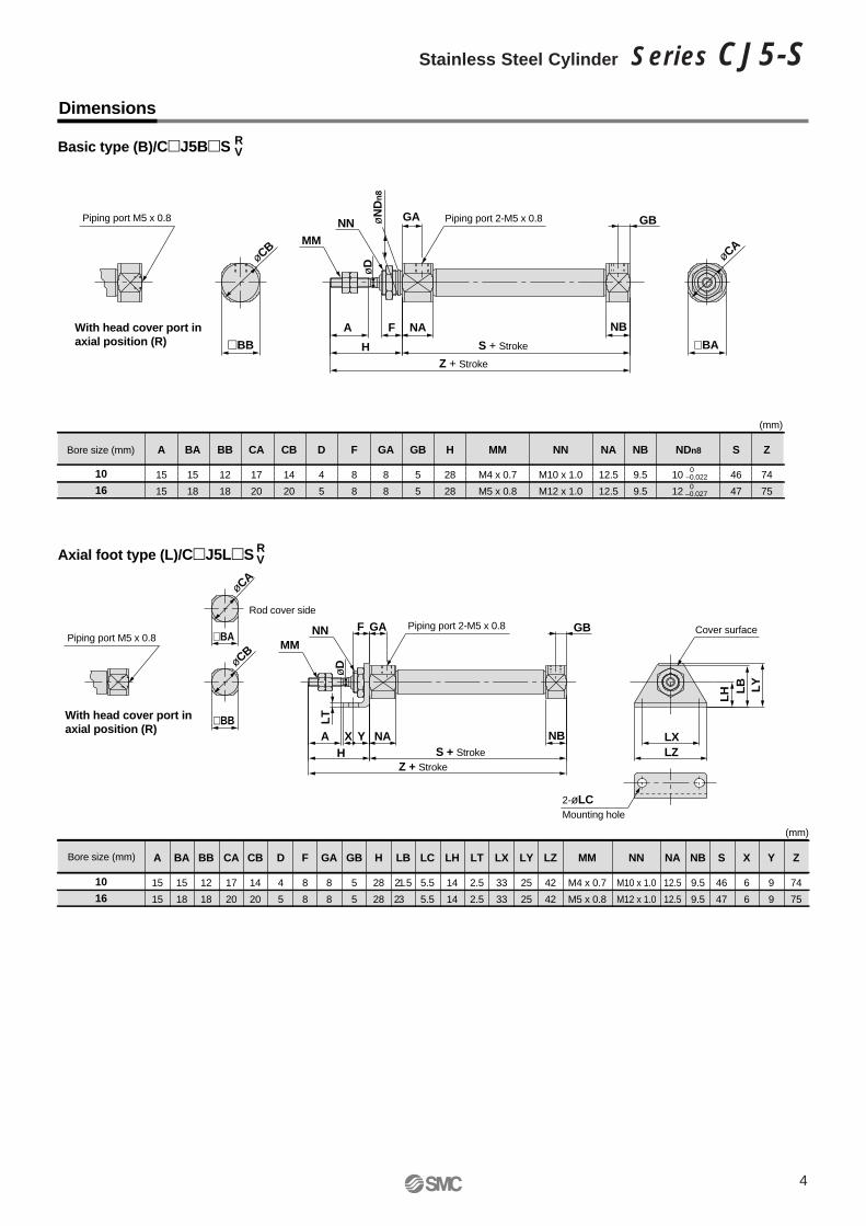
Dimensions
Bore size (mm) A
15
15
BA
15
18
BB
12
18
CA
17
20
CB
14
20
D
4
5
F
8
8
GA
8
8
GB
5
5
H
28
28
NA
12.5
12.5
NB
9.5
9.5
S
46
47
Z
74
75
MM
M4 x 0.7
M5 x 0.8
NN
M10 x 1.0
M12 x 1.0
NDn8
10
12
Basic type (B)/CJ5BS
10
16
0–0.0220
–0.027
F NA NB
S + Stroke
Z + Stroke
A
BA
MMNN
øCAøCB
øD
øD
øN
Dn
8
GA
BB H
GBPiping port 2-M5 x 0.8Piping port M5 x 0.8
With head cover port inaxial position (R)
S + StrokeZ + Stroke
øCB
øCA
Piping port 2-M5 x 0.8 Cover surfacePiping port M5 x 0.8
Rod cover side
With head cover port inaxial position (R)
Bore size (mm) A
15
15
BA
15
18
BB
12
18
CA
17
20
CB
14
20
D
4
5
F
8
8
GA
8
8
GB
5
5
H
28
28
LC
5.5
5.5
LH
14
14
LT
2.5
2.5
LX
33
33
LY
25
25
LZ
42
42
LB
21.5
23
NA
12.5
12.5
NB
9.5
9.5
S
46
47
X
6
6
Y
9
9
Z
74
75
MM
M4 x 0.7
M5 x 0.8
NN
M10 x 1.0
M12 x 1.0
Axial foot type (L)/CJ5LS
10
16
RV
RV
2-øLCMounting hole
BBNBA
GA
H
GB
X Y LXLZ
LH L
B LY
LT
BA
NA
FNNMM
(mm)
(mm)
4
Stainless Steel Cylinder Series CJ5-S
Dimensions
A
15
15
BA
15
18
BB
12
18
CA
17
20
CB
14
20
D
4
5
F
8
8
FB
17.5
19
FC
5.5
5.5
FT
2.5
2.5
FX
33
33
FY
20
20
FZ
42
42
GB
5
5
GA
8
8
H
28
28
NB
9.5
9.5
NA
12.5
12.5
S
46
47
Z
74
75
MM
M4 x 0.7
M5 x 0.8
NN
M10 x 1.0
M12 x 1.0
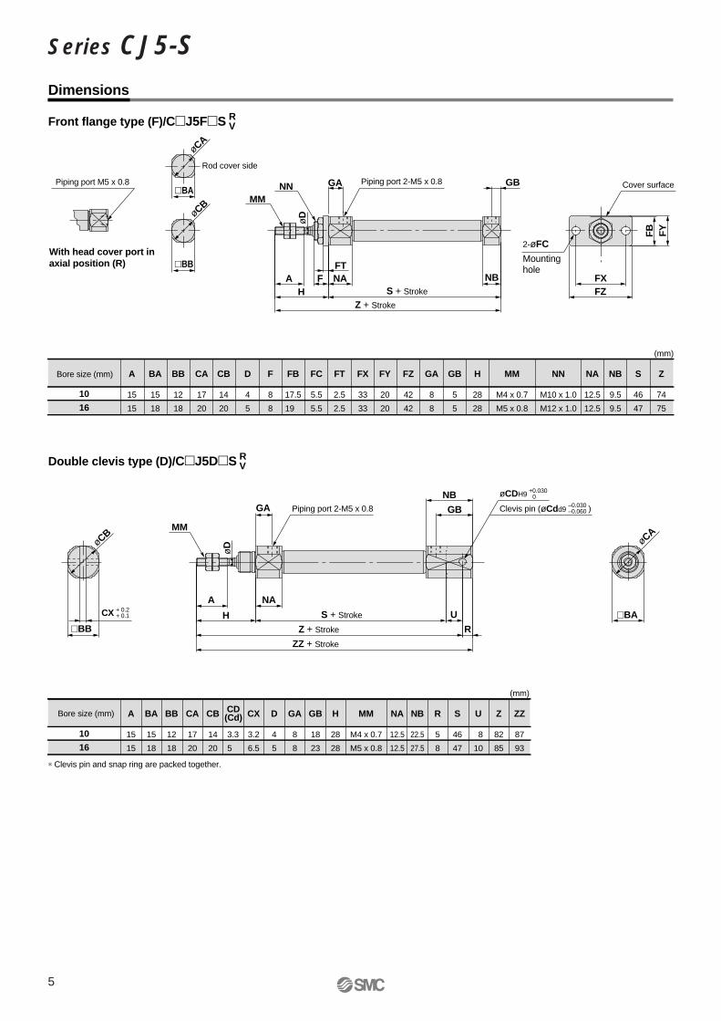
Front flange type (F)/CJ5FS
10
16
S + Stroke
Z + Strokeø
D
Piping port 2-M5 x 0.8Piping port M5 x 0.8
With head cover port inaxial position (R)
A
15
15
BA
15
18
BB
12
18
CA
17
20
3.3
5
CX
3.2
6.5
D
4
5
GA
8
8
GB
18
23
H
28
28
CB
14
20
NA
12.5
12.5
NB
22.5
27.5
S
46
47
R
5
8
U
8
10
Z
82
85
ZZ
87
93
MM
M4 x 0.7
M5 x 0.8
Double clevis type (D)/CJ5DS
10
16
RV
RV
∗ Clevis pin and snap ring are packed together.
2-øFC
Mountinghole
NBA
GANNMM
H
GB
FXFZ
NAFFT
FY
FB
Cover surface
øCB
øCA
Rod cover side
BB
BA
NAA
GA
BBH
GB
NB
R
U BA
øCA
S + Stroke
Z + Stroke
ZZ + Stroke
MM
øD
Piping port 2-M5 x 0.8 Clevis pin ( )
øCDH9 +0.0300
øCdd9–0.030–0.060
CX + 0.2 + 0.1
øCB
Bore size (mm)
Bore size (mm)
CD (Cd)
(mm)
(mm)
5
Series CJ5-S
Part no.Applicablebore size
(mm)L1
21
25
3.3
5
A1
8
8
NDH10MM
M4 x 0.7
M5 x 0.8
U1
9
14
R1
8
12
NX
3.1
6.4
I-J010SUS
I-J016SUS
10
16
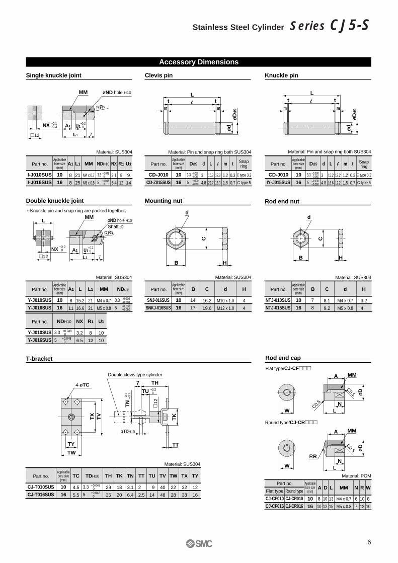
Accessory Dimensions
Single knuckle joint
+0.0480
+0.0480
MM
–0.1–0.3NX
7
+0.20A1 U1
+0.20U1
L₁
øND hole H10
7
A1
L1
MMøND hole H10
Shaft d9
øTDH10
4-øTC
12
L
Part no.Applicablebore size
(mm)
Snapring
C type 3.2
C type 5
3.3
5
Dd9 t
0.3
0.7
m
1.2
1.5
L
15.2
22.7
d
3
4.8
l
12.2
18.3
CD-J010
CD-Z015SUS
10
16
Clevis pin
–0.030–0.060–0.030–0.060
Material: SUS304 Material: Pin and snap ring both SUS304
l ttm m
ød
øD
d9
ød
øD
d9
L
Part no.Applicablebore size
(mm)Snapring
C type 3.2
C type 5
3.3
5
Dd9 t
0.3
0.7
m
1.2
1.5
L
15.2
16.6
d
3
4.8
l
12.2
12.2
CD-J010
IY-J015SUS
10
16
Knuckle pin
–0.030–0.060–0.030–0.060
Material: Pin and snap ring both SUS304
l tt
m m
L
Part no.Applicablebore size
(mm)L1
21
21
3.3
5
A1
8
11
NDd9MM
M4 x 0.7
M5 x 0.8
L
15.2
16.6
Y-J010SUS
Y-J016SUS
10
16
Double knuckle joint
–0.030–0.060–0.030–0.060
Part no.
3.3
5
NDH10 U1
10
10
R1
8
12
NX
3.2
6.5
Y-J010SUS
Y-J016SUS
+0.0480
+0.20
+0.0480
Part no.Applicablebore size
(mm)
14
17
B C
16.2
19.6
H
4
4
SNJ-016SUS
SNKJ-016SUS
10
16
Mounting nut
Material: SUS304 Material: SUS304
Part no.Applicablebore size
(mm)
NTJ-010SUS
NTJ-015SUS
10
16
Rod end nut
Material: SUS304
∗ Knuckle pin and snap ring are packed together.
Part no.Applicablebore size
(mm) TH
29
35
TK
18
20
TN
3.1
6.4
TT
2
2.5
TU
9
14
TV
40
48
TW
22
28
TX
32
38
TY
12
16
3.3
5
TC
4.5
5.5
TDH10
CJ-T010SUS
CJ-T016SUS
10
16
T-bracket
+0.0480
+0.0480
Material: SUS304
d
M10 x 1.0
M12 x 1.0
7
8
C
8.1
9.2
H
3.2
4
d
M4 x 0.7
M5 x 0.8
B
+0.20NX
12B H
d
C
d
B H
C
Part no. Applicablebore size
(mm) Flat type
CJ-CF010
CJ-CF016
Flat type/CJ-CF
Round type
CJ-CR010
CJ-CR016
Round type/CJ-CR
10
16
Rod end cap
Material: POM
10
12
L
13
15
W
8
10
R
10
12
N
6
7
MM
M4 x 0.7
M5 x 0.8
D
8
10
A
MM
MM
RR
TK
12
TT
TX
TV
TH
TU
–0.1
–0.3
TN
7
TY
TW
Double clevis type cylinder
RR1
RR1
A
A
L
øD
øD
W
W
N
LN
C0.5
C0.5
C0.5
6
Stainless Steel Cylinder Series CJ5-S
D-G5BAL (With indicator light)/Band mount type
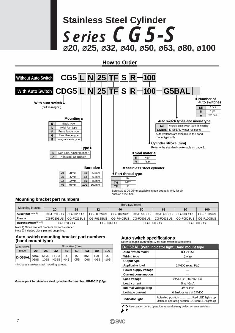
How to Order
With auto switch (built-in magnet)
With Auto Switch
BLFGE
Basic typeAxial foot type
Front flange typeRear flange type
Integral clevis type
Mounting
Cylinder stroke (mm)Refer to the standard stroke table on page 8.
Stainless steel cylinder
CDG5 L N 25 S 100 G5BAL
RV
NBRFKM
Seal material
NilSn
2 pcs.1 pc.
"n" pcs.
Number of auto switches
Bore size (mm) Mounting bracket
Mounting bracket part numbers
Axial foot Note 1)
Flange
Trunnion bracket Note 2)
25CG-L025SUS
CG-F025SUS
32CG-L032SUS
CG-F032SUS
40CG-L040SUS
CG-F040SUS
50CG-L050SUS
CG-F050SUS
63CG-L063SUS
CG-F063SUS
80CG-L080SUS
CG-F080SUS
100CG-L100SUS
CG-F100SUS
20CG-L020SUS
CG-F020SUS
CG-E020SUS
NBA-088S
NBA-106S
BGS1-032S
BAF-04S
BAF-05S
BAF-06S
BAF-08S
BAF-10S
CG-E032SUS CG-E050SUS CG-E080SUS
NilG5BAL
Without auto switch (built-in magnet)D-G5BAL (water resistant)
Auto switch type/Band mount type
506380
100
50mm63mm80mm
100mm
20253240
20mm25mm32mm40mm
Bore size
NA
Non-lube, rubber bumperNon-lube, air cushion
Type
CG5 L N 25 S
R
R 100
Note 1) Order two foot brackets for each cylinder.Note 2) Includes clevis pin and snap ring.
Auto switch specifications
Auto switch model
Wiring type
Output type
Applicable load
Power supply voltage
Current consumption
Load voltage
Load current
Internal voltage drop
Leakage current
Indicator light
D-G5BAL2 wire
—
24VDC relay, PLC
—
—
24VDC (10 to 28VDC)
5 to 40mA
4V or less
0.8mA or less at 24VDC
Actuated position ……....… Red LED lights upOptimum operating position …Green LED lights up
Auto switchmodel
Bore size (mm)
Auto switch mounting bracket part numbers (band mount type)
D-G5BAL
20 25 32 40 50 63 80 100
∗ Includes stainless steel mounting screws.
Refer to pages 15 through 17 for auto switch related items.
Grease pack for stainless steel cylinders/Part number: GR-R-010 (10g)
Use caution during operation as residue may collect on auto switches.
Without Auto Switch
Auto switches are available in the band mount type only.
TF
TF
-TNTF
RcNPT
G
Port thread type
Bore size-Ø 20-25mm available in port thread M only for air cushion execution.
7
Stainless Steel Cylinder
Se ries CG5-Sø20, ø25, ø32, ø40, ø50, ø63, ø80, ø100
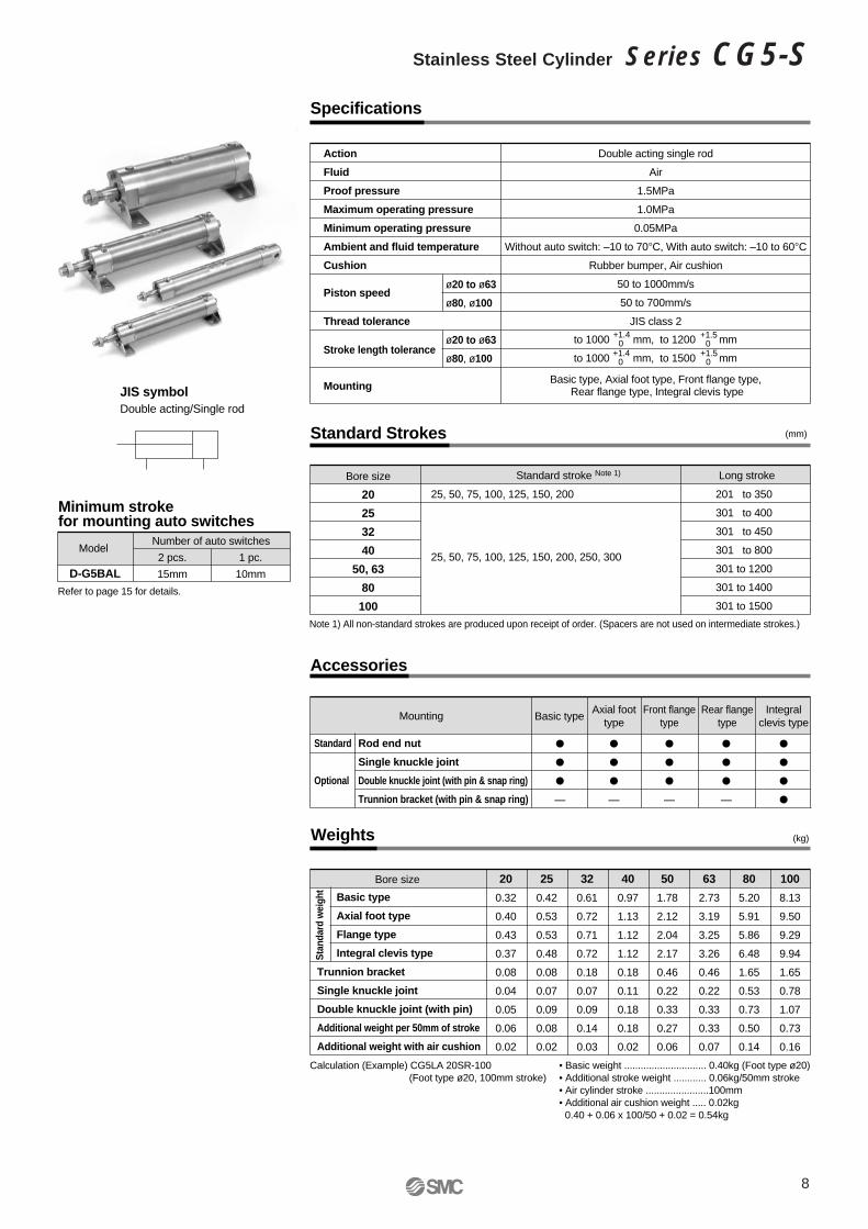
Specifications
Action
Fluid
Proof pressure
Maximum operating pressure
Minimum operating pressure
Ambient and fluid temperature
Cushion
Thread tolerance
Double acting single rod
Air
1.5MPa
1.0MPa
0.05MPa
Without auto switch: –10 to 70°C, With auto switch: –10 to 60°C
Rubber bumper, Air cushion
50 to 1000mm/s
50 to 700mm/s
JIS class 2
Accessories
Rod end nut
Single knuckle joint
Double knuckle joint (with pin & snap ring)
Trunnion bracket (with pin & snap ring)
Mounting Basic typeAxial foot
type
—
Rear flangetype
—
—
—
Front flangetype
Integralclevis type
Standard Strokes
Bore size
20
25
32
40
50, 63
80
100
25, 50, 75, 100, 125, 150, 200
Note 1) All non-standard strokes are produced upon receipt of order. (Spacers are not used on intermediate strokes.)
25, 50, 75, 100, 125, 150, 200, 250, 300
201 to 350
301 to 400
301 to 450
301 to 800
301 to 1200
301 to 1400
301 to 1500
Standard stroke Long stroke
+1.40
+1.50
+1.40
+1.50
Piston speed
Stroke length tolerance
Mounting
to 1000 mm, to 1200 mm
to 1000 mm, to 1500 mm
ø20 to ø63
ø80, ø100
ø20 to ø63
ø80, ø100
(mm)
(kg)
Basic type, Axial foot type, Front flange type, Rear flange type, Integral clevis type
Standard
Optional
Weights
Basic type
Axial foot type
Flange type
Integral clevis type
Trunnion bracket
Single knuckle joint
Double knuckle joint (with pin)
Additional weight per 50mm of stroke
Additional weight with air cushion
Bore size 100
8.13
9.50
9.29
9.94
1.65
0.78
1.07
0.73
0.16
80
5.20
5.91
5.86
6.48
1.65
0.53
0.73
0.50
0.14
63
2.73
3.19
3.25
3.26
0.46
0.22
0.33
0.33
0.07
50
1.78
2.12
2.04
2.17
0.46
0.22
0.33
0.27
0.06
40
0.97
1.13
1.12
1.12
0.18
0.11
0.18
0.18
0.02
32
0.61
0.72
0.71
0.72
0.18
0.07
0.09
0.14
0.03
25
0.42
0.53
0.53
0.48
0.08
0.07
0.09
0.08
0.02
20
0.32
0.40
0.43
0.37
0.08
0.04
0.05
0.06
0.02
Number of auto switchesModel
Minimum stroke for mounting auto switches
D-G5BAL2 pcs.
15mm
1 pc.
10mm
Refer to page 15 for details.
Stan
dard
wei
ght
Calculation (Example) CG5LA 20SR-100(Foot type ø20, 100mm stroke)
• Basic weight .............................. 0.40kg (Foot type ø20) • Additional stroke weight ............ 0.06kg/50mm stroke• Air cylinder stroke .......................100mm• Additional air cushion weight ..... 0.02kg
0.40 + 0.06 x 100/50 + 0.02 = 0.54kg
JIS symbolDouble acting/Single rod
Note 1)
8
Stainless Steel Cylinder Series CG5-S
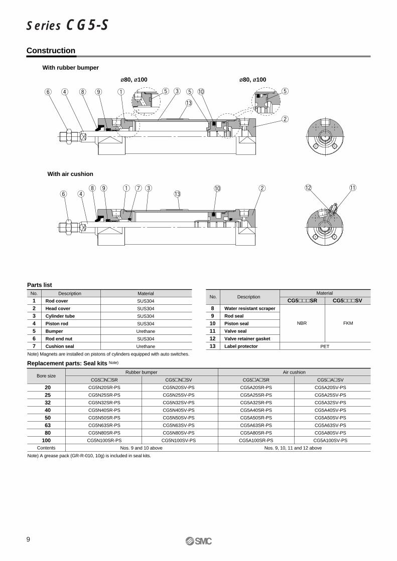
Construction
With rubber bumper
ø80, ø100 ø80, ø100
With air cushion
Bore size
Contents
20253240506380
100
Replacement parts: Seal kits Note)
CG5NSR
CG5N20SR-PS
CG5N25SR-PS
CG5N32SR-PS
CG5N40SR-PS
CG5N50SR-PS
CG5N63SR-PS
CG5N80SR-PS
CG5N100SR-PS
CG5NSV
CG5N20SV-PS
CG5N25SV-PS
CG5N32SV-PS
CG5N40SV-PS
CG5N50SV-PS
CG5N63SV-PS
CG5N80SV-PS
CG5N100SV-PS
Rubber bumper Air cushion
Nos. 9 and 10 above
CG5ASR
CG5A20SR-PS
CG5A25SR-PS
CG5A32SR-PS
CG5A40SR-PS
CG5A50SR-PS
CG5A63SR-PS
CG5A80SR-PS
CG5A100SR-PS
CG5ASV
CG5A20SV-PS
CG5A25SV-PS
CG5A32SV-PS
CG5A40SV-PS
CG5A50SV-PS
CG5A63SV-PS
CG5A80SV-PS
CG5A100SV-PS
Nos. 9, 10, 11 and 12 above
Note) A grease pack (GR-R-010, 10g) is included in seal kits.
No.
1234567
Rod cover
Head cover
Cylinder tube
Piston rod
Bumper
Rod end nut
Cushion seal
Description
Parts listMaterial
SUS304
SUS304
SUS304
SUS304
Urethane
SUS304
Urethane
No.
8910111213
Water resistant scraper
Rod seal
Piston seal
Valve seal
Valve retainer gasket
Label protector
DescriptionMaterial
NBR
PET
CG5SR
FKM
CG5SV
Note) Magnets are installed on pistons of cylinders equipped with auto switches.
9
Series CG5-S
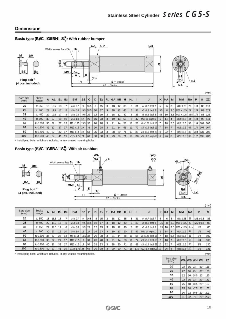
Dimensions
Bore size(mm)
Strokerange A
18
22
22
30
35
35
40
40
to 350
to 400
to 450
to 800
to 1200
to 1200
to 1400
to 1500
B1
13
17
17
19
27
27
32
41
B2
7
8
8
10
13
17
17
19
AL
15.5
19.5
19.5
27
32
32
37
37
C
16.5
18.5
20
26
32
38
50
60
BZ
9
9.5
9.5
12
15.5
19
19
24
D
8
10
12
16
20
20
25
30
H1
5
6
6
8
11
11
13
16
F1
3
3
3
3
3
3
3
3
E1
15
17
19
23
28
28
33
38
H
35
40
40
50
58
58
71
71
GB
12
12
12
13
14
14
20
20
GA
18
18
18
19
21
21
28
29
I
31
33
38
47
58
72
89
110
M
3
3.5
3.5
4
5.5
7
7
8
KA
6
8
10
14
18
18
22
26
K
5
5.5
5.5
6
7
7
10
10
NA
29
29
35.5
44
55
69
80
100
P
1/8
1/8
1/8
1/8
1/4
1/4
3/8
1/2
S
83
83
85
93
109
109
130
131
ZZ
118
123
125
143
167
167
201
202
MM
M8 x 1.25
M10 x 1.25
M10 x 1.25
M14 x 1.5
M18 x 1.5
M18 x 1.5
M22 x 1.5
M26 x 1.5
BM
M4 x 0.7
M5 x 0.8
M5 x 0.8
M6 x 1.0
M8 x 1.25
M10 x 1.5
M10 x 1.5
M12 x 1.75
J
M4 x 0.7 depth 7
M5 x 0.8 depth 8
M5 x 0.8 depth 8
M6 x 1.0 depth 12
M8 x 1.25 depth 16
M10 x 1.5 depth 16
M10 x 1.5 depth 22
M12 x 1.75 depth 23
Basic type (B)/CG5BNS : With rubber bumper
20
25
32
40
50
63
80
100
20
25
32
40
50
63
80
100
RV
Strokerange A
18
22
22
30
35
35
40
40
to 350
to 400
to 450
to 800
to 1200
to 1200
to 1400
to 1500
B1
13
17
17
19
27
27
32
41
B2
7
8
8
10
13
17
17
19
AL
15.5
19.5
19.5
27
32
32
37
37
C
16.5
18.5
20
26
32
38
50
60
BZ
9
9.5
9.5
12
15.5
19
19
24
D
8
10
12
16
20
20
25
30
H1
5
6
6
8
11
11
13
16
F1
3
3
3
3
3
3
3
3
E1
15
17
19
23
28
28
33
38
H
35
40
40
50
58
58
71
71
GB
12
12
12
13
14
14
20
20
GA
18
18
18
19
21
21
28
29
I
31
33
38
47
58
72
89
110
M
3
3.5
3.5
4
5.5
7
7
8
KA
6
8
10
14
18
18
22
26
K
5
5.5
5.5
6
7
7
10
10
NA
29
29
35.5
44
55
69
80
100
P
M5 x 0.8
M5 x 0.8
1/8
1/8
1/4
1/4
3/8
1/2
S
83
83
85
93
109
109
130
131
WA
22
22
22
22
25
25
30
31
WB
16
16
16
16
18
18
22
22
WH
23
25
28.5
33
40.5
47.5
60.5
71
Wθ
30° 30° 25° 20° 20° 20° 20° 20°
ZZ
118
123
125
143
167
167
201
202
MM
M8 x 1.25
M10 x 1.25
M10 x 1.25
M14 x 1.5
M18 x 1.5
M18 x 1.5
M22 x 1.5
M26 x 1.5
BM
M4 x 0.7
M5 x 0.8
M5 x 0.8
M6 x 1.0
M8 x 1.25
M10 x 1.5
M10 x 1.5
M12 x 1.75
J
M4 x 0.7 depth 7
M5 x 0.8 depth 8
M5 x 0.8 depth 8
M6 x 1.0 depth 12
M8 x 1.25 depth 16
M10 x 1.5 depth 16
M10 x 1.5 depth 22
M12 x 1.75 depth 23
Basic type (B)/CG5BAS : With air cushion
20
25
32
40
50
63
80
100
R V
ALA
H
H1
(F1)
Width across flats B1
(øE
1)
2- P
K
C
NA
KA
8-J
GA GB
MMBZ B2
M BM
ALA
H
2-P
K
NA
KA8-J
GA GB
MM
Max
. WH
WA WB
BZ
M BM
∗ Install plug bolts, which are included, in any unused mounting holes.
∗ Install plug bolts, which are included, in any unused mounting holes.
S + StrokeZZ + Stroke
(F1)
B2
S + StrokeZZ + Stroke
øI
øI
øD
H1Width across flats B1
(øE
1)
øD
Plug bolt ∗ (4 pcs. included)
Plug bolt ∗ (4 pcs. included)
Wθ°10°
±0.1
C ±0.1
Bore size (mm)
(mm)
(mm)
(mm)
Bore size (mm)
10
Stainless Steel Cylinder Series CG5-S
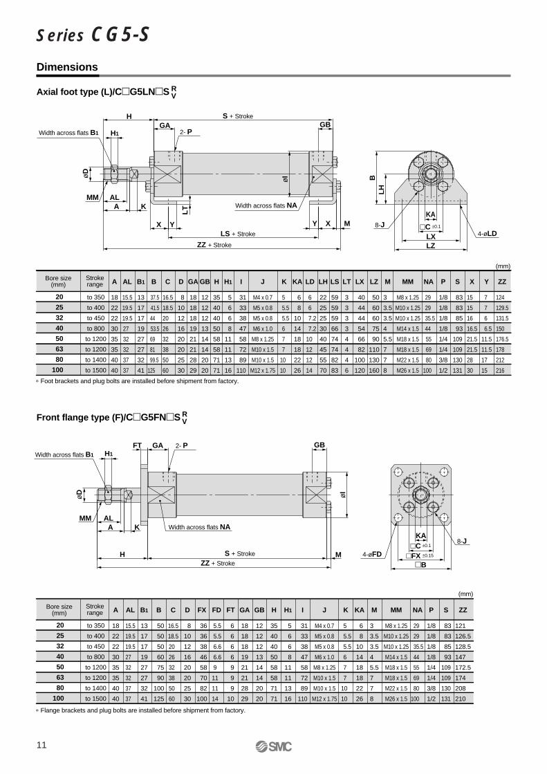
Dimensions
Bore size (mm)
Strokerange A
18
22
22
30
35
35
40
40
to 350
to 400
to 450
to 800
to 1200
to 1200
to 1400
to 1500
B1
13
17
17
19
27
27
32
41
B
37.5
41.5
44
53.5
69
81
99.5
125
AL
15.5
19.5
19.5
27
32
32
37
37
C
16.5
18.5
20
26
32
38
50
60
D
8
10
12
16
20
20
25
30
H1
5
6
6
8
11
11
13
16
H
35
40
40
50
58
58
71
71
GB
12
12
12
13
14
14
20
20
GA
18
18
18
19
21
21
28
29
I
31
33
38
47
58
72
89
110
M
3
3.5
3.5
4
5.5
7
7
8
KA
6
8
10
14
18
18
22
26
LD
6
6
7.2
7.2
10
12
12
14
LH
22
25
25
30
40
45
55
70
LS
59
59
59
66
74
74
82
83
LT
3
3
3
3
4
4
4
6
LX
40
44
44
54
66
82
100
120
LZ
50
60
60
75
90
110
130
160
K
5
5.5
5.5
6
7
7
10
10
NA
29
29
35.5
44
55
69
80
100
P
1/8
1/8
1/8
1/8
1/4
1/4
3/8
1/2
S
83
83
85
93
109
109
130
131
X
15
15
16
16.5
21.5
21.5
28
30
Y
7
7
6
6.5
11.5
11.5
17
15
ZZ
124
129.5
131.5
150
176.5
178
212
216
MM
M8 x 1.25
M10 x 1.25
M10 x 1.25
M14 x 1.5
M18 x 1.5
M18 x 1.5
M22 x 1.5
M26 x 1.5
J
M4 x 0.7
M5 x 0.8
M5 x 0.8
M6 x 1.0
M8 x 1.25
M10 x 1.5
M10 x 1.5
M12 x 1.75
Axial foot type (L)/CG5LNS
20
25
32
40
50
63
80
100
RV
Strokerange A
18
22
22
30
35
35
40
40
to 350
to 400
to 450
to 800
to 1200
to 1200
to 1400
to 1500
B1
13
17
17
19
27
27
32
41
B
50
50
50
60
75
90
100
125
AL
15.5
19.5
19.5
27
32
32
37
37
C
16.5
18.5
20
26
32
38
50
60
FX
36
36
38
46
58
70
82
100
FD
5.5
5.5
6.6
6.6
9
11
11
14
FT
6
6
6
6
9
9
9
10
D
8
10
12
16
20
20
25
30
H1
5
6
6
8
11
11
13
16
H
35
40
40
50
58
58
71
71
GB
12
12
12
13
14
14
20
20
GA
18
18
18
19
21
21
28
29
I
31
33
38
47
58
72
89
110
M
3
3.5
3.5
4
5.5
7
7
8
KA
6
8
10
14
18
18
22
26
K
5
5.5
5.5
6
7
7
10
10
NA
29
29
35.5
44
55
69
80
100
P
1/8
1/8
1/8
1/8
1/4
1/4
3/8
1/2
S
83
83
85
93
109
109
130
131
ZZ
121
126.5
128.5
147
172.5
174
208
210
MM
M8 x 1.25
M10 x 1.25
M10 x 1.25
M14 x 1.5
M18 x 1.5
M18 x 1.5
M22 x 1.5
M26 x 1.5
J
M4 x 0.7
M5 x 0.8
M5 x 0.8
M6 x 1.0
M8 x 1.25
M10 x 1.5
M10 x 1.5
M12 x 1.75
Front flange type (F)/CG5FNS
20
25
32
40
50
63
80
100
RV
∗ Flange brackets and plug bolts are installed before shipment from factory.
∗ Foot brackets and plug bolts are installed before shipment from factory.
ALA K
KA8-J
4-øLDC
GA GB
MM
LXLZ
BL
H
X Y XY
H
H1
M
LT Width across flats NA
ALA
H
KKA
GA GB
MM
B
FT
M
Width across flats NA
±0.1
8-J
4-øFDC ±0.1
FX ±0.15
Width across flats B1 2- P
LS + Stroke
S + Stroke
ZZ + Stroke
2- P
S + Stroke
ZZ + Stroke
øD
H1Width across flats B1
øD
øI
øI
(mm)
Bore size (mm)
(mm)
11
Series CG5-S
Dimensions
Strokerange A
18
22
22
30
35
35
40
40
to 200
to 300
to 300
to 500
to 600
to 600
to 750
to 750
B1
13
17
17
19
27
27
32
41
B
50
50
50
60
75
90
100
125
AL
15.5
19.5
19.5
27
32
32
37
37
C
16.5
18.5
20
26
32
38
50
60
FX
36
36
38
46
58
70
82
100
FT
6
6
6
6
9
9
9
10
FD
5.5
5.5
6.6
6.6
9
11
11
14
D
8
10
12
16
20
20
25
30
H1
5
6
6
8
11
11
13
16
H
35
40
40
50
58
58
71
71
GB
12
12
12
13
14
14
20
20
GA
18
18
18
19
21
21
28
29
I
31
33
38
47
58
72
89
110
M
3
3.5
3.5
4
5.5
7
7
8
KA
6
8
10
14
18
18
22
26
K
5
5.5
5.5
6
7
7
10
10
NA
29
29
35.5
44
55
69
80
100
P
1/8
1/8
1/8
1/8
1/4
1/4
3/8
1/2
S
83
83
85
93
109
109
130
131
ZZ
124
129
131
149
176
176
210
212
MM
M8 x 1.25
M10 x 1.25
M10 x 1.25
M14 x 1.5
M18 x 1.5
M18 x 1.5
M22 x 1.5
M26 x 1.5
J
M4 x 0.7
M5 x 0.8
M5 x 0.8
M6 x 1.0
M8 x 1.25
M10 x 1.5
M10 x 1.5
M12 x 1.75
Rear flange type (G)/CG5GNS
20
25
32
40
50
63
80
100
RV
Strokerange
A
18
22
22
30
35
35
40
40
to 200
to 300
to 300
to 500
to 600
to 600
to 750
to 750
Trunnionbracket
CG-E020SUS
CG-E020SUS
CG-E032SUS
CG-E032SUS
CG-E050SUS
CG-E050SUS
CG-E080SUS
CG-E080SUS
B1
13
17
17
19
27
27
32
41
AL
15.5
19.5
19.5
27
32
32
37
37
C
16.5
18.5
20
26
32
38
50
60
CD(hole)
øCD hole H10Shaft d9
8
8
10
10
14
14
22
22
CI
25
27
32
40
50
60
75
90
D
8
10
12
16
20
20
25
30
H1
5
6
6
8
11
11
13
16
CX
16
16
24
24
40
40
60
60
H
35
40
40
50
58
58
71
71
GB
12
12
12
13
14
14
20
20
GA
18
18
18
19
21
21
28
29
I
31
33
38
47
58
72
89
110
M
3
3.5
3.5
4
5.5
7
7
8
L
14
14
16
16
22
22
33
33
KA
6
8
10
14
18
18
22
26
K
5
5.5
5.5
6
7
7
10
10
NA
29
29
35.5
44
55
69
80
100
P
1/8
1/8
1/8
1/8
1/4
1/4
3/8
1/2
RR
9
9
11
11
15
15
23
23
S
83
83
85
93
109
109
130
131
U
13
13
15
15
21
21
32
32
LD
7
7
7
7
12
12
14
14
LE
9
9
11
11
15
15
23
23
LF
2
2
4
4
5
5
6
6
LG
14
14
22
22
25
25
40
40
LP
21
21
29
29
35
35
57
57
LT
3
3
4
4
6
6
9
9
LX
42
42
56
56
84
84
120
120
LY
30
30
40
40
50
50
80
80
LZ
153
158
170
188
224
224
291
292
LV
56.5
56.5
70.5
70.5
106.5
106.5
144.5
144.5
LH
30
30
40
40
50
50
80
80
LL
27.6
27.6
38.4
38.4
59.6
59.6
87.2
87.2
Z
132
137
141
159
189
189
234
235
ZZ
141
146
152
170
204
204
257
258
MM
M8 x 1.25
M10 x 1.25
M10 x 1.25
M14 x 1.5
M18 x 1.5
M18 x 1.5
M22 x 1.5
M26 x 1.5
J
M4 x 0.7
M5 x 0.8
M5 x 0.8
M6 x 1.0
M8 x 1.25
M10 x 1.5
M10 x 1.5
M12 x 1.75
Integral clevis type (E)/CG5ENS
20
25
32
40
50
63
80
100
20
25
32
40
50
63
80
100
RV
∗ Plug bolts are installed before shipment from factory.∗ Trunnion brackets (with clevis pin and snap ring) are optional. (Not included.)
∗ Flange brackets and plug bolts are installed before shipment from factory.
+0.0580
CD(shaft)
8
8
10
10
14
14
22
22
–0.040–0.076–0.040–0.076–0.040–0.076–0.040–0.076–0.050–0.093–0.050–0.093–0.065–0.117–0.065–0.117
0–0.2
0–0.2
0–0.2
0–0.2
0–0.2
0–0.2
0–0.3
0–0.3
+0.0580
+0.0580
+0.0580
+0.0700
+0.0700
+0.0840
+0.0840
ALA K
NA
KA4-J
GA GB
MM
H
L
LF
LY
LT
RRU
LVLX
CXLL
LH LE
M
LPLG
ALA
H
K
GA GB
MM
FT
M
Width across flats KA
Width across flats NA
H1Width across flats B1
øD
2- P
øI
S + Stroke
ZZ + Stroke
8-J4-øFD
4-øLD
C ±0.1
C ±0.1
FX ±0.15
B
øC
I
øI
ZZ + Stroke
2- PH1Width across flats B1
øD
S + StrokeZ + Stroke
LZ + Stroke
Bore size (mm)
Bore size (mm)
(mm)
(mm)
(mm)
Bore size (mm)
12
Stainless Steel Cylinder Series CG5-S
Part no.Applicablebore size
(mm)E1
16
20
22
28
38
45
8
10
18
22
28
32
A1
8.5
10.5
14
18
21
21
A
34
41
42
56
71
79
NXMM
M8 x 1.25
M10 x 1.25
M14 x 1.5
M18 x 1.5
M22 x 1.5
M26 x 1.5
U1
11.5
14
14
20
27
31
R1
10.3
12.8
12
16
21
24
L1
25
30
30
40
50
55
I-G02SUS
I-G03SUS
I-G04SUS
I-G05SUS
I-G08SUS
I-G10SUS
20
25, 32
40
50, 63
80
100
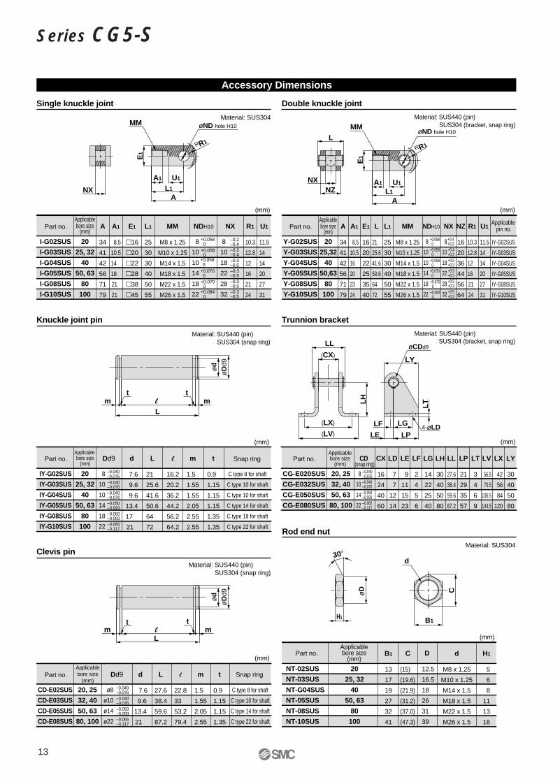
Accessory Dimensions
Single knuckle joint
–0.2–0.48
10
10
14
18
22
NDH10
+0.058 0 +0.058 0 +0.058 0 +0.070 0 +0.070 0 +0.084 0
–0.2–0.4–0.3–0.5–0.3–0.5–0.3–0.5–0.3–0.5
øND hole H10
ød
øD
d9
(mm)
Material: SUS304
Part no.Applicablebore size
(mm)E1
16
20
22
25
35
40
8
10
18
22
28
32
A1
8.5
10.5
16
20
23
24
A
34
41
42
56
71
79
Applicable pin no.
IY-G02SUS
IY-G03SUS
IY-G04SUS
IY-G05SUS
IY-G08SUS
IY-G10SUS
NXMM
M8 x 1.25
M10 x 1.25
M14 x 1.5
M18 x 1.5
M22 x 1.5
M26 x 1.5
U1
11.5
14
14
20
27
31
NZ
16
20
36
44
56
64
L
21
25.6
41.6
50.6
64
72
R1
10.3
12.8
12
16
21
24
L1
25
30
30
40
50
55
Y-G02SUS
Y-G03SUS
Y-G04SUS
Y-G05SUS
Y-G08SUS
Y-G10SUS
20
25,32
40
50,63
80
100
Double knuckle joint
+0.4+0.2+0.4+0.2+0.5+0.3+0.5+0.3+0.5+0.3+0.5+0.3
8
10
10
14
18
22
NDH10
+0.058 0 +0.058 0 +0.058 0 +0.070 0 +0.070 0 +0.084 0
(mm)
Material: SUS440 (pin)SUS304 (bracket, snap ring)
Material: SUS440 (pin)SUS304 (snap ring)
Part no.Applicable bore size
(mm)
8
10
10
14
18
22
Dd9 t
0.9
1.15
1.15
1.15
1.35
1.35
m
1.5
1.55
1.55
2.05
2.55
2.55
d
7.6
9.6
9.6
13.4
17
21
L
21
25.6
41.6
50.6
64
72
l
16.2
20.2
36.2
44.2
56.2
64.2
IY-G02SUS
IY-G03SUS
IY-G04SUS
IY-G05SUS
IY-G08SUS
IY-G10SUS
20
25, 32
40
50, 63
80
100
Knuckle joint pin
–0.040–0.076–0.040–0.076–0.050–0.093–0.050–0.093–0.065–0.117
–0.040–0.076
(mm)
Part no.Applicablebore size
(mm)Snap ring
C type 8 for shaft
C type 10 for shaft
C type 10 for shaft
C type 14 for shaft
C type 18 for shaft
C type 22 for shaft
Material: SUS440 (pin)SUS304 (snap ring)
Part no.Applicablebore size
(mm)
ø8
ø10
ø14
ø22
Dd9 t
0.9
1.15
1.15
1.35
m
1.5
1.55
2.05
2.55
d
7.6
9.6
13.4
21
L
27.6
38.4
59.6
87.2
l
22.8
33
53.2
79.4
CD-E02SUS
CD-E03SUS
CD-E05SUS
CD-E08SUS
20, 25
32, 40
50, 63
80, 100
Clevis pin
–0.040–0.076–0.050–0.093–0.065–0.117
–0.040–0.076
(mm)
Snap ring
C type 8 for shaft
C type 10 for shaft
C type 14 for shaft
C type 22 for shaft
Material: SUS304
Part no.Applicablebore size
(mm)D
12.5
16.5
18
26
31
39
C
(15)
(19.6)
(21.9)
(31.2)
(37.0)
(47.3)
B1
13
17
19
27
32
41
H1
5
6
8
11
13
16
d
M8 x 1.25
M10 x 1.25
M14 x 1.5
M18 x 1.5
M22 x 1.5
M26 x 1.5
NT-02SUS
NT-03SUS
NT-G04SUS
NT-05SUS
NT-08SUS
NT-10SUS
20
25, 32
40
50, 63
80
100
Rod end nut
(mm)
LP
21
29
35
57
LT
3
4
6
9
LX
42
56
84
120
LY
30
40
50
80
CX
16
24
40
60
LV
56.5
70.5
106.5
144.5
LL
27.6
38.4
59.6
87.2
LH
30
40
50
80
LD
7
7
12
14
LE
9
11
15
23
LF
2
4
5
6
LG
14
22
25
40
CG-E020SUS
CG-E032SUS
CG-E050SUS
CG-E080SUS
20, 25
32, 40
50, 63
80, 100
Trunnion bracket
8
10
14
22
CD (snap ring)
–0.040–0.076–0.040–0.076–0.050–0.093–0.065–0.117
(mm)
Material: SUS440 (pin)SUS304 (bracket, snap ring)
LF
LY
LT
(LV)
(LX)
(CX)
LL
LH
A
MM
NX
AL1
U1A1
E1
RR1
øND hole H10
øCDd9
4-øLD
L1
U1
H1
30°
B1
A1
E1
RR1
MM
NX
C
LG
LPLE
NZ
L
d
ød
øD
d9 øD
l mL
tm
t
l mL
tm
t
13
Series CG5-S

14
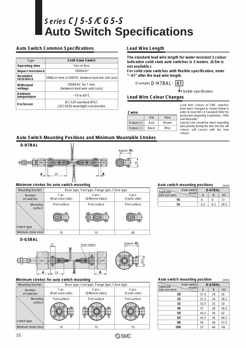
Auto Switch Common Specifications Lead Wire Length
Type
Operating time
Impact resistance
Insulation resistance
Withstand voltage
Ambient temperature
Enclosure
Solid State Switch
1ms or less
1000m/s²
1000VAC for 1 min.(between lead wire and case)
50MΩ or more at 500VDC (between lead wire and case)
–10 to 60°C
IEC529 standard IP67,JISC0920 watertight construction
Lead Wire Colour Changes
D-H7BAL-
Flexible specification
(Example) 61
Output (+)
Output (–)
Old
Red
Black
New
Brown
Blue
2 wire
Lead wire colours of SMC switches have been changed as shown below in order to meet NECA Standard 0402 for production beginning September, 1996 and thereafter.Special care should be taken regarding wire polarity during the time that the old colours still coexist with the new colours.
Auto Switch Mounting Positions and Minimum Mountable Strokes
A
31.5
31.5
32.5
37
45.5
45.5
56
57
20253240506380
100
Mounting bracket
Numberof switches
Minimum stroke (mm)
Mountingsurface
Switch type
Basic type, Foot type, Flange type, Clevis type
1 pc.(Rod cover side)
2 pcs.(Different sides)
2 pcs.(Same side)
10 15 75
Port surface Port surface Port surface
Auto switch mounting positionMinimum strokes for auto switch mounting
Applicable bore size (mm)
Auto switchmodel
B
24
24
25
28
36
36
46
46
D-G5BAL
D-G5BAL
HS
26
28.5
33
36.5
42
48.5
57.5
68
33
12
24.5
Auto switch
BA
Approx. HS
Approx. HS
A
0
0.5
1016
Mounting bracket
Numberof switches
Minimum stroke (mm)
Mountingsurface
Switch type
Basic type, Foot type, Flange type, Clevis type
1 pc.(Rod cover side)
2 pcs.(Different sides)
2 pcs.(Same side)
10 15 60
Port surface Port surface Port surface
Auto switch mounting positionsMinimum strokes for auto switch mounting
Applicable bore size (mm)
Auto switchmodel
B
0
0.5
D-H7BAL
D-H7BAL
HS
17
20.5
16SMC
SMC
29A B
(mm)
(mm)
The standard lead wire length for water resistant 2 colour indication solid state auto switches is 3 meters. (0.5m is not available.)For solid state switches with flexible specification, enter "–61" after the lead wire length.
15
Series CJ5-S/CG5-SAuto Switch Specifications
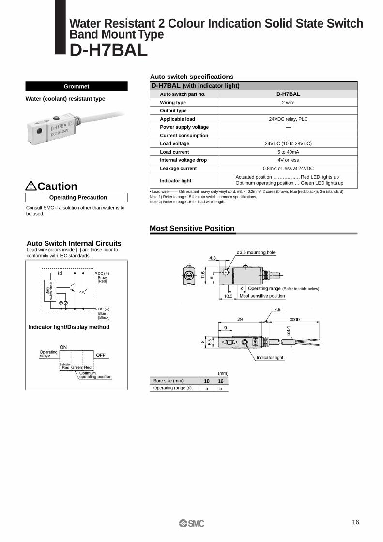
• Lead wire –––– Oil resistant heavy duty vinyl cord, ø3, 4, 0.2mm², 2 cores (brown, blue [red, black]), 3m (standard)Note 1) Refer to page 15 for auto switch common specifications.Note 2) Refer to page 15 for lead wire length.
Auto switch specificationsD-H7BAL (with indicator light)
Auto switch part no.
Wiring type
Output type
Applicable load
Power supply voltage
Current consumption
Load voltage
Load current
Internal voltage drop
Leakage current
Indicator light
D-H7BAL
2 wire
—
24VDC relay, PLC
—
—
24VDC (10 to 28VDC)
5 to 40mA
4V or less
0.8mA or less at 24VDC
Actuated position ………......… Red LED lights upOptimum operating position … Green LED lights up
Grommet
Operating Precaution
Indicator light/Display method
Auto Switch Internal CircuitsLead wire colors inside [ ] are those prior toconformity with IEC standards.
Water (coolant) resistant type
Most Sensitive Position
Caution
Bore size (mm)
Operating range (l )
105
165
(mm)
Mai
nsw
itch
circ
uit
DC (+)Brown[Red]
DC (–)Blue[Black]
Consult SMC if a solution other than water is to be used.
16
Water Resistant 2 Colour Indication Solid State SwitchBand Mount TypeD-H7BAL
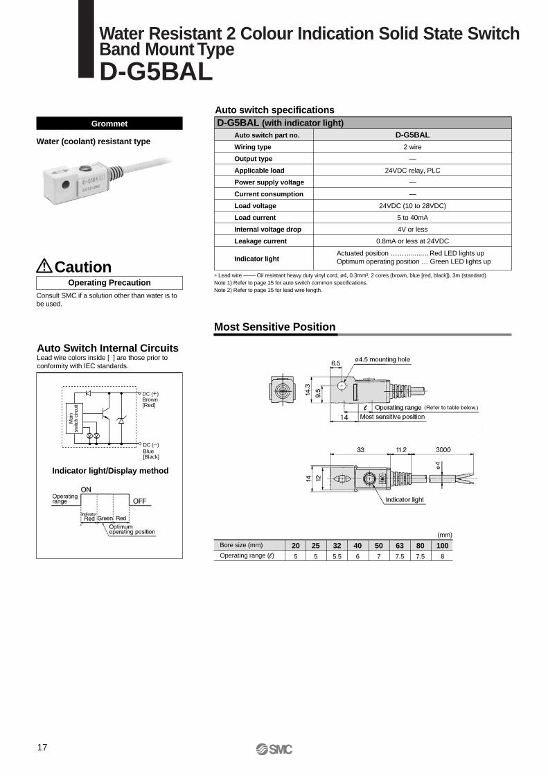
∗ Lead wire –––– Oil resistant heavy duty vinyl cord, ø4, 0.3mm², 2 cores (brown, blue [red, black]), 3m (standard)Note 1) Refer to page 15 for auto switch common specifications.Note 2) Refer to page 15 for lead wire length.
Auto switch specificationsD-G5BAL (with indicator light)
Auto switch part no.
Wiring type
Output type
Applicable load
Power supply voltage
Current consumption
Load voltage
Load current
Internal voltage drop
Leakage current
Indicator light
D-G5BAL
2 wire
—
24VDC relay, PLC
—
—
24VDC (10 to 28VDC)
5 to 40mA
4V or less
0.8mA or less at 24VDC
Actuated position ………......… Red LED lights upOptimum operating position … Green LED lights up
Grommet
Operating Precaution
Auto Switch Internal CircuitsLead wire colors inside [ ] are those prior to conformity with IEC standards.
Water (coolant) resistant type
Consult SMC if a solution other than water is to be used.
Most Sensitive Position
Caution
Bore size (mm)
Operating range (l)
205
255
325.5
406
507
637.5
807.5
1008
(mm)
Mai
nsw
itch
circ
uit
Indicator light/Display method
DC (+)Brown[Red]
DC (–)Blue[Black]
17
Water Resistant 2 Colour Indication Solid State SwitchBand Mount TypeD-G5BAL
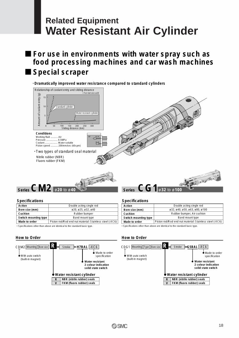
• Two types of standard seal materialNitrile rubber (NBR)Fluoro rubber (FKM)
Relationship of coolant entry and sliding distance
15
10
5
0 50 100 150 200 250 300Sliding distance (km)
Standard cylinder
Water resistant cylinder
∗ For rod size ø20
X
ConditionsWorking fluid ........... AirPressure ................. 0.5MPaCoolant ................... Water-solublePiston speed ........... 200mm/sec (60cpm)
• Dramatically improved water resistance compared to standard cylinders
Am
ount
of c
oola
nt e
ntry
(g)
SpecificationsActionBore size (mm)CushionSwitch mounting typeMade to order
∗ Specifications other than above are identical to the standard basic type.
How to Order
Series CM2 ø20 to ø40
Mounting -XC6Bore sizeCDM2 H7BAL
Water resistant cylinder
Water resistant 2 colour indicationsolid state switch
With auto switch(built-in magnet)
Made to orderspecification
NBR (nitrile rubber) sealsFKM (fluoro rubber) seals
RV
R
Double acting single rodø20, ø25, ø32, ø40
Rubber bumperBand mount type
Piston rod/Rod end nut material: Stainless steel (-XC6)
SpecificationsActionBore size (mm)CushionSwitch mounting typeMade to order
∗ Specifications other than above are identical to the standard basic type.
How to Order
Series CG1
Double acting single rodø32, ø40, ø50, ø63, ø80, ø100
Rubber bumper, Air cushionBand mount type
Piston rod/Rod end nut material: Stainless steel (-XC6)
ø32 to ø100
Water resistant2 colour indicationsolid state switch
With auto switch(built-in magnet)
Made to orderspecification
Mounting -XC6StrokeBore sizeCDG1 G5BALR
Water resistant cylinderNBR (nitrile rubber) sealsFKM (fluoro rubber) seals
RV
TypeStroke
For use in environments with water spray such as food processing machines and car wash machines
Special scraper
18
Related EquipmentWater Resistant Air Cylinder
Specifications
∗ Specifications other than above are identical to the standard basic type.Note 1) Air-hydro type and boot specification of series CA1 are excluded.Note 2) Combination of auto switches and steel tube is not available.
How to Order
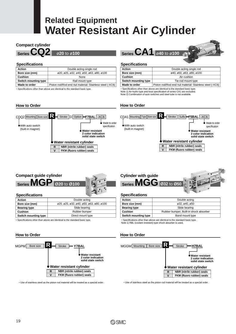
Series CA1
ActionBore size (mm)CushionSwitch mounting typeMade to order
Double acting single rodø40, ø50, ø63, ø80, ø100
Air cushionTie-rod mount type
Piston rod/Rod end nut material: Stainless steel (-XC6)
ø40 to ø100
Water resistant2 color indicationsolid state switch
With auto switch(built-in magnet)
Made to orderspecification
Mounting -XC6StrokeBore sizeCDA1 F5BALR
Water resistant cylinderNBR (nitrile rubber) sealsFKM (fluoro rubber) seals
RV
Type
SpecificationsActionBore size (mm)CushionSwitch mounting typeMade to order
Double acting single rodø20, ø25, ø32, ø40, ø50, ø63, ø80, ø100
NoneRail mount type
Piston rod/Rod end nut material: Stainless steel (-XC6)∗ Specifications other than above are identical to the standard basic type.
How to Order
Water resistant2 color indicationsolid state switch
With auto switch(built-in magnet)
Made to orderspecification
Mounting -XC6StrokeBore sizeCDQ2 F7BALD OptionR
Series CQ2 ø20 to ø100
Water resistant cylinderNBR (nitrile rubber) sealsFKM (fluoro rubber) seals
RV
Compact cylinder
SpecificationsActionBore size (mm)Bearing typeCushionSwitch mounting type
∗ Specifications other than above are identical to the standard basic type.
How to Order
Series MGP Ø20 to Ø100
Double actingø20, ø25, ø32, ø40, ø50, ø63, ø80, ø100
Slide bearingRubber bumper
Direct mount type
∗ Use of stainless steel as the piston rod material will be treated as a special order.
Water resistant2 color indicationsolid state switch
StrokeBore sizeMGPM Y7BALR
Water resistant cylinderNBR (nitrile rubber) sealsFKM (fluoro rubber) seals
RV
Compact guide cylinder
∗ Use of stainless steel as the piston rod material will be treated as a special order.
SpecificationsActionBore size (mm)Bearing typeCushionSwitch mounting type
∗ Specifications other than above are identical to the standard basic type.Note 1) RBL (coolant resistant) type shock absorber is used.
How to Order
Series MGG
Double actingø32, ø40, ø50Slide bearing
Rubber bumper, Built-in shock absorberBand mount type
Water resistant2 color indicationsolid state switch
StrokeBore sizeMGGM H7BALMounting R
Water resistant cylinderNBR (nitrile rubber) sealsFKM (fluoro rubber) seals
RV
Cylinder with guide
Ø32 to Ø50
Suffix
Related EquipmentWater Resistant Air Cylinder
19
--
Applicabletubing O.D.
(mm)
Connectionthreads
3.2
4
6
8
10
12
Model
Meter-out
Elbow type
Meter-in
AS1201FG-M5-23AS2201FG-01-23AS1201FG-M5-04AS2201FG-01-04
-02-04AS1201FG-M5-06AS2201FG-01-06
-02-06AS3201FG-02-06
-03-06AS2201FG-01-08
-02-08AS3201FG-02-08
-03-08AS2201FG-01-10
-02-10AS3201FG-02-10
-03-10AS4201FG-04-10AS3201FG-02-12
-03-12AS4201FG-04-12
AS1211FG-M5-23AS2211FG-01-23AS1211FG-M5-04AS2211FG-01-04
-02-04AS1211FG-M5-06AS2211FG-01-06
-02-06AS3211FG-02-06
-03-06AS2211FG-01-08
-02-08AS3211FG-02-08
-03-08AS2211FG-01-10
-02-10AS3211FG-02-10
-03-10AS4211FG-04-10AS3211FG-02-12
-03-12AS4211FG-04-12
Meter-out
Universal type
Meter-in
AS1301FG-M5-23AS2301FG-01-23AS1301FG-M5-04AS2301FG-01-04
-02-04AS1301FG-M5-06AS2301FG-01-06
-02-06AS3301FG-02-06
-03-06AS2301FG-01-08
-02-08AS3301FG-02-08
-03-08
AS2301FG-02-10AS3301FG-02-10
-03-10AS4301FG-04-10AS3301FG-02-12
-03-12AS4301FG-04-12
AS1311FG-M5-23AS2311FG-01-23AS1311FG-M5-04AS2311FG-01-04
-02-04AS1311FG-M5-06AS2311FG-01-06
-02-06AS3311FG-02-06
-03-06AS2311FG-01-08 -02-08AS3311FG-02-08
-03-08
AS2311FG-02-10AS3311FG-02-10
-03-10AS4311FG-04-10AS3311FG-02-12
-03-12AS4311FG-04-12
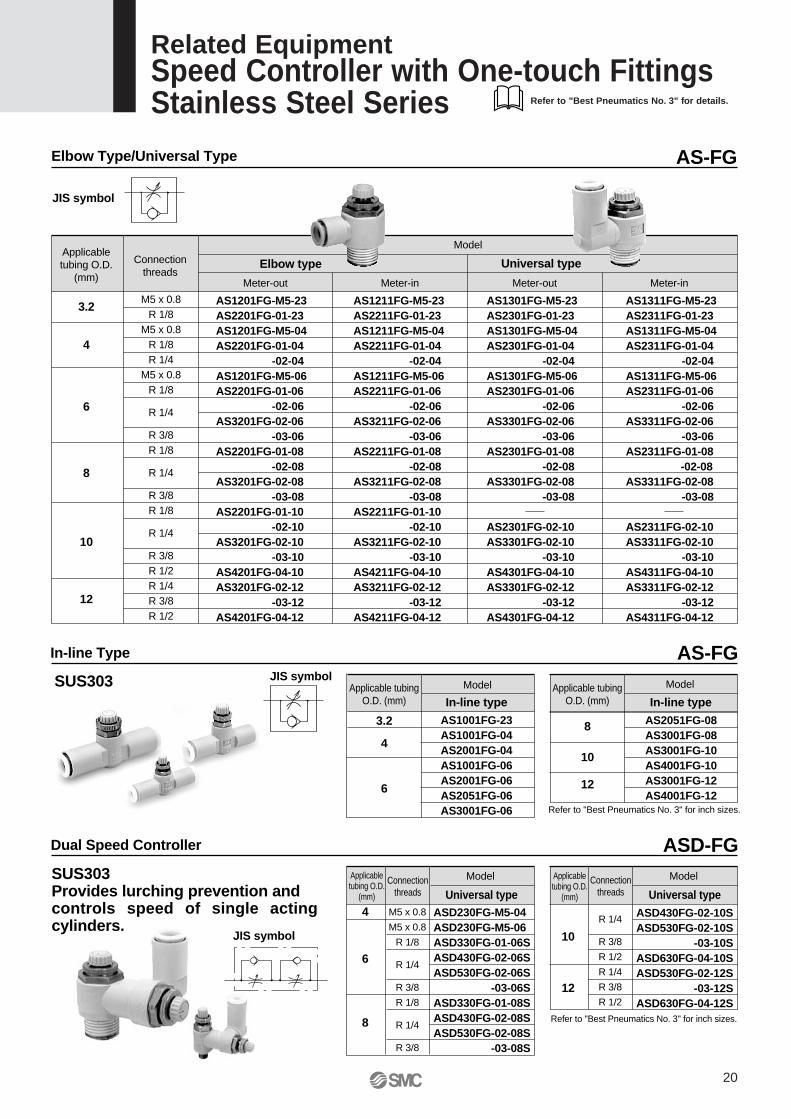
Elbow Type/Universal Type
JIS symbol
AS-FG
M5 x 0.8R 1/8
M5 x 0.8R 1/8R 1/4
M5 x 0.8R 1/8
R 1/4
R 3/8R 1/8
R 1/4
R 3/8R 1/8
R 1/4
R 3/8R 1/2R 1/4R 3/8R 1/2
Dual Speed Controller
Refer to "Best Pneumatics No. 3" for inch sizes.
Applicabletubing O.D.
(mm)
10
12
Model
Universal type
ASD430FG-02-10SASD530FG-02-10S -03-10SASD630FG-04-10SASD530FG-02-12S -03-12SASD630FG-04-12S
Applicabletubing O.D.
(mm)
4
6
8
Model
Universal typeASD230FG-M5-04ASD230FG-M5-06ASD330FG-01-06SASD430FG-02-06SASD530FG-02-06S -03-06SASD330FG-01-08SASD430FG-02-08SASD530FG-02-08S -03-08S
JIS symbol
ASD-FGSUS303 Provides lurching prevention andcontrols speed of single acting cylinders.
M5 x 0.8
M5 x 0.8
R 1/8
R 1/4
R 3/8
R 1/8
R 1/4
R 3/8
R 1/4
R 3/8
R 1/2
R 1/4
R 3/8
R 1/2
Connectionthreads
Connectionthreads
In-line Type AS-FG
Applicable tubingO.D. (mm)
8
10
12
Model
In-line type
AS2051FG-08AS3001FG-08AS3001FG-10AS4001FG-10AS3001FG-12AS4001FG-12
Applicable tubingO.D. (mm)
3.2
4
6
Model
In-line typeAS1001FG-23AS1001FG-04AS2001FG-04AS1001FG-06AS2001FG-06AS2051FG-06AS3001FG-06
SUS303
Refer to "Best Pneumatics No. 3" for inch sizes.
JIS symbol
20
Related EquipmentSpeed Controller with One-touch FittingsStainless Steel Series Refer to "Best Pneumatics No. 3" for details.
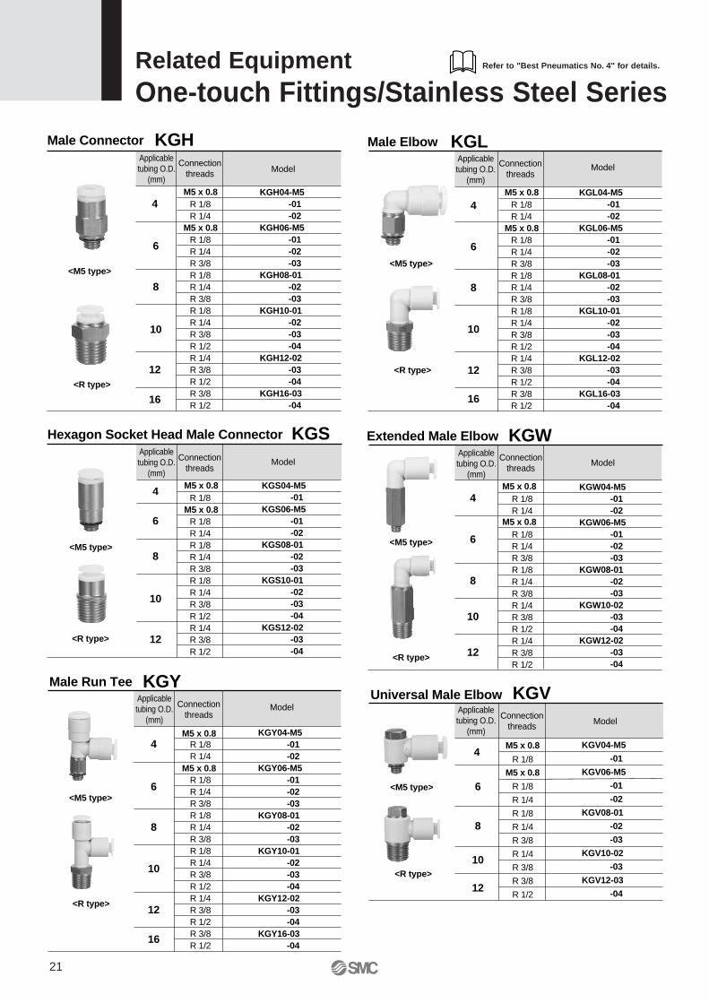
Male Connector
4
6
8
10
12
16
M5 x 0.8
M5 x 0.8
KGH04-M5 -01 -02KGH06-M5 -01 -02 -03KGH08-01 -02 -03KGH10-01 -02 -03 -04KGH12-02 -03 -04KGH16-03 -04
<M5 type>
<R type>
Hexagon Socket Head Male Connector
<M5 type>
<R type>
Applicabletubing O.D.
(mm)
4
6
8
10
12
Connectionthreads
M5 x 0.8
M5 x 0.8
Applicabletubing O.D.
(mm)
Connectionthreads Model
KGS04-M5 -01KGS06-M5 -01 -02KGS08-01 -02 -03KGS10-01 -02 -03 -04KGS12-02 -03 -04
KGS Extended Male Elbow
<M5 type>
<R type>
KGW
KGH Male Elbow
<M5 type>
<R type>
KGLApplicabletubing O.D.
(mm)
4
6
8
10
12
16
Connectionthreads
KGL04-M5 -01 -02KGL06-M5 -01 -02 -03KGL08-01 -02 -03KGL10-01 -02 -03 -04KGL12-02 -03 -04KGL16-03 -04
Applicabletubing O.D.
(mm)
Connectionthreads
4M5 x 0.8
M5 x 0.8
6
8
10
12
KGW04-M5 -01 -02KGW06-M5 -01 -02 -03KGW08-01 -02 -03KGW10-02 -03 -04KGW12-02 -03 -04
Model
Model
Model
R 1/8R 1/4
R 1/8R 1/4R 3/8R 1/8R 1/4R 3/8R 1/8R 1/4R 3/8R 1/2R 1/4R 3/8R 1/2R 3/8R 1/2
R 1/8R 1/4
R 1/8R 1/4R 3/8R 1/8R 1/4R 3/8R 1/4R 3/8R 1/2R 1/4R 3/8R 1/2
R 1/8
R 1/8R 1/4R 1/8R 1/4R 3/8R 1/8R 1/4R 3/8R 1/2R 1/4R 3/8R 1/2
M5 x 0.8
M5 x 0.8
R 1/8R 1/4
R 1/8R 1/4R 3/8R 1/8R 1/4R 3/8R 1/8R 1/4R 3/8R 1/2R 1/4R 3/8R 1/2R 3/8R 1/2
Universal Male Elbow KGV
4
6
8
10
12
M5 x 0.8
M5 x 0.8
KGV04-M5
-01
KGV06-M5
-01
-02
KGV08-01
-02
-03
KGV10-02
-03
KGV12-03
-04
<M5 type>
<R type>
Applicabletubing O.D.
(mm)
Connectionthreads Model
Male Run Tee KGY
<M5 type>
<R type>
Applicabletubing O.D.
(mm)
M5 x 0.8
M5 x 0.8
4
6
8
10
12
16
Connectionthreads
KGY04-M5 -01 -02KGY06-M5 -01 -02 -03KGY08-01 -02 -03KGY10-01 -02 -03 -04KGY12-02 -03 -04KGY16-03 -04
Model
R 1/8
R 1/8
R 1/4
R 1/8
R 1/4
R 3/8
R 1/4
R 3/8
R 3/8
R 1/2
R 1/8R 1/4 R 1/8R 1/4R 3/8R 1/8R 1/4R 3/8R 1/8R 1/4R 3/8R 1/2R 1/4R 3/8R 1/2R 3/8R 1/2
Related EquipmentOne-touch Fittings/Stainless Steel Series
21
Refer to "Best Pneumatics No. 4" for details.
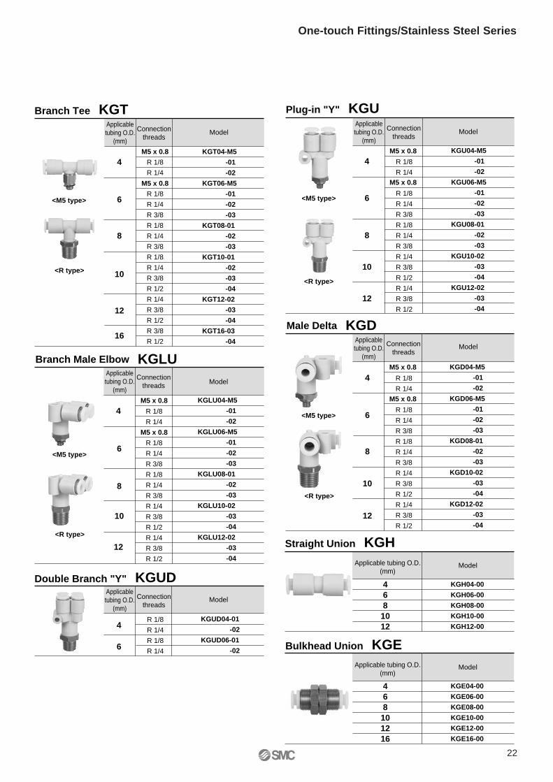
Branch Tee KGT
<M5 type>
<R type>
Applicabletubing O.D.
(mm)
4
6
8
10
12
16
Connectionthreads
M5 x 0.8
M5 x 0.8
KGT04-M5
-01
-02
KGT06-M5
-01
-02
-03
KGT08-01
-02
-03
KGT10-01
-02
-03
-04
KGT12-02
-03
-04
KGT16-03
-04
Plug-in "Y" KGU
<M5 type>
<R type>
Applicabletubing O.D.
(mm)
Connectionthreads
4M5 x 0.8
M5 x 0.8
6
8
10
12
KGU04-M5
-01
-02
KGU06-M5
-01
-02
-03
KGU08-01
-02
-03
KGU10-02
-03
-04
KGU12-02
-03
-04
Model Model
R 1/8
R 1/4
R 1/8
R 1/4
R 3/8
R 1/8
R 1/4
R 3/8
R 1/4
R 3/8
R 1/2
R 1/4
R 3/8
R 1/2
R 1/8
R 1/4
R 1/8
R 1/4
R 3/8
R 1/8
R 1/4
R 3/8
R 1/8
R 1/4
R 3/8
R 1/2
R 1/4
R 3/8
R 1/2
R 3/8
R 1/2
Branch Male Elbow KGLU
4
6
8
10
12
M5 x 0.8
M5 x 0.8
KGLU04-M5
-01
-02
KGLU06-M5
-01
-02
-03
KGLU08-01
-02
-03
KGLU10-02
-03
-04
KGLU12-02
-03
-04
<M5 type>
<R type>
Double Branch "Y" KGUDApplicabletubing O.D.
(mm)
4
6
Connectionthreads
Applicabletubing O.D.
(mm)
Connectionthreads Model
KGUD04-01
-02
KGUD06-01
-02
Straight Union KGH
Male Delta KGD
<M5 type>
<R type>
Applicabletubing O.D.
(mm)
4
6
8
10
12
Connectionthreads
KGD04-M5
-01
-02
KGD06-M5
-01
-02
-03
KGD08-01
-02
-03
KGD10-02
-03
-04
KGD12-02
-03
-04
Applicable tubing O.D.(mm)
468
1012
KGH04-00
KGH06-00
KGH08-00
KGH10-00
KGH12-00
Model
Model
Model
Bulkhead Union KGEApplicable tubing O.D.
(mm)
468
101216
KGE04-00
KGE06-00
KGE08-00
KGE10-00
KGE12-00
KGE16-00
Model
R 1/8
R 1/4
R 1/8
R 1/4
R 3/8
R 1/8
R 1/4
R 3/8
R 1/4
R 3/8
R 1/2
R 1/4
R 3/8
R 1/2
R 1/8
R 1/4
R 1/8
R 1/4
M5 x 0.8
M5 x 0.8
R 1/8
R 1/4
R 1/8
R 1/4
R 3/8
R 1/8
R 1/4
R 3/8
R 1/4
R 3/8
R 1/2
R 1/4
R 3/8
R 1/2
22
One-touch Fittings/Stainless Steel Series
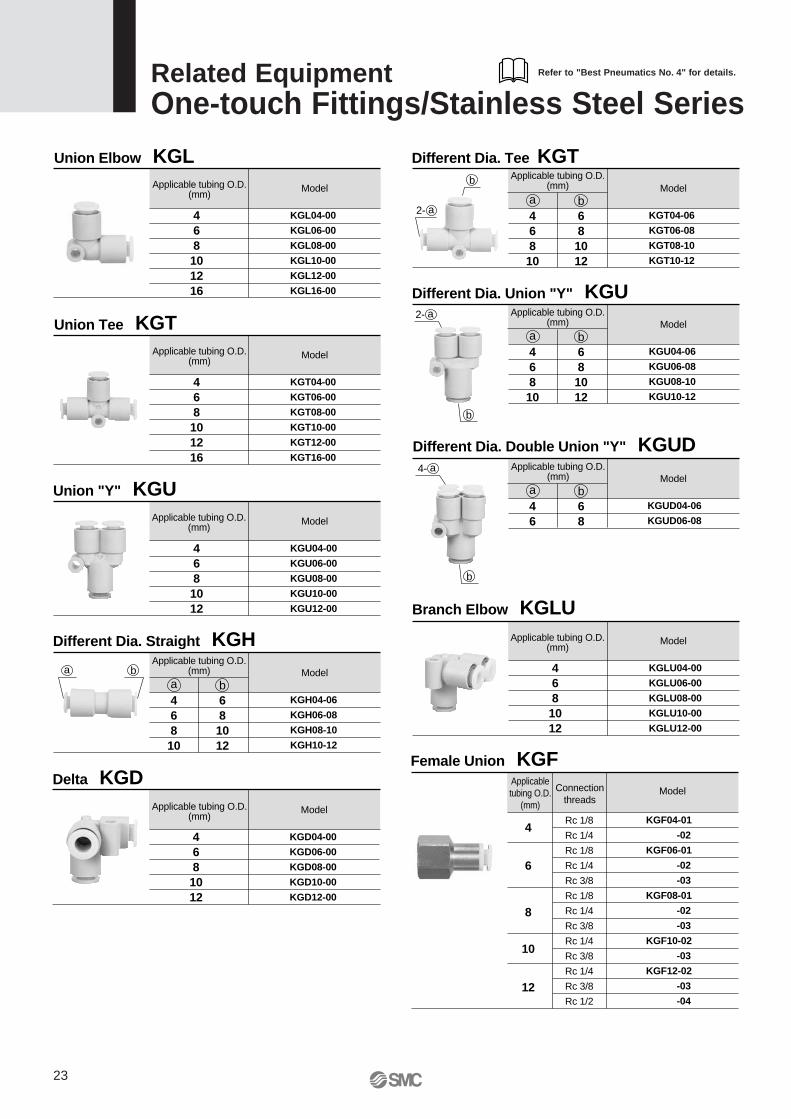
Union Elbow KGLApplicable tubing O.D.
(mm)
468101216
KGL04-00
KGL06-00
KGL08-00
KGL10-00
KGL12-00
KGL16-00
Model
Union Tee KGTApplicable tubing O.D.
(mm)
468101216
KGT04-00
KGT06-00
KGT08-00
KGT10-00
KGT12-00
KGT16-00
Model
Union "Y" KGUApplicable tubing O.D.
(mm)
4681012
KGU04-00
KGU06-00
KGU08-00
KGU10-00
KGU12-00
Model
Branch Elbow KGLUApplicable tubing O.D.
(mm)
4681012
KGLU04-00
KGLU06-00
KGLU08-00
KGLU10-00
KGLU12-00
ModelDifferent Dia. Straight KGHApplicable tubing O.D.
(mm)
KGH04-06
KGH06-08
KGH08-10
KGH10-12
Modela46810
b681012
Different Dia. Tee KGTApplicable tubing O.D.
(mm)
KGT04-06
KGT06-08
KGT08-10
KGT10-12
Modela46810
b681012
Different Dia. Union "Y" KGUApplicable tubing O.D.
(mm)
KGU04-06
KGU06-08
KGU08-10
KGU10-12
Modela46810
b681012
Different Dia. Double Union "Y" KGUDApplicable tubing O.D.
(mm)
KGUD04-06
KGUD06-08
Modela46
b68
a b
4- a
b
2- a
b
2- a
b
Delta KGDApplicable tubing O.D.
(mm)
4681012
KGD04-00
KGD06-00
KGD08-00
KGD10-00
KGD12-00
Model
Female Union KGFApplicabletubing O.D.
(mm)
4
6
8
10
12
Connectionthreads
KGF04-01
-02
KGF06-01
-02
-03
KGF08-01
-02
-03
KGF10-02
-03
KGF12-02
-03
-04
Model
Rc 1/8
Rc 1/4
Rc 1/8
Rc 1/4
Rc 3/8
Rc 1/8
Rc 1/4
Rc 3/8
Rc 1/4
Rc 3/8
Rc 1/4
Rc 3/8
Rc 1/2
Related EquipmentOne-touch Fittings/Stainless Steel Series
23
Refer to "Best Pneumatics No. 4" for details.
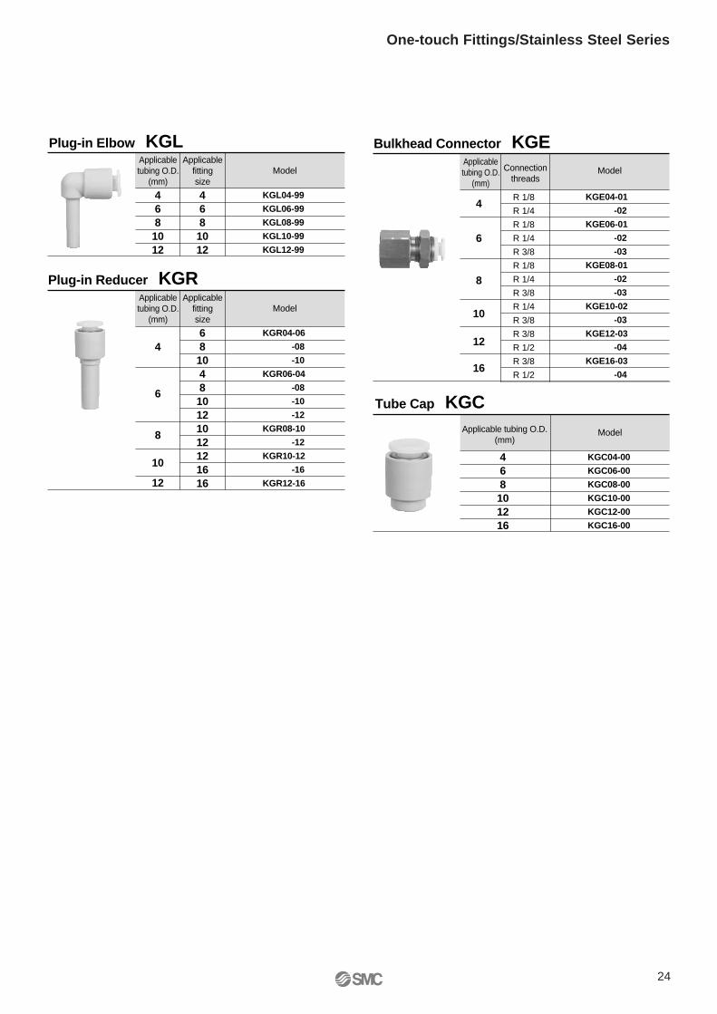
Plug-in Elbow KGLApplicabletubing O.D.
(mm)
4681012
Applicablefittingsize
4681012
KGL04-99
KGL06-99
KGL08-99
KGL10-99
KGL12-99
Model
Plug-in Reducer KGRApplicabletubing O.D.
(mm)
4
6
8
10
12
Applicablefittingsize
68104810121012121616
KGR04-06
-08
-10
KGR06-04
-08
-10
-12
KGR08-10
-12
KGR10-12
-16
KGR12-16
Model
Tube Cap KGCApplicable tubing O.D.
(mm)
468101216
KGC04-00
KGC06-00
KGC08-00
KGC10-00
KGC12-00
KGC16-00
Model
Bulkhead Connector KGEApplicabletubing O.D.
(mm)
4
6
8
10
12
16
Connectionthreads
KGE04-01
-02
KGE06-01
-02
-03
KGE08-01
-02
-03
KGE10-02
-03
KGE12-03
-04
KGE16-03
-04
Model
R 1/8
R 1/4
R 1/8
R 1/4
R 3/8
R 1/8
R 1/4
R 3/8
R 1/4
R 3/8
R 3/8
R 1/2
R 3/8
R 1/2
24
One-touch Fittings/Stainless Steel Series
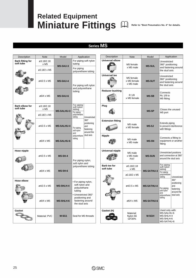
ModelDescription
Barb fitting forsoft tube
For piping soft nylontubing
Application
For piping polyurethane tubing
For piping soft nylonand polyurethanetubing
MS-5AU-3
MS-5AU-4
MS-5AU-6
Barb tee forsoft tube
For pipingsoft nylon andpolyurethanetubing
MS-5ATHU-3
MS-5ATHU-4
MS-5ATHU-6
Barb elbow forsoft tube
Hose nipple
For pipingsoft nylontubingFor pipingpolyurethanetubing
For pipingsoft nylontubingFor pipingpolyurethanetubing
Unrestricted 360°positioning and fastening around the stud axis
Unrestricted 360°positioning andfastening around the stud axis
MS-5ALHU-3
MS-5ALHU-4
MS-5ALHU-6
MS-5H-4
MS-5H-6
Hose elbow
ModelDescription ApplicationNote
ø3.18/2.18 x M5
ø3.18/2 x M5
ø4/2.5 x M5
ø6/4 x M5
ø3.18/2.18 x M5
ø3.18/2 x M5
ø4/2.5 x M5
ø6/4 x M5
ø4/2.5 x M5
ø6/4 x M5
ø4/2.5 x M5
ø6/4 x M5
Material: PVC
MS-5HLH-4
Gasket
Seal for M5 threadsM-5G1
Gasket (H)
M-5GH
Universal nippleUnrestricted positions and connection at 360°around the stud axis
MS-5UN
NippleConnects a fitting to equipment or anotherfitting
MS-5N
Extension fittingExtends pipingto prevent interferencewith fittings
MS-5J
Plug
Closes the unused M5 port
MS-5P
Reducer bushingConnects Rc 1/8 toM5 fitting
MS-5B
Universal tee
MS-5UT
Universal elbow Unrestricted 360° positioning and fastening aroundthe stud axis
Unrestricted 360° positioning and fastening aroundthe stud axis
MS-5UL
MS-5HLH-6
ø3.18/2.18 x M5
ø3.18/2 x M5
ø4/2.5 x M5
ø6/4 x M5
Material:Nylon 66GF30%
Used only with:MS-5ALHU-6MS-5HLH-4MS-5HLH-6MS-5ATHU-6
Note
M5 male x M5 male
PAT
M5 male x M5 female
M5 male x M5 male
R 1/8 x M5 female
M5 female x M5 female x M5 male
M5 female x M5 male
Series MS
For piping nylon, soft nylon and polyurethane tubing
• For piping nylon, soft nylon and polyurethane tubing
• Unrestricted 360° positioning and fastening around the stud axis
For piping soft nylon and polyurethane tubing
Related Equipment
Miniature Fittings
25
Refer to "Best Pneumatics No. 4" for details.
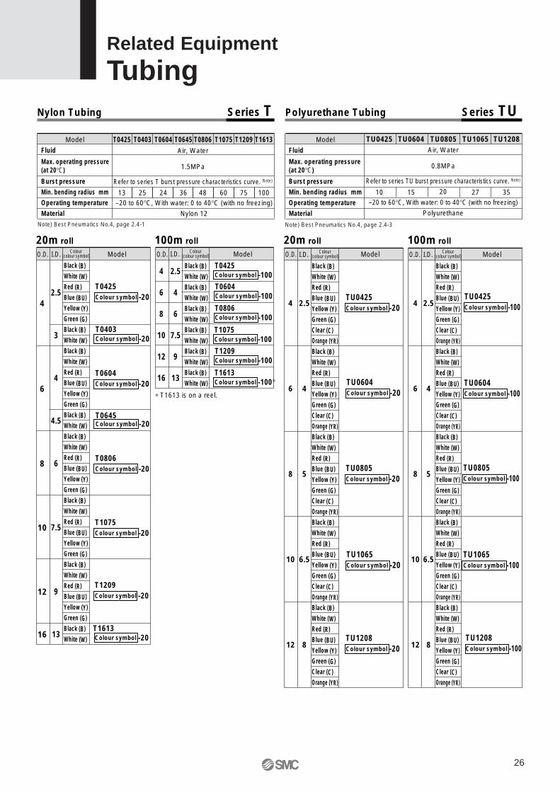
20m roll
2.5
3
4
4.5
6
7.5
9
13
4
6
8
10
12
16
T0425 Colour symbol -20
Black (B)
White (W)
Red (R)
Blue (BU)
Yellow (Y)
Green (G)
Black (B)
White (W)
Black (B)
White (W)
Red (R)
Blue (BU)
Yellow (Y)
Green (G)
Black (B)
White (W)
Black (B)
White (W)
Red (R)
Blue (BU)
Yellow (Y)
Green (G)
Black (B)
White (W)
Red (R)
Blue (BU)
Yellow (Y)
Green (G)
Black (B)
White (W)
Red (R)
Blue (BU)
Yellow (Y)
Green (G)
Black (B)
White (W)
O.D. I.D. Colour(colour symbol) Model
100m roll 20m roll 100m roll
4
6
8
10
12
16
2.5
4
6
7.5
9
13
Black (B)
White (W)
Black (B)
White (W)
Black (B)
White (W)
Black (B)
White (W)
Black (B)
White (W)
Black (B)
White (W)
O.D. I.D. Model
∗ T1613 is on a reel.
Fluid
Max. operating pressure (at 20°C)
Burst pressure
Min. bending radius mm
Operating temperature
Material
Air, Water
1.5MPa
Refer to series T burst pressure characteristics curve. Note)
75604836242513–20 to 60°C, With water: 0 to 40°C (with no freezing)
Nylon 12
100
Nylon Tubing Series T Polyurethane Tubing Series TU
TU0425 Colour symbol -20
TU0805Colour symbol -20
O.D. I.D. Model
Black (B)
White (W)
Red (R)
Blue (BU)
Yellow (Y)
Green (G)
Clear (C)
Orange (YR)
Black (B)
White (W)
Red (R)
Blue (BU)
Yellow (Y)
Green (G)
Clear (C)
Orange (YR)
Black (B)
White (W)
Red (R)
Blue (BU)
Yellow (Y)
Green (G)
Clear (C)
Orange (YR)
Black (B)
White (W)
Red (R)
Blue (BU)
Yellow (Y)
Green (G)
Clear (C)
Orange (YR)
Black (B)
White (W)
Red (R)
Blue (BU)
Yellow (Y)
Green (G)
Clear (C)
Orange (YR)
4
6
8
10
12
2.5
4
5
6.5
8
TU0425 Colour symbol -100
O.D. I.D. Model
Black (B)
White (W)
Red (R)
Blue (BU)
Yellow (Y)
Green (G)
Clear (C)
Orange (YR)
Black (B)
White (W)
Red (R)
Blue (BU)
Yellow (Y)
Green (G)
Clear (C)
Orange (YR)
Black (B)
White (W)
Red (R)
Blue (BU)
Yellow (Y)
Green (G)
Clear (C)
Orange (YR)
Black (B)
White (W)
Red (R)
Blue (BU)
Yellow (Y)
Green (G)
Clear (C)
Orange (YR)
Black (B)
White (W)
Red (R)
Blue (BU)
Yellow (Y)
Green (G)
Clear (C)
Orange (YR)
4
6
8
10
12
2.5
4
5
6.5
8
Fluid
Max. operating pressure (at 20°C)
Burst pressure
Min. bending radius mm
Operating temperature
Material
Air, Water
0.8MPa
Refer to series TU burst pressure characteristics curve. Note)
20
–20 to 60°C, With water: 0 to 40°C (with no freezing)
Polyurethane
10 15 27 35
T1209T1075T0806T0645T0604T0403T0425 T1613 TU0425 TU0604 TU0805 TU1065 TU1208Model Model
T1613 Colour symbol -20
T1209 Colour symbol -20
T1075 Colour symbol -20
T0806 Colour symbol -20
T0645 Colour symbol -20
T0604Colour symbol -20
T0403Colour symbol -20
Colour(colour symbol)
Colour(colour symbol)
Colour(colour symbol)
T0425 Colour symbol -100
T1613 Colour symbol -100∗
T1209 Colour symbol -100
T1075 Colour symbol -100
T0806 Colour symbol -100
T0604 Colour symbol -100
TU0604Colour symbol -100
TU1208 Colour symbol -100
TU1208 Colour symbol -20
TU1065Colour symbol -20
TU1065 Colour symbol -100
TU0805Colour symbol -100
TU0604 Colour symbol -20
Note) Best Pneumatics No.4, page 2.4-1 Note) Best Pneumatics No.4, page 2.4-3
26
Related Equipment
Tubing
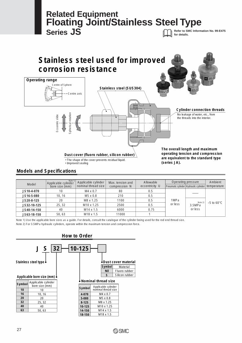
Operating range
Models and Specifications
Centre axisUU
5°5°
Centre of Sphere
Ecc
entr
ic s
lide
Sph
eric
al r
otat
ion
Cylinder connection threadsNo leakage of water, etc., fromthe threads into the interior.
Dust cover (fluoro rubber, silicon rubber)• The shape of the cover prevents residual liquid.• Improved sealing
Stainless steel (SUS304)
Note 1) Use the applicable bore sizes as a guide. For details, consult the catalogue of the cylinder being used for the rod end thread size.Note 2) For 3.5MPa hydraulic cylinders, operate within the maximum tension and compression force.
Ope
ratin
gra
nge
Applicable cylinder bore size (mm)
1010, 16
2025, 32
4050, 63
Applicable cylindernominal thread size
M4 x 0.7M5 x 0.8M8 x 1.25M10 x 1.25M14 x 1.5M18 x 1.5
Max. tension and compression N
8021011002500600011000
Allowable eccentricity U
0.50.50.50.5
0.75 1
Ambient temperature
—
-5 to 60°C
Pneumatic cylinder Hydraulic cylinder
Operating pressure
How to Order
J S 32
Stainless steel type
Symbol
101620324063
Applicable cylinderbore size (mm)
1010, 16
2025, 32
4050, 63
Dust cover materialSymbol
NilS
MaterialFluoro rubberSilicon rubberApplicable bore size (mm)
10-125
Nominal thread size
Symbol
4-0705-0808-12510-12514-15018-150
Applicable cylindernominal thread size
M4 x 0.7M5 x 0.8M8 x 1.25M10 x 1.25M14 x 1.5M18 x 1.5
1MPaor less 3.5MPa
or less
Note 2)
Note 1)
The overall length and maximum operating tension and compression are equivalent to the standard type (series JA).
Stainless steel used for improved corrosion resistance
JS10-4-070JS16-5-080JS20-8-125JS32-10-125JS40-14-150JS63-18-150
Model
Related EquipmentFloating Joint/Stainless Steel TypeSeries JS
27
Refer to SMC Information No. 99-E475 for details.
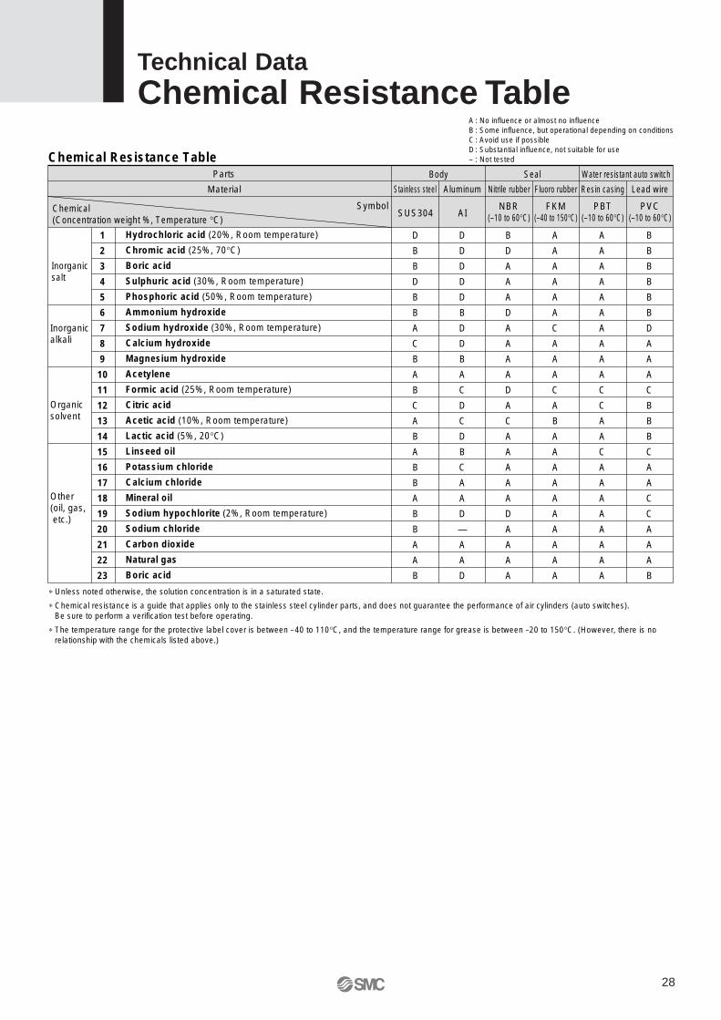
D
B
B
D
B
B
A
C
B
A
B
C
A
B
A
B
B
A
B
B
A
A
B
SUS304
Stainless steel
D
D
D
D
D
B
D
D
B
A
C
D
C
D
B
C
A
A
D
—
A
A
D
AI
Aluminum
Body Seal Water resistant auto switch
B
D
A
A
A
D
A
A
A
A
D
A
C
A
A
A
A
A
D
A
A
A
A
NBR(–10 to 60°C)
Nitrile rubber
A
A
A
A
A
A
C
A
A
A
C
A
B
A
A
A
A
A
A
A
A
A
A
FKM(–40 to 150°C)
Fluoro rubber
A
A
A
A
A
A
A
A
A
A
C
C
A
A
C
A
A
A
A
A
A
A
A
PBT(–10 to 60°C)
Resin casing
B
B
B
B
B
B
D
A
A
A
C
B
B
B
C
A
A
C
C
A
A
A
B
PVC(–10 to 60°C)
Lead wire
Hydrochloric acid (20%, Room temperature)
Chromic acid (25%, 70°C)
Boric acid
Sulphuric acid (30%, Room temperature)
Phosphoric acid (50%, Room temperature)
Ammonium hydroxide
Sodium hydroxide (30%, Room temperature)
Calcium hydroxide
Magnesium hydroxide
Acetylene
Formic acid (25%, Room temperature)
Citric acid
Acetic acid (10%, Room temperature)
Lactic acid (5%, 20°C)
Linseed oil
Potassium chloride
Calcium chloride
Mineral oil
Sodium hypochlorite (2%, Room temperature)
Sodium chloride
Carbon dioxide
Natural gas
Boric acid
1
2
3
4
5
6
7
8
9
10
11
12
13
14
15
16
17
18
19
20
21
22
23
Parts
Material
Chemical(Concentration weight %, Temperature °C)
Symbol
Inorganic salt
Inorganicalkali
Organicsolvent
Other(oil, gas, etc.)
Chemical Resistance Table
A : No influence or almost no influenceB : Some influence, but operational depending on conditionsC: Avoid use if possibleD: Substantial influence, not suitable for use– : Not tested
∗ Unless noted otherwise, the solution concentration is in a saturated state.
∗ Chemical resistance is a guide that applies only to the stainless steel cylinder parts, and does not guarantee the performance of air cylinders (auto switches).Be sure to perform a verification test before operating.
∗ The temperature range for the protective label cover is between –40 to 110°C, and the temperature range for grease is between –20 to 150°C. (However, there is no relationship with the chemicals listed above.)
28
Technical DataChemical Resistance Table
Series CJ5-S/CG5-SSafety Instructions
Note 1) ISO 4414: Pneumatic fluid power -- Recommendations for the application of equipment to transmission and control systems
Note 2) JIS B 8370: General Rules for Pneumatic Equipment
Warning
Caution : Operator error could result in injury or equipment damage.
Warning : Operator error could result in serious injury or loss of life.
Danger : In extreme conditions, there is a possible result of serious injury or loss of life.
These safety instructions are intended to prevent a hazardous situation and/or equipment damage. These instructions indicate the level of potential hazard by a label of "Caution", "Warning" or "Danger". To ensure safety, be sure to observe ISO 4414 Note 1), JIS B 8370 Note 2) and other safety practices.
1. The compatibility of pneumatic equipment is the responsibility of the person who designs the pneumatic system or decides its specifications.Since the products specified here are used in various operating conditions, their compatibility for the specific pneumatic system must be based on specifications or after analysis and/or tests to meet your specific requirements.
2. Only trained personnel should operate pneumatically operated machinery and equipment.Compressed air can be dangerous if handled incorrectly. Assembly, handling or repair of pneumatic systems should be performed by trained and experienced operators.
3. Do not service machinery/equipment or attempt to remove components until safety is confirmed.
1. Inspection and maintenance of machinery/equipment should only be performed after confirmation of safe locked-out control positions.
2. When equipment is to be removed, confirm the safety process as mentioned above. Cut the supply pressure for this equipment and exhaust all residual compressed air in the system.
3. Before machinery/equipment is restarted, take measures to prevent shooting-out of cylinder piston rod, etc. (Bleed air into the system gradually to create back pressure.)
4. Contact SMC if the product is to be used in any of the following conditions:1. Conditions and environments beyond the given specifications, or if product is used outdoors.2. Installation on equipment in conjunction with atomic energy, railway, air navigation, vehicles, medical
equipment, food and beverages, recreation equipment, emergency stop circuits, press applications, or safety equipment.
3. An application which has the possibility of having negative effects on people, property, or animals, requiring special safety analysis.
29
Actuator Common Precautions 1Be sure to read before handling.For detailed individual precautions on each series, refer to the main catalogue sections.
1. Confirm the specifications.The products advertised in this catalog are designed according to use in industrial compressed air systems. If the products are used in conditions where pressure, temperature, etc., are out of specification, damage and/or malfunction may be caused. Do not use in these conditions. (Refer to specifications.)
Consult SMC if you use a fluid other than compressed air.
2. Intermediate stopsWhen intermediate stopping of a cylinder piston is performed with a 3 position closed center type directional control valve, it is difficult to achieve stopping positions as accurate and precise as with hydraulic pressure due to the compressibility of air.
Furthermore, since valves and cylinders, etc., are not guaranteed for zero air leakage, it may not be possible to hold a stopped position for an extended period of time. Contact SMC in case it is necessary to hold a stopped position for an extended period.
1. Operate within the limits of the maximum usable stroke.The piston rod will be damaged if operated beyond the maximum stroke. Refer to the air cylinder model selection procedure for the maximum useable stroke.
2. Operate the piston within a range such that collision damage will not occur at the stroke end.Operate within a range such that damage will not occur when the piston having inertial force stops by striking the cover at the stroke end. Refer to the cylinder model selection procedure for the range within which damage will not occur.
3. Use a speed controller to adjust the cylinder drive speed, gradually increasing from a low speed to the desired speed setting.
4. Provide intermediate supports for long stroke cylinders.Provide intermediate supports for cylinders with long strokes to prevent rod damage due to sagging of the rod, deflection of the tube, vibration and external loads, etc.
Design Selection
Warning Warning
Caution
1. There is a danger of sudden action by air cylinders if sliding parts of machinery are twisted, etc., and changes in forces occur. In such cases, human injury may occur; e.g., by catching hands or feet in the machinery, or damage to the machinery itself may occur. Therefore, the machine should be designed to avoid such dangers.
2. Install a protective cover when there is a risk of human injury.If a driven object and moving parts of a cylinder pose a danger of human injury, design the structure to avoid contact with the human body.
3. Securely tighten all stationary parts and connected parts so that they will not become loose.Especially when a cylinder operates with high frequency or is installed where there is a lot of vibration, ensure that all parts remain secure.
4. A deceleration circuit may be required.When a driven object is operated at high speed or the load is heavy, a cylinder’s cushion will not be sufficient to absorb the impact. Install a deceleration circuit to reduce the speed before cushioning to relieve the impact. In this case, the rigidity of the machinery should also be examined.
5. Consider a possible drop in operating pressure due to a power outage, etc.When a cylinder is used in a clamping mechanism, there is a danger of work pieces dropping if there is a decrease in clamping force due to a drop in circuit pressure caused by a power outage, etc. Therefore, safety equipment should be installed to prevent damage to machinery and/or human injury. Suspension mechanisms and lifting devices also require consideration for drop prevention.
6. Consider a possible loss of power source.Measures should be taken to protect against human injury and equipment damage in the event that there is a loss of power to equipment controlled by air pressure, electricity or hydraulics, etc.
7. Design circuitry to prevent sudden lurching of driven objects.When a cylinder is driven by an exhaust center type directional control valve or when starting up after residual pressure is exhausted from the circuit, etc., the piston and its driven object will lurch at high speed if pressure is applied to one side of the cylinder because of the absence of air pressure inside the cylinder. Therefore, select equipment and design circuits to prevent sudden lurching, because there is a danger of human injury and/or damage to equipment when this occurs.
8. Consider emergency stops.Design so that human injury and/or damage to machinery and equipment will not be caused when machinery is stopped by a safety device under abnormal conditions, such as a power outage or a manual emergency stop.
9. Consider the action when operation is restarted after an emergency stop or abnormal stop.Design the machinery so that human injury or equipment damage will not occur upon restart of operation. When the cylinder has to be reset at the starting position, install safe manual control equipment.
30
Actuator Common Precautions 2Be sure to read before handling.For detailed individual precautions on each series, refer to the main catalogue sections.
31
1. Be certain to align the rod axis with the load and direction of movement when connecting.When not properly aligned, the rod and tube may be twisted, and damage may be caused due to wear on areas such as the inner tube surface, bushings, rod surface and seals.
2. When an external guide is used, connect the rod end and the load in such a way that there is no interference at any point within the stroke.
3. Do not scratch or gouge the sliding parts of the cylinder tube or piston rod, etc., by striking or grasping them with other objects.Cylinder bores are manufactured to precise tolerances, so that even a slight deformation may cause malfunction. Also, scratches or gouges, etc., in the piston rod may lead to damaged seals and cause air leakage.
4. Prevent the seizure of rotating parts.Prevent the seizure of rotating parts (pins, etc.) by applying grease.
5. Do not use until you can verify that equipment can operate properly.Verify correct mounting by appropriate function and leakage inspections after compressed air and power are connected following mounting, maintenance or conversions.
6. Instruction manualThe product should be mounted and operated after thoroughly reading the manual and understanding its contents.
Keep the instruction manual where it can be referred to as needed.
1. Preparation before pipingBefore piping is connected, it should be thoroughly blown out with air (flushing) or washed to remove chips, cutting oil and other debris from inside the pipe.
2. Wrapping of pipe tapeWhen screwing together pipes and fittings, etc., be certain that chips from the pipe threads and sealing material do not get inside the piping.
Also, when pipe tape is used, leave 1.5 to 2 thread ridges exposed at the end of the threads.
Cushion
1. Readjust using the cushion needle.Cushion is adjusted at the factory, however, the cushion needle on the cover should be readjusted when the product is put into service, based upon factors such as the size of the load and the operating speed. When the cushion needle is turned clockwise, the restriction becomes smaller and the cushion's effectiveness is increased. Tighten the lock nut securely after adjustment is performed.
2. Do not operate with the cushion needle in a fully closed condition.This will cause damage to the seals.
Caution
Caution
Mounting
Wrapping direction
Pipe tape
Expose approx. 2 threads
1. Use clean air.Do not use compressed air which includes chemicals, synthetic oils containing organic solvents, salt or corrosive gases, etc., as it can cause damage or malfunction.
1. Install air filters.Install air filters at the upstream side of valves. The filtration degree should be 5µm or finer.
2. Install an after cooler, air dryer or water separator, etc.Air that includes excessive drainage may cause malfunction of valves and other pneumatic equipment. To prevent this, install an after cooler, air dryer or water separator, etc.
3. Use the product within the specified range of fluid and ambient temperature.Take measures to prevent freezing, since moisture in circuits can be frozen under 5°C, and this may cause damage to seals and lead to malfunction.
Refer to SMC’s “Air Cleaning Equipment” catalog for further details on compressed air quality.
WarningAir Supply
Caution
Caution
Piping
Maintenance
Warning1. Removal of equipment, and supply/exhaust
of compressed air.When equipment is removed, first check measures to prevent dropping of driven objects and run-away of equipment, etc. Then cut off the supply pressure and electric power, and exhaust all compressed air from the system.
When machinery is restarted, proceed with caution after confirming measures to prevent cylinder lurching.
1. Drain flushingRemove drainage from air filters regularly. (Refer to specifications.)
Caution
1. Note the weight of the stainless steel products.Since the weight of stainless steel cylinders is approximately 1.5 to 3 times heavier than the standard products (with aluminum body), be careful when calculating weight estimates. Also, when mounting the cylinder on equipment where vibration is expected, avoid using single side brackets such as the flange type, and use double side brackets such as the foot type instead.
1. Fully consider the compatibility of stainless steel.The corrosion resistance of stainless steel is not effective against all media and corrosive environments. Corrosion proceeds rapidly with strong hydrochloric acid, hydrofluoric acid, and high temperature ammonium gas, etc. Therefore its compatibility to the environment must be considered carefully.
2. Do not operate cylinders with auto switches in environments where oil and chemicals are used.Contact SMC when operating in environments with coolants, cleaning solvents, various oils or chemicals, as it may cause adverse effects (faulty insulation, malfunction due to swelling of the potting resin, and hardening of lead wires, etc) to auto switches even in a short period of time. Even with the fluoro rubber seal specification, the auto switch related parts (switch body, mounting bracket, and built-in magnet) are identical to the standard specifications. Therefore, consult SMC regarding the cylinder's compatibility (such as chemical resistance) with an environment (chemicals, etc.) before operating.
3. Do not immerse the cylinder in water or chemicals.When the cylinder is operated in a condition with water pressure, the fluid leaks into the cylinder in the early stages. In the worst case, the fluid may back flow inside the piping and damage the solenoid valve.
Operating EnvironmentDesign
Warning Warning
1. If there is a reduction in grease lubrication and reapplication of grease is necessary, use the special grease shown below.Grease kit part no. for stainless steel cylinders• GR-R-010 (10g)
Precautions for series CG5-S1. Sealant∗ is used on the threads of the
connecting sections of the cover and the cylinder tube for air-tight construction. When disassembling the cylinder, the old sealant must be completely removed, and new sealant must be applied before re-assembling.∗ Loctite 542 (medium strength) or equivalent
2. ø50 or larger bore size cylinders cannot be disassembled.When disassembling cylinders with bore sizes of ø20 through ø40, grip the double flat part of either the head cover or the rod cover with a vise and loosen the other side with a wrench or a monkey wrench, etc., and then remove the cover. When re-tightening, tighten approximately 2 degrees more than the original position. (Cylinders with ø50 or larger bore sizes are tightened with a large tightening torque and cannot be disassembled. Contact SMC when disassembly is required.)
Maintenance
CautionMounting
Warning
1. Generally, use nitrile rubber (NBR) seals with liquids that do not contain chlorine and sulphur, and use fluoro rubber (FKM) seals with liquids that contain chlorine and sulphur.However, depending on the type and the brand of liquid (such as cleaning solvent) that splashes on the cylinder, the operating life of seals may be reduced dramatically. In cases where special additives are used, or where liquid caused trouble with the conventional nitrile or fluoro rubber seals in the past, request an investigation or set up a test period for the use of the seals.
2. Even the fluoro rubber specification may not be applicable depending on the type of chemicals and the operating temperature. Therefore, be sure to verity the seal's applicability before use.
Selection
Warning
1. Do not rotate the cover.If the cover is rotated when the cylinder is mounted or when fittings are screwed in, it may cause damage from the joint section of the cover.
32
Stainless Steel Cylinder Series CJ5-S/CG5-SSpecific Product PrecautionsBe sure to read before handling. Refer to pages 29 through 31 for safety instructions and actuator common precautions.
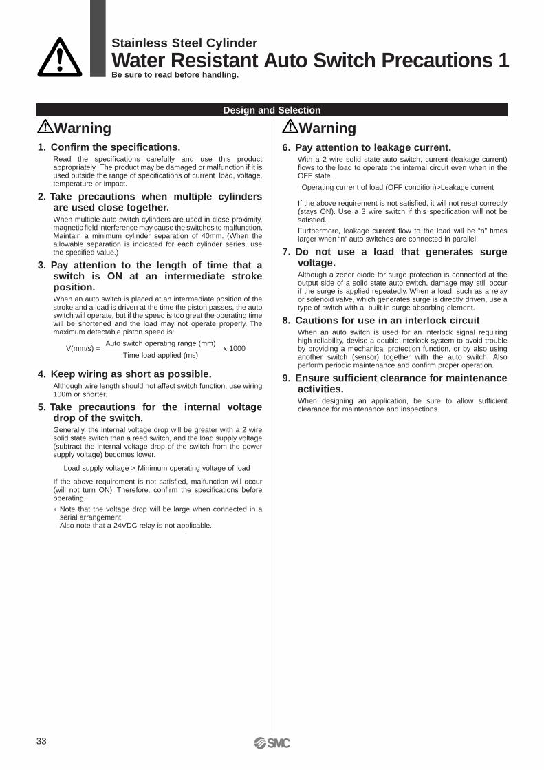
Stainless Steel Cylinder
Water Resistant Auto Switch Precautions 1Be sure to read before handling.
33
1. Confirm the specifications.Read the specifications carefully and use this product appropriately. The product may be damaged or malfunction if it is used outside the range of specifications of current load, voltage, temperature or impact.
2. Take precautions when multiple cylinders are used close together.When multiple auto switch cylinders are used in close proximity, magnetic field interference may cause the switches to malfunction. Maintain a minimum cylinder separation of 40mm. (When the allowable separation is indicated for each cylinder series, use the specified value.)
3. Pay attention to the length of time that a switch is ON at an intermediate stroke position.When an auto switch is placed at an intermediate position of the stroke and a load is driven at the time the piston passes, the auto switch will operate, but if the speed is too great the operating time will be shortened and the load may not operate properly. The maximum detectable piston speed is:
4. Keep wiring as short as possible.Although wire length should not affect switch function, use wiring 100m or shorter.
5. Take precautions for the internal voltage drop of the switch.Generally, the internal voltage drop will be greater with a 2 wire solid state switch than a reed switch, and the load supply voltage (subtract the internal voltage drop of the switch from the power supply voltage) becomes lower.
Load supply voltage > Minimum operating voltage of load
If the above requirement is not satisfied, malfunction will occur (will not turn ON). Therefore, confirm the specifications before operating.
∗ Note that the voltage drop will be large when connected in a serial arrangement.Also note that a 24VDC relay is not applicable.
Design and Selection
WarningWarning6. Pay attention to leakage current.
With a 2 wire solid state auto switch, current (leakage current) flows to the load to operate the internal circuit even when in the OFF state.
If the above requirement is not satisfied, it will not reset correctly (stays ON). Use a 3 wire switch if this specification will not be satisfied.
Furthermore, leakage current flow to the load will be “n” times larger when “n” auto switches are connected in parallel.
7. Do not use a load that generates surge voltage.Although a zener diode for surge protection is connected at the output side of a solid state auto switch, damage may still occur if the surge is applied repeatedly. When a load, such as a relay or solenoid valve, which generates surge is directly driven, use a type of switch with a built-in surge absorbing element.
8. Cautions for use in an interlock circuitWhen an auto switch is used for an interlock signal requiring high reliability, devise a double interlock system to avoid trouble by providing a mechanical protection function, or by also using another switch (sensor) together with the auto switch. Also perform periodic maintenance and confirm proper operation.
9. Ensure sufficient clearance for maintenance activities.When designing an application, be sure to allow sufficient clearance for maintenance and inspections.
Operating current of load (OFF condition)>Leakage current
Auto switch operating range (mm)____________________________Time load applied (ms)
V(mm/s) = x 1000
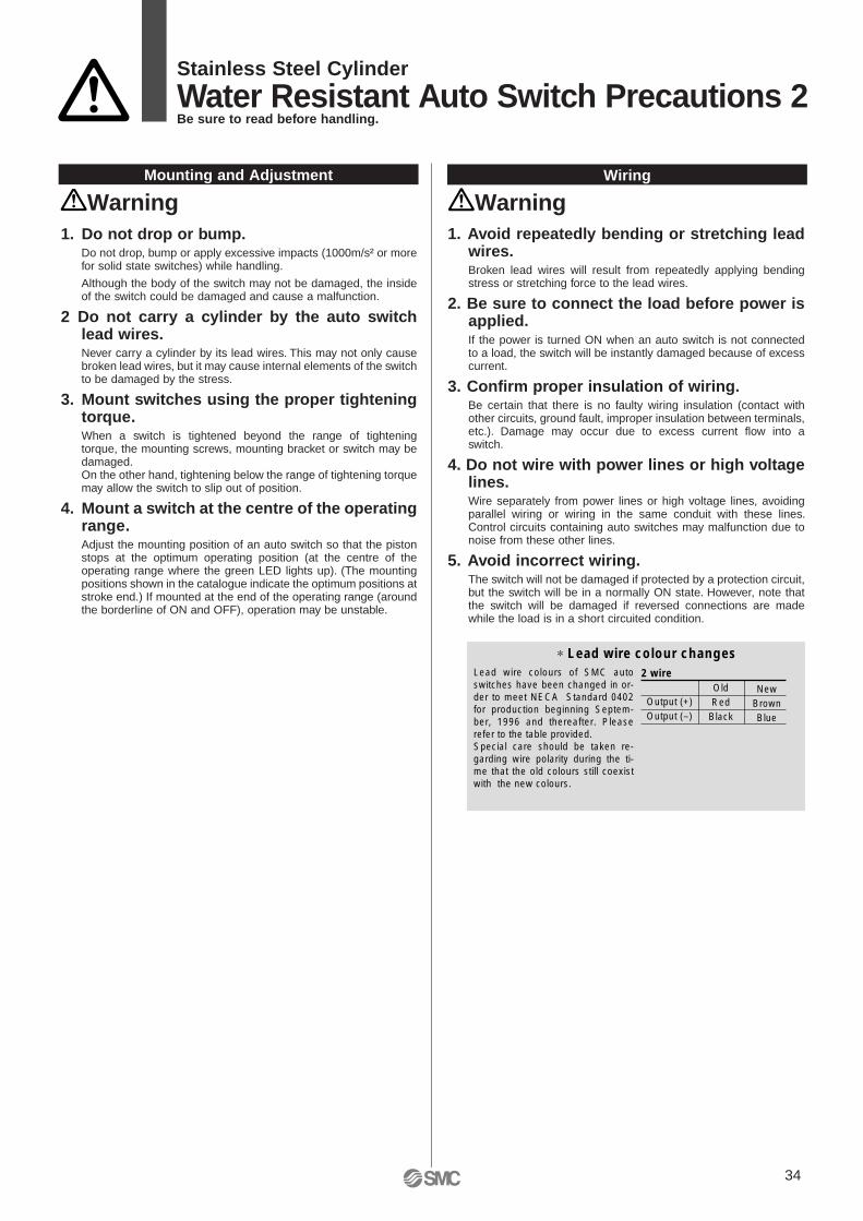
Stainless Steel Cylinder
Water Resistant Auto Switch Precautions 2Be sure to read before handling.
1. Do not drop or bump.Do not drop, bump or apply excessive impacts (1000m/s² or more for solid state switches) while handling.
Although the body of the switch may not be damaged, the inside of the switch could be damaged and cause a malfunction.
2 Do not carry a cylinder by the auto switch lead wires.Never carry a cylinder by its lead wires. This may not only cause broken lead wires, but it may cause internal elements of the switch to be damaged by the stress.
3. Mount switches using the proper tightening torque.When a switch is tightened beyond the range of tightening torque, the mounting screws, mounting bracket or switch may be damaged.On the other hand, tightening below the range of tightening torque may allow the switch to slip out of position.
4. Mount a switch at the centre of the operating range.Adjust the mounting position of an auto switch so that the piston stops at the optimum operating position (at the centre of the operating range where the green LED lights up). (The mounting positions shown in the catalogue indicate the optimum positions at stroke end.) If mounted at the end of the operating range (around the borderline of ON and OFF), operation may be unstable.
Mounting and Adjustment Wiring
Warning1. Avoid repeatedly bending or stretching lead
wires.Broken lead wires will result from repeatedly applying bending stress or stretching force to the lead wires.
2. Be sure to connect the load before power is applied.If the power is turned ON when an auto switch is not connected to a load, the switch will be instantly damaged because of excess current.
3. Confirm proper insulation of wiring.Be certain that there is no faulty wiring insulation (contact with other circuits, ground fault, improper insulation between terminals, etc.). Damage may occur due to excess current flow into a switch.
4. Do not wire with power lines or high voltage lines.Wire separately from power lines or high voltage lines, avoiding parallel wiring or wiring in the same conduit with these lines. Control circuits containing auto switches may malfunction due to noise from these other lines.
5. Avoid incorrect wiring.The switch will not be damaged if protected by a protection circuit, but the switch will be in a normally ON state. However, note that the switch will be damaged if reversed connections are made while the load is in a short circuited condition.
OldRed
Black
NewBrownBlue
Output (+)Output (–)
2 wire
∗ Lead wire colour changes Lead wire colours of SMC auto switches have been changed in or-der to meet NECA Standard 0402 for production beginning Septem-ber, 1996 and thereafter. Please refer to the table provided.Special care should be taken re-garding wire polarity during the ti-me that the old colours still coexist with the new colours.
Warning
34
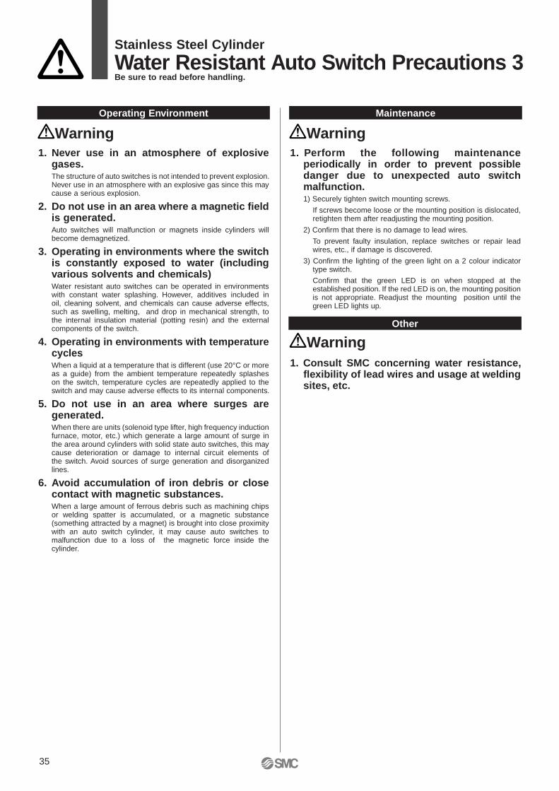
Stainless Steel Cylinder
Water Resistant Auto Switch Precautions 3Be sure to read before handling.
35
1. Never use in an atmosphere of explosive gases. The structure of auto switches is not intended to prevent explosion. Never use in an atmosphere with an explosive gas since this may cause a serious explosion.
2. Do not use in an area where a magnetic field is generated.Auto switches will malfunction or magnets inside cylinders will become demagnetized.
3. Operating in environments where the switch is constantly exposed to water (including various solvents and chemicals)Water resistant auto switches can be operated in environments with constant water splashing. However, additives included in oil, cleaning solvent, and chemicals can cause adverse effects, such as swelling, melting, and drop in mechanical strength, to the internal insulation material (potting resin) and the external components of the switch.
4. Operating in environments with temperature cycles When a liquid at a temperature that is different (use 20°C or more as a guide) from the ambient temperature repeatedly splashes on the switch, temperature cycles are repeatedly applied to the switch and may cause adverse effects to its internal components.
5. Do not use in an area where surges are generated.When there are units (solenoid type lifter, high frequency induction furnace, motor, etc.) which generate a large amount of surge in the area around cylinders with solid state auto switches, this may cause deterioration or damage to internal circuit elements of the switch. Avoid sources of surge generation and disorganized lines.
6. Avoid accumulation of iron debris or close contact with magnetic substances.When a large amount of ferrous debris such as machining chips or welding spatter is accumulated, or a magnetic substance (something attracted by a magnet) is brought into close proximity with an auto switch cylinder, it may cause auto switches to malfunction due to a loss of the magnetic force inside the cylinder.
Operating Environment Maintenance
WarningWarning1. Perform the following maintenance
periodically in order to prevent possible danger due to unexpected auto switch malfunction.1) Securely tighten switch mounting screws.
If screws become loose or the mounting position is dislocated, retighten them after readjusting the mounting position.
2) Confirm that there is no damage to lead wires.
To prevent faulty insulation, replace switches or repair lead wires, etc., if damage is discovered.
3) Confirm the lighting of the green light on a 2 colour indicator type switch.
Confirm that the green LED is on when stopped at the established position. If the red LED is on, the mounting position is not appropriate. Readjust the mounting position until the green LED lights up.
Other
Warning1. Consult SMC concerning water resistance,
flexibility of lead wires and usage at welding sites, etc.

SMC CORPORATION 1-16-4 Shimbashi, Minato-ku, Tokio 105 JAPAN; Phone:03-3502-2740 Fax:03-3508-2480
© DiskArt™ 1988
© DiskArt™ UKSMC Pneumatics (UK) LtdVincent Avenue, Crownhill,Milton Keynes, MK8 0ANPhone: 01908-563888 Fax: 01908-561185
AustriaSMC Pneumatik GmbH (Austria).Girakstrasse 8, A-2100 KorneuburgPhone: 02262-62280, Fax: 02262-62285
CzechSMC Czech.s.r.o.Kodanska 46, CZ-100 10 Prague 10Phone: 02-67154 790, Fax: 02-67154 793
PortugalSMC España (Sucursal Portugal), S.A.Rua de Engº Ferreira Dias 452, 4100 PortoPhone: 02-610-89-22, Fax: 02-610-89-36
BelgiumSMC Pneumatics N.V./S.A.Nijverheidsstraat 20, B-2160 WommelgemPhone: 03-355-1464, Fax: 03-355-1466
LithuaniaUAB Ottensten LietuvaSavanoriu pr.180, LT-2600 Vilnius, LithuaniaPhone/Fax: 370-2651602
LatviaOttensten Latvia SIACiekurkalna Prima Gara Linija 11,LV-1026 Riga, LatviaPhone: 371-23-68625, Fax: 371-75-56748
Denmark
SwedenSMC Pneumatics Sweden A.B.Ekhagsvägen 29-31, S-14105 HuddingePhone: 08-603 07 00, Fax: 08-603 07 10
FranceSMC Pneumatique, S.A.1, Boulevard de Strasbourg, Parc Gustave EiffelBussy Saint GeorgesF-77607 Marne La Vallee Cedex 3Phone: 01-6476 1000, Fax: 01-6476 1010
FinlandSMC Pneumatiikka OYVeneentekijäntie 7, SF-00210 HelsinkiPhone: 09-681021, Fax: 09-6810233
EstoniaTeknoma Eesti ASMustamäe tee 5, EE-0006 Tallinn, EstoniaPhone: 259530, Fax: 259531
GreeceS. Parianopoulus S.A.9, Konstantinoupoleos Street,GR-11855 AthensPhone: 01-3426076, Fax: 01-3455578
TurkeyEntek Pnömatik San. ve Tic Ltd. Sti.Perpa Tic. Merkezi Kat: 11 No: 1625,TR-80270 Okmeydani IstanbulPhone: 0212-221-1512, Fax: 0212-220-2381
PolandSemac Co., Ltd.PL-05-075 Wesola k/Warszaway, ul. Wspolna 1APhone: 022-6131847, Fax: 022-613-3028
NetherlandsSMC Pneumatics BVPostbus 308, 1000 AH AmsterdamPhone: 020-5318888, Fax: 020-5318880
IrelandSMC Pneumatics (Ireland) Ltd.2002 Citywest Business Campus,Naas Road, Saggart, Co. DublinPhone: 01-403 9000, Fax: 01-464 0500
SpainSMC España, S.A.Zuazobidea 14, Pol. Ind. Jundiz,E-01015 VitoriaPhone: 945-184 100, Fax: 945-184 124
HungarySMC Hungary Kft.Budafoki ut 107-113, 1117 BudapestPhone: 01-204 4366, Fax: 01-204 4371
Russia
SwitzerlandSMC Pneumatik AGDorfstrasse 7, CH-8484 WeisslingenPhone: 052-396-3131, Fax: 052-396-3191
ItalySMC Italia S.p.AVia Garibaldi 62, I-20061 Carugate, (Milano)Phone: 02-92711, Fax: 02-92150394
GermanySMC Pneumatik GmbHBoschring 13-15, D-63329 EgelsbachPhone: 06103-4020, Fax: 06103-402139
Norway
SloveniaSMC Slovenia d.o.o.Grajski trg 15, 8360 ZuzemberkPhone: 068-88 044 Fax: 068-88 041
SlovakiaSMC Slovakia s.r.o.Pribinova ul. C. 25, 819 02 BratislavaPhone: 0-563 3548, Fax: 07-563 3551
RomaniaSMC Romania srlVasile Stroescu 19, Sector 2, BucharestPhone: 01-210-1354 , Fax: 01-210-1680
Specifications are subject to change without prior noticeand any obligation on the part of the manufacturer.
SMC UK Contact Numbers
BirminghamJAMES LISTERTel: 0121 5803800Fax: 0121 5535951
BlackburnBLACKBURN PNEUMATIC SYSTEMS LTDTel: 01254 682232Fax: 01254 682224
SMC UK Sales PartnersBristolAPPLIED AUTOMATIONTel: 0117 9827769Fax: 0117 9235522
Bury St EdmundsPNEUMATIC LINESTel: 01284 706239Fax: 01284 761218
CardiffWALES FLUID POWERTel: 02920 494551Fax: 02920 481955
PlymouthAPPLIED AUTOMATIONTel: 01752 343300Fax: 01752 341161
ARGENTINA, AUSTRALIA, BOLIVIA, BRASIL, CANADA, CHILE, CHINA, HONG KONG, INDIA, MALAYSIA, MEXICO, NEW ZEALAND,PHILIPPINES, SINGAPORE, SOUTH KOREA, TAIWAN, THAILAND, USA, VENEZUELA
OTHER SUBSIDIARIES WORLDWIDE:
THE NATIONAL SALES CENTRE FOR ENGLAND & WALES Internal Sales
(Price, Delivery Information & Order Placement)Freephone: 0800 138 2930 Fax: 01908 555064
e-mail:[email protected]
Customer Services (Post-Order Resolution)
Freephone: 0800 138 2931 Fax: 01908 555065 e-mail: [email protected]
Head Office: SMC Pneumatics (UK) Ltd, Vincent Avenue, Crownhill, Milton Keynes MK8 0AN
SMC SALES CENTRE FOR SCOTLAND & N. IRELAND Tel: 01236 781133 Fax: 01236 780611
SMC Pneumatics (UK) Ltd, 1 Carradale Crescent, Broadwood Business Park, Cumbernauld, Glasgow G69 9LE
TECHNICAL CENTREFreephone: 0800 138 2932 Fax: 01908 555066
e-mail: [email protected]
SMC FAST RESPONSE(Literature & Catalogue Requests)
0800 0262006
SMC Pneumatics Norway ASVollsveien 13 C, Granfoss NæringsparkN-1324 LysakerTel: (47) 67 12 90 20, Fax: (47) 67 12 90 21
SMC Pneumatik LLC.36/40 Sredny pr. St. Petersburg 199004Phone.:(812) 118 5445, Fax:(812) 118 5449
SMC Pneumatik Knudsminde 4B, DK-8300 OdderPhone: (45)70252900, Fax: (45)70252901
2000/10/01