Embed Size (px)
Citation preview

STAINLESSSTEEL
STAINLESS STEEL GEARING SOLUTIONS CONEDRIVE.COM STAINLESS STEEL GEARING SOLUTIONS CONEDRIVE.COM Sales: 1-888-994-2663Sales Fax: 1-888-907-2663Traverse City, MI. 49685
Cone Drive reserves the right to improve or change product design and specifications without notice.
2
Stainless Steel Diagram
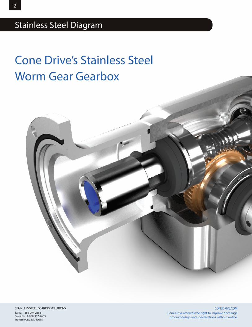
Cone Drive’s Stainless Steel Worm Gear Gearbox
STAINLESS STEEL GEARING SOLUTIONS CONEDRIVE.COM STAINLESS STEEL GEARING SOLUTIONS CONEDRIVE.COM Sales: 1-888-994-2663Sales Fax: 1-888-907-2663Traverse City, MI. 49685
Cone Drive reserves the right to improve or change product design and specifications without notice.
3
Stainless Steel Diagram
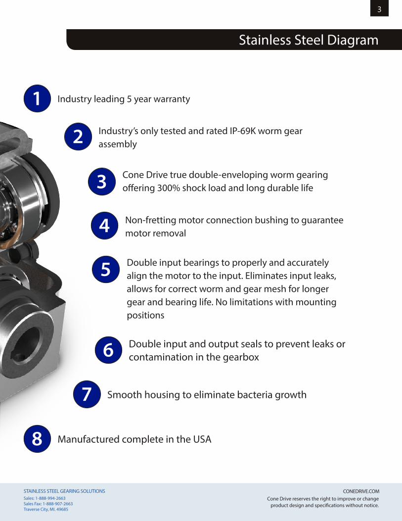
1 Industry leading 5 year warranty
2 Industry’s only tested and rated IP-69K worm gear assembly
3 Cone Drive true double-enveloping worm gearing offering 300% shock load and long durable life
4 Non-fretting motor connection bushing to guarantee motor removal
6 Double input and output seals to prevent leaks or contamination in the gearbox
7 Smooth housing to eliminate bacteria growth
5 Double input bearings to properly and accurately align the motor to the input. Eliminates input leaks, allows for correct worm and gear mesh for longer gear and bearing life. No limitations with mounting positions
8 Manufactured complete in the USA
STAINLESS STEEL GEARING SOLUTIONS CONEDRIVE.COM STAINLESS STEEL GEARING SOLUTIONS CONEDRIVE.COM Sales: 1-888-994-2663Sales Fax: 1-888-907-2663Traverse City, MI. 49685
Cone Drive reserves the right to improve or change product design and specifications without notice.
4
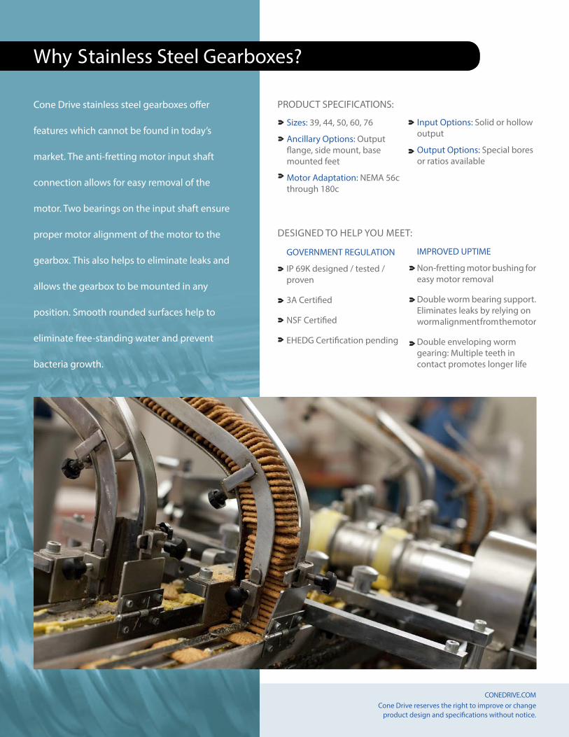
Cone Drive stainless steel gearboxes offer
features which cannot be found in today’s
market. The anti-fretting motor input shaft
connection allows for easy removal of the
motor. Two bearings on the input shaft ensure
proper motor alignment of the motor to the
gearbox. This also helps to eliminate leaks and
allows the gearbox to be mounted in any
position. Smooth rounded surfaces help to
eliminate free-standing water and prevent
bacteria growth.
Sizes: 39, 44, 50, 60, 76
Ancillary Options: Output flange, side mount, base mounted feet
Motor Adaptation: NEMA 56c through 180c
Input Options: Solid or hollow output
Output Options: Special bores or ratios available
PRODUCT SPECIFICATIONS:
GOVERNMENT REGULATION
IP 69K designed / tested / proven
3A Certified
NSF Certified
EHEDG Certification pending
IMPROVED UPTIME
Non-fretting motor bushing for easy motor removal
Double worm bearing support. Eliminates leaks by relying on worm alignment from the motor
Double enveloping worm gearing: Multiple teeth in contact promotes longer life
DESIGNED TO HELP YOU MEET:
Why Stainless Steel Gearboxes?
STAINLESS STEEL GEARING SOLUTIONS CONEDRIVE.COM STAINLESS STEEL GEARING SOLUTIONS CONEDRIVE.COM Sales: 1-888-994-2663Sales Fax: 1-888-907-2663Traverse City, MI. 49685
Cone Drive reserves the right to improve or change product design and specifications without notice.
5
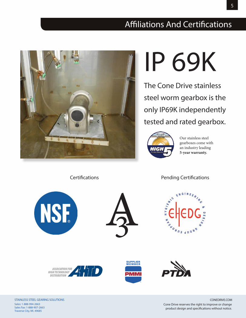
Affiliations And Certifications
IP 69K
The Cone Drive stainless
steel worm gearbox is the
only IP69K independently
tested and rated gearbox.
Certifications Pending Certifications
Our stainless steel gearboxes come with an industry leading 5-year warranty.
STAINLESS STEEL GEARING SOLUTIONS CONEDRIVE.COM STAINLESS STEEL GEARING SOLUTIONS CONEDRIVE.COM Sales: 1-888-994-2663Sales Fax: 1-888-907-2663Traverse City, MI. 49685
Cone Drive reserves the right to improve or change product design and specifications without notice.
6
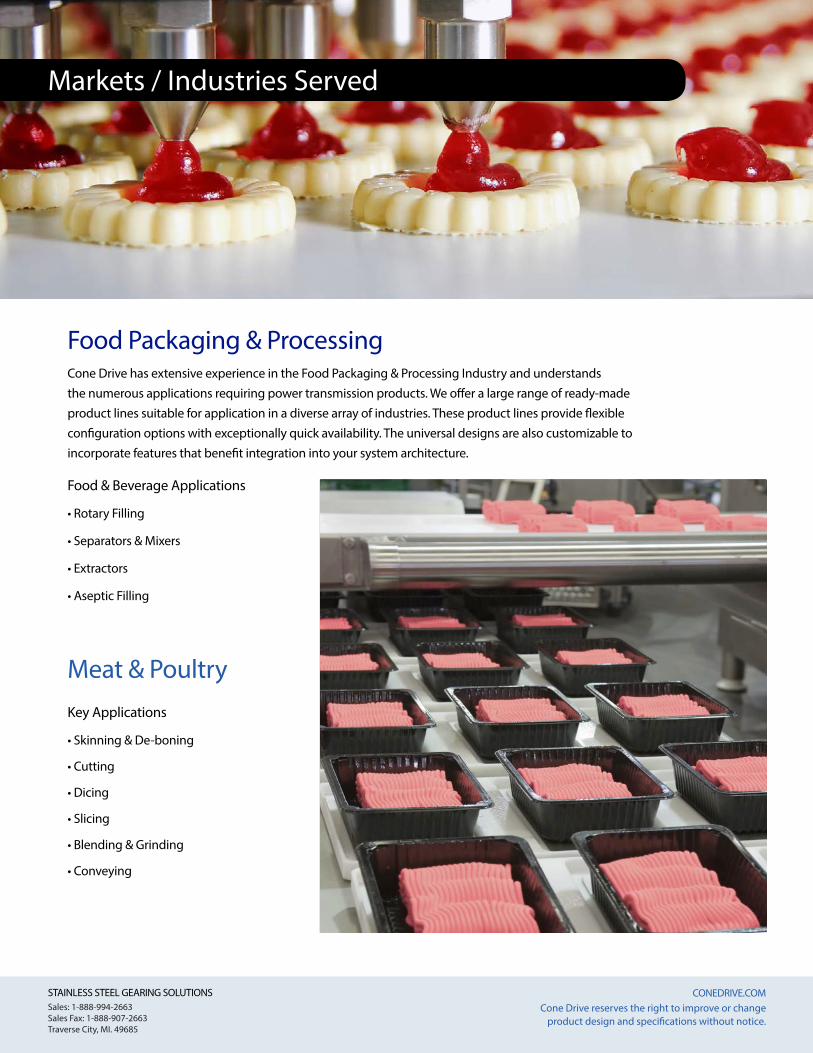
Meat & Poultry
Food Packaging & ProcessingCone Drive has extensive experience in the Food Packaging & Processing Industry and understands the numerous applications requiring power transmission products. We offer a large range of ready-made product lines suitable for application in a diverse array of industries. These product lines provide flexible configuration options with exceptionally quick availability. The universal designs are also customizable to incorporate features that benefit integration into your system architecture.
Markets / Industries Served
Food & Beverage Applications
• Rotary Filling
• Separators & Mixers
• Extractors
• Aseptic Filling
Key Applications
• Skinning & De-boning
• Cutting
• Dicing
• Slicing
• Blending & Grinding
• Conveying
STAINLESS STEEL GEARING SOLUTIONS CONEDRIVE.COM STAINLESS STEEL GEARING SOLUTIONS CONEDRIVE.COM Sales: 1-888-994-2663Sales Fax: 1-888-907-2663Traverse City, MI. 49685
Cone Drive reserves the right to improve or change product design and specifications without notice.
7
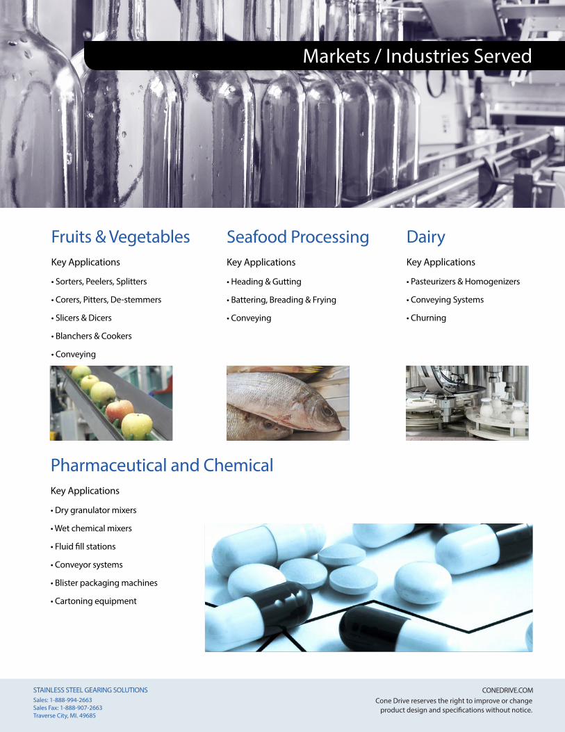
Pharmaceutical and Chemical Key Applications
• Dry granulator mixers
• Wet chemical mixers
• Fluid fill stations
• Conveyor systems
• Blister packaging machines
• Cartoning equipment
DairyKey Applications
• Pasteurizers & Homogenizers
• Conveying Systems
• Churning
Markets / Industries Served
Fruits & VegetablesKey Applications
• Sorters, Peelers, Splitters
• Corers, Pitters, De-stemmers
• Slicers & Dicers
• Blanchers & Cookers
• Conveying
Seafood ProcessingKey Applications
• Heading & Gutting
• Battering, Breading & Frying
• Conveying
STAINLESS STEEL GEARING SOLUTIONS CONEDRIVE.COM STAINLESS STEEL GEARING SOLUTIONS CONEDRIVE.COM Sales: 1-888-994-2663Sales Fax: 1-888-907-2663Traverse City, MI. 49685
Cone Drive reserves the right to improve or change product design and specifications without notice.
8
Cone Drive’s stainless steel reducers are designed for sterile manufacturing environments. The smooth housings allow for easy cleaning and bacteria free surfaces.
PACKAGING | FOOD & BEVERAGE | PHARMACEUTICAL | MEAT & DAIRY
• PROTECTION TYPE IP69K
• LIFE-TIME LUBRICATION
WITH FOOD-GRADE OIL
• DOUBLE-ENVELOPING WORM GEARING
• INCH OR METRIC SHAFTS
• DOUBLE SEAL INPUT & OUTPUT SEALS
• ASEPTIC DESIGN
• NON-FRETTING MOTOR CONNECTION
CENTER DISTANCES
NEMA FRAMES
OUTPUT TORQUE
GEAR RATIOS
OUTPUT OPTIONS
MATERIAL
1.54”, 1.75”, 1.97”, 2.38”, 3.00”
Up to 184TC frame
Up to 6,660 lb-in
From 5:1 to 60:1, single reduction
Solid or Hollow Shaft in inch or metric sizes
316 Stainless Steel
FEAT
URES
SPEC
S
T +1 888 994 2663E [email protected] www.conedrive.com
Cone Drive Operations, Inc.240 East 12th StreetTraverse City, MI 49684, USA
STAINLESS REDUCERDC
Cone DriveDC ®
Precision TechnologyMotionControl
Y5
Warranty
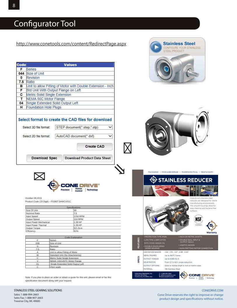
Configurator Tool
October 09,2015Product Code (15 Digit) – F03907.5AWCV01C
Note: If you plan to place an order or obtain a quote for this unit, please email or fax thisspecification document along with your request.
Cone Drive Operations, Inc.240 E. 12th Street, P.O. Box 272, Traverse City MI 49685-0272 USA Tel: 231-946-8410Tel: 231-946-8410, Sales: 888-994-2663www.conedrive.com
SpecificationsSize Of Unit 39Nominal Ratio 7.5Input Speed 1150 RPMOutput Speed 153 RPMInput Power Mechanical 1.39 HPInput Power Thermal 1.39 HPOutput Torque 521 lb-inEfficiency 91%
Code ExplanationF Series
039 Size of Unit0 Revision
7.5 RatioA Unit to allow Fitting of MotorW Standard Unit (No Attachments)C Metric Solid Single ExtensionV NEMA 143/145TC Motor Flange01 Single Extended Solid Output LeftC Viton seals
⇐
⇐ ⇘
http://www.conetools.com/content/RedirectPage.aspx
STAINLESS STEEL GEARING SOLUTIONS CONEDRIVE.COM STAINLESS STEEL GEARING SOLUTIONS CONEDRIVE.COM Sales: 1-888-994-2663Sales Fax: 1-888-907-2663Traverse City, MI. 49685
Cone Drive reserves the right to improve or change product design and specifications without notice.
9
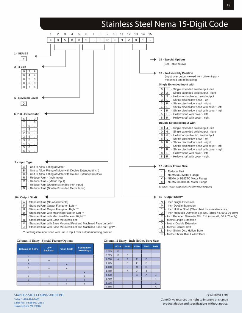
Stainless Steel Nema 15-Digit Code
Column 11 Entry - Inch Hollow Bore Sizes
F039 F044 F050 F060 F076
0.625 E0.875 F E1.000 A F E E1.125 G F F1.188 -- G G1.250 A J J1.438 A A E1.750 F1.938 G2.188 A
Column 15 Entry - Special Feature Options
Column 15 Entry Low Backlash Viton Seals Foundation
Hole Plugs
-A ●C ●F ● ●H ●J ● ●L ● ●P ● ● ●
2 - 4 Size
5 - Revision Level
6, 7, 8 - Exact Ratio
9 - Input Type
10 - Output Shaft
1 - SERIES
F
0
0 3 90 4 40 5 00 6 00 7 6
5 . 07 . 51 0 .1 5 .2 0 .2 5 .3 0 .4 0 .5 0 .6 0 .
A - Unit to Allow Fitting of MotorB - Unit to Allow Fitting of Motorwith Double Extended (inch)C - Unit to Allow Fitting of Motorwith Double Extended (metric)R - Reducer Unit - (Inch Input)M - Reducer Unit - (Metric Input)T - Reducer Unit (Double Extended Inch Input)N - Reducer Unit (Double Extended Metric Input)
Single Extended Input with:0 1 - Single extended solid output - left0 2 - Single extended solid output - right0 3 - Hollow or double ext. solid output3 L - Shrink disc hollow shaft - left3 R - Shrink disc hollow shaft - right4 L - Shrink disc hollow shaft with cover - left4 R - Shrink disc hollow shaft with cover - right5 L - Hollow shaft with cover - left5 R - Hollow shaft with cover - right
Double Extended Input with:
0 4 - Single extended solid output - left0 6 - Single extended solid output - right0 6 - Hollow or double ext. solid output6 L - Shrink disc hollow shaft - left6 R - Shrink disc hollow shaft - right7 L - Shrink disc hollow shaft with cover - left7 R - Shrink disc hollow shaft with cover - right8 L - Hollow shaft with cover - left8 R - Hollow shaft with cover - right
W - Standard Unit (No Attachments)F - Standard Unit Output Flange on Left **H - Standard Unit Output Flange on Right **D - Standard Unit with Machined Face on Left **Y - Standard Unit with Machined Face on Right **B - Standard Unit with Base Mounted FeetV - Standard Unit with Base Mounted Feet and Machined Face on Left**J - Standard Unit with Base Mounted Feet and Machined Face on Right**
** Looking into input shaft with unit in Input over output mounting position
1 2 3 4 5 6 7 8 9 10 11 12 13 14 15
F 0 5 0 0 5 . 0 R F N V 0 1 -
15 - Special Options (See Table below)
13 - 14 Assembly Position(input over output viewed from driven input - motorized end of housing)
12 - Motor Frame Size
- - Reducer UnitT - NEMA 56C Motor FlangeV - NEMA 143/145TC Motor FlangeX - NEMA 182/184TC Motor Flange
(Custom motor adaptation available upon request)
11 - Output Shaft**
N - Inch Single ExtensionP - Inch Double Extension* - Inch Hollow Shaft (*See chart for available sizesQ - Inch Reduced Diameter Sgl. Ext. (sizes 44, 50 & 76 only)R - Inch Reduced Diameter Dbl. Ext. (sizes 44, 50 & 76 only)C - Metric Single ExtensionD - Metric Double ExtensionH - Metric Hollow ShaftL - Inch Shrink Disc Hollow BoreK - Metric Shrink Disc Hollow Bore
STAINLESS STEEL GEARING SOLUTIONS CONEDRIVE.COM STAINLESS STEEL GEARING SOLUTIONS CONEDRIVE.COM Sales: 1-888-994-2663Sales Fax: 1-888-907-2663Traverse City, MI. 49685
Cone Drive reserves the right to improve or change product design and specifications without notice.
10So
lid O
utpu
t Sha
ft V
ersi
onO
utpu
t Fla
nge
Vers
ion
Foot
Mou
nt V
ersi
on
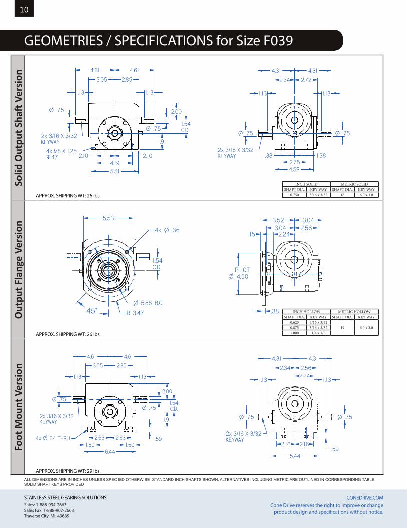
GEOMETRIES / SPECIFICATIONS for Size F039REDUCER TYPE - LESS MOUNTING FEET
APPROX. SHIPPING WT: 25.8 lbs.
1.91
1.54C.D.
.75O
.75O2x 3/16 X 3/32KEYWAY
4x M8 X 1.25.̀47
4.61
3.05 2.85
4.61
2.00
2.10 2.104.195.51
1.13 1.13
REDUCER TYPE - FLANGE MOUNT
APPROX. SHIPPING WT: 25.6 lbs.
R 3.47
O .364x
5.53
O 5.88 B.C.
1.54C.D.
45°
.15
4.50OPILOT
.38
3.523.04
3.042.56
2.24
.75O.75O
2x 3/16 X 3/32KEYWAY
4.31
2.34
4.31
1.381.382.754.59
2.72
1.13 1.13
REDUCER TYPE - FOOT MOUNT
APPROX. SHIPPING WT: 28.2 lbs.
4x O .34 THRU
.75O
.75O
.591.50 1.50
2x 3/16 X 3/32KEYWAY
3.05
4.61 4.61
2.85
2.00
1.54C.D.
1.91
6.44
2.63 2.63
1.13 1.13
.75O .75O
.59
2x 3/16 X 3/32KEYWAY
4.31 4.31
2.34 2.562.24
5.44
2.16 2.16
1.13 1.13
APPROX. SHIPPING WT: 26 lbs.
APPROX. SHIPPING WT: 29 lbs.
APPROX. SHIPPING WT: 26 lbs.
ALL DIMENSIONS ARE IN INCHES UNLESS SPEC IED OTHERWISE STANDARD INCH SHAFTS SHOWN, ALTERNATIVES INCLUDING METRIC ARE OUTLINED IN CORRESPONDING TABLE SOLID SHAFT KEYS PROVIDED
INCH HOLLOW METRIC HOLLOWSHAFT DIA. KEY WAY SHAFT DIA. KEY WAY
0.625 3/16 x 3/3219 6.0 x 3.00.875 3/16 x 3/32
1.000 1/4 x 1/8
INCH SOLID METRIC SOLIDSHAFT DIA. KEY WAY SHAFT DIA. KEY WAY
0.750 3/16 x 3/32 18 6.0 x 3.0
STAINLESS STEEL GEARING SOLUTIONS CONEDRIVE.COM STAINLESS STEEL GEARING SOLUTIONS CONEDRIVE.COM Sales: 1-888-994-2663Sales Fax: 1-888-907-2663Traverse City, MI. 49685
Cone Drive reserves the right to improve or change product design and specifications without notice.
11Ho
llow
Out
put V
ersi
onSi
de M
ount
Ver
sion
Mot
or A
dapt
er V
ersi
on
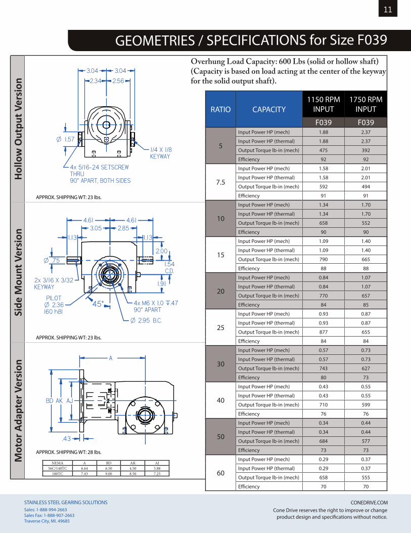
GEOMETRIES / SPECIFICATIONS for Size F039REDUCER TYPE - HOLLOW OUTPUT
APPROX. SHIPPING WT: 23.4 lbs.
1.57O
4x 5/16-24 SETSCREWTHRU90v APART, BOTH SIDES
3.04
1/4 X 1/8KEYWAY
2.56
3.04
2.34
MOTOR READY
APPROX. SHIPPING WT: 28.0 lbs.
.43
AK AJBD
A
SIDE MOUNT
APPROX. SHIPPING WT: 23.1 lbs.
.75O
2x 3/16 X 3/32KEYWAY
O 2.36PILOT
(60 h8)4x M6 X 1.0 `.4790v APART
O 2.95 B.C.
4.613.05
4.612.85
1.91
1.54C.D.
2.00
1.13 1.13
45°
APPROX. SHIPPING WT: 23 lbs.
APPROX. SHIPPING WT: 23 lbs.
APPROX. SHIPPING WT: 28 lbs.
Overhung Load Capacity: 600 Lbs (solid or hollow shaft)(Capacity is based on load acting at the center of the keyway for the solid output shaft).
NEMA A BD AK AJ56C/140TC 6.64 6.50 4.50 5.88
180TC 7.43 9.00 8.50 7.25
RATIO CAPACITY1150 RPM
INPUT1750 RPM
INPUT
F039 F039
5
Input Power HP (mech) 1.88 2.37
Input Power HP (thermal) 1.88 2.37
Output Torque lb-in (mech) 475 392
Efficiency 92 92
7.5
Input Power HP (mech) 1.58 2.01
Input Power HP (thermal) 1.58 2.01
Output Torque lb-in (mech) 592 494
Efficiency 91 91
10
Input Power HP (mech) 1.34 1.70
Input Power HP (thermal) 1.34 1.70
Output Torque lb-in (mech) 658 552
Efficiency 90 90
15
Input Power HP (mech) 1.09 1.40
Input Power HP (thermal) 1.09 1.40
Output Torque lb-in (mech) 790 665
Efficiency 88 88
20
Input Power HP (mech) 0.84 1.07
Input Power HP (thermal) 0.84 1.07
Output Torque lb-in (mech) 770 657
Efficiency 84 85
25
Input Power HP (mech) 0.93 0.87
Input Power HP (thermal) 0.93 0.87
Output Torque lb-in (mech) 877 655
Efficiency 84 84
30
Input Power HP (mech) 0.57 0.73
Input Power HP (thermal) 0.57 0.73
Output Torque lb-in (mech) 743 627
Efficiency 80 73
40
Input Power HP (mech) 0.43 0.55
Input Power HP (thermal) 0.43 0.55
Output Torque lb-in (mech) 710 599
Efficiency 76 76
50
Input Power HP (mech) 0.34 0.44
Input Power HP (thermal) 0.34 0.44
Output Torque lb-in (mech) 684 577
Efficiency 73 73
60
Input Power HP (mech) 0.29 0.37
Input Power HP (thermal) 0.29 0.37
Output Torque lb-in (mech) 658 555
Efficiency 70 70
STAINLESS STEEL GEARING SOLUTIONS CONEDRIVE.COM STAINLESS STEEL GEARING SOLUTIONS CONEDRIVE.COM Sales: 1-888-994-2663Sales Fax: 1-888-907-2663Traverse City, MI. 49685
Cone Drive reserves the right to improve or change product design and specifications without notice.
12So
lid O
utpu
t Sha
ft V
ersi
onO
utpu
t Fla
nge
Vers
ion
Foot
Mou
nt V
ersi
on
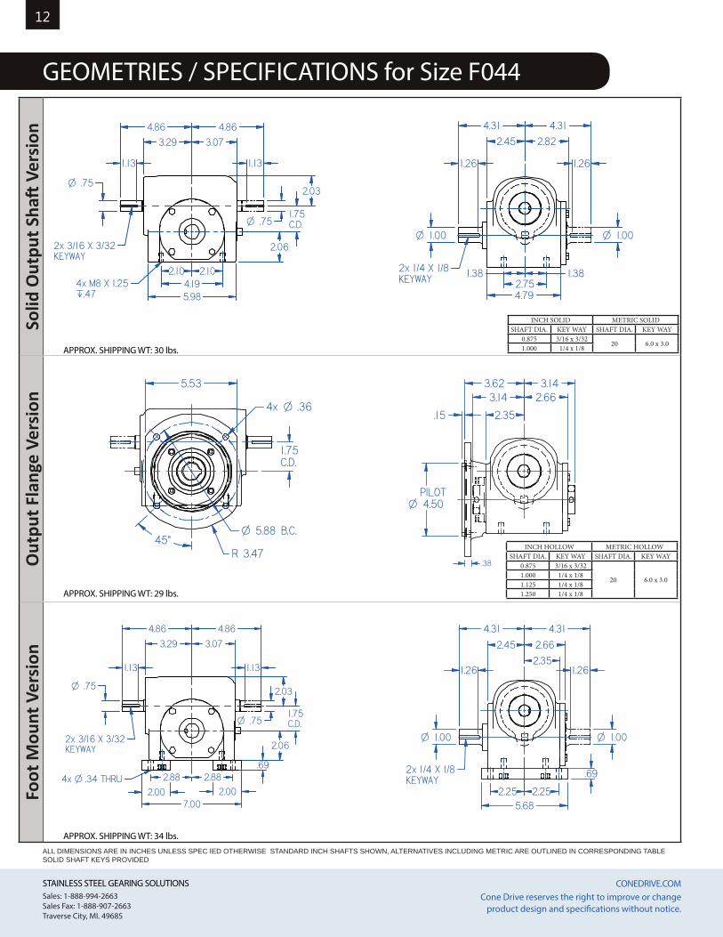
GEOMETRIES / SPECIFICATIONS for Size F044
INCH SOLID METRIC SOLIDSHAFT DIA. KEY WAY SHAFT DIA. KEY WAY
0.875 3/16 x 3/3220 6.0 x 3.0
1.000 1/4 x 1/8
INCH HOLLOW METRIC HOLLOWSHAFT DIA. KEY WAY SHAFT DIA. KEY WAY
0.875 3/16 x 3/32
20 6.0 x 3.01.000 1/4 x 1/81.125 1/4 x 1/81.250 1/4 x 1/8
REDUCER TYPE - LESS MOUNTING FEET
APPROX. SHIPPING WT: 25.8 lbs.
.75O
.75O
2x 3/16 X 3/32KEYWAY
4x M8 X 1.25.̀47
4.86
3.29
4.86
3.07
2.06
2.03
1.75C.D.
2.102.104.195.98
1.13 1.13
REDUCER TYPE - FLANGE MOUNT
APPROX. SHIPPING WT: 25.6 lbs.
5.53
1.75C.D.
O 5.88 B.C.
R 3.47
O .364x
45°
4.50OPILOT
3.143.14
2.66
2.35
3.62
.15
.38
1.00O1.00O
2x 1/4 X 1/8KEYWAY
4.31
2.45
4.31
1.38 1.382.754.79
2.82
1.26 1.26
REDUCER TYPE - FOOT MOUNT
APPROX. SHIPPING WT: 28.2 lbs.
.75O
2.002.00
.69
.75O
2x 3/16 X 3/32KEYWAY
4x O .34 THRU
3.29
4.86 4.86
3.07
2.06
1.75C.D.
2.03
2.882.88
7.00
1.13 1.13
.69
1.00O1.00O
2x 1/4 X 1/8KEYWAY
4.31
2.45 2.66
4.31
2.35
5.682.25 2.25
1.26 1.26
APPROX. SHIPPING WT: 29 lbs.
APPROX. SHIPPING WT: 34 lbs.
APPROX. SHIPPING WT: 30 lbs.
ALL DIMENSIONS ARE IN INCHES UNLESS SPEC IED OTHERWISE STANDARD INCH SHAFTS SHOWN, ALTERNATIVES INCLUDING METRIC ARE OUTLINED IN CORRESPONDING TABLE SOLID SHAFT KEYS PROVIDED
STAINLESS STEEL GEARING SOLUTIONS CONEDRIVE.COM STAINLESS STEEL GEARING SOLUTIONS CONEDRIVE.COM Sales: 1-888-994-2663Sales Fax: 1-888-907-2663Traverse City, MI. 49685
Cone Drive reserves the right to improve or change product design and specifications without notice.
13Ho
llow
Out
put V
ersi
onSi
de M
ount
Ver
sion
Mot
or A
dapt
er V
ersi
on
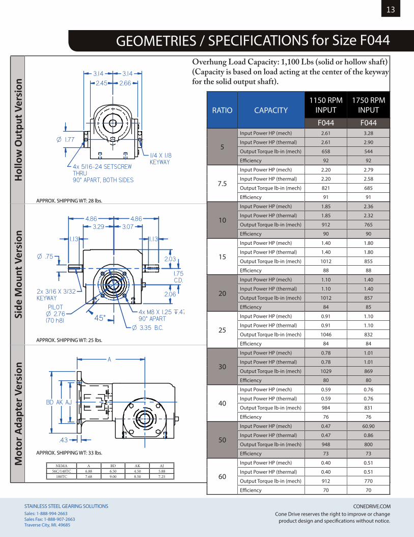
GEOMETRIES / SPECIFICATIONS for Size F044
NEMA A BD AK AJ56C/140TC 6.88 6.50 4.50 5.88
180TC 7.68 9.00 8.50 7.25
REDUCER TYPE - HOLLOW OUTPUT
APPROX. SHIPPING WT: 23.4 lbs.
1.77O
1/4 X 1/8KEYWAY
4x 5/16-24 SETSCREWTHRU90v APART, BOTH SIDES
2.45 2.66
3.14 3.14
MOTOR READY
APPROX. SHIPPING WT: 28.0 lbs.
BD
.43
AK
A
AJ
SIDE MOUNT
APPROX. SHIPPING WT: 23.1 lbs.
.75O
2x 3/16 X 3/32KEYWAY
O 2.76PILOT
(70 h8)4x M8 X 1.25 `.4790v APART
3.294.86 4.86
3.07
2.06
1.75C.D.
2.03
O 3.35 B.C.
1.13 1.13
45°
APPROX. SHIPPING WT: 28 lbs.
APPROX. SHIPPING WT: 25 lbs.
APPROX. SHIPPING WT: 33 lbs.
RATIO CAPACITY1150 RPM
INPUT1750 RPM
INPUT
F044 F044
5
Input Power HP (mech) 2.61 3.28
Input Power HP (thermal) 2.61 2.90
Output Torque lb-in (mech) 658 544
Efficiency 92 92
7.5
Input Power HP (mech) 2.20 2.79
Input Power HP (thermal) 2.20 2.58
Output Torque lb-in (mech) 821 685
Efficiency 91 91
10
Input Power HP (mech) 1.85 2.36
Input Power HP (thermal) 1.85 2.32
Output Torque lb-in (mech) 912 765
Efficiency 90 90
15
Input Power HP (mech) 1.40 1.80
Input Power HP (thermal) 1.40 1.80
Output Torque lb-in (mech) 1012 855
Efficiency 88 88
20
Input Power HP (mech) 1.10 1.40
Input Power HP (thermal) 1.10 1.40
Output Torque lb-in (mech) 1012 857
Efficiency 84 85
25
Input Power HP (mech) 0.91 1.10
Input Power HP (thermal) 0.91 1.10
Output Torque lb-in (mech) 1046 832
Efficiency 84 84
30
Input Power HP (mech) 0.78 1.01
Input Power HP (thermal) 0.78 1.01
Output Torque lb-in (mech) 1029 869
Efficiency 80 80
40
Input Power HP (mech) 0.59 0.76
Input Power HP (thermal) 0.59 0.76
Output Torque lb-in (mech) 984 831
Efficiency 76 76
50
Input Power HP (mech) 0.47 60.90
Input Power HP (thermal) 0.47 0.86
Output Torque lb-in (mech) 948 800
Efficiency 73 73
60
Input Power HP (mech) 0.40 0.51
Input Power HP (thermal) 0.40 0.51
Output Torque lb-in (mech) 912 770
Efficiency 70 70
Overhung Load Capacity: 1,100 Lbs (solid or hollow shaft)(Capacity is based on load acting at the center of the keyway for the solid output shaft).
STAINLESS STEEL GEARING SOLUTIONS CONEDRIVE.COM STAINLESS STEEL GEARING SOLUTIONS CONEDRIVE.COM Sales: 1-888-994-2663Sales Fax: 1-888-907-2663Traverse City, MI. 49685
Cone Drive reserves the right to improve or change product design and specifications without notice.
14So
lid O
utpu
t Sha
ft V
ersi
onO
utpu
t Fla
nge
Vers
ion
Foot
Mou
nt V
ersi
on
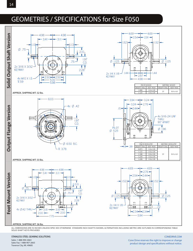
GEOMETRIES / SPECIFICATIONS for Size F050
INCH SOLID METRIC SOLIDSHAFT DIA. KEY WAY SHAFT DIA. KEY WAY
1.000 1/4 x 1/825 8.0 x 4.0
1.125 1/4 x 1/8
INCH HOLLOW METRIC HOLLOWSHAFT DIA. KEY WAY SHAFT DIA. KEY WAY
0.875 1/4 x 1/8
25 8.0 x 4.01.125 1/4 x 1/81.188 1/4 x 1/81.250 1/4 x 1/81.438 1/4 x 1/8
REDUCER TYPE - LESS MOUNTING FEET
APPROX. SHIPPING WT: 25.8 lbs.
4x M10 X 1.5.̀59
2.10.75O
.75
2x 3/16 X 3/32KEYWAY
4.98 4.983.41 3.11
2.28
1.97C.D.
2.50 2.505.005.98
1.13 1.13
REDUCER TYPE - FLANGE MOUNT
APPROX. SHIPPING WT: 25.6 lbs.R 3.78
6.03
O .424x
1.97C.D.
O 6.50 B.C.
5.25OPILOT 1.96O
4x 5/16-24 UNFTHRU90v APART
.15
.38
3.24 2.76
3.243.94
2.44
1.125O1.125O
2x 1/4 X 1/8KEYWAY
2.544.694.69
1.44 1.442.874.98
2.91
1.52 1.52
REDUCER TYPE - FOOT MOUNT
APPROX. SHIPPING WT: 28.2 lbs.
2.00 2.004x O.42 THRU
.72
.75O
.75O
2x 3/16 X 3/32KEYWAY
4.983.41
4.983.11
2.28
1.97C.D.
2.10
3.18 3.18
7.75
1.13 1.13
.72
1.125O
2x 1/4 X 1/8KEYWAY
1.125O
2.54 2.442.76
4.69 4.69
2.34 2.345.94
1.52 1.52
APPROX. SHIPPING WT: 33 lbs.
APPROX. SHIPPING WT: 32 lbs.
APPROX. SHIPPING WT: 36 lbs.ALL DIMENSIONS ARE IN INCHES UNLESS SPEC IED OTHERWISE STANDARD INCH SHAFTS SHOWN, ALTERNATIVES INCLUDING METRIC ARE OUTLINED IN CORRESPONDING TABLE SOLID SHAFT KEYS PROVIDED
STAINLESS STEEL GEARING SOLUTIONS CONEDRIVE.COM STAINLESS STEEL GEARING SOLUTIONS CONEDRIVE.COM Sales: 1-888-994-2663Sales Fax: 1-888-907-2663Traverse City, MI. 49685
Cone Drive reserves the right to improve or change product design and specifications without notice.
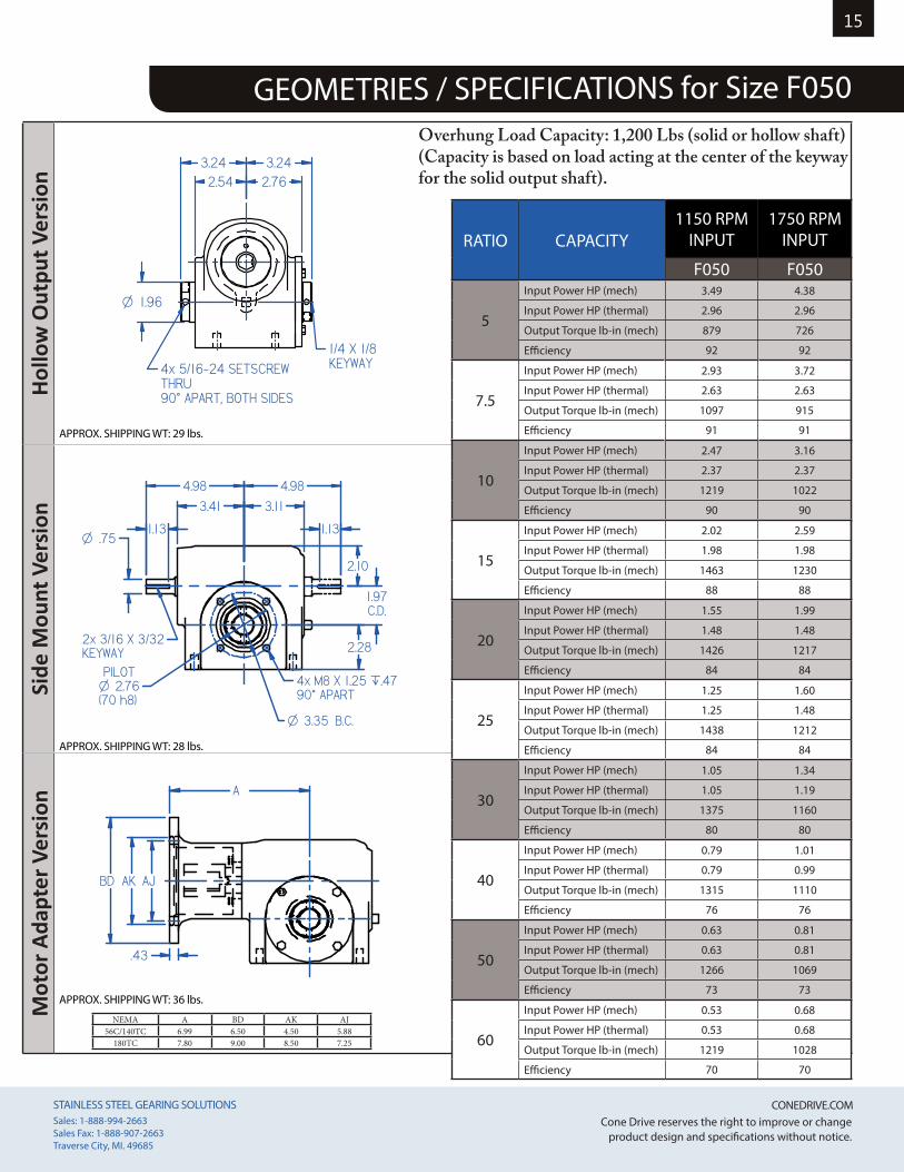
15
GEOMETRIES / SPECIFICATIONS for Size F050REDUCER TYPE - HOLLOW OUTPUT
APPROX. SHIPPING WT: 23.4 lbs.
1.96O
1/4 X 1/8KEYWAY4x 5/16-24 SETSCREW
THRU90v APART, BOTH SIDES
2.54 2.763.243.24
SIDE MOUNT
APPROX. SHIPPING WT: 23.1 lbs.
.75O
2x 3/16 X 3/32KEYWAY
O 2.76PILOT
(70 h8)4x M8 X 1.25 `.4790v APART
2.28
1.97C.D.
2.10
4.98
3.113.41
4.98
O 3.35 B.C.
1.13 1.13
MOTOR READY
APPROX. SHIPPING WT: 28.0 lbs.
BD
.43
AK
A
AJ
APPROX. SHIPPING WT: 29 lbs.
APPROX. SHIPPING WT: 28 lbs.
APPROX. SHIPPING WT: 36 lbs.
Hollo
w O
utpu
t Ver
sion
Side
Mou
nt V
ersi
onM
otor
Ada
pter
Ver
sion
RATIO CAPACITY1150 RPM
INPUT1750 RPM
INPUT
F050 F050
5
Input Power HP (mech) 3.49 4.38
Input Power HP (thermal) 2.96 2.96
Output Torque lb-in (mech) 879 726
Efficiency 92 92
7.5
Input Power HP (mech) 2.93 3.72
Input Power HP (thermal) 2.63 2.63
Output Torque lb-in (mech) 1097 915
Efficiency 91 91
10
Input Power HP (mech) 2.47 3.16
Input Power HP (thermal) 2.37 2.37
Output Torque lb-in (mech) 1219 1022
Efficiency 90 90
15
Input Power HP (mech) 2.02 2.59
Input Power HP (thermal) 1.98 1.98
Output Torque lb-in (mech) 1463 1230
Efficiency 88 88
20
Input Power HP (mech) 1.55 1.99
Input Power HP (thermal) 1.48 1.48
Output Torque lb-in (mech) 1426 1217
Efficiency 84 84
25
Input Power HP (mech) 1.25 1.60
Input Power HP (thermal) 1.25 1.48
Output Torque lb-in (mech) 1438 1212
Efficiency 84 84
30
Input Power HP (mech) 1.05 1.34
Input Power HP (thermal) 1.05 1.19
Output Torque lb-in (mech) 1375 1160
Efficiency 80 80
40
Input Power HP (mech) 0.79 1.01
Input Power HP (thermal) 0.79 0.99
Output Torque lb-in (mech) 1315 1110
Efficiency 76 76
50
Input Power HP (mech) 0.63 0.81
Input Power HP (thermal) 0.63 0.81
Output Torque lb-in (mech) 1266 1069
Efficiency 73 73
60
Input Power HP (mech) 0.53 0.68
Input Power HP (thermal) 0.53 0.68
Output Torque lb-in (mech) 1219 1028
Efficiency 70 70
Overhung Load Capacity: 1,200 Lbs (solid or hollow shaft)(Capacity is based on load acting at the center of the keyway for the solid output shaft).
NEMA A BD AK AJ56C/140TC 6.99 6.50 4.50 5.88
180TC 7.80 9.00 8.50 7.25
STAINLESS STEEL GEARING SOLUTIONS CONEDRIVE.COM STAINLESS STEEL GEARING SOLUTIONS CONEDRIVE.COM Sales: 1-888-994-2663Sales Fax: 1-888-907-2663Traverse City, MI. 49685
Cone Drive reserves the right to improve or change product design and specifications without notice.
16So
lid O
utpu
t Sha
ft V
ersi
onO
utpu
t Fla
nge
Vers
ion
Foot
Mou
nt V
ersi
on
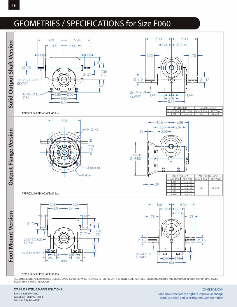
GEOMETRIES / SPECIFICATIONS for Size F060
INCH HOLLOW METRIC HOLLOWSHAFT DIA. KEY WAY SHAFT DIA. KEY WAY
1.000 1/4 x 1/8
28 8.0 x 4.01.125 1/4 x 1/81.188 1/4 x 1/81.250 1/4 x 1/81.438 1/4 x 1/8
REDUCER TYPE - LESS MOUNTING FEET
APPROX. SHIPPING WT: 25.8 lbs.
.75O
.75O
2x 3/16 X 3/32KEYWAY
4x M10 X 1.5.̀59
5.28
3.71 3.44
5.28
2.50
2.11
2.38C.D.
2.50 2.505.006.14
1.13 1.13
REDUCER TYPE - FLANGE MOUNT
APPROX. SHIPPING WT: 25.6 lbs.
O .424x
R 4.54
7.29
2.38C.D.
O 8.00 B.C
.15
6.50OPILOT
.38
2.873.363.36
2.56
4.45
2x 1/4 X 1/8KEYWAY
1.12O1.12O
5.09
2.66
5.09
1.44 1.442.875.22
3.03
1.75 1.75
REDUCER TYPE - FOOT MOUNT
APPROX. SHIPPING WT: 28.2 lbs.
2.50 2.50
4x O.42 THRU.75
.75O
2x 3/16 X 3/32KEYWAY
.75O
5.28 5.283.71 3.44
2.50
2.38C.D.
2.11
3.53 3.53
8.50
1.13 1.13
1.12O 1.12O
.752x 1/4 X 1/8KEYWAY
5.09 5.092.66 2.87
2.56
2.44 2.446.18
1.75 1.75
APPROX. SHIPPING WT: 41 lbs.
APPROX. SHIPPING WT: 40 lbs.
APPROX. SHIPPING WT: 46 lbs.
ALL DIMENSIONS ARE IN INCHES UNLESS SPEC IED OTHERWISE STANDARD INCH SHAFTS SHOWN, ALTERNATIVES INCLUDING METRIC ARE OUTLINED IN CORRESPONDING TABLE SOLID SHAFT KEYS PROVIDED
INCH SOLID METRIC SOLIDSHAFT DIA. KEY WAY SHAFT DIA. KEY WAY
1.125 1/4 x 1/8 28 8.0 x 4.0
STAINLESS STEEL GEARING SOLUTIONS CONEDRIVE.COM STAINLESS STEEL GEARING SOLUTIONS CONEDRIVE.COM Sales: 1-888-994-2663Sales Fax: 1-888-907-2663Traverse City, MI. 49685
Cone Drive reserves the right to improve or change product design and specifications without notice.
17
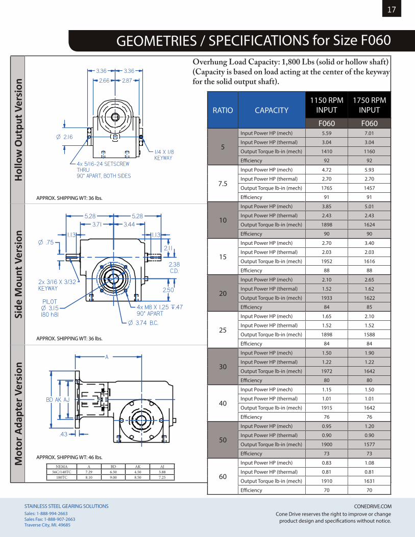
GEOMETRIES / SPECIFICATIONS for Size F060
Hollo
w O
utpu
t Ver
sion
Side
Mou
nt V
ersi
onM
otor
Ada
pter
Ver
sion
REDUCER TYPE - HOLLOW OUTPUT
APPROX. SHIPPING WT: 23.4 lbs.
2.16O
1/4 X 1/8KEYWAY
4x 5/16-24 SETSCREWTHRU90v APART, BOTH SIDES
3.36 3.36
2.66 2.87
SIDE MOUNT
APPROX. SHIPPING WT: 23.1 lbs.
.75O
O 3.15PILOT
(80 h8)4x M8 X 1.25 `.4790v APART
2x 3/16 X 3/32KEYWAY
5.283.71
5.283.44
2.11
2.38C.D.
2.50
O 3.74 B.C.
1.13 1.13
APPROX. SHIPPING WT: 36 lbs.
APPROX. SHIPPING WT: 36 lbs.
APPROX. SHIPPING WT: 46 lbs.
Overhung Load Capacity: 1,800 Lbs (solid or hollow shaft)(Capacity is based on load acting at the center of the keyway for the solid output shaft).
MOTOR READY
APPROX. SHIPPING WT: 28.0 lbs.
.43
AK AJBD
A
NEMA A BD AK AJ56C/140TC 7.29 6.50 4.50 5.88
180TC 8.10 9.00 8.50 7.25
RATIO CAPACITY1150 RPM
INPUT1750 RPM
INPUT
F060 F060
5
Input Power HP (mech) 5.59 7.01
Input Power HP (thermal) 3.04 3.04
Output Torque lb-in (mech) 1410 1160
Efficiency 92 92
7.5
Input Power HP (mech) 4.72 5.93
Input Power HP (thermal) 2.70 2.70
Output Torque lb-in (mech) 1765 1457
Efficiency 91 91
10
Input Power HP (mech) 3.85 5.01
Input Power HP (thermal) 2.43 2.43
Output Torque lb-in (mech) 1898 1624
Efficiency 90 90
15
Input Power HP (mech) 2.70 3.40
Input Power HP (thermal) 2.03 2.03
Output Torque lb-in (mech) 1952 1616
Efficiency 88 88
20
Input Power HP (mech) 2.10 2.65
Input Power HP (thermal) 1.52 1.62
Output Torque lb-in (mech) 1933 1622
Efficiency 84 85
25
Input Power HP (mech) 1.65 2.10
Input Power HP (thermal) 1.52 1.52
Output Torque lb-in (mech) 1898 1588
Efficiency 84 84
30
Input Power HP (mech) 1.50 1.90
Input Power HP (thermal) 1.22 1.22
Output Torque lb-in (mech) 1972 1642
Efficiency 80 80
40
Input Power HP (mech) 1.15 1.50
Input Power HP (thermal) 1.01 1.01
Output Torque lb-in (mech) 1915 1642
Efficiency 76 76
50
Input Power HP (mech) 0.95 1.20
Input Power HP (thermal) 0.90 0.90
Output Torque lb-in (mech) 1900 1577
Efficiency 73 73
60
Input Power HP (mech) 0.83 1.08
Input Power HP (thermal) 0.81 0.81
Output Torque lb-in (mech) 1910 1631
Efficiency 70 70
STAINLESS STEEL GEARING SOLUTIONS CONEDRIVE.COM STAINLESS STEEL GEARING SOLUTIONS CONEDRIVE.COM Sales: 1-888-994-2663Sales Fax: 1-888-907-2663Traverse City, MI. 49685
Cone Drive reserves the right to improve or change product design and specifications without notice.
18So
lid O
utpu
t Sha
ft V
ersi
onO
utpu
t Fla
nge
Vers
ion
Foot
Mou
nt V
ersi
on
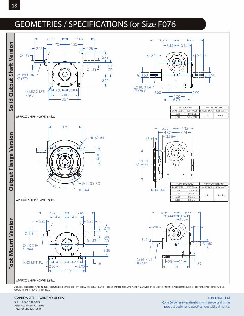
GEOMETRIES / SPECIFICATIONS for Size F076REDUCER TYPE - LESS MOUNTING FEET
APPROX. SHIPPING WT: 87.4 lbs.
4.70 4.55
7.77 7.48
3.25
3.00C.D.
2.79
2.25
1.19O
8.277.00
3.50 3.50
1.19O
2.25
4x M12 X 1.75`19.5
2x 1/8 X 1/4KEYWAY
REDUCER TYPE - FLANGE MOUNT
APPROX. SHIPPING WT: 25.6 lbs.
3.00C.D.
O .544x
8.79
R 5.64
O 10.00 B.C45°
4.323.74
3.354.32
5.50
.15
8.00OPILOT
.44
6.75
3.44
6.75
3.74
1.50O
2x 1/8 X 1/4KEYWAY
6.794.00
2.00 2.00
1.50O
2.01 2.01
7.77 7.484.554.70
2.25 2.25
10.002.00 2.00
.75
3.25
4.22 4.22
3.00C.D.1.19O
1.19O
2.79
2x 1/8 X 1/4KEYWAY
4x O13.5 THRU7.50
2.94 2.94 .75
3.443.353.74
2.012.01
6.75 6.75
1.50O1.50
2x 1/8 X 1/4KEYWAY
APPROX. SHIPPING WT: 89 lbs.
APPROX. SHIPPING WT: 87 lbs.
APPROX. SHIPPING WT: 82 lbs.
ALL DIMENSIONS ARE IN INCHES UNLESS SPEC IED OTHERWISE STANDARD INCH SHAFTS SHOWN, ALTERNATIVES INCLUDING METRIC ARE OUTLINED IN CORRESPONDING TABLE SOLID SHAFT KEYS PROVIDED
INCH SOLID METRIC SOLIDSHAFT DIA. KEY WAY SHAFT DIA. KEY WAY
1.250 1/4 x 1/835 10 x 4.4
1.500 3/8 x 3/16
INCH HOLLOW METRIC HOLLOWSHAFT DIA. KEY WAY SHAFT DIA. KEY WAY
1.438 3/8 x 3/16
35 10 x 4.41.750 3/8 x 3/161.938 1/2 x 1/42.188 1/2 x 1/4
STAINLESS STEEL GEARING SOLUTIONS CONEDRIVE.COM STAINLESS STEEL GEARING SOLUTIONS CONEDRIVE.COM Sales: 1-888-994-2663Sales Fax: 1-888-907-2663Traverse City, MI. 49685
Cone Drive reserves the right to improve or change product design and specifications without notice.
19
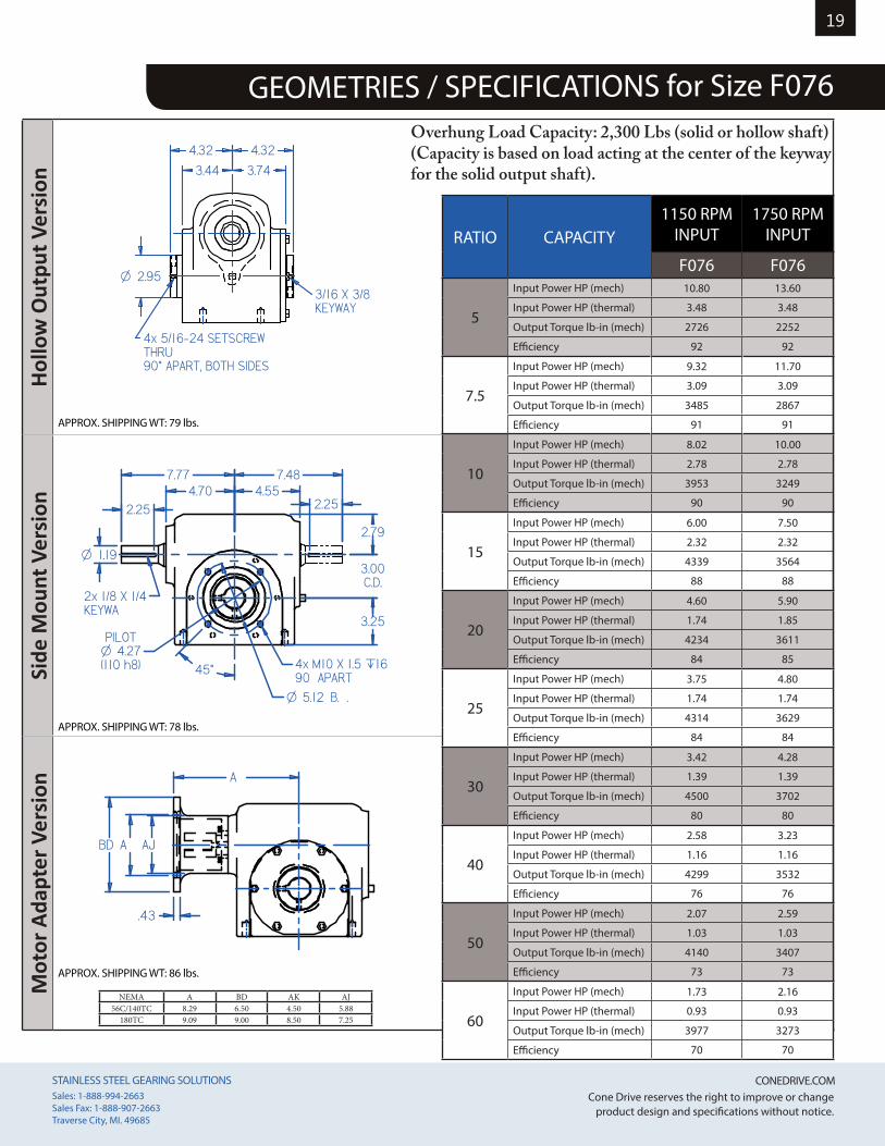
GEOMETRIES / SPECIFICATIONS for Size F076
Hollo
w O
utpu
t Ver
sion
Side
Mou
nt V
ersi
onM
otor
Ada
pter
Ver
sion
REDUCER TYPE - HOLLOW OUTPUT
APPROX. SHIPPING WT: 23.4 lbs.
4.32 4.32
3.44 3.74
2.95O3/16 X 3/8KEYWAY
4x 5/16-24 SETSCREWTHRU90v APART, BOTH SIDES
MOTOR READY
APPROX. SHIPPING WT: 28.0 lbs.
BD A AJ
A
.43
SIDE MOUNT
APPROX. SHIPPING WT: 23.1 lbs.
4.707.77
4.557.48
2.25 2.25
3.25
3.00C.D.
2.79
1.19O
O 4.27PILOT
(110 h8)
O 5.12 B. .
4x M10 X 1.5 `1690 APART
2x 1/8 X 1/4KEYWA
45°
APPROX. SHIPPING WT: 79 lbs.
APPROX. SHIPPING WT: 78 lbs.
APPROX. SHIPPING WT: 86 lbs.
RATIO CAPACITY1150 RPM
INPUT1750 RPM
INPUT
F076 F076
5
Input Power HP (mech) 10.80 13.60
Input Power HP (thermal) 3.48 3.48
Output Torque lb-in (mech) 2726 2252
Efficiency 92 92
7.5
Input Power HP (mech) 9.32 11.70
Input Power HP (thermal) 3.09 3.09
Output Torque lb-in (mech) 3485 2867
Efficiency 91 91
10
Input Power HP (mech) 8.02 10.00
Input Power HP (thermal) 2.78 2.78
Output Torque lb-in (mech) 3953 3249
Efficiency 90 90
15
Input Power HP (mech) 6.00 7.50
Input Power HP (thermal) 2.32 2.32
Output Torque lb-in (mech) 4339 3564
Efficiency 88 88
20
Input Power HP (mech) 4.60 5.90
Input Power HP (thermal) 1.74 1.85
Output Torque lb-in (mech) 4234 3611
Efficiency 84 85
25
Input Power HP (mech) 3.75 4.80
Input Power HP (thermal) 1.74 1.74
Output Torque lb-in (mech) 4314 3629
Efficiency 84 84
30
Input Power HP (mech) 3.42 4.28
Input Power HP (thermal) 1.39 1.39
Output Torque lb-in (mech) 4500 3702
Efficiency 80 80
40
Input Power HP (mech) 2.58 3.23
Input Power HP (thermal) 1.16 1.16
Output Torque lb-in (mech) 4299 3532
Efficiency 76 76
50
Input Power HP (mech) 2.07 2.59
Input Power HP (thermal) 1.03 1.03
Output Torque lb-in (mech) 4140 3407
Efficiency 73 73
60
Input Power HP (mech) 1.73 2.16
Input Power HP (thermal) 0.93 0.93
Output Torque lb-in (mech) 3977 3273
Efficiency 70 70
Overhung Load Capacity: 2,300 Lbs (solid or hollow shaft)(Capacity is based on load acting at the center of the keyway for the solid output shaft).
NEMA A BD AK AJ56C/140TC 8.29 6.50 4.50 5.88
180TC 9.09 9.00 8.50 7.25
STAINLESS STEEL GEARING SOLUTIONS CONEDRIVE.COM STAINLESS STEEL GEARING SOLUTIONS CONEDRIVE.COM Sales: 1-888-994-2663Sales Fax: 1-888-907-2663Traverse City, MI. 49685
Cone Drive reserves the right to improve or change product design and specifications without notice.
20
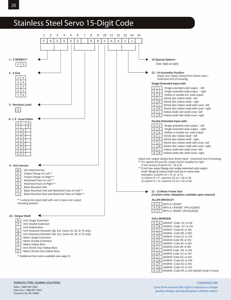
Stainless Steel Servo 15-Digit Code
15 Special Options
13 - 14 Assembly Position
Single Extended Input with:
Double Extended Input with:
3 - 4 Size
5 - Revision Level
6, 7, 8 - Exact Ratio
9 - Unit Version
10 - Output Shaft
1 - 2 SERIES F
F S
0
3 94 45 06 07 6
5 . 07 . 51 0 .1 5 .2 0 .2 5 .3 0 .4 0 .5 0 .6 0 .
W - (No Attachments)F - Output Flange on Left **H - Output Flange on Right **D - Machined Face on Left **Y - Machined Face on Right **B - Base Mounted FeetV - Base Mounted Feet and Machined Face on Left **J - Base Mounted Feet and Machined Face on Right **
** Looking into input shaft with unit in input over output mounting position
0 1 - Single extended solid output - left0 2 - Single extended solid output - right0 3 - Hollow or double ext. solid output3 L - Shrink disc hollow shaft - left3 R - Shrink disc hollow shaft - right4 L - Shrink disc hollow shaft with cover -left4 R - Shrink disc hollow shaft with cover -right5 L - Hollow shaft with shaft cover -left5 R - Hollow shaft with shaft cover -right
0 4 - Single extended solid output - left0 5 - Single extended solid output - right0 6 - Hollow or double ext. solid output6 L - Shrink disc hollow shaft - left6 R - Shrink disc hollow shaft - right7 L - Shrink disc hollow shaft with cover -left7 R - Shrink disc hollow shaft with cover -right8 L - Hollow shaft with shaft cover -left8 R - Hollow shaft with shaft cover -right
N - Inch Single ExtensionP - Inch Double Extension* - Inch Hollow BoreQ - Inch Reduced Diameter Sgl. Ext. (sizes 44, 50, & 76 only)R - Inch Reduced Diameter Dbl. Ext. (sizes 44, 50, & 76 only)C - Metric Single ExtensionD - Metric Double ExtensionH - Metric Hollow BoreL - Inch Shrink Disc Hollow BoreK - Metric Shrink Disc Hollow Bore
** Additional bore sizes available see page 21
11 - 12 Motor Frame Size (Custom motor adaptation available upon request)
ALLEN BRADLEYA A MPS-A / B330P A B MPS-A / B4540F, VPS-A1304DA C MPS-A / B560F, VPS-B1653D
KOLLMORGENK A AKMH3 Code AC or AN K B AKMH3 Code CC or CNK C AKMH4 Code AC or ANK D AKMH4 Code BK or BNK E AKMH4 Code CC or CNK F AKMH4 Code DK or DNK H AKMH5 Code AC or ANK I AKMH5 Code BK or BN K J AKMH5 Code DK or DNK K AKMH5 Code CC or CNK L AKMH5 Code GC or GNK M AKMH5 Code HC or HNK P AKMH6 Code AC or ANK Q AKMH6 Code CC or CNK R AKMH6, Code DK or DN (NEMA Small C-Face)
1 2 3 4 5 6 7 8 9 10 11 12 13 14 15
F S 5 0 0 5 . 0 R F A A 1 1
(See Table at right)
(input over output viewed from driven input - motorized end of housing)
(input over output viewed from driven input - motorized end of housing)** For options 03 and 06, output carrier installed on right if unit version (Column 9) = W or B** If unit has output flange and single extended solid output shaft, flange & output shaft must be on same side. examples: (column 10 = N, Q, or C) 1) column 9 = F; columns 13-14 = 01 or 04 2) column 9 = H; columns 13-14 = 02 or 05
STAINLESS STEEL GEARING SOLUTIONS CONEDRIVE.COM STAINLESS STEEL GEARING SOLUTIONS CONEDRIVE.COM Sales: 1-888-994-2663Sales Fax: 1-888-907-2663Traverse City, MI. 49685
Cone Drive reserves the right to improve or change product design and specifications without notice.
21
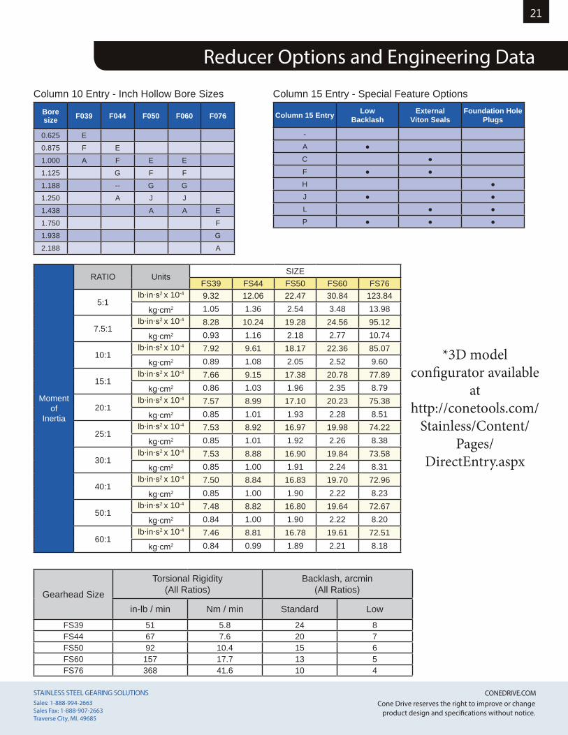
Reducer Options and Engineering Data
Column 15 Entry - Special Feature Options
Column 15 Entry Low Backlash
External Viton Seals
Foundation Hole Plugs
-A ●C ●F ● ●H ●J ● ●L ● ●P ● ● ●
Column 10 Entry - Inch Hollow Bore SizesBore size F039 F044 F050 F060 F076
0.625 E0.875 F E1.000 A F E E1.125 G F F1.188 -- G G1.250 A J J1.438 A A E1.750 F1.938 G2.188 A
Gearhead Size
Torsional Rigidity (All Ratios)
Backlash, arcmin(All Ratios)
in-lb / min Nm / min Standard LowFS39 51 5.8 24 8FS44 67 7.6 20 7FS50 92 10.4 15 6FS60 157 17.7 13 5FS76 368 41.6 10 4
*3D model configurator available
at http://conetools.com/
Stainless/Content/Pages/
DirectEntry.aspx
Moment of
Inertia
RATIO Units SIZEFS39 FS44 FS50 FS60 FS76
5:1lb∙in∙s2 x 10-4 9.32 12.06 22.47 30.84 123.84
kg∙cm2 1.05 1.36 2.54 3.48 13.98
7.5:1lb∙in∙s2 x 10-4 8.28 10.24 19.28 24.56 95.12
kg∙cm2 0.93 1.16 2.18 2.77 10.74
10:1lb∙in∙s2 x 10-4 7.92 9.61 18.17 22.36 85.07
kg∙cm2 0.89 1.08 2.05 2.52 9.60
15:1lb∙in∙s2 x 10-4 7.66 9.15 17.38 20.78 77.89
kg∙cm2 0.86 1.03 1.96 2.35 8.79
20:1lb∙in∙s2 x 10-4 7.57 8.99 17.10 20.23 75.38
kg∙cm2 0.85 1.01 1.93 2.28 8.51
25:1lb∙in∙s2 x 10-4 7.53 8.92 16.97 19.98 74.22
kg∙cm2 0.85 1.01 1.92 2.26 8.38
30:1lb∙in∙s2 x 10-4 7.53 8.88 16.90 19.84 73.58
kg∙cm2 0.85 1.00 1.91 2.24 8.31
40:1lb∙in∙s2 x 10-4 7.50 8.84 16.83 19.70 72.96
kg∙cm2 0.85 1.00 1.90 2.22 8.23
50:1lb∙in∙s2 x 10-4 7.48 8.82 16.80 19.64 72.67
kg∙cm2 0.84 1.00 1.90 2.22 8.20
60:1lb∙in∙s2 x 10-4 7.46 8.81 16.78 19.61 72.51
kg∙cm2 0.84 0.99 1.89 2.21 8.18
STAINLESS STEEL GEARING SOLUTIONS CONEDRIVE.COM STAINLESS STEEL GEARING SOLUTIONS CONEDRIVE.COM Sales: 1-888-994-2663Sales Fax: 1-888-907-2663Traverse City, MI. 49685
Cone Drive reserves the right to improve or change product design and specifications without notice.
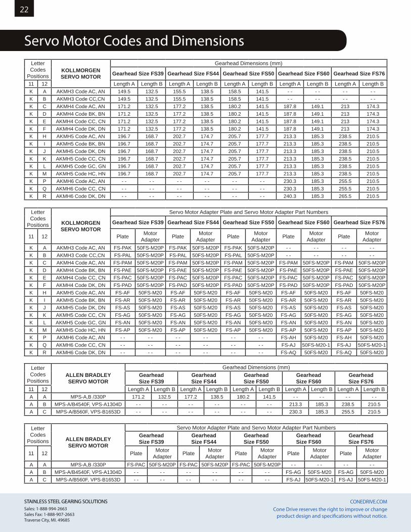
22
Servo Motor Codes and DimensionsLetter Codes
PositionsKOLLMORGEN SERVO MOTOR
Gearhead Dimensions (mm)
Gearhead Size FS39 Gearhead Size FS44 Gearhead Size FS50 Gearhead Size FS60 Gearhead Size FS76
11 12 Length A Length B Length A Length B Length A Length B Length A Length B Length A Length BK A AKMH3 Code AC, AN 149.5 132.5 155.5 138.5 158.5 141.5 - - - - - - - -K B AKMH3 Code CC,CN 149.5 132.5 155.5 138.5 158.5 141.5 - - - - - - - -K C AKMH4 Code AC, AN 171.2 132.5 177.2 138.5 180.2 141.5 187.8 149.1 213 174.3K D AKMH4 Code BK, BN 171.2 132.5 177.2 138.5 180.2 141.5 187.8 149.1 213 174.3K E AKMH4 Code CC, CN 171.2 132.5 177.2 138.5 180.2 141.5 187.8 149.1 213 174.3K F AKMH4 Code DK, DN 171.2 132.5 177.2 138.5 180.2 141.5 187.8 149.1 213 174.3K H AKMH5 Code AC, AN 196.7 168.7 202.7 174.7 205.7 177.7 213.3 185.3 238.5 210.5K I AKMH5 Code BK, BN 196.7 168.7 202.7 174.7 205.7 177.7 213.3 185.3 238.5 210.5K J AKMH5 Code DK, DN 196.7 168.7 202.7 174.7 205.7 177.7 213.3 185.3 238.5 210.5K K AKMH5 Code CC, CN 196.7 168.7 202.7 174.7 205.7 177.7 213.3 185.3 238.5 210.5K L AKMH5 Code GC, GN 196.7 168.7 202.7 174.7 205.7 177.7 213.3 185.3 238.5 210.5K M AKMH5 Code HC, HN 196.7 168.7 202.7 174.7 205.7 177.7 213.3 185.3 238.5 210.5K P AKMH6 Code AC, AN - - - - - - - - - - - - 230.3 185.3 255.5 210.5K Q AKMH6 Code CC, CN - - - - - - - - - - - - 230.3 185.3 255.5 210.5K R AKMH6 Code DK, DN - - - - - - - - - - - - 240.3 185.3 265.5 210.5
Letter Codes
Positions KOLLMORGEN SERVO MOTOR
Servo Motor Adapter Plate and Servo Motor Adapter Part Numbers
Gearhead Size FS39 Gearhead Size FS44 Gearhead Size FS50 Gearhead Size FS60 Gearhead Size FS76
11 12 Plate Motor Adapter Plate Motor
Adapter Plate Motor Adapter Plate Motor
Adapter Plate Motor Adapter
K A AKMH3 Code AC, AN FS-PAK 50FS-M20P FS-PAK 50FS-M20P FS-PAK 50FS-M20P - - - - - - - -K B AKMH3 Code CC,CN FS-PAL 50FS-M20P FS-PAL 50FS-M20P FS-PAL 50FS-M20P - - - - - - - -K C AKMH4 Code AC, AN FS-PAM 50FS-M20P FS-PAM 50FS-M20P FS-PAM 50FS-M20P FS-PAM 50FS-M20P FS-PAM 50FS-M20PK D AKMH4 Code BK, BN FS-PAE 50FS-M20P FS-PAE 50FS-M20P FS-PAE 50FS-M20P FS-PAE 50FS-M20P FS-PAE 50FS-M20PK E AKMH4 Code CC, CN FS-PAC 50FS-M20P FS-PAC 50FS-M20P FS-PAC 50FS-M20P FS-PAC 50FS-M20P FS-PAC 50FS-M20PK F AKMH4 Code DK, DN FS-PAD 50FS-M20P FS-PAD 50FS-M20P FS-PAD 50FS-M20P FS-PAD 50FS-M20P FS-PAD 50FS-M20PK H AKMH5 Code AC, AN FS-AF 50FS-M20 FS-AF 50FS-M20 FS-AF 50FS-M20 FS-AF 50FS-M20 FS-AF 50FS-M20K I AKMH5 Code BK, BN FS-AR 50FS-M20 FS-AR 50FS-M20 FS-AR 50FS-M20 FS-AR 50FS-M20 FS-AR 50FS-M20K J AKMH5 Code DK, DN FS-AS 50FS-M20 FS-AS 50FS-M20 FS-AS 50FS-M20 FS-AS 50FS-M20 FS-AS 50FS-M20K K AKMH5 Code CC, CN FS-AG 50FS-M20 FS-AG 50FS-M20 FS-AG 50FS-M20 FS-AG 50FS-M20 FS-AG 50FS-M20K L AKMH5 Code GC, GN FS-AN 50FS-M20 FS-AN 50FS-M20 FS-AN 50FS-M20 FS-AN 50FS-M20 FS-AN 50FS-M20K M AKMH5 Code HC, HN FS-AP 50FS-M20 FS-AP 50FS-M20 FS-AP 50FS-M20 FS-AP 50FS-M20 FS-AP 50FS-M20K P AKMH6 Code AC, AN - - - - - - - - - - - - FS-AH 50FS-M20 FS-AH 50FS-M20K Q AKMH6 Code CC, CN - - - - - - - - - - - - FS-AJ 50FS-M20-1 FS-AJ 50FS-M20-1K R AKMH6 Code DK, DN - - - - - - - - - - - - FS-AQ 50FS-M20 FS-AQ 50FS-M20
Letter Codes
PositionsALLEN BRADLEY SERVO MOTOR
Gearhead Dimensions (mm)Gearhead Size FS39
Gearhead Size FS44
Gearhead Size FS50
Gearhead Size FS60
Gearhead Size FS76
11 12 Length A Length B Length A Length B Length A Length B Length A Length B Length A Length BA A MPS-A,B /330P 171.2 132.5 177.2 138.5 180.2 141.5 - - - - - - - -A B MPS-A/B4540F, VPS-A1304D - - - - - - - - - - - - 213.3 185.3 238.5 210.5A C MPS-A/B560F, VPS-B1653D - - - - - - - - - - - - 230.3 185.3 255.5 210.5
Letter Codes
Positions ALLEN BRADLEY SERVO MOTOR
Servo Motor Adapter Plate and Servo Motor Adapter Part NumbersGearhead Size FS39
Gearhead Size FS44
Gearhead Size FS50
Gearhead Size FS60
Gearhead Size FS76
11 12 Plate Motor Adapter Plate Motor
Adapter Plate Motor Adapter Plate Motor
Adapter Plate Motor Adapter
A A MPS-A,B /330P FS-PAC 50FS-M20P FS-PAC 50FS-M20P FS-PAC 50FS-M20P - - - - - - - -A B MPS-A/B4540F, VPS-A1304D - - - - - - - - - - - - FS-AG 50FS-M20 FS-AG 50FS-M20A C MPS-A/B560F, VPS-B1653D - - - - - - - - - - - - FS-AJ 50FS-M20-1 FS-AJ 50FS-M20-1
STAINLESS STEEL GEARING SOLUTIONS CONEDRIVE.COM STAINLESS STEEL GEARING SOLUTIONS CONEDRIVE.COM Sales: 1-888-994-2663Sales Fax: 1-888-907-2663Traverse City, MI. 49685
Cone Drive reserves the right to improve or change product design and specifications without notice.
23
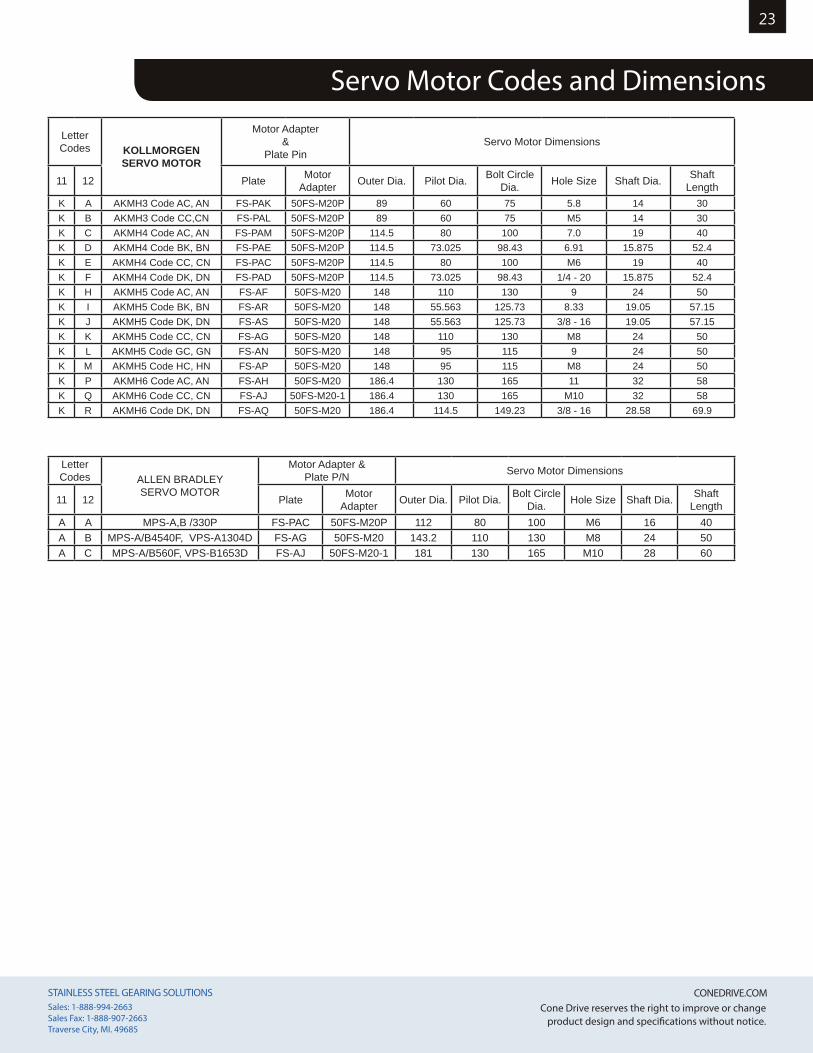
Servo Motor Codes and Dimensions
Letter Codes KOLLMORGEN
SERVO MOTOR
Motor Adapter &
Plate PinServo Motor Dimensions
11 12 Plate Motor Adapter Outer Dia. Pilot Dia. Bolt Circle
Dia. Hole Size Shaft Dia. Shaft Length
K A AKMH3 Code AC, AN FS-PAK 50FS-M20P 89 60 75 5.8 14 30K B AKMH3 Code CC,CN FS-PAL 50FS-M20P 89 60 75 M5 14 30K C AKMH4 Code AC, AN FS-PAM 50FS-M20P 114.5 80 100 7.0 19 40K D AKMH4 Code BK, BN FS-PAE 50FS-M20P 114.5 73.025 98.43 6.91 15.875 52.4K E AKMH4 Code CC, CN FS-PAC 50FS-M20P 114.5 80 100 M6 19 40K F AKMH4 Code DK, DN FS-PAD 50FS-M20P 114.5 73.025 98.43 1/4 - 20 15.875 52.4K H AKMH5 Code AC, AN FS-AF 50FS-M20 148 110 130 9 24 50K I AKMH5 Code BK, BN FS-AR 50FS-M20 148 55.563 125.73 8.33 19.05 57.15K J AKMH5 Code DK, DN FS-AS 50FS-M20 148 55.563 125.73 3/8 - 16 19.05 57.15K K AKMH5 Code CC, CN FS-AG 50FS-M20 148 110 130 M8 24 50K L AKMH5 Code GC, GN FS-AN 50FS-M20 148 95 115 9 24 50K M AKMH5 Code HC, HN FS-AP 50FS-M20 148 95 115 M8 24 50K P AKMH6 Code AC, AN FS-AH 50FS-M20 186.4 130 165 11 32 58K Q AKMH6 Code CC, CN FS-AJ 50FS-M20-1 186.4 130 165 M10 32 58K R AKMH6 Code DK, DN FS-AQ 50FS-M20 186.4 114.5 149.23 3/8 - 16 28.58 69.9
Letter Codes ALLEN BRADLEY
SERVO MOTOR
Motor Adapter & Plate P/N Servo Motor Dimensions
11 12 Plate Motor Adapter Outer Dia. Pilot Dia. Bolt Circle
Dia. Hole Size Shaft Dia. Shaft Length
A A MPS-A,B /330P FS-PAC 50FS-M20P 112 80 100 M6 16 40A B MPS-A/B4540F, VPS-A1304D FS-AG 50FS-M20 143.2 110 130 M8 24 50A C MPS-A/B560F, VPS-B1653D FS-AJ 50FS-M20-1 181 130 165 M10 28 60
STAINLESS STEEL GEARING SOLUTIONS CONEDRIVE.COM STAINLESS STEEL GEARING SOLUTIONS CONEDRIVE.COM Sales: 1-888-994-2663Sales Fax: 1-888-907-2663Traverse City, MI. 49685
Cone Drive reserves the right to improve or change product design and specifications without notice.
24
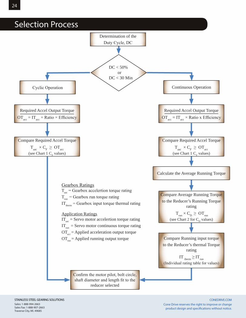
Selection Process
Continuous Operation
Calculate the Average Running Torque
Required Accel Output TorqueOTacc = ITacc × Ratio x Efficiency
Required Accel Output TorqueOTacc = ITacc × Ratio × Efficiency
Compare Required Accel TorqueTaac × CF ≥ OTacc
(see Chart 1 CF values)
Compare Required Accel TorqueTaac × CF ≥ OTacc
(see Chart 1 CF values)
Confirm the motor pilot, bolt circle, shaft diameter and length fit to the
reducer selected
Compare Running input torqueto the Reducer’s thermal Torque
ratingIT therm ≥ ITrun
(Individual rating table for values)
Cyclic Operation
Gearbox RatingsTaac = Gearbox accelertion torque ratingTrun = Gearbox run torque ratingITtherm = Gearbox input torque thermal rating
Application RatingsITaac = Servo motor accelertion torque ratingITrun = Servo motor continuous torque ratingOTacc = Applied acceleration output torqueOTrun = Applied running output torque
DC < 50%
or DC < 30 Min
Determination of the Duty Cycle, DC
Compare Average Running Torqueto the Reducer’s Running Torque
rating Trun × CD ≥ OTrun
(see Chart 2 for CD values)
STAINLESS STEEL GEARING SOLUTIONS CONEDRIVE.COM STAINLESS STEEL GEARING SOLUTIONS CONEDRIVE.COM Sales: 1-888-994-2663Sales Fax: 1-888-907-2663Traverse City, MI. 49685
Cone Drive reserves the right to improve or change product design and specifications without notice.
25
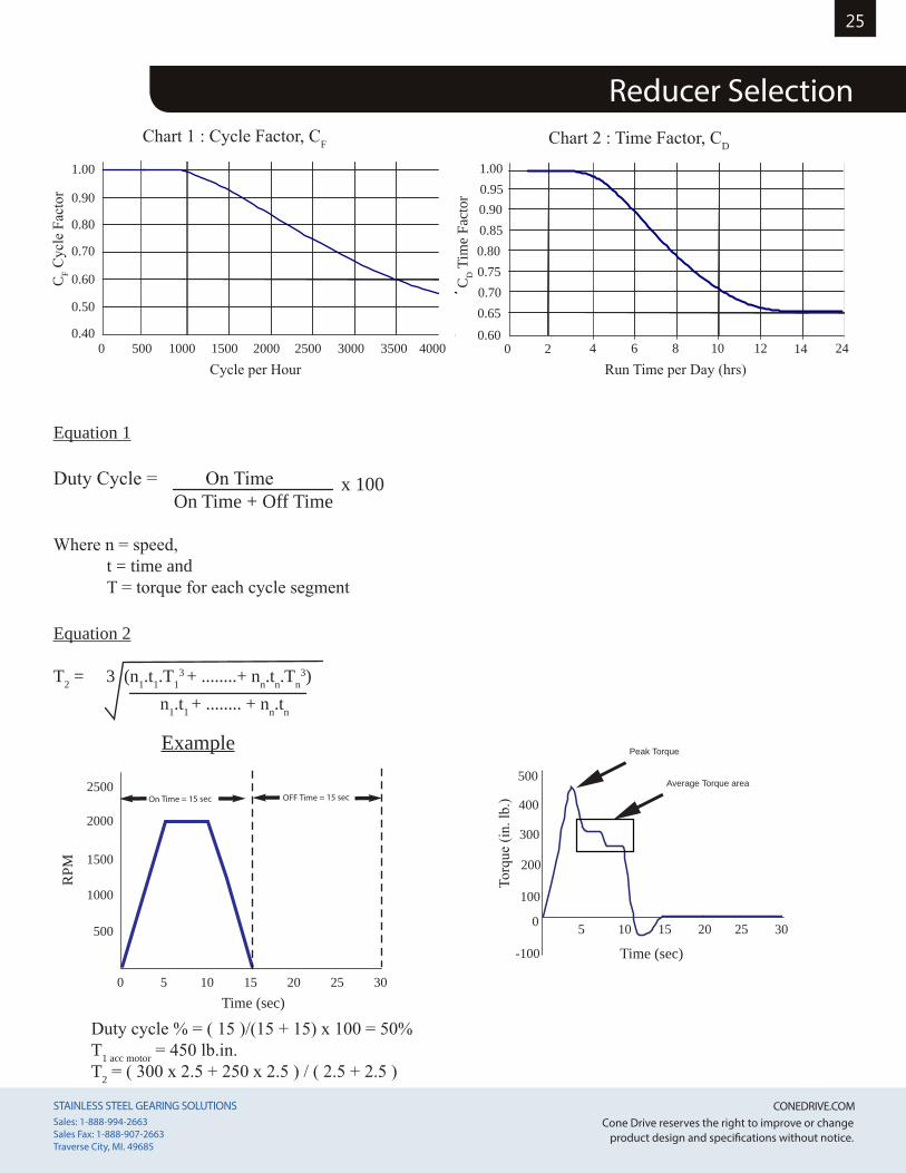
Equation 1
Duty Cycle = On Time x 100 On Time + Off Time
Where n = speed, t = time and T = torque for each cycle segment
Equation 2
T2 = 3 (n1.t1.T13 + ........+ nn.tn.Tn
3) n1.t1 + ........ + nn.tn
On Time = 15 sec OFF Time = 15 sec
Time (sec)0 5 10 15 20 25 30
2500
2000
1500
1000
500
RPM
Duty cycle % = ( 15 )/(15 + 15) x 100 = 50%T1 acc motor = 450 lb.in.T2 = ( 300 x 2.5 + 250 x 2.5 ) / ( 2.5 + 2.5 )
Example
0.90
1.00
0.85
0.95
0.800.750.700.650.60
2 0 4 6 8 10 12 14 24
CD T
ime
Fact
or
Chart 2 : Time Factor, CD
Run Time per Day (hrs)
1.00
0.90
0.80
0.70
0.60
0.50
0.40500 0 1000 1500 2000 2500 3000 3500 4000
CF C
ycle
Fac
tor
Chart 1 : Cycle Factor, CF
Cycle per Hour
Peak Torque
Average Torque area500
5 10 15 20 25 30
100
200
300
400
0
-100
Torq
ue (i
n. lb
.)
Time (sec)
Reducer Selection
STAINLESS STEEL GEARING SOLUTIONS CONEDRIVE.COM STAINLESS STEEL GEARING SOLUTIONS CONEDRIVE.COM Sales: 1-888-994-2663Sales Fax: 1-888-907-2663Traverse City, MI. 49685
Cone Drive reserves the right to improve or change product design and specifications without notice.
26So
lid O
utpu
t Sha
ft V
ersi
onHo
llow
Out
put S
haft
Ver
sion
Shrin
k Di
sc S
haft
Ver
sion
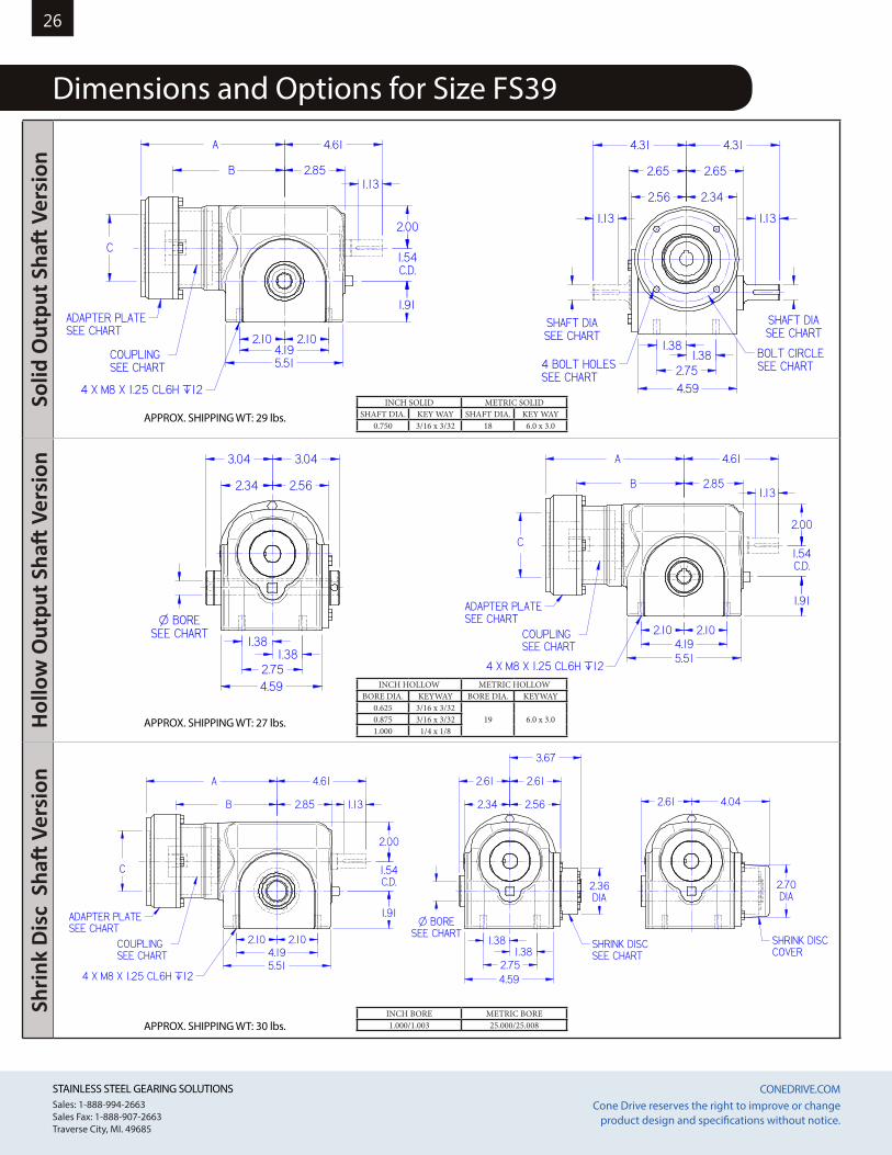
Dimensions and Options for Size FS39
1.54C.D.
2.34
2.61
2.56
2.61
4 X M8 X 1.25 CL6H `12
1.381.38
2.754.59
2.10 2.104.195.51
1.91
2.00
COUPLINGSEE CHART
B
A
2.85
4.61
C
O BORESEE CHART
3.67
SHRINK DISCSEE CHART
SHRINK DISCCOVER
4.042.61
2.70DIA
2.36DIA
ADAPTER PLATESEE CHART
1.13
INCH SOLID METRIC SOLIDSHAFT DIA. KEY WAY SHAFT DIA. KEY WAY
0.750 3/16 x 3/32 18 6.0 x 3.0
INCH BORE METRIC BORE1.000/1.003 25.000/25.008
INCH HOLLOW METRIC HOLLOWBORE DIA. KEYWAY BORE DIA. KEYWAY
0.625 3/16 x 3/3219 6.0 x 3.00.875 3/16 x 3/32
1.000 1/4 x 1/8APPROX. SHIPPING WT: 27 lbs.
APPROX. SHIPPING WT: 30 lbs.
1.54C.D.
4 X M8 X 1.25 CL6H `12
2.56 2.34
2.65
4.31
SHAFT DIASEE CHART
2.10 2.104.195.51
1.91
2.00
COUPLINGSEE CHART
B
A
C
2.85
4.61
1.381.38
2.754.59
BOLT CIRCLESEE CHART4 BOLT HOLES
SEE CHART
ADAPTER PLATESEE CHART
SHAFT DIASEE CHART
2.65
4.31
1.13
1.131.13
APPROX. SHIPPING WT: 29 lbs.
1.54C.D.
4 X M8 X 1.25 CL6H `12
2.56 2.34
2.65
4.31
SHAFT DIASEE CHART
2.10 2.104.195.51
1.91
2.00
COUPLINGSEE CHART
B
A
C
2.85
4.61
1.381.38
2.754.59
BOLT CIRCLESEE CHART4 BOLT HOLES
SEE CHART
ADAPTER PLATESEE CHART
SHAFT DIASEE CHART
2.65
4.31
1.13
1.131.13
1.54C.D.
2.34
3.04
2.56
3.04
4 X M8 X 1.25 CL6H `12
1.381.38
2.754.59
2.10 2.104.195.51
1.91
2.00
COUPLINGSEE CHART
B
A
2.85
4.61
C
O BORESEE CHART
ADAPTER PLATESEE CHART
1.13
1.54C.D.
2.34
3.04
2.56
3.04
4 X M8 X 1.25 CL6H `12
1.381.38
2.754.59
2.10 2.104.195.51
1.91
2.00
COUPLINGSEE CHART
B
A
2.85
4.61
C
O BORESEE CHART
ADAPTER PLATESEE CHART
1.13
STAINLESS STEEL GEARING SOLUTIONS CONEDRIVE.COM STAINLESS STEEL GEARING SOLUTIONS CONEDRIVE.COM Sales: 1-888-994-2663Sales Fax: 1-888-907-2663Traverse City, MI. 49685
Cone Drive reserves the right to improve or change product design and specifications without notice.
27O
utpu
t Fla
nge
Vers
ion
Side
Mou
nt V
ersi
onFo
ot M
ount
Ver
sion
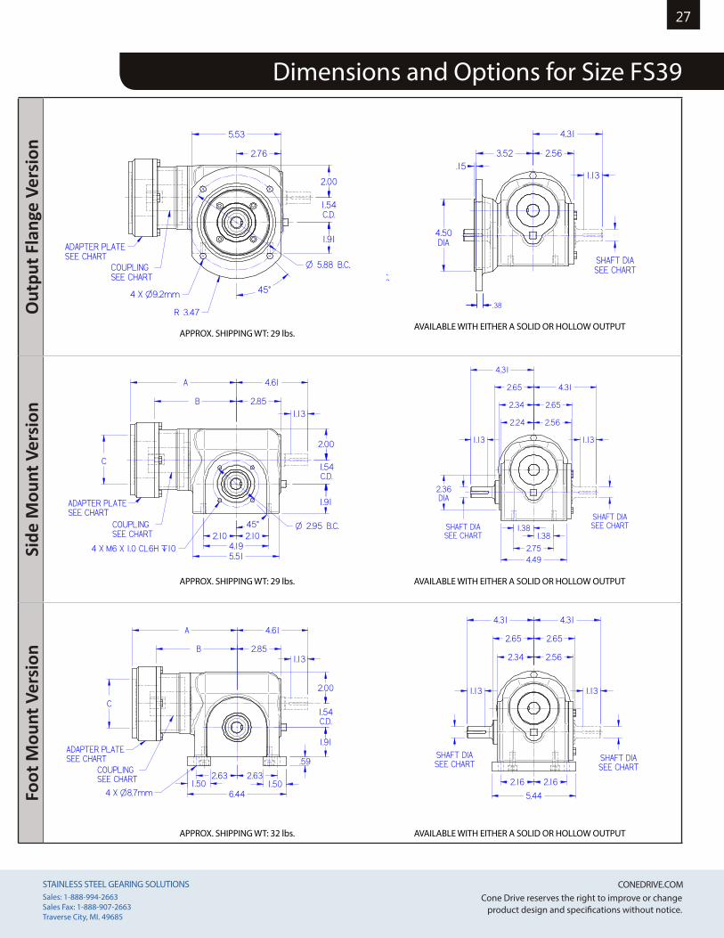
Dimensions and Options for Size FS39
1.54C.D.
4 X O9.2mm
O 5.88 B.C.
3.52
4.50DIA
R 3.47
.15
2.00
1.91
COUPLINGSEE CHART
2.56
4.31
ADAPTER PLATESEE CHART
45°
2.76
5.53
1.13
SHAFT DIASEE CHART
.38
1.54C.D.
4 X O9.2mm
O 5.88 B.C.
3.52
4.50DIA
R 3.47
.15
2.00
1.91
COUPLINGSEE CHART
2.56
4.31
ADAPTER PLATESEE CHART
45°
2.76
5.53
1.13
SHAFT DIASEE CHART
.38
1.54C.D.
4 X M6 X 1.0 CL6H `10
O 2.95 B.C.
2.34
2.36DIA
45°
2.24
1.91
2.00
2.10 2.104.195.51
1.381.38
2.754.49
COUPLINGSEE CHART
B
A
C
2.85
4.612.65
4.31
2.56
2.65
ADAPTER PLATESEE CHART
SHAFT DIASEE CHART
4.31
SHAFT DIASEE CHART
1.13
1.13 1.13
1.54C.D.
4 X M6 X 1.0 CL6H `10
O 2.95 B.C.
2.34
2.36DIA
45°
2.24
1.91
2.00
2.10 2.104.195.51
1.381.38
2.754.49
COUPLINGSEE CHART
B
A
C
2.85
4.612.65
4.31
2.56
2.65
ADAPTER PLATESEE CHART
SHAFT DIASEE CHART
4.31
SHAFT DIASEE CHART
1.13
1.13 1.13
1.54C.D.
4 X O8.7mm
2.632.63
6.441.50 1.50
.59
2.16 2.16
5.44
1.91
2.00
B
A
2.85
4.61
C
2.34
2.65
4.31
2.56
2.65
COUPLINGSEE CHART
ADAPTER PLATESEE CHART
SHAFT DIASEE CHART
SHAFT DIASEE CHART
4.31
1.13 1.13
1.13
1.54C.D.
4 X O8.7mm
2.632.63
6.441.50 1.50
.59
2.16 2.16
5.44
1.91
2.00
B
A
2.85
4.61
C
2.34
2.65
4.31
2.56
2.65
COUPLINGSEE CHART
ADAPTER PLATESEE CHART
SHAFT DIASEE CHART
SHAFT DIASEE CHART
4.31
1.13 1.13
1.13
APPROX. SHIPPING WT: 29 lbs.
APPROX. SHIPPING WT: 29 lbs.
APPROX. SHIPPING WT: 32 lbs.
AVAILABLE WITH EITHER A SOLID OR HOLLOW OUTPUT
AVAILABLE WITH EITHER A SOLID OR HOLLOW OUTPUT
AVAILABLE WITH EITHER A SOLID OR HOLLOW OUTPUT
STAINLESS STEEL GEARING SOLUTIONS CONEDRIVE.COM STAINLESS STEEL GEARING SOLUTIONS CONEDRIVE.COM Sales: 1-888-994-2663Sales Fax: 1-888-907-2663Traverse City, MI. 49685
Cone Drive reserves the right to improve or change product design and specifications without notice.
28So
lid O
utpu
t Sha
ft V
ersi
onHo
llow
Out
put S
haft
Ver
sion
Shrin
k Di
sc S
haft
Ver
sion
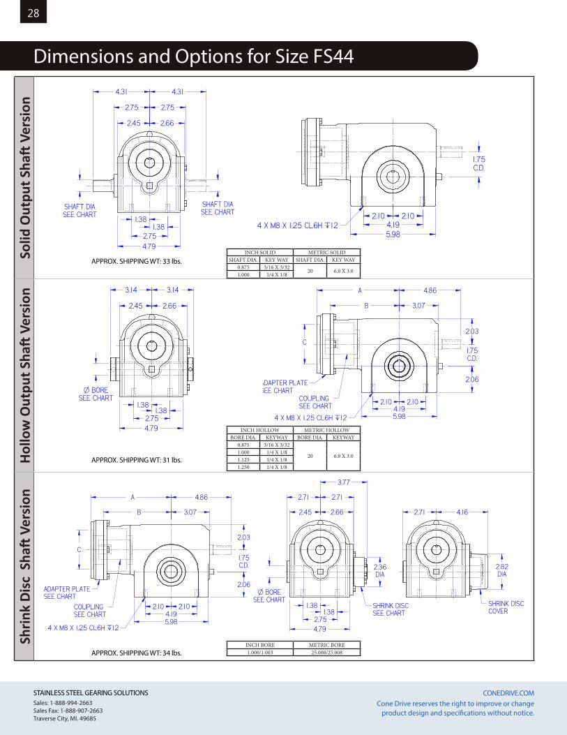
Dimensions and Options for Size FS44
1.75C.D.
4 X M8 X 1.25 CL6H `12
4.31
2.45
2.75
2.66
SHAFT DIASEE CHART
2.10 2.104.195.98
1.381.38
2.754.79
4.31
2.75
SHAFT DIASEE CHART
1.75C.D.
4 X M8 X 1.25 CL6H `12
4.31
2.45
2.75
2.66
SHAFT DIASEE CHART
2.10 2.104.195.98
1.381.38
2.754.79
4.31
2.75
SHAFT DIASEE CHART
1.75C.D.
2.45
3.14
2.66
3.14
4 X M8 X 1.25 CL6H `12
1.381.38
2.754.79
2.10 2.104.195.98
2.06
2.03
COUPLINGSEE CHART
B
A
3.07
4.86
C
O BORESEE CHART
ADAPTER PLATESEE CHART
1.75C.D.
2.45
3.14
2.66
3.14
4 X M8 X 1.25 CL6H `12
1.381.38
2.754.79
2.10 2.104.195.98
2.06
2.03
COUPLINGSEE CHART
B
A
3.07
4.86
C
O BORESEE CHART
ADAPTER PLATESEE CHART
1.75C.D.
2.45
2.71
2.66
2.71
4 X M8 X 1.25 CL6H `12
1.381.38
2.754.79
2.10 2.104.195.98
2.06
2.03
COUPLINGSEE CHART
B
A
3.07
4.86
C
O BORESEE CHART
3.77
SHRINK DISCSEE CHART
SHRINK DISCCOVER
4.162.71
2.82DIA
2.36DIA
ADAPTER PLATESEE CHART
INCH SOLID METRIC SOLIDSHAFT DIA. KEY WAY SHAFT DIA. KEY WAY
0.875 3/16 X 3/3220 6.0 X 3.0
1.000 1/4 X 1/8
INCH BORE METRIC BORE1.000/1.003 25.000/25.008
INCH HOLLOW METRIC HOLLOWBORE DIA. KEYWAY BORE DIA. KEYWAY
0.875 3/16 X 3/32
20 6.0 X 3.01.000 1/4 X 1/81.125 1/4 X 1/81.250 1/4 X 1/8
APPROX. SHIPPING WT: 31 lbs.
APPROX. SHIPPING WT: 34 lbs.
APPROX. SHIPPING WT: 33 lbs.
STAINLESS STEEL GEARING SOLUTIONS CONEDRIVE.COM STAINLESS STEEL GEARING SOLUTIONS CONEDRIVE.COM Sales: 1-888-994-2663Sales Fax: 1-888-907-2663Traverse City, MI. 49685
Cone Drive reserves the right to improve or change product design and specifications without notice.
29
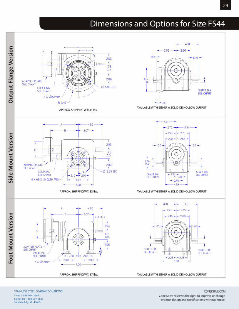
Dimensions and Options for Size FS44
Out
put F
lang
e Ve
rsio
nSi
de M
ount
Ver
sion
Foot
Mou
nt V
ersi
on
1.75C.D.
4 X O9.2mm
O 5.88 B.C.
3.62
4.50DIA
R 3.47
.15
2.03
2.06
COUPLINGSEE CHART
2.66
ADAPTER PLATESEE CHART
45°
2.76
5.53
SHAFT DIASEE CHART
4.31
1.26
.38
1.75C.D.
4 X O9.2mm
O 5.88 B.C.
3.62
4.50DIA
R 3.47
.15
2.03
2.06
COUPLINGSEE CHART
2.66
ADAPTER PLATESEE CHART
45°
2.76
5.53
SHAFT DIASEE CHART
4.31
1.26
.38
1.75C.D.
4 X M6 X 1.0 CL6H `10
O 3.35 B.C.
2.45
2.76DIA
45°
2.35
2.06
2.03
2.10 2.104.19
5.98
1.381.38
2.754.69
COUPLINGSEE CHART
B
A
C
3.07
4.862.75
4.31
2.66
ADAPTER PLATESEE CHART
SHAFT DIASEE CHART
2.75
4.31
1.261.26
SHAFT DIASEE CHART
1.75C.D.
4 X M6 X 1.0 CL6H `10
O 3.35 B.C.
2.45
2.76DIA
45°
2.35
2.06
2.03
2.10 2.104.19
5.98
1.381.38
2.754.69
COUPLINGSEE CHART
B
A
C
3.07
4.862.75
4.31
2.66
ADAPTER PLATESEE CHART
SHAFT DIASEE CHART
2.75
4.31
1.261.26
SHAFT DIASEE CHART
1.75C.D.
4 X O8.7mm
2.882.88
7.00
2.00 2.00
.69
2.25 2.255.68
2.06
2.03
B
A
3.07
4.86
C
2.45
2.75
4.31
2.75
4.31
COUPLINGSEE CHART
ADAPTER PLATESEE CHART
SHAFT DIASEE CHART
SHAFT DIASEE CHART
2.66
1.26 1.26
1.13
1.75C.D.
4 X O8.7mm
2.882.88
7.00
2.00 2.00
.69
2.25 2.255.68
2.06
2.03
B
A
3.07
4.86
C
2.45
2.75
4.31
2.75
4.31
COUPLINGSEE CHART
ADAPTER PLATESEE CHART
SHAFT DIASEE CHART
SHAFT DIASEE CHART
2.66
1.26 1.26
1.13
APPROX. SHIPPING WT: 33 lbs.
APPROX. SHIPPING WT: 33 lbs.
APPROX. SHIPPING WT: 37 lbs.
AVAILABLE WITH EITHER A SOLID OR HOLLOW OUTPUT
AVAILABLE WITH EITHER A SOLID OR HOLLOW OUTPUT
AVAILABLE WITH EITHER A SOLID OR HOLLOW OUTPUT
STAINLESS STEEL GEARING SOLUTIONS CONEDRIVE.COM STAINLESS STEEL GEARING SOLUTIONS CONEDRIVE.COM Sales: 1-888-994-2663Sales Fax: 1-888-907-2663Traverse City, MI. 49685
Cone Drive reserves the right to improve or change product design and specifications without notice.
30So
lid O
utpu
t Sha
ft V
ersi
onHo
llow
Out
put S
haft
Ver
sion
Shrin
k Di
sc S
haft
Ver
sion
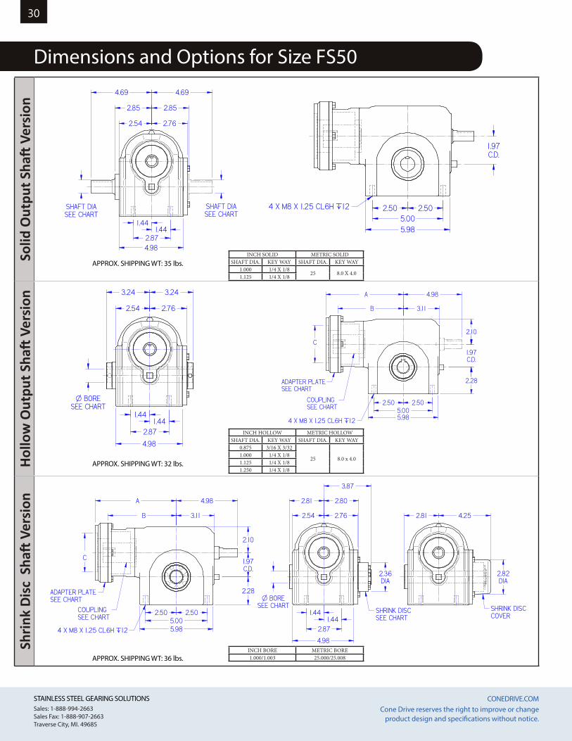
Dimensions and Options for Size FS50
1.97C.D.
4 X M8 X 1.25 CL6H `12
4.69
2.54
2.85
2.76
SHAFT DIASEE CHART
2.50 2.505.005.98
1.441.44
2.874.98
2.85
4.69
SHAFT DIASEE CHART
1.97C.D.
4 X M8 X 1.25 CL6H `12
4.69
2.54
2.85
2.76
SHAFT DIASEE CHART
2.50 2.505.005.98
1.441.44
2.874.98
2.85
4.69
SHAFT DIASEE CHART
1.97C.D.
2.54
3.24
2.76
3.24
4 X M8 X 1.25 CL6H `12
1.441.44
2.87
4.98
2.50 2.505.005.98
2.28
2.10
COUPLINGSEE CHART
B
A
3.11
4.98
C
O BORESEE CHART
ADAPTER PLATESEE CHART
1.97C.D.
2.54
3.24
2.76
3.24
4 X M8 X 1.25 CL6H `12
1.441.44
2.87
4.98
2.50 2.505.005.98
2.28
2.10
COUPLINGSEE CHART
B
A
3.11
4.98
C
O BORESEE CHART
ADAPTER PLATESEE CHART
1.97C.D.
2.54
2.81
2.76
2.80
4 X M8 X 1.25 CL6H `12
1.441.44
2.87
4.98
2.50 2.505.005.98
2.28
2.10
COUPLINGSEE CHART
B
A
3.11
4.98
C
O BORESEE CHART
3.87
SHRINK DISCSEE CHART
SHRINK DISCCOVER
4.252.81
2.82DIA
2.36DIA
ADAPTER PLATESEE CHART
INCH SOLID METRIC SOLIDSHAFT DIA. KEY WAY SHAFT DIA. KEY WAY
1.000 1/4 X 1/825 8.0 X 4.0
1.125 1/4 X 1/8
INCH BORE METRIC BORE1.000/1.003 25.000/25.008
INCH HOLLOW METRIC HOLLOWSHAFT DIA. KEY WAY SHAFT DIA. KEY WAY
0.875 3/16 X 3/32
25 8.0 x 4.01.000 1/4 X 1/81.125 1/4 X 1/81.250 1/4 X 1/8
APPROX. SHIPPING WT: 32 lbs.
APPROX. SHIPPING WT: 36 lbs.
APPROX. SHIPPING WT: 35 lbs.
STAINLESS STEEL GEARING SOLUTIONS CONEDRIVE.COM STAINLESS STEEL GEARING SOLUTIONS CONEDRIVE.COM Sales: 1-888-994-2663Sales Fax: 1-888-907-2663Traverse City, MI. 49685
Cone Drive reserves the right to improve or change product design and specifications without notice.
31
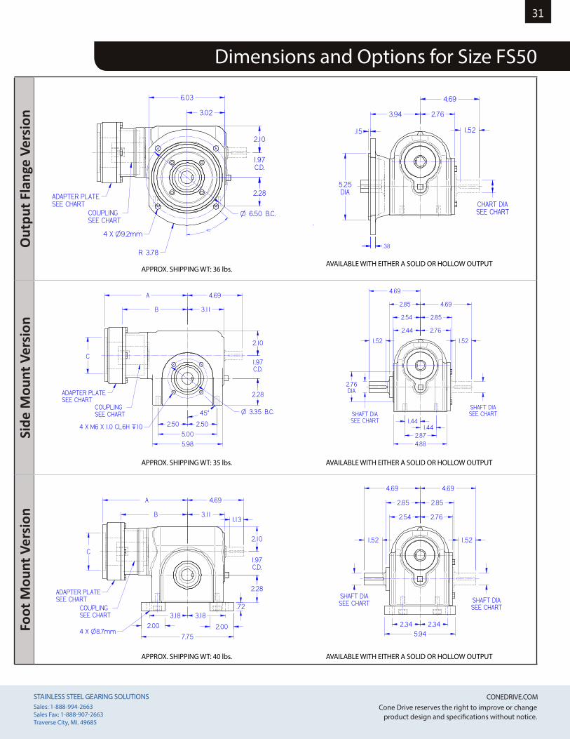
Dimensions and Options for Size FS50
Out
put F
lang
e Ve
rsio
nSi
de M
ount
Ver
sion
Foot
Mou
nt V
ersi
on
1.97C.D.
4 X O9.2mm
O 6.50 B.C.
3.94
5.25DIA
R 3.78
.15
2.10
2.28
COUPLINGSEE CHART
2.76
4.69
ADAPTER PLATESEE CHART
45°
3.02
6.03
1.52
CHART DIASEE CHART
.38
1.97C.D.
4 X O9.2mm
O 6.50 B.C.
3.94
5.25DIA
R 3.78
.15
2.10
2.28
COUPLINGSEE CHART
2.76
4.69
ADAPTER PLATESEE CHART
45°
3.02
6.03
1.52
CHART DIASEE CHART
.38
1.97C.D.
4 X M6 X 1.0 CL6H `10
O 3.35 B.C.
2.54
2.76DIA
45°
2.44
2.28
2.10
2.50 2.50
5.005.98
1.441.44
2.874.88
COUPLINGSEE CHART
B
A
C
3.11
4.692.85
4.69
2.76
ADAPTER PLATESEE CHART
SHAFT DIASEE CHART
2.85
4.69
SHAFT DIASEE CHART
1.52 1.52
1.97C.D.
4 X M6 X 1.0 CL6H `10
O 3.35 B.C.
2.54
2.76DIA
45°
2.44
2.28
2.10
2.50 2.50
5.005.98
1.441.44
2.874.88
COUPLINGSEE CHART
B
A
C
3.11
4.692.85
4.69
2.76
ADAPTER PLATESEE CHART
SHAFT DIASEE CHART
2.85
4.69
SHAFT DIASEE CHART
1.52 1.52
1.97C.D.
4 X O8.7mm
3.183.18
7.75
2.00 2.00
.72
2.34 2.345.94
2.28
2.10
B
A
3.11
4.69
C
2.54
2.85
4.69
2.85
4.69
COUPLINGSEE CHART
ADAPTER PLATESEE CHART
SHAFT DIASEE CHART SHAFT DIA
SEE CHART
2.76
1.52 1.52
1.13
1.97C.D.
4 X O8.7mm
3.183.18
7.75
2.00 2.00
.72
2.34 2.345.94
2.28
2.10
B
A
3.11
4.69
C
2.54
2.85
4.69
2.85
4.69
COUPLINGSEE CHART
ADAPTER PLATESEE CHART
SHAFT DIASEE CHART SHAFT DIA
SEE CHART
2.76
1.52 1.52
1.13
APPROX. SHIPPING WT: 35 lbs.
APPROX. SHIPPING WT: 36 lbs.
APPROX. SHIPPING WT: 40 lbs.
AVAILABLE WITH EITHER A SOLID OR HOLLOW OUTPUT
AVAILABLE WITH EITHER A SOLID OR HOLLOW OUTPUT
AVAILABLE WITH EITHER A SOLID OR HOLLOW OUTPUT
STAINLESS STEEL GEARING SOLUTIONS CONEDRIVE.COM STAINLESS STEEL GEARING SOLUTIONS CONEDRIVE.COM Sales: 1-888-994-2663Sales Fax: 1-888-907-2663Traverse City, MI. 49685
Cone Drive reserves the right to improve or change product design and specifications without notice.
32So
lid O
utpu
t Sha
ft V
ersi
onHo
llow
Out
put S
haft
Ver
sion
Shrin
k Di
sc S
haft
Ver
sion
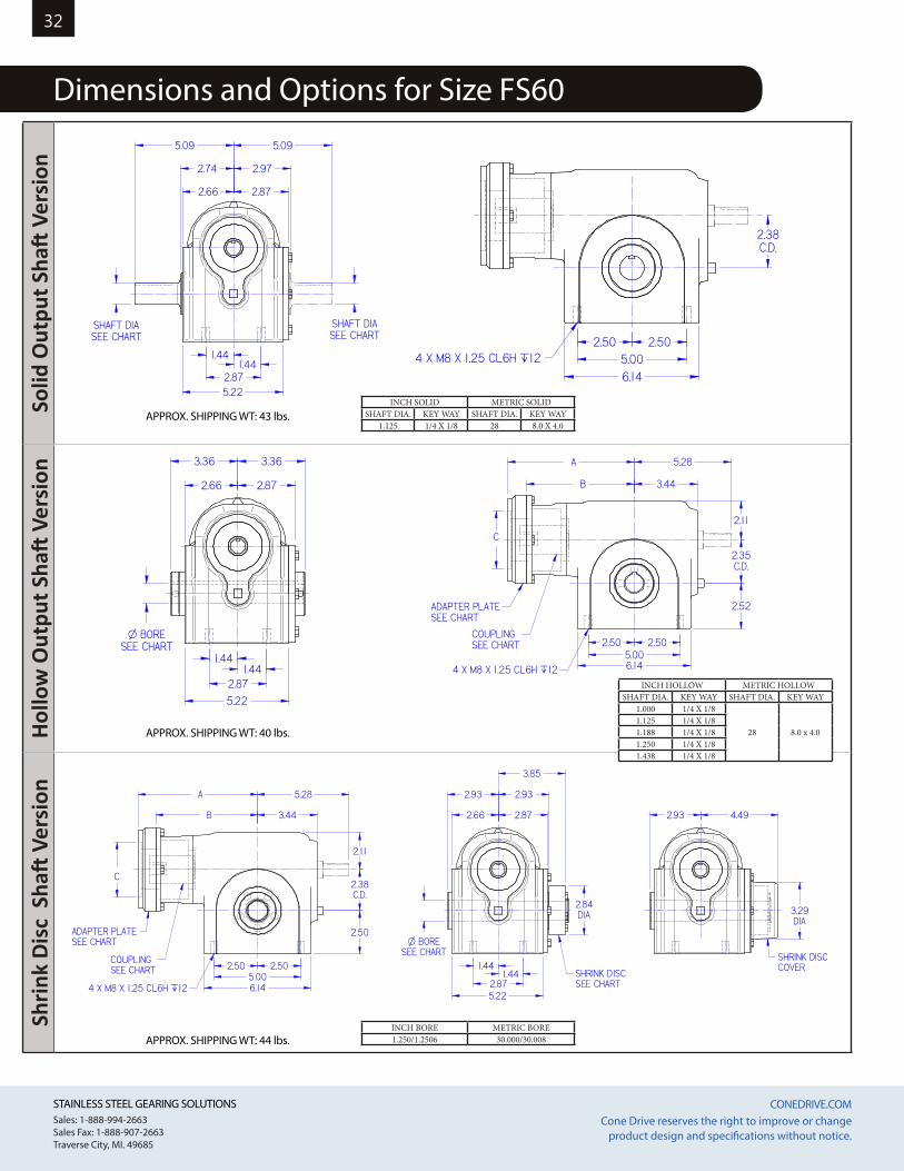
Dimensions and Options for Size FS60
2.38C.D.
4 X M8 X 1.25 CL6H `12
5.09
2.66
2.74
2.87
SHAFT DIASEE CHART
2.50 2.505.006.14
1.441.44
2.875.22
2.97
5.09
SHAFT DIASEE CHART
2.38C.D.
4 X M8 X 1.25 CL6H `12
5.09
2.66
2.74
2.87
SHAFT DIASEE CHART
2.50 2.505.006.14
1.441.44
2.875.22
2.97
5.09
SHAFT DIASEE CHART
2.35C.D.
2.66
3.36
2.87
3.36
4 X M8 X 1.25 CL6H `12
1.441.44
2.875.22
2.50 2.505.006.14
2.52
2.11
COUPLINGSEE CHART
B
A
3.44
5.28
C
O BORESEE CHART
ADAPTER PLATESEE CHART
2.35C.D.
2.66
3.36
2.87
3.36
4 X M8 X 1.25 CL6H `12
1.441.44
2.875.22
2.50 2.505.006.14
2.52
2.11
COUPLINGSEE CHART
B
A
3.44
5.28
C
O BORESEE CHART
ADAPTER PLATESEE CHART
2.38C.D.
2.66
2.93
2.87
2.93
4 X M8 X 1.25 CL6H `12
1.441.44
2.875.22
2.50 2.505.006.14
2.50
2.11
COUPLINGSEE CHART
B
A
3.44
5.28
C
O BORESEE CHART
3.85
SHRINK DISCSEE CHART
SHRINK DISCCOVER
4.492.93
3.29DIA
2.84DIA
ADAPTER PLATESEE CHART
INCH SOLID METRIC SOLIDSHAFT DIA. KEY WAY SHAFT DIA. KEY WAY
1.125 1/4 X 1/8 28 8.0 X 4.0
INCH BORE METRIC BORE1.250/1.2506 30.000/30.008
INCH HOLLOW METRIC HOLLOWSHAFT DIA. KEY WAY SHAFT DIA. KEY WAY
1.000 1/4 X 1/8
28 8.0 x 4.01.125 1/4 X 1/81.188 1/4 X 1/81.250 1/4 X 1/81.438 1/4 X 1/8
APPROX. SHIPPING WT: 40 lbs.
APPROX. SHIPPING WT: 44 lbs.
APPROX. SHIPPING WT: 43 lbs.
STAINLESS STEEL GEARING SOLUTIONS CONEDRIVE.COM STAINLESS STEEL GEARING SOLUTIONS CONEDRIVE.COM Sales: 1-888-994-2663Sales Fax: 1-888-907-2663Traverse City, MI. 49685
Cone Drive reserves the right to improve or change product design and specifications without notice.
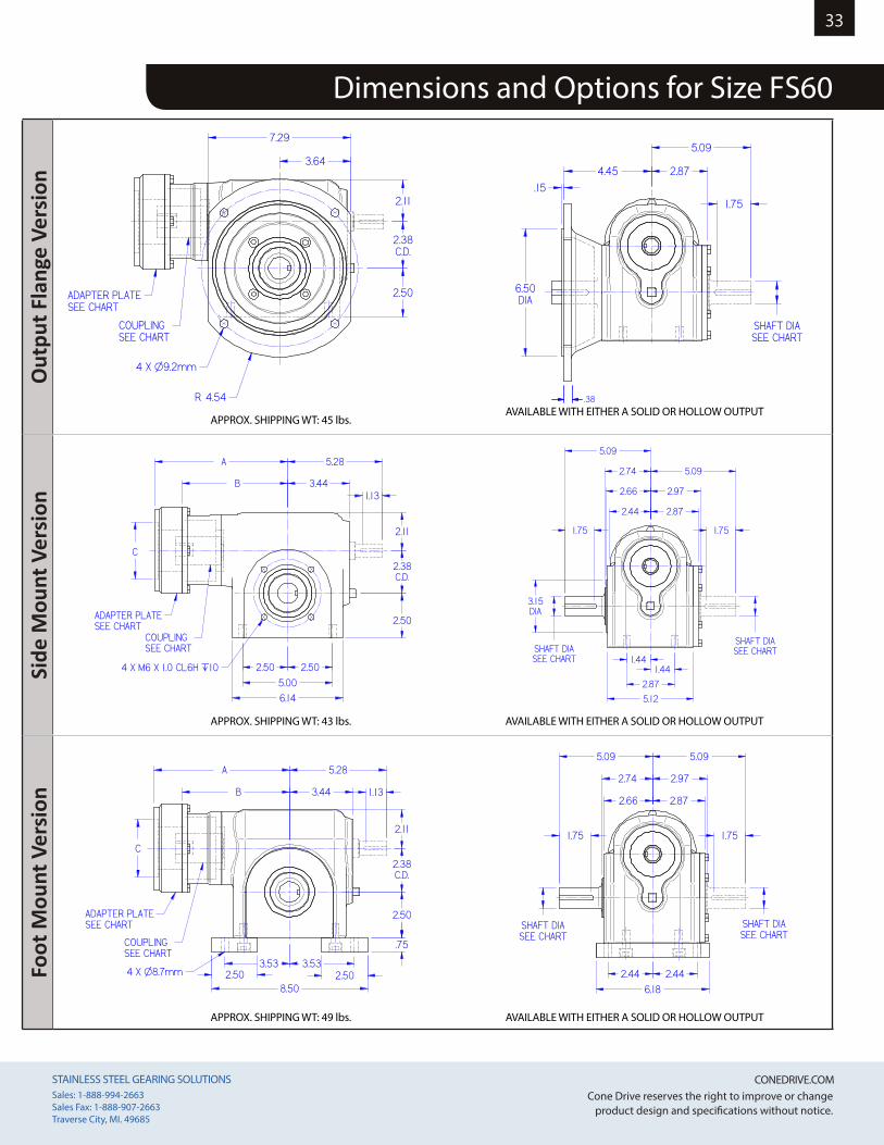
33
Dimensions and Options for Size FS60
Out
put F
lang
e Ve
rsio
nSi
de M
ount
Ver
sion
Foot
Mou
nt V
ersi
on
4 X O9.2mm
4.45
6.50DIA
R 4.54
.15
2.11
COUPLINGSEE CHART
2.87
5.09
ADAPTER PLATESEE CHART
3.64
7.29
2.38C.D.
2.50SHAFT DIASEE CHART
1.75
.38
4 X O9.2mm
4.45
6.50DIA
R 4.54
.15
2.11
COUPLINGSEE CHART
2.87
5.09
ADAPTER PLATESEE CHART
3.64
7.29
2.38C.D.
2.50SHAFT DIASEE CHART
1.75
.38
2.38C.D.
4 X M6 X 1.0 CL6H `10
2.66
3.15DIA
2.44
2.50
2.11
2.50 2.50
5.006.14
1.441.44
2.87
5.12
COUPLINGSEE CHART
B
A
C
3.44
5.282.74
5.09
2.87
ADAPTER PLATESEE CHART
SHAFT DIASEE CHART
2.97
5.09
SHAFT DIASEE CHART
1.13
1.75 1.75
2.38C.D.
4 X M6 X 1.0 CL6H `10
2.66
3.15DIA
2.44
2.50
2.11
2.50 2.50
5.006.14
1.441.44
2.87
5.12
COUPLINGSEE CHART
B
A
C
3.44
5.282.74
5.09
2.87
ADAPTER PLATESEE CHART
SHAFT DIASEE CHART
2.97
5.09
SHAFT DIASEE CHART
1.13
1.75 1.75
2.38C.D.
4 X O8.7mm3.533.53
8.502.50 2.50
.75
2.44 2.446.18
2.50
2.11
B
A
3.44
5.28
C
2.66
2.74
5.09
COUPLINGSEE CHART
ADAPTER PLATESEE CHART SHAFT DIA
SEE CHART
2.87
2.97
5.09
SHAFT DIASEE CHART
1.75 1.75
1.13
2.38C.D.
4 X O8.7mm3.533.53
8.502.50 2.50
.75
2.44 2.446.18
2.50
2.11
B
A
3.44
5.28
C
2.66
2.74
5.09
COUPLINGSEE CHART
ADAPTER PLATESEE CHART SHAFT DIA
SEE CHART
2.87
2.97
5.09
SHAFT DIASEE CHART
1.75 1.75
1.13
APPROX. SHIPPING WT: 43 lbs.
APPROX. SHIPPING WT: 45 lbs.
APPROX. SHIPPING WT: 49 lbs.
AVAILABLE WITH EITHER A SOLID OR HOLLOW OUTPUT
AVAILABLE WITH EITHER A SOLID OR HOLLOW OUTPUT
AVAILABLE WITH EITHER A SOLID OR HOLLOW OUTPUT

STAINLESS STEEL GEARING SOLUTIONS CONEDRIVE.COM STAINLESS STEEL GEARING SOLUTIONS CONEDRIVE.COM Sales: 1-888-994-2663Sales Fax: 1-888-907-2663Traverse City, MI. 49685
Cone Drive reserves the right to improve or change product design and specifications without notice.
34So
lid O
utpu
t Sha
ft V
ersi
onHo
llow
Out
put S
haft
Ver
sion
Shrin
k Di
sc S
haft
Ver
sion
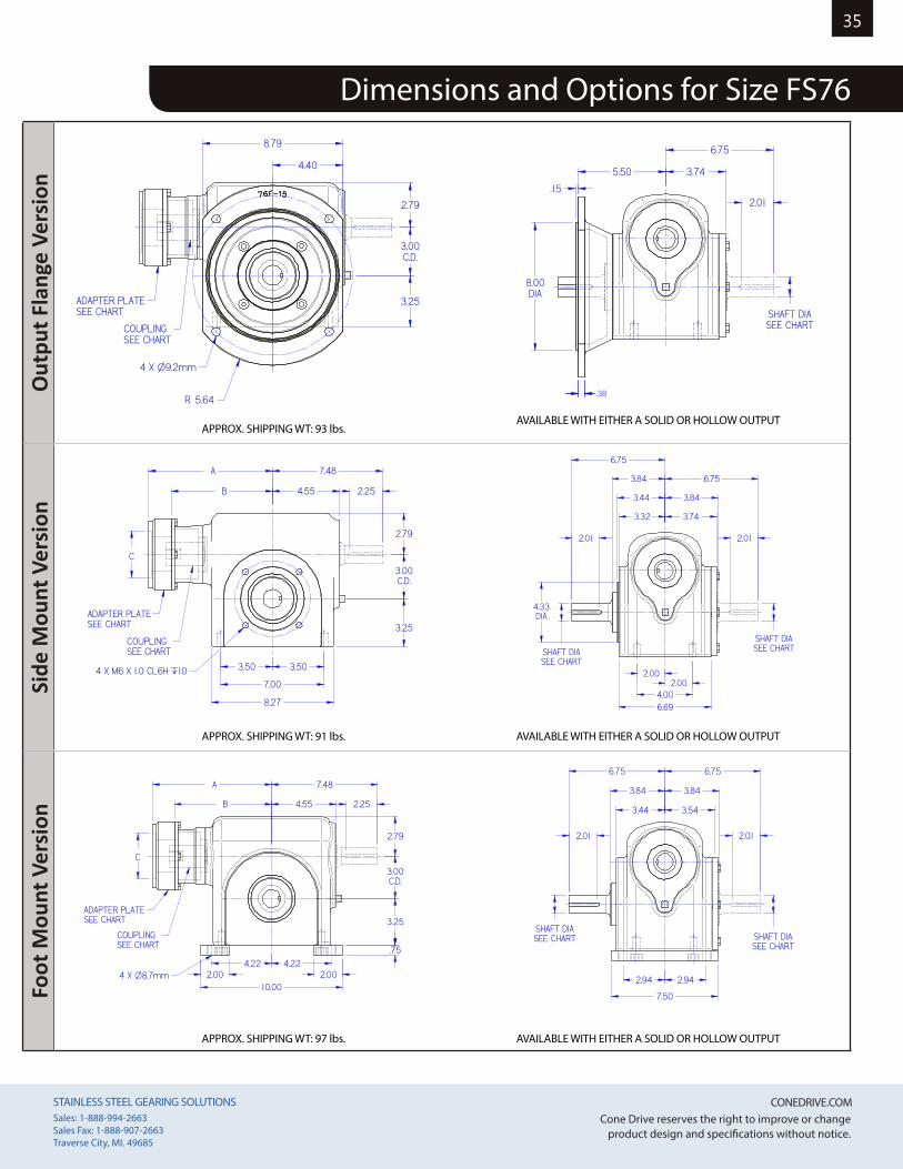
Dimensions and Options for Size FS76
3.00C.D.
4 X M8 X 1.25 CL6H `12
6.75
3.44
3.84
3.74
SHAFT DIASEE CHART3.50 3.50
7.008.27
2.002.00
4.00
6.79
3.84
6.75
SHAFT DIASEE CHART
3.00C.D.
4 X M8 X 1.25 CL6H `12
6.75
3.44
3.84
3.74
SHAFT DIASEE CHART3.50 3.50
7.008.27
2.002.00
4.00
6.79
3.84
6.75
SHAFT DIASEE CHART
3.00C.D.
3.44
4.32
3.74
4.32
4 X M8 X 1.25 CL6H `122.00
2.004.006.79
3.50 3.507.00
8.27
3.25
2.79
COUPLINGSEE CHART
B
A
4.55
7.63
C
O BORESEE CHART
ADAPTER PLATESEE CHART
3.00C.D.
3.44
4.32
3.74
4.32
4 X M8 X 1.25 CL6H `122.00
2.004.006.79
3.50 3.507.00
8.27
3.25
2.79
COUPLINGSEE CHART
B
A
4.55
7.63
C
O BORESEE CHART
ADAPTER PLATESEE CHART
3.00C.D.
3.44
3.84
3.74
3.84
4 X M8 X 1.25 CL6H `12
2.002.00
4.006.79
3.50 3.507.008.27
3.25
2.79
COUPLINGSEE CHART
B
A
4.55
7.63
C
O BORESEE CHART
4.86
SHRINK DISCSEE CHART
SHRINK DISCCOVER
5.513.84
4.00DIA
3.15DIA
ADAPTER PLATESEE CHART
INCH SOLID METRIC SOLIDSHAFT DIA. KEY WAY SHAFT DIA. KEY WAY
1.250 1/4 X 1/835 10 x 4.4
1.500 3/8 X 3/16
INCH BORE METRIC BORE1.4375/1.438 35.002/35.018
INCH HOLLOW METRIC HOLLOWSHAFT DIA. KEY WAY SHAFT DIA. KEY WAY
1.438 3/8 X 3/16
35 10 x 4.41.750 3/8 X 3/161.938 1/2 X 1/42.188 1/2 X 1/4
APPROX. SHIPPING WT: 82 lbs.
APPROX. SHIPPING WT: 88 lbs.
APPROX. SHIPPING WT: 91 lbs.
STAINLESS STEEL GEARING SOLUTIONS CONEDRIVE.COM STAINLESS STEEL GEARING SOLUTIONS CONEDRIVE.COM Sales: 1-888-994-2663Sales Fax: 1-888-907-2663Traverse City, MI. 49685
Cone Drive reserves the right to improve or change product design and specifications without notice.
35
Dimensions and Options for Size FS76
Out
put F
lang
e Ve
rsio
nSi
de M
ount
Ver
sion
Foot
Mou
nt V
ersi
on
4 X O9.2mm
5.50
8.00DIA
R 5.64
.15
2.79
COUPLINGSEE CHART
3.74
6.75
ADAPTER PLATESEE CHART
4.40
8.79
3.00C.D.
3.25 SHAFT DIASEE CHART
2.01
.384 X O9.2mm
5.50
8.00DIA
R 5.64
.15
2.79
COUPLINGSEE CHART
3.74
6.75
ADAPTER PLATESEE CHART
4.40
8.79
3.00C.D.
3.25 SHAFT DIASEE CHART
2.01
.38
3.00C.D.
4 X M6 X 1.0 CL6H `10
3.44
4.33DIA
3.32
3.25
2.79
3.50 3.50
7.00
8.27
2.002.00
4.006.69
COUPLINGSEE CHART
B
A
C
4.55
7.48
3.84
6.75
3.74
ADAPTER PLATESEE CHART
SHAFT DIASEE CHART
6.75
SHAFT DIASEE CHART
3.84
2.01 2.01
2.25
3.00C.D.
4 X M6 X 1.0 CL6H `10
3.44
4.33DIA
3.32
3.25
2.79
3.50 3.50
7.00
8.27
2.002.00
4.006.69
COUPLINGSEE CHART
B
A
C
4.55
7.48
3.84
6.75
3.74
ADAPTER PLATESEE CHART
SHAFT DIASEE CHART
6.75
SHAFT DIASEE CHART
3.84
2.01 2.01
2.25
3.00C.D.
4 X O8.7mm4.224.22
10.002.00 2.00
.75
2.94 2.94
7.50
3.25
2.79
B
A
4.55
7.48
C
3.44
3.84
6.75
COUPLINGSEE CHART
ADAPTER PLATESEE CHART SHAFT DIA
SEE CHART
3.54
3.84
6.75
SHAFT DIASEE CHART
2.25
2.012.01
3.00C.D.
4 X O8.7mm4.224.22
10.002.00 2.00
.75
2.94 2.94
7.50
3.25
2.79
B
A
4.55
7.48
C
3.44
3.84
6.75
COUPLINGSEE CHART
ADAPTER PLATESEE CHART SHAFT DIA
SEE CHART
3.54
3.84
6.75
SHAFT DIASEE CHART
2.25
2.012.01
APPROX. SHIPPING WT: 91 lbs.
APPROX. SHIPPING WT: 93 lbs.
APPROX. SHIPPING WT: 97 lbs.
AVAILABLE WITH EITHER A SOLID OR HOLLOW OUTPUT
AVAILABLE WITH EITHER A SOLID OR HOLLOW OUTPUT
AVAILABLE WITH EITHER A SOLID OR HOLLOW OUTPUT

STAINLESS STEEL GEARING SOLUTIONS CONEDRIVE.COM STAINLESS STEEL GEARING SOLUTIONS CONEDRIVE.COM Sales: 1-888-994-2663Sales Fax: 1-888-907-2663Traverse City, MI. 49685
Cone Drive reserves the right to improve or change product design and specifications without notice.
36
Ratings for Size FS39
RATIO CAPACITYInput Speed , RPM
500 1000 2000 3000Lb-In Nm Lb-In Nm Lb-In Nm Lb-In Nm
5
Input Torque Taccel 139 15.7 126 14.3 109 12.3 93 10.5Input Torque Trun 128 14.4 108 12.3 81 9.1 66 7.5IT Thermal, Ttherm 127 14.4 108 12.2 78 8.9 45 5.1
Output Torque Taccel 631 71.3 581 65.7 499 56.4 422 47.7Output Torque Trun 581 65.7 499 56.4 370 41.8 300 33.9
Efficiency % 91 92 92 91
7.5
Input Torque Taccel 114 12.9 104 11.7 91 10.3 79 8.9Input Torque Trun 106 12.0 91 10.3 68 7.7 56 6.3IT Thermal, Ttherm 106 12.0 91 10.2 67 7.6 40 4.6
Output Torque Taccel 763 86.2 707 79.9 620 70.1 530 59.9Output Torque Trun 707 79.9 620 70.1 461 52.1 376 42.5
Efficiency % 89 91 91 90
10
Input Torque Taccel 94 10.7 85 9.6 77 8.7 67 7.6Input Torque Trun 88 10.0 77 8.7 58 6.5 48 5.4IT Thermal, Ttherm 88 10.0 77 8.7 58 6.5 37 4.2
Output Torque Taccel 822 92.9 768 86.8 689 77.9 593 67.0Output Torque Trun 768 86.8 689 77.9 517 58.4 424 47.9
Efficiency % 87 90 90 89
15
Input Torque Taccel 76 8.5 69 7.7 62 7.1 55 6.2Input Torque Trun 72 8.1 62 7.0 47 5.3 39 4.4IT Thermal, Ttherm 72 8.1 62 7.0 47 5.3 32 3.6
Output Torque Taccel 955 108 905 102 823 93.0 713 80.6Output Torque Trun 905 102 823 93.0 623 70.4 510 57.6
Efficiency % 84 88 88 87
20
Input Torque Taccel 57 6.4 53 6.0 47 5.4 42 4.8Input Torque Trun 55 6.2 48 5.4 36 4.1 30 3.4IT Thermal, Ttherm 55 6.2 48 5.4 36 4.1 26 3.0
Output Torque Taccel 927 105 892 101 806 91.1 706 79.8Output Torque Trun 892 101 806 91.1 617 69.7 505 57.1
Efficiency % 81 84 85 84
25
Input Torque Taccel 45 5.1 43 4.9 38 4.3 34 3.8Input Torque Trun 44 5.0 39 4.4 29 3.3 24 2.8IT Thermal, Ttherm 44 5.0 39 4.4 29 3.3 24 2.8
Output Torque Taccel 909 103 896 101 804 90.9 703 79.4Output Torque Trun 896 101 804 90.9 615 69.5 503 56.8
Efficiency % 81 83 84 83
30
Input Torque Taccel 39 4.4 35 3.9 32 3.6 29 3.2Input Torque Trun 37 4.2 32 3.6 25 2.8 20 2.3IT Thermal, Ttherm 37 4.2 32 3.6 25 2.8 20 2.2
Output Torque Taccel 864 97.6 823 93.0 768 86.8 673 76.0Output Torque Trun 823 93.0 768 86.8 588 66.4 481 54.4
Efficiency % 74 79 80 79
40
Input Torque Taccel 28 3.2 26 2.9 24 2.7 22 2.4Input Torque Trun 28 3.1 24 2.8 18 2.1 15 1.7IT Thermal, Ttherm 28 3.1 24 2.8 18 2.1 15 1.7
Output Torque Taccel 786 88.8 784 88.6 734 82.9 644 72.8Output Torque Trun 784 88.6 734 82.9 561 63.4 459 51.9
Efficiency % 70 75 76 75
50
Input Torque Taccel 22 2.5 21 2.4 19 2.2 17 2.0Input Torque Trun 22 2.5 20 2.2 15 1.7 12 1.4IT Thermal, Ttherm 22 2.5 20 2.2 15 1.7 12 1.4
Output Torque Taccel 764 86.3 764 86.3 707 79.9 620 70.1Output Torque Trun 764 86.3 707 79.9 541 61.1 442 49.9
Efficiency % 68 72 73 72
60
Input Torque Taccel 19 2.1 17 2.0 16 1.8 14 1.6Input Torque Trun 19 2.1 16 1.8 12 1.4 10 1.2IT Thermal, Ttherm 19 2.1 16 1.8 12 1.4 10 1.2
Output Torque Taccel 725 81.9 721 81.5 678 76.6 596 67.3Output Torque Trun 721 81.5 678 76.6 520 58.8 424 47.9
Efficiency % 64 69 70 69
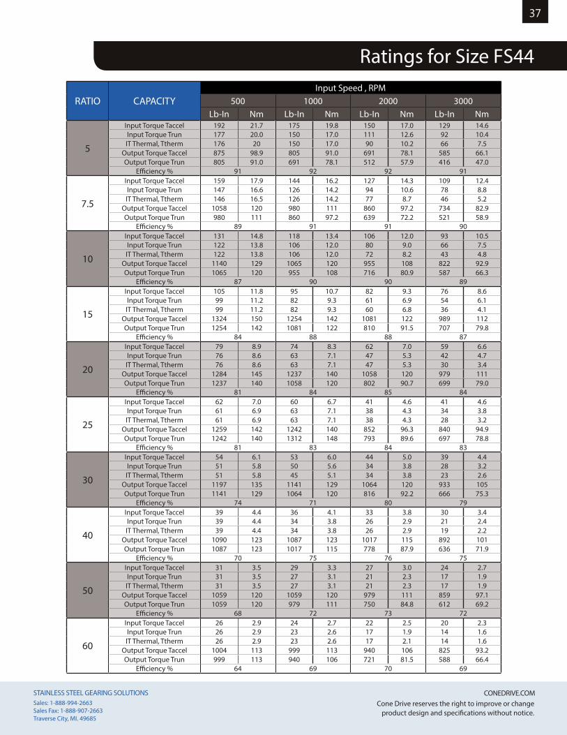
STAINLESS STEEL GEARING SOLUTIONS CONEDRIVE.COM STAINLESS STEEL GEARING SOLUTIONS CONEDRIVE.COM Sales: 1-888-994-2663Sales Fax: 1-888-907-2663Traverse City, MI. 49685
Cone Drive reserves the right to improve or change product design and specifications without notice.
37
Ratings for Size FS44
RATIO CAPACITYInput Speed , RPM
500 1000 2000 3000Lb-In Nm Lb-In Nm Lb-In Nm Lb-In Nm
5
Input Torque Taccel 192 21.7 175 19.8 150 17.0 129 14.6Input Torque Trun 177 20.0 150 17.0 111 12.6 92 10.4IT Thermal, Ttherm 176 20 150 17.0 90 10.2 66 7.5
Output Torque Taccel 875 98.9 805 91.0 691 78.1 585 66.1Output Torque Trun 805 91.0 691 78.1 512 57.9 416 47.0
Efficiency % 91 92 92 91
7.5
Input Torque Taccel 159 17.9 144 16.2 127 14.3 109 12.4Input Torque Trun 147 16.6 126 14.2 94 10.6 78 8.8IT Thermal, Ttherm 146 16.5 126 14.2 77 8.7 46 5.2
Output Torque Taccel 1058 120 980 111 860 97.2 734 82.9Output Torque Trun 980 111 860 97.2 639 72.2 521 58.9
Efficiency % 89 91 91 90
10
Input Torque Taccel 131 14.8 118 13.4 106 12.0 93 10.5Input Torque Trun 122 13.8 106 12.0 80 9.0 66 7.5IT Thermal, Ttherm 122 13.8 106 12.0 72 8.2 43 4.8
Output Torque Taccel 1140 129 1065 120 955 108 822 92.9Output Torque Trun 1065 120 955 108 716 80.9 587 66.3
Efficiency % 87 90 90 89
15
Input Torque Taccel 105 11.8 95 10.7 82 9.3 76 8.6Input Torque Trun 99 11.2 82 9.3 61 6.9 54 6.1IT Thermal, Ttherm 99 11.2 82 9.3 60 6.8 36 4.1
Output Torque Taccel 1324 150 1254 142 1081 122 989 112Output Torque Trun 1254 142 1081 122 810 91.5 707 79.8
Efficiency % 84 88 88 87
20
Input Torque Taccel 79 8.9 74 8.3 62 7.0 59 6.6Input Torque Trun 76 8.6 63 7.1 47 5.3 42 4.7IT Thermal, Ttherm 76 8.6 63 7.1 47 5.3 30 3.4
Output Torque Taccel 1284 145 1237 140 1058 120 979 111Output Torque Trun 1237 140 1058 120 802 90.7 699 79.0
Efficiency % 81 84 85 84
25
Input Torque Taccel 62 7.0 60 6.7 41 4.6 41 4.6Input Torque Trun 61 6.9 63 7.1 38 4.3 34 3.8IT Thermal, Ttherm 61 6.9 63 7.1 38 4.3 28 3.2
Output Torque Taccel 1259 142 1242 140 852 96.3 840 94.9Output Torque Trun 1242 140 1312 148 793 89.6 697 78.8
Efficiency % 81 83 84 83
30
Input Torque Taccel 54 6.1 53 6.0 44 5.0 39 4.4Input Torque Trun 51 5.8 50 5.6 34 3.8 28 3.2IT Thermal, Ttherm 51 5.8 45 5.1 34 3.8 23 2.6
Output Torque Taccel 1197 135 1141 129 1064 120 933 105Output Torque Trun 1141 129 1064 120 816 92.2 666 75.3
Efficiency % 74 71 80 79
40
Input Torque Taccel 39 4.4 36 4.1 33 3.8 30 3.4Input Torque Trun 39 4.4 34 3.8 26 2.9 21 2.4IT Thermal, Ttherm 39 4.4 34 3.8 26 2.9 19 2.2
Output Torque Taccel 1090 123 1087 123 1017 115 892 101Output Torque Trun 1087 123 1017 115 778 87.9 636 71.9
Efficiency % 70 75 76 75
50
Input Torque Taccel 31 3.5 29 3.3 27 3.0 24 2.7Input Torque Trun 31 3.5 27 3.1 21 2.3 17 1.9IT Thermal, Ttherm 31 3.5 27 3.1 21 2.3 17 1.9
Output Torque Taccel 1059 120 1059 120 979 111 859 97.1Output Torque Trun 1059 120 979 111 750 84.8 612 69.2
Efficiency % 68 72 73 72
60
Input Torque Taccel 26 2.9 24 2.7 22 2.5 20 2.3Input Torque Trun 26 2.9 23 2.6 17 1.9 14 1.6IT Thermal, Ttherm 26 2.9 23 2.6 17 2.1 14 1.6
Output Torque Taccel 1004 113 999 113 940 106 825 93.2Output Torque Trun 999 113 940 106 721 81.5 588 66.4
Efficiency % 64 69 70 69

STAINLESS STEEL GEARING SOLUTIONS CONEDRIVE.COM STAINLESS STEEL GEARING SOLUTIONS CONEDRIVE.COM Sales: 1-888-994-2663Sales Fax: 1-888-907-2663Traverse City, MI. 49685
Cone Drive reserves the right to improve or change product design and specifications without notice.
38
Ratings for Size FS50
RATIO CAPACITYInput Speed , RPM
500 1000 2000 3000Lb-In Nm Lb-In Nm Lb-In Nm Lb-In Nm
5
Input Torque Taccel 257 29.0 234 26.4 201 22.7 106 12.0Input Torque Trun 236 26.7 201 22.7 149 16.8 123 13.9IT Thermal, Ttherm 236 26.6 187 21.1 92 10.4 66 7.5
Output Torque Taccel 1168 132 1075 121 923 104 481 54.4Output Torque Trun 1075 121 923 104 684 77.3 556 62.8
Efficiency % 91 92 92 91
7.5
Input Torque Taccel 212 23.9 168 19.0 169 19.1 104 11.7Input Torque Trun 196 22.1 192 21.7 126 14.2 146 16.5IT Thermal, Ttherm 197 22.2 166 18.7 79 8.9 47 5.4
Output Torque Taccel 1412 160 1149 130 1149 130 695 78.5Output Torque Trun 1308 148 1308 148 853 96.4 981 111
Efficiency % 89 91 91 90
10
Input Torque Taccel 175 19.8 158 17.9 142 16.0 124 14.0Input Torque Trun 163 18.5 142 16.0 106 12.0 88 10.0IT Thermal, Ttherm 164 18.5 142 16.0 74 8.3 44 4.9
Output Torque Taccel 1522 172 1422 161 1275 144 1098 124Output Torque Trun 1422 161 1275 144 956 108 784 88.6
Efficiency % 87 90 90 89
15
Input Torque Taccel 140 15.8 127 14.3 116 13.1 102 11.5Input Torque Trun 133 15.0 115 13.0 88 9.9 73 8.2IT Thermal, Ttherm 132 14.9 115 13.0 62 7.0 37 4.2
Output Torque Taccel 1768 200 1675 189 1524 172 1321 149Output Torque Trun 1675 189 1524 172 1154 130 944 107
Efficiency % 84 88 88 87
20
Input Torque Taccel 105 11.9 98 11.1 88 9.9 78 8.8Input Torque Trun 101 11.5 89 10.0 67 7.6 56 6.3IT Thermal, Ttherm 102 11.5 89 10.0 49 5.6 30 3.4
Output Torque Taccel 1715 194 1652 187 1491 168 1307 148Output Torque Trun 1652 187 1491 168 1143 129 934 106
Efficiency % 81 84 85 84
25
Input Torque Taccel 83 9.4 80 9.0 71 8.0 63 7.1Input Torque Trun 82 9.3 71 8.1 54 6.1 45 5.1IT Thermal, Ttherm 82 9.3 71 8.0 46 5.2 29 3.2
Output Torque Taccel 1682 190 1659 187 1488 168 1302 147Output Torque Trun 1659 187 1488 168 1138 129 930 105
Efficiency % 81 83 84 83
30
Input Torque Taccel 72 8.1 64 7.2 59 6.7 53 6.0Input Torque Trun 68 7.7 60 6.8 45 5.1 38 4.3IT Thermal, Ttherm 69 7.7 60 6.8 37 4.2 23 2.6
Output Torque Taccel 1598 181 1524 172 1422 161 1246 141Output Torque Trun 1524 172 1422 161 1089 123 890 101
Efficiency % 74 79 80 79
40
Input Torque Taccel 52 5.8 48 5.4 45 5.1 40 4.5Input Torque Trun 52 5.8 45 5.1 34 3.9 28 3.2IT Thermal, Ttherm 52 5.8 45 5.1 31 3.5 20 2.2
Output Torque Taccel 1455 164 1452 164 1359 154 1192 135Output Torque Trun 1452 164 1359 154 1039 117 850 96.1
Efficiency % 70 75 76 75
50
Input Torque Taccel 41 4.7 39 4.4 36 4.1 32 3.6Input Torque Trun 41 4.7 36 4.1 27 3.1 23 2.6IT Thermal, Ttherm 41 4.7 36 4.1 27 3.1 18 2.0
Output Torque Taccel 1415 160 1415 160 1308 148 1148 130Output Torque Trun 1415 160 1308 148 1002 113 818 92.4
Efficiency % 68 72 73 72
60
Input Torque Taccel 35 3.9 32 3.6 30 3.4 19 2.2Input Torque Trun 35 3.9 30 3.4 23 2.6 27 3.0IT Thermal, Ttherm 35 3.9 30 3.4 23 2.8 16 1.8
Output Torque Taccel 1341 152 1334 151 1256 142 786 88.8Output Torque Trun 1334 151 1256 142 963 109 1102 125
Efficiency % 64 69 70 69

STAINLESS STEEL GEARING SOLUTIONS CONEDRIVE.COM STAINLESS STEEL GEARING SOLUTIONS CONEDRIVE.COM Sales: 1-888-994-2663Sales Fax: 1-888-907-2663Traverse City, MI. 49685
Cone Drive reserves the right to improve or change product design and specifications without notice.
39
Ratings for Size FS60
RATIO CAPACITYInput Speed , RPM
500 1000 2000 3000Lb-In Nm Lb-In Nm Lb-In Nm Lb-In Nm
5
Input Torque Taccel 443 50.1 398 45.0 327 37.0 275 31.1Input Torque Trun 403 45.5 327 36.9 237 26.8 192 21.8IT Thermal, Ttherm 340 38.4 191 21.6 94 10.7 66 7.5
Output Torque Taccel 2017 228 1833 207 1503 170 1245 141Output Torque Trun 1833 207 1503 170 1091 123 872 98.5
Efficiency % 91 92 92 91
7.5
Input Torque Taccel 365 41.3 327 37.0 276 31.2 232 26.2Input Torque Trun 334 37.8 275 31.1 200 22.6 163 18.4IT Thermal, Ttherm 278 31.4 170 19.2 80 9.1 49 5.5
Output Torque Taccel 2439 276 2232 252 1876 212 1554 176Output Torque Trun 2232 252 1876 212 1359 154 1092 123
Efficiency % 89 91 91 90
10
Input Torque Taccel 302 34.1 270 30.5 224 25.3 197 22.2Input Torque Trun 280 31.6 224 25.3 169 19.1 139 15.7IT Thermal, Ttherm 236 26.6 153 17.3 76 8.6 45 5.1
Output Torque Taccel 2625 297 2433 275 2013 227 1744 197Output Torque Trun 2433 275 2013 227 1523 172 1228 139
Efficiency % 87 90 90 89
15
Input Torque Taccel 241 27.2 217 24.6 158 17.8 124 14.1Input Torque Trun 227 25.7 158 17.8 126 14.2 101 11.4IT Thermal, Ttherm 194 21.9 128 14.4 63 7.1 38 4.3
Output Torque Taccel 3044 344 2869 324 2079 235 1616 183Output Torque Trun 2869 324 2079 235 1661 188 1309 148
Efficiency % 84 88 88 87
20
Input Torque Taccel 181 20.5 168 19.0 144 16.3 97 11.0Input Torque Trun 174 19.6 63 7.1 91 10.3 78 8.8IT Thermal, Ttherm 165 18.6 63 7.1 51 5.7 31 3.5
Output Torque Taccel 2954 334 2830 320 2445 276 1622 183Output Torque Trun 2830 320 1058 120 1546 175 1299 147
Efficiency % 81 84 85 84
25
Input Torque Taccel 143 16.2 136 15.4 97 11.0 82 9.2Input Torque Trun 140 15.8 98 11.0 72 8.2 62 7.0IT Thermal, Ttherm 140 15.8 92 10.4 48 5.4 29 3.3
Output Torque Taccel 2897 327 2837 321 2034 229.8 1688 191Output Torque Trun 2837 321 2034 230 1520 171.7 1279 145
Efficiency % 81 83 84 83
30
Input Torque Taccel 124 14.0 106 12.0 84 9.5 78 8.9Input Torque Trun 113 12.8 85 9.6 65 7.3 59 6.7IT Thermal, Ttherm 113 12.8 74 8.4 38 4.3 24 2.7
Output Torque Taccel 2753 311 2524 285 2023 229 1850 209Output Torque Trun 2524 285 2023 229 1548 175 1396 158
Efficiency % 74 79 80 79
40
Input Torque Taccel 89 10.1 83 9.3 68 7.6 59 6.6Input Torque Trun 88 10.0 68 7.7 50 5.7 43 4.9IT Thermal, Ttherm 88 10.0 62 7.0 32 3.6 20 2.3
Output Torque Taccel 2510 284 2488 281 2052 232 1750 198Output Torque Trun 2488 281 2052 232 1530 173 1285 145
Efficiency % 70 75 76 75
50
Input Torque Taccel 71 8.0 67 7.6 59 6.7 51 5.8Input Torque Trun 71 8.0 55 6.3 42 4.8 36 4.0IT Thermal, Ttherm 71 8.0 55 6.2 28 3.2 18 2.0
Output Torque Taccel 2427 274 2424 274 2150 243 1825 206Output Torque Trun 2424 274 2004 226 1539 174 1282 145
Efficiency % 68 72 73 72
60
Input Torque Taccel 60 6.8 55 6.2 47 5.4 43 4.8Input Torque Trun 59 6.7 48 5.4 36 4.1 30 3.4IT Thermal, Ttherm 59 6.7 48 5.4 25 3.1 16 1.8
Output Torque Taccel 2314 261 2286 258 1991 225 1753 198Output Torque Trun 2286 258 1991 225 1529 173 1231 139
Efficiency % 64 69 70 69
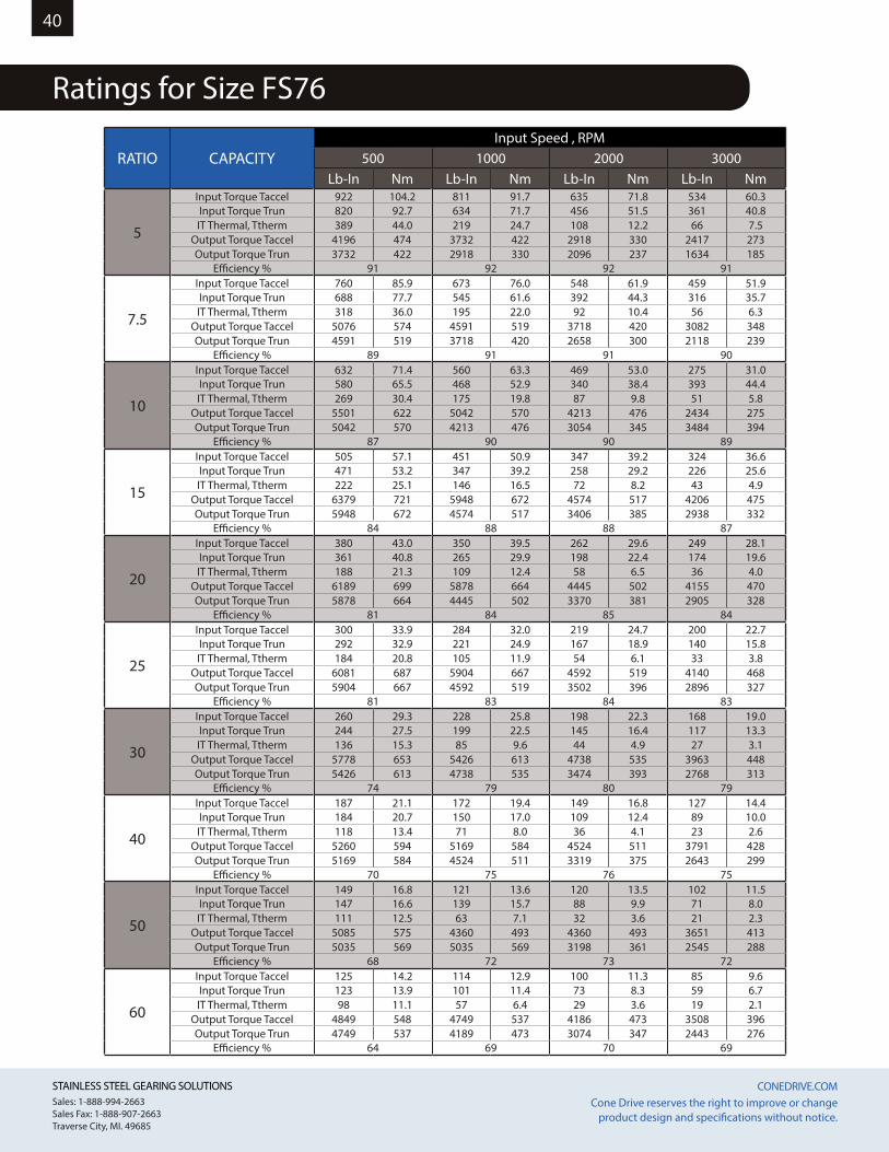
STAINLESS STEEL GEARING SOLUTIONS CONEDRIVE.COM STAINLESS STEEL GEARING SOLUTIONS CONEDRIVE.COM Sales: 1-888-994-2663Sales Fax: 1-888-907-2663Traverse City, MI. 49685
Cone Drive reserves the right to improve or change product design and specifications without notice.
40
Ratings for Size FS76
RATIO CAPACITYInput Speed , RPM
500 1000 2000 3000Lb-In Nm Lb-In Nm Lb-In Nm Lb-In Nm
5
Input Torque Taccel 922 104.2 811 91.7 635 71.8 534 60.3Input Torque Trun 820 92.7 634 71.7 456 51.5 361 40.8IT Thermal, Ttherm 389 44.0 219 24.7 108 12.2 66 7.5
Output Torque Taccel 4196 474 3732 422 2918 330 2417 273Output Torque Trun 3732 422 2918 330 2096 237 1634 185
Efficiency % 91 92 92 91
7.5
Input Torque Taccel 760 85.9 673 76.0 548 61.9 459 51.9Input Torque Trun 688 77.7 545 61.6 392 44.3 316 35.7IT Thermal, Ttherm 318 36.0 195 22.0 92 10.4 56 6.3
Output Torque Taccel 5076 574 4591 519 3718 420 3082 348Output Torque Trun 4591 519 3718 420 2658 300 2118 239
Efficiency % 89 91 91 90
10
Input Torque Taccel 632 71.4 560 63.3 469 53.0 275 31.0Input Torque Trun 580 65.5 468 52.9 340 38.4 393 44.4IT Thermal, Ttherm 269 30.4 175 19.8 87 9.8 51 5.8
Output Torque Taccel 5501 622 5042 570 4213 476 2434 275Output Torque Trun 5042 570 4213 476 3054 345 3484 394
Efficiency % 87 90 90 89
15
Input Torque Taccel 505 57.1 451 50.9 347 39.2 324 36.6Input Torque Trun 471 53.2 347 39.2 258 29.2 226 25.6IT Thermal, Ttherm 222 25.1 146 16.5 72 8.2 43 4.9
Output Torque Taccel 6379 721 5948 672 4574 517 4206 475Output Torque Trun 5948 672 4574 517 3406 385 2938 332
Efficiency % 84 88 88 87
20
Input Torque Taccel 380 43.0 350 39.5 262 29.6 249 28.1Input Torque Trun 361 40.8 265 29.9 198 22.4 174 19.6IT Thermal, Ttherm 188 21.3 109 12.4 58 6.5 36 4.0
Output Torque Taccel 6189 699 5878 664 4445 502 4155 470Output Torque Trun 5878 664 4445 502 3370 381 2905 328
Efficiency % 81 84 85 84
25
Input Torque Taccel 300 33.9 284 32.0 219 24.7 200 22.7Input Torque Trun 292 32.9 221 24.9 167 18.9 140 15.8IT Thermal, Ttherm 184 20.8 105 11.9 54 6.1 33 3.8
Output Torque Taccel 6081 687 5904 667 4592 519 4140 468Output Torque Trun 5904 667 4592 519 3502 396 2896 327
Efficiency % 81 83 84 83
30
Input Torque Taccel 260 29.3 228 25.8 198 22.3 168 19.0Input Torque Trun 244 27.5 199 22.5 145 16.4 117 13.3IT Thermal, Ttherm 136 15.3 85 9.6 44 4.9 27 3.1
Output Torque Taccel 5778 653 5426 613 4738 535 3963 448Output Torque Trun 5426 613 4738 535 3474 393 2768 313
Efficiency % 74 79 80 79
40
Input Torque Taccel 187 21.1 172 19.4 149 16.8 127 14.4Input Torque Trun 184 20.7 150 17.0 109 12.4 89 10.0IT Thermal, Ttherm 118 13.4 71 8.0 36 4.1 23 2.6
Output Torque Taccel 5260 594 5169 584 4524 511 3791 428Output Torque Trun 5169 584 4524 511 3319 375 2643 299
Efficiency % 70 75 76 75
50
Input Torque Taccel 149 16.8 121 13.6 120 13.5 102 11.5Input Torque Trun 147 16.6 139 15.7 88 9.9 71 8.0IT Thermal, Ttherm 111 12.5 63 7.1 32 3.6 21 2.3
Output Torque Taccel 5085 575 4360 493 4360 493 3651 413Output Torque Trun 5035 569 5035 569 3198 361 2545 288
Efficiency % 68 72 73 72
60
Input Torque Taccel 125 14.2 114 12.9 100 11.3 85 9.6Input Torque Trun 123 13.9 101 11.4 73 8.3 59 6.7IT Thermal, Ttherm 98 11.1 57 6.4 29 3.6 19 2.1
Output Torque Taccel 4849 548 4749 537 4186 473 3508 396Output Torque Trun 4749 537 4189 473 3074 347 2443 276
Efficiency % 64 69 70 69
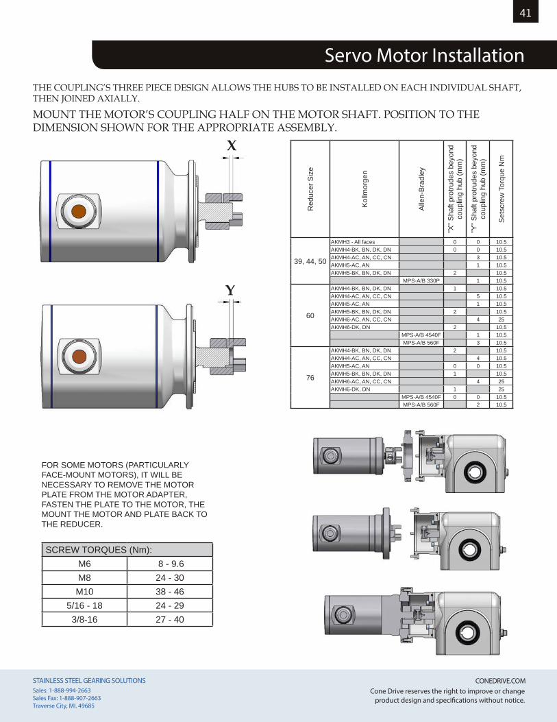
STAINLESS STEEL GEARING SOLUTIONS CONEDRIVE.COM STAINLESS STEEL GEARING SOLUTIONS CONEDRIVE.COM Sales: 1-888-994-2663Sales Fax: 1-888-907-2663Traverse City, MI. 49685
Cone Drive reserves the right to improve or change product design and specifications without notice.
41
Servo Motor InstallationTHE COUPLING’S THREE PIECE DESIGN ALLOWS THE HUBS TO BE INSTALLED ON EACH INDIVIDUAL SHAFT, THEN JOINED AXIALLY.
MOUNT THE MOTOR’S COUPLING HALF ON THE MOTOR SHAFT. POSITION TO THE DIMENSION SHOWN FOR THE APPROPRIATE ASSEMBLY.
Red
ucer
Siz
e
Kollm
orge
n
Alle
n-Br
adle
y
"X" S
haft
prot
rude
s be
yond
co
uplin
g hu
b (m
m)
"Y" S
haft
prot
rude
s be
yond
co
uplin
g hu
b (m
m)
Sets
crew
Tor
que
Nm
39, 44, 50
AKMH3 - All faces 0 0 10.5AKMH4-BK, BN, DK, DN 0 0 10.5AKMH4-AC, AN, CC, CN 3 10.5AKMH5-AC, AN 1 10.5AKMH5-BK, BN, DK, DN 2 10.5
MPS-A/B 330P 1 10.5
60
AKMH4-BK, BN, DK, DN 1 10.5AKMH4-AC, AN, CC, CN 5 10.5AKMH5-AC, AN 1 10.5AKMH5-BK, BN, DK, DN 2 10.5AKMH6-AC, AN, CC, CN 4 25AKMH6-DK, DN 2 10.5
MPS-A/B 4540F 1 10.5MPS-A/B 560F 3 10.5
76
AKMH4-BK, BN, DK, DN 2 10.5AKMH4-AC, AN, CC, CN 4 10.5AKMH5-AC, AN 0 0 10.5AKMH5-BK, BN, DK, DN 1 10.5AKMH6-AC, AN, CC, CN 4 25AKMH6-DK, DN 1 25
MPS-A/B 4540F 0 0 10.5MPS-A/B 560F 2 10.5
X
Y
FOR SOME MOTORS (PARTICULARLY FACE-MOUNT MOTORS), IT WILL BE NECESSARY TO REMOVE THE MOTOR PLATE FROM THE MOTOR ADAPTER, FASTEN THE PLATE TO THE MOTOR, THE MOUNT THE MOTOR AND PLATE BACK TO THE REDUCER.
SCREW TORQUES (Nm):M6 8 - 9.6M8 24 - 30
M10 38 - 465/16 - 18 24 - 293/8-16 27 - 40
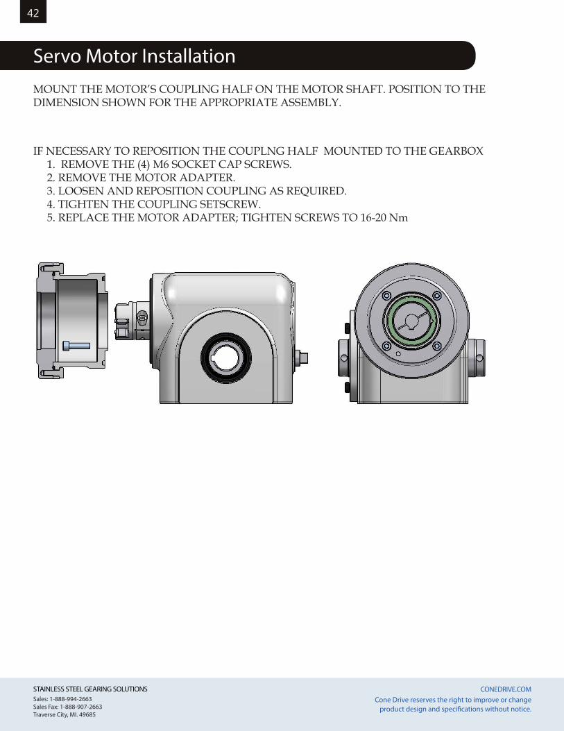
STAINLESS STEEL GEARING SOLUTIONS CONEDRIVE.COM STAINLESS STEEL GEARING SOLUTIONS CONEDRIVE.COM Sales: 1-888-994-2663Sales Fax: 1-888-907-2663Traverse City, MI. 49685
Cone Drive reserves the right to improve or change product design and specifications without notice.
42
Servo Motor InstallationMOUNT THE MOTOR’S COUPLING HALF ON THE MOTOR SHAFT. POSITION TO THE DIMENSION SHOWN FOR THE APPROPRIATE ASSEMBLY.
IF NECESSARY TO REPOSITION THE COUPLNG HALF MOUNTED TO THE GEARBOX 1. REMOVE THE (4) M6 SOCKET CAP SCREWS. 2. REMOVE THE MOTOR ADAPTER. 3. LOOSEN AND REPOSITION COUPLING AS REQUIRED. 4. TIGHTEN THE COUPLING SETSCREW. 5. REPLACE THE MOTOR ADAPTER; TIGHTEN SCREWS TO 16-20 Nm
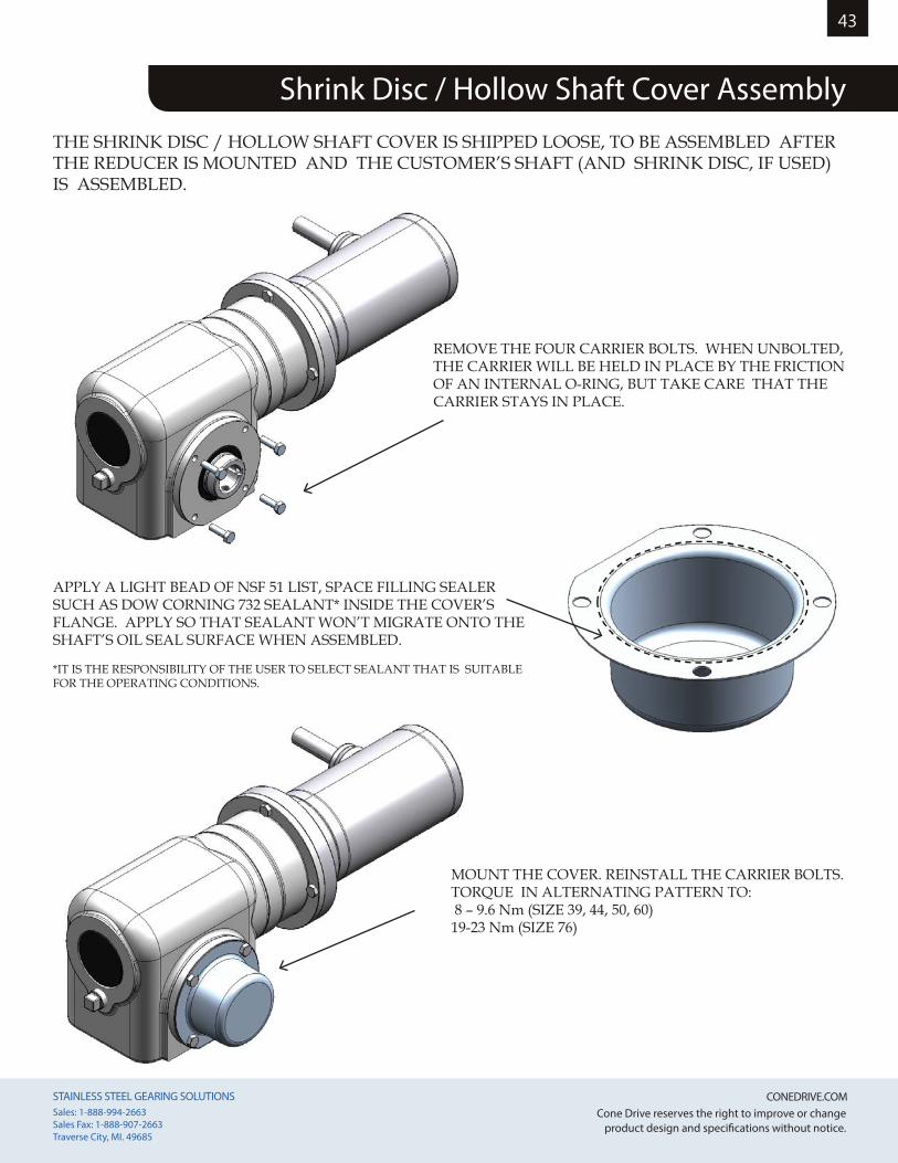
STAINLESS STEEL GEARING SOLUTIONS CONEDRIVE.COM STAINLESS STEEL GEARING SOLUTIONS CONEDRIVE.COM Sales: 1-888-994-2663Sales Fax: 1-888-907-2663Traverse City, MI. 49685
Cone Drive reserves the right to improve or change product design and specifications without notice.
43
THE SHRINK DISC / HOLLOW SHAFT COVER IS SHIPPED LOOSE, TO BE ASSEMBLED AFTER THE REDUCER IS MOUNTED AND THE CUSTOMER’S SHAFT (AND SHRINK DISC, IF USED) IS ASSEMBLED.
MOUNT THE COVER. REINSTALL THE CARRIER BOLTS. TORQUE IN ALTERNATING PATTERN TO: 8 – 9.6 Nm (SIZE 39, 44, 50, 60)19-23 Nm (SIZE 76)
APPLY A LIGHT BEAD OF NSF 51 LIST, SPACE FILLING SEALER SUCH AS DOW CORNING 732 SEALANT* INSIDE THE COVER’S FLANGE. APPLY SO THAT SEALANT WON’T MIGRATE ONTO THE SHAFT’S OIL SEAL SURFACE WHEN ASSEMBLED.
*IT IS THE RESPONSIBILITY OF THE USER TO SELECT SEALANT THAT IS SUITABLE FOR THE OPERATING CONDITIONS.
Shrink Disc / Hollow Shaft Cover Assembly
REMOVE THE FOUR CARRIER BOLTS. WHEN UNBOLTED, THE CARRIER WILL BE HELD IN PLACE BY THE FRICTION OF AN INTERNAL O-RING, BUT TAKE CARE THAT THE CARRIER STAYS IN PLACE.
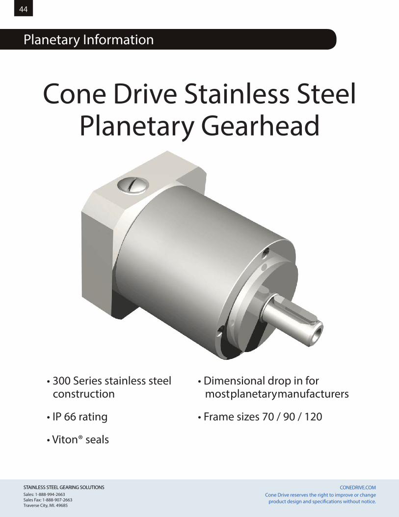
STAINLESS STEEL GEARING SOLUTIONS CONEDRIVE.COM STAINLESS STEEL GEARING SOLUTIONS CONEDRIVE.COM Sales: 1-888-994-2663Sales Fax: 1-888-907-2663Traverse City, MI. 49685
Cone Drive reserves the right to improve or change product design and specifications without notice.
44
Planetary Information
Cone Drive Stainless SteelPlanetary Gearhead
• 300 Series stainless steel construction
• IP 66 rating
• Viton® seals
• Dimensional drop in for most planetary manufacturers
• Frame sizes 70 / 90 / 120
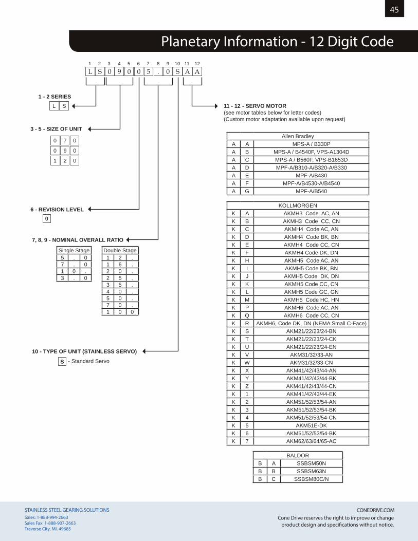
STAINLESS STEEL GEARING SOLUTIONS CONEDRIVE.COM STAINLESS STEEL GEARING SOLUTIONS CONEDRIVE.COM Sales: 1-888-994-2663Sales Fax: 1-888-907-2663Traverse City, MI. 49685
Cone Drive reserves the right to improve or change product design and specifications without notice.
45
Cone Drive Stainless SteelPlanetary Gearhead
Planetary Information - 12 Digit Code
L S 0 9 0 0 5 . 0 S A A1 2 3 4 5 6 7 8 9 10 11 12
1 - 2 SERIES
3 - 5 - SIZE OF UNIT
06 - REVISION LEVEL
S - Standard Servo
10 - TYPE OF UNIT (STAINLESS SERVO)
7, 8, 9 - NOMINAL OVERALL RATIO
Single Stage5 . 07 . 01 0 .3 . 0
Double Stage1 2 .1 6 .2 0 .2 5 .3 5 .4 0 .5 0 .7 0 .1 0 0
11 - 12 - SERVO MOTOR
0 7 0
L S
0 9 0
1 2 0
(see motor tables below for letter codes)(Custom motor adaptation available upon request)
Allen BradleyA A MPS-A / B330P A B MPS-A / B4540F, VPS-A1304DA C MPS-A / B560F, VPS-B1653DA D MPF-A/B310-A/B320-A/B330A E MPF-A/B430A F MPF-A/B4530-A/B4540A G MPF-A/B540
BALDORB A SSBSM50NB B SSBSM63NB C SSBSM80C/N
KOLLMORGENK A AKMH3 Code AC, AN K B AKMH3 Code CC, CNK C AKMH4 Code AC, ANK D AKMH4 Code BK, BNK E AKMH4 Code CC, CNK F AKMH4 Code DK, DNK H AKMH5 Code AC, ANK I AKMH5 Code BK, BN K J AKMH5 Code DK, DNK K AKMH5 Code CC, CNK L AKMH5 Code GC, GNK M AKMH5 Code HC, HNK P AKMH6 Code AC, ANK Q AKMH6 Code CC, CNK R AKMH6, Code DK, DN (NEMA Small C-Face) K S AKM21/22/23/24-BNK T AKM21/22/23/24-CKK U AKM21/22/23/24-ENK V AKM31/32/33-ANK W AKM31/32/33-CNK X AKM41/42/43/44-ANK Y AKM41/42/43/44-BKK Z AKM41/42/43/44-CNK 1 AKM41/42/43/44-EKK 2 AKM51/52/53/54-ANK 3 AKM51/52/53/54-BKK 4 AKM51/52/53/54-CNK 5 AKM51E-DKK 6 AKM51/52/53/54-BKK 7 AKM62/63/64/65-AC
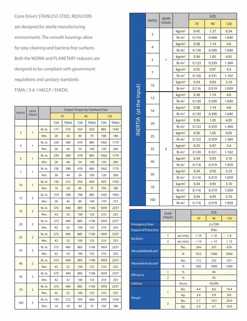
STAINLESS STEEL GEARING SOLUTIONS CONEDRIVE.COM STAINLESS STEEL GEARING SOLUTIONS CONEDRIVE.COM Sales: 1-888-994-2663Sales Fax: 1-888-907-2663Traverse City, MI. 49685
Cone Drive reserves the right to improve or change product design and specifications without notice.
46
GEAR STAGES
SIZE
70 90 120
Emergency Stop 2 x T2N
Degree of Protection IP66
Backlash1 arc-mins < 10 < 10 < 8
2 arc-mins < 14 < 14 < 12
Allowable Radial Load1lbs. 204 337 674
N 910 1500 3000
Allowable Axial Load1lbs. 112 225 337
N 500 1000 1500
Efficiency1 % 94
2 % 92
Lifetime Hours 30,000
Weight
1lbs. 4.4 8.6 19.4
kg. 2.0 3.9 8.8
2lbs. 5.1 10.3 24.0
kg. 2.3 4.7 10.9
RATIOS GEAR STAGES
Output Torque by Gearhead Size
70 90 120
T2N TMAX T2N TMAX T2N TMAX
3 1lb. in. 177 319 354 620 885 1593
Nm. 20 36 40 70 100 180
4 1lb. in. 230 389 478 885 1062 1770
Nm. 26 44 54 100 120 200
5 1lb. in. 230 389 478 885 1062 1770
Nm. 26 44 54 100 120 200
7 1lb. in. 230 389 478 885 1062 1770
Nm. 26 44 54 100 120 200
10 1lb. in. 142 212 354 664 929 1593
Nm. 16 24 40 75 105 180
12 2lb. in. 319 398 708 885 1505 1903
Nm. 36 45 80 100 170 215
16 2lb. in. 372 460 885 1106 1859 2257
Nm. 42 52 100 125 210 255
20 2lb. in. 372 460 885 1106 1859 2257
Nm. 42 52 100 125 210 255
25 2lb. in. 372 460 885 1106 1859 2257
Nm. 42 52 100 125 210 255
35 2lb. in. 372 460 885 1106 1859 2257
Nm. 42 52 100 125 210 255
40 2lb. in. 372 460 885 1106 1859 2257
Nm. 42 52 100 125 210 255
50 2lb. in. 372 460 885 1106 1859 2257
Nm. 42 52 100 125 210 255
70 2lb. in. 372 460 885 1106 1859 2257
Nm. 42 52 100 125 210 255
100 2lb. in. 142 212 354 664 929 1593
Nm. 16 24 40 75 105 180
Cone Drive’s STAINLESS STEEL REDUCERS
are designed for sterile manufacturing
environments. The smooth housings allow
for easy cleaning and bacteria free surfaces.
Both the WORM and PLANETARY reducers are
designed to be compliant with government
regulations and sanitary standards:
FSMA / 3-A / HACCP / EHEDG
RATIO GEAR STAGES
SIZE
70 90 120
3
1
kgcm2 0.45 1.37 6.54
lb-in2 0.154 0.468 1.640
4kgcm2 0.38 1.14 4.8
lb-in2 0.130 0.390 1.640
5kgcm2 0.36 1.05 4.05
lb-in2 0.123 0.359 1.384
7kgcm2 0.35 0.97 3.4
lb-in2 0.120 0.331 1.162
10kgcm2 0.34 0.93 3.10
lb-in2 0.116 0.319 1.059
12
2
kgcm2 0.38 1.14 4.8
lb-in2 0.130 0.390 1.640
16kgcm2 0.38 1.14 4.8
lb-in2 0.130 0.390 1.640
20kgcm2 0.36 1.05 4.05
lb-in2 0.123 0.359 1.384
25kgcm2 0.36 1.05 4.05
lb-in2 0.123 0.359 1.384
35kgcm2 0.35 0.97 3.4
lb-in2 0.120 0.331 1.162
40kgcm2 0.34 0.93 3.10
lb-in2 0.116 0.319 1.059
50kgcm2 0.34 0.93 3.10
lb-in2 0.116 0.319 1.059
70kgcm2 0.34 0.93 3.10
lb-in2 0.116 0.319 1.059
100kgcm2 0.34 0.93 3.10
lb-in2 0.116 0.319 1.059
INER
TIA
(at
the
inpu
t)
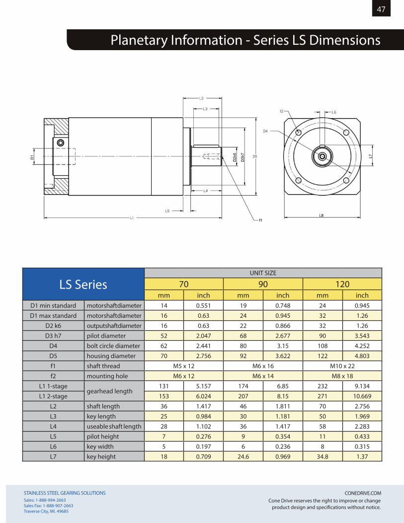
STAINLESS STEEL GEARING SOLUTIONS CONEDRIVE.COM STAINLESS STEEL GEARING SOLUTIONS CONEDRIVE.COM Sales: 1-888-994-2663Sales Fax: 1-888-907-2663Traverse City, MI. 49685
Cone Drive reserves the right to improve or change product design and specifications without notice.
47
LS SeriesUNIT SIZE
70 90 120mm inch mm inch mm inch
D1 min standard motor shaft diameter 14 0.551 19 0.748 24 0.945
D1 max standard motor shaft diameter 16 0.63 24 0.945 32 1.26
D2 k6 output shaft diameter 16 0.63 22 0.866 32 1.26
D3 h7 pilot diameter 52 2.047 68 2.677 90 3.543
D4 bolt circle diameter 62 2.441 80 3.15 108 4.252
D5 housing diameter 70 2.756 92 3.622 122 4.803
f1 shaft thread M5 x 12 M6 x 16 M10 x 22
f2 mounting hole M6 x 12 M6 x 14 M8 x 18
L1 1-stagegearhead length
131 5.157 174 6.85 232 9.134
L1 2-stage 153 6.024 207 8.15 271 10.669
L2 shaft length 36 1.417 46 1.811 70 2.756
L3 key length 25 0.984 30 1.181 50 1.969
L4 useable shaft length 28 1.102 36 1.417 58 2.283
L5 pilot height 7 0.276 9 0.354 11 0.433
L6 key width 5 0.197 6 0.236 8 0.315
L7 key height 18 0.709 24.6 0.969 34.8 1.37
Planetary Information - Series LS Dimensions
STAINLESS STEEL GEARING SOLUTIONS CONEDRIVE.COM STAINLESS STEEL GEARING SOLUTIONS CONEDRIVE.COM Sales: 1-888-994-2663Sales Fax: 1-888-907-2663Traverse City, MI. 49685
Cone Drive reserves the right to improve or change product design and specifications without notice.
48
Cone Drive double-enveloping worm gear speed reducers are used throughout Industry to provide smooth and quiet
speed reduction. When properly selected, applied and maintained, they will provide optimum performance.
IMPORTANT: In any applications of Cone Drive Products where breakage, damage, disconnection, any other malfunction of any drive train component, or excessive wear could result in personal
injury or property damage, a fail safe device capable of stopping and holding the load in the event of such an occurrence must be incorporated after the drive train.
1. Do not attempt to install or operate this reducer until all of these instructions are read and thoroughly understood. If you have any questions, please contact Cone Drive.2. The horsepower or output torque capacity of this reducer and the service factor (maximum allowable operating cycle) are stamped on the reducer nameplate. These values are not to be exceeded as overloading can result in reducer failure. Exceeding the rating and duty cycle will void the warranty. Please contact Cone Drive with any questions regarding rating and service factors.3. Each reducer is specifically arranged to operate at the input speed specified on the nameplate. If the input speed is not specified by the customer, it is set up for 1750 RPM and service factor 3. Do not operate the reducer at speeds or under service other than specified on the nameplate without contacting Cone Drive for specific instructions on oil level location and bearing settings.4. Do not alter the reducer without approval from Cone Drive.5. This reducer has moving mechanical components and connected electrical devices, operating under high voltage to achieve its intended purpose. Operation and repair should only be done by qualified personnel.6. Before servicing a speed reducer, the main electrical disconnect must be moved to and locked in the off-position. The person performing the work should post on that disconnect a warning to others not to turn on the power.
7. It is normal for the reducer to operate at a housing temperature of up to 200ºF. To prevent burns, proper guards or shields must be provided by the purchaser or user to prevent personnel from touching the reducer.8. Cone Drive products are furnished without guard covers. It is the responsibility of the purchase or user to provide guards for all exposed shafting, couplings, sprockets, sheaves, belts, chains, clutches, and any other moving parts in accordance with current local, state and federal requirements.9. Failure to follow the instructions contained in this bulletin may result in unit failure, property damage or personal injury.
THE FOLLOWING INFORMATION IS FOR YOUR PROTECTION. PLEASE READ CAREFULLY.
LUBRICATION, INSTALLATION, OPERATION & MAINTENANCE INSTRUCTIONS FORSTAINLESS STEEL CONE DRIVE SPEED REDUCERS
STAINLESS STEEL GEARING SOLUTIONS CONEDRIVE.COM STAINLESS STEEL GEARING SOLUTIONS CONEDRIVE.COM Sales: 1-888-994-2663Sales Fax: 1-888-907-2663Traverse City, MI. 49685
Cone Drive reserves the right to improve or change product design and specifications without notice.
49
LUBRICATION, INSTALLATION, OPERATION & MAINTENANCE INSTRUCTIONS FORSTAINLESS STEEL CONE DRIVE SPEED REDUCERS
START-UP1. After the reducer has been properly mounted, aligned and lubricated, it is ready for start-up.2. Make sure driven machine is clear of all obstructions and all safety guards and covers are in place, according to appropriate local, state and federal requirements. If possible, turn motor shaft by hand to confirm drive system is operating freely and in correct direction of rotation.
3. Jog motor to confirm proper rotation.
4. Operate reducer with minimum load for approximately 15 minutes (in both directions if applicable) to seat gears, bearings, and oil seals.
OPERATION1. All reducers require a few hours of “run-in” under load to achieve optimum efficiency. During this initial run-in the reducer will probably run warmer than normal and draw more current than after the run-in period. Reducers operating at a very low load or speed will take much longer to run-in and even if operated continuously at low load or speed may never achieve the efficiency that they would if operated at or near their catalog rating.
2. IMPORTANT: Normal reducer operating temperature measured at the oil sump area of the housing should not exceed 200º F. Excessive oil sump temperature is indicative of overloading, misalignment, or improper or marginal lubrication. Continuous operation of the reducer with the oil sump temperature above 200º F will result in premature breakdown of the oil and reduce the useful life of the reducer or result in premature failure.
MAINTENANCE1. All reducers and foundation bolts should be checked for tightness after three (3) months of service and annually thereafter.2. If a reducer is to be repaired, contact Cone Drive for detailedinstructions, drawings, parts lists, etc. If it is necessaryfield service is available.3. If a reducer is to be returned, contact Cone Drive for instructions and a return material authorization (CASE) number.
LUBRICATIONStainless steel reducers are factory filled with a high quality
foodgrade synthetic lubricant. They are “Lubricated for Life” and require no routine maintenance in service. In the event of a major overhaul involving strip-down and reassembly of the gear unit, refer to Table 1 for a list of approved lubricants. Lubricant quantities are given in Tables 2 & 3.If switching to the alternative lubricant, care should be taken tothoroughly flush out all of the old lubricant before filling with newlubricant. Mixing of different lubricants can result in degradedperformance or failure.
1. The speed reducer must be securely mounted to a rigidfoundation or base plate, flat enough to mate with the undersideof the reducer housing, so as to not create an unsanitary trap.2. Bolt the reducer to the foundation or mounting base using metric bolts that correspond to the threaded holes in the reducerhousing. Be sure to use a bolt in all available threaded mountingholes. Mount the reducer using bolts of minimum SAE Grade A2,Property Class 70, 304 Stainless Steel.3. Couplings, sheaves and sprockets should be mounted on thereducer shafts carefully. Do not pound or hammer them onto theshafts as this will damage bearings and oil seals. Angular and axial alignment of the output shaft to the rotating machine interface is critical to prevent premature output seal leaks.4. Sprockets and sheaves should be mounted as close to the reducer as possible and “V” belts and chains adjusted to the proper tension to keep bearing loading and shaft deflection to a minimum.Too much tension in belts and improper location of sheaves
and sprockets will lead to excessive chain pull, bearing wear andshaft deflection. For specific information on chain pull capacity,shaft stress and bearing life please contact Cone Drive.5. Before starting motor review motor rotation, reducer rotation and required direction of driven machine to ensure that the motor is wired for proper direction of rotation. In many instances a machine must run in one direction and failure to wire the motor properly can result in damage to the driven machine.6. Note: only use the approved lubricants if oil level top-off is necessary, as the factory filled PAG oil is not compatible with other oil types. Stainless steel speed reducers ship factoryfilled with oil and grease. For lubrication guidelines, see theApproved Lubricants and Lubrication Quantities tables inthe maintenance section.7. The speed reducer must be securely mounted to a rigid flatfoundation or base plate, either directly to the speed reducer or via the provided mounting feet. Note: stainless steel speed reducers are built for universal mounting, ready to mount in any position.
INSTALLATION
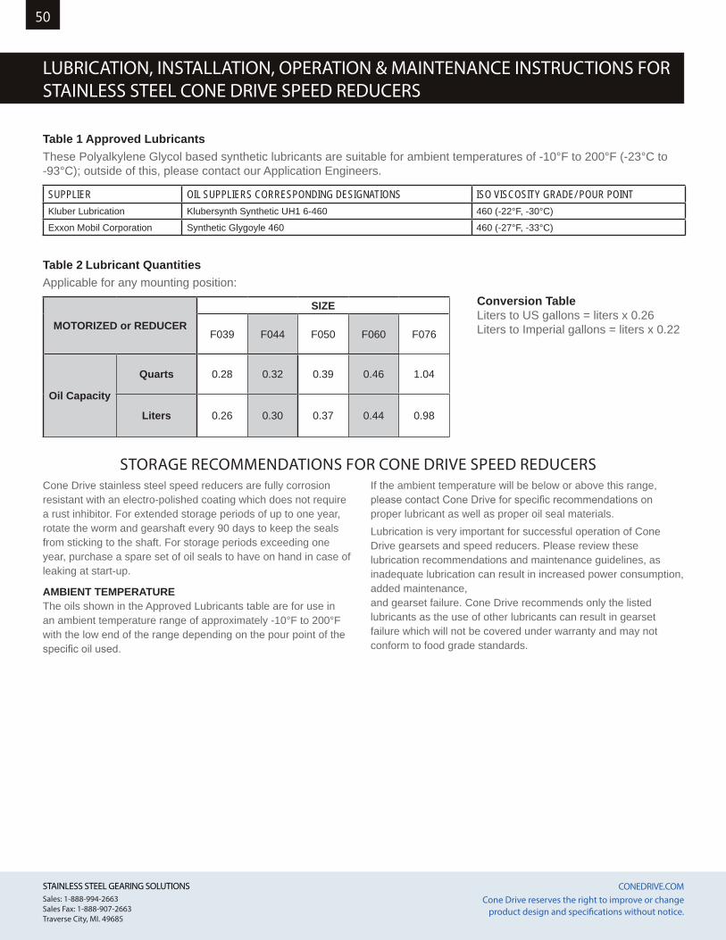
50
STAINLESS STEEL GEARING SOLUTIONS CONEDRIVE.COM STAINLESS STEEL GEARING SOLUTIONS CONEDRIVE.COM Sales: 1-888-994-2663Sales Fax: 1-888-907-2663Traverse City, MI. 49685
Sales: 1-888-994-2663Sales Fax: 1-888-907-2663Traverse City, MI. 49685
Cone Drive reserves the right to improve or change product design and specifications without notice.
Cone Drive reserves the right to improve or change product design and specifications without notice.
Table 1 Approved LubricantsThese Polyalkylene Glycol based synthetic lubricants are suitable for ambient temperatures of -10°F to 200°F (-23°C to -93°C); outside of this, please contact our Application Engineers.
SUPPLIER OIL SUPPLIERS CORRESPONDING DESIGNATIONS ISO VISCOSITY GRADE/ POUR POINTKluber Lubrication Klubersynth Synthetic UH1 6-460 460 (-22°F, -30°C)
Exxon Mobil Corporation Synthetic Glygoyle 460 460 (-27°F, -33°C)
Cone Drive stainless steel speed reducers are fully corrosion resistant with an electro-polished coating which does not require a rust inhibitor. For extended storage periods of up to one year, rotate the worm and gearshaft every 90 days to keep the seals from sticking to the shaft. For storage periods exceeding one year, purchase a spare set of oil seals to have on hand in case of leaking at start-up.
AMBIENT TEMPERATUREThe oils shown in the Approved Lubricants table are for use in an ambient temperature range of approximately -10°F to 200°F with the low end of the range depending on the pour point of the specific oil used.
If the ambient temperature will be below or above this range, please contact Cone Drive for specific recommendations on proper lubricant as well as proper oil seal materials.Lubrication is very important for successful operation of Cone Drive gearsets and speed reducers. Please review these lubrication recommendations and maintenance guidelines, as inadequate lubrication can result in increased power consumption, added maintenance,and gearset failure. Cone Drive recommends only the listedlubricants as the use of other lubricants can result in gearset failure which will not be covered under warranty and may not conform to food grade standards.
STORAGE RECOMMENDATIONS FOR CONE DRIVE SPEED REDUCERS
Table 2 Lubricant QuantitiesApplicable for any mounting position:
MOTORIZED or REDUCER
SIZE
F039 F044 F050 F060 F076
Oil Capacity
Quarts 0.28 0.32 0.39 0.46 1.04
Liters 0.26 0.30 0.37 0.44 0.98
Conversion TableLiters to US gallons = liters x 0.26Liters to Imperial gallons = liters x 0.22
LUBRICATION, INSTALLATION, OPERATION & MAINTENANCE INSTRUCTIONS FORSTAINLESS STEEL CONE DRIVE SPEED REDUCERS
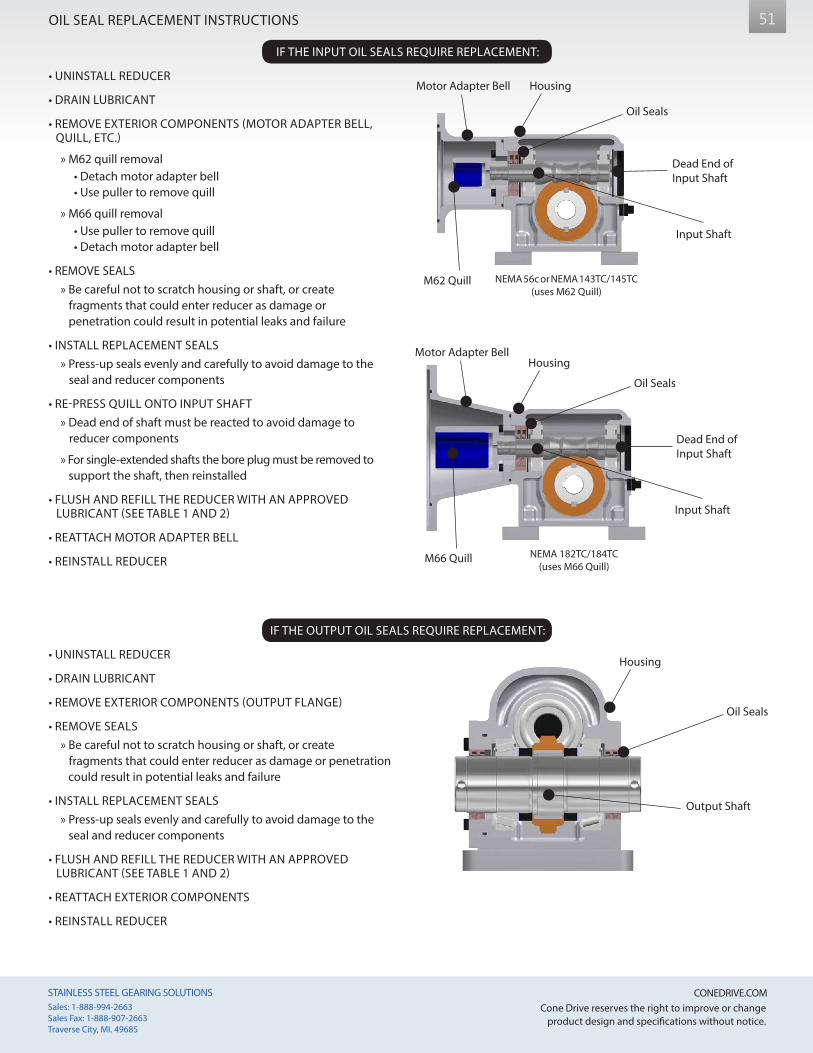
51
STAINLESS STEEL GEARING SOLUTIONS CONEDRIVE.COM STAINLESS STEEL GEARING SOLUTIONS CONEDRIVE.COM Sales: 1-888-994-2663Sales Fax: 1-888-907-2663Traverse City, MI. 49685
Sales: 1-888-994-2663Sales Fax: 1-888-907-2663Traverse City, MI. 49685
Cone Drive reserves the right to improve or change product design and specifications without notice.
Cone Drive reserves the right to improve or change product design and specifications without notice.
OIL SEAL REPLACEMENT INSTRUCTIONS
IF THE INPUT OIL SEALS REQUIRE REPLACEMENT:
• UNINSTALL REDUCER
• DRAIN LUBRICANT
• REMOVE EXTERIOR COMPONENTS (MOTOR ADAPTER BELL, QUILL, ETC.)
» M62 quill removal • Detach motor adapter bell • Use puller to remove quill
» M66 quill removal • Use puller to remove quill • Detach motor adapter bell
• REMOVE SEALS » Be careful not to scratch housing or shaft, or create fragments that could enter reducer as damage or penetration could result in potential leaks and failure
• INSTALL REPLACEMENT SEALS » Press-up seals evenly and carefully to avoid damage to the seal and reducer components
• RE-PRESS QUILL ONTO INPUT SHAFT » Dead end of shaft must be reacted to avoid damage to reducer components
» For single-extended shafts the bore plug must be removed to support the shaft, then reinstalled
• FLUSH AND REFILL THE REDUCER WITH AN APPROVED LUBRICANT (SEE TABLE 1 AND 2)
• REATTACH MOTOR ADAPTER BELL
• REINSTALL REDUCER
IF THE OUTPUT OIL SEALS REQUIRE REPLACEMENT:
• UNINSTALL REDUCER
• DRAIN LUBRICANT
• REMOVE EXTERIOR COMPONENTS (OUTPUT FLANGE)
• REMOVE SEALS » Be careful not to scratch housing or shaft, or create fragments that could enter reducer as damage or penetration could result in potential leaks and failure
• INSTALL REPLACEMENT SEALS » Press-up seals evenly and carefully to avoid damage to the seal and reducer components
• FLUSH AND REFILL THE REDUCER WITH AN APPROVED LUBRICANT (SEE TABLE 1 AND 2)
• REATTACH EXTERIOR COMPONENTS
• REINSTALL REDUCER
Oil Seals
Output Shaft
Housing
Motor Adapter Bell
M62 Quill
Input Shaft
Housing
Oil Seals
Dead End of Input Shaft
Motor Adapter Bell
M66 Quill
Input Shaft
Housing
Oil Seals
Dead End of Input Shaft
NEMA 56c or NEMA 143TC/145TC(uses M62 Quill)
NEMA 182TC/184TC(uses M66 Quill)

# 25297
Cone Drive Europe1 Redwood Crescent, Peel Park
East Kilbride G74 5PAUK
Cone Drive Operations, Inc.240 East 12th Street
Traverse City, Michigan 49684USA
H-FangA Cone Drive Brand
No. 20 Yungu RoadChangshou
Zhouzhuang Town, JiangyinJiangsu PR China 214424
T +1 888 994 2663E [email protected] www.conedrive.com
GLOBAL LOCATIONS
NORTH AMERICA | CHINA | EUROPE