Embed Size (px)
Citation preview
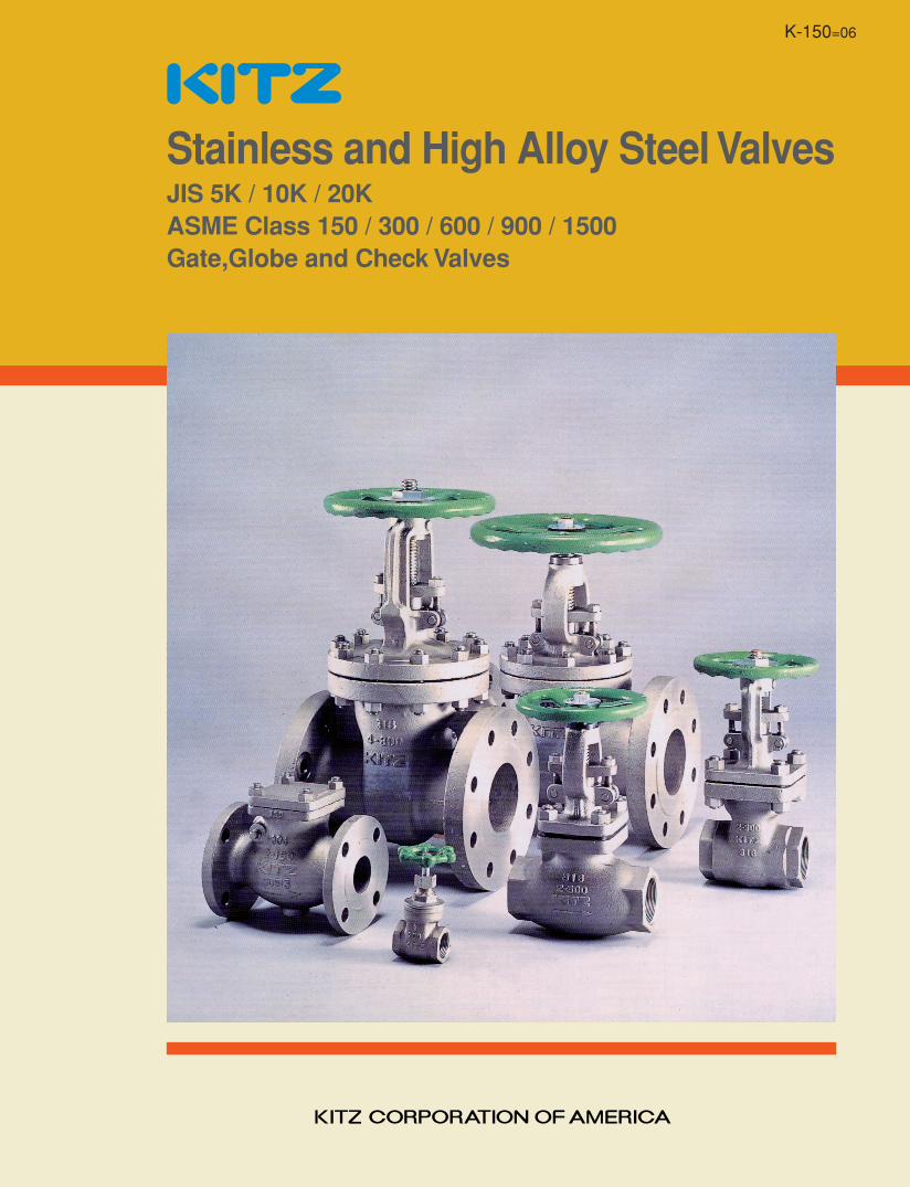
Stainless and High Alloy Steel ValvesJIS 5K / 10K / 20KASME Class 150 / 300 / 600 / 900 / 1500Gate,Globe and Check Valves
K-150=06
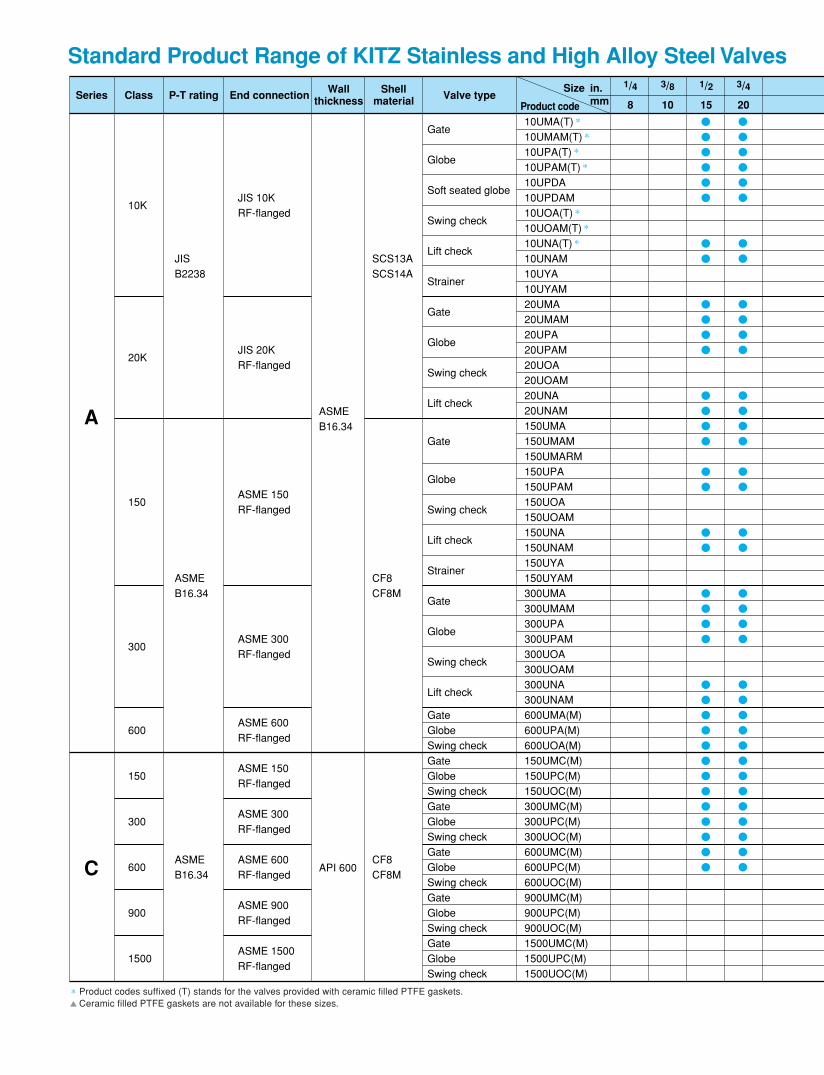
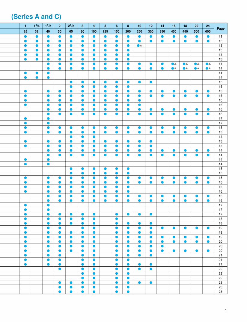
Standard Product Range of KITZ Stainless and High Alloy Steel Valves
* Product codes suffixed (T) stands for the valves provided with ceramic filled PTFE gaskets.� Ceramic filled PTFE gaskets are not available for these sizes.
10UMA(T) *10UMAM(T) *10UPA(T) *10UPAM(T) *10UPDA10UPDAM10UOA(T) *10UOAM(T) *10UNA(T) *10UNAM10UYA10UYAM20UMA20UMAM20UPA20UPAM20UOA20UOAM20UNA20UNAM150UMA150UMAM150UMARM150UPA150UPAM150UOA150UOAM150UNA150UNAM150UYA150UYAM300UMA300UMAM300UPA300UPAM300UOA300UOAM300UNA300UNAM600UMA(M)600UPA(M)600UOA(M)150UMC(M)150UPC(M)150UOC(M)300UMC(M)300UPC(M)300UOC(M)600UMC(M)600UPC(M)600UOC(M)900UMC(M)900UPC(M)900UOC(M)1500UMC(M)1500UPC(M)1500UOC(M)
�
�
�
�
�
�
�
�
�
�
�
�
�
�
�
�
�
�
�
�
�
�
�
�
�
�
�
�
�
�
�
�
�
�
�
�
�
�
�
�
�
�
�
�
�
�
�
�
�
�
�
�
�
�
�
�
�
�
�
�
�
�
�
�
�
�
�
�
�
�
�
�
�
�
10K
20K
150
300
600
150
300
600
900
1500
JISB2238
ASMEB16.34
ASMEB16.34
SCS13ASCS14A
CF8CF8M
CF8CF8M
Gate
Globe
Soft seated globe
Swing check
Lift check
Strainer
Gate
Globe
Swing check
Lift check
Gate
Globe
Swing check
Lift check
Strainer
Gate
Globe
Swing check
Lift check
GateGlobeSwing checkGateGlobeSwing checkGateGlobeSwing checkGateGlobeSwing checkGateGlobeSwing checkGateGlobeSwing check
JIS 10KRF-flanged
JIS 20KRF-flanged
ASME 150RF-flanged
ASME 300RF-flanged
ASME 600RF-flanged
ASME 150RF-flanged
ASME 300RF-flanged
ASME 600RF-flanged
ASME 900RF-flanged
ASME 1500RF-flanged
ASMEB16.34
API 600
Series Class P-T rating End connection Valve typeSize 1/4 3/8 1/2 3/4
8 10 15 20
in.mmProduct code
Wallthickness
Shellmaterial
A
C
(Series A and C)
1
�
�
�
�
�
�
�
�
�
�
�
�
�
�
�
�
�
�
�
�
�
�
�
�
�
�
�
�
�
�
�
�
�
�
�
�
�
�
�
�
�
�
�
�
�
�
�
�
�
�
�
�
�
�
�
�
�
�
�
�
�
�
�
�
�
�
�
�
�
�
�
�
�
�
�
�
�
�
�
�
�
�
�
�
�
�
�
�
�
�
�
�
�
�
�
�
�
�
�
�
�
�
�
�
�
�
�
�
�
�
�
�
�
�
�
�
�
�
�
�
�
�
�
�
�
�
�
�
�
�
�
�
�
�
�
�
�
�
�
�
�
�
�
�
�
�
�
�
�
�
�
�
�
�
�
�
�
�
�
�
�
�
�
�
�
�
�
�
�
�
�
�
�
�
�
�
�
�
�
�
�
�
�
�
�
�
�
�
�
�
�
�
�
�
�
�
�
�
�
�
�
�
�
�
�
�
�
�
�
�
�
�
�
�
�
�
�
�
�
�
�
�
�
�
�
�
�
�
�
�
�
�
�
�
�
�
�
�
�
�
�
�
�
�
�
�
�
�
�
�
�
�
�
�
�
�
�
�
�
�
�
�
�
�
�
�
�
�
�
�
�
�
�
�
�
�
�
�
�
�
�
�
�
�
�
�
�
�
�
�
�
�
�
�
�
�
�
�
�
�
�
�
�
�
�
�
�
�
�
�
�
�
�
�
�
�
�
�
�
�
�
�
�
�
�
�
�
�
�
�
�
�
�
�
�
�
�
�
�
�
�
�
�
�
�
�
�
�
�
�
�
�
�
�
�
�
�
�
�
�
�
�
�
��
�
�
�
�
�
�
�
�
�
�
�
�
�
�
�
�
�
�
�
�
�
�
�
�
�
�
�
�
�
�
�
�
�
�
�
�
�
�
�
�
�
�
�
�
�
�
�
�
�
�
�
�
�
�
�
�
�
�
�
�
�
�
�
�
�
�
�
�
�
�
�
�
�
�
�
�
�
�
�
�
�
�
�
�
�
��
��
�
�
�
�
�
�
�
�
�
�
�
�
�
�
�
�
�
�
��
��
�
�
�
�
�
�
�
�
�
�
�
�
�
�
�
�
�
�
��
��
�
�
�
�
�
�
�
�
�
�
�
�
�
�
�
�
�
�
��
��
�
�
�
�
�
�
�
�
�
�
�
�
�
�
�
�
131313131313141414141515151516161616171713131313131414141415151515161616161717171818191919202020212121222222232323
�
�
�
�
�
�
�
�
�
�
�
�
�
�
�
�
�
�
�
�
�
�
�
�
�
�
�
�
�
�
�
�
�
�
�
�
�
�
1 2 3 4 5 6 8 10 12 14 16 18 20 24Page
11/4 11/2 21/2
25 50 80 100 125 150 200 250 300 350 400 450 500 60032 40 65
3 4 5 6 721
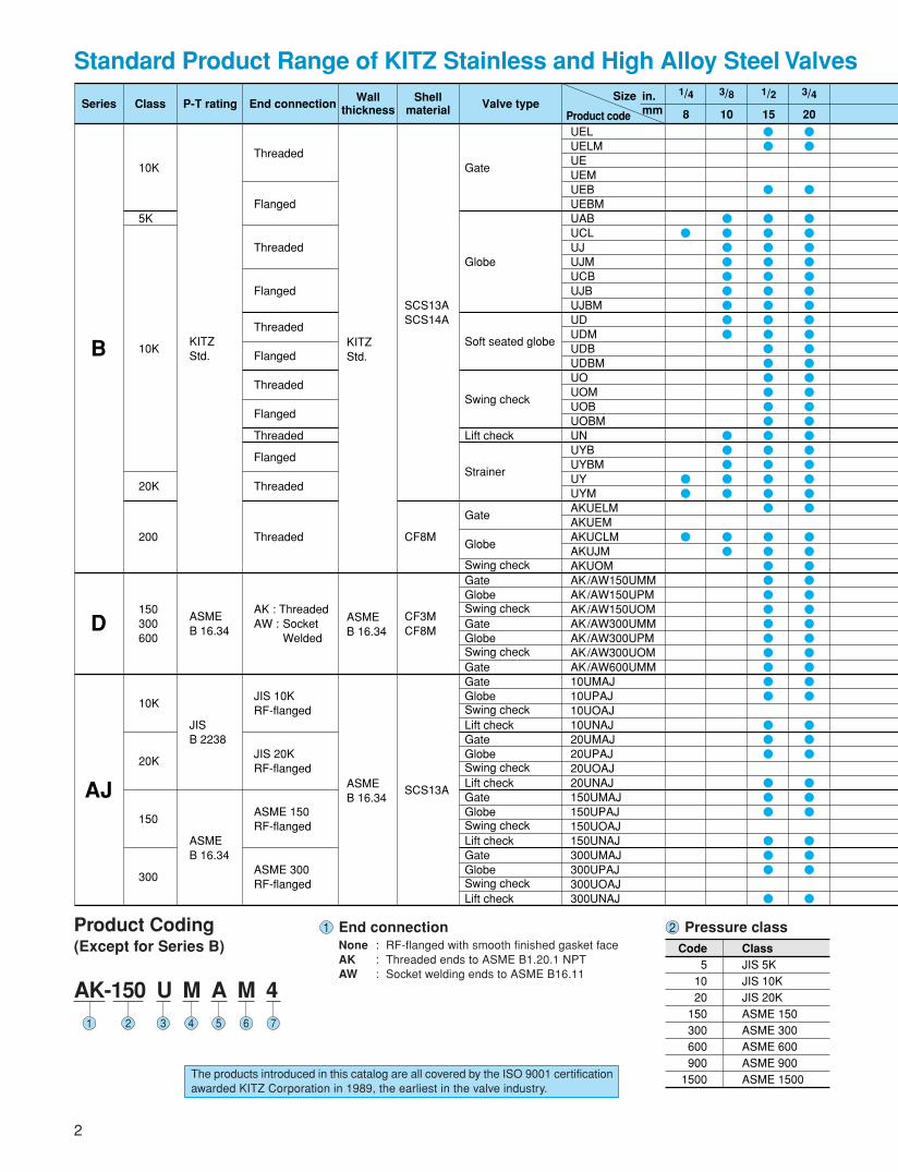
Standard Product Range of KITZ Stainless and High Alloy Steel Valves
UELUELMUEUEMUEBUEBMUABUCLUJUJMUCBUJBUJBMUDUDMUDBUDBMUOUOMUOBUOBMUNUYBUYBMUYUYMAKUELMAKUEMAKUCLMAKUJMAKUOMAK/AW150UMMAK/AW150UPMAK/AW150UOMAK/AW300UMMAK/AW300UPMAK/AW300UOMAK/AW600UMM10UMAJ10UPAJ10UOAJ10UNAJ20UMAJ20UPAJ20UOAJ20UNAJ150UMAJ150UPAJ150UOAJ150UNAJ300UMAJ300UPAJ300UOAJ300UNAJ
�
��
�
���������
�����
��
��
�
���������������������
������������
���
���
���
�
��
�
���������������������
������������
���
���
���
�
10K
5K
10K
20K
200
150300600
10K
20K
150
300
KITZStd.
ASMEB 16.34
JISB 2238
ASMEB 16.34
SCS13ASCS14A
CF8M
CF3MCF8M
SCS13A
Gate
Globe
Soft seated globe
Swing check
Lift check
Strainer
Gate
Globe
Swing checkGateGlobeSwing checkGateGlobeSwing checkGateGateGlobeSwing checkLift checkGateGlobeSwing checkLift checkGateGlobeSwing checkLift checkGateGlobeSwing checkLift check
Threaded
Flanged
Threaded
Flanged
Threaded
Flanged
Threaded
Flanged
Threaded
Flanged
Threaded
Threaded
AK : ThreadedAW : Socket
Welded
JIS 10KRF-flanged
JIS 20KRF-flanged
ASME 150RF-flanged
ASME 300RF-flanged
KITZStd.
ASMEB 16.34
ASMEB 16.34
Series Class P-T rating End connection Valve typeSize 1/4 3/8 1/2 3/4
8 10 15 20
in.mmProduct code
Wallthickness
Shellmaterial
AJ
D
B
Product Coding(Except for Series B)
AK-150 U M A M 4
2
1 End connectionNone : RF-flanged with smooth finished gasket faceAK : Threaded ends to ASME B1.20.1 NPTAW : Socket welding ends to ASME B16.11
The products introduced in this catalog are all covered by the ISO 9001 certificationawarded KITZ Corporation in 1989, the earliest in the valve industry.
2 Pressure classCode
51020
150300600900
1500
ClassJIS 5KJIS 10KJIS 20KASME 150ASME 300ASME 600ASME 900ASME 1500
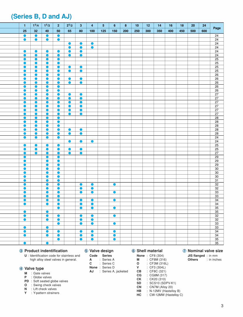
(Series B, D and AJ)
��
�����������������������
����������������
���
���
�
��
�����������������������
����������������
���
���
�
��
�����������������������
�����������������
���
���
����
��
��
������
��
�
��
����
��
��
������
��
�
��
���
���
���
���
��
�
���
���
���
���
�
�
�
�
�
�
���
242424242424252525252626262626272727272727282828282824242525272929293030303132323333343435353232333334343535
��
�����������������������
���
1 2 3 4 5 6 8 10 12 14 16 18 20 24Page
11/4 11/2 21/2
25 50 80 100 125 150 200 250 300 350 400 450 500 60032 40 65
3
3 Product indentificationU : Identification code for stainless and
high alloy steel valves in general.
4 Valve typeM : Gate valvesP : Globe valvesPD : Soft seated globe valvesO : Swing check valvesN : Lift check valvesY : Y-pattern strainers
5 Valve designCode SeriesA : Series AC : Series CNone : Series DAJ : Series A, jacketed
6 Shell materialNone : CF8 (304)M : CF8M (316)O : CF3M (316L)V : CF3 (304L)CB : CF8C (321)CG : CG8M (317)CK : CK20 (310)SD : SCS10 (SDPV-K1)CN : CN7M (Alloy 20)HB : N-12MV (Hastelloy B)HC : CW-12MW (Hastelloy C)
7 Nominal valve sizeJIS flanged : in mmOthers : in inches
Corrosion Resistant Service withKITZ Stainless and High Alloy Steel Valves
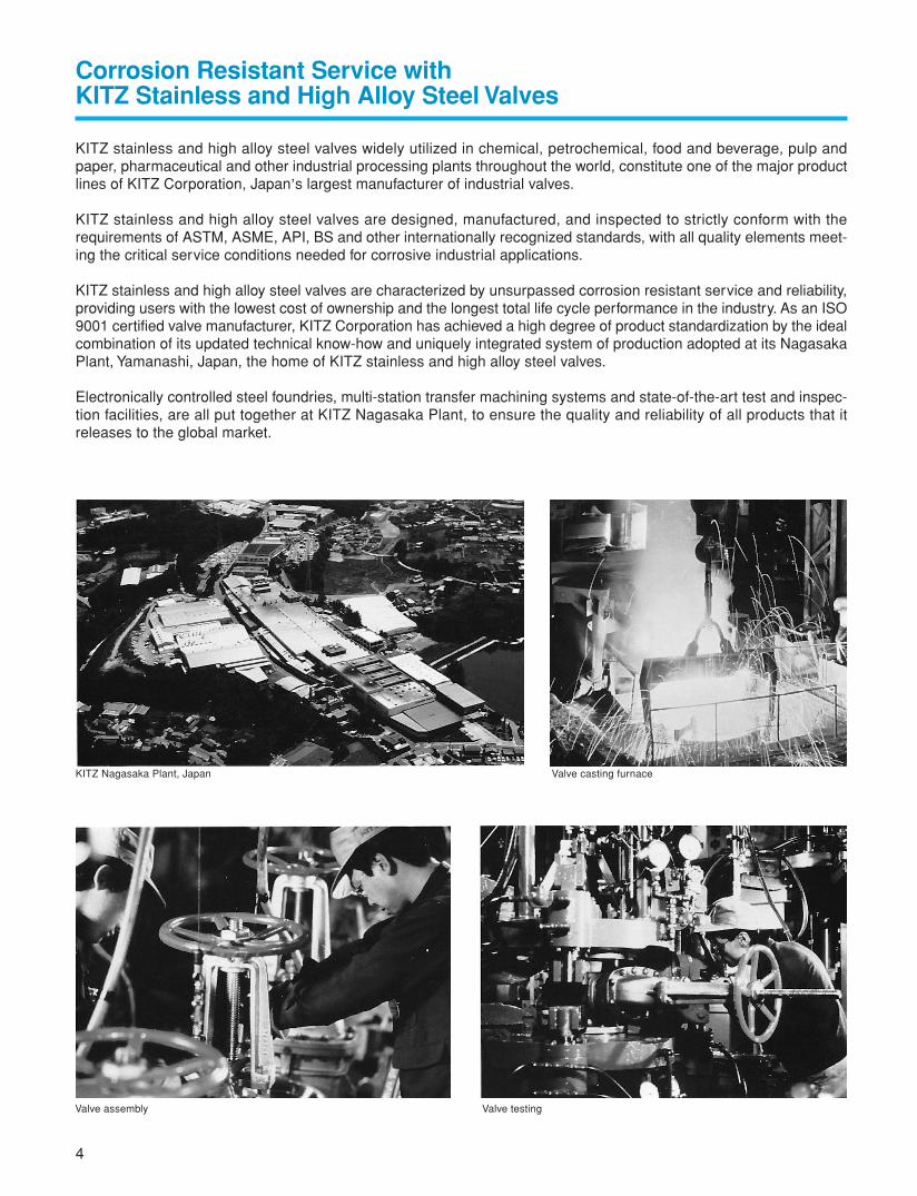
KITZ stainless and high alloy steel valves widely utilized in chemical, petrochemical, food and beverage, pulp andpaper, pharmaceutical and other industrial processing plants throughout the world, constitute one of the major productlines of KITZ Corporation, Japan,s largest manufacturer of industrial valves.
KITZ stainless and high alloy steel valves are designed, manufactured, and inspected to strictly conform with therequirements of ASTM, ASME, API, BS and other internationally recognized standards, with all quality elements meet-ing the critical service conditions needed for corrosive industrial applications.
KITZ stainless and high alloy steel valves are characterized by unsurpassed corrosion resistant service and reliability,providing users with the lowest cost of ownership and the longest total life cycle performance in the industry. As an ISO9001 certified valve manufacturer, KITZ Corporation has achieved a high degree of product standardization by the idealcombination of its updated technical know-how and uniquely integrated system of production adopted at its NagasakaPlant, Yamanashi, Japan, the home of KITZ stainless and high alloy steel valves.
Electronically controlled steel foundries, multi-station transfer machining systems and state-of-the-art test and inspec-tion facilities, are all put together at KITZ Nagasaka Plant, to ensure the quality and reliability of all products that itreleases to the global market.
KITZ Nagasaka Plant, Japan
Valve testingValve assembly
Valve casting furnace
4
Stainless Steel (CF8)
Carbon Steel (WCB)
Ductile Iron (A395)
Cast Iron (A126-B)
800
900
(N / mm2)
700
600
500
Tens
ile S
tren
gth
Temperature (°C)
400
300
200
100
0–200 –100 0 100 200 300 400 500
Stainless Steel(CF8)
Carbon Steel (WCB)
Ductile Iron (A395)
Cast Iron (A126-B)
140
180
(Charpy value : J)
100
60
50
Impa
ct V
alue
Temperature (°C)
40
30
20
10
0–200 –100 0 100 200 300 400 500
5
Features of Austenitic Stainless Steel as Valve Material
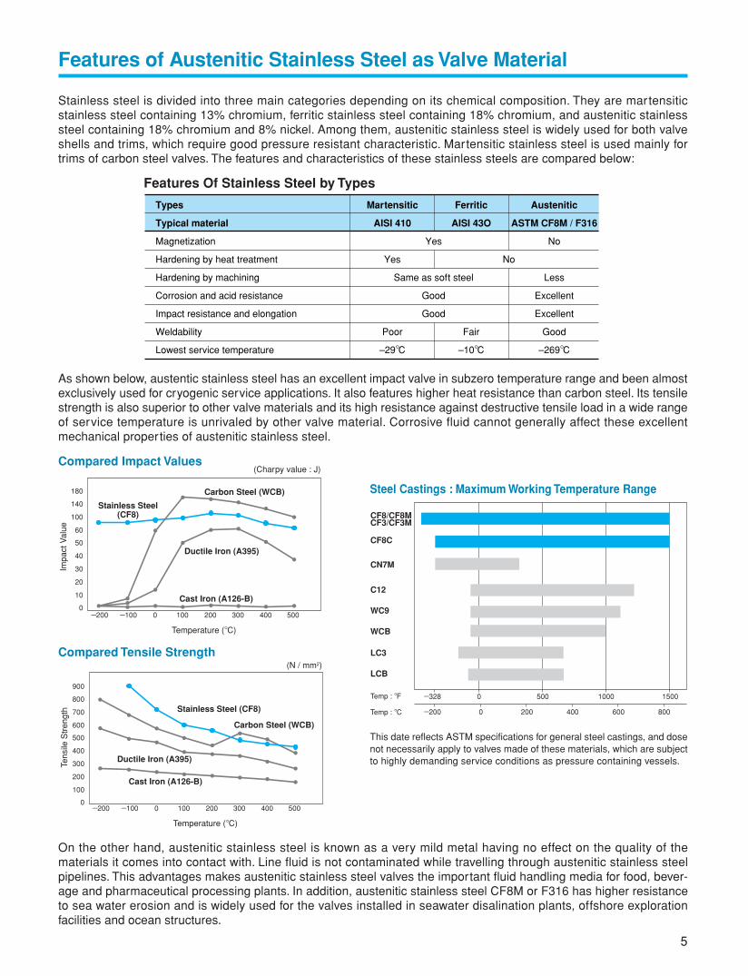
This date reflects ASTM specifications for general steel castings, and dosenot necessarily apply to valves made of these materials, which are subjectto highly demanding service conditions as pressure containing vessels.
Stainless steel is divided into three main categories depending on its chemical composition. They are martensiticstainless steel containing 13% chromium, ferritic stainless steel containing 18% chromium, and austenitic stainlesssteel containing 18% chromium and 8% nickel. Among them, austenitic stainless steel is widely used for both valveshells and trims, which require good pressure resistant characteristic. Martensitic stainless steel is used mainly fortrims of carbon steel valves. The features and characteristics of these stainless steels are compared below:
Features Of Stainless Steel by Types
Types
Typical material
Magnetization
Hardening by heat treatment
Hardening by machining
Corrosion and acid resistance
Impact resistance and elongation
Weldability
Lowest service temperature
Martensitic
AISI 410
Yes
Poor
–29°C
Yes
Same as soft steel
Good
Good
No
Ferritic
AISI 43O
Fair
–10°C
Austenitic
ASTM CF8M / F316
No
Less
Excellent
Excellent
Good
–269°C
As shown below, austentic stainless steel has an excellent impact valve in subzero temperature range and been almostexclusively used for cryogenic service applications. It also features higher heat resistance than carbon steel. Its tensilestrength is also superior to other valve materials and its high resistance against destructive tensile load in a wide rangeof service temperature is unrivaled by other valve material. Corrosive fluid cannot generally affect these excellentmechanical properties of austenitic stainless steel.
Compared Impact Values
Compared Tensile Strength
On the other hand, austenitic stainless steel is known as a very mild metal having no effect on the quality of thematerials it comes into contact with. Line fluid is not contaminated while travelling through austenitic stainless steelpipelines. This advantages makes austenitic stainless steel valves the important fluid handling media for food, bever-age and pharmaceutical processing plants. In addition, austenitic stainless steel CF8M or F316 has higher resistanceto sea water erosion and is widely used for the valves installed in seawater disalination plants, offshore explorationfacilities and ocean structures.
Steel Castings : Maximum Working Temperature Range
CF8/CF8MCF3/CF3M
CF8C
CN7M
C12
WC9
WCB
LC3
LCB
Temp : °F
Temp : °C
150010005000–328
–200 0 200 400 600 800
Bonnet Gasket Materials
* Actual pressure-temperature rating in service depends on the materials of gland packing and gasket chosen for valves.
6
A
Series Class
10K
20K
150 / 300 / 600
150 / 300 / 600 / 900 / 1500
5K
10K
20K
200
150 / 300 / 600
10K
20K
150 / 300
Wall thichness
ASME B16.34
API 600
JIS B 2011
KITZ Std.
ASME B16.34
ASME B16.34
Pressure - temperatureratings*
JIS B2238
ASME B16.34
ASME B16.34
0.49MPa (5kgf/cm2)150°C0.98MPa (10kgf/cm2)180°C1.96MPa (20kgf/cm2)180°C
KITZ Std.
ASME B16.34
JIS B2238
ASME B16.34
Face-to facedimensions
JIS B2002
ASME B16.10
ASME B16.10
JIS B 2011
KITZ Std.
KITZ Std.
KITZ Std.
End connectiondimensions
JIS B2238 10K flanged
JIS B2238 20K flanged
ASME B16.5 flanged
ASME B16.5 flanged
JIS B0203 threaded
JIS B2238 10K flanged
ASME B1.20.1 threaded
ASME B1.20.1 threaded
ASME B16.11 socket
JIS B2238 10K flanged
JIS B2238 20K flanged
ASME B16.5 flanged
C
B
D
AJ
General Design Specifications
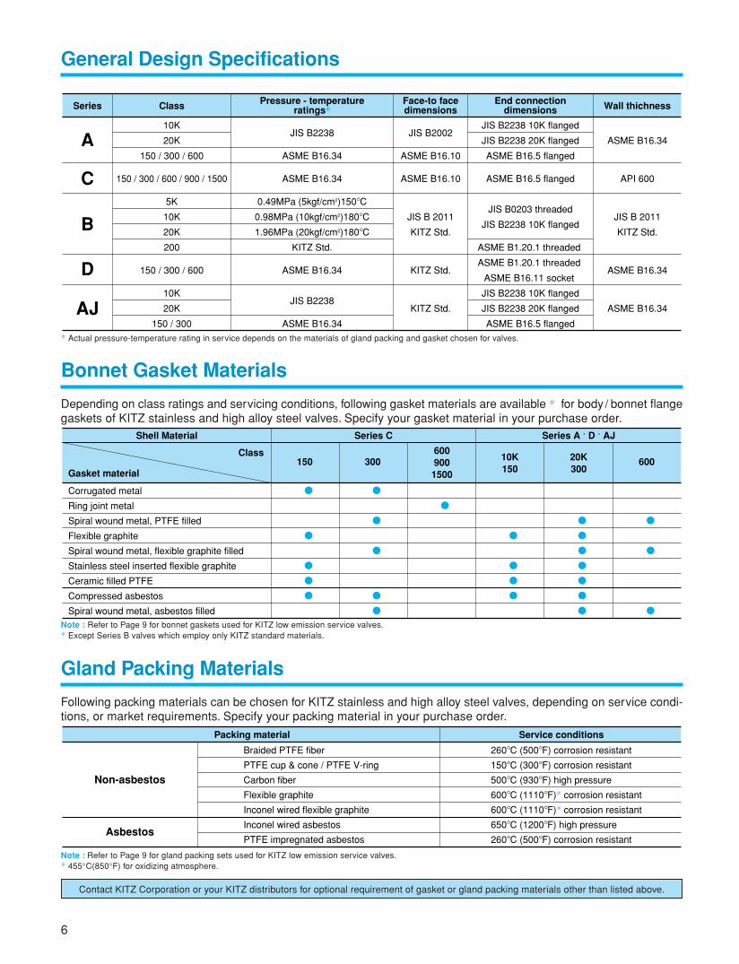
Depending on class ratings and servicing conditions, following gasket materials are available * for body / bonnet flangegaskets of KITZ stainless and high alloy steel valves. Specify your gasket material in your purchase order.
Class
Corrugated metal
Ring joint metal
Spiral wound metal, PTFE filled
Flexible graphite
Spiral wound metal, flexible graphite filled
Stainless steel inserted flexible graphite
Ceramic filled PTFE
Compressed asbestos
Spiral wound metal, asbestos filled
Gasket material
�
�
�
�
�
�
�
�
�
�
�
�
�
�
�
�
�
�
�
�
�
�
�
�
�
150 300 600600900
1500
10K150
20K300
Series C Series A · D · AJShell Material
Note : Refer to Page 9 for bonnet gaskets used for KITZ low emission service valves.* Except Series B valves which employ only KITZ standard materials.
Gland Packing Materials
Following packing materials can be chosen for KITZ stainless and high alloy steel valves, depending on service condi-tions, or market requirements. Specify your packing material in your purchase order.
Note : Refer to Page 9 for gland packing sets used for KITZ low emission service valves.* 455°C(850°F) for oxidizing atmosphere.
Braided PTFE fiber
PTFE cup & cone / PTFE V-ring
Carbon fiber
Flexible graphite
Inconel wired flexible graphite
Inconel wired asbestos
PTFE impregnated asbestos
Non-asbestos
Asbestos
260°C (500°F) corrosion resistant
150°C (300°F) corrosion resistant
500°C (930°F) high pressure
600°C (1110°F)* corrosion resistant
600°C (1110°F)* corrosion resistant
650°C (1200°F) high pressure
260°C (500°F) corrosion resistant
Packing material Service conditions
Contact KITZ Corporation or your KITZ distributors for optional requirement of gasket or gland packing materials other than listed above.
7
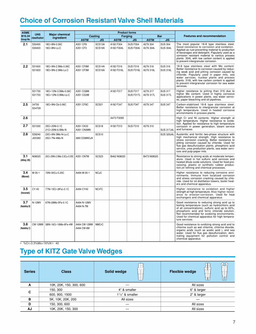
Choice of Corrosion Resistant Valve Shell Materials
ASMEB16.34Group No.
UNSclassification
Major chemicalingredient
Product formsCasting
ASTM JISForging Bar Features and recommendation
ASTM JIS ASTM JIS
The most popular 18-8 type stainless steel. Good resistance to corrosion and oxidation.Applied as rust-preventing material to production of beverages and detergent. Papularly used as a corrosion resistant material to various process plants. 304L with low carbon content is applied to prevent intergranular corrosion.
18-8 type stainless steel with Mo content. Better resistance to corrosion caused by reduc-ing weak acid and pitting corrosion caused by chloride. Popularly used in paper mils, sea water services, nuclear plants and process plants. 316L with low carbon content is applied to prevent intergranular corrosion for sea water services.
Higher resistance to pitting than 316 due to higher Mo content. Used in highly corrosive applications in power plants, sea water servic-es, paper bleaching and oil pipelines.
Carbon-stabilized 18-8 type stainless steel. Better resistance to intergranular corrosion at high temperature. Used in heated corrosive environments in process plants.
High Cr and Ni contents. Higher strength at high temperature. Higher resistance to oxida-tion. Applied for resistance to high temperature corrosion in power generation, steam service and furnaces.
Austenitic and ferritic two-phase structure with high mechanical strength. High resistance to stress corrosion cracking. Better resistance to pitting corrosion caused by chloride. Used for flue gas desulfurization plants, phosphoric acid service, urea production plants, sea water serv-ices and pulp-paper mils.
Resistance to strong acids at moderate temper-ature. Used in hot sulfuric acid services and heated dilute oxide solutions. Used for food pro-cessing, plastic or synthetic rubber produc-tion,oil refining and chemical processes.
Higher resistance to reducing corrosive envi-ronments. Immune from localized corrosion and stress corrosion cracking caused by chlo-ride. Used for oil distillation towers, boiler heat-ers and chemical apparatus.
Higher resistance to oxidation and higher strength at high temperature. Also higher resist-ance to erosion-corrosion. Used for heat exchangers and chemical apparatus.
Good resistance to reducing strong acid up to boiling temperature (such as hydrochloric acid of all concentrations), sulfuric acid up to 60%, phosphoric acid and ferric chloride solution. Not recommended for oxidizing environments. Used for chemical apparatus for high tempera-ture services.
Good resistance to oxidizing strong acid and to chlorine such as wet chlorine, chlorine dioxide, organic acids (such as acetic acid ), and sea water. Used for flue gas desulfurization, deni-trating equipment for pollution control and chemical apparatus.
2.1 S30400S30403
18Cr-8Ni-0.06C18Cr-8Ni-Lo.C
A351 CF8A351 CF3
A182 F304A182 F304L
SCS13ASCS19A
SUS F304SUS F304L
A276 304A276 304L
SUS 304SUS 304L
2.2 S31600S31603
18Cr-9Ni-2.5Mo-0.06C18Cr-9Ni-2.5Mo-Lo.C
A351 CF8MA351 CF3M
A182 F316A182 F316L
SCS14ASCS16A
SUS F316SUS F316L
A276 316A276 316L
SUS 316SUS 316L
S31700S31703
18Cr-12Ni-3.5Mo-0.06C18Cr-12Ni-3.5Mo-Lo.C
A351 CG8MA351 CG3M
A182 F317 SUS F317SUS F317L
A276 317A276 317L
SUS 317SUS 317L
2.5 34700S34709
18Cr-9Ni-Cb-0.06C A351 CF8C A182 F347SCS21 SUS F347 A276 347 SUS 347
2.6 A473 F309S
2.7 S31000 25Cr-20Ni-0.1C21Cr-25Ni-6.5Mo-N
A351 CK20A351 CN3MN
A182 F310SCS18 SUS F310 A276 310SUS 317J4L
2.8 S39240J93380
23Cr-6Ni-3Mo-N-Lo.C25Cr-7Ni-4Mo-N A890 CD3MWCuN※
SCS10※ SUS 329J4L
3.1(Alloy 20)
N08020 20Cr-29Ni-2.5Mo-3.5Cu-0.05C A351 CN7M B462 N08020SCS23 B473 N08020
3.4(Monel)
M-35-1 70Ni-30Cu-0.25C A494 M-35-1 NCuC
3.5(Inconel)
CY-40 77Ni-15Cr-(8Fe)-0.1C A494 CY40 NCrFC
3.7(Hastelloy B)
N-12MV 67Ni-28Mo-5Fe-0.1C A494 N-12MVA494 N-7M
3.8(Hastelloy C)
CW-12MW 58Ni-16Cr-16Mo-6Fe-4W A494 CW-12MWA494 CW-6M
NMCrC
Type of KITZ Gate Valve Wedges
* All KITZ stainless and high alloy steel valves are integrally seated. For Class 150, 300 and 600 of Series C, however, renewable seats are optionally available in caseof 2” and larger sizes.
A
C
BDAJ
Series
10K, 20K, 150, 300, 600
150, 300
600, 900, 1500
5K, 10K, 20K, 200
150, 300, 600
10K, 20K, 150, 300
Class
—
4” & smaller
11/2” & smaller
All sizes
—
—
Solid wedge
All sizes
6” & larger
2” & larger
—
All sizes
All sizes
Flexibie wedge
※%Cr+3.3%Mo+16%N≧ 40
8
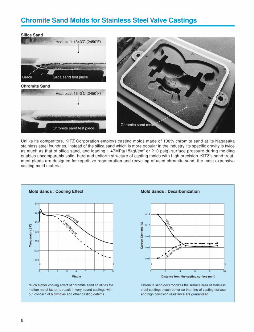
Chromite Sand Molds for Stainless Steel Valve Castings
Silica Sand
Chromite Sand
Unlike its competitors, KITZ Corporation employs casting molds made of 100% chromite sand at its Nagasakastainless steel foundries, instead of the silica sand which is more popular in the industry. Its specific gravity is twiceas much as that of silica sand, and loading 1.47MPa(15kgf/cm2 or 210 psig) surface pressure during moldingenables uncomparably solid, hard and uniform structure of casting molds with high precision. KITZ’s sand treat-ment plants are designed for repetitive regeneration and recycling of used chromite sand, the most expensivecasting mold material.
1600
1500
1400
1300
1200
1100
1000
0
0.04
0.06
0.12
0.10
0.08
0 2 4 6 8 101 2 3 4 5 6 7 8
Minute
Tem
per
atu
re (
° C)
Distance from the casting surface (mm)
Car
bo
n C
on
ten
t (%
)
Silica sandChromite
sand
Silicasand
Chromitesand
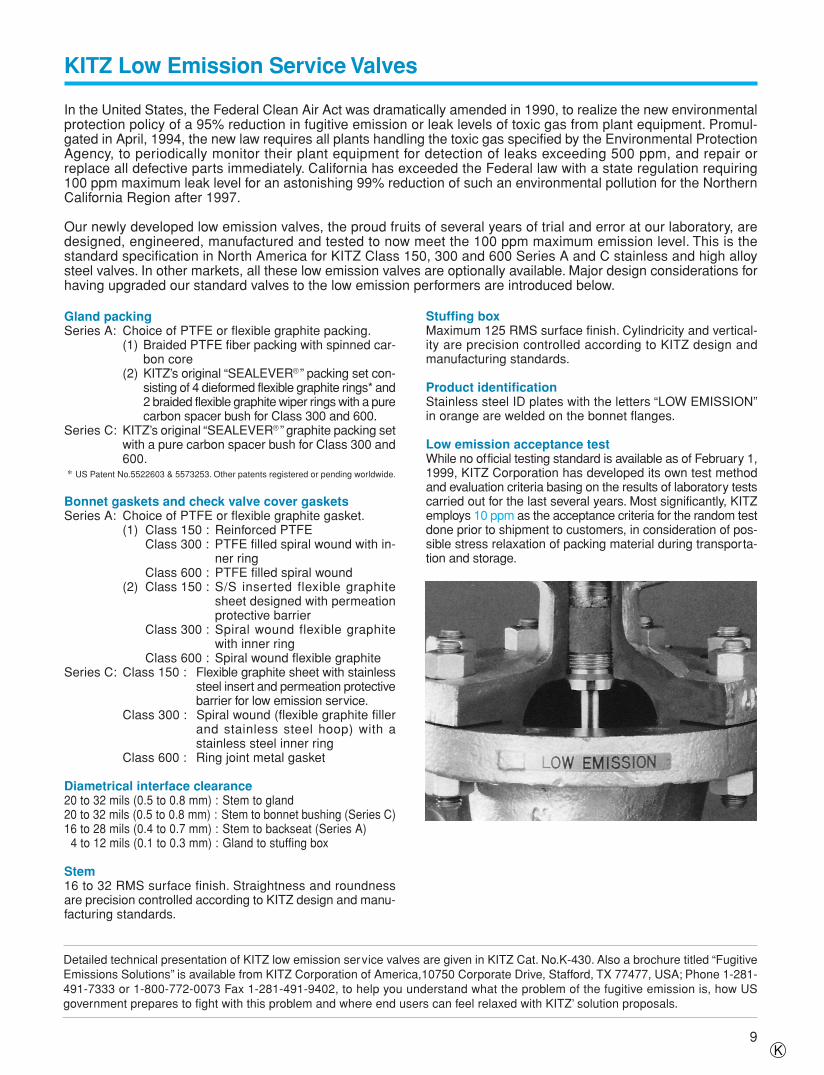
Mold Sands : Cooling Effect Mold Sands : Decarbonization
Much higher cooling effect of chromite sand solidifies themolten metal faster to result in very sound castings with-out concern of blowholes and other casting defects.
Chromite sand decarbonizes the surface area of stainlesssteel castings much better so that fine of casting surfaceand high corrosion resistance are guaranteed.
9
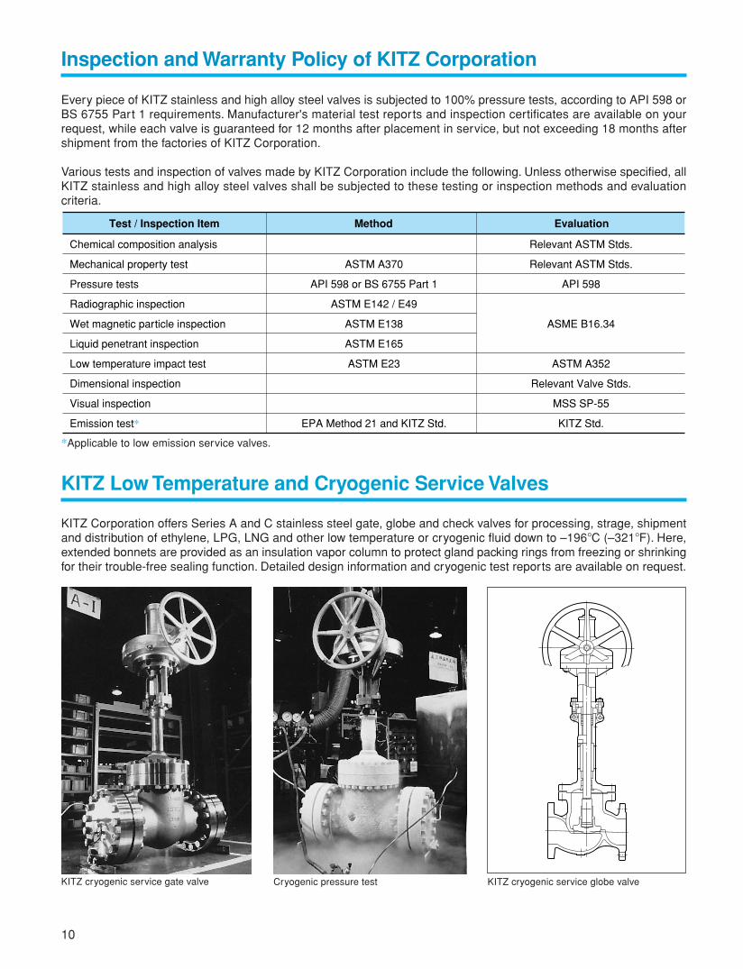
KITZ Low Emission Service Valves
In the United States, the Federal Clean Air Act was dramatically amended in 1990, to realize the new environmentalprotection policy of a 95% reduction in fugitive emission or leak levels of toxic gas from plant equipment. Promul-gated in April, 1994, the new law requires all plants handling the toxic gas specified by the Environmental ProtectionAgency, to periodically monitor their plant equipment for detection of leaks exceeding 500 ppm, and repair orreplace all defective parts immediately. California has exceeded the Federal law with a state regulation requiring100 ppm maximum leak level for an astonishing 99% reduction of such an environmental pollution for the NorthernCalifornia Region after 1997.
Our newly developed low emission valves, the proud fruits of several years of trial and error at our laboratory, aredesigned, engineered, manufactured and tested to now meet the 100 ppm maximum emission level. This is thestandard specification in North America for KITZ Class 150, 300 and 600 Series A and C stainless and high alloysteel valves. In other markets, all these low emission valves are optionally available. Major design considerations forhaving upgraded our standard valves to the low emission performers are introduced below.
Gland packingSeries A: Choice of PTFE or flexible graphite packing.
(1) Braided PTFE fiber packing with spinned car-bon core
(2) KITZ’s original “SEALEVER® ” packing set con-sisting of 4 dieformed flexible graphite rings* and2 braided flexible graphite wiper rings with a purecarbon spacer bush for Class 300 and 600.
Series C: KITZ’s original “SEALEVER® ” graphite packing setwith a pure carbon spacer bush for Class 300 and600.
* US Patent No.5522603 & 5573253. Other patents registered or pending worldwide.
Bonnet gaskets and check valve cover gasketsSeries A: Choice of PTFE or flexible graphite gasket.
(1) Class 150 : Reinforced PTFEClass 300 : PTFE filled spiral wound with in-
ner ringClass 600 : PTFE filled spiral wound
(2) Class 150 : S/S inserted flexible graphitesheet designed with permeationprotective barrier
Class 300 : Spiral wound flexible graphitewith inner ring
Class 600 : Spiral wound flexible graphiteSeries C: Class 150 : Flexible graphite sheet with stainless
steel insert and permeation protectivebarrier for low emission service.
Class 300 : Spiral wound (flexible graphite fillerand stainless steel hoop) with astainless steel inner ring
Class 600 : Ring joint metal gasket
Diametrical interface clearance20 to 32 mils (0.5 to 0.8 mm) : Stem to gland20 to 32 mils (0.5 to 0.8 mm) : Stem to bonnet bushing (Series C)16 to 28 mils (0.4 to 0.7 mm) : Stem to backseat (Series A) 4 to 12 mils (0.1 to 0.3 mm) : Gland to stuffing box
Stem16 to 32 RMS surface finish. Straightness and roundnessare precision controlled according to KITZ design and manu-facturing standards.
Stuffing boxMaximum 125 RMS surface finish. Cylindricity and vertical-ity are precision controlled according to KITZ design andmanufacturing standards.
Product identificationStainless steel ID plates with the letters “LOW EMISSION”in orange are welded on the bonnet flanges.
Low emission acceptance testWhile no official testing standard is available as of February 1,1999, KITZ Corporation has developed its own test methodand evaluation criteria basing on the results of laboratory testscarried out for the last several years. Most significantly, KITZemploys 10 ppm as the acceptance criteria for the random testdone prior to shipment to customers, in consideration of pos-sible stress relaxation of packing material during transporta-tion and storage.
Detailed technical presentation of KITZ low emission service valves are given in KITZ Cat. No.K-430. Also a brochure titled “FugitiveEmissions Solutions” is available from KITZ Corporation of America,10750 Corporate Drive, Stafford, TX 77477, USA; Phone 1-281-491-7333 or 1-800-772-0073 Fax 1-281-491-9402, to help you understand what the problem of the fugitive emission is, how USgovernment prepares to fight with this problem and where end users can feel relaxed with KITZ’ solution proposals.
K
10
Inspection and Warranty Policy of KITZ Corporation
Every piece of KITZ stainless and high alloy steel valves is subjected to 100% pressure tests, according to API 598 orBS 6755 Part 1 requirements. Manufacturer's material test reports and inspection certificates are available on yourrequest, while each valve is guaranteed for 12 months after placement in service, but not exceeding 18 months aftershipment from the factories of KITZ Corporation.
Various tests and inspection of valves made by KITZ Corporation include the following. Unless otherwise specified, allKITZ stainless and high alloy steel valves shall be subjected to these testing or inspection methods and evaluationcriteria.
Chemical composition analysis
Mechanical property test
Pressure tests
Radiographic inspection
Wet magnetic particle inspection
Liquid penetrant inspection
Low temperature impact test
Dimensional inspection
Visual inspection
Emission test*
ASTM A370
API 598 or BS 6755 Part 1
ASTM E142 / E49
ASTM E138
ASTM E165
ASTM E23
EPA Method 21 and KITZ Std.
Relevant ASTM Stds.
Relevant ASTM Stds.
API 598
ASME B16.34
ASTM A352
Relevant Valve Stds.
MSS SP-55
KITZ Std.
Test / Inspection Item Method Evaluation
*Applicable to low emission service valves.
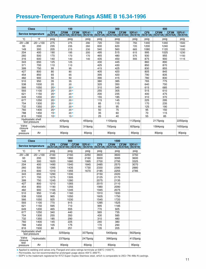
KITZ Low Temperature and Cryogenic Service Valves
KITZ Corporation offers Series A and C stainless steel gate, globe and check valves for processing, strage, shipmentand distribution of ethylene, LPG, LNG and other low temperature or cryogenic fluid down to –196°C (–321°F). Here,extended bonnets are provided as an insulation vapor column to protect gland packing rings from freezing or shrinkingfor their trouble-free sealing function. Detailed design information and cryogenic test reports are available on request.
KITZ cryogenic service gate valve Cryogenic pressure test KITZ cryogenic service globe valve
11
Pressure-Temperature Ratings ASME B 16.34-1996
� Applied to welding end valves only. Flanged end valve ratings terminate at 538°C (1000°F).
* Permissible, but not recommended for prolonged usage above 454°C (850°F).
**SDPV is the trademark registered for KITZ Super Duplex Stainless steel, which is comparable to 25Cr-7Ni-4Mo-N castings.
°C-29~+38
93149204260316343371399427454482510538566593621649677704732760788816
°F-20~+100
20030040050060065070075080085090095010001050110011501200125013001350140014501500
psig
27523520519017014012511095806550352020202020202020201510
�
�
�
�
�
�
�
�
�
�
�
�
�
�
�
�
�
�
�
�
psig
27523521519517014012511095806550352020202020202020202015
psig
290260230200170140
psig
750720665615575555
psig
150014401330123011501115
Class 150
Service temperature CF8(SCS13A)
CF8M(SCS14A)
SDPV-K1**(SCS10)
SDPV-K1**(SCS10)
SDPV-K1**(SCS10)
CF3M*(SCS16A)
psig
7206005404954654354304254154053953903803203102552001551158560503525
psig
72062056051548045044543042542042041538535034530523518514511595756040
300CF8
(SCS13A)CF8M
(SCS14A)CF3M*
(SCS16A)
psig
144012001080995930875860850830805790780765640615515400310225170125957055
psig
144012401120102595590089087085584583583077570068561047537029523519015011585
600CF8
(SCS13A)CF8M
(SCS14A)CF3M
(SCS16A)
Hydrostatic shelltest pressure
Hydrostatic
Air
303psig
425psig
80psig
792psig
1100psig
80psig
319psig
450psig
80psig
825psig
1125psig
80psig
1650psig
2250psig
80psig
1584psig
2175psig
80psig
Valveclosure
test pressure
°C-29~+38
93149204260316343371399427454482510538566593621649677704732760788816
°F-20~+100
20030040050060065070075080085090095010001050110011501200125013001350140014501500
psig
216018001620149013951310129012751245121011901165114596592577059546534025518514510580
psig
216018601680154014351355133013051280126512551245116010501030915710555440350290225175251
psig
225021601995184517301670
Class 900
Service temperature CF8(SCS13A)
CF8M(SCS14A)
CF3M*(SCS16A)
SDPV-K1**(SCS10)
SDPV-K1**(SCS10)
psig
3600300027002485233021852150212520752015198019451910160515451285995770565430310240170135
psig
36003095279525702390225522202170213521102090207519301750172015251185925735585480380290205
psig
375036003325307028802785
1500CF8
(SCS13A)CF8M
(SCS14A)CF3M*
(SCS16A)
Hydrostatic shelltest pressure
Hydrostatic
Air
2376psig
3250psig
80psig
2475psig
3375psig
80psig
3960psig
5400psig
80psig
4125psig
5625psig
80psig
Valveclosure
test pressure
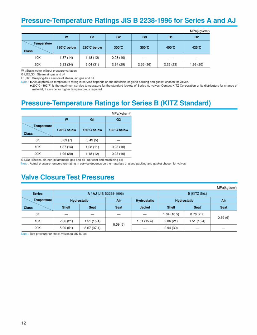
Note : Test pressure for check valves to JIS B2003
Pressure-Temperature Ratings JIS B 2238-1996 for Series A and AJ
W : Static water without pressure variationG1,G2,G3 : Steam,air,gas and oilH1,H2 : Creeping-free service of steam, air, gas and oilNote : Actual pressure-temperature rating in service depends on the materials of gland packing and gasket chosen for valves.
200°C (392°F) is the maximum service temperature for the standard jackets of Series AJ valves. Contact KITZ Corporation or its distributors for change ofmaterial, if service for higher temperature is required.
10K
20K
1.37 (14)
3.33 (34)
Class120°C below
W
1.18 (12)
3.04 (31)
220°C below
G1
0.98 (10)
2.84 (29)
300°C
G2
—
2.55 (26)
350°C
G3
—
2.26 (23)
400°C
H1
—
1.96 (20)
425°C
H2
Temperature
MPa(kgf/cm2)
Pressure-Temperature Ratings for Series B (KITZ Standard)
5K
10K
20K
0.69 (7)
1.37 (14)
1.96 (20)
Class120°C below
W
0.49 (5)
1.08 (11)
1.18 (12)
150°C below
G1
—
0.98 (10)
0.98 (10)
180°C below
G2
Temperature
MPa(kgf/cm2)
G1,G2 : Steam, air, non-inflammable gas and oil (lubricant and machining oil)Note : Actual pressure-temperature rating in service depends on the materials of gland packing and gasket chosen for valves.
Valve Closure Test Pressures
Series
5K
10K
20K
—
2.06 (21)
5.00 (51)
—
1.51 (15.4)
3.67 (37.4)
—
1.51 (15.4)
—
1.04 (10.5)
2.06 (21)
2.94 (30)
0.76 (7.7)
1.51 (15.4)
—
0.59 (6)
—
—
0.59 (6)
Class Shell Seat
Hydrostatic Hydrostatic
Seat Jacket
AirTemperature
A / AJ (JIS B2238-1996)
Shell Seat
Hydrostatic
Seat
Air
B (KITZ Std.)
MPa(kgf/cm2)
12
A
13
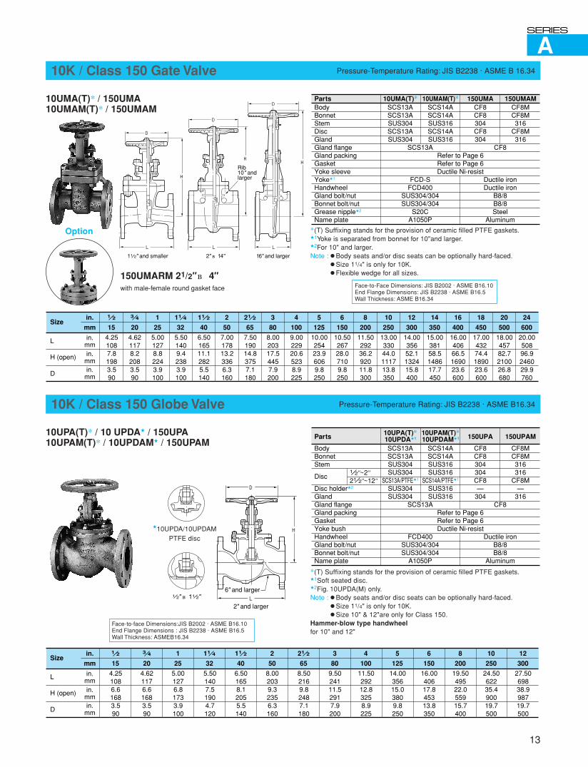
Face-to-Face Dimensions: JIS B2002 · ASME B16.10End Flange Dimensions: JIS B2238 · ASME B16.5Wall Thickness: ASME B16.34
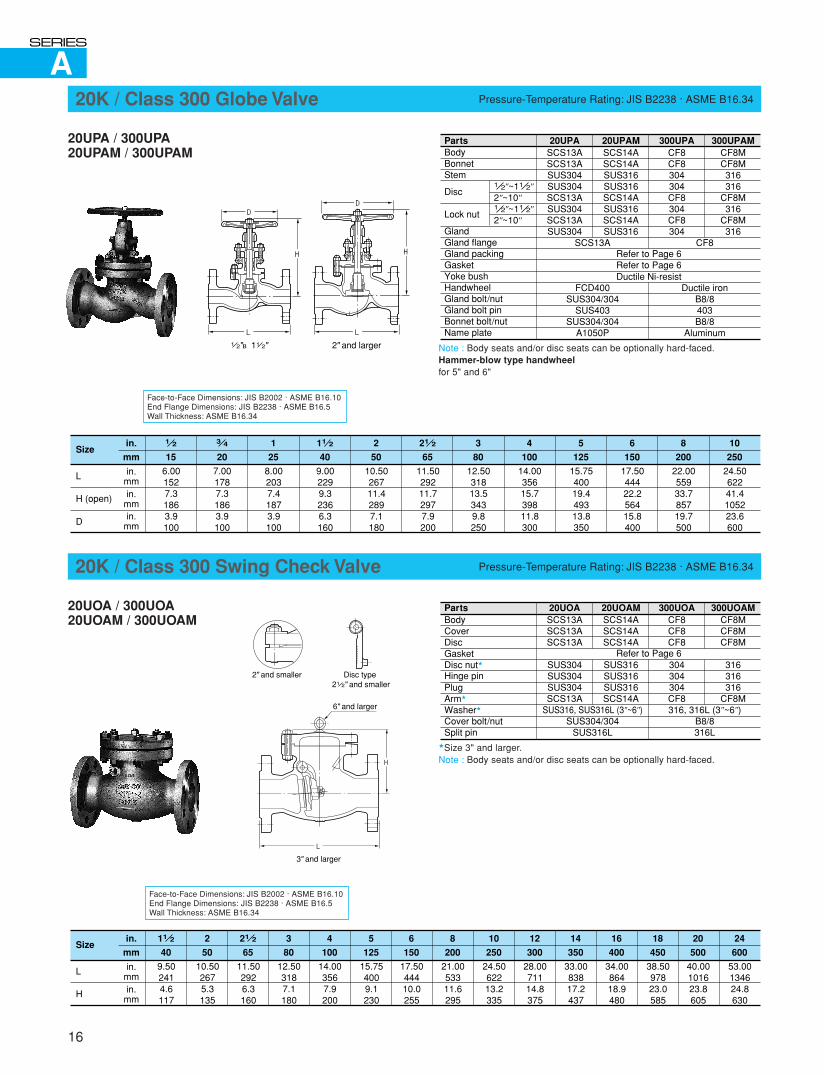
10K / Class 150 Gate Valve Pressure-Temperature Rating: JIS B2238 · ASME B 16.34
10UMA(T)* / 150UMA10UMAM(T)* / 150UMAM
PartsBodyBonnetStemDiscGlandGland flangeGland packingGasketYoke sleeveYoke�1
HandwheelGland bolt/nutBonnet bolt/nutGrease nipple�2
Name plate
10UMA(T)*SCS13ASCS13ASUS304SCS13ASUS304
10UMAM(T)*SCS14ASCS14ASUS316SCS14ASUS316
SCS13A
FCD-SFCD400
SUS304/304SUS304/304
S20CA1050P
150UMACF8CF8304CF8304
150UMAMCF8MCF8M316
CF8M316
CF8
Ductile ironDuctile iron
B8/8B8/8Steel
Aluminum
Refer to Page 6Refer to Page 6Ductile Ni-resist
1 2
15
in.
mm
in.mm
4.251087.81983.590
in.mmin.
mm
Size
L
H (open)
D
3 4
20
11 2
40
11 4
32
21 2
65
4.621178.22083.590
5.501409.42383.9100
6.5016511.12825.5140
7.5019014.83757.1180
1
25
5.001278.82243.9100
2
50
7.0017813.23366.3160
3
80
8.0020317.54457.9200
4
100
9.0022920.65238.9225
5
125
10.0025423.96069.8250
6
150
10.5026728.07109.8250
8
200
11.5029236.292011.8300
10
250
13.0033044.0111713.8350
12
300
14.0035652.1132415.8400
14
350
15.0038158.5148617.7450
16
400
16.0040666.5169023.6600
18
450
17.0043274.4189023.6600
20
500
18.0045782.7210026.8680
24
600
20.0050896.9246029.9760
*(T) Suffixing stands for the provision of ceramic filled PTFE gaskets.�1Yoke is separated from bonnet for 10"and larger.�2For 10" and larger.Note : � Body seats and/or disc seats can be optionally hard-faced.
� Size 11/4" is only for 10K.� Flexible wedge for all sizes.150UMARM 21/2"~ 4"
with male-female round gasket face
Option
D
L
H
D
D
L L
HH
Rib10" andlarger
11 2" and smaller 2" ~14" 16" and larger
Face-to-face Dimensions:JIS B2002 · ASME B16.10End Flange Dimensions : JIS B2238 · ASME B16.5Wall Thickness: ASMEB16.34
10K / Class 150 Globe Valve Pressure-Temperature Rating: JIS B2238 · ASME B16.34
10UPA(T)* / 10 UPDA� / 150UPA10UPAM(T)* / 10UPDAM� / 150UPAM
*(T) Suffixing stands for the provision of ceramic filled PTFE gaskets.�1Soft seated disc.�2Fig. 10UPDA(M) only.Note : � Body seats and/or disc seats can be optionally hard-faced.
� Size 11/4" is only for 10K.� Size 10" & 12"are only for Class 150.
Hammer-blow type handwheelfor 10" and 12"
✩Hammer-blow type handwheel.
D
L
H
1 2" ~11 2" 6" and larger
2" and larger
�10UPDA/10UPDAMPTFE disc
Parts
BodyBonnetStem
Disc
Disc holder�2
GlandGland flangeGland packingGasketYoke bushHandwheelGland bolt/nutBonnet bolt/nutName plate
1 2"~2"21 2"~12"
10UPA(T)*10UPDA�1
SCS13ASCS13ASUS304SUS304
SCS13A/PTFE�1
SUS304SUS304
10UPAM(T)*10UPDAM�1
SCS14ASCS14ASUS316SUS316
SCS14A/PTFE�1
SUS316SUS316
SCS13A
FCD400SUS304/304SUS304/304
A1050P
150UPA
CF8CF8304304CF8—
304
150UPAM
CF8MCF8M316316
CF8M—
316CF8
Ductile ironB8/8B8/8
Aluminum
Refer to Page 6Refer to Page 6Ductile Ni-resist
1 2
15
in.
mm
in.mm
4.251086.61683.590
in.mmin.
mm
Size
L
H (open)
D
3 4
20
11 2
40
11 4
32
21 2
65
4.621176.61683.590
5.501407.51904.7120
6.501658.12055.5140
8.502169.82487.1180
1
25
5.001276.81733.9100
2
50
8.002039.32356.3160
3
80
9.5024111.52917.9200
4
100
11.5029212.83258.9225
5
125
14.0035615.03809.8250
6
150
16.0040617.845313.8350
8
200
19.5049522.055915.7400
10
250
24.5062235.490019.7500
12
300
27.5069838.998719.7500
A
14
Face-to-Face Dimensions: JIS B2002 · ASME B16.10End Flange Dimensions: JIS B2238 · ASME B16.5Wall Thickness: ASME B16.34
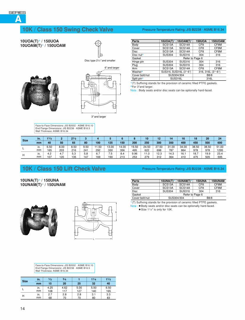
10K / Class 150 Swing Check Valve Pressure-Temperature Rating: JIS B2238 · ASME B16.34
10UOA(T)* / 150UOA10UOAM(T)* / 150UOAM
*(T) Suffixing stands for the provision of ceramic filled PTFE gaskets.�For 3"and larger.Note : Body seats and/or disc seats can be optionally hard-faced.
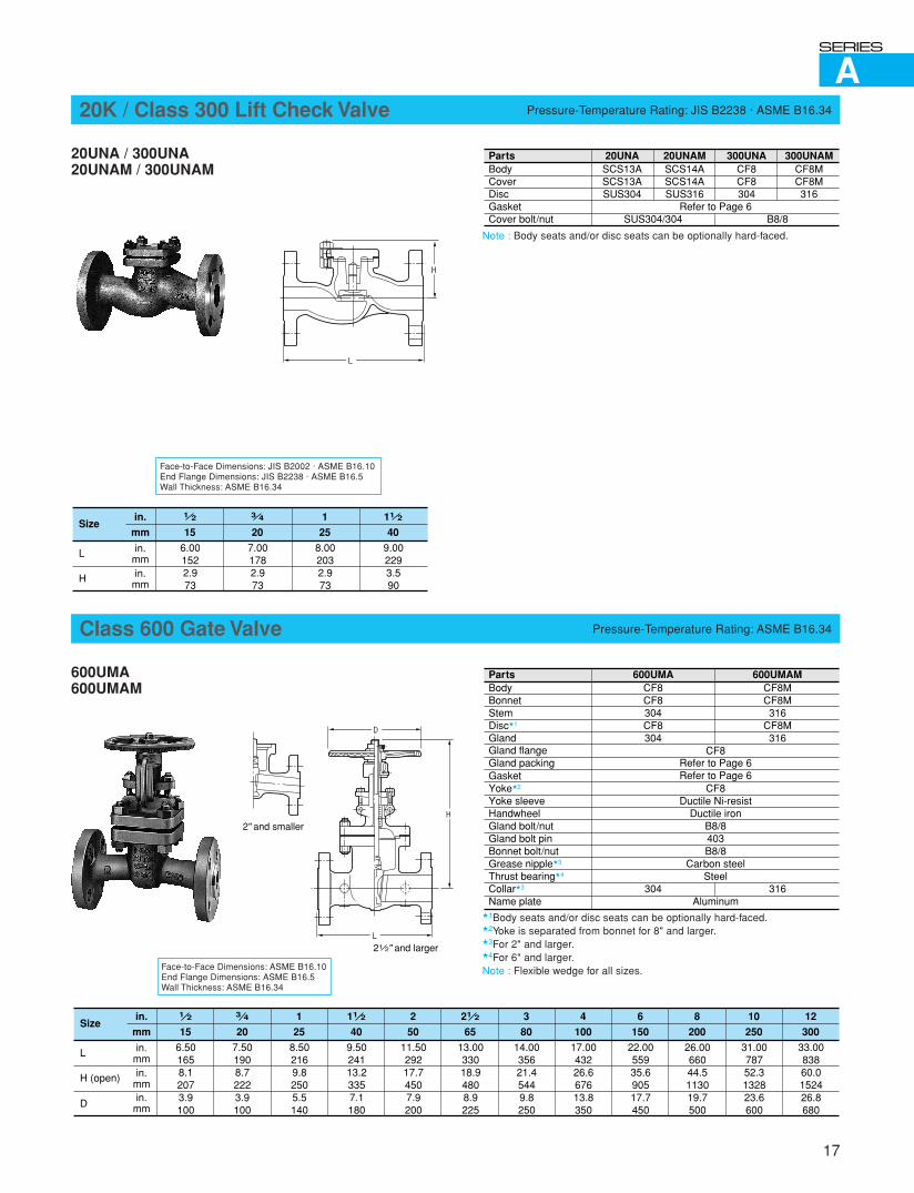
10K / Class 150 Lift Check Valve Pressure-Temperature Rating: JIS B2238 · ASME B16.34
10UNA(T)* / 150UNA10UNAM(T)* / 150UNAM
PartsBodyCoverDiscDisc nut�
GasketHinge pinPlugArmWasher�
Cover bolt/nutSplit pin�
10UOA(T)*SCS13ASCS13ASCS13ASUS304
SUS304SUS304SCS13A
10UOAM(T)*SCS14ASCS14ASCS14ASUS316
SUS316SUS316SCS14A
SUS316, SUS316L (3"~6")SUS304/304
SUS316L
150UOACF8CF8CF8304
304304CF8
150UOAMCF8MCF8MCF8M316
316316
CF8M316, 316L (3"~6")
B8/8316L
Refer to Page 6
PartsBodyCoverDiscGasketCover bolt/nut
10UNA(T)*SCS13ASCS13ASUS304
10UNAM(T)*SCS14ASCS14ASUS316
SUS304/304
150UNACF8CF8304
150UNAMCF8MCF8M316
B8/8Refer to Page 6
in.
mm
in.mmin.
mm
Size
L
H
11 2
40
6.501653.383
11 4
32
5.501403.180
3 4
20
4.621172.870
1 2
15
4.251082.768
1
25
5.001272.870
L
H
Disc type 21 2" and smaller
6" and larger
3" and larger
Face-to-Face Dimensions: JIS B2002 · ASME B16.10End Flange Dimensions: JIS B2238 · ASME B16.5Wall Thickness: ASME B16.34
*(T) Suffixing stands for the provision of ceramic filled PTFE gaskets.Note : � Body seats and/or disc seats can be optionally hard-faced.
� Size 11/4" is only for 10K.
L
H
in.
mm
in.mmin.
mm
Size
L
H
11 2
40
21 2
65
6.501654.2107
8.502165.3135
2
50
8.002034.7120
3
80
9.502415.8147
4
100
11.502926.7169
5
125
13.003307.5190
6
150
14.003568.4213
8
200
19.504959.96253
10
250
24.5062211.0279
12
300
27.5069812.3312
14
350
31.0078714.3364
16
400
34.0086416.1410
18
450
38.5097818.7475
20
500
38.5097819.9505
24
600
51.00129523.4595
A
15
End Flange Dimensions: JIS B2238 · ASME B16.5Wall Thickness: ASME B16.34
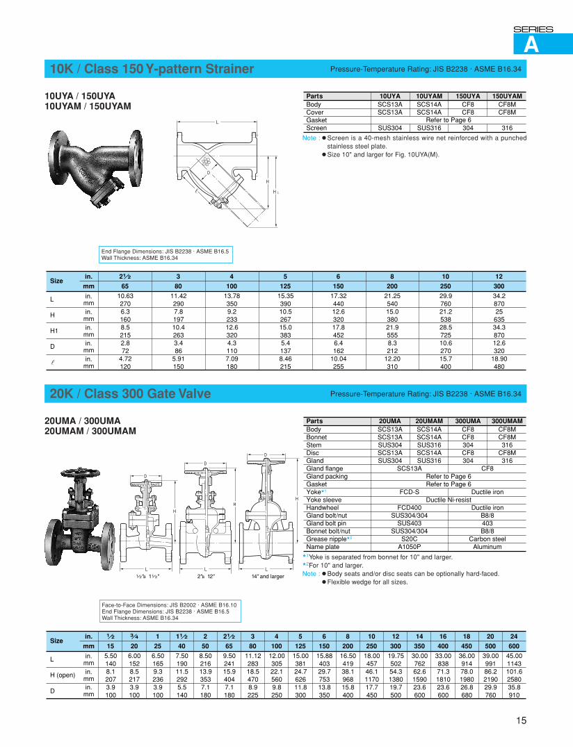
10K / Class 150 Y-pattern Strainer Pressure-Temperature Rating: JIS B2238 · ASME B16.34
10UYA / 150UYA10UYAM / 150UYAM
Note : � Screen is a 40-mesh stainless wire net reinforced with a punchedstainless steel plate.
� Size 10" and larger for Fig. 10UYA(M).
Face-to-Face Dimensions: JIS B2002 · ASME B16.10End Flange Dimensions: JIS B2238 · ASME B16.5Wall Thickness: ASME B16.34
20K / Class 300 Gate Valve Pressure-Temperature Rating: JIS B2238 · ASME B16.34
20UMA / 300UMA20UMAM / 300UMAM
�1Yoke is separated from bonnet for 10" and larger.�2For 10" and larger.Note : � Body seats and/or disc seats can be optionally hard-faced.
� Flexible wedge for all sizes.
PartsBodyCoverGasketScreen
10UYASCS13ASCS13A
SUS304
10UYAMSCS14ASCS14A
SUS316
150UYACF8CF8
304
150UYAMCF8MCF8M
316Refer to Page 6
in.
mm
in.mmin.
mm
Size
L
H
21 2
65
10.632706.31608.52152.872
4.72120
3
80
11.422907.819710.42633.486
5.91150
4
100
13.783509.223312.63204.31107.09180
5
125
15.3539010.526715.03835.41378.46215
6
150
17.3244012.632017.84526.4162
10.04255
8
200
21.2554015.038021.95558.3212
12.20310
10
250
29.976021.253828.572510.627015.7400
12
300
34.287025
63534.387012.6320
18.90480
in.mmin.
mm
H1
D
in.mm
PartsBodyBonnetStemDiscGlandGland flangeGland packingGasketYoke�1
Yoke sleeveHandwheelGland bolt/nutGland bolt pinBonnet bolt/nutGrease nipple�2
Name plate
20UMASCS13ASCS13ASUS304SCS13ASUS304
20UMAMSCS14ASCS14ASUS316SCS14ASUS316
SCS13A
FCD-S
FCD400SUS304/304
SUS403SUS304/304
S20CA1050P
300UMACF8CF8304CF8304
300UMAMCF8MCF8M316
CF8M316
CF8
Ductile iron
Ductile ironB8/8403B8/8
Carbon steelAluminum
Refer to Page 6Refer to Page 6
Ductile Ni-resist
1 2
15
in.
mm
in.mm
5.501408.12073.9100
in.mmin.
mm
Size
L
H (open)
D
3 4
20
11 2
40
21 2
65
6.001528.52173.9100
7.5019011.52925.5140
9.5024115.94047.1180
1
25
6.501659.32363.9100
2
50
8.5021613.93537.1180
3
80
11.1228318.54708.9225
4
100
12.0030522.15609.8250
5
125
15.0038124.762611.8300
6
150
15.8840329.775313.8350
8
200
16.5041938.196815.8400
10
250
18.0045746.1117017.7450
12
300
19.7550254.3138019.7500
14
350
30.0076262.6159023.6600
16
400
33.0083871.3181023.6600
18
450
36.0091478.0198026.8680
20
500
39.0099186.2219029.9760
24
600
45.001143101.6258035.8910
L
H
H1
D
D
L
H
D
L
H
D
L
H
1 2"~11 2" 2"~12" 14" and larger
A
16
Face-to-Face Dimensions: JIS B2002 · ASME B16.10End Flange Dimensions: JIS B2238 · ASME B16.5Wall Thickness: ASME B16.34
20K / Class 300 Globe Valve Pressure-Temperature Rating: JIS B2238 · ASME B16.34
20UPA / 300UPA20UPAM / 300UPAM
Note : Body seats and/or disc seats can be optionally hard-faced.Hammer-blow type handwheelfor 5" and 6"
�Hammer-blow type handwheel.
Face-to-Face Dimensions: JIS B2002 · ASME B16.10End Flange Dimensions: JIS B2238 · ASME B16.5Wall Thickness: ASME B16.34
20K / Class 300 Swing Check Valve Pressure-Temperature Rating: JIS B2238 · ASME B16.34
20UOA / 300UOA20UOAM / 300UOAM
�Size 3" and larger.Note : Body seats and/or disc seats can be optionally hard-faced.
PartsBodyBonnetStem
Disc
Lock nut
GlandGland flangeGland packingGasketYoke bushHandwheelGland bolt/nutGland bolt pinBonnet bolt/nutName plate
1 2"~11 2"2"~10"1 2"~11 2"2"~10"
20UPASCS13ASCS13ASUS304SUS304SCS13ASUS304SCS13ASUS304
20UPAMSCS14ASCS14ASUS316SUS316SCS14ASUS316SCS14ASUS316
SCS13A
FCD400SUS304/304
SUS403SUS304/304
A1050P
300UPACF8CF8304304CF8304CF8304
300UPAMCF8MCF8M316316
CF8M316
CF8M316
CF8
Ductile ironB8/8403B8/8
Aluminum
Refer to Page 6Refer to Page 6Ductile Ni-resist
1 2
15
in.
mm
in.mm
6.001527.31863.9100
in.mmin.
mm
Size
L
H (open)
D
3 4
20
11 2
40
21 2
65
7.001787.31863.9100
9.002299.32366.3160
11.5029211.72977.9200
1
25
8.002037.41873.9100
2
50
10.5026711.42897.1180
3
80
12.5031813.53439.8250
4
100
14.0035615.739811.8300
5
125
15.7540019.449313.8350
6
150
17.5044422.256415.8400
8
200
22.0055933.785719.7500
10
250
24.5062241.4105223.6600
PartsBodyCoverDiscGasketDisc nut�
Hinge pinPlugArm�
Washer�
Cover bolt/nutSplit pin
20UOASCS13ASCS13ASCS13A
SUS304SUS304SUS304SCS13A
20UOAMSCS14ASCS14ASCS14A
SUS316SUS316SUS316SCS14A
SUS316, SUS316L (3"~6")SUS304/304
SUS316L
300UOACF8CF8CF8
304304304CF8
300UOAMCF8MCF8MCF8M
316316316
CF8M316, 316L (3"~6")
B8/8316L
Refer to Page 6
in.
mm
in.mmin.
mm
Size
L
H
11 2
40
21 2
65
9.502414.6117
11.502926.3160
2
50
10.502675.3135
3
80
12.503187.1180
4
100
14.003567.9200
5
125
15.754009.1230
6
150
17.5044410.0255
8
200
21.0053311.6295
10
250
24.5062213.2335
12
300
28.0071114.8375
14
350
33.0083817.2437
16
400
34.0086418.9480
18
450
38.5097823.0585
20
500
40.00101623.8605
24
600
53.00134624.8630
D
L
H
D
L
H
2" and larger1 2"~11 2"
L
H
Disc type 21 2" and smaller
2" and smaller
6" and larger
3" and larger
A
17
Face-to-Face Dimensions: JIS B2002 · ASME B16.10End Flange Dimensions: JIS B2238 · ASME B16.5Wall Thickness: ASME B16.34
20K / Class 300 Lift Check Valve Pressure-Temperature Rating: JIS B2238 · ASME B16.34
20UNA / 300UNA20UNAM / 300UNAM
Note : Body seats and/or disc seats can be optionally hard-faced.
Face-to-Face Dimensions: ASME B16.10End Flange Dimensions: ASME B16.5Wall Thickness: ASME B16.34
Class 600 Gate Valve Pressure-Temperature Rating: ASME B16.34
600UMA600UMAM
�1Body seats and/or disc seats can be optionally hard-faced.�2Yoke is separated from bonnet for 8" and larger.�3For 2" and larger.�4For 6" and larger.Note : Flexible wedge for all sizes.
PartsBodyCoverDiscGasketCover bolt/nut
20UNASCS13ASCS13ASUS304
20UNAMSCS14ASCS14ASUS316
SUS304/304
300UNACF8CF8304
300UNAMCF8MCF8M316
B8/8Refer to Page 6
in.
mm
in.mmin.
mm
Size
L
H
11 2
40
9.002293.590
3 4
20
7.001782.973
1 2
15
6.001522.973
1
25
8.002032.973
PartsBodyBonnetStemDisc�1
GlandGland flangeGland packingGasketYoke�2
Yoke sleeveHandwheelGland bolt/nutGland bolt pinBonnet bolt/nutGrease nipple�3
Thrust bearing�4
Collar�3
Name plate
CF8CF8304CF8304
304
600UMA 600UMAMCF8MCF8M316
CF8M316
316
CF8Refer to Page 6Refer to Page 6
CF8Ductile Ni-resist
Ductile ironB8/8403B8/8
Carbon steelSteel
Aluminum
1 2
15
in.
mm
in.mm
6.501658.12073.9100
in.mmin.
mm
Size
L
H (open)
D
3 4
20
11 2
40
21 2
65
7.501908.72223.9100
9.5024113.23357.1180
13.0033018.94808.9225
1
25
8.502169.82505.5140
2
50
11.5029217.74507.9200
3
80
14.0035621.45449.8250
4
100
17.0043226.667613.8350
6
150
22.0055935.690517.7450
8
200
26.0066044.5113019.7500
10
250
31.0078752.3132823.6600
12
300
33.0083860.0152426.8680
L
H
D
L
H2" and smaller
21 2" and larger
A
18
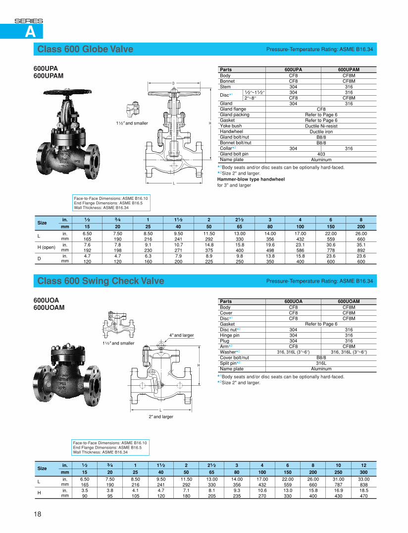
Class 600 Globe Valve Pressure-Temperature Rating: ASME B16.34
600UPA600UPAM
�1Body seats and/or disc seats can be optionally hard-faced.�2Size 2" and larger.Hammer-blow type handwheelfor 3" and larger
Face-to-Face Dimensions: ASME B16.10End Flange Dimensions: ASME B16.5Wall Thickness: ASME B16.34
Class 600 Swing Check Valve Pressure-Temperature Rating: ASME B16.34
600UOA600UOAM
�1Body seats and/or disc seats can be optionally hard-faced.�2Size 2" and larger.
Face-to-Face Dimensions: ASME B16.10End Flange Dimensions: ASME B16.5Wall Thickness: ASME B16.34
PartsBodyBonnetStem
Disc�1
GlandGland flangeGland packingGasketYoke bushHandwheelGland bolt/nutBonnet bolt/nutCollar�2
Gland bolt pinName plate
CF8CF8304304CF8304
304
600UPA 600UPAMCF8MCF8M316316
CF8M316
316
CF8Refer to Page 6Refer to Page 6Ductile Ni-resist
Ductile ironB8/8B8/8
403Aluminum
1 2"~11 2"2"~8"
1 2
15
in.
mm
in.mm
6.501657.61924.7120
in.mmin.
mm
Size
L
H (open)
D
3 4
20
11 2
40
21 2
65
7.501907.81984.7120
9.5024110.72717.9200
13.0033015.84009.8250
1
25
8.502169.12306.3160
2
50
11.5029214.83758.9225
3
80
14.0035619.649813.8350
4
100
17.0043223.158615.8400
6
150
22.0055930.677823.6600
8
200
26.0066035.189223.6600
PartsBodyCoverDisc�1
GasketDisc nut�2
Hinge pinPlugArm�2
Washer�2
Cover bolt/nutSplit pin�2
Name plate
600UOACF8CF8CF8
304304304CF8
316, 316L (3"~6")
600UOAMCF8MCF8MCF8M
316316316
CF8M316, 316L (3"~6")
Refer to Page 6
B8/8316L
Aluminum
1 2
15
in.
mm
in.mm
6.501653.590
in.mm
Size
L
H
3 4
20
11 2
40
21 2
65
7.501903.895
9.502414.7120
13.003308.1205
1
25
8.502164.1105
2
50
11.502927.1180
3
80
14.003569.3235
4
100
17.0043210.6270
6
150
22.0055913.0330
8
200
26.0066015.8400
10
250
31.0078716.9430
12
300
33.0083818.5470
D
L
H11 2" and smaller
L
H
11 2" and smaller
4" and larger
2" and larger
C
19
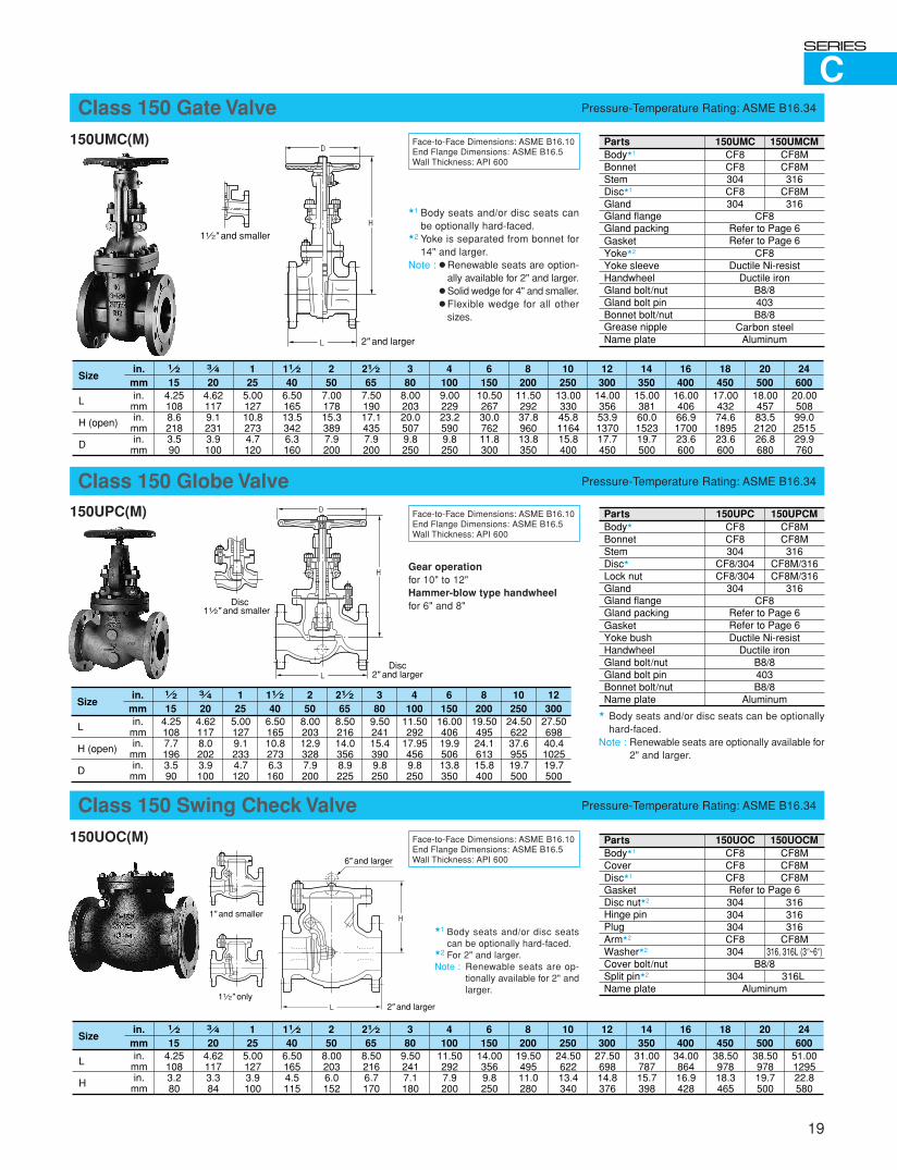
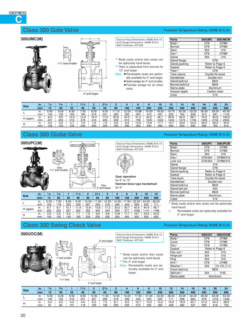
Class 150 Gate Valve Pressure-Temperature Rating: ASME B16.34
150UMC(M)
�1 Body seats and/or disc seats canbe optionally hard-faced.
�2 Yoke is separated from bonnet for14" and larger.
Note : � Renewable seats are option-ally available for 2" and larger.
� Solid wedge for 4" and smaller.� Flexible wedge for all other
sizes.
Face-to-Face Dimensions: ASME B16.10End Flange Dimensions: ASME B16.5Wall Thickness: API 600
PartsBody�1
BonnetStemDisc�1
GlandGland flangeGland packingGasketYoke�2
Yoke sleeveHandwheelGland bolt/nutGland bolt pinBonnet bolt/nutGrease nippleName plate
CF8CF8304CF8304
150UMC 150UMCMCF8MCF8M316
CF8M316
CF8Refer to Page 6Refer to Page 6
CF8Ductile Ni-resist
Ductile ironB8/8403B8/8
Carbon steelAluminum
1 2
15in.
mm4.251088.62183.590
in.mmin.
mmin.
mm
Size
L
H (open)
D
3 4
2011 2
4021 2
654.621179.12313.9100
6.5016513.53426.3160
7.5019017.14357.9200
125
5.0012710.82734.7120
250
7.0017815.33897.9200
380
8.0020320.05079.8250
41009.0022923.25909.8250
6150
10.5026730.076211.8300
8200
11.5029237.896013.8350
10250
13.0033045.8116415.8400
12300
14.0035653.9137017.7450
14350
15.0038160.0152319.7500
16400
16.0040666.9170023.6600
18450
17.0043274.6189523.6600
20500
18.0045783.5212026.8680
24600
20.0050899.0251529.9760
Class 150 Globe Valve Pressure-Temperature Rating: ASME B16.34
150UPC(M)
� Body seats and/or disc seats can be optionallyhard-faced.
Note : Renewable seats are optionally available for2" and larger.
Face-to-Face Dimensions: ASME B16.10End Flange Dimensions: ASME B16.5Wall Thickness: API 600
Gear operationfor 10" to 12"Hammer-blow type handwheelfor 6" and 8"
PartsBody�
BonnetStemDisc�
Lock nutGlandGland flangeGland packingGasketYoke bushHandwheelGland bolt/nutGland bolt pinBonnet bolt/nutName plate
CF8CF8304
CF8/304CF8/304
304
150UPC 150UPCMCF8MCF8M316
CF8M/316CF8M/316
316CF8
Refer to Page 6Refer to Page 6Ductile Ni-resist
Ductile ironB8/8403B8/8
Aluminum1 2
15in.
mm4.251087.71963.590
Size3 4
2011 2
4021 2
654.621178.02023.9100
6.5016510.82736.3160
8.5021614.03568.9225
125
5.001279.12334.7120
250
8.0020312.93287.9200
380
9.5024115.43909.8250
4100
11.50292
17.954569.8250
6150
16.0040619.950613.8350
8200
19.5049524.161315.8400
10250
24.5062237.695519.7500
12300
27.5069840.4102519.7500
in.mmin.
mmin.
mm
L
H (open)
D
Class 150 Swing Check Valve Pressure-Temperature Rating: ASME B16.34
150UOC(M)
�1 Body seats and/or disc seatscan be optionally hard-faced.
�2 For 2" and larger.Note : Renewable seats are op-
tionally available for 2" andlarger.
Face-to-Face Dimensions: ASME B16.10End Flange Dimensions: ASME B16.5Wall Thickness: API 600
PartsBody�1
CoverDisc�1
GasketDisc nut�2
Hinge pinPlugArm�2
Washer�2
Cover bolt/nutSplit pin�2
Name plate
CF8CF8CF8
304304304CF8304
304
150UOC 150UOCMCF8MCF8MCF8M
316316316
CF8M316, 316L (3"~6")
316L
Refer to Page 6
B8/8
Aluminum
1 2
15in.
mm4.251083.280
Size3 4
2011 2
4021 2
654.621173.384
6.501654.5115
8.502166.7170
125
5.001273.9100
250
8.002036.0152
380
9.502417.1180
4100
11.502927.9200
6150
14.003569.8250
8200
19.5049511.0280
10250
24.5062213.4340
12300
27.5069814.8376
14350
31.0078715.7398
16400
34.0086416.9428
18450
38.5097818.3465
20500
38.5097819.7500
24600
51.00129522.8580
in.mmin.
mm
L
H
D
L
H11 2" and smaller
2" and larger
L
H
11 2" only
6" and larger
2" and larger
1" and smaller
D
L
H
11 2" and smallerDisc
Disc2" and larger
CClass 300 Gate Valve Pressure-Temperature Rating: ASME B16.34
300UMC(M)
�1 Body seats and/or disc seats canbe optionally hard-faced.
�2 Yoke is separated from bonnet for12" and larger.
Note : � Renewable seats are option-ally available for 2" and larger.
� Solid wedge for 4" and smaller.� Flexible wedge for all other
sizes.
Face-to-Face Dimensions: ASME B16.10End Flange Dimensions: ASME B16.5Wall Thickness: API 600
Class 300 Globe Valve Pressure-Temperature Rating: ASME B16.34
300UPC(M)
� Body seats and/or disc seats can be optionallyhard-faced.
e : Renewable seats are optionally available for2" and larger.
Face-to-Face Dimensions: ASME B16.10End Flange Dimensions: ASME B16.5Wall Thickness: API 600
Gear operationfor 8" to 12"Hammer-blow type handwheelfor 6"
Class 300 Swing Check Valve Pressure-Temperature Rating: ASME B16.34
300UOC(M)
�1 Body seats and/or disc seatscan be optionally hard-faced.
�2 For 2" and larger.Note : Renewable seats are op-
tionally available for 2" andlarger.
Face-to-Face Dimensions: ASME B16.10End Flange Dimensions: ASME B16.5Wall Thickness: API 600
20
D
L
H11 2" and smaller
2" and larger
L
H
11 2" only
4" and larger
2" and larger
1" and smaller
PartsBody�1
BonnetStemDisc�1
GlandGland flangeGland packingGasketYoke�2
Yoke sleeveHandwheelGland bolt/nutBonnet bolt/nutName plateGrease nippleCollar
CF8CF8304CF8304
300UMC 300UMCMCF8MCF8M316
CF8M316
CF8Refer to Page 6Refer to Page 6
CF8Ductile Ni-resist
Ductile ironB8/8B8/8
AluminumCarbon steel
316
�1 2
15in.
mm5.501408.92273.9100
Size3 4
2011 2
4021 2
656.001529.82503.9100
7.5019014.93787.9200
9.5024117.94557.9200
125
6.5016512.23104.7120
250
8.5021616.44167.9200
380
11.1228320.85289.8250
4100
12.0030524.26159.8250
6150
15.8840331.479813.8350
8200
16.5041940.2102015.8400
10250
18.0045748.1122217.7450
12300
19.7550256.8144219.7500
14350
30.0076262.0157523.6600
16400
33.0083868.7174523.6600
18450
36.0091476.6194526.8680
20500
39.0099184.8215529.9760
24600
45.001143100.6255535.8910
in.mmin.
mmin.
mm
L
H (open)
D
PartsBody�
BonnetStemDisc�
Lock nutGlandGland flangeGland packingGasketYoke bushHandwheelGland bolt/nutGland bolt pinBonnet bolt/nutName plateCollar
CF8CF8304
CF8/304CF8/304
300UPC 300UPCMCF8MCF8M316
CF8M/316CF8M/316
316CF8
Refer to Page 6Refer to Page 6Ductile Ni-resist
Ductile ironB8/8403B8/8
Aluminum316
1 2
15in.
mm6.001528.72203.9100
Size3 4
2011 2
4021 2
657.001788.72223.9100
9.0022911.93027.1180
11.5029215.84009.8250
125
8.0020310.12575.5140
250
10.5026713.93527.9200
380
12.5031817.34409.8250
4100
14.0035620.050913.8350
6150
17.5044426.767717.7450
8200
22.0055940.9103819.7500
10250
24.5062244.9114123.6600
12300
28.0071146.7118623.6600
in.mmin.
mmin.
mm
L
H (open)
D
PartsBody�1
CoverDisc�1
GasketDisc nut�2
Hinge pinPlugArm�2
Washer�2
Cover bolt/nutSplit pin�2
Name plate
CF8CF8CF8
304304304CF8304
304
300UOC 300UOCMCF8MCF8MCF8M
316316316
CF8M316, 316L (3"~6")
316L
Refer to Page 6
B8/8
Aluminum
1 2
15in.
mm5.501403.281
Size3 4
2011 2
4021 2
656.001523.384
9.502414.6118
11.502927.5190
125
8.502164.0101
250
10.502676.5165
380
12.503188.1205
4100
14.003568.9225
6150
17.5044410.7272
8200
21.0053313.0330
10250
24.5062214.2360
12300
28.0071116.0406
14350
33.0083818.9480
16400
34.0086420.7527
18450
38.5097821.9555
20500
40.00101624.3618
24600
53.00134628.8732
in.mmin.
mm
L
H
D
L
H
11 2" and smallerDisc
Disc2" and larger
C
21
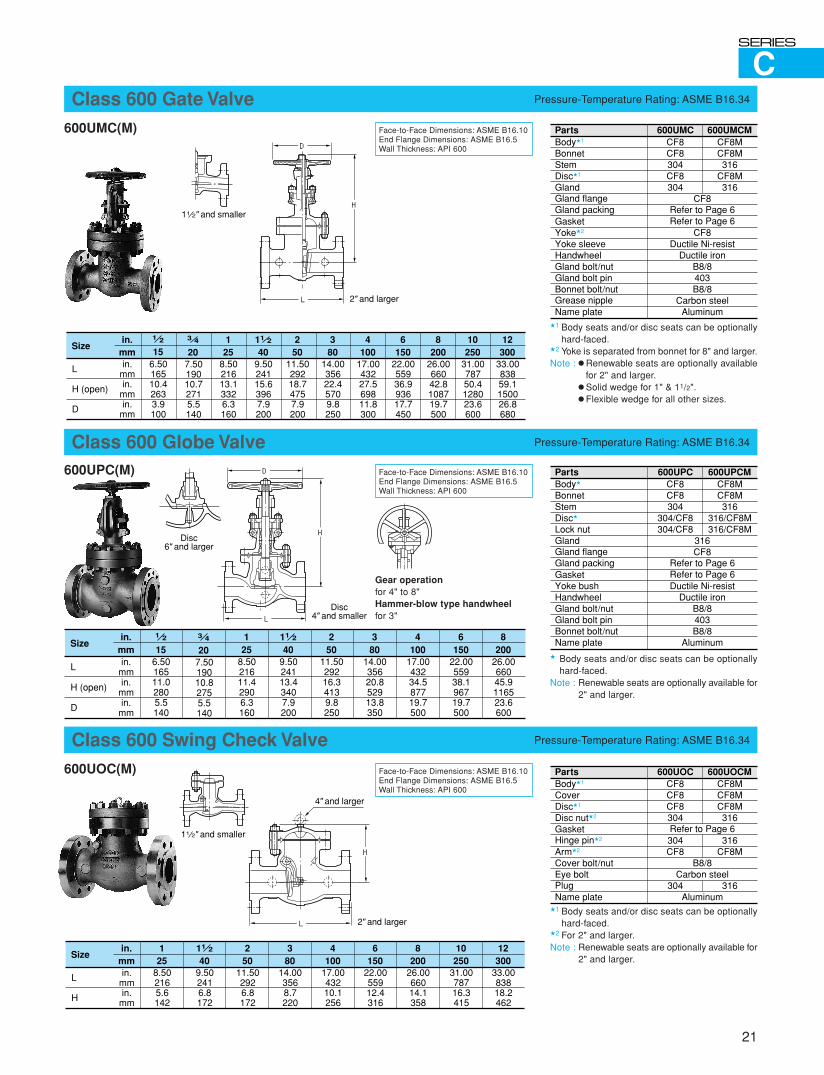
Class 600 Gate Valve Pressure-Temperature Rating: ASME B16.34
600UMC(M)
�1 Body seats and/or disc seats can be optionallyhard-faced.
�2 Yoke is separated from bonnet for 8" and larger.Note : � Renewable seats are optionally available
for 2" and larger.� Solid wedge for 1" & 11/2".� Flexible wedge for all other sizes.
Face-to-Face Dimensions: ASME B16.10End Flange Dimensions: ASME B16.5Wall Thickness: API 600
Class 600 Globe Valve Pressure-Temperature Rating: ASME B16.34
600UPC(M)
� Body seats and/or disc seats can be optionallyhard-faced.
Note : Renewable seats are optionally available for2" and larger.
Face-to-Face Dimensions: ASME B16.10End Flange Dimensions: ASME B16.5Wall Thickness: API 600
Gear operationfor 4" to 8"Hammer-blow type handwheelfor 3"
Class 600 Swing Check Valve Pressure-Temperature Rating: ASME B16.34
600UOC(M)
�1 Body seats and/or disc seats can be optionallyhard-faced.
�2 For 2" and larger.Note : Renewable seats are optionally available for
2" and larger.
Face-to-Face Dimensions: ASME B16.10End Flange Dimensions: ASME B16.5Wall Thickness: API 600
PartsBody�1
BonnetStemDisc�1
GlandGland flangeGland packingGasketYoke�2
Yoke sleeveHandwheelGland bolt/nutGland bolt pinBonnet bolt/nutGrease nippleName plate
CF8CF8304CF8304
600UMC 600UMCMCF8MCF8M316
CF8M316
CF8Refer to Page 6Refer to Page 6
CF8Ductile Ni-resist
Ductile ironB8/8403B8/8
Carbon steelAluminum
in.mm
Size11 2
409.5024115.63967.9200
125
8.5021613.13326.3160
250
11.5029218.74757.9200
380
14.0035622.45709.8250
4100
17.0043227.569811.8300
6150
22.0055936.993617.7450
8200
26.0066042.8108719.7500
10250
31.0078750.4128023.6600
12300
33.0083859.1150026.8680
in.mmin.
mmin.
mm
L
H (open)
D
3 4
207.5019010.72715.5140
1 2
156.5016510.42633.9100
PartsBody�
BonnetStemDisc�
Lock nutGlandGland flangeGland packingGasketYoke bushHandwheelGland bolt/nutGland bolt pinBonnet bolt/nutName plate
CF8CF8304
304/CF8304/CF8
600UPC 600UPCMCF8MCF8M316
316/CF8M316/CF8M
316CF8
Refer to Page 6Refer to Page 6Ductile Ni-resist
Ductile ironB8/8403B8/8
Aluminumin.
mmSize
11 2
409.5024113.43407.9200
125
8.5021611.42906.3160
250
11.5029216.34139.8250
380
14.0035620.852913.8350
4100
17.0043234.587719.7500
6150
22.0055938.196719.7500
8200
26.0066045.9116523.6600
in.mmin.
mmin.
mm
L
H (open)
D
3 4
207.5019010.82755.5140
1 2
156.5016511.02805.5140
PartsBody�1
CoverDisc�1
Disc nut�2
GasketHinge pin�2
Arm�2
Cover bolt/nutEye boltPlugName plate
CF8CF8CF8304
304CF8
304
600UOC 600UOCMCF8MCF8MCF8M316
316CF8M
316
Refer to Page 6
B8/8Carbon steel
Aluminum
in.mm
Size11 2
409.502416.8172
125
8.502165.6142
250
11.502926.8172
380
14.003568.7220
4100
17.0043210.1256
6150
22.0055912.4316
8200
26.0066014.1358
10250
31.0078716.3415
12300
33.0083818.2462
in.mmin.
mm
L
H
D
L
H11 2" and smaller
2" and larger
D
L
HDisc
6" and larger
Disc4" and smaller
L
H
11 2" and smaller
4" and larger
2" and larger
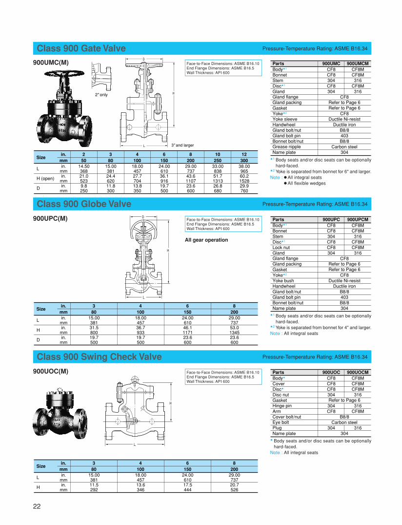
Class 900 Gate Valve Pressure-Temperature Rating: ASME B16.34
900UMC(M)
�1 Body seats and/or disc seats can be optionallyhard-faced.
�2 Yoke is separated from bonnet for 6" and larger.Note : � All integral seats
� All flexible wedges
Face-to-Face Dimensions: ASME B16.10End Flange Dimensions: ASME B16.5Wall Thickness: API 600
Class 900 Globe Valve Pressure-Temperature Rating: ASME B16.34
900UPC(M) Face-to-Face Dimensions: ASME B16.10End Flange Dimensions: ASME B16.5Wall Thickness: API 600
All gear operation
Class 900 Swing Check Valve Pressure-Temperature Rating: ASME B16.34
900UOC(M) Face-to-Face Dimensions: ASME B16.10End Flange Dimensions: ASME B16.5Wall Thickness: API 600
22
�1 Body seats and/or disc seats can be optionallyhard-faced.
�2 Yoke is separated from bonnet for 4" and larger.Note : All integral seats
� Body seats and/or disc seats can be optionallyhard-faced.
Note : All integral seats
PartsBody�1
BonnetStemDisc�1
GlandGland flangeGland packingGasketYoke�2
Yoke sleeveHandwheelGland bolt/nutGland bolt pinBonnet bolt/nutGrease nippleName plate
CF8CF8304CF8304
900UMC 900UMCMCF8MCF8M316
CF8M316
CF8Refer to Page 6Refer to Page 6
CF8Ductile Ni-resist
Ductile ironB8/8403B8/8
Carbon steel304in.
mmSize
250
14.5036821.05239.8250
380
15.0038124.462011.8300
4100
18.0045727.770413.8350
6150
24.0061036.191619.7500
8200
29.0073743.6110723.6600
10250
33.0083851.7131326.8680
12300
38.0096560.2152829.9760
in.mmin.
mmin.
mm
L
H (open)
D
PartsBody�1
BonnetStemDisc�1
Lock nutGlandGland flangeGland packingGasketYoke�2
Yoke bushHandwheelGland bolt/nutGland bolt pinBonnet bolt/nutName plate
CF8CF8304CF8CF8304
900UPC 900UPCMCF8MCF8M316
CF8MCF8M316
CF8Refer to Page 6Refer to Page 6
CF8Ductile Ni-resist
Ductile ironB8/8403B8/8304in.
mmSize
380
15.0038131.580019.7500
4100
18.0045736.793319.7500
6150
24.0061046.1117123.6600
8200
29.0073753.0134523.6600
in.mmin.
mmin.
mm
L
H
D
PartsBody�
CoverDisc�
Disc nutGasketHinge pinArmCover bolt/nutEye boltPlugName plate
CF8CF8CF8304
304CF8
304
900UOC 900UOCMCF8MCF8MCF8M316
316CF8M
316
Refer to Page 6
B8/8Carbon steel
304
in.mm
Size3
8015.0038111.5292
4100
18.0045713.6346
6150
24.0061017.5444
8200
29.0073720.7526
in.mmin.
mm
L
H
D
L
H
3" and larger
L
H
2" only
D
L
H
23
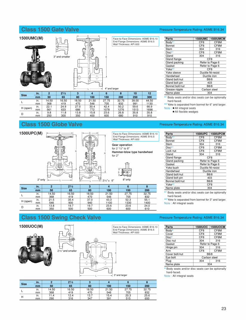
Class 1500 Gate Valve Pressure-Temperature Rating: ASME B16.34
1500UMC(M)
�1 Body seats and/or disc seats can be optionallyhard-faced.
�2 Yoke is separated from bonnet for 6" and larger.Note : � All integral seats
� All flexible wedges
Face-to-Face Dimensions: ASME B16.10End Flange Dimensions: ASME B16.5Wall Thickness: API 600
Class 1500 Globe Valve Pressure-Temperature Rating: ASME B16.34
1500UPC(M) Face-to-Face Dimensions: ASME B16.10End Flange Dimensions: ASME B16.5Wall Thickness: API 600
Gear operationfor 2 1/2" to 8"Hammer-blow type handwheelfor 2"
Class 1500 Swing Check Valve Pressure-Temperature Rating: ASME B16.34
1500UOC(M) Face-to-Face Dimensions: ASME B16.10End Flange Dimensions: ASME B16.5Wall Thickness: API 600
�1 Body seats and/or disc seats can be optionallyhard-faced.
�2 Yoke is separated from bonnet for 3" and larger.Note : All integral seats
� Body seats and/or disc seats can be optionallyhard-faced.
Note : All integral seats
PartsBody�1
BonnetStemDisc�1
GlandGland flangeGland packingGasketYoke�2
Yoke sleeveHandwheelGland bolt/nutGland bolt pinBonnet bolt/nutGrease nippleName plate
CF8CF8304CF8304
1500UMC 1500UMCMCF8MCF8M316
CF8M316
CF8Refer to Page 6Refer to Page 6
CF8Ductile Ni-resist
Ductile ironB8/8403B8/8
Carbon steel304in.
mmSize
21 2
6516.5041924.963311.8300
250
14.5036822.15619.8250
380
18.5047027.068613.8350
4100
21.5054630.477215.8400
6150
27.7570542.4107823.6600
8200
32.7583250.2127626.8680
10250
39.0099159.6151335.8910
12300
44.50113066.9169835.8910
in.mmin.
mmin.
mm
L
H (open)
D
PartsBody�1
BonnetStemDisc�1
Lock nutGlandGland flangeGland packingGasketYoke bushHandwheelGland bolt/nutGland bolt pinBonnet bolt/nutYoke�2
Name plate
CF8CF8304CF8CF8304
1500UPC 1500UPCMCF8MCF8M316
CF8MCF8M316
CF8Refer to Page 6Refer to Page 6Ductile Ni-resist
Ductile ironB8/8403B8/8CF8304in.
mmSize
21 2
6516.5041935.490019.7500
250
14.5036821.554613.8350
380
18.5047037.094019.7500
4100
21.5054643.3110023.6600
6150
27.7570552.3133023.6600
8200
32.7583255.1140024.0610
in.mmin.
mmin.
mm
L
H (open)
D
PartsBody�
CoverDisc�
Disc nutGasketHinge pinArmCover bolt/nutEye boltPlugName plate
CF8CF8CF8304
304CF8
304
1500UOC 1500UOCMCF8MCF8MCF8M316
316CF8M
316
Refer to Page 6
B8/8Carbon steel
304
in.mm
Size21 2
6516.5041912.4316
250
14.5036811.4290
380
18.5047013.7347
4100
21.5054615.4391
6150
27.7570520.3515
8200
32.7583225.6650
in.mmin.
mm
L
H
D
L
H
4" and larger
L
H
3" and larger
3" and smaller
D D
L L
HH
D
21 2" ~ 6" 8" only2" only
21 2" and smaller
B
24
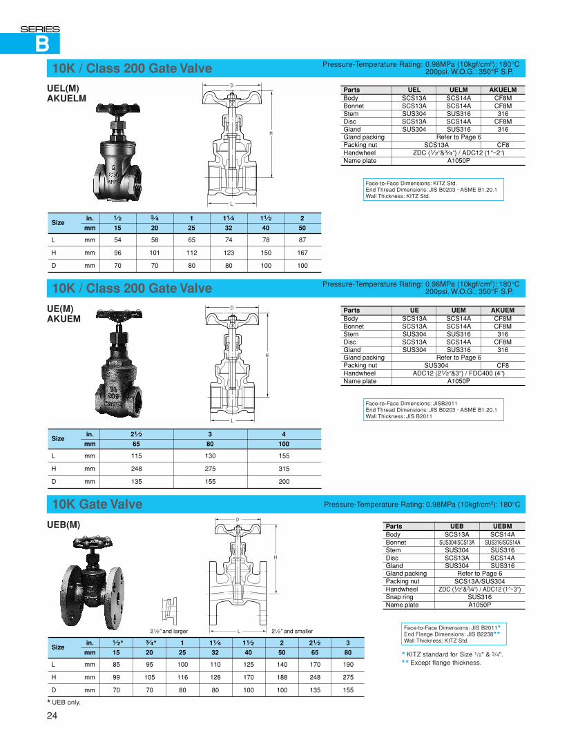
Face-to-Face Dimensions: KITZ Std.End Thread Dimensions: JIS B0203 · ASME B1.20.1Wall Thickness: KITZ Std.
10K / Class 200 Gate Valve Pressure-Temperature Rating: 0.98MPa (10kgf/cm2): 180°C200psi. W.O.G.: 350°F S.P.
UEL(M)AKUELM
PartsBodyBonnetStemDiscGlandGland packingPacking nutHandwheelName plate
SCS13ASCS13ASUS304SCS13ASUS304
UEL UELMSCS14ASCS14ASUS316SCS14ASUS316
Refer to Page 6
ZDC (1 2"&3 4") / ADC12 (1"~2")A1050P
SCS13A
AKUELMCF8MCF8M316
CF8M316
CF8
Face-to-Face Dimensions: JISB2011End Thread Dimensions: JIS B0203 · ASME B1.20.1Wall Thickness: JIS B2011
10K / Class 200 Gate Valve Pressure-Temperature Rating: 0.98MPa (10kgf/cm2): 180°C200psi. W.O.G.: 350°F S.P.
UE(M)AKUEM
Face-to-Face Dimensions: JIS B2011�
End Flange Dimensions: JIS B2238��
Wall Thickness: KITZ Std.
UEB(M)
10K Gate Valve Pressure-Temperature Rating: 0.98MPa (10kgf/cm2): 180°C
� KITZ standard for Size 1/2" & 3/4".�� Except flange thickness.
1 2
15
in.
mm
54
96
70
mm
mm
mm
L
H
D
Size3 4
20
11 2
40
58
101
70
78
150
100
11 4
32
74
123
80
1
25
65
112
80
2
50
87
167
100
PartsBodyBonnetStemDiscGlandGland packingPacking nutHandwheelName plate
SCS13ASCS13ASUS304SCS13ASUS304
UE UEMSCS14ASCS14ASUS316SCS14ASUS316
Refer to Page 6
ADC12 (21 2"&3") / FDC400 (4")A1050P
SUS304
AKUEMCF8MCF8M316
CF8M316
CF8
PartsBodyBonnetStemDiscGlandGland packingPacking nutHandwheelSnap ringName plate
SCS13ASUS304/SCS13A
SUS304SCS13ASUS304
UEB UEBMSCS14A
SUS316/SCS14ASUS316SCS14ASUS316
Refer to Page 6SCS13A/SUS304
ZDC (1 2"&3 4") / ADC12 (1"~3")SUS316A1050P
1 2�
15
in.
mm
85
99
70
mm
mm
mm
L
H
D
Size 3 4�
20
95
105
70
11 2
40
125
170
100
21 2
65
170
248
135
11 4
32
110
128
80
1
25
100
116
80
2
50
140
188
100
3
80
190
275
155
� UEB only.
D
L
H
D
L
H
D
L
H
21 2" and larger 21 2" and smaller
in.
mm
mm
mm
mm
L
H
D
Size21 2
65
115
248
135
3
80
130
275
155
4
100
155
315
200
B
25
Face-to-Face Dimensions: KITZ Std.End Flange Dimensions: JIS B2238�
Wall Thickness: JIS B2011
UAB
5K Globe Valve Pressure-Temperature Rating: 0.49MPa (5kgf/cm2): 150°C
� Except flange thickness.
End-to-End Dimensions: KITZ Std.End Thread Dimensions: JIS B0203 · ASME B1.20.1Wall Thickness: JIS B2011
10K / Class 200 Globe Valve Pressure-Temperature Rating: 0.98MPa (10kgf/cm2): 180°C200psi. W.O.G.: 350°F S.P.
End-to-End Dimensions: JIS B2011 · KITZ Std.End Thread Dimensions: JIS B0203 · ASME B1.20.1Wall Thickness: JIS B2011
10K / Class 200 Globe Valve Pressure-Temperature Rating: 0.98MPa (10kgf/cm2): 180°C200psi. W.O.G.: 350°F S.P.
UJ(M)AKUJM
� For 21/2" and larger.Note : Size 21/2" and larger for Fig. UJ / UJM.
PartsBodyBonnetStemDiscGlandGland packingPacking nutHandwheelName plate
UABSCS13ASCS13ASUS304SUS304SUS304
Refer to Page 6SCS13A/SUS304
ZDC (3 8"~3 4") / ADC12 (1"~2")A1050P
in.
mm
mm
mm
mm
L
H (open)
D
Size11 2
40
135
155
90
11 4
32
120
142
90
3 8
10
73
106
70
1 2
15
85
106
70
3 4
20
95
108
70
1
25
108
119
80
2
50
155
186
115
PartsBodyBonnetStemDiscGlandGland packingPacking nutHandwheelName plate
SCS13ASCS13ASUS304SUS304SUS304
SCS13A
UCL AKUCLMCF8MCF8M316316316
CF8Refer to Page 6
ZDC (1 4"~ 1") / ADC (11 4"~2")A1050P
in.
mm
mm
mm
mm
L
H (open)
D
Size11 2
40
90
138
90
11 4
32
80
122
80
3 8
10
48
68
55
1 2
15
52
68
55
3 4
20
60
93
60
1 4
8
44
68
55
1
25
72
100
70
2
50
100
153
100
PartsBodyBonnetStemDiscGlandLock nutGland packingPacking nut
Handwheel
Bonnet ring�
Gasket�
Packing washerStem washerName plate
SCS13ASCS13ASUS304
SUS304/SCS13ASUS304SUS304
ZDC (3 8"~3 4")
SCS13A
UJ UJMSCS14ASCS14ASUS316
SUS316/SCS14ASUS316SUS316
Refer to Page 6
ADC12 (1"~2")
SCS14AAsbestos sheet
A1050P
SCS13A/SUS304
FCD400 (21 2" & 3")
SUS316SUS316
AKUJMCF8MCF8M316316316316
304/CF8ZDC (3 8"~3 4")
ADC12 (1"~2")—
316316
in.
mm
mm
mm
mm
L
H (open)
D
Size11 2
40
120
171
100
21 2
65
180
253
180
11 4
32
105
150
90
3 8
10
55
109
60
1 2
15
65
111
60
3 4
20
80
112
70
1
25
90
142
90
2
50
140
189
115
3
80
200
280
225
D
L
H
D
L
H
D
L
H
21 2" and larger
2" and smaller
UCLAKUCLM
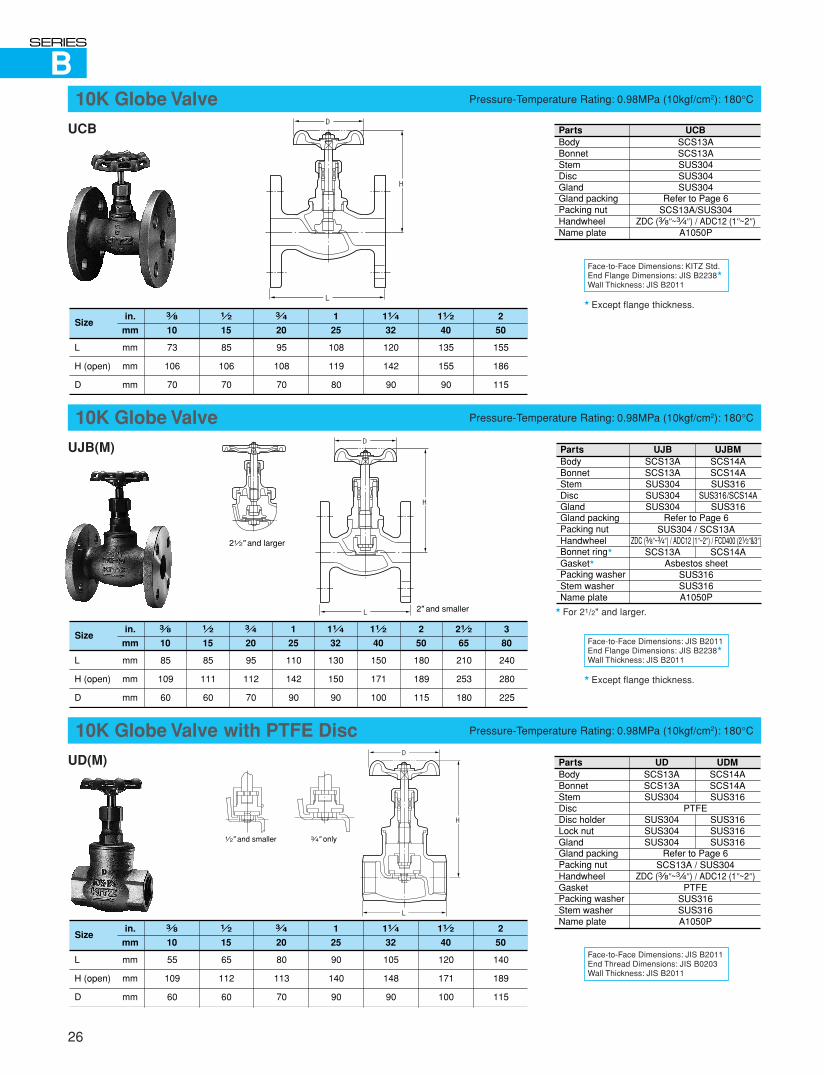
B
Face-to-Face Dimensions: KITZ Std.End Flange Dimensions: JIS B2238�
Wall Thickness: JIS B2011
UCB
10K Globe Valve Pressure-Temperature Rating: 0.98MPa (10kgf/cm2): 180°C
� Except flange thickness.
Face-to-Face Dimensions: JIS B2011End Flange Dimensions: JIS B2238�
Wall Thickness: JIS B2011
UJB(M)
10K Globe Valve Pressure-Temperature Rating: 0.98MPa (10kgf/cm2): 180°C
� Except flange thickness.
Face-to-Face Dimensions: JIS B2011End Thread Dimensions: JIS B0203Wall Thickness: JIS B2011
UD(M)
10K Globe Valve with PTFE Disc Pressure-Temperature Rating: 0.98MPa (10kgf/cm2): 180°C
26
PartsBodyBonnetStemDiscGlandGland packingPacking nutHandwheelName plate
UCBSCS13ASCS13ASUS304SUS304SUS304
Refer to Page 6SCS13A/SUS304
ZDC (3 8"~3 4") / ADC12 (1"~2")A1050P
in.
mm
mm
mm
mm
L
H (open)
D
Size11 2
40
135
155
90
11 4
32
120
142
90
3 8
10
73
106
70
1 2
15
85
106
70
3 4
20
95
108
70
1
25
108
119
80
2
50
155
186
115
PartsBodyBonnetStemDiscGlandGland packingPacking nutHandwheelBonnet ring�
Gasket�
Packing washerStem washerName plate
SCS13ASCS13ASUS304SUS304SUS304
SCS13A
UJB UJBMSCS14ASCS14ASUS316
SUS316/SCS14ASUS316
SCS14A
Refer to Page 6SUS304 / SCS13A
ZDC (3 8"~3 4") / ADC12 (1"~2") / FCD400 (21 2"&3")
Asbestos sheetSUS316SUS316A1050P
� For 21/2" and larger.
in.
mm
mm
mm
mm
L
H (open)
D
Size11 2
40
150
171
100
21 2
65
210
253
180
11 4
32
130
150
90
3 8
10
85
109
60
1 2
15
85
111
60
3 4
20
95
112
70
1
25
110
142
90
2
50
180
189
115
3
80
240
280
225
PartsBodyBonnetStemDiscDisc holderLock nutGlandGland packingPacking nutHandwheelGasketPacking washerStem washerName plate
SCS13ASCS13ASUS304
SUS304SUS304SUS304
UD UDMSCS14ASCS14ASUS316
SUS316SUS316SUS316
PTFE
Refer to Page 6SCS13A / SUS304
ZDC (3 8"~3 4") / ADC12 (1"~2")PTFE
SUS316SUS316A1050P
in.
mm
mm
mm
mm
L
H (open)
D
Size11 2
40
120
171
100
11 4
32
105
148
90
3 8
10
55
109
60
1 2
15
65
112
60
3 4
20
80
113
70
1
25
90
140
90
2
50
140
189
115
D
L
H
D
L
H
2" and smaller
21 2" and larger
D
L
H
3 4" only1 2" and smaller
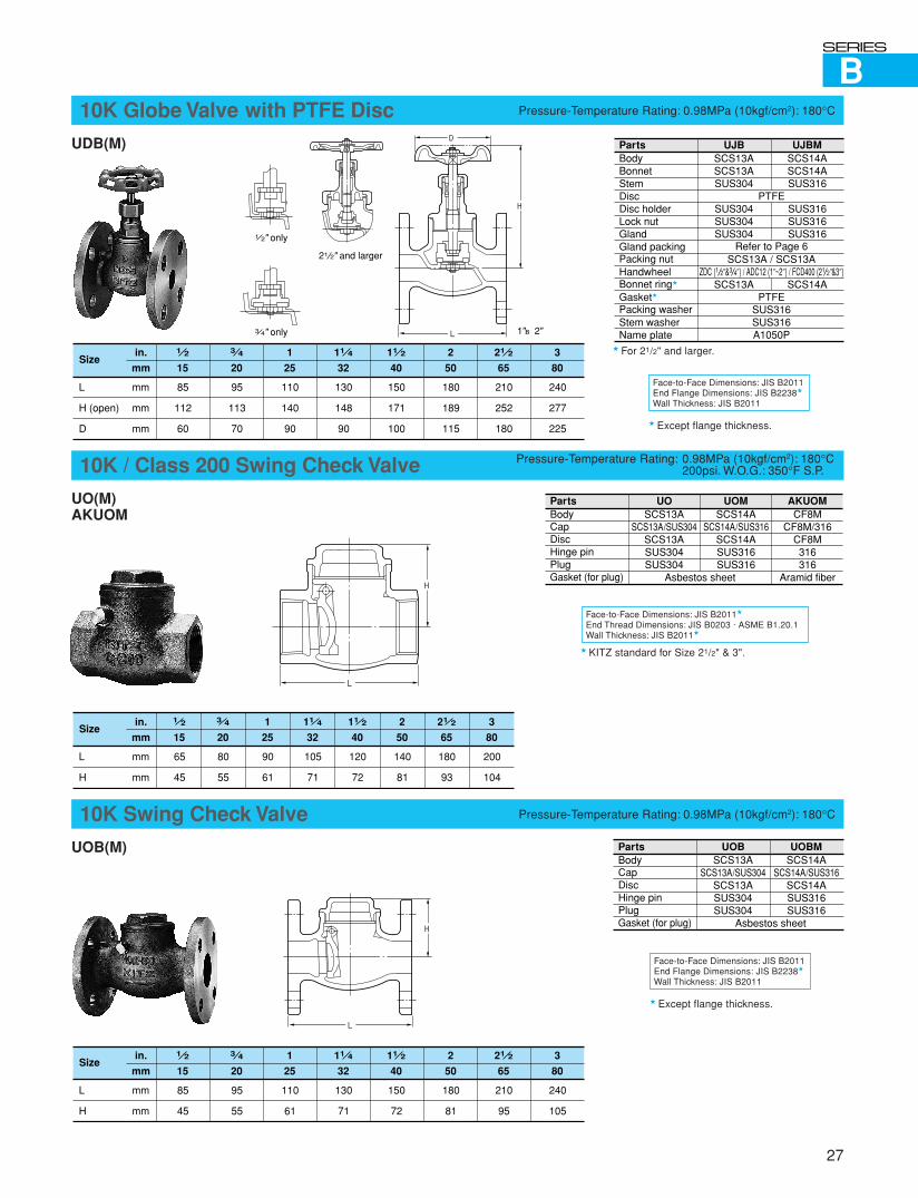
B
27
Face-to-Face Dimensions: JIS B2011End Flange Dimensions: JIS B2238�
Wall Thickness: JIS B2011
UDB(M)
10K Globe Valve with PTFE Disc Pressure-Temperature Rating: 0.98MPa (10kgf/cm2): 180°C
� Except flange thickness.
UO(M)AKUOM
� KITZ standard for Size 21/2" & 3".
UOB(M)
10K Swing Check Valve Pressure-Temperature Rating: 0.98MPa (10kgf/cm2): 180°C
Face-to-Face Dimensions: JIS B2011�
End Thread Dimensions: JIS B0203 · ASME B1.20.1Wall Thickness: JIS B2011�
10K / Class 200 Swing Check Valve Pressure-Temperature Rating: 0.98MPa (10kgf/cm2): 180°C200psi. W.O.G.: 350°F S.P.
Face-to-Face Dimensions: JIS B2011End Flange Dimensions: JIS B2238�
Wall Thickness: JIS B2011
� Except flange thickness.
PartsBodyBonnetStemDiscDisc holderLock nutGlandGland packingPacking nutHandwheelBonnet ring�
Gasket�
Packing washerStem washerName plate
SCS13ASCS13ASUS304
SUS304SUS304SUS304
SCS13A
UJB UJBMSCS14ASCS14ASUS316
SUS316SUS316SUS316
SCS14A
PTFE
Refer to Page 6SCS13A / SCS13A
ZDC (1 2"&3 4") / ADC12 (1"~2") / FCD400 (21 2"&3")
PTFESUS316SUS316A1050P
in.
mm
mm
mm
mm
L
H (open)
D
Size11 2
40
150
171
100
21 2
65
210
252
180
11 4
32
130
148
90
1 2
15
85
112
60
3 4
20
95
113
70
1
25
110
140
90
2
50
180
189
115
3
80
240
277
225
PartsBodyCapDiscHinge pinPlugGasket (for plug)
SCS13ASCS13A/SUS304
SCS13ASUS304SUS304
UO UOMSCS14A
SCS14A/SUS316SCS14ASUS316SUS316
Asbestos sheet
AKUOMCF8M
CF8M/316CF8M316316
Aramid fiber
in.
mm
mm
mm
L
H
Size11 2
40
120
72
21 2
65
180
93
11 4
32
105
71
1 2
15
65
45
3 4
20
80
55
1
25
90
61
2
50
140
81
3
80
200
104
PartsBodyCapDiscHinge pinPlugGasket (for plug)
SCS13ASCS13A/SUS304
SCS13ASUS304SUS304
UOB UOBMSCS14A
SCS14A/SUS316SCS14ASUS316SUS316
Asbestos sheet
in.
mm
mm
mm
L
H
Size11 2
40
150
72
21 2
65
210
95
11 4
32
130
71
1 2
15
85
45
3 4
20
95
55
1
25
110
61
2
50
180
81
3
80
240
105
D
L
H
21 2" and larger
1 2" only
3 4" only 1"~2"
� For 21/2" and larger.
L
H
L
H
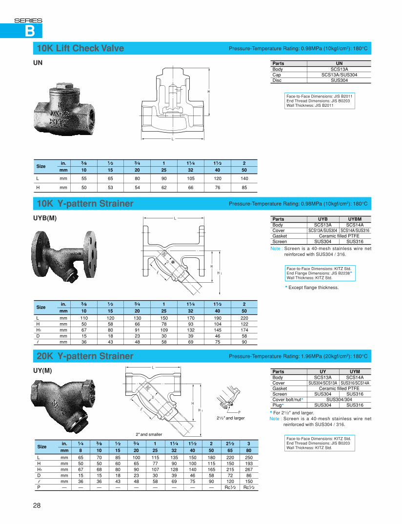
B
Face-to-Face Dimensions: JIS B2011End Thread Dimensions: JIS B0203Wall Thickness: JIS B2011
UN
10K Lift Check Valve Pressure-Temperature Rating: 0.98MPa (10kgf/cm2): 180°C
UYB(M)
10K Y-pattern Strainer Pressure-Temperature Rating: 0.98MPa (10kgf/cm2): 180°C
UY(M)
20K Y-pattern Strainer Pressure-Temperature Rating: 1.96MPa (20kgf/cm2): 180°C
Face-to-Face Dimensions: KITZ Std.End Flange Dimensions: JIS B2238�
Wall Thickness: KITZ Std.
� Except flange thickness.
Note : Screen is a 40-mesh stainless wire netreinforced with SUS304 / 316.
Face-to-Face Dimensions: KITZ Std.End Thread Dimensions: JIS B0203Wall Thickness: KITZ Std.
� For 21/2" and larger.Note : Screen is a 40-mesh stainless wire net
reinforced with SUS304 / 316.
PartsBodyCapDisc
UNSCS13A
SCS13A/SUS304SUS304
in.
mm
mm
mm
L
H
Size11 2
40
120
76
11 4
32
105
66
3 8
10
55
50
1 2
15
65
53
3 4
20
80
54
1
25
90
62
2
50
140
85
PartsBodyCoverGasketScreen
SCS13ASCS13A/SUS304
SUS304
UYB UYBMSCS14A
SCS14A/SUS316
SUS316Ceramic filled PTFE
in.
mm
mmmmmmmmmm
LHH1
D
Size11 2
40
1901041454675
11 4
32
170931323969
3 8
10
11050671536
1 2
15
12058801843
3 4
20
13066912348
1
25
15078
1093058
2
50
2201221745890
PartsBodyCoverGasketScreenCover bolt/nut�
Plug�
SCS13ASUS304/SCS13A
SUS304
SUS304
UY UYMSCS14A
SUS316/SCS14A
SUS316
SUS316
Ceramic filled PTFE
SUS304/304
in.
mm
mmmmmmmmmm—
LHH1
D
P
Size11 2
40
1501001404675—
21 2
65
22015021572120
Rc1 2
11 4
32
135901283969—
3 8
10
7050681536—
1 2
15
8560801843—
3 4
20
10065902348—
1 4
8
6550671536—
1
25
11577
1073058—
2
50
1801151655890—
3
80
25019326786150
Rc1 2
28
L
H
L
H1
HD
L
H1
H
P
D
21 2" and larger
2" and smaller

D
29
End-to-End Dimensions: KITZ Std.Connecting Threads: ASME B1.20.1Connecting Sockets: ASME B16.11Wall Thickness: ASME B16.34
AK 150UMM Threaded EndsAW150UMM Socket Welding Ends
Class 150 Gate Valve Pressure-Temperature Rating: ASME B16.34
Note : Flexible wedge for all sizes.
PartsBodyBonnetStemDiscGlandGland packingGland flangeHandwheelGasketBonnet bolt/nutGland bolt/nutYoke sleeveName plate
MaterialCF3MCF8M316
CF8M316
Refer to Page 6CF8
Ductile ironRefer to Page 6
B8/8B8/8
Ductile Ni-resistAluminum
1 2
15
in.
mmin.
mmin.
mmin.
mm
2.75707.71953.590
Size
L
H (open)
D
3 4
20
11 2
403.076
8.032043.590
4.5114
10.872765.5140
1
25
AK150UMM
3.5898.72203.9100
2
504.7512113.23366.3160
1 2
152.6677.71953.590
3 4
20
11 2
402.973
8.032043.590
4.4111
10.872765.5140
1
25
AW150UMM
3.4868.72203.9100
2
504.611813.23366.3160
End-to-End Dimensions: KITZ Std.Connecting Threads: ASME B1.20.1Connecting Sockets: ASME B16.11Wall Thickness: ASME B16.34
AK 150UPM Threaded EndsAW150UPM Socket Welding Ends
Class 150 Globe Valve Pressure-Temperature Rating: ASME B16.34
End-to-End Dimensions: KITZ Std.Connecting Threads: ASME B1.20.1Connecting Sockets: ASME B16.11Wall Thickness: ASME B16.34
AK 150UOM Threaded EndsAW150UOM Socket Welding Ends
Class 150 Swing Check Valve Pressure-Temperature Rating: ASME B16.34
PartsBodyBonnetStemDiscLock nutGlandGland packingHandwheelGasketGland flangeBonnet bolt/nutGland bolt/nutYoke bushName plate
MaterialCF3MCF8M316316316316
Refer to Page 6Ductile iron
Refer to Page 6CF8B8/8B8/8
Ductile Ni-resistAluminum
1 2
15
in.
mmin.
mmin.
mmin.
mm
3.4866.51643.590
Size
L
H (open)
D
3 4
20
11 2
403.75956.51663.590
5.51407.81985.5140
1
25
AK150UPM
4.251086.71693.9100
2
506.51659.12306.3160
1 2
153.3836.51643.590
3 4
20
11 2
403.6926.51663.590
5.41377.81985.5140
1
25
AW150UPM
4.11056.71693.9100
2
506.41629.12306.3160
PartsBodyCoverDiscHinge pinPlugGasketCover bolt/nutName plate
MaterialCF3MCF8MCF8M316316
Refer to Page 6B8/8
Aluminum
1 2
15
in.
mmin.
mmin.
mm
3.75952.870
Size
L
H
3 4
20
11 2
403.75953.075
6.01524.1104
1
25
AK150UOM
5.01273.281
2
506.51654.7120
1 2
153.6922.870
3 4
20
11 2
403.6923.075
5.91494.1104
1
25
AW150UOM
4.91243.281
2
506.41624.7120
D
L
H
D
L
H
D
L
H
D
L
H
L
H
L
H
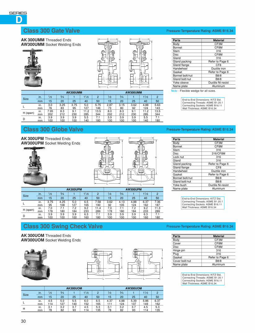
D
End-to-End Dimensions: KITZ Std.Connecting Threads: ASME B1.20.1Connecting Sockets: ASME B16.11Wall Thickness: ASME B16.34
AK 300UMM Threaded EndsAW300UMM Socket Welding Ends
Class 300 Gate Valve Pressure-Temperature Rating: ASME B16.34
Note : Flexible wedge for all sizes.
End-to-End Dimensions: KITZ Std.Connecting Threads: ASME B1.20.1Connecting Sockets: ASME B16.11Wall Thickness: ASME B16.34
AK 300UPM Threaded EndsAW300UPM Socket Welding Ends
Class 300 Globe Valve Pressure-Temperature Rating: ASME B16.34
End-to-End Dimensions: KITZ Std.Connecting Threads: ASME B1.20.1Connecting Sockets: ASME B16.11Wall Thickness: ASME B16.34
AK 300UOM Threaded EndsAW300UOM Socket Welding Ends
Class 300 Swing Check Valve Pressure-Temperature Rating: ASME B16.34
PartsBodyBonnetStemDiscGlandGland packingGland flangeHandwheelGasketBonnet bolt/nutGland bolt/nutYoke sleeveName plate
MaterialCF3MCF8M316
CF8M316
Refer to Page 6CF8
Ductile ironRefer to Page 6
B8/8B8/8
Ductile Ni-resistAluminum
1 2
15
in.
mmin.
mmin.
mmin.
mm
3.076
7.952023.9100
Size
L
H (open)
D
3 4
20
11 2
403.25838.32123.9100
5.012711.22855.5140
1
25
AK300UMM
3.75959.12303.9100
2
505.7514613.53447.1180
1 2
152.87738.02023.9100
3 4
20
11 2
403.15808.32123.9100
4.8812411.22855.5140
1
25
AW300UMM
3.62929.12303.9100
2
505.6314313.53447.1180
PartsBodyBonnetStemDiscLock nutGlandGland packingGland flangeHandwheelGasketBonnet bolt/nutGland bolt/nutYoke bushName plate
MaterialCF3MCF8M316
316/CF8M316316
Refer to Page 6CF8
Ductile ironRefer to Page 6
B8/8B8/8
Ductile Ni-resistAluminum
1 2
15
in.
mmin.
mmin.
mmin.
mm
3.75957.01783.9100
Size
L
H (open)
D
3 4
20
11 2
404.251087.11803.9100
6.51659.22336.3160
1
25
AK300UPM
5.01277.21843.9100
2
507.5819011.42897.1180
1 2
153.62927.01783.9100
3 4
20
11 2
404.131057.11803.9100
6.371629.22336.3160
1
25
AW300UPM
4.881247.21843.9100
2
507.3618711.32897.1180
PartsBodyCoverDiscHinge pinPlugGasketCover bolt/nutName plate
MaterialCF3MCF8MCF8M316316
Refer to Page 6B8/8
Aluminum
1 2
15
in.
mmin.
mmin.
mm
4.51143.178
Size
L
H
3 4
20
11 2
405.01273.282
6.01524.5114
1
25
AK300UOM
5.51403.793
2
506.51655.3135
1 2
154.371113.178
3 4
20
11 2
404.881243.282
5.861494.5114
1
25
AW300UOM
5.391373.793
2
506.371625.3135
30
D
L
H
D
L
H
D
L
H
D
L
H
L
H
L
H
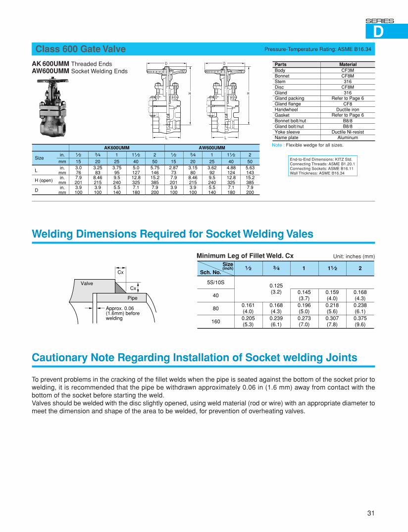
D
31
End-to-End Dimensions: KITZ Std.Connecting Threads: ASME B1.20.1Connecting Sockets: ASME B16.11Wall Thickness: ASME B16.34
AK 600UMM Threaded EndsAW600UMM Socket Welding Ends
Class 600 Gate Valve Pressure-Temperature Rating: ASME B16.34
Note : Flexible wedge for all sizes.
PartsBodyBonnetStemDiscGlandGland packingGland flangeHandwheelGasketBonnet bolt/nutGland bolt/nutYoke sleeveName plate
MaterialCF3MCF8M316
CF8M316
Refer to Page 6CF8
Ductile ironRefer to Page 6
B8/8B8/8
Ductile Ni-resistAluminum
1 2
15
in.
mmin.
mmin.
mmin.
mm
3.0767.92013.9100
Size
L
H (open)
D
3 4
20
11 2
403.2583
8.462153.9100
5.012712.83257.1180
1
25
AK600UMM
3.75959.52405.5140
2
505.7514615.23857.9200
1 2
152.87737.92013.9100
3 4
20
11 2
403.1580
8.462153.9100
4.8812412.83257.1180
1
25
AW600UMM
3.62929.52405.5140
2
505.6314315.23857.9200
Welding Dimensions Required for Socket Welding Vales
Cautionary Note Regarding Installation of Socket welding Joints
To prevent problems in the cracking of the fillet welds when the pipe is seated against the bottom of the socket prior towelding, it is recommended that the pipe be withdrawn approximately 0.06 in (1.6 mm) away from contact with thebottom of the socket before starting the weld.Valves should be welded with the disc slightly opened, using weld material (rod or wire) with an appropriate diameter tomeet the dimension and shape of the area to be welded, for prevention of overheating valves.
Minimum Leg of Fillet Weld. Cx
1 2Size(inch)
5S/10S
40
80
160
0.161(4.0)0.205(5.3)
0.125(3.2)
0.168(4.3)0.239(6.1)
0.145(3.7)0.196(5.0)0.273(7.0)
0.159(4.0)0.218(5.6)0.307(7.8)
0.168(4.3)0.238(6.1)0.375(9.6)
Sch. No.3 4 11 21 2
Cx
Cx
Pipe
Valve
Approx. 0.06(1.6mm) beforewelding
Unit: inches (mm)
D
L
H
D
L
H
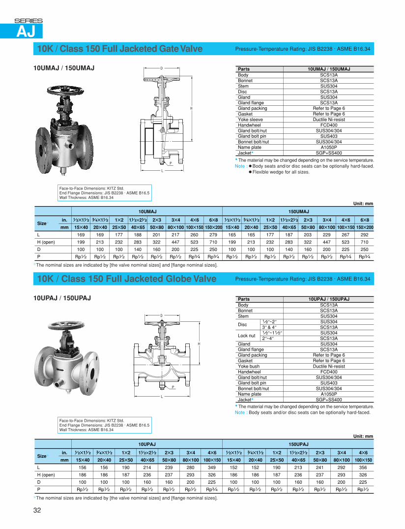
AJ
32
Face-to-Face Dimensions: KITZ Std.End Flange Dimensions: JIS B2238 · ASME B16.5Wall Thickness: ASME B16.34
10K / Class 150 Full Jacketed Gate Valve Pressure-Temperature Rating: JIS B2238 · ASME B16.34
10UMAJ / 150UMAJ
� The material may be changed depending on the service temperature.Note : � Body seats and/or disc seats can be optionally hard-faced.
� Flexible wedge for all sizes.
✩The nominal sizes are indicated by [the valve nominal sizes] and [flange nominal sizes].
PartsBodyBonnetStemDiscGlandGland flangeGland packingGasketYoke sleeveHandwheelGland bolt/nutGland bolt pinBonnet bolt/nutName plateJacket�
SCS13ASCS13ASUS304SCS13ASUS304SCS13A
Refer to Page 6Refer to Page 6Ductile Ni-resist
FCD400SUS304/304
SUS403SUS304/304
A1050PSGP+SS400
10UMAJ / 150UMAJ
1 2✕11 2
15✕40
in.
mm
10UMAJ
169
199
100
Rp1 2
L
H (open)
D
P
Size✩
3 4✕11 2
20✕40
169
213
100
Rp1 2
1✕2
25✕50
177
232
100
Rp1 2
2✕3
50✕80
201
322
160
Rp1 2
3✕4
80✕100
217
447
200
Rp1 2
4✕6
100✕150
260
523
225
Rp3 4
6✕8
150✕200
279
710
250
Rp3 4
11 2✕21 2
40✕65
188
283
140
Rp1 2
1 2✕11 2
15✕40
150UMAJ
Unit: mm
165
199
100
Rp1 2
3 4✕11 2
20✕40
165
213
100
Rp1 2
1✕2
25✕50
177
232
100
Rp1 2
2✕3
50✕80
203
322
160
Rp1 2
3✕4
80✕100
229
447
200
Rp1 2
4✕6
100✕150
267
523
225
Rp3 4
6✕8
150✕200
292
710
250
Rp3 4
11 2✕21 2
40✕65
187
283
140
Rp1 2
Face-to-Face Dimensions: KITZ Std.End Flange Dimensions: JIS B2238 · ASME B16.5Wall Thickness: ASME B16.34
10K / Class 150 Full Jacketed Globe Valve Pressure-Temperature Rating: JIS B2238 · ASME B16.34
10UPAJ / 150UPAJ
� The material may be changed depending on the service temperature.Note : Body seats and/or disc seats can be optionally hard-faced.
✩The nominal sizes are indicated by [the valve nominal sizes] and [flange nominal sizes].
PartsBodyBonnetStem
Disc
Lock nut
GlandGland flangeGland packingGasketYoke bushHandwheelGland bolt/nutGland bolt pinBonnet bolt/nutName plateJacket�
SCS13ASCS13ASUS304SUS304SCS13ASUS304SCS13ASUS304SCS13A
Refer to Page 6Refer to Page 6Ductile Ni-resist
FCD400SUS304/304
SUS403SUS304/304
A1050PSGP+SS400
10UPAJ / 150UPAJ
1 2"~2"3" & 4"1 2"~11 2"2"~4"
1 2✕11 2
15✕40
in.
mm
10UPAJ
156
186
100
Rp1 2
L
H (open)
D
P
Size✩
3 4✕11 2
20✕40
156
186
100
Rp1 2
1✕2
25✕50
190
187
100
Rp1 2
2✕3
50✕80
239
237
160
Rp1 2
3✕4
80✕100
280
293
200
Rp1 2
4✕6
100✕150
349
326
225
Rp3 4
11 2✕21 2
40✕65
214
236
160
Rp1 2
1 2✕11 2
15✕40
150UPAJ
Unit: mm
152
186
100
Rp1 2
3 4✕11 2
20✕40
152
186
100
Rp1 2
1✕2
25✕50
190
187
100
Rp1 2
2✕3
50✕80
241
237
160
Rp1 2
3✕4
80✕100
292
293
200
Rp1 2
4✕6
100✕150
356
326
225
Rp1 2
11 2✕21 2
40✕65
213
236
160
Rp1 2
D
L
H
P
D
L
H
P

AJ
33
Face-to-Face Dimensions: KITZ Std.End Flange Dimensions: JIS B2238 · ASME B16.5Wall Thickness: ASME B16.34
10K / Class 150 Full Jacketed Lift Check Valve Pressure-Temperature Rating: JIS B2238 · ASME B16.34
10UNAJ / 150UNAJ
� The material may be changed depending on the service temperature.Note : Body seats and/or disc seats can be optionally hard-faced.
✩The nominal sizes are indicated by [the valve nominal sizes] and [flange nominal sizes].
Face-to-Face Dimensions: KITZ Std.End Flange Dimensions: JIS B2238 · ASME B16.5Wall Thickness: ASME B16.34
10K / Class 150 Full Jacketed Swing Check Valve Pressure-Temperature Rating: JIS B2238 · ASME B16.34
10UOAJ / 150UOAJ
� The material may be changed depending on the service temperature.Note : Body seats and/or disc seats can be optionally hard-faced.
✩The nominal sizes are indicated by [the valve nominal sizes] and [flange nominal sizes].
PartsBodyCoverDiscGasketHinge pinPlugCover bolt/nutSplit pinJacket�
SCS13ASCS13ASCS13A
Refer to Page 6SUS304SUS304
SUS304/304SUS316L
SGP+SS400
10UOAJ / 150UOAJ
in.
mm
10UOAJ
L
H
P
Size✩2✕3
50✕80
239
122
Rp1 2
3✕4
80✕100
280
149
Rp1 2
4✕6
100✕150
349
171
Rp3 4
6✕8
150✕200
393
214
Rp3 4
2✕3
50✕80
241
122
Rp1 2
3✕4
80✕100
292
149
Rp1 2
4✕6
100✕150
356
171
Rp3 4
6✕8
150✕200
406
214
Rp3 4
150UOAJ
Unit: mm
PartsBodyCoverDiscGasketCover bolt/nutJacket�
SCS13ASCS13ASUS304
Refer to Page 6SUS304/304SGP+SS400
10UNAJ / 150UNAJ
1 2✕11 2
15✕40
in.
mm
10UNAJ
156
73
Rp1 2
L
H
P
Size✩
3 4✕11 2
20✕40
156
73
Rp1 2
1✕2
25✕50
190
73
Rp1 2
11 2✕21 2
40✕65
214
90
Rp1 2
1 2✕11 2
15✕40
152
73
Rp1 2
3 4✕11 2
20✕40
152
73
Rp1 2
1✕2
25✕50
190
73
Rp1 2
11 2✕21 2
40✕65
213
90
Rp1 2
150UNAJ
Unit: mm
L
H
P
A A
L
H
P
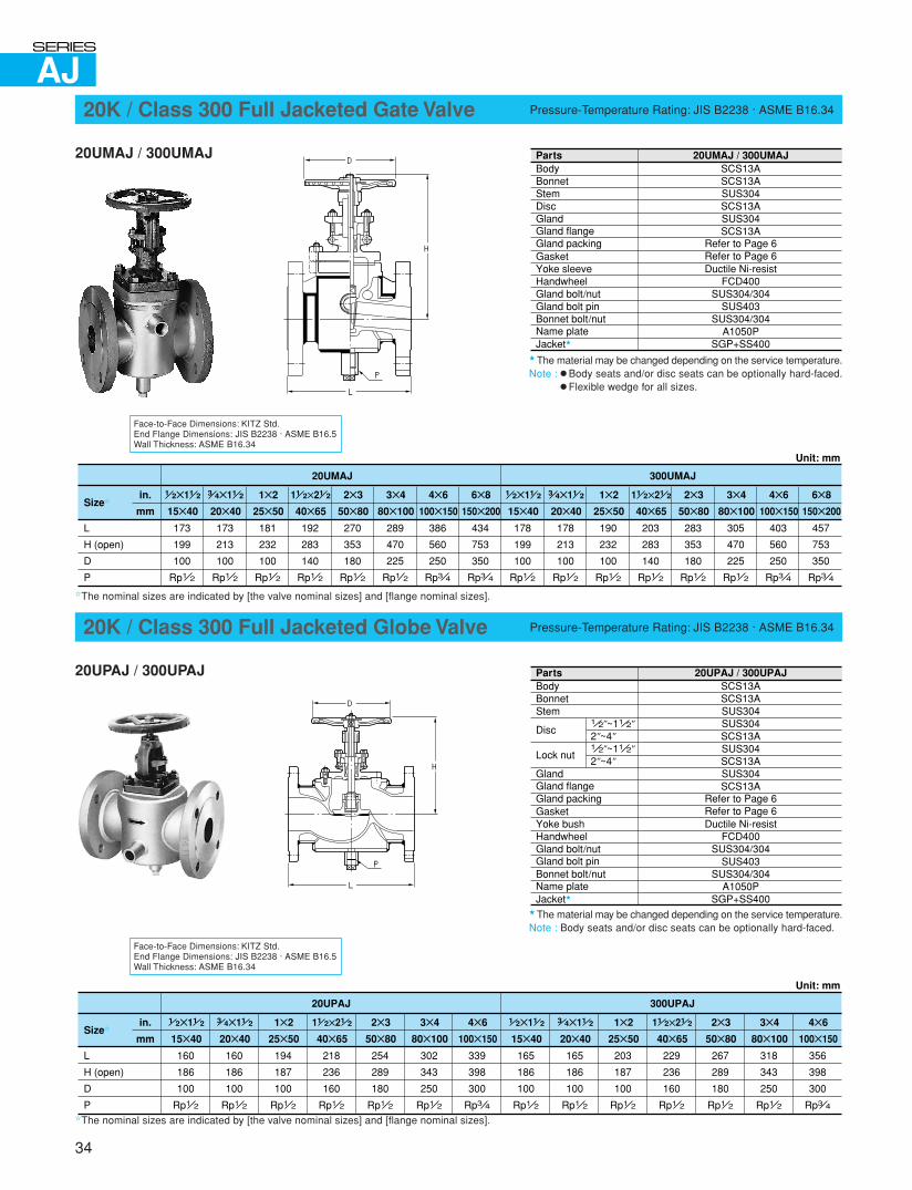
AJ
Face-to-Face Dimensions: KITZ Std.End Flange Dimensions: JIS B2238 · ASME B16.5Wall Thickness: ASME B16.34
20K / Class 300 Full Jacketed Gate Valve Pressure-Temperature Rating: JIS B2238 · ASME B16.34
20UMAJ / 300UMAJ
� The material may be changed depending on the service temperature.Note : � Body seats and/or disc seats can be optionally hard-faced.
� Flexible wedge for all sizes.
✩The nominal sizes are indicated by [the valve nominal sizes] and [flange nominal sizes].
Face-to-Face Dimensions: KITZ Std.End Flange Dimensions: JIS B2238 · ASME B16.5Wall Thickness: ASME B16.34
20K / Class 300 Full Jacketed Globe Valve Pressure-Temperature Rating: JIS B2238 · ASME B16.34
20UPAJ / 300UPAJ
� The material may be changed depending on the service temperature.Note : Body seats and/or disc seats can be optionally hard-faced.
✩The nominal sizes are indicated by [the valve nominal sizes] and [flange nominal sizes].
34
PartsBodyBonnetStemDiscGlandGland flangeGland packingGasketYoke sleeveHandwheelGland bolt/nutGland bolt pinBonnet bolt/nutName plateJacket�
SCS13ASCS13ASUS304SCS13ASUS304SCS13A
Refer to Page 6Refer to Page 6Ductile Ni-resist
FCD400SUS304/304
SUS403SUS304/304
A1050PSGP+SS400
20UMAJ / 300UMAJ
�1 2✕11 2
15✕40
in.
mm
20UMAJ
173
199
100
Rp1 2
L
H (open)
D
P
Size✩
3 4✕11 2
20✕40
173
213
100
Rp1 2
1✕2
25✕50
181
232
100
Rp1 2
2✕3
50✕80
270
353
180
Rp1 2
3✕4
80✕100
289
470
225
Rp1 2
4✕6
100✕150
386
560
250
Rp3 4
6✕8
150✕200
434
753
350
Rp3 4
11 2✕21 2
40✕65
192
283
140
Rp1 2
1 2✕11 2
15✕40
300UMAJ
Unit: mm
178
199
100
Rp1 2
3 4✕11 2
20✕40
178
213
100
Rp1 2
1✕2
25✕50
190
232
100
Rp1 2
2✕3
50✕80
283
353
180
Rp1 2
3✕4
80✕100
305
470
225
Rp1 2
4✕6
100✕150
403
560
250
Rp3 4
6✕8
150✕200
457
753
350
Rp3 4
11 2✕21 2
40✕65
203
283
140
Rp1 2
PartsBodyBonnetStem
Disc
Lock nut
GlandGland flangeGland packingGasketYoke bushHandwheelGland bolt/nutGland bolt pinBonnet bolt/nutName plateJacket�
SCS13ASCS13ASUS304SUS304SCS13ASUS304SCS13ASUS304SCS13A
Refer to Page 6Refer to Page 6Ductile Ni-resist
FCD400SUS304/304
SUS403SUS304/304
A1050PSGP+SS400
20UPAJ / 300UPAJ
1 2"~11 2"2"~4"
1 2"~11 2"2"~4"
1 2✕11 2
15✕40
in.
mm
20UPAJ
160
186
100
Rp1 2
L
H (open)
D
P
Size✩
3 4✕11 2
20✕40
160
186
100
Rp1 2
1✕2
25✕50
194
187
100
Rp1 2
2✕3
50✕80
254
289
180
Rp1 2
3✕4
80✕100
302
343
250
Rp1 2
4✕6
100✕150
339
398
300
Rp3 4
11 2✕21 2
40✕65
218
236
160
Rp1 2
1 2✕11 2
15✕40
300UPAJ
Unit: mm
165
186
100
Rp1 2
3 4✕11 2
20✕40
165
186
100
Rp1 2
1✕2
25✕50
203
187
100
Rp1 2
2✕3
50✕80
267
289
180
Rp1 2
3✕4
80✕100
318
343
250
Rp1 2
4✕6
100✕150
356
398
300
Rp3 4
11 2✕21 2
40✕65
229
236
160
Rp1 2
D
L
P
H
D
L
H
P
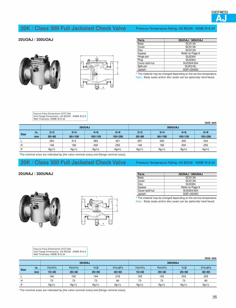
AJ
Face-to-Face Dimensions: KITZ Std.End Flange Dimensions: JIS B2238 · ASME B16.5Wall Thickness: ASME B16.34
20K / Class 300 Full Jacketed Check Valve Pressure-Temperature Rating: JIS B2238 · ASME B16.34
20UNAJ / 300UNAJ
� The material may be changed depending on the service temperature.Note : Body seats and/or disc seats can be optionally hard-faced.
✩The nominal sizes are indicated by [the valve nominal sizes] and [flange nominal sizes].
Face-to-Face Dimensions: KITZ Std.End Flange Dimensions: JIS B2238 · ASME B16.5Wall Thickness: ASME B16.34
20K / Class 300 Full Jacketed Check Valve Pressure-Temperature Rating: JIS B2238 · ASME B16.34
20UOAJ / 300UOAJ
� The material may be changed depending on the service temperature.Note : Body seats and/or disc seats can be optionally hard-faced.
✩The nominal sizes are indicated by [the valve nominal sizes] and [flange nominal sizes].
35
PartsBodyCoverDiscGasketHinge pinPlugCover bolt/nutSplit pinJacket�
SCS13ASCS13ASCS13A
Refer to Page 6SUS304SUS304
SUS304/304SUS316L
SGP+SS400
20UOAJ / 300UOAJ
in.
mm
20UOAJ
L
H
P
Size✩2✕3
50✕80
254
146
Rp1 2
3✕4
80✕100
314
180
Rp1 2
4✕6
100✕150
383
200
Rp3 4
6✕8
150✕200
421
255
Rp3 4
2✕3
50✕80
267
146
Rp1 2
3✕4
80✕100
330
180
Rp1 2
4✕6
100✕150
400
200
Rp3 4
6✕8
150✕200
444
255
Rp3 4
300UOAJ
Unit: mm
PartsBodyCoverDiscGasketCover bolt/nutJacket�
SCS13ASCS13ASUS304
Refer to Page 6SUS304/304SGP+SS400
20UNAJ / 300UNAJ
1 2✕11 2
15✕40
in.
mm
20UNAJ
160
73
Rp1 2
L
H
P
Size✩
3 4✕11 2
20✕40
160
73
Rp1 2
1✕2
25✕50
194
73
Rp1 2
11 2✕21 2
40✕65
218
90
Rp1 2
1 2✕11 2
15✕40
165
73
Rp1 2
3 4✕11 2
20✕40
165
73
Rp1 2
1✕2
25✕50
203
73
Rp1 2
11 2✕21 2
40✕65
229
90
Rp1 2
300UNAJ
Unit: mm
L
H
P
A A
L
H
P
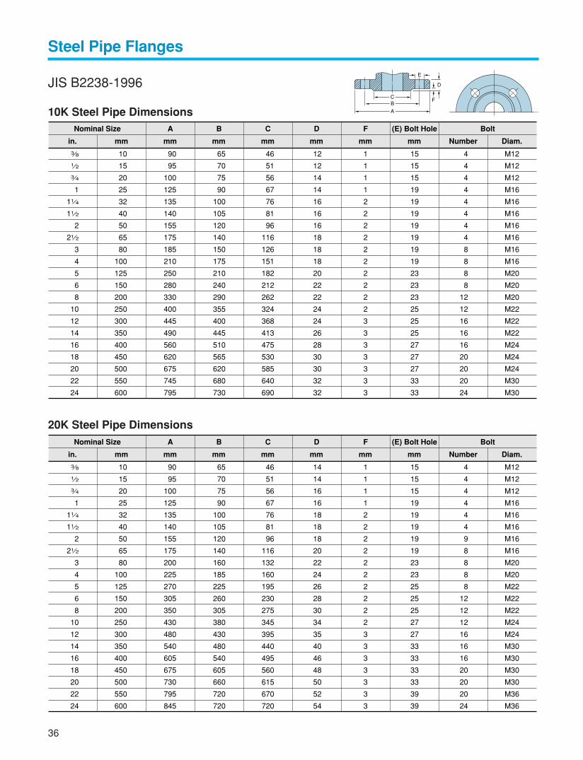
Steel Pipe Flanges
36
JIS B2238-1996
10K Steel Pipe Dimensions
20K Steel Pipe Dimensions
10
15
20
25
32
40
50
65
80
100
125
150
200
250
300
350
400
450
500
550
600
3 8
1 2
3 4
1
11 4
11 2
2
21 2
3
4
5
6
8
10
12
14
16
18
20
22
24
90
95
100
125
135
140
155
175
185
210
250
280
330
400
445
490
560
620
675
745
795
65
70
75
90
100
105
120
140
150
175
210
240
290
355
400
445
510
565
620
680
730
46
51
56
67
76
81
96
116
126
151
182
212
262
324
368
413
475
530
585
640
690
12
12
14
14
16
16
16
18
18
18
20
22
22
24
24
26
28
30
30
32
32
1
1
1
1
2
2
2
2
2
2
2
2
2
2
3
3
3
3
3
3
3
15
15
15
19
19
19
19
19
19
19
23
23
23
25
25
25
27
27
27
33
33
4
4
4
4
4
4
4
4
8
8
8
8
12
12
16
16
16
20
20
20
24
M12
M12
M12
M16
M16
M16
M16
M16
M16
M16
M20
M20
M20
M22
M22
M22
M24
M24
M24
M30
M30
Nominal Size
in. mm
A
mm
B
mm
C
mm
D
mm
F
mm
(E) Bolt Hole Bolt
mm Number Diam.
10
15
20
25
32
40
50
65
80
100
125
150
200
250
300
350
400
450
500
550
600
3 8
1 2
3 4
1
11 4
11 2
2
21 2
3
4
5
6
8
10
12
14
16
18
20
22
24
90
95
100
125
135
140
155
175
200
225
270
305
350
430
480
540
605
675
730
795
845
65
70
75
90
100
105
120
140
160
185
225
260
305
380
430
480
540
605
660
720
720
46
51
56
67
76
81
96
116
132
160
195
230
275
345
395
440
495
560
615
670
720
14
14
16
16
18
18
18
20
22
24
26
28
30
34
35
40
46
48
50
52
54
1
1
1
1
2
2
2
2
2
2
2
2
2
2
3
3
3
3
3
3
3
15
15
15
19
19
19
19
19
23
23
25
25
25
27
27
33
33
33
33
39
39
4
4
4
4
4
4
9
8
8
8
8
12
12
12
16
16
16
20
20
20
24
M12
M12
M12
M16
M16
M16
M16
M16
M20
M20
M22
M22
M22
M24
M24
M30
M30
M30
M30
M36
M36
Nominal Size
in. mm
A
mm
B
mm
C
mm
D
mm
F
mm
(E) Bolt Hole Bolt
mm Number Diam.
A
BC
E
D
F
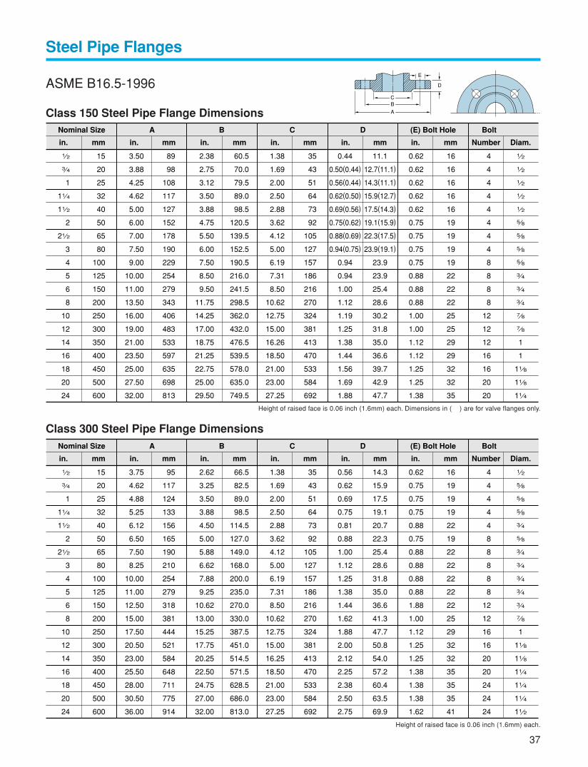
37
Steel Pipe Flanges
ASME B16.5-1996
Class 150 Steel Pipe Flange Dimensions
Class 300 Steel Pipe Flange Dimensions
Height of raised face is 0.06 inch (1.6mm) each. Dimensions in ( ) are for valve flanges only.
15
20
25
32
40
50
65
80
100
125
150
200
250
300
350
400
450
500
600
1 2
3 4
1
11 4
11 2
2
21 2
3
4
5
6
8
10
12
14
16
18
20
24
89
98
108
117
127
152
178
190
229
254
279
343
406
483
533
597
635
698
813
60.5
70.0
79.5
89.0
98.5
120.5
139.5
152.5
190.5
216.0
241.5
298.5
362.0
432.0
476.5
539.5
578.0
635.0
749.5
35
43
51
64
73
92
105
127
157
186
216
270
324
381
413
470
533
584
692
11.1
12.7(11.1)
14.3(11.1)
15.9(12.7)
17.5(14.3)
19.1(15.9)
22.3(17.5)
23.9(19.1)
23.9
23.9
25.4
28.6
30.2
31.8
35.0
36.6
39.7
42.9
47.7
16
16
16
16
16
19
19
19
19
22
22
22
25
25
29
29
32
32
35
4
4
4
4
4
4
4
4
8
8
8
8
12
12
12
16
16
20
20
1 2
1 2
1 2
1 2
1 2
5 8
5 8
5 8
5 8
3 4
3 4
3 4
7 8
7 8
1
1
11 8
11 8
11 4
Nominal Size
in. mm
A
mm
3.50
3.88
4.25
4.62
5.00
6.00
7.00
7.50
9.00
10.00
11.00
13.50
16.00
19.00
21.00
23.50
25.00
27.50
32.00
in.
2.38
2.75
3.12
3.50
3.88
4.75
5.50
6.00
7.50
8.50
9.50
11.75
14.25
17.00
18.75
21.25
22.75
25.00
29.50
in.
B
mm
C
mm
1.38
1.69
2.00
2.50
2.88
3.62
4.12
5.00
6.19
7.31
8.50
10.62
12.75
15.00
16.26
18.50
21.00
23.00
27.25
in.
D
mm
0.44
0.50(0.44)
0.56(0.44)
0.62(0.50)
0.69(0.56)
0.75(0.62)
0.88(0.69)
0.94(0.75)
0.94
0.94
1.00
1.12
1.19
1.25
1.38
1.44
1.56
1.69
1.88
in.
(E) Bolt Hole Bolt
mm
0.62
0.62
0.62
0.62
0.62
0.75
0.75
0.75
0.75
0.88
0.88
0.88
1.00
1.00
1.12
1.12
1.25
1.25
1.38
in. Number Diam.
15
20
25
32
40
50
65
80
100
125
150
200
250
300
350
400
450
500
600
1 2
3 4
1
11 4
11 2
2
21 2
3
4
5
6
8
10
12
14
16
18
20
24
95
117
124
133
156
165
190
210
254
279
318
381
444
521
584
648
711
775
914
66.5
82.5
89.0
98.5
114.5
127.0
149.0
168.0
200.0
235.0
270.0
330.0
387.5
451.0
514.5
571.5
628.5
686.0
813.0
35
43
51
64
73
92
105
127
157
186
216
270
324
381
413
470
533
584
692
14.3
15.9
17.5
19.1
20.7
22.3
25.4
28.6
31.8
35.0
36.6
41.3
47.7
50.8
54.0
57.2
60.4
63.5
69.9
16
19
19
19
22
19
22
22
22
22
22
25
29
32
32
35
35
35
41
4
4
4
4
4
8
8
8
8
8
12
12
16
16
20
20
24
24
24
1 2
5 8
5 8
5 8
3 4
5 8
3 4
3 4
3 4
3 4
3 4
7 8
1
11 8
11 8
11 4
11 4
11 4
11 2
Nominal Size
in. mm
A
mm
3.75
4.62
4.88
5.25
6.12
6.50
7.50
8.25
10.00
11.00
12.50
15.00
17.50
20.50
23.00
25.50
28.00
30.50
36.00
in.
2.62
3.25
3.50
3.88
4.50
5.00
5.88
6.62
7.88
9.25
10.62
13.00
15.25
17.75
20.25
22.50
24.75
27.00
32.00
in.
B
mm
C
mm
1.38
1.69
2.00
2.50
2.88
3.62
4.12
5.00
6.19
7.31
8.50
10.62
12.75
15.00
16.25
18.50
21.00
23.00
27.25
in.
D
mm
0.56
0.62
0.69
0.75
0.81
0.88
1.00
1.12
1.25
1.38
1.44
1.62
1.88
2.00
2.12
2.25
2.38
2.50
2.75
in.
(E) Bolt Hole Bolt
mm
0.62
0.75
0.75
0.75
0.88
0.75
0.88
0.88
0.88
0.88
1.88
1.00
1.12
1.25
1.25
1.38
1.38
1.38
1.62
in. Number Diam.
Height of raised face is 0.06 inch (1.6mm) each.
A
BC
E
D
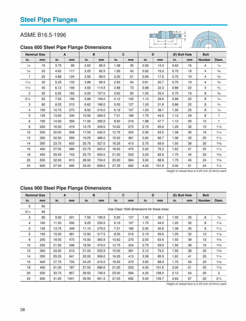
Steel Pipe Flanges
ASME B16.5-1996
Class 600 Steel Pipe Flange Dimensions
Class 900 Steel Pipe Flange Dimensions
Height of raised face is 0.25 inch (6.4mm) each.
Height of raised face is 0.25 inch (6.4mm) each.
15
20
25
32
40
50
65
80
100
125
150
200
250
300
350
400
450
500
600
1 2
3 4
1
11 4
11 2
2
21 2
3
4
5
6
8
10
12
14
16
18
20
24
95
117
124
133
156
165
190
210
273
330
356
419
508
559
603
686
743
813
940
66.5
82.5
89.0
98.5
114.5
127.0
149.0
168.0
216.0
266.5
292.0
349.0
432.0
489.0
527.0
603.0
654.0
724.0
838.0
35
43
51
64
73
92
105
127
157
186
216
270
324
381
413
470
533
584
692
14.3
15.9
17.5
20.7
22.3
25.4
28.6
31.8
38.1
44.5
47.7
55.6
63.5
66.7
69.9
76.2
82.6
88.9
101.6
16
19
19
19
22
19
22
22
25
29
29
32
35
35
38
41
45
45
51
4
4
4
4
4
8
8
8
8
8
12
12
16
20
20
20
20
24
24
1 2
5 8
5 8
5 8
3 4
5 8
3 4
3 4
7 8
1
1
11 8
11 4
11 4
13 8
11 2
15 8
15 8
17 8
Nominal Size
in. mm
A
mm
3.75
4.62
4.88
5.25
6.12
6.50
7.50
8.25
10.75
13.00
14.00
16.50
20.00
22.00
23.75
27.00
29.25
32.00
37.00
in.
2.62
3.25
3.50
3.88
4.50
5.00
5.88
6.62
8.50
10.50
11.50
13.75
17.00
19.25
20.75
23.75
25.75
28.50
33.00
in.
B
mm
C
mm
1.38
1.69
2.00
2.50
2.88
3.62
4.12
5.00
6.19
7.31
8.50
10.62
12.75
15.00
16.25
18.50
21.00
23.00
27.25
in.
D
mm
0.56
0.62
0.69
0.81
0.88
1.00
1.12
1.25
1.50
1.75
1.88
2.19
2.50
2.62
2.75
3.00
3.25
3.50
4.00
in.
(E) Bolt Hole Bolt
mm
0.62
0.75
0.75
0.75
0.88
0.75
0.88
0.88
1.00
1.12
1.12
1.25
1.38
1.38
1.50
1.62
1.75
1.75
2.00
in. Number Diam.
50
65
80
100
125
150
200
250
300
350
400
450
500
600
2
21 2
3
4
5
6
8
10
12
14
16
18
20
24
241
292
349
381
470
546
610
641
705
787
857
1041
190.5
235.0
279.5
317.5
393.5
470.0
533.5
559.0
616.0
686.6
749.5
901.5
127
157
186
216
270
324
381
413
470
533
584
692
38.1
44.5
50.8
55.6
63.5
69.9
79.2
85.9
88.9
101.6
108.0
139.7
25
32
35
32
38
38
38
41
45
51
54
67
8
8
8
12
12
16
20
20
20
20
20
20
7 8
11 8
11 4
11 8
13 8
13 8
13 8
11 2
15 8
17 8
2
21 2
Nominal Size
in. mm
A
mm
9.50
11.50
13.75
15.00
18.50
21.50
24.00
25.25
27.75
31.00
33.75
41.00
in.
7.50
9.25
11.10
12.50
15.50
18.50
21.00
22.00
24.25
27.00
29.50
35.50
in.
B
mm
C
Use Class 1500 dimensions for these sizes
mm
5.00
6.19
7.31
8.50
10.62
12.75
15.00
16.25
18.50
21.00
23.00
27.25
in.
D
mm
1.50
1.75
2.00
2.19
2.50
2.75
3.12
3.38
3.50
4.00
4.25
5.50
in.
(E) Bolt Hole Bolt
mm
1.00
1.25
1.38
1.25
1.50
1.50
1.50
1.62
1.75
2.00
2.12
2.62
in. Number Diam.
38
A
BC
E
D

Steel Pipe Flanges
ASME B16.5-1996
Class 1500 Steel Pipe Flange Dimensions
Height of raised face is 0.06 inch (1.6mm) each.
Height of raised face is 0.25 inch (6.4mm) each.
50
65
80
100
125
150
200
250
300
350
400
450
500
600
2
21 2
3
4
5
6
8
10
12
14
16
18
20
24
216
244
267
311
375
394
483
584
673
749
826
914
984
1168
165.0
190.5
203.0
241.5
292.0
317.5
393.5
482.5
571.5
635.0
705.0
774.5
832.0
990.5
92
105
127
157
186
216
270
324
381
413
470
533
584
692
38.1
41.2
47.8
53.9
73.2
82.6
92.0
108.0
124.0
133.4
146.1
162.1
177.8
203.2
25
29
32
35
41
38
45
51
54
60
67
73
79
92
8
8
8
8
8
12
12
12
16
16
16
16
16
16
7 8
1
11 8
11 4
11 2
13 8
15 8
17 8
2
21 4
21 2
21 2
3
31 2
Nominal Size
in. mm
A
mm
8.50
9.62
10.50
12.25
14.75
15.50
19.00
23.00
26.50
29.50
32.50
36.00
38.75
46.00
in.
6.50
7.50
8.00
9.50
11.50
12.50
15.50
19.00
22.50
25.00
27.75
30.50
32.75
39.00
in.
B
mm
C
mm
3.62
4.12
5.00
6.19
7.31
8.50
10.62
12.75
15.00
16.25
18.50
21.00
23.00
27.25
in.
D
mm
1.50
1.62
1.88
2.12
2.88
3.25
3.62
4.25
4.88
5.25
5.75
6.38
7.00
8.00
in.
(E) Bolt Hole Bolt
mm
1.00
1.12
1.25
1.38
1.62
1.50
1.75
2.00
2.12
2.38
2.62
2.88
3.12
3.62
in. Number Diam.
MSS SP-44-1996
Class 150 and 300 Steel Pipe Flange Dimensions
550
550
22
22
150
300
749
838
692
743
641
641
46.0
66.5
35
41
20
24
11 4
11 2
Nominal SizeClass
in. mm
A
mm
29.50
33.00
in.
27.25
29.25
in.
B
mm
C
mm
25.25
25.25
in.
D
mm
1.81
2.62
in.
(E) Bolt Hole Bolt
mm
1.38
1.62
in. Number Diam.
39
A
BC
E
D
A
BC
E
D
Care for Handling Valves
1. Before mounting valves:
Before mounting valves, be sure that adequate valveshave been prepared to exactly meet the service con-ditions including the maximum design pressures andtemperatures. Foreign objects such as sands or scalesmay be left in the pipes, and care should be taken toremove all of them by filters or strainers to protectvalves seat surfaces during subsequent valve com-missioning.
2. Mounting valves:
On mounting valves, clean the inside of pipes againso that no welding spatters, chips, scales or sandsare left. For installation of flanged end valves, flangebolts should be tigthened alternately and diagonally.Where extraordinary external forces such as pipingstress may be applied to the flanges of valves beingmounted,provide valve supports or any otheradequeate protective measures. For socket weldingworks, refer to Page 31 of this catalog.
3. Retightening valves glands:
When leakage is detected from the gland area whilethe valve is being in service, the gland should beimmediately retightened. Tighten the gland slowlyand gradually until the leakage stops,while rotatingthe valve handwheel. In case the valve operatingtorque has been found considerably increased afterthese procedures, it is recommended to replace allpacking rings at the time of valve maintenance.
4. Replacing packing rings:
It is recommended to replace packing rings duringvalve maintenance operation, but never while the valveis being pressurized in service, except the line pres-sure is reduced to the atmospheric level. KITZ stain-less steel valves (Series A, AJ, C and D) are pro-vided with the backseats or bonnet bushes. If leak-age from the gland area cannot be stopped by re-tightening the gland, operate the valve to its full openposition and add a few packing rings or replace pack-ing rings utilizing sealing function of these backseats.
Sealing function of backseats is sometimes disturbeddue to rust or other foreign objects trapped inside. Itshould be carefully checked before adding or replac-ing packing rings that backseats function properly.When the valve is highly pressurized, it sometimescauses danger to replace all of packing rings. In thiscase, adding a few new rings or replacing a few ringson top of the packing chamber is recommended asa first aid solution.
For replacement of packing rings, first remove thegland bolts and then packing rings. Clean the pack-ing chamber and the valve stem. After checking thatall sliding parts are in good condition, securely installnew packing rings. Press new packing rings ligtly afew times with the gland and then evenly tighten thegland.
All KITZ stainless and high alloy steel valves are guar-anteed for 12 months after placement in service, butnot exceeding 18 months after shipment from the fac-tories of KITZ Corporation, provided that the valvesare properly handled according to the relevant KITZoperation manual.
40
KITZ Protect Warranty
1-10-1, Nakase, Mihama-ku, Chiba 261-8577, JapanInternational Sales Dept. Phone: 81-43-299-1730, 1732 and 1733
Fax: 81-43-299-0121
Distributed by
Pressure-temperature ratings and other performance data publishedin this catalog have been developed from our design calculation,in-house testing, field reports provided by our customers and/orpublished official standards or specifications. They are good only tocover typical applications as a general guideline to users of KITZproducts introduced in this catalog.
For any specific application, users are kindly requested to contactKITZ Corporation for technical advice, or to carry out their own studyand evaluation for proving suitability of these products to such anapplication. Failure to follow this request could result in propertydamage and/or personal injury, for which we shall not be liable.
While this catalog has been compiled with the utmost care, we as-sume no responsibility for errors, impropriety or inadequacy. Anyinformation provided in this catalog is subject to from-time-to-timechange without notice for error rectification, product discontinua-tion, design modification, new product introduction or any othercause that KITZ Corporation considers necessary. This edition can-cels all previous issues.
0005①ITPPrinted in Japan
CAUTION
10750 Corporate Drive, Stafford, Texas 77477, U.S.APhone: 281-491-7333 Fax:281-491-9402