Embed Size (px)
Citation preview
explosion protectionThe basics of
preface
It is a fact that gases, vapours and mists escape during the production, processing,
transportation and storage of flammable substances in the chemical and petrochemical
industries, as well as in the production of mineral oil and natural gas, in mining and in
many other sectors. During many processes, especially in food industries, combustible
dusts are also created. These flammable gases, vapours, mists, and dusts form an explosive
atmosphere with the oxygen in the air. If this atmosphere is ignited, explosions take place,
which can result in severe harm to human life and property. To avoid the danger of
explosions, protective specifications in the form of laws, regulations, and standards have
been developed in most countries, which are aimed at ensuring that a high level of safety is
observed. Due to the growing international economic link, extensive progress has
been made in harmonizing regulations for explosion protection. The conditions for a
complete harmonization were created in the European Union by the 94/9/EC and 99/92/EC
Directives. However, there is still much to be done in this area world-wide. The aim of
this brochure is to provide both experts and interested laymen with an overview of the field
of explosion protection, in conjunction with electrical apparatus and installations. It does
not replace the study of the relevant statutory regulations and applicable standards.
In mining, miners underground have always lived under the threat of firedamp explosions.
Herein lies the origins of explosion protection, which has been consistently developed
in industrialized countries, and which now provides a high level of safety.
R. STAHL explosion protection
R. STAHL explosion protection
2
6
9
9
9
9
13
14
16
16
16
18
19
24
25
27
28
28
28
29
30
contents
123
4
5
Preface
The Basic Physic Principles and Definitions of Explosion Protection
Statutory Regulations and Standards
3.1 Introduction
3.2 European Directives
3.2.1 The Directive 94/9/EC (ATEX 95)
3.2.2 The Directive 99/92/EC (ATEX 137)
3.3 Standards
Technical Principles
4.1 Zone Classification
4.2 Minimum Ignition Energy and Explosion Group
4.3 Minimum Ignition Temperature and Temperature Classes
4.4 Types of Protection
4.4.1 Application and Combination of Types of Protection “d” and “e”
4.4.2 Applications of Type of Protection “Intrinsic Safety”
4.4.3 Applications of Type of Protection “c”
Installation and Operation of Electrical Equipment in Hazardous Locations
5.1 Duties of Installer, Manufacturer and Operator
5.2 Classification of Zones and Selection of Apparatus
5.3 Methods of Installation
5.4 Maintenance
R. STAHL explosion protection
31
31
31
32
32
32
33
34
34
36
37
38
40
41
42
44
6
7
8
Explosion Protection in North America
6.1 Introduction
6.2 Classification of Hazardous Locations
6.3 Regulations for Installation
6.4 Constructional Requirements
6.5 Degrees of Protection provided by Enclosures
6.6 Certification and Marking
Appendix
7.1 Comparison of IEC Publications and European Standards (EN)
7.2 Safety Ratings of Flammable Gases and Vapours
7.3 Classification of Hazardous Locations in North America
7.4 Constructional Requirements for Explosion Protected Electrical Equipment
7.5 Degrees of Protection according to IEC 60 529 – IPXX
7.6 Degrees of Protection according to NEMA Standards
Literature
Adresses9
2. the basic physic principles and definitions6
explosion protection
2. The Basic Physic Principles and Definitionsof Explosion Protection
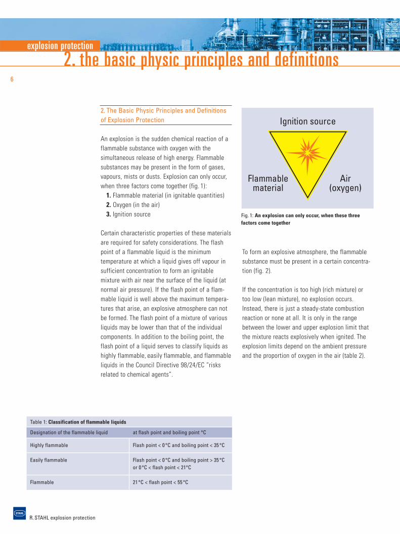
An explosion is the sudden chemical reaction of aflammable substance with oxygen with the simultaneous release of high energy. Flammablesubstances may be present in the form of gases,vapours, mists or dusts. Explosion can only occur,when three factors come together (fig. 1):
1. Flammable material (in ignitable quantities)2. Oxygen (in the air)3. Ignition source
Certain characteristic properties of these materialsare required for safety considerations. The flashpoint of a flammable liquid is the minimum temperature at which a liquid gives off vapour in sufficient concentration to form an ignitable mixture with air near the surface of the liquid (atnormal air pressure). If the flash point of a flam-mable liquid is well above the maximum tempera-tures that arise, an explosive atmosphere can not be formed. The flash point of a mixture of various liquids may be lower than that of the individualcomponents. In addition to the boiling point, theflash point of a liquid serves to classify liquids ashighly flammable, easily flammable, and flammableliquids in the Council Directive 98/24/EC “risksrelated to chemical agents”.
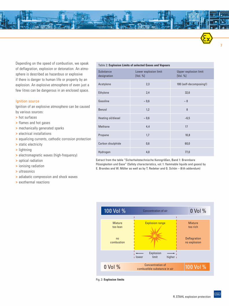
To form an explosive atmosphere, the flammablesubstance must be present in a certain concentra-tion (fig. 2).
If the concentration is too high (rich mixture) ortoo low (lean mixture), no explosion occurs.Instead, there is just a steady-state combustionreaction or none at all. It is only in the rangebetween the lower and upper explosion limit thatthe mixture reacts explosively when ignited. Theexplosion limits depend on the ambient pressureand the proportion of oxygen in the air (table 2).
Fig. 1: An explosion can only occur, when these threefactors come together
Table 1: Classification of flammable liquids
Designation of the flammable liquid at flash point and boiling point °C
Highly flammable Flash point < 0 °C and boiling point < 35 °C
Easily flammable Flash point < 0 °C and boiling point > 35 °Cor 0 °C < flash point < 21°C
Flammable 21 °C < flash point < 55 °C
R. STAHL explosion protection
7
Depending on the speed of combustion, we speakof deflagration, explosion or detonation. An atmo-sphere is described as hazardous or explosive if there is danger to human life or property by anexplosion. An explosive atmosphere of even just afew litres can be dangerous in an enclosed space.
Ignition sourceIgnition of an explosive atmosphere can be causedby various sources:> hot surfaces> flames and hot gases> mechanically generated sparks> electrical installations> equalizing currents, cathodic corrosion protection> static electricity> lightning> electromagnetic waves (high-frequency)> optical radiation> ionising radiation> ultrasonics> adiabatic compression and shock waves> exothermal reactions
Table 2: Explosion Limits of selected Gases and Vapours
Substance Lower explosion limit Upper explosion limit designation [Vol. %] [Vol. %]
Acetylene 2,3 100 (self-decomposing!)
Ethylene 2,4 32,6
Gasoline ~ 0,6 ~ 8
Benzol 1,2 8
Heating oil/diesel ~ 0,6 ~6,5
Methane 4,4 17
Propane 1,7 10,8
Carbon disulphide 0,6 60,0
Hydrogen 4,0 77,0
Mixturetoo lean
nocombustion
Mixturetoo rich
Deflagrationno explosion
Explosion range
Explosionlower limit higher
Concentration of air100 Vol % 0 Vol %
Concentration ofcombustible substance in air0 Vol % 100 Vol %
Fig. 2: Explosion limits
Extract from the table “Sicherheitstechnische Kenngrößen, Band 1: Brennbare Flüssigkeiten und Gase” (Safety characteristics, vol. 1: flammable liquids and gases) by E. Brandes and W. Möller as well as by T. Redeker and G. Schön – (6 th addendum)
R. STAHL explosion protection
2. the basic physic principles and definitions8
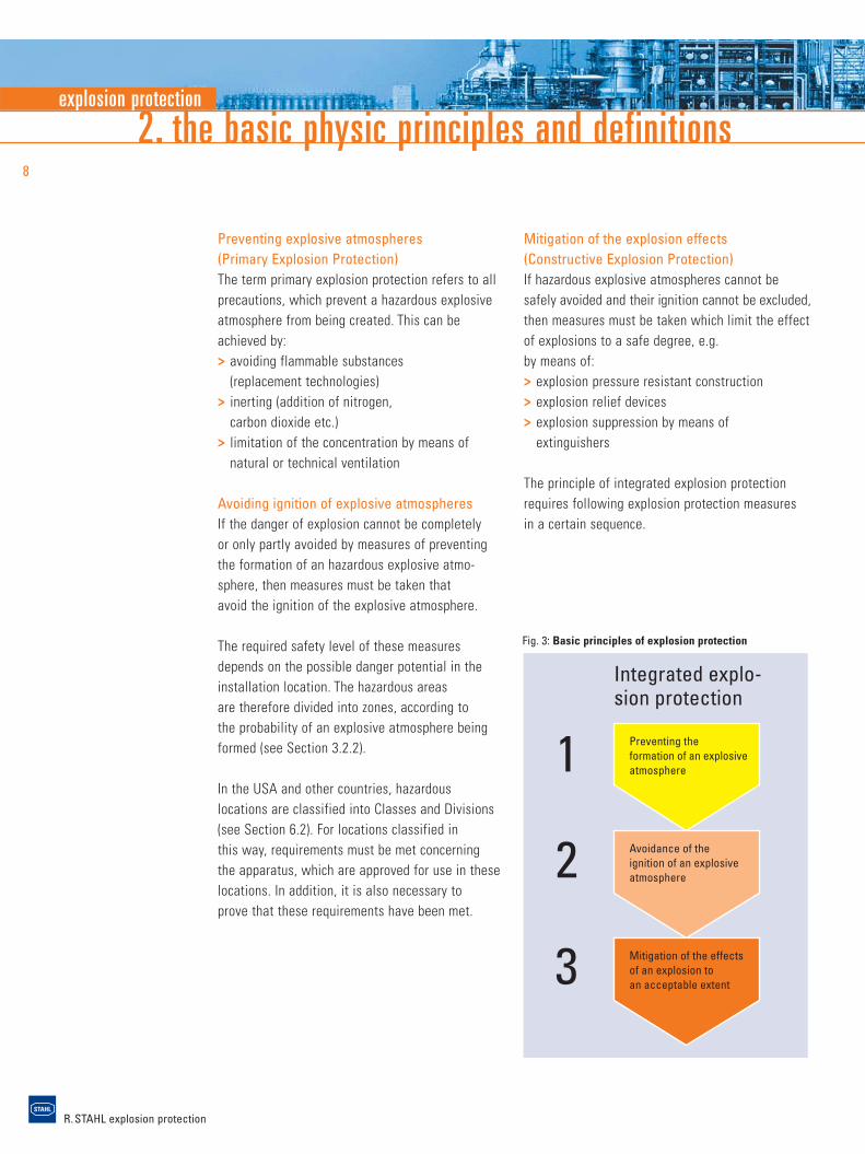
Mitigation of the explosion effects(Constructive Explosion Protection)If hazardous explosive atmospheres cannot be safely avoided and their ignition cannot be excluded,then measures must be taken which limit the effectof explosions to a safe degree, e.g. by means of:> explosion pressure resistant construction> explosion relief devices> explosion suppression by means of
extinguishers
The principle of integrated explosion protectionrequires following explosion protection measures in a certain sequence.
1
2
3
Preventing theformation of an explosiveatmosphere
Avoidance of theignition of an explosiveatmosphere
Mitigation of the effectsof an explosion toan acceptable extent
Integrated explo-sion protection
Preventing explosive atmospheres(Primary Explosion Protection)The term primary explosion protection refers to allprecautions, which prevent a hazardous explosiveatmosphere from being created. This can beachieved by:> avoiding flammable substances
(replacement technologies)> inerting (addition of nitrogen,
carbon dioxide etc.)> limitation of the concentration by means of
natural or technical ventilation
Avoiding ignition of explosive atmospheresIf the danger of explosion cannot be completely or only partly avoided by measures of preventingthe formation of an hazardous explosive atmo-sphere, then measures must be taken that avoid the ignition of the explosive atmosphere.
The required safety level of these measuresdepends on the possible danger potential in theinstallation location. The hazardous areas are therefore divided into zones, according to the probability of an explosive atmosphere beingformed (see Section 3.2.2).
In the USA and other countries, hazardous locations are classified into Classes and Divisions(see Section 6.2). For locations classified in this way, requirements must be met concerningthe apparatus, which are approved for use in theselocations. In addition, it is also necessary to prove that these requirements have been met.
Fig. 3: Basic principles of explosion protection
explosion protection
R. STAHL explosion protection
9
3. statutory regulations and standards
3. Statutory Regulations
3.1 Introduction
Areas in which there is a risk of explosion thatmay harm people or the environment are subjectto legal or comparable rules in most countries of the world. While these rules were initiallyissued at the national level, they have since beenreplaced over the last years by regional EuropeanDirectives and Standards, and in the field of standardization they have partially been replacedby international regulations.
3.2 European Directives
Already in 1976, the Council of the EuropeanCommunity established the prerequisite of free trade of explosion protected electrical equip-ment within the European Union by ratifying the “Directive on the harmonization of the laws of the member states concerning electrical equipment for use in potentially explosive atmo-spheres (76/117/EEC)”. This directive has sincebeen adapted to the state of the art by means ofexecution and adaptation directives on electrical equipment.
Complete harmonization and extension to all typesof equipment was achieved with the new Directive 94/9/EC in 1994. The Directive 99/92/EC, which regulates operation in hazardous areas and defines safety measures for the concernedpersonnel, was issued in 1999.
3.2.1 The Directive 94/9/EC (ATEX 95)
The EC Directive 94/9/EC “on the approximation ofthe laws of the Member States concerning equip-
ment and protective systems intended for use in potentially explosive atmospheres” was issuedin 1994 to further standardize explosion protectionand make corresponding adjustments in line witha new directive approach. It specifies the require-ments for explosion protected equipment and protective systems by prescribing essential healthand safety requirements. It guarantees free trade within the European Community, as agreedin Article 95 (former 100 a) of the Treaty established between the European Communitymember states. This is also where the term generally used amongst experts, ATEX 95 or 100 a,comes from. This term is the abbreviation of the French designation for explosive atmosphere“atmosphères explosibles”.
The directive had to be implemented into nationallaw without any changes/exceptions. E.g. it was adopted into british law by means of TheEquipment and Protective Systems for Use in Potentially Explosive Atmospheres Regulations(EPS) and into German law by means of the“Explosionsschutzverordnung (ExVO)” (Regulationof Explosion Protection) as the 11th Regulation ofthe “Geräte- und Produktsicherkeitsgesetz (GPSG)”(Equipment and Product Safety Law).
The directive applies to all industrial potentiallyexplosive areas including mining, and also coversdust explosion protection. The scope covers all electrical and non-electrical equipment, and protective systems.
This directive is intended for the manufacturer or the importer, and defines design, certification, production and quality assurance, marking, operating instructions, and declaration of conform-ity for the explosion protected equipment to beplaced on the market.
R. STAHL explosion protection
3. statutory regulations and standards10
or dusts in which, after ignition has occurred,combustion spreads to the entire unburned mixture.
> A “potentially explosive atmosphere” is anatmosphere which could become explosive dueto local and operational conditions.
ScopeThe directive applies to equipment and pro- tective systems for use in potentially explosiveatmospheres.
Safety devices intended for use outside potentiallyexplosive atmospheres but required for or con-tributing to the safe functioning of equipment withrespect to the risk of explosion are also covered by the scope of this Directive. The Directive doesnot include a reference to mandatory standards,whereas it specifies the essential health and safety requirements to be maintained, and whichare mandatory for design and construction.Protection against other hazards (e.g. electricshock) that could be caused by this equipment, is also required as well.
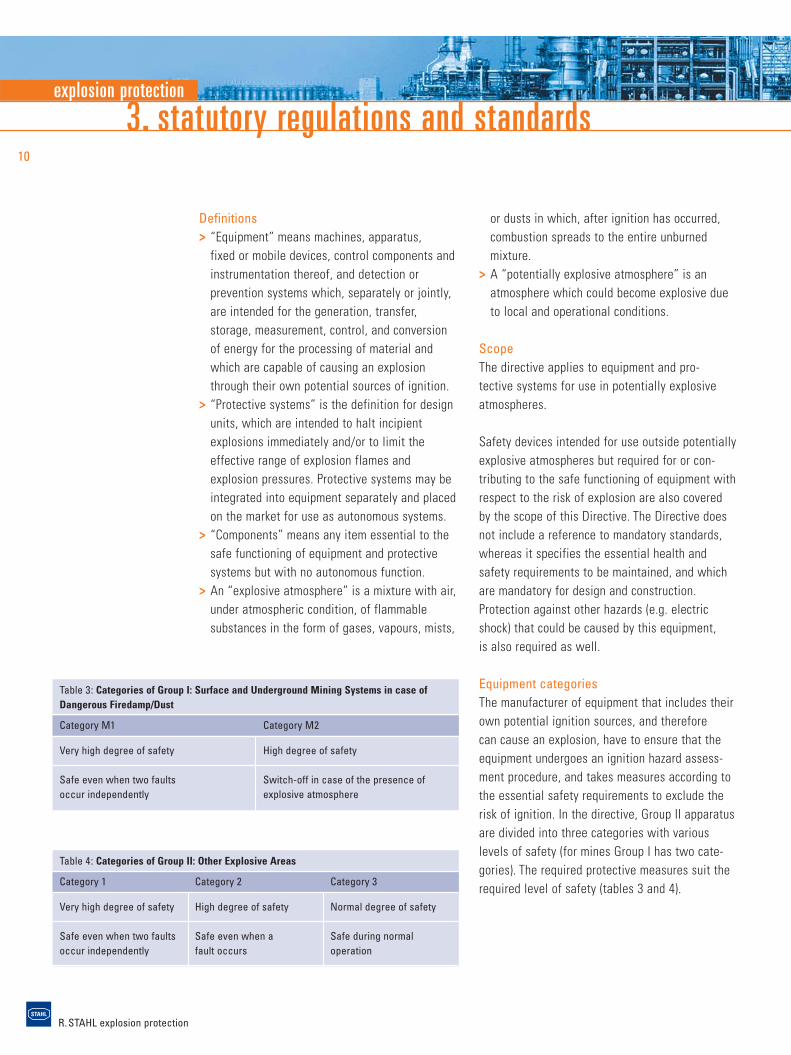
Equipment categoriesThe manufacturer of equipment that includes theirown potential ignition sources, and therefore can cause an explosion, have to ensure that theequipment undergoes an ignition hazard assess-ment procedure, and takes measures according tothe essential safety requirements to exclude therisk of ignition. In the directive, Group II apparatusare divided into three categories with various levels of safety (for mines Group I has two cate-gories). The required protective measures suit the required level of safety (tables 3 and 4).
Definitions> “Equipment” means machines, apparatus,
fixed or mobile devices, control components andinstrumentation thereof, and detection or prevention systems which, separately or jointly,are intended for the generation, transfer, storage, measurement, control, and conversionof energy for the processing of material andwhich are capable of causing an explosionthrough their own potential sources of ignition.
> “Protective systems” is the definition for designunits, which are intended to halt incipient explosions immediately and/or to limit theeffective range of explosion flames and explosion pressures. Protective systems may beintegrated into equipment separately and placed on the market for use as autonomous systems.
> “Components” means any item essential to thesafe functioning of equipment and protectivesystems but with no autonomous function.
> An “explosive atmosphere” is a mixture with air,under atmospheric condition, of flammable substances in the form of gases, vapours, mists,
Table 3: Categories of Group I: Surface and Underground Mining Systems in case ofDangerous Firedamp/Dust
Category M1 Category M2
Very high degree of safety High degree of safety
Safe even when two faults Switch-off in case of the presence ofoccur independently explosive atmosphere
Table 4: Categories of Group II: Other Explosive Areas
Category 1 Category 2 Category 3
Very high degree of safety High degree of safety Normal degree of safety
Safe even when two faults Safe even when a Safe during normal occur independently fault occurs operation
explosion protection
R. STAHL explosion protection
11
CertificationEquipment for use in hazardous areas has toundergo the conformity assessment proceduredefined in the directive prior to being placed onthe market. Category 1 and M1 equipment mustundergo an EC type examination carried out by aNotified Body. The same applies to electricalequipment and I.C.-engines of Category 2 and M2. For non-electrical equipment of this category, as well as for those of Category 3, the manufac-turer is authorized to assess and document conformity with the requirements of the directive.
The certificates from a Notified Body are recog-nized throughout the European Community.
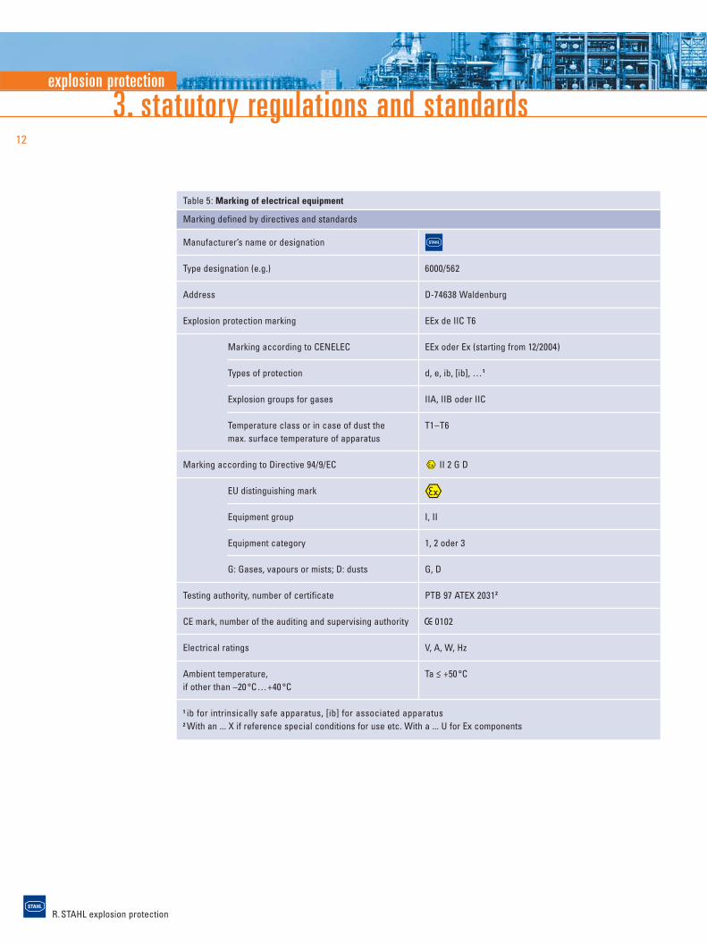
MarkingIn addition to the usual data such as the name of the manufacturer, type, serial number, and electrical ratings, any data relating to explosionprotection must be contained in the marking(see table 5, marking according to the 94/9/ECDirective and the standards EN 60079 ff and EN61241 ff).
The CE marking of the equipment confirms that itis designed and manufactured in compliance withall applicable EC Directives. For example, anexplosion protected luminaire marked with the CEconformity mark must comply with both the ATEX Directive as well as the “EMC Directive”.
Operating instructionsThe operating instructions of the manufacturermust clearly define the intended use of the equipment by the operator. The minimum requirements for the operating instruction areamongst others:Information on safe> putting into service> use> assembling and dismantling> maintenance (servicing and emergency repair)> installation> adjustment
If necessary, special conditions for safe use have to be specified and should include notes on possible misuse that may occur as experience hasshown.
Manufacturer’s Declaration of ConformityEquipment and systems can be placed on the market, only if marked with the CE mark and com-plete with operating instructions and the manufac-turer’s declaration of conformity. The CE conformity marking and the written declaration of conformityconfirm that the product complies with all require-ments and assessment procedures specified in the EC Directives.
R. STAHL explosion protection
3. statutory regulations and standards12
Table 5: Marking of electrical equipment
Marking defined by directives and standards
Manufacturer’s name or designation
Type designation (e.g.) 6000/562
Address D-74638 Waldenburg
Explosion protection marking EEx de IIC T6
Marking according to CENELEC EEx oder Ex (starting from 12/2004)
Types of protection d, e, ib, [ib], …1
Explosion groups for gases IIA, IIB oder IIC
Temperature class or in case of dust the T1–T6max. surface temperature of apparatus
Marking according to Directive 94/9/EC II 2 G D
EU distinguishing mark
Equipment group I, II
Equipment category 1, 2 oder 3
G: Gases, vapours or mists; D: dusts G, D
Testing authority, number of certificate PTB 97 ATEX 20312
CE mark, number of the auditing and supervising authority 0102
Electrical ratings V, A, W, Hz
Ambient temperature, Ta < +50 °Cif other than –20 °C…+40 °C
1 ib for intrinsically safe apparatus, [ib] for associated apparatus2 With an ... X if reference special conditions for use etc. With a ... U for Ex components
explosion protection
R. STAHL explosion protection
13
Assessment of explosion risksWhen assessing the risks of explosion, the following factors are to be taken into account:> the likelihood that explosive atmospheres
will occur and their persistence> the likelihood that ignition sources, including
electrostatic discharges, will be present and become active and effective
> the installations, substances used, processes,and their possible interactions
> the scale of the anticipated effects
Zone ClassificationThe employer has to classify the areas in whichexplosive atmospheres may be present into zones,and to ensure that the minimum organisationaland technical requirements of the Directive areobserved.
Zone 0A place in which an explosive atmosphere con-sisting of a mixture with air of flammable substances in the form of gas, vapour or mist ispresent continuously or for long periods or frequently.
Zone 1A place in which an explosive atmosphere con-sisting of a mixture with air or flammable substances in the form of gas, vapour or mist islikely to occur in normal operation occasionally.
Zone 2A place in which an explosive atmosphere con-sisting of a mixture with air of flammable substances in the form of gas, vapour or mist isnot likely to occur in normal operation but, if it does occur, will persist for a short period only.
3.2.2 The Directive 99/92/EC
In addition to the 94/9/EC Directive, which regulates how explosion protected equipment andprotective systems are placed on the market and the design, construction and quality require-ments to be met by them, the 99/92/EC Directivestating “Minimum requirements for improving thehealth and safety protection of worker potentiallyat risk from explosive atmospheres” refers to the operation of potentially explosive installations,and is therefore intended for the employer. Thisdirective contains only minimum requirements.When implementing it into national law, the singlestates can adopt further regulations. This wasdone when implementing it into British law by“The Dangerous Substances and Explosive Atmo-spheres Regulations (DSEAR)” and into Germanlaw by the “Betriebssicherheitsverordnung(BetrSichV)”, the German regulation on IndustrialSafety and Health Protection, which in addition to this directive, takes into consideration furtherEuropean directives on safety on work.Comparable regulations are found in otherEuropean countries.
According to the 99/92/EC Directive, it is the duty of the employer to verify where there is a risk of explosion, classify the hazardous areas intozones accordingly, and document all measurestaken to protect the personnel in the explosionprotection document.
R. STAHL explosion protection
3. statutory regulations and standards14
Zone 20A place in which an explosive atmosphere in the form of a cloud of combustable dust in air is present continously, or for long periods or frequently.
Zone 21A place in which an explosive atmosphere in theform of a cloud of combustible dust in air is likely to occur in normal operation occasionally.
Zone 22A place in which an explosive atmosphere in theform of a cloud of combustible dust in air is not likely to occur in normal operation but, if itdoes occur, will persist for a short period only.
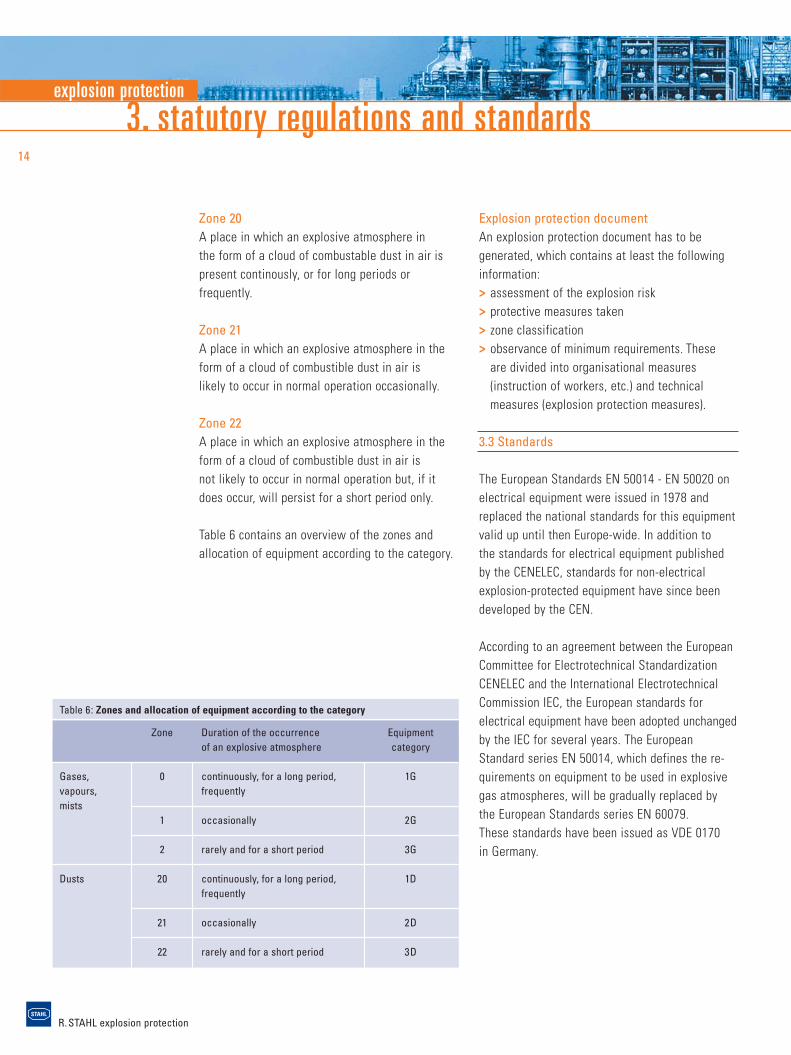
Table 6 contains an overview of the zones andallocation of equipment according to the category.
Explosion protection documentAn explosion protection document has to be generated, which contains at least the followinginformation:> assessment of the explosion risk> protective measures taken> zone classification> observance of minimum requirements. These
are divided into organisational measures(instruction of workers, etc.) and technical measures (explosion protection measures).
3.3 Standards
The European Standards EN 50014 - EN 50020 onelectrical equipment were issued in 1978 and replaced the national standards for this equipmentvalid up until then Europe-wide. In addition to the standards for electrical equipment publishedby the CENELEC, standards for non-electrical explosion-protected equipment have since been developed by the CEN.
According to an agreement between the EuropeanCommittee for Electrotechnical StandardizationCENELEC and the International ElectrotechnicalCommission IEC, the European standards for electrical equipment have been adopted unchangedby the IEC for several years. The EuropeanStandard series EN 50014, which defines the re-quirements on equipment to be used in explosivegas atmospheres, will be gradually replaced by the European Standards series EN 60079. These standards have been issued as VDE 0170 in Germany.
Table 6: Zones and allocation of equipment according to the category
Zone Duration of the occurrence Equipmentof an explosive atmosphere category
Gases, 0 continuously, for a long period, 1Gvapours, frequentlymists
1 occasionally 2G
2 rarely and for a short period 3G
Dusts 20 continuously, for a long period, 1Dfrequently
21 occasionally 2D
22 rarely and for a short period 3D
explosion protection
R. STAHL explosion protection
15
Table 7: Electrical Apparatus for Explosive Gas Atmospheres
EN (old) EN (new) IEC
General requirements EN 50 014 EN 60079-0 IEC 60079-0
Flameproof enclosures “d” EN 50 018 EN 60079-1 IEC 60079-1
Pressurized enclosures “p” EN 50 016 EN 60079-2 IEC 60079-2
Powder filling “q” EN 50 017 EN 60079-5 IEC 60079-5
Oil immersion “o” EN 50 015 EN 60079-6 IEC 60079-6
Increased safety “e" EN 50 019 EN 60079-7 IEC 60079-7
Intrinsic safety “i” EN 50 020 EN 60079-11 IEC 60079-11
Type of protection “n” EN 50 021 EN 60079-15 IEC 60079-15
Encapsulation “m” EN 50 028 EN 60079-18 IEC 60079-18
Intrinsically safe systems EN 60079-25 IEC 60079-25
Electrical equipment for Zone 0 EN 50 284 EN 60079-26 IEC 60079-26
Intrinsically safe field bus systems EN 60079-27 IEC 60079-27
Optical radiation “op” EN 60079-28 IEC 60079-28
Table 8: Electrical Apparatus for Use in the Presence of Combustible Dust
EN (old) EN (new) IEC (new) IEC (old)
General requirements EN 61241-0 IEC 61241-0 IEC 61241-1-1
Protected by enclosures “tD” EN 50281-1-1 EN 61241-1 IEC 61241-1 IEC 61241-1-1
Pressurized enclosures “pD” EN 61241-2 EN 61241-2 EN 61241-4
Intrinsic safety “iD” EN 61241-11 IEC 61241-11 EN 61241-5
Encapsulation “mD” EN 61241-18 IEC 61241-18
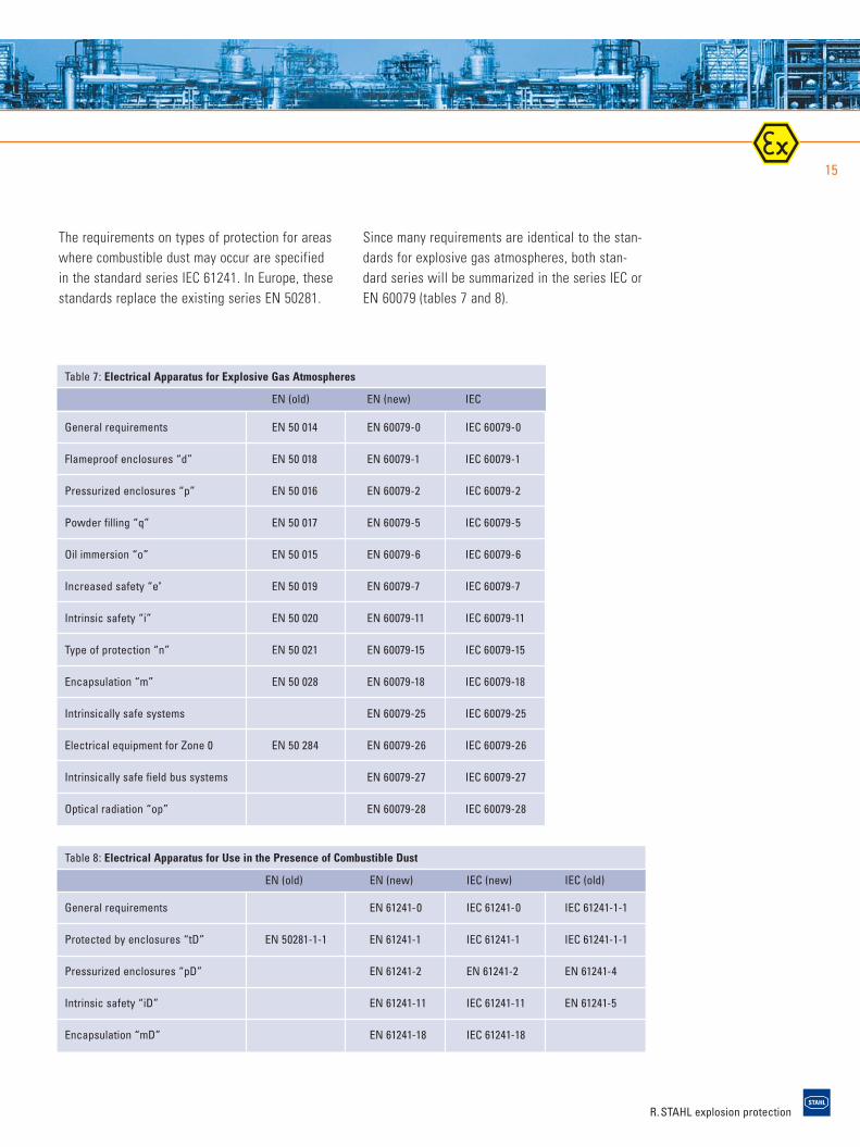
The requirements on types of protection for areaswhere combustible dust may occur are specified in the standard series IEC 61241. In Europe, thesestandards replace the existing series EN 50281.
Since many requirements are identical to the stan-dards for explosive gas atmospheres, both stan-dard series will be summarized in the series IEC orEN 60079 (tables 7 and 8).
R. STAHL explosion protection
4. technical principles16
4. Technical Principles
4.1 Zone Classification
Hazardous areas are classified into zones to facili-tate the selection of appropriate electrical appa-ratus as well as the design of suitable electricalinstallations. Information and specifications for the classification into zones are included in IEC60079-10.
The greatest potential risk has to be taken intoaccount when classifying the potentially explosiveareas into zones and determining the necessaryprotective measures.
If there is no expert (skilled person) available inthe company to verify the risk of explosion and todetermine the necessary measures, it is recom-mended that a competent authority be turned to.
The equipment used in the defined hazardous zone must meet the requirements of the relevantassigned category (see section 3.2.1).
4.2 Minimum Ignition Energy and Explosion Group
The minimum ignition energy is the minimum energy just sufficient to ignite the most ignitablemixture. This characteristic has to be consideredwhen selecting the apparatus. The measured value of the minimum ignition energy is indicatedfor dusts. Gases are divided into explosion groups.
Explosion groups Apparatus are divided into two groups:> Group I:
Electrical apparatus for mines endangered by firedamp
> Group II:Electrical apparatus for other places liable to be endangered by explosive atmospheres
In the case of electrical apparatus in Group I (mining), it is assumed that the only flammable gas that can occur is methane, but combined with coal dust. Other flammable gases, which canalso occur in these areas, must be further classified as shown in Group II.
Electrical apparatus of Group II used in explosivegas atmospheres are further classified into explosion groups.
explosion protection
R. STAHL explosion protection
17
Table 9: Explosion Groups
Explosion group Maximum experimental safe gap Minimum ignition current ratio*
IIA > 0,9 > 0,8
IIB 0,5 – 0,9 0,45 – 0,8
IIC < 0,5 < 0,45
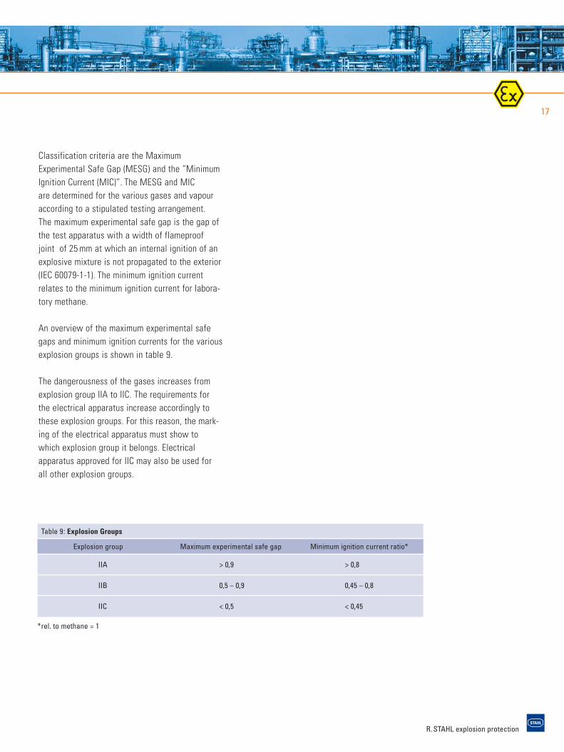
Classification criteria are the MaximumExperimental Safe Gap (MESG) and the “MinimumIgnition Current (MIC)”. The MESG and MIC are determined for the various gases and vapouraccording to a stipulated testing arrangement.The maximum experimental safe gap is the gap ofthe test apparatus with a width of flameproof joint of 25 mm at which an internal ignition of anexplosive mixture is not propagated to the exterior(IEC 60079-1-1). The minimum ignition currentrelates to the minimum ignition current for labora-tory methane.
An overview of the maximum experimental safegaps and minimum ignition currents for the variousexplosion groups is shown in table 9.
The dangerousness of the gases increases fromexplosion group IIA to IIC. The requirements forthe electrical apparatus increase accordingly tothese explosion groups. For this reason, the mark-ing of the electrical apparatus must show towhich explosion group it belongs. Electrical apparatus approved for IIC may also be used forall other explosion groups.
*rel. to methane = 1
R. STAHL explosion protection
4. technical principles18
4.3 Ignition Temperature and Temperature classes
The ignition temperature of a flammable gas,vapour, or combustible dust is the lowest temper-ature of a heated surface at which the gas/air orvapour/air mixture ignites. It represents virtuallythe lowest temperature at which a hot surface canignite a respective explosive atmosphere.
Flammable gases and vapours are classified intotemperature classes according to their inflamma-bility. The maximum surface temperature of elec-trical apparatus should always be lower than theignition temperature of the gas/air or vapour/airmixture in which it is used. Of course, equipmentclassified in a higher temperature class (e.g. T5)may also be used for applications in which a lowertemperature class is required (e.g. T2 or T3).In North America there is a system incorporatingfurther classification according to temperaturesubclasses.
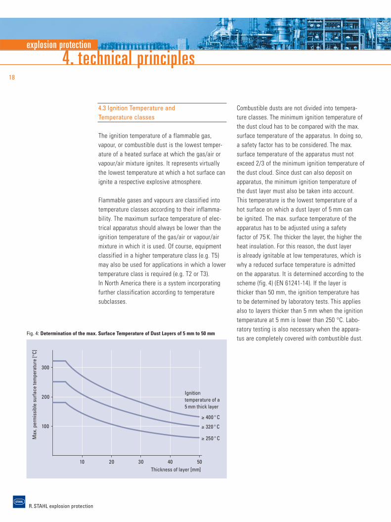
Combustible dusts are not divided into tempera-ture classes. The minimum ignition temperature ofthe dust cloud has to be compared with the max.surface temperature of the apparatus. In doing so,a safety factor has to be considered. The max. surface temperature of the apparatus must notexceed 2/3 of the minimum ignition temperature ofthe dust cloud. Since dust can also deposit onapparatus, the minimum ignition temperature ofthe dust layer must also be taken into account.This temperature is the lowest temperature of ahot surface on which a dust layer of 5 mm can be ignited. The max. surface temperature of theapparatus has to be adjusted using a safety factor of 75 K. The thicker the layer, the higher theheat insulation. For this reason, the dust layer is already ignitable at low temperatures, which iswhy a reduced surface temperature is admitted on the apparatus. It is determined according to thescheme (fig. 4) (EN 61241-14). If the layer is thicker than 50 mm, the ignition temperature hasto be determined by laboratory tests. This appliesalso to layers thicker than 5 mm when the ignitiontemperature at 5 mm is lower than 250 °C. Labo-ratory testing is also necessary when the appara-tus are completely covered with combustible dust.
Ignitiontemperature of a5 mm thick layer
Thickness of layer [mm]
Max
. per
mis
sibl
e su
rface
tem
pera
ture
[°C]
100
200
300
10 20 30 40 50
≥ 400 ° C
≥ 320 ° C
≥ 250 ° C
Fig. 4: Determination of the max. Surface Temperature of Dust Layers of 5 mm to 50 mm
explosion protection
R. STAHL explosion protection
19
4.4 Types of Protection
Only explosion protected equipment may be usedin areas in which an explosive atmosphere maystill be expected despite the implementation ofprevention measures. Electrical, explosion protect-ed equipment can have various types of protectionaccording to the construction regulations of thestandards series EN 60079, former EN 50014 andfollowing. If electrical equipment shall be used in areas with combustible dust, the standardsseries EN 61241 is applicable. The type of protec-tion employed by the manufacturer depends mainly on the kind and function of the apparatus. Various safety levels exist for some types of protection. These correspond to the equipment categories as defined in the 94/9/EC Directive.The Ex ia version relative to intrinsic safety can be classified as category 1. It can be installed in Zone 0. The Ex ib version corresponds to category 2 which suits Zone 1. From a safety point of view, all standardized types of protectionshould be seen as being equal.
The tables 10–13 give an overview of the stan-dardized types of protection, and describes thebasic principle, as well as the usual applications.
R. STAHL explosion protection
4. technical principles20
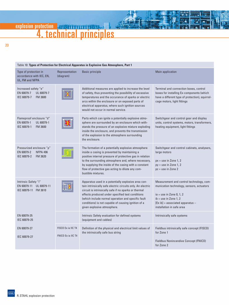
Table 10: Types of Protection for Electrical Apparatus in Explosive Gas Atmosphere, Part 1
Basic principle
Additional measures are applied to increase the levelof safety, thus preventing the possibility of excessivetemperatures and the occurance of sparks or electricarcs within the enclosure or on exposed parts ofelectrical apparatus, where such ignition sourceswould not occur in normal service.
Parts which can ignite a potentially explosive atmo-sphere are surrounded by an enclosure which with-stands the pressure of an explosive mixture explodinginside the enclosure, and prevents the transmission of the explosion to the atmosphere surrounding the enclosure.
The formation of a potentially explosive atmosphereinside a casing is prevented by maintaining a positive internal pressure of protective gas in relationto the surrounding atmosphere and, where necessary,by supplying the inside of the casing with a constantflow of protective gas acting to dilute any com-bustible mixtures.
Apparatus used in a potentially explosive area con-tain intrinsically safe electric circuits only. An electriccircuit is intrinsically safe if no sparks or thermaleffects produced under specified test conditions(which include normal operation and specific faultconditions) is not capable of causing ignition of a given explosive atmosphere.
Intrinsic Safety evaluation for defined systems(equipment and cables)
Definition of the physical and electrical limit values ofthe intrinsically safe bus string
Main application
Terminal and connection boxes, control boxes for installing Ex-components (which have a different type of protection), squirrel-cage motors, light fittings
Switchgear and control gear and display units, control systems, motors, transformers,heating equipment, light fittings
Switchgear and control cabinets, analysers,large motors
px = use in Zone 1, 2py = use in Zone 1, 2pz = use in Zone 2
Measurement and control technology, com-munication technology, sensors, actuators
ia = use in Zone 0, 1, 2ib = use in Zone 1, 2[Ex ib] = associated apparatus – installation in safe area
Intrinsically safe systems
Fieldbus intrinsically safe concept (FISCO)for Zone 1
Fieldbus Nonincendive Concept (FNICO) for Zone 2
Type of protection in accordance with IEC, EN, UL, FM and NFPA
Increased safety “e”EN 60079-7 UL 60079-7IEC 60079-7 FM 3600
Flameproof enclosure “d” EN 60079-1 UL 60079-1IEC 60079-1 FM 3600
Pressurized enclosure “p” EN 60079-2 NFPA 496IEC 60079-2 FM 3620
Intrinsic Safety “i”EN 60079-11 UL 60079-11IEC 60079-11 FM 3610
EN 60079-25IEC 60079-25
EN 60079-27
IEC 60079-27
Representation(diagram)
FISCO Ex ia IIC T4
FNICO Ex ia IIC T4
explosion protection
R. STAHL explosion protection
21
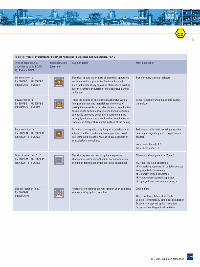
Table 11: Types of Protection for Electrical Apparatus in Explosive Gas Atmosphere, Part 2
Basic principle
Electrical apparatus or parts of electrical apparatusare immersed in a protective fluid (such as oil), such that a potentially explosive atmosphere existingover the surface or outside of the apparatus cannotbe ignited.
Filling the casing of an electrical apparatus with a fine granular packing material has the effect ofmaking it impossible for an electric arc created in thecasing under certain operating conditions to ignite apotentially explosive atmosphere surrounding thecasing. Ignition must not result either from flames orfrom raised temperature on the surface of the casing.
Parts that are capable of igniting an explosive atmo-sphere by either sparking or heating are enclosed in a compound in such a way as to avoid ignition of an explosive atmosphere.
Electrical apparatus cannot ignite a explosive atmosphere surrounding them (in normal operationand under defined abnormal operating conditions).
Appropriate measures prevent ignition of an explosiveatmosphere by optical radiation.
Main application
Transformers, starting resistors
Sensors, display units, electronic ballast, transmitter
Switchgear with small breaking capacity, control and signalling units, display units, sensors
ma = use in Zone 0, 1, 2mb = use in Zone 1, 2
All electrical equipment for Zone 2
nA = non-sparking apparatusnC = sparking apparatus in which contacts are protected convenientlynL = energy-limited apparatus nR = purged/pressurized apparatusnZ = purged pressurized apparatus, n
Optical fibre
There are three different methods:Ex op is = intrinsically safe optical radiationEx op pr = protected optical radiationEx op sh = blocking optical radiation
Type of protection in accordance with IEC, EN, UL, FM und NFPA
Oil immersion “o”EN 60079-6 UL 60079-6IEC 60079-6 FM 3600
Powder filling “q”EN 60079-5 UL 60079-5IEC 60079-5 FM 3600
Encapsulation “m”EN 60079-18 UL 60079-18IEC 60079-18 FM 3600
Type of protection “n_”EN 60079-15 UL 60079-15IEC 60079-15 FM 3600
Optical radiation “op_”EN 60079-28 IEC 60079-28
Representation(diagram)
R. STAHL explosion protection
4. technical principles22
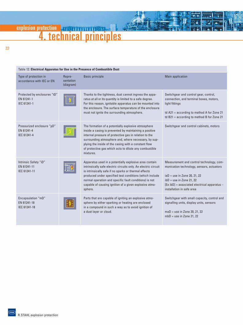
Table 12: Electrical Apparatus for Use in the Presence of Combustible Dust
Basic principle
Thanks to the tightness, dust cannot ingress the appa-ratus at all or its quantity is limited to a safe degree. For this reason, ignitable apparatus can be mounted intothe enclosure. The surface temperature of the enclosuremust not ignite the surrounding atmosphere.
The formation of a potentially explosive atmosphere inside a casing is prevented by maintaining a positive internal pressure of protective gas in relation to thesurrounding atmosphere and, where necessary, by sup-plying the inside of the casing with a constant flow of protective gas which acts to dilute any combustible mixtures.
Apparatus used in a potentially explosive area containintrinsically safe electric circuits only. An electric circuitis intrinsically safe if no sparks or thermal effects produced under specified test conditions (which include normal operation and specific fault conditions) is notcapable of causing ignition of a given explosive atmo-sphere.
Parts that are capable of igniting an explosive atmo-sphere by either sparking or heating are enclosed in a compound in such a way as to avoid ignition of a dust layer or cloud.
Main application
Switchgear and control gear, control, connection, and terminal boxes, motors, light fittings
td A21 = according to method A for Zone 21td B21 = according to method B for Zone 21
Switchgear and control cabinets, motors
Measurement and control technology, com-munication technology, sensors, actuators
iaD = use in Zone 20, 21, 22ibD = use in Zone 21, 22[Ex ibD] = associated electrical apparatus –installation in safe area
Switchgear with small capacity, control and signalling units, display units, sensors
maD = use in Zone 20, 21, 22mbD = use in Zone 21, 22
Type of protection in accordance with IEC or EN
Protected by enclosures “tD”EN 61241-1 IEC 61241-1
Pressurized enclosure “pD”EN 61241-4IEC 61241-4
Intrinsic Safety “iD” EN 61241-11IEC 61241-11
Encapsulation “mD” EN 61241-18IEC 61241-18
Repre-sentation(diagram)
explosion protection
R. STAHL explosion protection
23
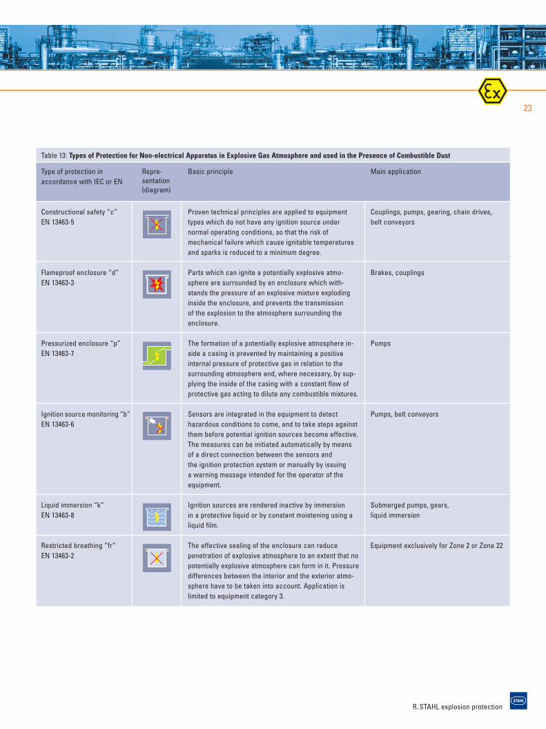
Table 13: Types of Protection for Non-electrical Apparatus in Explosive Gas Atmosphere and used in the Presence of Combustible Dust
Basic principle
Proven technical principles are applied to equipmenttypes which do not have any ignition source under normal operating conditions, so that the risk of mechanical failure which cause ignitable temperaturesand sparks is reduced to a minimum degree.
Parts which can ignite a potentially explosive atmo-sphere are surrounded by an enclosure which with-stands the pressure of an explosive mixture explodinginside the enclosure, and prevents the transmission of the explosion to the atmosphere surrounding theenclosure.
The formation of a potentially explosive atmosphere in-side a casing is prevented by maintaining a positiveinternal pressure of protective gas in relation to thesurrounding atmosphere and, where necessary, by sup-plying the inside of the casing with a constant flow ofprotective gas acting to dilute any combustible mixtures.
Sensors are integrated in the equipment to detect hazardous conditions to come, and to take steps againstthem before potential ignition sources become effective.The measures can be initiated automatically by meansof a direct connection between the sensors and the ignition protection system or manually by issuing a warning message intended for the operator of the equipment.
Ignition sources are rendered inactive by immersion in a protective liquid or by constant moistening using aliquid film.
The effective sealing of the enclosure can reduce penetration of explosive atmosphere to an extent that nopotentially explosive atmosphere can form in it. Pressuredifferences between the interior and the exterior atmo-sphere have to be taken into account. Application islimited to equipment category 3.
Main application
Couplings, pumps, gearing, chain drives, belt conveyors
Brakes, couplings
Pumps
Pumps, belt conveyors
Submerged pumps, gears, liquid immersion
Equipment exclusively for Zone 2 or Zone 22
Type of protection in accordance with IEC or EN
Constructional safety “c” EN 13463-5
Flameproof enclosure “d” EN 13463-3
Pressurized enclosure “p” EN 13463-7
Ignition source monitoring “b”EN 13463-6
Liquid immersion “k” EN 13463-8
Restricted breathing “fr” EN 13463-2
Repre-sentation(diagram)
R. STAHL explosion protection
4. technical principles24
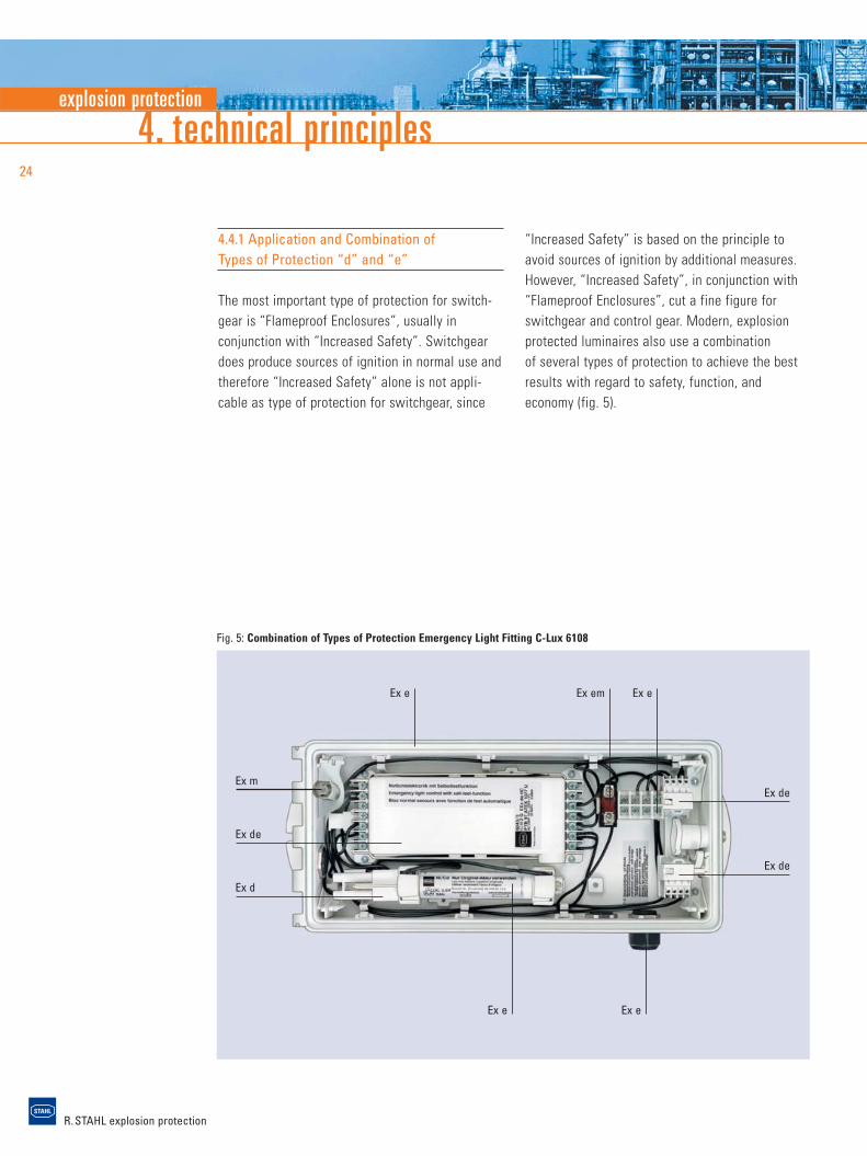
Fig. 5: Combination of Types of Protection Emergency Light Fitting C-Lux 6108
4.4.1 Application and Combination ofTypes of Protection “d” and “e”
The most important type of protection for switch-gear is “Flameproof Enclosures”, usually in conjunction with “Increased Safety”. Switchgeardoes produce sources of ignition in normal use andtherefore “Increased Safety” alone is not appli-cable as type of protection for switchgear, since
Ex de
Ex mEx de
Ex de
Ex d
Ex e Ex e
Ex e
“Increased Safety” is based on the principle toavoid sources of ignition by additional measures.However, “Increased Safety”, in conjunction with“Flameproof Enclosures”, cut a fine figure forswitchgear and control gear. Modern, explosionprotected luminaires also use a combination of several types of protection to achieve the bestresults with regard to safety, function, and economy (fig. 5).
Ex emEx e
explosion protection
R. STAHL explosion protection
25
4.4.2 Applications of Type of Protection“Intrinsic Safety”
The type of protection “Intrinsic Safety” is basedon the principle of energy limitation within anelectric circuit. The energy from a power circuitcapable of causing an explosive atmosphere toignite is thus limited to such an extent that thesurrounding explosive atmosphere cannot ignite as a result of sparks or inadmissible surface heat-ing of the electrical components.
The type of protection “Intrinsic Safety” is partic-ularly used in measurement and control tech-nology, as no high currents, voltage and power are required here.
Terms and Definitions
Intrinsically safe electrical circuitAn electric circuit in which neither a spark nor the effect of heat can cause a defined explosiveatmosphere to ignite.
Intrinsically safe apparatusElectrical apparatus in which all circuits are intrinsically safe.
Associated apparatusElectrical apparatus which contains circuits, someof which are intrinsically safe and some are not,and which is constructed such that the non-intrin-sically safe circuits cannot negatively adverselyaffect the intrinsically safe circuits (table 14).
Minimum ignition energyThe minimum ignition energy of a gas/air andvapour/air mixture is the smallest level of electri-cal energy which occurs while a capacitor is discharging, and which may still be sufficient toignite the most ignitable mixture of a gas orvapour and air at atmospheric pressure and 20 °C.
An essential aspect of the type of protection“Intrinsic Safety” is reliability with regard to theobservance of voltage and current limit values,even if determined faults may occur. Intrinsicallysafe apparatus and intrinsically safe componentsfrom related equipment are classified in differentlevels of protection “ia”, “ib” or “ic” with regardto infallibility. The level of protection “ia” is a prerequisite for category 1 equipment and suitablefor use in Zone 0, the level of protection “ib” for category 2 equipment and suitable for use inZone 1. The new level of protection “ic” for cate-gory 3 is suitable for use in Zone 2.
Table 14: Difference between Intrinsically Safe and Associated Apparatus
Intrinsically safe apparatus Associated apparatus
These contain intrinsically safe circuits only These contain both intrinsically safe and non-intrinsically safe electric circuits
EEx ib IIC T6 [EEx ib] IIC T6 EEx de [ib] IIC T6
All necessary information such as category, ex- The square brackets indicate that the associated electrical apparatus contains an intrinsicallyplosion group and temperature class is provided. safe electric circuit that may be introduced into Zone 1, gas groups IIA, IIB and IIC.
The apparatus may be used in Zone 1. The apparatus has to be installed outside Thanks to being integrated in a flameproof of the potentially explosive area. enclosure (“d”), the apparatus may be used
in Zone 1.
R. STAHL explosion protection
Level of protection “ia”
Electrical apparatus of level of protection ”ia”shall not be capable of causing ignition in normal operation and when one fault occurs orwhen a combination of any two faults occurs.
Safety factor 1.5:During normal operation and in case of onefault
Safety factor 1.0:Two independent faults
Level of protection “ib”
Electrical apparatus of level of protection ”ib”shall not be capable of causing ignition in normal operation or when one fault occurs.
Safety factor 1.5:During normal operation and in case of onefault
Safety factor 1.0:In case of one fault, if the electrical apparatusdoes not have unprotected switching contactsin those components, which may be exposed to an explosive atmosphere, and when the faultis monitored.
Table 15: Levels of protection of intrinsically safe electrical circuits
4. technical principles26
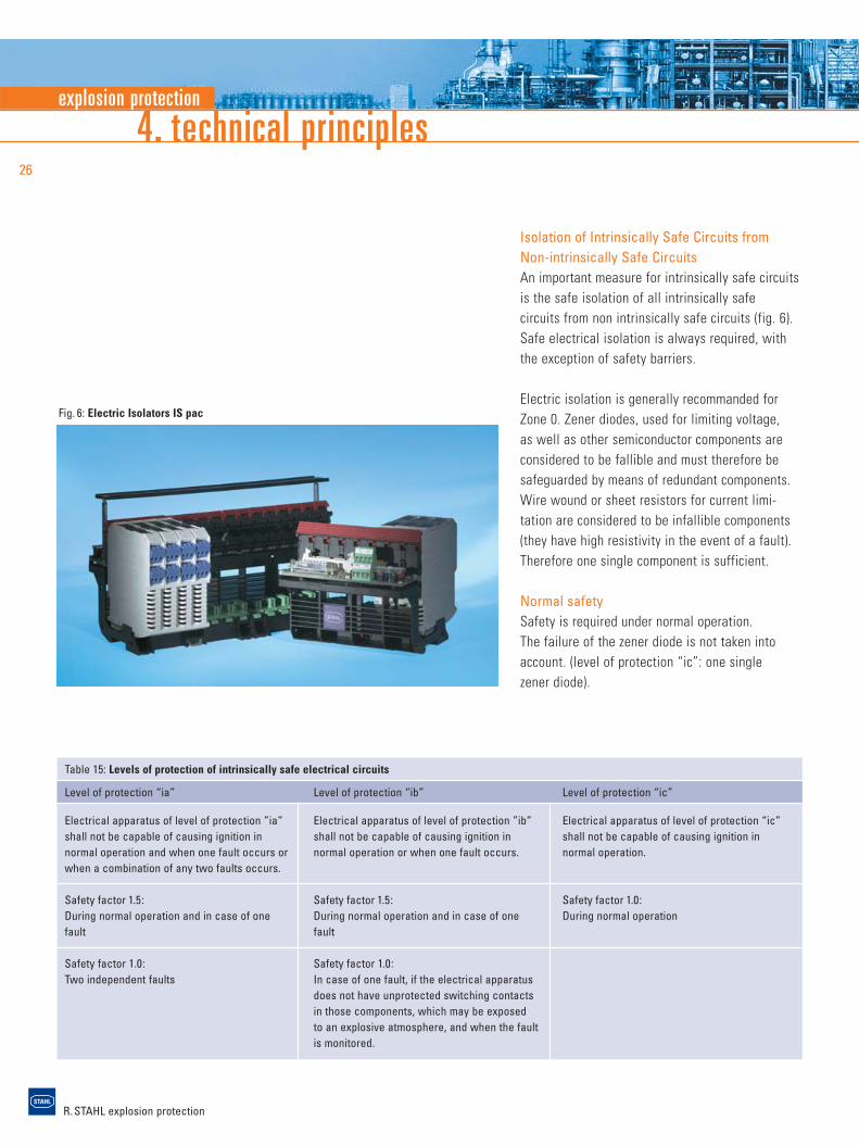
Fig. 6: Electric Isolators IS pac
Isolation of Intrinsically Safe Circuits fromNon-intrinsically Safe CircuitsAn important measure for intrinsically safe circuitsis the safe isolation of all intrinsically safe circuits from non intrinsically safe circuits (fig. 6). Safe electrical isolation is always required, with the exception of safety barriers.
Electric isolation is generally recommanded forZone 0. Zener diodes, used for limiting voltage, as well as other semiconductor components are considered to be fallible and must therefore besafeguarded by means of redundant components.Wire wound or sheet resistors for current limi-tation are considered to be infallible components(they have high resistivity in the event of a fault).Therefore one single component is sufficient.
Normal safetySafety is required under normal operation. The failure of the zener diode is not taken intoaccount. (level of protection “ic”: one single zener diode).
Level of protection “ic”
Electrical apparatus of level of protection “ic”shall not be capable of causing ignition in normal operation.
Safety factor 1.0:During normal operation
explosion protection
R. STAHL explosion protection
27
Single fault safetyIn the event of the failure of one zener diode, a second zener diode must take its function (level of protection “ib”: one redundant zenerdiode).
Double fault safetyIn the event of a failure of two zener diodes, a third zener diode must take their function(level of protection “ia”: two redundant zenerdiodes, table 15).
4.4.3 Applications of Type of Protection “c”
Non-electrical apparatus are often realised with thetype of protection “Constructional safety”. The riskof failure, which may cause ignition sources in an apparatus, is reduced to a low level by meansof constructional measures for this type of protec-tion. To do so, e.g., hot surfaces, mechanicallygenerated sparks, and electrostatic discharges areexamined. The measures depend mainly on theequipment type and may vary significantly. Here,the examined material combination, dimensioning, tolerances, and lubricants of moving parts play a role. Even servicing intervals and monitoring of the service life may be of vital importance. The manufacturer defines the intended use in the operating instructions. By doing so, ambient andoperating conditions as well as the admitted operating parameters are specified. The operatorhas to observe the operating instructions.
R. STAHL explosion protection
5. Installation and Operation of ElectricalEquipment in Hazardous Areas
5.1 Duties of Installer, Manufacturer and Employer
Safety in potentially explosive areas can only beguaranteed by a close and effective working relationship amongst all parties involved (fig. 7).The employer is responsible for the safety of hisinstallations. It is his duty to verify where there is a risk of explosion and then divide areas intoZones accordingly. He must ensure that the instal-lation is installed in accordance with regulationsand is inspected before initial use. The installationmust be kept in a regular and correct state by periodic inspection and maintenance.
The installer must observe the installation requirements, and select and install the electricapparatus correctly for its intended use.
Manufacturers of explosion protected apparatusare responsible for routine testing, certificationand documentation and are required to ensure thateach device manufactured complies with theapproved design.
5.2 Classification of Zones and Selection of Apparatus
The question of possible risks of explosion mustbe addressed at the early stages new facility planning. When classifying potentially explosiveareas, the influence of natural or technical ventilation must be considered in addition to thequantity of flammable substances being released.Furthermore, the explosion safety characteristicsmust be ascertained for the flammable
5. installation and operation of electrical equipment28
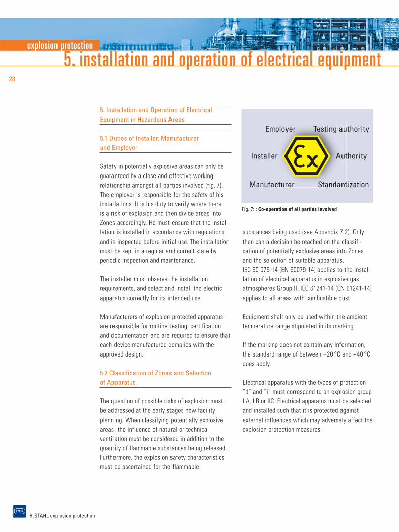
Installer
Employer Testing authority
Authority
Standardization Manufacturer
Fig. 7: : Co-operation of all parties involved
substances being used (see Appendix 7.2). Only then can a decision be reached on the classifi-cation of potentially explosive areas into Zonesand the selection of suitable apparatus. IEC 60 079-14 (EN 60079-14) applies to the instal-lation of electrical apparatus in explosive gasatmospheres Group II. IEC 61241-14 (EN 61241-14)applies to all areas with combustible dust.
Equipment shall only be used within the ambienttemperature range stipulated in its marking.
If the marking does not contain any information,the standard range of between –20 °C and +40 °Cdoes apply.
Electrical apparatus with the types of protection“d” and “i” must correspond to an explosion groupIIA, IIB or IIC. Electrical apparatus must be selectedand installed such that it is protected againstexternal influences which may adversely affect the explosion protection measures.
explosion protection
R. STAHL explosion protection
29
5.3 Methods of Installation
Essentially, three systems are used for electricalinstallations in hazardous areas:> 1. Cable system with indirect entry> 2. Cable system with direct entry> 3. Conduit system The technical design of the electrical apparatusused with the individual types of installation is accordingly different.
Only the conduit system or mineral insulatedcables (MI) are permitted in the USA for all appli-cations in Class 1, Division 1 in accordance withNEC 501-4, whereby the mineral insulated cablesare mainly used as heating lines and fire resistantsignal and control lines. Certain types of cable and line are also permitted in Division 2. A com-parison of the various systems is shown below.
Cable systemsCable systems are mainly used in Europe. For this,high-quality cables are laid uncovered. It is only in areas in which mechanical damage could be expected that they are laid in conduits that areopen at both ends.
In the case of indirect entry, the cables and linesare conducted via cable glands into a connectionchamber in the type of protection “IncreasedSafety” and connected to the terminals also pro-vided in “Increased Safety”. From here, the individual wires are conducted via flameproofbushings into the flameproof enclosure.
The cable bushings are installed by the manufac-turer, with the result that, by contrast with direct entry, a routine test of the factory wiredflameproof enclosure can be made.
The installation engineer need only open the connection chamber for the connection, not theflameproof enclosure.
In the case of direct entry, the connecting cables are entered directly into the flameproof enclosure. Only cable glands that have been specially certified for this purpose may be used for this type of entry.
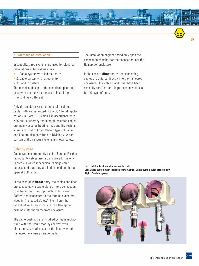
Fig. 8: Methods of Installation worldwide:Left: Cable system with indirect entry; Centre: Cable system with direct entry;Right: Conduit system
R. STAHL explosion protection
5. installation and operation of electrical equipment30
The flexible gasket and the cable sheath mustform a flameproof joint through which no flamescan penetrate. For this reason, attention must be paid to the appropriate selection of cable glanddepending on both the type and structure of cable and installation location. If the flameproofenclosure has to be used in a IIC atmosphere or if a flameproof enclosure with a volume biggerthan 2 dm3 has to be applied in Zone 1, the gas-kets or cable glands have to be sealed. The flame-proof enclosure primarily depends here on the care taken by the electrician when connecting thecables.
Conduit SystemIn the case of installation using the conduit sys-tem, the electrical lines are drawn as single wiresinto enclosed metal conduits. The conduits are connected to the housings by means of fittingsand equipped with a seal at each entrance point. The entire conduit system is flameproof. The aimof the seal is to prevent explosions which mayoccur inside the housing from transmitting intothe conduit. Otherwise, extremely high explosionpressures would be created as a result of pre-compression in long cylindrical tubes. For this reason, it is recommended that seals be installed not just at the entrance points but at specificintervals. Drains must be installed at low points at which condensate can accumulate.
5.4 Maintenance
Periodic maintenance is required to maintain thesafety of electrical installations in hazardousareas. Personnel who carry out such maintenancework should work under the guidance of an explosion protection expert and should be in-formed of the particular hazards involved (skilledperson, IEC 60079-17).
Before corrective maintenance, it must be ensuredthat there is no danger of explosions occurringduring this work. Normally, formal written work-permission for this should be acquired from thecompany management. On completion of the work,a documentation should be kept of what work was carried out, and confirmation given that allrelevant regulations have been observed.
A technical person with executive function shallbe identified for each installation. He is respon-sible for the determination of the frequency of inspection, the grade of inspection, the avail-ability of the documentation, the training for theskilled personel, etc.
explosion protection
R. STAHL explosion protection
6. explosion protection in north america31
6. Explosion Protection in North America
6.1 Introduction
The basic principles of explosion protection are the same all over the world. However, tech-nologies have developed in North America in thefield of explosion protection for electrical equip-ment and installations which deviate considerablyfrom those of the IEC (International Electrotech-nical Commission). The differences from IEC tech-nologies are among others the classification ofhazardous locations, the construction of apparatusand the installation of electrical systems.
6.2 Classification of Hazardous Locations
For potentially explosive atmospheres the term“hazardous (classified) locations” is used in North America. These are defined in Articles 500and 505 of the National Electrical Code (NEC) in the USA and in Section 18 and Annex J of theCanadian Electrical Code (CEC) in Canada. Hazardous locations are locations, where fire orexplosion hazards may exist due to flammablegases, vapours or mists (Class I), combustibledusts (Class II), or ignitable fibres or flyings (Class III).
Based on the likelihood or risk that an ignitableconcentration of a flammable substance will bepresent the hazardous locations are traditionallysubdivided into Division 1 and Division 2.
In 1996 the IEC classification system was intro-duced as a parallel system to the existing systemfor Class I in the USA. This system was imple-mented by the new Article 505. This now gives the end user the possibility to choose the systemthat best suits his needs.
The IEC zone classification for Class I was alsointroduced in Canada (CEC, 1988 edition). All newly built facilities in Canada need to beclassified according to this principle.
The traditional North American classification system divides Class I flammable gases, vapours,mists and liquids into Gas Groups A, B, C and D,and Class II combustible dusts into Groups E, Fand G.
Group A is the most hazardous gas group in thetraditional NEC system whereas Group IIC is the most hazardous group in the IEC system inArticle 505 of the NEC.
In Canada both gas grouping systems may be usedwith the zone classification system.
The maximum surface temperature determinationgiven in the new Article 505 maintains a pure IEC approach of having main temperature classesT1 to T6 with further subdivisions of the tempera-ture classes in the Division system. In the 1998CEC, this structure T1–T6 with intermediate sub-divisions was maintained.
Table 19 in appendix 7.3 provides an overview of the classification of hazardous locations in North America.
R. STAHL explosion protection
6. explosion protection in north america32
6.3 Regulations for Installation
The National Electrical Code in the USA and theCanadian Electrical Code in Canada apply to electrical apparatus and installations for hazardouslocations. These have the nature of installationregulations for electrical facilities in all locations,and refer to a number of further standards of otherinstitutions that contain specifications for theerection and construction of suitable equipment.
The methods of installation for the zone concept in accordance with the NEC are similar to the traditional Class/Division system. New to the NEC1996 is the use of listed Metal Clad (MC) cablesin addition to rigid conduit and Mineral Insulatedcables in Class I, Division 1 or Zone 1.
One significant advantage to the CEC is theincreased possibility of using cables. In contrast to the USA, Canada has, for some time now, also permitted the use of special cables similar tothe IEC steel-wire armoured cables.
6.4 Construction and Design Requirements
The regulations of the National Electrical Codeand the Canadian Electrical Code stipulate whichapparatus and types of protection may be used in different hazardous locations.
Various standards and regulations govern the construction and testing of explosion-protectedelectrical apparatus and installations in North America. In the USA, these are mainly thestandards issued by Underwriters Laboratories Inc.(UL), Factory Mutual Research Corporation (FM)and the International Society for Measurementand Control (ISA). In Canada, those of theCanadian Standards Association (CSA) apply.
The tables in appendix 7.4 provide an overview of the constructional requirements for hazardouslocations and methods of protection.
6.5 Degrees of Protection provided byEnclosures
As the standard IEC 60 529 defines the degrees of protection provided by enclosures, as in theUSA the degrees of protection are included in theNEMA Publication No. 250 (National ElectricalManufacturing Association). These enclosure typescannot be exactly equated with the IEC enclosureclassification designation since NEMA takes additional environmental influences (such as cool-ing lubricant, cutting coolant, corrosion, icing, hail)into account. The tables 7.5 and 7.6 in the ap-pendix illustrate the types of protection accordingto both standards.
explosion protection
R. STAHL explosion protection
33
6.6 Certification and Marking
In the USA and Canada, electrical apparatus andapparatus used in hazardous locations are, as a rule, subject to approval. Exceptions to this areitems of electrical apparatus which, due to theirdesign and the peculiar nature of the explosiveatmosphere in which they are used, cannot ignite. The responsible authorities shall decide whethersuch equipment is subject to approval.
Equipment which has been developed and manufactured for use in hazardous locations istested and approved in the USA and Canada by anotified testing authority. In the USA, this is forexample the Underwriters Laboratories or FactoryMutual, and in Canada the Canadian StandardsAssociation.
In addition to data such as manufacturer, type,serial number, and electrical data, any data relat-ing to explosion protection must be shown on the marking of the equipment. The requirementsfor this are specified in the NEC, the CEC as well as the relevant apparatus regulations of the testing authority.
Class I, II & III, Division 1 and 2The approved electrical equipment for Class I,Class II and Class III, Division 1 and Division 2must be marked to show the following information:1. Class(es), Division(s)
(optional except for Division 2)2. Gas/dust group(s)3. Operating temperature or temperature class
(optional T5 and T6)Example: Class I Division 1 Groups C D T4
Class I, Zone 0, 1 and 2For equipment intended for use in Class I, Zone 0,Zone 1 or Zone 2, a distinction is made between“Division Equipment” and “Zone Equipment”.
(1) Division EquipmentEquipment approved for Class I, Division 1 and/orClass I, Division 2 shall be permitted to be markedwith the following:1. Class I, Zone 1 or Class I, Zone 22. Gas group(s) IIA, IIB or IIC3. Temperature class4. Types of ProtectionExample: Class I Zone 1 d,e IIC T4
(2) Zone EquipmentEquipment meeting one or more types of protection described in Article 505 of the NEC or Section 18 of the CEC shall be marked with the following in the order shown:1. Class (optional in Canada)2. Zone (optional in Canada)3. AEx (USA) or Ex or EEx (Canada)4. Type(s) of protection5. Equipment group II or applicable gas group(s)
IIA, IIB or IIC6. Temperature classExample: Class I Zone 0 AEx ia IIC T6
R. STAHL explosion protection
7. appendix34
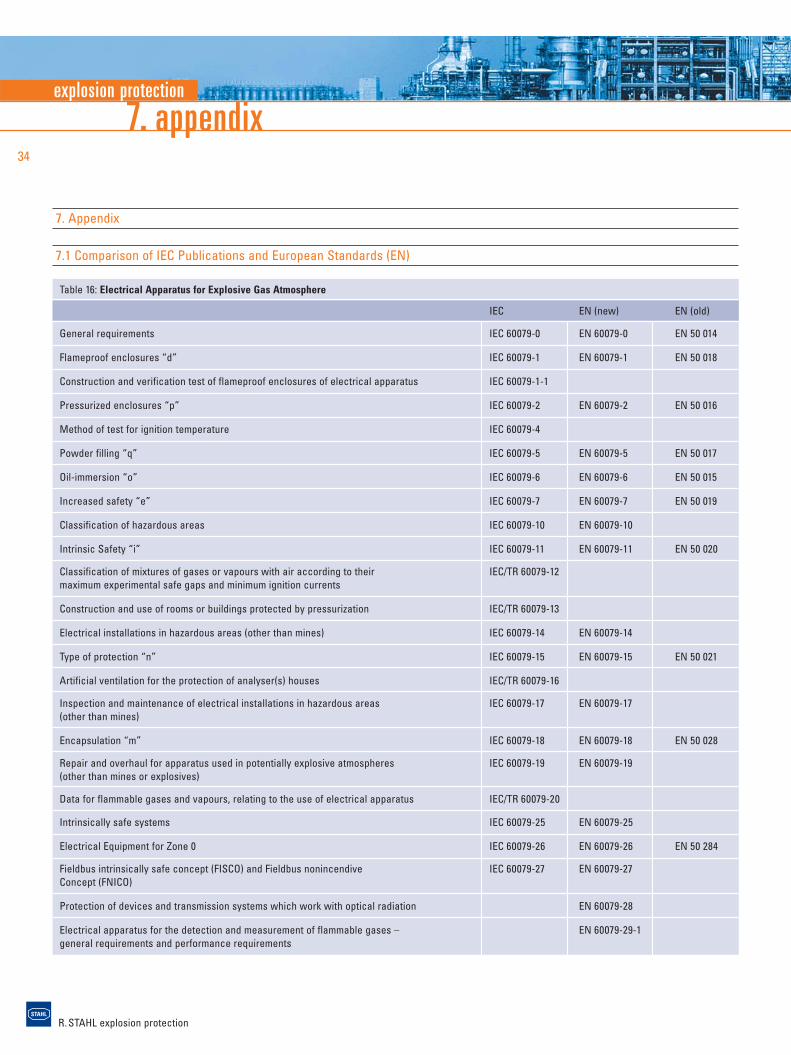
Table 16: Electrical Apparatus for Explosive Gas Atmosphere
IEC EN (new) EN (old)
General requirements IEC 60079-0 EN 60079-0 EN 50 014
Flameproof enclosures “d” IEC 60079-1 EN 60079-1 EN 50 018
Construction and verification test of flameproof enclosures of electrical apparatus IEC 60079-1-1
Pressurized enclosures “p” IEC 60079-2 EN 60079-2 EN 50 016
Method of test for ignition temperature IEC 60079-4
Powder filling “q” IEC 60079-5 EN 60079-5 EN 50 017
Oil-immersion “o” IEC 60079-6 EN 60079-6 EN 50 015
Increased safety “e” IEC 60079-7 EN 60079-7 EN 50 019
Classification of hazardous areas IEC 60079-10 EN 60079-10
Intrinsic Safety “i” IEC 60079-11 EN 60079-11 EN 50 020
Classification of mixtures of gases or vapours with air according to their IEC/TR 60079-12maximum experimental safe gaps and minimum ignition currents
Construction and use of rooms or buildings protected by pressurization IEC/TR 60079-13
Electrical installations in hazardous areas (other than mines) IEC 60079-14 EN 60079-14
Type of protection “n” IEC 60079-15 EN 60079-15 EN 50 021
Artificial ventilation for the protection of analyser(s) houses IEC/TR 60079-16
Inspection and maintenance of electrical installations in hazardous areas IEC 60079-17 EN 60079-17(other than mines)
Encapsulation “m” IEC 60079-18 EN 60079-18 EN 50 028
Repair and overhaul for apparatus used in potentially explosive atmospheres IEC 60079-19 EN 60079-19(other than mines or explosives)
Data for flammable gases and vapours, relating to the use of electrical apparatus IEC/TR 60079-20
Intrinsically safe systems IEC 60079-25 EN 60079-25
Electrical Equipment for Zone 0 IEC 60079-26 EN 60079-26 EN 50 284
Fieldbus intrinsically safe concept (FISCO) and Fieldbus nonincendive IEC 60079-27 EN 60079-27Concept (FNICO)
Protection of devices and transmission systems which work with optical radiation EN 60079-28
Electrical apparatus for the detection and measurement of flammable gases – EN 60079-29-1general requirements and performance requirements
7. Appendix
7.1 Comparison of IEC Publications and European Standards (EN)
explosion protection
R. STAHL explosion protection
35
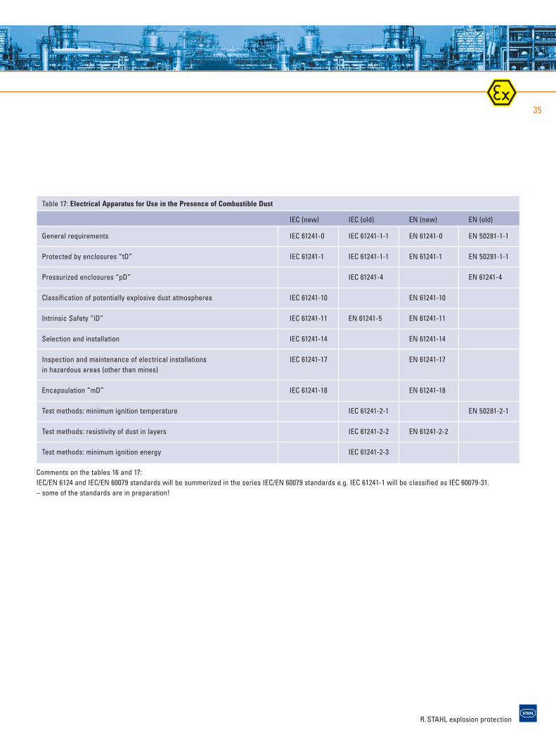
Table 17: Electrical Apparatus for Use in the Presence of Combustible Dust
IEC (new) IEC (old) EN (new) EN (old)
General requirements IEC 61241-0 IEC 61241-1-1 EN 61241-0 EN 50281-1-1
Protected by enclosures “tD” IEC 61241-1 IEC 61241-1-1 EN 61241-1 EN 50281-1-1
Pressurized enclosures “pD” IEC 61241-4 EN 61241-4
Classification of potentially explosive dust atmospheres IEC 61241-10 EN 61241-10
Intrinsic Safety “iD” IEC 61241-11 EN 61241-5 EN 61241-11
Selection and installation IEC 61241-14 EN 61241-14
Inspection and maintenance of electrical installations IEC 61241-17 EN 61241-17in hazardous areas (other than mines)
Encapsulation “mD” IEC 61241-18 EN 61241-18
Test methods: minimum ignition temperature IEC 61241-2-1 EN 50281-2-1
Test methods: resistivity of dust in layers IEC 61241-2-2 EN 61241-2-2
Test methods: minimum ignition energy IEC 61241-2-3
Comments on the tables 16 and 17: IEC/EN 6124 and IEC/EN 60079 standards will be summerized in the series IEC/EN 60079 standards e.g. IEC 61241-1 will be classified as IEC 60079-31. – some of the standards are in preparation!
R. STAHL explosion protection
7. appendix36
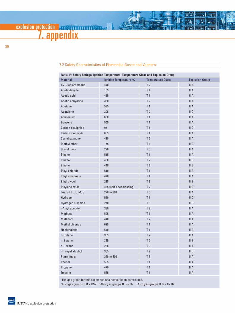
7.2 Safety Characteristics of Flammable Gases and Vapours
Table 18: Safety Ratings: Ignition Temperature, Temperature Class and Explosion Group
Material Ignition Temperature °C Temperature Class Explosion Group
1,2-Dichloroethane 440 T 2 II A
Acetaldehyde 155 T 4 II A
Acetic acid 485 T 1 II A
Acetic anhydride 330 T 2 II A
Acetone 535 T 1 II A
Acetylene 305 T 2 II C 3
Ammonium 630 T 1 II A
Benzene 555 T 1 II A
Carbon disulphide 95 T 6 II C 1
Carbon monoxide 605 T 1 II A
Cyclohexanone 430 T 2 II A
Diethyl ether 175 T 4 II B
Diesel fuels 220 T 3 II A
Ethane 515 T 1 II A
Ethanol 400 T 2 II B
Ethene 440 T 2 II B
Ethyl chloride 510 T 1 II A
Ethyl ethanoate 470 T 1 II A
Ethyl glycol 235 T 3 II B
Ethylene oxide 435 (self-decomposing) T 2 II B
Fuel oil EL, L, M, S 220 to 300 T 3 II A
Hydrogen 560 T 1 II C 2
Hydrogen sulphide 270 T 3 II B
i-Amyl acetate 380 T 2 II A
Methane 595 T 1 II A
Methanol 440 T 2 II A
Methyl chloride 625 T 1 II A
Naphthalene 540 T 1 II A
n-Butane 365 T 2 II A
n-Butanol 325 T 2 II B
n-Hexane 230 T 3 II A
n-Propyl alcohol 385 T 2 II B*
Petrol fuels 220 to 300 T 3 II A
Phenol 595 T 1 II A
Propane 470 T 1 II A
Toluene 535 T 1 II A
*The gas group for this substance has not yet been determined.1Also gas groups II B + CS2 2Also gas groups II B + H2 3Also gas groups II B + C2 H2
explosion protection
R. STAHL explosion protection
37
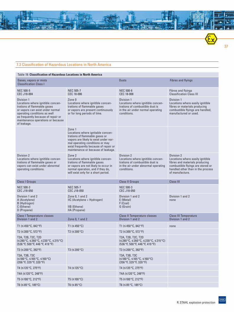
7.3 Classification of Hazardous Locations in North America
Table 19: Classification of Hazardous Locations in North America
Gases, vapors or mists Dusts Fibres and flyingsClassification Class I
NEC 500-5 CEC J18-004
Division 1 Locations where ignitible concen-trations of flammable gases or vapors can exist under normaloperating conditions as well as frequently because of repair ormaintenance operations or becauseof leakage.
Division 2 Locations where ignitible concen-trations of flammable gases orvapors can exist under abnormaloperating conditions.
Class I Groups
NEC 500-3 CEC J18-050
Division 1 and 2 A (Acetylene) B (Hydrogen) C (Ethene) D (Propane)
Class I Temperature classes Division 1 and 2
T1 (≤ 450 °C, 842 °F)
T2 (≤300 °C, 572 °F)
T2A, T2B, T2C, T2D (≤280 °C, ≤260 °C, ≤230 °C, ≤215 °C)(536 °F, 500 °F, 446 °F, 419 °F)
T3 (≤200 °C, 392°F)
T3A, T3B, T3C (≤180 °C, ≤165 °C, ≤160 °C)(356 °F, 329 °F, 320 °F)
T4 (≤135 °C, 275°F)
T4A (≤120 °C, 248°F)
T5 (≤100 °C, 212°F)
T6 (≤ 85 °C, 185°C)
NEC 505-7 CEC 18-006
Zone 0 Locations where ignitible concen-trations of flammable gases or vapors are present continuouslyor for long periods of time.
Zone 1 Locations where ignitable concen-trations of flammable gases orvapors are likely to exist under nor-mal operating conditions or mayexist frequently because of repair ormaintenance or because of leakage.
Zone 2 Locations where ignitible concen-trations of flammable gases or vapors are not likely to occur innormal operation, and if they do, will exist only for a short period.
NEC 505-7 CEC J18-050
Zone 0, 1 and 2 IIC (Acetylene + Hydrogen)
IIB (Ethene) IIA (Propane)
Zone 0, 1 and 2
T1 (≤ 450 °C)
T2 (≤300 °C)
T3 (≤200 °C)
T4 (≤135 °C)
T5 (≤100 °C)
T6 (≤ 85 °C)
NEC 500-6 CEC 18-008
Division 1Locations where ignitible concen- trations of combustible dust is in the air under normal operatingconditions.
Division 2 Locations where ignitible concen-trations of combustible dust is in the air under abnormal operatingconditions.
Class II Groups
NEC 500-3 CEC J18-050
Division 1 and 2 E (Metal)F (Coal)G (Grain)
Class II Temperature classes Division 1 and 2
T1 (≤ 450 °C, 842 °F)
T2 (≤300 °C, 572 °F)
T2A, T2B, T2C, T2D (≤280 °C, ≤260 °C, ≤230 °C, ≤215 °C)(536 °F, 500 °F, 446 °F, 419 °F)
T3 (≤200 °C, 392°F)
T3A, T3B, T3C (≤180 °C, ≤165 °C, ≤160 °C)(356 °F, 329 °F, 320 °F)
T4 (≤135 °C, 275°F)
T4A (≤120 °C, 248°F)
T5 (≤100 °C, 212°F)
T6 (≤ 85 °C, 185°C)
Fibres and flyings Classification Class III
Division 1Locations where easily ignitiblefibres or materials producing combustible flyings are handled,manufactured or used.
Division 2 Locations where easily ignitiblefibres and materials producing combustible flyings are stored or handled other than in the process of manufacture.
Class III
Division 1 and 2 none
Class III Temperature Division 1 and 2
none
R. STAHL explosion protection
7. appendix38
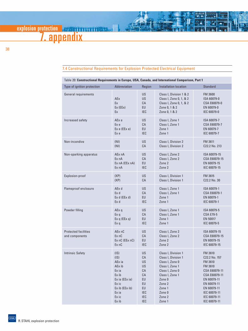
7.4 Constructional Requirements for Explosion Protected Electrical Equipment
Table 20: Constructional Requirements in Europe, USA, Canada, and International Comparison, Part 1
Type of ignition protection Abbreviation Region Installation location Standard
General requirements US Class I, Division 1 & 2 FM 3600AEx US Class I, Zone 0, 1, & 2 ISA 60079-0Ex CA Class I, Zone 0, 1, & 2 CSA E60079-0Ex (EEx) EU Zone 0, 1 & 2 EN 60079-0Ex IEC Zone 0, 1 & 2 IEC 60079-0
Increased safety AEx e US Class I, Zone 1 ISA 60079-7Ex e CA Class I, Zone 1 CSA E60079-7Ex e (EEx e) EU Zone 1 EN 60079-7Ex e IEC Zone 1 IEC 60079-7
Non-incendive (NI) US Class I, Division 2 FM 3611(NI) CA Class I, Division 2 C22.2 No. 213
Non-sparking apparatus AEx nA US Class I, Zone 2 ISA 60079-15Ex nA CA Class I, Zone 2 CSA E60079-15Ex nA (EEx nA) EU Zone 2 EN 60079-15Ex nA IEC Zone 2 IEC 60079-15
Explosion-proof (XP) US Class I, Division 1 FM 3615(XP) CA Class I, Division 1 C22.2 No. 30
Flameproof enclosure AEx d US Class I, Zone 1 ISA 60079-1Ex d CA Class I, Zone 1 CSA E60079-1Ex d (EEx d) EU Zone 1 EN 60079-1Ex d IEC Zone 1 IEC 60079-1
Powder filling AEx q US Class I, Zone 1 ISA 60079-5Ex q CA Class I, Zone 1 CSA E79-5Ex q (EEx q) EU Zone 1 EN 50017Ex q IEC Zone 1 IEC 60079-5
Protected facilities AEx nC US Class I, Zone 2 ISA 60079-15and components Ex nC CA Class I, Zone 2 CSA E60079-15
Ex nC (EEx nC) EU Zone 2 EN 60079-15Ex nC IEC Zone 2 IEC 60079-15
Intrinsic Safety (IS) US Class I, Division 1 FM 3610(IS) CA Class I, Division 1 C22.2 No. 157AEx ia US Class I, Zone 0 FM 3610AEx ib US Class I, Zone 1 FM 3610Ex ia CA Class I, Zone 0 CSA E60079-11Ex ib CA Class I, Zone 1 CSA E60079-11Ex ia (EEx ia) EU Zone 0 EN 60079-11Ex ic EU Zone 2 EN 60079-11Ex ib (EEx ib) EU Zone 1 EN 60079-11Ex ia IEC Zone 0 IEC 60079-11Ex ic IEC Zone 2 IEC 60079-11Ex ib IEC Zone 1 IEC 60079-11
explosion protection
R. STAHL explosion protection
39
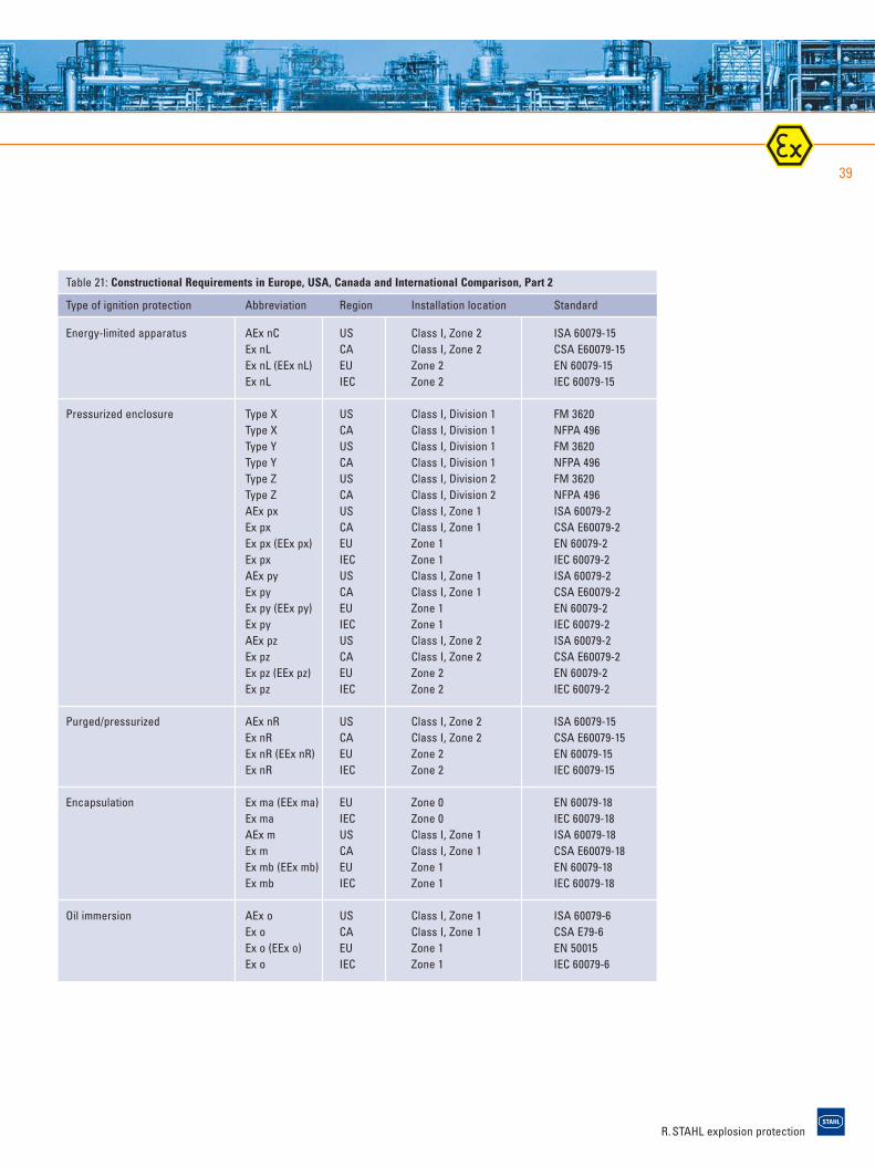
Table 21: Constructional Requirements in Europe, USA, Canada and International Comparison, Part 2
Type of ignition protection Abbreviation Region Installation location Standard
Energy-limited apparatus AEx nC US Class I, Zone 2 ISA 60079-15Ex nL CA Class I, Zone 2 CSA E60079-15Ex nL (EEx nL) EU Zone 2 EN 60079-15Ex nL IEC Zone 2 IEC 60079-15
Pressurized enclosure Type X US Class I, Division 1 FM 3620Type X CA Class I, Division 1 NFPA 496Type Y US Class I, Division 1 FM 3620Type Y CA Class I, Division 1 NFPA 496Type Z US Class I, Division 2 FM 3620Type Z CA Class I, Division 2 NFPA 496AEx px US Class I, Zone 1 ISA 60079-2Ex px CA Class I, Zone 1 CSA E60079-2Ex px (EEx px) EU Zone 1 EN 60079-2Ex px IEC Zone 1 IEC 60079-2AEx py US Class I, Zone 1 ISA 60079-2Ex py CA Class I, Zone 1 CSA E60079-2Ex py (EEx py) EU Zone 1 EN 60079-2Ex py IEC Zone 1 IEC 60079-2AEx pz US Class I, Zone 2 ISA 60079-2Ex pz CA Class I, Zone 2 CSA E60079-2Ex pz (EEx pz) EU Zone 2 EN 60079-2Ex pz IEC Zone 2 IEC 60079-2
Purged/pressurized AEx nR US Class I, Zone 2 ISA 60079-15Ex nR CA Class I, Zone 2 CSA E60079-15Ex nR (EEx nR) EU Zone 2 EN 60079-15Ex nR IEC Zone 2 IEC 60079-15
Encapsulation Ex ma (EEx ma) EU Zone 0 EN 60079-18Ex ma IEC Zone 0 IEC 60079-18AEx m US Class I, Zone 1 ISA 60079-18Ex m CA Class I, Zone 1 CSA E60079-18Ex mb (EEx mb) EU Zone 1 EN 60079-18Ex mb IEC Zone 1 IEC 60079-18
Oil immersion AEx o US Class I, Zone 1 ISA 60079-6Ex o CA Class I, Zone 1 CSA E79-6Ex o (EEx o) EU Zone 1 EN 50015Ex o IEC Zone 1 IEC 60079-6
R. STAHL explosion protection
7. appendix40
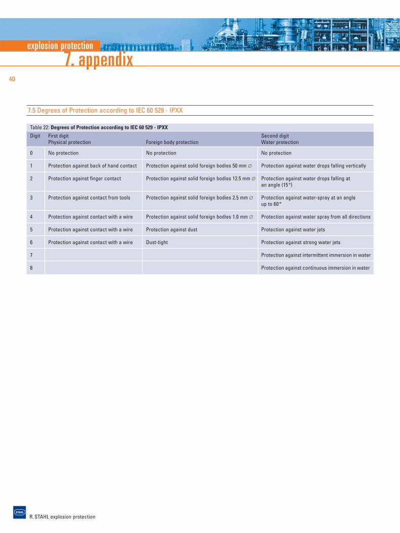
7.5 Degrees of Protection according to IEC 60 529 - IPXX
Table 22: Degrees of Protection according to IEC 60 529 - IPXX
Digit First digit Second digitPhysical protection Foreign body protection Water protection
0 No protection No protection No protection
1 Protection against back of hand contact Protection against solid foreign bodies 50 mm ∅ Protection against water drops falling vertically
2 Protection against finger contact Protection against solid foreign bodies 12.5 mm ∅ Protection against water drops falling at an angle (15 °)
3 Protection against contact from tools Protection against solid foreign bodies 2.5 mm ∅ Protection against water-spray at an angle up to 60 °
4 Protection against contact with a wire Protection against solid foreign bodies 1.0 mm ∅ Protection against water spray from all directions
5 Protection against contact with a wire Protection against dust Protection against water jets
6 Protection against contact with a wire Dust-tight Protection against strong water jets
7 Protection against intermittent immersion in water
8 Protection against continuous immersion in water
explosion protection
R. STAHL explosion protection
41
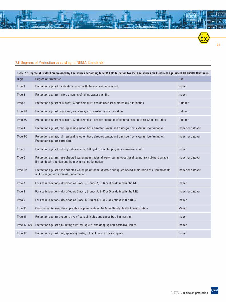
Table 23: Degree of Protection provided by Enclosures according to NEMA (Publication No. 250 Enclosures for Electrical Equipment 1000 Volts Maximum)
Digit Degree of Protection Use
Type 1 Protection against incidental contact with the enclosed equipment. Indoor
Type 2 Protection against limited amounts of falling water and dirt. Indoor
Type 3 Protection against rain, sleet, windblown dust, and damage from external ice formation Outdoor
Type 3R Protection against rain, sleet, and damage from external ice formation. Outdoor
Type 3S Protection against rain, sleet, windblown dust, and for operation of external mechanisms when ice laden. Outdoor
Type 4 Protection against, rain, splashing water, hose directed water, and damage from external ice formation. Indoor or outdoor
Type 4X Protection against, rain, splashing water, hose directed water, and damage from external ice formation. Indoor or outdoorProtection against corrosion.
Type 5 Protection against settling airborne dust, falling dirt, and dripping non-corrosive liquids. Indoor
Type 6 Protection against hose directed water, penetration of water during occasional temporary submersion at a Indoor or outdoorlimited depth, and damage from external ice formation.
Type 6P Protection against hose directed water, penetration of water during prolonged submersion at a limited depth, Indoor or outdoorand damage from external ice formation.
Type 7 For use in locations classified as Class I, Groups A, B, C or D as defined in the NEC. Indoor
Type 8 For use in locations classified as Class I, Groups A, B, C or D as defined in the NEC. Indoor or outdoor
Type 9 For use in locations classified as Class II, Groups E, F or G as defined in the NEC. Indoor
Type 10 Constructed to meet the applicable requirements of the Mine Safety Health Administration. Mining
Type 11 Protection against the corrosive effects of liquids and gases by oil immersion. Indoor
Type 12, 12K Protection against circulating dust, falling dirt, and dripping non-corrosive liquids. Indoor
Type 13 Protection against dust, splashing water, oil, and non-corrosive liquids. Indoor
7.6 Degrees of Protection according to NEMA Standards
R. STAHL explosion protection
8. literatureexplosion protection
42
8. Literature
Directive 94/9/EU of the European Parliament andthe council of 23 March 1994 on the approxima-tion of the laws of the member states concerningequipment and protective systems intended foruse in potentially explosive atmospheres.Official Journal of the European Communities, No. L 100/1
The Equipment and Protective Systems for Use in Potentially Explosive Atmospheres Regulations,1996 (EPS), ATEX 95 (UK). Explosionsschutzver-ordnung (ExVO) – Verordnung über das Inverkehr-bringen von Geräten und Schutzsystemen fürexplosionsgefährdete Bereiche. 11. GPSV(Explosion Protection Regulation). – Germany
Directive 99/92/EC on the “Minimum requirementsfor improving the health and safety protectionof the worker at risk from explosive atmospheres”16/12/1999, Official Journal of the EuropeanCommunities, L23/57–64
The Dangerous Substances and Explosive Atmo-spheres Regulations 2002, Statutory Instrument2002 No. 2776 (UK). Verordnung über Sicherheitund Gesundheitsschutz bei der Bereitstellung vonArbeitsmitteln und deren Benutzung bei der Arbeit,über Sicherheit beim Betrieb überwachungs-bedürftiger Anlagen und über die Organisation desbetrieblichen Arbeitsschutzes – Betriebssicher-heitsverordnung (BetrSichV) (Regulation on safetyand health protection in the provision of workequipment and its use, on safety when operatinginstallations requiring special state regulation andsupervision and on the organisation of safety atwork) – Germany
Regeln für das Vermeiden der Gefahren durchexplosionsfähige Atmosphäre – Explosionsschutz-regeln (ExRL) (Rules for the avoidance of hazardsfrom explosive atmospheres – Explosion ProtectionRules) published by the “Hauptverband dergewerblichen Berufsgenossenschaften”,Fachausschuss Chemie der BGZ, BGR 104
E. Brandes, W. MöllerSicherheitstechnische Kenngrößen Band 1: Brennbare Flüssigkeiten und Gase (Safety Characteristics Vol. 1: Flammable Liquids and Gases) Wissenschaftsverlag NW Verlag für neue Wissenschaft GmbH
Molnárné, Schendler, SchröderSicherheitstechnische Kenngrößen Band 2:Explosionsbereiche von Gasgemischen (Safety Characteristics: Vol. 2: Explosion regions of gas mixtures) Wissenschaftsverlag NW Verlag für neue Wissenschaft GmbH
M. Hattwig, H. SteenHandbook of Explosion Prevention and ProtectionWiley VCH, 2004, ISBN 3527307184
IEC 60079 or EN 60079 seriesElectrical apparatus for explosive gas atmospheres VDE-Verlag GmbH, Berlin
IEC 61241 and EN 61241 seriesElectrical apparatus for use in the presence ofcombustible dust
R. STAHL explosion protection
43
EN 60 529Specification for degrees of protection provided byenclosures (IP code)
EN 13463 Part 1 – Part 8Non-electrical equipment for potentially explosiveatmospheres
Dust explosion prevention and protection for machines and equipmentISSA Prevention Series No. 2033 (G)
Dust explosionsISSA Prevention Series No. 2044 (G)
The basics of dust explosion protectionR. STAHL Schaltgeräte GmbH
Operators of electrical installations in plants with potentially explosive atmosphereR. STAHL Schaltgeräte GmbH
R. STAHL explosion protection
44
Europe
AustriaR. STAHL Schaltgeräte GmbH Birkengasse 172435 EbergassingTel. +43 2234 / 734 01Fax +43 2234 / 734 15Mobile +43 664 / 438 96 15E-mail: [email protected]
AzerbaijanSIRIUS Construction93, Nizamy St.1000 BakuTel. +994 12 4931820Fax +994 12 4985331E-mail: [email protected]
BelarusEximelektroul. Serafimowitscha 13–23Minsk 220033Tel. +375 17 2984457Fax +375 17 2984156E-mail: [email protected]
BelgiumSTAHL N.V. Sint Gillislaan 6, bus 39200 Sint Gillis – DendermondeTel. +32 52 211351Fax +32 52 211347E-mail: [email protected]
BulgariaTELECON CO.29, Ilijantzi Blvd.Sofia 1220Tel. +359 2 8130813Fax +359 2 8130815E-mail: [email protected]
CroatiaTEHMAR d.o.o.Palmoticeva 2321000 SplitTel. +385 21 530564Fax +385 21 530564E-mail: [email protected]
Czech RepublicEX-TECHNIK spol. s.r.o.Na Peconce 1903/21710 00 OstravaTel. +420 69 6242548Fax +420 69 6242551E-mail: [email protected]
DenmarkMax Fodgaard A/SSydholmen 102650 HvidovreTel. +45 70261700Fax +45 70263110E-mail: [email protected]
EgyptEagle Co. (S.A.E.)23, Fawzy Moaaz Str.432 AlexandriaTel. +20 3 4257011Fax +20 3 4257061, 4257079E-mail: [email protected]
EstoniaTALGER-ELEKTROTEHNICA OÜBetooni 1411415 TallinnTel. +372 6838800Fax +372 6838810 E-mail: [email protected]
FinlandEx-Tekniikka OYSörnäisten Rantatie 2700500 HelsinkiTel. +358 9 774422-0Fax +358 9 774422-44E-mail: [email protected]
FranceR. STAHL France SASImmeuble NAXOS56, Rue des Hautes Pâtures92737 Nanterre CedexTel. +33 (0)1 41 19 48 58Fax +33 (0)1 41 19 48 59E-mail: [email protected]
GermanyR. STAHL Schaltgeräte GmbHNiederlassung NordGrusonstr. 5522113 HamburgTel. +49 40 736054-0Fax +49 40 736054-54E-mail: [email protected]
R. STAHL Schaltgeräte GmbHNiederlassung WestBrügelmannstr. 550679 KölnTel. +49 221 962569-0Fax +49 221 962569-25E-mail: [email protected]
R. STAHL Schaltgeräte GmbHNiederlassung SüdAm Bahnhof 3074638 WaldenburgTel. +49 7942 943-0Fax +49 7942 943-1777E-mail: [email protected]
R. STAHL HMI Systems GmbHIm Gewerbegebiet Pesch 1450767 KölnTel. +49 221 59808-200Fax +49 221 59808-260E-mail: [email protected]
Great BritainR. STAHL Ltd.Stahl House43 Elmdon Trading EstateBickenhill LaneBirmingham B37 7HETel. +44 121 767 6400Fax +44 121 767 6490E-mail: [email protected]
GreeceADICON6 Selefkou13676 Thrakomakedones/AthensTel. +30 210 243 3383Fax +30 210 243 5073E-mail: [email protected]
HungarySTAHL Magyarország Kft17. Maglódi str., C/I/107.1106 BudapestTel. +36 1 4333360Fax +36 1 4333361E-mail: [email protected]
ItalyR. STAHL SrlLeivi16040 S. Colombano (Genova)Tel. +39 0185 3583-91, -92Fax +39 0185 358219E-mail: [email protected]
KazakhstanBORKIT Ltd86, Gogol St. Office No. 323Almaty, 480091Tel. +7 3272 506128Fax +7 3272 506129
BORKIT Ltd74A, Azattyk Ave.Atyrau, 060005Tel. +7 3122 457190Fax +7 3122 457346
LatviaBALTIJAS ELEKTRO SABIEDRIBA SIAKrustpils Iela 38a1057 Riga Tel. +371 7100100Fax +371 7188862
LithuaniaUAB ELEKTROBALTLiepkalnio g. 8502120 VilniusTel. +370 5 2660091Fax +370 5 2660097
MakedoniaKEYINGProlet 391000 SkopjeTel. +389 23 230203Fax +389 23 110046
NetherlandsELECTROMACH B.V.Hamerstraat 10P.O. Box 1757550 AD HengeloTel. +31 74 2472472Fax +31 74 2435925E-mail: [email protected]
NorwaySTAHL-SYBERG A.S.Prof. Birkelandsvei 27b1081 OsloTel. +47 24084410Fax +47 24084411E-mail: [email protected]
PolandASE-Automatic Systems Engineeringul. Narwicka 680557 GdanskTel. +48 58 5207720Fax +48 58 3464344
PortugalIndustrias STAHL, S.A. sucursal em PortugalLargo Piramide nº 3 M Sala E Gab. 72795-156 Linda-a-Velha (Conçeio Oeiras), LisboaTel. +351 21 4145315Fax +351 21 4145317E-mail: [email protected]
RomaniaCOELCO TRADEBlv. Iuliu Maniu nr. 19CBucuresti 6, RO 061076Tel. +40 21 4119621Fax +40 21 4119781E-mail: [email protected]
RussiaINTERPROMPRIBOR6th floor No. 10, Zvyozdnyi bulvar 21129085 MoskauTel. +7 495 6163252Fax +7 495 6163464E-mail: [email protected]
ITC NovosibirskKrasniy Prospekt 82/1630091 NovosibirskTel. +7 383 2277888Fax +7 383 3356930E-mail: [email protected]
9. adressesexplosion protection
R. STAHL explosion protection
45
SerbiaKEYING d.o.o.Vuka Karazdica 7923300 KikindaTel. +381 230 401770Fax +381 230 401790E-mail: [email protected]
SlovakiaHAGARD:HALPrazska 694911 NitraTel. +421 37 7913000Fax +421 37 7411508
SloveniaSYNATEC d.o.o.Vojkova ulica 8B5280 IdrijaTel. +386 5 3720650Fax +386 5 3720660
SpainINDUSTRIAS STAHL S.A.Aragoneses, 2 Acceso 10Poligono Industrial28108 Alcobendas (Madrid)Tel. +34 91 6615500Fax +34 91 6612783E-mail: [email protected]
SwedenR. STAHL SVENSKA ABBagspännarvägan 1417568 JärfällaTel. +46 8 389100Fax +46 8 389198
SwitzerlandSTAHL-Fribos AGIndustriestr. 265070 FrickTel. +41 62 86540-60Fax +41 62 86540-80E-mail: [email protected]
Republic of South AfricaESACO Pty. Ltd.P.O. Box 30951610 EdenvaleTel. +27 11 6083100Fax +27 11 6083165E-mail: [email protected]
UkraineDONETSK ENGINEERING GROUP17, 50th Gvardeyskaya Diviziya str.83052 Donetsk Tel. +380 62 3828977Fax +380 62 3828412E-mail: [email protected]
America
ArgentinaNORRI S.R.L.Bogota 23841640 MartinezPcia. Buenos AiresTel. +54 11 4717-6991, -6334Fax +54 11 4798-6991, -6334
BrazilInstrumentos Lince LTDA.Rua Luiz Ferreira, 84Bonsucesso21042 - 210 Rio de Janeiro - RJTel. +55 21 25732344Fax +55 21 25615326
ChileINGENIERIA DESIMAT LTDA.Av. Puerto Vespucio9670 Pudahuel SantiagoTel. +56 2 7470152Fax +56 2 7470153
ColombiaAutomatización Avanzada S.A.Carrera 98 No. 41A-23, Bodega 3Santafe de BogotaTel. +57 1 4188867, 4132324Fax +57 1 4159788
MexicoImplementos y ServiciosElectrónicos S.A. de C.V. (ISEL)Via Lopez Mateos No. 128Col. Jacarandas C.P. 54050 Tlalnepantla Estado de MexicoTel. +52 55 5398-8088Fax +52 55 5397-3985E-mail: [email protected]
PeruDESIMAT PERU SACAv. Velasco Astete 2371Surco-LimaTel. +51 1 2752765Fax +51 1 2752776E-mail: [email protected]
USA/CanadaR. STAHL Inc.9001 Knight Rd.Astro Business CenterHouston, Tx 77054Tel. +1 713 7929300Fax +1 713 7929301E-mail: [email protected]
VenezuelaTEXCA C.A.Edificio LIPESA, Piso 3, Oficina 32Avenida Orinoco, Bello MonteCaracas Tel. +58 212 9532769Fax +58 212 9521504
Asia
Abu DhabiAl Sahwa Trading Co. L.L.C.P.O. Box 45491Abu DhabiTel. +971 2 6273270Fax +971 2 6270960E-mail: [email protected]
AustraliaNHP Electrical EngineeringProducts Pty. Ltd.43-67 River StreetRichmond Victoria 3121Tel: +61 3 9429 2999Fax +61 3 9429 1075E-mail: [email protected]
BruneiAisha Automation CompanyNo.137, Lot 4034 Jalan Jaya NegaraKuala Belait KA1931P.O. Box 629, Kuala belait KA1131Negara Brunei DarussalamTel. +673 3331312, 3342529Fax +673 3342529E-mail: [email protected]
P.R. ChinaR. STAHL EX-PROOF CO. Ltd.(SHANGHAI)Unit D, 9th Floor, Building No. 4889 Yishan RoadShanghai 200233Tel. +86 21 64850011Fax +86 21 64852954E-mail: [email protected]
IndiaR. STAHL (P) Ltd.9, Arcot Road Lakshmi Nagar, PorurChennai 600 116Tel. +91 44 24766674Fax +91 44 24767835E-mail: [email protected]
IndonesiaPT MUSTIKA STAHLJl. Griya Agung No. 81Griya Inti Sentosa – Sunter AgungJakarta 14350Tel. +62 21 6450574 Fax +62 21 6404249E-mail: [email protected]
PT ULTRA DELTA MAJUKedoya Elok PlazaBlok DD No. 59–60Jl. Panjang Kebon JerukJakarta 11520Tel. +62 21 58300678Fax +62 21 58300686, -87
PT Maxima Pro Corpora(Instrumentation only)GEDUNG PESONA 1st Floor, Suite 102 Jl. Ciputat Raya No. 20Tanah Kusir, Kebayoran LamaJakarta Selatan 12310Tel. +62 21 7292 158Fax +62 21 7292 159E-mail:[email protected]
PT Prakarsa Daya Juang(Switchgear & Lighting)Wisma Kosgoro 16th Floor, Suite 1603JL MH Thamrin Kav 49Jakarta 10350Tel. +62 21 3983 6063Fax +62 21 3983 6062
IranTBN Co.Apt. 13, 7th Floor, No. 92 West Sepand St, South Aban AveKarim Khan Zand BlvdTehranTel. +982 188 927 264E-mail: [email protected]
JapanR. STAHL K.K. Co. Ltd.Sinyurigaoka – City Bldg. 4F 1-1, Manpukuji 1-chome, Asou215-0004 Kawasaki-shi,KanagawaTel. +81 44 9592612Fax +81 44 9592605E-mail:[email protected]
KoreaR. STAHL Co. Ltd.No. 503 Keang Nam Bldg.#163-16 Sung Nae-DongKang Dong-KuSeoulTel. +82 2 4708877Fax +82 2 4718285E-mail: [email protected]
R. STAHL explosion protection
9. adressesexplosion protection
46
KuwaitRezayat Trading CompanyP.O. Box 106Safat 13002KuwaitTel. +965 481 6838E-mail:[email protected]
MalaysiaESTEEM LINK (LU) SDN BHD. (Agent for East Malaysia:Switchgear&Lighting)321, Jalan Nahkoda Gampar, PO Box 1140,98008 Miri, SarawakTel. +60 85 417230Fax +60 85 414352E-mail: [email protected]
EMPIRE ENGINEERING SDN BHD.(Agent for West Malaysia:Switchgear & Lighting)Unit D3A02, Kelana Square17, Jalan SS7/26, Kelana Jaya47301 Petaling Jaya, SelangorTel. +60 37803 1477Fax +60 37803 1377E-mail: [email protected]
VECTOR INFOTECH SDN BHD(Instrumentation only)Block C-5-7 & 8 (Level 7)UE3 Menara Uncang EmasNo. 85, Jalan Loke Yew55300 Kuala LumpurTel. +60 3 92001396/1397Fax +60 3 92001398E-mail: [email protected]
New ZealandELECTROPAR Ltd.P.O. Box 58623GreenmountAuckland 1701Tel. +64 9 2742000Fax +64 9 2742001E-mail: [email protected]
OmanAl Hassan Group of CompaniesP.O. Box 1948Postal Code 112RuwiTel. +968 248 10575-209E-mail: [email protected]
PakistanClipsal Pakistan (PVT) Ltd.101–102, Sector 15Korangi Industrial EstateKarachiTel. +92 21 5067278Fax +92 21 5063369
PhilippinesMATERIALS UNLIMITED CORPORATIONNo. 2 Congressional AvenueProject 6, Quezon CityTel. +63 2 4263856/57Fax +63 2 9248664E-mail: [email protected]
QatarPetroleum Technology Co. W.L.L.P.O. Box 160698th Floor, Toyota TowerAirport Road DohaTel. +974 441 9603E-mail: [email protected]
Saudi ArabiaAl-Quraishi Electrical Services of S.A.Jubail BranchKingdom of Saudi ArabiaTel. +966 3 835 1155 Ext. 300E-mail: [email protected]
SingaporeR. STAHL PTE Ltd.No. 3791 Jalan Bukit Merah#09-08/09 E-Centre@RedhillSingapore 159 471Tel. +65 62714065Fax +65 63770111E-mail: [email protected]
BENWIN SINGAPORE PTE Ltd.(Switchgear & Lighting)237 Kaki Bukit Ave 1Shun Li Industrial ParkSingapore 416053Tel. +65 6842 6880Fax +65 6842 6836E-mail: [email protected]
VECTOR INFOTECH PRIVATE LIMITED(Instrumentation only)91 Defu Lane 10, #04-01Swee Hin Building Singapore 539221Tel. +65 6356 7333Fax +65 6356 7322E-mail:[email protected]
TaiwanWan Jiun Hsing Enterprise Co.Ltd.11F-1, No. 178, Sec. 4 Cheng Te Rd.TaipeiTel. +886 2 28822211Fax +886 2 28817562
ThailandC.K. Electech Co. Ltd.31/14 Dhamrongruk Rd.PomprabBangkok 10100Tel. +66 2 2800150-4Fax +66 2 2803663-4
Contrologic Co. Ltd.343, 345 Soipattanakarn 3Pattanakarn RoadSuan LuangBangkok 10250Tel. +66 2 3187499Fax +66 2 3182818
TurkeyKAS PAZARLAMA A.S.Sedat Simavi Sk. No. 52/206550 Cankaya/AnkaraTel. +90 312 4414335Fax +90 312 4414336E-mail: [email protected]
UAER. STAHL MIDDLE EAST FZEP.O. Box 17784Jebel Ali Free ZoneDubaiTel. +971 4 8835855Fax +971 4 8834685
VietnamHAI SON COMPANY Ltd.A20-K34 Tran Thien Chanh StreetDistrict 10, Hochiminh CityTel. +84 8 8630919Fax +84 8 8630920E-mail: [email protected]
R. STAHL explosion protection

47
R. STAHL explosion protection
R. STAHL Schaltgeräte GmbHAm Bahnhof 30, 74638 Waldenburg, GermanyTelephone +49 7942 943-0 Fax +49 7942 943-4333
www.stahl.de
VISU
ELL,
Stut
tgar
t
ID-NR. 00 006 25 77 0S-PB-ExBasics-03-en-05/2007 · Printed in the Federal Republic of Germany