Embed Size (px)
Citation preview

N A S A SPACE V E H I C L E D E S I G N C R I T E R I A (STRUCTURES )
NASA SP-8022
STAGING LOADS
FEBRUARY 1969
1
NATIONAL AERONAUTICS AND SPACE ADMINISTRATION

FOREWORD
NASA experience has indicated a need for uniform criteria for the design of space vehicles. Accordingly, criteria are being developed in the following areas of technology:
Environment Structures Guidance and Control Chemical Propulsion
Individual components of this work will be issued as separate monographs as soon as they are completed. A list of all published monographs in this series can be found at the end of this document.
These monographs are to be regarded as guides to the formulation of design requirements and specifications by NASA Centers and project offices.
This monograph was prepared under the cognizance of the Langley Research Center. The Task Manager was T.L. Coleman. The author was R.L. Goldman of the Research Institute for Advanced Studies. A number of other individuals assisted in developing the material and -reviewing the drafts. In particular, the significant contributions made by D.J. Martin of NASA Langley Research Center, G. D. Palmer of TRW Systems, and J.I. Orlando of McDonnell Douglas Corporation are hereby acknowledged.
NASA plans to update this monograph when need is established. Comments and recommended changes in the technical content are invited and should be forwarded to the attention of the Design Criteria Office, Langley Research Center, Hampton,Virginia 23365.
February 1969

CONTENTS
1 . INTRODUCTION ............................ 1
2 . STATEOF THE ART ......................... 2 2.1 Loadsources ............................ 2
2.1.1 Staging Devices ..................... 3 2.1.2 Thrust Transients . . . . . . . . . . . . . . . . . . . 3 2.1.3 Gasdynamic Effects . . . . . . . . . . . . . . . . . 5 2.1.4 Stored Elastic Energy . . . . . . . . . . . . . . . . 5 2.1.5 Control and Aerodynamic Forces . . . . . . . 6
2.2 Methods of Analysis ....................... 6 2.2.1 Mathematical Model . . . . . . . . . . . . . . . . . 7 2.2.2 Staging-Loads Analysis . . . . . . . . . . . . . . . 8
2.3 Tests ................................... 9
3 . CRITERIA .................................. 10 3.1 General ................................. 10
Guides for Compliance ..................... 10 3.2.1 Staging-Loads Analysis . . . . . . . . . . . . . . . 10
3.2.1.1 Load Definition . . . . . . . . . . . . . 11 3.2.1.2 Methods of Analysis . . . . . . . . . 11
3.2.2 Tests ............................. 11 3.2.3 Criteria for Compliance . . . . . . . . . . . . . . 11
3.2
4 . RECOMMENDED PRACTICES . . . . . . . . . . . . . . . . . . 11 4.1 Staging-Loads Analysis ..................... 12
4.1.1 Load Definition .................... 12 13 4.1.2 Methods of Analysis . . . . . . . . . . . . . . . . . 14 4.2 Tests . . . . . . . . . . . . . . . . . . . . . . . . . . . . . . . . . . .
APPENDIX Staging Devices and Staging-Loads Problems ......................... 15
REFERENCES ............................... 21
NASA SPACE VEHICLE DESIGN CRITERIA MONOGRAPHS ISSUED TO DATE .............. 25
iii

STAGING LOADS
1. INTRODUCTION
Staging loads are the transient loads induced by dynamic disturbances that arise as the space vehicle reacts to the staging operation. Staging is the process of jettisoning one or more components from a space vehicle during flight. The jettisoned components are segments that have completed their mission life. They may be large, such as an entire stage, or relatively small, such as shrouds, fairings, insulation panels, or equipment pods. During staging, these segments are severed along an interface from the main structure and then separated without collisions or motions that impair the flightworthiness of the continuing space vehicle.
A staging failure occurs when the continuing space vehicle is unable to carry out its planned mission as a direct consequence of staging. Such failures have occurred in many space programs when staging loads have produced damaging stresses in structural and mechanical parts or have induced malfunctions in hydraulic, mechanical, and electromechanical components. For example, a large solid-propellant vehicle broke apart during separation of the second-stage rocket motor. The failure was traced to excessive aerodynamic-control surface responses to the lateral vibratory motion caused by ignition of the second stage, which in turn induced failure stresses in the structure. In another instance, the structure of a long flexible vehicle failed when staging was initiated while the vehicle was responding to a large gust force.
This monograph is principally concerned with the loads that result from the staging operation. It formulates criteria and recommends practices to ensure that such loads are accounted for in the design of space-vehicle structures. Staging loads also account for significant local influences, and are often the critical design condition for equipment and equipment-support structures located near the separation plane. Consideration of these localized effects is beyond the scope of this monograph. These effects will, however, be treated in a related monograph on flight-separation joints.
The severity of staging loads depends upon the type of staging system, the dynamic characteristics of the space vehicle, and the staging environment. When designing for staging loads, the potential sources of these loads are assessed; the structural responses and stresses are then determined by rational multidegree-of-freedom analysis; and where warranted, tests are conducted to demonstrate structural adequacy.

The steps during staging include: (1) the actuation of the staging devices and (2) the shutdown or ignition of the stage engines which causes thrust transients and gasdynamic effects. There is a further important effect at engine shutdown from release of the stored energy in the structure: a lateral elastic response may sometimes occur in the vehicle. These staging loads occur concurrently with other flight, control, inertial, and environmental loadings; therefore, the combined effects at staging must be considered by the designer.
Staging loads are associa.ted with mechanical and explosive shock loads, aerodynamic force loads, in-flight wind loads, multiple loads, transient loads from thrust excitation, thermal loads, and structural vibration. Additional loads, including acoustic loads, buffeting, propellant slosh loads, and panel flutter must be considered for special configurations. These and other related subjects are treated in other published or planned NASA monographs in this series (see page 25).
2. STATE OF THE ART Approaches for evaluating the effects of staging loads on a space vehicle’s structure are summarized in reference 1. The numerous studies cited in this reference have led to the development of many useful analytical methods that usually employ simplified, conservative representations of the actual system. The differences in the methods reflect variations in the mechanics of the staging operations, as well as differences in the anticipated loads.
There is a wide variation in staging-system design, and each staging system is treated as an individual problem with its own structural-analysis technique and/or test program. The design problems often depend on the frequency level of the staging loads. In the case of low-frequency staging loads, an analysis is prepared that identifies and defines potential staging-load sources and determines the space vehicle’s response to these loads. This analytical procedure requires (1) construction of equations of motion of the system structure, including a mathematical model of the load inputs; and (2) computation of the model’s responses (such as stresses, forces, and motions) to the load inputs. Critical structural areas are then checked in a test program. Analysis is usually not possible with high-frequency staging loads caused by pyrotechnics. Testing is therefore performed in these cases.
2.1 Load Sources The loads associated with staging arise from numerous sources and vary with time. These loads may be of short duration, such as those from mechanical and explosive shocks, or of long duration, such as those from gusts and wind shears. For use as basic
2

inputs to analysis, the loads are described mathematically in the form of time histories of force or motion. When the inputs are required in the form of Fourier or shock spectra, the spectra are obtained from the time histories.
When possible, the descriptions of these time histories and spectra are derived directly from ground, flight, or wind-tunnel tests, or indirectly by extrapolation from test data on similar load sources.
2.1.1 Staging Devices
The main mechanical and explosive shock loads that occur at staging result from the actuation of three types of staging devices. These devices are release mechanisms that sever a segment from the main structure, separution-impulse mechanisms that propel the segment from the vicinity of the continuing vehicle, and auxiliary devices that assist in guiding the segment away from the continuing vehicle. A summary of various staging devices is presented in table A-I in the Appendix; a detailed survey of staging devices is contained in reference 2.
2.1.2 Thrust Transients
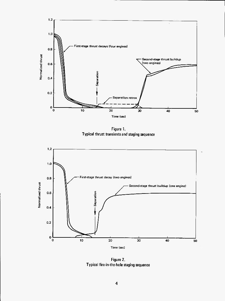
Transient loads from thrust excitation occur during the jettisoning of a booster stage as a result of thrust decay at shutdown of the stage and thrust buildup at engine ignition of the continuing stage. These transient loads are usually more important and of longer duration than the mechanical and explosive shocks generated by staging devices. In combination with other staging events, thrust transients may give rise to adversely high vibratory responses and stresses, depending on the degree of interaction between the thrust transient and the vehicle’s elastic structure. Although longitudinal vibrations usually will predominate, thrust excitation has in certain instances produced large lateral and torsional responses, either directly or by coupling between longitudinal, lateral, and torsional modes of vibration.
Figure 1 illustrates a sequencing technique used to minimize the interaction between thrust transients and other staging events. The thrust transients are sequenced so that the initiation of staging devices is confined to the relatively low thrust period between thrust decay and thrust buildup.
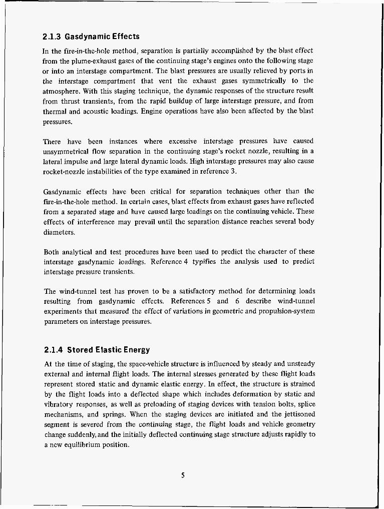
When staging is not confined to a relatively low thrust period, a particularly severe type of loading occurs. For example, the “fire-in-the-hole” staging method causes such loads. In this technique, the engine of the continuing stage is ignited prior to severance of the jettisoned stage. A typical sequence for fire-in-the-hole staging is illustrated in figure 2.
3
1.2
1 .o
0.8
0.6
0.4
0.2
0 0
1.2
1 .o
0.8
0.6
0.4
0.2
0 0
First-stage thrust decays (four engines)
Separation retros
First-stage thrust decays (four engines)
Second-stage thrust buildup
Separation retros
10 20 30 40 50
Time (sed
Figure 1. Typical thrust transients and staging sequence
Second-stage thrust buildup (one engine)
I I
10 20 30 40 50
Figure 2. Typical fire-in-the-hole staging sequence
4
2.1.3 Gasdynamic Effects
In the fire-in-the-hole method, separation is partially accomplished by the blast effect from the plume-exhaust gases of the continuing stage’s engines onto the following stage or into an interstage compartment. The blast pressures are usually relieved by ports in the interstage compartment that vent the exhaust gases symmetrically to the atmosphere. With this staging technique, the dynamic responses of the structure result from thrust transients, from the rapid buildup of large interstage pressure, and from thermal and acoustic loadings. Engine operations have also been affected by the blast pressures.
There have been instances where excessive interstage pressures have caused unsymmetrical flow separation in the continuing stage’s rocket nozzle, resulting in a lateral impulse and large lateral dynamic loads. High interstage pressures may also cause rocket-nozzle instabilities of the type examined in reference 3.
Gasdynamic effects have been critical for separation techniques other than the fire-in-the-hole method. In certain cases, blast effects from exhaust gases have reflected from a separated stage and have caused large loadings on the continuing vehicle. These effects of interference may prevail until the separation distance reaches several body diameters.
Both analytical and test procedures have been used to predict the character of these interstage gasdynamic loadings. Reference 4 typifies the analysis used to predict interstage pressure transients.
The wind-tunnel test has proven to be a satisfactory method for determining loads resulting from gasdynamic effects. References 5 and 6 describe wind-tunnel experiments that measured the effect of variations in geometric and propulsion-system parameters on interstage pressures.
2.1.4 Stored Elastic Energy
At the time of staging, the space-vehicle structure is influenced by steady and unsteady external and internal flight loads. The internal stresses generated by these flight loads represent stored static and dynamic elastic energy. In effect, the structure is strained by the flight loads into a deflected shape which includes deformation by static and vibratory responses, as well as preloading of staging devices with tension bolts, splice mechanisms, and springs. When the staging devices are initiated and the jettisoned segment is severed from the continuing stage, the flight loads and vehicle geometry change suddenly, and the initially deflected continuing stage structure adjusts rapidly to a new equilibrium position.
5

The magnitude of the transient response from this adjustment is determined by the amount of stored elastic energy released during the separation. The internal stresses generated by the release of this energy are usually quite small; however, as noted in reference 1 large lateral elastic responses may occur at staging, owing to the release of stored elastic energy. Responses are more severe in a long flexible space vehicle that is deflected by atmospheric disturbances. Failure of one early launch vehicle was, in fact, attributed to this cause.
2.1.5 Control and Aerodynamic Forces
During staging, the space-vehicle structure may be loaded by control and aerodynamic forces, generated by attitude-control-system commands or aerodynamic disturbances. These forces can cause large lateral loads when the engines of the continuing stage are ignited during the staging sequence and when the engines or the control surfaces are deflected to large angles by the continuing stage’s guidance and control equipment (ref. 7).
During staging in the sensible atmosphere, the continuing-vehicle structure is subjected to a new distribution of aerodynamic forces. The change in aerodynamic loading is a result of changes in geometry and of changes in the distance between the continuing stage and the jettisoned segment. Analytical determination of this aerodynamic loading is difficult; the best method of obtaining information is through wind-tunnel tests, such as those described in references 8 and 9. Evaluation of wind-tunnel test data is limited by difficulties of scaling and simulation; however, interpretation of wind-tunnel data by existing techniques usually leads to conservative results.
To analyze the dynamic response to the gust and wind-shear environments, the alterations in structural dynamic characteristics of the vehicle caused by the staging sequence must also be considered. There are numerous satisfactory general approaches for determining aerodynamic loads, such as that described in reference 10. Many of these approaches, however, are applicable only in a limited range of variables, such as low Mach number, so that their application to a particular staging-load problem depends on the vehicle’s geometry and the environmental conditions existing at staging. Some indication of the environmental conditions associated with gust and wind-shear loads is given in reference 1 1.
2.2 Methods of Analysis General analytical methods for determining the dynamic response of structures subjected to transient loads are discussed in the monographs on mechanical shock
6
response analysis and on natural vibration modal analysis. For analysis of staging, two types of analytical investigations are usually performed: ( 1) separation analysis and (2) staging-loads analysis.
Separation analysis is used to predict whether or not the stages will separate without collision, and whether the stability of the continuing vehicle will be affected by staging. Typical separation analyses are presented in references 12 and 13.
Staging-loads analysis is made to determine whether the vehicle’s structure can withstand the staging loads. If these staging loads are high, they can become a critical design condition. When this occurs, the usual practice is for the designer to change the staging sequence or operation to reduce the staging loads, so long as these changes still allow satisfactory separation.
Dynamic responses to the load inputs are computed in these analyses. The responses are obtained by formulating a mathematical model of the structure and solving the appropriate set of differential equations of motion. Staging equations can become complex, and it is possible, although not usual, to find mathematical models with many rigid-body and elastic degrees of freedom, and with complete coupling of longitudinal, lateral, and torsional motions.
2.2.1 Mathematical Model
For most staging-loads problems studied to date, uncoupled longitudinal, lateral, or torsional dynamic-mathematical models have been used. However, under certain circumstances (such as in an unsymmetrical staging operation), coupled motions can lead to significant stresses that must be considered in analysis. Longitudinal, lateral, and torsional models for solid- and liquid-propellant space vehicles, and methods used to determine the dynamic characteristics needed for analysis of vehicle responses are discussed in references 14 to 16, and in the monograph on natural vibration modal analysis.
For staging-loads analysis, the simpler types of mathematical models are used. The most frequently used model is the lumped-parameter model, in which the space vehicle’s structural system is represented by a series of lumped masses connected by flexible elements. Valid results with this model have been obtained when the complex structure is satisfactorily idealized and appropriate boundary conditions are included. These boundary conditions include the effects of rails, rollers, sway braces, pin pullers, springs, and bolts associated with the staging devices.
7

The accuracy of the results obtained with the lumped-parameter model decreases with increases in the high-frequency content of the load inputs. An explosive device is a typical example of a load input which cannot be satisfactorily handled by the lumped-parameter approach.
2.2.2 Staging-Loads Analysis
Transient stresses, forces, and moments are determined by computing the response of the model to the load inputs. Essentially, the solutions desired are the responses of two or more multidegree-of-freedom dynamic systems (the continuing space vehicle and the jettisoned segments) to prescribed external and internal load inputs. General procedures for predicting transient responses may be grouped into three basic analytical methods: the direct method, the normal-mode method, and the shock-spectra method. These various methods are applicable to longitudinal, lateral, and torsional responses.
In the direct method, solutions are obtained in the coordinate system of the original mathematical model. The normal-mode method differs from the direct method in that the coordinate system of the original mathematical model (which is coupled) is mathematically transformed to an uncoupled (orthogonal) set of coordinates (normal vibration-mode coordinates). Both methods have been used with staging-loads inputs in the form of time histories or Fourier spectra. The normal-mode method, however, is used when the input is defined as shock spectra. Numerical techniques for the solution of differential equations developed in the direct method are contained in reference 17; a good treatment of the normal-mode method is presented in reference 18.
In conjunction with the normal-mode method, the shock-spectra method as discussed in references 19 and 20 is used to calculate the absolute response maxima of the normal modes to a staging-load input. The method always leads to an upper bound of response and is particularly useful for estimating internal stresses to assess the relative severity of different staging-load inputs. A concise discussion of the shock-spectra method is provided in reference 2 1.
Staging-loads analyses depend to a great extent on the experience gained from previous flights with similar staging systems. The data obtained from these flights have revealed several specific staging-loads problems which are summarized in table A-I1 in the Appendix. Also, the analyses and tests customarily used in evaluating the load sources for design are described in the table.
8
2.3 Tests The analytical techniques for staging analysis have been supplemented by extensive experimental programs. Some of these programs have provided specialized data on the character of the individual load sources, while other tests using full-scale segments of hardware have verified that a particular staging system will adequately perform its separation function.
Most of these staging tests have been conducted to evaluate separation mechanics and the integrity of equipment and equipment-support structures. The ability of interstage and tank structures to withstand anticipated staging loads has also been determined from extrapolation of existing test data. An example of such an extrapolation for pyrotechnic shock loads is presented in reference 22. These shock loadings have been measured up to 10 000 g over a frequency range of 5000 Hz. Although these extremely high-level, high-frequency , and short-lived disturbances are usually dissipated locally, shock loadings of significant intensity can still travel substantial distances and cause damage (ref. 23). Such loadings are to be considered in the planned monograph on explosive shock. Explosive shock loads have usually been evaluated through ground tests, although the statistical-energy method described in reference 24 has been applied in estimating these loads.
Staging loads can cause shock, vibration, acoustic loading, fragmentation, and high temperatures, which in turn can cause failures or temporary malfunction of secondary structure and equipment. It is difficult to predict the effect of these loads on secondary structure and equipment. Their capabilities are usually demonstrated in ground tests using functional components in environment-simulating flight conditions.
Facilities for performing staging tests are quite varied. Wind-tunnel tests such as those reported in reference 9 and high-altitude vacuum-chamber tests such as those reported in reference 25 have been particularly useful in providing an environment in which complex staging phenomena that are not amenable to analysis can be studied. Staging loads have also been obtained through elaborate ground tests, using fixtures such as those mentioned in reference 26.
When the load source and structural paths can be clearly identified, the simulation technique for conducting functional staging tests is straightforward. The testing problem is considerably more complicated when load sources are varied or when multiple interactions occur (such as structure, aerodynamic, and thrust interactions), or when loading is not unidirectional. Simulation of these multiple interactions can be obtained only through full-scale tests of large portions of primary structure.
9

Realistic mechanical shock and explosive shocks are difficult to simulate without actual shock-load sources. In lieu of actual shock environment, various means have been used to simulate shock loading. The methods employed include generation of multiple-decaying sinusoids which simulate the shock spectrum. These sinusoids are used for an inverse computer solution to obtain voltages for driving the test shakers (refs. 27 and 28).
Confidence in the use of a staging concept to avoid or minimize such structural problems as those described in table A-I1 has been achieved by careful attention to testing details and by continued analytical support of staging tests. The typical tests conducted to examine staging-loads problems are also summarized in table A-11.
3. CRITERIA
3.1 General
The structural design of a space vehicle shall adequately account for the combined effects of staging loads and all other natural and induced loads occurring at the time of staging.
3.2 Guides for Compliance
3.2.1 Staging-Loads Ana lysis
Staging-loads analysis shall, as a minimum, account for loads resulting from :
0 Operation of staging devices. 0
0
0
0
Thrust transients from shutdown or ignition of stage engines. Gasdynamic effects of stage engines or retrorockets. Stored elastic energy in the structure at separation. Vehicle flight loads from aerodynamic and control effects.
Consideration shall also be given, where applicable, to secondary loads from spin interactions, unsteady aerodynamic forces, and liquid-propellant motions, or similar sources.
10

1
3.2.1.1 Load Definition
The dynamic inputs of force and motion caused by staging-loadssources shall be derived from experimental data obtained from the vehicle under study or from similar vehicles, or, when applicable data are not directly available, from a logical extrapolation of related experimental data.
3.2.1.2 Methods of Analysis
The analysis of staging loads shall account for the stresses, forces, and motions imposed on the structure by the staging-loads sources. The analysis shall employ multidegree-of-freedom models incorporating longitudinal and, as needed, lateral and torsional dynamic properties of the continuing space vehicle and of the jettisoned segments .
3.2.2 Tests
Tests to verify structural integrity under staging loads shall use either actual space-vehicle structure and configurations, load inputs, and environmental conditions that influence the structural responses to the staging loads or conservative approximations of the structure, configuration, and conditions.
3.2.3 Criteria for Compliance
Compliance shall be shown by analysis and/or tests for all staging loads except those caused by explosive shock; for staging loads caused by explosive shock, compliance shall be shown by test. In lieu of analysis or test, analytical or experimental results that have been validated on a similar configuration may be used in a conservative manner to show compliance.
4. RECOMMENDED PRACTICES
The following basic approaches are recommended for the design of space-vehicle structures to enable them to withstand staging loads:
1. For staging operations that do not involve explosive shock, the vehicle’s structural adequacy should be assessed by analysis, or by tests, or by both. Initially, this assessment should be based on conservative, simplified modeling and analytical methods. Load sources that are clearly not a design problem can then be eliminated from consideration. (No structural problems are usually found in analysis of nonexplosive separation devices, such as
11

V-band clamps, springs, soft joints, pin pullers, or frangible diaphragms.) When a possible structural design problem is indicated, detailed analyses or tests should be conducted to ensure that the design is adequate, or to ascertain those changes required in the vehicle’s structure or staging system to make the design adequate.
2. For staging operations that involve explosive shock from primacord, shaped charges, or explosive bolts, the vehicle’s structural adequacy should be assessed by tests. As an alternative approach, the vehicle’s structural adequacy should be assessed by comparison with previous analysis or tests on similar vehicles and staging systems.
In pursuing the recommended approach, the following steps should be taken:
1.
2.
3.
The potential sources of staging loads should be identified and assessed, and the load inputs should be defined.
The structural responses to these loads should be determined by devising mathematical models to represent the dynamics of the space-vehicle structure and by obtaining the responses of these models to the load inputs.
When warranted, tests should be conducted using representative structural components or complete structures to demonstrate structural adequacy.
4.1 Staging-Loads Analysis
4.1.1 Load Definition
Dynamic inputs from load sources should be defined by time histories. The load inputs should be taken directly from transient-motion data collected during representative ground, wind-tunnel, or flight tests, or when test data are not readily available (as in the development phase of a new staging system), from similar systems.
Acceleration time histories of selected points on the vehicle’s structure should be measured with acceleration transducers (accelerometers). Care should be taken to ensure that the transducers used have sufficient bandwidth, are properly mounted, have small mass in relation to the local structure, and will not be overstressed during the tests. Pertinent information on the use of accelerometers should be obtained from the transducer manufacturer.
12

For shock-type inputs, the time histories should be put in the form of either shock spectra or Fourier spectra. Reduction of shock-acceleration time histories to shock spectra or Fourier spectra will in many cases require a complex analysis of data. It is therefore recommended that the procedures required to calculate and plot these spectra be programmed on a digital computer.
The analysis should also consider structural constraints which include changes in the geometry of the staging configuration and the variable mechanical aspects of the staging devices, such as their initiation times and structural interactions. Geometric constraints on boundary conditions should be based on the operational characteristics of the staging system and should include the results of a separation analysis to determine the spatial and temporal relationships between structural segments.
4.1.2 Methods of Analysis
A lumped-parameter mathematical model of the vehicle’s structure and staging system of the type described in references 14 to 16 is recommended. If possible, this model should be linear; however, for staging systems with significant nonlinearities (e.g., large angular guide-rail motions or aerodynamic forces that depend strongly on displacement), a nonlinear lumped-parameter model should be derived. In the development of a model, the possibility of interactions among longitudinal, lateral, and torsional motions should be considered.
If a linear lumped-parameter model can be developed, its response to the load sources should be initially examined by the shock-spectra method. For the shock-spectra method, it is necessary to compute the normal vibration modes of the lumped-parameter model. Use of the shock-spectra method in conjunction with the normal-mode method is discussed in references 19 to 21 and in the planned monograph on mechanical shock response analysis. This approach is a conservative means of determining response stresses, and should be used to indicate which load sources represent actual problems.
A more detailed analysis should be performed when stresses calculated by the shock-spectra method are found to be excessive, when the system has significant nonlinearities that cannot be easily approximated by a linear model, or when structural interactions among longitudinal, lateral, and torsional motions are clearly important. This detailed analytical determination of the transient stresses should be based on either the direct method (ref. 17) or on the normal-mode method (ref. 18) of solving for structural response. Both forms will yield precise response solutions for external and internal load sources applied as input data in the form of time histories or Fourier spectra, and for boundary conditions in the form of spatial and temporal mathematical
13

constraints. The direct method must be employed when significant nonlinearities are to be considered. The typical analytical requirements presented in table A-I1 are suggested as a basis for solving the specific load problems summarized in the table.
Computations employing Fourier spectra as input should be made on a digital computer. Either digital or analog computers can be used for the normal-mode or direct method. The analog computer, however, is recommended when significant nonlinearities are considered.
4.2 Tests
Staging-load tests on structural assemblies should be performed to verify structural integrity when an analytical assessment indicates that such tests are required or when previously validated analytical or experimental results on a similar configuration are not available. In the tests, the actual staging sequences and loads should be simulated under proper environmental conditions. When the complete vehicle is not simulated, the load sources may be synthesized by the methods described in references 27 and 28.
When data are required to supplement the staging-loads analysis, it is suggested that the staging-system ground-test program be expanded to include the measurement of transient responses from loads. Staging tests without complete vehicle simulation will require analytical support in order to determine how to extrapolate these test results to actual vehicle responses.
14
APPENDIX STAGING DEVICES AND STAGING-LOADS PROBLEMS
Tables A-I and A-I1 are presented on the following pages. Various types of staging devices are summarized in table A-I, which includes an evaluation of each device and its particular design consideration; table A-I1 summarizes the staging-loads problems encountered in actual flight.
15

, Table A-I. CURRENT STAGING DEVICES
Devices
RELEASE MECHANISMS
Mild detonating fuse [MOF)
Primacord. an explosive cord surrounded by a nonmetallic sheath, rupturesthe structure upon activation
Flexible linear-shaped charge (FLSC)
Metallic sheath covers explo. sive core; intensity of explo- sion is focused along a line by the shape of the core and the sheath; severs the Structure unon activation
V-band clamps
Clamping device mounted in tension over matching fittings; at release, the device is cut and separated from the fittings
Explosive bolts, nuts
Notched bolt or nut containing an internal explosive charge; upon activation. stress con- centration in combination with tension load causes fracture at restricted or notched sections
Pressure-failure bolts
A type of explosive bolt designed to smooth the pres- sure-buildup effects; consists o f a sealed necked-down bolt containing an internal explo. sive charge; upon activation. internal pressure causes tension failure at necked-down section
Advantages
Lightweight; reliable; low induced tipoff moments; con- tinuous structural application with high-strength joint
Lightweight; reliable; low induced tipoff moments; con- tinuous structural application with high-strength joint
High bending moment and nrength capabilities; reliable; easy assembly of vehicle stage
Lightweight; off.the.shelf item; high reliability
Minimum fragmentation; positive separation force
Disadvantages
Causes fragmentation, detona- tion shock, blast-wave damage, and high localized loadings; requires destructive testing
Causes fragmentation, detona- nation shock, blast-wave damage, and high localized loadings; requires destructive testing
Excessive weight; high cost; special finishes needed; possible unsymmetric release and binding
Fragmentation damage; access for torquing bolts or nuts and installation of squibs required
Sealing requirement; presence of detonation shock
Design considerations
Joint characteristics and detail design directly influence the shock magnitude (i.e.. type of explosive used, size of charge, shell thickness and material to be cut, and design backup ring); consider- able ground testing is required; a major concern is the effect on adjacent equipment
Joint characteristics and detail design directly influence the shock magnitude (i.e., type of explosive used, size of charge, shell thickness and material to be cut, and design of backup ring); con- siderable ground tegt is required; a major concern is the effect on adjacent equipment
Problems include design of bandlclamp segments, attach- ment ring and alignment pins, bolt torque for proper band preload, seating of clamps during assembly. possible effects of collision between bandlclamp segments and con- tinuing stage during release and separation;functional and demonstration ground tests are required
Fragmentation is minimized by proper containment of debris; reliability is increased by use of parallel detonation systems; laboratory testsare required; bolts. heads, and nuts should be properly torqued. loaded only in tension and shear, and be subjected to flight-operating environments
Fragmentation is minimized by proper containment of debris; reliability is increased by use of parallel detonation systems; laboratory tests are required; bolts, heads, and nuts should be properly torqued. loaded only in tension and shear, and be subjected to flight.operating environments
16

ICont'dl
Pin puller or pusher unit
Pin engages bolt stud or con- necting link; gas pressures generated in a sealed unit by firing of squibs cause pin t o be pulled or pushed from its hole in the stud or connection
Frangible diaphragm
Diaphragm coupler between stages is broken by the engine exhaust upon ignition of the continuing stage
Soft joint
Stages are freely connected together at point of repara- tion until drag of expended stage or ignition of continu ing stage causes separation
2. SEPARATION-IMPULSE MECHANISMS I
I Thrust reversal
Forward.directed solidmcket motor.prenure release ports or orifices reverse the booster stage thrust upon port opening at stage burnout; forward-directed exhaust gases also impart some separation impulse to continuing stage
Sprinps
Helical or lead springs supply separation impulse upor elimination of connection between staging bodies
Stage ignition ("fire in the hole")
Upper-stge engines are ignited just before disengage- ment of connection between stages. causing the interstage cavity to be pressurized by the exhaust gases; the pressure Bxerts separating forces on each stage
Table A-I.-Continued CURRENT STAGING DEVICES
Advantages Disadvantages
No fragmentation; good load path
Alignments critical: use of more than one unit requires careful synchronization of performance to avoid eccentric release; sealing requirements
Simple; reliable; no fragmenta. t ion damage to continuing stage; no separate ignition source required
Excessive weight; high cost; low bendingmoment capability; limited access for inspection; interstage design to limit pressure; no coasting of con- tinuing stage by itself
Highly reliable; low cost Limited applications; does not accommodate maneuvering or bending moments
Positive separation force and thrust decay
Unequal or unsymmetric reverre thrust; time delays; pressure. release port-detonation shock; thrust-reversal shock; residual chamber pressure
Reliable; positive separation Precise alignment required; force; no fragmentation; low possible source of tipoff shock moments; excessive weight
Eliminates coasting time; upper-stage propulsion system also furnishes separation impulse
Severe environments (shock. pressure, acoustic inputs, and temperature) generated; possi. ble rupture of forward dome of burnedmt stage with wbse. quent explosion; plume may reflect from burnedmt stage and heat the continuing stage
17
Design conriderations
Reliability is increased by the use of parallel detonation systems; design details include align. ment and matching of force. displacement. and time characteristics of the pin uniis; operaiional capability is determined by tests which must include a simulated flight environment
Thread shapes and diaphragm slots must be properly designed to ensure rupture and disengagement and provide access for inspection; the diaphragm must be designed to release at an interstage pres. sure below a value that would choke engine nozzle and cause malfunction
Friction and binding effects need to be minimized by design
Gas exhaust plumes and reverse- thrust iransienfs can heat, move, or load the continuing stage; designs must ensure that there are no collisions between the continuing stage and such fall.away articles as port covers
A large number of springs should be available to permit selection of matched sets; designs should provide for lateral stability of all springs by suitable guides; detailed spring measurements and ground separation tests are required
Intentage venting areas (blast doors) must be adequate to preclude damage from shock. induced nozzle instability or unsymmetrical flow separation that can choke the continuing stage motors; wind.tunnel testing is required to estab. lish whether choking is a problem: design environments must include thrust transient, and pressure, acoustic, and temperature conditions at staging: thorough analysis must be conducted to establish motions and pressure buildup

I Dwim I
2. SEPARATION-IMPULSE MECHANISMS (Cont'dl
Auxiliary rockets
' Cold, hot.gas or solid propellant rockets which fur. nish separation forces to the jettisoned segment andlor the continuing stage
C8ptive pressure
Intentage cavity i s sealed so that internal pressure remains at or near original value; then, at staging, captive pressure furnishes a separation impulse to each stage
Aerodynamic
Lif t andlur drag devices remove the jettisoned segment from the vicinity of the con- tinuing stage
Gar.opented pistons
Piston is forced against c o n
3. AUXILIARY DEVICES
Rails, rollers
Structural members which allow guided separation of stages
Sway braces
Mechanical linkages which allow the expended stage to be moved into the air stream and pivoted away from the continuing stage; used for "strapon" stage disposal
Table A-I.-Concluded CURRENT STAGING DEVICES
Positive separation force; reliable
Makes use of existing pressure differentials
Uses available energy source: no fragmentation or shock
Positive separation; no fragmentation
Prevents collision during; oxtraction; stabilizes sepa- ration and stage alignment
No fragmentation or shock; assures clearance of expended stage from continuing stage
Added weight; additional system decreases overall reliability; contamination andlor jet impingement; to evoid eccentric reparation, rockets must be carefully aligned and thrusts closely matched
Use depends on reliable and effective pressuresealing capability and altitude of staging; there islittle con- trol over actual delivered separation impulse
Continuing stage influenced by flow-interference effects; system sensitive to conditions at staging
Sealing requirement; to avoid eccentric separation, use of more than one piston requires careful synchronization of performance
Contact forces and friction act on both stages during extraction; rail loads or "twang" loads; possible hangup or binding effects
High concentrated loadings; possible binding or local damage effects
Design considerations
Auxiliary rockets have severe alignment problems and must be matched where multiple rockets are used
Pressure seal must be sufficient for operating environments; wind.tunnel (including high- altitude chamber) staging tests are required; structural integrity with the pressure environment may be a design constraint
Detailed staging analyses must be conducted to describe the motions of both stages during separation; these analyses must beverified by tunnel tests
Use of parallel detonation systems for increased relia- bility; laboratory tests required; alignment; matching of each piston's force, diglacement, and timeoperating character. istics necessary; effects of flight-operational environ. ments; pressure seals
Analyses are conducted to pre- dict the separation motions, and verified by ground tests
Interaction of jettisoned com. ponents and aerodynamic forces is a major design considera lion; during this process, the continuing stage i s subjected to high loads
18

Table A-11. STAG I N G- LOADS PR 0 B LEMS
Important p i ~ m e n n Typical tsm
1. J m i e n of slructurn
Severe local loads Separation impuk; t ipo f f moments: disconnect forces; offsets: parameter tolerances: local geometry; residual thrust; and initial conditions
Functional-t ype ground tests, employing either full-scale or modeled staging devices; scalemodel wind-tunnel investigations
Shockqmtra analysis of local dynamic and rigid.body loading, including mechanical- and explosive shock considerations
2. Ignition of continuing Ngs
Severe dynamic and envirbn. mental effects on both the continuing and.the jettisoned Ifages
Longitudinal dynamic properties of structural syp temr; thrust transients; dynamic pressure; temperature; and acoustic loadings
Complete loads analysis for both stages, primarily longi. tudinal analysis, although may raquire lateral and tor- sional coupling; flexible and rigidhody effects included
Wind-tunnel tests to dafine aerodynamic intaractions and gasdynamic environments; ground firing tests
3. Engine cutoff 8nd mro f i r ing before Ifauing
Transient dynamic loads and plumegasdynamic effects on the continuing stage
Malfunction conditions; misalignments; parameter tolerances: thrust and plume gasdynamic characteristics; initial conditions; longi- tudinal dynamic propenies of structural system
Gasdynamic analyses; rigid- body motion studies; longi- tudinal and lateral dynamic- response analysis: analysis of local attachment shock loads; tonional-loads analysis for multipleengine vehicles
Ground tests and high.altitude tunnel tests of cutoff and retrosystem operation
4. Thermil emironmant
Expansion andlor out.of. roundness. causing binding of interface surfaces
Separation tests, including temperature simulation end thermal transiants
Amount of insulation; friction and thermal characteristics of separating surfaces; structural design of interface
Detailed thermal and sepe ration analysis, including friction end hangup forces
6. Separation in the atmorphera
Interactions b e w e n the flexible vehicle and its guidance and control system durirg staging, causing adverse loadings and possible loss of control of the continuing stage
Lateral bending modes end Josh modes; trajectory and related flightmechanics quantities: gusts and wind shears; initial conditions; control-system dynamics
Lateral generalized dynamics analyses, including simule lions of the guidance and control system, vehicle's rigid. and flexible-body degrees of freedom, and such siinifiiant events as a step change in parameters a t staging
Full.scele or model ground vibration t a m to obtain vehicle's laterel dynamic characteristics
8. Spin interntion
Large local loadings at spin. system attachment and large radial and tangential loading on structural and electrical components
FunctionaLtypa ground tests; vacuumchamber tests; possibly wind-tunnel tests if spinning occurs in the atmosphere
Spin forces of impulsas; initial conditions; misalign. ments; torsional dynamic properties of structural system; dynamic balance
Local4oading analysis: torsional.dynamics analysis
1. Liquid~propellant motions
Fluid compressibility. tank. wall elasticity, and vehicle's longitudinal dynamic coupling effects produce high hydro- static pressures and loads; possible impact of residual propellants on forward domes of tanks, causing tank rupture and explosion: forward dome of expended stage rupture at "fire in the hole" from huh interstage pressures and temperatures
Longitudinal dynamic proper. ties of vehicle and i ts propel. lant-system thrust transients; intamage pressures and temperatures
Longitudinal dynamic- response analysis; propellant.impact loads analysis on domes
Propellant-impact simulations
19

REFERENCES
1. Hahn, P.G. : Structural Design Criteria for Stage Separation (U). ASD-TR-6 1-67 1 , 1963. (Confidential)
2. Domingues, G.D.; and Rubin, S . : Survey of In-Flight Separation Systems (U). Rept. TOR-269(4106-01)-15, Aerospace Corp., Oct. 26, 1964. (Confidential)
3. Tuovila, W.J.; and Land, N.S.: Experimental Study of Aeroelastic Instability of Overexpanded Rocket Nozzle Extensions. NASA TN D-447 1, 1968.
4. Smoot, L.D.: Prediction of Interstage Pressure in Multistage Solid Propellant Rocket Systems. AIAA J., vol. 1, no. 10, Oct. 1963, pp. 2361-2365.
5 . Mitchell, G.A.: and Cubbinson, R.W.: Interstage Pressures and Forces During High-Altitude Stage Separation with Operating Upper-Stage Engine (U). NASA TM X-870, 1963. (Confidential)
6. Binion, T.W.: Jet Interference During Stage Separation at Very High Altitude. AEDC-TDR-64-89, May 1964.
7. Bohne, W.R.; Clingan, B.E.; et al.: The Dynamic Response of Advanced Vehicles. WADD TR-60-518, Sept. 1960.
8. Wasko, R.A.: Experimental Investigation of Stage Separation Aerodynamics. NASA TN D-868, 1961.
9. Hamner, R.L. : Experimental Investigation of Missile Stage Separation with an Operat ing Second Stage Jet and Supersonic External Stream (U). AEDC-TDR-63-125, July 1964. (Confidential)
10. Clingan, B.E.; Gates, R.M.; and Andrews, J.S.: Dynamic Loads During Booster Flight. ASD-TDR-63-302, May 1963.
1 1. Daniels, G.E.; Scoggins, J.R.; and Smith, O.E.: Terrestrial Environment (Climatic) Criteria Guidelines for Use in Space Vehicle Development, 1966 Revision. NASA TM X-53328,1966.
21

12.
13.
14.
15.
16.
17.
18.
19.
20.
21.
22.
23.
24.
Chubb, W.B.: The Collision Boundary Between the Two Separating Stages of the SA-4 Saturn Vehicle. NASA TN D-598, 1961.
Peotler, G.; and Bloomgren, P.: Program 624A Standard Space Launch Vehicle Staging Dynamics Analysis Report, Flight Test Plan VIII. Rept. SSD-CR-65-35, Martin Marietta Corp., Denver Division, Feb. 1965. (Available from DDC as AD 458233.)
Paddock, G.B.: Dynamic Stability of Space Vehicles. Vol. I - Lateral Vibration Modes. NASA CR-935, 1967.
Staley, J.A.: Dynamic Stability of Space Vehicles. Vol. I1 - Determination of Longitudinal Vibration Modes. NASA CR-936, 1967.
Gieske, R.; Schuett, R.; and Lukens, D.: Dynamic Stability of Space Vehicles. Vol. I11 - Torsional Vibration Modes. NASA CR-937, 1967.
Fox, L. : Numerical Solution of Ordinary and Partial Differential Equations. Addison-Wesley Pub. Co., Inc., 1955.
Hurty, W.C.; and Rubinstein, M.F.: Dynamics of Structures. Prentice-Hall Inc., 1964.
Biot, M.A.: A Mechanical Analyzer for the Prediction of Earthquake Stresses. Bull. Seismological Society of America, vol. 3 1 , no. 2, Apr. 1941 , pp. 15 1-1 7 1.
Biot, M.A. : Analytical and Experimental Methods in Engineering Seismology. Trans. ASCE No. 108, 1943, pp. 365-385.
Harris, C.M.; and Crede, C.E., eds.: Shock and Vibration Handbook. Vol. I, ch. 8, and Vol. 11, ch. 23. McGraw-Hill Book Co., Inc., 1961.
Ikola, A.; and Wherry, M.: LMSC Pyrotechnic Shock Experience. Papef no. 6607 17, SAE Aeronautics and Space Engineering and Manufacturing Meeting, Oct. 1966.
Hines, D.E.: Generation and Propagation of Stage Separation Shocks in Missiles and Space Vehicles. Proc. of the Inst. of Environmental Sciences, 1964.
Manning, J.E.; and Lee, K.: Predicting Mechanical Shock Transmission. The Shock and Vibration Bull. No. 37, Part 4, Jan. 1968.
22
25. Lang, W.E.; and Honeycutt, G.H.: Simulation of Deployment Dynamics of Spinning Spacecraft. NASA TN D-4074, 1967.
26. Penzes, L.E. : Frequency, Dynamic Response and Jettison Analyses for Jettisonable Payloads Shrouds, with Application to the Orbital Astronomical Observatory (OAO) Fairing. Proc. of the Inst. of Environmental Sciences, 1966 Annual Technical Meeting (San Diego, Calif.), 1966.
27. Painter, G.W.; and Parry, H.J.: Simulating Flight Environment Shock on Electrodynamic Shakers. The Shock and Vibration Bull. No. 33, Part 3, Mar. 1964.
28. Trubert, M.R.: Use of Ranger Flight Data in the Synthesis of a Torsional Acceleration Transient for Surveyor Vibration Qualification Testing. NASA CR-83 1 10, 1966.
23
SP-800 1
SP-8002
SP-8003 SP-8004 SP-8005 SP-8006
SP-8007
. SP-8008 SP-8009 SP-80 10 SP-80 1 1
SP-80 12 SP-80 13
SP-80 14 SP-80 1 5
SP-80 16
SP-80 1 7
SP-80 18
SP-80 1 9
SP-8020 SP-802 1
NASA SPACE VEHICLE DESIGN CRITERIA MONOGRAPHS ISSUED TO DATE
(Structures)
(structures)
(Structures) (Structures) (Environment) (Structures)
(Structures)
(Structures) (Structures) (Environment) (Environment)
(Structures) (Environment)
(Structures) (Guidance and Control) (Guidance and Control) (Environment)
(Guidance and Control) (Structures)
(Environment) (Environment)
Buffeting During Atmospheric Ascent, May 1964 - Revised November 1970
Flight-Loads Measurements During Launch and Exit, December 1964
Flutter, Buzz, and Divergence, July 1964 Panel Flutter, July 1964 Solar Electromagnetic Radiation, June 1965 Local Steady Aerodynamic Loads During Launch
Buckling of Thin-W alled Circular Cylinders,
Prelaunch Ground Wind Loads, November 1965 Propellant Slosh Loads, August 1968 Models of Mars Atmosphere (1 967), May 1968 Models of Venus Atmosphere (1968), December
Natural Vibration Modal Analysis, September 1968 Meteoroid Environment Model - 1969 [Near
Earth to Lunar Surface], March 1969 Entry Thermal Protection, August 1968 Guidance and Navigation for Entry Vehicles,
Effects of Structural Flexibility on Spacecraft
Magnetic Fields - Earth and Extraterrestrial,
Spacecraft Magnetic Torques, March 1969
and Exit, May 1965
September 1965 - Revised August 1968
1968
November 1968
Control Systems, April 1969
March 1969
B u c k l i ng of Thin-Walled Truncated Cones,
Mars Surface Models (1 968), May 1969 Models of Earth’s Atmosphere (1 20 to 1000 km),
September 1968
May 1969
25

SP-8022 SP-8023 SP-8024
SP-8025
SP-8026
SP-8027
SP-8028
SP-8029
SP-8030
SP-803 1 SP-8032
SP-8033
SP-8034
SP-8035 SP-8036
SP-8037
SP-8038
SP-8040
SP-8042 SP-8043 SP-8044 SP-8045 SP-8046
SP-8047
SP-8050
(Structures) (Environment) (Guidance and Control) (Chemical Propulsion) (Guidance and Control) (Guidance and Control) (Guidance and Control) (Structures)
(Structures)
(Structures) (Structures)
(Guidance and Control) (Guidance and Control) (Structures) (Guidance and Control) (Environment)
(Environment)
(Structures)
(Structures) (Structures) (Structures) (Structures) (Structures)
(Guidance and Control) ( S t ru c tu res)
Staging Loads, February 1969 Lunar Surface Models, May 1969 Spacecraft Gravitational Torques, May 1969
I
Solid Rocket Motor Metal Cases, April 1970
Spacecraft Star Trackers, July 1970
Spacecraft Radiation Torques, October 1969
Entry Vehicle Control, November 1969
Aerodynamic and Rocket-Exhaust Heating During
Transient Loads from Thrust Excitation, February
Slosh Suppression, May 1969 Buckling of Thin-Walled Doubly Curved Shells,
Spacecraft Earth Horizon Sensors, December 1969
Launch and Ascent, May 1969
1969
August 1969
Spacecraft Mass Expulsion Torques, December
Wind Loads During Ascent, June 1970 Effects of Structural Flexibility on Launch Vehicle
Control Systems, February 1970 Assessment and Control of Spacecraft Magnetic
Fields, September 1970 Meteoroid Environment Model - 1970 (Inter-
planetary and planetary), October 1970 Fracture Control of Metallic Pressure Vessels, May
1970 Meteoroid Damage Assessment, May 1970 Design-Development Testing, May 1970 Qualification Testing, May 1970 Acceptance Testing, April 1970 L a n d i n g I m p a c t A t t e n u a t i o n f o r
Spacecraft Sun Sensors, June 1970
1969
Non-Surface-Planing Landers, April 1970
Structural Vibration Prediction, June 1970
26

SP-8053 (Structures) Nuclear and Space Radiation Effects on Materials, June 1970
SP-8054 (Structures) Space Radiation Protection, June 1970 SP-8055 (Structures) Prevention of Coupled Structure-Propulsion
SP-8056 (Structures) Flight Separation Mechanisms, October 1970 SP-8057 (Structures) Structural Design Criteria Applicable to a Space
SP-8060 (Structures) Compartment Venting, November 1970 SP-806 1 (Structures) Interaction with Umbilicals and Launch Stand,
August 1970
Instability (Pogo), October 1970
Shuttle, January 1971
NASA-Langley, 1971 - 32 27
![[PPT]What is t,n,m staging and summary staging? Staging for... · Web viewWhat are we discussing? What is AJCC Staging Purpose of staging General rules for clinical and pathological](https://img.pdfslide.us/doc/110x75/5b1cc7cc7f8b9a8c5a8ba42e/pptwhat-is-tnm-staging-and-summary-staging-staging-for-web-viewwhat.jpg)