Embed Size (px)
Citation preview

Prepared for:
Department of Defence
Environmental Impact Management National Contamination Management Unit Canberra Act 2600
Stage 2 (Part III) Environmental Investigation RAAF Base Tindal Katherine, Northern Territory Draft Final
AECOM
30 September 2009
Document No.: D11029_RPTDraftFinal_30Sep09.doc
FOI 463/17/18 Item 9 Serial # 1
Page 1369 of 4750

FOI 463/17/18 Item 9 Serial # 1
Page 1370 of 4750
Use or disclosure of data contained on this sheet is subject to the restriction on the distribution page of this document.
Commercial in Confidence Stage 2 (Part III) Environmental
Investigation
D11029_RPTDraftFinal_30Sep09.doc
Distribution
Stage 2 (Part III) Environmental Investigation RAAF Base Tindal Katherine, Northern Territory
30 September 2009
Copies Recipient Copies Recipient
1 Melissa Woltmann Defence Project Manager Department of Defence BP3-2-B036 Brindabella Park Canberra ACT 2600
1 AECOM Project File Suite 3, 17-19 Lindsay Street Darwin NT 0800
1 Technical Advisor ERM PO Box 266 South Melbourne Vic 3205
© AECOM * ENSR Australia Pty Ltd (trading as AECOM and hereafter referred to as AECOM) has prepared this document for the purpose
of undertaking a Stage 2 Environmental Investigation and Stage 3 Remediation Design which is described in the Scope of Works section, and was based on information provided by the client, AECOM's understanding of the site conditions, and AECOM's experience, having regard to the assumptions that AECOM can reasonably be expected to make in accordance with sound professional principles.
* This document was prepared for the sole use of the party identified on the cover sheet, and that party is the only intended beneficiary of AECOM's work.
* No other party should rely on the document without the prior written consent of AECOM, and AECOM undertakes no duty to, nor accepts any responsibility to, any third party who may rely upon this document.
* All rights reserved. No section or element of this document may be removed from this document, extracted, reproduced, electronically stored or transmitted in any form without the prior written permission of AECOM.
By ENSR Australia Pty Ltd (trading as AECOM) ABN: 34 060 204 702 Suite 3, 17-19 Lindsay Street Darwin NT 0800 GPO Box 3175 Darwin NT 0801 Ph: +61 8 8981 2698 Fax: +61 8 8981 4565 ____________________________________
Project Environmental Scientist
___________________________________
Senior Environmental Scientist Technical Peer Reviewer: Date: _____________________________________
Principal Remediation Engineer National Service Line Leader - Contaminated Site Services
FOI 463/17/18 Item 9 Serial # 1
s47G s47G
s47G
s47G
s47G
Page 1371 of 4750

Use or disclosure of data contained on this sheet is subject to the restriction on the distribution page of this document.
Commercial in Confidence Stage 2 (Part III) Environmental
Investigation
D11029_RPTDraftFinal_30Sep09.doc
“This page has been left blank intentionally”
FOI 463/17/18 Item 9 Serial # 1
Page 1372 of 4750

Use or disclosure of data contained on this sheet is subject to the restriction on the distribution page of this document.
Commercial in Confidence Stage 2 (Part III) Environmental
Investigation
i D11029_RPTDraftFinal_30Sep09.doc
Contents
GLOSSARY OF TERMS........................................................................................................................ XIX EXECUTIVE SUMMARY............................................................................................................................1 1.0 INTRODUCTION AND BACKGROUND ....................................................................................1
1.1 Introduction ..................................................................................................................1 1.2 Site Description............................................................................................................2 1.3 Objectives ....................................................................................................................2 1.4 Scope of Work .............................................................................................................3
1.4.1 Stage 2 (III) Environmental Investigation .....................................................3 1.4.2 Other Related Activities................................................................................4
1.5 Guidelines and Legislation ..........................................................................................4 1.5.1 NEPM ...........................................................................................................4 1.5.2 National and International Soil Guidelines ...................................................5 1.5.3 National and International Water Guidelines ...............................................6 1.5.4 National Sediment Guidelines......................................................................6 1.5.5 Northern Territory Legislation and Guidelines .............................................7
1.6 Historical Reports ........................................................................................................8 1.7 Report Structure ..........................................................................................................8
2.0 APPROACH TO INVESTIGATION ..........................................................................................11 2.1 Data Review ..............................................................................................................11 2.2 Conceptual Site Model ..............................................................................................11 2.3 Fieldwork Program.....................................................................................................12
2.3.1 Start-up Documentation .............................................................................12 2.3.2 Sample Analysis.........................................................................................13 2.3.3 Contamination Assessment .......................................................................13 2.3.4 Fate and Transport of Contamination ........................................................13
2.4 Risk Considerations...................................................................................................14 2.4.1 Definition of ‘True’ Risk ..............................................................................14 2.4.2 The Contamination Risk Assessment Tool ................................................14 2.4.3 Risk Assessment Workshop ......................................................................21
2.5 Remediation/Management Considerations ...............................................................23 2.6 Reporting ...................................................................................................................23
3.0 SITE CHARACTERISTICS.......................................................................................................25 3.1 Site Identification and Description .............................................................................25 3.2 Historical and Current Site Operations and Features................................................25 3.3 Regional Meteorology................................................................................................26 3.4 Topography and Hydrology .......................................................................................27 3.5 Geology and Hydrology .............................................................................................27 3.6 Surrounding Land Uses.............................................................................................29 3.7 Historical and Current Potentially Contaminating Activities ......................................30 3.8 Areas of Environmental Interest Targeted for the Stage 2 (III)
Environmental Investigations.....................................................................................30 4.0 CONCEPTUAL SITE MODEL ..................................................................................................33
FOI 463/17/18 Item 9 Serial # 1
Page 1373 of 4750

Use or disclosure of data contained on this sheet is subject to the restriction on the distribution page of this document.
Commercial in Confidence Stage 2 (Part III) Environmental
Investigation
ii D11029_RPTDraftFinal_30Sep09.doc
4.1 Potential Contaminants of Concern...........................................................................33 4.2 Environmental Factors Affecting Contaminant Behaviour.........................................35 4.3 Conceptual Site Model ..............................................................................................39
5.0 SITE INVESTIGATION OVERVIEW.........................................................................................47 5.1 Overview....................................................................................................................47 5.2 Data Quality Objectives .............................................................................................47
5.2.1 Step 1 – State the Problem to be Resolved...............................................47 5.2.2 Step 2 – Identify the Decision to be Made .................................................47 5.2.3 Step – 3 Indentify Inputs to the Decision ...................................................48 5.2.4 Step 4 – Define the Boundaries of the Investigation..................................49 5.2.5 Step 5 – Develop a Decision Rule .............................................................50 5.2.6 Step 6 – Specify Limits on Decision Errors ................................................51 5.2.7 Step 7 – Optimise the Design for Obtaining Data ......................................52
5.3 Field Quality Assurance/Quality Control....................................................................52 5.3.1 Tank Integrity Testing QA/QC ....................................................................53 5.3.2 Geophysical Investigation QA/QC..............................................................54 5.3.3 Field Duplicate Samples ............................................................................54 5.3.4 Rinsate Blanks ...........................................................................................56 5.3.5 Trip Blanks .................................................................................................57 5.3.6 Air Sampling Field Blanks ..........................................................................58 5.3.7 Sample Handling ........................................................................................58 5.3.8 Photo-ionisation Detector Screening..........................................................60
5.4 Laboratory Quality Assurance and Control Procedures ............................................61 5.4.1 Monitoring Campaign .................................................................................61
5.5 QA/QC Data Assessment for Supplementary Investigation at NT0065 Fire Station........................................................................................................................63 5.5.1 Supplementary Field QA/QC......................................................................63 5.5.2 Field Duplicates..........................................................................................63 5.5.3 Supplementary Soil Investigation...............................................................64 5.5.4 Supplementary Groundwater Investigation ................................................64 5.5.5 Supplementary Laboratory QA/QC ............................................................64 5.5.6 Summary of Supplementary QA/QC Data .................................................65
5.6 Overall Data Usability ................................................................................................65 6.0 SOIL AND WATER ASSESSMENT CRITERIA.......................................................................67
6.1 Soil and Sediment Acceptance Criteria .....................................................................67 6.1.1 National Environment Protection Measures...............................................67 6.1.2 NSW EPA Guidelines for Assessing Guidelines for Assessing
Service Station Sites ..................................................................................68 6.1.3 Minnesota Department of Health Guideline for PFOS/PFOA ....................68 6.1.4 Other Guidelines ........................................................................................69 6.1.5 Adopted Site Assessment Criteria for Soil and Sediment..........................69
6.2 Surface and Groundwater Acceptance Criteria .........................................................72 6.2.1 ANZECC Guidelines for Fresh and Marine Water Quality .........................72 6.2.2 Australian Drinking Water Guidelines ........................................................72 6.2.3 Netherlands Ministry of Housing Dutch Intervention Value for TPH ..........73
FOI 463/17/18 Item 9 Serial # 1
Page 1374 of 4750
Use or disclosure of data contained on this sheet is subject to the restriction on the distribution page of this document.
Commercial in Confidence Stage 2 (Part III) Environmental
Investigation
iii D11029_RPTDraftFinal_30Sep09.doc
6.2.4 Minnesota Department of Health, Health Risk Limit for PFOS/PFOA...............................................................................................73
6.2.5 Adopted Site Assessment Criteria for Groundwater and Surface Water..........................................................................................................73
7.0 CONTAMINATION ASSESSMENT..........................................................................................79 7.1 Background Soil and Groundwater Concentrations ..................................................79
7.1.1 Soil..............................................................................................................79 7.1.2 Groundwater...............................................................................................80
7.2 Soil Assessment ........................................................................................................81 7.2.1 Observations ..............................................................................................81 7.2.2 Field PID Screening ...................................................................................82 7.2.3 Soil Analysis Summary...............................................................................82
7.3 Groundwater Assessment .........................................................................................85 7.3.1 Field Physical Parameter Readings ...........................................................85 7.3.2 Survey Results and Bore Construction Details ..........................................87 7.3.3 Inferred Groundwater Contours .................................................................88 7.3.4 Groundwater Analysis Summary................................................................88 7.3.5 Natural Attenuation Parameters.................................................................94
8.0 SITE INVESTIGATION – NT0046 LANDFILLS SW OF RUNWAY.........................................97 8.1 Area Description ........................................................................................................97 8.2 Objectives ..................................................................................................................98 8.3 Historical Information, Previous Investigations and Potential Chemicals of
Concern .....................................................................................................................98 8.3.1 Previous Reports........................................................................................98 8.3.2 Historical Aerial Photographs.....................................................................98 8.3.3 Potential Chemicals of Concern.................................................................98
8.4 Stage 2 (III) Field Investigations ................................................................................99 8.4.1 NT0046 T6 Field Investigation ...................................................................99 8.4.2 NT0046 T7 Landfill Subsurface Investigation ..........................................101 8.4.3 NT0046 T8 Field Investigation .................................................................103 8.4.4 NT0046 T9 Field Investigation .................................................................104
8.5 Laboratory Analytical Results ..................................................................................106 8.5.1 Soil Analysis .............................................................................................106 8.5.2 Groundwater Analysis ..............................................................................108
8.6 Discussion of Site Contamination Issues ................................................................111 8.6.1 Contained Waste......................................................................................111 8.6.2 Soil Contamination ...................................................................................111 8.6.3 Groundwater Contamination ....................................................................111
8.7 Summary and Recommendations ...........................................................................112 8.7.1 Nature and Extent of Contamination ........................................................112 8.7.2 Risks Identified .........................................................................................113 8.7.3 Site Specific Recommendations ..............................................................114
9.0 SITE INVESTIGATION – NT0048 WASTE DISPOSAL NEAR OLD HANGAR AREA ........115 9.1 Area Description ......................................................................................................115 9.2 Objectives ................................................................................................................116
FOI 463/17/18 Item 9 Serial # 1
Page 1375 of 4750
Use or disclosure of data contained on this sheet is subject to the restriction on the distribution page of this document.
Commercial in Confidence Stage 2 (Part III) Environmental
Investigation
iv D11029_RPTDraftFinal_30Sep09.doc
9.3 Historical Information, Previous Investigations and Potential Chemicals of Concern ...................................................................................................................116 9.3.1 Previous Reports......................................................................................116 9.3.2 Historical Aerial Photographs...................................................................116 9.3.3 Potential Chemicals of Concern...............................................................116
9.4 Stage 2 (III) Intrusive Investigation ..........................................................................117 9.4.1 Geophysical Investigation ........................................................................117 9.4.2 Soil Investigation ......................................................................................118
9.5 Laboratory Analytical Results ..................................................................................119 9.5.1 Soil Analysis .............................................................................................119 9.5.2 Groundwater Analysis ..............................................................................120
9.6 Discussion of Site Contamination Issues ................................................................123 9.6.1 Contained Waste......................................................................................123 9.6.2 Soil Contamination ...................................................................................123 9.6.3 Groundwater Contamination ....................................................................124
9.7 Summary and Recommendations ...........................................................................124 9.7.1 Nature and Extent of Contamination ........................................................124 9.7.2 Risks Identified .........................................................................................125 9.7.3 Site Specific Recommendations ..............................................................125
10.0 SITE INVESTIGATION – NT0049 DISPOSAL AREA NEAR SAR .......................................127 10.1 Area Description ......................................................................................................127 10.2 Objectives of the Stage 2 Investigation ...................................................................127 10.3 Historical Information, Previous Investigations and Potential Chemicals of
Concern ...................................................................................................................128 10.3.1 Previous Reports......................................................................................128 10.3.2 Historical Aerial Photographs...................................................................128 10.3.3 Potential Chemical of Concern.................................................................128
10.4 Stage 2 (III) Intrusive Investigation ..........................................................................128 10.4.1 Geophysical Investigation ........................................................................129 10.4.2 Soil Investigation ......................................................................................129 10.4.3 Groundwater Investigation .......................................................................130
10.5 Laboratory Analytical Results ..................................................................................130 10.5.1 Soil Analysis .............................................................................................130 10.5.2 Groundwater Analysis ..............................................................................131
10.6 Discussion of Site Contamination Issues ................................................................134 10.6.1 Contained Waste......................................................................................134 10.6.2 Soil Contamination ...................................................................................134 10.6.3 Groundwater Contamination ....................................................................135
10.7 Summary and Recommendations ...........................................................................135 10.7.1 Nature and Extent of Contamination ........................................................135 10.7.2 Risks Identified .........................................................................................136 10.7.3 Site Specific Recommendations ..............................................................136
11.0 SITE INVESTIGATION – NT0050 WASTE DISPOSAL AREA NEAR ORDNANCE PREPARATION AREA...........................................................................................................137 11.1 Area Description ......................................................................................................137
FOI 463/17/18 Item 9 Serial # 1
Page 1376 of 4750
Use or disclosure of data contained on this sheet is subject to the restriction on the distribution page of this document.
Commercial in Confidence Stage 2 (Part III) Environmental
Investigation
v D11029_RPTDraftFinal_30Sep09.doc
11.2 Objectives of the Stage 2 Investigation ...................................................................137 11.3 Historical Information, Previous Investigations and Potential Chemicals of
Concern ...................................................................................................................138 11.3.1 Previous Reports......................................................................................138 11.3.2 Historical Aerial Photographs...................................................................138 11.3.3 Potential Chemicals of Concern...............................................................138
11.4 Stage 2 (III) Intrusive Investigation ..........................................................................138 11.4.1 Geophysical Investigation ........................................................................139 11.4.2 Soil Investigation ......................................................................................139 11.4.3 Groundwater Investigation .......................................................................140
11.5 Laboratory Analytical Results ..................................................................................140 11.5.1 Soil Analysis .............................................................................................140 11.5.2 Groundwater Analysis ..............................................................................142
11.6 Discussion of Site Contamination Issues ................................................................144 11.6.1 Contained Waste......................................................................................144 11.6.2 Soil Contamination ...................................................................................145 11.6.3 Groundwater Contamination ....................................................................145
11.7 Summary and Recommendations ...........................................................................146 11.7.1 Nature and Extent of Contamination ........................................................146 11.7.2 Risks Identified .........................................................................................147 11.7.3 Site Specific Recommendations ..............................................................147
12.0 SITE INVESTIGATION – NT0051 HORNET AIRCRAFT AND TACTICAL UNMANNED AERIAL VEHICLE BURIAL SITE ....................................................................149 12.1 Area Description ......................................................................................................149 12.2 Objectives of the Stage 2 Investigation ...................................................................149 12.3 Historical Information, Previous Investigations and Potential Chemicals of
Concern ...................................................................................................................150 12.3.1 Previous Reports......................................................................................150 12.3.2 Historical Aerial Photographs...................................................................150 12.3.3 Potential Chemical of Concern.................................................................150
12.4 Stage 2 (III) Intrusive Investigation ..........................................................................150 12.4.1 Geophysical Investigations ......................................................................151 12.4.2 Soil Investigation ......................................................................................152 12.4.3 Groundwater Investigation .......................................................................152
12.5 Laboratory Analytical Results ..................................................................................152 12.5.1 Soil Analysis .............................................................................................152 12.5.2 Groundwater Analysis ..............................................................................154
12.6 Discussion of Site Contamination Issues ................................................................156 12.6.1 Contained Waste......................................................................................156 12.6.2 Soil Contamination ...................................................................................156 12.6.3 Groundwater Contamination ....................................................................156
12.7 Summary and Recommendations ...........................................................................156 12.7.1 Nature and Extent of Contamination ........................................................156 12.7.2 Risks Identified .........................................................................................157 12.7.3 Site Specific Recommendations ..............................................................157
FOI 463/17/18 Item 9 Serial # 1
Page 1377 of 4750
Use or disclosure of data contained on this sheet is subject to the restriction on the distribution page of this document.
Commercial in Confidence Stage 2 (Part III) Environmental
Investigation
vi D11029_RPTDraftFinal_30Sep09.doc
13.0 SITE INVESTIGATION – T10 OLD POOL DUMPING SITE..................................................159 13.1 Area Description ......................................................................................................159 13.2 Objectives of the Stage 2 Investigation ...................................................................160 13.3 Historical Information, Previous Investigations and Potential Chemicals of
Concern ...................................................................................................................160 13.3.1 Previous Reports......................................................................................160 13.3.2 Historical Aerial Photographs...................................................................160 13.3.3 Potential Chemical of Concern.................................................................160
13.4 Stage 2 (III) Intrusive Investigation ..........................................................................160 13.4.1 Geophysical Investigation ........................................................................161 13.4.2 Soil Investigation ......................................................................................161 13.4.3 Groundwater Investigation .......................................................................162
13.5 Laboratory Analytical Results ..................................................................................162 13.5.1 Soil Analysis .............................................................................................162
13.6 Discussion of Site Contamination Issues ................................................................163 13.6.1 Contained Waste......................................................................................163 13.6.2 Soil Contamination ...................................................................................163
13.7 Summary and Recommendations ...........................................................................164 13.7.1 Nature and Extent of Contamination ........................................................164 13.7.2 Risks Identified .........................................................................................164 13.7.3 Site Specific Recommendations ..............................................................164
14.0 SITE INVESTIGATION – NT0061, NT0062, NT0063 – SEWAGE TREATMENT FACILITIES.............................................................................................................................167 14.1 Area Description ......................................................................................................167 14.2 Objectives of the Stage 2 Investigation ...................................................................167 14.3 Historical Information, Previous Investigations and Potential Chemicals of
Concern ...................................................................................................................168 14.3.1 Previous Reports......................................................................................168 14.3.2 Potential Chemical of Concern.................................................................169
14.4 Stage 2 (III) Investigation.........................................................................................169 14.4.1 Review of STP Operations.......................................................................169 14.4.2 Soil Investigation ......................................................................................170 14.4.3 Groundwater Investigation .......................................................................171
14.5 Laboratory Analytical Results ..................................................................................171 14.5.1 Soil Analysis .............................................................................................171 14.5.2 Groundwater Analysis ..............................................................................174 14.5.3 Waste Water Analysis ..............................................................................177
14.6 Discussion of Site Contamination Issues ................................................................180 14.6.1 Waste Water.............................................................................................180 14.6.2 Groundwater.............................................................................................182 14.6.3 Horse Paddock (NT0063) Soil Sample ....................................................182 14.6.4 Sludge Drying Area (NT0062) Soil Samples............................................183
14.7 Summary and Recommendations ...........................................................................183 14.7.1 Nature and Extent of Soil and Groundwater Contamination ....................183 14.7.2 NT0061 Sewage Treatment Plant Performance ......................................184
FOI 463/17/18 Item 9 Serial # 1
Page 1378 of 4750

Use or disclosure of data contained on this sheet is subject to the restriction on the distribution page of this document.
Commercial in Confidence Stage 2 (Part III) Environmental
Investigation
vii D11029_RPTDraftFinal_30Sep09.doc
14.7.3 NT0062 Irrigated Horse Paddock.............................................................185 14.7.4 NT0063 Sludge Drying Area ....................................................................185 14.7.5 Risks Identified .........................................................................................185 14.7.6 Site Specific Recommendations ..............................................................186 14.7.7 Example Procedure for Disinfecting Wells ...............................................187
15.0 SITE INVESTIGATION – NT0064 – FIRE TRAINING AREA ................................................189 15.1 Area Description ......................................................................................................189
15.1.1 Observations and Stakeholder Interviews ...............................................189 15.2 Objectives of the Stage 2 Investigation ...................................................................191 15.3 Historical Information, Previous Investigations and Potential Chemicals of
Concern ...................................................................................................................191 15.3.1 Previous Reports......................................................................................191 15.3.2 Potential Chemicals of Concern...............................................................193
15.4 Stage 2 (III) Investigation.........................................................................................193 15.4.1 Groundwater Investigation .......................................................................193 15.4.2 Human Health and Screening Ecological Risk Assessment....................194
15.5 Laboratory Analytical Results ..................................................................................194 15.5.1 Groundwater Analysis ..............................................................................194
15.6 Discussion of Contamination Issues........................................................................197 15.6.1 Groundwater Contamination ....................................................................197 15.6.2 Human Health and Ecological Screening Risk Assessment....................197
15.7 Summary and Recommendations ...........................................................................199 15.7.1 Nature and Extent of Contamination ........................................................199 15.7.2 Risks Identified .........................................................................................200 15.7.3 Site Specific Recommendations ..............................................................200
16.0 SITE INVESTIGATION – NT0065 – FIRE STATION .............................................................203 16.1 Area Description ......................................................................................................203
16.1.1 Observations ............................................................................................203 16.2 Objectives of the Stage 2 Investigation ...................................................................204 16.3 Historical Information, Previous Investigations and Potential Chemicals of
Concern ...................................................................................................................204 16.3.1 Previous Reports......................................................................................204 16.3.2 Potential Chemicals of Concern...............................................................205
16.4 Stage 2 (III) Intrusive Investigation ..........................................................................205 16.4.1 Stakeholder Interviews .............................................................................205 16.4.2 Soil Investigation ......................................................................................206 16.4.3 Groundwater Investigation .......................................................................207
16.5 Laboratory Analytical Results ..................................................................................207 16.5.1 Soil Analysis .............................................................................................207 16.5.2 Groundwater Analysis ..............................................................................210
16.6 Discussion of Site Contamination Issues ................................................................212 16.6.1 Soil Contamination ...................................................................................212 16.6.2 Groundwater Contamination ....................................................................212
16.7 Summary and Recommendations ...........................................................................212 16.7.1 Nature and Extent of Contamination ........................................................212
FOI 463/17/18 Item 9 Serial # 1
Page 1379 of 4750
Use or disclosure of data contained on this sheet is subject to the restriction on the distribution page of this document.
Stage 2 (Part III) Environmental
Investigation
viii D11029_RPTDraftFinal_30Sep09.doc
16.7.2 Risks Identified .........................................................................................213 16.7.3 Site Specific Recommendations ..............................................................214
17.0 SITE INVESTIGATION – NT0072 322 COMBAT SUPPORT SQUADRON..........................215 17.1 Area Description ......................................................................................................215 17.2 Objectives of the Stage 2 Investigation ...................................................................216 17.3 Historical Information, Previous Investigations and Potential Chemicals of
Concern ...................................................................................................................216 17.3.1 Previous Reports......................................................................................216 17.3.2 Potential Chemicals of Concern...............................................................219
17.4 Stage 2 (III) Investigations.......................................................................................219 17.4.1 Air Quality Monitoring ...............................................................................219 17.4.2 Human Health Risk Assessment..............................................................220 17.4.3 Groundwater Investigation .......................................................................220 17.4.4 Site Observations .....................................................................................221
17.5 Laboratory Analytical Results ..................................................................................223 17.5.1 Indoor Air Quality Analysis .......................................................................223 17.5.2 Groundwater Analysis ..............................................................................224
17.6 Discussion of Site Contamination Issues ................................................................227 17.6.1 Indoor Air Quality......................................................................................227 17.6.2 Groundwater Investigation .......................................................................228 17.6.3 Human Health Risk Assessment..............................................................228
17.7 Summary and Recommendations ...........................................................................229 17.7.1 Nature and Extent of Contamination ........................................................229 17.7.2 Risks Identified .........................................................................................230 17.7.3 Site Specific Recommendations ..............................................................230
18.0 SITE INVESTIGATION – NT0073 – 75 SQUADRON WORKSHOPS/HANGARS................231 18.1 Area Description ......................................................................................................231 18.2 Objectives of the Stage 2 Investigation ...................................................................232 18.3 Historical Information, Previous Investigations and Potential Chemicals of
Concern ...................................................................................................................232 18.3.1 Previous Reports......................................................................................232 18.3.2 Potential Chemical of Concern.................................................................232
18.4 Stage 2 (III) Investigation.........................................................................................233 18.4.1 Current and Proposed Activities...............................................................233 18.4.2 Soil Investigation ......................................................................................241 18.4.3 Groundwater Investigation .......................................................................242
18.5 Laboratory Analytical Results ..................................................................................242 18.5.1 Soil/Sediment Analysis.............................................................................242 18.5.2 Groundwater Analysis ..............................................................................243
18.6 Discussion of Site Contamination Issues ................................................................245 18.6.1 Soil and Sediment Contamination............................................................245 18.6.2 Groundwater Contamination ....................................................................245
18.7 Summary and Recommendations ...........................................................................246 18.7.1 Nature and Extent of Contamination ........................................................246 18.7.2 Risks Identified .........................................................................................246
FOI 463/17/18 Item 9 Serial # 1
Page 1380 of 4750
Use or disclosure of data contained on this sheet is subject to the restriction on the distribution page of this document.
Commercial in Confidence Stage 2 (Part III) Environmental
Investigation
ix D11029_RPTDraftFinal_30Sep09.doc
18.7.3 Site Specific Recommendations ..............................................................247 19.0 SITE INVESTIGATION – UST INTEGRITY TESTING...........................................................249
19.1 Scope of Works .......................................................................................................249 19.2 Objectives of the Stage 2 Investigation ...................................................................249 19.3 Historical Information and Previous Investigations..................................................250
19.3.1 Previous Reports......................................................................................250 19.4 Stage (III) Investigation............................................................................................250
19.4.1 Summary of Works...................................................................................250 19.5 Integrity Testing Results ..........................................................................................251
19.5.1 Acceptance Criteria ..................................................................................251 19.5.2 Underground Product Storage Systems ..................................................251 19.5.3 Waste Water Underground Storage Tanks..............................................251
19.6 Summary and Recommendations ...........................................................................261 19.6.1 Tank Integrity Testing...............................................................................261 19.6.2 Site Specific Recommendations ..............................................................261
20.0 CONCLUSIONS......................................................................................................................263 21.0 LIMITATIONS .........................................................................................................................265 22.0 REFERENCES........................................................................................................................267
List of Tables
Body Report
Table 1: Physical and Contamination Characteristics, Risks and Potential Remediation Responses ......3 Table 2: Applicability of Historical Reports .................................................................................................8 Table 3: Risk Dimensions for Contaminated Site Risk Assessment........................................................14 Table 4: Likelihood Description ................................................................................................................15 Table 5: Risk Dimension Consequence Description ................................................................................16 Table 6: Risk Assessment Matrix .............................................................................................................21 Table 7: Risk Mitigation ............................................................................................................................21 Table 8: Site Identification ........................................................................................................................25 Table 9: Stage 2 (III) CSR Investigation Sites and Risk Band .................................................................30 Table 10: Additional Sites Included for the Stage 2 (III) Investigations....................................................31 Table 11: Contaminants of Concern.........................................................................................................33 Table 12: Environmental Factors .............................................................................................................36 Table 13: Source-Pathway-Receptor Linkages........................................................................................39 Table 14: Data Quality Indicator Evaluation Criteria ................................................................................49 Table 15: Essential Elements of the Field QA/QC Program ....................................................................52 Table 16: High RPD Values during Soil Sampling Program ....................................................................55 Table 17: Description of Laboratory Quality Assurance Procedures .......................................................61 Table 18: Summary Count of Results ......................................................................................................61 Table 19: Field Duplicate Samples...........................................................................................................64 Table 20: Laboratory QA/QC Outliers ......................................................................................................65 Table 21: Soil Acceptance Criteria ...........................................................................................................69 Table 22: Surface Water and Groundwater Acceptance Criteria .............................................................74 Table 23: Soil Background Concentrations for Metals and Metalloids at RAAF Tindal ...........................79 Table 24: Groundwater Background Concentrations for Metals and Metalloids at RAAF Tindal ............81 Table 25: Summary Soil Analytical Results (Metals and metalloids) .......................................................82
FOI 463/17/18 Item 9 Serial # 1
Page 1381 of 4750

Use or disclosure of data contained on this sheet is subject to the restriction on the distribution page of this document.
Commercial in Confidence Stage 2 (Part III) Environmental
Investigation
x D11029_RPTDraftFinal_30Sep09.doc
Table 26 Summary Soil Analytical Results (TPH Fractions) ....................................................................83 Table 27: Groundwater Physical Parameter Summary............................................................................85 Table 28: Survey Results for New and Existing Bores.............................................................................87 Table 29: Summary Groundwater Analytical Results (Major Ions) ..........................................................88 Table 30: Summary Groundwater Analytical Results (Metals).................................................................91 Table 31: Summary of Groundwater Analytical Results (TPH Fractions) ................................................92 Table 32: Summary of Groundwater Analytical Results (BTEX)..............................................................92 Table 33: NT0046 Investigation Site Description .....................................................................................97 Table 34: NT0046 Groundwater Field Parameters, 10 November 2008 ...............................................108 Table 35: NT0048 Investigation Location...............................................................................................115 Table 36: NT0048 Groundwater Field Parameters, 6 November 2008 .................................................120 Table 37: NT0049 Investigation Location...............................................................................................127 Table 38: NT0049 Groundwater Field Parameters, 5 and 6 November 2008 .......................................132 Table 39: NT0050 Investigation Site Description ...................................................................................137 Table 40: NT0050 Groundwater Field Parameters, 11 November 2008 ...............................................142 Table 41: NT0051 Investigation Location...............................................................................................149 Table 42: NT0051 Groundwater Field Parameters, 10 November 2008 ...............................................154 Table 43: T10 Investigation Location .....................................................................................................159 Table 44: NT0061, NT0062 and NT0063 Sewage Treatment Facilities Investigation Area ..................167 Table 45: Summary of TPH Analytical Results at Sludge Drying Area (NT0062) .................................172 Table 46: Summary of PAH Analytical Results at Sludge Drying Area (NT0062) .................................173 Table 47: Microbiological Results from NT0063 Irrigated Horse Paddock ............................................174 Table 48: NT0061, NT0062 and NT0063 Groundwater Field Parameters, 11 and 12 November 2008175 Table 49: Summary of TPH Analytical Results at the STP (NT0061)....................................................179 Table 50: Microbiological Results from NT0061 STP ............................................................................180 Table 51: NT0064 Fire Training Area Investigation Area.......................................................................189 Table 52: NT0064 Monitoring Well Standing Water Levels ...................................................................193 Table 53: NT0064 Groundwater Field Parameters, 11 and 12 November 2008 ...................................195 Table 54: Dissolved Metal at NT0064, November 2007 ........................................................................195 Table 55: PFOS Historical Comparison at NT0064 FTA........................................................................196 Table 56: NT0065 Investigation Location...............................................................................................203 Table 57: NT0065 PFOS/PFOA Results, October 2008 and April 2009................................................209 Table 58: NT0065 MBAS Comparison with PFOS/PFOA......................................................................209 Table 59: NT0064 Groundwater Field Parameters, 11 and 12 November 2008 ...................................210 Table 60: NT0072 Investigation Locations .............................................................................................215 Table 61: NT0072 Monitoring Well Standing Water Levels ...................................................................221 Table 62: NT0072 Groundwater Field Parameters, 10 November 2008 ...............................................224 Table 63: BTEX Summary at NT0053....................................................................................................226 Table 64: NT0073 Investigation Location...............................................................................................231 Table 65: 75 Squadron Activity Review..................................................................................................235 Table 66: NT0073 Groundwater Field Parameters, 5 and 6 November 2008 .......................................243 Table 67: Tank Test Result - Underground Product Storage Systems..................................................253 Table 68: Tank Inspection Result ...........................................................................................................256 Tables Section
Table T1: NT0046 Soil Analytical Results Table T2: NT0046 Groundwater Analytical Results Table T3: NT0048 Soil Analytical Results Table T4: NT0048 Groundwater Analytical Results Table T5: NT0049 Soil Analytical Results Table T6: NT0049 Groundwater Analytical Results Table T7: NT0050 Soil Analytical Results Table T8: NT0050 Groundwater Analytical Results
FOI 463/17/18 Item 9 Serial # 1
Page 1382 of 4750

Use or disclosure of data contained on this sheet is subject to the restriction on the distribution page of this document.
Commercial in Confidence Stage 2 (Part III) Environmental
Investigation
xi D11029_RPTDraftFinal_30Sep09.doc
Table T9: NT0051 Soil Analytical Results Table T10: NT0051 Groundwater Analytical Results Table T11: T10 Soil Analytical Results Table T12: NT0061, NT0062 and NT0063 Soil Analytical Results Table T13: NT0061, NT0062 and NT0063 Groundwater and Waste Water Analytical Results Table T14: NT0064 Groundwater Analytical Results Table T15: NT0065 Soil Analytical Results Table T16: NT0065 Groundwater Analytical Results Table T17: NT0072 Groundwater Analytical Results Table T18: NT0073 Soil Analytical Results Table T19: NT0073 Groundwater Analytical Results
List of Figures
Body Report
Figure 1: Conceptual Groundwater Model for the Katherine Region .......................................................29 Figure 2: Piper Diagram for Wells Sampled, October/November 2008 ...................................................90 Figure 3: NT0046 T6 Landfill Geophysical Survey...................................................................................99 Figure 4: NT0046 T7 Landfill Geophysical Survey.................................................................................101 Figure 5: NT0046 T8 Landfill Geophysical Survey.................................................................................103 Figure 6: NT0046 T9 Landfill Geophysical Survey.................................................................................105 Figure 7: NT0048 Landfill Geophysical Survey......................................................................................117 Figure 8: NT0049 Landfill Geophysical Survey......................................................................................129 Figure 9: NT0050 Geophysical Survey ..................................................................................................139 Figure 10: NT0051 Burial Site ................................................................................................................151 Figure 11: T10 Landfill Geophysical Survey ..........................................................................................161 Figures Section
Figure F1: Site Location, RAAF Tindal Figure F2: Stage 2 (III) Environmental Investigation Areas Figure F3: Site Layout, RAAF Tindal Figure F4: Conceptual Site Model, RAAF Tindal Figure F5: Groundwater Monitoring Locations, RAAF Tindal Figure F6: RAAF Tindal Inferred Groundwater Flow Figure F7: NT0046 Investigation Area Figure F8: NT0046 T6 – Soil and Groundwater Investigations Figure F9: NT0046 T7 – Soil and Groundwater Investigations Figure F10: NT0046 T8 – Soil and Groundwater Investigations Figure F11: NT0046 T9 – Soil and Groundwater Investigations Figure F12: NT0048 Investigation Area Figure F13: NT0048 – Soil and Groundwater Investigations Figure F14: NT0049 Investigation Area Figure F15: NT0049 – Soil and Groundwater Investigations Figure F16: NT0050 Investigation Area Figure F17: NT0050 – Soil and Groundwater Investigations Figure F18: NT0051 Investigation Area Figure F19: NT0051 – Soil and Groundwater Investigations Figure F20: T10 Investigation Area Figure F21: T10 – Soil Investigations Figure F22: NT0061, NT0062 and NT0063 Investigation Areas Figure F23: NT0062 & NT0063 – Soil, Groundwater and Waste water Investigations
FOI 463/17/18 Item 9 Serial # 1
Page 1383 of 4750
Use or disclosure of data contained on this sheet is subject to the restriction on the distribution page of this document.
Commercial in Confidence Stage 2 (Part III) Environmental
Investigation
xii D11029_RPTDraftFinal_30Sep09.doc
Figure F24: NT0064 Investigation Area Figure F25: NT0064 – Groundwater Investigations Figure F26: NT0064 – Inferred Groundwater Figure F27: NT0065 Investigation Area Figure F28: NT0065 – Site Layout Figure F29: NT0065 – Soil and Groundwater Investigations Figure F30: NT0072 Investigation Area Figure F31: NT0072 – Groundwater Investigation Figure F32: NT0072 – Inferred Groundwater Figure F33: NT0073 Investigation Area Figure F34: NT0073 Site Layout Figure F35: NT0073 – Soil and Groundwater Investigations Figure F36: UST Locations
List of Plates
Plates Section
Plate 1: NT0046 T6 – Pond 1 located on the eastern end of investigation area Plate 2: NT0046 T6 – polypipe coming into Pond 1 Plate 3: NT0046 T6 – pit located ~ 10 m north east of Pond 1 Plate 4: NT0046 T6 – Test Pit 1 located eastern end of Pond 1 Plate 5: NT0046 T6 – Test Pit 2 located western end of Pond 1 Plate 6: NT0046 T6 – wall between Pond 1 and Pond 2 Plate 7: NT0046 T6 – Pond 2 located in middle of investigation area Plate 8: NT0046 T6 – Test Pit 3 located in the middle of Pond 2 Plate 9: NT0046 T6 – Pond 3 located on the western end of investigation area Plate 10: NT0046 T6 – pipe leading into Pond 3 from Pond 2 (Source: G-Tek, 2008) Plate 11: NT0046 T6 – Test Pit 4 located in the middle of Pond 3 Plate 12: NT0046 T6 – installed monitoring well (NT0046MW3) located SW of ponds Plate 13: NT0046 T7 – man-made mound with razor wire located on north eastern side of clearing Plate 14: NT0046 T7 – Test Pit 1 located northern corner of landfill Plate 15: NT0046 T7 – Test Pit 2 located behind man-made mound Plate 16: NT0046 T7 – Test Pit 2 showing natural material removed from test pit Plate 17: NT0046 T7 – Test Pit 3 located upgradient of investigation area Plate 18: NT0046 T7 – Test Pit 4 in the middle of landfill area which was identified by geophysical survey Plate 19: NT0046 T7 – 205 L rusted drum and other metal objects removed from Test Pit 4 Plate 20: NT0046 T7 – potential asbestos containing material removed from Test Pit 4 Plate 21: NT0046 T7 – installed monitoring well (NT0046MW2) located SW of landfill area Plate 22: NT0046 T8 – crushed 205 L drum located on surface of investigation area Plate 23: NT0046 T8 – razor wire in grass Plate 24: NT0046 T8 – buried metal sheeting Plate 25: NT0046 T8 – Test Pit 1 located north eastern end of investigation area Plate 26: NT0046 T8 – Test Pit 2 located south western end of investigation area Plate 27: NT0046 T8 – Test Pit 3 located middle of investigation area Plate 28: NT0046 T9 – 205 L drum located south of investigation area in erosion gully Plate 29: NT0046 T9 – slashed investigation area looking west Plate 30: NT0046 T9 – exposed steel debris from area identified in the geophysical investigation Plate 31: NT0046 T9 –Test Pit 1, located eastern end of investigation area (background site) Plate 32: NT0046 T9 – Test Pit 1 soil profile Plate 33: NT0046 T9 – Limestone boulder removed from Test Pit 1 Plate 34: NT0046 T9 –Test Pit 2, located in middle of landfill area identified by geophysical survey Plate 35: NT0046 T9 – 1979 coke can located in Test Pit 2
FOI 463/17/18 Item 9 Serial # 1
Page 1384 of 4750
Use or disclosure of data contained on this sheet is subject to the restriction on the distribution page of this document.
Commercial in Confidence Stage 2 (Part III) Environmental
Investigation
xiii D11029_RPTDraftFinal_30Sep09.doc
Plate 36: NT0046 T9 – fill material removed from Test Pit 2, includes concrete fragments, plastic etc. Plate 37: NT0046 T9 – Test Pit 3 located 10 m from Test Pit 2 showing similar fill material Plate 38: NT0046 T9 – Test Pit 4 located on the western end of investigation area Plate 39: NT0046 T9 – coke can exposed by backhoe at Test Pit 4 Plate 40: NT0046 T9 – intrusive pit exposing buried fencing material Plate 41: NT0046 T9 – general surface debris, including corrugated sheeting and crushed 20 L drum Plate 42: NT0046 T9 – partially buried 205 L drums located south of investigation area Plate 43: NT0046 T9 – intrusive pit on northern side of investigation area exposing wire and old road sign Plate 44: NT0046 T9 – installed monitoring well (NT0046MW1) located ~ 10m SW from of landfill area Plate 45: NT0048 – northern view of investigation area showing it had been recently burnt Plate 46: NT0048 – eastern view of investigation area Plate 47: NT0048 – open concrete pits from historical site use Plate 48: NT0048 – view inside a concrete pit showing piping work coming into the tank Plate 49: NT0048 – concrete hardstands located in the north western section of the investigation area Plate 50: NT0048 – Test Pit 1 located south of the concrete hardstands Plate 51: NT0048 – Test Pit 2 located northern side of investigation area Plate 52: NT0048 – Test Pit 3 located on north eastern corner of investigation area (note the exposed limestone at the surface) Plate 53: NT0048 – Test Pit 4 located on south eastern corner of investigation area Plate 54: NT0048 – Test Pit 4 showing exposed underground pipe Plate 55: NT0048 – Test Pit 5 located on the southern side of the investigation area Plate 56: NT0048 – view NE of installed monitoring well (NT0048MW1) on western side of investigation area Plate 57: NT0048 – View E of NT0048MW01 looking towards substation located on southern side of investigation area Plate 58: NT0048 – view east of installed monitoring well (NT0048MW2) located on southern side of investigation area Plate 59: NT0048 – view west of NT0048MW02 looking towards old Hangars Plate 60: NT0049 – view north of investigation area. Backhoe located at Test Pit 4 location Plate 61: view west of installed monitoring well (NT0049MW01) toward SAR Hangar Plate 62: view south of NT0049MW01 toward helipads Plate 63: NT0049 – upgradient monitoring well (NT004902) located NE of NT0048 and NT0049 Plate 64: NT0049 – NT0049MW2 during monitoring event Plate 65: NT0050 – concrete debris located at NT0050 Plate 66: NT0050 – concrete debris located at NT0050 (G-Tek, 2008) Plate 67: NT0050 – mixed steel debris (pipes, wire, etc.) located at NT0050 (G-Tek, 2008) Plate 68: NT0050 – Test Pit 5 Plate 69: NT0050 – Test Pit 5 Plate 70: NT0050 – Test Pit 6 Plate 71: NT0050 – Test Pit 7 Plate 72: NT0050 – Test Pit 8 Plate 73: NT0050 – Test Pit 9 Plate 74: NT0050 – Test Pit 10 Plate 75: NT0050 – Test Pit 11 Plate 76: NT0050 – Test Pit 12 Plate 77: NT0050 – Test Pit 12 Plate 78: NT0050 – Test Pit 13 south west of the mixed rubble of concrete and limestone boulders Plate 79: NT0050 – installed monitoring well (NT0050MW1) located SW from investigation area Plate 80: NT0050 – installed monitoring well (NT0050MW2) located SE from investigation area Plate 81: NT0051 – star picket and fencing wire around the burial site perimeter Plate 82: NT0051 – the degraded warning sign stating that the area is contaminated land, Keep Out Plate 83: NT0051 – view of the burial site after slashing and removal of fencing Plate 84: NT0051 – Test Pit 1 located on the north east end of investigation area (background site) Plate 85: NT0051 – completed test pit sample locations
FOI 463/17/18 Item 9 Serial # 1
Page 1385 of 4750
Use or disclosure of data contained on this sheet is subject to the restriction on the distribution page of this document.
Stage 2 (Part III) Environmental
Investigation
xiv D11029_RPTDraftFinal_30Sep09.doc
Plate 86: NT0051 – NT0051 – Bore 25 located down gradient of investigation area Plate 87: T10 – miscellaneous waste material including car bodies, corrugated iron, concrete rubble, etc. Plate 88: T10 – fill over landfill consisting of concrete rubble and other miscellaneous materials Plate 89: T10 – fire extinguisher exposed from edge of landfill (note the mat of Passiflora foetida (weed)) Plate 90: T10 – scrape/clearing located to the south west of filled area Plate 91: T10 – waste material disposed at investigation area Plate 92: T10 – waste material in landfill edge including concrete, PVC pipe and corrugated sheeting Plate 93: T10 – battery components Plate 94: T10 – old mower casings Plate 95: T10 – old medicine bottle Plate 96: T10 – 205 L drum on edge of landfill Plate 97: T10 – old vehicle tyre Plate 98: T10 – Test Pit 1 backhoe pulling up waste materials Plate 99: T10 – Test Pit 1 first 0.5 m exposing old tyre, concrete edging and plastic material Plate 100: T10 – Test Pit 1 at depth exposing more concrete edging, star pickets and other miscellaneous materials Plate 101: T10 – Test Pit 2 exposing plastic and small boulders Plate 102: NT0061 – small bar screen (~ 2 m2) located west of Pond 1 Plate 103: NT0061 – 205 L drum incinerator used by Spotless to burn off solid waste collected in screen Plate 104: NT0061 – Pond 1 (8.6 ML) located on eastern side of the Sewerage Treatment Plant Plate 105: NT0061 – view of Pond 1 and Pond 2 (8.6 ML) looking west Plate 106: NT0061 – weir pits Plate 107: NT0061 – view inside weir pit where Spotless use Diesel to manage mosquito numbers Plate 108: NT0061 – Sewerage Treatment Plant pump house (water tank (behind) is filled from Bore 20) Plate 109: NT0061 – waste water influent sample from Pond 1 Plate 110: NT0061 – waste water intreatment sample from Pond 2 Plate 111: NT0061 – waste water effluent sample from tap Plate 112: NT0061 – water monitor in Pond 2 Plate 113: NT0062 – vehicle access point to the Sludge Drying Area Plate 114: NT0062 – Test Pit 1 location Plate 115: NT0062 – Test Pit 1 located on eastern end of Sludge Drying Area Plate 116: NT0062 – Test Pit 2 location Plate 117: NT0062 – Test Pit 2 located on the western end of the Sludge Drying Area Plate 118: NT0062 – unbunded Sludge Drying Area draining towards Tindal Creek (~50 m South) Plate 119: NT0062 – fresh material (hydrocarbon sludge) noted in December 2009 Plate 120: NT0062 – water pooling on sludge from recent rainfall Plate 121: NT0062 – sludge drying area on 30 April 2009 Plate 122: NT0062 – dead bird in the sludge drying area Plate 123: NT0063 – drinking trough at the Horse Paddock which receives water from Water Tank at STP Plate 124: NT0063 – horses at the Horse Paddock water trough Plate 125: NT0063 – feral pig at the irrigated horse paddock (note sprinkler located in central green area) Plate 126: NT0063 – a group of feral pigs feeding at the irrigated horse paddock Plate 127: NT0063 – feral pig at the irrigated horse paddock (note sprinkler located in central green area) Plate 128: NT0061 – Bore 10 located west of the Sewerage Treatment Plant Plate 129: NT0061 – Bore 10 Reference number on bore cap Plate 130: NT0063 – Bore 11 located south of the irrigated horse paddock Plate 131: NT0063 – Bore 11 reference number Plate 132: NT0061 – Bore 21 located south of Sewerage Treatment Plant Plate 133: NT0063 – Bore 21 is in use and fills the water tank located behind STP Plate 134: NT0064 – view of the 35,000 L central training pit Plate 135: NT0064 – overflow of Fire Fighting Foam after training activity Plate 136: NT0064 – fire fighting foam in the pit
FOI 463/17/18 Item 9 Serial # 1
Page 1386 of 4750
Use or disclosure of data contained on this sheet is subject to the restriction on the distribution page of this document.
Stage 2 (Part III) Environmental
Investigation
xv D11029_RPTDraftFinal_30Sep09.doc
Plate 137: NT0064 – white substance staining surface beside fire pit Plate 138: NT0064 – a mock F-18 made from 205 L drums Plate 139: NT0064 – 3,500 L waste oil tanker and manual valve pit Plate 140: NT0064 – manual valve pit that directs water to evaporation ponds or direct to surface water drain Plate 141: NT0064 – first of three elongated concrete lined evaporation pond located north west of the central pit Plate 142: NT0064 – the second concrete lined evaporation pond Plate 143: NT0064 – the third evaporation pond, which discharges to an open surface water drain Plate 144: NT0064 – Ddischarge point from the evaporation ponds Plate 145: NT0064 – drainage line from the FTA which drains in a SW direction Plate 146: NT0064 – continuation of drainage line into the nearby bushland Plate 147: NT0064 – the drainage line finishes where two 205 L drums were located Plate 148: NT0064 – 205 L drums and a manual pump located east of the central pit (NT64MW01 in background) Plate 149: NT0064 – NT64MW02 located SW corner of FTA which was sampled as part of the GSWMP Plate 150: NT0064 – NT64MW03 located NW corner of FTA which was sampled as part of the GSWMP Plate 151: NT0064 – NT64MW05 located ~ 200 m SW of the FTA was sampled as part of the GSWMP Plate 152: NT0064 – vehicles stored at the FTA area used for access training by the Fire Fighters Plate 153: NT0064 – shipping containers utilised by Fire Fighters for ‘Fire Entry’ training and ‘Smoke’ training Plate 154: NT0064 – miscellaneous material burnt off by Fire Fighters Plate 155: NT0065 – shipping containers at the eastern end of fire station (stores hoses, spare parts, etc.) Plate 156: NT0065 – Flammable Goods Store, east of fire station (stores drip-torches and associated fuel) Plate 157: NT0065 – leak observed from Flammable Goods Store on ground surface Plate 158: NT0065 – gravity fed above ground storage tank (AST) containing Ansulite 3% AFFF Plate 159: NT0065 – bund at base of AST Plate 160: NT0065 – staining at base of AST bund shows evidence tank is leaking Plate 161: NT0065 – slight staining outside bund shows that bund has previously leaked Plate 162: NT0065 – distance of AST from nearby stormwater drain is less then required Plate 163: NT0065 – hardstand area and drain. Hardstand is used for cleaning and testing fire lines Plate 164: NT0065 – Ansulite 3% drums, trailers, spill response vehicle and other support equipment stored on hardstand Plate 165: NT0065 – Label on Ansulite 3% AFFF Plate 166: NT0065 – two 205 L drums of the truck wash Simply Green Plate 167: NT0065 – drip trays used beneath trucks to capture any drips from the fire vehicles Plate 168: NT0065 –stormwater drain located south of Building 802 which drains west to swampy area Plate 169: NT0065 – centre of the swampy area which is reported to remain wet throughout the year Plate 170: NT0065 – surface soils in the swampy area with white staining Plate 171: NT0065 – NT0065HA01 located in stormwater drain upgradient and east of Fire Station Plate 172: NT0065 – NT0065HA02 located south of Flammable Goods Store Plate 173: NT0065 – NT0065HA03 located in stormwater drain directly E of Fire Station hardstand Plate 174: NT0065 – NT0065HA04 located in stormwater drain, west of hardstand Plate 175: NT0065 – stormwater drain located W of hardstand, April 2009 Plate 176: NT0065 – crystals on cracking soils of the soak Plate 177: NT0065 – more powderised crystals on soil in soak Plate 178: NT0065 – NT0065TP11 showing sandy medium experienced across the soak area Plate 179: NT0073 – 75 SQN K Group storage shed Plate 180: NT0073 – vehicle access ramp to K Group Plate 181: NT0073 – waste stored at K Group waiting collection from Waste Contractor Plate 182: NT0073 – oily rags stored beside the waste oil tank waiting for collection by Waste Contractor Plate 183: NT0073 – general storage of flammable goods Plate 184: NT0073 – concrete floors slopes towards drain located in middle of K Group Shed
FOI 463/17/18 Item 9 Serial # 1
Page 1387 of 4750

Use or disclosure of data contained on this sheet is subject to the restriction on the distribution page of this document.
Commercial in Confidence Stage 2 (Part III) Environmental
Investigation
xvi D11029_RPTDraftFinal_30Sep09.doc
Plate 185: NT0073 – waste drums stored on pallets at the K Group waiting for collection Plate 186: NT0073 – further storage of flammable goods Plate 187: NT0073 – waste oil pit located on northern side of K Group capturing run off from K Group floor Plate 188: NT0073 – plastic waste oil tank Plate 189: NT0073 – lid opened on waste oil tank showing high level alarm Plate 190: NT0073 – high level alarm box for tank Plate 191: NT0073 – historical black line could represent overflow of waste tank Plate 192: NT0073 – waste oil tank after integrity testing by JFTA Plate 193: NT0073 – Paint Shop waste water tank Plate 194: NT0073 – waste water in tank (note the high level alarm probe) Plate 195: NT0073 – Paint Shop waste water tank high level alarm Plate 196: NT0073 – pump used to remove floor washing from Paint Shop bund into waste water tank Plate 197: NT0073 – stormwater drain located beside Paint Shop Plate 198: NT0073 – Flammable Goods store at the Paint Shop Plate 199: NT0073 – dedicated Beryllium Cleaning Area – located on north eastern end of Building 540 Plate 200: NT0073 – view inside the bunded Beryllium Cleaning Area Plate 201: NT0073 – outlet of the bunded floor which either diverts rainwater and floor washings to fibre glass UST or surface Plate 202: NT0073 – fibreglass UST which collects rainwater and floor washings from the Beryllium Cleaning Area (UST067) Plate 203: NT0073 – view of UST and Beryllium Cleaning Area Plate 204: NT0073 – floor washing pit located outside of the Gun Cleaning Room located inside Building 540 Plate 205: NT0073 – concrete pit showing a build up of mould on surface of waste water Plate 206: NT0073 – workshop floor washings overflow from concrete pit into the fibre glass separator tank Plate 207: NT0073 – GSE Store (Building 538) used for the general storage of out of service ground support equipment Plate 208: NT0073 – view of back area of GSE Store Plate 209: NT0073 – caged area at the GSE Store housing flammable oil pressure tank Plate 210: NT0073 – GSE Store bunded caged area showing staining on surface in the bund Plate 211: NT0073 – an oil stain located outside the GSE Store bunded cage area Plate 212: NT0073 – manual diversion valve directing waste water to a plastic UST or stormwater Plate 213: NT0073 – Plastic UST which collects waste water from the GSE Store bunded caged area Plate 214: NT0073 – GSE Workshop located on south west corner of Building 540 Plate 215: NT0073 – hardstand was historically used as a wash bay and drained to interceptor pit Plate 216: NT0073 – interceptor pit south west of driveway capture runoff from wash bay prior to discharge to stormwater Plate 217: NT0073 – Flammable Goods storage cabinets located on eastern side of driveway Plate 218: NT0073 – historical staining behind flammable goods cabinets Plate 219: NT0073 – external storage at Building 540 of gas cylinders and 205 L drums Plate 220: NT0073 – unbunded 205 L drums of diesel located west of Building 540 near south west driveway Plate 221: NT0073 – hydraulic oils and engine oils leaking from vehicle when parked outside Flightline Plate 222: NT0073 – hydraulic oil on rear bumper bar Plate 223: NT0073 – Bore 6 upgradient (NE) of GSE Workshop and Paint Shop Plate 224: NT0073 – Bore 07 located south of GSE Workshop Plate 225: NT0073 – installed monitoring well (NT0073MW1) located south of UST072 Paint workshop Plate 226: NT0073 – installed monitoring well (NT0073MW2) located south of GSE Workshop Plate 227: NT0073 – NT0073SED1 located in drain west of Frontline Plate 228: NT0073 – NT0073SED2 located west of the external aircraft wash point on northern side Plate 229: NT0073 – NT0073SED3 located west of the external aircraft on southern side Plate 230: NT0073 – NT0073SED4 located in drain north of the Paint Workshop Plate 231: NT0073 – NT0073SED6 sample near UST070 north of K Group building
FOI 463/17/18 Item 9 Serial # 1
Page 1388 of 4750
Use or disclosure of data contained on this sheet is subject to the restriction on the distribution page of this document.
Commercial in Confidence Stage 2 (Part III) Environmental
Investigation
xvii D11029_RPTDraftFinal_30Sep09.doc
Plate 232: NT0073 – NT0073SED7 located in drain north of the Paint Workshop Plate 233: NT0073 – NT0073SED9 located west of Building 540 driveway Plate 234: NT0073 – NT0073SED10 located east of Building 540 driveway
List of Appendices
Appendix A Sampling and Analysis Plan Appendix B Risk and Management Strategies Workshop Agenda Appendix C Geophysical Investigation of RAAF Tindal Landfills Appendix D Human Health Risk Assessment at RAAF Tindal MTOF Building 333 Appendix E Human Health and Ecological Risk Assessment at RAAF Tindal Fire Training Area Appendix F Equipment Integrity Test Report, RAAF Base Tindal Appendix G QA/QC Review Tables Appendix H Stage 2 (III) Soil Investigation Bore Logs Appendix I Soil NATA Laboratory Reports Appendix J Stage 2 (III) Groundwater Investigation Bore Logs Appendix K Groundwater and Waste Water NATA Laboratory Reports Appendix L Stage 2 (III) Risk Assessment Tables Appendix M MSDS for Ansulite 3%
FOI 463/17/18 Item 9 Serial # 1
Page 1389 of 4750

Use or disclosure of data contained on this sheet is subject to the restriction on the distribution page of this document.
Stage 2 (Part III) Environmental
Investigation
xviii D11029_RPTDraftFinal_30Sep09.doc
“This page has been left blank intentionally”
FOI 463/17/18 Item 9 Serial # 1
Page 1390 of 4750

Use or disclosure of data contained on this sheet is subject to the restriction on the distribution page of this document.
Commercial in Confidence Stage 2 (Part III) Environmental
Investigation
xix D11029_RPTDraftFinal_30Sep09.doc
Glossary of Terms
Acronym Meaning
322 CSS 322 Combat Support Squadron
3 CRU Number 3 Control and Reporting Unit
322 ECSS 322 Expeditionary Combat Squadron
44 WATCF No 44 Wing - Air Traffic Control
75 SQN 75 Squadron
AAE Australian Air Express
ACM Asbestos Containing Materials
ADF Australian Defence Force
ADWG Australian Drinking Water Guideline
AFFF Aqueous Film Forming Foam
AHD Australian Height Datum
ALS Australian Laboratory Services
ARMCANZ Agriculture and Resource Management Council of Australia and New Zealand
AS Australian Standard
ASTM American Society for Testing Materials
bgl below ground level
BOD Biochemical Oxygen Demand
Bq Bequerels
BTEX Benzene, Toluene, Ethyl benzene and Xylene
CEMP Contamination Environmental Management Plan
CFU Colony Forming Units
COD Chemical Oxygen Demand
CoPC Contaminants of Potential Concern
CRAT Contamination Risk Assessment Tool
CRM Certified Reference Material
CSM Conceptual Site Model
CSR Contaminated Site Register
DCMM Defence Contamination Management Manual
DCMS Defence Contamination Management Strategy
DDD 4,4'- Dichlorodiphenyl dichloroethane
DDE 4,4'- Dichlorodiphenyl dichloroethylene
DDT 4,4'- Dichlorodiphenyl trichloroethane
FOI 463/17/18 Item 9 Serial # 1
Page 1391 of 4750
Use or disclosure of data contained on this sheet is subject to the restriction on the distribution page of this document.
Stage 2 (Part III) Environmental
Investigation
xx D11029_RPTDraftFinal_30Sep09.doc
Acronym Meaning
Defence Department of Defence
Defence PM Defence Project Manager
DGBE Diethylene glycol butyl ether
DGPS Differential Global Positioning System
DIV Dutch Groundwater Intervention Values
DNAPL Dense Non Aqueous Phase Liquid
DO Dissolved Oxygen
DQO Data Quality Objectives
DS Defence Support
DUXOP Defence UXO Panel
EC Electrical Conductivity
ECC Environmental Clearance Certificate
ECP Environmental Control Plan
Eh Redox Potential
EI Environmental Investigations
EILs Ecologically-based Investigation Levels
EIT Environmental Investigation Threshold
EM Electromagnets
EMP Environmental Management Plan
EMS Environmental Management System
EO Environment Officer
EPBC Environment Protection and Biodiversity Conservation
FCS Fibrous Cement Sheeting
FF1 Fuel Farm 1
FLTLT Flight Leieutenant
FSGT Flight Sergeant
FTA Fire Training Area
GDA Geocentric Datum of Australia
GPS Global Positioning System
GSE Ground Support Equipment
GSWMP Ground and Surface Water Monitoring Plan
H2SO4 Sulfuric Acid
HBV Health Based Value
HCl Hydrochloric Acid
HIL Health Investigation Level
FOI 463/17/18 Item 9 Serial # 1
Page 1392 of 4750
Use or disclosure of data contained on this sheet is subject to the restriction on the distribution page of this document.
Commercial in Confidence Stage 2 (Part III) Environmental
Investigation
xxi D11029_RPTDraftFinal_30Sep09.doc
Acronym Meaning
HMX cyclotetramethylene-tetranitramine, tetrahexamine tetranitramine, or octahydro-1,3,5,7-tetranitro-1,3,5,7-tetrazocane
HPLC High Performance Liquid Chromatography
HRA Health Risk Assessment
ID Identification
K Group Flammable Store
km Kilometres
km2 Kilometres Square
L Litres
LAC Leeding Aircraftsman
LCS Laboratory Control Sample
LDPE Low Density Polyethylene
LNAPL Light Non-Aqueous Phase Liquids
LOR Limit of Reporting
m Metres
m bgl Metres below ground level
m2 Square Meters
m3 Cubic Meters
MAH Monocyclic Aromatic Hydrocarbons
mAHD Metres Australian Height Datum
MBAS Methylene Blue Active Substances
MDH Minnesota Department of Health
MEOMS Mechanical Equipment Operations Maintenance Section
meq Milli-equivalents
mg Milligrams
mg/hour Milligrams per Hour
mg/kg Milligrams per Kilogram
mg/L Milligrams per Litre
mg/L Milligrams per Litre
MGA Map Grid of Australia
ML Mega Litres
ML/Day Mega Litres per Day
ML/Year Mega Litres per Year
mm Millimetres
MNA Monitored Natural Attenuation
FOI 463/17/18 Item 9 Serial # 1
Page 1393 of 4750

Use or disclosure of data contained on this sheet is subject to the restriction on the distribution page of this document.
Commercial in Confidence Stage 2 (Part III) Environmental
Investigation
xxii D11029_RPTDraftFinal_30Sep09.doc
Acronym Meaning
MPCA Minnesota Pollution Control Agency
MPN Most Probable Number
MTOF Motor Transport Operational Facility
mV Millivolts
MW Monitoring Well
NAPL Non-Aqueous Phase Liquids
NATA National Association of Testing Authorities
ND Not Detected
NEHF National Environmental Health Forum
NEPC National Environment Protection Council
NEPM National Environmental Protection (Assessment of Site Contamination) Measure
NHMRC National Health and Medical Research Council
NIOSH National Institute of Occupational Safety and Health
NOSHC National Occupational Health and Safety Commission
NOx Nitrite + Nitrate as N
NRETAS Department of Natural Resources, Environment, The Arts and Sport
NSW EPA New South Wales Environmental Protection Agency
NT Northern Territory
NT/K Northern Territory/Kimberley
OA Operational Area
OC Organochlorine Pesticides
OHS Occupational Health and Safety
OHSP Occupational Health and Safety Plan
OLA Ordnance Loading Apron
PAH Polynuclear Aromatic Hydrocarbons
PBIL Phytotoxicity Based Investigation Levels
PCB Polychlorinated biphenyls
PFC Perfluoro Chemicals
PFOA Perfluoro-Octanoic Acid
PFOS Perfluoro-Octane Sulfonate
PID Photoionisation Detector
POL Petrol, Oil and Lubricant
ppm Parts Per Million
PQL Practical Quantitation Limits
PR Percent Recovery
FOI 463/17/18 Item 9 Serial # 1
Page 1394 of 4750
Use or disclosure of data contained on this sheet is subject to the restriction on the distribution page of this document.
Commercial in Confidence Stage 2 (Part III) Environmental
Investigation
xxiii D11029_RPTDraftFinal_30Sep09.doc
Acronym Meaning
PSH Phase Separated Hydrocarbons
PVC Poly Vinyl Chloride
QA Quality Assurance
QA/QC Quality Assurance/Quality Control
QC Quality Control
RAAF Royal Australian Air Force
RAAF Tindal RAAF Base Tindal
RDX Cyclotrimethylenetrinitramine
RP Reactive Phosphorus
RPD Relative Percentage Difference
RSL Regional Screening Levels
SA Spike Added
SAM Sub Audio Magnets
SAP Sampling and Analysis Plan
SAR Search and Rescue
SGT Sergeant
SHE Standard Hydrogen Electrode
SIL Soil Investigation Level
SKM Sinclair Knight Mertz
SMEC Snowy Mountains Engineering Corporation
SQNLDR Squadron Leeder
SR Sample Result
SRV Soil Reference Value
SSR Spiked Sample Result
STP Sewage Treatment Plant
SW South West
SWL Standing Water Level
SVOC Semi Volatile Organic Compounds
TA Technical Advisor
TACAN Tactical Air Navigation
TDI Toluene Di-Isocyanide
TDS Total Dissolved Solids
TIP Triple Interceptor Pit
TKN Total Kjeldahl Nitrogen
TN Total Nitrogen
FOI 463/17/18 Item 9 Serial # 1
Page 1395 of 4750

Use or disclosure of data contained on this sheet is subject to the restriction on the distribution page of this document.
Commercial in Confidence Stage 2 (Part III) Environmental
Investigation
xxiv D11029_RPTDraftFinal_30Sep09.doc
Acronym Meaning
ToC Top of Casing
TOC Total Organic Carbon
TP Total Phosphorus
TPH Total Petroleum Hydrocarbons
UAV Unmanned Aerial Vehicle
ULP Unleaded Petrol
UNSCEAR United Nations Scientific Committee on the Effects of Atomic Radiation
uPVC Unplasticised Poly Vinyl Chloride
US EPA United States Environment Protection Agency
USAF United States Air Force
USBR United States Department of the Interior, Bureau of Reclamation
USCS Unified Soil Classification Scheme
UST Underground Storage Tank
UXO Unexploded Ordnance
VOC Volatile Organic Compound
VROM Ministerie van Volkshuisvesting, Ruimtelijke Ordening en Milieubeheer/Netherlands Ministry of Housing
WAP Water Allocation Plan
WCL Water Chemistry Laboratory
WML Water Microbiology Laboratory
WOFF Warrant Officer
g/L micrograms per litre
S/cm microSiemens per centimetre
FOI 463/17/18 Item 9 Serial # 1
Page 1396 of 4750

Use or disclosure of data contained on this sheet is subject to the restriction on the distribution page of this document.
Commercial in Confidence Stage 2 (Part III) Environmental
Investigation
ES1 D11029_RPTDraftFinal_30Sep09.doc
Executive Summary
ENSR Australia Pty Ltd (trading as AECOM and hereafter referred to as AECOM) was engaged by the Department of Defence (Defence) to conduct a Stage 2 (III) Environmental Investigation at Royal Australian Air Force Base Tindal (RAAF Tindal) located south of Katherine, in the Northern Territory (NT).
Sixteen areas of environmental interest were identified for the Stage 2 (III) Environmental Investigation. These areas were selected from previous Stage 1 and Stage 2 Environmental Investigations and the outcomes of site inspections and stakeholder discussions during the initial stages of the Stage 2 (III) Environmental Investigation. The areas of interest investigated include:
• historical landfills and burial sites (Contaminated Site Register (CSR) Reference: NT0046 (T6, T7, T8 and T9), T10 (additional landfill), NT0048, NT0049, NT0050 and NT0051)
• the Sewage Treatment Facilities including the Sewage Treatment Plant (STP), irrigated horse paddock and sludge drying area (CSR Reference: NT0061, NT0062 and NT0063)
• the Fire Training Area (FTA) and Fire Station (CSR Reference: NT0064 and NT0065)
• Building 333 at Mechanical Equipment Operations Maintenance Section (MEOMS) (CSR Reference: NT0072)
• facilities at 75 Squadron (75 SQN) (CSR Reference: NT0073)
• the integrity of 21 underground storage tanks (USTs) located across the Base.
Previous investigations reviewed as part of the Stage 2 (III) Environmental Investigation included:
• Stage 1 Environmental Investigations RAAF Base Tindal (ERM, June 2005)
• Aboveground & Underground Storage Tank Management Plan - Volume 5 – Northern Territory and Kimberley Region (HLA-Envirosciences, August 2007)
• Darwin Bases Water Quality Management Plan (Snowy Mountains Engineering Corporation (SMEC), August 2007)
• Stage 1 and 2 Environmental Investigations, RAAF Base Tindal (ERM, June 2007a)
• Landfill/Burial Sites, Stage 1 Environmental Investigations NT/K, RAAF Base Tindal (ERM, June 2007b)
• RAAF Base Tindal Stage 2 (Part II) Environmental Investigations (GHD, 2008).
Defence’s ultimate objectives for this project, as stated in the SOR, were to draw from and build on the information and recommendations from previous investigations in order to: understand the true risks associated with potential contamination at the site; and, make specific National Environmental Protection (Assessment of Site Contamination) Measure (NEPM) 1999 compliant management and remediation recommendations to reduce the risk of contamination at the identified sites. Specifically, the objectives for Stage 2 (III) investigation works were to assess the nature and extent of contamination at each of the selected areas of interest, using the Defence Contamination Risk Assessment Tool (CRAT).
Investigation works at the site comprised geophysical investigations and soil and groundwater assessments at the majority of areas of environmental interest. In addition, integrity testing of 21 underground storage tanks located across the Base was undertaken.
FOI 463/17/18 Item 9 Serial # 1
Page 1397 of 4750
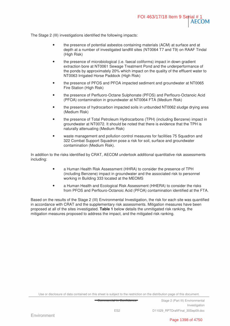
Use or disclosure of data contained on this sheet is subject to the restriction on the distribution page of this document.
Commercial in Confidence Stage 2 (Part III) Environmental
Investigation
ES2 D11029_RPTDraftFinal_30Sep09.doc
The Stage 2 (III) investigations identified the following impacts:
• the presence of potential asbestos containing materials (ACM) at surface and at depth at a number of investigated landfill sites (NT0064 T7 and T9) on RAAF Tindal (High Risk)
• the presence of microbiological (i.e. faecal coliforms) impact in down gradient extraction bore at NT0061 Sewage Treatment Pond and the underperformance of the ponds by approximately 20% which impact on the quality of the effluent water to NT0063 Irrigated Horse Paddock (High Risk)
• the presence of PFOS and PFOA impacted sediment and groundwater at NT0065 Fire Station (High Risk)
• the presence of Perfluoro-Octane Sulphonate (PFOS) and Perflouro-Octanoic Acid (PFOA) contamination in groundwater at NT0064 FTA (Medium Risk)
• the presence of hydrocarbon impacted soils in unbunded NT0062 sludge drying area (Medium Risk)
• the presence of Total Petroleum Hydrocarbons (TPH) (including Benzene) impact in groundwater at NT0072. It should be noted that there is evidence that the TPH is naturally attenuating (Medium Risk)
• waste management and pollution control measures for facilities 75 Squadron and 322 Combat Support Squadron pose a risk for soil, surface and groundwater contamination (Medium Risk).
In addition to the risks identified by CRAT, AECOM undertook additional quantitative risk assessments including:
• a Human Health Risk Assessment (HHRA) to consider the presence of TPH (including Benzene) impact in groundwater and the associated risk to personnel working in Building 333 located at the MEOMS
• a Human Health and Ecological Risk Assessment (HHERA) to consider the risks from PFOS and Perflouro-Octanoic Acid (PFOA) contamination identified at the FTA.
Based on the results of the Stage 2 (III) Environmental Investigation, the risk for each site was quantified in accordance with CRAT and the supplementary risk assessments. Mitigation measures have been proposed at all of the sites investigated. Table 1 below details the unmitigated risk ranking, the mitigation measures proposed to address the impact, and the mitigated risk ranking.
FOI 463/17/18 Item 9 Serial # 1
Page 1398 of 4750
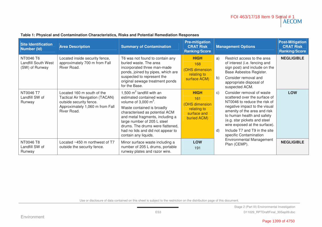
Use or disclosure of data contained on this sheet is subject to the restriction on the distribution page of this document.
Stage 2 (Part III) Environmental Investigation
ES3 D11029_RPTDraftFinal_30Sep09.doc
Table 1: Physical and Contamination Characteristics, Risks and Potential Remediation Responses
Site Identification Number (Id)
Area Description Summary of Contamination Pre-mitigation
CRAT Risk Ranking/Score
Management Options Post-Mitigation
CRAT Risk Ranking/Score
NT0046 T6 Landfill South West (SW) of Runway
Located inside security fence, approximately 700 m from Fall River Road.
T6 was not found to contain any buried waste. The area incorporated three man-made ponds, joined by pipes, which are suspected to represent the original sewage treatment ponds for the Base.
HIGH
168
(OHS dimension relating to
surface ACM)
NEGLIGIBLE
NT0046 T7 Landfill SW of Runway
Located 160 m south of the Tactical Air Navigation (TACAN) outside security fence. Approximately 1,060 m from Fall River Road.
1,500 m2 landfill with an estimated contained waste volume of 3,000 m3.
Waste contained is broadly characterised as potential ACM and metal fragments, including a large number of 205 L steel drums. The drums were flattened, had no lids and did not appear to contain any liquids.
HIGH
161
(OHS dimension relating to
surface and buried ACM)
LOW
NT0046 T8 Landfill SW of Runway
Located ~450 m northwest of T7 outside the security fence.
Minor surface waste including a number of 205 L drums, portable runway plates and razor wire.
LOW
191
a) Restrict access to the area of interest (i.e. fencing and sign post) and include on the Base Asbestos Register.
b) Consider removal and appropriate disposal of suspected ACM.
c) Consider removal of waste scattered over the surface of NT0046 to reduce the risk of negative impact to the visual amenity of the area and risk to human health and safety (e.g. star pickets and steel wire exposed at the surface).
d) Include T7 and T9 in the site specific Contamination Environmental Management Plan (CEMP). NEGLIGIBLE
FOI 463/17/18 Item 9 Serial # 1
Page 1399 of 4750
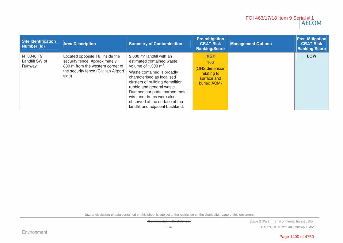
Use or disclosure of data contained on this sheet is subject to the restriction on the distribution page of this document.
Commercial in Confidence Stage 2 (Part III) Environmental Investigation
ES4 D11029_RPTDraftFinal_30Sep09.doc
Site Identification Number (Id)
Area Description Summary of Contamination Pre-mitigation
CRAT Risk Ranking/Score
Management Options Post-Mitigation
CRAT Risk Ranking/Score
NT0046 T9 Landfill SW of Runway
Located opposite T8, inside the security fence. Approximately 830 m from the western corner of the security fence (Civilian Airport side).
2,600 m2 landfill with an estimated contained waste volume of 1,300 m3.
Waste contained is broadly characterised as localised clusters of building demolition rubble and general waste. Dumped car parts, barbed metal wire and drums were also observed at the surface of the landfill and adjacent bushland.
HIGH
166
(OHS dimension relating to
surface and buried ACM)
LOW
FOI 463/17/18 Item 9 Serial # 1
Page 1400 of 4750

Use or disclosure of data contained on this sheet is subject to the restriction on the distribution page of this document.
Commercial in Confidence Stage 2 (Part III) Environmental Investigation
ES5 D11029_RPTDraftFinal_30Sep09.doc
Site Identification Number (Id)
Area Description Summary of Contamination Pre-mitigation
CRAT Risk Ranking/Score
Management Options Post-Mitigation
CRAT Risk Ranking/Score
NT0048 Waste disposal near old hangar area (also referred to as Landfill T3)
Approximately 20-years ago the site was reported to be used for a waste disposal area near the old Hangar buildings on the south-western side of Tarkan Road. The waste disposed at the site included domestic waste, green waste, general building material, scrap steel waste and tyres. It was also reported that approximately 50 x 205 L drums were buried in the area containing Toluene Di-Isocyanide (TDI).
Chemical contamination was not identified in soil or groundwater in concentrations that exceeded the NEPM HILF for industrial/commercial land use and Australian and New Zealand Environment and Conservation Council (ANZECC) 95% protection trigger values. No buried waste, explosive residues or evidence of UXOs were detected during the intrusive investigation. Historical underground service pipes may contain ACM.
There is a potential occupational health and safety issue for Defence personnel and contractors being exposed to the numerous open concrete pits (possible septic or waste water tanks) located across the site.
HIGH
178
(OHS dimension based on buried
ACM)
a) Consider removal and/or filling in of the concrete pits located on the north western side of the site given that they may pose a risk to human health and safety.
b) Include NT0048 in the site specific CEMP, highlighting the risk of encountering ACM associated with the old underground services located across the area.
NEGLIGIBLE
FOI 463/17/18 Item 9 Serial # 1
Page 1401 of 4750

Use or disclosure of data contained on this sheet is subject to the restriction on the distribution page of this document.
Commercial in Confidence Stage 2 (Part III) Environmental Investigation
ES6 D11029_RPTDraftFinal_30Sep09.doc
Site Identification Number (Id)
Area Description Summary of Contamination Pre-mitigation
CRAT Risk Ranking/Score
Management Options Post-Mitigation
CRAT Risk Ranking/Score
NT0049 Disposal near Search and Rescue (SAR) (also referred to as Landfill T4)
Located adjacent to the SAR Hangar, ~ 10 m east. The disposal area was reported to comprise of a former living quarters (remnant concrete foundations (including septics, asbestos and steel) and the burial area. The area investigated was oval in shape and approximately 50 m long x 40 m wide (0.2 ha).
Chemical contamination was not identified in soil or groundwater that exceeded the NEPM HILF for industrial/commercial land use and the ANZECC 95% protection trigger values. No explosive residues, evidence of unexploded ordnances (UXO), asbestos, or buried waste were detected during the intrusive investigation.
Potential ACM was observed on the ground surface of the area of interest and surrounds creating a potential risk of exposure of contractors to ACM if conducting intrusive and/or maintenance activities.
HIGH
186
(OHS dimension based on buried
ACM (i.e. underground
services which may be ACM)
a) Consider removal and appropriate disposal of suspected ACM (i.e. emu parade)
b) Consider the removal of waste (i.e. drums, portable runways etc.) scattered over the surface of NT0049 to reduce the risk of negative impact to the visual amenity of the area and risk to human health and safety (e.g. star pickets, razor wire etc. at the surface).
NEGLIGIBLE
NT0050 Waste disposal near ordnance preparation area
Located southern side of Cape Gloucester Road, approximately 110 m from ordnance preparation area fence.
Reported waste materials disposed of at the site included building rubble and concrete across an area of approximately 60 m x 30 m.
Chemical contamination was not identified in soil or groundwater that exceeded the NEPM HILF for industrial/commercial land use and the ANZECC 95% protection trigger values. No explosive residues, evidence of UXO, asbestos or evidence of ACM were detected during the intrusive investigation.
LOW
198
a) Include NT0050 on the site specific Contamination Environmental Management Plan, highlighting location of the inert landfill materials.
LOW
FOI 463/17/18 Item 9 Serial # 1
Page 1402 of 4750
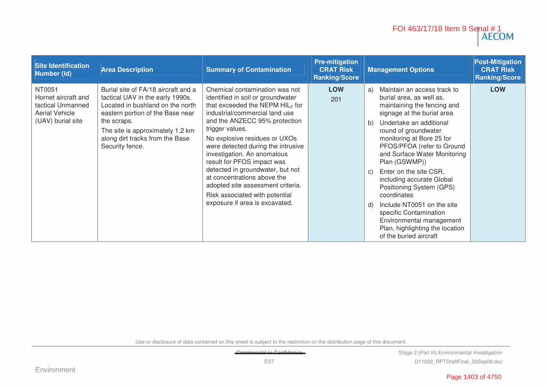
Use or disclosure of data contained on this sheet is subject to the restriction on the distribution page of this document.
Commercial in Confidence Stage 2 (Part III) Environmental Investigation
ES7 D11029_RPTDraftFinal_30Sep09.doc
Site Identification Number (Id)
Area Description Summary of Contamination Pre-mitigation
CRAT Risk Ranking/Score
Management Options Post-Mitigation
CRAT Risk Ranking/Score
NT0051 Hornet aircraft and tactical Unmanned Aerial Vehicle (UAV) burial site
Burial site of FA/18 aircraft and a tactical UAV in the early 1990s. Located in bushland on the north eastern portion of the Base near the scraps.
The site is approximately 1.2 km along dirt tracks from the Base Security fence.
Chemical contamination was not identified in soil or groundwater that exceeded the NEPM HILF for industrial/commercial land use and the ANZECC 95% protection trigger values.
No explosive residues or UXOs were detected during the intrusive investigation. An anomalous result for PFOS impact was detected in groundwater, but not at concentrations above the adopted site assessment criteria.
Risk associated with potential exposure if area is excavated.
LOW
201
a) Maintain an access track to burial area, as well as, maintaining the fencing and signage at the burial area
b) Undertake an additional round of groundwater monitoring at Bore 25 for PFOS/PFOA (refer to Ground and Surface Water Monitoring Plan (GSWMP))
c) Enter on the site CSR, including accurate Global Positioning System (GPS) coordinates
d) Include NT0051 on the site specific Contamination Environmental management Plan, highlighting the location of the buried aircraft
LOW
FOI 463/17/18 Item 9 Serial # 1
Page 1403 of 4750
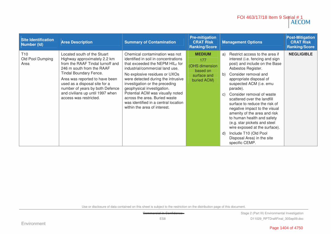
Use or disclosure of data contained on this sheet is subject to the restriction on the distribution page of this document.
Commercial in Confidence Stage 2 (Part III) Environmental Investigation
ES8 D11029_RPTDraftFinal_30Sep09.doc
Site Identification Number (Id)
Area Description Summary of Contamination Pre-mitigation
CRAT Risk Ranking/Score
Management Options Post-Mitigation
CRAT Risk Ranking/Score
T10 Old Pool Dumping Area
Located south of the Stuart Highway approximately 2.2 km from the RAAF Tindal turnoff and 246 m south from the RAAF Tindal Boundary Fence.
Area was reported to have been used as a disposal site for a number of years by both Defence and civilians up until 1997 when access was restricted.
Chemical contamination was not identified in soil in concentrations that exceeded the NEPM HILF for industrial/commercial land use.
No explosive residues or UXOs were detected during the intrusive investigation or the preceding geophysical investigation. Potential ACM was visually noted across the area. Buried waste was identified in a central location within the area of interest.
MEDIUM
177
(OHS dimension based on
surface and buried ACM)
a) Restrict access to the area if interest (i.e. fencing and sign post) and include on the Base Asbestos Register.
b) Consider removal and appropriate disposal of suspected ACM (i.e. emu parade).
c) Consider removal of waste scattered over the landfill surface to reduce the risk of negative impact to the visual amenity of the area and risk to human health and safety (e.g. star pickets and steel wire exposed at the surface).
d) Include T10 (Old Pool Disposal Area) in the site specific CEMP.
NEGLIGIBLE
FOI 463/17/18 Item 9 Serial # 1
Page 1404 of 4750
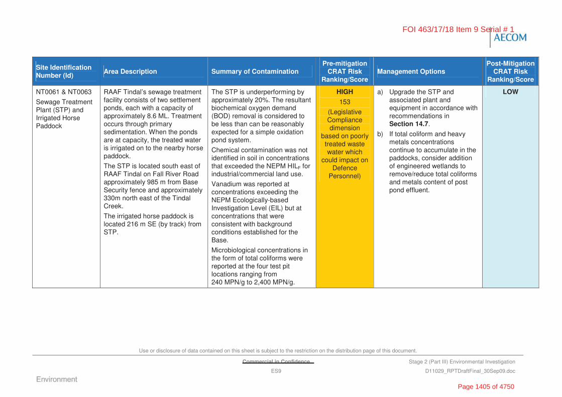
Use or disclosure of data contained on this sheet is subject to the restriction on the distribution page of this document.
Commercial in Confidence Stage 2 (Part III) Environmental Investigation
ES9 D11029_RPTDraftFinal_30Sep09.doc
Site Identification Number (Id)
Area Description Summary of Contamination Pre-mitigation
CRAT Risk Ranking/Score
Management Options Post-Mitigation
CRAT Risk Ranking/Score
NT0061 & NT0063
Sewage Treatment Plant (STP) and Irrigated Horse Paddock
RAAF Tindal’s sewage treatment facility consists of two settlement ponds, each with a capacity of approximately 8.6 ML. Treatment occurs through primary sedimentation. When the ponds are at capacity, the treated water is irrigated on to the nearby horse paddock.
The STP is located south east of RAAF Tindal on Fall River Road approximately 985 m from Base Security fence and approximately 330m north east of the Tindal Creek.
The irrigated horse paddock is located 216 m SE (by track) from STP.
The STP is underperforming by approximately 20%. The resultant biochemical oxygen demand (BOD) removal is considered to be less than can be reasonably expected for a simple oxidation pond system.
Chemical contamination was not identified in soil in concentrations that exceeded the NEPM HILF for industrial/commercial land use.
Vanadium was reported at concentrations exceeding the NEPM Ecologically-based Investigation Level (EIL) but at concentrations that were consistent with background conditions established for the Base.
Microbiological concentrations in the form of total coliforms were reported at the four test pit locations ranging from 240 MPN/g to 2,400 MPN/g.
HIGH
153
(Legislative Compliance dimension
based on poorly treated waste water which
could impact on Defence
Personnel)
a) Upgrade the STP and associated plant and equipment in accordance with recommendations in Section 14.7.
b) If total coliform and heavy metals concentrations continue to accumulate in the paddocks, consider addition of engineered wetlands to remove/reduce total coliforms and metals content of post pond effluent.
LOW
FOI 463/17/18 Item 9 Serial # 1
Page 1405 of 4750
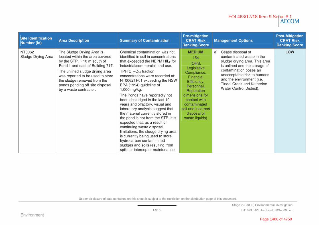
Use or disclosure of data contained on this sheet is subject to the restriction on the distribution page of this document.
Stage 2 (Part III) Environmental Investigation
ES10 D11029_RPTDraftFinal_30Sep09.doc
Site Identification Number (Id)
Area Description Summary of Contamination Pre-mitigation
CRAT Risk Ranking/Score
Management Options Post-Mitigation
CRAT Risk Ranking/Score
NT0062 Sludge Drying Area
The Sludge Drying Area is located within the area covered by the STP, ~ 10 m south of Pond 1 and east of Building 717.
The unlined sludge drying area was reported to be used to store the sludge removed from the ponds pending off-site disposal by a waste contractor.
Chemical contamination was not identified in soil in concentrations that exceeded the NEPM HILF for industrial/commercial land use.
TPH C10-C36 fraction concentrations were recorded at: NT0062TP01 exceeding the NSW EPA (1994) guideline of 1,000 mg/kg.
The Ponds have reportedly not been desludged in the last 10 years and olfactory, visual and laboratory analysis suggest that the material currently stored in the pond is not from the STP. It is expected that, as a result of continuing waste disposal limitations, the sludge drying area is currently being used to store hydrocarbon contaminated sludges and soils resulting from spills or interceptor maintenance.
MEDIUM
154
(OHS, Legislative
Compliance, Financial Efficiency, Personnel, Reputation
dimensions for contact with
contaminated soil and incorrect
disposal of waste liquids)
a) Cease disposal of contaminated waste in the sludge drying area. This area is unlined and the storage of contamination poses an unacceptable risk to humans and the environment (i.e. Tindal Creek and Katherine Water Control District).
LOW
FOI 463/17/18 Item 9 Serial # 1
Page 1406 of 4750

Use or disclosure of data contained on this sheet is subject to the restriction on the distribution page of this document.
Stage 2 (Part III) Environmental Investigation
ES11 D11029_RPTDraftFinal_30Sep09.doc
Site Identification Number (Id)
Area Description Summary of Contamination Pre-mitigation
CRAT Risk Ranking/Score
Management Options Post-Mitigation
CRAT Risk Ranking/Score
NT0064 Fire Training Area
Located south of RAAF Tindal security fence on Fall River Road approximately 188 m from the Base security fence and approximately 800 m north of Tindal Creek. The FTA incorporates a lined fire pit, 3 x evaporation ponds, cleared area and practice equipment. Previous and current investigation identified concentrations of PFOS in soil and groundwater.
Perfluoro-octansulfonate (PFOS) was confirmed in groundwater at concentrations exceeding the Minnesota Department of Health (MDH) guideline value for potable water. PFOS concentrations reported were consistent with those identified by previous investigations (ERM, 2007a; GHD, 2008).
Heavy metals concentrations were reported in the groundwater exceeding the ANZECC 95% protection trigger values and were also consistent.
PFOS contamination in soil has been reported by previous investigations (ERM, 2007a and GHD, 2008) at concentrations which exceed the MDH guideline for commercial/industrial land use.
The HHSERA identified that the current concentrations in the soil and groundwater do not represent an unacceptable risk to onsite personnel; however, onsite ecological receptors may be impacted.
MEDIUM
143
(OHS dimension based on inhalation,
ingestion or dermal contact
with contaminated
soil and/or groundwater)
a) Ongoing monitoring of the groundwater at the FTA, including 064MW07 located near Tindal Creek for PFOS/PFOA concentrations (refer to GSWMP).
b) Include the FTA on the site specific Contamination Environmental Management Plan pending implementation of the recommendations in the RAP.
MEDIUM
FOI 463/17/18 Item 9 Serial # 1
Page 1407 of 4750
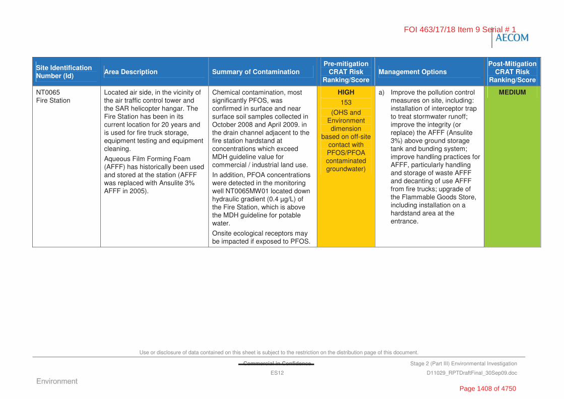
Use or disclosure of data contained on this sheet is subject to the restriction on the distribution page of this document.
Commercial in Confidence Stage 2 (Part III) Environmental Investigation
ES12 D11029_RPTDraftFinal_30Sep09.doc
Site Identification Number (Id)
Area Description Summary of Contamination Pre-mitigation
CRAT Risk Ranking/Score
Management Options Post-Mitigation
CRAT Risk Ranking/Score
NT0065 Fire Station
Located air side, in the vicinity of the air traffic control tower and the SAR helicopter hangar. The Fire Station has been in its current location for 20 years and is used for fire truck storage, equipment testing and equipment cleaning.
Aqueous Film Forming Foam (AFFF) has historically been used and stored at the station (AFFF was replaced with Ansulite 3% AFFF in 2005).
Chemical contamination, most significantly PFOS, was confirmed in surface and near surface soil samples collected in October 2008 and April 2009. in the drain channel adjacent to the fire station hardstand at concentrations which exceed MDH guideline value for commercial / industrial land use.
In addition, PFOA concentrations were detected in the monitoring well NT0065MW01 located down hydraulic gradient (0.4 μg/L) of the Fire Station, which is above the MDH guideline for potable water.
Onsite ecological receptors may be impacted if exposed to PFOS.
HIGH
153
(OHS and Environment dimension
based on off-site contact with PFOS/PFOA contaminated groundwater)
a) Improve the pollution control measures on site, including: installation of interceptor trap to treat stormwater runoff; improve the integrity (or replace) the AFFF (Ansulite 3%) above ground storage tank and bunding system; improve handling practices for AFFF, particularly handling and storage of waste AFFF and decanting of use AFFF from fire trucks; upgrade of the Flammable Goods Store, including installation on a hardstand area at the entrance.
MEDIUM
FOI 463/17/18 Item 9 Serial # 1
Page 1408 of 4750
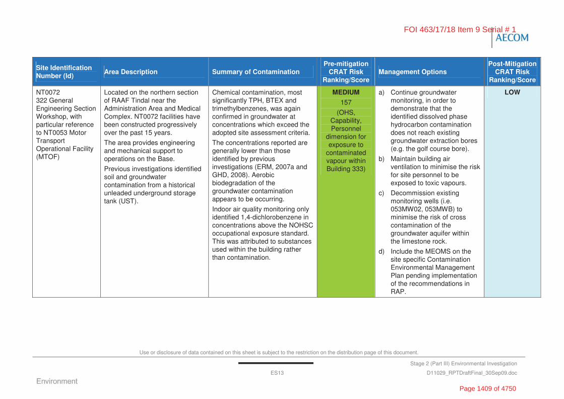
Use or disclosure of data contained on this sheet is subject to the restriction on the distribution page of this document.
Stage 2 (Part III) Environmental Investigation
ES13 D11029_RPTDraftFinal_30Sep09.doc
Site Identification Number (Id)
Area Description Summary of Contamination Pre-mitigation
CRAT Risk Ranking/Score
Management Options Post-Mitigation
CRAT Risk Ranking/Score
NT0072 322 General Engineering Section Workshop, with particular reference to NT0053 Motor Transport Operational Facility (MTOF)
Located on the northern section of RAAF Tindal near the Administration Area and Medical Complex. NT0072 facilities have been constructed progressively over the past 15 years.
The area provides engineering and mechanical support to operations on the Base.
Previous investigations identified soil and groundwater contamination from a historical unleaded underground storage tank (UST).
Chemical contamination, most significantly TPH, BTEX and trimethylbenzenes, was again confirmed in groundwater at concentrations which exceed the adopted site assessment criteria.
The concentrations reported are generally lower than those identified by previous investigations (ERM, 2007a and GHD, 2008). Aerobic biodegradation of the groundwater contamination appears to be occurring.
Indoor air quality monitoring only identified 1,4-dichlorobenzene in concentrations above the NOHSC occupational exposure standard. This was attributed to substances used within the building rather than contamination.
MEDIUM
157
(OHS, Capability, Personnel
dimension for exposure to
contaminated vapour within Building 333)
a) Continue groundwater monitoring, in order to demonstrate that the identified dissolved phase hydrocarbon contamination does not reach existing groundwater extraction bores (e.g. the golf course bore).
b) Maintain building air ventilation to minimise the risk for site personnel to be exposed to toxic vapours.
c) Decommission existing monitoring wells (i.e. 053MW02, 053MWB) to minimise the risk of cross contamination of the groundwater aquifer within the limestone rock.
d) Include the MEOMS on the site specific Contamination Environmental Management Plan pending implementation of the recommendations in RAP.
LOW
FOI 463/17/18 Item 9 Serial # 1
Page 1409 of 4750
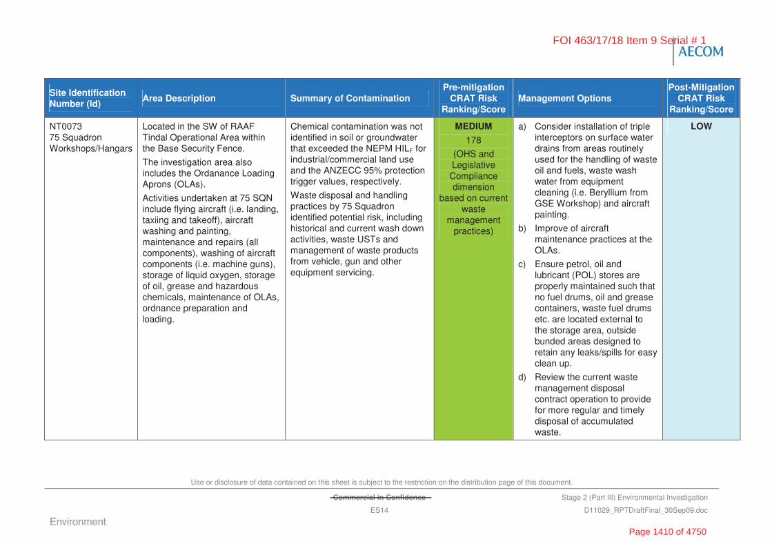
Use or disclosure of data contained on this sheet is subject to the restriction on the distribution page of this document.
Commercial in Confidence Stage 2 (Part III) Environmental Investigation
ES14 D11029_RPTDraftFinal_30Sep09.doc
Site Identification Number (Id)
Area Description Summary of Contamination Pre-mitigation
CRAT Risk Ranking/Score
Management Options Post-Mitigation
CRAT Risk Ranking/Score
NT0073 75 Squadron Workshops/Hangars
Located in the SW of RAAF Tindal Operational Area within the Base Security Fence.
The investigation area also includes the Ordanance Loading Aprons (OLAs).
Activities undertaken at 75 SQN include flying aircraft (i.e. landing, taxiing and takeoff), aircraft washing and painting, maintenance and repairs (all components), washing of aircraft components (i.e. machine guns), storage of liquid oxygen, storage of oil, grease and hazardous chemicals, maintenance of OLAs, ordnance preparation and loading.
Chemical contamination was not identified in soil or groundwater that exceeded the NEPM HILF for industrial/commercial land use and the ANZECC 95% protection trigger values, respectively.
Waste disposal and handling practices by 75 Squadron identified potential risk, including historical and current wash down activities, waste USTs and management of waste products from vehicle, gun and other equipment servicing.
MEDIUM
178
(OHS and Legislative Compliance dimension
based on current waste
management practices)
a) Consider installation of triple interceptors on surface water drains from areas routinely used for the handling of waste oil and fuels, waste wash water from equipment cleaning (i.e. Beryllium from GSE Workshop) and aircraft painting.
b) Improve of aircraft maintenance practices at the OLAs.
c) Ensure petrol, oil and lubricant (POL) stores are properly maintained such that no fuel drums, oil and grease containers, waste fuel drums etc. are located external to the storage area, outside bunded areas designed to retain any leaks/spills for easy clean up.
d) Review the current waste management disposal contract operation to provide for more regular and timely disposal of accumulated waste.
LOW
FOI 463/17/18 Item 9 Serial # 1
Page 1410 of 4750

Use or disclosure of data contained on this sheet is subject to the restriction on the distribution page of this document.
Stage 2 (Part III) Environmental
Investigation
ES15 D11029_RPTDraftFinal_30Sep09.doc
INSERT FIGURE WITH INVESTIGATION AREAS
FOI 463/17/18 Item 9 Serial # 1
Page 1411 of 4750

Use or disclosure of data contained on this sheet is subject to the restriction on the distribution page of this document.
Stage 2 (Part III) Environmental
Investigation
ES16 D11029_RPTDraftFinal_30Sep09.doc
“This page has been left blank intentionally”
FOI 463/17/18 Item 9 Serial # 1
Page 1412 of 4750
Use or disclosure of data contained on this sheet is subject to the restriction on the distribution page of this document.
Commercial in Confidence Stage 2 (Part III) Environmental
Investigation
1 D11029_RPTDraftFinal_30Sep09.doc
1.0 Introduction and Background
1.1 Introduction
ENSR Australia Pty Ltd (trading as AECOM and hereafter referred to as AECOM) was commissioned by the Department of Defence (Defence) to undertake a Stage 2 (Part III) Environmental Investigation (Stage 2 (III) Investigation) within the designated areas of interest at RAAF Base Tindal (RAAF Tindal, the Base), Katherine, Northern Territory (Figure F1).
Historical operations and past practices at the Base have resulted in a number of areas that may or are known to be potentially contaminated. As described by Section 1.6 and Section 3.8, several of these areas of interest have been the subject of previous Stage 1 and Stage 2 Environmental Investigations and monitoring programs. This Stage 2 (III) Investigation was designed to draw from and build on the information obtained from the preceding investigation programs. Areas of interest considered by the Stage 2 (III) investigation included:
• historical landfills and burial sites (CSR Reference: NT0046 (T6, T7, T8 and T9), T10, NT0048, NT0049, NT0050 and NT0051)
• the Sewage Treatment Facilities including the STP, irrigated horse paddock and sludge drying area (CSR Reference: NT0061, NT0062 and NT0063)
• the FTA and Fire Station (CSR Reference: NT0064 and NT0065)
• Building 333 at MEOMS (CSR Reference: NT0053) which forms part of the larger 322 General Engineering Section (322 GSS) Workshops (CSR Reference: NT0072)
• facilities at 75 SQN (CSR Reference: NT0073)
• the integrity of 21 underground storage tanks (USTs) located across the Base.
Further investigation of these areas was considered appropriate to confirm and refine the potential human health and ecological risks highlighted by previous investigations and to identify appropriate management strategies for future development and implementation. The location of the sites investigated is shown in Figure F2.
The work was commissioned by Melissa Woltmann of Defence on 6 September 2008. Revisions to the project scope were made progressively during the fieldwork program in consultation with Defence and its Technical Advisor (TA), The revisions included changes to the required scope of work in response to observations made during the field investigation program, in particular:
• inclusion of indoor vapour monitoring within Building 333 (NT0072)
• the installation of two additional monitoring wells at the 75 Squadron (NT0073)
• the inclusion of the old pool dumping site located on the northern boundary (T10)
• the pump out of waste water from underground storage tanks that were to be subject to integrity testing
• the inclusion of a Human Health and Ecological Risk Assessment of the FTA (NT0064).
These revisions were formally approved by Melissa Woltmann via e-mails between 10 October 2008 and 1 December 2008.
FOI 463/17/18 Item 9 Serial # 1
s47G
Page 1413 of 4750
Use or disclosure of data contained on this sheet is subject to the restriction on the distribution page of this document.
Stage 2 (Part III) Environmental
Investigation
2 D11029_RPTDraftFinal_30Sep09.doc
1.2 Site Description
RAAF Tindal covers an area of approximately 122 square kilometres (km2) and is located within the Northern Territory; 330 km south east of Darwin and 14 km south east of Katherine. The current Base was opened in 1988 and plays an important role for Defence as the only operational, tactical fighter Base in the Northern Territory. RAAF Tindal is a joint civil-military airfield, with taxiways and a runway shared by the Royal Australian Air Force (RAAF)
important medical services such as Air Medivac and the Katherine Town Council managed civilian airport, Katherine Airport.
A brief summary of the Base history is as follows:
1942-1944 A small airfield/base was established by an element of the American Engineer Regiment during WWII and completed in 1944 by an element of the Victorian Country Roads Board.
1950-1960 The Base was reconstructed and extended by RAAF’s No. 5 Airfield Squadron to provide a backup airfield for Darwin.
1963-1970 The Base was upgraded for use as an airfield for exercises and civilian use and as a ‘bare base’.
1980-1987 Further significant upgrade and expansion of the facilities were undertaken, which has resulted in the Base as it is known today.
1988 RAAF Base Tindal was established and operational after the Australian Government decided to move the RAAF’s Tactical Fighter Force, consisting of 75 Squadron (75 Sqn) and 322 Combat Support Wing (322 CSW), from Darwin to Tindal.
A more detailed description of the Base is provided in Section 3.0.
1.3 Objectives
In complying with the requirements of the Environment Protection and Biodiversity Conservation Act 1999 (EPBC Act), the Department of Defence is obligated to ensure that the biological, social and cultural environment in which it operates are not adversely affected, onsite or offsite, as a result of Defence activities. As such, Defence undertake investigations, monitoring and management programs to minimise their impact to their surrounding environment.
The ultimate objective for the Stage 2 (III) Environmental Investigation was to understand the true risks associated with potential contamination at the site and make specific National Environmental Protection (Assessment of Site Contamination) Measures 1999 (NEPM) compliant management and remediation recommendations to reduce the risk to Defence.
Within the context of this objective, the specific aims of the Stage 2 (III) Investigations are to draw from and build on the information and recommendations from previous investigations undertaken at RAAF Tindal in order to:
• assess the nature and extent of contamination at each of the CSR sites identified in the Statement of Requirement (SOR)
• assess the risk score and ranking using the CRAT
• assess the whole of Base risk to Defence associated with the identified contamination
FOI 463/17/18 Item 9 Serial # 1
s33s33
Page 1414 of 4750
Use or disclosure of data contained on this sheet is subject to the restriction on the distribution page of this document.
Stage 2 (Part III) Environmental
Investigation
3 D11029_RPTDraftFinal_30Sep09.doc
• provide pragmatic, specific management and remediation recommendations, compliant with NEPM 1999, that are cognisant of the remote location and logistical constraints at RAAF Tindal, and that will address the risks at each of the areas of interest and at RAAF Tindal as a whole.
It should be noted that this project has been completed as a snap shot in time on the environmental conditions of the site. Such conditions may change over time.
1.4 Scope of Work
1.4.1 Stage 2 (III) Environmental Investigation
The 16 areas of interest investigated during the Stage 2 (III) Investigation were based on the SOR (Defence, 2008), AECOM’s proposal dated 6 August 2008 (Ref: D1102990_PRPFinal_PartA_06Aug08) and the outcome of site inspections and stakeholder discussions during the initial stages of the project. The areas of interest were all located within the Commonwealth Property Boundary of RAAF Tindal (Figure F2).
This report describes the conduct and the findings of the Stage 2 (III) field investigations undertaken by AECOM during October and November 2008. In particular, the Stage 2 (III) investigation included:
• review of the available data for the Base including a summary of relevant information from the previous Stage 1 and 2 investigation reports (refer to Section 1.6)
• review of previous investigation and historical well logs and groundwater quality data available for the areas of interest
• design and preparation of a Sampling and Analysis Plan (SAP) after the inception meeting site inspection including:
- consideration of a Conceptual Site Model
- development of the site investigation using a range of environmental investigation methods to evaluate the presence and extent of contamination
- development of data quality objectives
• collection of soil, sediment, surface water and groundwater samples to assess the nature and extent of contamination including sampling to assist in the evaluation of the lateral and vertical extent of the impact
• assessment of risks associated with the contamination using the Defence CRAT (Version 2, 16 February 2007) developed for assessing the risks with Defence contaminated sites
• reporting of results (this report).
AECOM mainta on with Defence representatives and stakeholders, as well as Defence’s TA, throughout the project. The proposed work methodology and progress updates were detailed in:
• the project start up meeting
• minutes of discussions between AECOM and the Defence Project Manager, TA and other Defence stakeholders (as appropriate).
FOI 463/17/18 Item 9 Serial # 1
s47G
Page 1415 of 4750

Use or disclosure of data contained on this sheet is subject to the restriction on the distribution page of this document.
Commercial in Confidence Stage 2 (Part III) Environmental
Investigation
4 D11029_RPTDraftFinal_30Sep09.doc
In addition, the TA conducted a site visit during the intrusive fieldwork program during which modifications to the required scope of work were agreed, in consultation with Defence, between AECOM’s fieldwork coordinator and the TA, based on the observed site conditions. The dynamic nature of the fieldwork program and the progressive refinement of the scope of work in response to the observed field conditions reflected Defence’s requirement to accomplish the project objectives with a single site mobilisation.
The desktop and field based information obtained throughout the investigation are considered to provide adequate temporal data to allow for AECOM to assess the nature and extent of contamination at each of the areas of interest.
1.4.2 Other Related Activities
In addition to the Stage 2 (III) Environmental Investigation, AECOM was also engaged to deliver the following related activities:
1 review of existing ground and surface water monitoring practices at the Base and update of such in the form of a revised, consolidated Ground and Surface Water Monitoring Plan (GSWMP)
2 development of a Contamination Environmental Management Plan (CEMP), which summarises contamination identified by the Stage 2 (III) Investigation and describes management controls that must be implemented when working within these areas
3 preparation of a Remedial Action Plan (RAP) which:
a) considers management and remediation options for areas of interest in which contamination is found, by the Stage 2 (III) Investigation, to represent an unacceptable risk to Defence
b) recommends a preferred management or remediation strategy for effectively mitigating the identified risks.
The outcome of these related activities have been reported separately.
1.5 Guidelines and Legislation
The Stage 2 (III) Investigation has been designed to generally follow the guidance from relevant aspects of the National Environmental Protection (Assessment of Site Contamination) Measure (NEPM), published by the National Environment Protection Council (NEPC, 1999). The program has also considered the Defence Contamination Management Strategy, the Defence Contamination Management Manual and Australian Standard AS4482.1 2005.
1.5.1 NEPM
The NEPM (1999) has been adopted by the various states and territories of Australia, including NT. The NEPM incorporates a recommended general process for the assessment of site contamination, and a set of 10 specific guidelines. The process and guidelines are closely based on existing documentation already widely used for assessing site contamination (such as ANZECC/NHRMC 1992, ANZECC 1992 and the various National Environmental Health Forum monographs and proceedings). The 10 specific guidelines incorporated into the NEPM include:
• Schedule B(1) Guideline on Investigation Levels for Soil and Groundwater
• Schedule B(2) Guideline on Data Collection, Sample Design and Reporting of Data
• Schedule B(3) Guideline on Laboratory Analysis of Potentially Contaminated Soils
FOI 463/17/18 Item 9 Serial # 1
Page 1416 of 4750

Use or disclosure of data contained on this sheet is subject to the restriction on the distribution page of this document.
Stage 2 (Part III) Environmental
Investigation
5 D11029_RPTDraftFinal_30Sep09.doc
• Schedule B(4) Guideline on Health Risk Assessment Methodology
• Schedule B(5) Guideline on Ecological Risk Assessment
• Schedule B(6) Guideline on Assessment of Groundwater Contamination
• Schedule B(7a) Guideline on Health–based Investigation Levels
• Schedule B(7b) Guideline on Exposure Scenarios and Exposure Settings
• Schedule B(8) Guideline on Community Consultation and Risk Communication
• Schedule B(9) Guideline on Protection of Health & the Environment during the Assessment of Contaminated Sites
• Schedule B(10) Guideline on Competencies & Acceptance of Contaminated Land Auditors and Related Professionals.
In particular, the soil investigation process has been designed with reference to NEPM Schedule A: Recommended General Process for Assessment of Site Contamination and NEPM Figure 3-1 Assessment Process for Groundwater Contamination.
The NEPM includes a range of Soil Investigation Levels (SILs) including an interim urban Ecological Investigation Levels (EILs), largely similar to the Environmental Investigation Thresholds (EITs) listed in the Australian and New Zealand Guidelines for The Assessment and Management of Contaminated Sites (ANZECC/National Health and Medical Research Council (NHMRC) (1992)) and Health Investigation Levels (HILs).
1.5.2 National and International Soil Guidelines
The National and International soil guidelines adopted for the Stage 2 (III) Investigations included:
• Guidelines for the Assessment and Management of Contaminated Sites (Australia and New Zealand Environment and Conservation Council/National Health and Medical Research Council (ANZECC/NHMRC), 1992)
• National Environment Protection (Contamination) Measure (1999), Schedule B(2), section 5.2.2 – Guidance on Data Collection, Sample Design and Reporting (NEPC, 1999)
• National Environmental Protection (Assessment of Site Contamination) Manual (NEPC, 1999)
• National Environment Protection (Contamination) Measure Health-based Investigation Levels for Commercial/Industrial Land Use (HILF) (NEPC, 1999)
• National Environment Protection (Contamination) Measure Interim Ecologically-based Investigation Levels (EIL) (NEPC, 1999)
• Guidelines for Assessing Service Station Sites (New South Wales Environmental Protection Agency (NSW EPA), 1994)
• Guidelines for the Assessment, Remediation and Management of Asbestos-Contaminated Sites in Western Australia (Western Australia Department of Health (DOH), 2009)
• Regional Screening Levels (RSLs) for Chemical Contaminants at Superfund Sites (US EPA, 2009)
FOI 463/17/18 Item 9 Serial # 1
Page 1417 of 4750

Use or disclosure of data contained on this sheet is subject to the restriction on the distribution page of this document.
Commercial in Confidence Stage 2 (Part III) Environmental
Investigation
6 D11029_RPTDraftFinal_30Sep09.doc
• Tier 2 Industrial Soil Reference Values for PFOS and PFOA, in Draft Guidelines: Risk-Based Guidance for the Soil-Human Health Pathway (Minnesota Pollution Control Acency (MPCA), 2009)
• Sources and effects of ionising radiation. United Nations Scientific Committee on the Effects of Atomic Radiation, Volume 1: Sources, pp 115-116. Table 5 - Global median value for average natural radionuclides in soil (UNSCEAR, 2000).
1.5.3 National and International Water Guidelines
The National and International water guidelines adopted for the Stage 2 (III) Investigations included:
• Guidelines for Fresh and Marine Water Quality, National Water Quality Management Strategy (ANZECC/NHMRC, 2000)
Note: Given the dynamics and disturbed nature of the receiving waters (i.e. Tindal Creek) the 95% species protection level was adopted, with the exception of compounds that may bioaccumulate where the 99% species protection level was adopted.
• Australian and New Zealand Guidelines for the Assessment and Management of Contaminated Sites (ANZECC/NHMRC, 1992)
• Australian/New Zealand Standard – AS/NZ 5667.11: 1998. Water Quality Sampling Part 11: Guidance on Sampling of Groundwaters
• National Environmental Protection (Assessment of Site Contamination) Manual (NEPC, 1999)
• National Environment Protection (Contamination) Measure (1999), Schedule B(2), section 5.2.2 – Guidance on Data Collection, Sample Design and Reporting (NEPC, 1999)
• Australian Drinking Water Guidelines (NHMRC, 2004) for health and aesthetic based values
• Dutch Intervention Values (Netherlands Ministry of Housing (NMH), 2000) in the absence of TPH criteria within the ANZECC Guidelines
• Chronic Exposure Health Risk Limits for PFOS and PFOA in Drinking Water in Health Risk Limits for Groundwater 2008 Rule Revision for Perfluorooctanoic Acid and Perfluorooctane Sulfonate (Minnesota Department of Health (MDH), 2009)
Note: MDH (2009) provide Health Risk Limits (HRLs) for PFOA and PFOS in groundwater of 0.3 μg/L. The PFOA and PFOS HRLs will be used in the absence of Australasian guidelines for assessment of PFOS and PFOA impacts at RAAF Tindal.
• Provisional Health Advisories for Perfluorooctanoic Acid (PFOA) and Perfluorooctane Sulfonate (PFOS) (US EPA, 2009).
1.5.4 National Sediment Guidelines
The National sediment guidelines adopted for the Stage 2 (III) Investigations included:
• Guidelines for Fresh and Marine Water Quality, National Water Quality Management Strategy (ANZECC/ Agriculture and Resource Management Council of Australia and New Zealand (ARMCANZ), 2000).
FOI 463/17/18 Item 9 Serial # 1
Page 1418 of 4750

Use or disclosure of data contained on this sheet is subject to the restriction on the distribution page of this document.
Commercial in Confidence Stage 2 (Part III) Environmental
Investigation
7 D11029_RPTDraftFinal_30Sep09.doc
1.5.5 Northern Territory Legislation and Guidelines
The Northern Territory legislation and guidelines referred to during the Stage 2 (III) Investigation included:
• Environmental Assessment Act 1982 and Environmental Assessment Amendment Act 1994 – aim to ensure, to the greatest extent practicable, matters affecting the environment are fully examined and taken into account in relation to: development proposals; carrying out of works; and negotiating agreements, decisions and recommendations that may affect the environment. The EPA is responsible for implementation of the Environmental Assessment Act.
• Waste Management and Pollution Control Act 1998 (and as amended in 2003) (WMPC Act) - deals with remediation of contaminated land. A Pollution Abatement Notice can be issued to clean up a contaminated site. Consistent with the polluter pays principle, unless the notice is revoked, the requirements continue to bind the person to whom it was issued where the person sells or ceases to occupy the land. The EPA regulates activities subject to the WMPC Act.
• Water Act 1992 - provides for the investigation, allocation, use, control, protection, management and administration of water resources. The Minister administers the Act through the Controller of Water Resources, while the Controller directs day-to-day operation of the Act and its Regulation within The Department of Natural Resources, Environment, The Arts and Sport (NRETAS). Including the issuing of licences and permits, and intervening in cases of pollution, depletion of water or inequitable distribution.
• Water Allocation Plan for the Tindall Limestone Aquifer, Katherine, 2009-2019 – the aim of the plan is to ensure that the water resource is managed sustainably with a balance between the environment and all other users. The Plan is made under Section 22B of the NT Water Act 1992 and relates to the Katherine Water Control District declared under Section 22 and the Katherine Area Groundwater Beneficial Uses under Section 22A. The objectives of the Plan are to:
- maintain the groundwater contribution to surface waters for the protection of minimum flows in the Katherine River and associated water dependent ecosystems
- ensure the maintenance and protection of values and access to places of importance under traditional laws, customs and practices
- ensure the ongoing maintenance of groundwater quality and quantity from this water source
- to maintain access to this groundwater source for rural stock and domestic purposes
- provide sustainable access to groundwater for urban water supplies
- to provide access to groundwater for agricultural, aquacultural and industrial purposes
- create an effective and enforceable plan that promotes the efficient and equitable use of the water resource.
In August 2009, the Department of Natural Resources, Environment, the Arts and Sport (NRETAS) released the Water Allocation Plan for the Tindall Limestone Aquifer (NRETAS, 2009) to manage the Territory water resources where there is significant competition for water resources from the growing communities, agricultural enterprises and industry users.
FOI 463/17/18 Item 9 Serial # 1
Page 1419 of 4750

Use or disclosure of data contained on this sheet is subject to the restriction on the distribution page of this document.
Commercial in Confidence Stage 2 (Part III) Environmental
Investigation
8 D11029_RPTDraftFinal_30Sep09.doc
The Water Allocation Plan (WAP) provides an objective to preserve a good level of health to the Tindall Limestone Aquifer, one of the Territory’s high yielding, good quality groundwater resource.
The Tindall Limestone Aquifer (Katherine) WAP has been prepared to initiate strategies for sustainably allocating and managing water within the Katherine region.
1.6 Historical Reports
There have been several previous environmental investigations undertaken at RAAF Tindal. Previous investigation reports provided by Defence to AECOM and applicable to the Stage 2 (III) Investigation are summarised in Table 2, below.
Table 2: Applicability of Historical Reports
Author and Date Title Summary
ERM, June 2005 Stage 1 Environmental Investigation, RAAF Base Tindal, Northern Territory
General
Sinclair Knight Mertz (SKM), January 2005
RAAF Tindal EMS Development – Phase 1 Environmental Review Report
General
ERM, June 2007a Stage 1 and 2 Environmental Investigations NT / K, RAAF Base Tindal
ERM 2007a focussed on MEOMS and FTA considered to represent the highest risk to Defence at RAAF Tindal
ERM, June 2007b Landfill/Burial Sites, Stage 1 Environmental Investigations NT/K, RAAF Base Tindal
ERM Stage 1 Report considered all potential areas of interest and identified areas that warranted further consideration
GHD, July 2008 RAAF Base Tindal, Stage 2 (Part II) Environmental Investigation
GHD 2008 focussed on the groundwater contamination elements associated with MEOMS and FTA
SMEC, August 2007 Darwin Bases Water Quality Management Plan
RAAF Tindal (Whole of Base)
HLA-Envirosciences. August 2007
Aboveground & Underground Storage Tank Management Plan - Volume 5 – Northern Territory and Kimberley Region
RAAF Tindal underground storage tanks
A summary of the previous investigations, in relation to each of the CSR sites have been provided in the individual sections of this report (Section 8.0 to Section 18.0). A summary of the underground storage tank integrity testing results is provided in Section 19.0.
1.7 Report Structure
This report is structured as follows:
FOI 463/17/18 Item 9 Serial # 1
Page 1420 of 4750
Use or disclosure of data contained on this sheet is subject to the restriction on the distribution page of this document.
Commercial in Confidence Stage 2 (Part III) Environmental
Investigation
9 D11029_RPTDraftFinal_30Sep09.doc
• Section 1 – details the objectives of the project, the scope of work undertaken, investigation standards and information sources
• Section 2 – provides a general description of investigation approach, with further detail provided in the endorsed Sampling Analysis Plan (Appendix A)
• Section 3 – provides an overview of the sites characteristics including site history, regional and local geology, hydrogeology, hydrology and topography for the site
• Section 4 - provides a conceptual site model, including a list of Chemicals of Potential Concern (CoPC)
• Section 5 - describes the Data Quality Objectives (DQO) adopted for the investigation as well as presenting the results of the fieldwork and laboratory quality control and quality assurance program undertaken during the investigation program
• Section 6 – presents the soil and groundwater criteria used to assess the analytical data
• Section 7 – presents an overview of the Base contamination assessment results
• Section 8 to Section 18 – describes, for each area of interest, the site area, review of previous investigations, history, intrusive investigation program, laboratory results, the risk assessment results and conclusions and recommendations drawn from the investigation program
• Section 19 – presents a summary of the UST integrity testing program findings and recommendations
• Section 20 – presents the conclusions of the Stage 2 (III) investigation program
• Section 21 – presents the limitation of reporting
• Section 22 - lists key references.
Section 1.0 through Section 7.0 provides the background information upon which the subsequent detailed area of interest specific descriptions have been based.
Section 8.0 to Section 19.0 each provide a stand alone discussion of the investigation program undertaken at each area of interest and the identified impact, if any. This approach to reporting is consistent with:
• the Defence CSR and Defence Environmental Management System (EMS), which are based on individual areas of interest
• Defence’s strategy of prioritising the management of individual areas of interest according to risk.
Defence’s risk based strategy may result in the recommended management actions at different areas of interest at a given site being implemented at different times. Providing a stand alone discussion of the identified impact at each area of interest is designed to facilitate this risk based approach.
FOI 463/17/18 Item 9 Serial # 1
Page 1421 of 4750

Use or disclosure of data contained on this sheet is subject to the restriction on the distribution page of this document.
Commercial in Confidence Stage 2 (Part III) Environmental
Investigation
10 D11029_RPTDraftFinal_30Sep09.doc
“This page has been left blank intentionally”
FOI 463/17/18 Item 9 Serial # 1
Page 1422 of 4750
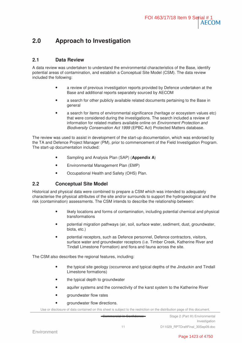
Use or disclosure of data contained on this sheet is subject to the restriction on the distribution page of this document.
Commercial in Confidence Stage 2 (Part III) Environmental
Investigation
11 D11029_RPTDraftFinal_30Sep09.doc
2.0 Approach to Investigation
2.1 Data Review
A data review was undertaken to understand the environmental characteristics of the Base, identify potential areas of contamination, and establish a Conceptual Site Model (CSM). The data review included the following:
• a review of previous investigation reports provided by Defence undertaken at the Base and additional reports separately sourced by AECOM
• a search for other publicly available related documents pertaining to the Base in general
• a search for items of environmental significance (heritage or ecosystem values etc) that were considered during the investigations. The search included a review of information for related matters available online on Environment Protection and Biodiversity Conservation Act 1999 (EPBC Act) Protected Matters database.
The review was used to assist in development of the start-up documentation, which was endorsed by the TA and Defence Project Manager (PM), prior to commencement of the Field Investigation Program. The start-up documentation included:
• Sampling and Analysis Plan (SAP) (Appendix A)
• Environmental Management Plan (EMP)
• Occupational Health and Safety (OHS) Plan.
2.2 Conceptual Site Model
Historical and physical data were combined to prepare a CSM which was intended to adequately characterise the physical attributes of the site and/or surrounds to support the hydrogeological and the risk (contamination) assessments. The CSM intends to describe the relationship between:
• likely locations and forms of contamination, including potential chemical and physical transformations
• potential migration pathways (air, soil, surface water, sediment, dust, groundwater, biota, etc.)
• potential receptors, such as Defence personnel, Defence contractors, visitors, surface water and groundwater receptors (i.e. Timber Creek, Katherine River and Tindall Limestone Formation) and flora and fauna across the site.
The CSM also describes the regional features, including:
• the typical site geology (occurrence and typical depths of the Jinduckin and Tindall Limestone formations)
• the typical depth to groundwater
• aquifer systems and the connectivity of the karst system to the Katherine River
• groundwater flow rates
• groundwater flow directions.
FOI 463/17/18 Item 9 Serial # 1
Page 1423 of 4750
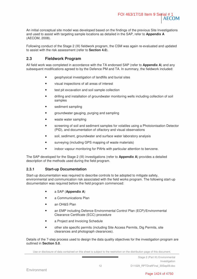
Use or disclosure of data contained on this sheet is subject to the restriction on the distribution page of this document.
Stage 2 (Part III) Environmental
Investigation
12 D11029_RPTDraftFinal_30Sep09.doc
An initial conceptual site model was developed based on the findings of the previous Site Investigations and used to assist with targeting sample locations as detailed in the SAP, refer to Appendix A (AECOM, 2008).
Following conduct of the Stage 2 (III) fieldwork program, the CSM was again re-evaluated and updated to assist with the risk assessment (refer to Section 4.0).
2.3 Fieldwork Program
All field work was completed in accordance with the TA endorsed SAP (refer to Appendix A) and any subsequent modifications agreed to by the Defence PM and TA. In summary, the fieldwork included:
• geophysical investigation of landfills and burial sites
• visual inspections of all areas of interest
• test pit excavation and soil sample collection
• drilling and installation of groundwater monitoring wells including collection of soil samples
• sediment sampling
• groundwater gauging, purging and sampling
• waste water sampling
• screening of soil and sediment samples for volatiles using a Photoionisation Detector (PID), and documentation of olfactory and visual observations
• soil, sediment, groundwater and surface water laboratory analysis
• surveying (including GPS mapping of waste materials)
• indoor vapour monitoring for PAHs with particular attention to benzene.
The SAP developed for the Stage 2 (III) investigations (refer to Appendix A) provides a detailed description of the methods used during the field program.
2.3.1 Start-up Documentation
Start-up documentation was required to describe controls to be adopted to mitigate safety, environmental and communication risk associated with the field works program. The following start-up documentation was required before the field program commenced:
• a SAP (Appendix A)
• a Communications Plan
• an OH&S Plan
• an EMP including Defence Environmental Control Plan (ECP)/Environmental Clearance Certificate (ECC) procedure
• a Project and Invoicing Schedule
• other site specific permits (including Site Access Permits, Dig Permits, site clearances and photograph clearances).
Details of the 7-step process used to design the data quality objectives for the investigation program are outlined in Section 5.0.
FOI 463/17/18 Item 9 Serial # 1
Page 1424 of 4750
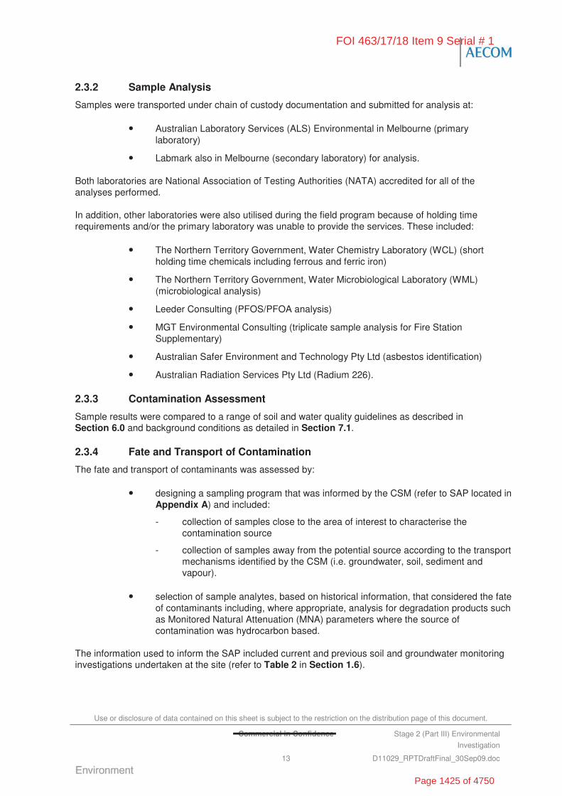
Use or disclosure of data contained on this sheet is subject to the restriction on the distribution page of this document.
Commercial in Confidence Stage 2 (Part III) Environmental
Investigation
13 D11029_RPTDraftFinal_30Sep09.doc
2.3.2 Sample Analysis
Samples were transported under chain of custody documentation and submitted for analysis at:
• Australian Laboratory Services (ALS) Environmental in Melbourne (primary laboratory)
• Labmark also in Melbourne (secondary laboratory) for analysis.
Both laboratories are National Association of Testing Authorities (NATA) accredited for all of the analyses performed.
In addition, other laboratories were also utilised during the field program because of holding time requirements and/or the primary laboratory was unable to provide the services. These included:
• The Northern Territory Government, Water Chemistry Laboratory (WCL) (short holding time chemicals including ferrous and ferric iron)
• The Northern Territory Government, Water Microbiological Laboratory (WML) (microbiological analysis)
• Leeder Consulting (PFOS/PFOA analysis)
• MGT Environmental Consulting (triplicate sample analysis for Fire Station Supplementary)
• Australian Safer Environment and Technology Pty Ltd (asbestos identification)
• Australian Radiation Services Pty Ltd (Radium 226).
2.3.3 Contamination Assessment
Sample results were compared to a range of soil and water quality guidelines as described in Section 6.0 and background conditions as detailed in Section 7.1.
2.3.4 Fate and Transport of Contamination
The fate and transport of contaminants was assessed by:
• designing a sampling program that was informed by the CSM (refer to SAP located in Appendix A) and included:
- collection of samples close to the area of interest to characterise the contamination source
- collection of samples away from the potential source according to the transport mechanisms identified by the CSM (i.e. groundwater, soil, sediment and vapour).
• selection of sample analytes, based on historical information, that considered the fate of contaminants including, where appropriate, analysis for degradation products such as Monitored Natural Attenuation (MNA) parameters where the source of contamination was hydrocarbon based.
The information used to inform the SAP included current and previous soil and groundwater monitoring investigations undertaken at the site (refer to Table 2 in Section 1.6).
FOI 463/17/18 Item 9 Serial # 1
Page 1425 of 4750

Use or disclosure of data contained on this sheet is subject to the restriction on the distribution page of this document.
Commercial in Confidence Stage 2 (Part III) Environmental
Investigation
14 D11029_RPTDraftFinal_30Sep09.doc
2.4 Risk Considerations
2.4.1 Definition of ‘True’ Risk
The project objectives required establishment of the ’true‘ risk to Defence associated with each area of interest as a basis for developing management strategies.
An assessment of the ‘true’ risk to Defence associated with the contamination identified at RAAF Tindal was undertaken using the Defence CRAT (Defence, 2007). In determining the ’true‘ risk using the CRAT, the nature and extent of contamination at each area of interest was assessed and described with reference to the CSM. Particular consideration was given to risk factors such as contamination exposed at the surface (i.e. asbestos containing materials (ACM)) or in migration pathways such as groundwater or drainage lines. Based on the preliminary review of receptors and exposure pathways outlined in Section 4.0, the dominant risk issues that would drive any remedial or management activities at the site were identified. These risks were evaluated in the context of the overall CRAT. The Defence CRAT framework generally adopts the AS/NZS 4360:1999 Risk Management approach by assessing likelihood and consequence scales based upon probabilities of occurrence and impacts upon Defence’s operations.
2.4.2 The Contamination Risk Assessment Tool
The Defence CRAT method is based on the assessment of:
• the consequences associated with contamination at a given area of interest if Defence does nothing
• the likelihood of the identified consequences occurring.
Seven risk dimensions are considered by the CRAT for the assessment of risks to Defence. The risk dimensions are presented Table 3.
Table 3: Risk Dimensions for Contaminated Site Risk Assessment
Risk Dimension Description
Capability Capacity of the facility to support the user unit in delivery of its primary outputs.
Impact on the ability of the Australian Defence Force (ADF) to protect Australia and fulfil its national security obligations.
Impact on the ADF’s ability to train and equip for war and for the conduct of peacetime operations.
Impact on the ability of Defence to develop its capability as detailed in the Defence White Paper.
Impact on civil (non-Defence) capability as a consideration for shared facilities.
Occupational Health and Safety (Staff and Public)
Impact on the physical and psychological well being of military and Defence employees, contractors, communities in Defence regions and the public in general.
Legislative Compliance Compliance with regulatory requirements and the impact of failing to comply, including but not limited to Federal, State, Territory, local legislation, foreign treaties, Indigenous land use agreements, Defence Instructions or Defence Policy.
FOI 463/17/18 Item 9 Serial # 1
Page 1426 of 4750
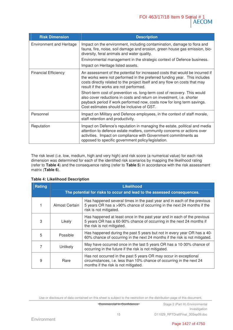
Use or disclosure of data contained on this sheet is subject to the restriction on the distribution page of this document.
Commercial in Confidence Stage 2 (Part III) Environmental
Investigation
15 D11029_RPTDraftFinal_30Sep09.doc
Risk Dimension Description
Environment and Heritage Impact on the environment, including contamination, damage to flora and fauna, fire, noise, soil damage and erosion, green house gas emission, bio-diversity, feral animals and water quality.
Environmental management in the strategic context of Defence business.
Impact on Heritage listed assets.
Financial Efficiency An assessment of the potential for increased costs that would be incurred if the works were not performed in the preferred funding year. This includes costs directly related to the project itself and any flow on costs that may result if the works are not performed.
Short-term cost of prevention vs. long-term cost of recovery. This would also cover reductions in costs and return on investment, i.e. shorter payback period if work performed now, costs now for long term savings. Cost estimates should be inclusive of GST.
Personnel Impact on Military and Defence employees, in the context of staff morale, staff retention and productivity.
Reputation Impact on Defence’s reputation in managing the estate, political and media attention to defence estate matters, community concerns or actions over activities. Impact on compliance with Government commitments as opposed to specific government policy/legislation.
The risk level (i.e. low, medium, high and very high) and risk score (a numerical value) for each risk dimension was determined for each of the identified risk scenarios by mapping the likelihood rating (refer to Table 4) and the consequence rating (refer to Table 5) in accordance with the risk assessment matrix (Table 6).
Table 4: Likelihood Description
Rating Likelihood
The potential for risks to occur and lead to the assessed consequences.
1 Almost Certain Has happened several times in the past year and in each of the previous 5 years OR has a >90% chance of occurring in the next 24 months if the risk is not mitigated.
3 Likely Has happened at least once in the past year and in each of the previous 5 years OR has a 60-90% chance of occurring in the next 24 months if the risk is not mitigated.
5 Possible Has happened during the past 5 years but not in every year OR has a 40-60% chance of occurring in the next 24 months if the risk is not mitigated.
7 Unlikely May have occurred once in the last 5 years OR has a 10-30% chance of occurring in the future if the risk is not mitigated.
9 Rare Has not occurred in the past 5 years OR may occur in exceptional circumstances, i.e. less than 10% chance of occurring in the next 24 months if the risk is not mitigated.
FOI 463/17/18 Item 9 Serial # 1
Page 1427 of 4750

Use or disclosure of data contained on this sheet is subject to the restriction on the distribution page of this document.
Commercial in Confidence Stage 2 (Part III) Environmental Investigation
16 D11029_RPTDraftFinal_30Sep09.doc
Table 5: Risk Dimension Consequence Description
Rating Capability OHS Legislative Compliance
Environment and Heritage
Financial Efficiency
Personnel Reputation
1
(Sev
ere)
All activities cease AND unable to conduct missions or training activities OR all activities cease AND major unacceptable delays in delivery of capability
AND
For major assets resumption not possible within 24 hours
For important assets resumption not possible within 7 days.
For support assets resumption not possible within 28 days.
One or more fatalities or life threatening injuries or illness
OR
Public or staff exposed to a severe, adverse long-term health impact or life threatening hazard.
Potential large-scale class action
AND/OR
Prosecution with maximum fine imposed.
Irreversible and extensive damage is caused to a World Heritage Listed, a Commonwealth Heritage Listed, a National Heritage Listed or a Defence Heritage Listed area or asset
OR
Irreversible and extensive damage is caused to a Matter of National Environmental Significance under the EPBC Act
OR
Irreversible and extensive damage is caused to the Environment
OR
Contamination levels result in acute toxicity to receptors (NEPM 1999)
OR
Severe impact on Defence’s ability to create a sustainable environment for future use.
Cost Risks (these include management of the site, remediation now and in the future and loss of capability) associated with the site would be severe (exceed $10 M).
Serious negative affect on staff morale effecting all staff associated with the structure, with significant loss of productivity, > 5 days lost
OR
A high number (>80%) of the affected staff are highly likely to be re-considering their continued service or employment within Defence
OR
Industrial action is about to be taken.
Detrimental international media reports
OR
Subject of international government attention
OR
Non realisation of a government commitment.
FOI 463/17/18 Item 9 Serial # 1
Page 1428 of 4750

Use or disclosure of data contained on this sheet is subject to the restriction on the distribution page of this document.
Commercial in Confidence Stage 2 (Part III) Environmental Investigation
17 D11029_RPTDraftFinal_30Sep09.doc
Rating Capability OHS Legislative Compliance
Environment and Heritage
Financial Efficiency
Personnel Reputation
6
(Maj
or)
Some activities curtained
AND
Missions or training activities can be conducted however in a significantly degraded state
AND
For major assets resumption not possible within 24 hours.
For important assets resumption not possible within 7 days.
For support assets resumption not possible within 28 days.
One or more major injuries or illness requiring major surgery or resulting in permanent disablement
OR
Public or staff exposed to a hazard that results in major surgery, permanent disablement, or permanent adverse health effects.
High profile legal challenge AND/OR prosecution with 50% to maximum fine imposed.
Irreversible and extensive damage is caused to a non Heritage listed area or asset
OR
Irreversible and extensive damage is caused to a non environmentally significant area or asset
OR
Significant damage is caused to a Heritage Listed area or Asset from which it will take up to 10 years to recover
OR
Significant damage is caused to the environment or asset from which it will take up to 10 year to recover
OR
Contamination levels results in observable impacts on receptors as defined in the NEPM
OR
Impact on Defence’s ability to manage the environment in a sustainable manner.
Cost Risks (these include management of the site, remediation now and in the future and loss of capability) associated with the site would be major ($5 M up to $10 M).
Major negative affect on staff morale, affecting more than half the staff associated with the structure with major loss of productivity, > 1 day lost.
Over 50% of affected staff are likely to be reconsidering their continued service or employment within Defence
OR
Threat of Industrial Action.
Sustained detrimental national or state media reports
OR
Subject of a number of parliamentary questions and ministerial
OR
Sustained community outrage.
FOI 463/17/18 Item 9 Serial # 1
Page 1429 of 4750
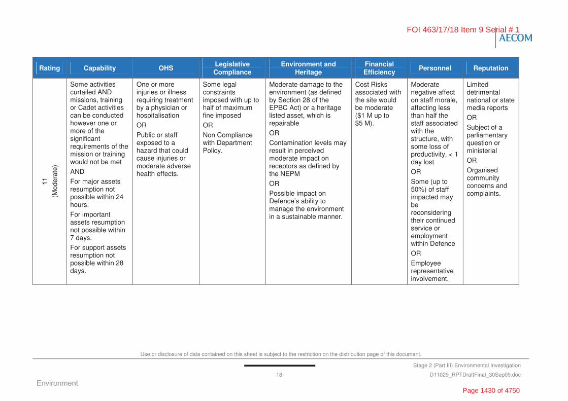
Use or disclosure of data contained on this sheet is subject to the restriction on the distribution page of this document.
Stage 2 (Part III) Environmental Investigation
18 D11029_RPTDraftFinal_30Sep09.doc
Rating Capability OHS Legislative Compliance
Environment and Heritage
Financial Efficiency
Personnel Reputation
11
(Mod
erat
e)
Some activities curtailed AND missions, training or Cadet activities can be conducted however one or more of the significant requirements of the mission or training would not be met
AND
For major assets resumption not possible within 24 hours.
For important assets resumption not possible within 7 days.
For support assets resumption not possible within 28 days.
One or more injuries or illness requiring treatment by a physician or hospitalisation
OR
Public or staff exposed to a hazard that could cause injuries or moderate adverse health effects.
Some legal constraints imposed with up to half of maximum fine imposed
OR
Non Compliance with Department Policy.
Moderate damage to the environment (as defined by Section 28 of the EPBC Act) or a heritage listed asset, which is repairable
OR
Contamination levels may result in perceived moderate impact on receptors as defined by the NEPM
OR
Possible impact on Defence’s ability to manage the environment in a sustainable manner.
Cost Risks associated with the site would be moderate ($1 M up to $5 M).
Moderate negative affect on staff morale, affecting less than half the staff associated with the structure, with some loss of productivity, < 1 day lost
OR
Some (up to 50%) of staff impacted may be reconsidering their continued service or employment within Defence
OR
Employee representative involvement.
Limited detrimental national or state media reports
OR
Subject of a parliamentary question or ministerial
OR
Organised community concerns and complaints.
FOI 463/17/18 Item 9 Serial # 1
Page 1430 of 4750

Use or disclosure of data contained on this sheet is subject to the restriction on the distribution page of this document.
Commercial in Confidence Stage 2 (Part III) Environmental Investigation
19 D11029_RPTDraftFinal_30Sep09.doc
Rating Capability OHS Legislative Compliance
Environment and Heritage
Financial Efficiency
Personnel Reputation
16
(Min
or)
Minimal activities curtained AND missions, training or Cadet activities can be conducted with minor degradation to several missions or training requirements
OR
Minor delays or minor performance degradation.
One or more injuries or illness requiring treatment by a qualified first aid person
OR
Exposed of public and staff to a hazard that could cause minor injuries or minor adverse health effects.
Minor technical legal challenge OR legal breach.
Minor damage to the environment or heritage asset that is immediately contained on-site. It will take less than 2 years for the resource or asset to fully recover
OR
Disturbance to scarce or sensitive environmental ore heritage resources
OR
Contamination levels exceed HILs and EILs as defined by the NEPM
OR
Minor impacts on Defence’s ability to manage the environment in a sustainable manner.
Cost Risks associated with the site would be minor ($0.5 M up to $1 M).
Minimal affect on staff morale, affecting a small number (<25%) of the staff associated with the structure with possible minor productivity loss
OR
Staff are unlikely to be re-considering their continued service or employment within Defence.
High profile detrimental local media reports
OR
Subject of local government action
OR
Random substantiated complaints from the community.
FOI 463/17/18 Item 9 Serial # 1
Page 1431 of 4750
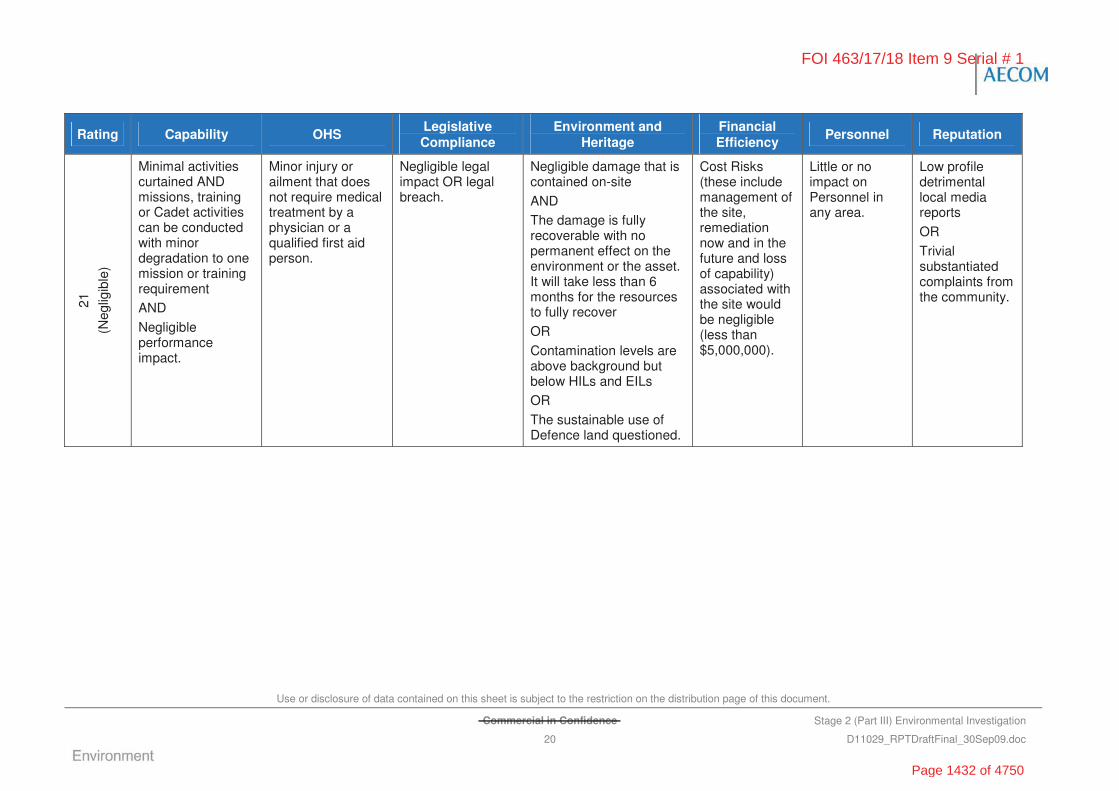
Use or disclosure of data contained on this sheet is subject to the restriction on the distribution page of this document.
Commercial in Confidence Stage 2 (Part III) Environmental Investigation
20 D11029_RPTDraftFinal_30Sep09.doc
Rating Capability OHS Legislative Compliance
Environment and Heritage
Financial Efficiency
Personnel Reputation
21
(Neg
ligib
le)
Minimal activities curtained AND missions, training or Cadet activities can be conducted with minor degradation to one mission or training requirement
AND
Negligible performance impact.
Minor injury or ailment that does not require medical treatment by a physician or a qualified first aid person.
Negligible legal impact OR legal breach.
Negligible damage that is contained on-site
AND
The damage is fully recoverable with no permanent effect on the environment or the asset. It will take less than 6 months for the resources to fully recover
OR
Contamination levels are above background but below HILs and EILs
OR
The sustainable use of Defence land questioned.
Cost Risks (these include management of the site, remediation now and in the future and loss of capability) associated with the site would be negligible (less than $5,000,000).
Little or no impact on Personnel in any area.
Low profile detrimental local media reports
OR
Trivial substantiated complaints from the community.
FOI 463/17/18 Item 9 Serial # 1
Page 1432 of 4750
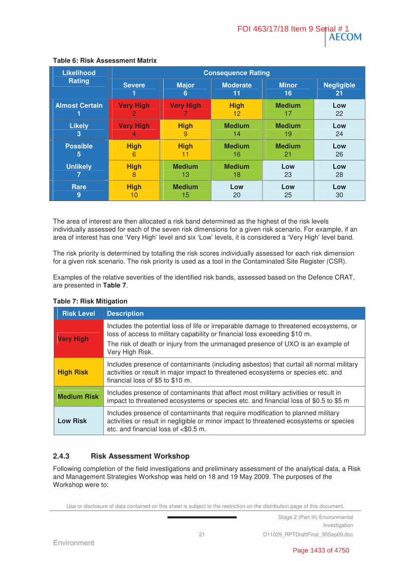
Use or disclosure of data contained on this sheet is subject to the restriction on the distribution page of this document.
Stage 2 (Part III) Environmental
Investigation
21 D11029_RPTDraftFinal_30Sep09.doc
Table 6: Risk Assessment Matrix
Consequence Rating Likelihood Rating
Severe 1
Major 6
Moderate 11
Minor 16
Negligible 21
Almost Certain 1
Very High 2
Very High 7
High 12
Medium 17
Low 22
Likely 3
Very High 4
High 9
Medium 14
Medium 19
Low 24
Possible 5
High 6
High 11
Medium 16
Medium 21
Low 26
Unlikely 7
High 8
Medium 13
Medium 18
Low 23
Low 28
Rare 9
High 10
Medium 15
Low 20
Low 25
Low 30
The area of interest are then allocated a risk band determined as the highest of the risk levels individually assessed for each of the seven risk dimensions for a given risk scenario. For example, if an area of interest has one ‘Very High’ level and six ‘Low’ levels, it is considered a ‘Very High’ level band.
The risk priority is determined by totalling the risk scores individually assessed for each risk dimension for a given risk scenario. The risk priority is used as a tool in the Contaminated Site Register (CSR).
Examples of the relative severities of the identified risk bands, assessed based on the Defence CRAT, are presented in Table 7.
Table 7: Risk Mitigation
Risk Level Description
Very High
Includes the potential loss of life or irreparable damage to threatened ecosystems, or loss of access to military capability or financial loss exceeding $10 m.
The risk of death or injury from the unmanaged presence of UXO is an example of Very High Risk.
High Risk Includes presence of contaminants (including asbestos) that curtail all normal military activities or result in major impact to threatened ecosystems or species etc. and financial loss of $5 to $10 m.
Medium Risk Includes presence of contaminants that affect most military activities or result in impact to threatened ecosystems or species etc. and financial loss of $0.5 to $5 m
Low Risk Includes presence of contaminants that require modification to planned military activities or result in negligible or minor impact to threatened ecosystems or species etc. and financial loss of <$0.5 m.
2.4.3 Risk Assessment Workshop
Following completion of the field investigations and preliminary assessment of the analytical data, a Risk and Management Strategies Workshop was held on 18 and 19 May 2009. The purposes of the Workshop were to:
FOI 463/17/18 Item 9 Serial # 1
Page 1433 of 4750
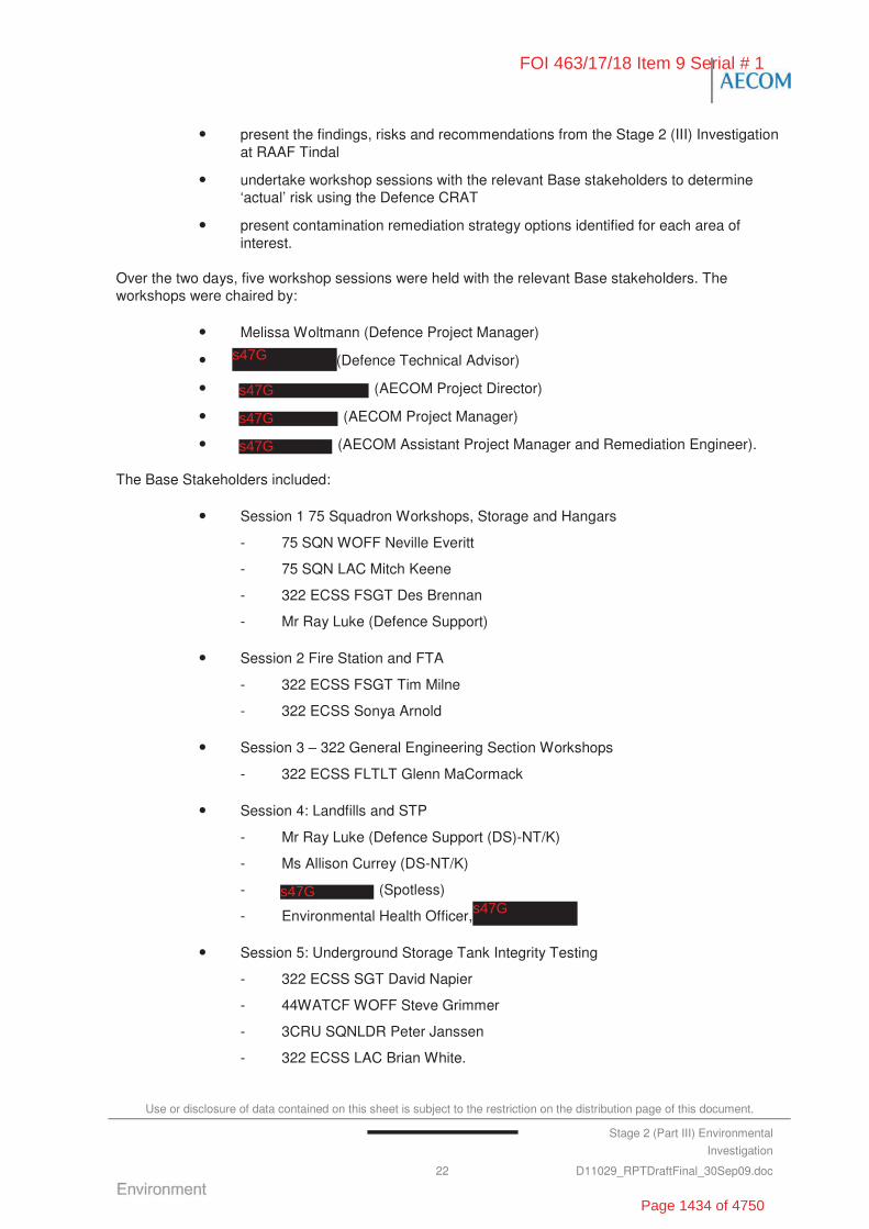
Use or disclosure of data contained on this sheet is subject to the restriction on the distribution page of this document.
Stage 2 (Part III) Environmental
Investigation
22 D11029_RPTDraftFinal_30Sep09.doc
• present the findings, risks and recommendations from the Stage 2 (III) Investigation at RAAF Tindal
• undertake workshop sessions with the relevant Base stakeholders to determine ‘actual’ risk using the Defence CRAT
• present contamination remediation strategy options identified for each area of interest.
Over the two days, five workshop sessions were held with the relevant Base stakeholders. The workshops were chaired by:
• Melissa Woltmann (Defence Project Manager)
• (Defence Technical Advisor)
• (AECOM Project Director)
• (AECOM Project Manager)
• (AECOM Assistant Project Manager and Remediation Engineer).
The Base Stakeholders included:
• Session 1 75 Squadron Workshops, Storage and Hangars
- 75 SQN WOFF Neville Everitt
- 75 SQN LAC Mitch Keene
- 322 ECSS FSGT Des Brennan
- Mr Ray Luke (Defence Support)
• Session 2 Fire Station and FTA
- 322 ECSS FSGT Tim Milne
- 322 ECSS Sonya Arnold
• Session 3 – 322 General Engineering Section Workshops
- 322 ECSS FLTLT Glenn MaCormack
• Session 4: Landfills and STP
- Mr Ray Luke (Defence Support (DS)-NT/K)
- Ms Allison Currey (DS-NT/K)
- (Spotless)
- Environmental Health Officer,
• Session 5: Underground Storage Tank Integrity Testing
- 322 ECSS SGT David Napier
- 44WATCF WOFF Steve Grimmer
- 3CRU SQNLDR Peter Janssen
- 322 ECSS LAC Brian White.
FOI 463/17/18 Item 9 Serial # 1
s47G
s47G
s47G
s47G
s47G
s47G
Page 1434 of 4750
Use or disclosure of data contained on this sheet is subject to the restriction on the distribution page of this document.
Stage 2 (Part III) Environmental
Investigation
23 D11029_RPTDraftFinal_30Sep09.doc
A copy of the workshop agenda has been provided in Appendix B.
2.5 Remediation/Management Considerations
The evaluation of remediation/management options for the project generally followed the guidance of ANZECC/NHMRC (1992), later reproduced in the introduction to the NEPM (1999). The recommended preferred hierarchy of remediation and management actions is:
• if practicable, on-site treatment of the contamination so that the contaminant is either destroyed or the associated hazard is reduced to an acceptable level, or
• offsite treatment of excavated soil so that the contaminant is either destroyed or the associated hazard is reduced to an acceptable level, after which the soil is returned to the site, or
• if these options cannot be implemented (impracticable), then:
- consolidation and isolation of soil on site by containing with properly designed barriers
- removal to an approved site or facility, followed where necessary, by replacement with appropriate material
- where assessment indicates remediation would have no net environmental benefit or would have a net adverse environmental effect, implementation of an appropriate management strategy.
Note also that the ANZECC (1992) guideline indicates that other options to be considered include:
• choosing a less sensitive land use to minimise the need for remedial works which may include partial remediation
• as implied by NEPM (1999), leaving contaminated material in-situ providing there is no immediate danger to the environment or community and the site has appropriate controls in place.
The management options considered for each of the areas of interest investigated are summarised in the individual site summary sections (Sections 8.0 through to Section 19.0).
2.6 Reporting
This report is intended to be read in conjunction with reports documenting the outcomes of the various previous investigations identified in Section 1.6, Table 9. The reader should refer to these earlier reports listed in Section 1.6 for additional background data. For the purpose of limiting the volume of this report, previous site history and investigation findings have been summarised and not repeated in any substantial detail.
Reports produced by AECOM and their sub-consultants as part of the Stage 2 (III) Investigations have been summarised in the relevant sections of this report. The following reports have been reproduced in the Appendix Section of this report:
• Geophysical Investigation of RAAF Tindal Landfills (G-tek Australia Pty Limited, 2008) (Appendix C)
• Human Health Risk Assessment at RAAF Tindal MTOF Building 333 (AECOM, 2009a) (Appendix D)
• Human Health and Ecological Risk Assessment at RAAF Tindal Fire Training Area (AECOM, 2009b) (Appendix E)
FOI 463/17/18 Item 9 Serial # 1
Page 1435 of 4750

Use or disclosure of data contained on this sheet is subject to the restriction on the distribution page of this document.
Commercial in Confidence Stage 2 (Part III) Environmental
Investigation
24 D11029_RPTDraftFinal_30Sep09.doc
• Equipment Integrity Test Report, RAAF Base Tindal (JFTA Environmental Solutions, 2008) (Appendix F).
FOI 463/17/18 Item 9 Serial # 1
Page 1436 of 4750
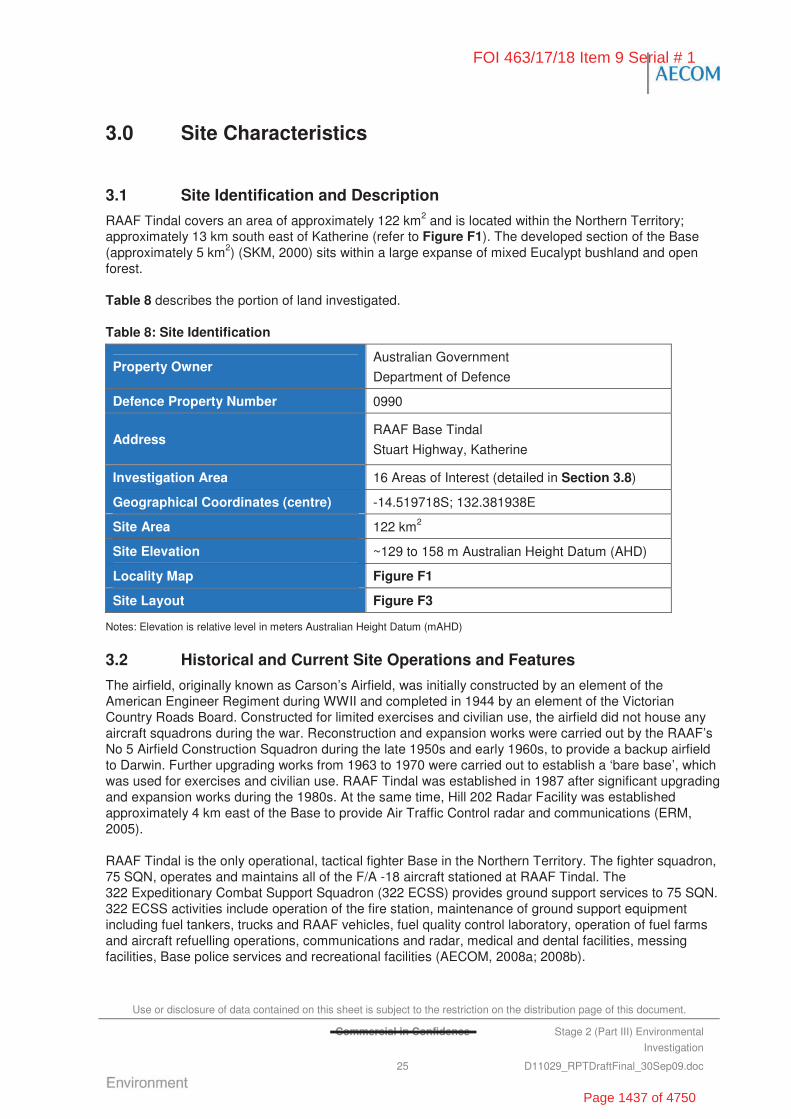
Use or disclosure of data contained on this sheet is subject to the restriction on the distribution page of this document.
Commercial in Confidence Stage 2 (Part III) Environmental
Investigation
25 D11029_RPTDraftFinal_30Sep09.doc
3.0 Site Characteristics
3.1 Site Identification and Description
RAAF Tindal covers an area of approximately 122 km2 and is located within the Northern Territory; approximately 13 km south east of Katherine (refer to Figure F1). The developed section of the Base (approximately 5 km2) (SKM, 2000) sits within a large expanse of mixed Eucalypt bushland and open forest.
Table 8 describes the portion of land investigated.
Table 8: Site Identification
Property Owner Australian Government
Department of Defence
Defence Property Number 0990
Address RAAF Base Tindal
Stuart Highway, Katherine
Investigation Area 16 Areas of Interest (detailed in Section 3.8)
Geographical Coordinates (centre) -14.519718S; 132.381938E
Site Area 122 km2
Site Elevation ~129 to 158 m Australian Height Datum (AHD)
Locality Map Figure F1
Site Layout Figure F3
Notes: Elevation is relative level in meters Australian Height Datum (mAHD)
3.2 Historical and Current Site Operations and Features
The airfield, originally known as Carson’s Airfield, was initially constructed by an element of the American Engineer Regiment during WWII and completed in 1944 by an element of the Victorian Country Roads Board. Constructed for limited exercises and civilian use, the airfield did not house any aircraft squadrons during the war. Reconstruction and expansion works were carried out by the RAAF’s No 5 Airfield Construction Squadron during the late 1950s and early 1960s, to provide a backup airfield to Darwin. Further upgrading works from 1963 to 1970 were carried out to establish a ‘bare base’, which was used for exercises and civilian use. RAAF Tindal was established in 1987 after significant upgrading and expansion works during the 1980s. At the same time, Hill 202 Radar Facility was established approximately 4 km east of the Base to provide Air Traffic Control radar and communications (ERM, 2005).
RAAF Tindal is the only operational, tactical fighter Base in the Northern Territory. The fighter squadron, 75 SQN, operates and maintains all of the F/A -18 aircraft stationed at RAAF Tindal. The 322 Expeditionary Combat Support Squadron (322 ECSS) provides ground support services to 75 SQN. 322 ECSS activities include operation of the fire station, maintenance of ground support equipment including fuel tankers, trucks and RAAF vehicles, fuel quality control laboratory, operation of fuel farms and aircraft refuelling operations, communications and radar, medical and dental facilities, messing facilities, Base police services and recreational facilities (AECOM, 2008a; 2008b).
FOI 463/17/18 Item 9 Serial # 1
Page 1437 of 4750
Use or disclosure of data contained on this sheet is subject to the restriction on the distribution page of this document.
Commercial in Confidence Stage 2 (Part III) Environmental
Investigation
26 D11029_RPTDraftFinal_30Sep09.doc
The main site features and structures at RAAF Tindal (refer to Figure F3) are:
• RAAF Air Movements facility
• radar communication tower at Hill Radar 202
• civilian airport (leased by Katherine City Council)
• Frontline canteen and service station (leased)
• vehicle maintenance areas
• hazardous materials storage
• Security Dog Complex
• ordnance preparation and storage areas
• Ordnance Loading Aprons
• 75 Squadron workshops and laboratories
• Fuel Farm No. 1
• Fuel Farm No. 2
• Fire Brigade and Search and Rescue Section
• Fire Training Area
• STP and Horse Paddock
• medical facilities
• married quarters
• messes and football oval
• golf course.
Prior to the development of RAAF Tindal for Defence use, it was primarily used for agricultural purposes, including livestock production and horticultural use. Agriculture is currently a significant surrounding land use to the Base (SKM, 2000).
3.3 Regional Meteorology
RAAF Tindal lies within the coastal monsoonal region of northern Australia. The area experiences a wet-dry tropical climate pattern, with a distinct, monsoonal wet season between November and April and a dry season between May and October.
The climatic data recorded by the Bureau of Meteorology at the RAAF Tindal weather station (014932) provides the following climatic information:
• average maximum temperature of 33.8 oC, ranging from 29.8 oC in June to 37.6 oC in October
• average minimum temperature of 20.5 oC, ranging from 13.5 oC in July to 25 oC in November
• average annual rainfall of 1,092.9 mm, with January and February typically the wettest months.
FOI 463/17/18 Item 9 Serial # 1
Page 1438 of 4750
Use or disclosure of data contained on this sheet is subject to the restriction on the distribution page of this document.
Stage 2 (Part III) Environmental
Investigation
27 D11029_RPTDraftFinal_30Sep09.doc
3.4 Topography and Hydrology
The Base is located within generally flat lowland open Eucalypt bushland and scrubland interspersed with some small hills and limestone outcrops (ERM, 2005). Elevations at the site range between 130 and 140 m AHD (SKM, 2007), with a general gentle slope towards Tindal Creek in the south west (note in particular that the FTA (NT0064) is approximately 10 m lower in elevation than the MEOMS area (NT0072)) (GHD, 2008).
Most of RAAF Tindal lies within the Tindal Creek catchment area, within which the main surface water body is Tindal Creek. The source of Tindal Creek, which is an ephemeral southern tributary of the Katherine River (SKM, 2007), is approximately 20 km south of the Base (GHD, 2008). The creek enters the Base from the south, veers northwest, south of the Horse Paddock (NT0062), and continues south of the main runway before leaving the Base under the Stuart Highway to later join the Katherine River downstream of the Katherine Township (AECOM, 2008a). Tindal Creek is fed by:
• surface water runoff from bushland and scrubland both within and outside the Base (AECOM, 2008a)
• a series of springs located around the south-eastern section of the Base, which flow for several months after the end of the wet season along concrete channels (GHD, 2008).
It is important to note that RAAF Tindal lies in the lower reaches of the Kakadu (Stage I and Stage III) catchment area, which is a Ramsar listed wetland of international significance (AECOM, 2008b). The Kakadu Ramsar Site is a mosaic of contiguous wetlands comprising the catchments of two large river systems, East and South Alligator Rivers, seasonal creeks and the lower reaches of the East Alligator River. The floodplains and other wetlands within the Kakadu (Stage I and Stage III) support about 1 million waterbirds of over 60 species, as well as many other vertebrate and invertebrate species.
3.5 Geology and Hydrology
The Tindal area is described within the 1:250,000 Geological Map Series for Katherine SD 53-9, (1994) as being part of the Daly Basin which is dominated by lowland plains consisting of limestone, mudstone, dolostone and minor sandstone deposited in peritidal to open shelf marine environments. Most of the limestone in the Tindal area is overlain by Quaternary laterite ferricrete and residual loamy sands (AECOM, 2008c).
Geology and lithology information reported in previous assessments (SKM, 2001) describes the Tindal area as belonging to the Cambrian land system, which is an area of extensive stony erosional plains. These erosional karst plains are characterised by loamy red earths, with the occasional limestone outcrop, scattered sinkholes, shallow depressions and stream channels incised in bedrock. A number of soil groups have been identified in the Tindal area, and include the following broad groups (in order of occurrence):
• red earths - sandy and loamy red earths derived from silicified sandstone and limestone
• earthy sands - dark-reddish brown, loose, clayey sand profile and are generally well-drained
• yellow earths - similar to red earths but tend to become water logged during the wet season
• lateritic podzols (used extensively as borrow pits during the construction of RAAF Tindal) – sandy to mottled yellow-brown to red clay with ironstone present
FOI 463/17/18 Item 9 Serial # 1
Page 1439 of 4750

Use or disclosure of data contained on this sheet is subject to the restriction on the distribution page of this document.
Stage 2 (Part III) Environmental
Investigation
28 D11029_RPTDraftFinal_30Sep09.doc
• lithosols - containing high amounts of rock fragments and confined to areas where rock outcrops are common
• grey-brown clays - clay textured soils that crack widely and are very dry.
The Aquifer Formation underlying RAAF Tindal can be summarised as follows:
• RAAF Tindal and the Katherine region is underlain by the Daly River Group known throughout the region as the ‘Tindall Limestone’. The Tindall Limestone is the basal formation of the Daly River Group (Tickell, 2005).
• The Tindall aquifer at RAAF Tindal can be described as a generally deep unconfined aquifer ranging in depth from the surface (in the Katherine River area) down to approximately 650 mAHD around 50 km south west of Katherine.
• The Tindall Limestone Aquifer is over 100 km wide and over 300 km long.
• The Tindall Limestone Aquifer is largely overlain by the Oolloo and Jinduckin geological formation, as water does not infiltrate through them into the TIndall Limestone.
• The Tindall Limestone Aquifer is observed close to or at the surface, particularly in lower lying areas adjacent to the major rivers (Tickell, 2005).
• Recharge to the Tindal Aquifer only occurs in areas where it is in direct contact with the ground surface, as occurs in the Katherine region (NRETAS, 2009).
• The average recharge to the Tindall Limestone Aquifer is 74,000 ML/yr (as determined by hydrologic model and rainfall records from 1957-2006). Of this. 64,000 ML/yr is from rainfall recharge and 10,000 ML/yr from the sandstone plateau, north of Katherine (NRETAS, 2009).
• The Jinduckin Formation, which is the cavernous limestone aquifer (karst formation), is perched over the Tindall Limestone Aquifer and consists of widespread outcropping of the limestone, sinkholes and caverns throughout the area.
• Tindal Creek is understood to flow into the Katherine River, which is an important drinking water source for the local community and surrounding area. The Tindall Limestone Aquifer also provides base flow to the Katherine River.
• Groundwater flow in the region of RAAF Tindal is towards the Katherine River to the north-west (at an estimated flow rate of 90 – 180 ML/day).
• During the Stage 2 (III) Investigations, groundwater flow across the Base was determined in a westerly direction towards Tindal Creek.
Figure 1, provides a computerised conceptual model of the Tindall Limestone Aquifer (Katherine) system. The model shows the dynamic interaction of the surface water and groundwater systems and accounts for ‘basin wide’ water usage in terms of impact on river flows, spring discharges and water availability to groundwater dependent ecosystems (NRETAS, 2009).
FOI 463/17/18 Item 9 Serial # 1
Page 1440 of 4750

Use or disclosure of data contained on this sheet is subject to the restriction on the distribution page of this document.
Commercial in Confidence Stage 2 (Part III) Environmental
Investigation
29 D11029_RPTDraftFinal_30Sep09.doc
Figure 1: Conceptual Groundwater Model for the Katherine Region
(Source: NRETAS, 2009. Background: Water Allocation Plan – Tindall Limestone Aquifer, Katherine. Pg. 65)
The Katherine Water Control District is largely made up the unconfined section of the Tindall Limestone Aquifer and is clearly demarcated within the Daly River Catchment Aquifer Formation. The Township obtains its drinking water from the Katherine River and supplements its supply with groundwater from the extraction bore fields within the Katherine Water Control District. RAAF Tindal potable water is supplied by the Katherine Township. In addition to this supply, onsite extraction bores, which obtain groundwater resources directly from the Tindall Limestone, are primarily used for irrigation purposes (AECOM, 2008a).
Groundwater sensitivity is considered to be high due to the karst conditions of the Tindall Limestone Formation likely providing direct conduit connectivity from the Base to both onsite groundwater extraction bores, down gradient springs and bores, and subsequently the Katherine River (AECOM, 2008a).
Bore information reported in a previous Stage 2 Investigation at the Base (ERM, 2007a) identified 92 registered bores within a 2 kilometre radius of the Base; approximately 80% of these were registered for stock and domestic use and 20% were registered for irrigation/industrial use (GHD, 2008). Of these, five bores are actively used for groundwater extraction (AECOM, 2008c).
3.6 Surrounding Land Uses
The land uses surrounding the Base comprise (AECOM, 2008a):
• to the north, the Stuart Highway and grazing and rural/residential land (including Jarrahdale Station)
• to the east, partially disturbed bushland, rural land and mango farms; and the Township of Katherine approximately 13 km to the east-north east
• to the south, the Cutta Cutta Caves National Park
• to the west, grazing land and a quarry, from which blue metal road base is mined.
FOI 463/17/18 Item 9 Serial # 1
Page 1441 of 4750
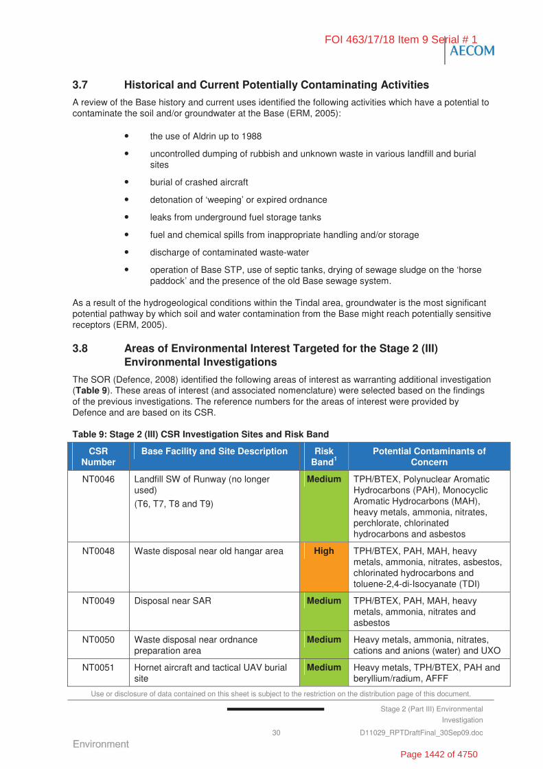
Use or disclosure of data contained on this sheet is subject to the restriction on the distribution page of this document.
Stage 2 (Part III) Environmental
Investigation
30 D11029_RPTDraftFinal_30Sep09.doc
3.7 Historical and Current Potentially Contaminating Activities
A review of the Base history and current uses identified the following activities which have a potential to contaminate the soil and/or groundwater at the Base (ERM, 2005):
• the use of Aldrin up to 1988
• uncontrolled dumping of rubbish and unknown waste in various landfill and burial sites
• burial of crashed aircraft
• detonation of ‘weeping’ or expired ordnance
• leaks from underground fuel storage tanks
• fuel and chemical spills from inappropriate handling and/or storage
• discharge of contaminated waste-water
• operation of Base STP, use of septic tanks, drying of sewage sludge on the ‘horse paddock’ and the presence of the old Base sewage system.
As a result of the hydrogeological conditions within the Tindal area, groundwater is the most significant potential pathway by which soil and water contamination from the Base might reach potentially sensitive receptors (ERM, 2005).
3.8 Areas of Environmental Interest Targeted for the Stage 2 (III) Environmental Investigations
The SOR (Defence, 2008) identified the following areas of interest as warranting additional investigation (Table 9). These areas of interest (and associated nomenclature) were selected based on the findings of the previous investigations. The reference numbers for the areas of interest were provided by Defence and are based on its CSR.
Table 9: Stage 2 (III) CSR Investigation Sites and Risk Band
CSR Number
Base Facility and Site Description Risk Band1
Potential Contaminants of Concern
NT0046 Landfill SW of Runway (no longer used)
(T6, T7, T8 and T9)
Medium TPH/BTEX, Polynuclear Aromatic Hydrocarbons (PAH), Monocyclic Aromatic Hydrocarbons (MAH), heavy metals, ammonia, nitrates, perchlorate, chlorinated hydrocarbons and asbestos
NT0048 Waste disposal near old hangar area High TPH/BTEX, PAH, MAH, heavy metals, ammonia, nitrates, asbestos, chlorinated hydrocarbons and toluene-2,4-di-Isocyanate (TDI)
NT0049 Disposal near SAR Medium TPH/BTEX, PAH, MAH, heavy metals, ammonia, nitrates and asbestos
NT0050 Waste disposal near ordnance preparation area
Medium Heavy metals, ammonia, nitrates, cations and anions (water) and UXO
NT0051 Hornet aircraft and tactical UAV burial site
Medium Heavy metals, TPH/BTEX, PAH and beryllium/radium, AFFF
FOI 463/17/18 Item 9 Serial # 1
Page 1442 of 4750
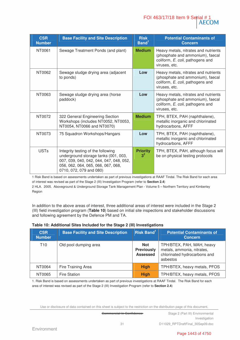
Use or disclosure of data contained on this sheet is subject to the restriction on the distribution page of this document.
Commercial in Confidence Stage 2 (Part III) Environmental
Investigation
31 D11029_RPTDraftFinal_30Sep09.doc
CSR Number
Base Facility and Site Description Risk Band1
Potential Contaminants of Concern
NT0061 Sewage Treatment Ponds (and plant) Medium Heavy metals, nitrates and nutrients (phosphate and ammonium), faecal coliform, E. coli, pathogens and viruses, etc.
NT0062 Sewage sludge drying area (adjacent to ponds)
Low Heavy metals, nitrates and nutrients (phosphate and ammonium), faecal coliform, E. coli, pathogens and viruses, etc.
NT0063 Sewage sludge drying area (horse paddock)
Low Heavy metals, nitrates and nutrients (phosphate and ammonium), faecal coliform, E. coli, pathogens and viruses, etc.
NT0072 322 General Engineering Section Workshops (includes NT0052, NT0053, NT0054, NT0066 and NT0070)
Medium TPH, BTEX, PAH (naphthalene), metallic inorganic and chlorinated hydrocarbons, AFFF
NT0073 75 Squadron Workshops/Hangars Low TPH, BTEX, PAH (naphthalene), metallic inorganic and chlorinated hydrocarbons, AFFF
USTs Integrity testing of the following underground storage tanks (001, 003, 007, 039, 040, 042, 044, 047, 048, 052, 056, 062, 064, 065, 066, 067, 068, 0710, 072, 079 and 080)
Priority 32
TPH, BTEX, PAH, although focus will be on physical testing protocols
1 Risk Band is based on assessments undertaken as part of previous investigations at RAAF Tindal. The Risk Band for each area
of interest was revised as part of the Stage 2 (III) Investigation Program (refer to Section 2.4)
2 HLA. 2005. Aboveground & Underground Storage Tank Management Plan - Volume 5 – Northern Territory and Kimberley
Region
In addition to the above areas of interest, three additional areas of interest were included in the Stage 2 (III) field investigation program (Table 10) based on initial site inspections and stakeholder discussions and following agreement by the Defence PM and TA.
Table 10: Additional Sites Included for the Stage 2 (III) Investigations
CSR Number
Base Facility and Site Description Risk Band1 Potential Contaminants of Concern
T10 Old pool dumping area Not Previously Assessed
TPH/BTEX, PAH, MAH, heavy metals, ammonia, nitrates, chlorinated hydrocarbons and asbestos
NT0064 Fire Training Area High TPH/BTEX, heavy metals, PFOS
NT0065 Fire Station High TPH/BTEX, heavy metals, PFOS
1. Risk Band is based on assessments undertaken as part of previous investigations at RAAF Tindal. The Risk Band for each
area of interest was revised as part of the Stage 2 (III) Investigation Program (refer to Section 2.4)
FOI 463/17/18 Item 9 Serial # 1
Page 1443 of 4750

Use or disclosure of data contained on this sheet is subject to the restriction on the distribution page of this document.
Commercial in Confidence Stage 2 (Part III) Environmental
Investigation
32 D11029_RPTDraftFinal_30Sep09.doc
“This page has been left blank intentionally”
FOI 463/17/18 Item 9 Serial # 1
Page 1444 of 4750
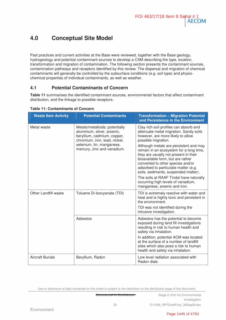
Use or disclosure of data contained on this sheet is subject to the restriction on the distribution page of this document.
Commercial in Confidence Stage 2 (Part III) Environmental
Investigation
33 D11029_RPTDraftFinal_30Sep09.doc
4.0 Conceptual Site Model
Past practices and current activities at the Base were reviewed, together with the Base geology, hydrogeology and potential contaminant sources to develop a CSM describing the type, location, transformation and migration of contamination. The following section presents the contaminant sources, contamination pathways and receptors identified by this review. The dispersal and migration of chemical contaminants will generally be controlled by the subsurface conditions (e.g. soil type) and physio-chemical properties of individual contaminants, as well as weather.
4.1 Potential Contaminants of Concern
Table 11 summarises the identified contaminant sources, environmental factors that affect contaminant distribution, and the linkage to possible receptors.
Table 11: Contaminants of Concern
Waste Item Activity Potential Contaminants Transformation – Migration Potential and Persistence in the Environment
Metal waste Metals/metalloids; potentially aluminium, silver, arsenic, beryllium, cadmium, copper, chromium, iron, lead, nickel, selenium, tin, manganese, mercury, zinc and vanadium.
Clay rich soil profiles can absorb and attenuate metal migration. Sandy soils however, are more likely to allow possible migration.
Although metals are persistent and may remain in an ecosystem for a long time, they are usually not present in their bioavailable form, but are rather converted to other species and/or adsorbed to particulate matter (e.g. soils, sediments, suspended matter).
The soils at RAAF Tindal have naturally occurring high levels of vanadium, manganese, arsenic and iron.
Toluene Di-Isocyanate (TDI) TDI is extremely reactive with water and heat and is highly toxic and persistent in the environment.
TDI was not identified during the intrusive investigation.
Other Landfill waste
Asbestos Asbestos has the potential to become exposed during land fill investigations resulting in risk to human health and safety via inhalation.
In addition, potential ACM was located at the surface of a number of landfill sites which also pose a risk to human health and safety via inhalation.
Aircraft Burials Beryllium, Radon Low level radiation associated with Radon dials
FOI 463/17/18 Item 9 Serial # 1
Page 1445 of 4750

Use or disclosure of data contained on this sheet is subject to the restriction on the distribution page of this document.
Commercial in Confidence Stage 2 (Part III) Environmental
Investigation
34 D11029_RPTDraftFinal_30Sep09.doc
Waste Item Activity Potential Contaminants Transformation – Migration Potential and Persistence in the Environment
Mechanical maintenance (e.g. degreasers), workshop activities, the use of solvents/paints
Volatile Organic Compounds (VOC)
VOCs can migrate within soil and groundwater and create vapours that may pose a potential health risk.
Can be persistent in the environment, however are also subject to biodegradation and attenuation (if conditions are appropriate).
Fuel/oil leaks/spills/waste storage
Light Non-Aqueous Phase Liquids (LNAPL) and Dense Non-Aqueous Phase Liquid (DNAPL)
Non-Aqueous Phase Liquids (NAPL) will migrate vertically and laterally below the water table and may therefore contaminate natural soil particularly sands/silts below the water table.
DNAPLs can migrate along aquitards under gravity and against groundwater flow direction.
LNAPL can volatise and vapour can migrate to the ground surface resulting in exposure.
Hydrocarbons can be persistent in the environment, however are subject to biodegradation and attenuation (if conditions are appropriate). Natural attenuation parameters include methane, manganese and ferrous iron.
Refuelling of aircraft and other vehicles
Leaking oil/fuel/coolants etc
Metals/TPH/MAH/BTEX
Although metals are persistent and may remain in an ecosystem for a long time, they are usually not present in their bioavailable form, but are rather converted to other species and/or adsorbed to particulate matter (e.g., soils, sediments, suspended matter).
Hydrocarbons (TPH/MAH/BTEX) can be persistent in the environment, however are subject to biodegradation and attenuation (if conditions are appropriate).
Aircraft/equipment washing activities including trade waste activities
Detergents/surfactants
Anionic surfactants (Methylene Blue Active Substances (MBAS)), phosphorous, PFOS and PFOA
Detergents and surfactants can migrate in both soil and groundwater and are often more persistent than some of the other CoPC.
Specific contaminants of Concern associated with the historic use of AFFF are PFOS and PFOA.
FOI 463/17/18 Item 9 Serial # 1
Page 1446 of 4750
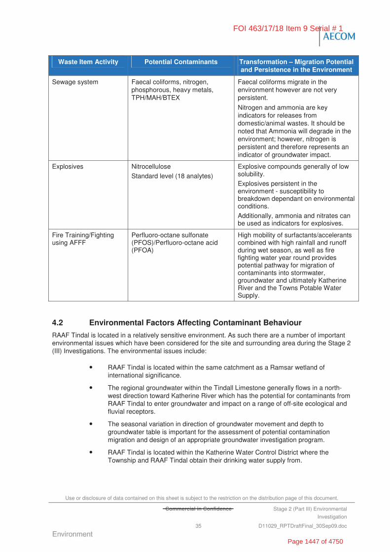
Use or disclosure of data contained on this sheet is subject to the restriction on the distribution page of this document.
Commercial in Confidence Stage 2 (Part III) Environmental
Investigation
35 D11029_RPTDraftFinal_30Sep09.doc
Waste Item Activity Potential Contaminants Transformation – Migration Potential and Persistence in the Environment
Sewage system Faecal coliforms, nitrogen, phosphorous, heavy metals, TPH/MAH/BTEX
Faecal coliforms migrate in the environment however are not very persistent.
Nitrogen and ammonia are key indicators for releases from domestic/animal wastes. It should be noted that Ammonia will degrade in the environment; however, nitrogen is persistent and therefore represents an indicator of groundwater impact.
Explosives Nitrocellulose
Standard level (18 analytes)
Explosive compounds generally of low solubility.
Explosives persistent in the environment - susceptibility to breakdown dependant on environmental conditions.
Additionally, ammonia and nitrates can be used as indicators for explosives.
Fire Training/Fighting using AFFF
Perfluoro-octane sulfonate (PFOS)/Perfluoro-octane acid (PFOA)
High mobility of surfactants/accelerants combined with high rainfall and runoff during wet season, as well as fire fighting water year round provides potential pathway for migration of contaminants into stormwater, groundwater and ultimately Katherine River and the Towns Potable Water Supply.
4.2 Environmental Factors Affecting Contaminant Behaviour
RAAF Tindal is located in a relatively sensitive environment. As such there are a number of important environmental issues which have been considered for the site and surrounding area during the Stage 2 (III) Investigations. The environmental issues include:
• RAAF Tindal is located within the same catchment as a Ramsar wetland of international significance.
• The regional groundwater within the Tindall Limestone generally flows in a north-west direction toward Katherine River which has the potential for contaminants from RAAF Tindal to enter groundwater and impact on a range of off-site ecological and fluvial receptors.
• The seasonal variation in direction of groundwater movement and depth to groundwater table is important for the assessment of potential contamination migration and design of an appropriate groundwater investigation program.
• RAAF Tindal is located within the Katherine Water Control District where the Township and RAAF Tindal obtain their drinking water supply from.
FOI 463/17/18 Item 9 Serial # 1
Page 1447 of 4750

Use or disclosure of data contained on this sheet is subject to the restriction on the distribution page of this document.
Stage 2 (Part III) Environmental
Investigation
36 D11029_RPTDraftFinal_30Sep09.doc
Table 12 provides a summary of the environmental factors considered during the design of the CSM.
Table 12: Environmental Factors
Item Description
Physical Environment - geology
RAAF Tindal is located within the Daly Basin and is dominated by lowland plains comprising of limestone, mudstone, dolostone and minor sand stone. Loamy sands and clays overlie the limestone and regular limestone outcrops occur at the surface facilitating accelerated karst dissolution and large sinkhole development, at and below the surface.
Physical Environment – hydrology and hydrogeology
RAAF Tindal is located within the Tindal Creek Catchment (~289 km2) which forms part of the Daly Basin. The Tindal area is dominated by karst topography which is shaped through the dissolving action of water on carbonate bedrock. This geological process has resulted in the formation the important aquifers located beneath the Base, including the Jinduckin Formation and Tindall Limestone Formation.
Surface water runoff generated by intense rainfall during the wet season travels short distances across the surface before going underground via infiltration or through sinkholes, vertical streams and soaks.
Tindal Creek is an ephemeral creek (generally flows only between December and April) and is the main surface water body that enters RAAF Tindal from the south and veers northwest before leaving under the Stuart Highway. The numerous depressions and sinks located across the Base significantly increase the risk of surface water directly entering the groundwater (SKM, 2001).
RAAF Tindal is located within the Katherine Water Control District which is largely made up of the unconfined section of the Tindall Limestone Aquifer. The Township obtains its drinking water from the Katherine River and supplements its supply with groundwater from the extraction bore fields. RAAF Tindal’s potable water is supplied by Katherine Township. In addition to this supply, onsite extraction bores are primarily used for irrigation purposes.
Surface water runoff from hardstand areas across RAAF Tindal have the potential to mobilise contaminants (dissolved and particulate) and enter the nearby sensitive receiving waters including the aquifers beneath the site and the ephemeral Tindal Creek which subsequently flows into Katherine River.
A NTG study undertaken by NRETAS (Tickell, 2005) on the groundwater resources of the Tindall Limestone, identified through a dye trace test that the groundwater in the region rapidly transported into the Katherine River.
Groundwater and surface water sensitivity are considered to be high because:
• Surface water runoff is directed to the ephemeral Tindal Creek which subsequently flows into Katherine River, which is the source of potable water in the region
• The karst conditions of the Tindall Limestone Formation provide direct conduit connectivity from the Base to both onsite groundwater extraction wells and down gradient springs and the Katherine River.
FOI 463/17/18 Item 9 Serial # 1
Page 1448 of 4750
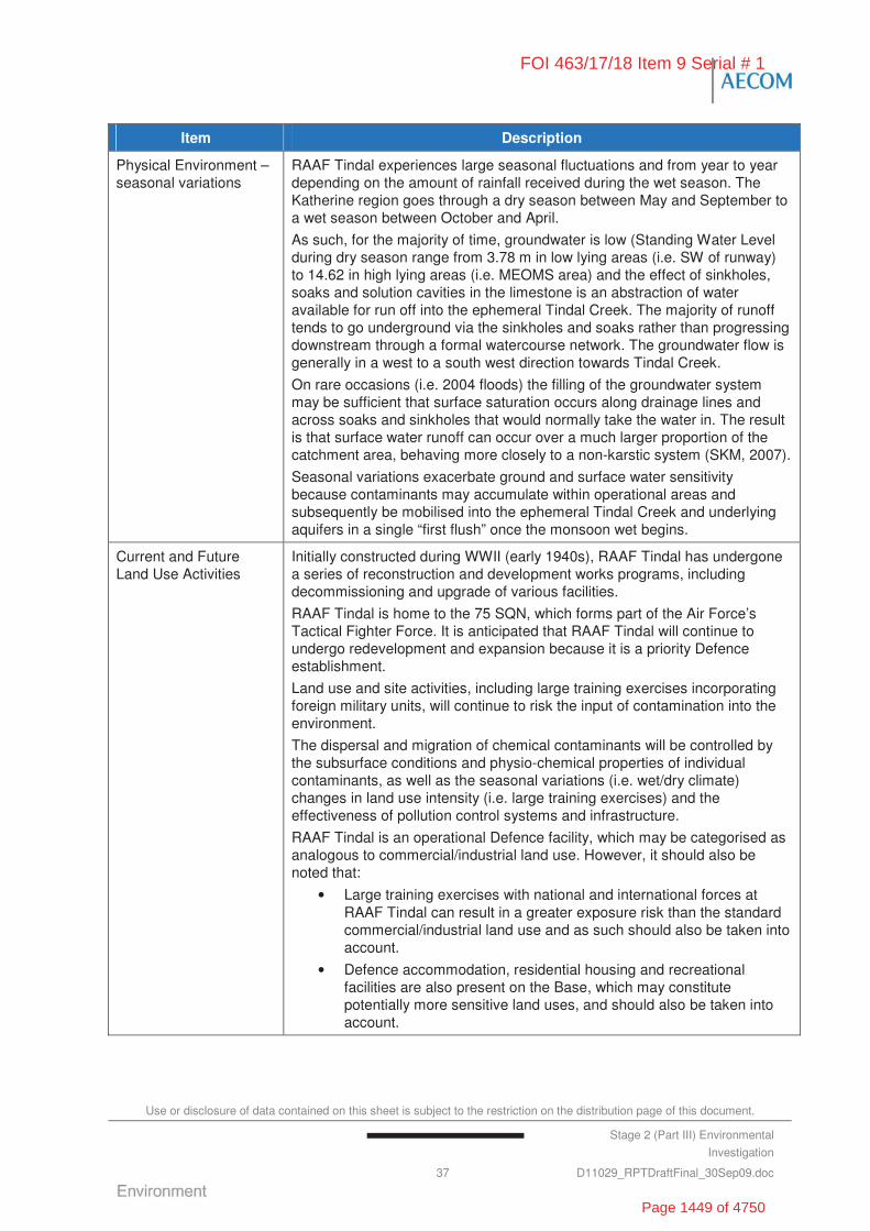
Use or disclosure of data contained on this sheet is subject to the restriction on the distribution page of this document.
Stage 2 (Part III) Environmental
Investigation
37 D11029_RPTDraftFinal_30Sep09.doc
Item Description
Physical Environment – seasonal variations
RAAF Tindal experiences large seasonal fluctuations and from year to year depending on the amount of rainfall received during the wet season. The Katherine region goes through a dry season between May and September to a wet season between October and April.
As such, for the majority of time, groundwater is low (Standing Water Level during dry season range from 3.78 m in low lying areas (i.e. SW of runway) to 14.62 in high lying areas (i.e. MEOMS area) and the effect of sinkholes, soaks and solution cavities in the limestone is an abstraction of water available for run off into the ephemeral Tindal Creek. The majority of runoff tends to go underground via the sinkholes and soaks rather than progressing downstream through a formal watercourse network. The groundwater flow is generally in a west to a south west direction towards Tindal Creek.
On rare occasions (i.e. 2004 floods) the filling of the groundwater system may be sufficient that surface saturation occurs along drainage lines and across soaks and sinkholes that would normally take the water in. The result is that surface water runoff can occur over a much larger proportion of the catchment area, behaving more closely to a non-karstic system (SKM, 2007).
Seasonal variations exacerbate ground and surface water sensitivity because contaminants may accumulate within operational areas and subsequently be mobilised into the ephemeral Tindal Creek and underlying aquifers in a single “first flush” once the monsoon wet begins.
Current and Future Land Use Activities
Initially constructed during WWII (early 1940s), RAAF Tindal has undergone a series of reconstruction and development works programs, including decommissioning and upgrade of various facilities.
RAAF Tindal is home to the 75 SQN, which forms part of the Air Force’s Tactical Fighter Force. It is anticipated that RAAF Tindal will continue to undergo redevelopment and expansion because it is a priority Defence establishment.
Land use and site activities, including large training exercises incorporating foreign military units, will continue to risk the input of contamination into the environment.
The dispersal and migration of chemical contaminants will be controlled by the subsurface conditions and physio-chemical properties of individual contaminants, as well as the seasonal variations (i.e. wet/dry climate) changes in land use intensity (i.e. large training exercises) and the effectiveness of pollution control systems and infrastructure.
RAAF Tindal is an operational Defence facility, which may be categorised as analogous to commercial/industrial land use. However, it should also be noted that:
• Large training exercises with national and international forces at RAAF Tindal can result in a greater exposure risk than the standard commercial/industrial land use and as such should also be taken into account.
• Defence accommodation, residential housing and recreational facilities are also present on the Base, which may constitute potentially more sensitive land uses, and should also be taken into account.
FOI 463/17/18 Item 9 Serial # 1
Page 1449 of 4750
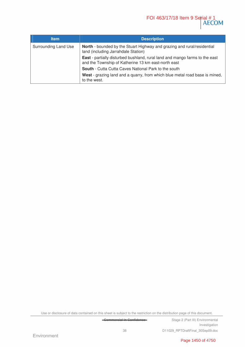
Use or disclosure of data contained on this sheet is subject to the restriction on the distribution page of this document.
Commercial in Confidence Stage 2 (Part III) Environmental
Investigation
38 D11029_RPTDraftFinal_30Sep09.doc
Item Description
Surrounding Land Use North - bounded by the Stuart Highway and grazing and rural/residential land (including Jarrahdale Station)
East - partially disturbed bushland, rural land and mango farms to the east and the Township of Katherine 13 km east-north east
South - Cutta Cutta Caves National Park to the south
West - grazing land and a quarry, from which blue metal road base is mined, to the west.
FOI 463/17/18 Item 9 Serial # 1
Page 1450 of 4750
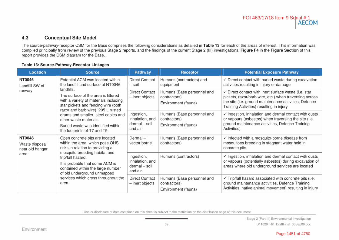
Use or disclosure of data contained on this sheet is subject to the restriction on the distribution page of this document.
Stage 2 (Part III) Environmental Investigation
39 D11029_RPTDraftFinal_30Sep09.doc
4.3 Conceptual Site Model
The source-pathway-receptor CSM for the Base comprises the following considerations as detailed in Table 13 for each of the areas of interest. This information was compiled principally from review of the previous Stage 2 reports, and the findings of the current Stage 2 (III) investigations. Figure F4 in the Figure Section of this report provides the CSM diagram for the Base.
Table 13: Source-Pathway-Receptor Linkages
Location Source Pathway Receptor Potential Exposure Pathway
Direct Contact – soil
Humans (contractors) and equipment
Direct contact with buried waste during excavation activities resulting in injury or damage
Direct Contact – inert objects
Humans (Base personnel and contractors)
Environment (fauna)
Direct contact with inert surface waste (i.e. star pickets, razor/barb wire, etc.) when traversing across the site (i.e. ground maintenance activities, Defence Training Activities) resulting in injury
NT0046
Landfill SW of runway
Potential ACM was located within the landfill and surface at NT0046 landfills.
The surface of the area is littered with a variety of materials including star pickets and fencing wire (both razor and barb wire), 205 L rusted drums and smaller, steel cables and other waste materials.
Buried waste was identified within the footprints of T7 and T9.
Ingestion, inhalation, and dermal – soil and air
Humans (Base personnel and contractors)
Environment (fauna)
Ingestion, inhalation and dermal contact with dusts or vapours (asbestos) when traversing the site (i.e. ground maintenance activities, Defence Training Activities)
Dermal – vector borne
Humans (Base personnel and contractors)
Infected with a mosquito-borne disease from mosquitoes breeding in stagnant water held in concrete pits
Ingestion, inhalation, and dermal – soil and air
Humans (contractors) Ingestion, inhalation and dermal contact with dusts or vapours (potentially asbestos) during excavation of areas where old underground services are located
NT0048
Waste disposal near old hangar area
Open concrete pits are located within the area, which pose OHS risks in relation to providing a mosquito breeding habitat and trip/fall hazard.
It is probable that some ACM is contained within the large number of old underground unmapped services which cross throughout the area.
Direct Contact – inert objects
Humans (Base personnel and contractors)
Environment (fauna)
Trip/fall hazard associated with concrete pits (i.e. ground maintenance activities, Defence Training Activities, native animal movement) resulting in injury
FOI 463/17/18 Item 9 Serial # 1
Page 1451 of 4750

Use or disclosure of data contained on this sheet is subject to the restriction on the distribution page of this document.
Commercial in Confidence Stage 2 (Part III) Environmental Investigation
40 D11029_RPTDraftFinal_30Sep09.doc
Location Source Pathway Receptor Potential Exposure Pathway
NT0049
Disposal near SAR
The area formerly comprised living quarters, a burial area and an adjacent road.
Direct Contact – inert objects
Humans (Base personnel and contractors)
Direct contact with surface waste (i.e. star pickets, razor/barb wire, potential ACM, etc.) when traversing across the site (i.e. ground maintenance activities, Defence Training Activities) resulting in injury
Direct Contact – inert objects
Humans (Base personnel and contractors)
Direct contact with surface waste (i.e. star pickets, razor/barb wire, etc.) when traversing across the site (i.e. ground maintenance activities, Defence Training Activities, site redevelopment) resulting in injury
NT0050
Waste disposal near ordnance preparation area
The area was observed to incorporate large piles of discarded cement, concrete, boulders and steel debris which was clearly visible at the ground surface and was not buried or covered.
Evidence of four discrete landfill burials comprising cement, concrete, boulders and steel debris.
Direct Contact – inert objects
Humans (contractors) Direct contact with buried waste during excavation activities resulting in injury
Direct Contact Humans (contractors) Direct contact with buried waste during excavation activities resulting in injury
Ingestion, inhalation, and dermal – soil and air
Humans (contractors) Ingestion, inhalation and dermal contact with dusts or vapours (potentially carbon fibre and AFFF) during excavation activities
NT0051
Hornet aircraft and tactical UAV burial site
Early 1990s site was used for the burial of FA/18 (~ 10 m across); and a smaller UAV (~ 4 m across). The aircraft were constructed of carbon fibre and doused in AFFF after crashing.
Both burials are well covered and the area delineated by a star picket stock fence. The site was signposted as ‘Contaminated Land’
PFOS concentrations above the laboratory LOR, but below the adopted assessment criteria was reported for Bore 25 located down hydraulic gradient of NT0051.
Ingestion, inhalation, and dermal - groundwaters
Humans (Base personnel and contractors)
Humans (Offsite)
Environment
Migration of CoPC in groundwater down hydraulic gradient with ultimate discharge into receiving abstraction bores (down hydraulic gradient) and ultimately Katherine River.
FOI 463/17/18 Item 9 Serial # 1
Page 1452 of 4750
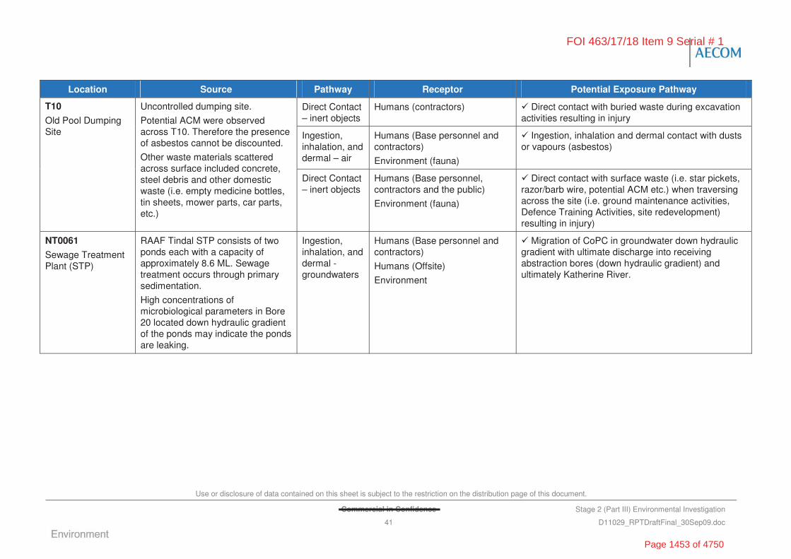
Use or disclosure of data contained on this sheet is subject to the restriction on the distribution page of this document.
Commercial in Confidence Stage 2 (Part III) Environmental Investigation
41 D11029_RPTDraftFinal_30Sep09.doc
Location Source Pathway Receptor Potential Exposure Pathway
Direct Contact – inert objects
Humans (contractors) Direct contact with buried waste during excavation activities resulting in injury
Ingestion, inhalation, and dermal – air
Humans (Base personnel and contractors)
Environment (fauna)
Ingestion, inhalation and dermal contact with dusts or vapours (asbestos)
T10
Old Pool Dumping Site
Uncontrolled dumping site.
Potential ACM were observed across T10. Therefore the presence of asbestos cannot be discounted.
Other waste materials scattered across surface included concrete, steel debris and other domestic waste (i.e. empty medicine bottles, tin sheets, mower parts, car parts, etc.)
Direct Contact – inert objects
Humans (Base personnel, contractors and the public)
Environment (fauna)
Direct contact with surface waste (i.e. star pickets, razor/barb wire, potential ACM etc.) when traversing across the site (i.e. ground maintenance activities, Defence Training Activities, site redevelopment) resulting in injury)
NT0061
Sewage Treatment Plant (STP)
RAAF Tindal STP consists of two ponds each with a capacity of approximately 8.6 ML. Sewage treatment occurs through primary sedimentation.
High concentrations of microbiological parameters in Bore 20 located down hydraulic gradient of the ponds may indicate the ponds are leaking.
Ingestion, inhalation, and dermal - groundwaters
Humans (Base personnel and contractors)
Humans (Offsite)
Environment
Migration of CoPC in groundwater down hydraulic gradient with ultimate discharge into receiving abstraction bores (down hydraulic gradient) and ultimately Katherine River.
FOI 463/17/18 Item 9 Serial # 1
Page 1453 of 4750
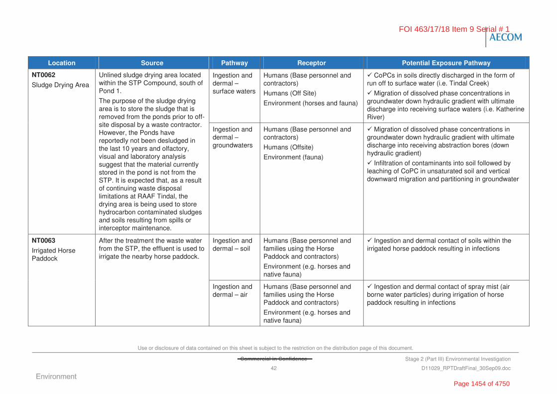
Use or disclosure of data contained on this sheet is subject to the restriction on the distribution page of this document.
Commercial in Confidence Stage 2 (Part III) Environmental Investigation
42 D11029_RPTDraftFinal_30Sep09.doc
Location Source Pathway Receptor Potential Exposure Pathway
Ingestion and dermal – surface waters
Humans (Base personnel and contractors)
Humans (Off Site)
Environment (horses and fauna)
CoPCs in soils directly discharged in the form of run off to surface water (i.e. Tindal Creek)
Migration of dissolved phase concentrations in groundwater down hydraulic gradient with ultimate discharge into receiving surface waters (i.e. Katherine River)
NT0062
Sludge Drying Area
Unlined sludge drying area located within the STP Compound, south of Pond 1.
The purpose of the sludge drying area is to store the sludge that is removed from the ponds prior to off-site disposal by a waste contractor. However, the Ponds have reportedly not been desludged in the last 10 years and olfactory, visual and laboratory analysis suggest that the material currently stored in the pond is not from the STP. It is expected that, as a result of continuing waste disposal limitations at RAAF Tindal, the drying area is being used to store hydrocarbon contaminated sludges and soils resulting from spills or interceptor maintenance.
Ingestion and dermal – groundwaters
Humans (Base personnel and contractors)
Humans (Offsite)
Environment (fauna)
Migration of dissolved phase concentrations in groundwater down hydraulic gradient with ultimate discharge into receiving abstraction bores (down hydraulic gradient)
Infiltration of contaminants into soil followed by leaching of CoPC in unsaturated soil and vertical downward migration and partitioning in groundwater
Ingestion and dermal – soil
Humans (Base personnel and families using the Horse Paddock and contractors)
Environment (e.g. horses and native fauna)
Ingestion and dermal contact of soils within the irrigated horse paddock resulting in infections
NT0063
Irrigated Horse Paddock
After the treatment the waste water from the STP, the effluent is used to irrigate the nearby horse paddock.
Ingestion and dermal – air
Humans (Base personnel and families using the Horse Paddock and contractors)
Environment (e.g. horses and native fauna)
Ingestion and dermal contact of spray mist (air borne water particles) during irrigation of horse paddock resulting in infections
FOI 463/17/18 Item 9 Serial # 1
Page 1454 of 4750

Use or disclosure of data contained on this sheet is subject to the restriction on the distribution page of this document.
Commercial in Confidence Stage 2 (Part III) Environmental Investigation
43 D11029_RPTDraftFinal_30Sep09.doc
Location Source Pathway Receptor Potential Exposure Pathway
Ingestion, inhalation and dermal – soil and dust
Humans (Base personnel and contractors) (On site)
Ingestion, inhalation and dermal contact with soil or dust during training exercises at FTA and redevelopment excavation activities
Ingestion and dermal – surface waters
Humans (Base personnel and contractors)
Humans (On/Off Site)
Environment (On/Off Site)
Ingestion and dermal contact of AFFF impacted surface water
Infiltration of surface water to groundwater impacting on higher food chain species and vulnerable flora and fauna
NT0064
Fire Training Area
AFFF, which contains PFOS/PFOA, was previously used at the FTA twice a week during training activities, although has not been used in training since 2002/2003. Replaced with the less toxic Ansulite 3%.
A 35,000 L central training pit, filled with water was present in the centre of the area which is mounded up about the surrounding areas. The pit is surrounded by concrete tile apron. It is understood that up to of 3,000 L of fuel is added to the pit during fire training exercises.
Two surface drains from the apron and the drain within the central training pit drain to a manual valve pit. The manual valve pit directs water to either three evaporation ponds (located north west of the central pit) or direct to an open surface water drain.
Three elongated concrete lined evaporation ponds are located north west of the central pit. The ponds appear to be connected by a pipe located near the top of the side wall at opposite ends of successive ponds. There is an outlet pipe from the third pond which discharges to an open surface water drain.
Ingestion and dermal – groundwaters
Humans (Base personnel and contractors)
Humans (On/Off Site)
Environment (On/Off Site)
Ingestion and dermal contact of AFFF impacted groundwater
Groundwater impact on higher food chain species and vulnerable flora and fauna
FOI 463/17/18 Item 9 Serial # 1
Page 1455 of 4750
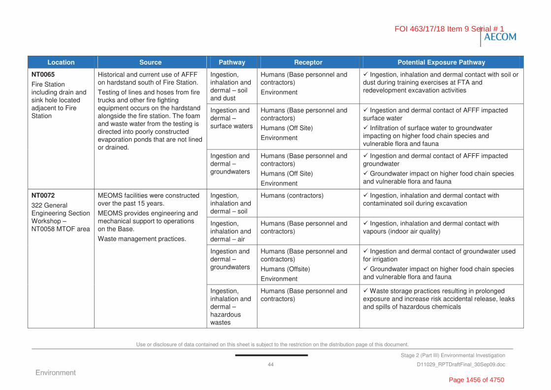
Use or disclosure of data contained on this sheet is subject to the restriction on the distribution page of this document.
Stage 2 (Part III) Environmental Investigation
44 D11029_RPTDraftFinal_30Sep09.doc
Location Source Pathway Receptor Potential Exposure Pathway
Ingestion, inhalation and dermal – soil and dust
Humans (Base personnel and contractors)
Environment
Ingestion, inhalation and dermal contact with soil or dust during training exercises at FTA and redevelopment excavation activities
Ingestion and dermal – surface waters
Humans (Base personnel and contractors)
Humans (Off Site)
Environment
Ingestion and dermal contact of AFFF impacted surface water
Infiltration of surface water to groundwater impacting on higher food chain species and vulnerable flora and fauna
NT0065
Fire Station including drain and sink hole located adjacent to Fire Station
Historical and current use of AFFF on hardstand south of Fire Station.
Testing of lines and hoses from fire trucks and other fire fighting equipment occurs on the hardstand alongside the fire station. The foam and waste water from the testing is directed into poorly constructed evaporation ponds that are not lined or drained.
Ingestion and dermal – groundwaters
Humans (Base personnel and contractors)
Humans (Off Site)
Environment
Ingestion and dermal contact of AFFF impacted groundwater
Groundwater impact on higher food chain species and vulnerable flora and fauna
Ingestion, inhalation and dermal – soil
Humans (contractors) Ingestion, inhalation and dermal contact with contaminated soil during excavation
Ingestion, inhalation and dermal – air
Humans (Base personnel and contractors)
Ingestion, inhalation and dermal contact with vapours (indoor air quality)
Ingestion and dermal – groundwaters
Humans (Base personnel and contractors)
Humans (Offsite)
Environment
Ingestion and dermal contact of groundwater used for irrigation
Groundwater impact on higher food chain species and vulnerable flora and fauna
NT0072
322 General Engineering Section Workshop – NT0058 MTOF area
MEOMS facilities were constructed over the past 15 years.
MEOMS provides engineering and mechanical support to operations on the Base.
Waste management practices.
Ingestion, inhalation and dermal – hazardous wastes
Humans (Base personnel and contractors)
Waste storage practices resulting in prolonged exposure and increase risk accidental release, leaks and spills of hazardous chemicals
FOI 463/17/18 Item 9 Serial # 1
Page 1456 of 4750
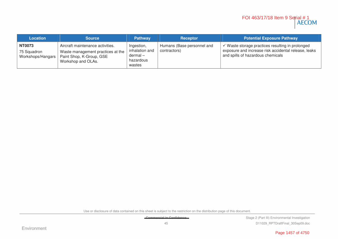
Use or disclosure of data contained on this sheet is subject to the restriction on the distribution page of this document.
Commercial in Confidence Stage 2 (Part III) Environmental Investigation
45 D11029_RPTDraftFinal_30Sep09.doc
Location Source Pathway Receptor Potential Exposure Pathway
NT0073
75 Squadron Workshops/Hangars
Aircraft maintenance activities.
Waste management practices at the Paint Shop, K-Group, GSE Workshop and OLAs.
Ingestion, inhalation and dermal – hazardous wastes
Humans (Base personnel and contractors)
Waste storage practices resulting in prolonged exposure and increase risk accidental release, leaks and spills of hazardous chemicals
FOI 463/17/18 Item 9 Serial # 1
Page 1457 of 4750
Use or disclosure of data contained on this sheet is subject to the restriction on the distribution page of this document.
Commercial in Confidence Stage 2 (Part III) Environmental Investigation
46 D11029_RPTDraftFinal_30Sep09.doc
“This page has been left blank intentionally”
FOI 463/17/18 Item 9 Serial # 1
Page 1458 of 4750
Use or disclosure of data contained on this sheet is subject to the restriction on the distribution page of this document.
Commercial in Confidence Stage 2 (Part III) Environmental
Investigation
47 D11029_RPTDraftFinal_30Sep09.doc
5.0 Site Investigation Overview
5.1 Overview
The Stage 2 (III) Investigation process followed the following general sequence:
• definition of the DQO
• underground storage tank (UST) integrity testing
• geophysical investigation of landfill areas
• test pitting and soil investigation of potentially contaminated sites and migration pathways
• groundwater quality investigation.
A brief description of the Stage 2 (III) investigation process is provided below. The investigation program was designed in consultation with the TA and the Defence Project Manager as described in detail by the SAP provided as Appendix A.
5.2 Data Quality Objectives
In designing the Stage 2 (III) environmental investigation, AECOM utilised the seven step iterative Data Quality Objectives Process developed by the United States EPA (US EPA, 2000) Guidance for the Data Quality Objectives Process (EPA QA/G-4). The application of the process to the Stage 2 (III) Investigation is described by the following sections.
5.2.1 Step 1 – State the Problem to be Resolved
The ‘problem’ for this project was to identify the real risks associated with historical activities and current operations at RAAF Tindal which may have resulted in a number of areas on site that may potentially be contaminated.
Historical activities and current operations of interest include but are not limited to: general landfill and waste disposal; aircraft and vehicle disposal (burial sites); aircraft and vehicle storage (hangars, garages); chemical, petroleum and oil storages; equipment maintenance and manufacturing facilities; paint booths and workshops; and fire training operations.
Defence commissioned this Stage 2 (III) Investigation to assess the potential for environmental and human health risks at 16 specific areas of interest, where appropriate, to develop management strategies for mitigation of these ‘real’ risks.
5.2.2 Step 2 – Identify the Decision to be Made
The decision identification component of the DQO process represents the key issues that need to be reviewed/considered in order to resolve the problem identified in Step 1. These issues include:
• Has the review of background information to evaluate the history (which in this case was largely completed by others) been adequate?
• Have primary sources of contamination been adequately characterised?
• Are contaminant concentrations at and surrounding the areas of interest above background levels?
FOI 463/17/18 Item 9 Serial # 1
Page 1459 of 4750

Use or disclosure of data contained on this sheet is subject to the restriction on the distribution page of this document.
Commercial in Confidence Stage 2 (Part III) Environmental
Investigation
48 D11029_RPTDraftFinal_30Sep09.doc
• Do the concentrations identified exceed the relevant regulatory guidelines?
• Do the contaminant concentrations adversely impact upon human health or, the environment (including phytotoxicity for the identified receptors of concern?
• Does the identified contamination have an aesthetic impact upon the environment?
• What is the proposed future use of the area and does the identified contamination affect the suitability of the site for its current or proposed use?
• Is the investigation approach scientifically suitable and defensible?
As part of the decision process, management and/or remediation strategies were also considered as part of the overall program, additional issues to be reviewed and considered included:
• What are the expectations of on-site Defence personnel and the community regarding identified contamination?
• What management techniques or remediation technologies are appropriate for the types of contamination identified at the various areas?
• What are the benefits and disadvantages of the techniques or technology? Is it proven and how readily can it be implemented, what are the cost and time implications?
• Is the nominated approach scientifically suitable and defensible?
For each area of interest, the central question to be resolved is:
• Does the investigation data and subsequent risk assessment indicate that contaminated soil or groundwater at the area of interest present an unacceptable risk level?
5.2.3 Step – 3 Indentify Inputs to the Decision
To allow assessment of the data against the objectives listed above, various inputs were considered. The following list presents various inputs that were considered:
• inspection of the site surface topography and surface materials in terms of physical evidence of contamination, potential contaminant pathways (e.g. surface water runoff, erosion, etc.)
• aesthetic impacts (odours, staining, etc.) at the surface and in samples collected at depth in test pits and boreholes
• identification of the chemicals of concern for each area, based on the assessment of the site and area specific history, anecdotal information and previous investigation data (where available)
• identification of the distribution of contamination at the sites and the depth of the contaminated material
• identification of concentrations of contaminants in soil, surface drain soil and water relative to the threshold criteria
• identification of potential on-site and off-site receptors and sensitive environments
• assessment of spatial and temporal data to adequately characterise the contamination identified at the areas of interest
• assessment of exposure pathways and exposure periods for potential receptors
FOI 463/17/18 Item 9 Serial # 1
Page 1460 of 4750
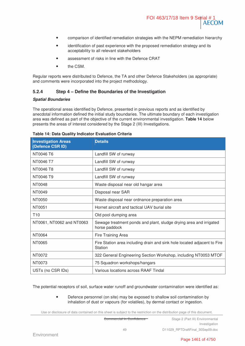
Use or disclosure of data contained on this sheet is subject to the restriction on the distribution page of this document.
Commercial in Confidence Stage 2 (Part III) Environmental
Investigation
49 D11029_RPTDraftFinal_30Sep09.doc
• comparison of identified remediation strategies with the NEPM remediation hierarchy
• identification of past experience with the proposed remediation strategy and its acceptability to all relevant stakeholders
• assessment of risks in line with the Defence CRAT
• the CSM.
Regular reports were distributed to Defence, the TA and other Defence Stakeholders (as appropriate) and comments were incorporated into the project methodology.
5.2.4 Step 4 – Define the Boundaries of the Investigation
Spatial Boundaries
The operational areas identified by Defence, presented in previous reports and as identified by anecdotal information defined the initial study boundaries. The ultimate boundary of each investigation area was defined as part of the objective of the current environmental investigation. Table 14 below presents the areas of interest considered by the Stage 2 (III) Investigations.
Table 14: Data Quality Indicator Evaluation Criteria
Investigation Areas (Defence CSR ID)
Details
NT0046 T6 Landfill SW of runway
NT0046 T7 Landfill SW of runway
NT0046 T8 Landfill SW of runway
NT0046 T9 Landfill SW of runway
NT0048 Waste disposal near old hangar area
NT0049 Disposal near SAR
NT0050 Waste disposal near ordnance preparation area
NT0051 Hornet aircraft and tactical UAV burial site
T10 Old pool dumping area
NT0061, NT0062 and NT0063 Sewage treatment ponds and plant, sludge drying area and irrigated horse paddock
NT0064 Fire Training Area
NT0065 Fire Station area including drain and sink hole located adjacent to Fire Station
NT0072 322 General Engineering Section Workshop, including NT0053 MTOF
NT0073 75 Squadron workshops/hangars
USTs (no CSR IDs) Various locations across RAAF Tindal
The potential receptors of soil, surface water runoff and groundwater contamination were identified as:
• Defence personnel (on site) may be exposed to shallow soil contamination by inhalation of dust or vapours (for volatiles), by dermal contact or ingestion.
FOI 463/17/18 Item 9 Serial # 1
Page 1461 of 4750
Use or disclosure of data contained on this sheet is subject to the restriction on the distribution page of this document.
Commercial in Confidence Stage 2 (Part III) Environmental
Investigation
50 D11029_RPTDraftFinal_30Sep09.doc
• Maintenance workers (typically contractors) may be subject to exposure from contamination of shallow soil and groundwater by ingestion, dermal contact and inhalation of volatiles.
• Other personnel will likely only be subject to exposure to contamination of groundwater by inhalation of volatiles emanating from the groundwater.
• On-site and off-site humans may also be subject to exposure to contamination from extracted groundwater and surface water by ingestion, dermal contact and inhalation of volatiles. The site is located within the Katherine Water Control District where the Township and RAAF Tindal obtain drinking water.
• On-site humans may be subject to physical hazards such as star pickets, barb wire etc. which results in injury.
• Flora and fauna (on-site) may be exposed to shallow soil and surface water contamination by inhalation of dust or vapours or by dermal contact or ingestion.
• Ecological receptors (on-site) within the underlying limestone aquifer may be exposed to groundwater contamination.
• Flora and fauna (off-site) from Tindal Creek Catchment and Katherine River may be exposed to contamination from groundwater uptake (flora) and/or entering surface water courses by ingestion, dermal contact and inhalation (fauna).
Temporal Boundaries
The time frame for the on-site investigation was a period of several weeks from 2 October 2008 to 12 November 2008.
The supplementary field investigations at NT0065 occurred in April and May 2009.
Scale of Decisions to be Made
Decisions relating to the potential human health and environmental risks associated with soil and/or groundwater contamination were assessed for each area of interest, and also in terms of the potential overall impact on the Base and surrounding areas.
Practical Constraints on Data Collection
Practical constraints on data collection were related to:
• access limitations
• the nature of the geology encountered during the intrusive investigations
• the presence of underground services
• the remote location of the areas of interest
• the delivery of samples within the recommended holding time.
5.2.5 Step 5 – Develop a Decision Rule
Based upon the relevance of all of the data collected, the decision rule for this project was to assess the need for further risk assessment, remediation or management controls in the event that the contamination encountered exceeded the relevant environmental criteria and posed a risk to Defence based upon the CRAT (Defence, 2007). This approach is consistent with the methodology outlined in
FOI 463/17/18 Item 9 Serial # 1
Page 1462 of 4750
Use or disclosure of data contained on this sheet is subject to the restriction on the distribution page of this document.
Commercial in Confidence Stage 2 (Part III) Environmental
Investigation
51 D11029_RPTDraftFinal_30Sep09.doc
the NEPM (1999) guidelines, with the exception that the approach has been modified based upon the CRAT and Defence responsibilities.
The decision rule can therefore be defined as:
if the investigation data and subsequent risk assessment indicates that contaminated soil, surface water or groundwater at the investigation area presents an unacceptable risk, further risk assessment, remediation or management controls will be implemented.
The decision rule has been used as the basis for the remediation recommendations presented in individual summaries for each area of interest.
5.2.6 Step 6 – Specify Limits on Decision Errors
A decision error in the context of the decision rule presented above would lead to either underestimation or overestimation of the risk level associated with a particular area of interest. Decision errors may include:
• limitations in the site history information available
• limitations based on inaccurate/inadequate data from current/previous investigations
• errors in the sampling plan
• data not representative of site conditions.
The issue of data representativeness was addressed via quality assurance/quality control procedures, as outlined below.
Assessment of Data Quality
Data quality was assessed by reference to the Data Quality Indicators (DQIs). The data quality assessment criteria are as follows:
• use of appropriately trained field personnel to undertake investigations
• site conditions and sample locations described properly
• field notes are appropriately completed and reviewed against measurements by laboratory analysis
• collection of representative samples from each area of interest
• samples tested for appropriate contaminants of interest
• appropriate techniques were used for sample handling (storage and transport) (refer to the SAP in Appendix A)
• use of a NATA certified laboratories using NEPM procedures
• use of a NATA certified check laboratory
• field duplicates collected at a rate of 10% with half analysed by the primary laboratory and half analysed by the check laboratory
• RPDs to be less than 30% for inorganic and 50% for organic analyses
• trip blanks collected at a rate of one sample per esky of samples submitted to the laboratory
• rinsate blanks were collected at a rate of one for every day of sampling
FOI 463/17/18 Item 9 Serial # 1
Page 1463 of 4750

Use or disclosure of data contained on this sheet is subject to the restriction on the distribution page of this document.
Commercial in Confidence Stage 2 (Part III) Environmental
Investigation
52 D11029_RPTDraftFinal_30Sep09.doc
• acceptable trip and rinsate blank analysis results
• acceptable laboratory data quality control results
• decision error within the threshold levels adopted.
5.2.7 Step 7 – Optimise the Design for Obtaining Data
The methodology presented in this report presents a sampling plan designed to: (a) meet Defence’s objectives for the Stage 2 (III) Investigation; and, (b) to achieve the nominated DQOs. Optimisation of the data collection process was achieved by:
• targeted sampling at areas of interest based upon relevant information and coordination of works in order to define the extent of potential contamination
• undertaking the investigation in a manner and to a level of accuracy and confidence as presented in NEPM documents
• review of analytical data as it is received throughout the fieldwork and completion of additional sampling, as required, to delineate the lateral and vertical extent of contamination.
5.3 Field Quality Assurance/Quality Control
All works completed as part of the Stage 2 (III) investigation at RAAF Tindal were conducted in accordance with standard AECOM environmental sampling protocols. All fieldwork was performed under the direct supervision of the AECOM Fieldwork Coordinator/Project Manager. All AECOM fieldwork personnel responsible for undertaking the fieldwork program had been trained on previous projects and were well experienced in the relevant fieldwork protocols.
The essential elements of the field QA/QC program are presented in Table 15.
Table 15: Essential Elements of the Field QA/QC Program
Action Description
Use of Experienced Personnel
Field work was completed by trained AECOM engineers/scientists with previous experience in contaminated site assessment, field sampling techniques and health and safety issues.
Record Keeping Full records of all field activities including borehole logs and sample collection were maintained on standard field logging sheets.
Sample Collection
New nitrile gloves were worn during soil sampling, and replaced between each sample collected.
All samples were collected in general accordance with AS 4482.1-2005 (Guide to the sampling and investigation of sites with potentially contaminated soil – Part 1: Non volatile and semi-volatile compounds) and AS 5667.1-1998 (Water quality – Sampling – Guidance on the design of sampling programs, sampling techniques and the preservation and handling of samples).
Sample Labelling A unique sample number was used for each sample to clearly specify the sample origin (borehole/well number and date), preservation standards and analytical requirements.
FOI 463/17/18 Item 9 Serial # 1
Page 1464 of 4750

Use or disclosure of data contained on this sheet is subject to the restriction on the distribution page of this document.
Commercial in Confidence Stage 2 (Part III) Environmental
Investigation
53 D11029_RPTDraftFinal_30Sep09.doc
Action Description
Chain of Custody
Chain of Custody procedures were required for all sample transfers. Chain of Custody sheets listed sample numbers; date of sample collection and analyses required and were signed by each person transferring and accepting custody of the samples.
Sample Storage
The collected soil and groundwater samples were transferred to approved sampling containers with appropriate preservation and then placed in cool storage prior to transfer to NATA accredited laboratories: ALS (for primary samples); LabMark (for inter-laboratory duplicate samples); Leeder (for PFOS analyses); and NTG Water Microbiological Laboratory (for microbiological analyses).
Decontamination
All equipment used in the sampling process was decontaminated using Decon 90, a phosphate free detergent, followed by rinsing with de-ionised water, prior to mobilisation and between sampling locations to reduce the risks of cross contamination. Where applicable, dedicated sampling equipment was used between each sample location and area of interest.
Intra-laboratory field duplicates
Intra-laboratory Field Duplicates refer to blind field split samples analysed by the primary laboratory. Intra-laboratory field duplicates provide information on analysis precision and sample heterogeneity. Relative percentage differences (RPDs) are used to assess precision (refer to Section 5.3.3).
Inter-laboratory field duplicates
Inter-laboratory Field Duplicates refer to blind field split samples analysed by the secondary laboratory. Inter-laboratory field duplicates provide information on analysis accuracy and sample heterogeneity, as well as the validity of the primary laboratory procedures and methodologies. RPDs are used to assess accuracy (refer to Section 5.3.3).
Trip Blanks
Trip Blank samples are an analyte free matrix to which reagents are added in the same volumes or proportions as used in standard sample preparation and analysis. Trip Blanks monitor potential cross contamination of samples within the field and storage container.
Rinsate blanks Rinsate Blank samples are analyte free water which is passed over decontaminated sampling equipment and collected in appropriate sample bottles.
5.3.1 Tank Integrity Testing QA/QC
The following steps were taken to ensure the delivery of a high quality and reliable Tank Integrity Testing program.
• Experienced consultants, JFTA, were engaged to undertake the integrity testing of 21 underground product storage tanks across RAAF Tindal.
• Integrity testing was undertaken using Alert Technologies Precision Tank Testing Systems and Acurite Line Testing Systems in accordance with:
- current manufacturers testing protocols
- AS1940-2004 The Storage and Handling of Flammable and Combustible Liquids
- AIP CP4-2002 The Design, Installation and Operation of Underground Petroleum Storage System
- US EPA regulation 40 CDR Part 280.
FOI 463/17/18 Item 9 Serial # 1
Page 1465 of 4750
Use or disclosure of data contained on this sheet is subject to the restriction on the distribution page of this document.
Commercial in Confidence Stage 2 (Part III) Environmental
Investigation
54 D11029_RPTDraftFinal_30Sep09.doc
5.3.2 Geophysical Investigation QA/QC
The following steps were taken to ensure the delivery of a high quality and reliable Electromagnetic and GPR investigation program:
• Experienced consultants and members of the Defence UXO panel, G-Tek were engaged to undertake the geophysical survey.
• Visual inspection of the area of interest while undertaking geophysical investigation
• Removal of general metallic objects and slashing of areas of interest prior to undertaking geophysical investigation.
• Documentation of the location of buried and overhanging cables and services and consideration of services when selecting the position of the survey lines.
• The instruments used were calibrated every morning, the instrument zero was continually checked during the day and battery levels were continually monitored.
• During data acquisition, individual values were compared to the surrounding values to ensure they were within the expected range.
• Differential Global Positioning System (DGPS) positions were plotted along with the data to ensure adequate data coverage in all areas.
5.3.3 Field Duplicate Samples
Field duplicate soil samples were prepared in the field by splitting the primary field sample. A groundwater field duplicate sample was collected by splitting the groundwater between the primary and field duplicate sample during sample collection. The duplicate samples were labelled so that they could not be linked to their respective primary samples. The duplicate samples and their corresponding primary sample are presented in the Appendix G.
The relative percentage difference (RPD) between primary and duplicate sample analysis results is used to measure the representativeness and/or precision of duplicate samples. The RPD is calculated from the absolute difference between results of the duplicate pair divided by the mean value of the duplicate pair.
RPD (%) = 100 x (D1-D2) / ((D1+D2) / 2)
where: D1 = primary sample analysis
D2 = duplicate sample analysis.
The AS 4482.1-2005 states that the typical RPD which can be expected from acceptable field duplicate sample is < + 30-50% of the mean concentration of the analyte where at least one result is greater than 10 times laboratory LOR. RPD values exceeding this range and criteria were considered elevated.
The duplicate sample results and RPD analysis are presented in Appendix G, Table G1 and Table G2 of this report.
5.3.3.1 Soil Analysis
A total of 176 primary soil samples were analysed by the primary laboratory. In addition, 12 intra-laboratory duplicates and seven inter-laboratory duplicates were also collected, analysed and compared with the results of the primary sample analysis.
FOI 463/17/18 Item 9 Serial # 1
Page 1466 of 4750

Use or disclosure of data contained on this sheet is subject to the restriction on the distribution page of this document.
Commercial in Confidence Stage 2 (Part III) Environmental
Investigation
55 D11029_RPTDraftFinal_30Sep09.doc
A number of other laboratories were used during the field program including Leeder (PFOS/PFOA), Australian Safer Environments and Technology (asbestos), Water Microbiological Laboratory (microbiological parameters) and Australian Radiation Services (Radium 226).
The data quality objectives, as specified in the SAP (Appendix A), required one inter-laboratory duplicate and one intra-laboratory duplicate be collected and analysed for every 20 soil samples analysed. AECOM collected duplicate samples at a frequency that was consistent with this requirement. In particular: intra-laboratory duplicates were analysed at a frequency of 1 in 14, which is compliant with QA/QC requirements; and, inter-laboratory duplicates were analysed at a frequency of 1 in 25, which is generally consistent with QA/QC requirements. As subsequent calculated RPDs complied with acceptance criteria at a high rate of 91.15% (see following discussion). This indicated that, despite field inter-laboratory duplicate collection rates of greater than 1 to 20, RPD results provided a positive indicator for sampling and analytical accuracy.
The results of the duplicate sample analysis and RPD analysis of duplicate pairs is presented in Appendix G, Table G1. Elevated RPD values were identified from a total of 226 RPD values calculated. This total excludes RPD values where both concentration values were below the laboratory LOR. Table 16 summarises the elevated RPD values obtained during the soil sampling program.
Table 16: High RPD Values during Soil Sampling Program
Duplicate Primary Sample
Inter-Lab Intra-Lab
Analyte RPD
NT0046T7TP01 (0.4 - 0.5 m) DUP05 Manganese 52%
NT0050TP08 (0.4 - 0.5 m) DUP16 Nitrite and NOx 94%
NT0050TP12 (0.4 - 0.5 m) DUP17 Nitrite and NOx 66%
NT0050TP12 (0.4 - 0.5 m) DUP18 Nitrite and NOx 102%
NT0062TP02 (0.2 - 0.3 m) DUP11
Reactive Phosphorus
73%
Nitrite 131%
Total Kjeldahl Nitrogen
130%
NT0062TP02 (0.2 - 0.3 m)
DUP12
Chromium 51%
Cadmium 100%
Manganese 155%
NT0073SED06 (0.2 - 0.3 m)
DUP19
Vanadium 111%
Manganese 141% NT0073SED06 (0.2 - 0.3 m) DUP20
Nickel 110%
T10TP02 (0.4 - 0.5 m) DUP13 Nitrite 122%
Nitrate 114%
Lead 164%
T10TP02 (0.4 - 0.5 m)
DUP14
Zinc 65%
FOI 463/17/18 Item 9 Serial # 1
Page 1467 of 4750
Use or disclosure of data contained on this sheet is subject to the restriction on the distribution page of this document.
Commercial in Confidence Stage 2 (Part III) Environmental
Investigation
56 D11029_RPTDraftFinal_30Sep09.doc
The above samples were collected either from landfill areas or drainage lines. Both landfill and drainage lines are considered disturbed areas, which may act as a collection point for a variety of materials. The frequency of RPD exceedances was not unexpected given the typical heterogeneity of landfill soil or sediment materials. It is posited that fragments of metallic waste in the sampled material may have created a ‘nugget-effect’ spike in some samples, hence leading to significant differences in metal concentrations between the primary and duplicate concentrations. Differences in nutrient levels may be attributed to natural nutrient flux, and the effects of nutrient cycling within the plant rhizosphere where material was sampled from (0 to 0.5 m below ground level (bgl)).
For all RPD values calculated, the percentage of RPDs within the acceptance criteria was 91.15% (206 RPDs within acceptance criteria from total 226 RPDs calculated). This percentage and total excludes RPD values where both concentration values were below LOR.
The results of the soil duplicate sample analysis program support the validity of the dataset and the conclusions drawn from it.
5.3.3.2 Water Analysis
Thirty-three primary water samples were collected and analysed by the primary laboratory. In addition, one intra-laboratory and one inter-laboratory duplicate sample were also collected, analysed and compared to the results of the primary sample analysis.
The data quality objectives as specified in the SAP (Appendix A) required one inter-laboratory duplicate and one intra-laboratory duplicate be collected and analysed for every 20 groundwater samples analysed. AECOM collected duplicate samples at a frequency that was consistent with this requirement. In particular, intra-laboratory duplicates and inter-laboratory duplicates were both collected at a frequency of 1 in 33. As subsequent calculated RPDs complied with acceptance criteria at a high rate of 93.75% (see following discussion). This indicated that despite field inter and intra-laboratory duplicate collection rates of greater than 1 to 20, RPD results provided a positive indicator for sampling and analytical precision accuracy.
The results of the duplicate sample analysis and subsequent RPD calculations are presented in Appendix G, Table G2. No RPD exceedances were calculated between primary and intra-laboratory duplicate groundwater results, this was a positive assessment for sample homogeneity and laboratory analytical precision.
One RPD exceedance was calculated between primary and inter-laboratory duplicate groundwater results. The RPD exceedance (RPD = 53%) was calculated between NT0073MW02 and Inter-lab duplicate DUPW02 for dissolved nickel. Groundwater from NT0073MW02 was described as having light brown to orange colouration with moderate turbidity, indicative of suspended solids present in the groundwater sample. It is possible that the high nickel concentrations are the results of isolated suspended solids within solution which was not present in the inter-lab duplicate. All other RPD values calculated with inter-laboratory duplicates were reported within acceptance criteria; this was a largely positive assessment for sample homogeneity and laboratory analytical accuracy.
For all RPD values calculated, the percentage of RPDs within the acceptance criteria was 93.75% (15 RPDs were within acceptance criteria from 16 RPDs calculated). This percentage and total excludes RPD values were both concentration values were below LOR.
The results of the water duplicate sample analysis program support the validity of the dataset and the conclusions drawn from it.
5.3.4 Rinsate Blanks
Rinsate blanks were collected to demonstrate that cross contamination did not occur as a result of sample collection practices. For the soil sampling campaign, rinsate blanks were collected at the end of
FOI 463/17/18 Item 9 Serial # 1
Page 1468 of 4750

Use or disclosure of data contained on this sheet is subject to the restriction on the distribution page of this document.
Commercial in Confidence Stage 2 (Part III) Environmental
Investigation
57 D11029_RPTDraftFinal_30Sep09.doc
every sampling day by passing deionised water over the head of the decontaminated hand auger. Rinsate blanks were not collected for the remainder of the soil sampling campaign (test pitting) as new nitrile gloves were used for the collection of every sample.
Typical sampling equipment used for the collection of groundwater samples included a dip meter, water quality meter and pump. Rinsate blanks were collected at the end of every sampling day by passing deionised water through the decontaminated pump.
The results of the rinsate blank sample analysis are presented in Appendix G, Table G3.
Most chemicals of concern were not detected in rinsate samples at concentrations greater than the laboratory LOR. Concentrations above the LOR were reported for single compounds in the following rinsate blank samples:
• Soil Sample QS12, specifically 5 g/L Phenol
• Groundwater Sample QW05, specifically 200 g/L TPH C15 - C28 Fraction.
With respect to these detections, it is noted that:
• All other analytes for rinsate blanks were below laboratory LOR.
• Rinsate Blank QS12 was submitted for analysis with soil samples from NT0073 and NT0065. From this batch, three primary soil samples were submitted for Phenol analysis. All three soil results indicated Phenol concentrations were below laboratory LOR, thus the decontamination procedures on the day were unlikely to have affected Phenol sample results.
• TPH C15 - C28 fraction concentrations were recorded in the last groundwater sample (064MW05) collected on the same day as which QW05 was taken. TPH C15 - C28 Fraction was not detected in the four previous groundwater samples submitted for TPH analyses on the same day. This observation suggests that decontamination procedures were inadequate on 12 November 2008.
• The absence of TPH contamination in the preceding four samples suggests that the decontamination deficiencies were limited to the final sample collected during that day of sampling and that an over estimation of actual concentrations did not occur. Further, the concentrations of TPH reported were less than the adopted assessment criteria and therefore have not impacted the outcomes of the investigation.
In all other instances concentrations of analytes in rinsate blank samples were reported at concentrations below the laboratory LOR indicating that decontamination procedures were otherwise adequate.
The results of the rinsate blank sample analysis support the validity of the dataset and the conclusions drawn from it.
5.3.5 Trip Blanks
Trip blanks were collected to demonstrate that samples had not been contaminated during sampling handling and transportation. A trip blank accompanied all batches of soil and groundwater samples to the laboratory.
The results of the trip blank sample analysis are presented in Appendix G, Table G3.
All trip blank results were reported at concentrations below the laboratory LOR indicating that cross contamination of samples during transit was unlikely to have occurred.
FOI 463/17/18 Item 9 Serial # 1
Page 1469 of 4750
Use or disclosure of data contained on this sheet is subject to the restriction on the distribution page of this document.
Commercial in Confidence Stage 2 (Part III) Environmental
Investigation
58 D11029_RPTDraftFinal_30Sep09.doc
The results of the trip blank sample analysis support the validity of the dataset and the conclusions drawn from it.
5.3.6 Air Sampling Field Blanks
Air sampling field blanks were analysed to demonstrate that air monitoring samples had not been contaminated during transportation or between samples. A field blank was included with every air monitoring event.
The results of the air field blank analysis are presented in Appendix G, Table G4.
All field blank results were reported at concentrations below the laboratory limit of reporting indicating that cross contamination of samples was unlikely to have occurred.
The results of the air sampling field blank analysis support the validity of the dataset and the conclusions drawn from it.
5.3.7 Sample Handling
This section provides a summary of sample handling practices and anomalies identified during the Stage 2 (III) field program.
Sample Container Integrity
No sample containers were broken or lost during transit, with the exception of one batch of microbiological samples which were sent to the NTG Water Microbiological Laboratory in Darwin using Australian Air Express (AAE). AAE did not deliver the samples to the laboratory. Where timing permitted, samples were collected again during Stage 3 site visit on 13 December 2008.
All samples were received by the laboratories with sufficient sample volume for the requested analysis.
Sample Container Selection
Sample container non-compliances were recorded for the following analyses in the following batches:
• Microbiological parameters, 18 of 18 soil samples from batch EM0809190
- This non-compliance resulted from the collection of soil samples into standard washed glass soil jars rather than the prescribed sterile plastic containers. Though noted as non-compliance, the laboratory reported that the risk of microbiological contamination from the glass jars was likely to be low.
- As a consequence, sample results for microbiological parameters in this case were considered to be reliable.
• Ferrous Iron, 3 of 3 groundwater samples from batch EM0810835
- This non-compliance resulted from the failure to field filter samples prior to placement within the laboratory prescribed clear plastic HCl preserved bottle.
- As a consequence of this non-compliance, ferrous iron analysis results from this batch are considered to be indicative only as likely overstated.
• Ammonia, 1 of 14 groundwater samples from batch EM0809748 (MW25)
- This non-compliance resulted from the collection of a sample in an un-preserved clear plastic bottle rather than the laboratory prescribed clear plastic H2SO4 preserved bottle.
FOI 463/17/18 Item 9 Serial # 1
Page 1470 of 4750

Use or disclosure of data contained on this sheet is subject to the restriction on the distribution page of this document.
Commercial in Confidence Stage 2 (Part III) Environmental
Investigation
59 D11029_RPTDraftFinal_30Sep09.doc
- As a consequence of this non-compliance, ammonia analysis results from Bore 25 are considered to be indicative only.
Sample Holding Time
Sample holding time exceedances occurred as a result of:
• unavoidable delays in sample shipment from site to the laboratory
• avoidable delays in sample shipment from site to the laboratory
• internal laboratory delays.
Holding time exceedances resulting from avoidable delays in sample shipment typically resulted from the failure of the sub-contracted courier companies to deliver the samples within the contracted timeframe. Holding times for short holding time compounds (ferrous iron, nitrate, NOx, and microbiological parameters) resulted from unavoidable delays in sample shipment from the site to the laboratory. That is, it was not physically possible for samples to be transported from the Base to the analytical laboratories.
Where holding time exceedences were not a result of shipment delays, the laboratory indicated that they had experienced significant overload which resulted in holding time failures for some batches. The laboratory stated that when overload occurred, work was prioritised to ensure holding time breaches had a minimal effect on data quality.
The majority of holding time breaches were for soil samples awaiting determination of moisture content. The laboratory offered the following justification for giving priority to other analyses:
The recommended holding time of 7 days for moisture content determination is very conservative (the technical holding time for volatile organic compounds is 14 days). Moisture content is used to report results on a dry-weight basis. Soil jars are maintained in our cool room at < 6ºC, with their lids firmly screwed on. The likelihood of loss of moisture content is insignificant. A loss/gain of moisture content of 5% would decrease/increase metal results by the same amount i.e. 5%.
Other analyses for which the holding time was exceeded are described below:
• Microbiological parameters in soil – 16 of 16 samples from NT0061 (STP) and NT0062 (Sludge Drying Area) exceeded analysis holding times by 10 days, as a result of delays once samples were delivered to the laboratory. As a consequence, the sample results were considered to be suitable for reference only.
• Nitrite in groundwater – 9 of 17 samples exceeded analysis holding times by between one and five days. Nitrite will oxidise to nitrate in the presence of oxygen or oxidising agents and this is the reason for the short holding time. As a result, the total nitrogen level (that is the total of Nitrite and Nitrate (NOx) species) remains unchanged. Samples were transported to the lab frozen and held chilled until analysis. Freezing the samples greatly reduces the rate of oxidation by limiting the chemical availability of oxidisers.
• Ferrous Iron in groundwater – 7 of 7 samples exceeded analysis holding times by one day. As a consequence, sample results were thus considered to be suitable for reference only.
• NOx in groundwater – 1 of 13 samples exceeded sample analysis holding time by three days. As a consequence, sample results were thus considered to be suitable for reference only.
FOI 463/17/18 Item 9 Serial # 1
Page 1471 of 4750

Use or disclosure of data contained on this sheet is subject to the restriction on the distribution page of this document.
Commercial in Confidence Stage 2 (Part III) Environmental
Investigation
60 D11029_RPTDraftFinal_30Sep09.doc
• Ammonia in groundwater – 1 of 21 samples exceeded analysis holding time by five days. As a consequence, sample results were thus considered to be suitable for reference only.
• Explosives in groundwater – 1 of 1 sample exceeded analysis holding time by one day. As there were no exceedances and samples were stored appropriately, the likelihood of impact on overall data quality is considered low.
• Semi Volatile Organic Compounds (SVOCs) in water - 1 rinsate sample (QS13) exceeded analysis holding time by four days. The likelihood of impact on data quality is considered low as the analytes of interest were relatively stable semi volatile compounds and samples were stored in a cool room while awaiting extraction.
5.3.8 Photo-ionisation Detector Screening
A Photoionisation Detector (PID) was used throughout the investigation to screen samples for VOCs.
Soil samples were selected for analysis based on PID screening results coupled with visual and olfactory evidence from field observations.
Field measurements generally correlated with visual and olfactory observations within the soil samples.
5.3.9 Precision and Accuracy Overall, the precision and accuracy of the laboratory analysis data was satisfactory. The two key laboratories used in the investigations (ALS and LabMark) are NATA accredited for the analyses performed.
Laboratory LOR were satisfactory for all analyses with the exception of few instances where reporting limits were raised due to matrix interferences such as excess salinity, or insufficient volumes of sample submitted.
Raised LORs were applied to results from the following batches:
• EM0809499: all water samples analysed for Ammonia, Oxides of Nitrogen, and Total Phosphorus reported raised LORs due to matrix interferences. One water sample (POND 1(Sludge)) analysed for SVOC reported raised LOR due to matrix interferences.
• EM0808937: three soil samples NT0051TP01(0-0.5), NT0051TP05(0-0.5), NT0051TP03(0-0.5) analysed for Nitrite and Oxides of Nitrogen reported raised LORs due to matrix interferences.
• EM0809499: all groundwater, surface water and sludge samples analysed for Ammonia, Oxides of Nitrogen and Total Phosphorus reported raised LORs due to matrix interferences.
• EM0809591 and EM0809649: all groundwater samples analysed for Total Kjeldahl Nitrogen, reported raised LORs due to matrix interferences.
• EM0809748: one groundwater sample (MW20) analysed for SVOCs, reported raised LOR due to insufficient sample provided for analysis.
• EM-809435: sediment and water samples analysed for SVOCs reported raised LORs due to insufficient sample provided for analysis.
FOI 463/17/18 Item 9 Serial # 1
Page 1472 of 4750
Use or disclosure of data contained on this sheet is subject to the restriction on the distribution page of this document.
Commercial in Confidence Stage 2 (Part III) Environmental
Investigation
61 D11029_RPTDraftFinal_30Sep09.doc
5.4 Laboratory Quality Assurance and Control Procedures
The principal laboratories used in the investigations (ALS and LabMark) are National Association of Testing Authorities (NATA) accredited for the analyses required. Quality assurance procedures adopted by the analytical laboratories included analysis of blanks, duplicates, laboratory control samples, matrix spikes and surrogate spikes (for organics).
A summary of the laboratory’s quality assurance procedures is presented in Table 17.
Table 17: Description of Laboratory Quality Assurance Procedures
QA Procedure Description
Laboratory Blanks and Controls
Laboratory and control blanks are analysed to test for the possibility of contamination within the laboratory. Blanks contain no analytes to undergo analysis and controls contain known reference amounts of analytes. They are generally performed at a frequency of 1 in 20.
Laboratory Duplicates A laboratory duplicate is a split sample. Duplicates provide information on the precision of the laboratory analysis methods and accuracy. RPDs are used to assess precision.
Matrix Spikes
Matrix spikes are prepared from a groundwater or soil sample with known concentrations of specific analytes for inorganic compound analysis. The samples undergo the same extraction and analysis procedures and the results are used to assess the method precision and bias. Spike recoveries are reported as a percent recovery. They are generally performed at a frequency of 1 in 20 samples.
Surrogate Spikes
Surrogate spikes are similar to matrix spikes but used for organic compound analysis. Samples are spiked with a compound similar in composition and behaviour to the target analyte but not naturally occurring in the sample. Spike recoveries are reported as a percent recovery. They are generally performed at a frequency of 1 in 20.
5.4.1 Monitoring Campaign
The monitoring campaign undertaken during the Stage 2 (III) field investigation included air monitoring samples, soil samples, groundwater samples and waste water samples submitted between 16 October to 15 December 2008 for analysis. A summary the laboratory QA/QC program is provided in Table 18 below.
Table 18: Summary Count of Results
Air Monitoring Soil Sampling Water Sampling
Matrix Type Air Soil Water Sludge Water*
First Sample Date 2/11/2008 16/10/2008 16/10/2008 6/11/2008 5/11/2008
Last Sample Date 7/11/2008 31/10/2008 30/10/2008 6/11/2008 15/12/2008
Sampling Period (days) 6 16 15 1 41
Number of Samples Submitted 30 194 10 1 49
Number of Non QA Samples Submitted 24 175 0 1 33
FOI 463/17/18 Item 9 Serial # 1
Page 1473 of 4750
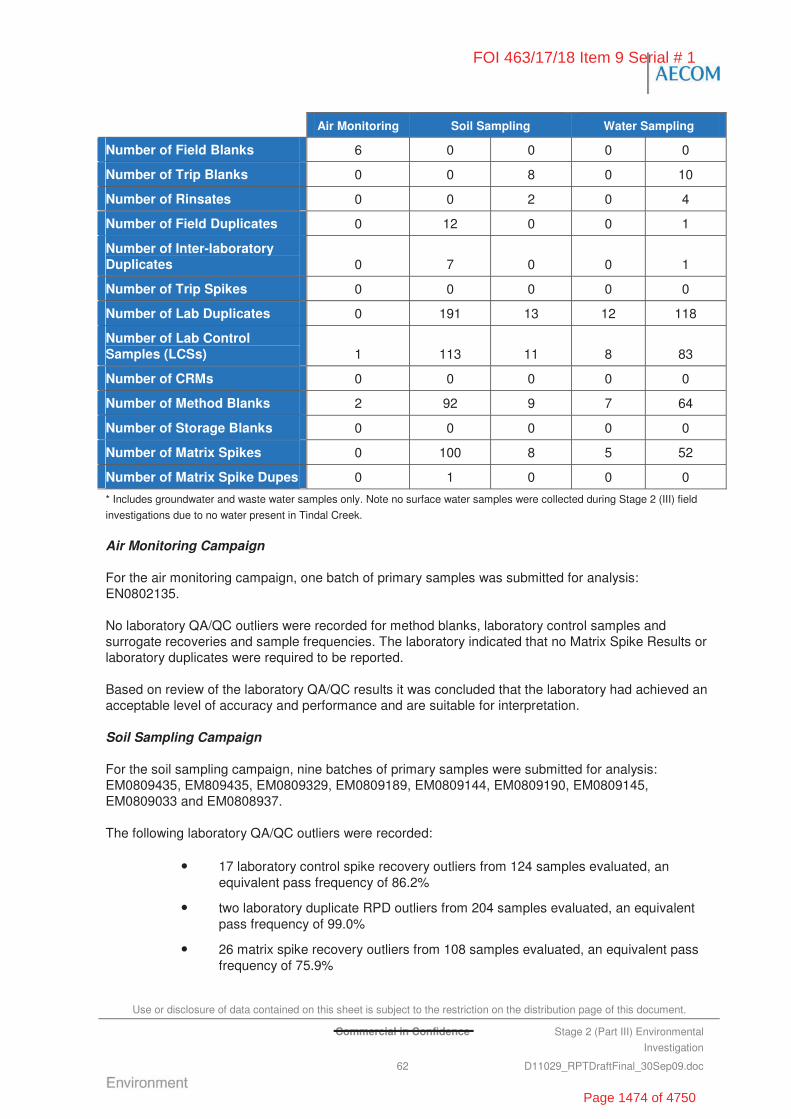
Use or disclosure of data contained on this sheet is subject to the restriction on the distribution page of this document.
Commercial in Confidence Stage 2 (Part III) Environmental
Investigation
62 D11029_RPTDraftFinal_30Sep09.doc
Air Monitoring Soil Sampling Water Sampling
Number of Field Blanks 6 0 0 0 0
Number of Trip Blanks 0 0 8 0 10
Number of Rinsates 0 0 2 0 4
Number of Field Duplicates 0 12 0 0 1
Number of Inter-laboratory Duplicates 0 7 0 0 1
Number of Trip Spikes 0 0 0 0 0
Number of Lab Duplicates 0 191 13 12 118
Number of Lab Control Samples (LCSs) 1 113 11 8 83
Number of CRMs 0 0 0 0 0
Number of Method Blanks 2 92 9 7 64
Number of Storage Blanks 0 0 0 0 0
Number of Matrix Spikes 0 100 8 5 52
Number of Matrix Spike Dupes 0 1 0 0 0
* Includes groundwater and waste water samples only. Note no surface water samples were collected during Stage 2 (III) field
investigations due to no water present in Tindal Creek.
Air Monitoring Campaign
For the air monitoring campaign, one batch of primary samples was submitted for analysis: EN0802135.
No laboratory QA/QC outliers were recorded for method blanks, laboratory control samples and surrogate recoveries and sample frequencies. The laboratory indicated that no Matrix Spike Results or laboratory duplicates were required to be reported.
Based on review of the laboratory QA/QC results it was concluded that the laboratory had achieved an acceptable level of accuracy and performance and are suitable for interpretation.
Soil Sampling Campaign
For the soil sampling campaign, nine batches of primary samples were submitted for analysis: EM0809435, EM809435, EM0809329, EM0809189, EM0809144, EM0809190, EM0809145, EM0809033 and EM0808937.
The following laboratory QA/QC outliers were recorded:
• 17 laboratory control spike recovery outliers from 124 samples evaluated, an equivalent pass frequency of 86.2%
• two laboratory duplicate RPD outliers from 204 samples evaluated, an equivalent pass frequency of 99.0%
• 26 matrix spike recovery outliers from 108 samples evaluated, an equivalent pass frequency of 75.9%
FOI 463/17/18 Item 9 Serial # 1
Page 1474 of 4750
Use or disclosure of data contained on this sheet is subject to the restriction on the distribution page of this document.
Commercial in Confidence Stage 2 (Part III) Environmental
Investigation
63 D11029_RPTDraftFinal_30Sep09.doc
• 19 sample surrogate outliers from 348 samples evaluated, an equivalent pass frequency of 94.5%.
No method blank or laboratory blank outliers were recorded. No failures to meet the required frequency of QC samples were recorded.
Based on review of the laboratory QA/QC results it was concluded that the laboratory had achieved an acceptable level of accuracy and performance and are suitable for interpretation.
Groundwater and Waste Water Sampling Campaign
For the groundwater and waste water sampling campaign, six batches of primary samples submitted for analysis: EM0810835, EM0809748, EM0809649, EM0809591, EM0809499 and EM0809511. These batches also include some soil samples consisting of sludge material from the STP.
The following laboratory QA/QC outliers were recorded:
• one laboratory duplicate RPD outlier from 130 analyte pairs evaluated, an equivalent pass frequency of 99.2 %
• six lab control spike recovery outliers from 91 samples evaluated, an equivalent pass frequency of 93.4%
• eight matrix spike recovery outliers from 57 samples evaluated, an equivalent pass frequency of 85.9%
• five sample surrogate outliers from 269 samples evaluated, an equivalent pass frequency of 98.1%
• no method Blank or lab blank outliers
• no failures to meet the required frequency of QC samples.
Based on review of the laboratory QA/QC results it was concluded that the laboratory had achieved an acceptable level of accuracy and performance and are suitable for interpretation.
5.5 QA/QC Data Assessment for Supplementary Investigation at NT0065 Fire Station
5.5.1 Supplementary Field QA/QC
All work completed during the supplementary investigation at NT0064 Fire Station were conducted in accordance with standard AECOM environmental sampling protocols as described in Table 15.
The collected soil and groundwater samples were transferred into approved sampling containers with appropriate preservation as required and then placed in cool storage prior to transfer to laboratories that were NATA accredited for the specific requested analysis (LabMark, ALS, MGT, Leeder).
In addition to the primary samples, quality control field duplicate samples were collected to assess aspects of field protocols and laboratory performance and to classify the validity of the laboratory data. Field duplicates were collected in general accordance with AS 4482.1-2005 Guide to the Investigation and Sampling of Sites with Potentially Contaminated Soil (Standards Australia 2005).
5.5.2 Field Duplicates
Field intra-duplicate / inter-duplicate groundwater samples were prepared in the field by equally splitting the primary field samples. The duplicate samples were labelled so that they could not be linked to their
FOI 463/17/18 Item 9 Serial # 1
Page 1475 of 4750

Use or disclosure of data contained on this sheet is subject to the restriction on the distribution page of this document.
Commercial in Confidence Stage 2 (Part III) Environmental
Investigation
64 D11029_RPTDraftFinal_30Sep09.doc
respective primary samples. The duplicate samples analysed and their corresponding primary samples are detailed in Table 19, below.
Table 19: Field Duplicate Samples
Primary Sample ID Matrix Intra Laboratory Duplicate Sample
Inter Laboratory Duplicate Sample
Date
NT0065TP10/0.1 m Soil QC1 QC2 09/04/2009
NT0065TP01/0.5 m Soil QC3 QC4 09/04/2009
NT0065MW01 Groundwater QA/QC01 - 14/05/2009
5.5.3 Supplementary Soil Investigation
NT0065 supplementary soil investigation required primary and intra-laboratory duplicate samples to be sent to LabMark (Melbourne) for analysis of chemicals of potential concern, and Leeder (Melbourne) for analysis of perfluorochemical compounds.
Inter-laboratory duplicate samples were sent to MGT (Melbourne) for analysis of chemicals of potential concern, and CRC Care (University of South Australia) for analysis of perfluorochemical compounds.
An additional two primary soil samples from NT0062 Sludge Drying Area were submitted to ALS (Melbourne) for analysis on the 14 April 2009. This was to confirm field observations of a stronger odour and more material dumped at the Sludge Drying Area since the October 2009 field investigation.
The duplicate sample results and RPD analysis are presented Appendix G, Table G5.
For the soil samples, a total of two RPD values were calculated, where the result was greater than ten times the laboratory LOR, and greater than the typical RPD. This represented a failure of two RPD samples from a total 74 RPDs calculated, and a high RPD pass frequency of 97%.
The exceedances involved the analysis anionic surfactant as MBAS between the primary and intra-laboratory duplicate sample, and primary and inter-laboratory duplicate sample. It was noted that MBAS limits of reporting for all the inter-laboratory duplicate samples were significantly raised due to sample matrix inteferences, and this has resulted in a conservatively high RPD.
5.5.4 Supplementary Groundwater Investigation
NT0065 supplementary groundwater investigation required two primary and one intra-laboratory duplicate sample to be sent to ALS (Melbourne) for analysis of chemicals of potential concern, and Leeder (Melbourne) for analysis of perfluorochemical compounds.
The duplicate sample results and RPD analysis are presented in Appendix G, Table G5.
5.5.5 Supplementary Laboratory QA/QC
The laboratories used in the investigations (Labmark, ALS and Leeder) are National Association of Testing Authorities (NATA) approved for the analyses required. CRC Care was used for comparative analysis of perfluorochemicals in soil and for this reason, their results are considered to be indicative only. Quality assurance procedures adopted by the key analytical laboratories included analysis of blanks, duplicates, laboratory control samples, matrix spikes and surrogate spikes (for organics).
The laboratory reported that all samples were received in appropriately pre-treated and preserved containers, and received in adequate holding times.
FOI 463/17/18 Item 9 Serial # 1
Page 1476 of 4750
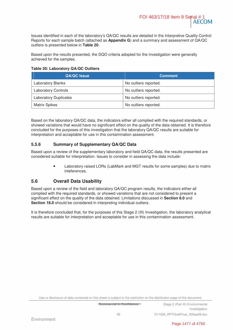
Use or disclosure of data contained on this sheet is subject to the restriction on the distribution page of this document.
Commercial in Confidence Stage 2 (Part III) Environmental
Investigation
65 D11029_RPTDraftFinal_30Sep09.doc
Issues identified in each of the laboratory’s QA/QC results are detailed in the Interpretive Quality Control Reports for each sample batch (attached as Appendix G) and a summary and assessment of QA/QC outliers is presented below in Table 20.
Based upon the results presented, the DQO criteria adopted for the investigation were generally achieved for the samples.
Table 20: Laboratory QA/QC Outliers
QA/QC Issue Comment
Laboratory Blanks No outliers reported.
Laboratory Controls No outliers reported.
Laboratory Duplicates No outliers reported.
Matrix Spikes No outliers reported.
Based on the laboratory QA/QC data, the indicators either all complied with the required standards, or showed variations that would have no significant effect on the quality of the data obtained. It is therefore concluded for the purposes of this investigation that the laboratory QA/QC results are suitable for interpretation and acceptable for use in this contamination assessment.
5.5.6 Summary of Supplementary QA/QC Data
Based upon a review of the supplementary laboratory and field QA/QC data, the results presented are considered suitable for interpretation. Issues to consider in assessing the data include:
• Laboratory raised LORs (LabMark and MGT results for some samples) due to matrix inteferences.
5.6 Overall Data Usability
Based upon a review of the field and laboratory QA/QC program results, the indicators either all complied with the required standards, or showed variations that are not considered to present a significant effect on the quality of the data obtained. Limitations discussed in Section 8.0 and Section 18.0 should be considered in interpreting individual outliers.
It is therefore concluded that, for the purposes of this Stage 2 (III) Investigation, the laboratory analytical results are suitable for interpretation and acceptable for use in this contamination assessment.
FOI 463/17/18 Item 9 Serial # 1
Page 1477 of 4750

Use or disclosure of data contained on this sheet is subject to the restriction on the distribution page of this document.
Commercial in Confidence Stage 2 (Part III) Environmental
Investigation
66 D11029_RPTDraftFinal_30Sep09.doc
“This page has been left blank intentionally”
FOI 463/17/18 Item 9 Serial # 1
Page 1478 of 4750

Use or disclosure of data contained on this sheet is subject to the restriction on the distribution page of this document.
Commercial in Confidence Stage 2 (Part III) Environmental
Investigation
67 D11029_RPTDraftFinal_30Sep09.doc
6.0 Soil and Water Assessment Criteria
The site is located on Commonwealth Land (in the Northern Territory) and is therefore not subject to Territory or State based legislation. AECOM understands that in the absence of specific Commonwealth Legislation it is Defence policy to comply with the spirit and intent of state and territory legislation and guidelines. Therefore, Northern Territory, other States and International environmental quality guidelines and investigation protocols have been adopted as part of the Stage 2 (III) Investigation.
The following section describes the assessment criteria adopted during the Stage 2 (III) Investigation.
6.1 Soil and Sediment Acceptance Criteria
The soil acceptance criteria adopted for the Stage 2 (III) Investigation are largely based on the National Environment Protection (Assessment of Site Contamination) Measure (NEPC, 1999). These guidelines present a range of Health Investigation Levels (HILs) and Ecological Investigation Levels (EILs).
It should be noted that the guidelines, currently adopted by the Northern Territory Government Department of Natural Resources, Environment, The Arts and Sport (NRETAS) Environmental Protection Agency Program (EPA), for the assessment of potential human health risks and ecological risks are based on:
• National Environment Protection (Assessment of Site Contamination) Measure (NEPC, 1999)
• Guidelines for Assessing Service Station Sites (NSW EPA, 1994).
The application of these guidelines to the Stage 2 (III) investigation and other guidelines adopted has been described below.
6.1.1 National Environment Protection Measures
NEPM Health Investigation Levels (HILs)
The HILs in the NEPM (NEPC, 1999) guidelines are based on the National Environmental Health Forum (NEHF) levels devised by Imray and Langley (1996). A series of guideline levels are provided for various substances for the protection of human health based on four specific land use and exposure scenarios including:
• HILA Residential with gardens and accessible soil (home-grown produce contributing less than 10% fruit and vegetable intake, but not poultry), including children’s day care centres, preschools and primary schools, or town houses or villas
• HILD Residential with minimal access to soil including high-rise apartments and flats
• HILE Parks, recreational open space, playing fields including secondary schools
• HILF Commercial and industrial.
It is noted that the NEPM HILs are not intended for use as default remediation trigger criteria, but are actually intended to prompt an appropriate site-specific assessment when they are exceeded.
FOI 463/17/18 Item 9 Serial # 1
Page 1479 of 4750
Use or disclosure of data contained on this sheet is subject to the restriction on the distribution page of this document.
Commercial in Confidence Stage 2 (Part III) Environmental
Investigation
68 D11029_RPTDraftFinal_30Sep09.doc
NEPM Interim Urban Ecological Investigation Levels (EILs)
The Interim Urban EILs in the NEPM (NEPC, 1999) have been devised for the protection of plants, and are designed to be applied as single number criteria indicative of environmental effect. Their use has significant limitations since phytotoxicity depends on soil and species parameters; therefore they are intended to be applied as a screening guide only. The decision process for assessing urban redevelopment sites stipulates that the provisional phytotoxicity based investigation levels (PBILs) need to be considered on sites used for either residential purposes, or land uses including parks, recreational open space and secondary schools.
6.1.2 NSW EPA Guidelines for Assessing Guidelines for Assessing Service Station Sites
The NEPM HILs (NEPC, 1999) include criteria for lower volatility aliphatic and aromatic petroleum hydrocarbon components for the various land use scenarios described above rather than the general fractions commonly referred to. Therefore, for the assessment of petroleum hydrocarbon contamination in soil, the NSW EPA (1998) guidelines refer to the use of the Guidelines for Assessing Service Station Sites (NSW EPA, 1994). These guidelines contain threshold concentrations for contaminants in soil which are designed to provide for the protection of human and environmental health assuming a sensitive land use.
HILs specifically for the lower volatility aliphatic and aromatic petroleum hydrocarbon components are provided in NEPC (1999) for the various land use scenarios described in that document.
6.1.3 Minnesota Department of Health Guideline for PFOS/PFOA
AFFF refers to a range of proprietary mixtures used in the fighting of fires, and therefore its exact composition varies between suppliers. However, historically, the key constituents from a toxicity perspective are diethylene glycol butyl ether (DGBE), perfluoro-octane sulfonate (PFOS) and perfluoro-octanoic acid (PFOA).
DGBE has historically been the primary constituent of most AFFF mixtures and is classified by the USEPA as a suspected carcinogen. Although it is possible to analyse specifically for DGBE, the compound is known to degrade rapidly in the environment. As such, the analysis of PFOS/PFOA was thus considered more appropriate in consideration of the DGBE’s rapid degradation potential.
PFOS is considered to present the highest risk to human health and the environment because it is both toxic (classified as a carcinogen by the USEPA) and persistent in the environment. While research to date has shown no direct evidence that compounds such as PFOS cause health problems in humans, studies in laboratory animals indicate that at higher doses, perfluorochemicals (PFCs) may interfere with liver and thyroid function and may cause developmental effects (MDH, 2007). The toxicity of PFOS is related to the presence of fluorooctanoic salts, which are not present in any of the anionic surfactants for which ANZECC provides a criterion.
The RAAF Tindal combined Stage 1 & 2 (I) Investigation (ERM, 2007a) and the Stage 2 (II) Investigation (GHD, 2008) adopted an initial screening criterion of 40 mg/kg for PFOS in Industrial Soils and 20 mg/kg in Residential Soils. This was based on a guideline published by the MDH (2005) as part of a suite of soil reference values (SRVs), developed as part of a health consultation process study into environmental release of PFCs.
These soil reference values have been revised by the MDH (2007) to:
• Residential Land Use – PFOA (2 mg/kg), PFOS (2 mg/kg)
• Industrial Land Use – PFOA (13 mg/kg), PFOS (14 mg/kg).
FOI 463/17/18 Item 9 Serial # 1
Page 1480 of 4750

Use or disclosure of data contained on this sheet is subject to the restriction on the distribution page of this document.
Commercial in Confidence Stage 2 (Part III) Environmental
Investigation
69 D11029_RPTDraftFinal_30Sep09.doc
In the absence of any other national guidelines, the Stage 2 (III) Investigation has adopted the MDH (2007) Industrial Land use guideline as a screening criterion.
6.1.4 Other Guidelines
For chemicals of concern at the Base where there is no current Australian guideline, AECOM has adopted the following guidelines.
• US EPA Regional Screening Levels (RSLs) for Chemical Contaminants at Superfund Sites – Explosives compounds were assessed against the RSLs for Chemical Contaminants in Industrial Soils published by the US EPA (US EPA, 2009). Exceedances of the guideline values may have toxicity implications to human health and warrant further investigation. It should be noted that the US EPA Region 9 Preliminary Remediation Goals (PRG) have been harmonised with similar risk-based screening levels used by Regions 3 and 6 into a single table: Regional Screening Levels (RSL) for Chemical Contaminants at Superfund Sites (April 2009).
• UNSCEAR (2000) – Radium 226 levels in soil were assessed against the UNSCEAR (2000) sources and effects of ionising radiation global median value for average natural radionuclides in soil.
• WA Department of Health (2009) - Soil investigation criteria threshold for asbestos as ACM in Commercial/Industrial Soils.
6.1.5 Adopted Site Assessment Criteria for Soil and Sediment
Based on the current land use continuing at RAAF Tindal, soil sample analysis results were compared against the NEPM HILF and EIL guidelines as summarised in Table 21. Where the NEPM does not contain guideline values for the required contaminants of concern, alternative guidelines have been adopted as described above and summarised by Table 21, including the NSW EPA (1994) guidelines screening criteria for hydrocarbons.
Sediment samples collected from the open unlined surface water drainage system at RAAF Tindal were assessed using the NEPM EILs. These guidelines were considered the most applicable because they reflect a terrestrial ecosystem. Other available sediment specific guidelines (e.g. ANZECC 2000 interim sediment quality objectives) relate to aquatic systems, where benthos in sediment fauna requires consideration.
A predominately targeted sampling program, focussed on specific areas of interest was adopted for the investigation. Therefore, the statistical method of comparing analytical result to the NEPM HILs and EILs (as recommended by NEPM) was not considered appropriate and individual results were compared directly against the guideline values.
Table 21: Soil Acceptance Criteria
Analyte NEPM HILF Criteriaa NEPM EIL Criteriad Additional Criteria
Inorganics
Arsenic 500 20 -
Barium - 300 -
Beryllium 100 - -
Cadmium 100 3 -
Chromium (III) e 60% 400 -
Cobalt 500 - -
FOI 463/17/18 Item 9 Serial # 1
Page 1481 of 4750
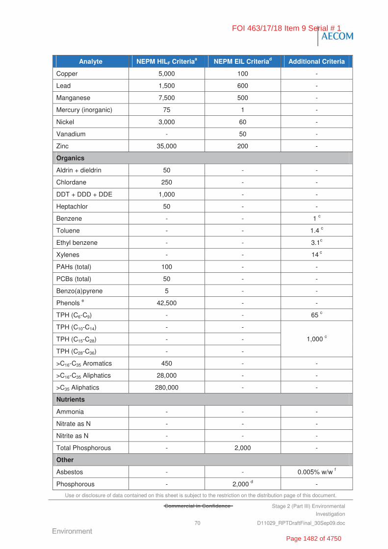
Use or disclosure of data contained on this sheet is subject to the restriction on the distribution page of this document.
Commercial in Confidence Stage 2 (Part III) Environmental
Investigation
70 D11029_RPTDraftFinal_30Sep09.doc
Analyte NEPM HILF Criteriaa NEPM EIL Criteriad Additional Criteria
Copper 5,000 100 -
Lead 1,500 600 -
Manganese 7,500 500 -
Mercury (inorganic) 75 1 -
Nickel 3,000 60 -
Vanadium - 50 -
Zinc 35,000 200 -
Organics
Aldrin + dieldrin 50 - -
Chlordane 250 - -
DDT + DDD + DDE 1,000 - -
Heptachlor 50 - -
Benzene - - 1 c
Toluene - - 1.4 c
Ethyl benzene - - 3.1c
Xylenes - - 14 c
PAHs (total) 100 - -
PCBs (total) 50 - -
Benzo(a)pyrene 5 - -
Phenols e 42,500 - -
TPH (C6-C9) - - 65 c
TPH (C10-C14) - -
TPH (C15-C28) - -
TPH (C28-C36) - -
1,000 c
>C16-C35 Aromatics 450 - -
>C16-C35 Aliphatics 28,000 - -
>C35 Aliphatics 280,000 - -
Nutrients
Ammonia - - -
Nitrate as N - - -
Nitrite as N - - -
Total Phosphorous - 2,000 -
Other
Asbestos - - 0.005% w/w f
Phosphorous - 2,000 d -
FOI 463/17/18 Item 9 Serial # 1
Page 1482 of 4750
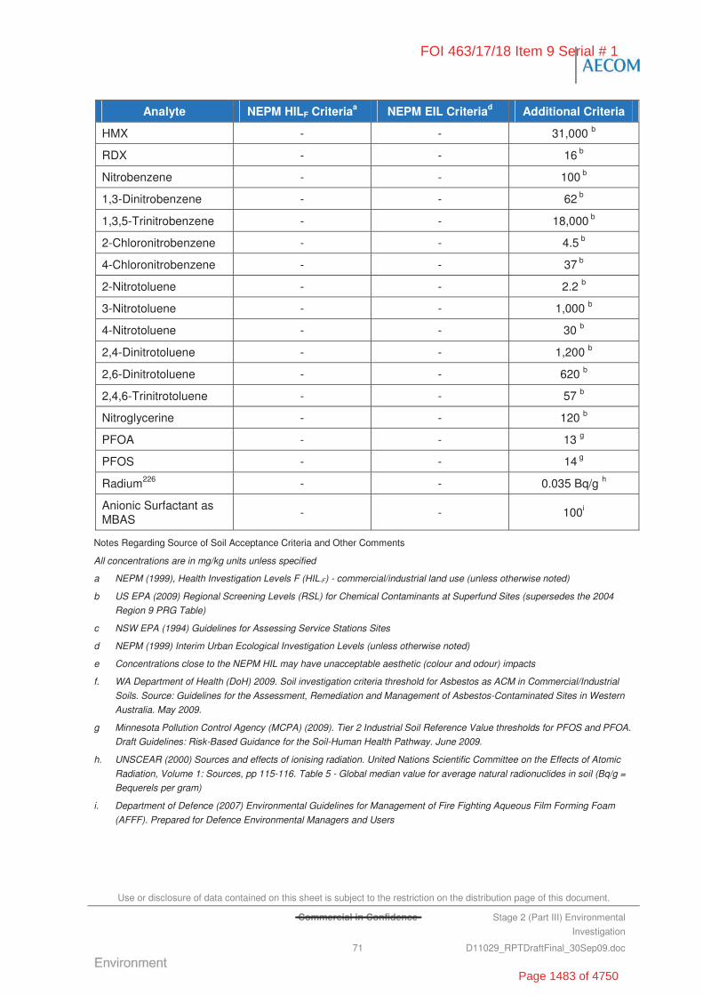
Use or disclosure of data contained on this sheet is subject to the restriction on the distribution page of this document.
Commercial in Confidence Stage 2 (Part III) Environmental
Investigation
71 D11029_RPTDraftFinal_30Sep09.doc
Analyte NEPM HILF Criteriaa NEPM EIL Criteriad Additional Criteria
HMX - - 31,000 b
RDX - - 16 b
Nitrobenzene - - 100 b
1,3-Dinitrobenzene - - 62 b
1,3,5-Trinitrobenzene - - 18,000 b
2-Chloronitrobenzene - - 4.5 b
4-Chloronitrobenzene - - 37 b
2-Nitrotoluene - - 2.2 b
3-Nitrotoluene - - 1,000 b
4-Nitrotoluene - - 30 b
2,4-Dinitrotoluene - - 1,200 b
2,6-Dinitrotoluene - - 620 b
2,4,6-Trinitrotoluene - - 57 b
Nitroglycerine - - 120 b
PFOA - - 13 g
PFOS - - 14 g
Radium226 - - 0.035 Bq/g h
Anionic Surfactant as MBAS
- - 100i
Notes Regarding Source of Soil Acceptance Criteria and Other Comments
All concentrations are in mg/kg units unless specified
a NEPM (1999), Health Investigation Levels F (HIL-F) - commercial/industrial land use (unless otherwise noted)
b US EPA (2009) Regional Screening Levels (RSL) for Chemical Contaminants at Superfund Sites (supersedes the 2004
Region 9 PRG Table)
c NSW EPA (1994) Guidelines for Assessing Service Stations Sites
d NEPM (1999) Interim Urban Ecological Investigation Levels (unless otherwise noted)
e Concentrations close to the NEPM HIL may have unacceptable aesthetic (colour and odour) impacts
f. WA Department of Health (DoH) 2009. Soil investigation criteria threshold for Asbestos as ACM in Commercial/Industrial
Soils. Source: Guidelines for the Assessment, Remediation and Management of Asbestos-Contaminated Sites in Western
Australia. May 2009.
g Minnesota Pollution Control Agency (MCPA) (2009). Tier 2 Industrial Soil Reference Value thresholds for PFOS and PFOA.
Draft Guidelines: Risk-Based Guidance for the Soil-Human Health Pathway. June 2009.
h. UNSCEAR (2000) Sources and effects of ionising radiation. United Nations Scientific Committee on the Effects of Atomic
Radiation, Volume 1: Sources, pp 115-116. Table 5 - Global median value for average natural radionuclides in soil (Bq/g =
Bequerels per gram)
i. Department of Defence (2007) Environmental Guidelines for Management of Fire Fighting Aqueous Film Forming Foam
(AFFF). Prepared for Defence Environmental Managers and Users
FOI 463/17/18 Item 9 Serial # 1
Page 1483 of 4750
Use or disclosure of data contained on this sheet is subject to the restriction on the distribution page of this document.
Stage 2 (Part III) Environmental
Investigation
72 D11029_RPTDraftFinal_30Sep09.doc
6.2 Surface and Groundwater Acceptance Criteria
The surface water and groundwater acceptance criteria adopted for the Stage 2 (III) Investigation are largely based on the ANZECC guidelines for Freshwater and Marine Water Quality (ANZECC, 2000). These guidelines are adopted by the Northern Territory Government Department of Natural Resources, Environment, The Arts and Sport (NRETAS) Environmental Protection Agency Program (EPA), for the assessment of potential human health risks and ecological risks.
The application of these guidelines to the Stage 2 (III) Investigation and other guidelines adopted has been described below.
6.2.1 ANZECC Guidelines for Fresh and Marine Water Quality
The surface water and groundwater acceptance criteria adopted for the Stage 2 (III) Investigation have been largely based on the ANZECC (2000) Guidelines for Fresh and Marine Water Quality. ANZECC (2000) guidelines supersede the 1992 ANZECC guidelines and the NEPM Groundwater Investigation Levels (GILs) which are based on them. The ANZECC 2000 Water Quality Guidelines, where available, are considered the most appropriate for this assessment.
The ANZECC 2000 guidelines provide a range of trigger values, expressed in terms of the percentage of known species that are expected to be protected by the nominated value. The appropriate trigger value for a given site should be selected based on the degree to which current and past practices have resulted in disturbance of the receiving water body and if contaminants bioaccumulate in the environment. In particular:
• The 99% protection trigger values are recommended for receiving waters of high conservation/ecological value or contaminants bioaccumulate in the environment. Such receiving waters are effectively unmodified or other highly-valued ecosystems, typically (but not always) occurring in national parks or conservation reserves or in remote or inaccessible locations.
• The 95% protection trigger values are recommended for receiving waters that have been slightly to moderately disturbed. Such receiving waters may have been adversely affected to a relatively small, but measurable degree, but continue to maintain the integrity of the ecosystem.
• The 90% protection trigger values are recommended for highly disturbed ecosystems. Such receiving waters are measurably degraded aquatic ecosystems of lower ecological value.
6.2.2 Australian Drinking Water Guidelines
The 2004 Australian Drinking Water Guidelines (ADWG) have been developed by the National Health and Medical Research Council (NHMRC) in collaboration with the Natural Resource Management Ministerial Council (NRMMC). The ADWG incorporates the Framework for the Management of Drinking Water Quality and provides the Australian community and the water supply industry with guidance on what constitutes good quality drinking water.
RAAF Tindal falls within the Katherine Water Control District which is largely made up of the unconfined section of the Tindall Limestone Aquifer and is clearly demarcated within the Daly River Catchment Aquifer Formation. The Katherine Township obtains its drinking water from the Katherine River and supplements the water supply with groundwater from extraction bore fields. RAAF Tindal’s potable water is supplied by the Katherine Township, and onsite extraction bores utilise groundwater resources directly from the Tindall Limestone for irrigation purposes (AECOM, 2009a).
FOI 463/17/18 Item 9 Serial # 1
Page 1484 of 4750
Use or disclosure of data contained on this sheet is subject to the restriction on the distribution page of this document.
Commercial in Confidence Stage 2 (Part III) Environmental
Investigation
73 D11029_RPTDraftFinal_30Sep09.doc
As such, given that background groundwater quality at the site may be considered suitable for a range of extractive uses, including human consumption, the groundwater results have been compared to the ADWG, 2004.
6.2.3 Netherlands Ministry of Housing Dutch Intervention Value for TPH
In the absence of high reliability TPH trigger value in the ANZECC guidelines, TPH results were assessed against the Netherlands Ministry of Housing Intervention Value for light hydrocarbon fraction (TPH Fraction C6-C9 of 100 g/L) and mineral oil fraction (TPH Fraction C10-C36 of 600 g/L) (NMH, 2000) (Dutch Intervention Levels (DIL)) for screening criteria for groundwater impacts.
It is acknowledged that the ANZECC guidelines do reference a low reliability criteria (7 g/L) derived by Tsvetnenko (1998). This potential criterion is based on an assessment factor (AF) of 100, and it is noted that if the AF were not applied, the resultant guideline would be similar to the DIL. Notwithstanding, the low reliability criterion referenced by ANZECC was considered too conservative in this application because: (a) it is not specific to a particular TPH fraction range; (b) it makes no distinction between aromatic and aliphatic TPHs; and (c) it is based on a worst case pollution scenario such as a constant discharge to the environment at a rate that exceeds the losses from evaporation or dispersion (Tsvetnenko, 1998). In addition, laboratories can not quantify results to such low concentrations.
6.2.4 Minnesota Department of Health, Health Risk Limit for PFOS/PFOA
The RAAF Tindal Stage 2 (II) Investigation (GHD, 2008) adopted initial screening criteria for PFOS and PFOA in groundwater of 0.3 μg/L and 0.5 μg/L, respectively. This was based on a guideline developed by the MDH (2007) as a health based value (HBV) to protect residents from long-term exposure to PFCs in groundwater. It is understood that these values were largely based on laboratory limits of reporting and not specific risk based considerations.
Since the Stage 2 (II) Investigations, MDH (2009) have reviewed the assessment criteria for health risk limits (HRL) in drinking water for PFOS and PFOA. The revised HRLs are 0.3 μg/L for both PFOS and PFOA.
In addition, the United States Environmental Protection Agency (US EPA) has set short-term provisional health advisory values for PFOA and PFOS of 0.4 μg/L and 0.2 μg/L, respectively. These values were issued in response to EPA Region 4’s request for assistance after finding elevated levels of PFOA and PFOS in sewage sludge in Alabama (US EPA, 2009).
As such, in the absence of other national guidelines, the Stage 2 (III) Investigation will refer to both the MDH (2009) and US EPA (2009) health based values as a screening criterion.
6.2.5 Adopted Site Assessment Criteria for Groundwater and Surface Water
Given the dynamic and disturbed nature of the receiving waters (namely the ephemeral Tindal Creek), the 95% level of species protection has been adopted for the investigation (where laboratory techniques can be quantified to these limits). The 99% species protection criteria has been used for chemicals that bioaccumulate (e.g. Organochlorine Pesticides (OC) and some heavy metals including mercury) where applicable.
The ANZECC (2000) guidelines present three levels of criteria: high reliability; moderate reliability and low reliability. The low reliability values were derived using broad assessment factors to account for uncertainty in the absence of a data set of sufficient quality. High reliability values were adopted where available. Low reliability values were used where high reliability values were not available.
In some instances, the limits of reporting achieved by the analytical laboratories were above the ANZECC (2000) freshwater 95% protection criteria. In these instances, the laboratory LOR and
FOI 463/17/18 Item 9 Serial # 1
Page 1485 of 4750

Use or disclosure of data contained on this sheet is subject to the restriction on the distribution page of this document.
Commercial in Confidence Stage 2 (Part III) Environmental
Investigation
74 D11029_RPTDraftFinal_30Sep09.doc
background concentrations (where available) were adopted as a guide for identifying the presence or absence of a contaminant.
Surface water and groundwater acceptance criteria adopted for the Stage 2 (III) Investigation are summarised in Table 22, below.
Table 22: Surface Water and Groundwater Acceptance Criteria
Analyte ANZECC Trigger Value for Freshwater Aquatic Ecosystems at 95%
protection levela
Australian Drinking Water Guidelines
Health / Aestheticb
Metals/Metalloids
Arsenic 13* 7
Cadmium 0.2 2
Chromium (III) 3.3* -
Chromium (VI) 1 50**
Copper 1.4 2,000 / 1,000
Lead 3.4 10
Mercury (inorganic) 0.06 e 1
Nickel 11 20
Zinc 8 3,000
Volatile Organics Compounds (VOCs)
1;1;1-Trichloroethane 270 d -
1;1;2;2-Tetrachloroethane 400 d -
1;1;2-Trichloroethane 6,500 -
1;1-Dichloroethene 700 d 30
1;2;3-Trichlorobenzene 10 -
1;2;4-Trichlorobenzene 85 e -
1;2-Dichlorobenzene 160 1,500 / 1
1;2-Dichloropropane 900 d -
1;2-Dichloroethane 1,900 d 3
1;3-Dichlorobenzene 260 20
1;3-Dichloropropane 1,100 d -
1;4-Dichlorobenzene 60 40 / 3
Benzene 950 1
Toluene 180 d -
Carbon Tetrachloride 240 d 3
Chlorobenzene 55 d 300 / 10
Chloroform 370 d -
FOI 463/17/18 Item 9 Serial # 1
Page 1486 of 4750
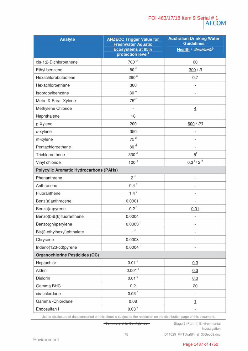
Use or disclosure of data contained on this sheet is subject to the restriction on the distribution page of this document.
Commercial in Confidence Stage 2 (Part III) Environmental
Investigation
75 D11029_RPTDraftFinal_30Sep09.doc
Analyte ANZECC Trigger Value for Freshwater Aquatic Ecosystems at 95%
protection levela
Australian Drinking Water Guidelines
Health / Aestheticb
cis-1;2-Dichloroethene 700 d^ 60
Ethyl benzene 80 d 300 / 3
Hexachlorobutadiene 290 e 0.7
Hexachloroethane 360 -
Isopropylbenzene 30 e -
Meta- & Para- Xylene 75c* -
Methylene Chloride - 4
Naphthalene 16
p-Xylene 200 600 / 20
o-xylene 350 -
m-xylene 75 d -
Pentachloroethane 80 d -
Trichloroethene 330 d 5f
Vinyl chloride 100 c 0.3 i / 2 h
Polycylic Aromatic Hydrocarbons (PAHs)
Phenanthrene 2 d -
Anthracene 0.4 d -
Fluoranthene 1.4 d -
Benz(a)anthracene 0.0001 i -
Benzo(a)pyrene 0.2 d 0.01
Benzo(b)&(k)fluoranthene 0.0004 i -
Benzo(ghi)perylene 0.0003 i -
Bis(2-ethylhexyl)phthalate 1 d -
Chrysene 0.0003 i -
Indeno(123-cd)pyrene 0.0004 i -
Organochlorine Pesticides (OC)
Heptachlor 0.01 e 0.3
Aldrin 0.001 d 0.3
Dieldrin 0.01 d 0.3
Gamma BHC 0.2 20
cis-chlordane 0.03 e -
Gamma -Chlordane 0.08 1
Endosulfan I 0.03 e -
FOI 463/17/18 Item 9 Serial # 1
Page 1487 of 4750

Use or disclosure of data contained on this sheet is subject to the restriction on the distribution page of this document.
Commercial in Confidence Stage 2 (Part III) Environmental
Investigation
76 D11029_RPTDraftFinal_30Sep09.doc
Analyte ANZECC Trigger Value for Freshwater Aquatic Ecosystems at 95%
protection levela
Australian Drinking Water Guidelines
Health / Aestheticb
4,4-DDE 0.03 d -
4,4-DDT 0.01 20 (total DDT)
Endrin 0.01 e -
Endosulfan II 0.007 d -
Methoxychlor 0.005 d 300
Organophosphorus Pesticides (OP)
Demeton (total) 0.04 d -
Dimethoate 0.15 -
Diazinon 0.01 3
Ethion - 3
Fenitrothion 0.2 10
Malathion 0.05 50
Chlorpyrifos 0.01 10
Chlorofevinphos - 5
Parathion 0.004 10
Ronnel 30
Azinophos methyl 0.01 e -
Phenol
Pentachlorophenol 3.6 e 10
Phenol 320 -
2-chlorophenol 340 e 300
2-nitrophenol 2 d -
2,4-dimethylphenol 2 d -
2,4-dichlorophenol 120 e 200
2,4,6-trichlorophenol 3 e 20
2,4,5-trichlorophenol 0.5 d -
Total Petroleum Hydrocarbons
TPH Fraction C6-C9 65 j -
TPH Fraction C10-C36 600 j -
Nitrated Compounds (Explosives)
Nitrobenzene 550 d -
1,3-Dinitrobenzene 13 d -
1,3,5-Trinitrobenzene 4 d -
FOI 463/17/18 Item 9 Serial # 1
Page 1488 of 4750

Use or disclosure of data contained on this sheet is subject to the restriction on the distribution page of this document.
Commercial in Confidence Stage 2 (Part III) Environmental
Investigation
77 D11029_RPTDraftFinal_30Sep09.doc
Analyte ANZECC Trigger Value for Freshwater Aquatic Ecosystems at 95%
protection levela
Australian Drinking Water Guidelines
Health / Aestheticb
2-Nitrotoluene 110 d -
3-Nitrotoluene 75 d -
4-Nitrotoluene 120 d -
2,4-Dinitrotoluene 16 -
2,4,6-Trinitrotoluene 140 -
Other Compounds
PFOS 0.3 k / 0.2 l -
PFOA 0.3 k / 0.4 l -
Faecal Coliforms (CFU/100 mL) 1,000 f -
Nutrients
Ammonia 900 (at pH=8) 0.5
Nitrate as N 0.7 50
Nitrite as N - -
Total Nitrogen as N 150L -
Total Phosphorus as P 10L -
Reactive Phosphorus as P 5L -
Physical and Chemical Stressors
Dissolved Oxygen (% saturation) <80 - >110 g -
pH (pH units) 6 - 8 g -
Total Nitrogen 200 g -
NOx (Nitrate + Nitrite) 5 g -
Total Phosphorus 10 g -
Notes mg/L unless otherwise noted.
a. ANZECC 2000 Guidelines: ANZECC/ARMCANZ 2000. The Australian and New Zealand Guidelines for Fresh and Marine
Water Quality. Australian and New Zealand Environment and Conservation Council, Agriculture and Resource
Management Council of Australia and New Zealand
b. Australian Drinking Water Guidelines: National Health and Medical Research Council 2004. Australian Drinking Water
Guidelines. National Water Quality Management Strategy publication.
c. Dutch Groundwater intervention values. Source - VROM 2008 Soil Remediation Circular 2006, as amended on 1 October
2008. Ministerie van Volkshuisvesting, Ruimtelijke Ordening en Milieubeheer/Netherlands Ministry of Housing, Spatial
Development and Environment
d. ANZECC 2000 Freshwater Low Reliability Trigger Values, (due to insufficient data), to be used only as an indicative interim
working level only
d^ Lower reliability level for 1,1 dichloroethene
d* ANZECC low reliability trigger value for p-xylene, used as a conservative threshold to compare against total m- & p-xylene
laboratory results.
FOI 463/17/18 Item 9 Serial # 1
Page 1489 of 4750
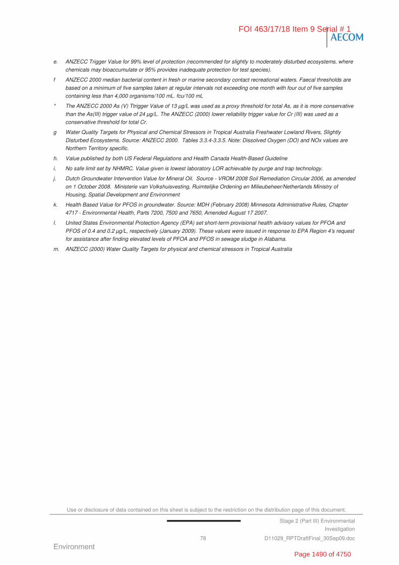
Use or disclosure of data contained on this sheet is subject to the restriction on the distribution page of this document.
Stage 2 (Part III) Environmental
Investigation
78 D11029_RPTDraftFinal_30Sep09.doc
e. ANZECC Trigger Value for 99% level of protection (recommended for slightly to moderately disturbed ecosystems, where
chemicals may bioaccumulate or 95% provides inadequate protection for test species).
f ANZECC 2000 median bacterial content in fresh or marine secondary contact recreational waters. Faecal thresholds are
based on a minimum of five samples taken at regular intervals not exceeding one month with four out of five samples
containing less than 4,000 organisms/100 mL. fcu/100 mL
* The ANZECC 2000 As (V) Ttrigger Value of 13 μg/L was used as a proxy threshold for total As, as it is more conservative
than the As(III) trigger value of 24 μg/L. The ANZECC (2000) lower reliability trigger value for Cr (III) was used as a
conservative threshold for total Cr.
g Water Quality Targets for Physical and Chemical Stressors in Tropical Australia Freshwater Lowland Rivers, Slightly
Disturbed Ecosystems. Source: ANZECC 2000. Tables 3.3.4-3.3.5. Note: Dissolved Oxygen (DO) and NOx values are
Northern Territory specific.
h. Value published by both US Federal Regulations and Health Canada Health-Based Guideline
i. No safe limit set by NHMRC. Value given is lowest laboratory LOR achievable by purge and trap technology.
j. Dutch Groundwater Intervention Value for Mineral Oil. Source - VROM 2008 Soil Remediation Circular 2006, as amended
on 1 October 2008. Ministerie van Volkshuisvesting, Ruimtelijke Ordening en Milieubeheer/Netherlands Ministry of
Housing, Spatial Development and Environment
k. Health Based Value for PFOS in groundwater. Source: MDH (February 2008) Minnesota Administrative Rules, Chapter
4717 - Environmental Health, Parts 7200, 7500 and 7650, Amended August 17 2007.
l. United States Environmental Protection Agency (EPA) set short-term provisional health advisory values for PFOA and
PFOS of 0.4 and 0.2 μg/L, respectively (January 2009). These values were issued in response to EPA Region 4’s request
for assistance after finding elevated levels of PFOA and PFOS in sewage sludge in Alabama.
m. ANZECC (2000) Water Quality Targets for physical and chemical stressors in Tropical Australia
FOI 463/17/18 Item 9 Serial # 1
Page 1490 of 4750
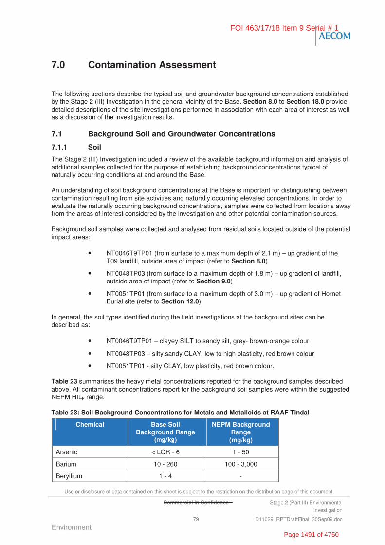
Use or disclosure of data contained on this sheet is subject to the restriction on the distribution page of this document.
Commercial in Confidence Stage 2 (Part III) Environmental
Investigation
79 D11029_RPTDraftFinal_30Sep09.doc
7.0 Contamination Assessment
The following sections describe the typical soil and groundwater background concentrations established by the Stage 2 (III) Investigation in the general vicinity of the Base. Section 8.0 to Section 18.0 provide detailed descriptions of the site investigations performed in association with each area of interest as well as a discussion of the investigation results.
7.1 Background Soil and Groundwater Concentrations
7.1.1 Soil
The Stage 2 (III) Investigation included a review of the available background information and analysis of additional samples collected for the purpose of establishing background concentrations typical of naturally occurring conditions at and around the Base.
An understanding of soil background concentrations at the Base is important for distinguishing between contamination resulting from site activities and naturally occurring elevated concentrations. In order to evaluate the naturally occurring background concentrations, samples were collected from locations away from the areas of interest considered by the investigation and other potential contamination sources.
Background soil samples were collected and analysed from residual soils located outside of the potential impact areas:
• NT0046T9TP01 (from surface to a maximum depth of 2.1 m) – up gradient of the T09 landfill, outside area of impact (refer to Section 8.0)
• NT0048TP03 (from surface to a maximum depth of 1.8 m) – up gradient of landfill, outside area of impact (refer to Section 9.0)
• NT0051TP01 (from surface to a maximum depth of 3.0 m) – up gradient of Hornet Burial site (refer to Section 12.0).
In general, the soil types identified during the field investigations at the background sites can be described as:
• NT0046T9TP01 – clayey SILT to sandy silt, grey- brown-orange colour
• NT0048TP03 – silty sandy CLAY, low to high plasticity, red brown colour
• NT0051TP01 - silty CLAY, low plasticity, red brown colour.
Table 23 summarises the heavy metal concentrations reported for the background samples described above. All contaminant concentrations report for the background soil samples were within the suggested NEPM HILF range.
Table 23: Soil Background Concentrations for Metals and Metalloids at RAAF Tindal
Chemical Base Soil Background Range
NEPM Background Range (mg/kg)
Arsenic < LOR - 6 1 - 50
Barium 10 - 260 100 - 3,000
Beryllium 1 - 4 -
FOI 463/17/18 Item 9 Serial # 1
Page 1491 of 4750
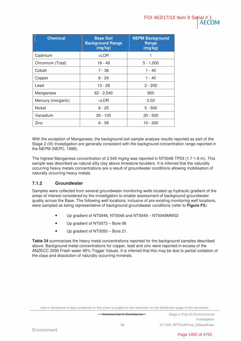
Use or disclosure of data contained on this sheet is subject to the restriction on the distribution page of this document.
Commercial in Confidence Stage 2 (Part III) Environmental
Investigation
80 D11029_RPTDraftFinal_30Sep09.doc
Chemical Base Soil Background Range
NEPM Background Range (mg/kg)
Cadmium <LOR 1
Chromium (Total) 18 - 49 5 - 1,000
Cobalt 7 - 36 1 - 40
Copper 6 - 24 1 - 40
Lead 13 - 29 2 - 200
Manganese 62 - 2,540 850
Mercury (inorganic) <LOR 0.03
Nickel 6 - 25 5 - 500
Vanadium 26 - 105 20 - 500
Zinc 6 - 59 10 - 300
With the exception of Manganese, the background soil sample analysis results reported as part of the Stage 2 (III) Investigation are generally consistent with the background concentration range reported in the NEPM (NEPC, 1999).
The highest Manganese concentration of 2,540 mg/kg was reported in NT0048 TP03 (1.7-1.8 m). This sample was described as natural silty clay above limestone boulders. It is inferred that the naturally occurring heavy metals concentrations are a result of groundwater conditions allowing mobilisation of naturally occurring heavy metals.
7.1.2 Groundwater
Samples were collected from several groundwater monitoring wells located up hydraulic gradient of the areas of interest considered by the investigation to enable assessment of background groundwater quality across the Base. The following well locations, inclusive of pre-existing monitoring well locations, were sampled as being representative of background groundwater conditions (refer to Figure F5):
• Up gradient of NT0046, NT0048 and NT0049 – NT0049MW02
• Up gradient of NT0073 – Bore 06
• Up gradient of NT0050 – Bore 21.
Table 24 summarises the heavy metal concentrations reported for the background samples described above. Background metal concentrations for copper, lead and zinc were reported in excess of the ANZECC 2000 Fresh water 95% Trigger Values. It is inferred that this may be due to partial oxidation of the clays and dissolution of naturally occurring minerals.
FOI 463/17/18 Item 9 Serial # 1
Page 1492 of 4750
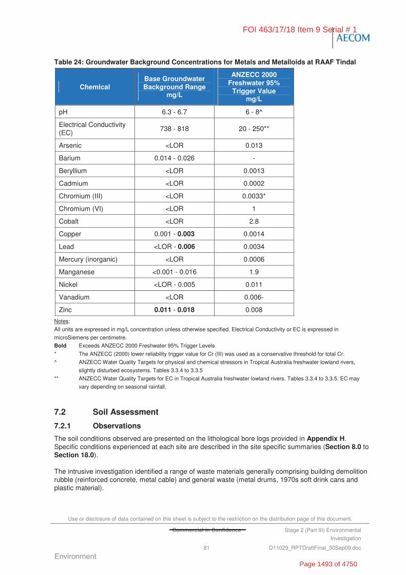
Use or disclosure of data contained on this sheet is subject to the restriction on the distribution page of this document.
Commercial in Confidence Stage 2 (Part III) Environmental
Investigation
81 D11029_RPTDraftFinal_30Sep09.doc
Table 24: Groundwater Background Concentrations for Metals and Metalloids at RAAF Tindal
Chemical Base Groundwater Background Range
g/L
ANZECC 2000 Freshwater 95%
Trigger Value g/L
pH 6.3 - 6.7 6 - 8^
Electrical Conductivity (EC)
738 - 818 20 - 250**
Arsenic <LOR 0.013
Barium 0.014 - 0.026 -
Beryllium <LOR 0.0013
Cadmium <LOR 0.0002
Chromium (III) <LOR 0.0033*
Chromium (VI) <LOR 1
Cobalt <LOR 2.8
Copper 0.001 - 0.003 0.0014
Lead <LOR - 0.006 0.0034
Mercury (inorganic) <LOR 0.0006
Manganese <0.001 - 0.016 1.9
Nickel <LOR - 0.005 0.011
Vanadium <LOR 0.006-
Zinc 0.011 - 0.018 0.008
Notes:
All units are expressed in mg/L concentration unless otherwise specified. Electrical Conductivity or EC is expressed in
microSiemens per centimetre.
Bold Exceeds ANZECC 2000 Freshwater 95% Trigger Levels
* The ANZECC (2000) lower reliability trigger value for Cr (III) was used as a conservative threshold for total Cr.
^ ANZECC Water Quality Targets for physical and chemical stressors in Tropical Australia freshwater lowland rivers,
slightly disturbed ecosystems. Tables 3.3.4 to 3.3.5
** ANZECC Water Quality Targets for EC in Tropical Australia freshwater lowland rivers. Tables 3.3.4 to 3.3.5. EC may
vary depending on seasonal rainfall.
7.2 Soil Assessment
7.2.1 Observations
The soil conditions observed are presented on the lithological bore logs provided in Appendix H. Specific conditions experienced at each site are described in the site specific summaries (Section 8.0 to Section 18.0).
The intrusive investigation identified a range of waste materials generally comprising building demolition rubble (reinforced concrete, metal cable) and general waste (metal drums, 1970s soft drink cans and plastic material).
FOI 463/17/18 Item 9 Serial # 1
Page 1493 of 4750

Use or disclosure of data contained on this sheet is subject to the restriction on the distribution page of this document.
Commercial in Confidence Stage 2 (Part III) Environmental
Investigation
82 D11029_RPTDraftFinal_30Sep09.doc
It is suspected that where fibro sheeting and old piping were identified across RAAF Tindal, that there is a potential that they contained asbestos. This is based on the age of construction of many the facilities at RAAF Tindal which were demolished.
No UXO was identified during the intrusive investigation.
7.2.2 Field PID Screening
Field screening for volatile organic compounds (VOCs) was undertaken during the soil sampling activities. VOC concentrations in soil were measured in the field using a calibrated photo-ionised detector (PID); refer to bore logs in Appendix H.
Elevated VOC concentrations were only detected at NT0062 Sludge Drying Area south of the Sewage Treatment Pond (335 parts per million (ppm)).
7.2.3 Soil Analysis Summary
The soil analysis results are presented in the Tables Section of this report. Laboratory analytical reports are presented in Appendix I.
Metals and Metalloids
A total of 172 soil samples were analysed for metals and metalloids. A statistical summary of the results is presented in Table 25.
Table 25: Summary Soil Analytical Results (Metals and metalloids)
Analyte No. of Detects
Min (mg/kg)
Max (mg/kg)
Average (mg/kg)
No. >EILs1
No. >HILF
1
Arsenic 26 5 10 6.4 0 0
Barium 132 10 690 59 6 0
Beryllium 78 1 6 1.8 0 0
Cadmium ND LOR LOR LOR 0 0
Chromium (Total) 171 6 101 31 0 0
Cobalt 162 2 78 12 0 0
Copper 155 5 61 15 0 0
Lead 160 5 132 18 0 0
Manganese 171 21 4,530 368 22 0
Mercury (inorganic) 3 0.1 0.3 0.17 0 0
Nickel 169 3 61 12 1 0
Vanadium 171 11 148 59 102 0
Zinc 130 5 334 31 2 0
Notes:
Bold concentrations exceeding soil investigation criteria published in the NEPM (1999) guidelines.
LOR Limit of Reporting
ND Not Detected
1 Number of samples exceeding the NEPM (1999) Environmental Investigation Levels (EILs) and and Health Investigation
Levels (HILs). EILs and HILs are not intended for use as default remediation trigger criteria, but are actually intended to prompt an
appropriate site-specific assessment when they are exceeded
FOI 463/17/18 Item 9 Serial # 1
Page 1494 of 4750
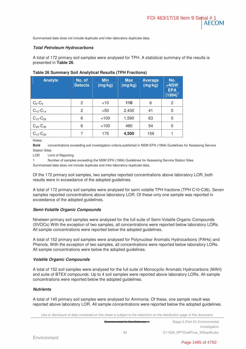
Use or disclosure of data contained on this sheet is subject to the restriction on the distribution page of this document.
Commercial in Confidence Stage 2 (Part III) Environmental
Investigation
83 D11029_RPTDraftFinal_30Sep09.doc
Summarised data does not include duplicate and inter-laboratory duplicate data.
Total Petroleum Hydrocarbons
A total of 172 primary soil samples were analysed for TPH. A statistical summary of the results is presented in Table 26.
Table 26 Summary Soil Analytical Results (TPH Fractions)
Analyte No. of Detects
Min (mg/kg)
Max (mg/kg)
Average (mg/kg)
No. >NSW EPA
(1994)1
C6-C9 2 <10 110 6 2
C10-C14 2 <50 2,430 41 0
C15-C28 6 <100 1,590 63 0
C29-C36 6 <100 480 54 0
C10-C36 7 175 4,500 159 1
Notes:
Bold concentrations exceeding soil investigation criteria published in NSW EPA (1994) Guidelines for Assessing Service
Station Sites
LOR Limit of Reporting
1 Number of samples exceeding the NSW EPA (1994) Guidelines for Assessing Service Station Sites
Summarised data does not include duplicate and inter-laboratory duplicate data.
Of the 172 primary soil samples, two samples reported concentrations above laboratory LOR, both results were in exceedance of the adopted guidelines.
A total of 172 primary soil samples were analysed for semi volatile TPH fractions (TPH C10-C36). Seven samples reported concentrations above laboratory LOR. Of these only one sample was reported in exceedance of the adopted guidelines.
Semi-Volatile Organic Compounds
Nineteen primary soil samples were analysed for the full suite of Semi-Volatile Organic Compounds (SVOCs) With the exception of two samples, all concentrations were reported below laboratory LORs. All sample concentrations were reported below the adopted guidelines.
A total of 152 primary soil samples were analysed for Polynuclear Aromatic Hydrocarbons (PAHs) and Phenols. With the exception of two samples, all concentrations were reported below laboratory LORs. All sample concentrations were below the adopted guidelines.
Volatile Organic Compounds
A total of 152 soil samples were analysed for the full suite of Monocyclic Aromatic Hydrocarbons (MAH) and suite of BTEX compounds. Up to 4 soil samples were reported above laboratory LORs. All sample concentrations were reported below the adopted guidelines.
Nutrients
A total of 145 primary soil samples were analysed for Ammonia. Of these, one sample result was reported above laboratory LOR. All sample concentrations were reported below the adopted guidelines.
FOI 463/17/18 Item 9 Serial # 1
Page 1495 of 4750
Use or disclosure of data contained on this sheet is subject to the restriction on the distribution page of this document.
Commercial in Confidence Stage 2 (Part III) Environmental
Investigation
84 D11029_RPTDraftFinal_30Sep09.doc
A total of 131 primary soil samples were analysed for Oxides of Nitrogen (Nitrate, Nitrite, Total NOx). Of the samples analysed, concentrations above the laboratory limit of reporting were recorded in 113 samples for Nitrate, 26 samples for Nitrite, and 117 samples for NOx. Sample result concentrations above LOR ranged from 0.101 mg/kg to 4,810 mg/kg for Nitrates, 0.117 mg/kg to 2.86 mg/kg for Nitrite, and 0.106 mg/kg to 4810 mg/kg of Total NOx.
A total of 17 primary soil samples were analysed for Total Nitrogen (TN) and Total Kjeldahl Nitrogen (TKN). All sample results were reported at concentrations above the laboratory LOR, ranging from 230 mg/kg to 2020 mg/kg TN, and 230 mg/kg to 2,010 mg/kg TKN.
A total of 16 primary soil samples were analysed for Total Phosphorus (TP) and Reactive Phosphorus (RP). Of the samples analysed, concentrations above the laboratory LOR were recorded in 13 samples. All sample results were reported at concentrations above the laboratory LOR, with concentrations ranging from 45 mg/kg to 368 mg/kg TP and 0.178 mg/kg to 14.6 mg/kg RP. All sample concentrations were reported below the adopted guidelines for TP.
Explosives
Twenty primary soil samples were analysed for explosives. All sample concentrations were reported at concentrations below the adopted guidelines and the laboratory LOR.
Asbestos
Twenty primary soil samples were analysed for asbestos. No detection of asbestos was reported by the analysing laboratory.
Radium-226
Fifteen primary soil samples from NT0051 (Hornet and Vehicle Burial Area) were analysed for the radioisotope Radium-226 (226Ra). All soil samples reported 226Ra at detectable levels. Of these, 226Ra levels in seven of the 15 soil samples analysed exceeded the United Nations Scientific Committee on the Effects of Atomic Radiation reference value of 0.035 Bq/g.
A detailed discussion of the Radium-226 analysis results is provided in the NT0051 (Hornet Burial Area) site summary in Section 12.0.
Pefluorochemicals
Eight primary soil samples were analysed for Perfluorochemicals including Perfluorooctanoic Acid (PFOA), Perfluorooctane sulfonate (PFOS) during October 2008 at NT0065 Fire Station area of interest. The results of the sampling program reported PFOS in all eight samples ranging from 0.035 mg/kg to 360 mg/kg. Of the eight samples, two samples NT0065HA04 (0.0 to 0.1 m) and NT0065HA04 (0.2 to 0.3 m) exceeded the MCPA (2009) Industrial Soil Reference Value thresholds of 14 mg/kg. In addition, PFOA was reported in six of the eight soil samples but were below the adopted MCPA (2009) Industrial Soil Reference Value threshold of 13 mg/kg.
Additional samples were collected for PFOS/PFOA as part of the supplementary investigations carried out at NT0065 in April 2009. The results also recorded elevated concentrations of PFOS/PFOA. A detailed discussion of the PFOS/PFOA analysis results is provided in the NT0065 (Fire Station) site summary in Section 16.0.
Note that no soil samples were collected from the FTA as part of the Stage 2 (III) Investigation program.
FOI 463/17/18 Item 9 Serial # 1
Page 1496 of 4750
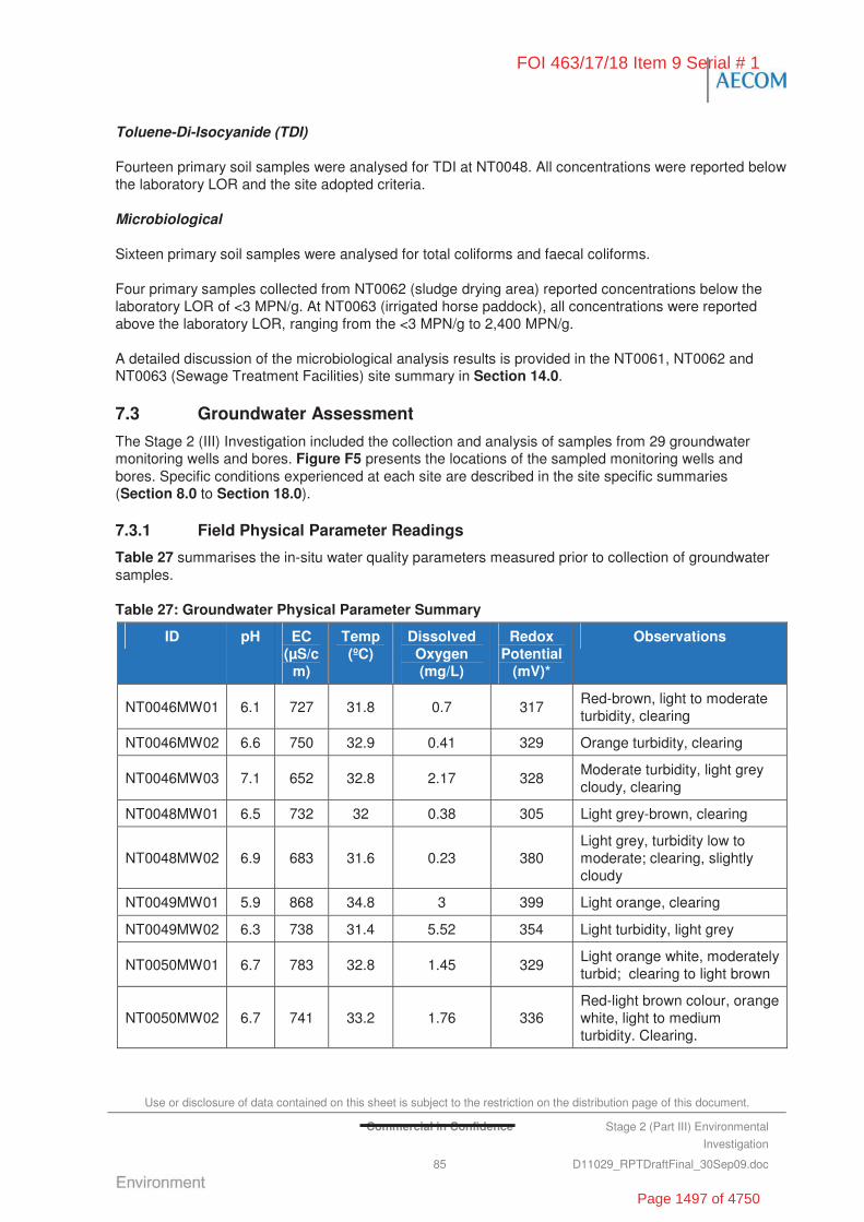
Use or disclosure of data contained on this sheet is subject to the restriction on the distribution page of this document.
Commercial in Confidence Stage 2 (Part III) Environmental
Investigation
85 D11029_RPTDraftFinal_30Sep09.doc
Toluene-Di-Isocyanide (TDI)
Fourteen primary soil samples were analysed for TDI at NT0048. All concentrations were reported below the laboratory LOR and the site adopted criteria.
Microbiological
Sixteen primary soil samples were analysed for total coliforms and faecal coliforms.
Four primary samples collected from NT0062 (sludge drying area) reported concentrations below the laboratory LOR of <3 MPN/g. At NT0063 (irrigated horse paddock), all concentrations were reported above the laboratory LOR, ranging from the <3 MPN/g to 2,400 MPN/g.
A detailed discussion of the microbiological analysis results is provided in the NT0061, NT0062 and NT0063 (Sewage Treatment Facilities) site summary in Section 14.0.
7.3 Groundwater Assessment
The Stage 2 (III) Investigation included the collection and analysis of samples from 29 groundwater monitoring wells and bores. Figure F5 presents the locations of the sampled monitoring wells and bores. Specific conditions experienced at each site are described in the site specific summaries (Section 8.0 to Section 18.0).
7.3.1 Field Physical Parameter Readings
Table 27 summarises the in-situ water quality parameters measured prior to collection of groundwater samples.
Table 27: Groundwater Physical Parameter Summary
ID pH EC (μS/c
m)
Temp (ºC)
Dissolved Oxygen (mg/L)
Redox Potential
(mV)*
Observations
NT0046MW01 6.1 727 31.8 0.7 317 Red-brown, light to moderate turbidity, clearing
NT0046MW02 6.6 750 32.9 0.41 329 Orange turbidity, clearing
NT0046MW03 7.1 652 32.8 2.17 328 Moderate turbidity, light grey cloudy, clearing
NT0048MW01 6.5 732 32 0.38 305 Light grey-brown, clearing
NT0048MW02 6.9 683 31.6 0.23 380 Light grey, turbidity low to moderate; clearing, slightly cloudy
NT0049MW01 5.9 868 34.8 3 399 Light orange, clearing
NT0049MW02 6.3 738 31.4 5.52 354 Light turbidity, light grey
NT0050MW01 6.7 783 32.8 1.45 329 Light orange white, moderately turbid; clearing to light brown
NT0050MW02 6.7 741 33.2 1.76 336 Red-light brown colour, orange white, light to medium turbidity. Clearing.
FOI 463/17/18 Item 9 Serial # 1
Page 1497 of 4750
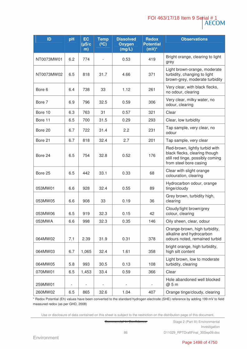
Use or disclosure of data contained on this sheet is subject to the restriction on the distribution page of this document.
Commercial in Confidence Stage 2 (Part III) Environmental
Investigation
86 D11029_RPTDraftFinal_30Sep09.doc
ID pH EC (μS/c
m)
Temp (ºC)
Dissolved Oxygen (mg/L)
Redox Potential
(mV)*
Observations
NT0073MW01 6.2 774 - 0.53 419 Bright orange, clearing to light grey
NT0073MW02 6.5 818 31.7 4.66 371 Light brown-orange, moderate turbidity, changing to light brown-grey, moderate turbidity
Bore 6 6.4 738 33 1.12 261 Very clear, with black flecks, no odour, clearing
Bore 7 6.9 796 32.5 0.59 306 Very clear, milky water, no odour, clearing
Bore 10 6.3 763 31 0.57 321 Clear
Bore 11 6.5 700 31.5 0.29 293 Clear, low turbidity
Bore 20 6.7 722 31.4 2.2 231 Tap sample, very clear, no odour
Bore 21 6.7 818 32.4 2.7 201 Tap sample, very clear
Bore 24 6.5 754 32.8 0.52 176
Red-brown, lightly turbid with black flecks, clearing though still red tinge, possibly coming from steel bore casing
Bore 25 6.5 442 33.1 0.33 68 Clear with slight orange colouration, clearing
053MW01 6.6 928 32.4 0.55 89 Hydrocarbon odour, orange tinge/cloudy
053MW05 6.6 908 33 0.19 36 Grey brown, turbidity high, clearing
053MW06 6.5 919 32.3 0.15 42 Cloudy/light brown/grey colour, clearing
053MWA 6.6 998 32.3 0.35 146 Oily sheen, clear, odour
064MW02 7.1 2.39 31.9 0.31 378
Orange-brown, high turbidity, alkaline and hydrocarbon odours noted, remained turbid
064MW03 6.7 1,065 32.4 1.61 358 bright orange, high turbidity, high silt content
064MW05 5.8 993 30.5 0.13 108 Light brown, low to moderate turbidity, clearing
070MW01 6.5 1,453 33.4 0.59 366 Clear
259MW01 - - - - - Hole abandoned well blocked @ 5 m
260MW02 6.5 865 32.6 1.04 407 Orange tinge/cloudy, clearing
* Redox Potential (Eh) values have been converted to the standard hydrogen electrode (SHE) reference by adding 199 mV to field
measured redox (as per GHD, 2008)
FOI 463/17/18 Item 9 Serial # 1
Page 1498 of 4750

Use or disclosure of data contained on this sheet is subject to the restriction on the distribution page of this document.
Commercial in Confidence Stage 2 (Part III) Environmental
Investigation
87 D11029_RPTDraftFinal_30Sep09.doc
7.3.2 Survey Results and Bore Construction Details
AECOM engaged a licensed surveyor to survey the newly installed wells and bores sampled during the Stage 2 (III) Investigation. Elevation data was measured for the ground surface and Top of Casing (ToC) at each well. The survey data was referenced to the Map Grid of Australia (MGA) and Australian Height Datum (AHD) to allow for integration with other data sources.
Survey results for the newly and previously installed wells sampled during the Stage 2 (III) Investigation are presented in Table 28.
Table 28: Survey Results for New and Existing Bores
Coordinates (WGS84) Id
Easting Northing
Ground Surface (mAHD)
ToC
(mAHD)
Relative SWL
(mAHD)^
NT0046MW01 -14.51937 132.36865 130.140 129.490 124.200
NT0046MW02 -14.52439 132.37105 131.740 131.210 125.670
NT0046MW03 -14.52622 132.37369 132.400 131.760 126.020
NT0048MW01 -14.51571 132.38083 132.980 132.360 127.080
NT0048MW02 -14.51639 132.38169 132.350 131.750 127.170
NT0049MW01 -14.51973 132.38381 133.050 132.660 126.160
NT0049MW02 -14.51395 132.38880 134.590 133.860 128.320
NT0050MW01 -14.53812 132.39512 137.750 137.140 130.840
NT0050MW02 -14.53678 132.39189 134.800 134.380 130.600
NT0065MW01 -14.52022 132.38023 131.750 132.29 130.145
NT0073MW01 -14.52687 132.39720 137.610 137.580 132.940
NT0073MW02 -14.52800 132.39809 138.020 137.300 130.790
Bore 6 -14.52640 132.39877 133.990 133.680 131.220
Bore 7 -14.52880 132.39874 132.570 132.260 122.960
Bore 10 -14.53373 132.37290 ND ND 126.150
Bore 11 -14.53849 132.37626 ND ND 126.410
Bore 20 -14.53502 132.37370 131.540 130.940 ND
Bore 21 -14.53400 132.40299 147.930 147.220 ND
Bore 24 -14.51703 132.37767 139.140 138.700 126.580
Bore 25 -14.51869 132.40794 137.520 137.580 132.600
053MW01* -14.50694 132.39729 ND 143.110 132.380
053MW05* -14.50747 132.39714 142.900 142.804 132.074
053MW06* -14.50730 132.39659 142.690 143.257 131.957
053MWB* -14.50694 132.39706 ND 142.990 132.350
064MW02* -14.53160 132.37620 ND 137.420 126.750
064MW03* -14.53134 132.37651 ND 134.290 126.830
064MW05* -14.53275 132.37502 133.921 133.270 125.740
FOI 463/17/18 Item 9 Serial # 1
Page 1499 of 4750
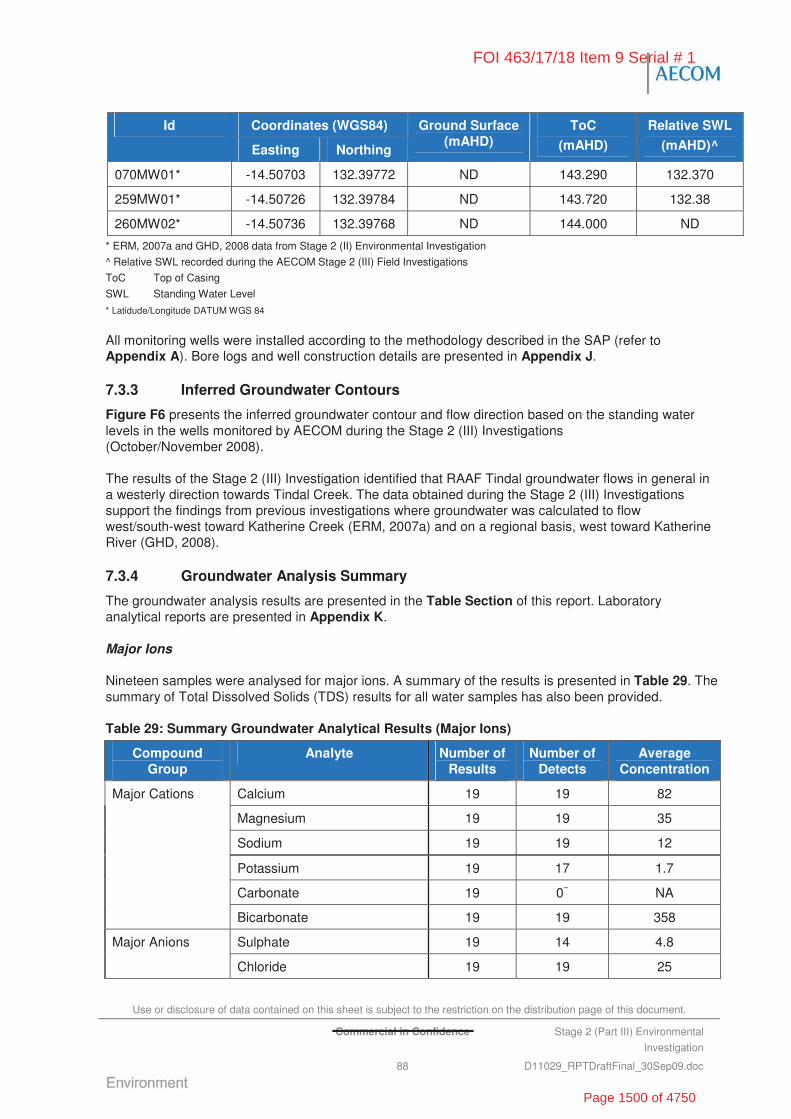
Use or disclosure of data contained on this sheet is subject to the restriction on the distribution page of this document.
Commercial in Confidence Stage 2 (Part III) Environmental
Investigation
88 D11029_RPTDraftFinal_30Sep09.doc
Coordinates (WGS84) Id
Easting Northing
Ground Surface (mAHD)
ToC
(mAHD)
Relative SWL
(mAHD)^
070MW01* -14.50703 132.39772 ND 143.290 132.370
259MW01* -14.50726 132.39784 ND 143.720 132.38
260MW02* -14.50736 132.39768 ND 144.000 ND
* ERM, 2007a and GHD, 2008 data from Stage 2 (II) Environmental Investigation
^ Relative SWL recorded during the AECOM Stage 2 (III) Field Investigations
ToC Top of Casing
SWL Standing Water Level
* Latidude/Longitude DATUM WGS 84
All monitoring wells were installed according to the methodology described in the SAP (refer to Appendix A). Bore logs and well construction details are presented in Appendix J.
7.3.3 Inferred Groundwater Contours
Figure F6 presents the inferred groundwater contour and flow direction based on the standing water levels in the wells monitored by AECOM during the Stage 2 (III) Investigations (October/November 2008).
The results of the Stage 2 (III) Investigation identified that RAAF Tindal groundwater flows in general in a westerly direction towards Tindal Creek. The data obtained during the Stage 2 (III) Investigations support the findings from previous investigations where groundwater was calculated to flow west/south-west toward Katherine Creek (ERM, 2007a) and on a regional basis, west toward Katherine River (GHD, 2008).
7.3.4 Groundwater Analysis Summary
The groundwater analysis results are presented in the Table Section of this report. Laboratory analytical reports are presented in Appendix K.
Major Ions
Nineteen samples were analysed for major ions. A summary of the results is presented in Table 29. The summary of Total Dissolved Solids (TDS) results for all water samples has also been provided.
Table 29: Summary Groundwater Analytical Results (Major Ions)
Compound Group
Analyte Number of Results
Number of Detects
Average Concentration
Calcium 19 19 82
Magnesium 19 19 35
Sodium 19 19 12
Potassium 19 17 1.7
Carbonate 19 0~ NA
Major Cations
Bicarbonate 19 19 358
Sulphate 19 14 4.8 Major Anions
Chloride 19 19 25
FOI 463/17/18 Item 9 Serial # 1
Page 1500 of 4750
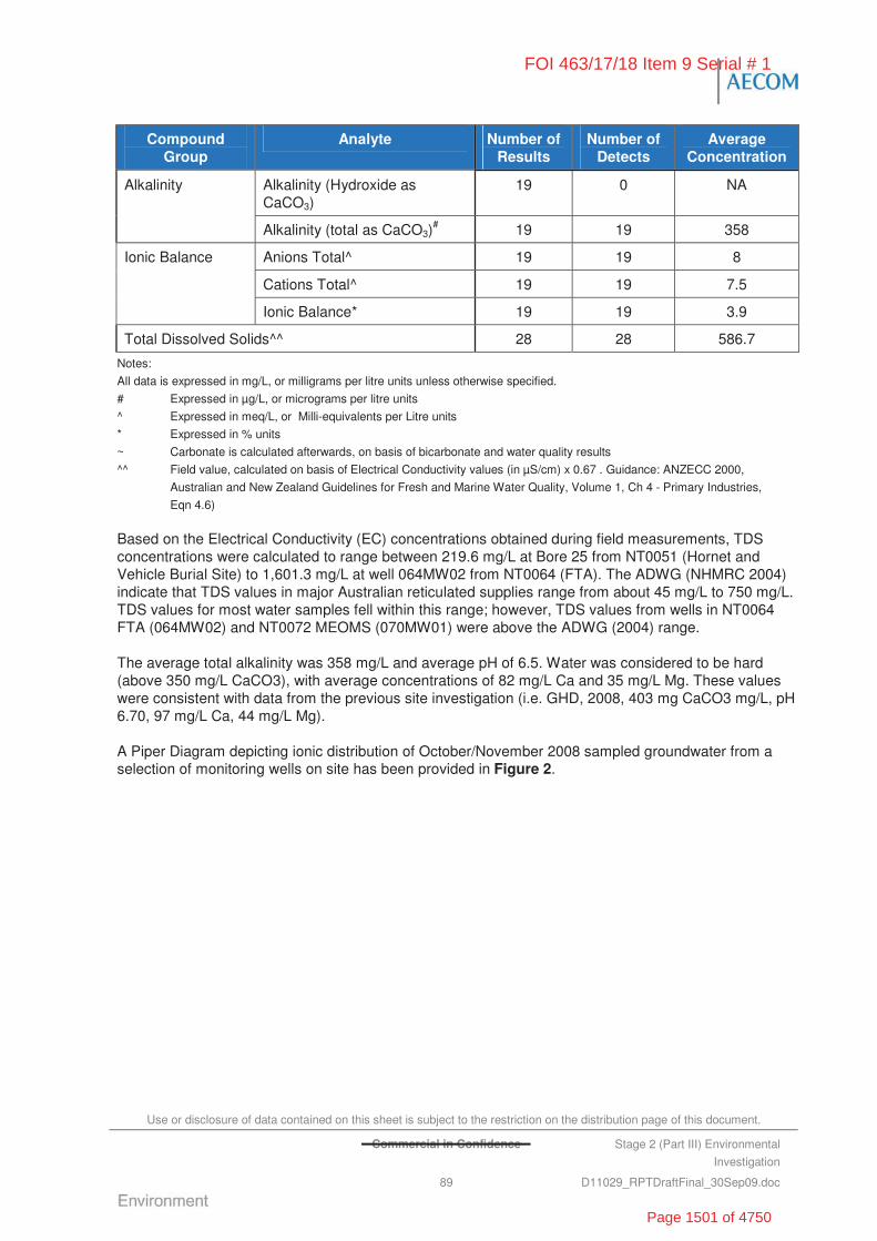
Use or disclosure of data contained on this sheet is subject to the restriction on the distribution page of this document.
Commercial in Confidence Stage 2 (Part III) Environmental
Investigation
89 D11029_RPTDraftFinal_30Sep09.doc
Compound Group
Analyte Number of Results
Number of Detects
Average Concentration
Alkalinity (Hydroxide as CaCO3)
19 0 NA Alkalinity
Alkalinity (total as CaCO3)# 19 19 358
Anions Total^ 19 19 8
Cations Total^ 19 19 7.5
Ionic Balance
Ionic Balance* 19 19 3.9
Total Dissolved Solids^^ 28 28 586.7
Notes:
All data is expressed in mg/L, or milligrams per litre units unless otherwise specified.
# Expressed in μg/L, or micrograms per litre units
^ Expressed in meq/L, or Milli-equivalents per Litre units
* Expressed in % units
~ Carbonate is calculated afterwards, on basis of bicarbonate and water quality results
^^ Field value, calculated on basis of Electrical Conductivity values (in μS/cm) x 0.67 . Guidance: ANZECC 2000,
Australian and New Zealand Guidelines for Fresh and Marine Water Quality, Volume 1, Ch 4 - Primary Industries,
Eqn 4.6)
Based on the Electrical Conductivity (EC) concentrations obtained during field measurements, TDS concentrations were calculated to range between 219.6 mg/L at Bore 25 from NT0051 (Hornet and Vehicle Burial Site) to 1,601.3 mg/L at well 064MW02 from NT0064 (FTA). The ADWG (NHMRC 2004) indicate that TDS values in major Australian reticulated supplies range from about 45 mg/L to 750 mg/L. TDS values for most water samples fell within this range; however, TDS values from wells in NT0064 FTA (064MW02) and NT0072 MEOMS (070MW01) were above the ADWG (2004) range.
The average total alkalinity was 358 mg/L and average pH of 6.5. Water was considered to be hard (above 350 mg/L CaCO3), with average concentrations of 82 mg/L Ca and 35 mg/L Mg. These values were consistent with data from the previous site investigation (i.e. GHD, 2008, 403 mg CaCO3 mg/L, pH 6.70, 97 mg/L Ca, 44 mg/L Mg).
A Piper Diagram depicting ionic distribution of October/November 2008 sampled groundwater from a selection of monitoring wells on site has been provided in Figure 2.
FOI 463/17/18 Item 9 Serial # 1
Page 1501 of 4750
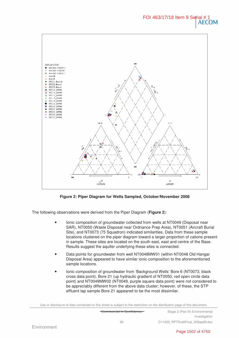
Use or disclosure of data contained on this sheet is subject to the restriction on the distribution page of this document.
Commercial in Confidence Stage 2 (Part III) Environmental
Investigation
90 D11029_RPTDraftFinal_30Sep09.doc
Figure 2: Piper Diagram for Wells Sampled, October/November 2008
The following observations were derived from the Piper Diagram (Figure 2):
• Ionic composition of groundwater collected from wells at NT0049 (Disposal near SAR), NT0050 (Waste Disposal near Ordnance Prep Area), NT0051 (Aircraft Burial Site), and NT0073 (75 Squadron) indicated similarities. Data from these sample locations clustered on the piper diagram toward a larger proportion of cations present in sample. These sites are located on the south east, east and centre of the Base. Results suggest the aquifer underlying these sites is connected.
• Data points for groundwater from well NT0048MW01 (within NT0048 Old Hangar Disposal Area) appeared to have similar ionic composition to the aforementioned sample locations.
• Ionic composition of groundwater from ‘Background Wells’ Bore 6 (NT0073, black cross data point), Bore 21 (up hydraulic gradient of NT0050, red open circle data point) and NT0049MW02 (NT0049, purple square data point) were not considered to be appreciably different from the above data cluster; however, of these, the STP effluent tap sample Bore 21 appeared to be the most dissimilar.
FOI 463/17/18 Item 9 Serial # 1
Page 1502 of 4750
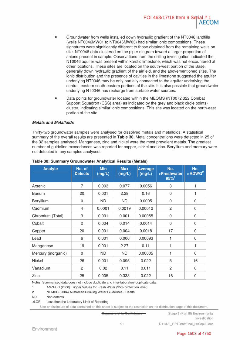
Use or disclosure of data contained on this sheet is subject to the restriction on the distribution page of this document.
Commercial in Confidence Stage 2 (Part III) Environmental
Investigation
91 D11029_RPTDraftFinal_30Sep09.doc
• Groundwater from wells installed down hydraulic gradient of the NT0046 landfills (wells NT0046MW01 to NT0046MW03) had similar ionic compositions. These signatures were significantly different to those obtained from the remaining wells on site. NT0046 data clustered on the piper diagram toward a larger proportion of anions present in sample. Observations from the drilling investigation indicated the NT0046 aquifer was present within karstic limestone, which was not encountered at other locations. These sites are located on the south-west portion of the Base, generally down hydraulic gradient of the airfield, and the abovementioned sites. The ionic distribution and the presence of cavities in the limestone suggested the aquifer underlying NT0046 may be only partially connected to the aquifer underlying the central, eastern south-eastern portions of the site. It is also possible that groundwater underlying NT0046 has recharge from surface water sources.
• Data points for groundwater located within the MEOMS (NT0072 322 Combat Support Squadron (CSS) area) as indicated by the grey and black circle points) cluster, indicating similar ionic compositions. This site was located on the north-east portion of the site.
Metals and Metalloids
Thirty-two groundwater samples were analysed for dissolved metals and metalloids. A statistical summary of the overall results are presented in Table 30. Metal concentrations were detected in 25 of the 32 samples analysed. Manganese, zinc and nickel were the most prevalent metals. The greatest number of guideline exceedances was reported for copper, nickel and zinc. Beryllium and mercury were not detected in any samples analysed.
Table 30: Summary Groundwater Analytical Results (Metals)
Analyte No. of Detects
Min (mg/L)
Max (mg/L)
Average (mg/L)
No. >Freshwater
95%1
No. >ADWG2
Arsenic 7 0.003 0.077 0.0056 3 1
Barium 20 0.001 2.28 0.16 0 1
Beryllium 0 ND ND 0.0005 0 0
Cadmium 4 0.0001 0.0019 0.00012 2 0
Chromium (Total) 3 0.001 0.001 0.00055 0 0
Cobalt 2 0.004 0.014 0.0014 0 0
Copper 20 0.001 0.004 0.0018 17 0
Lead 6 0.001 0.006 0.00093 1 0
Manganese 19 0.001 2.27 0.11 1 1
Mercury (inorganic) 0 ND ND 0.00005 1 0
Nickel 26 0.001 0.095 0.022 5 16
Vanadium 2 0.02 0.11 0.011 2 0
Zinc 25 0.005 0.333 0.022 16 0
Notes: Summarised data does not include duplicate and inter-laboratory duplicate data.
1 ANZECC (2000) Trigger Values for Fresh Water (95% protection level)
2 NHMRC (2004) Australian Drinking Water Guidelines - Health
ND Non detects
<LOR Less then the Laboratory Limit of Reporting
FOI 463/17/18 Item 9 Serial # 1
Page 1503 of 4750

Use or disclosure of data contained on this sheet is subject to the restriction on the distribution page of this document.
Commercial in Confidence Stage 2 (Part III) Environmental
Investigation
92 D11029_RPTDraftFinal_30Sep09.doc
Total Petroleum Hydrocarbons (TPH)
Thirty-two groundwater samples were analysed for TPH. A summary of the results is presented in Table 31.
Table 31: Summary of Groundwater Analytical Results (TPH Fractions)
Analyte No. of Detects
Min Detect (μg/L)
Max Detect (μg/L)
Average (μg/L)
No. >DIV (VROM 2000)1
C6-C9 2 4,850 7,230 412 NA
C10-C14 2 200 960 62 NA
C15-C28 5 100 600 105 NA
C29-C36 3 60 180 36 NA
C10-C36 10 100 1,560 203 2
Notes:
1 Dutch Groundwater Intervention Values (DIV) (2004).
NA Not Applicable
Summarised data does not include duplicate and inter-laboratory duplicate data.
A total of 32 groundwater samples were analysed for volatile TPH fractions (TPH C6-C9). Of these, two samples (from wells at NT0072 322 CSS Area) reported concentrations above laboratory LOR.
Similarly, a total of 32 groundwater samples were analysed for semi volatile TPH fractions (TPH C10-C36). Ten samples reported concentrations above laboratory LOR, of these two sample result concentrations (one from a well at NT0072 322 CSS Area, and one from effluent tap at NT0061 STP) were in exceedance of the adopted guidelines.
Benzene, Toluene, Ethyl-benzene and Xylene (BTEX)
A total of 30 water samples were analysed for the BTEX compound suite. A summary of the results is presented in Table 32.
Table 32: Summary of Groundwater Analytical Results (BTEX)
Analyte No. of Detects
Min Detect (μg/L)
Max Detect (μg/L)
Average (μg/L)
No. >Freshwater
95%1
No. >ADWG2
Benzene 2 3,120 4,500 256 2 2 (20 due to raised
LOR)
Ethylbenzene 2 165 270 16 2 2
Toluene 2 9 69 4.4 0 0
Xylene (m & p) 2 177 331 19 2 0
Xylene (o) 1 35 35 3.1 0 0
Notes:
1 ANZECC (2000) Trigger Values for Fresh Water (95% protection level)
2 NHMRC (2004) Australian Drinking Water Guidelines - Health
<LOR Less then the Laboratory Limit of Reporting
Summarised data does not include duplicate and inter-laboratory duplicate data.
FOI 463/17/18 Item 9 Serial # 1
Page 1504 of 4750

Use or disclosure of data contained on this sheet is subject to the restriction on the distribution page of this document.
Commercial in Confidence Stage 2 (Part III) Environmental
Investigation
93 D11029_RPTDraftFinal_30Sep09.doc
Of these, two samples reported BTEX compounds above laboratory LORs. Both these samples (from wells at NT0072 322 CSS Area) reported BTEX concentrations in exceedance of the adopted guidelines.
A detailed discussion of the BTEX analysis results has been provided in the NT0072 (322 CSS Area) site summary in Section 17.0.
Volatile Organic Compounds (VOCs)
Twenty-four water samples were analysed for the full suite of Monocyclic Aromatic Hydrocarbons (MAH). Two samples were collected at NT0072 area of interest which reported MAH compounds (i.e. 1,2,4-trimethylbenzene, 1,3,5-trimethylbenzene and n-propylbenzene) but below the Laboratory LOR.
A detailed discussion of the VOC analysis results has been provided in the NT0072 (322 CSS Area) site summary in Section 17.0.
Semi-Volatile Organic Compounds (SVOCs)
Twenty-four water samples were analysed for the full suite of Semi-Volatile Organic Compounds (SVOCs). From this, one sample (from a well situated within NT0072 322 CSS) reported a single SVOC above laboratory LOR. All results were below the adopted guidelines.
Twenty-seven water samples were analysed for Polynuclear Aromatic Hydrocarbons (PAHs) and Phenol compounds. With the exception of results from two samples (from wells situated within NT0072 322 CSS), all PAH and Phenol concentrations were reported below laboratory LORs and below adopted screening criteria.
A detailed discussion of the SVOC analysis results is provided in the NT0072 (322 CSS Area) site summary in Section 17.0.
Explosive Compounds
Up to 24 water samples were analysed for Explosives compounds. All sample concentrations were reported at concentrations below the laboratory LORs and below the adopted guidelines.
Nutrients
Twenty groundwater and waste water samples were analysed for ammonia. Of these, nine samples reported ammonia concentrations above the laboratory LOR. Detect concentrations reported from the laboratory ranged from 0.03 to 17 mg/L. Of these, three water samples collected from NT0061 (Sewage Treatment Facilities) exceeded the ANZECC (2000) Fresh Water 95% trigger value of 0.9 mg/L.
Up to 20 samples were analysed for Oxides of Nitrogen (Nitrate, Nitrite, Total NOx). Of the samples analysed, concentrations of above the laboratory limit of reporting were recorded in 14 samples for Nitrate, seven samples for Nitrite, and 19 samples for NOx. Sample result concentrations above the laboratory LOR ranged from 0.01 mg/L to 0.32 mg/L for Nitrate, 0.01 mg/L to 0.01 mg/L for Nitrite, and 0.01 mg/L to 12.2 mg/L for NOx.
Six groundwater samples were analysed for Phosphorus (P). Of the samples analysed, concentrations above the laboratory LOR were recorded in four samples collected from within and downgradient of NT0061 (Sewage Treatment Facilities). All detect results were reported at concentrations exceeding the adopted screening guidelines.
A detailed discussion of the nutrient analysis results is provided in the NT0061 (Sewage Treatment Facilities) site summary in Section 14.0.
FOI 463/17/18 Item 9 Serial # 1
Page 1505 of 4750
Use or disclosure of data contained on this sheet is subject to the restriction on the distribution page of this document.
Commercial in Confidence Stage 2 (Part III) Environmental
Investigation
94 D11029_RPTDraftFinal_30Sep09.doc
Radium-226
One groundwater sample from Bore 25 in NT0051 (Hornet and Vehicle Burial Area) was analysed for the radioisotope Radium-226 (Ra226). In this instance, Ra226 in groundwater was reported at levels below the laboratory LOR.
A detailed discussion of the Radium-226 analysis results is provided in the NT0051 (Hornet and Vehicle Burial Area) site summary in Section 12.0.
Pefluorochemicals
Twelve groundwater and waste water samples were analysed for Perfluorochemicals, which included PFOA and PFOS.
PFOA was detected at concentrations above laboratory LOR in two groundwater samples from NT0064 (FTA) and one sample from NT0065 (Fire Station). PFOS was detected at concentrations above laboratory LOR in three groundwater samples from NT0064 (FTA), three effluent and pond samples from NT0061 (Sewage Treatment Facilities), one groundwater sample down gradient of area NT0061 (Sewage Treatment Facilities) and one groundwater sample down gradient of NT0051 (Hornet and Vehicle Burial Site).
Exceedances of the adopted MDH (2009) guideline for groundwater were reported in three samples for PFOA and three samples for PFOS. Samples reporting Perflouro Chemicals (PFC) in exceedance of adopted criteria were obtained from wells within NT0064 (FTA) and the well downgradient of NT0065 (Fire Station).
A detailed discussion of the PFOS/PFOA analysis results is provided in the NT0064 (FTA) site summary in Section 15.0 and NT0065 (Fire Station) site summary in Section 16.0.
Microbiological
One groundwater and four waste water samples (influent, in-treatment and effluent) were analysed for total coliforms and faecal coliforms.
Total coliforms concentrations ranged from:
• 19,863 colony-forming units per 100 millilitre (CFU/100 mL) at Bore 20
• 521 CFU/100 mL to 488,400 CFU/100 mL in the waste water stream
• 1,000 CFU/100 mL,which is below the ANZECC (2000) guideline, in the effluent sample.
A detailed discussion of the microbiological analysis results is provided in the NT0061, NT0062 and NT0063 (Sewage Treatment facilities) site summary in Section 14.0.
7.3.5 Natural Attenuation Parameters
The effectiveness of natural attenuation processes is typically controlled by the contaminants of concern, and the physical, chemical, biological and hydrogeological properties of the soil and groundwater. Natural attenuation processes are largely complex oxidation and reduction processes which under favourable conditions, reduce the risks to human health and the environment by:
• transformation of the contaminants by destruction, degradation and abiotic transformation to less hazardous forms
FOI 463/17/18 Item 9 Serial # 1
Page 1506 of 4750
Use or disclosure of data contained on this sheet is subject to the restriction on the distribution page of this document.
Commercial in Confidence Stage 2 (Part III) Environmental
Investigation
95 D11029_RPTDraftFinal_30Sep09.doc
• reduction of contaminant concentrations
• reduction of contaminant mobility or bioavailability.
The rate, type of microbial population and the level of activity is controlled by the concentration of the electron receptors, substrates that can be used by the bacteria and the specific indigenous bacterial population.
The following summarises the progression from aerobic to anaerobic conditions:
• Oxygen to Nitrate Reduction: As available oxygen is consumed, the active aerobic bacteria shift to nitrate respiration. The denitrification will continue until the nitrate or useable carbon is depleted.
• Nitrate to Manganese Reduction: As the nitrate is depleted manganese-reducing bacteria will become active until the concentrations of manganese oxide become limiting.
• Manganese to Iron Reduction: Iron reduction becomes predominant once all the manganese oxides are depleted. Bacterial Mn(IV) respiration also appears to be limited to areas where sulfate is virtually absent.
• Iron to Sulfate Reduction: Iron reduction continues until it is limited by the substrate or carbon availability. Sulfate reduction then becomes dominant.
• Sulfate Reduction to Methanogenesis: Once sulfate or useable carbon is depleted methanogenic bacteria become dominant.
Native organic matter, measured as Total Organic Carbon (TOC), may also support reduction of iron and is therefore considered an indicator of suitable conditions for bacterial activity.
A positive correlation exists between zones of microbial activity and increased alkalinity. Increases in alkalinity result from the dissolution of clays by the production of carbon dioxide from the metabolism of microorganisms. Alkalinity is important in the maintenance of groundwater pH as it buffers the groundwater system against acids generated during both aerobic and anaerobic biodegradation. Concentrations of calcium, magnesium, potassium, sodium, total anions and total cations provide additional indicators of dissolution processes and buffering capacity.
Six monitoring wells were selected for the analysis of natural attenuation parameters at NT0072 MEOMS. Specific analytes included:
• Major Anions (Cl, SO4, Alkalinity)
• Minor Anions (Nitrate, Nitrite, Fluoride and Reactive P)
• Major Cations (Ca, Mg, Na and K)
• Sulphide
• Ferric Iron, Ferrous Iron and Dissolved Iron
• Ammonia
• Methane
• Total Organic Carbon (TOC).
A detailed discussion of the s results is provided in the NT0072 (MEOMS) site summary in Section 17.5.2.
FOI 463/17/18 Item 9 Serial # 1
Page 1507 of 4750

Use or disclosure of data contained on this sheet is subject to the restriction on the distribution page of this document.
Commercial in Confidence Stage 2 (Part III) Environmental
Investigation
96 D11029_RPTDraftFinal_30Sep09.doc
“This page has been left blank intentionally”
FOI 463/17/18 Item 9 Serial # 1
Page 1508 of 4750
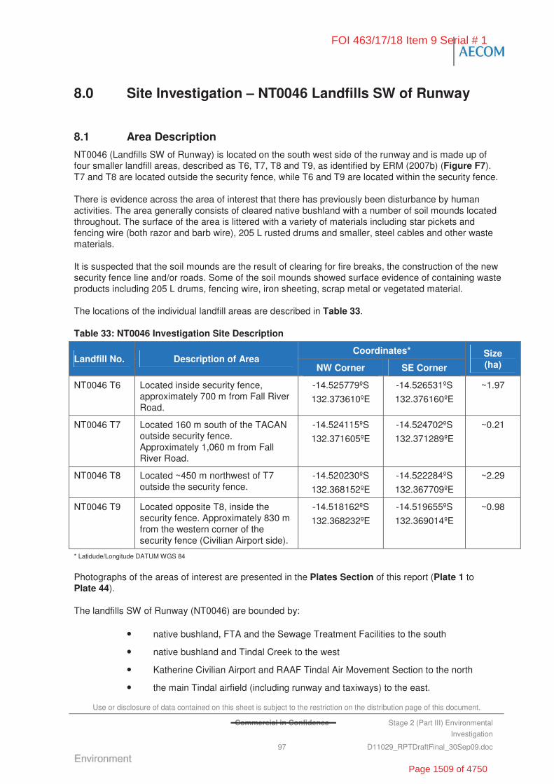
Use or disclosure of data contained on this sheet is subject to the restriction on the distribution page of this document.
Commercial in Confidence Stage 2 (Part III) Environmental
Investigation
97 D11029_RPTDraftFinal_30Sep09.doc
8.0 Site Investigation – NT0046 Landfills SW of Runway
8.1 Area Description
NT0046 (Landfills SW of Runway) is located on the south west side of the runway and is made up of four smaller landfill areas, described as T6, T7, T8 and T9, as identified by ERM (2007b) (Figure F7). T7 and T8 are located outside the security fence, while T6 and T9 are located within the security fence.
There is evidence across the area of interest that there has previously been disturbance by human activities. The area generally consists of cleared native bushland with a number of soil mounds located throughout. The surface of the area is littered with a variety of materials including star pickets and fencing wire (both razor and barb wire), 205 L rusted drums and smaller, steel cables and other waste materials.
It is suspected that the soil mounds are the result of clearing for fire breaks, the construction of the new security fence line and/or roads. Some of the soil mounds showed surface evidence of containing waste products including 205 L drums, fencing wire, iron sheeting, scrap metal or vegetated material.
The locations of the individual landfill areas are described in Table 33.
Table 33: NT0046 Investigation Site Description
Coordinates* Landfill No. Description of Area
NW Corner SE Corner
Size (ha)
NT0046 T6 Located inside security fence, approximately 700 m from Fall River Road.
-14.525779ºS
132.373610ºE
-14.526531ºS
132.376160ºE
~1.97
NT0046 T7 Located 160 m south of the TACAN outside security fence. Approximately 1,060 m from Fall River Road.
-14.524115ºS
132.371605ºE
-14.524702ºS
132.371289ºE
~0.21
NT0046 T8 Located ~450 m northwest of T7 outside the security fence.
-14.520230ºS
132.368152ºE
-14.522284ºS
132.367709ºE
~2.29
NT0046 T9 Located opposite T8, inside the security fence. Approximately 830 m from the western corner of the security fence (Civilian Airport side).
-14.518162ºS
132.368232ºE
-14.519655ºS
132.369014ºE
~0.98
* Latidude/Longitude DATUM WGS 84
Photographs of the areas of interest are presented in the Plates Section of this report (Plate 1 to Plate 44).
The landfills SW of Runway (NT0046) are bounded by:
• native bushland, FTA and the Sewage Treatment Facilities to the south
• native bushland and Tindal Creek to the west
• Katherine Civilian Airport and RAAF Tindal Air Movement Section to the north
• the main Tindal airfield (including runway and taxiways) to the east.
FOI 463/17/18 Item 9 Serial # 1
Page 1509 of 4750
Use or disclosure of data contained on this sheet is subject to the restriction on the distribution page of this document.
Commercial in Confidence Stage 2 (Part III) Environmental
Investigation
98 D11029_RPTDraftFinal_30Sep09.doc
8.2 Objectives
To meet the overall objective of the Stage 2 (III) Investigation of defining the ‘true risks’ to Defence of potential contamination, NT0046 (Landfills SW of Runway) were investigated to:
• delineate the vertical and lateral extent of landfill material and chemical contamination (to the extent practical)
• quantify and characterise waste material within landfill
• measure concentrations of contaminants within groundwater and soils
• identify potential human health and ecological receptors
• assess the potential for waste materials and/or impacted soils to leach contaminants of concern into groundwater and receiving waters.
8.3 Historical Information, Previous Investigations and Potential Chemicals of Concern
8.3.1 Previous Reports
The Landfill/Burial Sites Stage 1 Environmental Investigation (Stage 1 EI) prepared by ERM (2007b) included consideration of NT0046 (Landfills SW of Runway).
The Stage 1 EI (ERM, 2007b) reported that the disposal areas were constructed around the 1960s or 1970s and were associated with ordnance loading aprons and scrapings. Visual observations identified that materials disposed in the area included green waste, 205 L rusted drums (contents unknown), and disused building materials and rubble (i.e. concrete, ACM and scrap metal). Visual observations also suggested that the areas were no longer used for waste disposal. Discussions with a Base contact reportedly suggested that ordnance disposal in these areas was unlikely, however could not be ruled out.
The Stage 1 EI concluded that NT0046 posed a medium risk based on human exposure to contaminated groundwater or surface water.
Recommendations from the Stage 1 Investigation were:
• fencing of the area
• conduct a geophysical Investigation
• possible groundwater monitoring.
8.3.2 Historical Aerial Photographs
A limited review of the available historical aerial photographs at the office of Defence Support – Tindal (DS-Tindal) was undertaken during the Stage 2 (III) Investigations to assist in identifying the areas of concern.
The photographs showed evidence of a history of disturbance across the areas. The photographs also showed three ponds at T6.
8.3.3 Potential Chemicals of Concern
Based on the available historical information, the potential chemicals of concern at NT0046 include:
FOI 463/17/18 Item 9 Serial # 1
Page 1510 of 4750
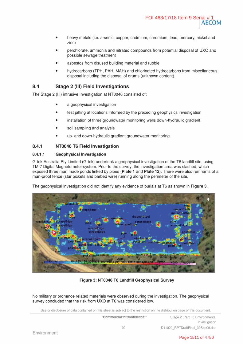
Use or disclosure of data contained on this sheet is subject to the restriction on the distribution page of this document.
Commercial in Confidence Stage 2 (Part III) Environmental
Investigation
99 D11029_RPTDraftFinal_30Sep09.doc
• heavy metals (i.e. arsenic, copper, cadmium, chromium, lead, mercury, nickel and zinc)
• perchlorate, ammonia and nitrated compounds from potential disposal of UXO and possible sewage treatment
• asbestos from disused building material and rubble
• hydrocarbons (TPH, PAH, MAH) and chlorinated hydrocarbons from miscellaneous disposal including the disposal of drums (unknown content).
8.4 Stage 2 (III) Field Investigations
The Stage 2 (III) intrusive Investigation at NT0046 consisted of:
• a geophysical investigation
• test pitting at locations informed by the preceding geophysics investigation
• installation of three groundwater monitoring wells down-hydraulic gradient
• soil sampling and analysis
• up- and down-hydraulic gradient groundwater monitoring.
8.4.1 NT0046 T6 Field Investigation
8.4.1.1 Geophysical Investigation
G-tek Australia Pty Limited (G-tek) undertook a geophysical investigation of the T6 landfill site, using TM-7 Digital Magnetometer system. Prior to the survey, the investigation area was slashed, which exposed three man made ponds linked by pipes (Plate 1 and Plate 12). There were also remnants of a man-proof fence (star pickets and barbed wire) running along the perimeter of the site.
The geophysical investigation did not identify any evidence of burials at T6 as shown in Figure 3.
Figure 3: NT0046 T6 Landfill Geophysical Survey
No military or ordnance related materials were observed during the investigation. The geophysical survey concluded that the risk from UXO at T6 was considered low.
FOI 463/17/18 Item 9 Serial # 1
Page 1511 of 4750

Use or disclosure of data contained on this sheet is subject to the restriction on the distribution page of this document.
Commercial in Confidence Stage 2 (Part III) Environmental
Investigation
100 D11029_RPTDraftFinal_30Sep09.doc
The detailed report prepared by G-Tek has been included Appendix C.
8.4.1.2 Soil Investigation
The soil investigation was undertaken on 21 and 22 October 2008 and comprised the following works:
• The excavation of four test pits (NT0046T6TP01 to NT0046T6TP04) to a maximum depth of 2.0 m bgl. The test pits were located across the central portion of the inferred landfill and targeted, in particular, the former ponds that were observed in the area.
• The drilling of one soil bore (NT0046T6BH01) to a depth of 11 mbgl for the installation of a monitoring well. Installation of a monitoring well was not possible due to the bore intersecting a limestone cavern and the bore was abandoned. The soil bore was located west, down hydraulic gradient, of the former ponds.
• The drilling of a second soil bore to a depth of 6.6 mbgl and groundwater monitoring well NT0046MW03 installed. The groundwater monitoring well was located approximately 10 m east of NT0046T6BH01.
The soil sampling and groundwater monitoring locations are presented on Figure F8. The logs describing the subsurface soil profile and groundwater monitoring well construction have been provided in Appendix H and Appendix J, respectively.
PID screening of soil samples did not suggest the presence of volatiles with PID readings ranging from 0 ppm to 1.2 ppm.
Fill Material
No fill materials were encountered at T6 during the Stage 2 (III) Investigations.
Natural Soil and Rock
The stratigraphy encountered down hydraulic gradient of the site at soil bore NT0046T6BH01 and NT0046MW03 comprised silty and gravelly clays grading to clayey limestone gravels at greater depth. Bedrock was encountered at 9.2 mbgl and consisted of highly weathered porous limestone with cavities containing a fine sand and water slurry.
NT0046T6BH01 was initially drilled to approximately 11 mbgl, with the objective of installing a groundwater well to intercept the groundwater inflow observed at 9.2 mbgl. Installation of a groundwater monitoring well was subsequently found to be impossible due to the loss of filter sand when attempting to backfill the annulus around the standpipe. In particular, the well annulus could not be backfilled beyond 7.2 mbgl suggesting that at this point, the weight of sand was sufficient to displace the sand slurry which filled the limestone cavity intersected by the bore. Subsequent attempts to remove the standpipe and re-drill were unsuccessful as the sand slurry quickly filled the hole to 7.2 mbgl.
NT0046T6BH01 was abandoned by grouting from the surface to a depth of at least 11 mbgl in order to prevent any potential contamination pathway into the limestone. The well standpipe was removed prior to grouting. The grout consisted of a quick set plaster, cement and hydrated bentonite slurry which was placed progressively in three stages over the space of a week. The staged grouting was designed to allow the grout to set and bridge the hole without applying sufficient weight to displace the slurry within the limestone cavity.
NT0046MW03 was later installed 10 m to the east of NT0046T6BH01 in a soil bore drilled to a depth of 6.6 mbgl. The depth of the well was limited to ensure no breaching of the limestone aquifer. While the well did not intercept groundwater at the time of installation, it was anticipated that it would intercept
FOI 463/17/18 Item 9 Serial # 1
Page 1512 of 4750
Use or disclosure of data contained on this sheet is subject to the restriction on the distribution page of this document.
Commercial in Confidence Stage 2 (Part III) Environmental
Investigation
101 D11029_RPTDraftFinal_30Sep09.doc
groundwater during the seasonal rise associated with the wet season (which has been recorded to be in the order of 2 m).
8.4.1.3 Groundwater Investigation
The groundwater investigation was undertaken on 10 November 2008. One groundwater sample was collected from the newly installed monitoring well NT0046MW03.
As described above, groundwater inflow in soil bore NT0046T6BH01 was encountered at 9.2 mbgl, within the porous and cavernous limestone bedrock. Inflow was not encountered in the shallower well NT0046MW03 (which was terminated at 6.6 mbgl). The standing water level measured a week after installation and development of NT0046MW03 at 5.67 m below top of casing (BTOC).
Groundwater encountered during drilling of NT0046T6BH01 had an odour above the observed ground water inflow at 9.2 mbgl. This odour was not evident at greater depths. PID screening of the drill cuttings did not indicate the presence of volatiles (all readings < 0.4 ppm). Groundwater encountered during drilling NT0046MW03 was not odorous, and PID screening of the drill cuttings did not indicate the presence of volatiles (all results < 0.1 ppm).
8.4.2 NT0046 T7 Landfill Subsurface Investigation
8.4.2.1 Geophysical Investigation
G-tek undertook a geophysical investigation of the T7 landfill site, using TM-7 Digital Magnetometer system. Prior to the survey, the investigation area was slashed, which exposed a disturbed area showing partially exposed drums at the surface and an earth mound in the eastern corner (Plate 13 to Plate 21).
The geophysical investigation identified a large rectangular burial (~60 m x 25 m) which was interpreted to consist of several “strips” of steel material. The findings of the geophysical investigation at T7 are shown in Figure 4.
Figure 4: NT0046 T7 Landfill Geophysical Survey
FOI 463/17/18 Item 9 Serial # 1
Page 1513 of 4750
Use or disclosure of data contained on this sheet is subject to the restriction on the distribution page of this document.
Commercial in Confidence Stage 2 (Part III) Environmental
Investigation
102 D11029_RPTDraftFinal_30Sep09.doc
No military or ordnance related materials were observed during the investigation. The geophysical investigation identified the risk from UXO at T7 was considered low.
The detailed report prepared by G-Tek has been included in Appendix C.
8.4.2.2 Soil Investigation
The soil investigation was undertaken on 23 October 2008 and comprised the following works:
• Four test pits (NT0046T7TP01 to NT0046T7TP04) were excavated to a maximum depth of 4.0 mbgl. The test pits were located to target the burial identified by the preceding geophysical investigation.
• One soil bore (NT0046T7BH01) was drilled to a depth of 11.8 mbgl for the installation of a monitoring well (NT0046MW02). The soil bore was located south (down hydraulic gradient) of the burial identified by the geophysical investigation.
The soil sampling and groundwater monitoring locations are presented on Figure F9. Logs describing the subsurface soil profile and groundwater monitoring well construction are provided in Appendix H and Appendix J.
PID screening of soil samples did not suggest the presence of volatiles with readings ranging from 0.2 to 1.2 ppm.
Fill Material
Surface fill materials encountered at T7 were largely concentrated in the area of surface disturbance in the centre of the clearing. Rusted scrap metal (sheet and wires) were present in various locations across the surface of the area. Clusters of waste metal are evident in the results of the geophysical investigation (refer Figure 4).
Buried fill was encountered south-west of the mound in test pit NT0046T7TP04, to a depth of 2 mbgl. The fill material consisted of grey brown clays, containing potential ACM (Plate 20) and metal fragments, including 205 L steel drums (Plate 19). The drums where flattened, had no lids and did not appear to contain any liquids. Similar grey brown clays (potential fill) were also encountered west of the mound in test pit NT0046T7TP03, to a depth of 2 mbgl. A tangle of razor wire was also encountered in test pit NT0046T7TP02 located south of the earth mound (Plate 13).
No buried fill was encountered in the test pit excavated on the eastern side of the mound and clearing (NT0046T7TP01).
Natural Soil and Rock
The stratigraphy encountered in the western portion of the area generally comprised of fill from the surface to 2 mbgl, overlying orange-brown gravelly clays (test pits NT0046T7TP03 and NT0046T7TP04).
The stratigraphy encountered in the eastern portion of the area generally comprised red-orange medium plasticity silty clays from the surface to up to 2.5 mbgl, overlying grey-brown limestone cobbles (test pits NT0046T7TP01 and NT0046T7TP02), and limestone boulders at 3 mbgl (test pit NT0046T7TP01).
Monitoring well NT0046MW02 was constructed immediately down hydraulic gradient of the landfill clearing. Soils encountered were red-orange clayey silts, consistent with the surface soil units encountered in the eastern portion of the clearing. The silt strata overlaid red-orange siltstone/mudstone rock at 2.5 mbgl. Rock below 2.5 mbgl comprised alternating beds of orange-brown mudstone/siltstone and grey-brown limestone of variable weathering and porosity.
FOI 463/17/18 Item 9 Serial # 1
Page 1514 of 4750
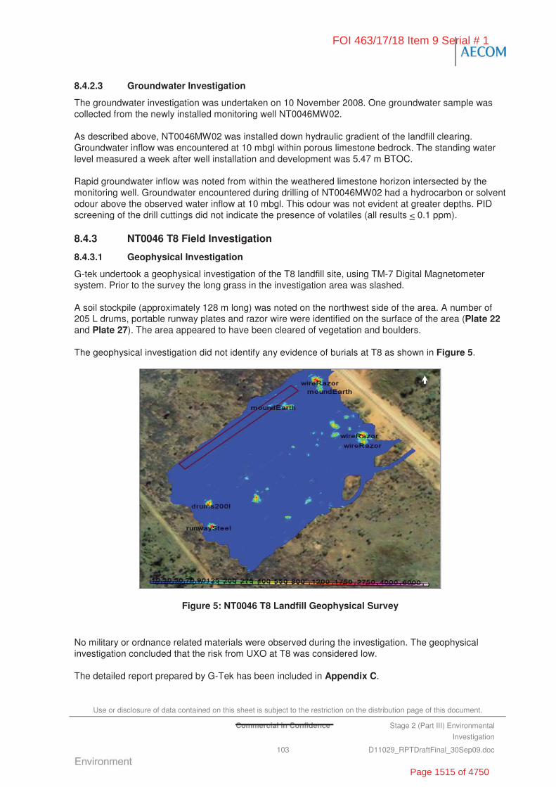
Use or disclosure of data contained on this sheet is subject to the restriction on the distribution page of this document.
Commercial in Confidence Stage 2 (Part III) Environmental
Investigation
103 D11029_RPTDraftFinal_30Sep09.doc
8.4.2.3 Groundwater Investigation
The groundwater investigation was undertaken on 10 November 2008. One groundwater sample was collected from the newly installed monitoring well NT0046MW02.
As described above, NT0046MW02 was installed down hydraulic gradient of the landfill clearing. Groundwater inflow was encountered at 10 mbgl within porous limestone bedrock. The standing water level measured a week after well installation and development was 5.47 m BTOC.
Rapid groundwater inflow was noted from within the weathered limestone horizon intersected by the monitoring well. Groundwater encountered during drilling of NT0046MW02 had a hydrocarbon or solvent odour above the observed water inflow at 10 mbgl. This odour was not evident at greater depths. PID screening of the drill cuttings did not indicate the presence of volatiles (all results < 0.1 ppm).
8.4.3 NT0046 T8 Field Investigation
8.4.3.1 Geophysical Investigation
G-tek undertook a geophysical investigation of the T8 landfill site, using TM-7 Digital Magnetometer system. Prior to the survey the long grass in the investigation area was slashed.
A soil stockpile (approximately 128 m long) was noted on the northwest side of the area. A number of 205 L drums, portable runway plates and razor wire were identified on the surface of the area (Plate 22 and Plate 27). The area appeared to have been cleared of vegetation and boulders.
The geophysical investigation did not identify any evidence of burials at T8 as shown in Figure 5.
Figure 5: NT0046 T8 Landfill Geophysical Survey
No military or ordnance related materials were observed during the investigation. The geophysical investigation concluded that the risk from UXO at T8 was considered low.
The detailed report prepared by G-Tek has been included in Appendix C.
FOI 463/17/18 Item 9 Serial # 1
Page 1515 of 4750
Use or disclosure of data contained on this sheet is subject to the restriction on the distribution page of this document.
Commercial in Confidence Stage 2 (Part III) Environmental
Investigation
104 D11029_RPTDraftFinal_30Sep09.doc
8.4.3.2 Soil Investigation
The soil investigation was undertaken on 22 October 2008 and comprised the following works:
• Three test pits (NT0046T8TP01 to NT0046T8TP03) were excavated to a maximum depth of 4.3 mbgl. The test pits were located to target areas where waste materials were observed across the surface.
The soil sampling locations are presented on Figure F10. Logs describing the subsurface soil profile are provided in Appendix H.
PID screening of all soil samples did not suggest the presence of volatiles with readings ranging from 0.1 to 1.5 ppm.
Fill Materials
No fill materials were encountered at T8 during the Stage 2 (III) Investigations.
Natural Soil and Rock
The stratigraphy encountered largely comprised of grey-black silty clay of medium plasticity to brown silty clays with variable quantities of grey limestone cobbles to a maximum depth of 2.0 mbgl. The only exception were red-brown silty clays encountered at test pit NT0046T8TP02.
8.4.3.3 Groundwater Investigation
Based on the findings of the geophysical and the test pit investigation, groundwater was not investigated.
8.4.4 NT0046 T9 Field Investigation
8.4.4.1 Geophysical Investigation
G-tek undertook a geophysical investigation of the T9 landfill site, using TM-7 Digital Magnetometer system. Prior to the survey, the investigation area was slashed of long grass, which exposed a disturbed area with steel debris exposed at the surface (Plate 28 and Plate 44).
The geophysical investigation identified a large irregular shaped burial approximately 130 m x 20 m.
The findings of the geophysical investigation did not identify any burials at T8 as shown in Figure 6.
FOI 463/17/18 Item 9 Serial # 1
Page 1516 of 4750
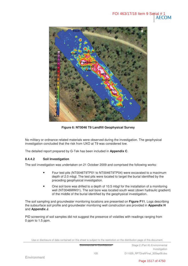
Use or disclosure of data contained on this sheet is subject to the restriction on the distribution page of this document.
Commercial in Confidence Stage 2 (Part III) Environmental
Investigation
105 D11029_RPTDraftFinal_30Sep09.doc
Figure 6: NT0046 T9 Landfill Geophysical Survey
No military or ordnance related materials were observed during the investigation. The geophysical investigation concluded that the risk from UXO at T9 was considered low.
The detailed report prepared by G-Tek has been included in Appendix C.
8.4.4.2 Soil Investigation
The soil investigation was undertaken on 21 October 2009 and comprised the following works:
• Four test pits (NT0046T9TP01 to NT0046T9TP04) were excavated to a maximum depth of 2.0 mbgl. The test pits were located to target the burial identified by the preceding geophysical investigation.
• One soil bore was drilled to a depth of 10.5 mbgl for the installation of a monitoring well (NT0046MW01). The soil bore was located south west (down hydraulic gradient) of the middle of the burial identified by the geophysical investigation.
The soil sampling and groundwater monitoring locations are presented on Figure F11. Logs describing the subsurface soil profile and groundwater monitoring well construction are provided in Appendix H and Appendix J.
PID screening of soil samples did not suggest the presence of volatiles with readings ranging from 0 ppm to 1.5 ppm.
FOI 463/17/18 Item 9 Serial # 1
Page 1517 of 4750
Use or disclosure of data contained on this sheet is subject to the restriction on the distribution page of this document.
Commercial in Confidence Stage 2 (Part III) Environmental
Investigation
106 D11029_RPTDraftFinal_30Sep09.doc
Fill Material
Shallow surface fill materials were encountered across the centre of the area (test pits NT0046T09TP02 to NT0046T9TP04) to a depth of 0.5 mbgl, overlying natural clay and silt units. The fill material principally comprised grey brown clayey sandy silt, with some building and general waste, and traces of ash. The fill was thickest at the centre of the area and tapered to nothing towards the boundary of the clearing. Investigation locations NT0046T09TP01 and NT0046MW01 defined east and south west extent of the fill material.
Localised collections of building demolition rubble (reinforced concrete, metal cable) and general waste (metal drums, 1970s soft drink cans and plastic) were encountered within the fill across the landfill site. Dumped car parts and barbed wire were observed at the surface on the western end of the site (refer to Figure 6).
A 205 L drum (no lid and empty) was located in a nearby erosion gully on the south eastern side of T9 (Plate 28). There was also a pile of 20 L drums (possibly former cooking oil containers) located north of the area.
Natural Soil and Rock
The stratigraphy encountered by the test pit and drilling investigation comprised of surficial fill units (as described above) to maximum 0.5 mbgl, overlying orange brown silty clay/clayey silt to approximately 1.5 mbgl, grading to limestone gravels, cobbles and boulders in a clay matrix at greater depth. Test pit excavations were generally terminated in limestone boulders between 1.5 mbgl and 2 mbgl. Limestone gravels, cobbles and boulders were encountered at shallower depths (0.5 mbgl in NT0046MW01) to the south of the landfill clearing.
Rock was encountered at 4.7 mbgl during the drilling of NT0046MW01, comprising brown orange mudstone/siltstone of 2 m thickness, overlying a moderately weathered and porous limestone.
8.4.4.3 Groundwater Investigation
The groundwater investigation was undertaken on 10 November 2008. One groundwater sample was collected from the newly installed monitoring well NT0046MW01.
As described above, NT0046MW01 was installed down hydraulic gradient of the landfill clearing. Groundwater inflow was encountered at 8.5 mbgl within porous limestone bedrock. The standing water level measured a week after well installation and development was 5.23 m BTOC.
Rapid groundwater inflow was noted from within the weathered limestone horizon intersected by the monitoring well. Groundwater encountered during drilling of NT0046MW01 had an odour above the observed water inflow at 8.5 mbgl. This odour was not evident at greater depths. PID screening of the drill cuttings did not indicate the presence of volatiles (all results < 0.2 ppm).
8.5 Laboratory Analytical Results
8.5.1 Soil Analysis
The soil samples from NT0046 were analysed for a range of CoPC including metals (NEPM 13 – As, Be, Ba, Cd, Cu, Co, Pb, Mn, Hg, Ni, V, Zn), TPH, PAHs, MAH, VOC, SVOC, ammonia, nitrates, nitrites and asbestos.
The results of the soil sample laboratory analysis compared against the assessment criteria are summarised in Table T1. Laboratory analytical reports are provided in Appendix I.
FOI 463/17/18 Item 9 Serial # 1
Page 1518 of 4750
Use or disclosure of data contained on this sheet is subject to the restriction on the distribution page of this document.
Commercial in Confidence Stage 2 (Part III) Environmental
Investigation
107 D11029_RPTDraftFinal_30Sep09.doc
Metals
Forty-two soil samples were analysed for metals. All sample concentrations were reported below NEPM HILF. However, exceedances of the laboratory LOR and/or NEPM EILs where recorded for the following analytes:
• Vanadium concentrations above the laboratory LOR were recorded in all samples. Twenty-one (21) of the 42 samples exceeded the NEPM EIL of 50 mg/kg, with the highest concentration (148 mg/kg) measured at NT0046T9TP03 (0.4 to 0.5 m). With the exception of NT0046T9TP03 (0.4 to 0.5 m), these results were all within the background concentration ranges established for the Base.
• Zinc concentrations above the laboratory LOR were recorded in all samples. Only one of the 42 samples, NT0046T6TP01 (0.0 to 0.1 m) (295 mg/kg), exceeded the NEPM EIL of 200 mg/kg. With the exception of NT0046T6TP01 (0.0 to 0.1 m), the results were within the background concentration ranges established for the Base.
• Manganese concentrations above the LOR were recorded in all samples. Two of the 42 samples, NT0046T8TP01 (4.2 to 4.3 m) and NT0046T9TP04 (1.4 to 1.5 m), exceeded the NEPM EIL of 500 mg/kg with concentrations of 2,050 mg/kg and 659 mg/kg, respectively. With the exception of the above exceedances, the results were within the background concentration ranges established for the Base.
• Barium concentrations above the LOR were recorded in all samples. One of the 42 samples, NT0046T8TP01 (4.2 to 4.3 m) (500 mg/kg), exceeded the NEPM EIL of the 300 mg/kg. With the exception of NT0046T8TP01 (4.2 to 4.3 m), the results were within the background concentration ranges established for the Base.
• The remaining metal analytes (i.e. arsenic, beryllium, cadmium, chromium, cobalt, copper, lead and nickel) returned concentrations either below the laboratory LOR and/or below the NEPM EIL.
TPH
Forty-two soil samples were analysed for TPH. All concentrations were reported below the laboratory LOR and the adopted guideline.
VOCs
Five soil samples (equating to approximately 10%) were analysed for Volatile Organic Compounds (VOCs). All concentrations were reported below the laboratory LOR and the adopted guideline.
Forty-two soil samples were analysed for MAH. All concentrations were reported below the laboratory LOR.
SVOCs
Five soil samples (equating to approximately 10%) were analysed for Semi-Volatile Organic Compounds (SVOC). All concentrations were reported below the laboratory LOR and the adopted guideline.
Forty-two soil samples were analysed for PAH. All concentrations were reported below the laboratory LOR and the adopted guideline.
FOI 463/17/18 Item 9 Serial # 1
Page 1519 of 4750
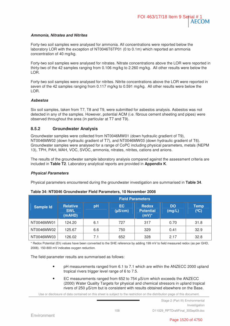
Use or disclosure of data contained on this sheet is subject to the restriction on the distribution page of this document.
Stage 2 (Part III) Environmental
Investigation
108 D11029_RPTDraftFinal_30Sep09.doc
Ammonia, Nitrates and Nitrites
Forty-two soil samples were analysed for ammonia. All concentrations were reported below the laboratory LOR with the exception of NT0046T6TP01 (0 to 0.1m) which reported an ammonia concentration of 40 mg/kg.
Forty-two soil samples were analysed for nitrates. Nitrate concentrations above the LOR were reported in thirty-two of the 42 samples ranging from 0.106 mg/kg to 2.260 mg/kg. All other results were below the LOR.
Forty-two soil samples were analysed for nitrites. Nitrite concentrations above the LOR were reported in seven of the 42 samples ranging from 0.117 mg/kg to 0.591 mg/kg. All other results were below the LOR.
Asbestos
Six soil samples, taken from T7, T8 and T9, were submitted for asbestos analysis. Asbestos was not detected in any of the samples. However, potential ACM (i.e. fibrous cement sheeting and pipes) were observed throughout the area (in particular at T7 and T9).
8.5.2 Groundwater Analysis
Groundwater samples were collected from NT0046MW01 (down hydraulic gradient of T9), NT0046MW02 (down hydraulic gradient of T7), and NT0046MW03 (down hydraulic gradient of T6). Groundwater samples were analysed for a range of CoPC including physical parameters, metals (NEPM 13), TPH, PAH, MAH, VOC, SVOC, ammonia, nitrates, nitrites, cations and anions.
The results of the groundwater sample laboratory analysis compared against the assessment criteria are included in Table T2. Laboratory analytical reports are provided in Appendix K.
Physical Parameters
Physical parameters encountered during the groundwater investigation are summarised in Table 34.
Table 34: NT0046 Groundwater Field Parameters, 10 November 2008
Field Parameters
Sample Id Relative SWL
(mAHD)
pH EC (μS/cm)
Redox Potential
(mV)*
DO (mg/L)
Temp (ºC)
NT0046MW01 124.20 6.1 727 317 0.70 31.8
NT0046MW02 125.67 6.6 750 329 0.41 32.9
NT0046MW03 126.02 7.1 652 328 2.17 32.8
* Redox Potential (Eh) values have been converted to the SHE reference by adding 199 mV to field measured redox (as per GHD,
2008). 150-800 mV indicates oxygen reduction.
The field parameter results are summarised as follows:
• pH measurements ranged from 6.1 to 7.1 which are within the ANZECC 2000 upland tropical rivers trigger level range of 6 to 7.5.
• EC measurements ranged from 652 to 754 μS/cm which exceeds the ANZECC (2000) Water Quality Targets for physical and chemical stressors in upland tropical rivers of 250 S/cm but is consistent with results obtained elsewhere on the Base.
FOI 463/17/18 Item 9 Serial # 1
Page 1520 of 4750
Use or disclosure of data contained on this sheet is subject to the restriction on the distribution page of this document.
Commercial in Confidence Stage 2 (Part III) Environmental
Investigation
109 D11029_RPTDraftFinal_30Sep09.doc
• DO measurements indicate low to moderate oxygen levels in the groundwater.
• Redox potential measurements ranged between 317 and 329 mV, indicating water is aerobic in nature.
Inferred Groundwater Contour
Based on the standing water levels measured in the groundwater monitoring wells associated with NT0046, groundwater was inferred to be flowing in a westerly direction, towards Tindal Creek (refer Figure F6).
Nutrients
Nutrients concentrations encountered during the groundwater investigation have been summarised below:
• Ammonia as N concentrations ranged from <0.01 mg/L in NT0046MW02 and NT0046MW03 to 0.03 mg/L in NT0046MW01, all of which are below the ANZECC 95% protection trigger level of 0.9 mg/L.
• Nitrate concentrations ranged from 0.04 mg/L at NT0046MW01, 0.29 mg/L at NT0046MW02 to 0.32 mg/L at NT0046MW03, all of which are below the ANZECC 95% protection trigger level of 0.7 mg/L and the ADWG 2004 guideline of 50 mg/L.
• Nitrite concentrations ranged from 0.01 mg/L at NT0046MW01 and NT0046MW02 to NT0046MW03 (<0.01 mg/L), all of which are below the ADWG 2004 guideline of 3 mg/L.
• Total oxidised nitrogen (NOx) concentrations ranged from 0.05 mg/L at NT0046MW01, 0.3 mg/L at NT0046MW02 to 0.32 mg/L at NT0046MW03, all of which are above the ANZECC (2000) Water Quality Targets for physical and chemical stressors of 0.01 mg/L.
Major Ions
Concentrations of major ions reported during the groundwater investigation have been summarised below. All results were within the ANZECC 2000 stock water quality guidelines, where applicable.
• Total anion concentrations ranged from 0.94 meq/L at NT0046MW01, 0.99 meq/L at NT0046MW02 to 0.96 meq/L at NT0046MW03.
- Total alkalinity as CaCO3 concentrations ranged from 2 mg/L at NT0046MW01 and NT0046MW03 to 4 mg/L at NT0046MW02.
- Chloride concentrations were 30 mg/L at NT0046MW01, NT0046MW02 and NT0046MW03.
- Sulfate as SO42- concentrations ranged from 3 mg/L at NT0046MW01 and
NT0046MW02 to 4 mg/L in NT0046MW03, both of which are below the NHMRC drinking water guidelines of 500 mg/L.
• Total cation concentrations ranged from 0.88 mg/L at NT0046MW01, 1.04 mg/L at NT0046MW02 to 1.05 mg/L at NT0046MW03. While the site assessment criteria do not include guidelines for major cations, the reported concentrations (as follows) were within the ANZECC (2000) stock water quality guidelines.
- Calcium (Ca) concentration was reported at 30 mg/L in the three monitoring wells.
FOI 463/17/18 Item 9 Serial # 1
Page 1521 of 4750
Use or disclosure of data contained on this sheet is subject to the restriction on the distribution page of this document.
Commercial in Confidence Stage 2 (Part III) Environmental
Investigation
110 D11029_RPTDraftFinal_30Sep09.doc
- Magnesium (Mg) concentrations ranged from 6 mg/L at NT0046MW01 to 8 mg/L at NT0046MW02 and NT0046MW03.
- Sodium (Na) concentrations ranged from 2 mg/L at NT0046MW01 and NT0046MW03 to 4 mg/L at NT0046MW02.
- Potassium (K) concentrations ranged from 2 mg/L at NT0046MW02 to 4 mg/L at NT0046MW01 and NT0046MW03.
Metals
The groundwater samples collected from the three wells reported dissolved concentrations of metals less than the ANZECC 95% protection level trigger values for freshwater ecosystems and the NHMRC (2004) Australian Drinking Water – Health guidelines, with the following exceptions:
• Copper – concentrations reported at NT0046MW01 (0.002 mg/L), NT0046MW02 (0.003 mg/L) and NT0046MW03 (0.003 mg/L), exceeded the ANZECC 95% protection trigger level of 0.0014 mg/L but were below the NHMRC (2004) Australian Drinking Water – Health of 2 mg/L. All results were within the background concentration ranges established for the Base.
• Nickel – concentrations reported at NT0046MW01 (0.03 mg/L), NT0046MW02 (0.02 mg/L) and NT0046MW03 (0.024 mg/L) exceeded the ANZECC 95% protection trigger level of 0.011 mg/L and equalled/exceeded the NHMRC health drinking water guideline of 0.02 mg/L. Concentrations slightly exceeded the background concentration ranges established for the Base.
• Vanadium – concentration reported at NT0046MW02 (0.02 mg/L) exceeded the ANZECC 95% protection (low reliability) trigger level of 0.006 mg/L and the background concentration ranges established for the Base.
• Zinc – concentrations reported NT0046MW01 (0.011 mg/L) exceeded the ANZECC 95% protection trigger level of 0.008 mg/L, but were below the NHMRC health drinking water guideline of 3 mg/L. All results were within the background concentration ranges established for the Base.
TPH
The groundwater samples collected from the three wells were analysed for TPH. All concentrations were reported below the laboratory LOR.
VOCs
The groundwater samples collected from the three wells were analysed for VOCs. All concentrations were reported below the laboratory LOR.
The groundwater samples collected from the three wells were analysed for MAH. All concentrations were reported below the laboratory LOR.
SVOCs
The groundwater samples collected from the three wells were analysed for SVOCs. All concentrations were reported below the laboratory LOR.
The groundwater samples collected from the three wells were analysed for PAH. All concentrations were reported below the laboratory LOR.
FOI 463/17/18 Item 9 Serial # 1
Page 1522 of 4750

Use or disclosure of data contained on this sheet is subject to the restriction on the distribution page of this document.
Commercial in Confidence Stage 2 (Part III) Environmental
Investigation
111 D11029_RPTDraftFinal_30Sep09.doc
8.6 Discussion of Site Contamination Issues
8.6.1 Contained Waste
Based on geophysical and intrusive (test pitting) an investigation at NT0046, buried waste was identified at T7 and T9 only. The footprints (exclusive of scattered surface waste) are estimated as follows:
• Landfill T7 – 1,500 m2 with an estimated contained waste volume of 3,000 m3, based on a maximum depth of fill to 2.0 mbgl.
• Landfill T9 – 2,600 m2 with an estimated contained waste volume of 1,300 m3, based on a maximum depth of fill to 0.5 mbgl.
The waste contained by T7 landfill is broadly characterised as potential ACM and metal fragments, including a large number of 205 L steel drums. The drums where flattened, had no lids and did not appear to contain any liquids.
The waste contained by T9 landfill is broadly characterised as localised clusters of building demolition rubble (reinforced concrete, metal cable, potential ACM) and general waste (metal drums, 1970s soft drink cans and plastic material). The waste was encountered both at the near surface and depth, across the landfill footprint. Dumped car parts, barbed metal wire and drums were also observed at the surface of the landfill and adjacent bushland.
Scattered surface debris including 20 L and 205 L rusted drums (contents unknown), scrap metal ropes, star pickets, razor wire and barb wire, potential ACM, etc., were observed across the NT0046 landfill footprint.
T6 was not found to contain any buried waste. The area incorporated three man-made ponds, joined by pipes, which are suspected to represent the original sewage treatment ponds for the Base.
No military or ordnance related materials were observed during the investigation. The geophysical investigation concluded that the risk from UXO at NT0046 was considered low.
8.6.2 Soil Contamination
The soil analysis results from NT0046 were within the NEPM HILF for industrial/commercial land use. A number of sample analysis results contained metals concentration, including vanadium, zinc, manganese and barium, which exceed the NEPM EIL. These results were generally consistent with the background concentrations established for the Base. Notwithstanding, it is possible that some impact may be the result of the scrap metal identified within the landfills.
Asbestos contamination was not reported by the soil samples collected as part of the investigation. However, potential ACM (i.e. fibrous cement sheeting and pipes) were observed throughout the area (in particular at T7 and T9). The historical information for the Base identified that the majority of construction at RAAF Tindal occurred during the 1950s to 1970s, when asbestos was commonly used for building products. As such, the buried building materials identified during the Stage 2 (III) have the potential to contain asbestos.
8.6.3 Groundwater Contamination
In general, the analysis results from the groundwater samples collected from the three wells down-hydraulic gradient of the NT0046 landfill footprints were less than the adopted site assessment criteria. The only exceptions to this were as follows:
• The results of the groundwater monitoring program did not indicate that the odours observed during drilling were attributable to the presence of volatiles.
FOI 463/17/18 Item 9 Serial # 1
Page 1523 of 4750
Use or disclosure of data contained on this sheet is subject to the restriction on the distribution page of this document.
Commercial in Confidence Stage 2 (Part III) Environmental
Investigation
112 D11029_RPTDraftFinal_30Sep09.doc
• Concentrations of copper, nickel, vanadium and zinc within the groundwater, located down-hydraulic gradient, which exceeded the ANZECC 95% protection trigger values.
These concentrations are generally consistent with background levels returned within other monitoring wells located across RAAF Tindal. However, concentrations of copper and zinc may also potentially be attributed to leaching from the anthropogenic activity within the area, including leaching from the scrap metal and drums observed within T7 and T9 landfill areas or from historical site uses (e.g. STP) at T6.
• Electrical conductivity measurements exceeded the ANZECC (2000) Water Quality Targets for physical and chemical stressors in upland tropical rivers of 250 S/cm, with results ranging from 652 to 750 μS/cm. These measurements are generally consistent with levels reported for other areas across the Base (GHD, 2008).
• Concentrations of nitrogen exceeded the ANZECC (2000) Water Quality Targets for physical and chemical stressors of 0.01 mg/L at the three monitoring locations. Results recorded at other locations across the Base (i.e. NT0049MW02) indicate that nutrients are naturally occurring within the groundwater beneath RAAF Tindal.
The NT0046 aquifer is present within karstic limestone, which was not encountered at other locations. These sites are generally down hydraulic gradient of the airfield. The ionic distribution and the presence of cavities in the limestone suggested the aquifer underlying NT0046 may be only partially connected to the aquifer underlying the central, eastern south-eastern portions of the site.
8.7 Summary and Recommendations
8.7.1 Nature and Extent of Contamination
The findings of the Stage 2 (III) Investigations at NT0046 are as follows:
• Number of contaminated areas investigated: A total of four areas were investigated at NT0046 – T6, T7, T8 and T9. T7 and T9 were the only sites to show evidence of landfill.
• Chemical contamination: No explosive residues or UXOs were detected during the intrusive investigation or the proceeding geophysical investigation. Potential ACM were visually noted across the area. Buried waste was identified specifically within T7 and T9.
• Chemicals of Concern:
- ACM.
• Buried Waste:
- Miscellaneous waste materials, including 20 L and 205 L rusted drums (contents unknown), scrap metal ropes, star pickets, razor wire and barb wire, ACM, etc., were observed to be scattered across the surface throughout NT0046.
- Buried waste within the T7 landfill was identified over an area of 1,500 m2 with an estimated volume of 3,000 m3, based on a maximum depth of fill to 2.0 mbgl.
- Buried waste within the T9 landfill was identified over any are of 2,600 m2 with an estimated volume of 1,300 m3, based on a maximum depth of fill to 0.5 mbgl.
FOI 463/17/18 Item 9 Serial # 1
Page 1524 of 4750
Use or disclosure of data contained on this sheet is subject to the restriction on the distribution page of this document.
Commercial in Confidence Stage 2 (Part III) Environmental
Investigation
113 D11029_RPTDraftFinal_30Sep09.doc
• Soil Investigations:
- Contaminant concentrations identified in the soil are not expected to pose an adverse impact to human health and are considered to be acceptable for continuing commercial/industrial land use.
- Elevated heavy metal concentrations were reported at a number of locations (specifically vanadium, zinc, manganese and barium), which exceed the ANZECC EIL, but were less than the NEPM HILF and generally consistent with the background concentrations for the Base.
- All other soil concentrations were reported below the NEPM HILF and EILs.
- Asbestos contamination was not detected within the soil samples; however, the presence of asbestos cannot be discounted because potential ACM (i.e. fibrous cement sheeting fragments and pipes) were observed throughout the landfill areas (T7 and T9 in particular) and across the surface of NT0046 in general.
• Groundwater Investigation:
- Contaminant concentrations identified in groundwater are not expected to pose an adverse impact to human health and are considered to be acceptable for continuing commercial/industrial land use.
- Copper, nickel, vanadium and zinc were reported at concentrations which exceeded the ANZECC 95% protection trigger levels but were generally consistent with background levels at the Base.
- EC measurements exceeded the ANZECC (2000) Water Quality Targets for physical and chemical stressors in upland tropical rivers but were consistent with levels reported for other groundwater monitoring events at the Base (GHD, 2008).
- Nitrogen (NOx) exceeded the ANZECC (2000) Water Quality Targets for physical and chemical stressors but was consistent with the results recorded at other locations across the Base (i.e. NT0049MW02 – up gradient) indicating that nutrient concentrations are naturally high within the groundwater at the Base.
- Nitrate concentrations were below the ANZECC 95% protection trigger level of 0.7 mg/L and the ADWG 2004 guideline of 50 mg/L.
- All other groundwater concentrations were reported below ANZECC 2000 trigger levels.
• Contaminant Migration: In general, the investigation found that contaminants, where present, were largely confined to the extent of the contamination source.
8.7.2 Risks Identified
Appendix L summarises the assessment of risks associated with the identified contamination at NT0046. The results of the Stage 2 (III) risk assessment are summarised as follows:
• NT0046 T6 – High Risk Band with a Risk Priority score of 179 based on presence of potential ACM at the surface where human contact is possible (OHS dimension).
• NT0046 T7 – High Risk Band with a Risk Priority score of 168 based on exposure of contractors to potential ACM if conducting intrusive works (OHS dimension) and human contact from potential exposure to surface ACM. In addition, a Medium Risk Band with a Risk Priority score of 177 based on the potential for Defence personnel
FOI 463/17/18 Item 9 Serial # 1
Page 1525 of 4750
Use or disclosure of data contained on this sheet is subject to the restriction on the distribution page of this document.
Commercial in Confidence Stage 2 (Part III) Environmental
Investigation
114 D11029_RPTDraftFinal_30Sep09.doc
and contractors to have contact with landfill objects including star pickets, drums, wire etc. exposed at the surface (i.e. OHS dimension).
• NT0046 T8 – Low Risk Band with a Risk Priority score of 191 based on no significant finds at the site.
• NT0046 T9 – High Risk Band with a Risk Priority score of 168 based on the exposure of contractors to potential ACM if conducting intrusive works (OHS dimension) and human contact from potential exposure to surface ACM. In addition, a Medium Risk Band with a Risk Priority score of 177 based on the potential for Defence personnel and contractors to have contact with landfill objects including star pickets, drums, wire etc. exposed at the surface (i.e. OHS dimension).
8.7.3 Site Specific Recommendations
NT0046 T6 and T9 are located within the RAAF Tindal security fence and T7 and T8 are located just outside the fence. Public access to the areas inside the fence is extremely unlikely. Public access to those areas outside the fence is possible, although also considered unlikely. Defence training activities, area maintenance (i.e. slashing) and/or site redevelopment, may result in Defence personnel and contractors accessing these areas. As such, the following recommendations have been made in relation to NT0046:
• Erect signage and fence the buried waste landfill footprints (T7 and T9) using a stock fence to restrict access (without drawing undue attention to the areas outside the perimeter fence, as may be the case if a chain link fence was erected.
• Erect signage identifying general risk associated with the landfill areas.
• Include NT0046 area of interest on the CEMP (developed by AECOM as part of the Stage 2 (III) Investigations) and the Base Asbestos Register.
• Further assess the significance of the ACM surface contamination against the WA DOH guidelines (2009). If the ACM surface contamination exceeds the WA DOH guidelines:
- Remove suspected ACM from the landfill surface and immediate surrounds by ‘Emu Pick’ (manual collection), completed by an appropriately licensed contractor.
- Dispose of ACM to an offsite licensed facility (Darwin City Council Shoal Bay Waste Disposal Site (Licence No. 12).
• Consider the removal of waste (i.e. drums, portable runways etc.) scattered over the surface of NT0046 footprint to reduce the risk of negative impact to the visual amenity of the area and risk to human health and safety (e.g. star pickets, razor wire etc. at the surface).
FOI 463/17/18 Item 9 Serial # 1
Page 1526 of 4750
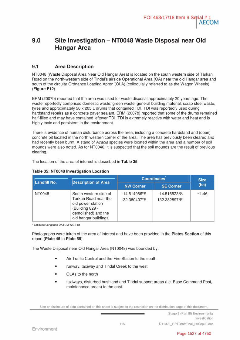
Use or disclosure of data contained on this sheet is subject to the restriction on the distribution page of this document.
Stage 2 (Part III) Environmental
Investigation
115 D11029_RPTDraftFinal_30Sep09.doc
9.0 Site Investigation – NT0048 Waste Disposal near Old Hangar Area
9.1 Area Description
NT0048 (Waste Disposal Area Near Old Hangar Area) is located on the south western side of Tarkan Road on the north-western side of Tindal’s airside Operational Area (OA) near the old Hangar area and south of the circular Ordnance Loading Apron (OLA) (colloquially referred to as the Wagon Wheels) (Figure F12).
ERM (2007b) reported that the area was used for waste disposal approximately 20 years ago. The waste reportedly comprised domestic waste, green waste, general building material, scrap steel waste, tyres and approximately 50 x 205 L drums that contained TDI. TDI was reportedly used during hardstand repairs as a concrete paver sealant. ERM (2007b) reported that some of the drums remained half-filled and may have contained leftover TDI. TDI is extremely reactive with water and heat and is highly toxic and persistent in the environment.
There is evidence of human disturbance across the area, including a concrete hardstand and (open) concrete pit located in the north western corner of the area. The area has previously been cleared and had recently been burnt. A stand of Acacia species were located within the area and a number of soil mounds were also noted. As for NT0046, it is suspected that the soil mounds are the result of previous clearing.
The location of the area of interest is described in Table 35.
Table 35: NT0048 Investigation Location
Coordinates*
Landfill No. Description of Area NW Corner SE Corner
Size (ha)
NT0048 South western side of Tarkan Road near the old power station (Building 829 - demolished) and the old hangar buildings.
-14.514986ºS
132.380407ºE
-14.516523ºS
132.382897ºE
~1.46
* Latidude/Longitude DATUM WGS 84
Photographs were taken of the area of interest and have been provided in the Plates Section of this report (Plate 45 to Plate 59).
The Waste Disposal near Old Hangar Area (NT0048) was bounded by:
• Air Traffic Control and the Fire Station to the south
• runway, taxiway and Tindal Creek to the west
• OLAs to the north
• taxiways, disturbed bushland and Tindal support areas (i.e. Base Command Post, maintenance areas) to the east.
FOI 463/17/18 Item 9 Serial # 1
Page 1527 of 4750

Use or disclosure of data contained on this sheet is subject to the restriction on the distribution page of this document.
Commercial in Confidence Stage 2 (Part III) Environmental
Investigation
116 D11029_RPTDraftFinal_30Sep09.doc
9.2 Objectives
To meet the overall objective of the Stage 2 (III) Investigation of defining the ‘true risks’ to Defence of potential contamination, NT0048 (Waste Disposal Near Old Hangar Area) were investigated to:
• delineate the vertical and lateral extent of landfill material and chemical contamination (to the extent practical)
• quantify and characterise waste material within landfill
• identify potential human health and ecological receptors
• assess the potential for waste materials and/or impacted soils to leach contaminants of concern into groundwater and receiving waters.
9.3 Historical Information, Previous Investigations and Potential Chemicals of Concern
9.3.1 Previous Reports
The Landfill/Burial Sites Stage 1 Environmental Investigation (Stage 1 EI) prepared by ERM (2007b) included an assessment of the status of NT0048 (Waste Disposal Near Old Hangar Area).
The Stage 1 EI (ERM, 2007b) reported that the disposal area was used approximately 20 years ago and was associated with the disposal of domestic waste, green waste, general building material, scrap steel waste, tyres and approximately 50 x 205 L drums reported to contain TDI. Visual observations also suggested that the areas were no longer used for waste disposal.
The Stage 1 EI concluded that NT0048 posed a high risk based on human exposure to contaminated soil.
The recommendations in the Stage 1 EI were:
• fencing of the area
• conduct a geophysics investigation
• soil investigation
• groundwater monitoring
• remediation/capping.
9.3.2 Historical Aerial Photographs
A limited review of the available historical aerial photographs at the office of DS-Tindal was undertaken during the Stage 2 (III) Investigations for the NT0048 landfill to assist in identifying the investigation areas.
Limited information was able to be obtained from these aerials.
9.3.3 Potential Chemicals of Concern
Based on the available historical information, the potential chemicals of concern determined for the Stage 2 (III) Investigations at NT0048 include:
• heavy metals (i.e. arsenic, copper, cadmium, lead, mercury, nickel, tin and zinc)
FOI 463/17/18 Item 9 Serial # 1
Page 1528 of 4750
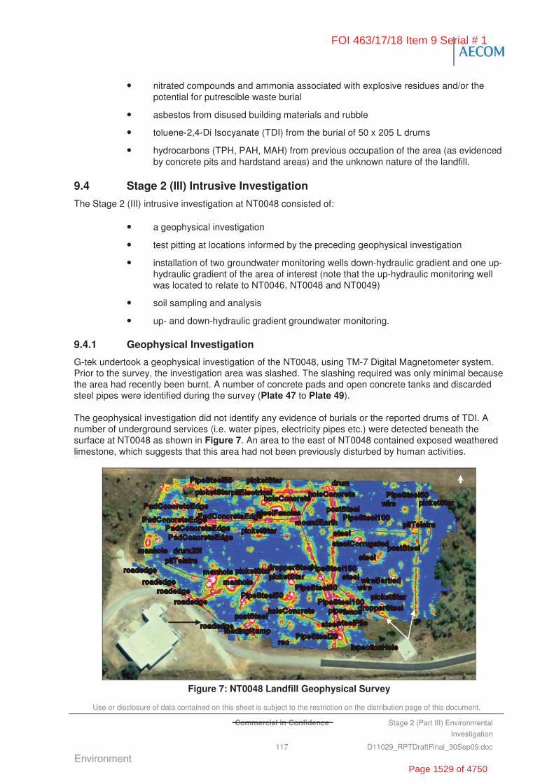
Use or disclosure of data contained on this sheet is subject to the restriction on the distribution page of this document.
Commercial in Confidence Stage 2 (Part III) Environmental
Investigation
117 D11029_RPTDraftFinal_30Sep09.doc
• nitrated compounds and ammonia associated with explosive residues and/or the potential for putrescible waste burial
• asbestos from disused building materials and rubble
• toluene-2,4-Di Isocyanate (TDI) from the burial of 50 x 205 L drums
• hydrocarbons (TPH, PAH, MAH) from previous occupation of the area (as evidenced by concrete pits and hardstand areas) and the unknown nature of the landfill.
9.4 Stage 2 (III) Intrusive Investigation
The Stage 2 (III) intrusive investigation at NT0048 consisted of:
• a geophysical investigation
• test pitting at locations informed by the preceding geophysical investigation
• installation of two groundwater monitoring wells down-hydraulic gradient and one up-hydraulic gradient of the area of interest (note that the up-hydraulic monitoring well was located to relate to NT0046, NT0048 and NT0049)
• soil sampling and analysis
• up- and down-hydraulic gradient groundwater monitoring.
9.4.1 Geophysical Investigation
G-tek undertook a geophysical investigation of the NT0048, using TM-7 Digital Magnetometer system. Prior to the survey, the investigation area was slashed. The slashing required was only minimal because the area had recently been burnt. A number of concrete pads and open concrete tanks and discarded steel pipes were identified during the survey (Plate 47 to Plate 49).
The geophysical investigation did not identify any evidence of burials or the reported drums of TDI. A number of underground services (i.e. water pipes, electricity pipes etc.) were detected beneath the surface at NT0048 as shown in Figure 7. An area to the east of NT0048 contained exposed weathered limestone, which suggests that this area had not been previously disturbed by human activities.
Figure 7: NT0048 Landfill Geophysical Survey
FOI 463/17/18 Item 9 Serial # 1
Page 1529 of 4750

Use or disclosure of data contained on this sheet is subject to the restriction on the distribution page of this document.
Commercial in Confidence Stage 2 (Part III) Environmental
Investigation
118 D11029_RPTDraftFinal_30Sep09.doc
No military or ordnance related materials were observed during the investigation. The geophysical investigation concluded that the risk from UXO at NT0048 was considered low.
The detailed report prepared by G-Tek has been included in Appendix C.
9.4.2 Soil Investigation
The soil investigation was undertaken on 23 and 24 October 2008 and comprised the following works:
• Five test pits (NT0048TP01 to NT0048TP05) were excavated to a maximum depth of 3.3 mbgl. The test pits were located to target below the pipelines and anomalies. NT0048TP03 was used as a background sample.
• Two soil bores were drilled to a depth of 10.50 mbgl (NT0048MW02) and 13.39 mbgl (NT0048MW01) for the installation of monitoring wells down-hydraulic gradient of the area of interest.
• One soil bore was drilled to a depth of 12.62 mbgl for the installation of a monitoring well up-hydraulic gradient of the area of interest. The location of this well was selected to provide an up-hydraulic gradient reference for NT0049, NT0046 and NT0065 in addition to NT0048. The installation of this monitoring well is reported as part of NT0049 (refer to Section 10.0).
The soil sampling and groundwater monitoring locations are presented on Figure F13. Logs describing the subsurface soil profile and groundwater monitoring well construction are provided in Appendix H and Appendix J.
Fill Material
Reworked natural material, consisting of red brown silty clay, was encountered overlying historical and current service lines. On the eastern end of the investigation area, a white (suspected water) pipe was uncovered by test pit NT0048TP05.
PID screening of all potential fill samples did not suggest the presence of volatiles with PID readings ranging from 0.9 ppm to 1.1 ppm.
Natural Soil and Rock
The stratigraphy encountered comprised of red brown and orange clays and silts at the surface, overlying yellow brown clayey silts, especially on the southern and western portion of the site (NT0048MW02, NT0048TP05 and NT0048TP01). Limestone gravels, cobbles and boulders were encountered at depth, which resulted in test pit excavations reaching refusal at between 1.1 mbgl and 3.3 mbgl. No evidence of shallow limestone was encountered during the intrusive investigations at NT0048.
Rock encountered during the drilling investigation consisted of well consolidated limestone at approximately 5.5 mbgl on the western portion of the site (NT0048MW01) and 8.0 mbgl on the southern portion of the site (NT0048MW02).
PID screening of soil samples did not suggest the presence of volatiles with PID readings ranging from 0 to 1.3 ppm.
9.4.2.1 Groundwater Investigation
The groundwater investigation was undertaken on 6 November 2008. Three groundwater samples were collected from the newly installed monitoring wells NT0048MW01, NT0048MW02 and NT0049MW02.
FOI 463/17/18 Item 9 Serial # 1
Page 1530 of 4750
Use or disclosure of data contained on this sheet is subject to the restriction on the distribution page of this document.
Commercial in Confidence Stage 2 (Part III) Environmental
Investigation
119 D11029_RPTDraftFinal_30Sep09.doc
Groundwater inflow was encountered within the limestone bedrock at 11.0 mbgl at NT0048MW01 and 8.5 mbgl at NT0048MW02. The standing water level measured a week after installation and development of the wells were 4.73 mbgl at NT0048MW01 and 4.01 mbgl at NT0048MW02.
Groundwater was observed to rapidly enter the open hole once the aquifer within the limestone horizon had been intersected during drilling of wells NT0048MW01 and NT0048MW02. This suggests that groundwater within the underlying limestone is confined to some degree.
9.5 Laboratory Analytical Results
9.5.1 Soil Analysis
The soil samples from NT0048 were analysed for a range of CoPC including metals (NEPM 13), TDI, TPH, PAHs, MAH, VOC, SVOC, ammonia and asbestos.
The results of the soil sample laboratory analysis compared against the assessment criteria are summarised included in Table T3. Laboratory analytical reports are provided in Appendix I. Figure F13 illustrates soil sample locations.
Metals
Fourteen soil samples were analysed for metals. All sample concentrations were reported below NEPM HILF. Exceedances of the laboratory LOR and/or NEPM EILs where recorded for the following analytes:
• Vanadium concentrations above the laboratory LOR and the NEPM EIL of 50 mg/kg were reported in all samples (with the exception of NT0048TP04 (0.9-1.0m)) with reported concentrations ranging from 14 mg/kg to 98 mg/kg. All the results were within the background concentration range established for the Base.
• Manganese concentrations above the laboratory LOR were reported in all samples. Seven of the 14 samples exceeded the NEPM EIL criteria of 500 mg/kg, with the highest concentration (4,530 mg/kg) measured at NT0048TP05 (1.9 to 2.0 m). With the exception of NT0048TP05 (1.9 to 2.0 m), all the results were within the background concentration range established for the Base.
• Barium concentrations above the LOR were recorded in the majority of samples. Two of the 14 samples exceeded the NEPM EIL criteria of 300 mg/kg with the highest concentration (360 mg/kg) measured at NT0048TP05 (2.9 to 3.0 mg/kg). With the exception of the two samples which exceeded the NEPM EIL, all results were within the background concentration ranges established for the Base.
• The remaining metal and metalloid analytes (i.e. arsenic, beryllium, cadmium, chromium, cobalt, copper, lead, nickel and zinc) returned concentrations either below the laboratory LOR or below the NEPM EIL.
TDI
Fourteen soil samples were analysed for TDI. All concentrations were reported below the laboratory LOR of 1.0 μg/L and the adopted site criteria.
TPH
Fourteen soil samples were analysed for TPH. All concentrations were reported below the laboratory LOR and the adopted site criteria.
FOI 463/17/18 Item 9 Serial # 1
Page 1531 of 4750

Use or disclosure of data contained on this sheet is subject to the restriction on the distribution page of this document.
Commercial in Confidence Stage 2 (Part III) Environmental
Investigation
120 D11029_RPTDraftFinal_30Sep09.doc
VOCs
Two soil samples (equating to approximately 10%) were analysed for VOCs. All concentrations were reported below the laboratory LOR and the adopted site criteria.
Fourteen soil samples were analysed for MAH. All concentrations were reported below the laboratory LOR and the adopted site criteria.
SVOCs
Two soil samples (equating to approximately 10%) were analysed for SVOCs. All concentrations were reported below the laboratory LOR and the adopted site criteria.
Fourteen soil samples were analysed for PAH. All concentrations were reported below the laboratory LOR and the adopted site criteria.
Ammonia
Fourteen soil samples were analysed for ammonia. All concentrations were reported below the laboratory LOR and the adopted site criteria.
Asbestos
Two soil samples were submitted for asbestos analysis. Asbestos fibres were not detected in the samples. No potential ACM was noted on the surface during the intrusive investigation, however, there is a possibility that some of the old underground service lines may comprise of ACM.
9.5.2 Groundwater Analysis
Groundwater samples were collected from the two down-hydraulic gradient monitoring wells NT0048MW01 (located south west of NT0048) and NT0048MW02 (south of NT0048), and one up-hydraulic gradient monitoring well, NT0049MW09. Groundwater samples were analysed for a range of CoPC including physical parameters, metals (NEPM 13), TPH, PAH, MAH, VOC, SVOC, ammonia, nitrates, nitrites, cations and anions.
The results of the groundwater sample laboratory analysis compared against the assessment criteria are included in Table T4. Laboratory analytical reports are provided in Appendix K. Figure F13 illustrates all groundwater sample locations.
Physical Parameters
Physical parameters encountered during the groundwater investigation are summarised in Table 36.
Table 36: NT0048 Groundwater Field Parameters, 6 November 2008
Field Parameters
Sample Id Relative SWL
(mAHD) pH
EC (μS/cm)
Redox Potential
(mV)
DO (mg/L)
Temp (ºC)
NT0048MW01 127.08 6.5 732 305 0.38 32.0
NT0048MW02 127.17 6.9 683 380 0.23 31.6
NT0049MW02 128.32 6.3 738 354 5.52 31.4
FOI 463/17/18 Item 9 Serial # 1
Page 1532 of 4750

Use or disclosure of data contained on this sheet is subject to the restriction on the distribution page of this document.
Commercial in Confidence Stage 2 (Part III) Environmental
Investigation
121 D11029_RPTDraftFinal_30Sep09.doc
* Redox Potential (Eh) values have been converted to the SHE reference by adding 199 mV to field measured redox (as per GHD,
2008). 150-800 mV indicates oxygen reduction.
The field parameter results are summarised as follows:
• pH measurements ranged from 6.3 to 6.9 which are within the ANZECC 2000 upland tropical rivers trigger level range of 6 to 7.5.
• EC measurements ranged from 683 to 738 μS/cm which exceeds the ANZECC (2000) Water Quality Targets for physical and chemical stressors in upland tropical rivers of 250 S/cm but is consistent with results obtained elsewhere on the Base.
• DO measurements indicate low to moderate oxygen levels in the groundwater.
• Redox potential measurements ranged between 305 and 380 mV, indicating water is aerobic in nature.
Inferred Groundwater Contour
Based on the standing water levels measured in the groundwater monitoring wells associated with NT0048, groundwater was inferred to be flowing in a westerly direction towards Tindal Creek (refer to Figure F13).
Nutrients
Nutrients concentrations encountered during the groundwater investigation have been summarised below:
• Ammonia as N concentrations ranged from <0.05 mg/L at NT0049MW02 and NT0049MW02 to 0.04 mg/L in NT0048MW01, all of which are below the ANZECC 95% protection trigger level of 0.9 mg/L.
• Nitrate concentrations ranged from 0.01 mg/L at NT0048MW01, 0.06 mg/L at NT0048MW02 and 0.20 mg/L at NT0049MW02, all of which are below the ANZECC 95% protection trigger level of 0.7 mg/L.
• Nitrite concentrations were below the LOR of <0.01 mg/L at NT0048MW01, NT0048MW02 and NT0049MW02.
• Total oxidised nitrogen (NOx) concentrations ranged from 0.1 mg/L at NT0048MW01, 0.06 mg/L at NT0048MW02 and 0.20 mg/L at NT0049MW02, all of which are above the ANZECC (2000) Water Quality Targets for physical and chemical stressors of 0.01 mg/L.
Major Ions
Concentrations of major ions encountered during the groundwater investigation have been summarised following. All results were within the ANZECC 2000 stock watering and irrigation water quality guidelines.
• Total anions (total) recorded during the groundwater investigation were 8.19 meq/L at NT0048MW01, 6.36 meq/L at NT0048MW02 and 8.94 meq/L at NT0049MW02:
- Total alkalinity as CaCO3 concentrations recorded were 316 mg/L at NT0048MW01, 302 mg/L at NT0048MW02 and 430 mg/L at NT0049MW02.
- Chloride concentrations recorded were 50 mg/L at NT0048MW01, 5 mg/L at NT0048MW02 and 3 mg/L at NT0049MW02.
FOI 463/17/18 Item 9 Serial # 1
Page 1533 of 4750

Use or disclosure of data contained on this sheet is subject to the restriction on the distribution page of this document.
Stage 2 (Part III) Environmental
Investigation
122 D11029_RPTDraftFinal_30Sep09.doc
- Sulphate as SO42- concentrations recorded were 22 mg/L at NT0048MW01,
8 mg/L at NT0048MW02 and 13 mg/L in NT0049MW02, all of which are below the NHMRC drinking water guidelines of 500 mg/L and the interim urban EIL criteria of 2,000 mg/kg.
• Total cation concentrations ranged from 7.82 meq/L at NT0048MW01, 6.86 meq/L at NT0048MW02 to 8.48 meq/L at NT0049MW02:
- Calcium concentrations recorded were 107 mg/L at NT0048MW01, 82 mg/L at NT0048MW02 and 96 mg/L at NT0049MW02.
- Magnesium concentrations recorded were 27 mg/L at NT0048MW01, 28 mg/L at NT0048MW02 and 41 mg/l at NT0049MW02.
- Sodium concentrations recorded were 5 mg/L at NT0048MW01, 10 mg/L at NT0048MW02 and 6 mg/L at NT0049MW02.
- Potassium (K) concentrations were within the laboratory LOR of 1 mg/L NT0048MW01, NT0048MW02 and NT0048MW03.
Metals
The groundwater samples collected from the three wells reported dissolved concentrations of metals less than the ANZECC 95% protection level trigger values for freshwater ecosystems and the NHMRC (2004) Australian Drinking Water – Health guidelines, with the following exceptions:
• Copper – concentrations reported at NT0048MW01 (0.002 mg/L), NT0048MW02 (0.003 mg/L) and NT0049MW02 (0.003 mg/L), exceeded the ANZECC 95% protection trigger level of 0.0014 mg/L but were below the NHMRC (2004) Australian Drinking Water – Health of 2 mg/L. All results were within the background concentration ranges established for the Base.
• Lead – concentrations reported at NT0049MW02 (0.006 mg/L) exceeded the ANZECC 95% protection trigger level of 0.0034 mg/L but was below the NHMRC (2004) Australian Drinking water – Health guideline of 0.01 mg/L and within the background concentration range established for the Base.
• Nickel – concentration reported at NT0048MW01 (0.021 mg/L) exceeded the NHMRC (2004) Australian Drinking water – Health guideline of 0.02 mg/L and NT0048MW02 (0.016 mg/L) exceeded the ANZECC 95% protection trigger level of 0.011 mg/L.
• Zinc – concentrations reported at NT0048MW02 (0.008 mg/L) and NT0049MW02 (0.012 mg/L) exceeded the ANZECC 95% protection trigger level of 0.008 mg/L, but were below the NHMRC health drinking water guideline of 3 mg/L. All results were within the background concentration ranges established for the Base.
TPH
The groundwater samples collected from the three wells were analysed for TPH. All concentrations were reported below the laboratory LOR and the adopted site criteria.
VOCs
The groundwater samples collected from the three wells were analysed for VOCs. All concentrations were reported below the laboratory LOR and the adopted site criteria.
FOI 463/17/18 Item 9 Serial # 1
Page 1534 of 4750
Use or disclosure of data contained on this sheet is subject to the restriction on the distribution page of this document.
Commercial in Confidence Stage 2 (Part III) Environmental
Investigation
123 D11029_RPTDraftFinal_30Sep09.doc
The groundwater samples collected from the three wells were analysed for MAH. All concentrations were reported below the laboratory LOR and the adopted site criteria.
SVOCs
The groundwater samples collected from the three wells were analysed for SVOCs. All concentrations were reported below the laboratory LOR and the adopted site criteria.
The groundwater samples collected from the three wells were analysed for PAH. All concentrations were reported below the laboratory LOR and the adopted site criteria.
9.6 Discussion of Site Contamination Issues
9.6.1 Contained Waste
Based on the geophysical and intrusive (test pitting) investigations at NT00048, no evidence of a historical land filling or of the reported 50 x 205 L TDI containing buried drums were identified.
There was evidence that parts of the area had been previously developed. In particular, old concrete hardstand areas and a series of concrete pits were located in the north west corner of the area and the underground service lines were identified. Base service plans from the area show only a sewage line at the eastern end of the site and a high voltage electricity on the southern portion of the site (i.e. near old power station). Therefore, it is anticipated that many of the identified services are no longer operational.
It is suspected that the open concrete pits located in the north west corner of the area may be related to septic and/or waste water (i.e. waste fuel and oil) tanks installed in association with previous activities within the area. An unknown liquid substance (i.e. most likely a rainwater mix) was noted within the concrete pits.
As such, the open pits may represent a potential source of groundwater contamination, as well as, a risk to personnel by creating and artificial breeding area for vector species (i.e. mosquitoes) and/or slip/trip hazard.
No military or ordnance related materials were observed during the investigation. The geophysical investigation concluded that the risk from UXO at NT0048 was considered low.
9.6.2 Soil Contamination
Soil analysis results from NT0048 were all below the relevant NEPM HILF guideline values for industrial/commercial land use. A number of sample analysis results contained elevated metals concentrations, including vanadium, manganese and barium, which exceeded the NEPM EIL guidelines. These results were generally recorded for samples collected at depth (i.e. greater then 1.9 mbgl) and were generally consistent with background concentrations established for the Base.
No evidence of explosives was identified in the samples.
Asbestos contamination was not reported by the soil samples collected as part of the investigation and no potential ACM was noted on the surface during the intrusive investigation. Notwithstanding, there is a possibility that some of the old underground service lines may comprise of ACM (Plate 54) and as such, if any excavations activities are to occur within the area, the operator would need to be aware of the potential risk.
FOI 463/17/18 Item 9 Serial # 1
Page 1535 of 4750

Use or disclosure of data contained on this sheet is subject to the restriction on the distribution page of this document.
Commercial in Confidence Stage 2 (Part III) Environmental
Investigation
124 D11029_RPTDraftFinal_30Sep09.doc
9.6.3 Groundwater Contamination
In general, the analysis results from the groundwater samples collected from the two wells down-hydraulic gradient of NT0048 were less than the adopted site assessment criteria. The only exceptions to this were as follows:
• Concentrations of copper, lead, nickel and zinc exceeded the ANZECC 95% protection trigger values but were generally consistent with background levels established for the Base.
• Electrical conductivity measurements exceeded the ANZECC (2000) Water Quality Targets for physical and chemical stressors in upland tropical rivers but were generally consistent with levels reported for other areas across the Base.
• Concentrations of oxidised nitrogen (NOx) exceeded the ANZECC (2000) Water Quality Targets for physical and chemical stressors but were consistent with results recorded at other locations across the Base indicating that nutrients are naturally occurring.
The groundwater quality and ionic balance reported in the two groundwater monitoring wells (NT0048MW01 and NT0048MW02) located down-hydraulic gradient of NT0048 were generally similar to those reported from the up-gradient groundwater monitoring well (NT0049MW02). This suggests that there has been little, if any, impact to groundwater quality as a result of historical activities in this area.
9.7 Summary and Recommendations
9.7.1 Nature and Extent of Contamination
The findings of the Stage 2 (III) Investigations at NT0048 are as follows:
• Chemical contamination: Chemical contamination was not identified in soil or groundwater in concentrations that exceeded the NEPM HILF for industrial/commercial land use and the ANZECC 95% protection trigger values, respectively. No asbestos, potential ACM, buried waste, explosive residues or evidence of UXOs were detected during the intrusive investigation
• Chemicals of Concern:
- Nil
• Buried Waste:
- No evidence of landfill
• Soil Investigation:
- Contaminant concentrations identified in the soil are not expected to pose an adverse human health risk and are considered to be acceptable for continuing commercial/industrial land use.
- Elevated heavy metal concentrations were reported at a number of locations (specifically vanadium, manganese and barium) which exceeded the ANZECC interim urban EIL (but were less than the NEPM HILF and generally consistent with the background concentrations determined for the Base).
- All other soil concentrations were reported below the NEPM HILF and EILs.
- Asbestos contamination was not detected within the soil samples and potential ACM was not observed on the ground surface; however, it is probable that
FOI 463/17/18 Item 9 Serial # 1
Page 1536 of 4750
Use or disclosure of data contained on this sheet is subject to the restriction on the distribution page of this document.
Commercial in Confidence Stage 2 (Part III) Environmental
Investigation
125 D11029_RPTDraftFinal_30Sep09.doc
some ACM is contained within the large number of old underground services which cross the area.
• Groundwater Investigation:
- Contaminant concentrations identified in groundwater are not expected to pose an adverse impact to human health and are considered to be acceptable for continuing commercial/industrial land use.
- Copper, lead, zinc and nickel were reported at concentrations which exceeded the ANZECC 95% protection trigger level, but were below the NHMRC (2004) Australian Drinking water-Health guideline and generally consistent with background levels.
- EC measurements exceeded the ANZECC (2000) Water Quality Targets for physical and chemical stressors in upland tropical rivers but were generally consistent with levels reported in previous groundwater monitoring events around the Base.
- Nitrogen (NOx) exceeded the ANZECC (2000) Water Quality Targets for physical and chemical stressors but were consistent with the results reported at other locations across the Base.
- All other groundwater concentrations were reported below the ANZECC 2000 trigger levels.
9.7.2 Risks Identified
Appendix L summarises the assessment of risks associated with the identified contamination at NT0048. The results of the Stage 2 (III) risk assessment are summarised following.
• NT0048 – High Risk Band with a Risk Priority score of 168 based on the potential OHS risk associated with underground services beneath the site that may contain ACM. In addition, a Medium Risk Band with a Risk Priority score of 177 based on Defence personnel and contractors being exposed to the numerous open concrete pits (possible septic or waste water tanks) located across the site.
9.7.3 Site Specific Recommendations
NT0048 is located within main OA area of RAAF Tindal. Public access to these areas are restricted, However, Defence training activities, and/or site redevelopment, may result in Defence personnel and contractors accessing these areas. As such, the following recommendations have been made in relation to NT0048:
• Fence open pits using a stock fence to minimise the risk of injury during training exercises and other activities in the area.
• Erect signage identifying the general risk associated with slip and trip hazards in the area.
• Include area as part of the CEMP (being prepared separately as part of the Stage 2 (III) Investigations.
• Include the area on the Base Asbestos Register due to the potential for unmapped buried services which may potential contain ACM.
• Consider the removal of waste (i.e. portable runways etc.) scattered over the surface of NT0048 to reduce the risk of negative impact to the visual amenity of the area and risk to human health and safety (e.g. star pickets, razor wire etc. at the surface).
FOI 463/17/18 Item 9 Serial # 1
Page 1537 of 4750

Use or disclosure of data contained on this sheet is subject to the restriction on the distribution page of this document.
Commercial in Confidence Stage 2 (Part III) Environmental
Investigation
126 D11029_RPTDraftFinal_30Sep09.doc
“This page has been left blank intentionally”
FOI 463/17/18 Item 9 Serial # 1
Page 1538 of 4750

Use or disclosure of data contained on this sheet is subject to the restriction on the distribution page of this document.
Commercial in Confidence Stage 2 (Part III) Environmental
Investigation
127 D11029_RPTDraftFinal_30Sep09.doc
10.0 Site Investigation – NT0049 Disposal Area near SAR
10.1 Area Description
NT0049 (Disposal Area near Search and Rescue (SAR)) is located adjacent the SAR Hangar, east of Carson Drive, in the central portion of the airside OA and immediately east of the Fire Station (NT0065) (refer Figure F14).
ERM (2007b) reported the area was historically used as former living quarters and a waste burial area. Waste materials identified by ERM (2007b) included razor wire, asbestos containing fibrous cement sheeting (FCS) fragments and metal frames for airport lights (metal PCPs). A number of PVC septic pipes were also noted protruding from concrete slabs associated with the former living quarters.
The area of interest is generally oval in shape and approximately 50 m long x 40 m wide (0.2 ha).The location of the area of interest is described in Table 37.
Table 37: NT0049 Investigation Location
Coordinates* Landfill No. Description of Area
NW Corner SE Corner
Size (ha)
NT0049 Located adjacent to the SAR hangar, ~ 10 m east.
-14.519390ºS
132.383679ºE
-14.520088ºS
132.384425ºE
~0.6
* Latidude/Longitude DATUM WGS 84
Photographs were taken of the area of interest and are presented in the Plates Section of this report (Plate 60 to Plate 64).
The Disposal near SAR (NT0049) was bounded by:
• airfield lighting to the south
• Fire Station and Air Traffic Control to the west
• taxiway and Ordnance Loading Aprons to the north
• taxiways and to the east.
10.2 Objectives of the Stage 2 Investigation
To meet the overall objective of the Stage 2 (III) Investigation of defining the ‘true risks’ to Defence of potential contamination, NT0049 (Disposal Area near SAR) were investigated to:
• delineate the vertical and lateral extent of landfill material and chemical contamination (to the extent practical)
• quantify and characterise waste material within landfill
• measure concentrations of contaminants within groundwater and soils
• identify potential human health and ecological receptors
• assess the potential for waste materials and/or impacted soil to leach contaminants of concern into groundwater and receiving waters.
FOI 463/17/18 Item 9 Serial # 1
Page 1539 of 4750

Use or disclosure of data contained on this sheet is subject to the restriction on the distribution page of this document.
Commercial in Confidence Stage 2 (Part III) Environmental
Investigation
128 D11029_RPTDraftFinal_30Sep09.doc
10.3 Historical Information, Previous Investigations and Potential Chemicals of Concern
10.3.1 Previous Reports
The Landfill/Burial Sites Stage 1 Environmental Investigation (Stage 1 EI) prepared by ERM (2007b) included an assessment of the status of NT0049 (Disposal Area near SAR).
The Stage 1 EI (ERM, 2007b) reported that the disposal area comprises of: former living quarters as evidenced by remnant concrete foundations (including septics, asbestos and steel); and, a burial area containing waste materials such as razor wire, asbestos containing FCS fragments and metal frames for airport lights (metal PCPs). Visual observations also suggested that the areas were no longer used for waste disposal.
The Stage 1 EI concluded that NT0049 posed a medium risk based on human exposure to contaminated soil.
The recommendations in the Stage 1 EI were:
• fencing of the area
• conduct a geophysical investigation
• groundwater monitoring.
10.3.2 Historical Aerial Photographs
A limited review of the available historical aerial photographs at the office of DS-Tindal was undertaken during the Stage 2 (III) Investigations for the NT0049 landfill area to assist in identifying the areas of interest.
The photographs showed a history of disturbance across the area, including the presence of former living quarters.
10.3.3 Potential Chemical of Concern
Based on the available historical information, the potential chemicals of concern at NT0049 include:
• heavy metals (i.e. arsenic, barium, beryllium, cadmium, chromium, copper, manganese, nickel, lead, mercury, vanadium and zinc) from scrap steel waste
• nitrated compounds and ammonia from potential UXO disposal and unknown nature of the landfill
• asbestos from disused building materials and rubble
• petroleum hydrocarbon (TPH) from previous occupation of the area and the unknown nature of the landfill.
10.4 Stage 2 (III) Intrusive Investigation
The Stage 2 (III) intrusive investigation at NT0049 consisted of:
• a geophysical investigation
• test pitting at locations informed by the preceding geophysical investigation
FOI 463/17/18 Item 9 Serial # 1
Page 1540 of 4750
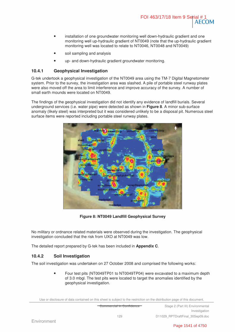
Use or disclosure of data contained on this sheet is subject to the restriction on the distribution page of this document.
Commercial in Confidence Stage 2 (Part III) Environmental
Investigation
129 D11029_RPTDraftFinal_30Sep09.doc
• installation of one groundwater monitoring well down-hydraulic gradient and one monitoring well up-hydraulic gradient of NT0049 (note that the up-hydraulic gradient monitoring well was located to relate to NT0046, NT0048 and NT0049)
• soil sampling and analysis
• up- and down-hydraulic gradient groundwater monitoring.
10.4.1 Geophysical Investigation
G-tek undertook a geophysical investigation of the NT0049 area using the TM-7 Digital Magnetometer system. Prior to the survey, the investigation area was slashed. A pile of portable steel runway plates were also moved off the area to limit interference and improve accuracy of the survey. A number of small earth mounds were located on NT0049.
The findings of the geophysical investigation did not identify any evidence of landfill burials. Several underground services (i.e. water pipe) were detected as shown in Figure 8. A minor sub-surface anomaly (likely steel) was interpreted but it was considered unlikely to be a disposal pit. Numerous steel surface items were reported including portable steel runway plates.
Figure 8: NT0049 Landfill Geophysical Survey
No military or ordnance related materials were observed during the investigation. The geophysical investigation concluded that the risk from UXO at NT0049 was low.
The detailed report prepared by G-tek has been included in Appendix C.
10.4.2 Soil Investigation
The soil investigation was undertaken on 27 October 2008 and comprised the following works:
• Four test pits (NT0049TP01 to NT0049TP04) were excavated to a maximum depth of 3.0 mbgl. The test pits were located to target the anomalies identified by the geophysical investigation.
FOI 463/17/18 Item 9 Serial # 1
Page 1541 of 4750
Use or disclosure of data contained on this sheet is subject to the restriction on the distribution page of this document.
Commercial in Confidence Stage 2 (Part III) Environmental
Investigation
130 D11029_RPTDraftFinal_30Sep09.doc
• One soil bore was drilled to a depth of 11.68 mbgl for the installation of a monitoring well NT0049MW01 down-hydraulic gradient of the area of interest.
• One soil bore was drilled to a depth of 12.62 mbgl for the installation of a monitoring NT0049MW02 well up-hydraulic gradient of the area of interest. The location of this well was selected to provide an up-hydraulic gradient reference for NT0049, NT0046 and NT0065 in addition to NT0048.
The soil sampling and groundwater monitoring locations are presented on Figure F15. Logs describing the subsurface soil profile and groundwater monitoring well construction are provided in Appendix H and Appendix J.
Fill Material
No fill materials were encountered at NT0049.
Natural Soil and Rock
The stratigraphy encountered comprised of brown to red-brown silty to sandy clay units at the surface, overlying clayey sands at 0.5 mbgl (NT0049TP02, NT0049TP03, NT0049TP04), with increasing limestone gravel at depth (NT0049MW01). Massive, slightly weathered limestone rock was encountered at 7.5 mbgl (NT0049MW01).
Rock, comprising massive limestone and limestone boulders, was encountered at 4.5 mbgl at the up-hydraulic gradient background well (NT0049MW02).
PID screening of soil samples did not suggest the presence of volatiles with PID readings ranging from 0 ppm to 0.2 ppm.
10.4.3 Groundwater Investigation
The groundwater investigation was undertaken on 6 November 2008. Two groundwater samples were collected from the newly installed monitoring wells NT0049MW01 and NT0049MW02.
Groundwater inflow was encountered at approximately 10.5 mbgl in NT0049MW01, within the limestone rock. The standing water level measured a week after installation and development was 6.5 mbgl.
Groundwater inflow was encountered at approximately 11.3 mbgl in background well NT0049MW02, at the base of a layer of limestone boulders. The standing water level measured a week after installation and development was 5.54 mbgl.
10.5 Laboratory Analytical Results
10.5.1 Soil Analysis
The soil samples from NT0049 were analysed for a range of CoPC including metals (NEPM 13), TPH, ammonia, nitrates, nitrites and asbestos.
The results of the soil sample laboratory analysis compared against the assessment criteria are summarised in Table T5. Laboratory analytical reports are provided in Appendix I. Figure F15 illustrates all soil test pit locations.
FOI 463/17/18 Item 9 Serial # 1
Page 1542 of 4750
Use or disclosure of data contained on this sheet is subject to the restriction on the distribution page of this document.
Commercial in Confidence Stage 2 (Part III) Environmental
Investigation
131 D11029_RPTDraftFinal_30Sep09.doc
Metals
Twelve soil samples were analysed for metals. All sample concentrations were reported below NEPM HILF. Exceedances of the laboratory LOR and/or NEPM EILs were recorded for the following analytes:
• Vanadium concentrations above the LOR in all samples. Nine of the 12 samples exceeded the NEPM EIL of 50 mg/kg with reported concentrations ranging from 68 mg/kg to 98 mg/kg. All the results were within the background concentration range established for the Base.
• Manganese concentrations above the LOR were reported in all samples. Two of the 12 samples exceeded the NEPM EIL of 500 mg/kg with concentrations ranging from 2,600 mg/kg (NT0049TP02 (1.9 to 2.0 m)) to 2,660 mg/kg (NT0049TP02 (2.9 to 3.0 m)). The results exceeding the NEPM EIL were marginally above the background concentration range established for the Base.
• Barium concentrations above the LOR were recorded in the majority of samples. Two of the 12 samples exceeded the NEPM EIL of 300 mg/kg with concentrations ranging from 430 mg/kg (NT0049TP02 (1.9 to 2.0 m)) to 690 mg/kg(NT0049TP02 (2.9 to 3.0 m)).
• The remaining metal and metalloid analytes (i.e. arsenic, beryllium, cadmium, chromium, cobalt, copper, lead, nickel and zinc) returned concentrations either below the laboratory LOR or below the NEPM EIL.
TPH
Twelve soil samples were analysed for TPH. All concentrations were reported below the laboratory LOR.
Ammonia, Nitrates and Nitrites
Twelve soil samples were analysed for ammonia. All concentrations were reported below the laboratory LOR.
Twelve soil samples were analysed for nitrates. Eight of the 12 samples reported concentrations of nitrates above the LOR with concentrations ranging from 0.101 mg/kg to 0.519 mg/kg.
Twelve soil samples were analysed for nitrites. Two of the 12 samples reported concentrations of nitrites above the LOR with concentrations ranging from 0.175 mg/kg to 0.390 mg/kg.
Asbestos
Two soil samples were submitted for asbestos analysis. Asbestos fibres were not detected in any of the samples.
10.5.2 Groundwater Analysis
Groundwater samples were collected from one down-hydraulic gradient monitoring well NT0049MW01 (located on south west boundary of NT0048) and one up-hydraulic gradient monitoring well NT0049MW02 (located north east of NT0049, NT0048 and NT0065). Groundwater samples were analysed for CoPC including physical parameters, metals (NEPM 13), TPH, PAH, MAH, VOC, SVOC, ammonia, nitrates, nitrites, cations and anions.
The results of the groundwater sample laboratory analysis compared against the assessment criteria are included in Table T6. Laboratory analytical reports are provided in Appendix K. Figure F15 illustrates the groundwater sample locations for NT0049.
FOI 463/17/18 Item 9 Serial # 1
Page 1543 of 4750
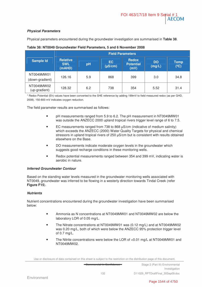
Use or disclosure of data contained on this sheet is subject to the restriction on the distribution page of this document.
Commercial in Confidence Stage 2 (Part III) Environmental
Investigation
132 D11029_RPTDraftFinal_30Sep09.doc
Physical Parameters
Physical parameters encountered during the groundwater investigation are summarised in Table 38.
Table 38: NT0049 Groundwater Field Parameters, 5 and 6 November 2008
Field Parameters
Sample Id Relative SWL
(mAHD) pH
EC (μS/cm)
Redox Potential
(mV)
DO (mg/L)
Temp (ºC)
NT0049MW01
(down-gradient) 126.16 5.9 868 399 3.0 34.8
NT0049MW02 (up-gradient)
128.32 6.2 738 354 5.52 31.4
* Redox Potential (Eh) values have been converted to the SHE reference by adding 199mV to field measured redox (as per GHD,
2008). 150-800 mV indicates oxygen reduction.
The field parameter results are summarised as follows:
• pH measurements ranged from 5.9 to 6.2. The pH measurement in NT0049MW01 was outside the ANZECC 2000 upland tropical rivers trigger level range of 6 to 7.5.
• EC measurements ranged from 738 to 868 μS/cm (indicative of medium salinity) which exceeds the ANZECC (2000) Water Quality Targets for physical and chemical stressors in upland tropical rivers of 250 S/cm but is consistent with results obtained elsewhere on the Base.
• DO measurements indicate moderate oxygen levels in the groundwater which suggests good recharge conditions in these monitoring wells.
• Redox potential measurements ranged between 354 and 399 mV, indicating water is aerobic in nature.
Inferred Groundwater Contour
Based on the standing water levels measured in the groundwater monitoring wells associated with NT0049, groundwater was inferred to be flowing in a westerly direction towards Tindal Creek (refer Figure F15).
Nutrients
Nutrient concentrations encountered during the groundwater investigation have been summarised below:
• Ammonia as N concentrations at NT0049MW01 and NT0049MW02 are below the laboratory LOR of 0.05 mg/L.
• The Nitrate concentrations at NT0049MW01 was (0.12 mg/L) and at NT0049MW02 was 0.20 mg/L, both of which were below the ANZECC 95% protection trigger level of 0.7 mg/L.
• The Nitrite concentrations were below the LOR of <0.01 mg/L at NT0049MW01 and NT0049MW02.
FOI 463/17/18 Item 9 Serial # 1
Page 1544 of 4750

Use or disclosure of data contained on this sheet is subject to the restriction on the distribution page of this document.
Stage 2 (Part III) Environmental
Investigation
133 D11029_RPTDraftFinal_30Sep09.doc
• Total oxidised nitrogen (NOx) concentrations were 0.12 mg/L at NT0049MW01 and 0.20 mg/L at NT0049MW02, both of which are above the ANZECC (2000) Water Quality Targets for physical and chemical stressors of 0.01 mg/L.
Major Ions
Concentrations of major ions encountered during the groundwater investigation have been summarised below. All results were within the ANZECC 2000 stock watering and irrigation water quality guidelines.
• Total anions (total) recorded during the groundwater investigation were 7.73 meq/L at NT0049MW01 and 8.94 meq/L at NT0049MW02:
- Total alkalinity as CaCO3 concentrations recorded were 380 mg/L at NT0049MW01 and 430 mg/L at NT0049MW02
- Chloride concentrations recorded were 4 mg/L at NT0048MW01 and 3 mg/L at NT0049MW02
- Sulphate as SO42- concentrations recorded were 2 mg/L at NT0049MW01 and
13 mg/L in NT0049MW02, which are below the NHMRC drinking water guidelines of 500 mg/L and the interim urban EIL criteria of 2,000 mg/kg.
• Total cations recorded were 7.92 meq/L at NT0049MW01 and 8.48 meq/L at NT0049MW02:
- Calcium concentrations recorded were 94 mg/L at NT0049MW01 and 96 mg/L at NT0049MW02
- Magnesium concentrations recorded were 35 mg/L at NT0049MW01 and 41 mg/l at NT0049MW02
- Sodium concentrations recorded were 6 mg/L at NT0049MW01 and NT0049MW02
- Potassium concentrations were within the laboratory LOR of 1 mg/L NT0049MW01 and NT0049MW02.
Metals
The groundwater samples collected from the two wells reported dissolved concentrations of metals less than the ANZECC 95% protection level trigger values for freshwater ecosystems and the NHMRC (2004) Australian Drinking Water – Health guidelines, with the exception of:
• Copper – concentrations reported at NT0049MW01 (0.003 mg/L) and NT0049MW02 (0.003 mg/L), exceeded the ANZECC 95% protection trigger level of 0.0014 mg/L but were below the NHMRC (2004) Australian Drinking Water – Health of 2 mg/L. All results were within the background concentration ranges established for the Base.
• Lead – concentrations reported at NT0049MW02 (0.006 mg/L) exceeded the ANZECC 95% protection trigger level of 0.0034 mg/L but was below the NHMRC (2004) Australian Drinking water – Health guideline of 0.01 mg/L and within the background concentration range established for the Base.
• Nickel – concentration reported at NT0049MW01 (0.014 mg/L) exceeded the ANZECC 95% protection trigger level of 0.011 mg/L, but was below the NHMRC health drinking water guideline of 0.02 mg/L.
• Zinc – concentrations reported at NT0049MW01 (0.009 mg/L) and NT0049MW02 (0.012 mg/L) exceeded the ANZECC 95% protection trigger level of 0.008 mg/L, but
FOI 463/17/18 Item 9 Serial # 1
Page 1545 of 4750

Use or disclosure of data contained on this sheet is subject to the restriction on the distribution page of this document.
Stage 2 (Part III) Environmental
Investigation
134 D11029_RPTDraftFinal_30Sep09.doc
were below the NHMRC health drinking water guideline of 3 mg/L. All results were within the background concentration range established for the Base.
TPH
The groundwater samples collected from the three wells were analysed for TPH. All concentrations were reported below the laboratory LOR and the site adopted criteria.
VOCs
The groundwater samples collected from the three wells were analysed for VOCs. All concentrations were reported below the laboratory LOR and the site adopted criteria.
The groundwater samples collected from the three wells were analysed for MAH. All concentrations were reported below the laboratory LOR and the site adopted criteria.
SVOCs
The groundwater samples collected from the three wells were analysed for SVOCs. All concentrations were reported below the laboratory LOR and the site adopted criteria.
The groundwater samples collected from the three wells were analysed for PAH. All concentrations were reported below the laboratory LOR and the site adopted criteria.
10.6 Discussion of Site Contamination Issues
10.6.1 Contained Waste
Based on the geophysical and intrusive (test pitting) investigations at NT00049, no evidence of historical land filling was identified.
There was evidence that the area and surrounds had been previously used as living quarters, based on the observed concrete footings and potential ACM fragments. Underground services were identified running along the eastern edge of the site. It is suspected that this is the heli-pad irrigation line (which may or may not still be in use).
The surface of NT0049 was scattered with miscellaneous waste materials including 205 L drum, a pile of portable steel runway, razor wire and star pickets. A number of small earthen mounds were also identified in the area. It was noted that potential ACM (i.e. fibrous cement sheeting fragments and pipes) were observed during the Stage 2 (III) Investigation. As such, the presence of asbestos and ACM cannot be discounted as posing a risk at this site.
No military or ordnance related materials were observed during the investigation.
10.6.2 Soil Contamination
Soil analysis results from NT0049 were all within the NEPM HILF for industrial/commercial land use. A number of sample analysis results reported elevated metals concentrations, including vanadium, manganese and barium, which exceeded the NEPM EIL guidelines. These results were generally recorded for samples collected at depth (i.e. greater then 1.9 mbgl) and were generally consistent with background concentrations established for the Base.
There was no evidence of explosive residues (i.e. ammonia, nitrates and nitrites) reported by the soil samples collected as part of the investigations.
FOI 463/17/18 Item 9 Serial # 1
Page 1546 of 4750

Use or disclosure of data contained on this sheet is subject to the restriction on the distribution page of this document.
Commercial in Confidence Stage 2 (Part III) Environmental
Investigation
135 D11029_RPTDraftFinal_30Sep09.doc
Asbestos contamination was not reported by the soil samples collected as part of the investigations. However, potential ACM (specifically fibrous cement sheeting fragments and pipes) were observed on the area surface.
10.6.3 Groundwater Contamination
In general, the analysis results from the groundwater samples collected from the one well down-hydraulic gradient of NT0049 were less than the adopted site assessment criteria. The only exceptions to this were as follows.
• Concentrations of copper, nickel and zinc exceeded the ANZECC 95% protection trigger values but were generally consistent with background levels established for the Base.
• Electrical conductivity measurements exceeded the ANZECC (2000) Water Quality Targets for physical and chemical stressors in upland tropical rivers but were generally consistent with levels reported for other areas across the Base.
• Concentrations of oxidised nitrogen (NOx) exceeded the ANZECC (2000) Water Quality Targets for physical and chemical stressors but were consistent with results recorded at other locations across the Base indicating that nutrients are naturally occurring.
The groundwater quality and ionic balance reported in the groundwater monitoring well (NT0049MW1) located down-hydraulic gradient of NT0049 was similar to those reported for the up-gradient well (NT0049MW2). This suggests that there has been little, if any, impact to the groundwater as a result of historical activities in this area.
10.7 Summary and Recommendations
10.7.1 Nature and Extent of Contamination
The findings of the Stage 2 (III) Investigations at NT0049 are as follows:
• Chemical contamination: Chemical contamination was not identified in soil or groundwater that exceeded the NEPM HILF for industrial/commercial land use and the ANZECC 95% protection trigger values, respectively. No explosive residues above detection limits, evidence of UXO, or buried waste were detected during the intrusive investigation. However, potential ACM was identified on the surface across the area of interest and the surrounding area.
• Chemicals of Concern:
- Nil
• Buried Waste:
- No evidence of landfill
• Soil Investigations:
- Contaminant concentrations identified in the soil are not expected to pose an adverse human health risk and are considered to be acceptable for continuing commercial/industrial land use.
- Elevated metal concentrations (specifically vanadium, manganese and barium) were reported at a number of locations which exceeded the NEPM EIL (but were less than the NEPM HILF and generally consistent with the background concentrations determined for the Base).
FOI 463/17/18 Item 9 Serial # 1
Page 1547 of 4750

Use or disclosure of data contained on this sheet is subject to the restriction on the distribution page of this document.
C Stage 2 (Part III) Environmental
Investigation
136 D11029_RPTDraftFinal_30Sep09.doc
- All other soil concentrations were reported below the NEPM HILF and EILs.
- Potential ACM was observed on the ground surface of the area of interest and in the surrounding areas.
• Groundwater Investigation:
- Contaminant concentrations identified in groundwater are not expected to pose an adverse impact to human health and are considered to be acceptable for continuing commercial/industrial land use.
- Copper, lead, zinc and nickel were reported at concentrations which exceeded the ANZECC 95% protection trigger level, but were below the NHMRC (2004) Australian Drinking water-Health guideline and were consistent with background levels.
- EC measurements exceeded the ANZECC (2000) Water Quality Targets for physical and chemical stressors in upland tropical rivers but were generally consistent with levels reported in previous groundwater monitoring events around the Base.
- Nitrogen (NOx) exceeded the ANZECC (2000) Water Quality Targets for physical and chemical stressors of 0.01 mg/L but was consistent with the results reported at other locations across the Base.
- All other groundwater concentrations were reported below the ANZECC trigger levels.
10.7.2 Risks Identified
Appendix L summarises the assessment of risks associated with the identified contamination at NT0049. The results of the Stage 2 (III) risk assessment are summarised following:
• NT0049 – High Risk Band with a Risk Priority score of 186 based on on presence of potential ACM at the surface where human contact is possible (OHS dimension).
10.7.3 Site Specific Recommendations
NT0049 is located within main OA of RAAF Tindal near the SAR hangar. Public access to these areas is restricted. However, Defence training activities, and/or site redevelopment, may result in Defence personnel and contractors accessing this area. As such, the following recommendations have been made in relation to NT0049.
• remove suspected ACM from the surface by ‘Emu Pick’ (manual collection), completed by an appropriately licensed contractor from across the area of interest surface
• dispose of ACM to an offsite licensed facility
• include area as part of the CEMP (being prepared separately as part of the Stage 2 (III) Investigations
• include the area on the Base Asbestos Register
• consider the removal of waste (i.e. drums, portable runways, etc.) scattered over the surface of NT0049 to reduce the risk of negative impact to the visual amenity of the area and risk to human health and safety (e.g. star pickets, razor wire, etc. at the surface).
FOI 463/17/18 Item 9 Serial # 1
Page 1548 of 4750
Use or disclosure of data contained on this sheet is subject to the restriction on the distribution page of this document.
Commercial in Confidence Stage 2 (Part III) Environmental
Investigation
137 D11029_RPTDraftFinal_30Sep09.doc
11.0 Site Investigation – NT0050 Waste Disposal Area near Ordnance Preparation Area
11.1 Area Description
NT0050 (Waste Disposal Area near Ordnance Preparation Area) is located on the southern side of Cape Gloucester Road, approximately 110 m west of the 75 SQN Ordnance Preparation Area (OPA) boundary fence (Figure F16).
The area was observed to incorporate large piles of discarded cement, concrete, boulders and steel debris which was clearly visible at the ground surface and was not buried or covered. The area of interest is irregular in shape, approximately 700 m long x 400 m wide.
The location of the area of interest has been described in Table 39.
Table 39: NT0050 Investigation Site Description
Coordinates* Landfill No. Description of Area
NW Corner SE Corner
Size (ha)
NT0050 Located southern side of Cape Gloucester Road, approximately 110 m from ordnance preparation area fence
-14.535071ºS
132.394729ºE
-14.535245ºS
132.400563ºE
~23.71
* Latidude/Longitude DATUM WGS 84
Photographs were taken of the areas of interest and are presented in the Plates Section of this report (Plate 65 to Plate 80).
The Waste Disposal near Ordnance Preparation Area (NT0050) was bounded by:
• native bushland and Tindal Creek to the south
• security fence of the Operational Area of RAAF Tindal to the west
• 75 Squadron Compound and Ordnance Loading Aprons to the north
• Ordnance Preparation Area (OPA) compound and native bushland to the east.
11.2 Objectives of the Stage 2 Investigation
To meet the overall objective of the Stage 2 (III) Investigation of defining the ‘true risks’ to Defence of potential contamination, NT0050 (Waste Disposal near Ordnance Preparation Area) were investigated to:
• delineate the vertical and lateral extent of landfill material and chemical contamination (to the extent practical)
• quantify and characterise waste material within landfill
• measure concentrations of contaminants within groundwater and soils
• identify potential human health and ecological receptors
FOI 463/17/18 Item 9 Serial # 1
Page 1549 of 4750
Use or disclosure of data contained on this sheet is subject to the restriction on the distribution page of this document.
Commercial in Confidence Stage 2 (Part III) Environmental
Investigation
138 D11029_RPTDraftFinal_30Sep09.doc
• assess the potential for waste materials and/or impacted soils to leach contaminants of concern into groundwater and nearby receiving waters.
11.3 Historical Information, Previous Investigations and Potential Chemicals of Concern
11.3.1 Previous Reports
The Landfill/Burial Sites Stage 1 Environmental Investigation (Stage 1 EI) prepared by ERM (2007b) included an assessment of the status of NT0050 (Waste Disposal Area near Ordnance Preparation Area).
The Stage 1 EI (ERM, 2007b) reported that the disposal area was irregular in shape and was used for the disposal of building rubble and concrete. Additionally, there is a potential for UXO as the area was reportedly used for disposal of ordnance preparation waste. ERM estimated the disposal area was approximately 60 m x 30 m. A fissure was also noted to run through the centre of the disposal area. Prior to its use as a disposal area, it is believed the area was occupied by ordnance bunkers. Visual observations suggested that the area was no longer used for waste disposal.
The Stage 1 EI concluded that NT0050 posed a medium risk based on human exposure to contaminated groundwater or surface water.
The recommendations in the Stage 1 EI were:
• fencing of the area
• conduct a geophysical investigation
• groundwater monitoring.
11.3.2 Historical Aerial Photographs
A limited review of the available historical aerial photographs at the office of Defence Support – Tindal (DS-Tindal) was undertaken during the Stage 2 (III) Investigations for the NT0050 landfill area to assist in identifying the areas of interest.
The photographs showed a history of disturbance across the area, including a number of scraps located throughout the area.
11.3.3 Potential Chemicals of Concern
Based on the available historical information, the potential chemicals of concern at NT0050 include:
• heavy metals (i.e. arsenic, barium, beryllium, cadmium, chromium, copper, manganese, nickel, lead, mercury, vanadium and zinc) from scrap steel waste
• nitrated compounds and ammonia from explosives residues
• asbestos from disused building materials and rubble
• hydrocarbons (TPH, PAH, MAH and chlorinated) because the unknown nature of the landfilled waste.
11.4 Stage 2 (III) Intrusive Investigation
The Stage 2 (III) intrusive investigation at NT0050 consisted of:
• a geophysical investigation
FOI 463/17/18 Item 9 Serial # 1
Page 1550 of 4750
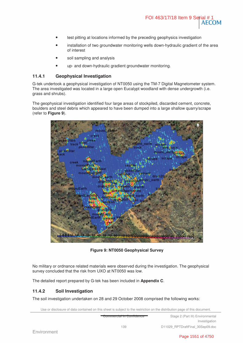
Use or disclosure of data contained on this sheet is subject to the restriction on the distribution page of this document.
Commercial in Confidence Stage 2 (Part III) Environmental
Investigation
139 D11029_RPTDraftFinal_30Sep09.doc
• test pitting at locations informed by the preceding geophysics investigation
• installation of two groundwater monitoring wells down-hydraulic gradient of the area of interest
• soil sampling and analysis
• up- and down-hydraulic gradient groundwater monitoring.
11.4.1 Geophysical Investigation
G-tek undertook a geophysical investigation of NT0050 using the TM-7 Digital Magnetometer system. The area investigated was located in a large open Eucalypt woodland with dense undergrowth (i.e. grass and shrubs).
The geophysical investigation identified four large areas of stockpiled, discarded cement, concrete, boulders and steel debris which appeared to have been dumped into a large shallow quarry/scrape (refer to Figure 9).
Figure 9: NT0050 Geophysical Survey
No military or ordnance related materials were observed during the investigation. The geophysical survey concluded that the risk from UXO at NT0050 was low.
The detailed report prepared by G-tek has been included in Appendix C.
11.4.2 Soil Investigation
The soil investigation undertaken on 28 and 29 October 2008 comprised the following works:
FOI 463/17/18 Item 9 Serial # 1
Page 1551 of 4750
Use or disclosure of data contained on this sheet is subject to the restriction on the distribution page of this document.
Commercial in Confidence Stage 2 (Part III) Environmental
Investigation
140 D11029_RPTDraftFinal_30Sep09.doc
• Thirteen test pits (NT0050TP01 to NT0050TP13) were excavated to a maximum depth of 3.0 mbgl. The test pits were located to target the areas within and surrounding the debris stockpiles identified by the geophysical investigation.
• Two soil bores were drilled to a depth of 11.8 mbgl and 6.5 mbgl for the installation of monitoring wells, NT0050MW01 and NT0050MW02 respectively, located down-hydraulic gradient of the area of interest.
The soil sampling and groundwater monitoring locations and elevated results are presented on Figure F17. Logs describing the subsurface soil profile and groundwater monitoring well construction are provided in Appendix H and Appendix J.
Fill Material
Fill was not encountered consistently across NT0050. Slight odours and elevated PID readings were noted at: surface samples at NT0050TP04 (14.1 ppm) and NT0050TP02 (4 ppm); and, 2 mbgl at NT0050TP04 (2.4 ppm). These observations may be indicative of localised or spot contamination, or that the surface units in the vicinity of NT0050TP04 have been reworked.
PID screening of all other soil samples did not suggest the presence of volatiles with PID readings less than 1 ppm.
Large areas of stockpiled, discarded cement, concrete, boulders and steel debris were observed in the south-western corner of the investigation area, as discussed in Section 11.4.1.
Natural Soil and Rock
The stratigraphy encountered comprised variable units of orange brown silty clay, clayey silt and sand at surface. More cohesive yellow brown and red brown clay was encountered at 2 mbgl to 3 mbgl within test pit NT0050TP06, NT0050TP07, NT0050TP09, NT0050TP10 and NT0050TP12. Limestone boulders, resulting in test pit refusal, were encountered at 2.1 to 2.6 mbgl within test pits NT0050TP09, NT0050TP10, NT0050TP11 and NT0050TP13.
The stratigraphy encountered during the drilling investigation on the southern portion of the site comprised of silt, sandy silt and clayey sand at surface to approximately 1 mbgl, overlying cohesive yellow brown silty clay from approximately 2 mbgl to 5 mbgl, overlying gravelly clay and clayey limestone gravel at greater depths. Rock was encountered during the drilling of well NT0050MW02 and comprised moderately weathered, porous limestone at 6.2 mbgl.
11.4.3 Groundwater Investigation
The groundwater investigation was undertaken on 11 November 2008. Two groundwater samples were collected from the newly installed monitoring wells NT0050MW01 and NT0050MW02.
Groundwater inflow was encountered at variable depths of 10.9 mbgl at NT0050MW01 within gravelly clay, and at 5.75 mbgl at NT0050MW02 within clayey limestone gravel. The standing water levels measured a week after installation and development were 5.7 mbgl at NT0050MW01 and 3.25 mbgl at NT0050MW02.
11.5 Laboratory Analytical Results
11.5.1 Soil Analysis
The soil samples from NT0050 were analysed for a range of CoPC including metals (NEPM 13), TPH, PAHs, MAH, VOC, SVOC, ammonia, nitrates, nitrites and asbestos.
FOI 463/17/18 Item 9 Serial # 1
Page 1552 of 4750

Use or disclosure of data contained on this sheet is subject to the restriction on the distribution page of this document.
Commercial in Confidence Stage 2 (Part III) Environmental
Investigation
141 D11029_RPTDraftFinal_30Sep09.doc
The results of the soil sample laboratory analysis of surface soils compared against the assessment criteria are included in Table T7. Laboratory analytical reports are provided in Appendix I.
Metals
Thirty-nine soil samples were analysed for metals. All sample concentrations were reported below NEPM HILF. Exceedances of the laboratory LOR and/or NEPM EILs where recorded for the following analytes:
• Vanadium concentrations above the LOR were reported in all samples. Twenty-four of the 39 samples exceeded the NEPM EIL of 50 mg/kg, with the highest concentration (146 mg/kg) measured at NT0050TP06 (2.9 to 3.0 m). With the exception NT0050TP06, all results were within the background concentration range established for the Base.
• Manganese concentrations above the LOR were recorded in all samples. Five of the 39 samples exceeded the NEPM EIL of 500 mg/kg ranging from 550 mg/kg to 2,120 mg/kg, but were within the background concentration range established for the Base.
• Barium concentrations above the LOR were recorded at 23 of the 39 soil samples. One of the 39 samples, NT0050TP12 (2.9 to 3.0 m), exceeded the NEPM EIL of the 300 mg/kg returning a concentration of 680 mg/kg. All concentrations were within the NEPM background concentration range for the Base.
• Nickel concentrations above the LOR were recorded at all sample locations. One of the 39 samples, NT0050TP12 (2.9 to 3.0 m), reported a concentration (61 mg/kg) that just exceeded the NEPM EIL of the 60 mg/kg.
• The remaining metal and metalloid analytes (i.e. arsenic, beryllium, cadmium, chromium, cobalt, copper, lead and nickel) returned concentrations with below the laboratory LOR or below the NEPM EIL.
TPH
Thirty-nine soil samples were analysed for TPH. All concentrations were reported below the laboratory LOR and the site adopted criteria.
VOCs
Four soil samples (equating to approximately 10%) were analysed for VOCs. All concentrations were reported below the laboratory LOR the site adopted criteria.
Thirty-nine soil samples were analysed for MAH. All concentrations were reported below the laboratory LOR the site adopted criteria.
SVOCs
Four soil samples (equating to approximately 10%) were analysed for SVOC. All concentrations were reported below the laboratory LOR the site adopted criteria.
Thirty-nine soil samples were analysed for PAH. All concentrations were reported below the laboratory LOR the site adopted criteria.
FOI 463/17/18 Item 9 Serial # 1
Page 1553 of 4750
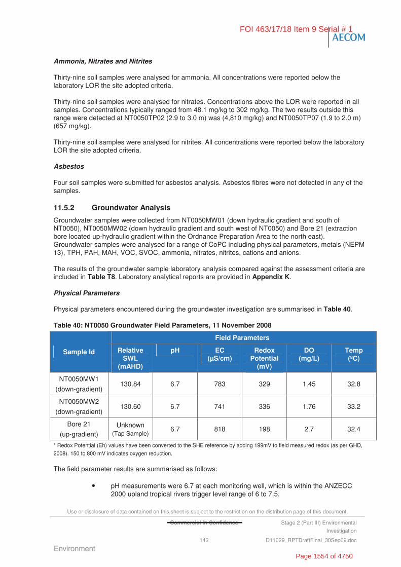
Use or disclosure of data contained on this sheet is subject to the restriction on the distribution page of this document.
Commercial in Confidence Stage 2 (Part III) Environmental
Investigation
142 D11029_RPTDraftFinal_30Sep09.doc
Ammonia, Nitrates and Nitrites
Thirty-nine soil samples were analysed for ammonia. All concentrations were reported below the laboratory LOR the site adopted criteria.
Thirty-nine soil samples were analysed for nitrates. Concentrations above the LOR were reported in all samples. Concentrations typically ranged from 48.1 mg/kg to 302 mg/kg. The two results outside this range were detected at NT0050TP02 (2.9 to 3.0 m) was (4,810 mg/kg) and NT0050TP07 (1.9 to 2.0 m) (657 mg/kg).
Thirty-nine soil samples were analysed for nitrites. All concentrations were reported below the laboratory LOR the site adopted criteria.
Asbestos
Four soil samples were submitted for asbestos analysis. Asbestos fibres were not detected in any of the samples.
11.5.2 Groundwater Analysis
Groundwater samples were collected from NT0050MW01 (down hydraulic gradient and south of NT0050), NT0050MW02 (down hydraulic gradient and south west of NT0050) and Bore 21 (extraction bore located up-hydraulic gradient within the Ordnance Preparation Area to the north east). Groundwater samples were analysed for a range of CoPC including physical parameters, metals (NEPM 13), TPH, PAH, MAH, VOC, SVOC, ammonia, nitrates, nitrites, cations and anions.
The results of the groundwater sample laboratory analysis compared against the assessment criteria are included in Table T8. Laboratory analytical reports are provided in Appendix K.
Physical Parameters
Physical parameters encountered during the groundwater investigation are summarised in Table 40.
Table 40: NT0050 Groundwater Field Parameters, 11 November 2008
Field Parameters
Sample Id Relative SWL
(mAHD)
pH EC (μS/cm)
Redox Potential
(mV)
DO (mg/L)
Temp (ºC)
NT0050MW1
(down-gradient) 130.84 6.7 783 329 1.45 32.8
NT0050MW2
(down-gradient) 130.60 6.7 741 336 1.76 33.2
Bore 21
(up-gradient) Unknown
(Tap Sample) 6.7 818 198 2.7 32.4
* Redox Potential (Eh) values have been converted to the SHE reference by adding 199mV to field measured redox (as per GHD,
2008). 150 to 800 mV indicates oxygen reduction.
The field parameter results are summarised as follows:
• pH measurements were 6.7 at each monitoring well, which is within the ANZECC 2000 upland tropical rivers trigger level range of 6 to 7.5.
FOI 463/17/18 Item 9 Serial # 1
Page 1554 of 4750
Use or disclosure of data contained on this sheet is subject to the restriction on the distribution page of this document.
Commercial in Confidence Stage 2 (Part III) Environmental
Investigation
143 D11029_RPTDraftFinal_30Sep09.doc
• EC measurements ranged from 741 to 818 μS/cm (indicative of moderate salinity) which exceeds the ANZECC (2000) Water Quality Targets for physical and chemical stressors in upland tropical rivers of 250 S/cm but is consistent with results obtained elsewhere on the Base.
• DO measurements indicate moderate oxygen levels in the groundwater which suggests good recharge conditions in these bores.
• Redox potential measurements ranged between 198 to 336 mV, indicating water is reducing in nature.
Inferred Groundwater Contours
Based on the standing water levels measured in the groundwater monitoring wells associated with NT0050, groundwater was inferred to be flowing in a south west direction towards Tindal Creek (refer Figure F17).
Nutrients
Nutrient concentrations encountered during the groundwater investigation have been summarised following.
• Ammonia as N concentrations ranged from <0.01 mg/L in NT0050MW02 and Bore 21 to 0.04 mg/L in NT0050MW01, all of which are below the ANZECC 95% protection trigger level o f 0.9 mg/L.
• The Nitrate concentrations ranged from 0.12 mg/L at NT0050MW01, 0.07 mg/L at NT0050MW02 to <0.01 mg/L at Bore 21, all of which are below the ANZECC 95% protection trigger level of 0.7 mg/L.
• Nitrite concentrations were below the laboratory LOR at all monitoring wells.
• Total oxidised nitrogen (NOx) concentrations were 0.12 mg/L at NT0050MW01 and 0.07 mg/L at NT0050MW02, both of which are above the ANZECC (2000) Water Quality Targets for physical and chemical stressors of 0.01 mg/L. Bore 21 returned NOx concentrations below the laboratory LOR.
Major Ions
Concentrations of major ions encountered during the groundwater investigation have been summarised following. All results were within the ANZECC 2000 stock watering and irrigation water quality guidelines.
• Total anions (total) recorded during the groundwater investigation were 8.97 meq/L at NT0050MW01, 8.66 meq/L at NT0050MW02 and 9.63 meq/L at Bore 21.
- Total alkalinity as CaCO3 concentrations recorded were 422 mg/L at NT0050MW01, 425 mg/L at NT0050MW02 and 474 mg/L at Bore 21.
- Chloride concentrations were 15 mg/L at NT0050MW01, 3 mg/L at NT0050MW02 and 5 mg/L at Bore 21.
- Sulphate as SO42- concentrations recorded were 6 mg/L at NT0050MW01 and
4 mg/L at NT0050MW02, both of which are below the NHMRC drinking water guidelines of 500 mg/L. Bore 21 returned concentrations below the laboratory LOR.
FOI 463/17/18 Item 9 Serial # 1
Page 1555 of 4750
Use or disclosure of data contained on this sheet is subject to the restriction on the distribution page of this document.
Commercial in Confidence Stage 2 (Part III) Environmental
Investigation
144 D11029_RPTDraftFinal_30Sep09.doc
• Total cations concentrations ranged from 8.34 meq/L at NT0050MW01, 8.11 meq/L at NT0050MW02 and 9.29 meq/L at Bore 21.
- Calcium concentrations ranged from 96 mg/L to 100 mg/L at the three monitoring locations.
- Magnesium concentrations recorded 36 mg/L at NT0050MW01, 34 mg/L at NT0050MW02 and 49 mg/L at Bore 21.
- Sodium concentrations recorded 11 mg/L at NT0050MW01, 6 mg/L at NT0050MW02 and 8 mg/L at Bore 21.
• Potassium concentrations recorded 2 mg/L at the three monitoring locations
Metals
The groundwater samples collected from the three wells reported dissolved concentrations of metals less than the ANZECC 95% protection level trigger values for freshwater ecosystems and the NHMRC (2004) Australian Drinking Water – Health guidelines, with the following exceptions:
• Nickel – concentrations reported at NT0050MW01 (0.053 mg/L) and NT0050MW02 (0.04 mg/L) exceeded the ANZECC 95% protection trigger level of 0.011 mg/L and the NHMRC health drinking water guideline of 0.02 mg/L. The concentration reported for Bore 21 was less than the laboratory LOR.
• Zinc – concentrations reported at NT0050MW02 (0.010 mg/L) and Bore 21 (0.018 mg/L) exceeded the ANZECC 95% protection trigger level of 0.008 mg/L, but were below the NHMRC health drinking water guideline of 3 mg/L. All results were within the background concentration range established for the Base.
TPH
The groundwater samples collected from the three wells were analysed for TPH. All concentrations were reported below the laboratory LOR and the site adopted criteria.
VOCs
The groundwater samples collected from the three wells were analysed for VOCs. All concentrations were reported below the laboratory LOR and the site adopted criteria.
The groundwater samples collected from the three wells were analysed for MAH. All concentrations were reported below the laboratory LOR and the site adopted criteria.
SVOCs
The groundwater samples collected from the three wells were analysed for SVOCs. All concentrations were reported below the laboratory LOR and the site adopted criteria.
The groundwater samples collected from the three wells were analysed for PAH. All concentrations were reported below the laboratory LOR and the site adopted criteria.
11.6 Discussion of Site Contamination Issues
11.6.1 Contained Waste
Based on the geophysical and intrusive (test pitting) investigations at NT0050, four clearly visible areas of stockpiled, discarded cement, concrete, boulders and steel debris were located on site (refer to
FOI 463/17/18 Item 9 Serial # 1
Page 1556 of 4750

Use or disclosure of data contained on this sheet is subject to the restriction on the distribution page of this document.
Commercial in Confidence Stage 2 (Part III) Environmental
Investigation
145 D11029_RPTDraftFinal_30Sep09.doc
Figure 9). The footprints of the four areas (from SW to the NE – refer to Figure 9) are estimated as follows:
• Area 1 – 8,060 m2 with an estimated contained waste volume of 8060m3, based on a maximum depth of fill to 1 mbgl.
• Area 2 – 29,673 m2 with an estimated contained waste volume of 29,673m3, based on a maximum depth of fill to 1 mbgl.
• Area 3 – 5,346m2 with an estimated contained waste volume of 5,346m3, based on a maximum depth of fill to 1 mbgl.
• Area 4 – 1,034 m2 with an estimated contained waste volume of 1,034m3, based on a maximum depth of fill to 1 mbgl.
The majority of materials identified in the stockpiles/landfill consisted of inert waste such as concrete and limestone boulders). Some steel debris and surface scatters of star pickets, asphalt, reo-wire were also observed across the area.
No military or ordnance related materials were observed during the investigation.
11.6.2 Soil Contamination
Soil analysis results from NT0050 were all within the NEPM HILF for industrial/commercial land use. A number of sample analysis results reported elevated metal concentrations, including vanadium, manganese, barium and nickel, which exceed the NEPM EILs. The results are consistent with the expected background concentrations within the area; however, the potential for anthropogenic impact from observed scrap metal waste can not be discounted.
There was no evidence of explosive residues reported by the soil samples collected as part of the investigations. Nitrate concentrations were elevated across the site which may suggest anthropogenic impact from former ordnance handling which is understood to have occurred in the area.
Asbestos contamination was not reported by the soil samples collected as part of the investigations. Additionally, there was no surface evidence of ACM noted during the investigation.
11.6.3 Groundwater Contamination
In general, the analysis results from the groundwater samples collected from the two wells down-hydraulic gradient of NT0050 and the one well up-hydraulic gradient of NT0050 were less than the adopted site assessment criteria. The only exceptions to this were as follows.
• Concentrations of nickel and zinc exceeded the ANZECC 95% protection trigger values. Nickel and zinc concentrations were generally consistent with background levels established for the Base.
• Electrical conductivity measurements exceeded the ANZECC (2000) Water Quality Targets for physical and chemical stressors in upland tropical rivers but were generally consistent with levels reported for other areas across the Base.
• Concentrations of oxidised nitrogen (NOx) exceeded the ANZECC (2000) Water Quality Targets for physical and chemical stressors but were consistent with results recorded at other locations across the Base indicating that nutrients are naturally occurring.
• The groundwater quality and ionic balance reported in the groundwater monitoring wells (NT0050MW01 and NT0050MW02) located down-hydraulic gradient of NT0050 was similar to that reported for the up-gradient well (Bore 21). This suggests that
FOI 463/17/18 Item 9 Serial # 1
Page 1557 of 4750
Use or disclosure of data contained on this sheet is subject to the restriction on the distribution page of this document.
Commercial in Confidence Stage 2 (Part III) Environmental
Investigation
146 D11029_RPTDraftFinal_30Sep09.doc
there has been little, if any, impact to the groundwater as a result of historical activities in this area.
11.7 Summary and Recommendations
11.7.1 Nature and Extent of Contamination
The findings of the Stage 2 (III) Investigations at NT0050 are as follows:
• Chemical contamination: Chemical contamination was not identified in soil or groundwater that exceeded the NEPM HILF for industrial/commercial land use and the ANZECC 95% protection trigger values, respectively. No explosive residues above detection limits, evidence of UXO, asbestos or evidence of ACM were detected during the intrusive investigation.
• Chemicals of Concern:
- Nitrates in soils
- Nickel in groundwater.
• Buried Wastes:
- Evidence of four discrete landfill burials comprising stockpiled, discarded cement, concrete, boulders and steel debris. Additionally widespread miscellaneous waste materials, including star pickets, asphalt and reo-wire were at the surface.
- Based on the intrusive investigations, the four landfill footprints are estimated as follows:
Area 1 – 8,060 m2 with an estimated contained waste volume of 8060m3, based on a maximum depth of fill to 1 mbgl.
Area 2 – 29,673 m2 with an estimated contained waste volume of 29,673m3, based on a maximum depth of fill to 1 mbgl.
Area 3 – 5,346m2 with an estimated contained waste volume of 5,346m3, based on a maximum depth of fill to 1 mbgl.
Area 4 – 1,034 m2 with an estimated contained waste volume of 1,034m3, based on a maximum depth of fill to 1 mbgl.
• Soil Investigations:
- Contaminant concentrations identified in soil are not expected to pose an adverse impact to human health and are considered to be acceptable for continuing commercial/industrial land use.
- Elevated metal concentrations (specifically vanadium, zinc, manganese and barium) were reported which exceeded the NEPM EIL (but less than NEPM HILF and were generally consistent with background concentrations determined for the Base).
- Nitrate concentrations identified in soils were elevated across the site which may suggest anthropogenic impact from former ordnance handling which is understood to have occurred in the area.
- All other soil concentrations were reported below the NEPM HILF and EILs.
- Asbestos contamination was not detected within the soil samples and ACM was not observed during the investigations.
FOI 463/17/18 Item 9 Serial # 1
Page 1558 of 4750
Use or disclosure of data contained on this sheet is subject to the restriction on the distribution page of this document.
Commercial in Confidence Stage 2 (Part III) Environmental
Investigation
147 D11029_RPTDraftFinal_30Sep09.doc
• Groundwater Investigation:
- Contaminant concentrations identified in groundwater are not expected to pose an adverse impact to human health and are considered to be acceptable for continuing commercial/industrial land use.
- Nickel and zinc were reported at concentrations which exceeded the ANZECC 95% protection trigger level, but were below the NHMRC (2004) Australian Drinking water-Health guideline. Zinc concentrations were consistent with background levels.
- Total oxidised nitrogen (NOx) exceeded the ANZECC (2000) Water Quality Targets for physical and chemical stressors of 0.01 mg/L but were consistent with the results reported at other locations across the Base.
- EC measurements exceeded the ANZECC (2000) Water Quality Targets for physical and chemical stressors in upland tropical rivers of 250 S/cm but were generally consistent with levels reported in previous groundwater monitoring events around the Base.
- All other groundwater concentrations of CoPC (i.e. TPH, PAH, MAH, VOC and SVOC) were below the adopted assessment criteria.
11.7.2 Risks Identified
Appendix L summarises the assessment of risks associated with the identified contamination at NT0050. The results of the Stage 2 (III) risk assessment are summarised as follows:
• NT0050 – Low Risk Band with a Risk Priority score of 198 based on the remote location to occupied areas and that the investigation did not identify any explosive residues above detection limits, evidence of UXO, asbestos or evidence of ACM.
11.7.3 Site Specific Recommendations
NT0050 is located south west of the Ordnance Preparation Area (OPA), outside the main Base security fence. Public access to these areas is possible but unlikely. However, Defence training activities, and/or site redevelopment, may result in Defence personnel and contractors accessing this site. As such, the following recommendations have been made in relation to NT0050.
• Include NT0050 on the site specific CEMP (being prepared separately as part of the Stage 2 (III) Investigations, highlighting location of the inert landfill materials.
• Consider the removal of waste (i.e. drums, portable runways etc.) scattered over the surface of NT0049 to reduce the risk of negative impact to the visual amenity of the area and risk to human health and safety (e.g. star pickets, razor wire, etc. at the surface).
FOI 463/17/18 Item 9 Serial # 1
Page 1559 of 4750

Use or disclosure of data contained on this sheet is subject to the restriction on the distribution page of this document.
Commercial in Confidence Stage 2 (Part III) Environmental
Investigation
148 D11029_RPTDraftFinal_30Sep09.doc
“This page has been left blank intentionally”
FOI 463/17/18 Item 9 Serial # 1
Page 1560 of 4750
Use or disclosure of data contained on this sheet is subject to the restriction on the distribution page of this document.
Commercial in Confidence Stage 2 (Part III) Environmental
Investigation
149 D11029_RPTDraftFinal_30Sep09.doc
12.0 Site Investigation – NT0051 Hornet Aircraft and Tactical Unmanned Aerial Vehicle Burial Site
12.1 Area Description
NT0051 (Hornet Aircraft and Tactical UAV Burial Site) was re-located during the Stage 2 (III) Investigation in bushland on the north eastern portion of the Base near historic scrapes used for construction of RAAF Tindal. The area is located approximately 1.9 km west of the Stuart Highway and 1.2 km along dirt tracks from the Base Security fence (Figure F18). The site was found to be surrounded with a deteriorated star picket fence and signposted as ‘Contaminated Land’ (Plate 81 and Plate 82).
NT0051 was reportedly used for the burial of an FA/18 Hornet aircraft, which crashed on 2 August 1990, and the burial of a tactical UAV (date not known). It was reported that prior to the burial of the FA/18, the carbon fibre wreckage was covered in floor-polish to minimize the risk of inhalation of the toxic fibres.
The location of the area of interest is described in Table 41.
Table 41: NT0051 Investigation Location
Coordinates* Landfill No. Description of Area
NW Corner SE Corner
Size (ha)
NT0051 Located in bushland on the north eastern portion of the Base near the scraps. The site is approximately 1.2 km along dirt tracks from the Base Security fence.
-14.517009ºS
132.410885ºE
-14.517515ºS
132.410677ºE
~0.15
* Latidude/Longitude DATUM WGS 84
Photographs were taken of the areas of interest and have been provided in the Plates Section of this report (Plate 81 to Plate 86).
The Hornet Aircraft and tactical UAV burial site (NT0051) was bounded by:
• historical scrapes and native bushland to the south
• more scrapes and RAAF Tindal administration area to the west
• native bushland to the north
• native bushland and the Stuart Highway to the east.
12.2 Objectives of the Stage 2 Investigation
To meet the overall objective of the Stage 2 (III) Investigation of defining the ‘true risks’ to Defence of potential contamination, NT0051 (Hornet Aircraft and Tactical UAV burial site) were investigated to:
• confirm location of the reported burial site
FOI 463/17/18 Item 9 Serial # 1
Page 1561 of 4750
Use or disclosure of data contained on this sheet is subject to the restriction on the distribution page of this document.
Commercial in Confidence Stage 2 (Part III) Environmental
Investigation
150 D11029_RPTDraftFinal_30Sep09.doc
• quantify whether the burial has had an impact on the surrounding soils and characterise the impact
• measure concentrations of contaminants within soil and groundwater
• identify potential human health and ecological receptors
• assess the potential for waste materials and/or impacted soils to leach contaminants of concern into groundwater and nearby receiving waters.
12.3 Historical Information, Previous Investigations and Potential Chemicals of Concern
12.3.1 Previous Reports
The Landfill/Burial Sites Stage 1 Environmental Investigation (Stage 1 EI) prepared by ERM (2007b) included an assessment of the status of NT0051 (FA/18 Hornet aircraft and tactical UAV burial site).
The Stage 1 EI (ERM, 2007b) reported that the FA/18 and UAV was buried in the early 1990s. Prior to its use as a disposal area, it is believed the area of interest was bushland/agricultural land.
The Stage 1 EI concluded that NT0051 posed a medium risk based on human exposure to contaminated groundwater or surface water and exposure to buried contents.
The recommendations in the Stage 1 EI were:
• fencing of the area
• conduct a geophysical survey
• groundwater monitoring.
12.3.2 Historical Aerial Photographs
A limited review of the available historical aerial photographs at the office of DS-Tindal was undertaken during the Stage 2 (III) Investigations for the NT0050 landfill areas to assist in identifying the investigation areas.
The photographs showed no evidence of disturbance at the specific location of the area of interest; however, significant evidence of disturbance was apparent in association with the nearby scrapes.
12.3.3 Potential Chemical of Concern
Based on the available historical information, the potential chemicals of concern at NT0051 include:
• heavy metals (i.e. arsenic, barium, beryllium, cadmium, chromium, copper, manganese, nickel, lead, mercury, vanadium and zinc) from scrap steel waste
• beryllium and radium which are known components of the FA/18
• petroleum hydrocarbons and others from unburnt fuels and boot polish
• PFOS and PFOA (constituents of AFFF) which was sprayed over the FA/18 after the crash (groundwater only).
12.4 Stage 2 (III) Intrusive Investigation
The Stage 2 (III) intrusive investigation at NT0051 consisted of:
FOI 463/17/18 Item 9 Serial # 1
Page 1562 of 4750
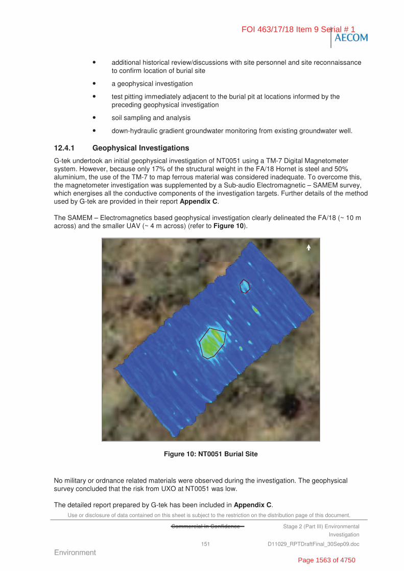
Use or disclosure of data contained on this sheet is subject to the restriction on the distribution page of this document.
Commercial in Confidence Stage 2 (Part III) Environmental
Investigation
151 D11029_RPTDraftFinal_30Sep09.doc
• additional historical review/discussions with site personnel and site reconnaissance to confirm location of burial site
• a geophysical investigation
• test pitting immediately adjacent to the burial pit at locations informed by the preceding geophysical investigation
• soil sampling and analysis
• down-hydraulic gradient groundwater monitoring from existing groundwater well.
12.4.1 Geophysical Investigations
G-tek undertook an initial geophysical investigation of NT0051 using a TM-7 Digital Magnetometer system. However, because only 17% of the structural weight in the FA/18 Hornet is steel and 50% aluminium, the use of the TM-7 to map ferrous material was considered inadequate. To overcome this, the magnetometer investigation was supplemented by a Sub-audio Electromagnetic – SAMEM survey, which energises all the conductive components of the investigation targets. Further details of the method used by G-tek are provided in their report Appendix C.
The SAMEM – Electromagnetics based geophysical investigation clearly delineated the FA/18 (~ 10 m across) and the smaller UAV (~ 4 m across) (refer to Figure 10).
Figure 10: NT0051 Burial Site
No military or ordnance related materials were observed during the investigation. The geophysical survey concluded that the risk from UXO at NT0051 was low.
The detailed report prepared by G-tek has been included in Appendix C.
FOI 463/17/18 Item 9 Serial # 1
Page 1563 of 4750

Use or disclosure of data contained on this sheet is subject to the restriction on the distribution page of this document.
Commercial in Confidence Stage 2 (Part III) Environmental
Investigation
152 D11029_RPTDraftFinal_30Sep09.doc
12.4.2 Soil Investigation
The soil investigation was undertaken on 16 and 17 October 2008 and comprised the following works:
• Five test pits (NT0051TP01 to NT0051TP05) were excavated to a maximum depth of 3.0 mbgl. The test pits were located surrounding the burial pits identified by the geophysical investigation.
The soil sampling locations are presented on Figure F19. Logs describing the subsurface soil profile are provided in Appendix H.
Fill Material
No fill materials were encountered during the intrusive investigation at NT0051. However, the intrusive investigation was focused on the area surrounding the known burial pits rather than within the burials. This approach was taken because of the occupational health and safety issues associated with exposure to the carbon fibre associated with the buried wreckages.
Natural Soil and Rock
The stratigraphy encountered comprised of homogenous, stiff red-brown silty clay from surface to a least 3.5 mbgl (maximum depth of investigation).
PID screening of soil samples did not suggest the presence of any volatiles with concentrations ranging from 1 to 1.7 ppm.
12.4.3 Groundwater Investigation
No groundwater monitoring wells were installed in the vicinity of NT0051. Bore 25, located approximately 342 m down hydraulic gradient (south west) of the burial site was sampled, on 10 November 2008, to assess potential groundwater contamination.
The standing water level measured at Bore 25 was 14.62 mbgl.
The NRETA supplied bore log for Bore 25 is provided in Appendix J. The location of Bore 25 is shown on Figure F19.
12.5 Laboratory Analytical Results
12.5.1 Soil Analysis
The soil samples from NT0051 were analysed for a range of CoPC including metals (NEPM 13), TPH, PAHs, MAH, VOC, SVOC, ammonia, nitrates, nitrites, explosives, beryllium, radium and PFOS.
The results of the soil sample laboratory analysis compared against the assessment criteria are summarised in Table T9. Laboratory analytical reports are provided in Appendix I.
Metals
Fifteen soil samples were analysed for metals. All sample concentrations were reported below NEPM HILF. Exceedances of the laboratory LOR and NEPM EILs where recorded for the following analytes:
• Vanadium concentrations above the LOR were reported in all samples. Eleven of the 15 samples exceeded the NEPM EIL of 50 mg/kg, with the highest concentrations measured at NT0051TP04 (1.5 to 2.0m) and NT0051TP05 (1.5 to 2.0m) of
FOI 463/17/18 Item 9 Serial # 1
Page 1564 of 4750
Use or disclosure of data contained on this sheet is subject to the restriction on the distribution page of this document.
Commercial in Confidence Stage 2 (Part III) Environmental
Investigation
153 D11029_RPTDraftFinal_30Sep09.doc
100 mg/kg. All results were within the background concentration range established for the Base.
• Manganese concentrations above the LOR were recorded in all samples. Two of the 15 samples exceeded the NEPM EIL of 500 mg/kg at NT0051TP01 (0.0 to 0.5 m) and NT0051TP02 (1.5 to 2.0 m) with 675 mg/kg and 524 mg/kg, respectively. All results were within the background concentration range established for the Base.
• The remaining metal and metalloid analytes (i.e. arsenic, beryllium, cadmium, chromium, cobalt, copper, lead and nickel) returned concentrations within the laboratory LOR or below the NEPM EIL.
Beryllium and Radium
Fifteen soil samples were analysed for Beryllium. All concentrations were reported below the laboratory LOR with the exception of NT0051TP01 (2.5 to 3.0 m) which recorded a concentration of 4 mg/kg which is below NEPM HILF and EILs.
Fifteen soil samples were analysed for Radium-226. Concentrations recorded ranged from 0.013 Bq/g to 0.043 Bq/g, with seven of the 15 soil samples exceeding the United Nations Scientific Committee on the Effects of Atomic Radiation reference value of 0.035 Bq/g.
TPH
Fifteen soil samples were analysed for TPH. All concentrations were reported below the laboratory LOR, with the exception of TPH C15-C28 and C29-C36 fractions in NT0051TP02 (1.5 to 2.0 m) (170 mg/kg and 110 mg/kg), NT0051TP04 (1.5 to 2.0 m) (210 mg/kg and 150 mg/kg) and NT0051TP03 (0 to 0.5 m) (120 mg/kg). All concentrations were less than the NSW EPA (1994) guideline of 1,000 mg/kg for TPH C15-C36 fraction.
VOCs
Two soil samples (equating to approximately 10%) were analysed for VOC. All concentrations were reported below the laboratory LOR and the site adopted criteria.
Fifteen soil samples were analysed for MAH. All concentrations were reported below the laboratory LOR and the site adopted criteria.
SVOCs
Two soil samples (equating to approximately 10%) were analysed for SVOC. All concentrations were reported below the laboratory LOR and the site adopted criteria.
Fifteen soil samples were analysed for PAH. All concentrations were reported below the laboratory LOR and the site adopted criteria.
Ammonia, Nitrates and Nitrites
Fifteen soil samples were analysed for ammonia. All concentrations were reported below the laboratory LOR and the site adopted criteria.
Fifteen soil samples were analysed for nitrates. All samples reported concentrations of nitrates above the laboratory LOR ranging from 0.281 mg/kg to 1.88 mg/kg.
Fifteen soil samples were analysed for nitrites. All samples reported concentrations of nitrites below the laboratory LOR, with the exception of NT0051TP04 (0 to 0.5m) which recorded 0.564 mg/kg.
FOI 463/17/18 Item 9 Serial # 1
Page 1565 of 4750

Use or disclosure of data contained on this sheet is subject to the restriction on the distribution page of this document.
Commercial in Confidence Stage 2 (Part III) Environmental
Investigation
154 D11029_RPTDraftFinal_30Sep09.doc
Explosives
Two soil samples were analysed for explosives. Concentrations were reported below the laboratory LOR.
Asbestos
Four soil samples were submitted for asbestos analysis. Asbestos fibres were not detected in any of the samples.
12.5.2 Groundwater Analysis
A groundwater sample was collected from Bore 25, which is located down hydraulic gradient of NT0051. The groundwater sample was analysed for a range of analytes including physical parameters, metals (NEPM 13), TPH, PAH, MAH, VOC, SVOC, ammonia, nitrates, nitrites, cations and anions, explosives, radium and PFOS.
The results of the groundwater sample laboratory analysis compared against the assessment criteria are included in Table T10. Laboratory analytical reports are provided in Appendix K. Figure F19 illustrates all sample locations.
Physical Parameters
Physical parameters encountered during the groundwater investigation are summarised in Table 42.
Table 42: NT0051 Groundwater Field Parameters, 10 November 2008
Field Parameters
Sample Id Relative SWL
(mAHD)
pH EC (μS/cm)
Redox Potential
(mV)
DO (mg/L)
Temp (ºC)
Bore 25 132.60 6.5 442 68 0.33 33.1
* Redox Potential (Eh) values have been converted to the SHE reference by adding 199mV to field measured redox (as per GHD,
2008). 150-800 mV indicates oxygen reduction.
The field parameter results are summarised as follows:
• pH measurement of 6.5 was recorded at Bore 25 which is within the ANZECC 2000 upland tropical rivers trigger level range of 6 to 7.5.
• EC was measured at 442 μS/cm (indicative of brackish water) in Bore 25 which exceeds the ANZECC (2000) Water Quality Targets for physical and chemical stressors in upland tropical rivers of 250 S/cm but is consistent with results obtained elsewhere on the Base.
• DO measurements indicate low oxygen levels in the groundwater.
• Redox potential measurement of 68 mV, indicating the water is reducing in nature.
Nutrients
Nutrients concentrations encountered during the groundwater investigation have been summarised below:
• Ammonia as N concentration at Bore 25 was less than the laboratory LOR.
• Nitrate concentration at Bore 25 was less than the laboratory LOR.
FOI 463/17/18 Item 9 Serial # 1
Page 1566 of 4750
Use or disclosure of data contained on this sheet is subject to the restriction on the distribution page of this document.
Commercial in Confidence Stage 2 (Part III) Environmental
Investigation
155 D11029_RPTDraftFinal_30Sep09.doc
• Nitrite concentration at Bore 25 was less than the laboratory LOR
• Total nitrogen (NOx) concentration at Bore 25 was less than the laboratory LOR.
Major Ions
Concentrations of major ions encountered during the groundwater investigation have been summarised below. All results were within the ANZECC 2000 stock water and irrigation water quality guidelines.
• Total anions concentration recorded at Bore 25 was 4.46 meq/L:
- Total alkalinity as CaCO3 concentrations at Bore 25 was 214 mg/L
- Chloride concentration at Bore 25 was 7 mg/L
- Sulphate as SO42- concentration at Bore 25 was less than the laboratory LOR
• Total cations concentration recorded at Bore 25 was 4.38 meq/L:
- Calcium concentration at Bore 25 recorded as 37 mg/L
- Magnesium concentration at Bore 25 recorded as 17 mg/L
- Sodium concentration at Bore 25 recorded as 26 mg/L
- Potassium concentration at Bore 25 was less than the laboratory LOR.
Metals
The groundwater sample collected from Bore 25 reported dissolved concentrations of metals less than the ANZECC 95% protection level trigger values for freshwater ecosystems and the NHMRC (2004) Australian Drinking Water – Health guidelines.
Radium
The groundwater sample collected from Bore 25 was analysed for Radium-226 (uranium series). Concentrations were less than the laboratory LOR of <0.03 bq/L-1.
TPH
The groundwater sample collected from Bore 25 was analysed for TPH. All concentrations were reported below the laboratory LOR.
VOCs
The groundwater sample collected from Bore 25 was analysed for VOCs. Concentrations were reported below the laboratory LOR.
The groundwater sample collected from Bore 25 was analysed for MAH. All concentrations were reported below the laboratory LOR.
SVOCs
The groundwater sample collected from Bore 25 was analysed for SVOCs. Concentrations were reported below the laboratory LOR.
The groundwater sample collected from Bore 25 was analysed for PAH. All concentrations were reported below the laboratory LOR.
FOI 463/17/18 Item 9 Serial # 1
Page 1567 of 4750
Use or disclosure of data contained on this sheet is subject to the restriction on the distribution page of this document.
Commercial in Confidence Stage 2 (Part III) Environmental
Investigation
156 D11029_RPTDraftFinal_30Sep09.doc
PFOS and PFOA
The groundwater sample collected from Bore 25 was analysed for PFOS and PFOA. The PFOS concentrations (0.2 μg/L) were above the laboratory LOR of 0.1 μg/L but less then the Minnesota Department of Health Risk guideline of 0.3 μg/L for Potable water.
12.6 Discussion of Site Contamination Issues
12.6.1 Contained Waste
Based on the SAMEM – Electromagnetics geophysical investigation, the FA/18 (~ 10 m across) and the smaller UAV (~ 4 m across) burial sites were clearly delineated. The buried wreckages are well covered and the area is fenced by a star pickets stock fence. The site is also signposted as ‘Contaminated Land’.
12.6.2 Soil Contamination
Soil analysis results from NT0051 were all within the NEPM HILF for industrial/commercial land use. A number of sample analysis results reported elevated metal concentrations, including vanadium and manganese, which exceed the NEPM EILs. The results are consistent with the expected background concentrations within the Base.
Radium-226 concentrations were recorded in exceedance of the United Nations Scientific Committee on the Effects of Atomic Radiation (2000) reference value of 0.035 Bq/g in seven of the 15 soil samples collected from greater than 1.0 mbgl. Hardege (2005) reported that radioactivity concentrations in Australian soils can naturally vary between 0.01 to 0.130 Bq/g. Therefore, the reported concentrations are considered to be indicative of background concentrations.
TPH C15-C36 fraction concentrations were recorded at three locations ranging from 195 mg/Kg to 385 mg/kg. These results suggest some anthropogenic impact has resulted from the burials. However the concentrations are within the NSW EPA (1994) guideline of 1,000 mg/kg and therefore are not considered to represent a risk to human health or the environment.
12.6.3 Groundwater Contamination
In general, the analysis results from the groundwater samples collected from Bore 25, down-hydraulic gradient of NT0051, were less than the adopted site assessment criteria. The only exception was as follows:
• Electrical conductivity measurements exceeded the ANZECC (2000) Water Quality Targets for physical and chemical stressors in upland tropical rivers but were generally consistent with levels reported for other areas across the Base.
• The PFOS concentration reported in Bore 25 was below the MDH (2007) for potable water but above the laboratory LOR. It is not clear whether the PFOS detection is a result of the NT0051 burial, or other historical activities in the vicinity of the bore.
12.7 Summary and Recommendations
12.7.1 Nature and Extent of Contamination
The findings of the Stage 2 (III) Investigations at NT0051 are as follows:
• Chemical contamination: Chemical contamination was not identified in soil or groundwater that exceeded the NEPM HILF for industrial/commercial land use and the ANZECC 95% protection trigger values, respectively. No explosive residues above detection limits or UXOs were detected during the intrusive investigation.
FOI 463/17/18 Item 9 Serial # 1
Page 1568 of 4750
Use or disclosure of data contained on this sheet is subject to the restriction on the distribution page of this document.
Commercial in Confidence Stage 2 (Part III) Environmental
Investigation
157 D11029_RPTDraftFinal_30Sep09.doc
PFOS impact was detected in groundwater, but not at concentrations above the adopted site assessment criteria.
• Chemicals of Concern:
- Nil.
• Buried Waste:
- Two burial areas were clearly delineated: one associated with a FA/18 (~ 10 m across) and a second associated with a smaller UAV (~ 4 m across).
- Both burials are well covered and the area delineated by a star picket stock fence. The site is also signposted as ‘Contaminated Land’.
• Soil Investigations:
- Contaminant concentrations identified in soil are not expected to pose an adverse impact to human health or the environment and are considered to be acceptable for continuing land use.
- All soil concentrations were reported below the NEPM HILF, EILs or other applicable assessment criteria.
• Groundwater Investigation:
- Contaminant concentrations identified in groundwater are not expected to pose an adverse impact to human health and are considered to be acceptable for continuing commercial/industrial land use.
- EC measurements exceeded the ANZECC (2000) Water Quality Targets for physical and chemical stressors in upland tropical rivers of 250 S/cm but were generally consistent with levels reported in previous groundwater monitoring events around the Base.
- PFOS was detected in Bore 25 at a concentration above the laboratory LOR but below the adopted site assessment criteria. It is unclear whether the PFOS detected is an anomaly (i.e. false positive) or the result of the burial site or other historical activities (possibly training) in the vicinity of the bore.
- All other groundwater concentrations of CoPC (i.e. metals, radium, TPH, PAH, MAH, VOC and SVOC) were below the adopted assessment criteria.
12.7.2 Risks Identified
Appendix L summarises the assessment of risk associated with the identified contamination at NT0051. The results of the Stage 2 (III) risk assessment are summarised following.
• NT0051 – Low Risk Band with a Risk Priority score of 201 based on the sites remote location to occupied areas and that the site is currently managed (i.e. fenced and sign posted).
12.7.3 Site Specific Recommendations
Contaminant concentrations in the soil and groundwater at NT0051 are not expected to pose an adverse impact to human health or ecological receptors provided that the area is adequately maintained. The following recommendations have been made in relation to NT0051:
• maintain the existing stock fence to restrict public access
• maintain track into site without drawing undue attention to the area
FOI 463/17/18 Item 9 Serial # 1
Page 1569 of 4750
Use or disclosure of data contained on this sheet is subject to the restriction on the distribution page of this document.
Commercial in Confidence Stage 2 (Part III) Environmental
Investigation
158 D11029_RPTDraftFinal_30Sep09.doc
• replace existing signage with new signs identifying the general risk associated with the burial
• enter correct coordinates of the burial site on the Base CSR
• include NT0051 on the site specific CEMP (being developed separately as part of the Stage 2 (III) Investigations
• include burial area on the Base Asbestos Register, due to the materials such as carbon fibre contained within the buried aircraft.
FOI 463/17/18 Item 9 Serial # 1
Page 1570 of 4750
Use or disclosure of data contained on this sheet is subject to the restriction on the distribution page of this document.
Commercial in Confidence Stage 2 (Part III) Environmental
Investigation
159 D11029_RPTDraftFinal_30Sep09.doc
13.0 Site Investigation – T10 Old Pool Dumping Site
13.1 Area Description
T10 (Old Pool Dumping Site) was identified during the Stage 2 (III) Investigation and added to the scope of the original investigation described by the SOR. The area was reported to have been used as a disposal site over a number of years by both Defence and civilians up until 1997 when access was restricted.
It is believed the site was initially used to dispose of the old Base swimming pool (principally concrete and steel debris) which had broken up during a flooding event. Following from this, it appears that the area was made available for general rubbish disposal for RAAF Tindal, including the Range Produce from the .22 Rifle Range (pers comm. FLT SGT Des Brennan, 15 October 2008).
There is evidence to suggest the area was originally a scrape that was subsequently filled by the waste materials.
Site observations identified waste materials including discarded pool material (i.e. concrete and steel debris) as well as other domestic waste including medicine bottles, corrugated tin sheets, mower parts, car parts, etc.. Part of the landfill area was covered in top soil and a mat of the Passiflora foetida (Stinking Passion Flower), which is a naturalised vine species located throughout the Northern Territory.
The location of the area of interest is described in Table 43 and shown in Figure F20.
Table 43: T10 Investigation Location
Coordinates* Landfill No. Description of Area
NW Corner SE Corner
Size (ha)
T10 main Located south of the Stuart Highway approximately 2.2 km from the RAAF Tindal Turnoff and 246 m south from the RAAF Tindal Boundary Fence.
-14.480746ºS
132.374498ºE
-14.483454ºS
132.377516ºE
~3.6
T10 smaller area Located 30 m north of the main T10 landfill area.
-14.479971ºS
132.374222ºE
-14.480903ºS
132.375460ºE
~0.4
* Latidude/Longitude DATUM WGS 84
Photographs were taken of the area of interest and are presented in the Plates Section of this report (Plate 87 to Plate 101).
The T10 (Old Pool Dumping Site) was bounded by:
• native bushland to the south
• native bushland to the west
• RAAF Tindal boundary and the Stuart Highway to the north
• native bushland and RAAF Tindal administration area to the east.
FOI 463/17/18 Item 9 Serial # 1
Page 1571 of 4750
Use or disclosure of data contained on this sheet is subject to the restriction on the distribution page of this document.
Commercial in Confidence Stage 2 (Part III) Environmental
Investigation
160 D11029_RPTDraftFinal_30Sep09.doc
13.2 Objectives of the Stage 2 Investigation
To meet the overall objective of the Stage 2 (III) Investigation of defining the ‘true risks’ to Defence of potential contamination, T10 Old Pool Dumping Site were investigated to:
• Confirm location of the reported landfill area by undertaking additional site reconnaissance and stakeholder consultation.
• Delineate the vertical and lateral extent of landfill material and chemical contamination (to the extent practical).
• Quantify and characterise waste material within landfill.
• Measure concentrations of contaminants within the soils.
• Identify potential human health and ecological receptors.
• Assess the potential for waste materials and/or impacted soils to leach contaminants of concern into groundwater and nearby receiving waters.
13.3 Historical Information, Previous Investigations and Potential Chemicals of Concern
13.3.1 Previous Reports
T10 (Old Pool Dumping Area) has not been subject to previous assessment.
13.3.2 Historical Aerial Photographs
A limited review of the available historical aerial photographs at the office of DS-Tindal was undertaken during the Stage 2 (III) Investigations for the T10 landfill to assist in identifying the investigation area.
The aerial photographs revealed that the area was cleared with native bushland surrounding.
13.3.3 Potential Chemical of Concern
Based on the available historical information, the potential chemicals of concern at T10 old pool dumping area included:
• heavy metals (i.e. arsenic, barium, beryllium, cadmium, chromium, copper, manganese, nickel, lead, mercury, vanadium and zinc) from scrap steel waste
• nitrated compounds and ammonia from reported ordnance disposal
• hydrocarbons (TPH, BTEX, PAH, MAH and chlorinated hydrocarbons) because of the unknown nature of the land filled material
• asbestos from disused building materials and rubble.
13.4 Stage 2 (III) Intrusive Investigation
The Stage 2 (III) intrusive investigation at T10 (Old Pool Dumping Area) consisted of:
• a geophysical investigation
• test pitting at locations informed by the preceding geophysical investigation
• soil sampling and analysis.
FOI 463/17/18 Item 9 Serial # 1
Page 1572 of 4750
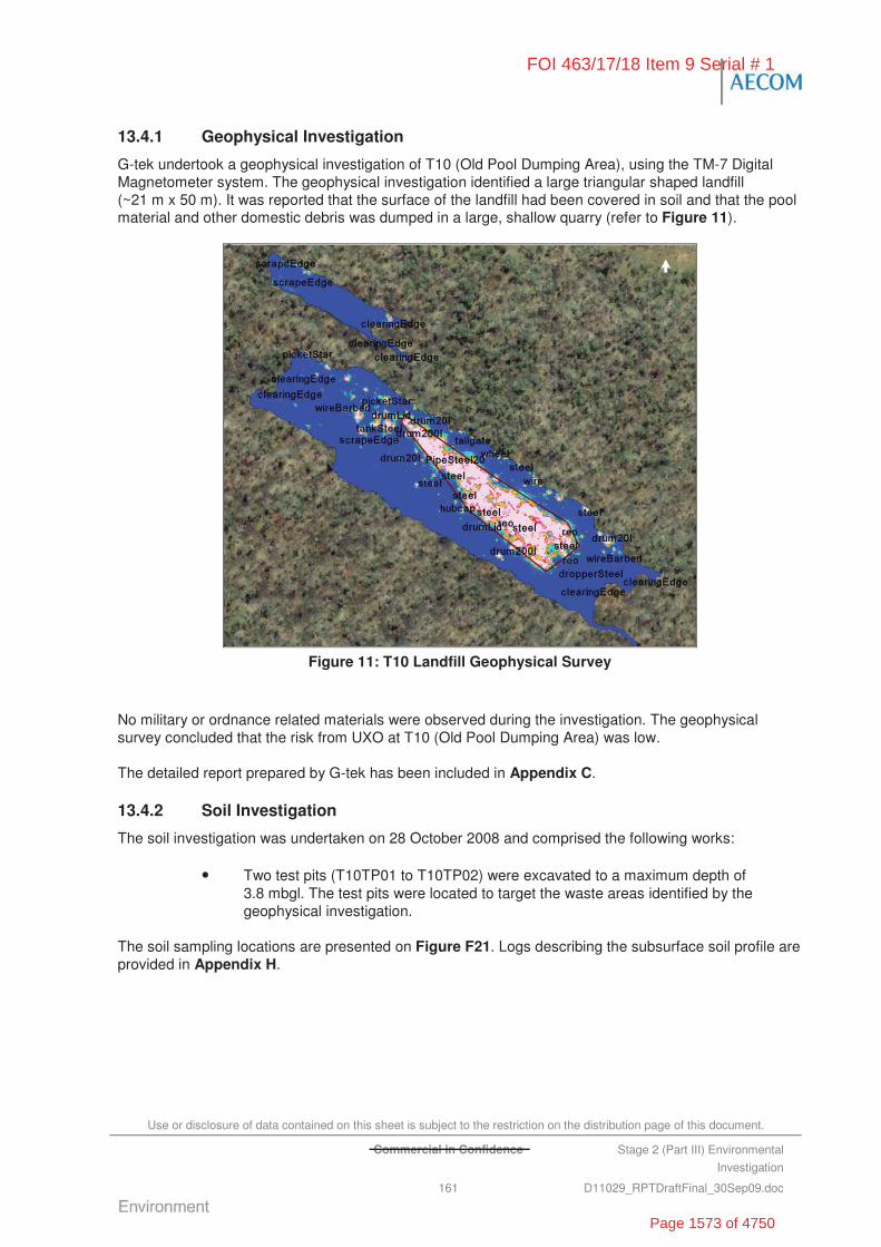
Use or disclosure of data contained on this sheet is subject to the restriction on the distribution page of this document.
Commercial in Confidence Stage 2 (Part III) Environmental
Investigation
161 D11029_RPTDraftFinal_30Sep09.doc
13.4.1 Geophysical Investigation
G-tek undertook a geophysical investigation of T10 (Old Pool Dumping Area), using the TM-7 Digital Magnetometer system. The geophysical investigation identified a large triangular shaped landfill (~21 m x 50 m). It was reported that the surface of the landfill had been covered in soil and that the pool material and other domestic debris was dumped in a large, shallow quarry (refer to Figure 11).
Figure 11: T10 Landfill Geophysical Survey
No military or ordnance related materials were observed during the investigation. The geophysical survey concluded that the risk from UXO at T10 (Old Pool Dumping Area) was low.
The detailed report prepared by G-tek has been included in Appendix C.
13.4.2 Soil Investigation
The soil investigation was undertaken on 28 October 2008 and comprised the following works:
• Two test pits (T10TP01 to T10TP02) were excavated to a maximum depth of 3.8 mbgl. The test pits were located to target the waste areas identified by the geophysical investigation.
The soil sampling locations are presented on Figure F21. Logs describing the subsurface soil profile are provided in Appendix H.
FOI 463/17/18 Item 9 Serial # 1
Page 1573 of 4750
Use or disclosure of data contained on this sheet is subject to the restriction on the distribution page of this document.
Commercial in Confidence Stage 2 (Part III) Environmental
Investigation
162 D11029_RPTDraftFinal_30Sep09.doc
Fill Material
The main landfill area was covered in a reworked red-brown sandy silty clay cap and a dense mat of stinking passion flower (Passiflora foetida) vine. Observations during the initial site walk over and subsequent intrusive investigation identified discarded pool construction material and domestic debris, including potential ACM, tyres, wood, concrete slabs, burnt fire extinguishers, mower, car parts etc.. The soil material covering the landfill area is consistent with the naturally occurring surface soils encountered across the area.
Natural Soil and Rock
The stratigraphy encountered at T10 (Pool Disposal Area) comprised of red-brown sandy silty clay at the surface, overlying red-brown clayey sand or sandy clay, with increasing grey limestone gravel at 3.0 to 3.5 mbgl.
PID screening of soil samples did not suggest the presence of volatiles with concentrations ranging from 0.0 to 0.6 ppm.
13.4.3 Groundwater Investigation
Groundwater was not assessed as part of the Stage 2 (III) Investigations at T10 (Old Pool Dumping Area).
13.5 Laboratory Analytical Results
13.5.1 Soil Analysis
The soil samples at T10 (Old Pool Dumping Area) were analysed for a range of CoPC including metals (NEPM 13), TPH, PAHs, MAH, VOC, SVOC, ammonia, nitrates, nitrites and asbestos.
The results of the soil sample laboratory analysis compared against the assessment criteria are summarised in Table T11. Laboratory analytical reports are provided in Appendix I. Figure F21 illustrates all sample locations.
Metals
Six soil samples were analysed for metals. All sample concentrations were reported below NEPM HILF. Exceedances of the laboratory LOR and/or NEPM EILs were recorded for the following analytes:
• Vanadium concentrations equal to the NEPM EIL criteria of 50 mg/kg, but within the background concentration range established for the Base, were reported at T10TP02 (1.9 to 2.0 m). The remaining soil samples recorded vanadium concentrations above the LOR ranging from 27 mg/kg to 40 mg/kg.
• Zinc concentrations (334 mg/kg) exceeding the NEPM EIL criteria of 200 mg/kg were reported at T10TP02 (1.9 to 2.0 m). The remaining samples recorded concentrations above the LOR ranging from 20 mg/kg to 83 mg/kg.
• The remaining metal and metalloid analytes (i.e. arsenic, barium, beryllium, cadmium, chromium, cobalt, copper, lead, manganese, mercury and nickel) returned concentrations within the laboratory LOR or below the NEPM EIL.
TPH
Six soil samples were analysed for TPH. All concentrations were reported below the laboratory LOR and the site adopted criteria.
FOI 463/17/18 Item 9 Serial # 1
Page 1574 of 4750
Use or disclosure of data contained on this sheet is subject to the restriction on the distribution page of this document.
Commercial in Confidence Stage 2 (Part III) Environmental
Investigation
163 D11029_RPTDraftFinal_30Sep09.doc
VOCs
One soil sample (equating to approximately 10%) was analysed for VOCs. All concentrations were reported below the laboratory LOR the site adopted criteria.
Six soil samples were analysed for MAH. All concentrations were reported below the laboratory LOR the site adopted criteria.
SVOCs
One soil sample (equating to approximately 10%) was analysed for SVOCs. All concentrations were reported below the laboratory LOR the site adopted criteria.
Six soil samples were analysed for PAH. All concentrations were reported below the laboratory LOR the site adopted criteria.
Ammonia, Nitrates and Nitrites
Six soil samples were analysed for ammonia. All concentrations were reported below the laboratory LOR the site adopted criteria.
Six soil samples were analysed for nitrates. All samples reported concentrations of nitrates above the LOR ranging from 0.64 mg/kg to 9.29 mg/kg.
Six soil samples were analysed for nitrites. Three of the six samples reported concentrations of nitrites above the laboratory LOR ranging from 0.218 mg/kg to 0.421 mg/kg.
Asbestos
Two soil samples were analysed for asbestos. Asbestos fibres were not detected in the samples.
13.6 Discussion of Site Contamination Issues
13.6.1 Contained Waste
Based on the geophysical investigation and the limited intrusive (test pitting) investigation at the T10 (Old Pool Dumping Area) there was widespread evidence that the area has previously been used for the dumping ground of miscellaneous materials.
The footprint (exclusive of scattered waste) of the primary landfill area was estimated at 5,832 m2 with an estimated contained waste volume of 8,748 m3, based on a maximum depth of fill to 1.5 mbgl.
The waste contained by the landfill is broadly characterised as comprising of discarded pool construction materials (i.e. concrete and steel debris) and other domestic waste including medicine bottles, corrugated tin sheets, mower parts, car parts, potential ACM, a number of 205 L steel drums, fire extinguishers and metal fragments. Surface scatters of miscellaneous waste materials were also noted across the broader T10 (Old Pool Disposal Area).
13.6.2 Soil Contamination
Soil analysis results from across T10 (Old Pool Dumping Area) were within the NEPM HILF for industrial/commercial land use. However the area is located at the boundary of the Base in native bushland and as such the more stringent NEPM EIL guidelines are considered applicable. Elevated metals concentrations, including vanadium and zinc, which exceeded the NEPM EILs were reported at T10TP02 (1.9 to 2.0 m). While the vanadium result is consistent with background concentrations established for the Base, the Zinc concentration is considered likely a result of anthropogenic sources.
FOI 463/17/18 Item 9 Serial # 1
Page 1575 of 4750
Use or disclosure of data contained on this sheet is subject to the restriction on the distribution page of this document.
Commercial in Confidence Stage 2 (Part III) Environmental
Investigation
164 D11029_RPTDraftFinal_30Sep09.doc
Asbestos contamination was not reported by the soil samples collected as part of the investigations. However, potential ACM (i.e. fibrous cement sheeting and pipes) were observed throughout T10 (Old Pool Dumping Area). Therefore the presence of asbestos cannot be discounted.
13.7 Summary and Recommendations
13.7.1 Nature and Extent of Contamination
The findings of the Stage 2 (III) Investigations at T10 are as follows:
• Chemical contamination: Chemical contamination was not identified in soil in concentrations that exceeded the NEPM HILF for industrial/commercial land use. No explosive residues or UXOs were detected during the intrusive investigation or the preceding geophysical investigation. Potential ACM was visually noted across the area. Buried waste was identified in a central location within the area of interest.
• Chemicals of Potential Concern:
- Heavy metals – Zinc
- Asbestos (potential ACM).
• Buried Waste:
- Miscellaneous waste materials were observed to be scattered across the surface of the area of interest.
- Buried waste was identified over an area of 5,832 m2 with an estimated volume of 8,748 m3, based on a maximum depth of fill to 1.5 mbgl.
• Soil Investigations:
- Contaminant concentrations identified in the soil are not expected to pose an adverse impact to human health and are considered to be acceptable for continuing commercial/industrial land use.
13.7.2 Risks Identified
Appendix L summarises the assessment of risks associated with the identified contamination at T10 (Old Pool Disposal Area). The results of the Stage 2 (III) risk assessment are summarised following:
• T10 – High Risk Band with a Risk Priority score of 168 based on exposure of contractors to potential ACM if conducting intrusive works (OHS dimension) and human contact from potential exposure to surface ACM. In addition, a Medium Risk Band with a Risk Priority score of 177 based on the potential for Defence personnel and contractors to have contact with landfill objects including star pickets, drums, wire etc. exposed at the surface (i.e. OHS dimension).
13.7.3 Site Specific Recommendations
T10 (Old Pool Dumping Area) is located within the boundary of RAAF Tindal, near the Stuart Highway. Public access to this area has occurred in the past; however, since 1997 access to the area has reportedly been restricted (possibly with limited effectiveness). The following recommendations have been made in relation to T10 (Old Pool Dumping Area),
• restrict access to the area of interest (i.e. fencing and sign post) and include on the Base Asbestos Register
• remove suspected ACM from the surface by ‘Emu Pick’ (manual collection), completed by an appropriately licensed contractor, from across the landfill footprint
FOI 463/17/18 Item 9 Serial # 1
Page 1576 of 4750
Use or disclosure of data contained on this sheet is subject to the restriction on the distribution page of this document.
Commercial in Confidence Stage 2 (Part III) Environmental
Investigation
165 D11029_RPTDraftFinal_30Sep09.doc
• dispose of ACM to offsite licensed landfill facility
• remove surface waste material from within and around the dumping area including razor wire, car parts, small appliances, medicine bottles and construction and demolition waste
• fence the entire landfill footprint using a stock fence to restrict public access (without drawing undue attention)
• erect signage identifying general risk associated with area
• include T10 (Old Pool Dumping Area) in the site specific CEMP, developed as part of the Stage 2 (III) Investigations.
FOI 463/17/18 Item 9 Serial # 1
Page 1577 of 4750

Use or disclosure of data contained on this sheet is subject to the restriction on the distribution page of this document.
Commercial in Confidence Stage 2 (Part III) Environmental
Investigation
166 D11029_RPTDraftFinal_30Sep09.doc
“This page has been left blank intentionally”
FOI 463/17/18 Item 9 Serial # 1
Page 1578 of 4750
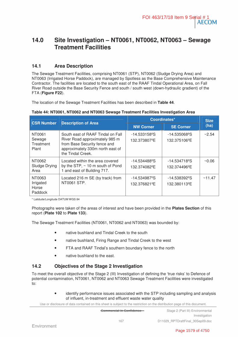
Use or disclosure of data contained on this sheet is subject to the restriction on the distribution page of this document.
Commercial in Confidence Stage 2 (Part III) Environmental
Investigation
167 D11029_RPTDraftFinal_30Sep09.doc
14.0 Site Investigation – NT0061, NT0062, NT0063 – Sewage Treatment Facilities
14.1 Area Description
The Sewage Treatment Facilities, comprising NT0061 (STP), NT0062 (Sludge Drying Area) and NT0063 (Irrigated Horse Paddock), are managed by Spotless as the Base Comprehensive Maintenance Contractor. The facilities are located to the south east of the RAAF Tindal Operational Area, on Fall River Road outside the Base Security Fence and south / south west (down-hydraulic gradient) of the FTA (Figure F22).
The location of the Sewage Treatment Facilities has been described in Table 44.
Table 44: NT0061, NT0062 and NT0063 Sewage Treatment Facilities Investigation Area
Coordinates* CSR Number Description of Area
NW Corner SE Corner
Size (ha)
NT0061 Sewage Treatment Plant
South east of RAAF Tindal on Fall River Road approximately 985 m from Base Security fence and approximately 330m north east of the Tindal Creek.
-14.533158ºS
132.373807ºE
-14.535068ºS
132.375106ºE
~2.54
NT0062 Sludge Drying Area
Located within the area covered by the STP, ~ 10 m south of Pond 1 and east of Building 717.
-14.534488ºS
132.374082ºE
-14.534718ºS
132.374496ºE
~0.06
NT0063 Irrigated Horse Paddock
Located 216 m SE (by track) from NT0061 STP.
-14.534987ºS
132.376821ºE
-14.538392ºS
132.380113ºE
~11.47
* Latidude/Longitude DATUM WGS 84
Photographs were taken of the areas of interest and have been provided in the Plates Section of this report (Plate 102 to Plate 133).
The Sewage Treatment Facilities (NT0061, NT0062 and NT0063) was bounded by:
• native bushland and Tindal Creek to the south
• native bushland, Firing Range and Tindal Creek to the west
• FTA and RAAF Tindal’s southern boundary fence to the north
• native bushland to the east.
14.2 Objectives of the Stage 2 Investigation
To meet the overall objective of the Stage 2 (III) Investigation of defining the ‘true risks’ to Defence of potential contamination, NT0061, NT0062 and NT0063 Sewage Treatment Facilities were investigated to:
• identify performance issues associated with the STP including sampling and analysis of influent, in-treatment and effluent waste water quality
FOI 463/17/18 Item 9 Serial # 1
Page 1579 of 4750

Use or disclosure of data contained on this sheet is subject to the restriction on the distribution page of this document.
Commercial in Confidence Stage 2 (Part III) Environmental
Investigation
168 D11029_RPTDraftFinal_30Sep09.doc
• measure concentrations of contaminants within soil in the irrigation paddock and sludge drying area
• identify potential human health and ecological receptors
• recommend operational improvements, noting the location of the facility close to Tindal Creek.
14.3 Historical Information, Previous Investigations and Potential Chemicals of Concern
14.3.1 Previous Reports
The Landfill/Burial Sites Stage 1 Environmental Investigation (Stage 1 EI) prepared by ERM (2007b) included an assessment of the status of NT0061, NT0062 and NT0063 Sewage Treatment Facilities.
The Stage 1 EI (ERM, 2007b) identified that the STP (NT0061) consisted of two ponds, each with a capacity of approximately 8.6 ML, which treat effluent via primary sedimentation. The ponds are reportedly no longer chlorinated due to the Northern Territory Government regulations. Chlorination of the ponds reportedly ceased when the waste water levels were found to meet the ANZECC Australian Water Quality Guidelines (1992) for irrigation purposes. The Stage 1 EI (ERM, 2007b) also reported that waste water in the ponds has been recorded as having significant coliform levels (around 20,000 CFU/L); therefore it is uncertain whether the water would meet current ANZECC guideline levels for irrigation.
Prior to the site’s use as a Sewage Treatment Facility the area was managed bushland and grazing areas.
Birds, including ducks and local water birds swimming on and drinking from the ponds have previously died from botulism, suggesting that the pond treatment processes may not be adequately treating the pathogens and microbiological activity in the waste water.
It was also reported by SKM (2000) that the liner to the second pond became detached in approximately 1997 and was repaired. Soil analysis was reportedly undertaken below the liner and the ponds found to be working effectively (although no record of testing and results were sighted).
The Stage 1 EI (ERM, 2007b) concluded that the Sewage Treatment Facilities (including NT0061, NT0062 and NT0063) posed a medium risk based on risk to the environment (particularly water birds) and groundwater reliant ecosystems.
ERM (2007b) indentified the STP as a priority classification and recommended the following management options, in the context of the ongoing and current use (i.e. Priority 3).
• Fencing and signage to warn that the water is not suitable for drinking or dermal contact
• Standard Operating Procedures for the STP to include reference to areas that should not be accessed under any circumstances.
• Implement a groundwater monitoring program specifically targeting the Sewage Treatment Facilities, including installation of at least two groundwater monitoring bores (or use of current bores if suitable), one up-gradient and one downgradient.
• Implementation of a management plan for the Sewage Treatment Facilities including regular inspections and maintenance of the liners and regular testing (e.g. weekly) of treated water to ensure it is suitable for irrigation use (according to the ANZECC guidelines).
FOI 463/17/18 Item 9 Serial # 1
Page 1580 of 4750
Use or disclosure of data contained on this sheet is subject to the restriction on the distribution page of this document.
Commercial in Confidence Stage 2 (Part III) Environmental
Investigation
169 D11029_RPTDraftFinal_30Sep09.doc
14.3.2 Potential Chemical of Concern
Based on the available historical information, the potential chemicals of concern at NT0061, NT0062 and NT0063 include:
• heavy metals (including arsenic, copper, cadmium, lead, mercury, nickel, tin and zinc)
• nitrates and nutrients (phosphate and ammonium)
• faecal coliforms, pathogens and viruses.
At RAAF Tindal, waste water from operational activities (including aircraft and ground support equipment maintenance) may also enter the STP and potentially impact effluent water quality. Therefore, the CoPC also included:
• TPH/PAH/MAH
• VOC/SVOC
• PFOS/PFOA.
14.4 Stage 2 (III) Investigation
The Stage 2 (III) Investigations at NT0061, NT0062 and NT0063 (Sewage Treatment Facilities) consisted of:
• a review the RAAF Tindal STP operations
• collection and analysis of samples of influent, in-treatment and effluent waste water
• confirmation of the integrity of STP infrastructure (anecdotal review initially – formal assessment may be required pending the outcome of the anecdotal review)
• test pitting across the footprint of the sludge drying area and irrigation paddock
• soil sampling and analysis
• groundwater sample collection and analysis from existing down-hydraulic gradient groundwater monitoring wells (i.e. Bore 10, Bore 11 and Bore 20).
14.4.1 Review of STP Operations
NT0061 STP consists of two settling ponds (each with a capacity of approximately 8.6 ML) connected in series (Plate 105). Either pond (east or west) can be the primary treatment pond, but flow is normally directed front to back in the east pond (Pond 1) then front to back in the west pond (Pond 2). Water can be diverted to either single pond while the other is de-watered and sludge removal is performed (refer to Figure F22). On-site interviews with Spotless site personnel reported that sludge removal has not occurred in the last 10 years.
Sludge removed from the ponds is placed in a small holding area (unlined) located directly to the south of Pond 1 (NT0062). SKM (2005) identified that the unlined sludge pit is used for dumping of excess sludge, which is removed from site by Waste Master. During the second site visit in December 2008, AECOM noted that the material being dumped at this area was not just sludge from the STP. Rather, it appeared that hydrocarbon contaminated material, with a strong odour, was being dumped in the holding area (Plate 113 and Plate 122).
The configuration of the pond system at RAAF Tindal suggests a facultative pond design, also known as an oxidation pond. In this type of pond system the upper portion of the pond waters are characterised by
FOI 463/17/18 Item 9 Serial # 1
Page 1581 of 4750
Use or disclosure of data contained on this sheet is subject to the restriction on the distribution page of this document.
Commercial in Confidence Stage 2 (Part III) Environmental
Investigation
170 D11029_RPTDraftFinal_30Sep09.doc
an aerobic surface zone which grades to an anaerobic bottom. This type of pond system is common and would be expected to perform well in a warm sunny climate, such as experienced at RAAF Tindal.
Based on an interview with the Base CMC, Spotless, the system averages approximately 162 kilolitres (kL) of flow per day during the dry season and 324 to 486 kL per day during the wet season. These estimates were provided based on the pump flow potentials required at the treatment plant headwork’s (pers. comms. Geoff Meehan, Spotless CMC, October 2008)
Within the pond heavy, solid material is allowed to settle out of the flow. The water that flows beneath a skimmer allows additional/slow settling to occur in the quiescent backwater of the pond(s). Bubbling was noted in both the front and back section of Pond 1. The front of Pond 1 was also noted to release foamy scum to the surface in small (0.5 m2) areas, accompanied by bubbling. All of these occurrences are characteristics of the presence of anaerobic digestion similar to that common in a septic tank system.
Five pump stations, located across the RAAF Tindal OA, pump raw sewage into the STP inlet. Prior to release to the oxidation ponds, influent passes through a small bar screen with approximately 2 m2 of area. This small bar screen commonly clogs and allows unscreened water to directly enter Pond 1 via surface sheet flow. This equates to adding what is normally easily removed BOD back to the treatment process. This can in turn reduce the overall capacity of the pond system.
The solid waste that accumulates on the small bar screen is manually removed (raked) on a daily basis by Spotless and incinerated in a small, modified 205 L drum incinerator located nearby (Plate 102 and Plate 103).
The total retention time for the two sewage treatment ponds is six days. SKM (2005) reported that the first quarter of the two ponds are concrete lined and then plastic lined in the remaining sections. A skimming board rakes floatables to one end.
The settlement process is followed by the use of agricultural/industrial aeration type sprinklers to irrigate the nearby horse paddocks (NT0063). A 400 m x 220 m (8.8 ha) grassed area is irrigated by a total of eight such sprinklers, operating two per cycle. The total area of the horse paddocks is 11.5 ha.
A number of horses (approximately 12 to 18) were observed grazing on the irrigated paddocks (NT0063). Drinking water is supplied to the horses from Bore 20, located directly south of the STP. It is understood that the horses are owned by Defence personnel and their families who regularly use the paddocks for agistment and riding activities.
14.4.2 Soil Investigation
The soil investigation was undertaken on 27 October 2008 and comprised the following works:
• Six test pits (NT0062TP01 to NT0062TP02 and NT0063TP01 to NT0063TP04) were excavated to a maximum depth of 0.5 mbgl. The test pits were located to provide general coverage across the sludge disposal area (NT0062) and irrigated horse paddock (NT0063), respectively.
The soil sampling locations are presented on Figure F23. Logs describing the subsurface soil profile are provided in Appendix H.
In addition, two soil grab samples from the top 10 cm were collected from NT0062 Sludge Drying Area on 30 April 2009. Spotless personnel brought to our attention that sludge from FF1 retention pond had recently been dumped at the Sludge Dying Area. Strong odour from the drying area and black soil was noted during inspection of the facility (Plate 121). Also a dead bird was also noted in the area (Plate 122).
FOI 463/17/18 Item 9 Serial # 1
Page 1582 of 4750

Use or disclosure of data contained on this sheet is subject to the restriction on the distribution page of this document.
Commercial in Confidence Stage 2 (Part III) Environmental
Investigation
171 D11029_RPTDraftFinal_30Sep09.doc
Fill Material
Fill material was not encountered at the irrigated horse paddock (NT0063). Fill material encountered at the sludge drying area (located south of Pond 1) consisted of dark brown organic materials with a strong odour. Some anthropogenic waste (i.e. plastics and toilet deodorisers) were also noted.
Natural Soil and Rock
The stratigraphy encountered at NT0062 (sludge drying area) consisted of dark brown sandy clayey silt to 0.5 mbgl. Strong odours were observed at NT0062TP01 which returned PID readings of 359 ppm at the surface (0.0 to 0.1 m) and 335 ppm at depth (0.4 to 0.5 m). No odours were detected in NT0062TP02, with PID levels ranging from 0.8 to 1.5 ppm.
The stratigraphy encountered at NT0063 (irrigated horse paddock) consisted of homogenous brown sandy clayey silt from the surface to approximately 0.15 mbgl, overlying reddish brown silty clay at depth (0.3 m). PID screening did not indicate the presence of volatiles with concentrations ranging from 0.0 to 0.4 ppm.
Rock was not encountered during the test pitting as the primary focus was on the shallow surface soils.
14.4.3 Groundwater Investigation
The groundwater investigation was undertaken on 11 November 2008. Groundwater wells were not installed as part of the investigations. Three existing bores (Bore 10, Bore 11 and Bore 20) located down hydraulic gradient of the Sewage Treatment Facilities were sampled.
The standing water levels in Bore 10 and Bore 11 were 7.53 m and 5.85 m, respectively. Bore 20 is an extraction bore and as such SWL was not collected.
14.5 Laboratory Analytical Results
14.5.1 Soil Analysis
The soil samples at NT0062 and NT0063 were analysed for a range of CoPC including metals (NEPM 13), TPH, PAHs, MAH, VOC, SVOC, ammonia, nitrates, nitrites, nutrients, and microbiological parameters (total coliforms and faecal coliforms). It should be noted that the soil samples collected from NT0062 (Sludge Drying Area) and NT0063 (Irrigated Horse Paddock) were labelled incorrectly during the field program.
In addition, two grab samples collected on 30 April 2009 from NT0062 were sampled for CoPC including metals (As, Cd, Cr, Cu, Pb, Ni, Zn and Hg) and TPH.
The results of the soil sample laboratory analysis compared against the assessment criteria are summarised in Table T12. Laboratory analytical reports are provided in Appendix I. The soil sampling locations are presented on Figure F23.
Metals
Sixteen soil samples (four from the sludge drying area and 12 from the irrigated horse paddock) were analysed for metals. All sample concentrations were reported below NEPM HILF. Exceedances of the laboratory LOR and /or NEPM EILs were recorded for the following analytes:
• Vanadium concentrations above the LOR were reported in all samples with reported concentrations ranging from 29 mg/kg to 101 mg/kg. Eleven of the 16 soil samples exceeded the NEPM EIL of 50 mg/kg. All the results were within the background concentration range established for the Base.
FOI 463/17/18 Item 9 Serial # 1
Page 1583 of 4750
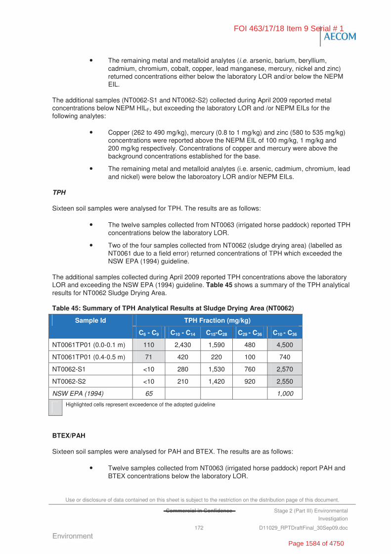
Use or disclosure of data contained on this sheet is subject to the restriction on the distribution page of this document.
Commercial in Confidence Stage 2 (Part III) Environmental
Investigation
172 D11029_RPTDraftFinal_30Sep09.doc
• The remaining metal and metalloid analytes (i.e. arsenic, barium, beryllium, cadmium, chromium, cobalt, copper, lead manganese, mercury, nickel and zinc) returned concentrations either below the laboratory LOR and/or below the NEPM EIL.
The additional samples (NT0062-S1 and NT0062-S2) collected during April 2009 reported metal concentrations below NEPM HILF, but exceeding the laboratory LOR and /or NEPM EILs for the following analytes:
• Copper (262 to 490 mg/kg), mercury (0.8 to 1 mg/kg) and zinc (580 to 535 mg/kg) concentrations were reported above the NEPM EIL of 100 mg/kg, 1 mg/kg and 200 mg/kg respectively. Concentrations of copper and mercury were above the background concentrations established for the base.
• The remaining metal and metalloid analytes (i.e. arsenic, cadmium, chromium, lead and nickel) were below the laboroatory LOR and/or NEPM EILs.
TPH
Sixteen soil samples were analysed for TPH. The results are as follows:
• The twelve samples collected from NT0063 (irrigated horse paddock) reported TPH concentrations below the laboratory LOR.
• Two of the four samples collected from NT0062 (sludge drying area) (labelled as NT0061 due to a field error) returned concentrations of TPH which exceeded the NSW EPA (1994) guideline.
The additional samples collected during April 2009 reported TPH concentrations above the laboratory LOR and exceeding the NSW EPA (1994) guideline. Table 45 shows a summary of the TPH analytical results for NT0062 Sludge Drying Area.
Table 45: Summary of TPH Analytical Results at Sludge Drying Area (NT0062)
TPH Fraction (mg/kg) Sample Id
C6 - C9 C10 - C14 C15-C28 C29 - C36 C10 - C36
NT0061TP01 (0.0-0.1 m) 110 2,430 1,590 480 4,500
NT0061TP01 (0.4-0.5 m) 71 420 220 100 740
NT0062-S1 <10 280 1,530 760 2,570
NT0062-S2 <10 210 1,420 920 2,550
NSW EPA (1994) 65 1,000
Highlighted cells represent exceedence of the adopted guideline
BTEX/PAH
Sixteen soil samples were analysed for PAH and BTEX. The results are as follows:
• Twelve samples collected from NT0063 (irrigated horse paddock) report PAH and BTEX concentrations below the laboratory LOR.
FOI 463/17/18 Item 9 Serial # 1
Page 1584 of 4750
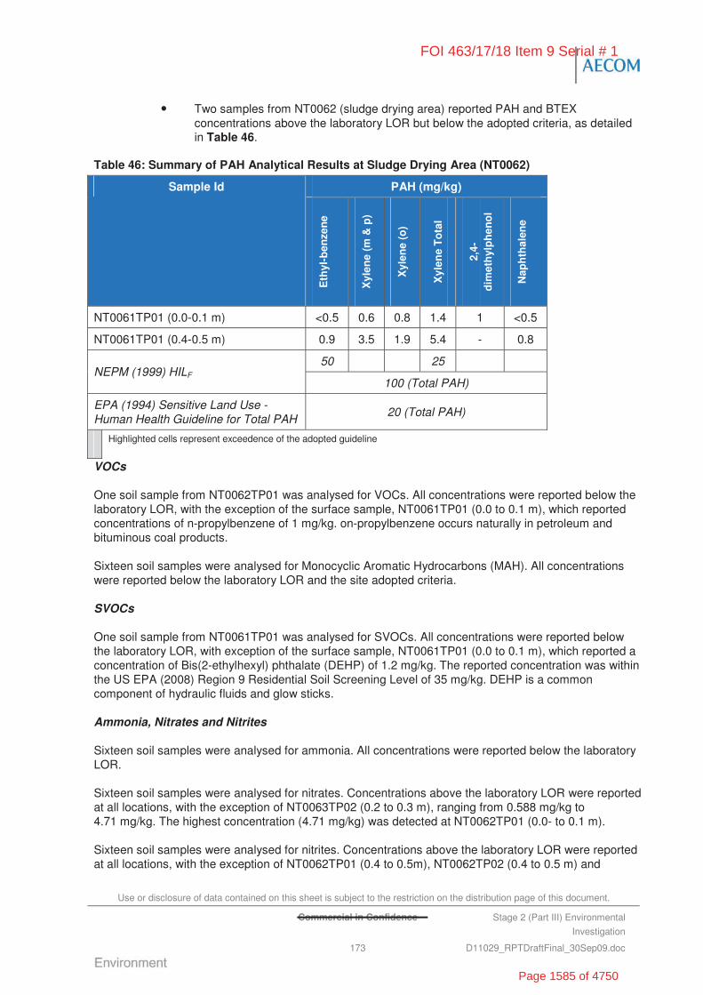
Use or disclosure of data contained on this sheet is subject to the restriction on the distribution page of this document.
Commercial in Confidence Stage 2 (Part III) Environmental
Investigation
173 D11029_RPTDraftFinal_30Sep09.doc
• Two samples from NT0062 (sludge drying area) reported PAH and BTEX concentrations above the laboratory LOR but below the adopted criteria, as detailed in Table 46.
Table 46: Summary of PAH Analytical Results at Sludge Drying Area (NT0062)
PAH (mg/kg) Sample Id
Eth
yl-b
enze
ne
Xyl
ene
(m &
p)
Xyl
ene
(o)
Xyl
ene
To
tal
2,4-
dim
eth
ylp
hen
ol
Nap
hth
alen
e
NT0061TP01 (0.0-0.1 m) <0.5 0.6 0.8 1.4 1 <0.5
NT0061TP01 (0.4-0.5 m) 0.9 3.5 1.9 5.4 - 0.8
50 25 NEPM (1999) HILF
100 (Total PAH)
EPA (1994) Sensitive Land Use - Human Health Guideline for Total PAH
20 (Total PAH)
Highlighted cells represent exceedence of the adopted guideline
VOCs
One soil sample from NT0062TP01 was analysed for VOCs. All concentrations were reported below the laboratory LOR, with the exception of the surface sample, NT0061TP01 (0.0 to 0.1 m), which reported concentrations of n-propylbenzene of 1 mg/kg. on-propylbenzene occurs naturally in petroleum and bituminous coal products.
Sixteen soil samples were analysed for Monocyclic Aromatic Hydrocarbons (MAH). All concentrations were reported below the laboratory LOR and the site adopted criteria.
SVOCs
One soil sample from NT0061TP01 was analysed for SVOCs. All concentrations were reported below the laboratory LOR, with exception of the surface sample, NT0061TP01 (0.0 to 0.1 m), which reported a concentration of Bis(2-ethylhexyl) phthalate (DEHP) of 1.2 mg/kg. The reported concentration was within the US EPA (2008) Region 9 Residential Soil Screening Level of 35 mg/kg. DEHP is a common component of hydraulic fluids and glow sticks.
Ammonia, Nitrates and Nitrites
Sixteen soil samples were analysed for ammonia. All concentrations were reported below the laboratory LOR.
Sixteen soil samples were analysed for nitrates. Concentrations above the laboratory LOR were reported at all locations, with the exception of NT0063TP02 (0.2 to 0.3 m), ranging from 0.588 mg/kg to 4.71 mg/kg. The highest concentration (4.71 mg/kg) was detected at NT0062TP01 (0.0- to 0.1 m).
Sixteen soil samples were analysed for nitrites. Concentrations above the laboratory LOR were reported at all locations, with the exception of NT0062TP01 (0.4 to 0.5m), NT0062TP02 (0.4 to 0.5 m) and
FOI 463/17/18 Item 9 Serial # 1
Page 1585 of 4750

Use or disclosure of data contained on this sheet is subject to the restriction on the distribution page of this document.
Commercial in Confidence Stage 2 (Part III) Environmental
Investigation
174 D11029_RPTDraftFinal_30Sep09.doc
NT0063TP01 (0.2 to 0.3 m), ranging from 0.219 mg/kg to 2.86 mg/kg. The highest concentration (2.86 mg/kg) was detected at NT0063TP02 (0.2 to 0.3 m)
Sixteen soil samples were analysed for Total Oxidised Nitrogen (NOx). All concentrations were reported above the laboratory LOR ranging from 0.472 mg/kg at NT0062TP01 (0.4 to 0.5 m) to 5.57mg/k at NT0063TP03 (0.0 to 0.1 m).
Sixteen soil samples were analysed for Total Nitrogen. All concentrations were reported above the laboratory LOR ranging from 230 mg/kg at NT0062TP01 (0.4 to 0.5m) to 2,020 mg/kg at NT0063TP01 (0.0 to 0.1 m).
Sixteen soil samples were analysed for Total Phosphorus and Reactive Phosphorus. Total phosphorus concentrations were reported at all sample locations ranging from 45 mg/kg at NT0062TP01 (0.4 to 0.5 m) to 368 mg/kg at NT0063TP01 (0.0 to 0.1 m). Reactive Phosphorus concentrations were reported at all sample locations above the laboratory LOR, with the exception of NT0062TP01 (0.4 to 0.5 m), NT0062TP02 (0.4 to 0.5 m) and NT0063TP01 (0.2 to 0.3 m). Concentrations above the laboratory LOR ranged from 0.178 mg/kg at NT0063TP03 (0.2 to 0.3 m) to 14.6 mg/kg at NT0063TP01 (0.0 to 0.1m).
Microbiological
Sixteen soil samples were analysed for total coliforms and faecal coliforms. The four samples collected from NT0062 (sludge drying area) reported concentrations below the laboratory LOR. At NT0063 (horse paddock irrigation area) concentrations were reported above the laboratory LOR, as detailed in Table 47.
Table 47: Microbiological Results from NT0063 Irrigated Horse Paddock
Sample Id Total Coliform (MPN/g)
Faecal Coliforms (MPN/g)
NT0063TP01(0.0 to 0.1 m) 240 <3
NT0063TP01(0.1 to 0.2 m) 93 <3
NT0063TP01(0.2 to 0.3 m) <3 <3
NT0063TP02(0.0 to 0.1 m) <3 <3
NT0063TP02(0.1 to 0.2 m) 93 15
NT0063TP02(0.2 to 0.3 m) <3 <3
NT0063TP03(0.0 to 0.1 m) 240 <3
NT0063TP03(0.1 to 0.2 m) 7 <3
NT0063TP03(0.2 to 0.3 m) <3 <3
NT0063TP04(0.0 to 0.1 m) 2,400 <3
NT0063TP04(0.1 to 0.2 m) 43 23
NT0063TP04(0.2 to 0.3 m) 4 <3
14.5.2 Groundwater Analysis
Groundwater samples were collected down-hydraulic gradient of the Sewage Treatment Facilities from one extraction bore (Bore 20) and two capped bores (Bore 10 and Bore 11) on 11 and 12 November 2008. The groundwater samples were analysed for a range of analytes including physical parameters, metals (NEPM 13), TPH, PAH, MAH, VOC, SVOC, nutrients (ammonia, nitrates, nitrites, total nitrogen, total phosphorus), cations and anions and PFOS/PFOA.
FOI 463/17/18 Item 9 Serial # 1
Page 1586 of 4750
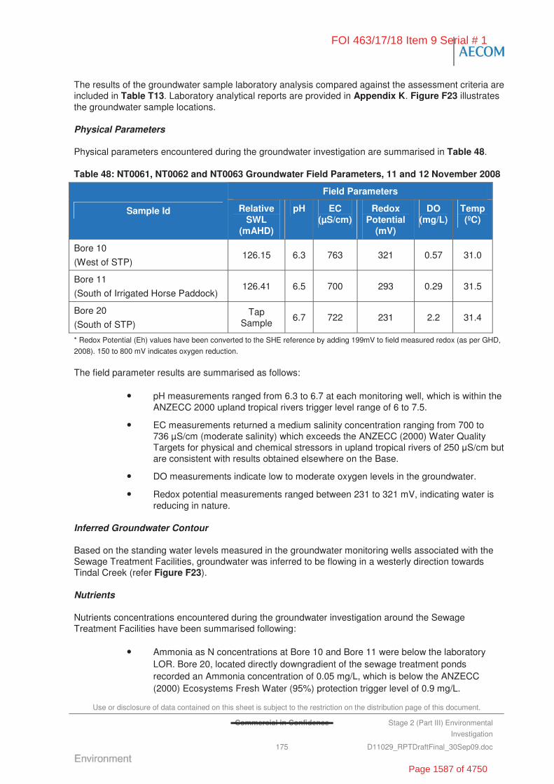
Use or disclosure of data contained on this sheet is subject to the restriction on the distribution page of this document.
Commercial in Confidence Stage 2 (Part III) Environmental
Investigation
175 D11029_RPTDraftFinal_30Sep09.doc
The results of the groundwater sample laboratory analysis compared against the assessment criteria are included in Table T13. Laboratory analytical reports are provided in Appendix K. Figure F23 illustrates the groundwater sample locations.
Physical Parameters
Physical parameters encountered during the groundwater investigation are summarised in Table 48.
Table 48: NT0061, NT0062 and NT0063 Groundwater Field Parameters, 11 and 12 November 2008
Field Parameters
Sample Id Relative SWL
(mAHD)
pH EC (μS/cm)
Redox Potential
(mV)
DO (mg/L)
Temp (ºC)
Bore 10
(West of STP) 126.15 6.3 763 321 0.57 31.0
Bore 11
(South of Irrigated Horse Paddock) 126.41 6.5 700 293 0.29 31.5
Bore 20
(South of STP) Tap
Sample 6.7 722 231 2.2 31.4
* Redox Potential (Eh) values have been converted to the SHE reference by adding 199mV to field measured redox (as per GHD,
2008). 150 to 800 mV indicates oxygen reduction.
The field parameter results are summarised as follows:
• pH measurements ranged from 6.3 to 6.7 at each monitoring well, which is within the ANZECC 2000 upland tropical rivers trigger level range of 6 to 7.5.
• EC measurements returned a medium salinity concentration ranging from 700 to 736 μS/cm (moderate salinity) which exceeds the ANZECC (2000) Water Quality Targets for physical and chemical stressors in upland tropical rivers of 250 S/cm but are consistent with results obtained elsewhere on the Base.
• DO measurements indicate low to moderate oxygen levels in the groundwater.
• Redox potential measurements ranged between 231 to 321 mV, indicating water is reducing in nature.
Inferred Groundwater Contour
Based on the standing water levels measured in the groundwater monitoring wells associated with the Sewage Treatment Facilities, groundwater was inferred to be flowing in a westerly direction towards Tindal Creek (refer Figure F23).
Nutrients
Nutrients concentrations encountered during the groundwater investigation around the Sewage Treatment Facilities have been summarised following:
• Ammonia as N concentrations at Bore 10 and Bore 11 were below the laboratory LOR. Bore 20, located directly downgradient of the sewage treatment ponds recorded an Ammonia concentration of 0.05 mg/L, which is below the ANZECC (2000) Ecosystems Fresh Water (95%) protection trigger level of 0.9 mg/L.
FOI 463/17/18 Item 9 Serial # 1
Page 1587 of 4750

Use or disclosure of data contained on this sheet is subject to the restriction on the distribution page of this document.
Commercial in Confidence Stage 2 (Part III) Environmental
Investigation
176 D11029_RPTDraftFinal_30Sep09.doc
• Nitrate concentrations recorded 0.09 mg/L at Bore 10, 0.04 mg/L at Bore 11 and 0.3 mg/L at Bore 20, all of which are below the ANZECC 95% protection trigger level of 0.7 mg/L.
• Nitrite concentrations were below the laboratory LOR at Bore 10, Bore 11 and Bore 20.
• Total oxidised nitrogen (NOx) concentrations were 0.1 mg/L at Bore 10, 0.04 mg/L at Bore 11 and 0.32 mg/L at Bore 20, which are above the ANZECC (2000) Water Quality Targets for physical and chemical stressors of 0.01 mg/L.
• Total nitrogen concentrations reported were 500 μg/L at Bore 10 and 400 μg/L at Bore 11 and Bore 20. These concentrations exceed the ANZECC (2000) Water Quality Targets for physical and chemical stressors range of 200 to 300 μg/L.
• TKN concentrations recorded for Bore 10 and Bore 11 of 0.4 mg/L and Bore 20 of 0.1 mg/L.
• TP concentrations were within the laboratory LOR of 0.01 mg/L at Bore 10 and Bore 11. Phosphorus concentrations at Bore 20 recorded concentrations of 0.08 mg/L which is above the ANZECC (2000) Water Quality Targets for Physical/Chemical Stressors of 0.01 mg/L.
Major Ions
Major ions were analysed for at Bore 20, down-hydraulic gradient of the sewage treatment ponds. Results have been summarised following. All results were within the ANZECC 2000 stock watering and irrigation water quality guidelines.
• Total anions concentration recorded at Bore 20 were 8.57 meq/L
- total alkalinity as CaCO3 concentrations recorded were 375 mg/L
- chloride concentrations recorded were 34 mg/L
- sulphate as SO42- concentrations recorded were 6 mg/L.
• Total cations concentrations recorded at Bore 20 were 8.41 meq/L
- calcium concentrations recorded were 83 mg/L
- magnesium concentrations recorded were 35 mg/L
- sodium concentrations recorded were 31 mg/L
- potassium concentrations recorded were 1 mg/L.
Metals
The groundwater samples collected from the three bores reported dissolved concentrations of metals less than the ANZECC 95% protection trigger level values for freshwater ecosystems and the NHMRC (2004) Australian Drinking Water – Health guidelines, with the following exceptions:
• Copper – concentration reported at Bore 10 (0.004 mg/L) exceeded the ANZECC 95% protection trigger level of 0.0014 mg/L and was marginally above the background concentration range established for the Base. Bore 11 and 20 where below the laboratory LOR.
• Nickel – concentration reported at Bore 10 (0.025 mg/L) and Bore 11 (0.012 mg/L) exceeded the ANZECC 95% protection trigger level of 0.011 mg/L. Bore 10 also
FOI 463/17/18 Item 9 Serial # 1
Page 1588 of 4750
Use or disclosure of data contained on this sheet is subject to the restriction on the distribution page of this document.
Commercial in Confidence Stage 2 (Part III) Environmental
Investigation
177 D11029_RPTDraftFinal_30Sep09.doc
exceeded the NHMRC health drinking water guideline of 0.02 mg/L. Bore 20 (0.001mg/L) equalled the laboratory LOR.
• Zinc – concentrations reported at Bore 10 (0.015 mg/L) and Bore 20 (0.333 mg/L) exceeded the ANZECC 95% protection trigger level of 0.008 mg/L, but were below the NHMRC health drinking water guideline of 3 mg/L. Bore 11 reported a zinc concentration of 0.005 mg/L.
TPH
The groundwater samples collected from the three bores (Bore 10, Bore 11 and Bore 20) were analysed for TPH. All concentrations were reported below the laboratory LOR.
VOCs
The groundwater samples collected from the three bores (Bore 10, Bore 11 and Bore 20) were analysed for VOCs. All concentrations were reported below the laboratory LOR.
The groundwater samples collected from the three bores (Bore 10, Bore 11 and Bore 20) were analysed for MAH. All concentrations were reported below the laboratory LOR.
SVOCs
The groundwater samples collected from the three bores (Bore 10, Bore 11 and Bore 20) were analysed for SVOCs. All concentrations were reported below the laboratory LOR.
The groundwater samples collected from the three bores (Bore 10, Bore 11 and Bore 20) were analysed for PAH. All concentrations were reported below the laboratory LOR.
PFOS/PFOA
The groundwater samples collected from the three bores (Bore 10, Bore 11 and Bore 20) were analysed for PFOS and PFOA. Concentrations reported for Bore 11 and Bore 20 were below the laboratory LOR. The concentration reported at Bore 10 was 0.1 μg/L, which is less than the adopted assessment criteria (0.3 μg/L).
Microbiological
Bore 20 was analysed for total coliforms and E. coli. Concentrations of total coliforms of 19,863 colony-forming units per 100 millilitre (CFU/100 mL) were reported, exceeding the ANZECC (2000) guideline of 1,000 CFU/100 mL. E. coli concentrations of 16 CFU/100 mL were also detected within Bore 20.
14.5.3 Waste Water Analysis
Samples were collected from the STP on 12 November 2008. Discrete samples were collected from Pond 1, Pond 2 and the system effluent waters. Additionally, a sample was collected of the bottom sediment (sludge) in Pond 1. The samples were analysed for a large suite of chemical and biological constituents, including nutrients, BOD5, Metals, TPH, PAH, MAH, PFOS/PFOA and microbiological, to evaluate the efficacy of the treatment system works.
The results of the waste water laboratory analysis compared against the assessment criteria are included in Error! Reference source not found.. Laboratory analytical reports are provided in Appendix K. Figure F23 illustrates sample locations.
FOI 463/17/18 Item 9 Serial # 1
Page 1589 of 4750
Use or disclosure of data contained on this sheet is subject to the restriction on the distribution page of this document.
Commercial in Confidence Stage 2 (Part III) Environmental
Investigation
178 D11029_RPTDraftFinal_30Sep09.doc
Nutrients
Nutrient concentrations encountered during the waste water investigation at the STP have been summarised following:
• Ammonia as N concentrations were detected in Pond 1 (influent) of 17 mg/L, Pond 2 (in-treatment) of 2.41 mg/L and Effluent Tap of 6.47 mg/L, all of which are above the ANZECC (2000) Ecosystems Fresh Water (95%) protection trigger level of 0.9 mg/L. Ammonia concentrations in the sludge sample were reported below the laboratory LOR.
• Total oxidised nitrogen (NOx) concentrations were 0.1 mg/L at Pond 1, 12.2 mg/L at Pond 2 and 0.12 mg/L at the Effluent Tap, all of which are above the ANZECC (2000) Water Quality Targets for physical and chemical stressors of 0.01 mg/L. NOx concentrations in the sludge sample were below the laboratory LOR.
• Total nitrogen concentrations were 26,100 μg/L at Pond 1, 18,400 μg/L at Pond 2, and 6,400 μg/L at the Effluent Tap, all of which are above the ANZECC (2000) Water Quality Targets for physical and chemical stressors range of 200 to 300 μg/L. Total nitrogen concentrations in the sludge sample recorded 620 mg/kg.
• TKN concentrations were 26 mg/L at Pond 1, 6.2 mg/L at Pond 2 and 6.3 mg/L at the Effluent Tap. The sludge sample returned TKN concentration of 620 mg/kg.
• Total phosphorus concentrations were 5.59 mg/L at Pond 1, 2.7 mg/L at Pond 2 and 1.32 mg/kg at the Effluent Tap, which are above the ANZECC (2000) Water Quality Targets for Physical/Chemical Stressors of 0.01 mg/L.
BOD5
BOD is a broad measure of pollution load in waste waters. It includes any chemical compound that can potentially be stabilized through an oxidation process using oxygen. BOD results from samples within a treatment system can be used as an indicator of the quality of the treatment process, as well as an estimate for the design and sizing of treatment plants and/or processes. BOD5 is the amount of DO consumed in five days by the biological processes breaking down the organic matter.
The waste water sample results obtained on the 15 December 2008 recorded 24 mg/L at Pond 1 and 10 mg/L at Pond 2. The Spotless provided analysis results of samples collected on 8 October 2008 identified BOD5 concentrations of 25 mg/L in Pond 1, 12 mg/L in Pond 2 and 54 mg/L in the Effluent Tap.
BOD as a performance indictor should return results of <20 mg/L based on the NT Government Department of Health and Community Services (1996) Code of Practice for Small On-site Sewage and Sullage Treatment Systems and the Disposal or Reuse of Sewage Effluent.
Metals
The three waste water samples reported dissolved concentrations of metals less than the ANZECC 95% protection trigger level values for freshwater ecosystems, with the following exceptions.
• Copper – concentrations reported at Pond 1 (0.004 mg/L) and the Effluent Tap (0.002 mg/L) exceeded the ANZECC 95% protection trigger level of 0.0014 mg/L. Pond 2 concentration was reported below the laboratory LOR.
• Zinc – concentrations reported at Pond 1 (0.038 mg/L) exceeded the ANZECC 95% protection trigger level of 0.008 mg/L, but were below the NHMRC health drinking
FOI 463/17/18 Item 9 Serial # 1
Page 1590 of 4750
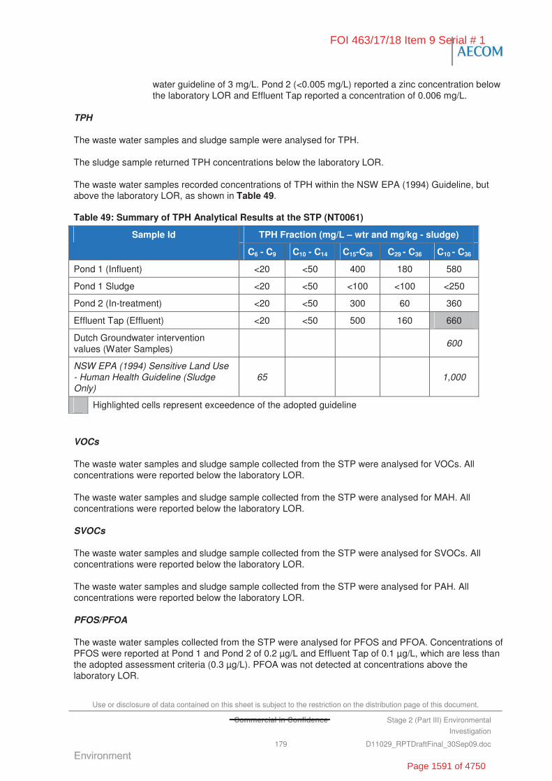
Use or disclosure of data contained on this sheet is subject to the restriction on the distribution page of this document.
Commercial in Confidence Stage 2 (Part III) Environmental
Investigation
179 D11029_RPTDraftFinal_30Sep09.doc
water guideline of 3 mg/L. Pond 2 (<0.005 mg/L) reported a zinc concentration below the laboratory LOR and Effluent Tap reported a concentration of 0.006 mg/L.
TPH
The waste water samples and sludge sample were analysed for TPH.
The sludge sample returned TPH concentrations below the laboratory LOR.
The waste water samples recorded concentrations of TPH within the NSW EPA (1994) Guideline, but above the laboratory LOR, as shown in Table 49.
Table 49: Summary of TPH Analytical Results at the STP (NT0061)
TPH Fraction (mg/L – wtr and mg/kg - sludge) Sample Id
C6 - C9 C10 - C14 C15-C28 C29 - C36 C10 - C36
Pond 1 (Influent) <20 <50 400 180 580
Pond 1 Sludge <20 <50 <100 <100 <250
Pond 2 (In-treatment) <20 <50 300 60 360
Effluent Tap (Effluent) <20 <50 500 160 660
Dutch Groundwater intervention values (Water Samples)
600
NSW EPA (1994) Sensitive Land Use - Human Health Guideline (Sludge Only)
65 1,000
Highlighted cells represent exceedence of the adopted guideline
VOCs
The waste water samples and sludge sample collected from the STP were analysed for VOCs. All concentrations were reported below the laboratory LOR.
The waste water samples and sludge sample collected from the STP were analysed for MAH. All concentrations were reported below the laboratory LOR.
SVOCs
The waste water samples and sludge sample collected from the STP were analysed for SVOCs. All concentrations were reported below the laboratory LOR.
The waste water samples and sludge sample collected from the STP were analysed for PAH. All concentrations were reported below the laboratory LOR.
PFOS/PFOA
The waste water samples collected from the STP were analysed for PFOS and PFOA. Concentrations of PFOS were reported at Pond 1 and Pond 2 of 0.2 μg/L and Effluent Tap of 0.1 μg/L, which are less than the adopted assessment criteria (0.3 μg/L). PFOA was not detected at concentrations above the laboratory LOR.
FOI 463/17/18 Item 9 Serial # 1
Page 1591 of 4750
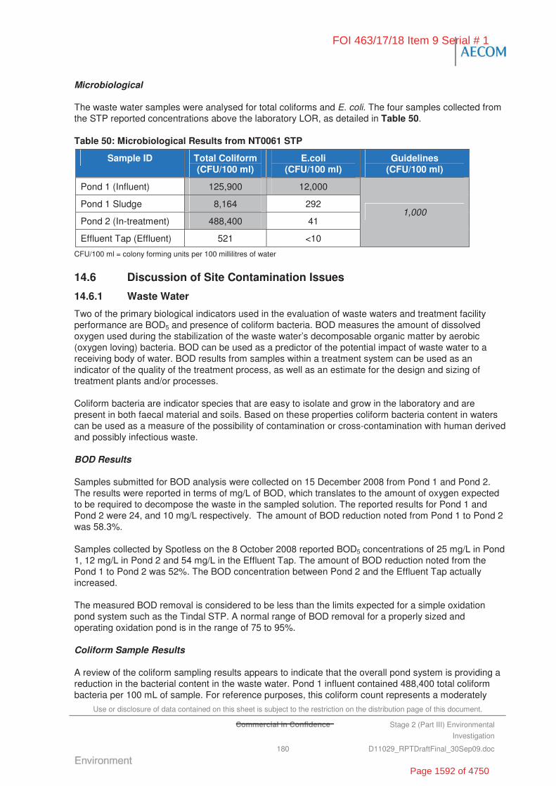
Use or disclosure of data contained on this sheet is subject to the restriction on the distribution page of this document.
Commercial in Confidence Stage 2 (Part III) Environmental
Investigation
180 D11029_RPTDraftFinal_30Sep09.doc
Microbiological
The waste water samples were analysed for total coliforms and E. coli. The four samples collected from the STP reported concentrations above the laboratory LOR, as detailed in Table 50.
Table 50: Microbiological Results from NT0061 STP
Sample ID Total Coliform (CFU/100 ml)
E.coli (CFU/100 ml)
Guidelines (CFU/100 ml)
Pond 1 (Influent) 125,900 12,000
Pond 1 Sludge 8,164 292
Pond 2 (In-treatment) 488,400 41
Effluent Tap (Effluent) 521 <10
1,000
CFU/100 ml = colony forming units per 100 millilitres of water
14.6 Discussion of Site Contamination Issues
14.6.1 Waste Water
Two of the primary biological indicators used in the evaluation of waste waters and treatment facility performance are BOD5 and presence of coliform bacteria. BOD measures the amount of dissolved oxygen used during the stabilization of the waste water’s decomposable organic matter by aerobic (oxygen loving) bacteria. BOD can be used as a predictor of the potential impact of waste water to a receiving body of water. BOD results from samples within a treatment system can be used as an indicator of the quality of the treatment process, as well as an estimate for the design and sizing of treatment plants and/or processes.
Coliform bacteria are indicator species that are easy to isolate and grow in the laboratory and are present in both faecal material and soils. Based on these properties coliform bacteria content in waters can be used as a measure of the possibility of contamination or cross-contamination with human derived and possibly infectious waste.
BOD Results
Samples submitted for BOD analysis were collected on 15 December 2008 from Pond 1 and Pond 2. The results were reported in terms of mg/L of BOD, which translates to the amount of oxygen expected to be required to decompose the waste in the sampled solution. The reported results for Pond 1 and Pond 2 were 24, and 10 mg/L respectively. The amount of BOD reduction noted from Pond 1 to Pond 2 was 58.3%.
Samples collected by Spotless on the 8 October 2008 reported BOD5 concentrations of 25 mg/L in Pond 1, 12 mg/L in Pond 2 and 54 mg/L in the Effluent Tap. The amount of BOD reduction noted from the Pond 1 to Pond 2 was 52%. The BOD concentration between Pond 2 and the Effluent Tap actually increased.
The measured BOD removal is considered to be less than the limits expected for a simple oxidation pond system such as the Tindal STP. A normal range of BOD removal for a properly sized and operating oxidation pond is in the range of 75 to 95%.
Coliform Sample Results
A review of the coliform sampling results appears to indicate that the overall pond system is providing a reduction in the bacterial content in the waste water. Pond 1 influent contained 488,400 total coliform bacteria per 100 mL of sample. For reference purposes, this coliform count represents a moderately
FOI 463/17/18 Item 9 Serial # 1
Page 1592 of 4750

Use or disclosure of data contained on this sheet is subject to the restriction on the distribution page of this document.
Commercial in Confidence Stage 2 (Part III) Environmental
Investigation
181 D11029_RPTDraftFinal_30Sep09.doc
weak waste water as a normal coliform count in municipal waste waters will be on the order of 3 million coliform per 100 mL. The weak waste concentrations could be attributed to the small population served by the system on a daily basis.
The coliform count in Pond 2 was 521 total coliforms per 100 mL sample, which represents a 937 fold reduction in coliform concentration. Based solely on the coliform counts this reduction tends to indicate that the pond system is performing adequately in terms of the reduction of bacteria. Bacteria reduction could be provided in part from biologic activity within the ponds, as well as exposure to sunlight which acts as a natural bactericidal agent due to the ultraviolet light.
The total coliform density measured in the effluent stream was 8,164 total coliforms per 100 mL, which constitutes a 15.7 fold increase from Pond 2 waters. This increase could be attributed to a number of causes the most likely of which is the existence of a bacterial “sink” within the effluent piping. Such a “sink” could come in the form of biofouling or slimes known as bio-films, within the piping. These types of “sinks” can often be reduced/eliminated by cleaning and treatment with a bactericidal agent like super chlorination.
Metals
Samples of waste water collected from Pond 1, Pond 2 and the sewage effluent tap were analysed for mercury, arsenic, barium, beryllium, cadmium, chromium, cobalt, copper, lead, manganese, nickel, vanadium and zinc. Copper, nickel and zinc were reported at concentrations which exceeded the ANZECC (2000) 95% and 90% protection level trigger values for freshwater ecosystems and the NHMRC (2004) Australian Drinking Water – Health Standards. It is noted that the ANZECC trigger values are primarily for protection of surface waters while the NHMRC standards are designed to protect potential recreational or drinking water uses.
It should be noted that the STP provides no direct treatment of heavy metals in the waste waters that enter it. Minor amounts of metals may be removed from the waste water in the process flow through settlement and dissolution leading to deposition into the sludge on the bottom of the ponds. Therefore, consideration of metal contamination will be required for disposal of any sludge material removed from the ponds.
Other Potential Contaminants
Ammonia as N, Total oxidised Nitrogen, Total Nitrogen, and Total Phosphorous were reported at concentrations that exceeded the ANZECC ANZECC (2000) Water Quality Targets for Physical/Chemical Stressors. The Pond 2 and treated effluent tap concentrations were all less than the ANZECC (2000) water quality guidelines for irrigation and stock water. The ANZECC irrigation water quality guidelines are direcly applicable to this application as the treated effluent is disposed of by irrigation and stock watering.
TPH concentrations were reported in Pond 1, Pond 2 and at the effluent tap above the laboratory LOR and, in the case of the effluent tap, above the adopted site assessment criteria. These observations may suggest that hydrocarbon contaminated surface water runoff from the various workshops and maintenance facilities around the Base are finding its way into the sewage system.
PFOS concentrations were also detected in the waste water stream at concentrations above the laboratory LOR, but less than the adopted site assessment criteria for potable water. It is uncertain if these concentrations represent an impact to the waste water stream from Fire Training/Operations on the Base.
FOI 463/17/18 Item 9 Serial # 1
Page 1593 of 4750
Use or disclosure of data contained on this sheet is subject to the restriction on the distribution page of this document.
Commercial in Confidence Stage 2 (Part III) Environmental
Investigation
182 D11029_RPTDraftFinal_30Sep09.doc
14.6.2 Groundwater
In general, the analysis results from the groundwater samples collected from Bore 10, 11 and 20 were less than the adopted site assessment criteria. The only exception was as follows.
• Copper, nickel and zinc were reported at concentrations which exceeded the ANZECC (2000) 95% protection trigger levels. All concentrations were also outside the background concentration ranges established for the Base.
• Electrical conductivity measurements exceeded the ANZECC (2000) Water Quality Targets for physical and chemical stressors in upland tropical rivers but were generally consistent with levels reported for other areas across the Base.
• Total oxidised nitrogen (NOx) (Bore 10 and 20), Total Nitrogen (Bore 10, 11 and 20), and Total Phosphorous (Bore 10 and 11) were reported at concentrations which exceed the ANZECC (2000) Water Quality Targets for physical and chemical stressors.
The PFOS concentration reported in Bore 10 was below the MDH (2007) for potable water but above the laboratory LOR. It is not clear whether the PFOS detection is a result of the activities at the STP or the FTA (NT0064) which is located up-hydraulic gradient of the STP.
Microbiological
A sample from the extraction Bore 20, located south of the STP, reported a total coliform count of 19,863 total coliforms per 100 mL in the groundwater.
The Australian Guidelines for Recreational Water Usage (National Health and Medical Research Council, 1990) recommends that the median faecal coliform density for bathing waters should not exceed 150 faecal coliforms per 100 mL. The faecal coliform density (reported as E. Coli) measured from Bore 20 during the same sample was 16 coliforms per 100 mL, well below the cited limits for bathing waters. In a reference from an on-line review of a document presented by the Queensland Department of Primary Industries and Fisheries, the paper recommends an upper bound limit of coliform densities in drinking water for hogs of 1,000 coliform bacteria per 100 mL.
The total coliform concentration reported for Bore 20 is high for groundwater and may indicate waste water is leaking from the STP. Much of the bacterial contamination observed by this result could be the result of a build-up of bacteria within the well and well pack, overtime, due to pumping. Therefore, an attempt to disinfect the well to improve the quality of the waters pumped from Bore 20, which are used in horse watering (refer to example disinfection procedure in Section 14.7.7, below). As an indicator, the presence of total coliform bacteria at these levels increases the potential for other bacteria and viruses to be present in the well water; although it should be noted that the faecal coliform density (reported as E. coli) was below the guideline for bathing waters recommended by the Australian Guidelines for Recreational Water Usage.
14.6.3 Horse Paddock (NT0063) Soil Sample
Treated water from the STP is pumped, post treatment, from the pond effluent piping to the horse paddock located to the east of the STP. Soil samples were collected from within the paddocks to assess the concentration of contaminants within the soil from the irrigation activities.
Soil analysis results from NT063 were all within the NEPM HILF for industrial/commercial land use and the NEPM EIL, with the exception of vanadium, which was reported at concentrations which are consistent with background levels established for the Base.
FOI 463/17/18 Item 9 Serial # 1
Page 1594 of 4750
Use or disclosure of data contained on this sheet is subject to the restriction on the distribution page of this document.
Stage 2 (Part III) Environmental
Investigation
183 D11029_RPTDraftFinal_30Sep09.doc
Microbiological contamination, in the form of total coliforms was reported at concentrations above the laboratory LOR in all four test pit locations. The highest concentrations were recorded in the surface samples ranging of 240 MPN/g at NT0062TP01 and NT0062TP03 (0.0 to 0.1 m) to 2,400 MPN/g at NT0063TP04 (0.0 to 0.1m). Faecal coliforms were also detected at two sample locations above the laboratory LOR; specifically 15 MPN/g and 23 MPN/g at NT0062TP02 (0.1 to 0.2 m) and NT0063TP04 (0.1 to 0.2 m), respectively.
14.6.4 Sludge Drying Area (NT0062) Soil Samples
Samples were collected from the unlined sludge drying area located south of Pond 1. This area is reportedly used to store sludge from the ponds pending removal from site by waste contractors. It is not clear how often this occurs, given discussions with site personnel suggested that the ponds had not been desludged in the last 10 years.
Olfactory, visual and laboratory analysis confirmed that the current materials in the sludge drying area are not from the sewage treatment ponds.
Soil analysis results from NT0062 were all within the NEPM HILF for industrial/commercial land use and the NEPM EIL, with the exception of:
• Vanadium, which was reported at concentrations which are consistent with background levels established for the Base
• TPH C10-C36 fraction was reported above the NSW EPA (1994) guidelines of 1,000 mg/kg at NT0061TP01 (4,500 mg/kg) during the initial investigations in October 2008 and NT0062-S1 (2,570 mg/kg) and NT0062-S2 (2,550 mg/kg) in April 2009.
• PAH concentrations were also reported above the laboratory LOR for ethyl-benzene, xylene, 2,4 dimethylphenol and Naphthalene.
It appears likely that contaminated soils from accidental leaks and spills. or from the cleaning out of interceptor pit at RAAF Tindal, are being stored at this location because of difficulties associated with arranging contaminated waste materials disposal. Continuing the practice of storing contaminated soils in this unlined pond represents a significant risk to Defence, particularly considering the proximity of the pond to Tindal Creek and the underlying aquifer.
14.7 Summary and Recommendations
14.7.1 Nature and Extent of Soil and Groundwater Contamination
• Chemical Contamination: Chemical contamination was not identified in soil in concentrations that exceeded the NEPM HILF for industrial/commercial land use, with the exception of NT0062 Sludge Drying Area which reported elevated concentrations of TPH C10-C36 exceeding the NSW EPA guideline of 1,000 mg/kg. Chemical contamination was not identified in groundwater in concentrations that exceeded the ANZECC 95% protection trigger values, with the exception of: copper, nickel and zinc and microbiological parameters (total coliforms).
• Chemicals of Concern: The chemicals of concern at the STP (NT0061) and Irrigation Paddocks (NT0063) are related to performance of the system. Chemicals of concern include:
- BOD5
- total coliforms, E. coli and/or Enterrocci spp.
- nitrates
FOI 463/17/18 Item 9 Serial # 1
Page 1595 of 4750
Use or disclosure of data contained on this sheet is subject to the restriction on the distribution page of this document.
Stage 2 (Part III) Environmental
Investigation
184 D11029_RPTDraftFinal_30Sep09.doc
- TPH
- metals, in particular copper, nickel and zinc.
The chemicals of concern for the Sludge Drying Area (NT0062) located behind Pond 1 include:
- TPH, PAH (i.e. naphthalene, 2,4-dimethylphenol, ethyl-benzene and xylenes)
- SVOC (i.e. Bis (2-ethylhexyl) phthalate).
• Soil Investigations:
- The hydrocarbon contaminant concentrations at NT0062 identified in the soil have the potential to impact to human health and environment if practice continues of disposing waste fuels.
- Contaminant concentrations at NT0063 identified in the soil are not expected to pose an adverse impact to human health and are considered to be acceptable for continuing commercial/industrial land use.
• Groundwater Investigation:
- Microbiological contaminant concentrations (specifically total coliforms) identified in groundwater (Bore 20) may pose an adverse impact to human health and are considered to be unacceptable for continuing commercial/industrial land use.
- Copper, nickel and zinc were reported at concentrations which exceeded the ANZECC (2000) 95% protection trigger levels and were also outside the background concentration ranges established for the Base
- PFOS was detected in Bore 10 at a concentration above the laboratory LOR but below the adopted site assessment criteria. It is unclear whether the PFOS detected is the result of the STP or the FTA (NT0064) which is located up-hydraulic gradient of the STP.
14.7.2 NT0061 Sewage Treatment Plant Performance
The STP is underperforming by approximately 20%. The resultant BOD removal is considered to be less than can be reasonably expected for a simple oxidation pond system. A normal range of BOD removal for a properly sized and operating oxidation pond is in the range of 75 to 95%. The BOD reduction currently being achieved by the individual STP ponds is in the order of 55%.
The following summarises the performance findings for the STP:
• The changes in total coliform density between Pond 1 and Pond 2 indicate that the overall pond system is providing an adequate reduction in the bacterial content of the treated waste waters.
• The change in total coliform density from Pond 2 to the the effluent outflow stream (measured at the Effluent Tap) was indicative of there being a bacterial “sink” within the outlet effluent piping.
• Copper, nickel and zinc exceeded the ANZECC (2000) 95% and 90% protection trigger values and the NHMRC (2004) Australian Drinking Water – Health Standards. As such, metal contamination must be considered for the disposal of any sludge material removed from the ponds.
FOI 463/17/18 Item 9 Serial # 1
Page 1596 of 4750

Use or disclosure of data contained on this sheet is subject to the restriction on the distribution page of this document.
Commercial in Confidence Stage 2 (Part III) Environmental
Investigation
185 D11029_RPTDraftFinal_30Sep09.doc
• Ammonia as N, Total oxidised Nitrogen, Total Nitrogen, and Total Phosphorous were reported at concentrations that exceeded the ANZECC (2000) Water Quality Targets for Physical/Chemical Stressors. The Pond 2 and treated effluent tap concentrations were all less than the ANZECC (2000) water quality guidelines for irrigation and stock water.
• TPH concentrations reported in the effluent tap were above the adopted site assessment criteria.
• PFOS concentrations were detected in the waste water stream at concentrations above the laboratory LOR, but less than the adopted site assessment criteria for potable water.
14.7.3 NT0062 Irrigated Horse Paddock
Chemical contamination was not identified in soil in concentrations that exceeded the NEPM HILF for industrial/commercial land use, as follows:
• Vanadium was reported at concentrations exceeding the NEPM EIL but at concentrations that were consistent with background conditions established for the Base.
• Microbiological concentrations in the form of total coliforms were reported at the four test pit locations ranging from 240 MPN/g to 2,400 MPN/g.
14.7.4 NT0063 Sludge Drying Area
Chemical contamination was not identified in soil in concentrations that exceeded the NEPM HILF for industrial/commercial land use, as follows
• Vanadium was reported at concentrations exceeding the NEPM EIL but at concentrations that were consistent with background conditions established for the Base.
• TPH C10-C36 fraction was reported above the NSW EPA (1994) guidelines of 1,000 mg/kg at NT0061TP01 (4,500 mg/kg) during the initial investigations in October 2008 and NT0062-S1 (2,570 mg/kg) and NT0062-S2 (2,550 mg/kg) in April 2009.
The unlined sludge drying area located south of Pond 1 was reportedly used to store the sludge removed from the ponds pending off-site disposal by a waste contractor. The Ponds have reportedly not been desludged in the last 10 years and olfactory, visual and laboratory analysis suggest that the material currently stored in the pond is not from the STP. It is expected that, as a result of continuing waste disposal limitations, the pond is currently being used to store hydrocarbon contaminated sludges and soils resulting from spills or interceptor maintenance.
14.7.5 Risks Identified
Appendix L summarises the assessment of risks associated with the identified contamination at NT0061, NT0062 and NT0063 Sewage Treatment Facilities. The results of the Stage 2 (III) risk assessment are summarised below:
• NT0061 Sewage Treatment Plant and NT0063 Irrigated Horse Paddock – High Risk Band with a Risk Priority score of 153 due to OHS dimension - based on the potential impact to human health from poorly treated irrigation water at the Horse Paddock.
FOI 463/17/18 Item 9 Serial # 1
Page 1597 of 4750
Use or disclosure of data contained on this sheet is subject to the restriction on the distribution page of this document.
Commercial in Confidence Stage 2 (Part III) Environmental
Investigation
186 D11029_RPTDraftFinal_30Sep09.doc
• NT0062 Sludge Drying Area – Medium Risk Band with a Risk Priority score of 154 due to OHS dimension – based on the risk of exposure to contaminated sludge.
14.7.6 Site Specific Recommendations
The following recommendations have been made in relation to NT0061 (STP) Performance, NT0062 (Sludge Drying Pond) and NT0063 (Horse Paddock Irrigation Area):
• Sewage Treatment Plant (NT0061):
- install a larger, automated bar screen (sized to accommodate the maximum anticipated during large military exercises)
- clean or treat the effluent piping between Pond 2 and the effluent outlet to eliminate bacteria “sink” and improve the final water quality of waters leaving the facility (i.e. horse drinking waters)
- desludge the treatment ponds, including off-site disposal of the removed sludges to an appropriate licensed offsite facility
- treat or disinfect Bore 20 using a chlorine solution and adequate contact time within the well; re-treat as necessary; provide well-head chlorination of well water prior to use (refer to the example procedure provided at Section 14.7.7)
- utilise a pesticide with residual capability for application to valve/weir pits (the current procedure to add diesel in the valve/weir pits adds unwanted BOD and toxins to the system)
- upgrade the incinerator (or add dumpster storage for land filling of bar screen wastes) because of the air pollution requirements for using incinerator
- return to the chlorination system to treat effluent; consider renovation or upgrading of the chlorination system to reduce the risk of pathogens in the treated effluent and the risk of the treated effluent impacting on the users of the irrigation / horse paddock
- consider utilisation of a skimmer or vacuum truck for scum/debris removal from STP outlet chambers and pits
- consider the addition of aeration to the treatment ponds for the optimisation of BOD removal; aeration is a simple, cost effective method for improving the performance of the STP
The addition of a floating pond-type aerator to the rear of Pond 1 would increase the efficiency of the entire system, by turning the upper layers of water into an aerobic environment and the water column in Pond 2, into a facultative condition. Both of these respiration methods are as much as three to four times more efficient than anaerobic systems. Based on monitoring of dissolved oxygen (DO) within Pond 1, the operator could turn the aerator on and off to conserve power. Maintaining the pond’s DO level in the range of 1 to 2 mg/L will ensure the most efficient oxidation of BOD without wasting power by over aeration of the waste water.
• As the Base population increases and the capacity of the STP is increased, consider use of packaged unit-treatment processes that can be: (a) added into the treatment train for specific pollutant removal as needed; and (b) added into the treatment train to accommodate peak loadings (for example during military exercises).Sludge Drying Area (NT0062):
- immediately cease disposal of contaminated waste/sludge from the STP and other areas at the Base into the Sludge Drying Area; this area is unlined and
FOI 463/17/18 Item 9 Serial # 1
Page 1598 of 4750
Use or disclosure of data contained on this sheet is subject to the restriction on the distribution page of this document.
Commercial in Confidence Stage 2 (Part III) Environmental
Investigation
187 D11029_RPTDraftFinal_30Sep09.doc
the storage of contamination poses an unacceptable risk to humans and the environment (i.e. Tindal Creek and Katherine Water Control District)
- remove the current accumulation of hydrocarbon contaminated sludge from the sludge drying pond; the extent of excavation should extend to or beyond the depth of the area to ensure all hydrocarbon contamination is removed
- dispose of the excavated hydrocarbon impacted soil to an offsite licensed landfill facility
- regrade the area to remove the current contamination pond and/or reinstate the excavation, following validation, using validated imported fill; validated material may be sourced from either existing borrow pits within the Base, as approved by Defence, or an off-site quarry or borrow pit
- consider construction of a purpose built facility at RAAF Tindal to accommodate on-site management of sewage sludge and other impacted materials (e.g. triple interceptor waste sludge).
• Horse Paddock Irrigation Area (NT0063):
- maintain existing fence around the irrigation area to restrict public and uncontrolled access to the area
- erect signage identifying the general risks associated with the irrigation of effluent
- consider restricting use of the irrigated horse paddock to periods when irrigation is not occurring or conversely restrict irrigation to periods when the horse paddock is not being used
- include area in the CEMP (prepared as part of the Stage 2 (III) Investigations).
14.7.7 Example Procedure for Disinfecting Wells
Wells are most economically disinfected by using a chlorine and water mixture. The safest and most convenient source of chlorine for well disinfection is household laundry bleach. Bleach should not be put into the well straight from the bottle. The general recommendation is to dilute the laundry bleach 1:100, (one litre of bleach to 100 litres of water). Examples of the dilution are provided below:
• A 150 mm diameter well needs 55 L of (chlorine + water) solution for every 6 m of well depth (depth of well below water level). For example, a 60 m deep, 150 mm diameter well, will need 1,100 L of mixture. A new clean garbage can holds about 100 L.
• A 100 mm diameter well needs 26 L of chlorine + water mixture for each 30 m of standing water in the well.
• A 200 mm diameter well needs 96 L of chlorine + water mixture for each 30 m of standing water in the well.
An example procedure for disinfecting a groundwater well is as follows:
• Remove the well cap and pour the chlorine and water solution into the well. Depending on the container used, it will probably be necessary to mix and pour several times to get the right volume of chlorine and water mixture into the well.
• Once all the chlorine mixture is in the well, pour potable water via a hose into the well for at least 15 to 20 minutes. This will ensure that the chlorinated water is circulated.
FOI 463/17/18 Item 9 Serial # 1
Page 1599 of 4750
Use or disclosure of data contained on this sheet is subject to the restriction on the distribution page of this document.
Commercial in Confidence Stage 2 (Part III) Environmental
Investigation
188 D11029_RPTDraftFinal_30Sep09.doc
The hose should also be used to thoroughly rinse down the sides of the well casing above water level.
• In some low yielding wells that are heavily encrusted, the well casing may "fill-up" as the chlorine and water solution is added. In this case, the chlorine and water mixture will need to be added over a longer time.
• The addition of potable water should be continued until there is a smell of chlorine. Leave the chlorinated water in the system, (well and plumbing) for 12 to 24 hours. This will disinfect the whole water system. As an alternative to relying on smell, use a swimming pool chlorine test kit to show whether or not there is chlorine throughout the plumbing system.
• Remove all the chlorinated water from the well by pumping to an appropriate area. Do not put the chlorine solution into a septic system, or a creek (where it could kill fish), or it onto a flower or vegetable garden (where it can kill plants).
• Water removal should continue until all smell of chlorine is gone. Re-sample the well a day or two after the disinfection. Water to be used for direct consumption should never exceed approximately 2 ppm of chlorine (10 ppm can cause severe diarrhoea in mammals.
FOI 463/17/18 Item 9 Serial # 1
Page 1600 of 4750
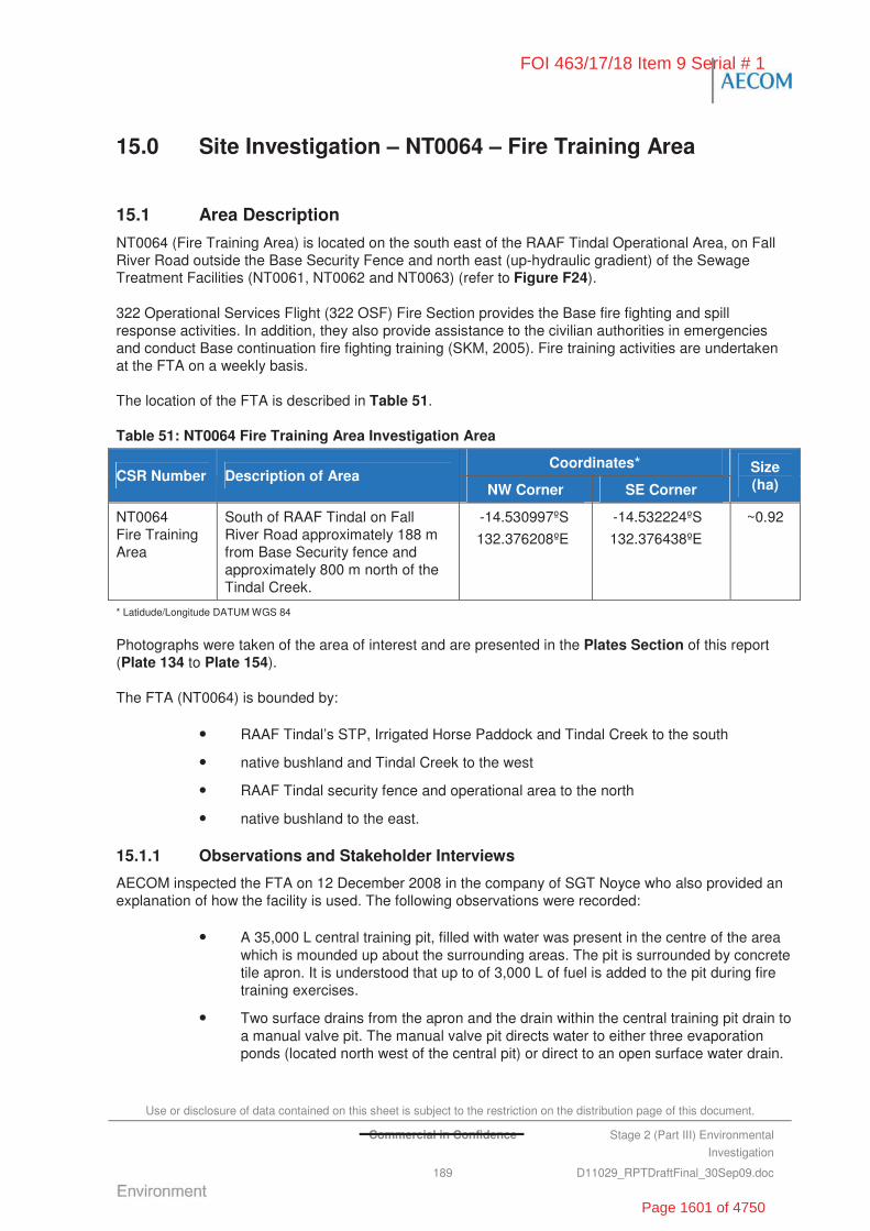
Use or disclosure of data contained on this sheet is subject to the restriction on the distribution page of this document.
Commercial in Confidence Stage 2 (Part III) Environmental
Investigation
189 D11029_RPTDraftFinal_30Sep09.doc
15.0 Site Investigation – NT0064 – Fire Training Area
15.1 Area Description
NT0064 (Fire Training Area) is located on the south east of the RAAF Tindal Operational Area, on Fall River Road outside the Base Security Fence and north east (up-hydraulic gradient) of the Sewage Treatment Facilities (NT0061, NT0062 and NT0063) (refer to Figure F24).
322 Operational Services Flight (322 OSF) Fire Section provides the Base fire fighting and spill response activities. In addition, they also provide assistance to the civilian authorities in emergencies and conduct Base continuation fire fighting training (SKM, 2005). Fire training activities are undertaken at the FTA on a weekly basis.
The location of the FTA is described in Table 51.
Table 51: NT0064 Fire Training Area Investigation Area
Coordinates* CSR Number Description of Area
NW Corner SE Corner
Size (ha)
NT0064 Fire Training Area
South of RAAF Tindal on Fall River Road approximately 188 m from Base Security fence and approximately 800 m north of the Tindal Creek.
-14.530997ºS
132.376208ºE
-14.532224ºS
132.376438ºE
~0.92
* Latidude/Longitude DATUM WGS 84
Photographs were taken of the area of interest and are presented in the Plates Section of this report (Plate 134 to Plate 154).
The FTA (NT0064) is bounded by:
• RAAF Tindal’s STP, Irrigated Horse Paddock and Tindal Creek to the south
• native bushland and Tindal Creek to the west
• RAAF Tindal security fence and operational area to the north
• native bushland to the east.
15.1.1 Observations and Stakeholder Interviews
AECOM inspected the FTA on 12 December 2008 in the company of SGT Noyce who also provided an explanation of how the facility is used. The following observations were recorded:
• A 35,000 L central training pit, filled with water was present in the centre of the area which is mounded up about the surrounding areas. The pit is surrounded by concrete tile apron. It is understood that up to of 3,000 L of fuel is added to the pit during fire training exercises.
• Two surface drains from the apron and the drain within the central training pit drain to a manual valve pit. The manual valve pit directs water to either three evaporation ponds (located north west of the central pit) or direct to an open surface water drain.
FOI 463/17/18 Item 9 Serial # 1
Page 1601 of 4750

Use or disclosure of data contained on this sheet is subject to the restriction on the distribution page of this document.
Commercial in Confidence Stage 2 (Part III) Environmental
Investigation
190 D11029_RPTDraftFinal_30Sep09.doc
• Three elongated concrete lined evaporation ponds are located north west of the central pit. The ponds appear to be connected by a pipe located near the top of the side wall at opposite ends of successive ponds. There is an outlet pipe from the third pond which discharges to an open surface water drain.
• During training exercises involving the central pit:
- the fire truck is parked at the north east end of the pit and foam is sprayed onto the fire set in the pit
- hose pressures during training are maintained at a low 5 bar
- considerable splash of water and foam beyond the concrete apron surrounding the pit occurs (as evidenced by white powder on soil surface).
• The FTA has been reportedly been historically used as a dumping ground for waste disposal from the Base. Multiple timber pallets were observed scattered around the area. Piles of ash and burnt shoes (steel toes and shanks remains), furniture, timber, tyres, tine, rocket shrouds, clothing and timber cable reels were also observed.
• Two 40-foot containers, located south of the central pit, are used for smoke training with the use of breathing apparatus (BA).
• Three 20-foot shipping containers, located south of the central pit, are generally used for ‘Fire Entry’ training, whereby fires, fuelled by timber and fuel (generally using 2 L of AVGAS and/or AVTUR), are set in the container and fire fighters trained in entry procedures.
• Four old vehicles were observed south east of the central pit. The vehicles are reportedly used for access training. The vehicles fuel tanks are removed before use and only water is used to extinguish the fires.
• A 3,500 L waste oil tanker trailer, which is no longer used, was present north west of the central pit. The tanker previously used for collection of hydrocarbons from various sources around the Base for use in fire training exercises. Fire Fighters now use multiple 200 L drums secured on a trailer for training exercises.
• Two unbunded 200 L drums and a manual pump are observed on the ground east of the central pit.
• A mock F-18 (made from 44 gallon drums) was observed adjacent to and south east of the central pit. Fires set on the structure are fuelled by timber with a hydrocarbon propellant.
The FTA is typically used for up to 30 training sessions during major exercise at the Base (e.g. during recent Aces North exercise, when combined training occurred with the US). Otherwise, training typically occurs once per week.
It is understood that the existing FTA will be decommissioned at some stage in the future and be replaced by a new facility designed to accommodate the new fire trucks, known as Panthers, that will be 11.5 m long, 6 wheel drive and weigh 33 tons. A key design consideration for the new FTA will be providing space to manoeuvre the larger and heavier vehicle and providing a more suitable target size.
The new FTA design is the subject of a CSIR (which is applicable to all Bases) and will incorporate:
• a Dry Chemical Powder (DCP) test facility
• a focus testing area
• a 200 m x 200 m concrete pad with a 50 m plane simulator in the middle
FOI 463/17/18 Item 9 Serial # 1
Page 1602 of 4750
Use or disclosure of data contained on this sheet is subject to the restriction on the distribution page of this document.
Commercial in Confidence Stage 2 (Part III) Environmental
Investigation
191 D11029_RPTDraftFinal_30Sep09.doc
• gas fuelled fires controlled from a control room.
During the Stage 2 (III) Investigations, it was reported that the new facility was scheduled for construction by the end of 2011.
15.2 Objectives of the Stage 2 Investigation
To meet the overall objective of the Stage 2 (III) Investigation of defining the ‘true risks’ to Defence of potential contamination, NT0064 (FTA) was investigated to:
• provide additional delineation and characterisation of groundwater contamination identified by previous investigations through completion of a single groundwater monitoring event.
The inclusion of the FTA in the Stage 2 (III) groundwater investigation was to provide further information for development of a Stage 3 Remedial Action Plan for the area of interest.
In addition to the original objectives of the Stage 2 (III) Investigations, a HHERA was commissioned to:
• quantify potential risks to human health and the environment as a result of the fire-fighting chemical contamination present at the Site
• inform Defence regarding specific remediation goals which are considered protective of human health and the environment at the Site.
15.3 Historical Information, Previous Investigations and Potential Chemicals of Concern
15.3.1 Previous Reports
Stage 1 Environmental Investigation
The Stage 1 Environmental Investigation, RAAF Base Tindal, Northern Territory (Stage 1 EI) prepared by ERM (2005) included an assessment of NT0064 (FTA) . As above, the FTA was observed to incorporate a lined fire pit, three evaporation ponds, a cleared area and practice equipment. The Stage 1 EI reported:
• vegetation dieback between the evaporation ponds
• hydrocarbon odours near central pit, burnt shipping containers and leaking diesel tanker
• hydrocarbon soil staining and ash on ground around the central pit
• sludge layer on evaporation pond surface
• AFFF had not been used in training since 2002/2003, but was previously used at the FTA twice a week.
The Stage 1 EI concluded that NT0064 posed a high risk based exposure of humans and the environment to contaminated groundwater contamination.
Stage 2 Environmental Investigation
The Stage 1 and 2 Environmental Investigations NT / K, RAAF Base Tindal (Stage 2 EI) also prepared by ERM (2007a) again assessed the status of NT0064 (FTA). The Stage 2 EI included an assessment of soil and groundwater contamination through test pits and groundwater monitoring wells.
FOI 463/17/18 Item 9 Serial # 1
Page 1603 of 4750

Use or disclosure of data contained on this sheet is subject to the restriction on the distribution page of this document.
Stage 2 (Part III) Environmental
Investigation
192 D11029_RPTDraftFinal_30Sep09.doc
The Stage 2 EI identified that groundwater in the area flows to the west south west toward Tindal Creek and varied in depth according to the season, ranging between 7 mbgl and 15 mbgl. Contamination reported by the Stage 2 EI included:
• PFOS concentrations in soil at 0.5 and 3.0 mbgl
• PFOS concentrations in all sediment samples above the guidelines
• highest PFOS concentration (210 mg/kg) was recorded on the northern side of the fire pit hardstand
• TPH concentrations in one sediment sample (SS05) above guidelines (NSW EPA, 2004)
• TPH concentrations in settlement lagoon outflow above guidelines suggesting no attenuation of TPH concentrations in the settlement ponds and that TPH contaminated waters are released to the environment.
The Stage 2 EI concluded that NT0064 posed a high risk based on the failure of legislative compliance and environment/heritage risks resulting from potential impact on the environment.
The Stage 2 recommendations included:
• development of site specific risk based screening criteria (based on ecological and health exposure)
• remediation pilot trials for ex-situ treatment of PFOS contaminated soils
• groundwater monitoring and installation of additional wells
• secondary containment for the waste oil / fuel tanker and/or upgrade
• installation of an interceptor at the discharge from evaporation ponds
• fencing of the area to control access
• Improvement of occupational health and safety awareness.
Stage 2 (II) Environmental Investigation
The RAAF Tindal, Stage 2 (Part II) Environmental Investigation (Stage 2 (II) EI) prepared by GHD (2008) also assessed the status of NT0064 (FTA). The Stage 2 (II) EI included an assessment of soil and groundwater contamination through test pits and groundwater monitoring wells. The objective of the Stage 2 (II) EI was to delineate soil and groundwater contamination identified by the preceding Stage 2 EI.
The Stage 2 (II) EI confirmed that groundwater in the area around the FTA experiences large fluctuations in depth between the wet and dry seasons. Contamination reported by the Stage 2 (II) EI included:
• 0.5 mm of phase separated hydrocarbons (PSH) in MW01 adjacent to and west of the burn pit
• PFOS and PFOA soil contamination was identified and delineated at investigation locations adjacent to the central pit and in the surface water drainage lines
• PFOS and PFOA soil concentrations:
- generally decreased with depth, but where present at depth, they were typically higher than at the surface
FOI 463/17/18 Item 9 Serial # 1
Page 1604 of 4750

Use or disclosure of data contained on this sheet is subject to the restriction on the distribution page of this document.
Commercial in Confidence Stage 2 (Part III) Environmental
Investigation
193 D11029_RPTDraftFinal_30Sep09.doc
- decreased with distance from the central burn pit
- no soil samples exceeded the PFOS or PFOA MDH guideline for commercial industrial land use (although five samples exceeded the MDH PFOS guideline for residential land use)
• PFOS sediment concentrations (SS1) in the surface water drain south west of the FTA exceeded the MDH commercial industrial guidelines for soil
• PFOS groundwater concentrations were above the adopted MDH guideline of 0.3μg/L at 064MW01, 064MW02, 064MW03 and 064MW05, but were generally less than those reported by the Stage 2 EI. This was attributed to the possible migration of the plume.
The Stage 2 (II) EI (GHD, 2008) concluded that NT0064 posed a high risk based on the known groundwater contamination and the potential for it to impact Tindal Creek.
The recommendation in the Stage 2 (II) Investigation was to continue groundwater, sediment and surface water quality monitoring around the FTA.
15.3.2 Potential Chemicals of Concern
Based on the available historical information, the potential chemicals of concern at NT0064 included:
• PFOS / PFOA associated with the historical use of AFFF
• Hydrocarbons which are used as accelerants for fires set in the FTA.
15.4 Stage 2 (III) Investigation
The Stage 2 (III) Investigation at NT0064 consisted of:
• groundwater sample collection and analysis from three pre-existing groundwater monitoring wells generally located down-hydraulic gradient of the FTA
• undertaking a Human Health and Screening Ecological Risk Assessment (HHERA) of soil and groundwater contamination identified in the vicinity of the FTA.
15.4.1 Groundwater Investigation
The groundwater investigation was undertaken on 11 and 12 November 2008. Three groundwater samples were collected from the pre-existing monitoring wells 064MW02, 064MW03 and 064MW05. The groundwater wells selected for monitoring where chosen because the represented the most significantly impacted groundwater monitoring wells identified by the preceding investigations and also provided a good distribution across and down-hydraulic gradient of the FTA.
The SWL was measured at all monitoring wells located around the FTA (NT0064). Table 52 summarises the monitoring well relative SWL. No PSH were detected in any of the wells tested during November 2008 sampling event.
Table 52: NT0064 Monitoring Well Standing Water Levels
Monitoring Well Location Description Relative SWL (mAHD)
064MW01 ~26 m E of Central Training Pit 134.07
064MW02 ~15 m W of Central Training Pit 129.72
FOI 463/17/18 Item 9 Serial # 1
Page 1605 of 4750
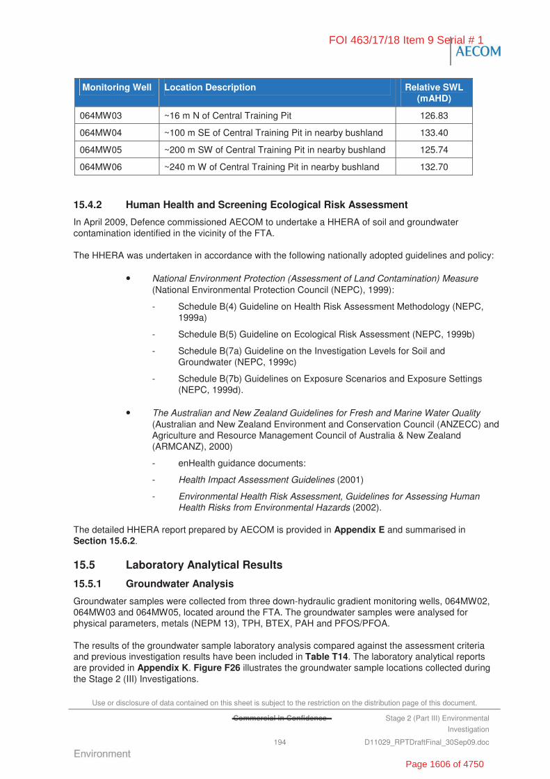
Use or disclosure of data contained on this sheet is subject to the restriction on the distribution page of this document.
Commercial in Confidence Stage 2 (Part III) Environmental
Investigation
194 D11029_RPTDraftFinal_30Sep09.doc
Monitoring Well Location Description Relative SWL (mAHD)
064MW03 ~16 m N of Central Training Pit 126.83
064MW04 ~100 m SE of Central Training Pit in nearby bushland 133.40
064MW05 ~200 m SW of Central Training Pit in nearby bushland 125.74
064MW06 ~240 m W of Central Training Pit in nearby bushland 132.70
15.4.2 Human Health and Screening Ecological Risk Assessment
In April 2009, Defence commissioned AECOM to undertake a HHERA of soil and groundwater contamination identified in the vicinity of the FTA.
The HHERA was undertaken in accordance with the following nationally adopted guidelines and policy:
• National Environment Protection (Assessment of Land Contamination) Measure (National Environmental Protection Council (NEPC), 1999):
- Schedule B(4) Guideline on Health Risk Assessment Methodology (NEPC, 1999a)
- Schedule B(5) Guideline on Ecological Risk Assessment (NEPC, 1999b)
- Schedule B(7a) Guideline on the Investigation Levels for Soil and Groundwater (NEPC, 1999c)
- Schedule B(7b) Guidelines on Exposure Scenarios and Exposure Settings (NEPC, 1999d).
• The Australian and New Zealand Guidelines for Fresh and Marine Water Quality (Australian and New Zealand Environment and Conservation Council (ANZECC) and Agriculture and Resource Management Council of Australia & New Zealand (ARMCANZ), 2000)
- enHealth guidance documents:
- Health Impact Assessment Guidelines (2001)
- Environmental Health Risk Assessment, Guidelines for Assessing Human Health Risks from Environmental Hazards (2002).
The detailed HHERA report prepared by AECOM is provided in Appendix E and summarised in Section 15.6.2.
15.5 Laboratory Analytical Results
15.5.1 Groundwater Analysis
Groundwater samples were collected from three down-hydraulic gradient monitoring wells, 064MW02, 064MW03 and 064MW05, located around the FTA. The groundwater samples were analysed for physical parameters, metals (NEPM 13), TPH, BTEX, PAH and PFOS/PFOA.
The results of the groundwater sample laboratory analysis compared against the assessment criteria and previous investigation results have been included in Table T14. The laboratory analytical reports are provided in Appendix K. Figure F26 illustrates the groundwater sample locations collected during the Stage 2 (III) Investigations.
FOI 463/17/18 Item 9 Serial # 1
Page 1606 of 4750

Use or disclosure of data contained on this sheet is subject to the restriction on the distribution page of this document.
Commercial in Confidence Stage 2 (Part III) Environmental
Investigation
195 D11029_RPTDraftFinal_30Sep09.doc
Physical Parameters
Physical parameters encountered during the groundwater investigation at the FTA have been summarised in Table 53.
Table 53: NT0064 Groundwater Field Parameters, 11 and 12 November 2008
Field Parameters
Sample Id Relative SWL
(mAHD)
pH EC (μS/cm)
Redox Potential
(mV)
DO (mg/L)
Temp (ºC)
064MW02 129.72 7.1 239 378 0.31 31.9
064MW03 126.83 6.7 1,065 354 1.61 32.4
064MW05 125.74 5.8 993 108 0.13 30.5
* Redox Potential (Eh) values have been converted to the SHE reference by adding 199mV to field measured redox (as per GHD,
2008). 150-800 mV indicates oxygen reduction.
The field parameter results are summarised as follows:
• pH measurements ranged from 5.8 to 7.1. 064MW05 exceeded the ANZECC 2000 upland tropical rivers trigger level range of 6 to 7.5.
• EC measurements ranged from 239 to 1,065 μS/cm (indicative of moderate salinity) which exceeds the ANZECC (2000) water quality targets for physical and chemical stressors in upland tropical rivers of 250 S/cm but is consistent with results obtained elsewhere on the Base and during previous investigations at NT0065 (GHD, 2008).
• DO measurements indicated low to moderate oxygen levels in the groundwater.
• Redox potential measurements ranged between 108 to 378 mV, indicating water is aerobic in nature.
Inferred Groundwater Contour
Based on the standing water levels measured in the groundwater monitoring wells associated with NT0064, groundwater was inferred to be flowing in a south west direction towards Tindal Creek (refer to Figure F26).
Metals
The groundwater samples collected from the three wells reported dissolved concentrations of metals generally greater than the ANZECC 95% protection level trigger values for freshwater ecosystems and the NHMRC (2004) Australian Drinking Water – Health guidelines as detailed in Table 54.
Table 54: Dissolved Metal at NT0064, November 2007
Sample Location Analyte
(mg/L) 064MW02 064MW03 064MW05
ANZECC (2000) Ecosystems Fresh Water
(95%)
NHMRC (2004) Australian Drinking
Water - Health
Arsenic 0.01 <0.001 0.005 0.013 0.007
Barium 0.085 0.122 2.28 - 0.7
Cadmium 0.0019 <0.0001 0.0003 0.0002 0.002
FOI 463/17/18 Item 9 Serial # 1
Page 1607 of 4750

Use or disclosure of data contained on this sheet is subject to the restriction on the distribution page of this document.
Commercial in Confidence Stage 2 (Part III) Environmental
Investigation
196 D11029_RPTDraftFinal_30Sep09.doc
Sample Location Analyte
(mg/L) 064MW02 064MW03 064MW05
ANZECC (2000) Ecosystems Fresh Water
(95%)
NHMRC (2004) Australian Drinking
Water - Health
Cobalt <0.001 <0.001 0.014 2.8 -
Copper 0.003 0.001 0.002 0.0014 2
Nickel 0.025 0.036 0.03 0.011 0.02
Vanadium 0.11 <0.01 <0.01 0.006 -
Zinc 0.005 0.007 0.018 0.008 3,000(Aesthetic Value)
Dissolved metal concentrations reported are generally consistent to background concentrations, with the exception of barium, cadmium, nickel, vanadium and zinc, which are generally consistent with previous investigations (ERM, 2007a; GHD, 2008) sampling events.
TPH, BTEX and PAH
The groundwater samples collected from the three wells were analysed for TPH and PAH and BTEX. All concentrations were reported below the laboratory LOR.
PFOS/PFOA
The groundwater samples collected from the three wells were analysed for PFOS/PFOA concentrations.
All samples collected recorded PFOS concentrations above the adopted MDH potable water an USEPA (2009) guideline of 0.3 μg/L and 0.2 μg/L, respectively. A comparison of the PFOS analysis results with those of previous monitoring programs has been provided in Table 55.
Table 55: PFOS Historical Comparison at NT0064 FTA
PFOS Sample Results (μg/L)
Location ERM 2007a May 06
GHD WQMP Jan 07
GHD WQMP Apr 07
GHD 2007
Nov 07
GHD 2008
May 08
AECOM 2008
Nov 08
AECOM 2009
Apr 09
Adopted Guidelines
(μg/L)
064MW02 5,200 - <0.05 85 - 2,700 120
064MW03 3.7 - - 5.3 - 150 -
064MW05 - - - 3.2 - 0.5 -
0.3*/0.2^
Highlighted cells represent exceedances of the adopted guideline
* MDH. 2009. Chronic Exposure Health Risk Limits for PFOS and PFOA in Drinking Water in Health Risk Limits for Groundwater
2008 Rule Revision for Perfluorooctanoic Acid and Perfluorooctane Sulfonate.
^ US EPA. 2009. Provisional Health Advisories for Perfluorooctanoic Acid (PFOA) and Perfluorooctane Sulfonate (PFOS).
PFOA concentrations above the adopted guidelines were also reported at 064MW02 (2.1 μg/L) and 064MW03 (1.3 μg/L). No concentrations were reported at 064MW05.
FOI 463/17/18 Item 9 Serial # 1
Page 1608 of 4750
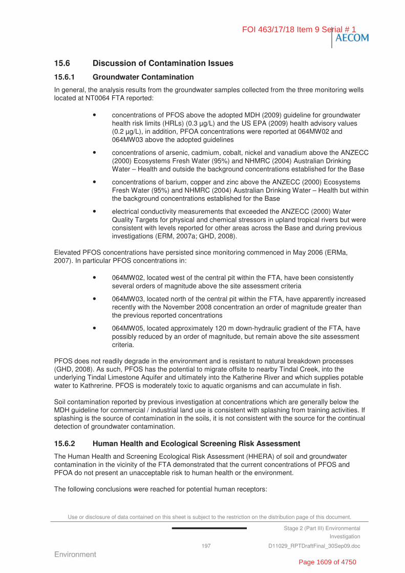
Use or disclosure of data contained on this sheet is subject to the restriction on the distribution page of this document.
Stage 2 (Part III) Environmental
Investigation
197 D11029_RPTDraftFinal_30Sep09.doc
15.6 Discussion of Contamination Issues
15.6.1 Groundwater Contamination
In general, the analysis results from the groundwater samples collected from the three monitoring wells located at NT0064 FTA reported:
• concentrations of PFOS above the adopted MDH (2009) guideline for groundwater health risk limits (HRLs) (0.3 μg/L) and the US EPA (2009) health advisory values (0.2 μg/L), in addition, PFOA concentrations were reported at 064MW02 and 064MW03 above the adopted guidelines
• concentrations of arsenic, cadmium, cobalt, nickel and vanadium above the ANZECC (2000) Ecosystems Fresh Water (95%) and NHMRC (2004) Australian Drinking Water – Health and outside the background concentrations established for the Base
• concentrations of barium, copper and zinc above the ANZECC (2000) Ecosystems Fresh Water (95%) and NHMRC (2004) Australian Drinking Water – Health but within the background concentrations established for the Base
• electrical conductivity measurements that exceeded the ANZECC (2000) Water Quality Targets for physical and chemical stressors in upland tropical rivers but were consistent with levels reported for other areas across the Base and during previous investigations (ERM, 2007a; GHD, 2008).
Elevated PFOS concentrations have persisted since monitoring commenced in May 2006 (ERMa, 2007). In particular PFOS concentrations in:
• 064MW02, located west of the central pit within the FTA, have been consistently several orders of magnitude above the site assessment criteria
• 064MW03, located north of the central pit within the FTA, have apparently increased recently with the November 2008 concentration an order of magnitude greater than the previous reported concentrations
• 064MW05, located approximately 120 m down-hydraulic gradient of the FTA, have possibly reduced by an order of magnitude, but remain above the site assessment criteria.
PFOS does not readily degrade in the environment and is resistant to natural breakdown processes (GHD, 2008). As such, PFOS has the potential to migrate offsite to nearby Tindal Creek, into the underlying Tindal Limestone Aquifer and ultimately into the Katherine River and which supplies potable water to Kathrerine. PFOS is moderately toxic to aquatic organisms and can accumulate in fish.
Soil contamination reported by previous investigation at concentrations which are generally below the MDH guideline for commercial / industrial land use is consistent with splashing from training activities. If splashing is the source of contamination in the soils, it is not consistent with the source for the continual detection of groundwater contamination.
15.6.2 Human Health and Ecological Screening Risk Assessment
The Human Health and Screening Ecological Risk Assessment (HHERA) of soil and groundwater contamination in the vicinity of the FTA demonstrated that the current concentrations of PFOS and PFOA do not present an unacceptable risk to human health or the environment.
The following conclusions were reached for potential human receptors:
FOI 463/17/18 Item 9 Serial # 1
Page 1609 of 4750

Use or disclosure of data contained on this sheet is subject to the restriction on the distribution page of this document.
Stage 2 (Part III) Environmental
Investigation
198 D11029_RPTDraftFinal_30Sep09.doc
• The estimated hazard index for Site staff and trainees under a Reasonable Maximum Exposure (RME) scenario does not exceed a nationally-acceptable risk criterion.
• The estimated risk to maintenance workers undertaking sub-surface soil work for a Reasonable Maximum Exposure (RME) scenario on the Site slightly exceeds the recommended acceptable risk criterion. However the following are relevant to interpreting the risk estimates for that scenario:
- The estimated (30 days per year) duration of subsoil work at the Site used in the risk estimation for future work is considered a conservative exposure duration (i.e. the risk is considered no higher than the estimate and is almost certainly lower).
- The estimates are for RME, not average exposure scenario.
- The modelled concentrations of PFOS and PFOA have been overestimated by using the highest measured level of PFOS /PFOA in surface soil rather than the average concentration which will be encountered.
- PFOS and PFOA contamination in soil are expected to reduce over time because these chemicals are no longer used at the traditional concentrations in current and future AFFF.
Interpretation of the risk estimates for that scenario therefore suggests that the risk to Defence would be considered acceptable.
• The estimated risk for children (assumed age 0 to 6 years old for the risk calculations) and adult residents of the Katherine area and of the Base drinking from the Katherine town water supply does not exceed a nationally acceptable risk criterion.
• The estimated risk for children and adult residents fishing or swimming in the area of Tindal Creek does not exceed a nationally acceptable risk criterion.
• The estimated risk for children of the Katherine area and of the Base, combined activities of drinking from the Katherine town water supply, fishing and swimming in the area of Tindal Creek slightly exceeds a nationally acceptable risk criterion. However the following are relevant to interpreting the risk estimates for that scenario:
- The likelihood that some 5 g of fish derived from the Tindal Creek would be consumed by adults and children over a 64 and 6 year period, respectively, is considered low.
- The Tindal Creek is likely flowing in a manner which might support fish habitation and swimming only in the monsoon season and therefore for a period of only several months of the year.
- PFOS concentrations in Tindal Creek would be expected to be significantly diluted in the creek water compared with groundwater (064MW07) in a scenario where fish habitation is occurring.
- The estimate of PFOS concentration used for the fish bioconcentration calculations is a practical quantitation limit (PQL) lower limit of reporting at 064MW07 and may overestimate the actual concentration of PFOS entering Tindal Creek from groundwater.
Interpretation of the risk estimates for that scenario therefore suggests that the risk to Defence would be considered acceptable.
FOI 463/17/18 Item 9 Serial # 1
Page 1610 of 4750
Use or disclosure of data contained on this sheet is subject to the restriction on the distribution page of this document.
Commercial in Confidence Stage 2 (Part III) Environmental
Investigation
199 D11029_RPTDraftFinal_30Sep09.doc
Overall, the above risk estimates indicate that it is unlikely that an unacceptable risk is posed to Site staff or trainees from routine training activities, and to residents of Tindal Creek, the Base, and Katherine with respect to fish ingestion and recreational activities.
The following conclusions were reached for potential ecological effects:
• The nature of Site activities for fire-training, including foot-traffic, vehicle access, pit-burning, and AFFF use, and given its likely future continuation for this purpose, the terrestrial environment in the immediate vicinity of the Site is highly disturbed, and the terrestrial ecological value of the Site is considered to be low.
• Terrestrial pathways by which wildlife receptors at the Site and adjacent areas may be exposed to soil and surface water contamination nevertheless are considered to be complete. Such pathways would involve PFOS migration from surface soil through wind or rain erosion, depositing PFOS in undergrowth adjacent the Site, and the emergence of groundwater into local creeks.
• In light of the approach used in Australian trigger value guidance for ecological protection, the reported observation that a lowest PFOS concentration NOEC for fish in an early life stage test is only three orders of magnitude above PFOS concentrations reported in a bore water sample taken at the Base (bore RN005771) groundwater entering local watercourses at similar PFOS concentrations potentially represents a risk to the local aquatic food web and to species reproduction. Continued monitoring of groundwater concentrations at 064MW07, 064MW06, and 064MW05, including across seasonal extremes of weather, is advisable in order to ensure that groundwater concentrations do not significantly increase PFOS concentrations in Tindal Creek.
The full findings of the HHERA undertaken by AECOM have been provided in Appendix E.
15.7 Summary and Recommendations
15.7.1 Nature and Extent of Contamination
The findings of the Stage 2 (III) Investigations at NT0064 are as follows:
• Chemical contamination: Chemical contamination, most significantly Perfluoro-octansulfonate (PFOS), was confirmed in groundwater at concentrations which exceed MDH and US EPA guideline health values for groundwater. The PFOS concentrations reported are consistent with those identified by previous investigations (ERM, 2007a; GHD, 2008). Heavy metals concentrations reported in groundwater also exceeded the ANZECC 95% protection trigger values and were consistent with the results reported in previous investigations.
In addition, PFOS contamination in soil has also been reported by previous investigations (ERM, 2007a; GHD, 2008) at concentrations which exceed the MDH guideline for industrial land use.
• Chemicals of Potential Concern:
- PFOS in groundwater and soil
- Heavy metals in groundwater
• Groundwater Investigation:
- Contaminant concentrations identified in groundwater are considered acceptable for human health based on the findings of the HHERA.
FOI 463/17/18 Item 9 Serial # 1
Page 1611 of 4750

Use or disclosure of data contained on this sheet is subject to the restriction on the distribution page of this document.
Stage 2 (Part III) Environmental
Investigation
200 D11029_RPTDraftFinal_30Sep09.doc
- Contaminant concentrations identified in the groundwater require ongoing monitoring in order to ensure that groundwater concentrations do not significantly increase PFOS concentrations in Tindal Creek.
- PFOS contamination has persisted at concentrations exceeding the MDH guideline value for potable water since monitoring commenced in May 2006 (ERM, 2007a). PFOS concentrations within the FTA (064MW02 and 064MW03) have remained several orders of magnitude above the MDH guidelines. PFOS concentrations down-hydraulic gradient of the FTA (064MW05) also remain above the MDH guideline, but are less than previously reported.
- Concentrations of arsenic, cadmium, cobalt, nickel and vanadium were above the ANZECC (2000) Ecosystems Fresh Water (95%) and NHMRC (2004) Australian Drinking Water – Health and outside the background concentrations established for the Base.
- Concentrations of barium, copper and zinc were above the ANZECC (2000) Ecosystems Fresh Water (95%) and NHMRC (2004) Australian Drinking Water – Health but within the background concentrations established for the Base.
- TPH concentrations were not detected at concentrations above the laboratory LOR during the Stage 2 (III) Investigations.
• Human Health and Ecological Risk Assessment
- The HHERA undertaken in relation to the FTA demonstrated that the current concentrations of PFOS and PFOA in soil and groundwater at the FTA do not present an unacceptable risk to human health or the environment.
15.7.2 Risks Identified
Appendix L summarises the assessment of risks associated with the identified contamination at NT0064. The results of the Stage 2 (III) risk assessment are summarised following:
• NT0064 – Medium Risk Band with a Risk Priority score of 143 based on:
- OHS - Potential impacts to human health if exposed to contaminated groundwater noting that the Tindall Limestone Aquifer flows to Katherine River, which is the township’s Potable Water Supply.
- Environment - Potential impacts to ecological receptors, particularly noting Tindal is located within the same catchment area as the Kakadu (Stage I and Stage III) Ramsar Site.
- OHS - Possible detrimental affect on human health (construction workers) exposed to contaminated soils during the planned upgrade of the facility.
15.7.3 Site Specific Recommendations
The following recommendations have been made in relation to NT0064 FTA soil and groundwater contamination:
• PFOS/PFOA Contaminated Soil:
- remove the leaking mobile AST which is understood to no longer used as part of fire training activities and has been observed to be inoperable and leaking
- erect signage and fencing at the FTA to reduce risk for the public to access the area. This is a concern considering the FTA is located outside the Base
FOI 463/17/18 Item 9 Serial # 1
Page 1612 of 4750
Use or disclosure of data contained on this sheet is subject to the restriction on the distribution page of this document.
Commercial in Confidence Stage 2 (Part III) Environmental
Investigation
201 D11029_RPTDraftFinal_30Sep09.doc
security fence and the infrastructure located on site is likely to draw unwanted attention
- manage the identified soil contamination in-situ by including it as part of the site specific CEMP (being developed as part of the Stage 2 (III) Investigations) and pending the redevelopment of the FTA to accommodate the new Fire Fighting Trucks
- include the FTA on the site specific Contamination Environmental Management Plan pending implementation of the recommendations in the RAP.
• PFOS/PFOA Contaminated Groundwater:
- install additional monitoring wells to delineate the extent of the identified PFOS groundwater contamination plume and to provide for early detection of any migration of identified plume toward Tindal Creek
- continue wet and dry season groundwater monitoring in accordance with the Groundwater and Surface Water Monitoring Plan (developed by AECOM as part of the Stage 2 (III) Investigations.
FOI 463/17/18 Item 9 Serial # 1
Page 1613 of 4750

Use or disclosure of data contained on this sheet is subject to the restriction on the distribution page of this document.
Commercial in Confidence Stage 2 (Part III) Environmental
Investigation
202 D11029_RPTDraftFinal_30Sep09.doc
“This page has been left blank intentionally”
FOI 463/17/18 Item 9 Serial # 1
Page 1614 of 4750

Use or disclosure of data contained on this sheet is subject to the restriction on the distribution page of this document.
Stage 2 (Part III) Environmental
Investigation
203 D11029_RPTDraftFinal_30Sep09.doc
16.0 Site Investigation – NT0065 – Fire Station
16.1 Area Description
NT0065 (Fire Station) is located within the Tindal Operational Area, south of the air traffic control tower and west of the SAR and Disposal Area near SAR (NT0049) (Figure F2). The Fire Station is under the control of 322 Operational Services Flight (322 OSF) Fire Section which provides the Base with fire fighting and spill response services. In addition, they also provide assistance to the civilian authorities in emergencies and conduct Base continuation fire fighting training (SKM, 2005).
The location of the area of interest is described in Table 56 and shown in Figure F27.
Photographs were taken of the area of interest and are presented in the Plates Section of this report (Plate 155 to Plate 178).
The Fire Station (NT0065) is bounded by:
• pockets of disturbed bushland and Airfield Lighting to the south
• taxiway and runway and major stormwater drain that drains to Tindal Creek to the west
• Air Traffic Control and 44 Wing Section to the north
• SAR Hangar and pockets of disturbed bushland to the east.
16.1.1 Observations
The Fire Station has been at this location for the past 20 years and consists of the following:
• Fire Station Building (Building 802), which includes an office, laundry, toilets, Fire Vehicle Covered Parking Area, Simulator Room, workshop for general maintenance and a room for Breathing Apparatus (BA) equipment maintenance
• shipping containers located at the eastern end of the fire station building which store miscellaneous equipment including hoses, spare parts, etc. (Plate 155)
• a yellow self bunded Flammable Goods Store, located east of the fire station building. The Flammable Goods Store contains 44 Drip-torches and associated fuel (Plate 156)
• a gravity fed above ground storage tank containing Ansulite 3% AFFF (Formula 1559-26 ICAO-B) located at the south east corner of the Vehicle Covered Parking
FOI 463/17/18 Item 9 Serial # 1
s33
Page 1615 of 4750
Use or disclosure of data contained on this sheet is subject to the restriction on the distribution page of this document.
Commercial in Confidence Stage 2 (Part III) Environmental
Investigation
204 D11029_RPTDraftFinal_30Sep09.doc
Area within the fire station building (Plate 158 to Plate162) (the MSDS for the Ansulite 3% has been provided in Appendix K)
• a concrete and bitumen hardstand area, south of the Vehicle Covered Parking Area which is used for manoeuvring of Fire Trucks entering the fire station building and cleaning and testing of fire lines (Plate 162 to Plate 164).
Surface water runoff from the hardstand area adjacent to the fire station drains to an unlined open storm water drain. The storm water drain conveys surface water runoff from the hardstand to an area approximately 60 m west of the Station which has been variously described as a sink hole/soak/wetland that remains damp all year round. A number of bird species have been noted in the area.
The Fire Station site layout is shown in Figure F28.
16.2 Objectives of the Stage 2 Investigation
To meet the overall objective of the Stage 2 (III) Investigation of defining the ‘true risks’ to Defence of potential contamination, NT0065 (Fire Station) was investigated to:
• confirm whether past and current activities pose a risk of causing soil or groundwater contamination
• measure concentrations of contaminants within soils and sediments
• identify potential human health and ecological receptors.
16.3 Historical Information, Previous Investigations and Potential Chemicals of Concern
16.3.1 Previous Reports
The Stage 1 Environmental Investigation, RAAF Base Tindal, Northern Territory (Stage 1 EI) ERM (2005) included an assessment of the status of NT0065 (Fire Station). The Fire Station was reported to be used for fire truck storage, equipment testing and equipment cleaning. Historically, AFFF has been used and stored at the station. In 2003, AFFF was replaced with a less toxic foam, Ansulite 3%.
The Stage 1 EI (ERM, 2005), reported that the testing of lines and hoses from the fire truck and other fire fighting equipment regularly occurred on the hardstand alongside the Fire Station. It was reported that the foam and waste water was directed into a poorly constructed evaporation pond that was neither lined nor properly maintained.
The Stage 1 EI also referenced a report conducted by URS in June 2002, Fire Station Contamination Investigation. The URS report calculated that an estimated 104,000 L of waste water containing AFFF was disposed into stormwater on an annual basis as a result of the equipment testing activities on the hardstand. Elevated surfactant concentrations were reported in the surface water located behind the Station. The URS report identified the risk as Low, however, no soil or groundwater was tested.
The Stage 1 EI (ERM, 2005) concluded the NT0065 posed a Medium Risk based on potential impacts to groundwater and ecosystems that are supported by the groundwater.
The recommendations in the Stage 1 EI included:
• discontinuing the practice of washing waste water containing residual AFFF into an unlined evaporation pond
• construction of an appropriately lined retention pond to protect the receiving environment.
FOI 463/17/18 Item 9 Serial # 1
Page 1616 of 4750

Use or disclosure of data contained on this sheet is subject to the restriction on the distribution page of this document.
Commercial in Confidence Stage 2 (Part III) Environmental
Investigation
205 D11029_RPTDraftFinal_30Sep09.doc
16.3.2 Potential Chemicals of Concern
Based on the available historical information, the potential chemicals of concern at NT0065 included:
• heavy metals (i.e. arsenic, barium, beryllium, cadmium, chromium, copper, manganese, nickel, lead, mercury, vanadium and zinc)
• hydrocarbons from fire trucks and other equipment
• AFFF as PFOS/PFOA associated with historical use of AFFF.
16.4 Stage 2 (III) Intrusive Investigation
The Stage 2 (III) intrusive investigation at NT0065 initially consisted of:
• additional historical review and interviews with site personnel
• completion of four shallow test pits (hand augured) from adjacent to and down gradient of the hardstand area
• soil sampling and analysis.
In April 2009, additional intrusive investigations were undertaken which included:
• installation of groundwater monitoring well down-hydraulic gradient of NT0065
• completion of eleven test pits to maximum depth of 3 m bgl from the stormwater drain located west of the fire station (foiur locations) and within and adjacent to the wet land (six locations)
• soil and groundwater analysis.
16.4.1 Stakeholder Interviews
An initial site inspection of the fire station was conducted in the company of FLT SGT Bruce Pocklington on 22 October 2008. In addition to the key structures that make up the Fire Station, as described by Section 16.1, the following observations were noted:
• A hardstand area south of the Fire Station is used for the cleaning and testing of fire lines rather than the FTA because there is no dedicated water source at the training area.
• The soils beneath the yellow flammable goods store / container were stained black.
• A number of issues were identified with the Ansulite AST including the tank and the concrete bund was leaking and located only 5 m from a nearby stormwater drain. FLT SGT Pocklington identified that the release tap on the bund had been fixed; however, it was noted to still be leaking during the inspection (Plate 161 and Plate 162).
• Multiple 205 L drums of Ansulite 3% were stored on yellow plastic bunded pallets located behind the AST (Plate 164) together with two 205 L drums of the truck wash Simply Green (Plate 166).
• Trailers, a spill response vehicle and other support equipment were stored outside on the western side of the bitumen hardstand.
• No interceptors were present in the Fire Vehicle Covered Parking Area to stop fuel and oil leaks from entering the nearby stormwater drain. Trucks were noted to be leaking during the site inspection and there is staining on the concrete surface. Drip trays are used beneath the trucks to capture any drips from the vehicles (Plate 167).
FOI 463/17/18 Item 9 Serial # 1
Page 1617 of 4750
Use or disclosure of data contained on this sheet is subject to the restriction on the distribution page of this document.
Commercial in Confidence Stage 2 (Part III) Environmental
Investigation
206 D11029_RPTDraftFinal_30Sep09.doc
• A number of spill kits were available around the Station and appropriate disposal was undertaken by the Base waste contractor.
• Drainage from the wet areas on site (i.e. toilets, sinks, sink in workshop, etc.) drain to the dedicated sewer.
• Surface water runoff from the roof and hardstand areas around station drain via two stormwater drains located south of Building 802 and into the swampy area west of the hardstand (Plate 163 and Plate 168).
A second site inspection and discussion with SGT Noyce was completed on 12 December 2008. The observations made during this interview included:
• 322OSF Fire Section will receive three new fire trucks (known as Panthers) in early 2009. The new Fire Trucks are larger then the existing trucks (specifically 11.5 m long, 6 wheel drive and weight up to 33 tons) and will be capable of holding up to 1,353 L of foam and shooting the water/foam mix up to 90 m in a good wind.
• Ansulite 3% is loaded into the trucks at the fire station via a pump from the AST. The quality of foam concentrate is tested before it is put into the truck using a reflectometer. AFFF can also be removed by draining the truck tanks into drums. AFFF is reused subject to confirmation of quality.
• Historically, fire hoses and pumps containing AFFF were tested on the hardstand area south of the fire station, which drains to the surface water drain and swamp area to the west. It was reported that this is no longer done and that only water is used during tests on the hardstand.
• A bunded 2000 L AFFF storage area, containing 3M AFFF, was located on the eastern side of the hardstand area, along with smaller unbunded containers of Ansulite 3% AFFF.
Figure F28 describes the current fire station infrastructure and layout (including surface water drains).
16.4.2 Soil Investigation
The initial soil investigation was undertaken on 27 October 2008 and comprised the following works:
• Four shallow bore holes (NT0065HA01 to NT0065HA04) hand augured to a maximum depth of 0.5 mbgl. The bore holes were located in the grass area south east of the AFFF AST (NT0065HA03) and within the surface water drain that receives runoff from the hardstand area (NT0065HA01, NT0065HA02 and NT0065HA04).
In addition, supplementary soil investigations were undertaken on 8 and 9 April 2009 and comprised the following works:
• Excavate eleven test pits, to a maximum depth of 3.0 mbgl within the site stormwater drain to confirm initial results returned in October 2008 (NT0065TP01 to NT0065TP04) and within and adjacent to the wet land (NT0065TP05 to NT0065TP11).
• Analyse selected soil samples for PFOA and PFOS, anionic surfactants (by MBAS), TPH, BTEX and a suite of 8 metals (As, Cd, Cr, Cu, Ni, Pb, Zn, Hg).
FOI 463/17/18 Item 9 Serial # 1
Page 1618 of 4750

Use or disclosure of data contained on this sheet is subject to the restriction on the distribution page of this document.
Commercial in Confidence Stage 2 (Part III) Environmental
Investigation
207 D11029_RPTDraftFinal_30Sep09.doc
The soil sampling locations for both investigations have been presented on Figure F29. Logs describing the subsurface soil profile are provided in Appendix H.
Fill Material
No fill material was encountered during the hand augur and test pitting investigations at NT0065.
Natural Soil
During the initial investigations, the stratigraphy encountered comprised of silt with igneous, mudstone and limestone gravels to 0.1 m thickness (NT0065HA03). The stratigraphy encountered at the remaining locations consisted of a thin layer of brown sandy clayey silt at the surface grading to rock. NT0065HA04, located within the surface water drain contained wet clayey silt, with some clay inclusions. The soil sample collected had a green/blue sheen and produced a strong alkaline odour – both of which are characteristic of PFOS contamination.
The rock was red-brown mudstone/siltstone at 0.3 mbgl (NT0065HA01), and hard consolidated silt at 0.1 mbgl (test pits NT0065HA02 and NT0065HA03).
The supplementary soil investigations within the stormwater drain and low lying wet land area comprised of light to dark brown loose to medium dense fine grained sands with some clay in the low lying areas to red/brown silty sand with traces of limestone rounded cobbles in the higher areas.
The surface of the soils in the low lying area west of the Fire Station, where surface water had recently evaporated, appeared to be covered in a fine white, seed shaped matter (refer to Plate 170, Plate 176 and Plate 177). It is suspected that the white matter on the surface is residue of AFFF/Ansulite 3% which is known to be used at the site.
PID screening of soil samples in October 2008 and April 2009 did not suggest the presence of volatiles with PID readings ranging from 0.0 to 2.9 ppm.
16.4.3 Groundwater Investigation
The supplementary investigation at NT0065 required the installation of monitoring wells down hydraulic gradient of the Fire Station and the adjacent near-permanent wet land area (west). The installation of monitoring wells commenced on 8 April 2009. As a result of the underlying geology encountered throughout the area and the high water table, only one out of the five bore holes drilled were successful on the day. Each of the failed boreholes occurred at approximately 3.0 mbgl in the fine grained sands.
During the installation of the monitoring wells at NT0065 (NT0065BH01 to NT0065BH04 and NT0065MW01), groundwater inflow was encountered close to the surface at 4.5 to 5.0 mbgl. The standing water level measured just under a month after installation (30 April 2009) of NT0065MW01 was 2.42 mbgl. In addition, NT0049MW01, located up hydraulic gradient of NT0065 was also sampled to provide background concentrations. The standing water level at NT0049MW01 was 2.55 mbgl.
16.5 Laboratory Analytical Results
16.5.1 Soil Analysis
The soil samples from NT0065 (October 2008) were analysed for a range of CoPC including metals (NEPM 13), TPH, VOC, SVOC and PFOS/PFOA. The supplementary samples collected west of the Fire Station were analysed for a range of CoPC including metals (Suite of 8), TPH/BTEX, Anionic Surfactant as MBAS and PFOS/PFOA.
FOI 463/17/18 Item 9 Serial # 1
Page 1619 of 4750
Use or disclosure of data contained on this sheet is subject to the restriction on the distribution page of this document.
Commercial in Confidence Stage 2 (Part III) Environmental
Investigation
208 D11029_RPTDraftFinal_30Sep09.doc
The results of the soil sample laboratory analysis compared against the assessment criteria are included in Table T16. Laboratory analytical reports are provided in Appendix F. Figure F29 illustrates the sample locations for the initial and supplementary investigations at NT0065 investigation area.
Metals
Eight soil samples were analysed for metals during the initial field investigations (October 2008). All sample concentrations were reported below NEPM HILF and the interim Urban EILs, with the exception of:
• Vanadium (V) concentrations, which were reported in three of the eight samples at concentrations exceeding the EIL criteria of 50 mg/kg. The highest concentration was measured at NT0065HA01 (0.2-0.3m) of 74 mg/kg which is within the background concentration range established for the Base.
Eleven soil samples were analysed for metals during the supplementary investigation (April 2009). All sample concentrations were reported below NEPM HILF and the interim Urban EILs, with the exception of:
• Asenic (As) concentrations, which were reported at only one of the 11 samples at concentrations exceeding the the EIL criteria of 20 mg/kg. The highest concentration was measured at NT0065TP09 (1.2 m) of 28 mg/kg which is within the background concentration range established for the Base.
TPH/BTEX
Eight soil samples were analysed for TPH during the initial investigaiton. All concentrations were reported below the laboratory LOR, with the exception of the one sample from western surface water drain, NT0065TP04 (0-0.1m), which reported TPH C15-C28 and C29-C36 fraction concentrations of 200 mg/kg and 120 mg/kg, respectively. All TPH results were reported at concentrations below the NSW EPA (1994) criteria of 1000 mg/kg. The approximate correlation between TPH fractions and hydrocarbon products is: petrol C6-C9, kerosene C10-C18, diesel C12-C18 and lubricating oils above C18.
Eleven soil samples were analysed for TPH during the supplementary investigation. All concentrations were reported below the laboratory LOR.
VOCs and SVOCs
One soil sample (equating to more than 10% of the samples) was analysed for VOCs and SVOCs during the initial investigations. All concentrations were reported below the laboratory LOR with the exception of the SVOC Bis (2-ethylhexyl) phthalate (DEHP) which was reported at a concentration less than the US EPA (2008) Region 9 Residential Soil Screening Level of 3.5E+01 mg/kg. DEHP is a common component of hydraulic fluids.
PFOS/PFOA
Eight soil samples were analysed for PFOS and PFOA during the initial investigations.
PFOS concentrations above the LOR were reported in all samples ranging from 0.035 mg/kg to 360 mg/kg. Concentrations reported in NT0065HA04 (0.0 to 0.1 m) (190 mg/kg) and NT0065HA04 (0.2 to 0.3 m) (360 mg/kg) both exceeded the MDH (2005) Soil Reference Value (SRV) for PFOS in industrial soils of 40 mg/kg and the more recent SRV (MPCA, 2009) of 14 mg/kg.
PFOA concentrations were reported above the LOR in all samples, except NT0065HA02 (0.0 to 0.3 m), ranging from 0.02 mg/kg to 0.51mg/kg. All concentrations were less than the MDH (2005) Soil
FOI 463/17/18 Item 9 Serial # 1
Page 1620 of 4750

Use or disclosure of data contained on this sheet is subject to the restriction on the distribution page of this document.
Commercial in Confidence Stage 2 (Part III) Environmental
Investigation
209 D11029_RPTDraftFinal_30Sep09.doc
Reference Value for PFOA in industrial soils of 20 mg/kg and the more recent SRV (MPCA, 2009) of 13 mg/kg.
In addition, eleven soil samples were analysed for PFOS and PFOA during the supplementary investigation. The results recorded during April 2009 were lower then the orginal soil investigation; however, exceedances of the MPCA (2009) SRV were recorded at NT0065TP01 (0.5 m), NT0065TP01 (1.2 m) and NT0065TP05 (0.1 m).
Table 57 provides a summary of PFOS/PFOA results for both investigations.
Table 57: NT0065 PFOS/PFOA Results, October 2008 and April 2009
PFOS PFOA PFOS PFOA Sample ID
mg/kg mg/kg Sample ID
mg/kg mg/kg
NT0065HA01(0.0-0.1 m) 4.6 0.023 NT0065TP01 (0.5 m) 52 0.06
NT0065HA01(0.2-0.3 m) 5 0.02 NT0065TP01 (1.2 m) 26 0.05
NT0065HA02(0.0-0.1 m) 0.035 nd NT0065TP02 (0.5 m) 1.4 nd
NT0065HA02(0.2-0.3 m) 0.093 nd NT0065TP03 (0.1 m) 4.1 0.02
NT0065HA03(0.0-0.1 m) 12 0.046 NT0065TP04 (0.1 m) 4.6 0.66
NT0065HA03(0.2-0.3 m) 7.8 0.014 NT0065TP05 (0.1 m) 35 0.52
NT0065HA04(0.0-0.1 m) 190 0.095 NT0065TP06 (0.5 m) 1.9 0.14
NT0065HA04(0.2-0.3 m) 360 0.51 NT0065TP07 (0.5 m) 1.6 0.11
NT0065TP08 (0.1 m) 0.38 nd
NT0065TP09 (1.2 m) 2.4 0.26
NT0065TP10 (0.1 m) 0.04 nd
NT0065TP11 (0.5 m) nd nd
Adopted Assessment Criteria (MPCA, 2009) 14 13
Anionic Surfactant as MBAS
Eleven soil samples were analysed for anionic surfactants as MBAS during the supplementary investigation as a less expensive indicator of whether or not PFOS contamination may be present in soil. Eight of the eleven samples recorded concentrations of MBAS above the laboratory LOR but below the adopted environmental guideline of 100 mg/kg (DoD, 2007).
Table 58 provides a comparison of the MBAS and PFOS/PFOA results recorded in April 2009.
Table 58: NT0065 MBAS Comparison with PFOS/PFOA
PFOS PFOA MBAS Sample ID
mg/kg mg/kg mg/kg
NT0065TP01 (0.5 m) 52 0.06 3.8
NT0065TP01 (1.2 m) 26 0.05 5.1
NT0065TP02 (0.5 m) 1.4 nd <1
FOI 463/17/18 Item 9 Serial # 1
Page 1621 of 4750

Use or disclosure of data contained on this sheet is subject to the restriction on the distribution page of this document.
Commercial in Confidence Stage 2 (Part III) Environmental
Investigation
210 D11029_RPTDraftFinal_30Sep09.doc
PFOS PFOA MBAS Sample ID
mg/kg mg/kg mg/kg
NT0065TP03 (0.1 m) 4.1 0.02 <1
NT0065TP04 (0.1 m) 4.6 0.66 3.1
NT0065TP04 (0.5 m) 3.8
NT0065TP05 (0.1 m) 35 0.52 2.4
NT0065TP06 (0.5 m) 1.9 0.14 2.5
NT0065TP07 (0.1 m) - - 1.3
NT0065TP07 (0.5 m) 1.6 0.11 <1
NT0065TP08 (0.1 m) 0.38 nd <1
NT0065TP09 (1.2 m) 2.4 0.26 <1
NT0065TP10 (0.1 m) 0.04 nd <1
NT0065TP11 (0.5 m) nd nd <!
Adopted Assessment Criteria (MPCA, 2009) 14 13 -
Environmental Guidelines (DoD, 2007) - - 100
16.5.2 Groundwater Analysis
Groundwater samples were collected from the newly installed NT0065MW01 located down-hydraulic gradient and NT0049MW01 located up-hydraulic gradient of the Fire Station and low lying area. The groundwater samples were analysed for physical parameters, PFOA and PFOS, TPH, BTEX and a suite of 8 metals.
The results of the groundwater sample laboratory analysis compared against the assessment criteria have been included in Table T14. The laboratory analytical reports are provided in Appendix K. Figure F29 illustrates the groundwater sample locations collected during the supplementary Stage 2 (III) Investigations.
Physical Parameters
Physical parameters encountered during the groundwater investigation at the FTA have been summarised in Table 53.
Table 59: NT0064 Groundwater Field Parameters, 11 and 12 November 2008
Field Parameters
Sample Id Relative SWL
(mAHD)
pH EC (μS/cm)
Redox Potential
(mV)
DO (mg/L)
Temp (ºC)
NT0065MW01 130.14 7.4 742 337 8.15 31.21
NT0049MW01 130.11 7.2 747 395 7.36 30.31
* Redox Potential (Eh) values have been converted to the SHE reference by adding 199mV to field measured redox (as per GHD,
2008). 150 to 800 mV indicates oxygen reduction.
The field parameter results are summarised as follows:
FOI 463/17/18 Item 9 Serial # 1
Page 1622 of 4750
Use or disclosure of data contained on this sheet is subject to the restriction on the distribution page of this document.
Commercial in Confidence Stage 2 (Part III) Environmental
Investigation
211 D11029_RPTDraftFinal_30Sep09.doc
• pH measurements were neutral recording pH of 7.2 to 7.4 from NT0065MW01 and NT0049MW01 which is within the ANZECC 2000 upland tropical rivers trigger level range of 6 to 7.5.
• EC measurements were also close recording 742 and 747 μS/cm (indicative of moderate salinity), which exceeds the ANZECC (2000) Water Quality Targets for physical and chemical stressors in upland tropical rivers of 250 S/cm but is consistent with results obtained elsewhere on the Base and during previous investigations.
• DO measurements indicate high oxygen levels in the groundwater.
• Redox potential measurements recorded 337 to 395 mV, indicating water is aerobic in nature.
Inferred Groundwater Contour
Based on the standing water levels measured in the groundwater monitoring wells associated with NT0065, groundwater was inferred to be flowing in a westerly direction towards Tindal Creek (refer to Figure F29).
Metals
The groundwater samples collected from the two wells reported dissolved concentrations of metals less than the ANZECC 95% protection level trigger values for freshwater ecosystems and the NHMRC (2004) Australian Drinking Water – Health guidelines, with the following exceptions:
• Copper – concentrations reported at NT0065MW01 (0.005 mg/L) and NT0049MW01 (0.003 mg/L), exceeded the ANZECC 95% protection trigger level of 0.0014 mg/L but were below the NHMRC (2004) Australian Drinking Water – Health of 2 mg/L. All results were within the background concentration ranges established for the Base.
• Zinc – concentrations reported NT0065MW01 (0.047 mg/L) and NT0049MW01 (0.009 mg/L) exceeded the ANZECC 95% protection trigger level of 0.008 mg/L, but were below the NHMRC health drinking water guideline of 3 mg/L. All results were within the background concentration ranges established for the Base.
TPH
The groundwater samples collected from the two wells were analysed for TPH. All concentrations were reported below the laboratory LOR.
BTEX
The groundwater samples collected from the two wells were analysed for BTEX. All concentrations were reported below the laboratory LOR.
PFOS/PFOA
The groundwater samples collected from the two wells were analysed for PFOS/PFOA concentrations. PFOS concentrations were reported as non-detects at NT0064MW01 and NT0049MW01. PFOA concentrations of 0.4 μg/L was reported at NT0064MW01, which was above the adopted MDH (2009) guideline of 0.3 μg/L and US EPA guideline of 0.2 μg/L.
FOI 463/17/18 Item 9 Serial # 1
Page 1623 of 4750

Use or disclosure of data contained on this sheet is subject to the restriction on the distribution page of this document.
Commercial in Confidence Stage 2 (Part III) Environmental
Investigation
212 D11029_RPTDraftFinal_30Sep09.doc
16.6 Discussion of Site Contamination Issues
16.6.1 Soil Contamination
PFOS concentrations reported in the two samples from NT0065TP04 both exceeded the MPCA (2009) Soil Reference Value for PFOS in industrial soils of 14 mg/kg. Additionally, PFOS and PFOA were reported at concentrations exceeding the laboratory LOR in all samples, with the exception of one. In addition PFOS concentrations above the MPCA (2009) SRV of 14 mg/kg were also reported in three of the 11 samples collected as part of the supplementary investigations.
MBAS and PFOA concentrations were also reported above the laboratory LOR but within the adopted site criteria.
Previous investigations at the Fire Station (URS, 2002) reported impact to surface water runoff west of the fire station hardstand area. In particular, elevated concentrations of surfactants (<21 mg/L), hydrocarbons (<1.25 mg/L C10-C35 fraction) and chromium (<0.093 kg/L) were reported. It should be noted that the URS investigation did not include analysis of soil samples for surfactants or AFFF components (i.e. PFOS and PFOA).
TPH and Bis (2-ethylhexyl) phthalate were also detected in concentrations above the laboratory LOR but below the adopted site assessment criteria.
The detection of MBAS, PFOS, PFOA, TPH and Bis(2-ethylhexyl) phthalate suggest that surface water runoff from the hardstand area has impacted the soil/sediment in the surface water drain which conveys water to the nearby wetland/sinkhole/soak located 60 m further west.
16.6.2 Groundwater Contamination
In general, the analysis results from the groundwater samples collected from the two monitoring wells located at and in close proximity to NT0064 Fire Station reported:
• concentrations of PFOA just above the adopted MDH (2009) guideline for groundwater health risk limits (HRLs) of 0.3 μg/L and the USEPA (2009) health advisory values of 0.2 μg/L was reported at NT0065MW01 (0.4 μg/L) located down-hydraulic gradient of the Fire Station. As such, it is suspected groundwater has been impacted from past activities at the Fire Station.
• concentrations of copper and zinc were reported at both NT0064MW01 and NT0049MW01 above the ANZECC (2000) Ecosystems Fresh Water (95%), but below the NHMRC (2004) Australian Drinking Water – Health.
16.7 Summary and Recommendations
16.7.1 Nature and Extent of Contamination
The findings of the Stage 2 (III) Investigations at NT0065 are as follows:
• Chemical contamination: Chemical contamination, most significantly Perfluoro-octansulfonate (PFOS), was confirmed in soil/sediments (and surface water per URS, 2002) in the surface water drain adjacent to the fire station hardstand at concentrations which exceed MPCA (2009) guideline value for commercial / industrial land use. In addition, Perfluorooctanoic acid (PFOA) was confirmed in the down-gradient monitoring well above the MDH and US EPA health guideline values.
• Chemicals of Potential Concern:
- PFOS/PFOA.
FOI 463/17/18 Item 9 Serial # 1
Page 1624 of 4750
Use or disclosure of data contained on this sheet is subject to the restriction on the distribution page of this document.
Commercial in Confidence Stage 2 (Part III) Environmental
Investigation
213 D11029_RPTDraftFinal_30Sep09.doc
• Soil/Sediment Investigation:
- Contaminant concentrations identified in soil / sediment are considered to represent a risk of adverse impact to human health and the environment. Management action is recommended for continuing commercial / industrial land use.
- PFOS concentrations above the LOR were detected in all samples collected at the Fire Station during the initial soil investigations. PFOS concentrations exceeding the MPCA (2009) Soil Reference Value for PFOS in industrial soils of 14 mg/kg were detected within the surface water drain west of the Fire Station hardstand.
- In addition, PFOS concentrations were reported above the laboratory LOR in 12 of the 22 samples collected. Of these, 3 samples recorded concentrations exceeding the MPCA (2009) SRV of 13 mg/kg. This confirms the impact in the surface water drain and soak west of the Fire Station hardstand.
- TPH Fraction C15-C36 and Bis(2-ethylhexyl) phthalate concentrations were also detected in the surface water drain west of the fire station hardstand but at concentrations below the adopted NSW EPA (1994) guideline and the US EPA (2008) Region 9 Residential Soil Screening Level, respectively.
- Surface staining and odours were noted in the soul at base of the Flammable Goods Store.
- Metal concentrations were below the NEPM HILF and NEPM EIL, with the exception of vanadium and arsenic, which was reported at concentrations that are within background concentrations for the Base.
• Groundwater Investigation:
- Contaminant concentrations identified in groundwater are considered to represent a risk of adverse impact to human health and the environment. Management action is recommended for continuing commercial / industrial land use.
- PFOS concentrations were not detected in the up-hydraulic gradient (NT0049MW01) or down-hydraulic gradient (NT0065MW01).
- PFOA concentrations were reported above the adopted MDH (2009) guideline for groundwater health risk limits (HRLs) of 0.3 μg/L and the USEPA (2009) health advisory values of 0.2 μg/L was reported at NT0065MW01 (0.4 μg/L). As such, it is suspected groundwater has been impacted from past activities at the Fire Station.
- Metal concentrations were below the ANZECC 95% protection level trigger values for freshwater ecosystems and the NHMRC (2004) Australian Drinking Water – Health guidelines, with the exceptions of copper and zinc. Concentrations were within the background range established for the Base.
16.7.2 Risks Identified
Appendix L summarises the assessment of risks associated with the identified contamination at NT0065. The results of the Stage 2 (III) risk assessment are summarised following:
• NT0065 – High Risk Band with a Risk Priority score of 153 based on:
- OHS –based on off-site contact with PFOS/PFOA contaminated groundwater
FOI 463/17/18 Item 9 Serial # 1
Page 1625 of 4750
Use or disclosure of data contained on this sheet is subject to the restriction on the distribution page of this document.
Stage 2 (Part III) Environmental
Investigation
214 D11029_RPTDraftFinal_30Sep09.doc
- Environment – based on the potential impact to ecological receptors, particular because Tindal is located within the same catchment area as the Kakadu (Stage I and Stage III) Ramsar Site.
Note that NT0065 Fire Station area has not been subject to the HHERA prepared by AECOM (AECOM, 2009b). Therefore some uncertainty remains as to whether concentrations in soil (higher than that reported at the FTA) and groundwater represent an unacceptable risk.
16.7.3 Site Specific Recommendations
The following recommendations have been made in relation to NT0065 Fire Station soil and groundwater contamination:
• PFOS/PFOA Contaminated Soil:
- fence the area identified impacted soil using a stock fence
- erect signage identifying the general risks associated with the area
- manage the identified soil contamination in-situ by including it as part of the site specific CEMP (developed by AECOM as part of the Stage 2 (III) investigations
- prepare a site specific human health and ecological risk assessment (HHERA) to address the specific risks associated with the Fire Station and adjacent area considering the contaminant concentrations in soil and sediment were greater than those reported at the FTA (NT0064); iIt is anticipated that the FTA HHERA (refer to Appendix E) would be expanded to specifically address the exposure pathways at the Fire Station
- subject to the outcomes of the HHERA, consider remediation of the PFOS/PFOA impacted soil in parallel with redevelopment of the FTA and associated remediation works.
• PFOS/PFOA Contaminated Groundwater:
- continue wet and dry season groundwater monitoring in accordance with the Groundwater and Surface Water Monitoring Plan (developed by AECOM as part of the Stage 2 (III) Investigations).
• General:
- Improve the pollution control measures on site, including:
installation of interceptor trap to treat stormwater runoff prior to entry to the environment
improvement of the integrity (or replace) the AFFF (Ansulite 3%) above ground storage tank and bunding system
improvement of handling practices for AFFF, particularly handling and storage of waste AFFF and decanting of use AFFF from fire trucks
upgrade of the Flammable Goods Store, including installation on a hardstand area at the entrance.
FOI 463/17/18 Item 9 Serial # 1
Page 1626 of 4750

Use or disclosure of data contained on this sheet is subject to the restriction on the distribution page of this document.
Stage 2 (Part III) Environmental
Investigation
215 D11029_RPTDraftFinal_30Sep09.doc
17.0 Site Investigation – NT0072 322 Combat Support Squadron
17.1 Area Description
NT0072 322 CSS is the largest military unit at RAAF Tindal and is responsible for supporting the operations of 75 SQN and other lodger and visiting units. The maintenance activities undertaken by 322 CSS occur at the MEOMS. The MEOMS is located in the north of the Base within close proximity to the administration and medical complex.
The MEOMS has been constructed progressively over the past 15 years and provides engineering and mechanical support through a number of facilities which include:
• NT0053 MEOMS: UST MTOF (Building 333)
• NT0066 MEOMS: Ground Support Equipment (GSE) Maintenance Workshops (Building 345)
• NT0070 MEOMS: Battery Charging Building (Building 340)
• NT0259 MEOMS: Special Purpose Vehicles (SPV) Maintenance Workshops (also known as the Mechanical Equipment Maintenance (MEMs) Workshop) – (Building 344)
• NT0260 MEOMS: Tanker Maintenance Facility (Building 361).
The location of the areas of interest at NT0072 have been described in Table 60 and shown in Figure F30.
FOI 463/17/18 Item 9 Serial # 1
s33
Page 1627 of 4750
Use or disclosure of data contained on this sheet is subject to the restriction on the distribution page of this document.
Commercial in Confidence Stage 2 (Part III) Environmental
Investigation
216 D11029_RPTDraftFinal_30Sep09.doc
The 322 Combat Support Squadron MEOMS (NT072) is bounded by:
• pockets of native bushland to the south
• Base Command Post and the Tindal Golf Course to the west
• medical complex and the Administration and Living Quarters to the north
• native bushland to the east.
17.2 Objectives of the Stage 2 Investigation
To meet the overall objective of the Stage 2 (III) Investigation of defining the ‘true risks’ to Defence of potential contamination, NT0072 322 Combat Support Squadron MEOMS area was investigated to:
• provide additional delineation and characterisation of groundwater contamination identified by previous investigations at NT0053 (MTOF) through completion of an additional groundwater monitoring event
• iIdentify whether identified groundwater contamination (at NT0053 MTOF) poses an adverse health risk to occupiers of buildings, or to users of groundwater in areas surrounding the Site.
The inclusion of the 322 Combat Support Squadron MEOMS in the Stage 2 (III) Investigation was to provide further information for development of a Stage 3 Remedial Action Plan for the area of interest.
17.3 Historical Information, Previous Investigations and Potential Chemicals of Concern
17.3.1 Previous Reports
Stage 1 Environmental Investigation
The Stage 1 Environmental Investigation, RAAF Base Tindal, Northern Territory (Stage 1 EI) prepared by ERM (2005) included an assessment of NT0072 (MEOMS). The MEOMS facility was reported to incorporate a fuel supply facility, Special Purpose Vehicle (SPV) workshop, tanker maintenance workshop, Ground Support Equipment (GSE) workshop, battery store and office buildings. Key observations from the Stage 1 EI included:
• NT0053 (MTOF) incorporated 1 x 41,000 L unleaded petrol (ULP) UST and 1 x 44,000 L Diesel UST. A third ULP UST was reported to have been removed in 1996 after leaking for several years. The MTOF also includes a wash bay which drains to stormwater via a plated interceptor.
• NT0066 (GSE Workshop) exhibited general staining of hardstand areas but was otherwise in good condition.
• NT0259 (SPV Workshop) incorporated a series of pits reportedly draining to an interceptor pit and then stormwater, as well as waste disposal drains which drain to a waste oil tank.
• NT00260 (Tanker Maintenance Workshop) incorporated a sunken pit which drains to an underground interceptor and stormwater and a 1,500 L waste oil sump with significant surface staining suggesting tank overflow.
The Stage 1 EI concluded that NT0072 posed a high risk based on the risk of groundwater contamination.
FOI 463/17/18 Item 9 Serial # 1
Page 1628 of 4750
Use or disclosure of data contained on this sheet is subject to the restriction on the distribution page of this document.
Commercial in Confidence Stage 2 (Part III) Environmental
Investigation
217 D11029_RPTDraftFinal_30Sep09.doc
Stage 2 Environmental Investigation
The Stage 1 and 2 Environmental Investigations NT / K, RAAF Base Tindal (Stage 2 EI) also prepared by ERM 2007a further assessed the status of NT0072 (MEOMS). The Stage 2 EI included an assessment of soil and groundwater contamination through soil bores and groundwater monitoring wells. The findings of the invesitdation are summarized below:
• Limestone bedrock was encountered at depths of between 1.9 and 6.0 mbgl. Groundwater was generally encounted at between 6.0 and 9.0 mbgl and found to flow to the west south west.
• Concentrations of TPH and benzene, toluene, ethylbenzene and xylenes (BTEX) in soil exceeded nominated guidelines in one soil sample at a depth of 3 mbgl located at 053BH02 (TPH Fraction C6-C9 of 250 mg/kg and C10-C16 of 240 mg/kg) where the former ULP UST was removed.
• PSH in the form of LNAPL was identified in two groundwater monitoring wells (053MWA and 053MWB), which are located directly to the south of Building 333, adjacent to Building the MTOF bowsers. LNAPL was reported to be present with thickness up to 100 mm.
• Benzene was reported to be present in groundwater above nominated guideline values in monitoring well 053MW01, located approximately 25 m to the southeast of Building 333.
• TPH impact was reported in the sediment of surface water drains associated with the GSE Workshop (NT0066).
• Some metals, including arsenic, copper, nickel and zinc, were reported to exceed nominated guideline values.
The Stage 2 EI concluded that:
• NT0053 (MTOF) posed a medium risk based on impact to groundwater and sensitive receptors through use for irrigation / domestic abstraction.
• NT0066 (GSE Workshop) posed a medium risk based on impacted sediments observed in stormwater drains.
• NT0070 (Battery Charging) posed a low risk since no contamination was identified.
• NT0259 (SPV Workshop) posed a low risk since no contamination was identified.
• NT0260 (Tanker Maintenance Workshop) posed a low risk since not contamination was identified.
The Stage 2 recommendations included:
• passive PSH recovery (preceded by bail down tests to establish actual PSH thickness) from NT0053
• provision of a triple interceptor at the stormwater discharge point from NT0066 and removal of the identified impacted sediment
• improvement of management protocols for waste oil including tank integrity testing (NT0053, NT00259, NT0260)
• installation of additional groundwater monitoring wells to provide improved spatial coverage and delineation of the identified contamination and conduct routine groundwater monitoring (NT0053).
FOI 463/17/18 Item 9 Serial # 1
Page 1629 of 4750
Use or disclosure of data contained on this sheet is subject to the restriction on the distribution page of this document.
Commercial in Confidence Stage 2 (Part III) Environmental
Investigation
218 D11029_RPTDraftFinal_30Sep09.doc
Stage 2 (II) EI
The RAAF Tindal, Stage 2 (Part II) Environmental Investigation (Stage 2 (II) EI) prepared by GHD (2008) also assessed NT0072 (MEOMS). The Stage 2 (II) EI included further assessment of groundwater contamination at the MTOF (NT0053). The objective of the Stage 2 (II) EI was to delineate groundwater contamination identified by the preceding Stage 2 EI.
According to GHD (2008), Dames and Moore (1999) validation sampling following removal of the leaking historical UST (NT0053) (believed to have been conducted in 1996 or 1997), reported the following:
• concentrations of total petroleum hydrocarbons (TPH) in soils surrounding the USTs marginally exceeded adopted guideline levels
• concentrations of TPH (C10-C14) and benzene in groundwater that exceeded adopted guideline levels.
The Stage 2 (II) EI included an additional groundwater monitoring round and an assessment of groundwater monitoring results conducted within NT0053 in January 2007, April 2007, November 2007 and May 2008. The following conclusions were made:
• Up to 2 m fluctuations in groundwater elevation were observed between the wet and dry seasons with groundwater observed to flow in a south westerly direction.
• Large variations in PSH thickness and contaminant concentrations were observed between monitoring rounds – possibly associated with seasonal water level changes. The maximum PSH thickness reported by GHD (2008) based on gauging conducted on November 2007 was 6 mm (in well 053MWA).
• There appeared to be two hydrocarbon plumes in the area, each with a distinct contamination profile:
- ‘Plume 1’ was characterised by elevated concentrations of shorter chain petroleum hydrocarbons (TPH C6-C9 and BTEX).
- ‘Plume 2’ was characterised by elevated concentrations of longer chain petroleum hydrocarbons (TPH C10-C14, TPH C15-C28 and TPH C29-C36).
• Elevated concentrations of shorter chain hydrocarbons (Plume 1) have been reported in close proximity to locations where LNAPL has been identified, (namely 053MWA and 053MWB in May 2008).
• Highest concentrations of longer chain hydrocarbons (Plume 2) have been reported in monitoring well 053MW05, which is located approximately 60 m south (down gradient) of NT0053.
• GHD (2008) concluded that the longer chain petroleum hydrocarbons that characterise Plume 2 are more likely to have derived from oil/waste oil and possibly diesel fuel (potentially associated with NT0259 or NT0260), while the shorter chain hydrocarbons which characterise Plume 1 are more likely to be derived from unleaded petrol or diesel fuel (NT0053).
The Stage 2 (II) EI concluded that NT0053 posed a high risk based on exposure to humans from vapours via inhalation or contaminated groundwater.
The Stage 2 (II) EI recommendations included:
• development of a site specific Contamination Environmental Management Plan to document management controls
FOI 463/17/18 Item 9 Serial # 1
Page 1630 of 4750
Use or disclosure of data contained on this sheet is subject to the restriction on the distribution page of this document.
Commercial in Confidence Stage 2 (Part III) Environmental
Investigation
219 D11029_RPTDraftFinal_30Sep09.doc
• development of a GSWMP to provide properly document monitoring requirements and trigger levels, as well as prescribing contingency actions in the event that trigger levels are exceeded).
17.3.2 Potential Chemicals of Concern
Based on the available historical information, the potential chemicals of concern at NT0072 in general, and NT0053 in particular, included:
• PAH
• BTEX
• TPH.
17.4 Stage 2 (III) Investigations
The Stage 2 (III) Investigations at the MEOMS (specifically associated with groundwater contamination at NT0053 MTOF) consisted of:
• indoor vapour monitoring in Administration Building 333, adjacent to the MTOF USTs
• preparation of a Human Health Risk Assessment (HHRA) informed by the indoor vapour monitoring
• groundwater sample collection and analysis from three pre-existing groundwater wells in the vicinity of NT0053 MTOF
• a site inspection of the other facilities located within the MEOMS to assist in the development of the Stage 3 Remediation Action Plan.
17.4.1 Air Quality Monitoring
Indoor air monitoring was undertaken within the NT0053 UST MTOF (Building 333) between 2 November 2008 and 7 November 2008.
Monitoring for Volatile Organic Compounds (including Benzene) (VOCs) was undertaken within the workspace of the Building 333. The monitoring was conducted in accordance with AS 2986.1-2003: Workplace air quality - Sampling and analysis of volatile organic compounds by solvent desorption/gas chromatography - Pumped sampling method.
Four static monitoring locations were established within the primary workspace of Building 333. Monitoring was undertaken using a calibrated SKC universal air pump and a series of sorbent tubes to draw in the ambient air over a set period, capturing molecules of gas or vapours on the material within the sorbent tubes. A blank sorbent tube was collected during each monitoring period for quality assurance/quality control purposes.
The tubes were analysed for VOCs by a NATA accredited laboratory with results expressed in milligrams per cubic metre of air sampled (mg/m3). The results were utilised to determine if benzene levels are within the National Exposure Standards for Atmospheric Contaminants in the Occupational Environment [National Occupational Health and Safety Commission (NOSHC):1003 (1995)] recommended exposure level of 16 mg/m3.
Six monitoring events were undertaken over a period of five day, as follows:
• three work days (between Monday and Friday)
• two week nights with the air conditioner off
FOI 463/17/18 Item 9 Serial # 1
Page 1631 of 4750
Use or disclosure of data contained on this sheet is subject to the restriction on the distribution page of this document.
Commercial in Confidence Stage 2 (Part III) Environmental
Investigation
220 D11029_RPTDraftFinal_30Sep09.doc
• one weekend day.
17.4.2 Human Health Risk Assessment
Following the indoor vapour monitoring, a HHRA was undertaken in accordance with the following nationally adopted guidelines and policy:
• National Environment Protection (Assessment of Land Contamination) Measure, Schedule B(4), Health Risk Assessment Methodology (National Environmental Protection Council (NEPC), 1999)
• Environmental Health Risk Assessment, Guidelines for Assessing Human Health Risks from Environmental Hazards (enHealth Council, 2002).
Vapour transport modelling to estimate chemical concentrations in indoor air as a result of volatilisation from groundwater was undertaken using AECOM’s in-house spreadsheets, using methods described in the following documents:
• Standard Guide for Risk-Based Corrective Action Applied at Petroleum Release Sites. E1739 – 95 (American Society for Testing Materials (ASTM) International, reapproved 2002)
• User’s Guide for Evaluating Subsurface Vapor Intrusion into Buildings (US Environmental Protection Agency (US EPA, 2004a).
The ASTM and US EPA guidance documents are based on the fundamental theoretical developments of Johnson and Ettinger (1991), upon which a number guidance documents for derivation of risk-based screening levels at petroleum hydrocarbon impacted Sites are also based (e.g. NZME, 1999). These documents have also been used as reference sources for vapour transport modelling.
The detailed HHRA prepared by AECOM is provided in Appendix D, with a summary presented in Section 17.6.3.
17.4.3 Groundwater Investigation
The groundwater investigation was undertaken on 10 November 2008. Six groundwater samples were collected from the pre-existing monitoring wells: 053MW01, 053MW05, 053MW06, 053MWA, 260MW02 and 070MW01. The groundwater wells selected for monitoring where chosen because the represented the most significantly impacted groundwater monitoring wells identified by the preceding investigations and also provided a good distribution across and down-hydraulic gradient of the MTOF. Bore log construction details are provided in Appendix J.
The SWL was measured at all monitoring wells located around the MEOMS Area (NT0072) during the start up meeting at RAAF Tindal (10 September 2008) and during the groundwater sampling program. Table 61 summarises the monitoring wells SWL. No PSH layer was detected in any of the wells, although an oily sheen was noted in 053MWA.
FOI 463/17/18 Item 9 Serial # 1
Page 1632 of 4750
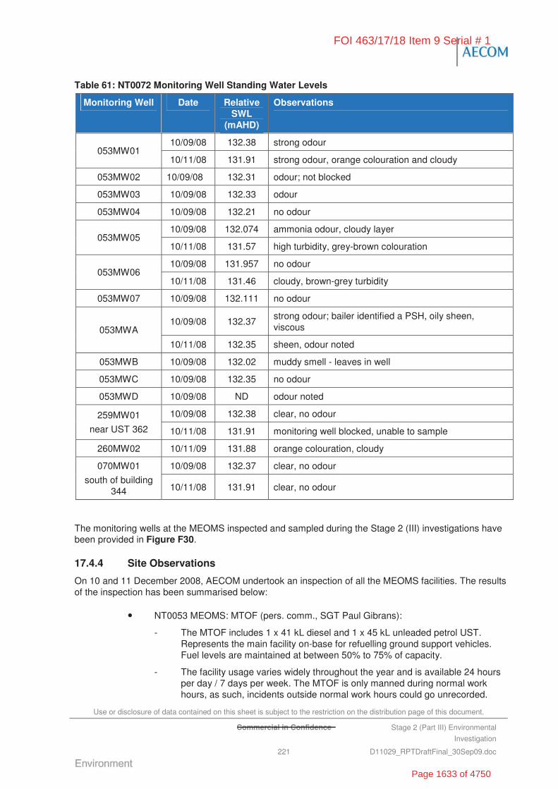
Use or disclosure of data contained on this sheet is subject to the restriction on the distribution page of this document.
Commercial in Confidence Stage 2 (Part III) Environmental
Investigation
221 D11029_RPTDraftFinal_30Sep09.doc
Table 61: NT0072 Monitoring Well Standing Water Levels
Monitoring Well Date Relative SWL
(mAHD)
Observations
10/09/08 132.38 strong odour 053MW01
10/11/08 131.91 strong odour, orange colouration and cloudy
053MW02 10/09/08 132.31 odour; not blocked
053MW03 10/09/08 132.33 odour
053MW04 10/09/08 132.21 no odour
10/09/08 132.074 ammonia odour, cloudy layer 053MW05
10/11/08 131.57 high turbidity, grey-brown colouration
10/09/08 131.957 no odour 053MW06
10/11/08 131.46 cloudy, brown-grey turbidity
053MW07 10/09/08 132.111 no odour
10/09/08 132.37 strong odour; bailer identified a PSH, oily sheen, viscous 053MWA
10/11/08 132.35 sheen, odour noted
053MWB 10/09/08 132.02 muddy smell - leaves in well
053MWC 10/09/08 132.35 no odour
053MWD 10/09/08 ND odour noted
10/09/08 132.38 clear, no odour 259MW01
near UST 362 10/11/08 131.91 monitoring well blocked, unable to sample
260MW02 10/11/09 131.88 orange colouration, cloudy
10/09/08 132.37 clear, no odour 070MW01
south of building 344 10/11/08 131.91 clear, no odour
The monitoring wells at the MEOMS inspected and sampled during the Stage 2 (III) investigations have been provided in Figure F30.
17.4.4 Site Observations
On 10 and 11 December 2008, AECOM undertook an inspection of all the MEOMS facilities. The results of the inspection has been summarised below:
• NT0053 MEOMS: MTOF (pers. comm., SGT Paul Gibrans):
- The MTOF includes 1 x 41 kL diesel and 1 x 45 kL unleaded petrol UST. Represents the main facility on-base for refuelling ground support vehicles. Fuel levels are maintained at between 50% to 75% of capacity.
- The facility usage varies widely throughout the year and is available 24 hours per day / 7 days per week. The MTOF is only manned during normal work hours, as such, incidents outside normal work hours could go unrecorded.
FOI 463/17/18 Item 9 Serial # 1
Page 1633 of 4750
Use or disclosure of data contained on this sheet is subject to the restriction on the distribution page of this document.
Commercial in Confidence Stage 2 (Part III) Environmental
Investigation
222 D11029_RPTDraftFinal_30Sep09.doc
- Heavy staining was observed on the forecourt around bowsers and on the hardstand area behind Building 333.
- Forecourt drains and triple interceptor contained leaves and sediment but are reportedly maintained by Spotless as part of the CMC contract.
- Tank integrity testing records were not available.
• NT0260 MEOMS: Tanker Maintenance Facility (pers. comm., CPRL Hooks)
- Waste Oil from central maintenance pit drains to a 10 kL waste oil tank which also services the SPV Workshop. Visual high level alarm in the Tanker Maintenance Workshop, but not the SPV Workshop. Alarms at 2.7 kL which triggers a manual DEMS request for waste collection. Waste oil tank overflows regularly back into the Tanker Maintenance Workshop central maintenance pit.
- It was reported that there are 22 Tankers located at the Base which require regular maintenance, with an additional 10 during exercises, when peak loading on the facility. Waste tank capacity is inadequate (1 kL of fuel is drained from each truck at each service – therefore capacity to service no more than 10 trucks).
- Drummed waste, bagged fuel filters, used parts and other miscellaneous items were stored outside in an unbunded area pending collection by waste contractor.
- Staining was evident on hardstand areas and within wash bay south of workshop. Drains in the workshop were partially clogged with leaves.
- The triple interceptor is apparently receiving water from the wash bay, which may be results of bypass valve being left open.
- Tank integrity testing records were not available.
• NT0259 MEOMS: SPV Workshop (pers. comm., SGT Sletton):
- The SPV Workshop properly referred to as the Airfield Support Vehicles (AFSV) Workshop, services air field support vehicles including fire trucks, sweepers, forklifts etc.
- Two maintenance pits are present within the workshop. Waste oil is understood to drain to the Waste Oil Tank at the Tanker Maintenance Workshop. If the waste oil tank overflows the Tanker Maintenance Workshop central maintenance pit is filled up.
- The hardstand area to the north of the workshop includes an external hoist that is used for servicing forklifts and is protected by a canopy. A wash bay is also present north of the workshop.
- The number of vehicles serviced at the SPV Workshop depends on the time of the year and Base activities. Reportedly external contractors are used to assist with peak work periods.
- Heavy staining was evident in the hardstand area north of the workshop. There was staining also observed around the external hoist where there are no surface water controls and within the wash bay (which appears to drain to a triple interceptor).
- A number of batteries were observed to be stored outside directly on the ground surface.
FOI 463/17/18 Item 9 Serial # 1
Page 1634 of 4750
Use or disclosure of data contained on this sheet is subject to the restriction on the distribution page of this document.
Commercial in Confidence Stage 2 (Part III) Environmental
Investigation
223 D11029_RPTDraftFinal_30Sep09.doc
• NT0066 MEOMS: GSE Workshop (pers. comm. CPRL Watson and LAC Daniel Dighton):
- The GSE Workshop services ground support equipment including luggage loaders, trolleys, light vehicles, etc. In general, the workshop typically manages only small quantities of oil (approximately 4.5 L per vehicle).
- Waste oils are placed in an above ground tank mounted on a skid/trailer. The waste must be emptied into the tank manually, which results in spillage during windy conditions. The tank is not bunded and is located adjacent to a surface water drain.
- It was reported that it takes up to 12 months to fill the tank at which time the waste is removed by a waste contractor.
- Staining was evident in the concrete lined surface water drains and the area to the north of the workshop was gravel covered.
- Existing interceptor at the end of the concrete surface drain was questionable to whether it’s performing as designed.
- A number of empty drums and containers were observed to be stored inappropriately in unbunded areas/partially on self-bunded pallets (evidence of spillage around the pallets).
• Interceptor Cleanout Cycle (pers. comm., Barry from Spotless):
- The longest period between inspections of the interceptors is 3 months.
- Interceptors are cleaned out as required based on this inspection frequency.
- Interceptors at the workshops are inspected and pumped out more frequently (i.e. monthly).
17.5 Laboratory Analytical Results
17.5.1 Indoor Air Quality Analysis
The results of the indoor air quality sampling have been summarised in the HHRA presented in Appendix D. Laboratory certificates of analysis and field sampling sheets relevant to indoor air sampling are also presented in Appendix D.
The results of the indoor air quality monitoring program have been summarised below.
• Benzene and naphthalene were not reported above laboratory LOR, the majority of sample specific detection limits achieved for these chemicals ranged from 8.6 g/m3 to 74 g/m3 which exceeds the adopted air guideline values of 9.6 g/m3 and 3 g/m3 for benzene and naphthalene, respectively.
• Toluene was reported to be present in indoor air at concentrations up to 52 g/m3. However, this concentration is below the adopted WHO (2000a) air quality guideline value for toluene of 260 g/m3.
• 1,4-dichlorobenzene was reported to be present in indoor air at concentrations exceeding sample-specific detection limits in 22 out of 24 indoor air samples at concentrations ranging from 161 g/m3 to 2,850 g/m3. Reported concentrations in seven out of 24 samples exceeded the adopted air quality guideline value of 1,000 g/m3.
FOI 463/17/18 Item 9 Serial # 1
Page 1635 of 4750

Use or disclosure of data contained on this sheet is subject to the restriction on the distribution page of this document.
Commercial in Confidence Stage 2 (Part III) Environmental
Investigation
224 D11029_RPTDraftFinal_30Sep09.doc
• Other soil and groundwater CoPCs, including ethylbenzene, xylenes, 1,3,5-trimethylbenzene and 1,2,4-trimethylbenzene, were not reported in air at concentrations exceeding adopted air guideline values and/or sample-specific detection limits did not exceed adopted air guideline values. The only exception to this is the detection limit achieved for 1,2,4-trimethylbenzene in one indoor air sample of 74 g/m3, which slightly exceeded the adopted guideline value of 50 g/m3 (WHO, 2000b).
17.5.2 Groundwater Analysis
Groundwater samples were collected from six groundwater monitoring sites located around the NT0053 MTOF facility (053MW01, 053MWB, 053MW05, 053MW06, 260MW02 and 070MW01). The groundwater samples were analysed for physical parameters, metals (NEPM 13), TPH, BTEX, VOCs and SVOCs and MNA parameters.
The results of the groundwater sample laboratory analysis compared against the assessment criteria and previous investigations results are included in Table T17. The laboratory analytical reports are provided in Appendix I. Figure F31 illustrates the groundwater locations sampled as part of the Stage 2 (III) Investigations.
Physical Parameters
Physical parameters encountered during the groundwater investigation at the FTA have been summarised in Table 62.
Table 62: NT0072 Groundwater Field Parameters, 10 November 2008
Field Parameters
Sample Id Relative SWL
(mAHD)
pH EC (μS/cm)
Redox Potential
(mV)
DO (mg/L)
Temp (ºC)
053MW01 131.91 6.6 928 89 0.55 32.4
053MWB 142.84 6.6 998 146 0.35 32.3
053MW05 142.84 6.6 908 36 0.19 33.0
0053MW06 (downgradient)
143.26 6.5 919 42 0.15 32.3
260MW02 144.00 6.5 865 407 1.04 32.6
070MW01 143.29 6.5 1,453 366 0.59 33.4
* Redox Potential (Eh) values have been converted to the SHE reference by adding 199 mV to field measured redox (as per GHD,
2008). 150-800 mV indicates oxygen reduction.
The field parameter results are summarised as follows:
• pH measurements were 6.5 and 6.6 across the site, which is within the ANZECC 2000 upland tropical rivers trigger level range of 6 to 7.5.
• EC measurements ranged from 865 to 1,453 μS/cm (indicative of moderate to high salinity) which exceeds the ANZECC (2000) Water Quality Targets for physical and chemical stressors in upland tropical rivers of 250 S/cm.
• DO measurements indicate low to moderate oxygen levels in the groundwater.
FOI 463/17/18 Item 9 Serial # 1
Page 1636 of 4750
Use or disclosure of data contained on this sheet is subject to the restriction on the distribution page of this document.
Commercial in Confidence Stage 2 (Part III) Environmental
Investigation
225 D11029_RPTDraftFinal_30Sep09.doc
• Redox potential measurements ranged between 36 to 407 mV, indicating water is aerobic in nature and oxygen reduction is occurring in the water body.
Inferred Groundwater Contour
Based on the standing water levels measured in the groundwater monitoring wells associated with NT0072, groundwater was inferred to be flowing in a south west direction towards Tindal Creek (refer to Figure F32).
Metals
The groundwater samples collected from the six monitoring wells reported dissolved concentrations of metals generally less than the ANZECC 95% protection level trigger values for freshwater ecosystems and the NHMRC (2004) Australian Drinking Water – Health guidelines, with the exception of:
• Arsenic – 053MW01 (0.077 mg/L), 053MWB (0.032 mg/L) and 053MW06 (0.023 mg/L) exceeded the ANZECC 95% protection trigger level of 0.013 mg/L and the NHMRC (2004) Australian Drinking Water – Health of 0.007 mg/L. All results were consistent with the background concentrations established for the Base.
• Copper – 053MWB (0.002 mg/L), 260MW02 (0.003 mg/L) and 070MW01 (0.002 mg/L) exceed the ANZECC 95% protection trigger level of 0.0014 mg/L but were below the NHMRC (2004) Australian Drinking Water – Health of 2 mg/L. All results were consistent with the background concentrations established for the Base.
• Nickel – 053MW01 (0.032 mg/L), 260MW02 (0.027 mg/L) and 070MW01 (0.032 mg/L) exceeded the ANZECC 95% protection trigger level of 0.011 mg/L and exceeded the NHMRC health drinking water guideline of 0.02 mg/L. 053MW05 (0.012 mg/L), 053MW06 (0.011 mg/L) exceeded the ANZECC 95% protection trigger level of 0.011 mg/L. All results were above the background concentrations established for the Base.
• Zinc – 053MWB (0.061 mg/L), 260MW02 (0.01 mg/L) and 070MW01 (0.008 mg/L) equalled/exceeded the ANZECC 95% protection trigger level of 0.008 mg/L, but were below the NHMRC health drinking water guideline of 3 mg/L. All results were generally consistent with background concentrations established for the Base.
TPH/BTEX
Groundwater samples collected from the six monitoring wells were analysed for TPH and BTEX. All concentrations were reported below the laboratory LOR at four of the six locations (053MW05, 053MW06, 0260MW02 and 070MW01).
• TPH C6 – C9 fraction concentrations were reported above the laboratory LOR in 053MW01 (4,850 μg/L) and 053MWB (7,230 μg/L), but were lower then results returned during the January 2007 monitoring event (11,100 μg/L) and November 2007 monitoring event (11,483 μg/L), and higher than the May 2006 and April 2007 monitoring of 280 μg/L and 150 μg/L (GHD, 2008).
• TPH C10 – C36 fraction concentrations were reported above the laboratory LOR in 053MW01 (200 μg/L) and 053MWB (1,560 μg/L). 053MWB was the only sample to exceed the Dutch Groundwater Intervention value of 600 g/L.
• BTEX was reported at concentrations above the laboratory LOR in 053MW01 and 053MWB as described in Table 63, below.
FOI 463/17/18 Item 9 Serial # 1
Page 1637 of 4750
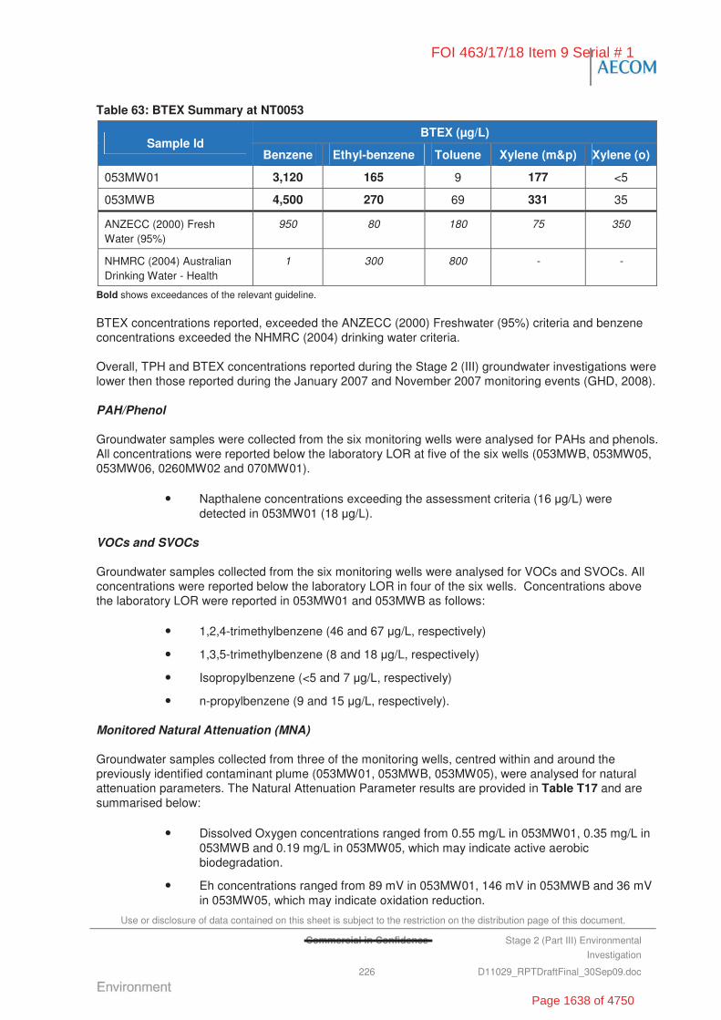
Use or disclosure of data contained on this sheet is subject to the restriction on the distribution page of this document.
Commercial in Confidence Stage 2 (Part III) Environmental
Investigation
226 D11029_RPTDraftFinal_30Sep09.doc
Table 63: BTEX Summary at NT0053
BTEX (μg/L) Sample Id
Benzene Ethyl-benzene Toluene Xylene (m&p) Xylene (o)
053MW01 3,120 165 9 177 <5
053MWB 4,500 270 69 331 35
ANZECC (2000) Fresh Water (95%)
950 80 180 75 350
NHMRC (2004) Australian Drinking Water - Health
1 300 800 - -
Bold shows exceedances of the relevant guideline.
BTEX concentrations reported, exceeded the ANZECC (2000) Freshwater (95%) criteria and benzene concentrations exceeded the NHMRC (2004) drinking water criteria.
Overall, TPH and BTEX concentrations reported during the Stage 2 (III) groundwater investigations were lower then those reported during the January 2007 and November 2007 monitoring events (GHD, 2008).
PAH/Phenol
Groundwater samples were collected from the six monitoring wells were analysed for PAHs and phenols. All concentrations were reported below the laboratory LOR at five of the six wells (053MWB, 053MW05, 053MW06, 0260MW02 and 070MW01).
• Napthalene concentrations exceeding the assessment criteria (16 g/L) were detected in 053MW01 (18 g/L).
VOCs and SVOCs
Groundwater samples collected from the six monitoring wells were analysed for VOCs and SVOCs. All concentrations were reported below the laboratory LOR in four of the six wells. Concentrations above the laboratory LOR were reported in 053MW01 and 053MWB as follows:
• 1,2,4-trimethylbenzene (46 and 67 g/L, respectively)
• 1,3,5-trimethylbenzene (8 and 18 g/L, respectively)
• Isopropylbenzene (<5 and 7 g/L, respectively)
• n-propylbenzene (9 and 15 g/L, respectively).
Monitored Natural Attenuation (MNA)
Groundwater samples collected from three of the monitoring wells, centred within and around the previously identified contaminant plume (053MW01, 053MWB, 053MW05), were analysed for natural attenuation parameters. The Natural Attenuation Parameter results are provided in Table T17 and are summarised below:
• Dissolved Oxygen concentrations ranged from 0.55 mg/L in 053MW01, 0.35 mg/L in 053MWB and 0.19 mg/L in 053MW05, which may indicate active aerobic biodegradation.
• Eh concentrations ranged from 89 mV in 053MW01, 146 mV in 053MWB and 36 mV in 053MW05, which may indicate oxidation reduction.
FOI 463/17/18 Item 9 Serial # 1
Page 1638 of 4750
Use or disclosure of data contained on this sheet is subject to the restriction on the distribution page of this document.
Stage 2 (Part III) Environmental
Investigation
227 D11029_RPTDraftFinal_30Sep09.doc
• Chloride concentrations ranged from 62 mg/L in 053MW01, 78 mg/L in 053MWB and 100 mg/L in 053MW05.
• Sulfate as SO42- concentrations were within the laboratory LOR of <1.0 mg/L, which
indicates low concentrations, as such, sulfate reduction is expected to be minimal
• Nitrate as N concentrations reported were within 0.01 mg/L at 053MW01, 053MWB and 053MW05, which may indicate nitrate reduction is occurring.
• Calcium concentrations ranged from 97 mg/L in 053MW01, 96 mg/L in 053MWB and 114 mg/L in 053MW05.
• Magnesium concentrations of magnesium ranged from 44 mg/L in 053MW01, 50 mg/L in 053MWB and 46 mg/L in 053MW05.
• Sodium concentrations ranged from 30 mg/L in 053MW01, 33 mg/L in 053MWB and 10 mg/L in 053MW05.
• Potassium concentrations ranged from ranged from 2 mg/L in 053MW01, 2 mg/L in 053MWB and 1 mg/L in 053MW05.
• Ferrous iron concentrations ranged from 3.96 mg/L in 053MW01, 0.69 mg/L in 053MWB and 1.17 mg/L in 053MW05, which may indicate that iron reduction occurring in a limited capacity.
• Ammonia concentrations ranged from 0.14 mg/L in 053MW01, <0.01 mg/L in 053MWB and 0.04 mg/L in 053MW05.
• Methane concentrations ranged from 0.335 mg/L in 053MW01, 1.38 mg/L in 053MWB and 1.7 mg/L in 053MW05, which doesn’t indicate microbial degradation of hydrocarbons through methanogenesis.
• Total Organic Carbon (TOC) results ranged from 30 mg/L in 053MW01, 47 mg/L in 053MWB and 22 mg/L in 053MW05, which indicate elevated concentrations showing that the groundwater is a suitable environment for bacterial activity.
• Increased alkalinity in monitoring wells also indicates the occurrence of microbial activity and available buffering capacity.
In summary, the analysis of natural attenuation parameters provides evidence of an established environment where natural attenuation processes are occurring. It should be noted that ferrous iron and nitrate analysis were conducted outside of holding times due to the remote location of the site and as such should be used as an indicative measure of biodegradation only.
The high levels of recharge during the wet season provide significant influx of oxygenated groundwater which should aid in the biodegradation of the existing hydrocarbon contamination.
17.6 Discussion of Site Contamination Issues
17.6.1 Indoor Air Quality
Reported concentrations of toluene within Building 333 (measured at various times between 2 November and 7 November 2008) ranged from 0.009 mg/m3 to 0.074 mg/m3 (arithmetic mean of detected concentrations was 0.022 mg/m3). The reported mean and maximum concentrations were below the NOHSC occupation exposure standard (TWA; 377 mg/m3) and below the WHO (2000) ambient air quality guideline value of 0.260 mg/m3.
Reported concentrations of 1,4-dichlorobenzene (1,4-DCB) within Building 333 ranged from < 0.01 mg/m3 to 2.85 mg/m3. The reported maximum concentration was below the National Occupational Health and Safety Commission (NOHSC) occupational exposure standard (TWA; 150 mg/m3), but
FOI 463/17/18 Item 9 Serial # 1
Page 1639 of 4750
Use or disclosure of data contained on this sheet is subject to the restriction on the distribution page of this document.
Stage 2 (Part III) Environmental
Investigation
228 D11029_RPTDraftFinal_30Sep09.doc
exceeded the WHO (2000b) ambient air quality guideline value of 1 mg/m3. It is noted that 1,4-dichlorobenzene is not a typical constituent of petrol, diesel or other likely soil or groundwater contamination sources at the Site (e.g. oils, solvents, degreasers), and has not been previously reported to be present in soil or groundwater at NT0053 above laboratory limits of reporting (LORs). It is therefore considered likely that the reported indoor air concentrations of 1,4-DCB in Building 333 may be derived from indoor sources of 1,4-DCB, such as:
• toilet deodoriser blocks
• mothballs
• fumigants for control of moths, moulds and mildews.
17.6.2 Groundwater Investigation
In general, the analysis results from the groundwater samples collected from the six monitoring wells located at NT0053 (MTOF) reported:
• No LNAPL was detected; however, a number of wells tested had a distinct odour and sheen. PSH was detected in the groundwater during September 2008.
• TPH, BTEX, naphthalene and trimethylbenzenes were reported in groundwater (primarily wells 053MW01 and 053MWB) at concentrations exceeding adopted human-health based investigation levels.
• The extent of dissolved phase contamination was delineated to the east and west of Building 333, with impacts appearing to be confined to within 20 m of the Building 333. No concentration above the laboratory LOR was detected in the down-gradient monitoring wells (053MW05 and 053MW06) (refer to Figure F31).
• Concentrations of TPH and BTEX in groundwater were lower then those recorded during previous groundwater investigations.
• Monitored Natural Attenuation parameters suggest that aerobic biodegradation is occurring. The high levels of recharge during the wet season provide significant influx of oxygenated groundwater which should aid in the biodegradation of the hydrocarbon contamination.
17.6.3 Human Health Risk Assessment
A human health risk assessment (HHRA) was undertaken in relation to the soil contamination at the MTOF (Building 333), located within the MEOMS.
A detailed discussion of the outcomes of the Health Risk Assessment is provided in Appendix D.
On the basis of the reviewed data, and the assessment methodology and assumptions presented in Appendix D the following can be concluded with respect to potential risks to on-Site receptors in the MTOF, and specifically those working in Building 333 (expected to be the receptors most highly exposed to identified subsurface soil and groundwater contamination):
• Potential health risks associated with inhalation of soil- and groundwater-derived vapours in indoor air within Building 333 are considered to be acceptable provided that the building is well ventilated and not subject to under-pressurisation (which could lead to advective flow of vapours from beneath the building foundation into indoor air).
• While estimated potential health risks for the hypothetical Scenario B (where Building 333 is under-pressurised relative to the subsurface environment) marginally exceed
FOI 463/17/18 Item 9 Serial # 1
Page 1640 of 4750
Use or disclosure of data contained on this sheet is subject to the restriction on the distribution page of this document.
Commercial in Confidence Stage 2 (Part III) Environmental
Investigation
229 D11029_RPTDraftFinal_30Sep09.doc
adopted acceptable risk levels, this scenario and associated risks are not considered likely to occur given that:
- the Site is within a warm climate such that significant stack effects due to, e.g., heating, are not likely to be significant; and
- the estimated risks even if building under-pressurisation occurs are considered likely to be overestimated by at least one order of magnitude due to the combination of conservative exposure and vapour model input parameters.
• Overall, health risks associated with inhalation of soil- and groundwater-derived vapours in indoor air are considered to be acceptable for current MEOMS workers, provided that Building 333 is well ventilated.
17.7 Summary and Recommendations
17.7.1 Nature and Extent of Contamination
• Chemical Contamination: Chemical contamination, most significantly TPH, BTEX and trimethylbenzenes, was again confirmed in groundwater at concentrations which exceed the adopted site assessment criteria. The concentrations reported are generally lower than those identified by previous investigations (ERM, 2007a; GHD, 2008). Aerobic biodegradation of the groundwater contamination appears to be occurring.
• Chemicals of Potential Concern:
- TPH, BTEX
- Naphthalene
- Trimethylbenzene.
• Indoor Air Monitoring
- The only contaminant identified in concentrations above the NOHSC occupational exposure standard was 1,4-dichlorobenzene, which was attributed to substances used within the building rather than contamination.
• Human Health Risk Assessment
- Exposures and risks associated with inhalation of soil- and groundwater-derived vapours in indoor air are considered likely to be acceptable.
• Groundwater Investigation:
- Contaminant concentrations identified in groundwater are considered to represent a risk of adverse impact to human health and the environment. Management action is recommended for continuing commercial/industrial land use.
- TPH and BTEX contamination has persisted (in 053MW01 and 053MWB) at concentrations exceeding the adopted site assessment criteria since monitoring commenced in May 2006 (ERMa, 2007).
- Benzene concentrations of 4.5 mg/L are significant, however does not infer that NAPL is present.
- Naphthalene and trimethylbenzenes were reported in groundwater (primarily wells 053MW01 and 053MWB) at concentrations exceeding adopted human-health based investigation levels.
FOI 463/17/18 Item 9 Serial # 1
Page 1641 of 4750

Use or disclosure of data contained on this sheet is subject to the restriction on the distribution page of this document.
Commercial in Confidence Stage 2 (Part III) Environmental
Investigation
230 D11029_RPTDraftFinal_30Sep09.doc
- Concentrations of arsenic, copper, nickel and zinc above the ANZECC (2000) Ecosystems Fresh Water (95%) and NHMRC (2004) Australian Drinking Water – Health and outside the background concentrations established for the Base.
- Plume 2, inferred by GHD (2008), was not detected during the Stage 2 (III) Investigations.
17.7.2 Risks Identified
Appendix L summarises the assessment of risks associated with the identified contamination at NT0072, in particular, the known groundwater contamination at NT0053 MTOF. The results of the Stage 2 (III) risk assessment are summarised following.
• NT0053 – Medium Risk Band with a Risk Priority score of 157 based on:
- OHS, Capability and Personnel dimensions for exposure to contaminated vapour within Building 333.
- OHS - Potential detrimental impact to human health if exposed to contaminated groundwater via extraction bores used for irrigation purposes.
- Environment - Potential impacts to ecological receptors, particular because Tindal is located within the same catchment area as the Kakadu (Stage I and Stage III) Ramsar Site.
- Compliance - Non-compliance with Defence Policy and regulatory requirements. Could lead to legal challenge. Possible exposure risk for Defence personnel and contractors.
17.7.3 Site Specific Recommendations
The following recommendations have been made in relation to NT0072 322 CSS soil and groundwater contamination:
• conduct ongoing groundwater monitoring to delineate the extent of hydrocarbon groundwater impact, particularly the historically reported PSH and second plume inferred by GHD (2008) but not detected by AECOM during groundwater investigations. Refer to the GSWMP for further details on the proposed monitoring program for NT0072
• decommission existing wells that represent a risk of cross contamination between the hydrocarbon contaminated soil associated with the historic UST leak and underlying karstic limestone (i.e. 053MW01, 053MW02, 053MW03 and 053MW04)
• consider remedial options for the dissolved phase contamination, including the management of the remaining dissolved phase hydrocarbon by Monitored Natural Attenuation; continued groundwater monitoring (including monitoring of MNA parameters, metals, TPH and BTEX) should be conducted to enable a set of reliable data to demonstrate natural attenuation is occurring at a rate which will achieve remediation targets in a reasonable timeframe, as stated by the WA DEP Use of Monitored Natural Attenuation for Groundwater Remediation Guidance (2004)
• include the area on the CEMP (prepared by AECOM as part of the Stage 2 (III) Investigations).
FOI 463/17/18 Item 9 Serial # 1
Page 1642 of 4750
Use or disclosure of data contained on this sheet is subject to the restriction on the distribution page of this document.
Commercial in Confidence Stage 2 (Part III) Environmental
Investigation
231 D11029_RPTDraftFinal_30Sep09.doc
18.0 Site Investigation – NT0073 – 75 Squadron Workshops/Hangars
18.1 Area Description
75 SQN is the largest F/A -18 unit in the RAAF which maintain and operate F/A-18 aircraft and are based at RAAF Tindal. The squadron's remote location requires self-sufficiency, including a large maintenance contingent to maintain operational readiness. 75 SQN Workshops and Hangars (NT0073) is located on the south east side of RAAF Tindal OA (Figure F33). 75 SQN have been based at RAAF Tindal since October 1988.
The major activities undertaken by 75 SQN include (SKM, 2005):
• flying aircraft, including landing, taxiing and takeoff
• aircraft washing and painting
• maintenance and repairs (all components)
• washing of aircraft components, including machine guns
• storage of liquid oxygen
• storage of oil, grease and hazardous chemicals
• maintenance of Ordnance Loading Aprons (OLAs)
• ordnance preparation and loading.
The location of the area of interest is described in Table 64.
Photographs were taken of the areas of interest and have been provided in the Plates Section of this report (Plate 179 to Plate 234).
The 75 Squadron (NT0073) is bounded by:
• the southern security fence boundary, native bushland and the Ordnance Preparation Area to the south
• Airside (i.e. taxiways and runways) and Tindal Creek to the west
• disturbed bushland, 322 CSS Workshops and Administration to the north
FOI 463/17/18 Item 9 Serial # 1
s33
Page 1643 of 4750
Use or disclosure of data contained on this sheet is subject to the restriction on the distribution page of this document.
Commercial in Confidence Stage 2 (Part III) Environmental
Investigation
232 D11029_RPTDraftFinal_30Sep09.doc
• native bushland to the east.
18.2 Objectives of the Stage 2 Investigation
To meet the overall objective of the Stage 2 (III) Investigation of defining the ‘true risks’ to Defence of potential contamination, NT0073 75 SQN operational area was investigated to:
• identify past and current activities that have/may have represented a risk for soil or groundwater contamination
• delineate the vertical and lateral extent of soil and groundwater contamination
• measure concentrations of contaminants within groundwater and soils
• identify potential human health and ecological receptors.
18.3 Historical Information, Previous Investigations and Potential Chemicals of Concern
18.3.1 Previous Reports
The 75 SQN operational areas have not previously been assessed as part of the Stage 1 or Stage 2 Environmental Investigations at RAAF Tindal.
The Phase 1 Environmental Review Report, RAAF Base Tindal EMS Development draft report (SKM (2005)) provides a summary of the activities undertaken by 75 SQN. This document was prepared by SKM to assist with the development of the Environmental Management System for RAAF Tindal.
Potential environmental issues identified by SKM (2005) include:
• storage of oils, greases, dangerous goods and hazardous chemicals
• disposal and spill response of waste hazardous chemicals and other waste materials, particularly consider the remote location of RAAF Tindal
• accidental/intentional contamination of stormwater drains from aircraft washing, workshop and maintenance areas, painting and refuelling areas
• contamination of soils and groundwater from septic tank leachate drains
• air emissions from paint shop
• disposal of solid and liquid waste from paint shop
• disposal of liquid waste from air craft component washing (i.e. beryllium from machine guns).
18.3.2 Potential Chemical of Concern
Based on the available historical information, the potential chemicals of concern at NT0073 included:
• heavy metals (i.e. arsenic, barium, beryllium, cadmium, chromium, copper, manganese, nickel, lead, mercury, vanadium and zinc)
• TPH and BTEX
• PAHs (specifically naphthalene)
• chlorinated hydrocarbons.
FOI 463/17/18 Item 9 Serial # 1
Page 1644 of 4750

Use or disclosure of data contained on this sheet is subject to the restriction on the distribution page of this document.
Commercial in Confidence Stage 2 (Part III) Environmental
Investigation
233 D11029_RPTDraftFinal_30Sep09.doc
18.4 Stage 2 (III) Investigation
The Stage 2 (III) Investigation at NT0073 consisted of:
• a historical review of practices at the 75 SQN and interviews with site personnel
• test pitting at locations informed by the preceding historical review and interviews (specifically the Paint Shop, K-group, GSE Workshop and OLAs)
• installation of two groundwater monitoring wells down-hydraulic gradient of the Paint Shop UST and GSE Workshop, respectively
• soil sampling and analysis
• up and down-hydraulic gradient groundwater monitoring.
18.4.1 Current and Proposed Activities
75 SQN OA consists of 22 individual buildings and related facilities, including 12 ordnance loading aprons (OLAs) and Fuel Farm 1 (FF1), which support operational activities required to maintain a high state of readiness. The location of facilities at 75 SQN are provided in Figure F34.
An initial site inspection was conducted with FLT SGT Des Brennan from 75 SQN on 23 and 24 October 2008. Table 65 provides a description of the facilities inspected as part of the Stage 2 (III) Investigations and the observations made.
In addition to the facilities described by the following table, and as part of the Stage 5 Airborne Early. Warning and Control Works (AEWC) at RAAF Tindal, the cleared area to the north of the current 75 SQN OA is planned for redevelopment.
FOI 463/17/18 Item 9 Serial # 1
Page 1645 of 4750

Use or disclosure of data contained on this sheet is subject to the restriction on the distribution page of this document.
Commercial in Confidence Stage 2 (Part III) Environmental
Investigation
234 D11029_RPTDraftFinal_30Sep09.doc
“This page has been left blank intentionally”
FOI 463/17/18 Item 9 Serial # 1
Page 1646 of 4750

Use or disclosure of data contained on this sheet is subject to the restriction on the distribution page of this document.
Commercial in Confidence Stage 2 (Part III) Environmental Investigation
235 D11029_RPTDraftFinal_30Sep09.doc
FOI 463/17/18 Item 9 Serial # 1
s33
Page 1647 of 4750
Use or disclosure of data contained on this sheet is subject to the restriction on the distribution page of this document.
Stage 2 (Part III) Environmental Investigation
236 D11029_RPTDraftFinal_30Sep09.doc
FOI 463/17/18 Item 9 Serial # 1
s33
Page 1648 of 4750

Use or disclosure of data contained on this sheet is subject to the restriction on the distribution page of this document.
Commercial in Confidence Stage 2 (Part III) Environmental Investigation
237 D11029_RPTDraftFinal_30Sep09.doc
FOI 463/17/18 Item 9 Serial # 1
s33
Page 1649 of 4750

Use or disclosure of data contained on this sheet is subject to the restriction on the distribution page of this document.
Commercial in Confidence Stage 2 (Part III) Environmental Investigation
238 D11029_RPTDraftFinal_30Sep09.doc
FOI 463/17/18 Item 9 Serial # 1
s33
Page 1650 of 4750
Use or disclosure of data contained on this sheet is subject to the restriction on the distribution page of this document.
Commercial in Confidence Stage 2 (Part III) Environmental Investigation
239 D11029_RPTDraftFinal_30Sep09.doc
FOI 463/17/18 Item 9 Serial # 1
s33
Page 1651 of 4750

Use or disclosure of data contained on this sheet is subject to the restriction on the distribution page of this document.
Commercial in Confidence Stage 2 (Part III) Environmental Investigation
240 D11029_RPTDraftFinal_30Sep09.doc
FOI 463/17/18 Item 9 Serial # 1
s33
Page 1652 of 4750
Use or disclosure of data contained on this sheet is subject to the restriction on the distribution page of this document.
Commercial in Confidence Stage 2 (Part III) Environmental
Investigation
241 D11029_RPTDraftFinal_30Sep09.doc
18.4.2 Soil Investigation
The soil investigation was undertaken on 30 and 31 October 2008 and comprised the following works:
• Ten sediment and bore hole samples (NT0073SED01 to NT0073SED10) were hand augured to a maximum depth of 0.3 mbgl. The test pits were located to target specific activities identified by the preceding activity review and interviews and representing a risk of contamination.
• Three sediment samples (NT0073SED01 (OLA) to NT0073SED03 (OLA)) were collected from surface water drains within the 75 SQN OLA network.
• Two soil bores were drilled to depths of 11.68 mbgl and 11.50 mbgl for the installation of monitoring wells down-hydraulic gradient of the Paint Shop and GSE Workshop.
The soil sampling and groundwater monitoring locations are presented on Figure F35. Logs describing the subsurface soil profile and groundwater monitoring well construction are provided in Appendix H and Appendix J.
Fill Materials
Fill materials were generally not encountered during the intrusive investigations at NT0073.
The only exception to this was at NT0073MW01, located adjacent to the Paint Shop UST, where 0.5 m of reworked silt and clayey sand was identified in association with a buried plastic water pipe.
PID screening of this fill sample did not suggest the presence of volatiles, recording a reading of 0.1 ppm.
Natural Soil and Rock
The stratigraphy encountered comprised of red brown silts, clayey sand and silty clay units, overlying interbedded red brown siltstone/mudstone, and limestone gravel/cobble units. Surface units and shallow subsurface units were observed to be weathered facies of the underlying siltstone/mudstone.
Rock as siltstone/mudstone was encountered at shallow depths of approximately 1.75 mbgl at NT0073MW01 on the western portion of the area, and 0.1 mbgl at NT0073MW02 to the south of the area, which in turn overlay limestone gravels and cobble units of variable thickness, at 8.5 mbgl and 3.5 mbgl, respectively.
PID screening of soil samples did not suggest the presence of any volatiles with readings ranging from 0 to 0.4 ppm.
Drainage Lines
Sediment samples collected from distinct drainage lines within the 75SQN OLA complete (colloquially referred to as the jelly fish) (NT0073SED01, NT0073SED04, NT0073SED05) were characterised as loose silts, clays, and sand, with some igneous road base gravels present.
All PID readings were negligible (< 1 ppm) suggesting that volatiles were not present.
FOI 463/17/18 Item 9 Serial # 1
Page 1653 of 4750
Use or disclosure of data contained on this sheet is subject to the restriction on the distribution page of this document.
Commercial in Confidence Stage 2 (Part III) Environmental
Investigation
242 D11029_RPTDraftFinal_30Sep09.doc
18.4.3 Groundwater Investigation
The groundwater investigation was undertaken on 5 and 6 November 2008. Two groundwater samples were collected from the newly installed monitoring wells NT0073MW01 and NT0073MW02. Two groundwater samples were also collected from the previously installed wells Bore 06 and Bore 07.
Groundwater was encountered during the drilling investigation within limestone gravel and cobble beds at 10.9 mbgl at NT0073MW01, and 10.5 mbgl at NT0073MW02. The standing water levels measured a week after installation and development were 4.64 mbgl at NT0073MW01 and 6.51 mbgl at NT0073MW02.
18.5 Laboratory Analytical Results
18.5.1 Soil/Sediment Analysis
The soil and sediment samples at NT0073 were analysed for a range of CoPC including metals (NEPM 13), TPH, PAHs, MAH, VOCs and SVOCs.
The results of the soil and sediment sample laboratory analysis compared against the assessment criteria are summarised in Table T18. Laboratory analytical reports are provided in Appendix I. Figure F35 illustrates the sample locations.
Metals
Twenty soil samples were analysed for metals. All sample concentrations were reported below NEPM HILF. Exceedances of the laboratory LOR and/or NEPM EILs where recorded for the following analytes:
• Vanadium (V) concentrations above the LOR were recorded in all samples. Nine of the 20 samples exceeded the NEPM EIL of 50 mg/kg, with the highest concentrations (76 mg/kg) measured at NT0073SED09 (0.2 to 0.3m). All the results were within the background concentration range established for the Base.
• Manganese (Mn) concentrations above the LOR were recorded in all samples. Four of the 20 samples exceeded the NEPM EIL of 500 mg/kg with concentrations ranging from 582 mg/kg (NT0073SED06 (0.2 to 0.3 m)), 1040 mg/kg (NT0073SED08 (0.0 to 0.1 m)), 900 mg/kg (NT0073SED08 (0.2 to 0.3 m)) and 728 mg/kg (NT0073SED09 (0.2 to 0.3 m)).
• The remaining metal analytes (i.e. arsenic, barium, beryllium, cadmium, chromium, cobalt, copper, lead, mercury, nickel and zinc) returned concentrations either below the laboratory LOR or below the adopted NEPM EIL.
TPH/BTEX
Twenty soil samples were analysed for TPH and BTEX. All concentrations were reported below the laboratory LOR, with the exception of NT0073SED03 (0.0 to 0.1 m) which reported a concentration of TPH C29-C36 fraction of 100 mg/kg which was at the LOR and less the site assessment criteria.
VOCs and SVOCs
Two soil samples were analysed for VOCs and SVOCs. All concentrations were reported below the laboratory LOR, with the exception of:
• p-isopropyltoluene which was reported above the laboratory LOR at NT0073SED19 (0.4 to 0.5 m) (0.7 mg/kg), NT0073SED05 (0.0 to 0.1 m) (1.1 mg/kg), NT0073SED03 (0.0 to 0.1 m) (5.0 mg/kg) and NT0073SED02 (0.0 to 0.1 m)
FOI 463/17/18 Item 9 Serial # 1
Page 1654 of 4750

Use or disclosure of data contained on this sheet is subject to the restriction on the distribution page of this document.
Stage 2 (Part III) Environmental
Investigation
243 D11029_RPTDraftFinal_30Sep09.doc
(5.5 mg/kg). p-Isopropyltoluene is a widely used industrial chemical, that is used in the manufacture of paint, furniture, and other consumer goods.
18.5.2 Groundwater Analysis
Groundwater samples were collected from:
• NT0073MW01, down hydraulic gradient of the Paint Shop waste water tank
• NT0073MW02, down hydraulic gradient of GSE Workshop and Store
• Bore 06, up hydraulic gradient of the paint shop, GSE workshop
• Bore 07, south west of NT0073MW02 and the GSE workshop.
Groundwater samples were analysed for a range of analytes including physical parameters, metals (including manganese), TPH/BTEX, VOCs and SVOCs, methane, cations and anions.
The results of the groundwater sample laboratory analysis compared against the assessment criteria are included in Table T19. Laboratory analytical reports are provided in Appendix K. Figure F35 illustrates all sample locations.
Physical Parameters
Physical parameters encountered during the groundwater investigation are summarised in Table 66.
Table 66: NT0073 Groundwater Field Parameters, 5 and 6 November 2008
Field Parameters
Sample Id Relative SWL
(mAHD)
pH EC (μS/cm)
Redox Potential
(mV)*
DO (mg/L)
Temp (ºC)
Bore 06 (up gradient)
131.22 6.4 738 261 1.12 33.0
Bore 07 122.96 6.4 796 306 0.49 32.5
NT0073MW01 132.94 5.9 868 399 3.00 34.8
NT0073MW02 130.79 6.5 818 371 4.66 31.7
* Redox Potential (Eh) values have been converted to the SHE reference by adding 199mV to field measured redox (as per GHD,
2008). 150-800 mV indicates oxygen reduction.
The field parameter results are summarised as follows:
• pH measurements ranged from 5.9 to 6.5 which are generally within the ANZECC 2000 upland tropical rivers trigger level range of 6 to 7.5, with the exception of Bore 7 which was slightly higher.
• EC measurements ranged from 738 to 868 μS/cm (indicative of medium salinity) which exceeds the ANZECC (2000) Water Quality Targets for physical and chemical stressors in upland tropical rivers of 250 S/cm but is consistent with results obtained elsewhere on the Base.
• DO measurements indicate moderate oxygen levels in the groundwater.
• Redox potential measurements ranged between 261 to 399 mV, indicating water is aerobic in nature.
FOI 463/17/18 Item 9 Serial # 1
Page 1655 of 4750
Use or disclosure of data contained on this sheet is subject to the restriction on the distribution page of this document.
Stage 2 (Part III) Environmental
Investigation
244 D11029_RPTDraftFinal_30Sep09.doc
Inferred Groundwater Contours
Based on the standing water levels measured in the groundwater monitoring wells associated with NT0073, groundwater was inferred to be flowing in a south west to west direction towards Tindal Creek (refer to Figure F35).
Major Ions
Concentrations of major ions encountered during groundwater investigation have been summarised following. All results were within the ANZECC 2000 stock watering and irrigation water quality guidelines.
• Total anions (total) concentrations recorded during the groundwater investigation were 9.85 meq/L at NT0073MW01, 9.81 meq/L at NT0073MW02, 8.76 meq/L at Bore 6 and 9.58 meq/L at Bore 7.
- Total alkalinity as CaCO3 concentrations ranged from 485 mg/L at NT0073MW01, 471 mg/L at NT0073MW02, 429 mg/L at Bore 6 and 467 mg/L at Bore 07.
- Chloride concentrations were 4 mg/L at NT0073MW01, 5 mg/L at NT0073MW02 and Bore 06 and 8 mg/L at Bore 07.
- Sulphate as SO42- concentrations ranged from 2 mg/L at NT0073MW01,
Bore 06 and Bore 07 and 12 mg/L at NT0073MW02, both of which are below the NHMRC drinking water guidelines of 500 mg/L and the NEPM EIL of 2,000 mg/kg.
• Total cation concentrations ranged from 10.4 meq/L at NT0073MW01 and NT0073MW02, 8.92 meq/L at Bore 06 and 9.81 meq/L at Bore 07.
- Calcium (Ca) concentrations recorded during the groundwater investigation were 123 mg/L at NT0073MW01, 107 mg/L at NT0073MW02, 101 mg/L at Bore 06 and 110 mg/L at Bore 07.
- Magnesium (Mg) concentrations recorded during the groundwater investigation were 48 mg/L at NT0073MW01, 54 mg/L at NT0073MW02, 43 mg/L at Bore 06 and 48 mg/L at Bore 07.
- Sodium (Na) concentrations recorded during the groundwater investigation were 8 mg/L at NT0073MW01, 14 mg/L at NT0073MW02, 6 mg/L at Bore 06 and 8 mg/L at Bore 07.
- Potassium (K) concentrations ranged from 2 mg/L at NT0073MW01, NT0073MW02 and Bore 07 and 1 mg/L at Bore 06.
Metals
The groundwater samples collected from the four wells reported dissolved concentrations of metals less than the ANZECC 95% protection level trigger values for freshwater ecosystems and the NHMRC (2004) Australian Drinking Water – Health guidelines, with the following exceptions:
• Copper – concentrations reported at Bore 06 (0.002 mg/L) and Bore 07 (0.002 mg/L) exceeded the ANZECC 95% protection trigger level of 0.0014 mg/L but were below the NHMRC (2004) Australian Drinking Water – Health of 2 mg/L. All results were within the background concentration ranges established for the Base.
FOI 463/17/18 Item 9 Serial # 1
Page 1656 of 4750
Use or disclosure of data contained on this sheet is subject to the restriction on the distribution page of this document.
Commercial in Confidence Stage 2 (Part III) Environmental
Investigation
245 D11029_RPTDraftFinal_30Sep09.doc
• Nickel – concentrations reported at NT0073MW01 (0.095 mg/L), NT0073MW02 (0.064 mg/L) and Bore 07 (0.02 mg/L) exceeded the ANZECC 95% protection trigger level of 0.011 mg/L and equalled/exceeded the NHMRC health drinking water guideline of 0.02 mg/L.
• Zinc – concentrations reported at NT0073MW01 (0.008 mg/L), Bore 06 (0.011 mg/L) and Bore 07 (0.008 mg/L) exceeded/equalled the ANZECC 95% protection trigger level of 0.008 mg/L, but were below the NHMRC health drinking water guideline of 3 mg/L. All results were within the background concentration ranges established for the Base.
TPH/BTEX
The groundwater samples collected from the four monitoring wells were analysed for TPH and BTEX. All concentrations were reported below the laboratory LOR and the site adopted criteria.
VOCs and SVOCs
The groundwater samples collected from the four monitoring wells were analysed for VOCs and SVOCs. All concentrations were reported below the laboratory LOR and the site adopted criteria.
18.6 Discussion of Site Contamination Issues
18.6.1 Soil and Sediment Contamination
Soil analysis results from NT0073 investigation area were within the NEPM HILF for industrial/commercial land use. A number of sample analysis results reported elevated metal concentrations, including vanadium and manganese, which exceeded the NEPM EILs. The results are consistent with the expected background concentrations within the Base.
Concentrations of p-Isopropyltoluene, which is a widely used industrial chemical used in the manufacture of paint, furniture, and other consumer goods, above the laboratory LOR were detected in the surface samples located opposite the historical paint wash down area behind the Paint Shop. Concentrations ranged from 0.7 mg/kg to 5.5 mg/kg which suggest historical impact from anthropogenic site activities.
18.6.2 Groundwater Contamination
In general, the analysis results from the groundwater samples collected from the four groundwater monitoring wells sampled at NT0073 were less than the ANZECC 95% protection level trigger values for freshwater ecosystems, ANZECC (2000) Water Quality Targets for physical and chemical stressors and the NHMRC (2004) Australian Drinking Water – Health guidelines. The only exceptions to this were as follows:
• Concentrations of copper, nickel and zinc exceeded the ANZECC 95% protection trigger values but were generally consistent with background levels established for the Base (with the exception of nickel).
• Electrical conductivity measurements exceeded the ANZECC (2000) Water Quality Targets for physical and chemical stressors in upland tropical rivers but were generally consistent with levels reported for other areas across the Base.
The groundwater quality and ionic balance in groundwater monitoring wells NT0073MW1 and NT0073MW2, located down-hydraulic gradient of the Paint Shop UST and GSE Workshop, respectively, were similar to those reported for the up-gradient monitoring location (Bore 06). This suggests that there has been little, if any, impact to the groundwater as a result of historical activities at the Paint Shop and GSE Workshop.
FOI 463/17/18 Item 9 Serial # 1
Page 1657 of 4750

Use or disclosure of data contained on this sheet is subject to the restriction on the distribution page of this document.
Commercial in Confidence Stage 2 (Part III) Environmental
Investigation
246 D11029_RPTDraftFinal_30Sep09.doc
18.7 Summary and Recommendations
18.7.1 Nature and Extent of Contamination
The findings of the Stage 2 (III) Investigations at NT0073 are as follows:
• Chemical Contamination: Chemical contamination was not identified in soil or groundwater that exceeded the NEPM HILF for industrial/commercial land use and the ANZECC 95% protection trigger values, respectively.
• Chemicals of Potential Concern:
- Nil.
• Soil/Sediment Investigation:
- Contaminant concentrations identified in the soil and sediment are not expected to pose an adverse human health risk and are considered to be acceptable for continuing commercial/industrial land use.
- Concentrations (ranging from 0.7 to 5.5 mg/kg) of p-Isopropyltoluene, which is a widely used industrial chemical used in the manufacture of paint, furniture, and other consumer goods, were detected in the surface samples located opposite the historical paint washdown area behind the Paint Shop.
- Elevated metal concentrations (specifically vanadium and manganese) were reported at a number of locations which exceeded the NEPM EIL (but were less than the NEPM HIL F and generally consistent with the background concentrations determined for the Base).
- All other soil concentrations were reported below the NEPM HILF and EILs.
• Groundwater Investigation:
- Contaminant concentrations identified in groundwater are not expected to pose an adverse impact to human health and are considered to be acceptable for continuing commercial/industrial land use.
- Copper, nickel and zinc were reported at concentrations which exceeded the ANZECC 95% protection trigger level, but were below the NHMRC (2004) Australian Drinking water-Health guideline and were consistent with background levels.
- EC measurements exceeded the ANZECC (2000) Water Quality Targets for physical and chemical stressors in upland tropical rivers but were generally consistent with levels reported in previous groundwater monitoring events around the Base.
18.7.2 Risks Identified
Appendix L summarises the assessment of risks associated with the identified contamination at NT0073. The results of the Stage 2 (III) risk assessment are summarised following:
• NT0073 – Medium Risk Band with a Risk Priority score of 155 based on:
- OHS - Inhalation, ingestion or dermal contact with waste liquids/materials and contaminated soils.
- Compliance - Non-compliance with Defence Policy and regulatory requirements. Could lead to legal challenge. Possible exposure risk for Defence personnel and contractors.
FOI 463/17/18 Item 9 Serial # 1
Page 1658 of 4750
Use or disclosure of data contained on this sheet is subject to the restriction on the distribution page of this document.
Commercial in Confidence Stage 2 (Part III) Environmental
Investigation
247 D11029_RPTDraftFinal_30Sep09.doc
18.7.3 Site Specific Recommendations
Contaminant concentrations identified in soil, sediment and groundwater are not expected to pose an adverse impact to human health and are considered to be acceptable for continuing commercial/industrial land use The most significant risks associated with 75 SQN activities relate to pollution control and waste management practices. As such, recommendations in relation to NT0073 include:
• consider installation of triple interceptors on surface water drains from areas routinely used for the handling of waste oil and fuels, waste wash water from equipment cleaning (i.e. Beryllium from GSE Workshop) and aircraft painting
• improve aircraft maintenance practices at the OLAs
• ensure POL stores are properly maintained such that no fuel drums, oil and grease containers, waste fuel drums etc. are located external to the storage area, outside bunded areas designed to retain any leaks/spills for easy clean up
• review the current waste management disposal contract operation to provide for more regular and timely disposal of accumulated waste.
FOI 463/17/18 Item 9 Serial # 1
Page 1659 of 4750

Use or disclosure of data contained on this sheet is subject to the restriction on the distribution page of this document.
Commercial in Confidence Stage 2 (Part III) Environmental
Investigation
248 D11029_RPTDraftFinal_30Sep09.doc
“This page has been left blank intentionally”
FOI 463/17/18 Item 9 Serial # 1
Page 1660 of 4750
Use or disclosure of data contained on this sheet is subject to the restriction on the distribution page of this document.
Commercial in Confidence Stage 2 (Part III) Environmental
Investigation
249 D11029_RPTDraftFinal_30Sep09.doc
19.0 Site Investigation – UST Integrity Testing
19.1 Scope of Works
The scope of the Stage 2 (III) Investigation included integrity testing of 21 USTs identified as Priority 3 Tanks during the preceding UST inventory investigation completed by HLA (2005) as part of the development of the Aboveground and Underground Storage Tank (A/UST) Management Plan. AECOM engaged a subcontractor, JFTA Environmental Solutions (JFTA), to undertake this component of the investigation.
The USTs assessed by this program were:
The locations of the USTs included in the testing program are shown in Figure F36. The full report produced by JFTA has been provided in Appendix F.
19.2 Objectives of the Stage 2 Investigation
The objectives of the Stage 2 (III) UST integrity testing program were to:
FOI 463/17/18 Item 9 Serial # 1
s33
Page 1661 of 4750

Use or disclosure of data contained on this sheet is subject to the restriction on the distribution page of this document.
Commercial in Confidence Stage 2 (Part III) Environmental
Investigation
250 D11029_RPTDraftFinal_30Sep09.doc
• systematically assess the condition of the Priority 3 USTs identified by the Aboveground and Underground Storage Tank (A/UST) Management Plan (HLA, 2005).
• provide recommendations for tank decommissioning/replacement and product extraction/remediation requirements
• identify requirements for groundwater monitoring well installation to monitor potential impact to the surrounding environment.
19.3 Historical Information and Previous Investigations
19.3.1 Previous Reports
HLA-Envirosciences Pty Ltd (now AECOM) developed the Aboveground and Underground Storage Tank (A/UST) Management Plan (Volume 5) for the Northern Territory and Kimberley Defence Region (NT/K) (HLA, 2005). The management plan presented the findings of site inspections conducted in the NT/K Region which included RAAF Tindal.
For the development of the management plan, HLA undertook a site inspection at RAAF Tindal which identified it as one of the two significant Defence sites in the NT/K Defence Region. This is because of the large number of aboveground and underground storage tanks located at RAAF Tindal.
A risk assessment was undertaken as part of the development of the management plan which identified that there were no A/UST infrastructures at RAAF Base Tindal that was assessed as Priority 1 or Priority 2 Tanks or with a High risk level. The majority of the tanks inspected at RAAF Tindal returned a Priority 3 or a Medium risk level, which provided the following recommendations:
• conduct an integrity test
• undertake an inventory reconciliation – SIRA.
19.4 Stage (III) Investigation
19.4.1 Summary of Works
The majority of the tank integrity testing was carried out by JFTA using the Alert Technologies Precision Tank Testing System and Acurite Line Testing System in accordance with the following.
• current manufacturers testing protocols
• AS1940-2004 The Storage and Handling of Flammable and Combustible Liquids
• AIP CP4-2002 The Design, Installation and Operation of Underground Petroleum Storage System
• US EPA regulation 40 CFR Part 280.
The field program was undertaken over a three week period, commencing 2 October 2008 and concluding on 24 October 2008. The following was undertaken:
• Site Survey - to confirm the UST details, conduct pipe and cable locations and prepare a schedule for the integrity works to be completed. The site survey work involved physically inspecting each tank and its surrounds to determine the most appropriate test method.
Note that during this phase, eleven of the 21 USTs were identified as various types of waste liquid treatment and holding tanks that could not be tested using the Alert Environmental Investigation Threshold (EIT) systems.
FOI 463/17/18 Item 9 Serial # 1
Page 1662 of 4750
Use or disclosure of data contained on this sheet is subject to the restriction on the distribution page of this document.
Commercial in Confidence Stage 2 (Part III) Environmental
Investigation
251 D11029_RPTDraftFinal_30Sep09.doc
• Preparation - for field work based on the findings of the site survey work including the isolation of tanks, removal of waste water (where required) and installation of testing points.
• Conduct of integrity testing -
- using the Alert EIT system on the 10 UST that were designed for the storage of petroleum liquids (i.e. Category 4 in accordance with AS1691 and installed as per AS1940)
- for the remaining 11 USTs by removing and disposal of all liquid wastes, visual inspection of associated pipeworks using piping camera with CCTV, and visual inspection at selected locations.
The locations of the tanks included in the testing program are shown in Figure F36.
19.5 Integrity Testing Results
19.5.1 Acceptance Criteria
The “Pass” or “Fail” acceptance criteria adopted for the tank integrity testing was +/- 0.190 litres per hour (i.e. 0.05 US Gal). The acceptance criteria adopted for line integrity testing as +/- 0.095 litres per hour (i.e. 0.025 Gal).
19.5.2 Underground Product Storage Systems
Ten of the 21 USTs were classified as underground product storage systems that could be tested using the Alert EIT System.
Alert 1000 Underfill Test and the Alert 1050 Ullage Test utilised for the integrity testing are capable of detecting a leak of 375 mL/hr (0.10 US gallons) with a probability of detection of 99.6% and a probability of a false alarm of 0.04%.
The Acurite Line Test is capable of detecting a leak of 385 mL/hr with a probability of diction of 100%.
The results of the integrity testing of the underground product storage systems are provided in Table 67.
19.5.3 Waste Water Underground Storage Tanks
Eleven of the 21 USTs were classified as miscellaneous waste storage systems. The tanks systems consisted of a combination of oil/water separators, waste tanks or bund/slab tanks. As the construction of these tanks was customised, they could not be tested using JFTA’s Alert 1050 Ullage Test (pressure/vacuum). Therefore, the testing of these tanks was limited to visual inspections of the tank and pipes using CCTV.
The results of the integrity testing of the underground product storage systems are provided in Table 68.
FOI 463/17/18 Item 9 Serial # 1
Page 1663 of 4750

Use or disclosure of data contained on this sheet is subject to the restriction on the distribution page of this document.
Commercial in Confidence Stage 2 (Part III) Environmental
Investigation
252 D11029_RPTDraftFinal_30Sep09.doc
“This page has been left blank intentionally”
FOI 463/17/18 Item 9 Serial # 1
Page 1664 of 4750
Use or disclosure of data contained on this sheet is subject to the restriction on the distribution page of this document.
Commercial in Confidence Stage 2 (Part III) Environmental Investigation
253 D11029_RPTDraftFinal_30Sep09.doc
Table 67: Tank Test Result - Underground Product Storage Systems
FOI 463/17/18 Item 9 Serial # 1
s33
Page 1665 of 4750
Use or disclosure of data contained on this sheet is subject to the restriction on the distribution page of this document.
Commercial in Confidence Stage 2 (Part III) Environmental Investigation
254 D11029_RPTDraftFinal_30Sep09.doc
FOI 463/17/18 Item 9 Serial # 1
s33
Page 1666 of 4750
Use or disclosure of data contained on this sheet is subject to the restriction on the distribution page of this document.
Commercial in Confidence Stage 2 (Part III) Environmental Investigation
255 D11029_RPTDraftFinal_30Sep09.doc
FOI 463/17/18 Item 9 Serial # 1
s33
Page 1667 of 4750
Use or disclosure of data contained on this sheet is subject to the restriction on the distribution page of this document.
Commercial in Confidence Stage 2 (Part III) Environmental Investigation
256 D11029_RPTDraftFinal_30Sep09.doc
FOI 463/17/18 Item 9 Serial # 1
s33
Page 1668 of 4750
Use or disclosure of data contained on this sheet is subject to the restriction on the distribution page of this document.
Stage 2 (Part III) Environmental Investigation
257 D11029_RPTDraftFinal_30Sep09.doc
FOI 463/17/18 Item 9 Serial # 1
s33
Page 1669 of 4750

Use or disclosure of data contained on this sheet is subject to the restriction on the distribution page of this document.
Commercial in Confidence Stage 2 (Part III) Environmental Investigation
258 D11029_RPTDraftFinal_30Sep09.doc
FOI 463/17/18 Item 9 Serial # 1
s33
Page 1670 of 4750
Use or disclosure of data contained on this sheet is subject to the restriction on the distribution page of this document.
Commercial in Confidence Stage 2 (Part III) Environmental Investigation
259 D11029_RPTDraftFinal_30Sep09.doc
FOI 463/17/18 Item 9 Serial # 1
s33
Page 1671 of 4750
Use or disclosure of data contained on this sheet is subject to the restriction on the distribution page of this document.
Stage 2 (Part III) Environmental Investigation
260 D11029_RPTDraftFinal_30Sep09.doc
FOI 463/17/18 Item 9 Serial # 1
s33
Page 1672 of 4750
Use or disclosure of data contained on this sheet is subject to the restriction on the distribution page of this document.
Commercial in Confidence Stage 2 (Part III) Environmental
Investigation
261 D11029_RPTDraftFinal_30Sep09.doc
19.6 Summary and Recommendations
19.6.1 Tank Integrity Testing
The findings of the Stage 2 (III) Investigations for the UST located across RAAF Tindal are as follows:
• No tanks formally tested during the Stage 2 (III) Investigation failed (note that some leakage is still possible even if the tank and lines pass).
• Three of the tanks qualitatively assessed either showed evidence of being compromised by roots (UST 039) or could not be assessed with any degree of confidence (UST 067 and UST 070).
19.6.2 Site Specific Recommendations
The following recommendations have been made in relation to the UST investigated as part of the Stage 2 (III) Environmental Investigations:
• incorporate three-yearly Equipment Integrity Testing as a component of Underground Product Storage System Management Plan
• maintain records (i.e. database) of fuelling and defueling to identify if any product is being lost over time for each tank
• undertake a detailed risk assessment of the various waste water tank installations identified during the investigation to determine if the facilities are “fit for intended purpose” and the Tank is necessary to operations at the Base
• initiate decommissioning process if identified Tanks are no longer necessary for Base operations, with decommissioning inaccordance with:
- The Removal and Disposal of Underground Petroleum Storage Tanks Code of Practice AIP CP22-1994 (AIP, 1994)
- AS 4976-2008 The removal and disposal of underground petroleum storage tanks (Standards Australia, 2008).
• decommission UST 039 and UST 040 (and the other tanks at the photographic section) which are reportedly not being used
• install high level alarms (visual and audible alarms) on tanks which do not have them (particularly important where there is evidence of overflow) or where tanks are not routinely filled and emptied (include maintenance of tanks with high level alarms where it is not clear they are still working)
• undertake detailed monitoring of USTs whose integrity could not be confirmed by the integrity testing program undertaken as par of the Stage 2 (III) Investigations (i.e. UST 067 (Beryllium Cleaning Area) and UST 070 – K-Group). Specifically monitoring should include:
- regular monitoring of UST contents using manual dipping or automatic level gauges
- reconciliation of UST content level with UST pump out schedules to confirm that contents are not being lost
- consideration of the installation of groundwater monitoring wells to demonstrate UST integrity
- level monitoring to confirm that contents are not being lost (i.e. the level in the tank is only rising).
FOI 463/17/18 Item 9 Serial # 1
Page 1673 of 4750
Use or disclosure of data contained on this sheet is subject to the restriction on the distribution page of this document.
Commercial in Confidence Stage 2 (Part III) Environmental
Investigation
262 D11029_RPTDraftFinal_30Sep09.doc
Detailed recommendations for individual tanks have been provided in individual Tank Inspection Tables located in Appendix F.
FOI 463/17/18 Item 9 Serial # 1
Page 1674 of 4750
Use or disclosure of data contained on this sheet is subject to the restriction on the distribution page of this document.
Commercial in Confidence Stage 2 (Part III) Environmental
Investigation
263 D11029_RPTDraftFinal_30Sep09.doc
20.0 Conclusions
The Stage 2 (III) Environmental Investigation at RAAF Tindal included: a review of previous environmental investigations; a geophysical investigation of landfill areas of interest; soil, sediment and groundwater sampling and analysis for a range of potential chemicals of concern at 16 areas of interest and integrity testing of 21 underground storage tanks located across the Base.
Consideration of the analytical data generated by the Stage 2 (III) Investigation, the available historical information, the indicative management action triggered by the risk assessment and the proposed future land use, indicates that some form of remedial or management action is warranted at all 16 areas of interest to facilitate continued commercial/industrial land use and ensure preservation of the environment. It should be noted that some of the recommended management actions are considered warranted to address perceived risks, rather than ‘true risks’.
The risk assessment presented by this Report has been conducted in accordance with the Contamination Risk Assessment Tool (C-RAT) Guidance. This framework considers the likelihood and consequences of risk scenarios in the context of the potential impacts of the contamination upon human health and the environment, Defence’s capability, legislative compliance, financial implications, reputation and staff morale.
The results of the risk assessment, based on the Defence C-RAT and the data collated as part of this Stage 2 (III) Investigation, are summarised as follows:
• Six areas were considered to present a high risk, namely:
- NT0061, NT0062 and NT0063 – Sewage Treatment Facilities (risk priority 144) – potential impacts to ecological receptors, human health (on and offsite)
- NT0064 – FTA (risk priority 116) – presence of PFOS/PFOA contamination in groundwater
- NT0065 – Fire Station (risk priority 116) – potential presence of PFOS/PFOA in groundwater
- NT0046 T7 – Landfill located 160 m south of the TACAN outside security fence. Approximately 1,060 m from Fall River Road (risk priority 175) – OHS risk based on potential presence of ACM and miscellaneous objects (i.e. star pickets, wire exposed at surface)
- NT0046 T9 – Landfill located opposite T8, inside the security fence. Approximately 830 m from the western corner of the security fence (risk priority 175) – OHS risk based on potential presence of ACM and miscellaneous objects (i.e. star pickets, wire exposed at surface)
- T10 – Old pool dumping area (risk priority 175) ) – OHS risk based on potential presence of ACM and miscellaneous objects (i.e. star pickets, wire exposed at surface).
• Three areas were considered to present a medium risk, namely:
- NT0048 – Landfill adjacent to Old Hangar Area (risk priority 168) – OHS risk for Defence personnel and contractors due to open pits across the site
- NT0072 – MEOMS (risk priority 175) – presence of TPH impacted groundwater and vicinity to extraction bores. Contamination is reducing
FOI 463/17/18 Item 9 Serial # 1
Page 1675 of 4750
Use or disclosure of data contained on this sheet is subject to the restriction on the distribution page of this document.
Stage 2 (Part III) Environmental
Investigation
264 D11029_RPTDraftFinal_30Sep09.doc
- NT0073 – 75 Squadron Area (risk priority 155) – waste management and pollution control activities pose a risk for soil and groundwater contamination
• The remaining areas were considered to present a low risk:
- NT0046 T6 – Landfill located inside security fence, approximately 700 m from Fall River Road (risk priority 198)
- NT0046 T8 – Landfill located ~450 m northwest of T7 outside the security fence (risk priority 198).
- NT0049 – Landfill adjacent to SAR Hangar (risk priority 182)
- NT0050 – Landfill adjacent to Ordnance Preparation Area (risk priority 182)
- NT0051 – Hornet Burial Site (risk priority 182)
FOI 463/17/18 Item 9 Serial # 1
Page 1676 of 4750
Use or disclosure of data contained on this sheet is subject to the restriction on the distribution page of this document.
Commercial in Confidence Stage 2 (Part III) Environmental
Investigation
265 D11029_RPTDraftFinal_30Sep09.doc
21.0 Limitations
This document was prepared for the sole use of the Department of Defence, the only intended beneficiaries of AECOM’s work. Any advice, opinions or recommendations contained in this document should be read and relied upon only in the context of the document as a whole and are considered current to the date of this document. Any other party should satisfy themselves that the scope of work conducted and reported herein meets their specific needs. AECOM cannot be held liable for third party reliance on this document, as AECOM is not aware of the specific needs of the third party.
This document was prepared for the purpose described in our proposal dated 7 August 2008 and additional variations as agreed to by the Department of Defence. From a technical perspective, the subsurface environment at the site may present substantial uncertainty. It is a heterogeneous, complex environment, in which small subsurface features or changes in geologic conditions can have substantial impacts on water and chemical movement. Uncertainties may also affect source characterisation assessment of chemical fate and transport in the environment, assessment of exposure risks and health effects, and remedial action performance.
AECOM’s professional opinions are based upon its professional judgement, experience, and training. These opinions are also based upon data collected from the testing and analysis described in this document. AECOM accepts no responsibility for accuracy and reliability of data from other sources. It is possible that additional testing and analysis might produce different results and/or different opinions. AECOM has limited its investigation to the scope agreed upon with its client. AECOM believes that its opinions are reasonably supported by the testing and analysis that have been done, and that those opinions have been developed according to the professional standard of care for the environmental consulting profession in this area at this time. That standard of care may change and new methods and practices of exploration, testing, analysis and remediation may develop in the future, which might produce different results. AECOM’s professional opinions contained in this document are subject to modification if additional information is obtained, through further investigation, observations, or validation testing and analysis during remedial activities.
FOI 463/17/18 Item 9 Serial # 1
Page 1677 of 4750

Use or disclosure of data contained on this sheet is subject to the restriction on the distribution page of this document.
Commercial in Confidence Stage 2 (Part III) Environmental
Investigation
266 D11029_RPTDraftFinal_30Sep09.doc
“This page has been left blank intentionally”
FOI 463/17/18 Item 9 Serial # 1
Page 1678 of 4750
Use or disclosure of data contained on this sheet is subject to the restriction on the distribution page of this document.
Commercial in Confidence Stage 2 (Part III) Environmental
Investigation
267 D11029_RPTDraftFinal_30Sep09.doc
22.0 References
AECOM Australia, 2008a. Sampling and Analysis Plan – Stage 2(III) Environmental Investigation – RAAF Base Tindal Northern Territory/Kimberley. Unpublished report prepared for Department of Defence.
AECOM Australia, 2008b. Environmental Management Plan - Stage 2(III) Environmental Investigation – RAAF Base Tindal Northern Territory/Kimberley. Unpublished report prepared for Department of Defence.
AECOM Australia, 2008c. Groundwater and Surface Water Monitoring Plan – RAAF Base Tindal Northern Territory/Kimberley Region. Unpublished report prepared for the Department of Defence.
AECOM Australia, 2009a. Human Risk Assessment, RAAF BaseTindal: MEOMS, Building 333. Unpublished report prepared for the Department of Defence.
AECOM Australia, 2009b. Human Health and Screening Ecological Risk Assessment, Fire Training Area, RAAF Base Tindal, Northern Territory/Kimberley Region. Report prepared for the Department of Defence.
Australian and New Zealand Environment and Conservation Council/ Agriculture and Resource Management Council of Australia and New Zealand (ANZECC/ARMCANZ), 2000. The Australian and New Zealand Guidelines for Fresh and Marine Water Quality. National Water Quality Management Strategy.
ANZECC/ National Health and Medical Research Council (NHMRC), 1992. Australia and New Zealand Guidelines for the Assessment and Management of Contaminated Sites. Australia and New Zealand Environment and Conservation Council and Medical Research Council.
Bureau of Meteorology, 2008. Summary Statistics Tindal RAAF. http://www.bom.gov.au/climate/averages/tables/cw_014932.shtml, accessed 08/12/08.
Department of Defence, 2005. Defence Contamination Risk Assessment Tool. Version 1 (28 June 2005). Department of Defence, Canberra.
Department of Defence, 2007. Defence Contamination Risk Assessment Tool. Version 2 (16 February 2007). Department of Defence, Canberra.
Department of Defence, 2008. Statement of Requirements. Unpublished document, Department of Defence, Darwin.
Environment Australia, 2002. Water Quality Targets: A Handbook. Version 1.0. Environment Australia, Canberra
ERM, 2005. Stage 1 Environmental Investigation – RAAF Base Tindal, Northern Territory. Unpublished report prepared for Department of Defence.
ERM, 2007a. Stage 1 and 2 Environmental Investigations, RAAF Base Tindal. Unpublished report for Department of Defence.
ERM, June 2007b. Landfill/Burial Sites, Stage 1 Environmental Investigations NT/K, RAAF Base Tindal. Unpublished report for Department of Defence.
FOI 463/17/18 Item 9 Serial # 1
Page 1679 of 4750

Use or disclosure of data contained on this sheet is subject to the restriction on the distribution page of this document.
Commercial in Confidence Stage 2 (Part III) Environmental
Investigation
268 D11029_RPTDraftFinal_30Sep09.doc
GHD, 2008. RAAF Base Tindal Stage 2 (Part II) Environmental Investigations. Unpublished report prepared for the Department of Defence.
G-tek Australia Pty Limited, 2008. Geophysical Investigation of RAAF Tindal Landfills. Report prepared for Department of Defence, Darwin.
HLA-Envirosciences Pty Ltd, 2005. Aboveground and Underground Storage Tank (A/UST) Management Plan. Report prepared for Department of Defence.
HLA-Envirosciences Pty Ltd, 2007. Aboveground and Underground Storage Tank Management Plan, Northern Territory and Kimberly Defence Region. Unpublished report for the Department of Defence. Melbourne.
Imray, P. and Langley, A., 1996. Health-Based Soil Investigation Levels. National Environmental Health Forum Monographs, Soil Series No 1. South Australia Health Commission, Adelaide.
JFTA Environmental Solutions, 2008. Equipment Integrity Test Report, RAAF Base Tindal. Report prepared for Department of Defence, Darwin.
Ministerie van Volkshuisvesting, Ruimtelijke Ordening en Milieubeheer/ Netherlands Ministry of Housing, Spatial Development and Environment (VROM), 2000. Circular on Target Values and Intervention Values for Soil Remediation. Bilthoven, The Netherlands.
Minnesota Department of Health (MDH), 2005. Environmental Health: Health Risk Limits for Systematic Toxicants. Minnesota Administrative Rules, Chapter 4717, Parts 7200, 7500, 7650.
MDH, 2007. Environmental Health: Health Risk Limits for Systematic Toxicants. Minnesota Administrative Rules, Chapter 4717, Parts 7200, 7500, 7650, updated August 2007.
MDH. 2009. Health Risk Limits for Groundwater. 2008 Rule Revision for Perlfuorooctanoic Acid and Perfluorooctane Sulfonate.
Minnesota Pollution Control Acency, 2009. Tier 2 Industrial Soil Reference Values for PFOS and PFOA. in Draft Guidelines: Risk-Based Guidance for the Soil-Human Health Pathway.
National Environment Protection Council (NEPC), 1999. National Environment Protection (Assessment of Site Contamination) Measure. National Environment Protection Council Service Corporation, Adelaide.
Natural Resources, Environment, the Arts and Sport (NRETAS), 2009. Water Allocation Plan for the Tindall Limestone Aquifer, Katherine 2009 – 2019. Darwin.
National Pollution Inventory, 2005. National Pollutant Inventory Summary Report. Commonwealth of Australia.
NSW Environmental Protection Agency (EPA), 1994. Guidelines for Assessing Service Station Sites. Department of Environment and Conservation. NSW.
Sinclair Knight Mertz (SKM), 2000. Phase 1: Initial Environmental Review (IER) for RAAF Base Tindal. Unpublished report prepared for the Department of Defence.
SKM, 2001. Environmental Management Plan for RAAF Base Tindal. Unpublished report prepared for the Department of Defence.
FOI 463/17/18 Item 9 Serial # 1
Page 1680 of 4750
Use or disclosure of data contained on this sheet is subject to the restriction on the distribution page of this document.
Commercial in Confidence Stage 2 (Part III) Environmental
Investigation
269 D11029_RPTDraftFinal_30Sep09.doc
SKM, 2005. RAAF Tindal EMS Development – Phase 1 Environmental Review Report. Report prepared for Department of Defence.
SKM, 2007. Draft Tindal Creek Flood Study. Unpublished report for the Department of Defence.
Snowy Mountains Engineering Corporation (SMEC), 2007. Darwin Bases Water Quality Management Plan. Unpublished report for Department of Defence.
Standards Australia/Standards New Zealand, 1999. AS/NZS 4360:1999 Risk Management. Standards Australia/Standards New Zealand, Homebush Sydney.
Tickell, S., 2005. Groundwater Resources of the Tindall Limestone. Report 32/2005, Water resources Division, NT Government, Darwin.
United Nations Scientific Committee on the Effects of Atomic Radiation (UNSCEAR), 2000. Sources and effects of ionising radiation. Volume 1: Sources, pp 115-116. Table 5 - Global median value for average natural radionuclides in soil.
United States (US) EPA, 2000. Guidance for the Data Quality Objectives Process (EPA QA/G-4).
US EPA. 2008. Regional Screening Levels (RSL) for Chemical Contaminants at Superfund Sites. RSL Table Update. Sept 2008.
US EPA, 2009, Provisional Health Advisories for Perflourooctanoic Acid (PFOA) and Perfluorooctanoic Sulfonate (PFOS), Office of Water, Washington DC. January 2009.
Western Australia Department of Health, 2009. Guidelines for the Assessment, Remediation and Management of Asbestos-Contaminated Sites in Western Australia.
FOI 463/17/18 Item 9 Serial # 1
Page 1681 of 4750

Use or disclosure of data contained on this sheet is subject to the restriction on the distribution page of this document.
Commercial in Confidence Stage 2 (Part III) Environmental
Investigation
270 D11029_RPTDraftFinal_30Sep09.doc
“This page has been left blank intentionally”
FOI 463/17/18 Item 9 Serial # 1
Page 1682 of 4750

Use or disclosure of data contained on this sheet is subject to the restriction on the distribution page of this document.
Commercial in Confidence Stage 2 (Part III) Environmental
Investigation
D11029_RPTDraftFinal_30Sep09.doc
Tables
FOI 463/17/18 Item 9 Serial # 1
Page 1683 of 4750

Use or disclosure of data contained on this sheet is subject to the restriction on the distribution page of this document.
Commercial in Confidence Stage 2 (Part III) Environmental
Investigation
D11029_RPTDraftFinal_30Sep09.doc
“This page has been left blank intentionally”
FOI 463/17/18 Item 9 Serial # 1
Page 1684 of 4750
Use or disclosure of data contained on this sheet is subject to the restriction on the distribution page of this document.
Stage 2 (Part III) Environmental
Investigation
D11029_RPTDraftFinal_30Sep09.doc
Table T1: NT0046 Soil Analytical Results
Table T2: NT0046 Groundwater Analytical Results
Table T3: NT0048 Soil Analytical Results
Table T4: NT0048 Groundwater Analytical Results
Table T5: NT0049 Soil Analytical Results
Table T6: NT0049 Groundwater Analytical Results
Table T7: NT0050 Soil Analytical Results
Table T8: NT0050 Groundwater Analytical Results
Table T9: NT0051 Soil Analytical Results
Table T10: NT0051 Groundwater Analytical Results
Table T11: T10 Soil Analytical Results
Table T12: NT0061, NT0062 and NT0063 Soil Analytical Results
Table T13: NT0061, NT0062 and NT0063 Groundwater and Waste Water Analytical Results
Table T14: NT0064 Groundwater Analytical Results
Table T15: NT0065 Soil Analytical Results
Table T16: NT0065 Groundwater Analytical Results
Table T17: NT0072 Groundwater Analytical Results
Table T18: NT0073 Soil Analytical Results
Table T19: NT0073 Groundwater Analytical Results
FOI 463/17/18 Item 9 Serial # 1
Page 1685 of 4750

Use or disclosure of data contained on this sheet is subject to the restriction on the distribution page of this document.
Stage 2 (Part III) Environmental
Investigation
D11029_RPTDraftFinal_30Sep09.doc
“This page has been left blank intentionally”
FOI 463/17/18 Item 9 Serial # 1
Page 1686 of 4750

Use or disclosure of data contained on this sheet is subject to the restriction on the distribution page of this document.
Stage 2 (Part III) Environmental
Investigation
D11029_RPTDraftFinal_30Sep09.doc
Figures
FOI 463/17/18 Item 9 Serial # 1
Page 1687 of 4750

Use or disclosure of data contained on this sheet is subject to the restriction on the distribution page of this document.
Commercial in Confidence Stage 2 (Part III) Environmental
Investigation
D11029_RPTDraftFinal_30Sep09.doc
“This page has been left blank intentionally”
FOI 463/17/18 Item 9 Serial # 1
Page 1688 of 4750
Use or disclosure of data contained on this sheet is subject to the restriction on the distribution page of this document.
Commercial in Confidence Stage 2 (Part III) Environmental
Investigation
D11029_RPTDraftFinal_30Sep09.doc
Figure F1: Site Location, RAAF Tindal
Figure F2: Stage 2 (III) Environmental Investigation Areas
Figure F3: Site Layout, RAAF Tindal
Figure F4: Conceptual Site Model, RAAF Tindal
Figure F5: Groundwater Monitoring Locations, RAAF Tindal
Figure F6: RAAF Tindal Inferred Groundwater Flow
Figure F7: NT0046 Investigation Area
Figure F8: NT0046 T6 – Soil and Groundwater Investigations
Figure F9: NT0046 T7 – Soil and Groundwater Investigations
Figure F10: NT0046 T8 – Soil and Groundwater Investigations
Figure F11: NT0046 T9 – Soil and Groundwater Investigations
Figure F12: NT0048 Investigation Area
Figure F13: NT0048 – Soil and Groundwater Investigations
Figure F14: NT0049 Investigation Area
Figure F15: NT0049 – Soil and Groundwater Investigations
Figure F16: NT0050 Investigation Area
Figure F17: NT0050 – Soil and Groundwater Investigations
Figure F18: NT0051 Investigation Area
Figure F19: NT0051 – Soil and Groundwater Investigations
Figure F20: T10 Investigation Area
Figure F21: T10 – Soil Investigations
Figure F22: NT0061, NT0062 and NT0063 Investigation Areas
Figure F23: NT0062 & NT0063 – Soil, Groundwater and Waste water Investigations
Figure F24: NT0064 Investigation Area
Figure F25: NT0064 – Groundwater Investigations
Figure F26: NT0064 – Inferred Groundwater
Figure F27: NT0065 Investigation Area
Figure F28: NT0065 – Site Layout
Figure F29: NT0065 – Soil and Groundwater Investigations
Figure F30: NT0072 Investigation Area
Figure F31: NT0072 – Groundwater Investigation
Figure F32: NT0072 – Inferred Groundwater
Figure F33: NT0073 Investigation Area
FOI 463/17/18 Item 9 Serial # 1
Page 1689 of 4750
Use or disclosure of data contained on this sheet is subject to the restriction on the distribution page of this document.
Commercial in Confidence Stage 2 (Part III) Environmental
Investigation
D11029_RPTDraftFinal_30Sep09.doc
Figure F34: NT0073 Site Layout
Figure F35: NT0073 – Soil and Groundwater Investigations
Figure F36: UST Locations
FOI 463/17/18 Item 9 Serial # 1
Page 1690 of 4750

Use or disclosure of data contained on this sheet is subject to the restriction on the distribution page of this document.
Commercial in Confidence Stage 2 (Part III) Environmental
Investigation
D11029_RPTDraftFinal_30Sep09.doc
Plates
FOI 463/17/18 Item 9 Serial # 1
Page 1691 of 4750

Use or disclosure of data contained on this sheet is subject to the restriction on the distribution page of this document.
Commercial in Confidence Stage 2 (Part III) Environmental
Investigation
D11029_RPTDraftFinal_30Sep09.doc
“This page has been left blank intentionally”
FOI 463/17/18 Item 9 Serial # 1
Page 1692 of 4750

Use or disclosure of data contained on this sheet is subject to the restriction on the distribution page of this document.
Commercial in Confidence Stage 2 (Part III) Environmental
Investigation
D11029_RPTDraftFinal_30Sep09.doc
Plate 1: NT0046 T6 – Pond 1 located on the eastern end of investigation area
Plate 2: NT0046 T6 – polypipe coming into Pond 1
Plate 3: NT0046 T6 – pit located ~ 10 m north east of Pond 1
Plate 4: NT0046 T6 – Test Pit 1 located eastern end of Pond 1
Plate 5: NT0046 T6 – Test Pit 2 located western end of Pond 1
Plate 6: NT0046 T6 – wall between Pond 1 and Pond 2
Plate 7: NT0046 T6 – Pond 2 located in middle of investigation area
Plate 8: NT0046 T6 – Test Pit 3 located in the middle of Pond 2
Plate 9: NT0046 T6 – Pond 3 located on the western end of investigation area
Plate 10: NT0046 T6 – pipe leading into Pond 3 from Pond 2 (Source: G-Tek, 2008)
Plate 11: NT0046 T6 – Test Pit 4 located in the middle of Pond 3
Plate 12: NT0046 T6 – installed monitoring well (NT0046MW3) located SW of ponds
Plate 13: NT0046 T7 – man-made mound with razor wire located on north eastern side of clearing
Plate 14: NT0046 T7 – Test Pit 1 located northern corner of landfill
Plate 15: NT0046 T7 – Test Pit 2 located behind man-made mound
Plate 16: NT0046 T7 – Test Pit 2 showing natural material removed from test pit
Plate 17: NT0046 T7 – Test Pit 3 located upgradient of investigation area
Plate 18: NT0046 T7 – Test Pit 4 in the middle of landfill area which was identified by geophysical survey
Plate 19: NT0046 T7 – 205 L rusted drum and other metal objects removed from Test Pit 4
Plate 20: NT0046 T7 – potential asbestos containing material removed from Test Pit 4
Plate 21: NT0046 T7 – installed monitoring well (NT0046MW2) located SW of landfill area
Plate 22: NT0046 T8 – crushed 205 L drum located on surface of investigation area
Plate 23: NT0046 T8 – razor wire in grass
Plate 24: NT0046 T8 – buried metal sheeting
Plate 25: NT0046 T8 – Test Pit 1 located north eastern end of investigation area
Plate 26: NT0046 T8 – Test Pit 2 located south western end of investigation area
Plate 27: NT0046 T8 – Test Pit 3 located middle of investigation area
Plate 28: NT0046 T9 – 205 L drum located south of investigation area in erosion gully
Plate 29: NT0046 T9 – slashed investigation area looking west
Plate 30: NT0046 T9 – exposed steel debris from area identified in the geophysical investigation
Plate 31: NT0046 T9 –Test Pit 1, located eastern end of investigation area (background site)
Plate 32: NT0046 T9 – Test Pit 1 soil profile
Plate 33: NT0046 T9 – Limestone boulder removed from Test Pit 1
Plate 34: NT0046 T9 –Test Pit 2, located in middle of landfill area identified by geophysical survey
Plate 35: NT0046 T9 – 1979 coke can located in Test Pit 2
Plate 36: NT0046 T9 – fill material removed from Test Pit 2, includes concrete fragments, plastic etc.
Plate 37: NT0046 T9 – Test Pit 3 located 10 m from Test Pit 2 showing similar fill material
Plate 38: NT0046 T9 – Test Pit 4 located on the western end of investigation area
Plate 39: NT0046 T9 – coke can exposed by backhoe at Test Pit 4
Plate 40: NT0046 T9 – intrusive pit exposing buried fencing material
Plate 41: NT0046 T9 – general surface debris, including corrugated sheeting and crushed 20 L drum
Plate 42: NT0046 T9 – partially buried 205 L drums located south of investigation area
Plate 43: NT0046 T9 – intrusive pit on northern side of investigation area exposing wire and old road sign
Plate 44: NT0046 T9 – installed monitoring well (NT0046MW1) located ~ 10m SW from of landfill area
FOI 463/17/18 Item 9 Serial # 1
Page 1693 of 4750
Use or disclosure of data contained on this sheet is subject to the restriction on the distribution page of this document.
Commercial in Confidence Stage 2 (Part III) Environmental
Investigation
D11029_RPTDraftFinal_30Sep09.doc
Plate 45: NT0048 – northern view of investigation area showing it had been recently burnt
Plate 46: NT0048 – eastern view of investigation area
Plate 47: NT0048 – open concrete pits from historical site use
Plate 48: NT0048 – view inside a concrete pit showing piping work coming into the tank
Plate 49: NT0048 – concrete hardstands located in the north western section of the investigation area
Plate 50: NT0048 – Test Pit 1 located south of the concrete hardstands
Plate 51: NT0048 – Test Pit 2 located northern side of investigation area
Plate 52: NT0048 – Test Pit 3 located on north eastern corner of investigation area (note the exposed limestone at the surface)
Plate 53: NT0048 – Test Pit 4 located on south eastern corner of investigation area
Plate 54: NT0048 – Test Pit 4 showing exposed underground pipe
Plate 55: NT0048 – Test Pit 5 located on the southern side of the investigation area
Plate 56: NT0048 – view NE of installed monitoring well (NT0048MW1) on western side of investigation area
Plate 57: NT0048 – View E of NT0048MW01 looking towards substation located on southern side of investigation area
Plate 58: NT0048 – view east of installed monitoring well (NT0048MW2) located on southern side of investigation area
Plate 59: NT0048 – view west of NT0048MW02 looking towards old Hangars
Plate 60: NT0049 – view north of investigation area. Backhoe located at Test Pit 4 location
Plate 61: view west of installed monitoring well (NT0049MW01) toward SAR Hangar
Plate 62: view south of NT0049MW01 toward helipads
Plate 63: NT0049 – upgradient monitoring well (NT004902) located NE of NT0048 and NT0049
Plate 64: NT0049 – NT0049MW2 during monitoring event
Plate 65: NT0050 – concrete debris located at NT0050
Plate 66: NT0050 – concrete debris located at NT0050 (G-Tek, 2008)
Plate 67: NT0050 – mixed steel debris (pipes, wire, etc.) located at NT0050 (G-Tek, 2008)
Plate 68: NT0050 – Test Pit 5
Plate 69: NT0050 – Test Pit 5
Plate 70: NT0050 – Test Pit 6
Plate 71: NT0050 – Test Pit 7
Plate 72: NT0050 – Test Pit 8
Plate 73: NT0050 – Test Pit 9
Plate 74: NT0050 – Test Pit 10
Plate 75: NT0050 – Test Pit 11
Plate 76: NT0050 – Test Pit 12
Plate 77: NT0050 – Test Pit 12
Plate 78: NT0050 – Test Pit 13 south west of the mixed rubble of concrete and limestone boulders
Plate 79: NT0050 – installed monitoring well (NT0050MW1) located SW from investigation area
Plate 80: NT0050 – installed monitoring well (NT0050MW2) located SE from investigation area
Plate 81: NT0051 – star picket and fencing wire around the burial site perimeter
Plate 82: NT0051 – the degraded warning sign stating that the area is contaminated land, Keep Out
Plate 83: NT0051 – view of the burial site after slashing and removal of fencing
Plate 84: NT0051 – Test Pit 1 located on the north east end of investigation area (background site)
Plate 85: NT0051 – completed test pit sample locations
Plate 86: NT0051 – NT0051 – Bore 25 located down gradient of investigation area
FOI 463/17/18 Item 9 Serial # 1
Page 1694 of 4750

Use or disclosure of data contained on this sheet is subject to the restriction on the distribution page of this document.
Commercial in Confidence Stage 2 (Part III) Environmental
Investigation
D11029_RPTDraftFinal_30Sep09.doc
Plate 87: T10 – miscellaneous waste material including car bodies, corrugated iron, concrete rubble, etc.
Plate 88: T10 – fill over landfill consisting of concrete rubble and other miscellaneous materials
Plate 89: T10 – fire extinguisher exposed from edge of landfill (note the mat of Passiflora foetida (weed))
Plate 90: T10 – scrape/clearing located to the south west of filled area
Plate 91: T10 – waste material disposed at investigation area
Plate 92: T10 – waste material in landfill edge including concrete, PVC pipe and corrugated sheeting
Plate 93: T10 – battery components
Plate 94: T10 – old mower casings
Plate 95: T10 – old medicine bottle
Plate 96: T10 – 205 L drum on edge of landfill
Plate 97: T10 – old vehicle tyre
Plate 98: T10 – Test Pit 1 backhoe pulling up waste materials
Plate 99: T10 – Test Pit 1 first 0.5 m exposing old tyre, concrete edging and plastic material
Plate 100: T10 – Test Pit 1 at depth exposing more concrete edging, star pickets and other miscellaneous materials
Plate 101: T10 – Test Pit 2 exposing plastic and small boulders
Plate 102: NT0061 – small bar screen (~ 2 m2) located west of Pond 1
Plate 103: NT0061 – 205 L drum incinerator used by Spotless to burn off solid waste collected in screen
Plate 104: NT0061 – Pond 1 (8.6 ML) located on eastern side of the Sewerage Treatment Plant
Plate 105: NT0061 – view of Pond 1 and Pond 2 (8.6 ML) looking west
Plate 106: NT0061 – weir pits
Plate 107: NT0061 – view inside weir pit where Spotless use Diesel to manage mosquito numbers
Plate 108: NT0061 – Sewerage Treatment Plant pump house (water tank (behind) is filled from Bore 20)
Plate 109: NT0061 – waste water influent sample from Pond 1
Plate 110: NT0061 – waste water intreatment sample from Pond 2
Plate 111: NT0061 – waste water effluent sample from tap
Plate 112: NT0061 – water monitor in Pond 2
Plate 113: NT0062 – vehicle access point to the Sludge Drying Area
Plate 114: NT0062 – Test Pit 1 location
Plate 115: NT0062 – Test Pit 1 located on eastern end of Sludge Drying Area
Plate 116: NT0062 – Test Pit 2 location
Plate 117: NT0062 – Test Pit 2 located on the western end of the Sludge Drying Area
Plate 118: NT0062 – unbunded Sludge Drying Area draining towards Tindal Creek (~50 m South)
Plate 119: NT0062 – fresh material (hydrocarbon sludge) noted in December 2009
Plate 120: NT0062 – water pooling on sludge from recent rainfall
Plate 121: NT0062 – sludge drying area on 30 April 2009
Plate 122: NT0062 – dead bird in the sludge drying area
Plate 123: NT0063 – drinking trough at the Horse Paddock which receives water from Water Tank at STP
Plate 124: NT0063 – horses at the Horse Paddock water trough
Plate 125: NT0063 – feral pig at the irrigated horse paddock (note sprinkler located in central green area)
Plate 126: NT0063 – a group of feral pigs feeding at the irrigated horse paddock
Plate 127: NT0063 – feral pig at the irrigated horse paddock (note sprinkler located in central green area)
Plate 128: NT0061 – Bore 10 located west of the Sewerage Treatment Plant
Plate 129: NT0061 – Bore 10 Reference number on bore cap
FOI 463/17/18 Item 9 Serial # 1
Page 1695 of 4750
Use or disclosure of data contained on this sheet is subject to the restriction on the distribution page of this document.
Commercial in Confidence Stage 2 (Part III) Environmental
Investigation
D11029_RPTDraftFinal_30Sep09.doc
Plate 130: NT0063 – Bore 11 located south of the irrigated horse paddock
Plate 131: NT0063 – Bore 11 reference number
Plate 132: NT0061 – Bore 21 located south of Sewerage Treatment Plant
Plate 133: NT0063 – Bore 21 is in use and fills the water tank located behind STP
Plate 134: NT0064 – view of the 35,000 L central training pit
Plate 135: NT0064 – overflow of Fire Fighting Foam after training activity
Plate 136: NT0064 – fire fighting foam in the pit
Plate 137: NT0064 – white substance staining surface beside fire pit
Plate 138: NT0064 – a mock F-18 made from 205 L drums
Plate 139: NT0064 – 3,500 L waste oil tanker and manual valve pit
Plate 140: NT0064 – manual valve pit that directs water to evaporation ponds or direct to surface water drain
Plate 141: NT0064 – first of three elongated concrete lined evaporation pond located north west of the central pit
Plate 142: NT0064 – the second concrete lined evaporation pond
Plate 143: NT0064 – the third evaporation pond, which discharges to an open surface water drain
Plate 144: NT0064 – Ddischarge point from the evaporation ponds
Plate 145: NT0064 – drainage line from the FTA which drains in a SW direction
Plate 146: NT0064 – continuation of drainage line into the nearby bushland
Plate 147: NT0064 – the drainage line finishes where two 205 L drums were located
Plate 148: NT0064 – 205 L drums and a manual pump located east of the central pit (NT64MW01 in background)
Plate 149: NT0064 – NT64MW02 located SW corner of FTA which was sampled as part of the GSWMP
Plate 150: NT0064 – NT64MW03 located NW corner of FTA which was sampled as part of the GSWMP
Plate 151: NT0064 – NT64MW05 located ~ 200 m SW of the FTA was sampled as part of the GSWMP
Plate 152: NT0064 – vehicles stored at the FTA area used for access training by the Fire Fighters
Plate 153: NT0064 – shipping containers utilised by Fire Fighters for ‘Fire Entry’ training and ‘Smoke’ training
Plate 154: NT0064 – miscellaneous material burnt off by Fire Fighters
Plate 155: NT0065 – shipping containers at the eastern end of fire station (stores hoses, spare parts, etc.)
Plate 156: NT0065 – Flammable Goods Store, east of fire station (stores drip-torches and associated fuel)
Plate 157: NT0065 – leak observed from Flammable Goods Store on ground surface
Plate 158: NT0065 – gravity fed above ground storage tank (AST) containing Ansulite 3% AFFF
Plate 159: NT0065 – bund at base of AST
Plate 160: NT0065 – staining at base of AST bund shows evidence tank is leaking
Plate 161: NT0065 – slight staining outside bund shows that bund has previously leaked
Plate 162: NT0065 – distance of AST from nearby stormwater drain is less then required
Plate 163: NT0065 – hardstand area and drain. Hardstand is used for cleaning and testing fire lines
Plate 164: NT0065 – Ansulite 3% drums, trailers, spill response vehicle and other support equipment stored on hardstand
Plate 165: NT0065 – Label on Ansulite 3% AFFF
Plate 166: NT0065 – two 205 L drums of the truck wash Simply Green
Plate 167: NT0065 – drip trays used beneath trucks to capture any drips from the fire vehicles
Plate 168: NT0065 –stormwater drain located south of Building 802 which drains west to swampy area
Plate 169: NT0065 – centre of the swampy area which is reported to remain wet throughout the year
FOI 463/17/18 Item 9 Serial # 1
Page 1696 of 4750
Use or disclosure of data contained on this sheet is subject to the restriction on the distribution page of this document.
Commercial in Confidence Stage 2 (Part III) Environmental
Investigation
D11029_RPTDraftFinal_30Sep09.doc
Plate 170: NT0065 – surface soils in the swampy area with white staining
Plate 171: NT0065 – NT0065HA01 located in stormwater drain upgradient and east of Fire Station
Plate 172: NT0065 – NT0065HA02 located south of Flammable Goods Store
Plate 173: NT0065 – NT0065HA03 located in stormwater drain directly E of Fire Station hardstand
Plate 174: NT0065 – NT0065HA04 located in stormwater drain, west of hardstand
Plate 175: NT0065 – stormwater drain located W of hardstand, April 2009
Plate 176: NT0065 – crystals on cracking soils of the soak
Plate 177: NT0065 – more powderised crystals on soil in soak
Plate 178: NT0065 – NT0065TP11 showing sandy medium experienced across the soak area
Plate 179: NT0073 – 75 SQN K Group storage shed
Plate 180: NT0073 – vehicle access ramp to K Group
Plate 181: NT0073 – waste stored at K Group waiting collection from Waste Contractor
Plate 182: NT0073 – oily rags stored beside the waste oil tank waiting for collection by Waste Contractor
Plate 183: NT0073 – general storage of flammable goods
Plate 184: NT0073 – concrete floors slopes towards drain located in middle of K Group Shed
Plate 185: NT0073 – waste drums stored on pallets at the K Group waiting for collection
Plate 186: NT0073 – further storage of flammable goods
Plate 187: NT0073 – waste oil pit located on northern side of K Group capturing run off from K Group floor
Plate 188: NT0073 – plastic waste oil tank
Plate 189: NT0073 – lid opened on waste oil tank showing high level alarm
Plate 190: NT0073 – high level alarm box for tank
Plate 191: NT0073 – historical black line could represent overflow of waste tank
Plate 192: NT0073 – waste oil tank after integrity testing by JFTA
Plate 193: NT0073 – Paint Shop waste water tank
Plate 194: NT0073 – waste water in tank (note the high level alarm probe)
Plate 195: NT0073 – Paint Shop waste water tank high level alarm
Plate 196: NT0073 – pump used to remove floor washing from Paint Shop bund into waste water tank
Plate 197: NT0073 – stormwater drain located beside Paint Shop
Plate 198: NT0073 – Flammable Goods store at the Paint Shop
Plate 199: NT0073 – dedicated Beryllium Cleaning Area – located on north eastern end of Building 540
Plate 200: NT0073 – view inside the bunded Beryllium Cleaning Area
Plate 201: NT0073 – outlet of the bunded floor which either diverts rainwater and floor washings to fibre glass UST or surface
Plate 202: NT0073 – fibreglass UST which collects rainwater and floor washings from the Beryllium Cleaning Area (UST067)
Plate 203: NT0073 – view of UST and Beryllium Cleaning Area
Plate 204: NT0073 – floor washing pit located outside of the Gun Cleaning Room located inside Building 540
Plate 205: NT0073 – concrete pit showing a build up of mould on surface of waste water
Plate 206: NT0073 – workshop floor washings overflow from concrete pit into the fibre glass separator tank
Plate 207: NT0073 – GSE Store (Building 538) used for the general storage of out of service ground support equipment
Plate 208: NT0073 – view of back area of GSE Store
Plate 209: NT0073 – caged area at the GSE Store housing flammable oil pressure tank
Plate 210: NT0073 – GSE Store bunded caged area showing staining on surface in the bund
Plate 211: NT0073 – an oil stain located outside the GSE Store bunded cage area
FOI 463/17/18 Item 9 Serial # 1
Page 1697 of 4750
Use or disclosure of data contained on this sheet is subject to the restriction on the distribution page of this document.
Commercial in Confidence Stage 2 (Part III) Environmental
Investigation
D11029_RPTDraftFinal_30Sep09.doc
Plate 212: NT0073 – manual diversion valve directing waste water to a plastic UST or stormwater
Plate 213: NT0073 – Plastic UST which collects waste water from the GSE Store bunded caged area
Plate 214: NT0073 – GSE Workshop located on south west corner of Building 540
Plate 215: NT0073 – hardstand was historically used as a wash bay and drained to interceptor pit
Plate 216: NT0073 – interceptor pit south west of driveway capture runoff from wash bay prior to discharge to stormwater
Plate 217: NT0073 – Flammable Goods storage cabinets located on eastern side of driveway
Plate 218: NT0073 – historical staining behind flammable goods cabinets
Plate 219: NT0073 – external storage at Building 540 of gas cylinders and 205 L drums
Plate 220: NT0073 – unbunded 205 L drums of diesel located west of Building 540 near south west driveway
Plate 221: NT0073 – hydraulic oils and engine oils leaking from vehicle when parked outside Flightline
Plate 222: NT0073 – hydraulic oil on rear bumper bar
Plate 223: NT0073 – Bore 6 upgradient (NE) of GSE Workshop and Paint Shop
Plate 224: NT0073 – Bore 07 located south of GSE Workshop
Plate 225: NT0073 – installed monitoring well (NT0073MW1) located south of UST072 Paint workshop
Plate 226: NT0073 – installed monitoring well (NT0073MW2) located south of GSE Workshop
Plate 227: NT0073 – NT0073SED1 located in drain west of Frontline
Plate 228: NT0073 – NT0073SED2 located west of the external aircraft wash point on northern side
Plate 229: NT0073 – NT0073SED3 located west of the external aircraft on southern side
Plate 230: NT0073 – NT0073SED4 located in drain north of the Paint Workshop
Plate 231: NT0073 – NT0073SED6 sample near UST070 north of K Group building
Plate 232: NT0073 – NT0073SED7 located in drain north of the Paint Workshop
Plate 233: NT0073 – NT0073SED9 located west of Building 540 driveway
Plate 234: NT0073 – NT0073SED10 located east of Building 540 driveway
FOI 463/17/18 Item 9 Serial # 1
Page 1698 of 4750
Use or disclosure of data contained on this sheet is subject to the restriction on the distribution page of this document.
Commercial in Confidence Stage 2 (Part III) Environmental
Investigation
D11029_RPTDraftFinal_30Sep09.doc
Appendix A
Sampling and Analysis Plan (prepared by AECOM, 2008)
FOI 463/17/18 Item 9 Serial # 1
Page 1699 of 4750

Use or disclosure of data contained on this sheet is subject to the restriction on the distribution page of this document.
Commercial in Confidence Stage 2 (Part III) Environmental
Investigation
D11029_RPTDraftFinal_30Sep09.doc
Appendix B
Risk and Management Strategies Workshop Agenda
FOI 463/17/18 Item 9 Serial # 1
Page 1700 of 4750
Use or disclosure of data contained on this sheet is subject to the restriction on the distribution page of this document.
Commercial in Confidence Stage 2 (Part III) Environmental
Investigation
D11029_RPTDraftFinal_30Sep09.doc
Appendix C
Geophysical Investigation of RAAF Tindal Landfills (prepared by G-Tek Australia Pty Ltd)
FOI 463/17/18 Item 9 Serial # 1
Page 1701 of 4750

Use or disclosure of data contained on this sheet is subject to the restriction on the distribution page of this document.
Commercial in Confidence Stage 2 (Part III) Environmental
Investigation
D11029_RPTDraftFinal_30Sep09.doc
Appendix D
Human Health Risk Assessment at RAAF Tindal MTOF
Building 333 (Prepared by AECOM, 2009)
FOI 463/17/18 Item 9 Serial # 1
Page 1702 of 4750
Use or disclosure of data contained on this sheet is subject to the restriction on the distribution page of this document.
Commercial in Confidence Stage 2 (Part III) Environmental
Investigation
D11029_RPTDraftFinal_30Sep09.doc
Appendix E
Human Health and Ecological Risk Assessment at RAAF
Tindal Fire Training Area (Prepared by AECOM, 2009)
FOI 463/17/18 Item 9 Serial # 1
Page 1703 of 4750

Use or disclosure of data contained on this sheet is subject to the restriction on the distribution page of this document.
Commercial in Confidence Stage 2 (Part III) Environmental
Investigation
D11029_RPTDraftFinal_30Sep09.doc
Appendix F
Equipment Integrity Test Report, RAAF Base Tindal (prepared by JFTA Environmental Solutions, 2008)
FOI 463/17/18 Item 9 Serial # 1
Page 1704 of 4750
Use or disclosure of data contained on this sheet is subject to the restriction on the distribution page of this document.
C Stage 2 (Part III) Environmental
Investigation
D11029_RPTDraftFinal_30Sep09.doc
Appendix G
QA/QC Review Tables
FOI 463/17/18 Item 9 Serial # 1
Page 1705 of 4750
Use or disclosure of data contained on this sheet is subject to the restriction on the distribution page of this document.
Commercial in Confidence Stage 2 (Part III) Environmental
Investigation
D11029_RPTDraftFinal_30Sep09.doc
Appendix H
Stage 2 (III) Soil Investigation Bore Logs
FOI 463/17/18 Item 9 Serial # 1
Page 1706 of 4750
Use or disclosure of data contained on this sheet is subject to the restriction on the distribution page of this document.
Commercial in Confidence Stage 2 (Part III) Environmental
Investigation
D11029_RPTDraftFinal_30Sep09.doc
Appendix I
Soil NATA Laboratory Reports
FOI 463/17/18 Item 9 Serial # 1
Page 1707 of 4750
Use or disclosure of data contained on this sheet is subject to the restriction on the distribution page of this document.
Commercial in Confidence Stage 2 (Part III) Environmental
Investigation
D11029_RPTDraftFinal_30Sep09.doc
Appendix J
Stage 2 (III) Groundwater Investigation Bore Logs
FOI 463/17/18 Item 9 Serial # 1
Page 1708 of 4750

Use or disclosure of data contained on this sheet is subject to the restriction on the distribution page of this document.
Commercial in Confidence Stage 2 (Part III) Environmental
Investigation
D11029_RPTDraftFinal_30Sep09.doc
Appendix K
Groundwater and Waste Water NATA Laboratory Reports
FOI 463/17/18 Item 9 Serial # 1
Page 1709 of 4750

Use or disclosure of data contained on this sheet is subject to the restriction on the distribution page of this document.
Stage 2 (Part III) Environmental
Investigation
D11029_RPTDraftFinal_30Sep09.doc
Appendix L
Stage 2 (III) Risk Assessment Tables
FOI 463/17/18 Item 9 Serial # 1
Page 1710 of 4750
Use or disclosure of data contained on this sheet is subject to the restriction on the distribution page of this document.
Stage 2 (Part III) Environmental
Investigation
D11029_RPTDraftFinal_30Sep09.doc
Appendix M
MSDS for Ansulite 3%
FOI 463/17/18 Item 9 Serial # 1
Page 1711 of 4750

Use or disclosure of data contained on this sheet is subject to the restriction on the distribution page of this document.
Stage 2 (Part III) Environmental
Investigation
D11029_RPTDraftFinal_30Sep09.doc
“This page has been left blank intentionally”
FOI 463/17/18 Item 9 Serial # 1
Page 1712 of 4750

A Trusted Global Environmental, Health and Safety Partner
Worldwide Locations
Australia +61-2-8484-8999 Azerbaijan +994 12 4975881 Belgium +32-3-540-95-86 Bolivia +591-3-354-8564 Brazil +55-21-3526-8160 China +86-20-8130-3737 England +44 1928-726006 France +33(0)1 48 42 59 53 Germany +49-631-341-13-62 Ireland +353 1631 9356 Italy +39-02-3180 77 1 Japan +813-3541 5926 Malaysia +603-7725-0380 Netherlands +31 10 2120 744 Philippines +632 910 6226 Scotland +44 (0) 1224-624624 Singapore +65 6295 5752 Thailand +662 642 6161 Turkey +90-312-428-3667 United States +1 978-589-3200 Venezuela +58-212-762-63 39
Australian Locations Adelaide Brisbane Canberra Darwin Melbourne Newcastle Perth Singleton Sydney www.aecom.com
FOI 463/17/18 Item 9 Serial # 1
Page 1713 of 4750

FOI 463/17/18 Item 9 Serial # 1
Page 1714 of 4750

About AECOM Australian Locations
AECOM is a leading provider of advanced environmental, planning, design, engineering, management and advisory services in the buildings, energy, environment, government, mining, power, transport and water markets.
From our offices across Australia and New Zealand, we leverage AECOM’s global reach while providing a unique blend of local knowledge, innovation and technical excellence combined with a personal commitment to meeting our clients’ specific needs.
Together, AECOM forms a strong global network of more than 43,000 professionals united by a common purpose to enhance and sustain the world’s built, natural and social environments.
AECOM has over 740 offices across Africa, the Americas, Asia-Pacific, the Middle East, the United Kingdom & Europe.
For more information, please visit: www.aecom.com
Adelaide Brisbane Canberra
Darwin Melbourne Newcastle
Perth Singleton
Sydney
FOI 463/17/18 Item 9 Serial # 1
Page 1715 of 4750