Embed Size (px)
Citation preview
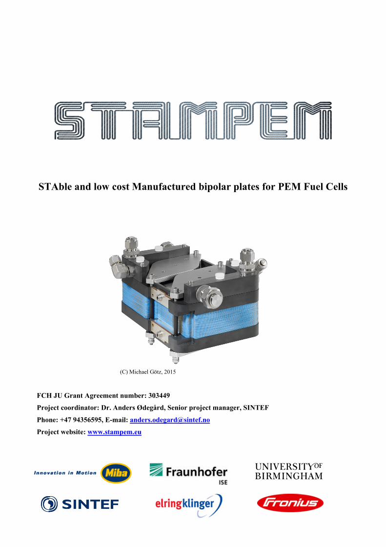
STAble and low cost Manufactured bipolar plates for PEM Fuel Cells
(C) Michael Götz, 2015
FCH JU Grant Agreement number: 303449
Project coordinator: Dr. Anders Ødegård, Senior project manager, SINTEF
Phone: +47 94356595, E-mail: [email protected]
Project website: www.stampem.eu

2
TABLE OF CONTENTS 1 Executive summary .................................................................................................................... 3 2 Project context and objectives .................................................................................................. 4 3 Main scientific and technical results ........................................................................................ 6
3.1 Coating development and characterization .......................................................................... 6 3.2 Processing of coatings and serial production aspects .......................................................... 8 3.3 In-situ analysis of coated bipolar plates ............................................................................. 10 3.4 Validation and techno-economical assessment .................................................................. 15
4 Potential impact........................................................................................................................ 18 5 Dissemination activities and exploitation of results .............................................................. 19 6 Further information and contact details ................................................................................ 22
3
1 Executive summary Development of coatings for stainless steel bipolar plates was investigated using four different approaches within this project. These were 1) PVD coatings, investigated by TCL; 2) electrochemically prepared polymer based coatings investigated by UoB; 3) combined GDL-BPP concept and 4) carbon-based coatings investigated by SINTEF. Each of these was developed independently throughout the project, but improvements were achieved in all areas: Great improvements were achieved in corrosion resistance of the new generations PVD coatings. A significant reduction in ICR of the polymer-based coatings was achieved by hybridisation with/addition of TiN particles. A reduction in ICR of the carbon composite coatings was obtained due to an improved application process. The concept of a combined GDL and BPP was also validated in small scale in-situ testing. A metal BPP stack was lifetime tested in a harsh industrial load cycle over 1000 hours and about 1800 start / stop cycles. The industrial load cycle testing was followed by accelerated stress testing over 250 hours and further 1800 start / stop cycles. The gold coated metal BPP reference stack showed a degradation rate of 32 µV/h in the industrial load cycle and 40-60 µV/h during the AST. This result compares to 6 to 9 µV/h degradation rate at typical load cycle testing in the laboratory where no start / stop cycling is applied. A PVD-coated metal BPP stack showed reduced initial performance, probably due to the higher ICR of the bipolar plates. The degradation rate during industrial load cycling was in the range of 56 and 80µV/h. The AST cycle was not completed due to the poor performance of the stack after the industrial load cycle as the current limitations of the test rig were exceeded. The lifetime testing confirms start / stop cycling is an important parameter for stack degradation and a low ICR is a key parameter for overall stack performance. The economic assessment delivered 50 000 stacks as a reasonable market entry scenario for fuel cell application in the material handling market worldwide. The critical volume of manufacturing for achieving competitiveness with lead acid batteries (TCO basis) was found to be in the range of 1000 and 5000 units per year. The contribution of coated metal BPPs for fuel cell system cost reduction was analysed in detail and was subsequently found to be considerable compared to moulded graphite BPP originally used. The cost reduction potential at the BPP level was found to be in the range of 62 - 93% for 50 000 stacks per year for changing from current low volume manufactured moulded graphite BPP to coated metal BPP. For the high volume automotive market with 300 000 stacks per year (representing 150 million BPPs per year), a projected 98% cost reduction potential was identified for the PVD coating system developed within the STAMPEM project. The automotive market scenario delivers 5.35 €/kW for low-cost coated metal BPP which is more than twice the current target of 2.5 €/kW. A further cost reduction of the bipolar plate could be achieved if active area welding is applied in the future. This would eliminate the need for a conductive coating on the inner surfaces of the BPP assembly, thus further reducing the coated area per assembly by a factor of 2. This manufacturing route is not yet fully established, but could be developed in the near future to provide further added value
4
2 Project context and objectives The European Strategic Energy Technology (SET) Plan has identified fuel cells and hydrogen among the technologies needed for Europe to meet the energy efficiency targets for 2020 as well as to realise the long-term vision for 2050 towards decarbonisation. Correspondingly, the FCH JU program, and more specifically the Application Area “Transportation & Refuelling Infrastructure”, aims to pave the road towards the market introduction of fuel cell vehicles. Since the late 1980s Proton Exchange Membrane Fuel Cells (PEMFCs) have been under continuous development with the application in fuel cell vehicles as the main driver. Although PEMFCs technology has matured significantly over the last two decades, their use is still limited to certain niche markets (e.g., forklifts, backup power, telecommunication towers) partly due to subsidies. For large scale deployment of fuel cell vehicles substantial research and development on PEMFCs is still needed to comply with the stringent cost and durability targets. One key component in the PEMFC which contributes significantly to cost and still needs to be improved to ensure cell lifetime is the BiPolar Plate (BPP). The BPP provides the structural integrity of the PEMFC stack and moreover serves three purposes: 1) separation of the fuel and oxidant gases, 2) distribution of reactant gases to the cells and 3) electron flow through the PEMFC stack. For transport/motive power applications, it is clear that metallic plates currently offer the best compromise between electrical and mechanical functionality, weight and space saving, but cannot yet meet the corresponding lifetime and cost requirements. According to DTI’s recent analysis for US Department of Energy, the cost of these BPP are still estimated at $5.68/kWnet for mass production volumes, which is close to twice that of the cost target given in the Topic Description of the current FCH JU-call (2.5€/kW). Lifetime of automotive PEM fuel cell stacks is currently approaching the target lifetime of 5000 hours, but bipolar plates used in these stacks are very expensive as they have a relatively cost intensive coating. Alternative coating materials have not yet been developed to a level that allows commercial use but are needed to achieve long-term stable and commercially viable bipolar plates. Lifetime target for automotive stacks is 5000 hours, whereas for material handling applications more than10 000 hours. The technological challenges facing PEMFCs are of great complexity, requiring substantial investments and a high level of technological expertise. Each component of the PEMFC needs to be scrutinized in the effort of reducing cost and increasing lifetime, without sacrificing performance. As an integral part of the PEMFC stack, the BPP still needs to be improved. The STAMPEM-consortium, comprising a complete value chain, has been established acknowledging that further development of BPPs requires Europe’s best available resources, with respect to human competence and infrastructure (laboratories and relevant industrial facilities) as well as economical impact. The concept of STAMPEM has thus been to combine world leading industrial actors with research institutions with the required generic competence capable of providing breakthrough solutions with respect to a new generation coating for low cost metallic BPPs. By involving an end user of the BPPs developed in the STAMPEM project, the results were thoroughly verified under realistic operating conditions in a PEMFC stack.
5
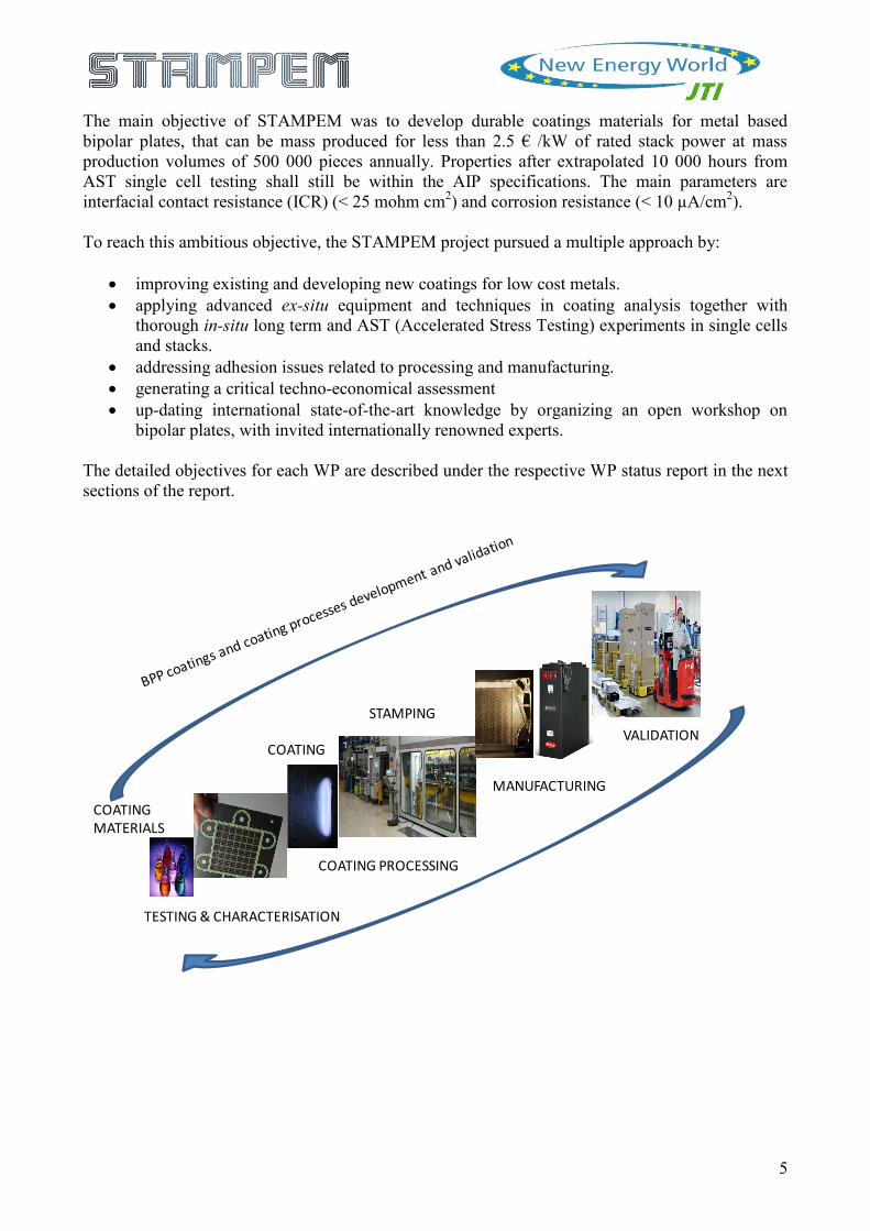
The main objective of STAMPEM was to develop durable coatings materials for metal based bipolar plates, that can be mass produced for less than 2.5 € /kW of rated stack power at mass production volumes of 500 000 pieces annually. Properties after extrapolated 10 000 hours from AST single cell testing shall still be within the AIP specifications. The main parameters are interfacial contact resistance (ICR) (< 25 mohm cm2) and corrosion resistance (< 10 µA/cm2). To reach this ambitious objective, the STAMPEM project pursued a multiple approach by:
• improving existing and developing new coatings for low cost metals. • applying advanced ex-situ equipment and techniques in coating analysis together with
thorough in-situ long term and AST (Accelerated Stress Testing) experiments in single cells and stacks.
• addressing adhesion issues related to processing and manufacturing. • generating a critical techno-economical assessment • up-dating international state-of-the-art knowledge by organizing an open workshop on
bipolar plates, with invited internationally renowned experts. The detailed objectives for each WP are described under the respective WP status report in the next sections of the report.
COATINGMATERIALS
TESTING & CHARACTERISATION
COATING
STAMPING
MANUFACTURING
VALIDATION
COATING PROCESSING
6
3 Main scientific and technical results The scientific work in STAMPEM was divided in these main activities:
• Coating development and characterization • Processing of coatings and serial production aspects • In-situ analysis of coated bipolar plates • Validation and techno-economical assessment
3.1 Coating development and characterization
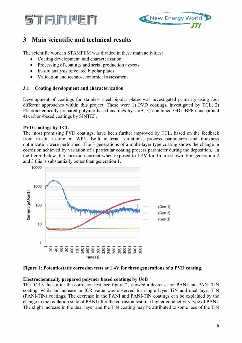
Development of coatings for stainless steel bipolar plates was investigated primarily using four different approaches within this project. These were 1) PVD coatings, investigated by TCL; 2) Electrochemically prepared polymer based coatings by UoB; 3) combined GDL-BPP concept and 4) carbon-based coatings by SINTEF. PVD coatings by TCL The most promising PVD coatings, have been further improved by TCL, based on the feedback from in-situ testing in WP5. Both material variations, process parameters and thickness optimization were performed. The 3 generations of a multi-layer type coating shows the change in corrosion achieved by variation of a particular coating process parameter during the deposition. In the figure below, the corrosion current when exposed to 1.4V for 1h are shown. For generation 2 and 3 this is substantially better than generation 1.
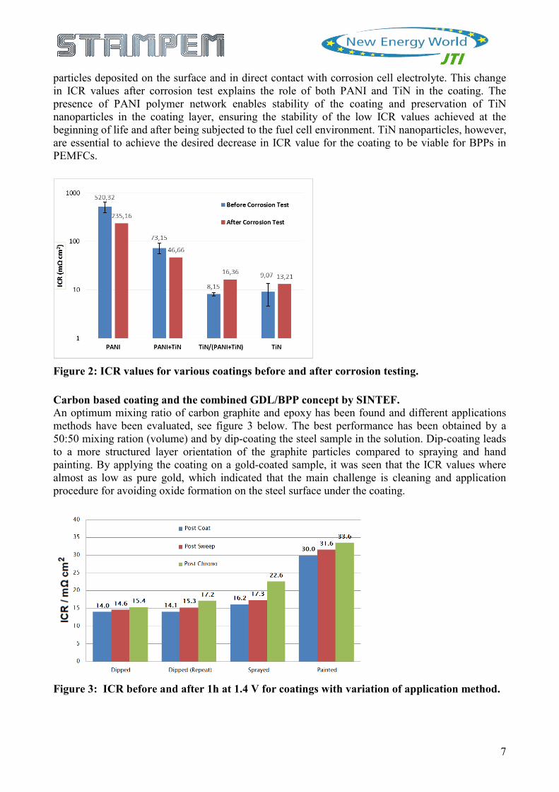
Figure 1: Potentiostatic corrosion tests at 1.4V for three generations of a PVD coating. Electrochemically prepared polymer based coatings by UoB The ICR values after the corrosion test, see figure 2, showed a decrease for PANI and PANI-TiN coating, while an increase in ICR value was observed for single layer TiN and dual layer TiN (PANI-TiN) coatings. The decrease in the PANI and PANI-TiN coatings can be explained by the change in the oxidation state of PANI after the corrosion test to a higher conductivity type of PANI. The slight increase in the dual layer and the TiN coating may be attributed to some loss of the TiN
7
particles deposited on the surface and in direct contact with corrosion cell electrolyte. This change in ICR values after corrosion test explains the role of both PANI and TiN in the coating. The presence of PANI polymer network enables stability of the coating and preservation of TiN nanoparticles in the coating layer, ensuring the stability of the low ICR values achieved at the beginning of life and after being subjected to the fuel cell environment. TiN nanoparticles, however, are essential to achieve the desired decrease in ICR value for the coating to be viable for BPPs in PEMFCs.
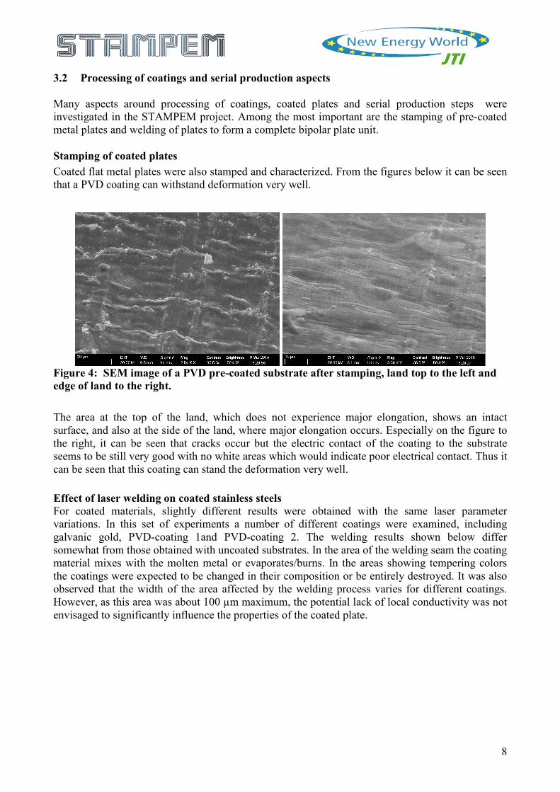
Figure 2: ICR values for various coatings before and after corrosion testing. Carbon based coating and the combined GDL/BPP concept by SINTEF. An optimum mixing ratio of carbon graphite and epoxy has been found and different applications methods have been evaluated, see figure 3 below. The best performance has been obtained by a 50:50 mixing ration (volume) and by dip-coating the steel sample in the solution. Dip-coating leads to a more structured layer orientation of the graphite particles compared to spraying and hand painting. By applying the coating on a gold-coated sample, it was seen that the ICR values where almost as low as pure gold, which indicated that the main challenge is cleaning and application procedure for avoiding oxide formation on the steel surface under the coating.
Figure 3: ICR before and after 1h at 1.4 V for coatings with variation of application method.
8
3.2 Processing of coatings and serial production aspects
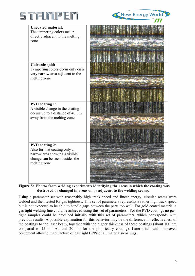
Many aspects around processing of coatings, coated plates and serial production steps were investigated in the STAMPEM project. Among the most important are the stamping of pre-coated metal plates and welding of plates to form a complete bipolar plate unit. Stamping of coated plates Coated flat metal plates were also stamped and characterized. From the figures below it can be seen that a PVD coating can withstand deformation very well.
Figure 4: SEM image of a PVD pre-coated substrate after stamping, land top to the left and edge of land to the right.
The area at the top of the land, which does not experience major elongation, shows an intact surface, and also at the side of the land, where major elongation occurs. Especially on the figure to the right, it can be seen that cracks occur but the electric contact of the coating to the substrate seems to be still very good with no white areas which would indicate poor electrical contact. Thus it can be seen that this coating can stand the deformation very well. Effect of laser welding on coated stainless steels For coated materials, slightly different results were obtained with the same laser parameter variations. In this set of experiments a number of different coatings were examined, including galvanic gold, PVD-coating 1and PVD-coating 2. The welding results shown below differ somewhat from those obtained with uncoated substrates. In the area of the welding seam the coating material mixes with the molten metal or evaporates/burns. In the areas showing tempering colors the coatings were expected to be changed in their composition or be entirely destroyed. It was also observed that the width of the area affected by the welding process varies for different coatings. However, as this area was about 100 µm maximum, the potential lack of local conductivity was not envisaged to significantly influence the properties of the coated plate.
9
Uncoated material: The tempering colors occur directly adjacent to the melting zone
Galvanic gold: Tempering colors occur only on a very narrow area adjacent to the melting zone
PVD coating 1: A visible change in the coating occurs up to a distance of 40 µm away from the melting zone
PVD coating 2: Also for that coating only a narrow area showing a visible change can be seen besides the melting zone
Figure 5: Photos from welding experiments identifying the areas in which the coating was
destroyed or changed in areas on or adjacent to the welding seams. Using a parameter set with reasonably high track speed and linear energy, circular seams were welded and then tested for gas tightness. This set of parameters represents a rather high track speed but is not expected to be able to handle gaps between the parts too well. For gold coated material a gas tight welding line could be achieved using this set of parameters. For the PVD coatings no gas-tight samples could be produced initially with this set of parameters, which corresponds with previous results. A possible explanation for this behavior may be the difference in reflectiveness of the coatings to the laser beam, together with the higher thickness of these coatings (about 100 nm compared to 15 nm Au and 20 nm for the proprietary coating). Later trials with improved equipment allowed manufacture of gas tight BPPs of all materials/coatings.
10
3.3 In-situ analysis of coated bipolar plates
Experiments ranging from small scale single cell testing to full size stack testing was conducted to evaluate the developed coatings. In addition, a cell set up which allowed operation under temperature gradients similar to stack conditions was developed to make sure that results of full-size single cell tests were relevant for stack operation. Furthermore a spatially resolved in situ performance measurement in a full size single cell has been done, in order to identify the critical parts of the bipolar plate. Small scale, single cell in-situ testing Three different protocols were applied during single cell testing in the STAMPEM project. These are summarized in the table below. In the first series of measurements, using protocol 1, low gas flow rates were employed. The test consisted in 100 h voltage cycling using a customized fuel cell test station. In the second set of experiments the AST protocol was adjusted. The same customized fuel cell test station was used, but this time high gas flow rates were employed. The test also consisted in 100 h of current density cycling. Finally, in the last series of experiments, a commercial Greenlight fuel cell test station was used. The duration of the test was increased to 200 h current density cycling, the time at open circuit was reduced and the test also included fuel cell start-up and shut-down cycles. The idea behind Protocol 1 was to use operating parameter as close as possible to real stack operation, especially with regards to gas stoichiometry. The idea behind Protocol 2 was to have better performance and increase the stability of the single cell fuel cell, gas stoichiometry was increased and current density instead of voltage was controlled in order to have control of the water production. Finally, the idea behind protocol 3 was to closely simulate real fuel cell operation. Table 1 AST protocols for in-situ, small-scale testing of BPPs and coatings.
Protocol 1 Protocol 2 Protocol 3
MEA Gore Primea FCM Gore Primea FCM Gore Primea FCM
GDL H2315 C6 H2315 C6 H2315 C6
Clamping Pressure 3.1 bar 3.1 bar 2 bar (166 N cm-2)
gas anode H2 H2 H2
gas cathode air air air
Back pressure anode 0.2 0.2 0.2
Back pressure cathode 0.3 0.3 0.3
Stoich anode 2 3 3
Stoich cathode 2 5 5
Flow at OCV anode 0.1 0.2 0.2
Flow at OCV cathode 0.2 0.3 0.3
Cell temp 70 70 70
Pippe temp 75 75 75
Dp temp 70 68 68
AST Time and current/voltage per cycle
20 min OCV, 20 min 0.4 V 10 min OCV, 30 min 1.2 A cm-2
1 min OCV, 30 min 1.2 A cm-2, 10 min 0.5 A cm-2 and 5 min shut down
11
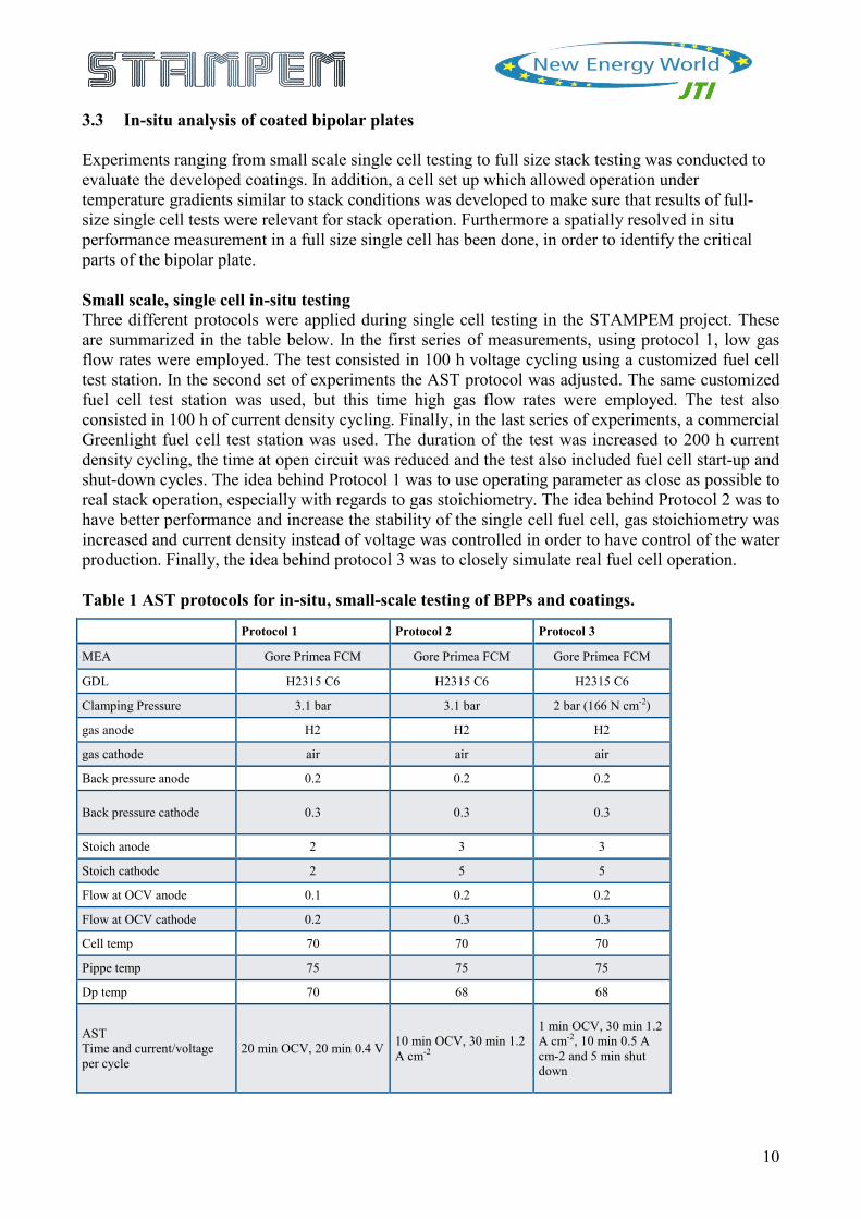
The new operating conditions result in an overall more stable performance, allowing for better characterization of the initial performance of the fuel cell.
Figure 6: Specific ICR @ 166 N cm-2 (land area 6.19 cm2), before and after AST. As it was already suspected from the in-situ high frequency resistance (HFR) measurements, there were only small changes in ICR of the BPPs after the AST, as shown in Figure 6. However, in the case of the PVD-2, there was a small but measurable increase both the in-situ HFR and the ex-situ ICR, which could be related to an actual degradation of the coating. Detailed SEM and EDS analysis was performed on all the samples. However, it was difficult to identify or conclude actual coating degradation, as all BPP showed some level of defects both before and after the AST. The degradation of the cathode catalysts was found using cyclic voltammetry. All fuel cells, independent of the BPP, showed a considerable decrease in ECSA and the main cause for fuel cell performance degradation. Furthermore, it was also found that some of the degradation may be attributed to an increase of the hydrogen crossover rate through the membrane. Adjusted operating conditions allowed for a deeper in-situ electrochemical characterization, e. g. the used of EIS in order to measure the resistance of the cell. Additionally, it was possible to directly correlate the in-situ performance of the fuel cell with measured ICR values. Both the 100 h and 200 h tests (protocol 2 and 3) showed that the main degradation mechanism of these fuel cells was loss of electrochemical active surface area, e. g. Pt agglomeration, dissolution and/or detachment from the cathode catalyst layer. This degradation is not attributed to the BPP materials used, but a combination between the specifics of the AST protocols and the experimental hardware. All coatings seemed to give a certain degree, but not a full, protection against corrosion. This was based on that all MEA analysed post-mortem showed an increase in Fe content compared to pristine MEAs. However, these levels were considerably lower compared to the MEAs used with uncoated BPPs. In addition, the test stations also release a certain amount of ions which makes the quantification very complicated. From the small scale, single cell testing it could be concluded that all PVD coated plates were promising coating materials for further studies in full size single cell or short stack testing, and they are well suited for +1000 h testing. However, there some batches of PVD coated plates showed higher ICR values.
12
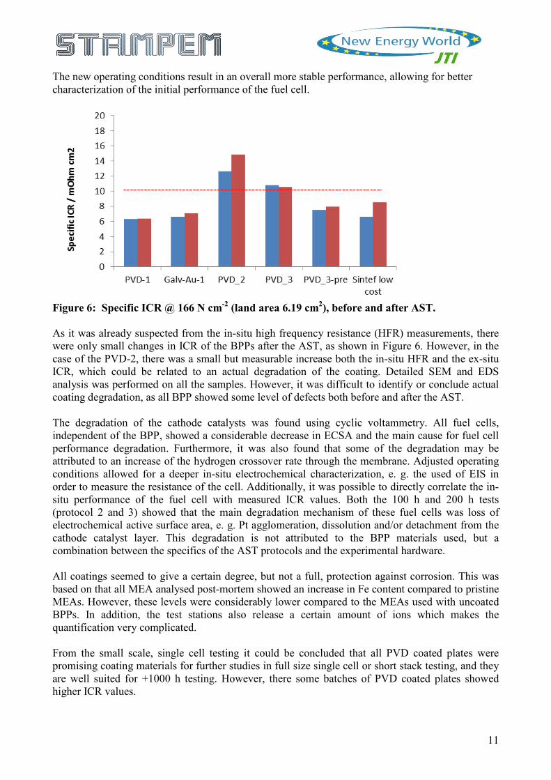
Spatially resolved in-situ characterisation with real single cell design in full size The segmented cell performance corresponded very well with the performance of the average cell performance in the stack operated at Elring Klinger. Considering the complexity of the segmented setup, this significantly increased the confidence that the segmented cell results correspond very well to the conditions in the stack.
Figure 7: Complete cell setup with upper isolation plate containing holes for the contact pins.
Spatially resolved current generation during the potentiostatic steps of 0.75 V and 0.45 V is shown in Figure 7. A significant gradient can be observed from air inlet to air outlet with a current of less than 50% at the outlet compared to the inlet. Furthermore, the current generation of the boundary segments at the long side of the cell is significantly lower than the segments towards the middle of the cell. The reduced performance of the boundary segments can either originate from inhomogeneous gas supply in the flow fields, from inhomogeneous cell compression or from cross currents between segments in the segmented setup.
Figure 8: Current distribution at two potentiostatic points (top: 0.75V, bottom: 0.45V).
13
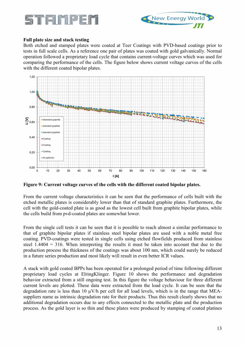
Full plate size and stack testing Both etched and stamped plates were coated at Teer Coatings with PVD-based coatings prior to tests in full scale cells. As a reference one pair of plates was coated with gold galvanically. Normal operation followed a proprietary load cycle that contains current-voltage curves which was used for comparing the performance of the cells. The figure below shows current voltage curves of the cells with the different coated bipolar plates.
Figure 9: Current voltage curves of the cells with the different coated bipolar plates. From the current voltage characteristics it can be seen that the performance of cells built with the etched metallic plates is considerably lower than that of standard graphite plates. Furthermore, the cell with the gold-coated plate is as good as the lowest cell built from graphite bipolar plates, while the cells build from pvd-coated plates are somewhat lower. From the single cell tests it can be seen that it is possible to reach almost a similar performance to that of graphite bipolar plates if stainless steel bipolar plates are used with a noble metal free coating. PVD-coatings were tested in single cells using etched flowfields produced from stainless steel 1.4404 = 316. When interpreting the results it must be taken into account that due to the production process the thickness of the coatings was about 100 nm, which could surely be reduced in a future series production and most likely will result in even better ICR values. A stack with gold coated BPPs has been operated for a prolonged period of time following different proprietary load cycles at ElringKlinger. Figure 10 shows the performance and degradation behavior extracted from a still ongoing test. In this figure the voltage behaviour for three different current levels are plotted. These data were extracted from the load cycle. It can be seen that the degradation rate is less than 10 µV/h per cell for all load levels, which is in the range that MEA-suppliers name as intrinsic degradation rate for their products. Thus this result clearly shows that no additional degradation occurs due to any effects connected to the metallic plate and the production process. As the gold layer is so thin and these plates were produced by stamping of coated platines
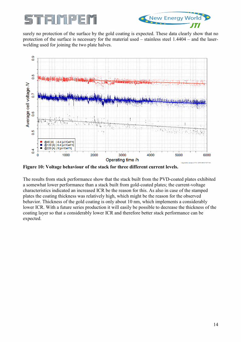
14
surely no protection of the surface by the gold coating is expected. These data clearly show that no protection of the surface is necessary for the material used – stainless steel 1.4404 – and the laser-welding used for joining the two plate halves.
Figure 10: Voltage behaviour of the stack for three different current levels. The results from stack performance show that the stack built from the PVD-coated plates exhibited a somewhat lower performance than a stack built from gold-coated plates; the current-voltage characteristics indicated an increased ICR be the reason for this. As also in case of the stamped plates the coating thickness was relatively high, which might be the reason for the observed behavior. Thickness of the gold coating is only about 10 nm, which implements a considerably lower ICR. With a future series production it will easily be possible to decrease the thickness of the coating layer so that a considerably lower ICR and therefore better stack performance can be expected.
15
3.4 Validation and techno-economical assessment
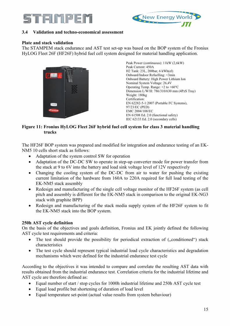
Plate and stack validation The STAMPEM stack endurance and AST test set-up was based on the BOP system of the Fronius HyLOG Fleet 26F (HF26F) hybrid fuel cell system designed for material handling application.
Peak Power (continuous): 11kW (2,6kW) Peak Current: 450A H2 Tank: 23L, 200bar, 6 kWh(el) Onboard/Indoor Refuelling: <3min Onboard Battery: High Power Lithium Ion Nominal System Voltage: 26,4V Operating Temp. Range: +2 to +60°C Dimension L/W/H: 786/310/630 mm (4PzS Tray) Weight: 180kg Certification: EN 62282-5-1:2007 (Portable FC Systems), 97/23/EC (PED) EMC 2004/108/EC EN 61508 Ed. 2.0 (functional safety) IEC 62133 Ed. 2.0 (secondary cells)
Figure 11: Fronius HyLOG Fleet 26F hybrid fuel cell system for class 3 material handling trucks
The HF26F BOP system was prepared and modified for integration and endurance testing of an EK-NM5 10 cells short stack as follows:
• Adaptation of the system control SW for operation • Adaptation of the DC-DC SW to operate in step-up converter mode for power transfer from
the stack at 9 to 6V into the battery and load sink voltage level of 12V respectively • Changing the cooling system of the DC-DC from air to water for pushing the existing
current limitation of the hardware from 160A to 220A required for full load testing of the EK-NM5 stack assembly
• Redesign and manufacturing of the single cell voltage monitor of the HF26F system (as cell pitch and assembly is different for the EK-NM5 stack in comparison to the original EK-NG3 stack with graphite BPP)
• Redesign and manufacturing of the stack media supply system of the HF26F system to fit the EK-NM5 stack into the BOP system.
250h AST cycle definition On the basis of the objectives and goals definition, Fronius and EK jointly defined the following AST cycle test requirements and criteria:
• The test should provide the possibility for periodical extraction of („conditioned“) stack characteristics
• The test cycle should represent typical industrial load cycle characteristics and degradation mechanisms which were defined for the industrial endurance test cycle
According to the objectives it was intended to compare and correlate the resulting AST data with results obtained from the industrial endurance test. Correlation criteria for the industrial lifetime and AST cycle are therefore defined as:
• Equal number of start / stop cycles for 1000h industrial lifetime and 250h AST cycle test • Equal load profile but shortening of duration of load level • Equal temperature set-point (actual value results from system behaviour)
16
1000h endurance test definition The STAMPEM BPP endurance and lifetime test started with the definition of a suitable load cycle derived and representing industrial material handling conditions. In addition HF26F system requirements and limitations as well as evaluation procedure requirements were taken into account. Fronius and EK jointly defined the following lifetime cycle test requirements and criteria:
• The test cycle represents typical industrial load cycle conditions, characteristics and degradation mechanisms
• The industrial endurance cycle test duration (min. 1000h) should be substantially longer than the typical break-in time for a new stack hardware
• The stack test procedure and load profile should provide the possibility for periodical extraction of („conditioned“) stack characteristics
• A correlation between industrial endurance life cycle testing and accelerated stress testing of stack hardware should be investigated
Operation conditions which are dominating (non-recoverable) degradation – and therefore should be represented by the endurance test cycle applied – were identified as follows:
• Start / stop cycling • Extreme part-load conditions (OCV) • Fast load cycling (local fuel starvation, temperature deviation) • High current densities (membrane thinning and degradation, membrane drying, reactants
transport limitations) • Upper-limit temperature operation
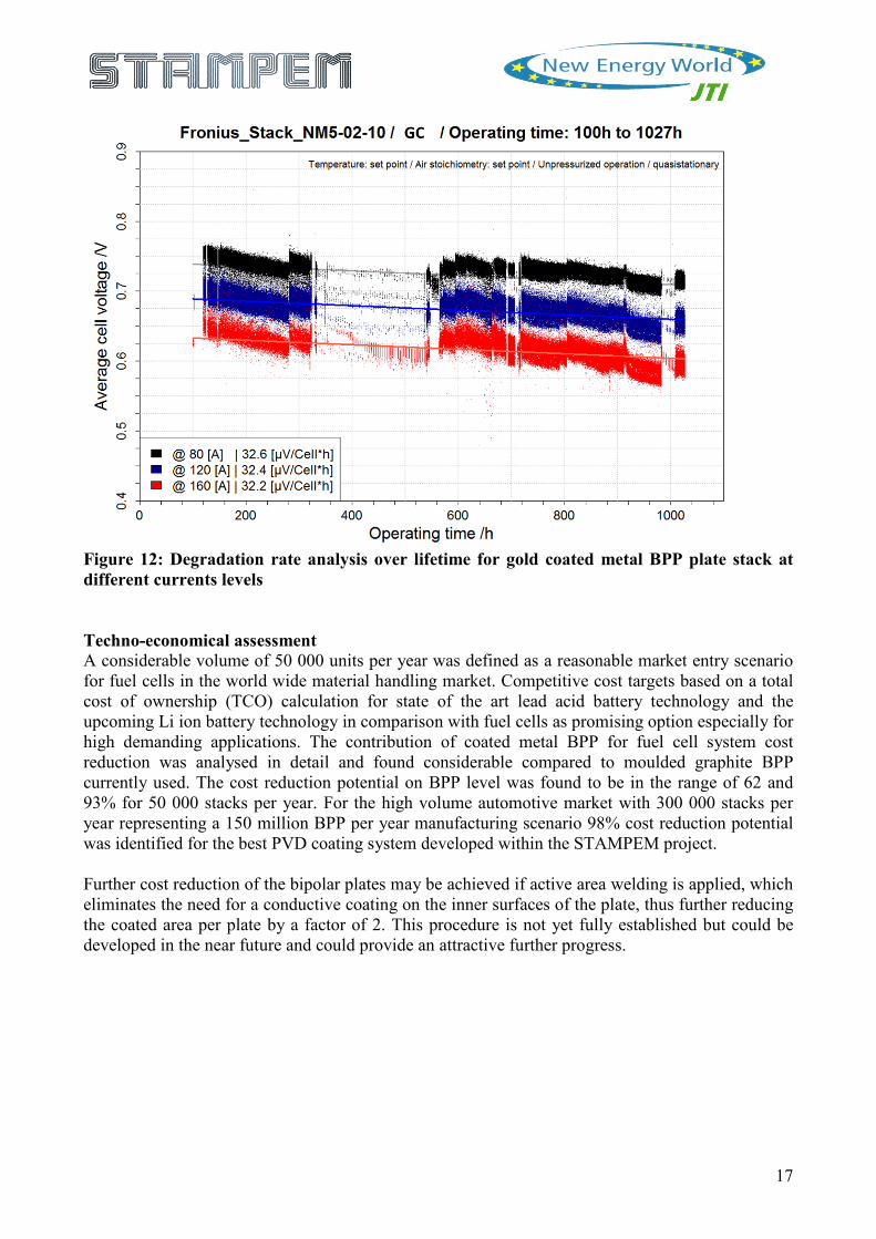
A standard heavy duty load cycle test (“OEM Cycle”) for class 3 warehouse trucks was chosen as a basis for extracting and further developing the “industrial endurance test cycle” which fulfils the requirements and criteria defined above. Degradation rate analysis Degradation rates for the gold coated and PVD coated BPP were analysed in detail over the industrial test cycle. The results for the gold coating is given in figure 12. The degradation rate for the gold coated stack in the industrial load cycle is in the range of 32 µV/h and almost independent for typical stack currents in the range of 80 to 160A. The almost constant degradation for different stack currents is unusual and could result from activation losses due to the 10h OCV failure at the very beginning of the endurance testing. The 250 hour AST, which was designed to represent a 1000 hour test, led to 10 to 15 mV degradation of the cell voltage with the gold coated stack, which is equivalent to 40-60 µV/h. From the stack operation at ElringKlinger 10 µV/h would be the normal degradation for ElringKlinger’s load cycle in the laboratory. However, for the Fronius load cycle 32 µV/h were extracted from the experimental data as depicted in figure 12, so the degradation achieved with the AST was a little lower than the equivalent. For the stack built with the best PVD-coatings a performance considerably lower than that of the stack with the gold-coated plates was achieved. The difference in cell voltage is about 30 to 40 mV lower than that of a plate with gold coating; this was confirmed by test operation of this test at ElringKlinger prior to and after operation of this stack at Fronius, as also commented earlier in this report.
17
Figure 12: Degradation rate analysis over lifetime for gold coated metal BPP plate stack at different currents levels Techno-economical assessment A considerable volume of 50 000 units per year was defined as a reasonable market entry scenario for fuel cells in the world wide material handling market. Competitive cost targets based on a total cost of ownership (TCO) calculation for state of the art lead acid battery technology and the upcoming Li ion battery technology in comparison with fuel cells as promising option especially for high demanding applications. The contribution of coated metal BPP for fuel cell system cost reduction was analysed in detail and found considerable compared to moulded graphite BPP currently used. The cost reduction potential on BPP level was found to be in the range of 62 and 93% for 50 000 stacks per year. For the high volume automotive market with 300 000 stacks per year representing a 150 million BPP per year manufacturing scenario 98% cost reduction potential was identified for the best PVD coating system developed within the STAMPEM project. Further cost reduction of the bipolar plates may be achieved if active area welding is applied, which eliminates the need for a conductive coating on the inner surfaces of the plate, thus further reducing the coated area per plate by a factor of 2. This procedure is not yet fully established but could be developed in the near future and could provide an attractive further progress.
18
4 Potential impact The main objective of the project STAMPEM, was to develop a new generation low cost coating for metallic bipolar plates in PEM fuel cells, which is in line with the SET-vision to establish hydrogen as an energy carrier in a large range of applications in the near future. According to the SET-plan, it is crucial to “develop the technologies and create the conditions to enable industry to commercialize hydrogen and fuel cell vehicles” within the next 10 years to realise the 2050 vision of a low-carbon economy. Hence, the STAMPEM project results can contribute to the puzzle needed to not only generate the reduction of green house gas (GHG) emissions, but also to facilitate the implementation of the SET-plan. Performancewise the PEM fuel cell technology has already proven competitive with conventional combustion technologies. However, cost and durability still represent significant obstacles to full commercialization of PEM fuel cell technology for automotive applications. Bipolar plates, providing the structural integrity of a PEM fuel cell stack, are not an exception, as today’s applied materials are currently still too costly to manufacture and less expensive alternatives lack the required corrosion stability and interfacial contact resistance to comply with lifetime targets. PEM fuel cell development and sales have been dominated by North American and Japanese manufacturers. STAMPEM was, thus, aiming at providing a significant non-technical impact by supporting European industry to become a competitive technology provider of PEM fuel cell stacks based on European based components, thereby securing work places and value creation as well as the environmental benefits brought about by introduction of this novel technology. STAMPEM output supports commercialisation possibilities on two levels:
• Firstly, the already existing BPP and fuel cell related products by EK, TCL and FRO will have a great potential for further technological improvement and cost reduction.
• Secondly, by increased competence in generic components such as coatings and coating processes, which may be applied in other areas of application, e.g. in the electronic and automobile (corrosion protection) industry, the partners increased knowledge/IP increase the potential for further value creation. The future manufacture and sales of the associated industrial coating equipment, itself an example of a European High Value Manufacturing product, will also create additional value.
Finally, STAMPEM established a partnership of industry and research along the value chain of BPP development, manufacturing and application. A common understanding, interlinked requirement specifications and parameters including test methods were developed which support effectively ongoing research activities.
19
5 Dissemination activities and exploitation of results Information to the public The project web site, www.stampem.eu, was established already in month 1 and has been updated on a regular basis. The sections "Publications" and "News and Events" list published journals and presentations as well as information about the relevant BPP workshops arranged.
Contribution to the scientific community Two articles have been published, where some of the work has been performed in STAMEPM:
• "Carbon-polymer composite coatings for PEM fuel cell bipolar plates" H. Husby, O. E. Kongstein, A. Oedegaard, F. Seland, Int J. Hydrogen Energy 39 (2014)
• "An investigation of the typical corrosion parameters used to test polymer electrolyte fuel cell bipolar plate coatings, with titanium nitride coated stainless steel as a case study", A. Orsi, O.E. Kongstein, P.J. Hamilton, A. Oedegaard, I.H. Svenum, K. Cooke, Journal of Power Sources (2015), pp. 530-537
At least three more articles are under preparation and expected to be submitted in 2015 or early 2016:
• "Corrosion of carbon coated stainless steel for bipolar plates in PEM fuel cells" R. Milliken, I. D. Hidalgo, O. E. Kongstein, P. J. Hamilton, A. Oedegaard and K. Cooke
• "Influence of Temperature on growth and properties of PANI coatings on SS316.", UoB
• "Optimisation of TiN-PANI coating" and "The interaction between TiN and Polyaniline, UoB
A list of presentations on the STAMPEM work given by the project partners::
• U. Maier, Elring Klinger, "Stacks and stack components", 13th Ulm ElectroChemical Talks, 2012, July 5th, Ulm Germany
• R. Alink, Fraunhofer ISE, "STAMPEM - degradation issues regarding mobile fuel cells", FCH JU workshop: Degradation of PEM Fuel Cells - experience exchange and discussions", 2013, April 3rd +4th, Oslo, Norway
• A. Ødegård, SINTEF, "New concept and coating for PEMFC metallic bipolar plates", HFC Nordic 2013, Nov 1st, Oslo, Norway
• P. Hamilton, Teer Coatings ltd, "Developments in PVD coatings for PEM Fuel Cell Bipolar Plates", F-Cell 2013, October 1st -2nd, Stuttgart, Germany
• D. Gonzalez, UoB, “PANI as a protective coating for PEM bipolar plates” Hydrogen & Fuel Cell SUPERGEN Researcher Conference 2013 Dec 16-18th , poster
• A. Ødegård, SINTEF, STAMPEM project, FCH JU Review Days 2013
• T. Aarhaug, SINTEF, ASME 2014 8TH International Conference on Energy Sustainability and 12th Fuel Cell Science, June 2014, "Carbon-based coatings for PEMFC metal bipolar plates", poster
20
• A. Oyarce, SINTEF, CARISMA Dec 2014 Cape Town South Africa, "Development of a low cost carbon-based coating for PEMFC metal bipolar plates"
• A. Ødegård, SINTEF, STAMPEM project, FCH JU Review Days 2014
• D. Gonzalez, S. Sharma, UoB, 10th International Hydrogen & Fuel Cell Technical Conference, Fuel cells & Hydrogen for future transport & Buildings, 26-27th March 2014, Birmingham, poster
• A. El-kharouf, UoB, 9th NANOSMAT 2014, 8-11 September 2014, TiN doped PANI thin coating for stainless steel for polymer electrolyte fuel cell (PEFC) bipolar plates (BPP)
• E. Wahlmüller: Fronius H2 Technologies, Workshop Brennstoffzellen: Markteinführung, Markthemmnisse und F&E-Schwerpunkte, TU Graz, 27. Februar 2014
• E. Wahlmüller: Status of H2 Technologies for Material Handling and Industrial Application @ Fronius, Eco-Mobility 2014, Vienna, 20th and 21st October
• E. Wahlmüller: Status of H2 Technologies for Material Handling and Industrial Application @ Fronius, NOW WS Intralogistik in der Automobil-Produktion – Erfahrungsaustausch zum Einsatz von brennstoffzellenbetriebenen Flurförderzeugen, Berlin, 29. Okt. 2014
• E. Wahlmüller: Status of H2 Technologies for Industrial Application at Fronius, EMPA, Dübendorf, Dec. 11th, 2014
• E. Wahlmüller: Wasserstoffzwischenspeicher - Optionen für KMU und E-Mobilität, EL-Motion 2015 – Fachkongress E-Mobilität für KMU‘s & kommunale Betriebe in Österreich, Austria Trend Hotel Park Royal Palace, 28. & 29. Jänner 2015
• E. Wahlmüller: BZ-Aktivitäten von Fronius im Bereich Material Handling – Wünsche an die Zulieferer, Vortrag VDMA AG Brennstoffzellen / PG NT-BZ, Sitzung München – Unterhaching, 19.03.2015
• E. Wahlmüller: Fronius Hydrogen Solutions, Seminar International Developments of Stationary Fuel Cell Systems, IEA Annex 33 Advanced FCs, Vienna, 22nd April 2015
• E. Wahlmüller: Fronius H2 Technologies for Green Logistics, 3. Treffen des Council für nachhaltige Logistik (CNL) – Fuhrpark der Zukunft, Klima und Energiefonds, 10. Juni 2015
• E. Wahlmüller: Fronius H2 Technologies, Meeting Österreichische Power-to-Gas-Plattform, Fronius SO Thalheim, 1. Juli 2015
• E. Wahlmüller, K. Fronius: Vision „24h Sonne“ – Wasserstoff und Brennstoffzelle als Schlüssel zur Speicherung von erneuerbarer Energie, Wasserstoff und Brennstoffzelle – kommt der Marktdurchbruch? Vortrag beim AK11 Alpbacher Technologiegespräche, 28. Aug. 2015
• P. Hamilton, K. Cooke, S. Field & H. Sun, Teer Coatings, “PVD Bipolar Plate Coatings for Automotive PEM Fuel Cells and the effect of Manufacturing Processes”, SVC, 5-9th May 2014, Chicago
21
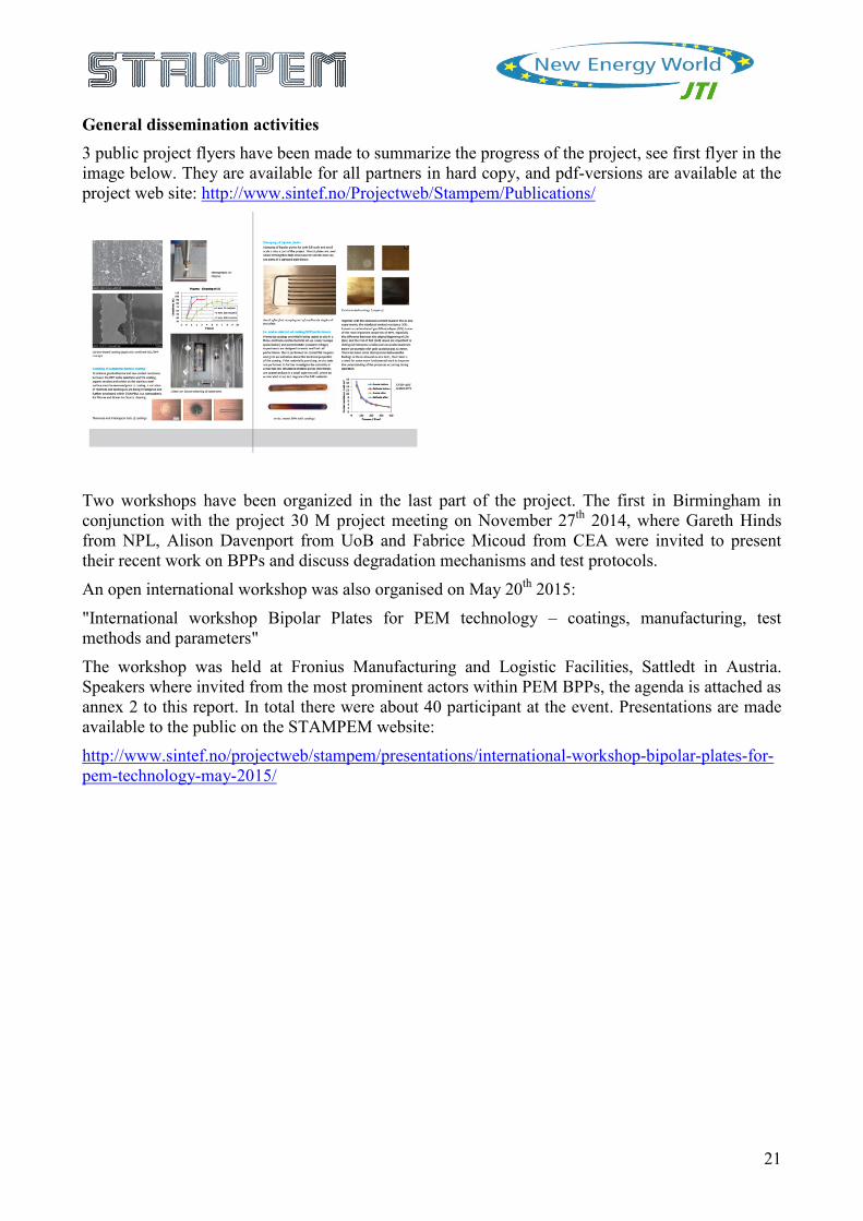
General dissemination activities 3 public project flyers have been made to summarize the progress of the project, see first flyer in the image below. They are available for all partners in hard copy, and pdf-versions are available at the project web site: http://www.sintef.no/Projectweb/Stampem/Publications/
Two workshops have been organized in the last part of the project. The first in Birmingham in conjunction with the project 30 M project meeting on November 27th 2014, where Gareth Hinds from NPL, Alison Davenport from UoB and Fabrice Micoud from CEA were invited to present their recent work on BPPs and discuss degradation mechanisms and test protocols.
An open international workshop was also organised on May 20th 2015:
"International workshop Bipolar Plates for PEM technology – coatings, manufacturing, test methods and parameters"
The workshop was held at Fronius Manufacturing and Logistic Facilities, Sattledt in Austria. Speakers where invited from the most prominent actors within PEM BPPs, the agenda is attached as annex 2 to this report. In total there were about 40 participant at the event. Presentations are made available to the public on the STAMPEM website:
http://www.sintef.no/projectweb/stampem/presentations/international-workshop-bipolar-plates-for-pem-technology-may-2015/
22
Exploitation of results Fuel cell technology is considered as a high potential future technology in the field of stationary as well as automobile applications. In particular the forklift and material handling market, where Fronius is active since more than 60 years with a broad portfolio of high quality battery charging systems, is considered as an attractive and near-term market. The worldwide material handling market is over 900 000 units/a large (source: dfh Journal Intralogistik 2011) and so 50 000 units/a is a reasonable market entry scenario having the potential for substantial cost reduction by volume. Low-cost coated metal BPP are an important step for both cost reduction but also performance improvement (e.g. freeze start capability) of current fuel cell technology. Hence, even new markets could be opened by the STAMPEM project within the medium and long term. The industrial partners MIBA Teer Coatings Ltd and ElringKlinger AG will continue to supply components/parts/materials for stacks, not only to Fronius, but also other end users and applications. For all involved R&D organisations, the developments and gain in knowledge has increased their potential for further cooperation with industry and new projects.
6 Further information and contact details For further information, please visit the project web site: www.stampem.eu
Or contact the project coordinator:
Dr. Anders Ødegård, Senior project manager at SINTEF Phone: +47 94356595 E-mail: [email protected]