Embed Size (px)
Citation preview
j"A010 OR PO10BJ RMEL451
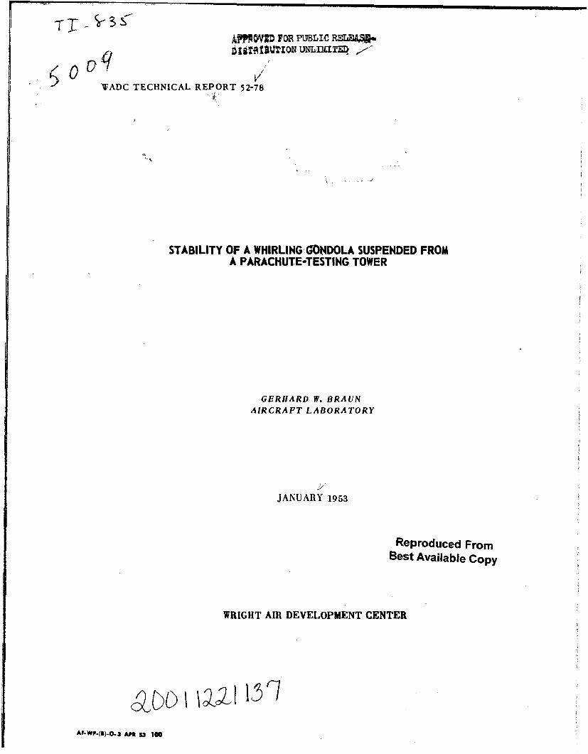
WADC TECHNICAL REPORT 52-78
STABILITY OF A WHIRLING GONDOLA SUSPENDED FROMA PARACHUTE-TESTING TOWER
GERHARD W. BRAUN
AIRCRAFT LABORATORY
JANUARY 1953
Reproduced FromBest Available Copy
WRIGHT AIR DEVELOPMENT CENTER
AF*WP-(I)-.. 3 APN 53 100
NOTICES
When Government drawings, specifications, or other data are usedfor any. purpose other than in connection with a definitely related Govern-ment procurement operation, the United States Government thereby in-cursno responsibility nor any obligation whatsoever; and the fact thatthe Government may have formulated, furnished, or in any way suppliedthe said drawings, specifications, or other data, is not to be regardedby implication or otherwise as in any manner licensing the holder orany other person or corporation,or conveying any rights or permissionto manufacture, use, or sell any patented invention that may in anywaybe related thereto.
The information furnished herewith is made available for studyupon the understanding that the Government's proprietary interests inand relating thereto shall not be impaired. It is desired that the JudgeAdvocate (WCJ), Wright Air Development Center, Wright-PattersonAir Force Base, Ohio, be promptly notified of any apparent conflict be-tween the Government's proprietary interests and those of others.
WADC TECHNICAL REPORT 52-78
STABILITY OF A WHIRLING GONDOLA SUSPENDED FROMA PARACHUTE-TESTING TOWER
Gerhard W. BraunAircraft Laboratory
January 1953
CEO.- C-03
Wright Air Development CenterAir Research and Development Command
United States Air ForceWright-Patterson Air Force Base, Ohio
FOREWORD.
The investigation described in this report was conducted bythe Aerodynamics Branch of the Aircraft Laboratory, AeronauticsDivision, Wright Air Development Center. The work was initiatedby a Suborder dated 12 December 1951 initiated by Mr. J. H. Allenof the Equipment Laboratory, WADC. The CEO No. is C-03.
The model tests were performed by the Dynamic Model Unit underthe direction of Major A. J. Stolzenberger. The performance calcula-tions, evaluation of the photographic records of the model tests, allthe drawings, and an independent check of all numerical calculationsincluded in this report were made by 1st Lt E. D. Wong. This helpis gratefully acknowledged herewith by the author.who acted as projectengineer.
WADC TR 52-78
ABSTRACT
This report investigates the stability of a gondola suspendedfrcm the whirl arm of the Parachute Test Tower at El Centro,California (see Fig. 1) on which instability had been observed.
The work was started with an investigation of the pendulumoscillations of the gondola neglecting the coupling between the twomodes. -The result, that both frequencies become equal at approximatelythe speed at which the instability had been observed, was interpretedas an inclination towards instability. Therefore a more detailedinvestigation including the coupling between the two pendulum modeswas made.
The detailed investigations showed that the damping of thependulum modes is extremely low. Stability, however, is secured ifthe gondola has longitudinal static and weathercock stability and ifthe slope of its cross force versus angle of yaw, is smalerthan the drag coefficient of the gondola plus cable.
Tests made on a 1:20 scale model of the parachute test towerverified the essential parts of the theoretical investigations, namelythe predicted dynamic-stability, the low damping and the order ofmagnitude of the frequencies.
PUBLICATION REVIEW
This report has been reviewed and is approved.
FOR THE COWANDING GENERAL:
SColonel.,USAFChief, Aircraft LaboratoryAeronautics Division
WADC TR 52-78 iii

CONTENTS
PageForeword ......... ............ . . . . .. iiAbstract. . . .... . . . . . . . . . ............... iiiContents . . . . . . . . . . . . . . . . . .. iv
List of Figures . . . .................... vSymbols ..... ................... viIntroduction .................. 1The Equipment ................. 1The Problem. ................ .4Theoretical Investigations .. ..... 8
Performance Considerations . . . ...... . 8Shape of the Cable Under Steady Motions .. .... 9
a. Equilibrium Position Under the Assumption of aStraight Line Cable Shape . . . . . 11
b. Deviation of Cable Shape from Straight Line . o 12The Pendulum Modes as Uncoupled Degrees of Freedom . o 17
a. Outward-Inward Oscillations .. . . . . .. 17b. Fore and Aft Oscillations . . . . .... 17
Derivation of the Equations of Coupled Motion . .... 20Linearization and Nondimensionalization of the
Equations of Motion . . . . o o . . . 27Stability of the Coupled Pendulum Degrees of Freedom. . . 32
Model Tests _ . . . . .0. . . . ... .. 34Dynamic Similarity . . . .. ....... 35Model Test Equipment . . . ........ 35Evaluation of the Tests . ... . . • 44
Explanation of the Observed Instability ... . . . . 48Conclusions and Recommendations . . . . . . . . . 48
Table I .27. . .. . . .. .. . . . . . . 52Table II .. .. .. . . . . . ........ * 53Table III . .. .. .. .. . . . ... 0... 54
WADC TR 52-78 iv

LIST OF FIGURES
Fig. 1 Parachute Test Tower at El CentroFig. 2 GondolaFig. 3 Cables and Sheathing Cross Section With Which Instability
Had Been ObservedFig. 4a The "Tangential Plane" and the "Radial Plane"Fig. 4b Definition of the Angles Jo, %, ,Z, 4.j, 9%4, Describing
The Position In Space of the GondolaFig. 5 Required Power for Two Different Cable DragsFig. 6 Forms of Dynamically Stable SheathingsFig. 7 Cable Forces for the Assumption of a Straight Cable ShapeFig. 8 Relation Between Cable Angle %o and Angular Velocity c of
the Whirling ArmFig. 9 Coordinate System for Curved Cable ShapeFig. 10 Shape .9(1) of Cable in a Radial Plane for an Average Cable
Angle of 0o = 450Fig. 11 Whirling Period T and the Pendulum Periods TI and T2 as
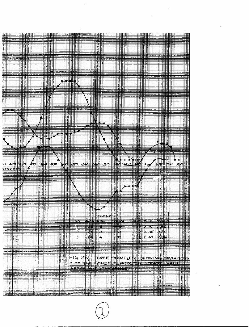
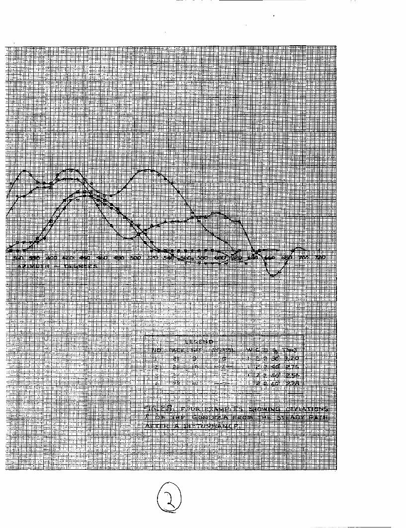
Functions of the Cable Angle %.Fig. 12 The External Forces Acting on the GondolaFig. 13 Division of the Centrifugal Force • Into Three ComponentsFig. 14 Position of the Centrifugal Force Relative to the GondolaFig. 15 Gondola With Heaviest Weight, W3 , and Medium Drag-Plate, D2Fig. 16 Gondola with Heaviest Weight,, (3, and Medium Drag-Plate, D2Fig. 17 The Driving MechanismFig. 18 Model Set-Up Showing Application of DisturbanceFig. 19 Model Set-Up Showing Use of Protractor for Speed AdjustmentFig. 20 View of Overhead CameraFig. 21 View of Ground Camera Showing Model in OperationFig. 22 to 24 Records Taken by the Overhead CameraFig. 25 and 26 Record Taken by the Ground CameraFig. 27 Three Examples of Deviation J of the Gondola from the
Steady Path After a DisturbanceFig. 28 Four Examples of Deviations J of the Gondola From the Steady
Path After a Disturbance
WADC TR 52-78 v
SYMBOLS
A0, Al, A2 , A 3 , A4 0 Coefficients of the frequency polynomial
41i9 G22,.- 4 0 Coefficients of the constant terms in theelements of the frequency polynomial
bll, b1 2 ,...b 1 4 0 Coefficients of the linear terms in thefrequency determinant
(ib) Centrifugal force
C (lb) Aerodynamic cross force
cll, cl2,...c 4 4 0 Coefficients of the quadratic term in thefrequency determinant
CC CCc 0 Cross force coefficient of the gondola
CD 0 Drag coefficient of the gondola includingpart of the cable drag, based on gondolacross-section.
Cm 0 Pitching moment coefficient of gondola
Cn 0 Yawing moment coefficient of gondola
D (lb) Drag
(ft/sec2 ) Acceleration caused by gravitation of theearth
0 = • t nondimensionalized constant ofgravitation
H (ft.lb) Kinetic energy of the gondola
ly, Iz (ft.lb.sec2 ) Gondola moment of inertia about its lateraland vertical axis respectively
S(ft) Length of gondola
(ft) Length of cable
WADC TR 52-78 vi
m lb sec2 /ft Mass of the gondola
M (0) -1 + 4N (0) +
qo, ql, qU, q3, q4 (rad) Angles determining the position of the cableand the gondola in space (see Fig. 4)
Q1 , Q2 , Q3' Q4 ft lb Generalized forces in the Lagrangianequation of motion
R ft Length of the whirling arm
t sec Time
0• = - nondimensionalized time
T sec Turning period of the whirling arm
TI, T2 sec Period of the ql and q2 mode respectively
v ft/sec Velocity of the gondola
W Ib Weight of the gondola
x ft Coordinate in the direction of the cable
y ft Coordinate perpendicular to the directionof the cable.
rad. Angle of attack of the gondola
rad. Angle of yaw of the gondola
cJ ft Deviation of the gondola path from steadystate motion measured in a projection on ahorizontal plane.
0 Damping factor, real part of the complex
frequency, positive for stable motion
0 Length scale factor of the model
0 •---@ mass factor
WAXC TR 52-78 vii
0 4 - . 47,1 j complex frequency
lb sec 2 Mass density of the air
lb sec2 Cable mass per lengthft 2
0 = , nondimensionalized cable mass
T 0 - time factor
(J rad Angular velocity of the whirling armsec
S0 = OZ nondimensionalized angular velocityof the whirl arm
ft 2 Cross section area of the gaondola
Prime ( ) indicate derivatives with respect to T
Nsr (--) above letter indicates either a nondimensional magnitudeee equation 32) or a vector.
Subscript zero (o) indicates a magnitude belonging to the steady statecondition,
WADC TR 52-78 viii

INTRODUCTION
When the Service Branch of the Equipment Laboratory, ;ADC,operated the Parachute Test Tower at El Centro, California for thefirst time, a serious instability was observed at a speed of about50 mph, that is about 1/10 of the design speed. This instabilityprevented further use of the equipment until the stability of thegondola could be improved.
Stability difficulties had not been expected. The test equip-ment had been built on the assumption that it would behave like theparachute test tower owned by Pioneer Parachute Co., Inc. which hadnever shown any difficulties resulting from instability. The twoparachute test towers, that at El Centro and that of Pioneer ParachuteCo., however, are remarkably different in size and are not dnamicallysimilar to each other.
The motion performed by the gondola after a disturbance had notyet been studied either by systematic tests or by analytical investi-gations. It was obvious, however, that the motion of the gondola hada certain similarity to the motion of airplanes. Therefore the Air-craft Laboratory, WADC, was requested to perform a stability investi-gation.
THE EQUIPMENT
The gondola which will be investigated stabilitywise houses aparachute and a dumy of a man. The gondola is designed to be whirledaround a vertical axis with speeds up to 500 mph. The parachute andthe dummy are released when the desired speed is reached.
The dimensions of this parachute testing equipment are given inFig. 1 and 2. The whirling arm has a length of 56 feet and extendshorizontally 120 ft above the ground. The arm is driven by an electricmotor of 2800 HP controlled by the Ward Leonard system. Between theshaft of the driving motor and the axis of the whirling arm there is agear reduction of 22:1. This high gear reduction makes the whirl armself locking. A disturbance of the gondola will not affect the angularvelocity of the arm.
The gondola has a diameter of 28" and is 112" long (see Fig. 2).The center of gravity of the gondola is located 41% of its length behindits nose. Static longitudinal stability and weathercock stability issecured by tailplanes. The gondola is open on its bottom which increasesthe drag of the gondola considerably. The weight of the loaded gondolais W_ - 685 lbs, its empty weight is We - 405 lbs.
WADC TR 52-78 1
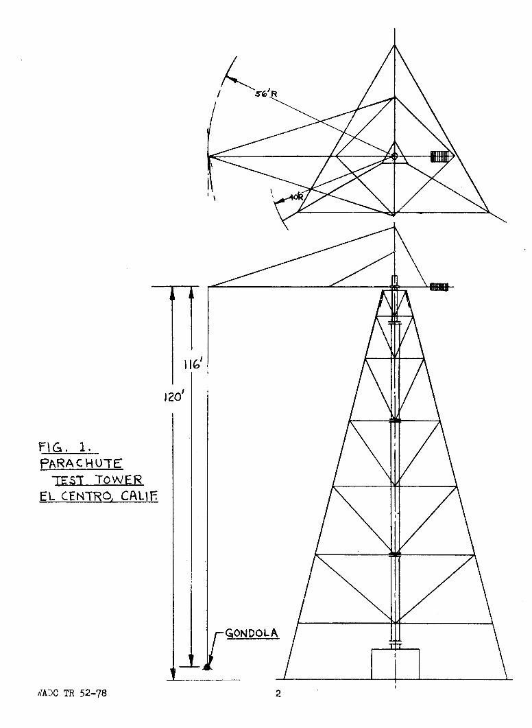
120'
FIG. 1.PARA C HNU-TE
7E0S TOWEREL CENTRO, CAIFr
,T 5
ADC 'T 52-78 R
-j
0~f
<N
)
0ciw
000z NI
1- ~0,
z-10
- IJ - j1
WADC TR 52-783
The gondola is suspended from the end of the whirl arm by oneor more cables of U16 feet length. During the runs showing the instability,a six cable suspension was used. These 6 cables were housed in two stream-lined sheathings, each including 3 cables. The profile of the sheathingswas NACA 0020-63. Fig. 3 shows a cross section through the sheathing andthe cables. The two cable units were attached 19 inches in front of andto the rear of the center of gravity of the gondola.
THE PROBLEK
A solid body moving freely in space has 6 degrees of freedom. Inthe present caso of the gondola, one degree of freedom is eliminated bythe cable, if one assumes that the cable is always kept taut. Thisassumption is made throughout the following investigations.
The remaining five degrees of freedom are coupled with each otherin a manner remarkably different from the free flight conditions. There-fore the experience gained on free flying aircrafts and models cannot beapplied to the stability problem of the gondola. The equations of motionmust be adapted to the present case and solved anew.
It is the purpose of the investigation at hand to analyze the motion,to find out which conditions might cause instability and which precautionsprevent instability, and finally to check the theoretical resultsqualitatively by model tests.
The five rigid body degrees of freedom of the gondola may bedescribed by five angles shown in Fig. 4.
+ -I the angle of the cable measured in a radial plane,that is a vertical plane including the arm; 9.,is the component which belongs to the steadystate conditions. It can be calculated as afunction either of the circumferential velocityor of the angular velocity, CA.), of the whirl arm.
%2 = the angle between the cable and the radial plane,measured in a tangential plane. Precisely speak-ing there is also a steady .state component %a* dueto the drag of the cable and the gondola0 '
but %so is small and will be neglected in thiscalculation.
(43 - the angle of pitch of the gondola measured in thetangential plane from the horizon. If the gondolais trimmed accurately the steady state value 960is zero.
WADC TR 52-78 4
Fig. 4a - The "Tangential Plane" and the "Radial Plane"
The "Radial Plane" is a vertical plane including the arm OP.
The "Tangential Plane" is a plan, containing the end point P of thearm and the tangent of the undisturbed flight path.
WADC TR 52-78 5

p
ý-LTATNrENTIAL PL141E
VIEWED IN THECARECTMON PC4
Fig. 4b - Definition of the angles QW,%1l'9+2 3 s43describing the position in space of the gondola.
WADC TR 52-78 6

S4 the angle between the gondola axis and the tangenton the undisturbed flight path measured in ahorizontal plane. If the point of attachment isdifferent from the center of gravity of the gondolathe centrifugal force will produce a pemanentangle of yaw %40• The same may be caused byunsymmetry of the model or by rudder deflection.In the calculations 9* 40 is assumed to be zero.
%5 the angle of roll measured from the position wherethe c.g. of the gondola is in line with the directionof the cable-end-tangent.
Precisely speaking, these are not all the degrees of freedom sincethe cable has the possibility of moving with an infinite number of modeshapes. These motions can be split up into two components located inthe directions of % 1 and 1 2*
The basic mode shape is very similar to a sttaaght line representedby the cable with an amplitude 9 1 and 9.2 • The higher mode shapeshave nodes and will not be included in the present analysis. They maybe added later in a more extended investigation, if this is required.
A decision had to be made about the type of cable suspension to beinvestigated. The tandem arrangement of the cable units was suspectedfrom the beginning as a possible cause of the observed instability.Therefore a mathematical verification of the instability might be ofinterest. The following reasons, however, prevented the investigationof the double suspension. The cable sheathing was so designed that theaerodynamic center of pressure was located behind the center of gravityof the sheathing and the included cables. Consequently the cable sheathingwould be twisted and high crosswise aerodynamic forces would be producedon the sheathing which could not be neglected. A sufficiently accuratetreatment of these forces, however, would not be possible, since theirregular initial distribution of the twist angle along the cables wasnot known and no data were available about the friction between thedifferent assembly unjits of sheathing. In addition, the mutual aerodynamicinteraction between the sheathing of the two cable units would havecomplicated the calculations. The results, moreover, would have been ofacademic interest only, since it had already been decided to use in thefuture a single cable suspension. Therefore, this investigation isconfined to the single cable suspension.
WADC TR 52-78 7

THEORETICAL INVESTIGATIONS
Performance Considerations
The stability investigation will show that the damping of agondola disturbance is proportional to the drag coefficient of thegondola and cable. Consequently the highest drag would provide the beststability. Therefore it is of interest to find the highest drag coefficientcompatible with the required speed of 500 mph.
For lower speeds the cable angle depends upon the speed. Conse-quently in the low speed range an exact performance calculation becomesinvolved. Fortunately, only high speed cases are of interest for per-formance considerations. For these cases, however, the cable can beassumed stretched horizontally. This assumption has been made in thefollowing calculations.
The total drag of the rotating system is composed of the drag ofthe gondola, the suspension cable, the pipes and wires composing thewhirl arm, and its supports.
All drag components are assumed in the form
fDf IVoi d ,:6)
where /0 is the mass density of air, CD the local drag coefficient,which is. assumed independent from Reynolds and Mach number, x is thedistance of a point from the center of rotation, d is the diameter ofthe part, CO is the angular velocity of the whirl arm. The dimensionsof the framework have been substituted as given in the stress analysisof the tower. The gondola suspension has been assumed as a single cableof 1-7/8 inch diameter. The drag coefficient of all cables and steeltubes has been assumed to be 1.25 based on their frontal area. The dragcoefficient of the gondola is assumed to be 0.2 based on its main crosssection.
The result of these calculations are plotted in Fig. 5. The uppercurve refers to the unsheathed cable, the lower curve to a sheathed cablewith the drag coefficient CD - .24 based on the cable cross section.
The drag of the unsheathed cable causes 87% and the gondola 6-1/2%of the total required power.
WADC TR 52-78 8
T- TFý 4:41- 44+ 4-
#
ttt - 1- 1
jtc
TTMý#FIFF MT 4+H44- -
44.
H 4 + 4
:Ti4+4#t1,-t
4-4-
4-
T
+1 +"-1& -
+
:T4 H- + I -+H4-
fill
ýt! 4+4 ##
tt H, 1' 4,
14
4
it
fl,]Vlif Tý
dl MIR
WADC TR 52-78

The lower drag coefficient of CD = .24 can be realized by using atriangular sheathing as shown inFig. 6. This type of sheatikig is
- - considered cheap in manufacturingcost and upkeep.
Triangular Sheathing
S A still lower drag coefficient canS- be obtained by using a regular
symmetrical wing profile. This,however, will require a mass
Wing Profile Sheathing balance and is considered moreexpensive than the triangular
Fig. 6 Forms of dynamically stable sheathing.Sheathings
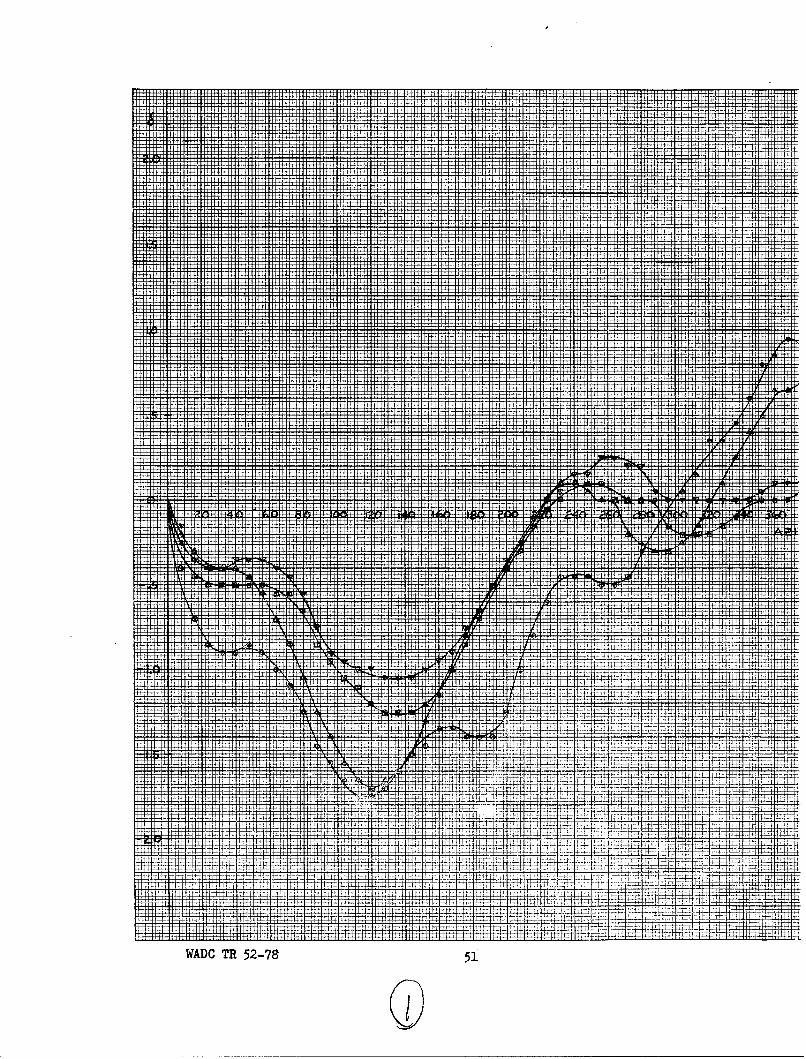
The available power is also shown in Fig. 5. The output of thedriving motor is 2800 HP and the maximum power on the whirling &rm is 2240HP, if a loss of 20% in the total driving mechanism is assumed.
The graph indicates that the required gondola speed of 500 mphcan be obtained, if the drag coefficient of the cable is not higher than.24*.
Shape of the Cable Under Steady Motion
The knowledge of the shape of the cable under steady state con-ditions is important. Only if this shape is known can reasonableapproximations be found and Justified. To begin with, the shape of thecable in the radial plane will be calculated. This is determined bythe weight and the centrifugal forces.
In order to obtain simple conditions, this problem is solved intwo steps. First the equilibrium position of the cable is calculatedunder the assumption that it is a straight line. Secondly the deviationfrom the straight line is calculated and it is shown that this deviationis small.
WADC TR 52-78 IQ
a. Eq4uilibrium position under the assumption of a straifht linecable shape.
0 IP The coordinate along the cableis called x . The origin ofthe coordinates is put at the
AV֥sIng~o)ctJd end point P of the whirl arm.
Equilibrium is obtained, if theG3 0sum of the moments about point P
vanishes. This condition givesthe equation
on (R+tsin tý.)C&)
"Mg.
Fig. 7 Cable forces for the oassumption of a straightcable shape
o5 eqaIon ( az bee plote in +ig 8. Oees slngath
or.
(2)
7C a j
The numerical relation between W.. and 94-.as obtained by evaluationof equation (2) has been plotted in Fig. 8. One sees as long as theangular velocity is small the angle (. changes rapidly withW). Athigher O( however, 4. changes very1ittle and approaches 90°asymptotically.
WADC TR 52-78 13.
....... ...... A ý
4rj rl TI'i it, 4 11, t I
L
:4r- f +F 4 #11 41 T TTT
ITF;
tit, Il't l
'i i I It 1 1 f I I if I I I
A
ul i A
l
M
! I t 1 _tHt 1 - H I Tý!Lý it_1ý , Ri It,[ il lft7 Iý-. H I it I I
U ± H-k I, 1j; 1ý Iý 41 !]l i1;
i i [I I H it! 'it H
I I r it It-- Tt.ýý TIý :Ti
I t I I
r14 iýlj i lil ýýIi ý4, 1
I t 11I ýt !I',; t I I I- Atl if 41it ';I! L f ifI tt . 1ý I IHt I t I T!
I It! t! i t :t IIlk 1 1 1 If] 1, -4llfflli it
ItJ -77 ýR4.- i ;
If 4 jiý t-
if
_Mif
14ý tit
tj IfITIT
tj ifT L
lt - t 1 L, l'i it JI-I! It
_l7[L IT
RIV4 1 1 i, T1
11 - 4ý 4_ý1'ý4 R IT4 - MCI P11t#_V: I 11 1
ji ff
1 i441 E44 k-ý W:41 IN ii'lI fri4 1,t
it4 It
41-P M,4
It f
ýIV4 4it fl liýil
ll;_1 NVIit
"I'Li tljij t T 1 1ý fýIt! I -INI i it I i
V W 11! ll i - I t I i I IA t, - +I Lli :t
fif
It-W 4j411 kf f iif ff, i
idr i liýjIN t"l- (f t-,44 il H t I it+: _Lt I: ilý I I: Ill f 1
ItIM -1 ýi I-t [ýiL i i 1ýj 11 it
VIM 11 Hi Lf ii # t, '41 1; if if 111, ITTilt It tl I ý t, Ii: t t I!
ti ý1flf I if f
LI if I I I' t T I r if 1
I t ;tl II i !tll' I it il
7 4.
f If I14 T I I 174 iI:t1j 111til t-thIiii-t Iff X hý 1iij Tý I i -j t - I - W 1 1 , l
if I,:V: M1 '4;
Iý t ILI-
f ii I itki I
itt I: it
T"
if:ift
]!fit
It,ýiij
4
f47-r 7ý, I j 71 ljiý -11;! 1
LT i " I'-- L I-Il
!j lit Iit 'JL ,IL it it it :;ý:T if iIN Mfli il i ili

b. Deviation of cable shape from straight line.
10 [In order to designate the devia-tion of the cable shape from thestraight line, the coordinate yis used.
The coordinate x is the same asbefore (Fig. 7). It extends fromthe end point, P, of the whirlingarm to the center of the gondola.
Fig. 9 Coordinate system for"curved cable shape
Since the x axis has already the average direction of the cable,the cable slope - will be small. Consequently the length elementis ds =T 3 '+d•• z _. td
The components of the cable tension in x and y directions are
+ +CS10 (3)
'TV /M4v CR + snV1 4) +/92 (it+ T 1r ý R- 5WC0 O
Remembering that ýn ( ný)n CO ( CIO o
WADC TR 52-78 i3
equation (4) can also be written
( + 2_ srn 0,) c oz co S n
+/ýOceck CO~±X
In this form it is epsily seen that Ty changes its sign in theneighborhood of %-Y• , which indicates that the cable curve can notdeviate too much from the straight .line.
The differential equation of the cable curve is
(5)
Cos Qowhich gives after factoring Sir9)
Si- sin 9>iJcO,-(o*,qt) X taf-
-C (Rx-+6 coq. o)x- _ x' -
0
The X2 term in the denominator is removed by dividing by the numerator:
-'L + CC-w4 + (/w +co) Q cot T- ~~ ~ _ .ozst 4o/., __x
After splitting the fraction up into linear partial fractions andintegrating, one obtains
(6)
WADC TR 52-78 14
a+a b
K2 a
a
B /0, , P, -A2 j
/Oc-
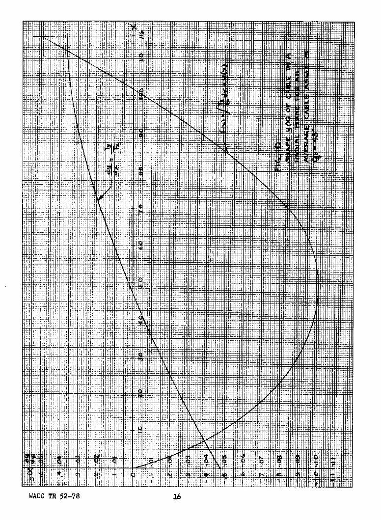
The shape of the cable is plotted in Fig. 10 l•br q. 450,the angle at which the maximum curvature of the cable can beexpected. One sees that the deviation from the straight line isless than 1% of its length. The substitution of the cable shapeby a straight line is thus justified.
WADC TR 52-78 15
-4 4It jill14
Mlmll
, -144#41:il "ttlftll-ý ijlý; ttA Iý Hj4
J -114 1ý I'll I F T,
ifa -if tii TH 4! 11jj jý Iti Ij t
T
J, Willif
it41
if 14 1Iý 4 44T
ýT-if
if t4i
T7t'__i i I
it q 4 t T1'
T !if I
141
i4 I ftj
............ti
1114 Al 444 fp-44+ 1=+"Ift"44, f44
lfý if t 41' l+ +i isatt tý1ý"l I ill;
ýVql tar tlM#iLLL trl V I. f ý' 1111 rT tlM I
i -it I It4 if I
t -11 4 J_' It'j. l ij, .11.
P.1, 14 14, i 44 + ++4f 1 TH
j'j-'4 4
14: 141 tfii ý ! i I - t'ý - - -41; TTI I47t 1ý41 ; ý " - 4 11
111 1 ý E il 14. FL m __m
if
17, 14
jJ7 4" o, t
itI TI T _
H 1fl #:V I ."' -#tl i "
-14
t it, 1 - --------4'
t i'l Vr
_r It '11_;P R41
flf _g ý __1 __: Tý'If I'W 1 4141H 11+ if t I t 1 11 Tl Tl 1, -l"
i J F,
i i: ti tIf t
if! i: Tý; lit ý'11 1 ý' 1 4 :j
44 F-I If 41If ii fj 1 t :I h fifiJýT tý11ý11"Ii w!
it fNI
H , :if 1 L'.; t I till,
4ý 'i4 tt-A
1: if77 1[f i - ' if !ýfi t
WADC TR 52-78 16
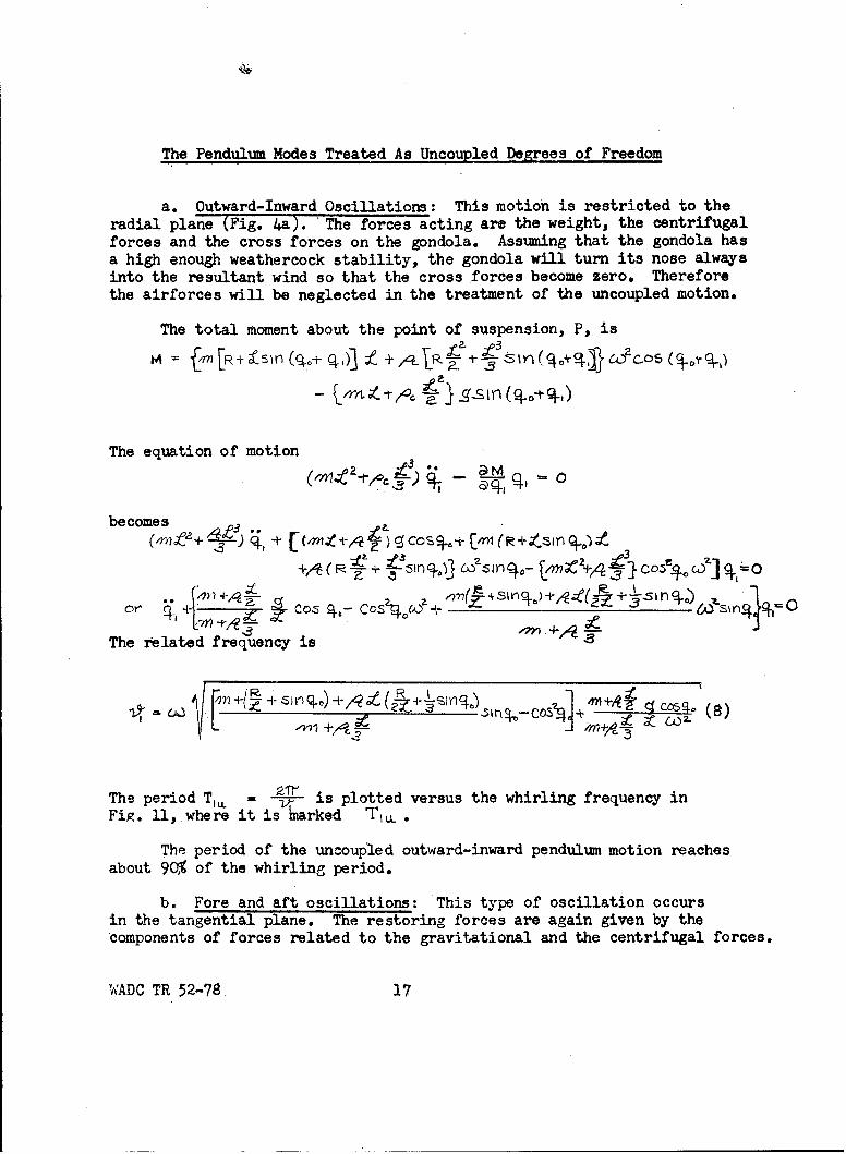
The Pendulum Modes Treated As Uncoupled Degrees of Freedom
a. Outward-Inward Oscillations: This motion is restricted to theradial plane (Fig. 4a). The forces acting are the weight, the centrifugalforces and the cross forces on the gondola. Assuming that the gondola hasa high enough weathercock stability, the gondola will turn its nose alwaysinto the resultant wind so that the cross forces become zero. Thereforethe airforces will be neglected in the treatment of the uncoupled motion.
The total moment about the point of suspension, P, is
fm [4hR+f-sm (i n (q. + ,4qJR Y) (-q.+ %jj 6&C~fos (
The equation of motion
becomes
The related frequency is
.P ____________-_,_l_ .aceso (8)•--•-• +,"2 ._ an•/a•--O-
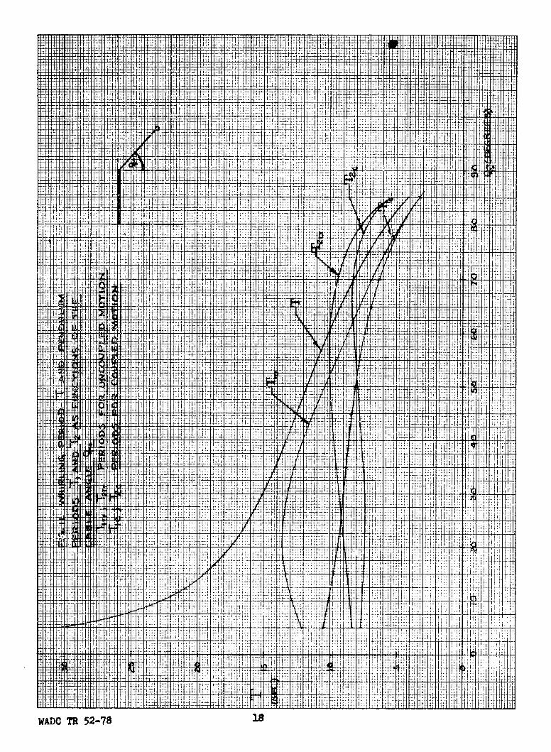
The period T,, -V,= is plotted versus the whirling frequency inFig. ll,where it is rarked Ti.
The period of the uncoupled outward-inward pendulum motion reachesabout 90% of the whirling period.
b. Fore and aft oscillations: This type of oscillation occursin the tangential plane. The restoring forces are again given by thecomponents of forces related to the gravitational and the centrifugal forces.
WADC TR 52-78 17
i tjT---- ý1
--- --- 4f
tit 211 11
7 If f: I if 4-i+ l
# #11.4 k-44T-4W#1,JM -M 7ý _t _V11 441 1 _P 1 411, t-t4 '--t i 1-i I I-,
r 1- :11I till lt-- fff T141
lj* 4ý
I lit.
'litIi I fit f
Mtt7r
T41 --.-I H ff i -t:, if- I till
:4 -f 1 1 1 if
111 t tt 1 ql rL: -. tit -- i-
liltlip lit!
'I 'll Jill : tIl I
I- JH!t
ý,l ýj
if
f tit _+ Li
1ý44
41 17fl, 4,1, T, It
7 7 ITT:
+;
tt
j Tf
ý41
lit, A ,1tt I : T f, 1 it
it Vi it'll,'4
fl, ift: fi i Lt
it t
Fl V-4 0 !4
Ft il--t' IJE t! it -ý' i . ' '+ 4-ý`t fr 1
4 i-ii t 1_ 1
p" t4 h±r
414ýIT
EEHI
A till ti :tl
tit lk i
;lit
HIT
L ý 4
it
t -41 17' 417 lit!
l' T4 11'o tit
HTE 14-H,
'jj 'Il i N ' I i i 'I : "
- i 11 ill il c i if it
jýj Lit i-t"t 1 f
if, I Ali
4
tit 1-; fLi
It -Vi
f t I
j H: 4t 1, il:t 5 -:ý4:
lit .1-4; r 1
4
::1 r
it 1,
till7 ti 11
till;H:
4 lilt
Atil"TT
TI it I 'i it '. I:;; I
11 t ý11 J! h I'T'
JtNt t ý'J H4fit,
; L
it
+ H it
i4
1:1i
-11 t -41' :' i ; , i 1
iLi 'N itJT .ý..
1., .' .' , . 'T _ ',!Ill lilt
t Till lil
f i ll f 4 1 !tit Tit I , '111
it
I i t
7T
if
--- It i 74
f
if
H ii tit I tf it
ITT
4 ýL . 1 4 t' it fit if
it
WADC TR 52-78 is
Coriolis forces do not enter the investigation of the uncoupledoscillations, since these are typical coupling forces.
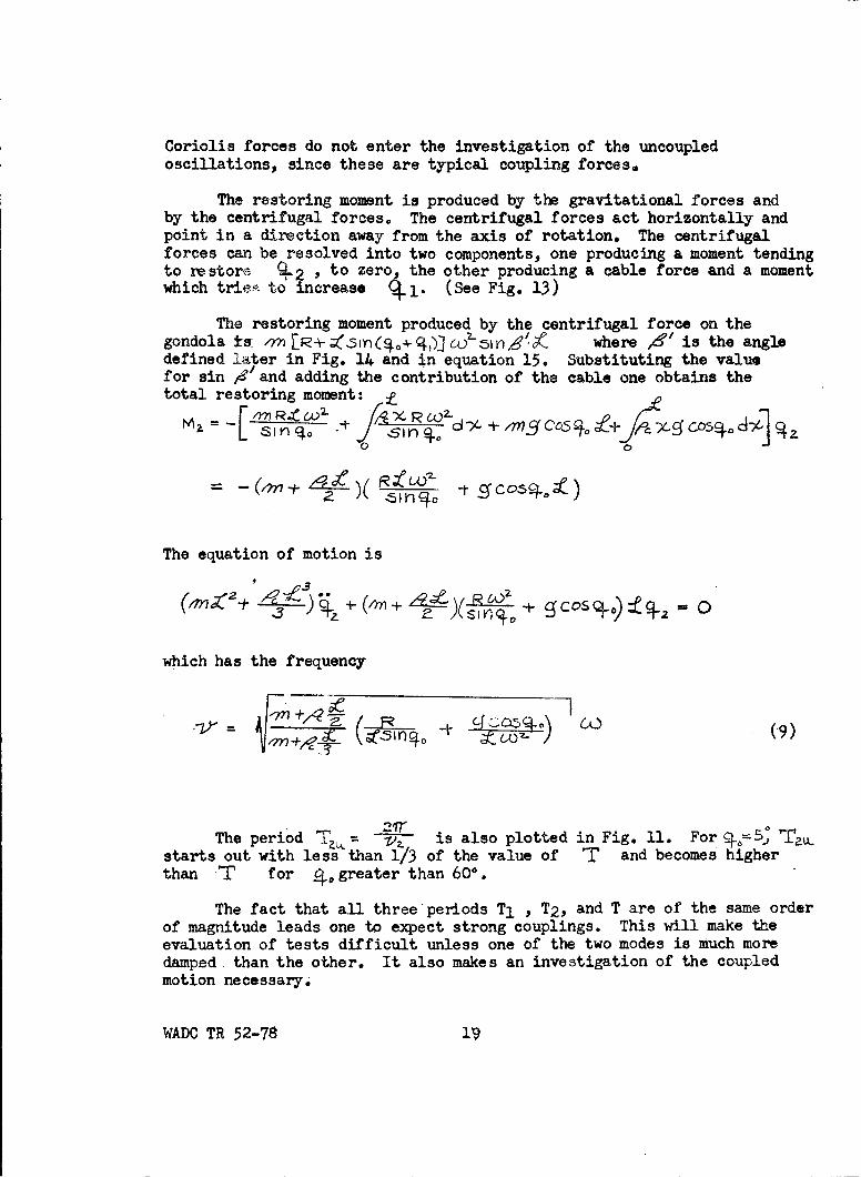
The restoring moment is produced by the gravitational forces andby the centrifugal forces. The centrifugal forces act horizontally andpoint in a direction away from the axis of rotation. The centrifugalforces can be resolved into two components, one producing a moment tendingto restore q2 , to zero, the other producing a cable force and a momentwhich trie,• to increase . 1. (See Fig. 13)
The restoring moment produced by the centrifugal force on thegondola so where /&/ is the angledefined later in Fig. 14 and in equation 15. Substituting the valuefor sin 4? and adding the contribution of the cable one obtains thetotal restoring moment:
= ~ Rt-i coo~ tJ>cicoX.Rd-6L240
=51 -r)'40
The equation of motion is
.3
which has the frequency
C-. 9
The period- V7 is also plotted in Fig. 11. For%, •5 'T]starts out with less than 1/3 of the value of T and becomes higherthan T for 4,greater than 60.
The fact that all three periods T1 , T2 , and T are of the same orderof magnitude leads one to expect strong couplings. This will make theevaluation of tests difficult unless one of the two modes is much moredamped than the other. It also makes an investigation of the coupledmotion necessary.
WADC TR 52-78 19
Derivation of the Equations of Coupled Motion
The investigation of the stability of the steady state motionsof the gondola is the main purpose of the present report. This willbe done on the basis of the theory of vibrations developed by Lagrange.
The degrees of freedom considered are described by the coordinates
•i,42,2+33,q4,, which have been introduced before. This means that therolling motions of the gondola and the torsional and translationalmotion of the cable in itself, which do not affect the position of the
cable ends, are neglected.
In order to eliminate the internal forces produced by the cable,the equations of motion will be used in the Lagrangian form. Using thesymbol H for the kinetic energy and Ql, Q2, Q3, Q4 for the generalizedforces belonging to the degrees of freedom j, 4 2 ,•3YC4 4 , respectively,the Lagrangian equation of motion can be written:
daH a H =(O
'ý7 'Dd H 1-4 (10)
at~ ;ýq Q
The kinetic-energy will be calculated in the rotating system.Consequently the centrifugal force and the Coriolis force will be includedin the generalized forces Qn.
The kinetic energy H can be split up into two parts, the kineticenergy Hg of the gondola and the kinetic energy Hc of the cable.
The velocity has two components each one in the direction of thecoordinates4 1 and 42" For the gondola these components are
WADe TR 52-78 20
For a mass element of the cable having a distance x from point
P the equations are:
'Vac~Y.
Consequently
H - H i-.Hr Z- ++ LT Z + .
The generalized force Qn is the work done by the external forcesduring a virtual displacement 9% divided by the displaceent 6 •.The external forces are the gravitational forces, the air forces, thecentrifugal forces, and the Coriolis forces, that is all forces exceptthe cable force, which is an internal force.
The direction of the gravitational force is vertically downward.The centrifugal force is in a horizontal direction outward. The Coriolisforce can be written in vector symbols
S= -" ?- 1.,n 6 x(12)
and may be split up into components according to the two components ofthe velocity V . Since all vectors of the form CDA 3- are perpendicularto the vector (M which is directed vertically downward, they are allcontained in a horizontal plane. The componeht acos4-oAW, points back-wards, while the component Etco4kpoints away from the axis of the tower,(See Fig. 12)
The lift force L on the gondola rolls with the gondola and hasalmost the direction of the cable (See Fig. 12). Drag and cross forcesare perpendicular to the lift.
It is assumed that the gondola is trimmed for CL - 0 and CC - 0and that it moves at minimum drag coefficient as long as the speed issteady. This means that -= o and - 0.
WADC TR 52-78 21
C
V
The gondola is shownL or C- 2 - 0.
Otherwise only secondorder terms would be
onI [-f N ad.n
L
1 =--wCo5A• Fig. 12 The external. forces acting
"on the gondola.
Subscript p means themagnitude is not shown in
Centrifugal force: - 12 (A. x x × ) full value, but in pro-
Coriolis force: -jection only.
WADC TR 52-78 2

Consequently
-L /Mn wO [R+fs- COS (')]. cos - 1,ngXsin(~i.qt.
"+ 2-OC COSc'-.c 1 COSdSi0-
or
174 WZ[±f-~. 0 9jcos(q4+q.4) - $i(ot.+9.,+ ,~~~~ S 11" s~(9,+% co(*c 1 - s ( t
+ (•CD [-) 6 ZD *-[n a +1.9 ] , - (•cos,• ( -3 )
Before the generalized force Q2 is derived, the location of thecentrifugal force on tVe gondola relative to the virtual displacement. AZwill be described. & is located in a horizontal plane and points inthe direction from the axis of rotation outward (See Fig. 12). It isresolved into three components. &ijhas the direction of the cable, 'j9isperpendicular to the cable in the direction of increasing I , andis horizontal pointing in the direction of decreasing C .
One reads from the rectangular spherical triangle P /Q Fig. 13.
Cos, PIG cosq.a cos(%.+%ý)
.Sin nG VI
When %,, approaches zero and if % 1 and ' 2 are small one obtains forý the limit value 1r/a as one would expect.
For finite values of 9o and small values of Ci4 and q2 one canassume
S4 (14)
WADC TR 52-78 23

Fig. 13 Division of the centrifugal forceinto three components.
The location of the component %z. of the centrifugal forcerelative to the cable is shown in Fig. 14 in two projections.
Sp Considering that PGII isthe projection of the cablelength in a horizontal planeone has PG" .%Sl(%±C.)Hence
R _ sn4'
for small a(/ and •Further is
Q --- I 77_ •according to equation (14).
- 170qCOS(9q. t
a. Plan view b. Tangential plane
Fig. 14 Position of the centrifugal forcerelative to the gondola.
WADC TR 52-78
Hence, when 9, is neglected in comparison to Q.,
%_1 q?_(15)
Using this result, the component 41 • of the centrifugal force/Mn I R* 5(i• n w- becomes
This force is perpendicular to PG". Similarly one obtains for thecorresponding component of the centrifugal force on a cable element
After adding the contribution of gravitation, of the Coriolis force,and of the air forces one obtains the generalized force
.- ?_ 5j (16)
This equation is not valid for %= 0, since equation (14) has beenused. The case = 0, however, is of no interest. The contribution ofthe lift force is but small and of second order and has been neglected.
The Coriolis force might be treated in the same way as the centrifugalforce. Since, however, the Coriolis force is small but of the first order,the moment which originates from it by the multiplication by sa. would besmall and of the second order. This component is therefore neglected. Thegeneralized forces Q3 and Q4 include aerodynamic moments only.
+ TV (18)
WADC TR 52-78 2
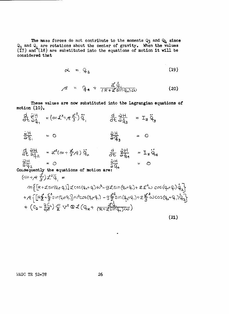
The mass forces do not contribute to the moments Q3 and Q4 sinceQ and Q, are rotations about the center of gravity. When the values(17) and (18) are substituted into the equations of motion it will beconsidered that
,(19)
44* -(20)
These values are now substituted into the Lagrangian equations ofmotion (10).
H N
Consequently the equations of motion are:
l'n {[r -iLsR(~ g.) o (.*97 c- .si n A- co's(.
t -,e ... C4,-
(21)
WADC TR 52-78 26
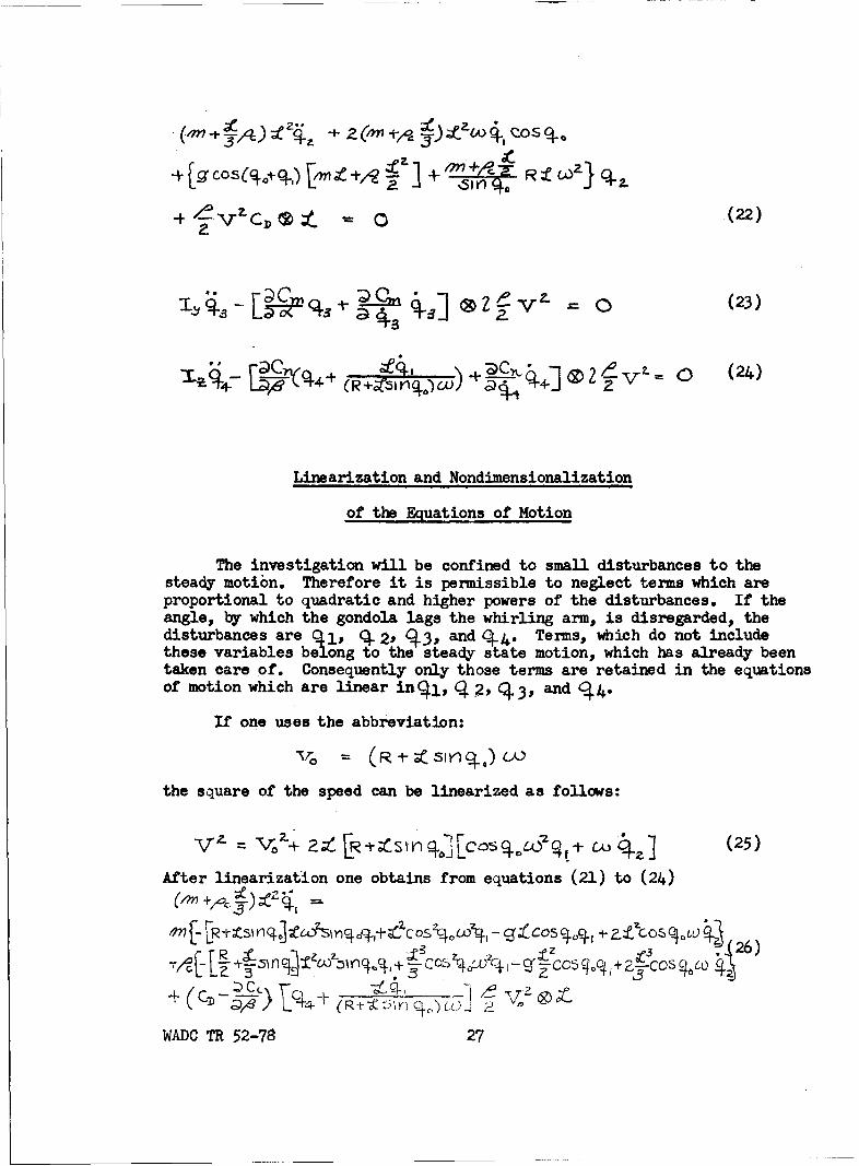
(,?n~ ~~ +z(Wi Cose~
- c-.(22)
®2i -V1 0 (23)
Linearization and Nondimensionalization
of the Equations of Motion
The investigation will be confined to small disturbances to thesteady motion. Therefore it is permissible to neglect terms which areproportional to quadratic and higher powers of the disturbances. If theangle, by which the gondola lags the whirling arm, is disregarded, thedisturbances are Q 1 , 04 2, CO, and 04j. Terms, which do not includethese variables belong to the steady state motion, which has already beentaken care of. Consequently only those terms are retained in the equationsof motion which are linear in(l,, q 2P (43 3, and (44-
If one uses the abbreviation:
the square of the speed can be linearized as follows:
%r,-i- 2y- 40 2CoStO2 l (25)
After linearization one obtains from equations (21) to (24)
+on- R Is , z g 1 V-
" ", L- 44 t (n • ,,+ •_ Icos C4bLo 4-, 26
WADC TR 52-78 27
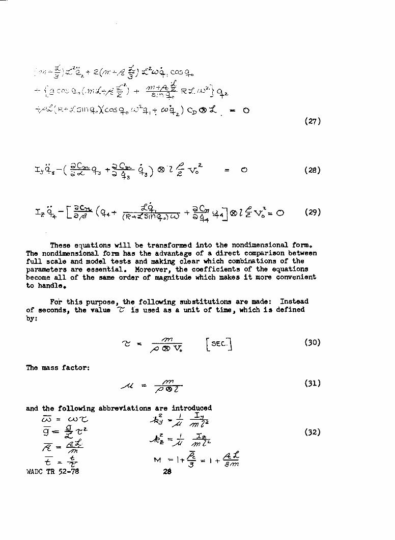
60 C0
(27)
4),W0 )vo = 0 (28)
1. 4 , • (944- •'-+ •~q,, 2) • , ,• V,, 0 (29)
These equations will be transformed into the nondimensional form.The nondimensional form has the advantage of a direct comparison betweenfull scale and model tests and making clear which combinations of theparameters are essential. Moreover, the coefficients of the equationsbecome all of the same order of magnitude which makes it more convenientto handle.
For this purpose, the following substitutions are made: Insteadof seconds, the value Z' is used as a unit of time, which is definedby:
MC-/ V0 VEc (30)
The mass factor:
(31)
and the following abbreviations are introduced
-22t (32)
5-7WADC TR 52-78 26
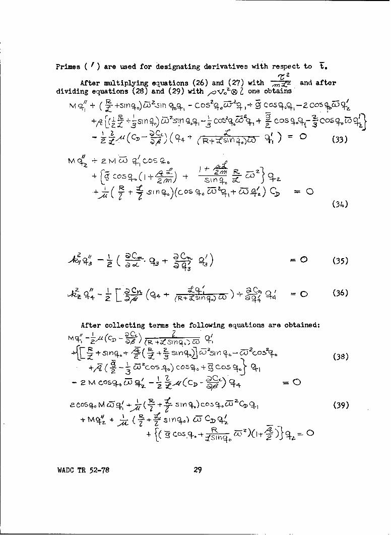
Primes ( f) are used for designating derivatives with respect to t.
After multiplying equations (26) and (27) with • and afterdividing equations (28) and (29) with one obtains
M -, •Z •S)'- • - Co c ,&X4•% -••c~o- 05CoC qo•9-+-rnq~) Xconq•- %• % + cos 9o~-
+ +5hA O& nA, ', -
(34)
T CO COS,, C-ý ro,./
:E" (" + (R:D ot O >--t-W--4 c = -C (336)
After collecting terms the following equations are obtained:
-- (ý + (Mc W q CO 14
(34)
G) C, (35)
((4 (+;S (36)
I C
AAD7 S1 52-78 2 1

44- .-0 (40)
I Q~n CYN q4 C (41)
The solution of the equations is assumed in the formt
A- - (42)
If the solution is not identically zero, which would represent thecase of undisturbed motion, which is of no interest here, the determinantof the system of equations (38) to (41) must vanish. This determinanthas the form
CO)'+ bo"-l) + CL't 2--1)Cq
(43) bZ.i . -t- kY C .21)2" bZ Z[) Q2 26 a .
where
c il (T)z '- 1',
b 2p.i -2 e, 7 00 .
c-c77 30 (4)
!,ADO TR 52-78 30
5 1 Y) Z5C
C.3 3
.b,.L = -½ )LbL33 -• .•
b4 a1 a le (• * t S• hq.4 (44)
( 4 4
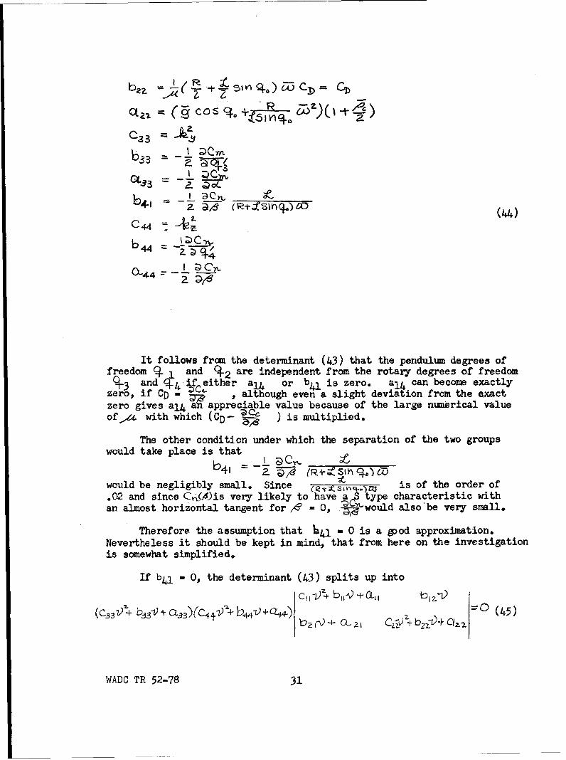
It follows from the determinant (43) that the pendulum degrees offreedom 9 ] and C2 are independent from the rotary degrees of freedom
3 and • if either al4 or b~l is zero. a 1 4 can become exactlyzero, if CD - , although even a slight deviation from the exactzero gives a,141? appreciable value because of the large numerical valueof,,& with which (CD- ) is multiplied.
The other condition under which the separation of the two groupswould take place is that
would be negligibly small. Since (ets~v~o- is of the order of.02 and since C1ý(A)is very likely to have a type characteristic withan almost horizontal tangent for /6 -0, 0-would alsobe very small.
Therefore the assumption that mi w 0 is a good approximation.Nevertheless it should be kept in mind, that from here on the investigationis somewhat simplified.
If b-l - 6, the determinant (43) splits up into
-o (45)
WADC TR 52-78 31

Instead of an eigth degree polynominal, two quadratic and onequartic equation has to be investigated.
Stability of the Coupled Pendulum Degrees of Freedom
The quartic determining the stability of the pendulum degrees offreedom •i and q 2 can be written:
A 4 -) + A.3 -03 +z-- A,'- + A C) (46)
Here, the following abbreviations are used:
A4 - Cil C2 2
A3 - C1l b2 2 + C2 2 bl1
A2 - CII a2 2 + bll b22 + C2 2 all - b2l b12 (47)
A, - bll a2 2 + b2 2 all - b1 2 a2 1
Ao - all a2 2
The conditions for stability are
A-4> 0; A3 > 0; A2>- 0; AI 0; AO ý; 0
A, A, AA 3 -A2-A 4 - A0 . 3 >0
If the Routhian discriminant, R, is going to be chosen as a measureof stability, the coefficient A4 of the frequency polynomial must be madeequal to one. This means that each coefficient A is divided by A4 = M2 .If we retain the coefficients as being given by equations (47), thediscriminant Routhian has to be divided by M6. One has
R A_ z E fA 3 - A I ZM•, - •i, AIAz~-A,4 -- , A 2 -7
Substituting the values from equations (47) and (44) and consideringthat bll - 0 one obtains:
AA.3-A,A 4 CjM#(o,1 ± oC+Zi 4M 6CosZ - C + ?M F)k'C OS CID)
=CbM jtZ~ CZ 2M CA)CO$2q
Aj(AzA3-A,A 4/) = CL MI(Can+ 2 rA C CO$N')(Ck2 *aM V3 COSc 0-)
WADC TR 52-78 32

A0---- = cMiI6"dN1Cosoocel+,az ,I•zc~~P.A CL I. a2.7 M?-C
- ~Cii ~z2MC cs -- 4 M CU 00.
P =~§ 2c",{~± ~ ~ M~5 cs~
The values of aLand a22 are also substituted according to equations(44). The abbreviation
N =A - C+M (48)
.3
is used. It is
• R
Hence_ _•_ .•os~af •_ • s _+•
After substituting the nondimensional values . and (ýo by the originalvalues one obtains
R a C,1 C &Lq. Ir4 + jn fai l= L~ COS3o+{(49)
Since 0- ° it is obvious that R- can never become negative.Consequently the only possibility of instability is that one ofthe coefficients Amay become negative. Numerical calculations willshow, however, that this is not the case. Consequently no dynamicinstabilities are to be expected.
The result of a numerical investigation of the stability of thesystem with a single torsion free cable is reproduced in Table III. Thecalculations are based on the data of Table I. The calculations are madefor the fully loaded gondola of W - 685 lbs and for a cable with a weightof 5.17 lb/ft including the weight of the sheathing.
WADC TR 52-78 ý3

The Table III lists the coefficients Ao, Al, and A2 of the frequencypolynomial for the range of q- from 5* to 85". A3 and A4 have theconstant values A3 a .2326; A4 - 1.670. The drag coefficient of thegondola including part of the cable drag is assumed to be CD - 0.24.This value might actually be somewhat higher. This difference, however,would affect the stability only very slightly.
The frequency polynomial has been solved by means of the methoddeveloped by H. C. Gebelein* which is considered especially suited forcases like the present one, where the roots are located relatively closeto each other. The damping ratios ' 1 and 5 2 are extremely low, i.e.,in the order of about 10-7 and 10-3. Becausq of equation (49), however,one is sure that an inaccurate assumption or a variation of the data willnot lead to instability.
The periods Ti and T2 , which were calculated previously neglectingthe mutual couplings, are also listed in Table III. A comparison with theformer values shows that the coupling decreases the periods at all cableangles • , The cable angle, however for which the two periods are equalto each other, remains the same (52.-45.
MODEL TESTS
The theoretical investigations shown on the preceding pages had tobe made without reference to other reports since, no analytical treatmentof the same or a similar problem was known. Therefore it was desirableto verify the results by tests at least qualitatively.
Checks on the full scale equipment were out of the question becauseof required time and cost. Therefore recourse was made to tests on a1:20 scale model.
It is obvious that a dynamically similar model in an exact sensecould not be built. While, for instance, the full scale Reynolds numberof the round unsheathed cable is above the critical number, the correspondingReynolds number of the model was below the critical number.
These insufficiencies, however, were not considered serious, sincethe theory had revealed their secondary importance. The intent of themodel tests was not so much to reproduce the characteristics of the fullscale equipment as to check qualitative theoretical results similar tothe following. The frequency of the two pendulum modes is about equaland as long as the cable angle is below 70* both periods are shorter than
* H. C. Gebelein: Treatment of Fourth Degree Equations - AF Tech Rpt No. 5992.
WADC TR 52-78 34

the period of turning of the arm. All configurations going to be testedwill be stable, but the damping will be very low.
It was especially the latter result which would represent a sensitivecheck. The only instrumentation needed would be some means of recordingthe motion following a disturbance.
Dynamic Similarity
The trnamic similarity of the model was based on the length scalefactor A a 1:20 and on the requirement that the direction of theresultant of centrifugal and gravitational forces should be the same forthe model and for the full scale equipment. Since the gravitationalacceleration g is the same for model and full scale equipment, thecentrifugal acceleration had also to be the same. This means thatthe circumferential speeds had to have the ratio ?6V: I:
Masses were reduced by the factor - 1:8000. This applies tothe mass of the gondola and of the cable. The similarity of the air forcesis fulfilled automatically.
For two reasons, no effort was made to obtain similarity of themoments of inertia of the gondola. First, the moment of the inertia ofthe present gondola was not known and the data on the new gondola whichis going to be designed were not yet available. Secondly, the theoreticalinvestigations had shown that there would be very little coupling betweenthe rotational degrees of freedom and the pendulum degrees of freedomwhich are of interest here.
Model Test Equipment
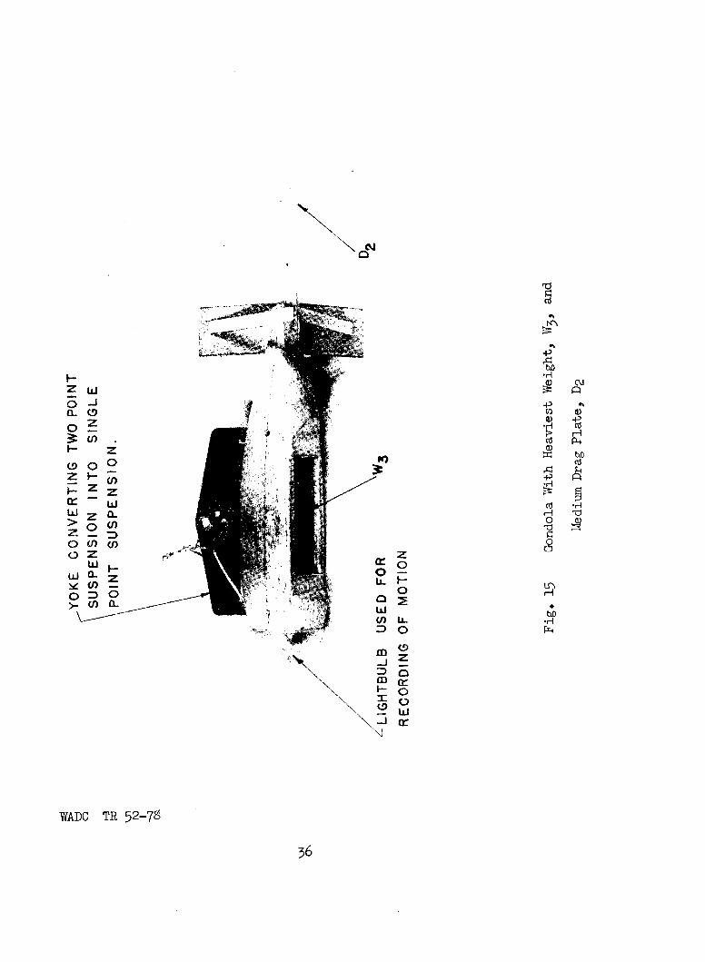
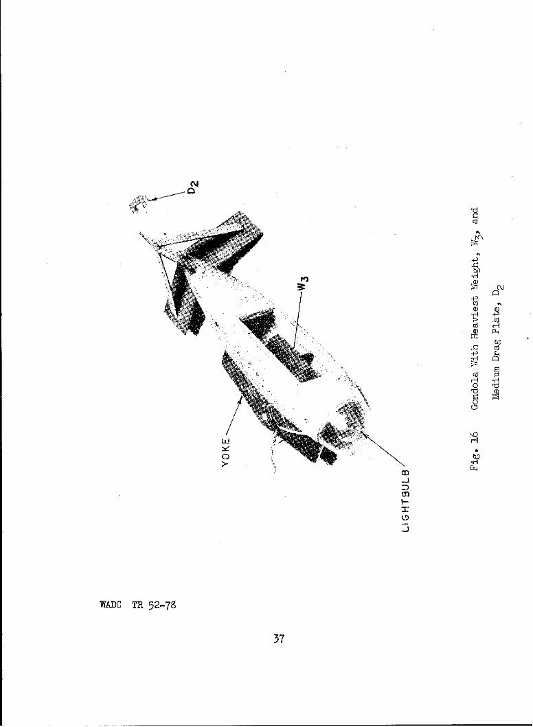
It was out of the question to build more than one gondola model.Since the full scale gondola will later on be suspended with a singlecable attached above the center of gravity, the single cable suspensionwas reproduced by the model. The dimensions of the new gondola were notyet available. Therefore the model was built in the form of the oldgondola adapted to a single point suspension as being used at El Centroby that time. The cable was attached to a yoke which connects the twoformer point of attachments (See Fig. 15 and 165.
,T!is arrangement has a large lateral area. Therefore the conditionCD - - 0 was very likely not fulfilled. Hence it was expected thattests with this model would also indicate to what degree a violation ofthe assumption CD - ' = 0 would modify the theoretical results.
WADC TR 52-78 35
>oJ0
(ti
4'
I-�3) (\J
4' .'U) 6)6) -4-'
*H �:'- H'ti P-4a,
4' �'H
cti *HH �d
H0
bflr4
-icr
N
WAUC TR 52-7S
fli
4-)
Cd
4-3
ca
WADC T 52-7
37A
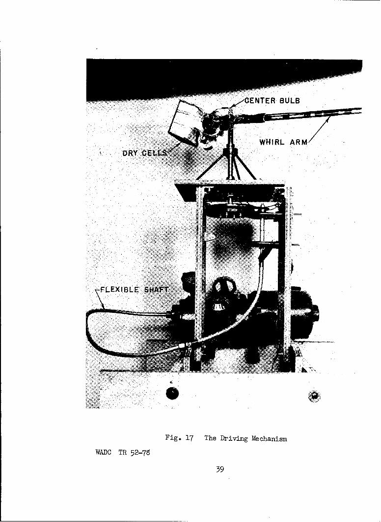
The driving mechanism consisted, during the first tests, of anelectric motor designed for high gondola speeds. At the test speeds,which were much lower, the motion was erratic. Even when a gear reductionof 11:1 was used the motion was not even enough for reliable measurement.
Therefore, the electric motor was replaced by a compressed air motor.Though this gave a much smoother drive serious fluctuations of the speedwere encountered when other tools connected with the same compressed airtank were in operation. The available pressure regulator could not copewith these pressure fluctuations. Finally an electric motor controlledby the Ward Leonard system was installed, which gave satisfactory smoothnessof the turning speed. (Fig. 17)
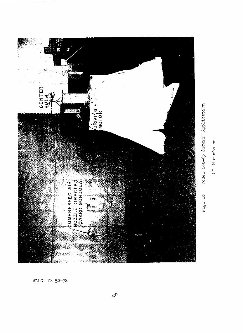
The disturbance of the motion was produced by a jet of compressedair. The jet was formed by a nozzle mounted on a tripod (Fig. 18). Asuitable direction of the nozzle was found by trial before a measurementwas made. The distance of the nozzle from the gondola path was so chosenthat the disturbance was of a reasonable magnitude.
The purpose of the tests was to obtain numerical results on theperiods and the dampings of the disturbed gondola motion. The easiestway was considered to be the taking of time exposure pictures of themotion. For this purpose, the nose of the gondola was made of transparentplastic and an electric light bulb was installed underneath of the plasticcover (See Fig. 15 and 16). Light bulbs were also mounted on the end ofthe turning arm and at the turning center (Fig. 18). The traces of thesetwo latter light bulbs helped in aligning and comparing photographs ofdifferent tests.
Two cameras of 4" x 5" size were used for recording the motion. Onecamera was located above the model tower. By means of a plumb line theoptical axis of the camera was lined up with the axis of rotation. Theview taken by this camera is shown in Fig. 20. The other camema was on atripod facing the model tower. The distance of its lens from the axis ofrotation was 29 feet, 2-1/2 inches. Its optical axis had the same heightabove the floor as the turning arm. A view taken by this camera is givenby Fig. 21.
Eighteen different test combinations of gondola weight, cable weight
and additional drag were tested, as listed in the following table.
Run No. Gondola Weight Cable No. Gondola Drag
1 wI cI D1
2 Cw 1 ,
3 W3 Cl
WADC TR 52-78 38
CENTER BULB
WHIRL ARM
DRY CELLS<
•FLEXIBLE SHAF
Fig. 17 The Driving Mechanism
WADC TR 52-78
39
70
4-3
I) U
o zi0
WADC TR 52-78
140
PROTRACTOR USEDFOR SPEED ADJUST-
Fig. 19 Model Set-Up Showing Use
WADCTR 5-78 Of' Protractor For Speed Adjustment
WADC T 52La

-Trace ofTip Bulb
-Trace ofGondola
-Model Tower
Fig. 20 View of Overhead Camera
Fig. 21 View of Ground Camera ShowingModel in Operation
•ADC BR 52-78 4 2
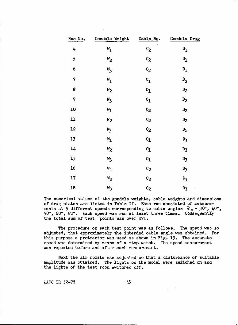
Run No. Gondola Weight Cable No. Gondola Drag
4 w C2 DW
5 W2 C2 D,
6 W3 C2 D
7 Wi C D 2
8 W2 Ci D2
9 W3 Ci D2
10 W1 C2 D2
U1 W2 C2 D2
12 W3 C2 DI
13 W, Cl D
14 W2 C1 D3
"15 W3 Cl D3
16 Wi C2 D3
17 W2 C2 D3
18 W3 C2 D3
The numerical values of the gondola weights, cable weights and dimensionsof drag plates are listed in Table II. Each run consisted of measure-ments at 5 different speeds corresponding to cable angles •o - 30, 40,50c, 60°, 80*. Each speed was run at least three times. Consequentlythe total sum of test points was over 270.
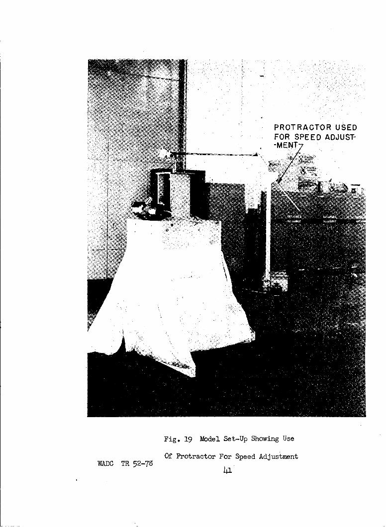
The procedure on each test point was as follows. The speed was soadjusted, that approximately the intended cable angle was obtained. Forthis purpose a protractor was used as shown in Fig. 19. The accuratespeed was determined by means of a stop watch. The speed measurementwas repeated before and after each measurement.
Next the air nozzle was adjusted so that a disturbance of suitableamplitude was obtained. The lights on the model were switched on andthe lights of the test room switched off.
WADC TR 52-78 43
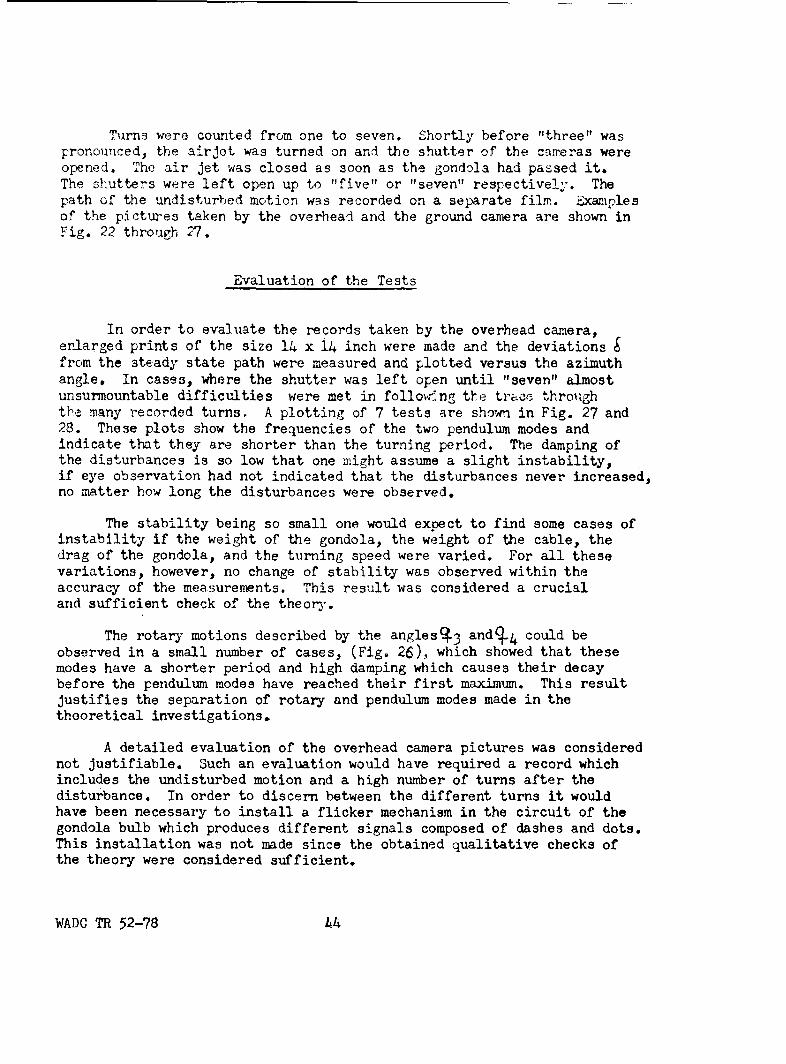
Turns were counted from one to seven. Shortly before "three" waspronounced, the air Jet was turned on and the shutter of the cameras wereopened. The air jet was closed as soon as the gondola had passed it.The shutters were left open up to "five" or "seven" respectively. Thepath of the undisturbed motion was recorded on a separate film. Examnlpesof the pictures taken by the overhead and the ground camera are shown inFig. 22 through 27.
Evaluation of the Tests
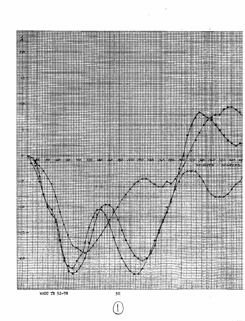
In order to evaluate the records taken by the overhead camera,enlarged prints of the size 14 x 14 inch were made and the deviationsfrom the steady state path were measured and plotted versus the azimuthangle. In cases, where the shutter was left open until "seven" almostunsurmountable difficulties were met in follow-ng t1.e tra~c• throughthe many recorded turns. A plotting of 7 tests are shown in Fig. 27 and28. These plots show the frequencies of the two pendulum modes andindicate that they are shorter than the turning period. The damping ofthe disturbances is so low that one might assume a slight instability,if eye observation had not indicated that the disturbances never increased,no matter how long the disturbances were observed.
The stability being so small one would expect to find some cases ofinstability if the weight of the gondola, the weight of the cable, thedrag of the gondola, and the turning speed were varied. For all thesevariations, however, no change of stability was observed within theaccuracy of the measurements. This result was considered a crucialand sufficient check of the theory.
The rotary motions described by the anglesc. 3 and9-4 could beobserved in a small number of cases, (Fig. 26), which showed that thesemodes have a shorter period and high damping which causes their decaybefore the pendulum modes have reached their first maximum. This resultjustifies the separation of rotary and pendulum modes made in thetheoretical investigations.
A detailed evaluation of the overhead camera pictures was considerednot justifiable. Such an evaluation would have required a record whichincludes the undisturbed motion and a high number of turns after thedisturbance. In order to discern between the different turns it wouldhave been necessary to install a flicker mechanism in the circuit of thegondola bulb which produces different signals composed of dashes and dots.This installation was not made since the obtained qualitative checks ofthe theory were considered sufficient.
WADC TR 52-78 h4

Fig. 22 Record Taken by the Overhead Camera
Fig. 23 Record Taken by the Overhead Camera o
WADC TR 52-78 45
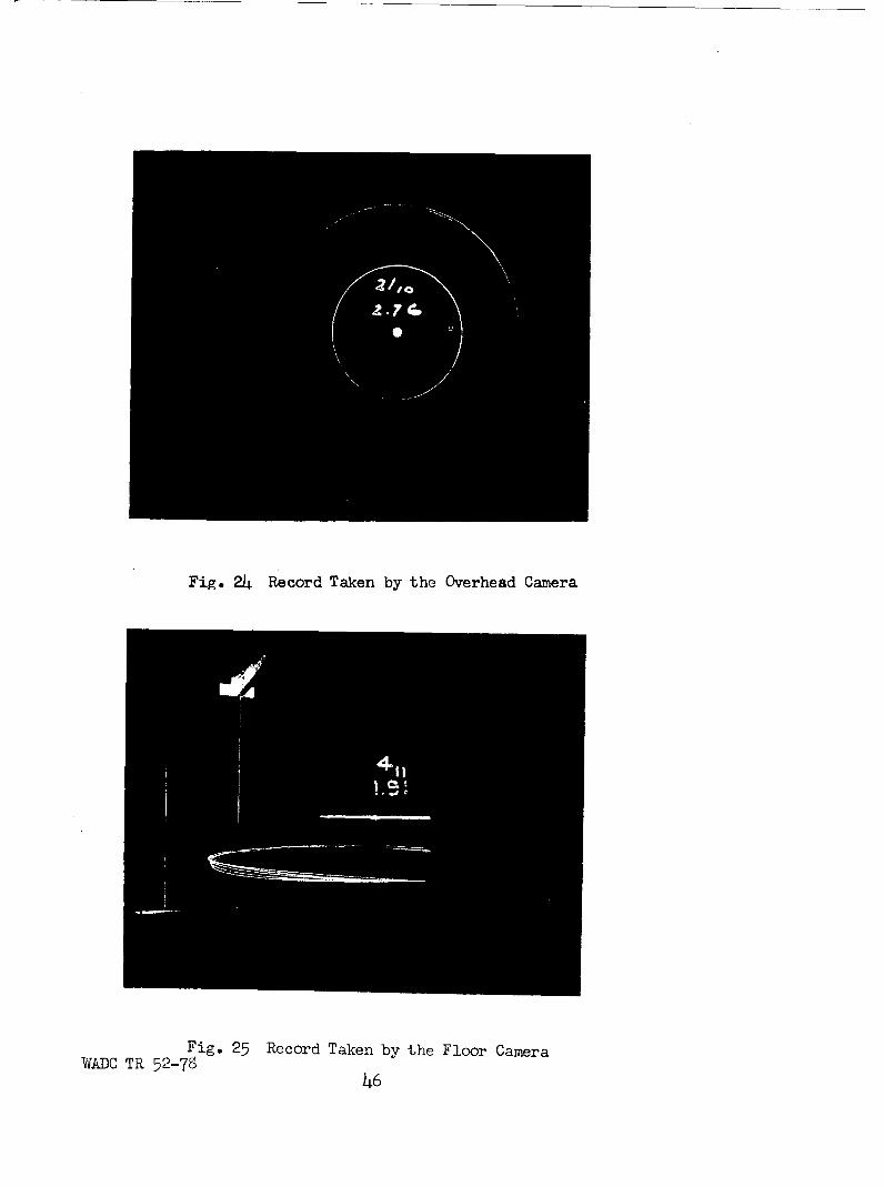
Fig. 24 Record Taken by the Overhead Camera
Fig. 25 Record Taken by the Floor CameraWADC TR 52-78
46

Fig. 26 Record Taken by the Floor Camera
WADC TR 52-7847

Explanation of the Observed Instability
Since the instability observed on the full scale equipment couldneither be reproduced by the theory for a single point suspension nor bythe corresponding model tests, the reason for the instability must belooked for in the difference between the single cable and the double cablesuspension. This is the more obvious because the instability at 50 mphdid not develop on the full scale equipment any more after the doublecable suspension had been replaced by a single cable suspension. Froman academic standpoint, an exact proof of this statement would be ofinterest.
A numerical investigation of this instability, however, meets thepreviously mentioned difficulties caused by the lack of the necessarydata on initial twist and friction between the sheathing units. Sincethe Equipment Laboratory was not interested in such an investigation, itwas not undertaken.
Conclusions and Recommendations
Based on the agreement between theory and tests, the followingconclusions are drawn:
1. Regardless what the weight and drag of the gondola and of thecable might be, regardless of the length of the whirl arm and of thecable, and regardless of the whirling speed, the pystem is always stableif a one point suspension is used and if CD - 11 0, i.e. if thedrag is higher or equal to the slope of the cross force coefficientplotted versus angle of yaw.
2. A violation of this condition mentioned in point 1 seems tohave a minor effect on the stability.
3. The observed instability was very likely caused by irregularitiesin the mounting of cable sheathing and by mutual interference betweenthe aerodynamic forces on the two cable sheathings.
4. Because of the observed instability and because of thedifficulties to be ex~pected in a theoretical or experimental investi-gation of the double point suspension, a single point suspension isrecommended.
5. From a stability standpoint an unsheathed cable of circularcross-section is the safest. Since, however, the high drag of such acable would prevent the system reaching the required circumferentialspeed of 500 mph a sheathing shuld be applied, which is flutter safe and
WADC TR 52-78 48
has, under operational conditions, a torsional fre:luency high enoughnot to couple with the yawing motion of the gondola. This means themass center of a unit length of cable and sheathing should be a fewpercent of the sheathing chord in front of the center of pres;ure indof the elastic axis.
6. The new gondola should have such a form that its slope of crossforce coefficient versus angle of yaw is as small as possible. Thismeans that the lateral projections of all surfaces, which produce crossforces, should be kept to a minimum. If there would be no drag restrictionsa sphere would be the ideal form
WADC TR 52-78 49
........... .......................... ...... .. ... ..
......................................
........... .5......0 . ......... .. .. .... .... .0.. ....
* -! t HH C... ..
11-7
Ti4-7_
T-I
+~ Etý
4~~~~- - '4+tw~tt~ F
WADC TR 52-78 51
-. i
++
+4+- - 4
4 2 ....... T
4+i -4-
TB3LES
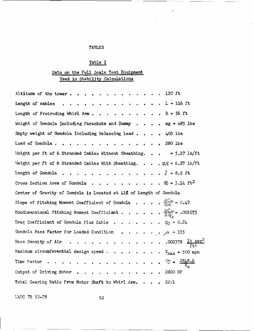
Table I
Data on the Full Scale Test Equipment
Used in Stability Calculations
Altitude of the tower. . . ... . . . 120 ft
Length of cables ......... . . L=116 ft
Length of Protruding Whirl Arm .. ........ R - 56 ft
Weight of Gondola Including Parachute and Dummy . . . . mg 685 lbs
Emtpty weight of Gondola Including Balancing Lead . ... 405 lbs
Load of Gondola. . . . . . . . . . . i . 280lbs
Wleight per ft of 6 Stranded Cables Without Sheathing . = 5.17 lb/ft
W.eight per ft of 6 Stranded Cables With Sheathing . . .. = 6.27 lb/ft
Length of Gondola . . . . . . . . . ... . I = 8.5 ft
Cross Section Area of Gondola . .............. . ® 3.14 ft 2
Center of Gravity of Gondola is Located at 41% of Length of Gondola
Slope of Pitching Moment Coefficient of Gondola . . . .
Nondimensional Pitching Moment Coefficient . . . . . . .001075
Drag Coefficient of Gondola Plus Cable . . . . . . . CD = 0.24
Gondola Mass Factor for Loaded Condition 44 .= • = 335
Mass Density of Air . .... ..... ... 002378 lb sec 2
ft4
Maximum circumferential design speed . . . . . . . .= 500 mp
Time Factor . . . . . . . . . . . . .. 2848.6V0
Output of Driving Motor ........... 2800 HP
Total Gearing Ratio From Motor Shaft to Whirl Arm . ... 22:1
WADC TR 52-78 52
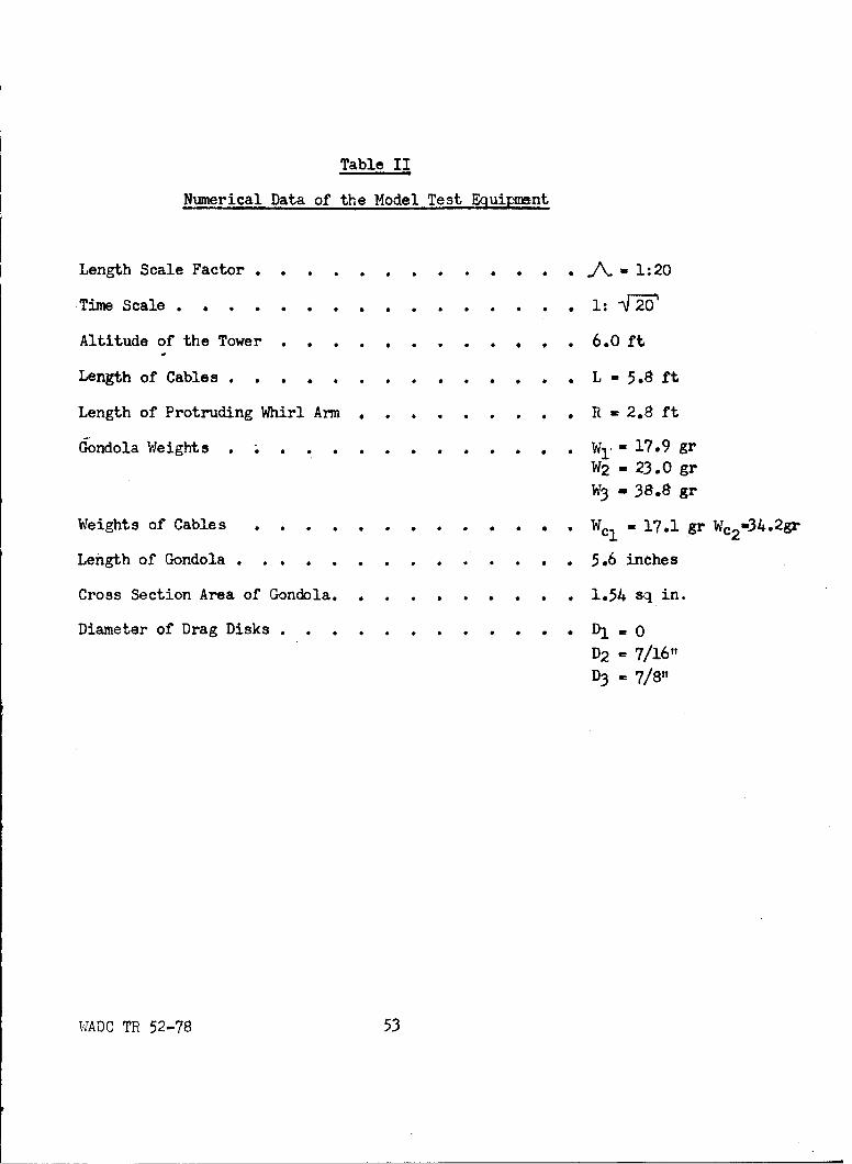
Table II
Numerical Data of the Model Test Equipment
Length Scale Factor ............. - 1:20
'Time Scale . . . . . . . . . . . . . . . . 1:
Altitude of the Tower . . . .. .. . . . . . . 6.0 ft
Length of Cables . . . . . . . . . . . .. L - 5.8 ft
Length of Protruding Whirl Arm . . . . . . . . . R - 2.8 ft
Gondola Weights . .. . . . . . . . . . . W,=17.9 grW2 = 23.0 gr
W3 - 38.8 gr
Weights of Cables . . . . . . . . . . . . . Wcl - 17.1 gr Wc2-34.2gr
Length of Gondola . . . . . . . ..... . 5.6 inches
Cross Section Area of Gondola. . ....... . 1.54 sq in.
Diameter of Drag Disks . . . . . . .. . DD2 - 7/16"
D3 - 7/8"
WTADC TR 52-78 53

.,4 H H H H H4 HA ri H H HA H- H- H- H-
'. ( D H '30 H C- --I r- in() f.0 -r N C, .cr\ N4 .4i -i' rCA (V (.1 ( r H C) C
Hd '. ' 0 '0) '0 CI0 '0 ', 10 10 10 0) 0) C 0) 0E 4 H - r- H H- H- H- H4 q -4 t-4 r 1 H1 r-- H4 H- H
0 0 )4'\ r~ A4'3 0.~ - .) ( 4 (n -,t -,t. -.-t c c' I ( N H H C) t4"\ N-\ ( (N I
Lr .N .m C, 0i c* v0) al) t 1
' (V!
4-)
r t- . O a\ a. 0 0 0'" CON G- ' oN HN C'" N )
I -0 0 m 9, 9z w 9A 9t L9 w o N 9n to 0 9.* 0 UN C' 0'D 0ý C'o in; 0; C z CZ CO CO C; 00
H
Cd9 9
O- ' c0 N N CO CO4 CO4 COj C'N C' ' "
L'\ N, C O C O C . v 0 v C O C vl
r I
0'COL o
Nl to Ac y\ cv H '0 .4, No \0 ( I -i CN L\E-a)H 0 '0 0 0r &
4-' Hl cv .4 )H j-t r , C-- H, Hq
H H- - - -I rj r -H H H cvI cv r-4 .44 H' ' c~ vH x
WA -4 TV 52..to78