Embed Size (px)
Citation preview
49-64
49
The Mining-Geology-Petroleum Engineering BulletinUDC: 622.2DOI: 10.17794/rgn.2020.1.5
Original scientific paper
Corresponding author: Wael [email protected]
Stability assessment of underground openings using different rock support systems
Wael R. Elrawy1; Gamal S. Abdelhaffez1, 2; Hussein A. Saleem1, 2
1 Mining Engineering, Faculty of Engineering, University of Assiut, Egypt, 71516, https://orcid.org/0000-0001-8133-78172 Mining Engineering, Faculty of Engineering, King Abdulaziz University, Jeddah, KSA
AbstractRock support systems have become widely dominant components in underground hard rock mines. They are used to maintain the stability of underground openings and reinforce disturbed rock masses after creating an excavation or start-ing mining activity. Thus, the objective of this study is to examine the effect of support types on the performance stabil-ity of underground tunnels that exist in hard rock mines, in terms of deformation, the extent of failure zones and the strength of the rock mass surrounding the tunnel. This, in turn, will help in the selection of an appropriate support system that mitigates the stress-deformation conditions around the tunnel. Herein, four models have been built using the RS2D program, simulated and introduced to evaluate the behaviour of an underground tunnel with different rock support systems. The first model is simulated without any support system, whereas, rock bolts have been installed in the second model. The third model applied only shotcrete, while rock bolts and shotcrete are combined together in the fourth model. The results are presented and discussed in terms of strength factor, the extent of yielding zones and rock mass displacement/convergence. The results show that tunnel stability suffers when there is no rock support at all, while, it is significantly improved when the rock support system is installed. The optimum improvement is obtained when both shotcrete and rock bolts are employed together.
Keywords:Numerical modelling; rock support systems; performance of tunnel support; underground excavations; instability evaluation criteria.
1. Introduction
Underground excavations can stand stable for a long time without support if they are driven in a rock mass of good quality. On the other hand, an adequate support system is inevitably required if these excavations have been created in a rock mass of poor geological condi-tions (e.g. a heavily jointed rock mass). Consequently, a support system must then be installed to secure excava-tions against the potential failure of a disturbed rock mass and provide safe access for personnel and machin-ery during their life span (e.g., service life) with mini-mum costs. If the excavation is designed to last for a long-term period of time (e.g., civil tunnels, underground power stations, underground nuclear waste/oil storage facilities, etc.), then a permanent reinforcement system is eventually needed (Abdellah, 2013; Guntumadugu, 2013).
The prominent function of a rock support system in underground mines is to conserve the inherent strength of the rock mass to support itself after it has been dis-turbed by excavation. It also helps to transfer the weight
from a loose/disturbed rock mass to a solid, intact and fresh rock mass. Therefore, they act as a reinforcement element (Guntumadugu, 2013). The likelihood of an occurrence of a rockburst and seismicity increases as mining activity extends to reach greater depths below the surface. Thereby, stability concerns rise and cannot be prevented (e.g. the potential for deterioration in the stability of a rock mass and surrounding underground openings continues to increase). Hence, adopting a burst-resistant rock support system is the utmost neces-sary to minimize/control the failure of underground ex-cavations (Hoek et al., 1995; Kaiser and Cai, 2012). Sometimes the design of a rock support system is per-formed prior to an excavation. However, this design is still site-specific (e.g. there is no single/unique design of rock support system that could be applied for all mines).
A rock support system may be selected using empiri-cal (e.g. classifications), analytical (e.g. calculations) and/or numerical methods. The empirical methods de-pend on the statistical analysis of underground observa-tions and the rock mass classification system; which are used in the initial stage of the project when little or no detailed information is available. Sometimes, the appli-cation of rock mass classification systems in tunnelling
Abdellah, W.; Abdelhaffez, G.; Saleem, H. 50
The Mining-Geology-Petroleum Engineering Bulletin and the authors ©, 2020, pp. 49-64, DOI: 10.17794/rgn.2020.1.5
has the disadvantage of not displaying necessary infor-mation concerning rock mass behaviour, especially the weak ones. Consequently, the geological characteristics (e.g. identity) of these rock masses are lost since they are not included in the analysis. The most common empiri-cal methods used in underground mines are Lang’s method, the Farmer and Shelton method, Rock Quality Designation (RQD), and the Q-support chart. However, these methods have many limitations such as: they do not account for the effect of the opening shape, distribu-tion of mining induced-stresses around the opening, in situ stress regimes (e.g. magnitude and orientations), rock mass deformations and the location and extent of failure zones (Deere et al., 1967; Barton et al., 1974; Grimstad and Barton, 1993; Dianmin, 1994; Mu-rugamoorthy et al., 2003; Palmstrom and Broch, 2006; Gharavi and Shafiezadeh, 2008; Rafiee, 2014).
The rate of deformation and depth of yielding zones around the tunnel mainly rely on geological conditions (e.g. rock mass properties), stress state with respect to rock mass strength or quality and flow of groundwater and water pore pressure. Squeezing is a time-dependent and yielding-mate and depends on the excavation and the installed support system. For instance, a rock mass will move into the tunnel due to stress redistribution if the installation of rock support is delayed. On the other hand, squeezing continuously causes load build-up of the support system (Barla and Marco, 2008). The ana-lytical methods are only useful in the preliminary design phase. They use regression analysis (e.g. estimate rock mass strength based on the support charts) to design/se-lect an appropriate support system. However, they are not efficient enough to assess complex mine geometry in deep underground mines (e.g. as mining depth increases, highly stressed ground conditions exist and lead to rock-
bursts and seismicity occurrences) (Carter et al., 2008; Guntumadugu, 2013).
The third method, numerical modelling, is the most acceptable tool in underground mines (e.g. it can be em-ployed for any ground conditions). This method has the capability to simulate very complex mine geometry and provide a complete solution (e.g. static and dynamic) for the rock mass behaviour at any depth below the surface (Marinos, 2010; Singh et al., 2010; Yu et al., 2012). Usually, the design of a rock support system is selected based on field observations, past experience of similar cases and precedent practice gained during trial excava-tions and early mining stages in certain areas.
In this paper, the performance stability of an under-ground tunnel has been evaluated, compared and mod-elled with and without different rock support systems. The choice of the rock support system to be installed in a particular underground excavation mainly depends on the quality of the rock mass (e.g. good or bad), in situ stress conditions based on depth (e.g. highly stressed, squeezed, hydrostatic, dynamic environment, etc.), costs (e.g. support type: primary or secondary support), geom-etry of the opening (e.g. shape and size) and purpose (e.g. temporary or permanent openings). The next sec-tion presents a brief review of different rock support sys-tems that are commonly practiced in Canadian under-ground hard rock mines.
2. Review on rock support systems
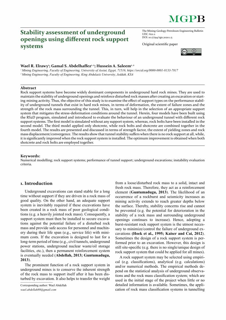
Rock support systems are divided into two main classes: external and internal support systems (see Fig-ure 1), which can be passive or active (Hutchinson and Diederichs, 1996). Passive supports do not instantane-ously reinforce rock mass after installation, but, they do
Figure 1: General classification of support system (Hutchinson and Diederichs, 1996)
51 Stability assessment of underground openings using different rock support systems
The Mining-Geology-Petroleum Engineering Bulletin and the authors ©, 2020, pp. 49-64, DOI: 10.17794/rgn.2020.1.5
reinforcement in subsequent/later stages. External sup-port systems are generally passive types. They are in-stalled around the excavation boundaries to minimize rock mass deformation and to prevent its failure/move-ment. Timber sets, steel arches, un-tensioned rock bolts/cable bolts/reinforcing bars and composite packs, wood-en cribs and fibre-reinforced shotcrete are examples of external (e.g. passive) supports. It is worthy to mention that backfill is also another common type of external, passive support used in hard rock mines (Hoek and Wood, 1983; Dianmin, 1994; Guntumadugu, 2013).
The active support immediately enhances rock mass after being installed (e.g. they directly exert induced stress on the ground) (Brady and Brown, 2004). Pre-tensioned rock bolts, cable bolts, expandable segmented concrete linings, hydraulic props and powered support are examples of active rock support systems. They are adopted when excessive ground deformations are pre-sent (e.g. rock wedge failure) (Stillborg, 1994).
Underground mines employ two main types of rock reinforcement, namely tensioned mechanically anchored rock bolts and un-tensioned grouted/friction anchored dowels (Guntumadugu, 2013; Hoek and Wood, 1983). Internal support (e.g. active support) binds/holds a rock mass together to conserve its overall stability and is pre-tensioned during the installation time.
Swellex, split sets, grouted bars and mechanical an-chored bolts are examples of an internal or active sup-port system. In Canadian underground mines, supports are described as primary or secondary support.
Primary support types are installed during the initial stages of mine development and consist of primarily me-chanical rock bolt, rebars, Swellex and Split-Set. Where-as, secondary or enhanced support types, such as modi-fied cable bolts (MCBs), lacings, straps, and shotcrete liners are installed at later stages and are intended to help the excavation sustain the stress and deformation changes due to the extraction of nearby mining blocks.
3. Case study
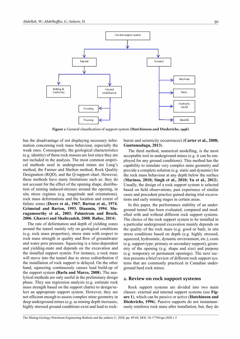
This investigation is based on an underground nickel mine situated in the Canadian Shield near Thompson city, northern Manitoba (MB), Canada (see Figure 2). The mine is the fifth-largest nickel camp in the world (Lightfoot et al., 2017). It is operated by Vale which adopted a sub-level stoping mining method with delayed backfill (e.g. cemented rockfill). The mine produces around 2500 tons/day of nickel with an average grade of 1.5%. The mine started production in 1974 even though the economic nickel deposit was discovered in 1969. As
the mine produced only nickel processing plants (e.g. smelter and mill) were set close to the mine.
3.1. Mine geology
Geologically, the mine Nickel Belt lies on the bound-ary between the Superior and Churchill Provinces of
Table 1: Average grades of constituent elements at the Canadian mine case study (Sacrison and Roberts, 2001)
Element Copper Nickel Ferro Sulphide Magnesium Oxide Chalcopyrite Pentlandite Pyrhotite RockGrade 0.1 1.7 21.1 10.2 16.5 0.30 4.90 21.7 73.1
Figure 2: The location of a Canadian nickel mine near Thompson city, in the Province of Manitoba
(Paktunc, 1984)
Figure 3: Vertical section at a Canadian mine shows a different rock mass (Paktunc, 1984)
Abdellah, W.; Abdelhaffez, G.; Saleem, H. 52
The Mining-Geology-Petroleum Engineering Bulletin and the authors ©, 2020, pp. 49-64, DOI: 10.17794/rgn.2020.1.5
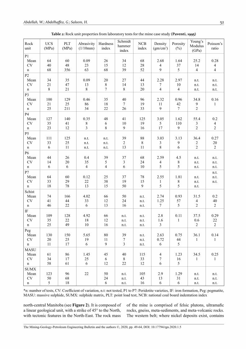
Table 2: Rock unit properties from laboratory tests for the mine case study (Paventi, 1995)
Rock unit
UCS (MPa)
PLT(MPa)
Abrasivity(1/10mm)
Hardness index
Schmidt hammer
index
NCB index
Density (gm/cm3)
Porosity (%)
Young’s Modulus
(GPa)
Poisson’s ratio
P1MeanCVn
644068
6048356
0.092363
261568
341239
682852
2.6849
1.64375
25.2144
0.2844
P2MeanCVn
34218
354721
0.09138
2087
27148
441320
2.2874
2.97104
n.t.n.t.n.t.
n.t.n.t.n.t.
P3MeanCVn
1002125
12925211
0.468634
351822
40726
961933
2.32119
0.96427
34.892
0.161
P4MeanCVn
1273523
1404112
0.3583
4868
41109
1251916
3.05517
1.621109
55.432
0.242
P5MeanCVn
111336
1252511
n.t.n.t.n.t.
n.t.n.t.n.t.
39213
88811
3.0338
3.1396
36.422
0.27202
P6MeanCVn
44146
26206
0.4354
3954
3736
682410
2.5945
4.585
n.t.n.t.n.t.
n.t.n.t.n.t.
P7MeanCVn
643318
602978
0.122213
253815
371950
78159
2.5515
1.8185
n.t.n.t.n.t.
n.t.n.t.n.t.
SchistMeanCVn
744146
1664422
4.02336
661213
502416
n.t.n.t.n.t.
2.741.25
7
0.93575
31.542
0.2402
IFMeanCVn
1093525
1282249
4.921810
661216
n.t.n.t.n.t.
n.t.n.t.n.t.
2.81.63
0.111
37.50.62
0.29222
PegMeanCVn
1302011
1502517
5.65196
80119
3973
n.t.n.t.n.t.
2.630.72
6
0.75445
36.11
0.141
MASUMeanCVn
613458
861761
1.45256
45612
40822
1153312
476
1.23165
34.51
0.251
SUMXMeanCVn
123505
966818
22 50246
n.t.n.t.n.t.
1054316
2.9136
1.29316
n.t.n.t.n.t.
n.t.n.t.n.t.
*n: number of tests, CV: Coefficient of variation, n.t: not tested, P1 to P7: Peridotite varieties, IF: iron formation, Peg: pegmatite, MASU: massive sulphide, SUMX: sulphide matrix, PLT: point load test, NCB: national coal board indentation index
north-central Manitoba (see Figure 2). It is composed of a linear geological unit, with a strike of 45° to the North, with tectonic features in the North-East. The rock mass
of the mine is comprised of felsic plutons, ultramafic rocks, gneiss, meta-sediments, and meta-volcanic rocks. The western belt; where nickel deposits exist, contains
53 Stability assessment of underground openings using different rock support systems
The Mining-Geology-Petroleum Engineering Bulletin and the authors ©, 2020, pp. 49-64, DOI: 10.17794/rgn.2020.1.5
serpentinized ultramafic (SUM) and metamorphic vol-canic rocks (Crackle and Heisel, 1981). The geology of the mine can be referred to as a brecciated ultramafic rock in a sulphide matrix (Violot, 2017; Emad, 2014). At several locations, sulphide mineralization is associ-ated with the nickel belt which precisely associates with magnesium-rich ultramafic rocks, predominantly peri-dotites. The latter, peridotites, are altered to serpentines (Donze et al., 1997). There are three types of peridotite, namely core-peridotite (e.g. which forms 50% of mine 84-ore zone with an average grade of 0.20% of nickel); mineralized-peridotite (e.g. which is disseminated with-in sulphide with an average grade of 0.5 to 3% of nickel) and barren-peridotite (e.g. which hosts brecciated ultra-mafic rock with an average grade of 0.35% of nickel). The latter, barren-peridotite, causes most of the ore dilu-tion in the produced nickel and has 33% of magnesium oxide (e.g. MgO) (McNearny and Li, 2005).
The primary constituent of sulphide is pyrhotite with a small amount of pentlandite, chalcopyrite and magnet-ite. The major rock of hanging wall is schist, while bio-tite, pyrhotite, quartz with minor traces of talc and ser-pendite is presented in footwall orebody. The mine geol-ogy is depicted below (see Figure 3) (Henderson and Lilley, 2001). The average grades, of different minerali-zation elements in this Canadian mine, are listed in Ta-ble 1 below.
3.2. Geotechnical conditions
Knowing the mine geotechnical conditions (e.g. strength properties of a rock mass; in situ stress, mining method) is necessary to evaluate the quality of a rock mass and predict temporally (when) and spatially (where) enhanced support is needed around excavations. This section describes how rock mass data was obtained, what in situ stress condition is, and what mining method was applied in the mine case study.
3.2.1. Rock mass properties
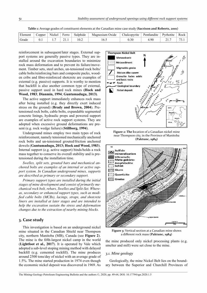
Rock unit properties were obtained using non-de-structive and destructive testing. Intact rock samples were collected, cored, and tested parallel, perpendicular, and at an angle to the foliation. Further, the results of laboratory tests were analysed using the Stratigraphic® (1987) statistical package to obtain the mean, standard deviation, the correlation and other statistical parameters (see Table 2) (Paventi, 1995).
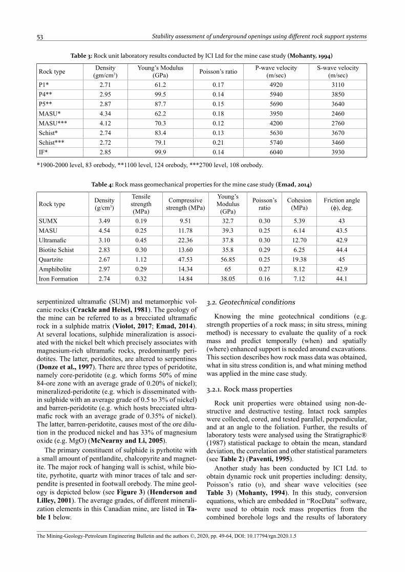
Another study has been conducted by ICI Ltd. to obtain dynamic rock unit properties including: density, Poisson’s ratio (υ), and shear wave velocities (see Table 3) (Mohanty, 1994). In this study, conversion equations, which are embedded in “RocData” software, were used to obtain rock mass properties from the combined borehole logs and the results of laboratory
Table 4: Rock mass geomechanical properties for the mine case study (Emad, 2014)
Rock type Density(g/cm3)
Tensile strength (MPa)
Compressive strength (MPa)
Young’s Modulus
(GPa)
Poisson’s ratio
Cohesion (MPa)
Friction angle (ϕ), deg.
SUMX 3.49 0.19 9.51 32.7 0.30 5.39 43MASU 4.54 0.25 11.78 39.3 0.25 6.14 43.5Ultramafic 3.10 0.45 22.36 37.8 0.30 12.70 42.9Biotite Schist 2.83 0.30 13.60 35.8 0.29 6.25 44.4Quartzite 2.67 1.12 47.53 56.85 0.25 19.38 45Amphibolite 2.97 0.29 14.34 65 0.27 8.12 42.9Iron Formation 2.74 0.32 14.84 38.05 0.16 7.12 44.1
Table 3: Rock unit laboratory results conducted by ICI Ltd for the mine case study (Mohanty, 1994)
Rock type Density(gm/cm3)
Young’s Modulus (GPa) Poisson’s ratio P-wave velocity
(m/sec)S-wave velocity
(m/sec)P1* 2.71 61.2 0.17 4920 3110P4** 2.95 99.5 0.14 5940 3850P5** 2.87 87.7 0.15 5690 3640MASU* 4.34 62.2 0.18 3950 2460MASU*** 4.12 70.3 0.12 4200 2760Schist* 2.74 83.4 0.13 5630 3670Schist*** 2.72 79.1 0.21 5740 3460IF* 2.85 99.9 0.14 6040 3930
*1900-2000 level, 83 orebody, **1100 level, 124 orebody, ***2700 level, 108 orebody.
Abdellah, W.; Abdelhaffez, G.; Saleem, H. 54
The Mining-Geology-Petroleum Engineering Bulletin and the authors ©, 2020, pp. 49-64, DOI: 10.17794/rgn.2020.1.5
tests. Consequently, these properties are used as input parameters in the numerical model as listed in Table 4 (Emad, 2014).
In the field, the strength properties of a rock mass can be evaluated using rock mass classification systems such as rock mass rating rate (RMR), rock quality designation (RQD), and the rock tunnelling quality index (Q-sys-tem). The deformation modulus of a rock mass can be measured using a borehole dilatometer. Such a device gives more realistic values that are representative of in situ stress conditions than data derived from laboratory
testing of cored specimens (Koopmans and Huges, 1984&1985; Paventi, 1995). The latter, rock moduli values derived from laboratory tests are higher than in situ stress values due to the fact that laboratory rock samples are intact and free of structure, whereas field rock incorporates geological features. A dilatometer can measure variations in the rock moduli due to change in rock lithology, the existence of joints, and weak zones. The ground of a mine that is associated with serpenti-nized ultramafic rock (SUM) experiences instability is-sues. Therefore, there are more safety concerns about excavations, the cost of ground support and ore dilution. The latter has been estimated to be $25/ton (Ashcroft, 1991) due to mucking; milling and the hoisting of addi-tional waste (Paventi, 1994).
3.2.2. In situ stresses
A tunnel has been driven into ultramafic rock at a depth of 600m below the ground surface The rock mass is disturbed after creating the excavation and ground stresses start to redistribute. Consequently, the rock mass begins yielding. The in situ stress ratio (e.g. k) was 1.67. In situ stresses were measured in the mine. Table 5 presents the in situ stress tensor values that are extracted from a study that has been done by Herget (1974).
Table 5: Field stress properties used in this analysis (Herget, 1974)
Field stress type value Orientationh, depth below surface, m 600horizontal-to-vertical stress ratio, k
1.67
σ1 (major principal stress ), MPa 30.47 Normal to the strike of orebody
σ2 (intermediate principal stress), MPa
23.75 Parallel to the strike of orebody
σ3 (minor principal stress), MPa 18.25 Verticalstress orientation, counter clockwise
-300
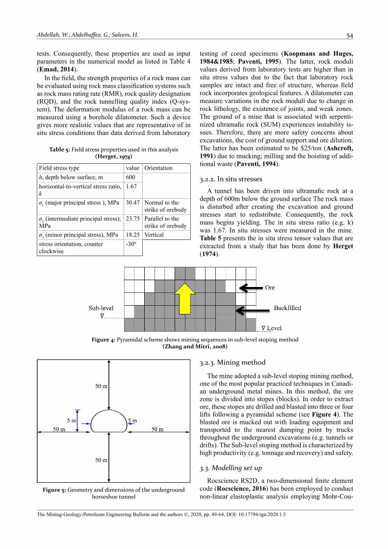
Figure 4: Pyramidal scheme shows mining sequences in sub-level stoping method (Zhang and Mitri, 2008)
Figure 5: Geometry and dimensions of the underground horseshoe tunnel
3.2.3. Mining method
The mine adopted a sub-level stoping mining method, one of the most popular practiced techniques in Canadi-an underground metal mines. In this method, the ore zone is divided into stopes (blocks). In order to extract ore, these stopes are drilled and blasted into three or four lifts following a pyramidal scheme (see Figure 4). The blasted ore is mucked out with loading equipment and transported to the nearest dumping point by trucks throughout the underground excavations (e.g. tunnels or drifts). The Sub-level stoping method is characterized by high productivity (e.g. tonnage and recovery) and safety.
3.3. Modelling set up
Rocscience RS2D, a two-dimensional finite element code (Rocscience, 2016) has been employed to conduct non-linear elastoplastic analysis employing Mohr-Cou-

55 Stability assessment of underground openings using different rock support systems
The Mining-Geology-Petroleum Engineering Bulletin and the authors ©, 2020, pp. 49-64, DOI: 10.17794/rgn.2020.1.5
lomb (M-C) failure criterion. The layout of the modelled underground tunnel is displayed (see Figure 5). The tun-nel has a horseshoe geometry and 5m by 5m dimensions and is located 600m below the ground surface. In this study, the effect of nearby mining activity on under-ground excavation was not considered. Alternatively, the interaction between nearby mining and the tunnel was beyond the scope of this study.
4. Results and discussion
Underground excavations such as haulage drifts, tun-nels, and cross-cuts are key components in underground opening networks. Such openings are used to transport workers, equipment, and blasted ore to the nearest dumping point. Therefore, their stability is crucial for the safety and profitability of a mining operation. In this study, a series of non-linear elastoplastic finite element models have been constructed using rock-soil, RS2D software. A tunnel of 5m by 5m is driven in the ultra-mafic rock mass, a typical geological formation in the Canadian Shield. The stability of the underground tunnel has been evaluated using different failure evaluation cri-teria, namely the rock mass strength factor, the extent of failure zones and rock mass deformation. The effect of the mining operations on the tunnel has not been consid-ered in this analysis. Moreover, rock bolts are the typi-cally practiced support system in the mine. The next sec-tion discusses the results of this numerical analysis with different evaluation criteria.
4.1. Rock mass strength factor
The rock strength factor is defined as the ratio of rock mass strength to induced stress. It can be described math-ematically as given in Equation 1 (Abdellah, 2017):
(1)
The rock mass strength is calculated based on the in-put rock mass properties (e.g. for Mohr-Coulomb crite-
rion, the required input strength properties of a rock mass are: cohesion, friction angle and tensile strength). While, the induced stresses are determined by the elastic stress distribution computed from the boundary element analysis (e.g. all three principal stresses (σ1, σ2 and σ3) are used in the calculation of strength factor). If the strength factor is greater than 1, this indicates that the rock mass strength is greater than the induced stress (e.g. stable conditions). On the other hand, if the strength fac-tor is less than 1, this indicates that the induced stress in the rock mass exceeds its strength (e.g. the rock mass would fail if a plasticity analysis were carried out).
4.1.1. Case I (No support system)
Figure 6 depicts the strength of the rock mass after creating a tunnel opening. The contours show that the strength factor around the opening boundary is less than 1 (e.g. SF= 0.86) around the roof, floor and walls of the tunnel (see Figure 6). This indicates unstable/unsatis-factory conditions of the tunnel opening. The rock mass would fail (e.g. see failure zones around the tunnel open-ing presented in section: 4.2).
4.1.2. Case II (installation of rockbolts)
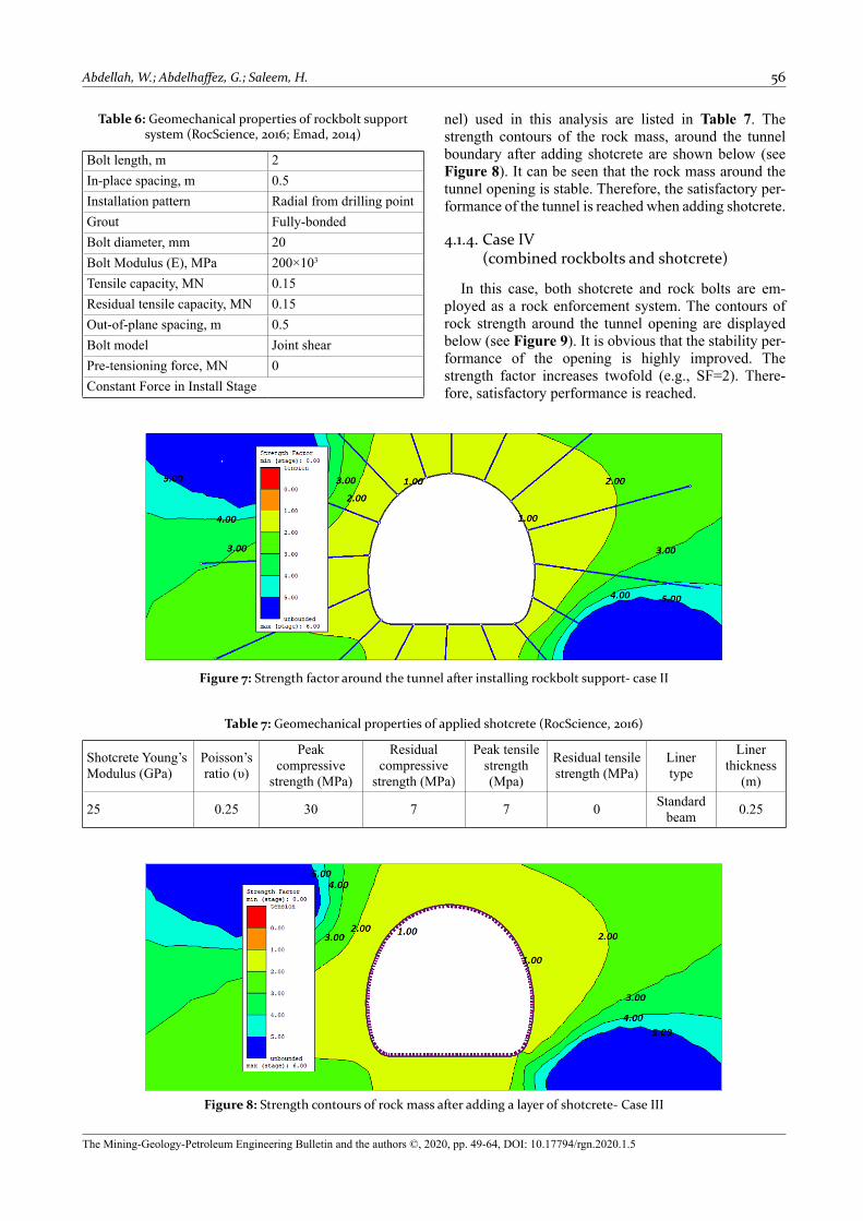
Table 6 lists the geomechanical properties of rock bolts that have been applied in this analysis. Figure 7 displays the strength contours of the rock mass, after in-stalling rock bolts, around the boundary of the tunnel. It is clear that the strength of the rock mass around the tun-nel boundary equals 1 (e.g., SF =1). Thus, this indicates the satisfactory performance of the tunnel (see Figure 7).
4.1.3. Case III (Adding a layer of only shotcrete)
Shotcrete is usually employed in Canadian under-ground mines. It comprises a base mix content with 20% of cementitious material, 15–20% coarse aggregate and a sand content that lies between 60 and 65% of the total aggregate weight. The geomechanical properties of shotcrete (e.g., installed inside the boundary of the tun-
Figure 6: Strength factor contours around tunnel opening- case I
Abdellah, W.; Abdelhaffez, G.; Saleem, H. 56
The Mining-Geology-Petroleum Engineering Bulletin and the authors ©, 2020, pp. 49-64, DOI: 10.17794/rgn.2020.1.5
Table 6: Geomechanical properties of rockbolt support system (RocScience, 2016; Emad, 2014)
Bolt length, m 2In-place spacing, m 0.5Installation pattern Radial from drilling pointGrout Fully-bondedBolt diameter, mm 20Bolt Modulus (E), MPa 200×103
Tensile capacity, MN 0.15Residual tensile capacity, MN 0.15Out-of-plane spacing, m 0.5Bolt model Joint shearPre-tensioning force, MN 0Constant Force in Install Stage
Table 7: Geomechanical properties of applied shotcrete (RocScience, 2016)
Shotcrete Young’s Modulus (GPa)
Poisson’s ratio (υ)
Peak compressive
strength (MPa)
Residual compressive
strength (MPa)
Peak tensile strength(Mpa)
Residual tensile strength (MPa)
Linertype
Liner thickness
(m)
25 0.25 30 7 7 0 Standard beam 0.25
Figure 8: Strength contours of rock mass after adding a layer of shotcrete- Case III
Figure 7: Strength factor around the tunnel after installing rockbolt support- case II
nel) used in this analysis are listed in Table 7. The strength contours of the rock mass, around the tunnel boundary after adding shotcrete are shown below (see Figure 8). It can be seen that the rock mass around the tunnel opening is stable. Therefore, the satisfactory per-formance of the tunnel is reached when adding shotcrete.
4.1.4. Case IV (combined rockbolts and shotcrete)
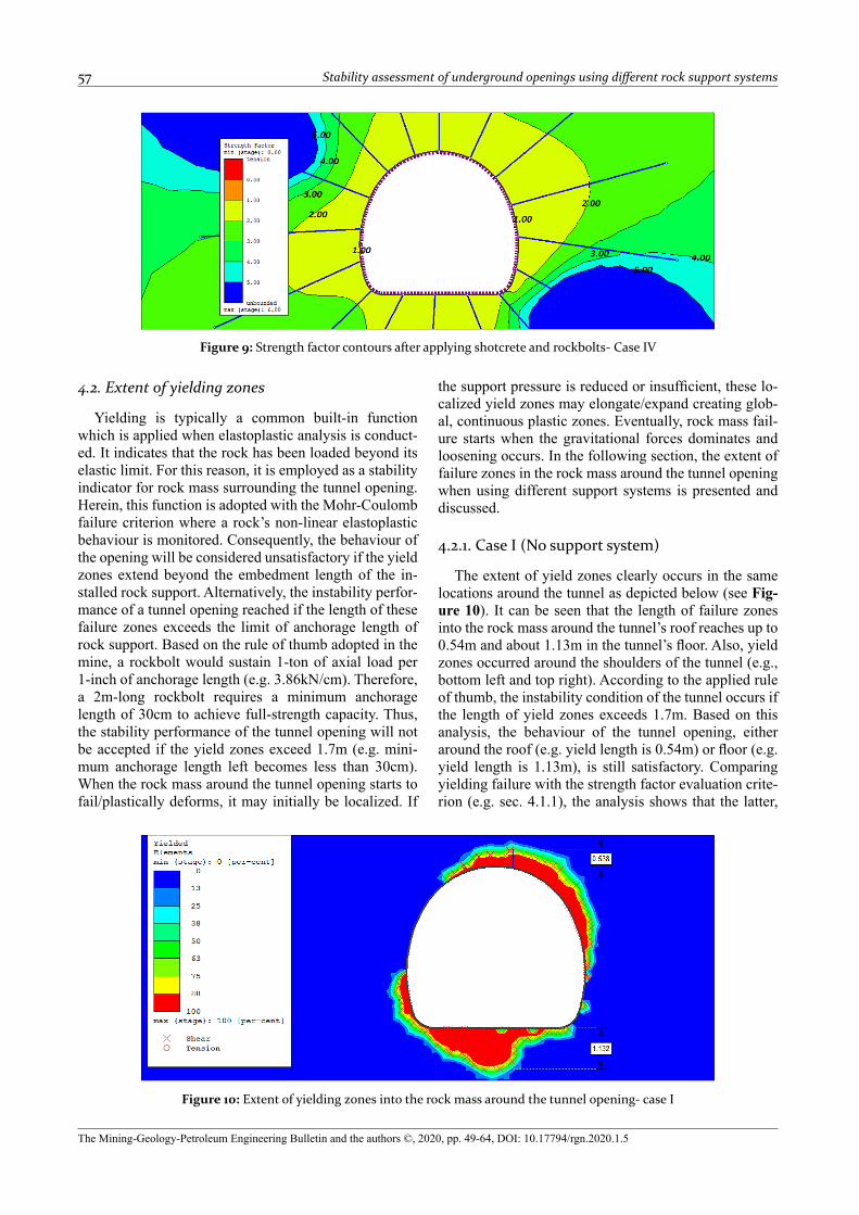
In this case, both shotcrete and rock bolts are em-ployed as a rock enforcement system. The contours of rock strength around the tunnel opening are displayed below (see Figure 9). It is obvious that the stability per-formance of the opening is highly improved. The strength factor increases twofold (e.g., SF=2). There-fore, satisfactory performance is reached.
57 Stability assessment of underground openings using different rock support systems
The Mining-Geology-Petroleum Engineering Bulletin and the authors ©, 2020, pp. 49-64, DOI: 10.17794/rgn.2020.1.5
4.2. Extent of yielding zones
Yielding is typically a common built-in function which is applied when elastoplastic analysis is conduct-ed. It indicates that the rock has been loaded beyond its elastic limit. For this reason, it is employed as a stability indicator for rock mass surrounding the tunnel opening. Herein, this function is adopted with the Mohr-Coulomb failure criterion where a rock’s non-linear elastoplastic behaviour is monitored. Consequently, the behaviour of the opening will be considered unsatisfactory if the yield zones extend beyond the embedment length of the in-stalled rock support. Alternatively, the instability perfor-mance of a tunnel opening reached if the length of these failure zones exceeds the limit of anchorage length of rock support. Based on the rule of thumb adopted in the mine, a rockbolt would sustain 1-ton of axial load per 1-inch of anchorage length (e.g. 3.86kN/cm). Therefore, a 2m-long rockbolt requires a minimum anchorage length of 30cm to achieve full-strength capacity. Thus, the stability performance of the tunnel opening will not be accepted if the yield zones exceed 1.7m (e.g. mini-mum anchorage length left becomes less than 30cm). When the rock mass around the tunnel opening starts to fail/plastically deforms, it may initially be localized. If
the support pressure is reduced or insufficient, these lo-calized yield zones may elongate/expand creating glob-al, continuous plastic zones. Eventually, rock mass fail-ure starts when the gravitational forces dominates and loosening occurs. In the following section, the extent of failure zones in the rock mass around the tunnel opening when using different support systems is presented and discussed.
4.2.1. Case I (No support system)
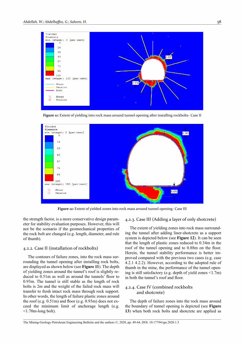
The extent of yield zones clearly occurs in the same locations around the tunnel as depicted below (see Fig-ure 10). It can be seen that the length of failure zones into the rock mass around the tunnel’s roof reaches up to 0.54m and about 1.13m in the tunnel’s floor. Also, yield zones occurred around the shoulders of the tunnel (e.g., bottom left and top right). According to the applied rule of thumb, the instability condition of the tunnel occurs if the length of yield zones exceeds 1.7m. Based on this analysis, the behaviour of the tunnel opening, either around the roof (e.g. yield length is 0.54m) or floor (e.g. yield length is 1.13m), is still satisfactory. Comparing yielding failure with the strength factor evaluation crite-rion (e.g. sec. 4.1.1), the analysis shows that the latter,
Figure 9: Strength factor contours after applying shotcrete and rockbolts- Case IV
Figure 10: Extent of yielding zones into the rock mass around the tunnel opening- case I
Abdellah, W.; Abdelhaffez, G.; Saleem, H. 58
The Mining-Geology-Petroleum Engineering Bulletin and the authors ©, 2020, pp. 49-64, DOI: 10.17794/rgn.2020.1.5
the strength factor, is a more conservative design param-eter for stability evaluation purposes. However, this will not be the scenario if the geomechanical properties of the rock bolt are changed (e.g. length, diameter, and rule of thumb).
4.2.2. Case II (installation of rockbolts)
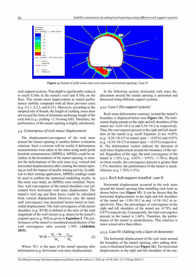
The contours of failure zones, into the rock mass sur-rounding the tunnel opening after installing rock bolts, are displayed as shown below (see Figure 11). The depth of yielding zones around the tunnel’s roof is slightly re-duced to 0.51m as well as around the tunnels’ floor to 0.93m. The tunnel is still stable as the length of rock bolts is 2m and the weight of the failed rock mass will transfer to fresh intact rock mass through rock support. In other words, the length of failure plastic zones around the roof (e.g. 0.51m) and floor (e.g. 0.93m) does not ex-ceed the minimum limit of anchorage length (e.g. <1.70m-long bolt).
4.2.3. Case III (Adding a layer of only shotcrete)
The extent of yielding zones into rock mass surround-ing the tunnel after adding liner-shotcrete as a support system is depicted below (see Figure 12). It can be seen that the length of plastic zones reduced to 0.34m in the roof of the tunnel opening and to 0.88m on the floor. Herein, the tunnel stability performance is better im-proved compared with the previous two cases (e.g. case 4.2.1 4.2.2). However, according to the adopted rule of thumb in the mine, the performance of the tunnel open-ing is still satisfactory (e.g. depth of yield zones <1.7m) in both the tunnel’s roof and floor.
4.2.4. Case IV (combined rockbolts and shotcrete)
The depth of failure zones into the rock mass around the boundary of tunnel opening is depicted (see Figure 13) when both rock bolts and shotcrete are applied as
Figure 11: Extent of yielding into rock mass around tunnel opening after installing rockbolts- Case II
Figure 12: Extent of yielded zones into rock mass around tunnel opening- Case III
59 Stability assessment of underground openings using different rock support systems
The Mining-Geology-Petroleum Engineering Bulletin and the authors ©, 2020, pp. 49-64, DOI: 10.17794/rgn.2020.1.5
rock support systems. That depth is significantly reduced to reach 0.24m in the tunnel’s roof and 0.78m on the floor. This means more improvement in tunnel perfor-mance stability compared with all three previous cases (e.g. 4.2.1, 4.2.2, and 4.23.). Moreover, according to the adopted rule of thumb, the length of yielding zones does not exceed the limit of minimum anchorage length of the rock bolt (e.g. yielding <1.7m-long left). Therefore, the performance of the tunnel opening is highly satisfactory.
4.3. Convergence of rock mass/ displacement
The displacement/convergence of the rock mass around the tunnel opening is another failure evaluation criterion. Such a criterion will be useful if deformation measurements were taken in the mine using multi-point borehole extensometers (MPBXs). MPBXs could be in-stalled, in the boundaries of the tunnel opening, to mon-itor the deformations of the rock mass (e.g. vertical and horizontal displacements) after creating the tunnel open-ing as well the impact of nearby mining activity. In addi-tion to their mining application, MPBXs readings could be used to confirm the numerical modelling results. In this mine case study, no MPBXs were installed. There-fore, wall convergence of the tunnel shoulders was cal-culated from horizontal rock mass displacement. The tunnel’s roof sag and floor heave could be calculated from vertical displacement. However, only the tunnel wall convergence was presented herein based on hori-zontal displacement. The wall convergence of the tunnel shoulders (e.g. WCR) is defined as the ratio of the total magnitude of the wall closure (e.g. Δmax) to the tunnel’s original span (e.g. W0) as given in Equation 2. The per-formance of the tunnel is considered unsatisfactory if the wall convergence ratio exceeds 1.50% (Abdellah, 2015).
(2)
Where: W1: is the span of the tunnel opening after deformation (e.g. horizontal rock mass displacement).
In the following section, horizontal rock mass dis-placement around the tunnel opening is presented and discussed using different support systems.
4.3.1. Case I (No support system)
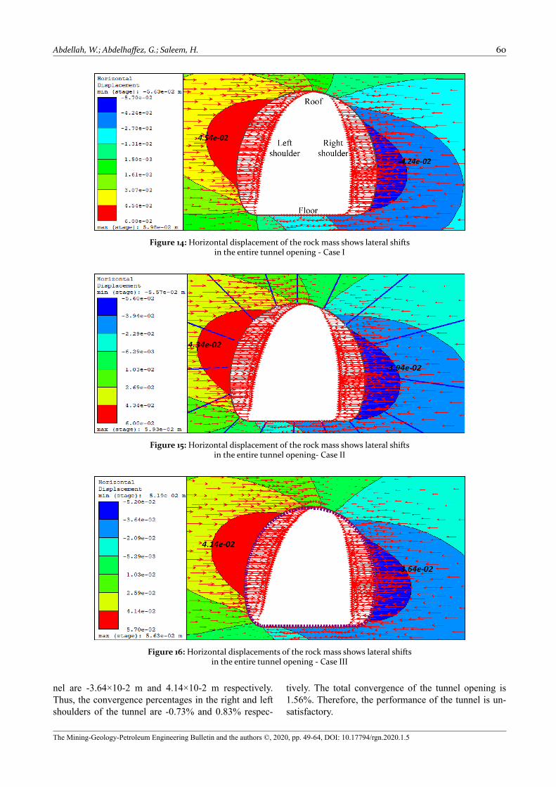
Rock mass deformation contours, around the tunnel’s boundary is displayed below (see Figure 14). The hori-zontal displacements at the right and left shoulders of the tunnel are -4.24×10⁻² m and 4.54×10⁻² m respectively. Thus, the convergence percent in the right and left shoul-ders of the tunnel (e.g. recall Equation 2) are -0.85% (e.g. -4.24×10⁻²/5 m tunnel span = -0.85%) and 0.91% (e.g. +4.54×10⁻²/5 m tunnel span = +0.91%) respective-ly. The deformation vectors indicate the direction of rock mass displacement around the boundary of the tun-nel. Regardless of the sign, the total convergence of the tunnel is 1.76% (e.g., 0.85% + 0.91% =1.76%). Based on these results, the convergence percent is greater than 1.5%; therefore, the performance of the tunnel is unsat-isfactory (e.g. 1.76%>1.5%).
4.3.2. Rock bolt support installed- case II
Horizontal displacement occurred in the rock mass around the tunnel opening after installing rock bolts as shown below (see Figure 15). It can be shown that the horizontal displacements in the right and left shoulders of the tunnel are -3.94×10⁻² m and +4.34×10⁻² m re-spectively. Thus, the percentages of convergence in the right and left shoulders of the tunnel are -0.79% and 0.87% respectively. Consequently, the total convergence percent in the tunnel is 1.66%. Therefore, the perfor-mance of the tunnel is unsatisfactory. This criterion is more conservative than others.
4.3.3. Case III (Adding only a layer of shotcrete)
The horizontal displacement of the rock mass around the boundary of the tunnel opening, after adding shot-crete is illustrated below (see Figure 16). The horizontal displacements in the right and left shoulders of the tun-
Figure 13: Extent of yield zones into rock mass around tunnel opening- Case IV
Abdellah, W.; Abdelhaffez, G.; Saleem, H. 60
The Mining-Geology-Petroleum Engineering Bulletin and the authors ©, 2020, pp. 49-64, DOI: 10.17794/rgn.2020.1.5
Figure 14: Horizontal displacement of the rock mass shows lateral shifts in the entire tunnel opening - Case I
Figure 15: Horizontal displacement of the rock mass shows lateral shifts in the entire tunnel opening- Case II
Figure 16: Horizontal displacements of the rock mass shows lateral shifts in the entire tunnel opening - Case III
nel are -3.64×10⁻² m and 4.14×10⁻² m respectively. Thus, the convergence percentages in the right and left shoulders of the tunnel are -0.73% and 0.83% respec-
tively. The total convergence of the tunnel opening is 1.56%. Therefore, the performance of the tunnel is un-satisfactory.
61 Stability assessment of underground openings using different rock support systems
The Mining-Geology-Petroleum Engineering Bulletin and the authors ©, 2020, pp. 49-64, DOI: 10.17794/rgn.2020.1.5
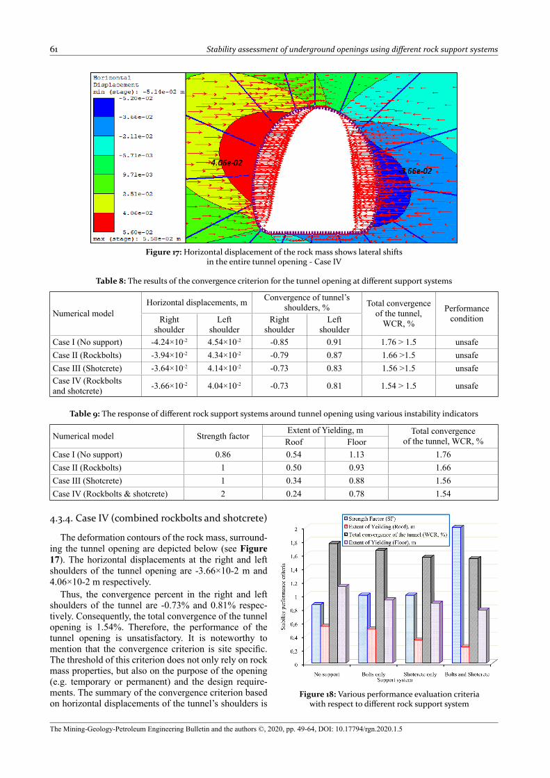
4.3.4. Case IV (combined rockbolts and shotcrete)
The deformation contours of the rock mass, surround-ing the tunnel opening are depicted below (see Figure 17). The horizontal displacements at the right and left shoulders of the tunnel opening are -3.66×10⁻² m and 4.06×10⁻² m respectively.
Thus, the convergence percent in the right and left shoulders of the tunnel are -0.73% and 0.81% respec-tively. Consequently, the total convergence of the tunnel opening is 1.54%. Therefore, the performance of the tunnel opening is unsatisfactory. It is noteworthy to mention that the convergence criterion is site specific. The threshold of this criterion does not only rely on rock mass properties, but also on the purpose of the opening (e.g. temporary or permanent) and the design require-ments. The summary of the convergence criterion based on horizontal displacements of the tunnel’s shoulders is
Figure 17: Horizontal displacement of the rock mass shows lateral shifts in the entire tunnel opening - Case IV
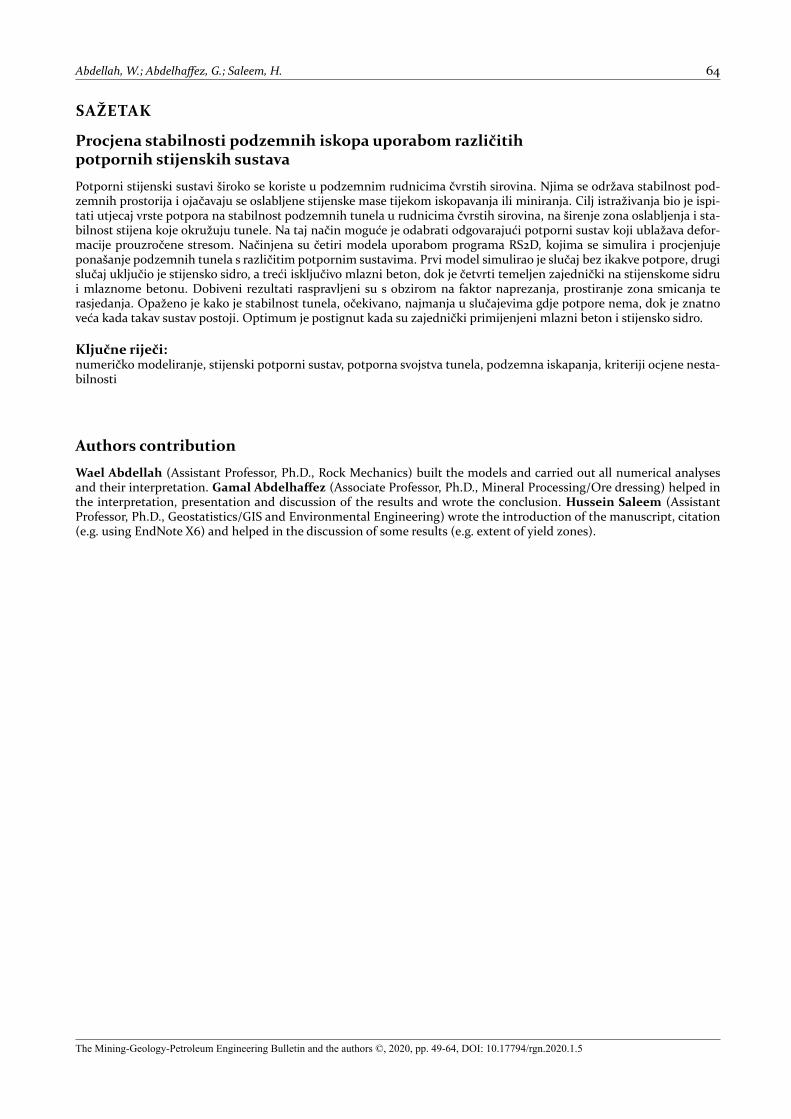
Figure 18: Various performance evaluation criteria with respect to different rock support system
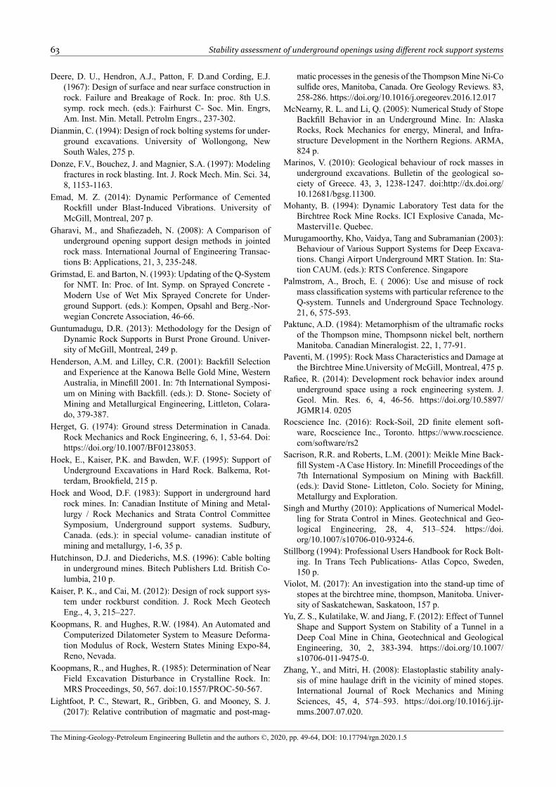
Table 9: The response of different rock support systems around tunnel opening using various instability indicators
Numerical model Strength factorExtent of Yielding, m Total convergence
of the tunnel, WCR, %Roof FloorCase I (No support) 0.86 0.54 1.13 1.76Case II (Rockbolts) 1 0.50 0.93 1.66Case III (Shotcrete) 1 0.34 0.88 1.56Case IV (Rockbolts & shotcrete) 2 0.24 0.78 1.54
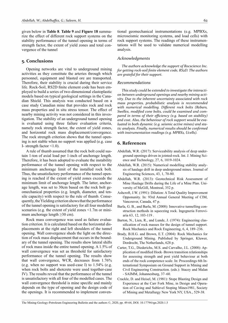
Table 8: The results of the convergence criterion for the tunnel opening at different support systems
Numerical modelHorizontal displacements, m Convergence of tunnel’s
shoulders, % Total convergence of the tunnel,
WCR, %
Performance conditionRight
shoulderLeft
shoulderRight
shoulderLeft
shoulderCase I (No support) -4.24×10⁻² 4.54×10⁻² -0.85 0.91 1.76 > 1.5 unsafeCase II (Rockbolts) -3.94×10⁻² 4.34×10⁻² -0.79 0.87 1.66 >1.5 unsafeCase III (Shotcrete) -3.64×10⁻² 4.14×10⁻² -0.73 0.83 1.56 >1.5 unsafeCase IV (Rockbolts and shotcrete) -3.66×10⁻² 4.04×10⁻² -0.73 0.81 1.54 > 1.5 unsafe
Abdellah, W.; Abdelhaffez, G.; Saleem, H. 62
The Mining-Geology-Petroleum Engineering Bulletin and the authors ©, 2020, pp. 49-64, DOI: 10.17794/rgn.2020.1.5
given below in Table 8. Table 9 and Figure 18 summa-rize the effect of different rock support systems on the stability performance of the tunnel opening in terms of strength factor, the extent of yield zones and total con-vergence of the tunnel
5. Conclusions
Opening networks are vital to underground mining activities as they constitute the arteries through which personnel, equipment and blasted ore are transported. Therefore, their stability is crucial during their service life. Rock-Soil, RS2D finite element code has been em-ployed to build a series of two-dimensional elastoplastic models based on typical geological settings in the Cana-dian Shield. This analysis was conducted based on a case study Canadian mine that provides rock and rock mass properties and in situ stress tensor. The effect of nearby mining activity was not considered in this inves-tigation. The stability of an underground tunnel opening is evaluated using three failure evaluation criteria, namely rock strength factor, the extent of yield zones, and horizontal rock mass displacement/convergence. The rock strength criterion shows that the tunnel open-ing is not stable when no support was applied (e.g. case I- strength factor <1.0).
A rule of thumb assumed that the rock bolt could sus-tain 1-ton of axial load per 1-inch of anchorage length. Therefore, it has been adopted to evaluate the instability performance of the tunnel opening with respect to the minimum anchorage limit of the installed rock bolt. Thus, the unsatisfactory performance of the tunnel open-ing is reached if the extent of yield zones exceeds the minimum limit of anchorage length. The latter, anchor-age length, was set to 30cm based on the rock bolt ge-omechanical properties (e.g. length, diameter, and ten-sile capacity) with respect to the rule of thumb. Conse-quently, the Yielding criterion shows that the performance of the tunnel opening is satisfactory for all four modelled scenarios (e.g. the extent of yield zones <1.7m or mini-mum anchorage length ≥30 cm).
Rock mass convergence was used as failure evalua-tion criterion. It is calculated based on the horizontal dis-placements at the right and left shoulders of the tunnel opening. Wall convergence sheds the light on the direc-tion of rock mass displacement that occurs in the bound-ary of the tunnel opening. The results show lateral shifts of rock mass inside the entire tunnel opening. A 1.5% of wall convergence was set as threshold for satisfactory performance of the tunnel opening. The results show that wall convergence, WCR, decreases from 1.76% (e.g. when no support was used-case I) to 1.54% (e.g. when rock bolts and shotcrete were used together-case IV). The results reveal that the performance of the tunnel is unsatisfactory with all four of the modelled cases. The wall convergence threshold is mine specific and mainly depends on the type of opening and the design code of the openings. It is recommended to implement conven-
tional geomechanical instrumentations (e.g. MPBXs, microseismic monitoring systems, and load cells) with rock support systems. The readings of these instrumen-tations will be used to validate numerical modelling analysis.
Acknowledgments
The authors acknowledge the support of Rocscience Inc. for getting rock-soil finite element code, RS2D. The authors are grateful for their support.
Recommendations
This study could be extended to investigate the interacti-on between underground openings and nearby mining acti-vity. Due to the inherent uncertainty associated with rock mass properties, probabilistic analysis is recommended with numerical modelling. Different rock bolts (Rebars, Swellex, modified cone bolts, could be examined and com-pared in terms of their efficiency (e.g. based on stability) and cost. Also, the behaviour of rock support would be eva-luated in both dynamic (e.g. seismic active mines) and sta-tic analysis. Finally, numerical results should be confirmed with instrumentation readings (e.g. MPBXs, Ucells).
6. References
Abdellah, W.R. (2017): Serviceability analysis of deep under-ground openings driven in jointed-rock. Int. J. Mining Sci-ence and Technology, 27, 6, 1019-1024.
Abdellah, W.R. (2015): Numerical modelling stability analy-sis of haulage drift in deep underground mines. Journal of Engineering Sciences, 43, 1, 70-80.
Abdellah, W.R. (2013): Geotechnical Risk Assessment of Mine Haulage Drifts during the Life of a Mine Plan. Uni-versity of McGill, Montreal, 352 p.
Ashcroft, J.W. (1991): Dilution: A Total Quality Improvement Opponunity. In: 93rd Annual General Meeting of CIM, Vancouver, Canada, 47 p.
Barla, G. B., and Barla, M. (2008): Innovative tunnelling con-struction methods in squeezing rock. Ingegneria Ferrovi-aria 63, 12, 103-119 .
Barton, N., Lien, R., and Lunde, J. (1974): Engineering clas-sification of rock masses for the design of tunnel support. Rock Mechanics and Rock Engineering, 6, 4, 189–236.
Brady, B.H.G. and Brown, E.T. (2004): Rock Mechanics for Underground Mining. Published by Springer, Kluwer, Dordrecht, The Netherlands, 628 p.
Carter, T.G., Diederichs, M.S. and Carvalho, J.L. (2008): Ap-plication of modified Hoek–Brown transition relationships for assessing strength and post yield behaviour at both ends of the rock competence scale. In: Proceedings 6th In-ternational Symposium on Ground Support in Mining and Civil Engineering Construction. (eds.): Stacey and Malan - SAIMM, Johannesburg, 37–60.
Crackle, D. and Heisel, M. (1981): Stope Blasting Design and Experience at the Carr Fork Mine, in Design and Opera-tion of Caving and Sublevel Stoping Mines1981, Society of Mining and Metallurgy New York NY, USA., 529-38.
63 Stability assessment of underground openings using different rock support systems
The Mining-Geology-Petroleum Engineering Bulletin and the authors ©, 2020, pp. 49-64, DOI: 10.17794/rgn.2020.1.5
Deere, D. U., Hendron, A.J., Patton, F. D.and Cording, E.J. (1967): Design of surface and near surface construction in rock. Failure and Breakage of Rock. In: proc. 8th U.S. symp. rock mech. (eds.): Fairhurst C- Soc. Min. Engrs, Am. Inst. Min. Metall. Petrolm Engrs., 237-302.
Dianmin, C. (1994): Design of rock bolting systems for under-ground excavations. University of Wollongong, New South Wales, 275 p.
Donze, F.V., Bouchez, J. and Magnier, S.A. (1997): Modeling fractures in rock blasting. Int. J. Rock Mech. Min. Sci. 34, 8, 1153-1163.
Emad, M. Z. (2014): Dynamic Performance of Cemented Rockfill under Blast-Induced Vibrations. University of McGill, Montreal, 207 p.
Gharavi, M., and Shafiezadeh, N. (2008): A Comparison of underground opening support design methods in jointed rock mass. International Journal of Engineering Transac-tions B: Applications, 21, 3, 235-248.
Grimstad, E. and Barton, N. (1993): Updating of the Q-System for NMT. In: Proc. of Int. Symp. on Sprayed Concrete - Modern Use of Wet Mix Sprayed Concrete for Under-ground Support. (eds.): Kompen, Opsahl and Berg.-Nor-wegian Concrete Association, 46-66.
Guntumadugu, D.R. (2013): Methodology for the Design of Dynamic Rock Supports in Burst Prone Ground. Univer-sity of McGill, Montreal, 249 p.
Henderson, A.M. and Lilley, C.R. (2001): Backfill Selection and Experience at the Kanowa Belle Gold Mine, Western Australia, in Minefill 2001. In: 7th International Symposi-um on Mining with Backfill. (eds.): D. Stone- Society of Mining and Metallurgical Engineering, Littleton, Colara-do, 379-387.
Herget, G. (1974): Ground stress Determination in Canada. Rock Mechanics and Rock Engineering, 6, 1, 53-64. Doi: https://doi.org/10.1007/BF01238053.
Hoek, E., Kaiser, P.K. and Bawden, W.F. (1995): Support of Underground Excavations in Hard Rock. Balkema, Rot-terdam, Brookfield, 215 p.
Hoek and Wood, D.F. (1983): Support in underground hard rock mines. In: Canadian Institute of Mining and Metal-lurgy / Rock Mechanics and Strata Control Committee Symposium, Underground support systems. Sudbury, Canada. (eds.): in special volume- canadian institute of mining and metallurgy, 1-6, 35 p.
Hutchinson, D.J. and Diederichs, M.S. (1996): Cable bolting in underground mines. Bitech Publishers Ltd. British Co-lumbia, 210 p.
Kaiser, P. K., and Cai, M. (2012): Design of rock support sys-tem under rockburst condition. J. Rock Mech Geotech Eng., 4, 3, 215–227.
Koopmans, R. and Hughes, R.W. (1984). An Automated and Computerized Dilatometer System to Measure Deforma-tion Modulus of Rock, Western States Mining Expo-84, Reno, Nevada.
Koopmans, R., and Hughes, R. (1985): Determination of Near Field Excavation Disturbance in Crystalline Rock. In: MRS Proceedings, 50, 567. doi:10.1557/PROC-50-567.
Lightfoot, P. C., Stewart, R., Gribben, G. and Mooney, S. J. (2017): Relative contribution of magmatic and post-mag-
matic processes in the genesis of the Thompson Mine Ni-Co sulfide ores, Manitoba, Canada. Ore Geology Reviews. 83, 258-286. https://doi.org/10.1016/j.oregeorev.2016.12.017
McNearny, R. L. and Li, Q. (2005): Numerical Study of Stope Backfill Behavior in an Underground Mine. In: Alaska Rocks, Rock Mechanics for energy, Mineral, and Infra-structure Development in the Northern Regions. ARMA, 824 p.
Marinos, V. (2010): Geological behaviour of rock masses in underground excavations. Bulletin of the geological so-ciety of Greece. 43, 3, 1238-1247. doi:http://dx.doi.org/ 10.12681/bgsg.11300.
Mohanty, B. (1994): Dynamic Laboratory Test data for the Birchtree Rock Mine Rocks. ICI Explosive Canada, Mc-Mastervil1e. Quebec.
Murugamoorthy, Kho, Vaidya, Tang and Subramanian (2003): Behaviour of Various Support Systems for Deep Excava-tions. Changi Airport Underground MRT Station. In: Sta-tion CAUM. (eds.): RTS Conference. Singapore
Palmstrom, A., Broch, E. ( 2006): Use and misuse of rock mass classification systems with particular reference to the Q-system. Tunnels and Underground Space Technology. 21, 6, 575-593.
Paktunc, A.D. (1984): Metamorphism of the ultramafic rocks of the Thompson mine, Thompsonn nickel belt, northern Manitoba. Canadian Mineralogist. 22, 1, 77-91.
Paventi, M. (1995): Rock Mass Characteristics and Damage at the Birchtree Mine.University of McGill, Montreal, 475 p.
Rafiee, R. (2014): Development rock behavior index around underground space using a rock engineering system. J. Geol. Min. Res. 6, 4, 46-56. https://doi.org/10.5897/JGMR14. 0205
Rocscience Inc. (2016): Rock-Soil, 2D finite element soft-ware, Rocscience Inc., Toronto. https://www.rocscience.com/software/rs2
Sacrison, R.R. and Roberts, L.M. (2001): Meikle Mine Back-fill System -A Case History. In: Minefill Proceedings of the 7th International Symposium on Mining with Backfill. (eds.): David Stone- Littleton, Colo. Society for Mining, Metallurgy and Exploration.
Singh and Murthy (2010): Applications of Numerical Model-ling for Strata Control in Mines. Geotechnical and Geo-logical Engineering, 28, 4, 513–524. https://doi.org/10.1007/s10706-010-9324-6.
Stillborg (1994): Professional Users Handbook for Rock Bolt-ing. In Trans Tech Publications- Atlas Copco, Sweden, 150 p.
Violot, M. (2017): An investigation into the stand-up time of stopes at the birchtree mine, thompson, Manitoba. Univer-sity of Saskatchewan, Saskatoon, 157 p.
Yu, Z. S., Kulatilake, W. and Jiang, F. (2012): Effect of Tunnel Shape and Support System on Stability of a Tunnel in a Deep Coal Mine in China, Geotechnical and Geological Engineering, 30, 2, 383-394. https://doi.org/10.1007/s10706-011-9475-0.
Zhang, Y., and Mitri, H. (2008): Elastoplastic stability analy- sis of mine haulage drift in the vicinity of mined stopes. International Journal of Rock Mechanics and Mining Sciences, 45, 4, 574–593. https://doi.org/10.1016/j.ijr-mms.2007.07.020.
Abdellah, W.; Abdelhaffez, G.; Saleem, H. 64
The Mining-Geology-Petroleum Engineering Bulletin and the authors ©, 2020, pp. 49-64, DOI: 10.17794/rgn.2020.1.5
SAŽETAK
Procjena stabilnosti podzemnih iskopa uporabom različitih potpornih stijenskih sustava
Potporni stijenski sustavi široko se koriste u podzemnim rudnicima čvrstih sirovina. Njima se održava stabilnost pod-zemnih prostorija i ojačavaju se oslabljene stijenske mase tijekom iskopavanja ili miniranja. Cilj istraživanja bio je ispi-tati utjecaj vrste potpora na stabilnost podzemnih tunela u rudnicima čvrstih sirovina, na širenje zona oslabljenja i sta-bilnost stijena koje okružuju tunele. Na taj način moguće je odabrati odgovarajući potporni sustav koji ublažava defor-macije prouzročene stresom. Načinjena su četiri modela uporabom programa RS2D, kojima se simulira i procjenjuje ponašanje podzemnih tunela s različitim potpornim sustavima. Prvi model simulirao je slučaj bez ikakve potpore, drugi slučaj uključio je stijensko sidro, a treći isključivo mlazni beton, dok je četvrti temeljen zajednički na stijenskome sidru i mlaznome betonu. Dobiveni rezultati raspravljeni su s obzirom na faktor naprezanja, prostiranje zona smicanja te rasjedanja. Opaženo je kako je stabilnost tunela, očekivano, najmanja u slučajevima gdje potpore nema, dok je znatno veća kada takav sustav postoji. Optimum je postignut kada su zajednički primijenjeni mlazni beton i stijensko sidro.
Ključne riječi: numeričko modeliranje, stijenski potporni sustav, potporna svojstva tunela, podzemna iskapanja, kriteriji ocjene nesta-bilnosti
Authors contribution
Wael Abdellah (Assistant Professor, Ph.D., Rock Mechanics) built the models and carried out all numerical analyses and their interpretation. Gamal Abdelhaffez (Associate Professor, Ph.D., Mineral Processing/Ore dressing) helped in the interpretation, presentation and discussion of the results and wrote the conclusion. Hussein Saleem (Assistant Professor, Ph.D., Geostatistics/GIS and Environmental Engineering) wrote the introduction of the manuscript, citation (e.g. using EndNote X6) and helped in the discussion of some results (e.g. extent of yield zones).