Embed Size (px)
Citation preview

Shyam Sundar Khadka et. al. / International Journal of New Technologies in Science and Engineering
Vol. 2, Issue. 2, 2015, ISSN 2349-0780
`
Available online @ www.ijntse.com 85
Stability Assessment of Hydropower Tunnel in
Lesser Himalayan Region of Nepal: Case
Study of Kulekhani-III Hydroelectric Project
Shyam Sundar Khadka, Nitesh Shrestha, Manab Rijal, Ayush Sharma Bhattarai, Ramesh Maskey
Department of Civil and Geomatics Engineering, Kathmandu University, Nepal
[email protected], [email protected]
Abstract: Due to weak rock mass quality and high overburden
most of hydropower tunnels have squeezing problems. The induced
stress level exceeds the strength of rock mass tunnel fails. Stress
plays a crucial role in developing brittle fractures, rock strength
reduction and rock mass instabilities The critical stress is an
indicator for the support design of tunnel. To quantify stress state
and deformation of circular tunnel, an empirical, semi emprical,
analytical and a two-dimensional boundary element numerical
investigation have been performed in this paper. Finite element
modeling results highlight that the shape and size of the tunnel,
existence geological structures and rock-mass parameters have
significant influence to the induced stress field and rock
deformation which directly controls the stability of the
underground excavation design.
Keywords: Tunnel, Support system, Convergence -Confinement
Method, Finite element modeling
I. INTRODUCTION
Nepal has the longest range of Himalaya extending 800 km from
west to east, occupies the center Himalaya range. Construction of
underground structures such as tunnels and shafts encounter various
risk and uncertainties in this region. The major stability problems
during tunneling in Lesser Himalayan region of Nepal are: weak
rock mass quality, high degree of weathering and fracturing, rock
stress and Ground Water Effect. In Himalayas of Nepal, tunnel
squeezing is a common phenomenon (Panthi, 2006) as the fault
zone weak rocks (eg: mudstone, slate, phyllite, and schist highly
schistose gneiss) that compose the mountains are not capable of
withstanding high stress. In general, Tunneling through such weak
rock mass may cause severe squeezing problems and is one of the
major areas of concern regarding stability. Many hydropower
tunnels like Kaligandaki A, Middle Marsyangdi, Modi and Khimti
respectively have considerable amount of squeezing occurred while
tunneling. These all tunnels lies in Lesser Himalaya and have high
overburden pressure with weak geology. The study of stability of
tunnel needs a special attention in a mountainous country, because
of the diverse geology and difficult terrain of the country. The
mountainous topography causes high overburden pressure in the
underground structure causing squeezing and other stability
problems. However, due to few detail studies on ever changing
Himalayan region and geological condition in Nepal, it has been
difficult to predict the effect of geology in underground structure.
Nepal Himalaya can be divided into 4 major tectonic thrust faults:
Main Frontal Thrust (MFT), Main Central Thrust (MCT), Main
Boundary Thrust (MBT) and South Tibetan Detachment Thrust
(STDS).Predicting rock mass quality and analyzing stress induced
problems has been challenging task in these regions. Thus extensive
researches are to be carried out to incorporate necessary measures to
rectify all geological problems.
II. KULEKHANI-III HYDROELECTRIC PROJECT
Fig. 1 Penstock tunnel at KL-III HPP

Shyam Sundar Khadka et. al. / International Journal of New Technologies in Science and Engineering
Vol. 2, Issue. 2, 2015, ISSN 2349-0780
`
Available online @ www.ijntse.com 86
Kulekhani Hydropower is the only storage project of Nepal.
Kulekhani-III (KL-III) hydroelectric project is the cascade scheme
of Kulekhani storage project with an installed capacity of 14 MW.
KL-III power station is the scheme to utilize the regulated flow of
Kulekhani reservoir via tailrace of KL-II along with water from
Khani Khola. The location of this project is Makawanpur district,
Narayani Zone of Central development region in Rapti river basin.
This project is located at lesser Himalaya of Nepal in between Main
boundary Thrust (MBT) and Main Frontal Thrust (MFT).
Fig. 2 Rock Mass along Inclined Tunnel Alignment
The project area lies in the southernmost part of Kathmandu
Synclinorium characterized by meta-sedimentary rocks of Nuwakot
complex and crystalline rock of Kathmandu complex. The penstock
region is hosted by poor quality, Slaty phyllite characterized by
black carbonaceous slate and dark grey slates and phyllite. The
general trend of foliation is almost east to west and dips moderately
towards north. Terrace deposits are present at the top of penstock
alignment. During excavation, rock support measures have been
applied along the length of tunnel.
Fig. 3 Support system (R4) for inclined penstock as KL-III HPP
Regarding rock mass parameters, no tests were performed during
the study period. Values have been estimated during face mapping,
and rock types and support types were classified. Other parameters,
such as unconfined compressive strength of the intact rock, Young’s
modulus of the intact rock, density of the rock, and Poisson’s ratio
were estimated by using RocLab software.
III. ROCK MASS CLASSIFICATION
Rock condition of KL-III has been classified into four classes,
viz., Q1, Q2, Q3 and Q4 with corresponding rock support rock
supports R1, R2, R3 and R4. Rock mass at penstock portion has
been considered as Q4 and rock support R4 has been applied here as
shown in Fig2.Slaty phyllite along inclined tunnel has Q value
ranging from 0.17 to 0.44, suggesting the rock class to be of very
poor type. These rocks are highly foliated, moderately weathered
with the uniaxial strength reduction up to 60 %.
Table 1: Rock Mass Classification for Rock along Inclined
Penstock
IV.ELASTIC STRESS DISTRIBUTION AROUND
PENSTOCK TUNNEL
Rock Mass
Quality
Rock
Class
Rock Support
Class
Q value
Very poor Q4 R4 0.1<Q<1
Poor Q3 R3 1<Q<4
Fair Q2 R2 4<Q<10
Good Q1 R1 10<Q<40

Shyam Sundar Khadka et. al. / International Journal of New Technologies in Science and Engineering
Vol. 2, Issue. 2, 2015, ISSN 2349-0780
`
Available online @ www.ijntse.com 87
When an underground opening is excavated, the insitu stress is
redistributed in the surrounding rock. The rock mass is
homogeneous, hydrostatic stress condition, isotropic, linearly elastic
and infinite medium. The stress around the opening with radius ri,
depends on the radius r from the circle center. The radial and
tangential stress Ϭr and ϬƟ respectively are given by:
Ϭr=Ϭ (1- 𝑟𝑖2
𝑟2) (1)
ϬƟ= Ϭ (1+𝑟𝑖2
𝑟2) (2)
The stress distribution is such that the tangential stress is twice
the magnitude of the iso-static stress, gets induced around
periphery of the excavation. For the weak rocks they undergo
plastic deformation. Once support is installed to the opening,
stress redistribution takes place
Table 2: Data used for plotting stress distribution in rock zone at
inclined tunnel
Parameters Value
Radius of tunnel
Insitu Stress(Ϭo)
1.75 m
2.17 MPa
Specific Weight of Rock 27.8 kN/m3
Uniaxial Compressive Strength (Ϭci)
Support Pressure provided
10.34 MPa
0.90 MPa
Poisson Ratio 0.25
Fig.4 shows stress distribution around elastic rock mass in
circular tunnel at chain age 4+451 m. The tangential stress decreases
with increase in distance from center of circle from 2*Ϭo= 4.34 MPa
to Ϭo=2.17 MPa exponentially. At the same time, radial stress
increases from 0 to Ϭo=2.17 MPa and Fig.5 shows stress distribution
at elasto plastic rock zone w/o support condition. Value of ϬƟ rises
up to 2.5 MPa at elastic zone and decreases to Ϭo=2.17 MPa
subsequently. Similarly, value of Ϭr increases to Ϭo =2.17
asymptotically.
Fig. 4 Radial and tangential stress distribution around Elastic Rock
Mass in at inclined tunnel KL-III
Fig. 5 Stress distribution at elasto plastic rock zone at inclined
tunnel KL-III
Fig. 5 suggests that the support affects the stress condition .The
stress level at opening contour increases and the stress peak level
decreases(Goodman,1989).Support provides the confining
pressure(support pressure) and helps rock mass to take more
stress(Mohr Coulomb).Value of ϬƟ is reduced to 2.3 MPa at peak
region.
V. STABILITY ASSESSMENT
Squeezing of rock is the time dependent large deformation, which
occurs around the tunnel, and is essentially associated with creep
caused by exceeding a limiting shear stress(International Society for
Rock Mechanics,1995).Deformation and insitu pressure are
interdependent. Confinement Convergence Method (Carranza-
Torres and Fair Hurst 2000) with the Hoek and Brown failure
criteria (Hoek et al 2002) and 2D finite element numerical analysis
using roc science.V.9.0 were used to analyze squeezing phenomena.
A. Singh et al (1992) approach The empirical approach based on the rock mass classification
scheme is used to assess squeezing of rock. Singh et al (1992) is
based on 39 case histories with data on rock mass quality index Q
(Barton et al 1974) and overburden depth H. This approach gives a
clear demarcation line differentiating squeezing cases from non-
squeezing cases. Fig. 6 below indicates that the tunnel has no
squeezing problem along its alignment.
0
0.5
1
1.5
2
2.5
3
3.5
4
4.5
5
1 2 3 4 5 6 7 8 9 10
бθ
an
d б
r (M
pa)
r/ri
бθ curve
бr curve
0.0
0.5
1.0
1.5
2.0
2.5
3.0
0.0 5.0 10.0 15.0 20.0 25.0
бθ
an
d б
r (M
pa)
r/ri
бr w/o support
бθ w/o support
бr with support
бθ with support
Shyam Sundar Khadka et. al. / International Journal of New Technologies in Science and Engineering
Vol. 2, Issue. 2, 2015, ISSN 2349-0780
`
Available online @ www.ijntse.com 88
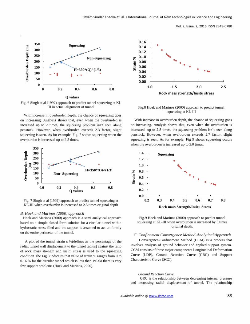
Fig. 6 Singh et al (1992) approach to predict tunnel squeezing at Kl-
III in actual alignment of tunnel
With increase in overburden depth, the chance of squeezing goes
on increasing. Analysis shows that, even when the overburden is
increased up to 2 times, the squeezing problem isn’t seen along
penstock. However, when overburden exceeds 2.3 factor, slight
squeezing is seen. As for example, Fig. 7 shows squeezing when the
overburden is increased up to 2.5 times.
Fig. 7 Singh et al (1992) approach to predict tunnel squeezing at
KL-III when overburden is increased to 2.5 times original depth
B. Hoek and Marinos (2000) approach Hoek and Marinos (2000) approach is a semi analytical approach
based on a simple closed form solution for a circular tunnel with a
hydrostatic stress filed and the support is assumed to act uniformly
on the entire perimeter of the tunnel.
A plot of the tunnel strain ἐ %(defines as the percentage of the
radial tunnel wall displacement to the tunnel radius) against the ratio
of rock mass strength and insitu stress is used to the squeezing
condition The Fig.8 indicates that value of strain % ranges from 0 to
0.16 % for the circular tunnel which is less than 1%.So there is very
few support problems (Hoek and Marinos, 2000).
Fig.8 Hoek and Marinos (2000) approach to predict tunnel
squeezing at KL-III
With increase in overburden depth, the chance of squeezing goes
on increasing. Analysis shows that, even when the overburden is
increased up to 2.5 times, the squeezing problem isn’t seen along
penstock. However, when overburden exceeds 2.7 factor, slight
squeezing is seen. As for example, Fig 9 shows squeezing occurs
when the overburden is increased up to 3.0 times.
Fig.9 Hoek and Marinos (2000) approach to predict tunnel
squeezing at KL-III when overburden is increased by 3 times
original depth.
C. Confinement Convergence Method-Analytical Approach
Convergence-Confinement Method (CCM) is a process that
involves analysis of ground behavior and applied support system.
CCM consists of three major components Longitudinal Deformation
Curve (LDP), Ground Reaction Curve (GRC) and Support
Characteristic Curve (SCC).
Ground Reaction Curve
GRC is the relationship between decreasing internal pressure
and increasing radial displacement of tunnel. The relationship
0
50
100
150
200
250
300
350
0 0.2 0.4 0.6 0.8
Over
bu
rden
Dep
th (
m)
Q values
H=350*(Q)^(1/3)
0
50
100
150
200
250
300
350
0.0 0.2 0.4 0.6 0.8
Over
bu
rden
Dep
th
(m)
Q values
H=350*(Q)^(1/3)
0.000.020.040.060.080.100.120.140.16
1.0 1.5 2.0 2.5
Stra
in%
Rock mass strength/Insitu stress
0.0
0.2
0.4
0.6
0.8
1.0
1.2
1.4
0.2 0.3 0.4 0.5 0.6 0.7 0.8
Str
ain
%
Rock mass Strength/Insitu Stress
Squeezing
Non-Squeezing
Squeezing
Non- Squeezing
Shyam Sundar Khadka et. al. / International Journal of New Technologies in Science and Engineering
Vol. 2, Issue. 2, 2015, ISSN 2349-0780
`
Available online @ www.ijntse.com 89
depends upon mechanical properties of rock mass and can be
obtained from elasto-plastic solution of rock deformation around an
excavation (Carranza-Torres and Fair Hurst 2000). GRC for slaty
phyllite has been constructed using the elasto-plastic solution or
circular opening subject to uniform far-field stresses and uniform
internal pressure.
The GRC has been constructed, considering the section 4+451 m
with the overburden height at penstock portion is equal to 77.93 m, the
maximum overburden pressure is 2.170 MPa calculated as the product
of unit weight γ and depth h. The GRC shown in Fig 11 illustrates the
critical pressure value (Pi cr) is 0.6 MPa, which marks the transition
from elastic to plastic behavior of the rock-mass. The maximum radial
displacement (urmax) is 13 mm at zero internal pressure (i.e., the tunnel
is unsupported).
Longitudinal Deformation Profile
LDP is the graphical representation of the radial displacement
that occurs along the axis of unsupported cylindrical excavation i.e.
for the sections located ahead of and behind tunnel face. It indicates
that at some distance behind tunnel face effect of face is negligibly
small so that beyond this distance tunnel has converged by final
value urmax.
The LDP curve has been constructed considering a face length of
1m. Radial displacement on unsupported wall goes on increasing
behind tunnel face and becomes maximum of 13 mm at 24 m behind
face. Similarly, the value decreases at head of face to zero at 15 m
head of face.
Support characteristic Curve
SCC is defined as the relationship between increasing pressure
on the support. It can be constructed from elastic relationship
between applied pressure Ps and resulting displacement ur for the
section of support of unit length in the direction of tunnel. If the
elastic stiffness of the support is Ks then,
Ps=Ks*u (3)
Support characteristic curve using bolt, Shotcrete, Blocked steel,
blocked steel+bolt and blocked steel+shotcrete are constructed.
Table 3 Data used for plotting CCM
Parameters Value
Radius of tunnel 1.75 m
Specific Weight of Rock 24.0 kN/m3
Face length
Insitu Stress (Ϭo)
1 m
2.170 MPa
Uniaxial Compressive Strength 10.34 MPa
Poisson Ratio 0.25
Geological Strength Index(GSI) 40
mi(dimensionless parameter) 12
s (dimensionless parameter) 0.00127
Shear Modulus 0.86 GPa
Coefficient of Lateral Pressure(k0) 2.46
Support Characteristic Curve for bolt
The maximum pressure provided by the support system
assuming that the bolts are equally spaced in the circumferential
direction is given as Carranza-Torres and Fair Hurst (2000)
𝑝𝑠𝑚𝑎𝑥 =𝑇𝑏𝑓
𝑆𝑐∗𝑆𝑙 (4)
1
𝐾𝑠= 𝑆𝑐 ∗ 𝑆𝑙(
4𝑙
𝛱∗𝑑2∗𝐸𝑠)+Q (5)
Where,
Psmax= maximum pressure provided by support system
Tbf= ultimate load obtained from pull out test
Sc=circumferential bolt spacing
SL=longitudinal bolt spacing
Ks=elastic stiffness constant
Q= deformation load constant
Es= Young’s modulus of bolt
Table 4 Data used for plotting SCC with bolts.
Parameters Value
Bolt diameter 25 mm
Ultimate load 0.1 MN
Deformation load constant 0.03 m/MN
Young Modulus 210 GPa
Longitudinal bolt spacing 1.5 m
Support Characteristic Curve for Shotcrete
The maximum pressure provided by the Shotcrete lining is
given as (Carranza-Torres and Fair Hurst 2000)
𝑝𝑠𝑚𝑎𝑥 =𝜎𝑐𝑐
2(1 − (1 −
𝑡𝑐
𝑟𝑅)2) (6)
Table 5 Data used for plotting SCC with concrete linings:
Parameters Value
Unconfined Compressive strength of
concrete
Young Modulus of Concrete
30 MPa
30 GPa
Poison ratio of Concrete 0.15
SFRS
Thickness of concrete fill
10 cm
60 cm
Wall displacement at face is less than 5 mm. At the face length,
which has been taken as 1 m the displacement is found to be about 8
mm. A minimum support pressure of approximately 0.02 MPa has
been provided by the bolts as shown in Fig 10.
KL-III HPP uses a support consisting of Concrete lining and
Bolt. The Fig.11 indicates that for a 3.5 m radius tunnel, the use of
shotcrete with lining and bolt provides the maximum support
pressure of about 0.90 MPa. A Steel Fiber Reinforced Shotcrete
(SFRS) 10 cm thick reinforced lining has been provided with 2.5 m
long bolt in KL-III. Fig 11 summarizes the CCM along with support
condition that has been applied at inclined tunnel at KL-III
Hydroelectric project.

Shyam Sundar Khadka et. al. / International Journal of New Technologies in Science and Engineering
Vol. 2, Issue. 2, 2015, ISSN 2349-0780
`
Available online @ www.ijntse.com 90
Fig. 10 SCC for circular tunnel at KL-III with various options
Fig. 11 CCM for circular tunnel at KL-III HPP with support
(Shotcrete +Bolt)
VI. RESULT OF FINITE ELEMENT ANALYSIS
2D finite element method with RocScience.V.9.0 was applied to
simulate the circular underground opening of KL-III HPP tunnel to
predict induced stress, state and deformations of the surrounding
rock masses during the excavation phase of circular tunnel.
A. Model geometry and mechanical parameters
All models were constructed on the basis of plane strain
condition.
Table 6 Mechanical properties of rock mass
Parameters Value
Specific Weight of slaty phyllite
Young Modulus (E)
0.0278 MN/m3
8000 MPa
Poison ratio 0.22
tensile strength
cohesion (c)
Angle of internal friction
3.5 MPa
0.01 MPa
25 degree
B. Distribution of maximum and minimum principal stress (σ1
and σ3)
Stresses were analyzed on the tunnel section 4+451.000 m of
KL-III project. Fig 14 and 15 show the magnitude and distribution
of the major principal stress trajectories along the tunnel section
without and with supports.σ1 stress is concentrated around the
tunnel face with a maximum value of 3.40 MPa at crown of
unsupported tunnel (Fig 12).This value decreases to 2.90 MPa when
support is installed (Fig 13).No shear and tension failure was
noticed when support system was installed in inclined tunnel. The
numerical simulation suggested that the value of σ3 ranged from
0.15MPa to 1.85 MPa. In the unsupported section the tunnel
boundary had maximum stress on tunnel crown. Side walls has
stress of 0.23 MPa. When the support were installed in the tunnel
the value of σ3 reduced to 1.80 MPa as shown in the Fig.15.
Fig. 12 Distribution of major principal stress (w/o support)
Fig.13 Distribution of major principal stress (with support)
0.0
0.2
0.4
0.6
0.8
1.0
0.0 5.0 10.0 15.0 20.0 25.0 30.0
Inte
rn
al
Pre
ssu
re P
i (M
Pa
)
Radial displacement (mm)
Bolts
Shotcrete or concrete
0 5 10 15
-20
-15
-10
-5
0
5
10
15
20
25
30
35
0
0.5
1
1.5
2
2.5
0 5 10 15
Radial displacement (mm)
Dis
tam
ce
alo
ng
ax
is o
f u
nsu
pp
ort
ed t
un
nel
exca
vati
on
Inte
rnal
pre
ssu
re (
MP
a)
Shotcrete or concrete+Bolt
Ground Reaction Curve
Shyam Sundar Khadka et. al. / International Journal of New Technologies in Science and Engineering
Vol. 2, Issue. 2, 2015, ISSN 2349-0780
`
Available online @ www.ijntse.com 91
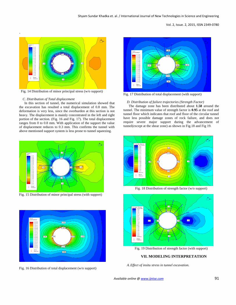
Fig. 14 Distribution of minor principal stress (w/o support)
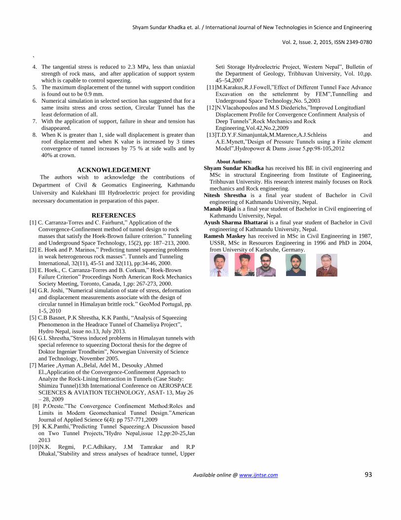
C. Distribution of Total displacement
In this section of tunnel, the numerical simulation showed that
the excavation has resulted a total displacement of 0.8 mm. The
deformation is very less, since the overburden at this section is not
heavy. The displacement is mainly concentrated in the left and right
portion of the section. (Fig. 16 and Fig. 17). The total displacement
ranges from 0 to 0.8 mm. With application of the support the value
of displacement reduces to 0.3 mm. This confirms the tunnel with
above mentioned support system is less prone to tunnel squeezing.
Fig. 15 Distribution of minor principal stress (with support)
Fig. 16 Distribution of total displacement (w/o support)
Fig. 17 Distribution of total displacement (with support)
D. Distribution of failure trajectories (Strength Factor)
The damage zone has been distributed about 1.58 around the
tunnel. The minimum value of strength factor is 0.95 at the roof and
tunnel floor which indicates that roof and floor of the circular tunnel
have less possible damage zones of rock failure, and does not
require severe major support during the advancement of
tunnel(except at the shear zone) as shown in Fig.18 and Fig 19.
Fig. 18 Distribution of strength factor (w/o support)
Fig. 19 Distribution of strength factor (with support)
VII. MODELING INTERPRETATION
A. Effect of insitu stress in tunnel excavation.

Shyam Sundar Khadka et. al. / International Journal of New Technologies in Science and Engineering
Vol. 2, Issue. 2, 2015, ISSN 2349-0780
`
Available online @ www.ijntse.com 92
The insitu stress at the location of an underground excavation
has the greatest impact on the stability. Both high stresses and low
stresses may reduce the stability of rock masses, particularly weak
and fragile rock masses. The excavation of tunnel disturbs the initial
stress condition as shown in Table 7.
Table 7: Variation of principal stresses and displacement with
increase in field stress.
Stress factor σ1(MPa) σ3(MPa) Displacement(mm)
1X 4.60 1.48
2X 7.00 5.15
3X 9.10 5.25
5X 13.20 8.40
10X 22.00 16.00
0.70 mm
1.85 mm
3.72 mm
10.18 mm
40.56 mm
B. Effect of size of excavation
The diameter of the tunnel at section 4+451 m was increased
and was modelled in roc science V.9.0 software. The increasing size
of tunnel has effectively influenced the stability of tunnel. All
parameters such as Ϭ1, Ϭ3 and deformation of tunnel has precisely
increased with increase in tunnel opening. Table 8 summarizes
result of 2D analysis on increasing tunnel diameter.
Table 8: Variation of principal stresses and displacement with
increase in tunnel size.
Size (Dia.) σ1(MPa) σ3(MPa) Displacement(mm)
3.5 m 4.6 1.48 0.70
7.0 m 3.4 1.85
9.0 m 3.34 1.85
1.50
1.90
12.0 m 3.34 1.85 3.00
Fig. 20 Influence of size on deformation in underground excavation
(Circular) at Kl-III
C. Effect of geometry of excavation
Table 9: Variation of principal stresses and displacement with
change in Tunnel geometry.
Shape σ1(MPa) σ3(MPa) Displacement(mm)
Circle 4.60 1.48
(3.5 m Ǿ)
0.71 mm
Square 4.20 1.60
(3.10 m)
Rectangle 4.20 1.60
(4*2.5 m)
0.95 mm
0.91 mm
D shaped 4.40 1.60
(D=3.28 m)
0.87 mm
For the same cross sectional area of the tunnel, numerical simulation
was done with various tunnel geometry. Table 9 suggests that
circular section has the least total displacement (0.70 mm) but is
acted upon by the maximum major principal stress (σ1=4.60 MPa)
of all. Similarly, square tunnel gave maximum value of
displacement (0.95 mm) thereby indicating higher possibility of
tunnel squeezing and extreme support systems.
D. Effect of K value
K value is defined as the ratio of the horizontal stress to vertical
stress. K value plays important role in influencing tunnel stability
parameters.
Table 10: Variation of displacement with change in value of k for a
tunnel of 3.5 m diameter.
K-value Deformation(Roof) Deformation (Side wall)
0.739 0.6 mm 0.4 mm
1.00 0.5 mm 0.6 mm
1.50 0.7 mm 1.0 mm
2.00 0.8 mm 1.4 mm
2.50 1.2 mm 1.9 mm
3.00 1.7 mm 2.4 mm
VII. CONCLUSION The fragile and tectonically active Himalayan region of Nepal
has various stability problem such as squeezing, ground water
problem, in-situ stresses, and roof collapse. Lack of proper Geo-
technical data and instrumentation brings challenges to predict such
problems and estimate required support pressure and tunnel closure.
The Inclined tunnel of KL-III does not have severe squeezing
problem. Empirical, semi-empirical, analytical and Numerical
investigation is applied to assess tunnel stability.
Following are the major conclusion drawn from this paper:
1. The existing empirical and semi empirical methods such as
Singh et al. (1992) and Hoek and Marinos (2000) are suitable for
stability analysis of underground structure in weak geology of
Himalaya of Nepal.
2. The existing inclined pressure tunnel has not suffered from the
squeezing problem. But, when the overburden depth of existing
tunnel is increased by 2 times, squeezing problem starts getting
noticeable as per empirical approach.
3. The analytical method is useful to calculate the support pressure
of inclined pressure tunnel. Support Pressure provided by the
combination of SFRS, Concrete lining and bolt in this tunnel is
about 0.90 MPa as per CCM analysis.
y = 0.162x1.1508
R² = 0.99
0
1
2
3
4
5
0 5 10 15 20
Def
orm
ati
on
(m
m)
Tunnel Diameter(m)
Shyam Sundar Khadka et. al. / International Journal of New Technologies in Science and Engineering
Vol. 2, Issue. 2, 2015, ISSN 2349-0780
`
Available online @ www.ijntse.com 93
4. The tangential stress is reduced to 2.3 MPa, less than uniaxial
strength of rock mass, and after application of support system
which is capable to control squeezing.
5. The maximum displacement of the tunnel with support condition
is found out to be 0.9 mm.
6. Numerical simulation in selected section has suggested that for a
same insitu stress and cross section, Circular Tunnel has the
least deformation of all.
7. With the application of support, failure in shear and tension has
disappeared.
8. When K is greater than 1, side wall displacement is greater than
roof displacement and when K value is increased by 3 times
convergence of tunnel increases by 75 % at side walls and by
40% at crown.
ACKNOWLEDGEMENT The authors wish to acknowledge the contributions of
Department of Civil & Geomatics Engineering, Kathmandu
University and Kulekhani III Hydroelectric project for providing
necessary documentation in preparation of this paper.
REFERENCES [1] C. Carranza-Torres and C. Fairhurst,” Application of the
Convergence-Confinement method of tunnel design to rock
masses that satisfy the Hoek-Brown failure criterion.” Tunneling
and Underground Space Technology, 15(2), pp: 187–213, 2000.
[2] E. Hoek and P. Marinos,” Predicting tunnel squeezing problems
in weak heterogeneous rock masses”. Tunnels and Tunneling
International, 32(11), 45-51 and 32(11), pp:34-46, 2000.
[3] E. Hoek., C. Carranza-Torres and B. Corkum,” Hoek-Brown
Failure Criterion” Proceedings North American Rock Mechanics
Society Meeting, Toronto, Canada, 1,pp: 267-273, 2000.
[4] G.R. Joshi, ”Numerical simulation of state of stress, deformation
and displacement measurements associate with the design of
circular tunnel in Himalayan brittle rock.” GeoMod Portugal, pp.
1-5, 2010
[5] C.B Basnet, P.K Shrestha, K.K Panthi, “Analysis of Squeezing
Phenomenon in the Headrace Tunnel of Chameliya Project”,
Hydro Nepal, issue no.13, July 2013.
[6] G.L Shrestha,”Stress induced problems in Himalayan tunnels with
special reference to squeezing Doctoral thesis for the degree of
Doktor Ingeniør Trondheim”, Norwegian University of Science
and Technology, November 2005.
[7] Mariee ,Ayman A.,Belal, Adel M., Desouky ,Ahmed
El.,Application of the Convergence-Confinement Approach to
Analyze the Rock-Lining Interaction in Tunnels (Case Study:
Shimizu Tunnel)13th International Conference on AEROSPACE
SCIENCES & AVIATION TECHNOLOGY, ASAT- 13, May 26
– 28, 2009
[8] P.Oreste.”The Convergence Confinement Method:Roles and
Limits in Modern Geomechanical Tunnel Design.”American
Journal of Applied Science 6(4): pp 757-771,2009
[9] K.K.Panthi,”Predicting Tunnel Squeezing:A Discussion based
on Two Tunnel Projects,”Hydro Nepal,issue 12,pp:20-25,Jan
2013
[10]N.K. Regmi, P.C.Adhikary, J.M Tamrakar and R.P
Dhakal,”Stability and stress analyses of headrace tunnel, Upper
Seti Storage Hydroelectric Project, Western Nepal”, Bulletin of
the Department of Geology, Tribhuvan University, Vol. 10,pp.
45–54,2007
[11]M.Karakus,R.J.Fowell,”Effect of Different Tunnel Face Advance
Excavation on the settelemrnt by FEM”,Tunnelling and
Underground Space Technology,No. 5,2003
[12]N.Vlacahopoulos and M.S Diederichs,”Improved Longitudianl
Displacement Profile for Convergence Confinment Analysis of
Deep Tunnels”,Rock Mechanics and Rock
Engineering,Vol.42,No.2,2009
[13]T.D.Y.F.Simanjuntak,M.Marence,A.J.Schleiss and
A.E.Mynett,”Design of Pressure Tunnels using a Finite element
Model”,Hydropower & Dams ,issue 5,pp:98-105,2012
About Authors:
Shyam Sundar Khadka has received his BE in civil engineering and
MSc in structural Engineering from Institute of Engineering,
Tribhuvan University. His research interest mainly focuses on Rock
mechanics and Rock engineering.
Nitesh Shrestha is a final year student of Bachelor in Civil
engineering of Kathmandu University, Nepal.
Manab Rijal is a final year student of Bachelor in Civil engineering of
Kathmandu University, Nepal.
Ayush Sharma Bhattarai is a final year student of Bachelor in Civil
engineering of Kathmandu University, Nepal.
Ramesh Maskey has received in MSc in Civil Engineering in 1987,
USSR, MSc in Resources Engineering in 1996 and PhD in 2004,
from University of Karlsruhe, Germany.


![Teaching Structural Geology, Geophysics, and Tectonics in ...serc.carleton.edu/files/NAGTWorkshops/structure/SGT2012/field_guide.pdfPigeon Siltstone / Metcalf Phyllite Yb *T]M :QLOM](https://img.pdfslide.us/doc/110x75/5f54a5d869af3a28d9699a2f/teaching-structural-geology-geophysics-and-tectonics-in-serc-pigeon-siltstone.jpg)