Embed Size (px)
Citation preview

NREL/CP-440-21679 • UC Category: 1211 • DE97000075
Stability Analysis of a Variable-Speed Wind Turbine
Gunjit S. Bir Alan D. Wright C.P. (Sandy) Butterfield
Prepared for 1997 ASME Wind Energy Symposium Reno, Nevada January 6-9, 1997
National Renewable Energy Laboratory 1617 Cole Boulevard Golden, Colorado 80401-3393 A national laboratory ofthe U.S. Department ofEnergy Managed by Midwest Research Institute for the U.S. Department ofEnergy under contract No. DE-AC36-83CH1 0093
Prepared under Task No. WE711210
October 1996
NOTICE
This report was prepared as an account of work sponsored by an agency of the United States government. Neither the United States government nor any agency thereof, nor any of their employees, makes any warranty, express or implied, or assumes any legal liability or responsibility for the accuracy, completeness, or usefulness of any information, apparatus, product, or process disclosed, or represents that its use would not infringe privately owned rights. Reference herein to any specific commercial product, process, or service by trade name, trademark, manufacturer, or otherwise does not necessarily constitute or imply its endorsement, recommendation, or favoring by the United States government or any agency thereof. The views and opinions of authors expressed herein do not necessarily state or reflect those of the United States government or any agency thereof.
Available to DOE and DOE contractors from: Office of Scientific and Technical Information (OSTI) P.O. Box 62 Oak Ridge, TN 37831
Prices available by calling (423) 576-8401
Available to the public from: National Technical Information Service (NTIS) U.S. Department of Commerce 5285 Port Royal Road Springfield, VA 22161 (703} 487-4650
... f.� Printed on paper containing at least 50% wastepaper, including 20% postconsumer waste

STABILITY ANALYSIS OF A VARIABLE-SPEED WIND TURBINE
Gunjit S. Bir Alan D. Wright
C.P. (Sandy) Butterfield National Renewable Energy Laboratory
Golden, Colorado
ABSTRACT
This paper examines the elastomechanical stability of a four-bladed wind turbine over a specific rotor speed range. Stability modes, frequencies, and dampings are extracted using a specialized modal processor developed at NREL that post-processes the response data generated by the ADAMS1 simulation code. The processor can analyze a turbine with an arbitrary number of rotor blades and offers a novel capability of isolating stability modes that become locked at a single frequency. Results indicate that over a certain rotor speed range, the tower lateral mode and the rotor regressive in-plane mode coalesce, resulting in a self-excited instability. Additional results show the effect of tower and nacelle parameters on the stability boundaries.
INTRODUCTION
A variable-speed wind turbine must be free of instabilities across its operating speed range to fully realize its potential of increased energy capture and reduced load spikes. Prediction of instabilities and attendant modal interactions is an involved task requiring accurate system dynamic modeling and sophisticated analysis tools. Only limited attempts have been made to
2 7 8 14 analyze modal ' and stability • characteristics of wind turbine. A code that can directly yield detailed stability characteristics must possess two capabilities: i) a capability for detailed modeling that can capture all the pertinent system degrees of freedom and their associated couplings, and ii) a capability for generating system equations in the state-space and solving these for eigenmodes and eigenvalues. Amongst all codes openly available to the wind industry, ADAMS (Automatic Dynamic Analysis of Mechanical
This paper is declared a work of the U.S. Government and is not
subject to copyright protection in the United States.
Systems) is the only code that offers both these features. It has comprehensive multi-body modeling capabilities and has been extensively used to model a broad range of turbine configurations. Its second capability, however, is limited to nonoperating (parked wind turbine) conditions only. It is primarily a simulation code ·and does not compute the state matrices that would directly yield operating modes and stability eigenvalues. One must therefore rely on response postprocessing, wherein the accurate simulation capability of ADAMS can be exploited to extract system modal or stability
2 3characteristics. HawtMode • , based on the natural excitation technique, is one such postprocessor. Its capability, however, is limited to modal analysis and it can only accommodate two-bladed rotors. We have attempted to develop a post-processor that has more comprehensive system excitation and response processing capabilities, and can be used for stability analysis as well. It uses both impulse and multi-point excitation to capture the desired modes, and relies on sophisticated techniques to accurately extract stability mode shapes and damping levels, even if the modes ·might be coalesced at a single frequency. A detailed description of the postprocessor is outside the scope of this paper. The next section on Stability Analysis, however, summarizes its salient features. It should be emphasized that even though this postprocessor is applicable to an arbitrary number of blades, the results for a twobladed rotor would usually be approximate. For a two-bladed rotor, this postprocessor, as well as the HawtMode, must be used in conjunction with Floquet analysis to capture the effects of structural periodicity.
The objective of this paper is to examine the stability characteristics of a variable-speed wind turbine. The paper focuses on elastomechanical instabilities of the rotor. Aeroelastic instabilities

c are relatively milder and require implementation of transient dynamic inflow models; these will be addressed in the future.
WIND TURBINE MODELING
The wind turbine analyzed in this paper consists of a four-bladed, 24-meter diameter rotor mounted downwind on top of a soft tower. It is modeled using ADAMS. Each blade, 11.5-meters long, linearly twisted, and preconed at 2°, is idealized as an Euler-Bernoulli beam undergoing flap bending, lag (edgewise) bending, twisting, and axial deflections. It isdiscretized into 15 lumped inertia elements serially interconnected with six-degree-offreedom beam-spring elements. The hub, the shaft, and the nacelle are modeled as rigid bodies with appropriate masses and rotary inertias. Like the blade, the 33-meter tower is also modeled as a segmented spring-mass substructure using six segments. The nacelle is considered locked in yaw to the tower top. Drivetrain dynamics are ignored. Aerodynamics are also . ignored as indicated earlier. The structural damping is assumed to be zero to bring out the magnitudes of damping associated with elastomechanical instability.
STABILITY ANALYSIS
The wide variety of stability analyses fall into two broad categories: i) the response-based approach, and ii) ' the direct eigep.analysis approach. In the first approach, the system is excited with a set of well-defmed forcing functions, and its stability features are extracted from either the response alone or from the response-input relation. This approach is useful if the instability is dominated by a nonlinear mechanism, (e.g., . stall flutter, wherein the instability stems from dynamic flow separation coupled with blade torsional oscillation). However, this approach can be very time-intensive, · and only the first few modes can be reliably captured. The second approach, the direct eigenanalysis, is useful when the instability is governed by small excursions of the system motion about a specified operating point (or trajectory in the case of a time-varying system), and modal interactions dominate the instability. This approach is also usually fast, accurate, and captures all the participant modes. However, it involves linearization and is not useful for nonlinear instabilities such as stall flutter.
2
As mentioned earlier, ADAMS is the primary code used by wind turbine researchers in the United States. for response and loads analysis, but currently lacks the capability for direct eigenanalysis under operating conditions. A response-based approach was therefore developed and is outlined schematically in Figure 1. First, the wind turbine analytical model is built using ADAMS. Then the rotor is gradually revved up to the desired operating speed. Structural damping is introduced at the beginning of the motoring process to minimize the blade transients. The damping is gradually reduced to zero as the rotor speed approaches the steady-state value. Next, the turbine model is shaken with impulses at judiciously selected locations. Judgment and at times a trial and error approach is used to arrive at the correct magnitude of forces and their application points so as to excite all the modes of interest. The transient response of the system degrees of freedom is recorded. The remaining blocks in Figure 1 comprise the postprocessor.
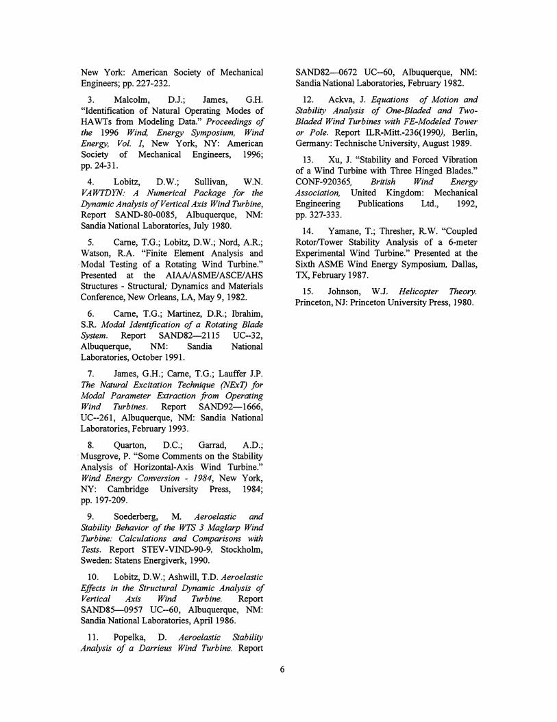
The first step in the postprocessing is the fixed coordinate transformation, i.e., transformation of azimuthally varying rotor periodic modes to a non-rotating coordinate system attached to the top of the flexible tower. The tower does not see rotor blades in isolation, but sees their cumulative effect, which . is best expressed in terms of rotor modes. Each blade mode of our four-bladed rotor corresponds to four rotor modes: a collective mode, a differential mode, and two cyclic modes. For illustration, consider the first lag modal component of the general response of each blade. Figure 2 shows the instantaneous position of the four blades resulting from oscillations in this mode. The amplitude and phase of this mode are usually different for each blade. Any arbitrary,displacement pattern of rotor blades, as shown in this figure, can be expressed as a superposition of four displacement patterns, which are depicted in Figures 3a through 3d. Figure 3a shows the rotor collective mode wherein all the blades oscillate in phase and with an identical amplitude. Figure 3b shows the rotor differential mode, sometimes called the scissors mode, in which alternate blades move out of phase, though with the same amplitude. The other two rotor modes, shown in Figures 3c and 3d, are called the cyclic modes wherein motion of one set of diametrically opposite blades either leads
i
or lags the other set of diametrically opposite blades by a phase of 90 degrees. As a result, the rotor e.g. (center of gravity) is offset from the hub center and whirls around it. The path traversed by the e.g. is generally an ellipse; it is a circle only if the amplitudes of oscillation of the two sets of alternate blades are identical. Figure 3c describes the rotor progressive mode, in which the e.g. rotates in the same direction as the rotor itself.· The speed of e.g. rotation is always higher than the rotor speed in this mode. Figure 3d describes the rotor regressive mode. In this mode, the e.g. whirls in a direction opposite to that of the rotor at low rotor speeds, but at hig�er rotor speeds it whirls in the same direction. However, in both cases; the e.g. whirl speed is lower than the rotor speed. For these reasons, the progressive mode is usually called the highfrequency cyclic mode and the regressive mode is called the low-frequency cyclic mode. As a consequence of fixed coordinate transformation, frequencies of the four-bladed rotor represent frequencies as see by an observer in the fixed coordinate system. These frequencies in general are different from each other. These are also different from the four individual blade frequencies as observed from the blade-attached rotating reference frames. In fact, the blade frequencies which are referred to the rotating frames vary with azimuth and, strictly speaking, cannot e�en be defined. Also note that, if there are N blades, there will be N rotor modes. Further, the differential mode exists only if there are an even number of blades.
Each flap mode would similarly result in four rotor modes (for the four-bladed rotor). In the collective flap mode, sometimes called the coning mode, all the blades flap in the same direction; in the differential mode, the blades flap 180° out of phase alternately. In the highfrequency progressive mode, the rotor disk wobbles in the same direction as the rotor angular rotation, whereas in the low-frequency regressive mode, the disk wobbles in the opposite direction. An excellent analytical treatment of the fixed coordinate transformation is provided by Johnson. 15
The system response, once transformed to the fixed reference frame, is Fast-Fouriertransformed to isolate the system coupled modal frequencies. A specialized modal identification technique is next used to identify system eigenvectors, which yield the coupled mode
3
shapes, and the eigenvalues, which yield the modal frequencies and dampings. The technique uses phase information to isolate coalesced modes should they occur.
RESULTS
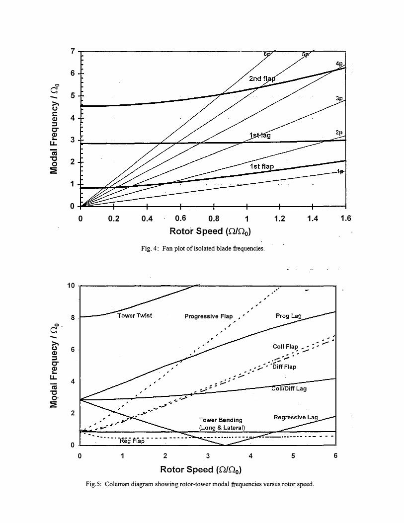
We first examine the isolated blade modes. The fan plot in Figure 4 presents the blade invacuum modal frequencies plotted versus the rotor speed normalized with respect to the nominal speed, Q0, of 1 Hz. The nonrotating bladefirst flap, frrst lag, and second flap frequencies are 0.83 Hz, 2.85 Hz, and 4.54 Hz, respectively.The frrst torsional frequency (not shown) is 16.85 Hz, too high to participate in the system modes of interest. As expected, the blade frequencies increase with rotor speed because of centrifugal stiffening. At the nominal rotor speed, the frrst flap, first lag, second flap, and frrst torsional frequencies become 1.47 Hz, 2.91 Hz, 5.28 Hz, and 16.88 Hz, respectively. If the plot were extended to the right, we would see the lag frequency curve intersecting the 1 p line around Q =3.5 Hz (lp stands for 1 times therotor speed). The lag frequency thus exceeds 1 p for rotor speeds below 3.5 Hz, and the rotor is accordingly termed stiff-inplane. Above 3.5 Hz, the lag frequency is below 1 p and the rotor is termed soft-inplane. Each mode actually involves coupling of flap, lag, and torsion motions because of blade twist and its crosssectional e.g. offset from the elastic axis. The designation of a mode simply indicates the dominance of a particular motion in that mode.
Figure 5 shows the variation of tower and rotor modal frequencies with rotor speed. A plot of this type is called a Coleman diagram. Unlike a fan plot, which shows the isolated blade frequencies with respect to the blade-attached rotating frame, a Coleman diagram shows the full system modal frequencies referred to a fixed (inertial) frame. Figure 5 presents frequency variation of three tower modes (lateral bending, longitudinal bending, and torsion) and the rotor modes associated with the blade first lag and first flap modes. As explained in the previous section, the first blade flap mode results in four rotor modes: collective flap, differential flap, progressive flap, and regressive flap modes. The frrst blade lag mode similarly results in four rotor lag modes. As seen, the frequencies of some modes vary . considerably with rotor angular speed; this depends on a complex

interplay of gyroscopic, centrifugal, elastic, and inertia forces. The corresponding rotor-tower mode shapes exhibit even more interesting vanatrons. A detailed examination of these mode shapes is not possible within the limited scope of this paper. We shall focus only on the frequency variations.
Consider the tower frequencies. The tower torsion mode frequency is 8.05 Hz when the rotor is parked. It increases with rotor speed because of the gyroscopic stiffening offered by the rotor disk. At high rotor speeds, the rotor attains considerable gyroscopic inertia and resists any changes in its plane of rotation. This restrains the rotor shaft motion in the horizontal plane and hence the tower twisting. The tower torsion motion is in fact strongly coupled with a rotor disk oscillation about a vertical axis passing through the hub center (the rotor disk actually wobbles, more so at higher rotor speeds). The designation 'tower torsion' only indicates the dominant motion; The tower lateral and longitudinal bending mode frequencies are close (indistinguishable in the plot) because the tower is tubular. The tower longitudinal mode is coupled with the rotor cyclic flap modes, whereas the tower lateral mode is mainly coupled with the rotor cyclic lag modes, particularly the regressive lag mode. The coupling between the tower bending modes and the rotor cyclic modes changes substantially with rotor speed, even though the frequencies, as seen in the figure, change little with the rotor speed. The coupling between the tower lateral mode and the rotor regressive lag mode particularly is quite sensitive to rotor speed (we shall get back to this when discussing Figure 6a).
Now consider the rotor flap modes. The differential flap mode frequency variation with rotor speed is identical to that of the isolated blade flap frequency variation (Figure 4). This is because the differential mode is a reactionless mode; it is not affected by the tower-deflectioninduced hub motion, and does not impose any net forces on the hub. The collective flap mode is somewhat coupled with the tower longitudinal mode and its frequency is a little higher than that of the differential mode. The frequency of the progressive flap mode, which involves wobbling of the rotor disk in the rotor rotation direction, is approximately 1p higher than the isolated blade flap frequency (1 p is the rotor rotational speed). It would be exactly 1 p higher if there were no
4
coupling from the tower motion. The regressive flap mode frequency, involving rotor disk wobbling opposite to the rotor rotational direction, is approximately 1 p lower than the isolated blade flap frequency.
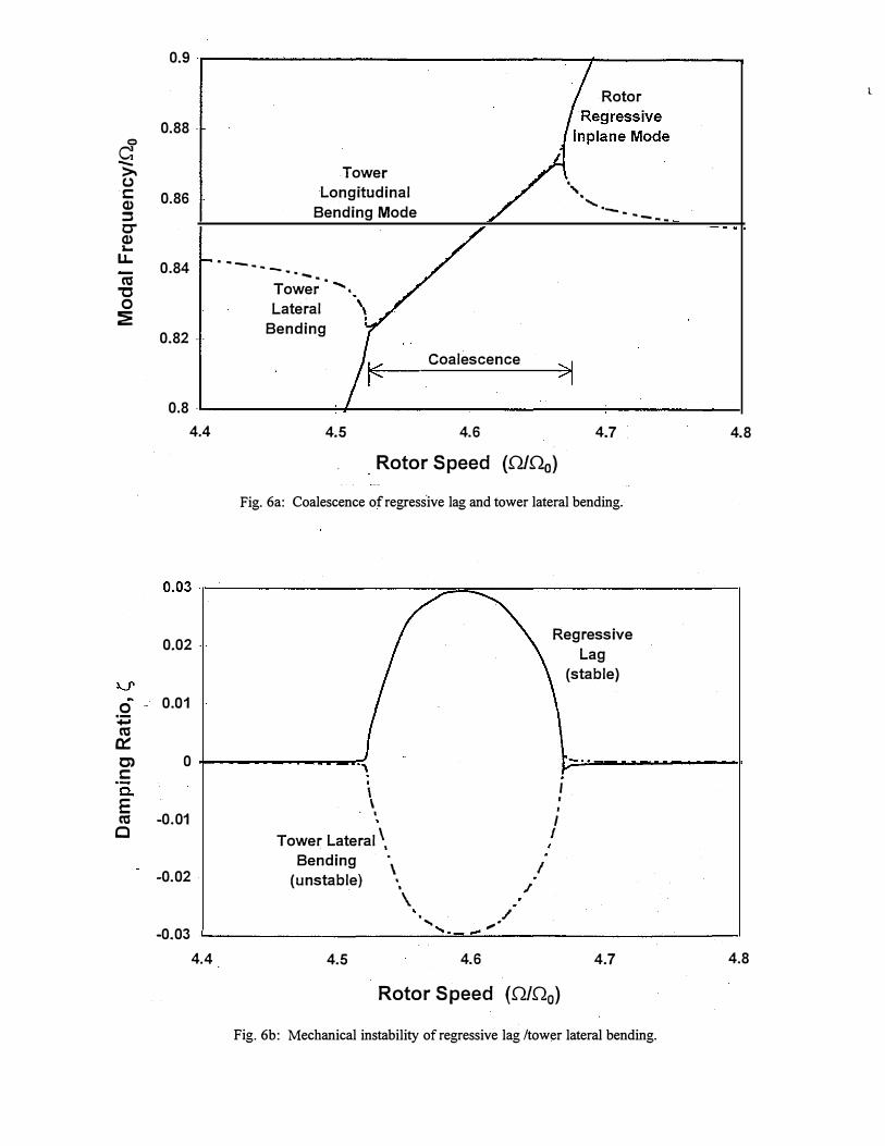
Finally we consider the rotor lag (inplane) modes. Frequency variation of the differential lag mode with rotor speed is identical to that of the isolated blade lag frequency variation (Figure 4). This is again because the differential lag mode is also a non-reactive mode. The collective lag mode frequency is very close to that of the differential; this would not be so if the rotor shaft were considered flexible. Frequency of the progressive lag mode is approximately 1 p higher than the isolated blade lag frequency. This mode involves high-frequency whirling of the rotor e.g. in the same direction as the rotor. The regressive lag frequency variation is rather interesting. When the rotor is stiff-inplane (Q < 3.5 Hz), the rotor e.g. whirls opposite to the rotor rotation and at a frequency 1 p lower than the isolated blade frequency. The e.g. whirl speed reduces as the rotor speed increases and falls to zero near n =3.5 Hz. At this transition rotor speed, the e.g. is offset from the hub center and does not rotate with the rotor. Above the transition rotor speed, the rotor becomes softinplane and the e.g. starts whirling in the same direction as the rotor and picks up speed as the rotor speed increases (this mode, therefore, is usually called the degenerate regressive lag mode). This whirl speed, however, always stays below the rotor speed. The regressive lag mode substantially couples with the tower lateral mode; this coupling is strongest in the vicinity of Q =4.6 Hz where the regressive lag frequency approaches the tower lateral frequency. In fact, this is where the instability occurs.
Figure 6a shows the Coleman plot zoomed in the vicinity of n =4.6 Hz. The tower longitudinal bending mode frequency stays unaffected since there is no mechanism that couples this mode with the lateral regressive lag mode. The tower lateral mode frequency, identified by the dashed-dotted line, however, tends toward the regressive lag frequency. Over a specific rotor speed range, the two frequencies in fact become locked. Even though we see a single frequency over this frequency-coalescence range, there are in fact two distinct modes. The rotor e.g. whirls in a perfect circle in both modes (outside this range, the e.g. whirl trace is generally an ellipse).

/ The amplitude of the rotor e.g. offset from the hub center, and that of the tower lateral motion, is the same in both modes. However, the phasing of the e.g. whirl witl1 respect to the tower motion is just the opposite in the two modes. This phase difference provides a mechanism wherein one mode continuously transfers energy to the other mode, resulting in a self-excited instability. One mode is damped and the other mode is unstable; this can be seen clearly in Figure 6b. The degree of instability depends on the inertial coupling between the rotor regressive lag mode and the tower lateral mode. Outside the coalescence range, the modal dampings are zero since no structural damping was assumed in the analysis.
Figures 7a and 7b show the effect of nacelle mass on the elastomechanical stability. The rotor speed is assumed fixed at 4.6 Hz for this plot. . As expected, both the tower modal frequencies reduce as the nacelle mass is increased. The rotor regressive mode frequency is unaffected, except over the coalescence range where it reduces somewhat with increasing nacelle mass.
Figures Sa and 8b show the effect of tower stiffuess on the elastomechanical stability. The rotor speed is again assumed fixed at 4.6 Hz. As expected, the tower modal frequencies increase as the tower stiffness is increased. The rotor regressive mode frequency is unaffected, except over the coalescence range where it increases somewhat with increasing tower stiffuess because of coupling with the tower motion.
Plots similar to Figures 7 and 8, plotted for different rotor speeds, help a designer to avoid nacelle mass and tower stiffness combinations that may result in a destructive elastomechanical instability.
CONCLUSIONS
A postprocessor has been developed that extends the capability of an existing simulation code (ADAMS) to predict system operating mode and stability. The ability of the postprocessor in identifying and quantifying the elastomechanical stability modes only has been demonstrated. However, it can be used with relative ease for aeroelastic stability analyses as well. Aeroelastic instabilities do not involve coalesc�nce and are therefore easier to analyze.
5
Results indicate that over a small rotor speed range around 4.6 Hz, the tower lateral mode and the rotor regressive lag mode coalesce, resulting in an elastomechanical self-excited instability. For a conventional turbine, this speed range is too high to be of concern to the designer. However, with the growing trend towards lighter, flexible, variable-speed wind turbines, and the potential for adaptive blades in future designs, such instabilities may very well fall within the design operating range and must be avoided through careful analyses and preventive design measures.
FUTURE WORK
Stability analysis based on the transient approach is feasible as demonstrated in this paper. However, it is quite time-intensive and requires considerable user interaction. The direct eigenanalysis approach, on the other hand, is usually extremely fast, accurate, and can easily capture higher modes. An attempt, in coordination with Mechanical Dynamics Inc., Michigan, is therefore already underway to examine the feasibility of upgrading ADAMS to yield wind turbine operating modes. Later, Floquet analysis will be introduced to handle periodic systems. Next, following development of transient dynamic inflow models and linearized aerodynamic models, aeroelastic stability analyses will be performed on selected wind turbines.
ACKNOWLEDGMENT
The work has been supported by the U.S. Department of Energy under contract number DE-AC36-83CHI0093.
REFERENCES
I. Elliott, A.S.; Wright, A.D. "ADAMS/WT: An Industry-Specific Interactive Modeling Interface for Wind Turbine Analysis." Proceedings of the 1994 ASME Wind Energy
Symposium, Wind Energy-1994, SED-Vol. 15, New York: American Society of Mechanical Engineers; pp. 111-122.
2. James, G.H. "Extraction of ModalParameters from an Operating HA WT using the Natural Excitation Technique (NExT)." Proceedings of the 1994 ASME Wind Energy Symposium, Wind Energy-1994, SED-Vol. 15,
New York: American Society of Mechanical Engineers; pp. 227-232.
3. Malcolm, D.J.; James, G.H. "Identification of Natural Operating Modes of HA WTs from Modeling Data." Proceedings ofthe 1996 Wind, Energy Symposium, Wind Energy, Vol. I, New York, NY: American Society of Mechanical Engineers, 1996; pp. 24-31.
4. Lobitz, D.W.; Sullivan, W.N. VA WTDYN: A Numerical Package for the Dynamic Analysis of Vertical Axis Wind Turbine, Report SAND-80-0085, Albuquerque, NM: Sandia National Laboratories, July 1980.
5. Carne, T.G.; Lobitz, D.W.; Nord, A.R.;Watson, R.A. "Finite Element Analysis and
·Modal Testing of a Rotating Wind Turbine."Presented at the AIAA/ ASME/ ASCE/ AHS Structures - Structural; Dynamics and Materials Conference, New Orleans, LA, May 9, 1982.
6. Carne, T.G.; Martinez, D.R.; Ibrahim,S.R. Modal Identification of a Rotating Blade System. Report SAND82-2115 UC--32, Albuquerque, NM: Sandia National Laboratories, October 1991.
7. James, G.H.; Carne, T.G.; Lauffer J.P.The Natural Excitation Technique (NExT) for Modal Parameter Extraction from Operating Wind Turbines. Report SAND92-1666, UC--261, Albuquerque, NM: Sandia National Laboratories, February 1993.
8. Quarton, D.C.; Garrad, A.D.; ·Musgrove, P. "Some Comments on the StabilityAnalysis of Horizontal-Axis Wind Turbine." Wind Energy Conversion - 1984, New York, NY: Cambridge University Press, 1984; pp. 197-209.
9. Soederberg, M. Aeroelastic and Stability Behavior of the WTS 3 Maglarp Wind Turbine: Calculations and Comparisons with Tests. Report STEV-VIND-90-9, Stockholm, Sweden: Statens Energiverk, 1990.
10. Lobitz, D.W.; Ashwill, T.D. AeroelasticEffects in the Structural Dynamic Analysis of Vertical Axis Wind Turbine. Report SAND85-0957 UC--60, Albuquerque, NM: Sandia National Laboratories, April 1986.
11. Popelka, D. Aeroelastic Stability Analysis of a Darrieus Wind Turbine. Report
6
SAND82-0672 UC--60, Albuquerque, NM: Sandia National Laboratories, February 1982.
12. Ackva, J. Equations of Motion andStability Analysis of One-Bladed and TwoBladed Wind Turbines with FE-Modeled Tower or Pole. Report ILR-Mitt.-236(1990), Berlin, Germany: Technische University, August 1989.
13. Xu, J. "Stability and Forced Vibrationof a Wind Turbine with Three Hinged Blades." CONF-920365, British Wind Energy
Association, United Kingdom: Mechanical Engineering Publications Ltd., 1992, pp. 327-333.
14. Yamane, T.; Thresher, R.W. "CoupledRotor/Tower Stability Analysis of a 6-meter Experimental Wind Turbine." Presented at the Sixth ASME Wind Energy Symposium, Dallas, TX, February 1987.
15. Johnson, W.J. Helicopter Theory.Princeton, NJ: Princeton University Press, 1980.
Build Wind Turbine Model
(AD AlVIS)
FFT
Rev Up Rotor
to Desired Speed
Identification Technique
Impart Forces to Excite Desired
Modes
Fig. 1: Response-based stability analysis approach.
(
l
I I
i__ _.. __ .,.,..,.,.,..-- I
/ . / I/ .
/ I I '
..... ..... ..... ' ' '\
\ \
\ \ \ \ ---1------ _____ J __
\ \ \ \ \
\ '\
' ' ' ..... ..... ..... I """"/ . .,... - -l-- ---i
/
Fig. 3a: Rotor collective lag mode.
I I
I /
l
I I
I I
I
2 !
.... --- r -
.,... . /
"" I/ .
/ I I ,
3--1------
\ \
'\ '\ ', I ' . '""' ........ --L-
! 4
..... .....
.,... .,...
..... ' ' '
\ \
\
l ------r-- 1I
/ /
/
I I
/
I I
I
Fig. 2: Rotor general lag response (resulting from the motion of blades in the first lag II10de)
I I
I I
I
! .,.,.,..---- r -
.,... . /
"" I / . / I I '
..... .....
--1------
\ \
\ '\ ' ' ..... ..... .....
. /
-L--_...,. !
' ' ' '\
\ \
\
\ ------J---
/ /
/
1 I
I I
I I
/
Fig. 3b: Rotor differential lag mode.

Q - I - ...... � ...- ' / ' ' / I ' / ' \ I I \ I , \ I
I ' -
Time= 0 arT
I I
I
' \ \
Rotor e.G. moves anticlockwise �
---/
- ...... '
/,_
----- �-
/ '
/ / ' '\
'\ ' '
T = T 4
I I
\ \
L - - • 1 f \ , I \ ! I
\ I I '\ ' / , I /.
' ' / ....... I �
T 2
Fig. 3c: Rotor progressive lag mode.
�--
............ , '
'\
3T 4
/ /
\ \ '
I I
I /
Q �,_---/
I I
I '--�
...... ' '
Time= 0 arT
'\ \
\ ' I
Rotor e.G. moves clockwise G
' / ·--,.,...
T T=-4
/
I I
I /
(__ ·-1 I \ , I \ ! I
\ I I '\ ' / ' , , /
' ' / ....... I ' /
T 2
Fig. 3d: Rotor regressive lag mode.
/,_
...--- ,-
/ '
I I
I
' \
\ '\ ' '
..................... _.
3T 4
......
...-
' .,
/ /
'\ ' \ \
I I
I /
0
c ->. 0 s::::: (I) ::l C" (I) �
u. ns
""C 0
:E
7
6
5
4
3
2
1
0 0 0.2 0.4 0.6 0.8 1
Roto·r Speed (.Q/.00)
Fig. 4: Fan plot of isolated blade frequencies.
1.2 1.4 1.6
o-
C ->. (.) (I) ::l C" (I) �
u. ca
'"C o-
:1:
10 -�--------------------��----------------------------�,. .. ·
6·
4 ;
.... 2
. .
Progressive Flap ;
" " " "
" ........ Coli Flap .. .. = .. .. ...... . ..
. � .. ,:;, . ,. .,. ..
.. ;.." • ·oiff Flap .... · ..
........ ....
.. ;..-... . .. .. : :. �
.. � oii/Diff Lag
•. • • • • • • "R:eg �f'ap • · • · � • • • • • • 0 -�------���----�--------���--�-------------------�
0 1 2 3 4 5 6
Rotor Speed (.Q/.00) Fig.5: Coleman diagram showing rotor-tower modal frequencies versus rotor speed.
0 .9 ·r---------------------l'----------.
Rotor 0 .88.
0
c -� Tower (.) ·, s:::: 0 .86 Longitudinal . Q) ..... Bending Mode ·-:::l - -
C"' Q) J..
u. 0 .84 . .. __ .. .. ..... . .
ca - . . "C Tower '· 0 Lateral � Bending
0 .82 .. Coalescence
>I 0 .8 .
4 .4 4 .5 4 .6 4 .7
Rotor Speed (nino)
Fig. 6a: Coalescence of regress-ive lag and tower lateral bending.
---
4 .8
0 .02 .
0 .. - 0 .01 +I ca
� C) 0 �--..-....... ....-........... � s:::: 0.. E ca -0 .01
0
-0 .02
\ \ . '
Tower Lateral \ Bending
(unstable) \ . . \
·.... /
/ I
Regressive Lag
(stable)
. I r r
I I
-· ·
,. . -0 .03 -L---------------------------------------------�'�-�-�------------------------�--------------------�
4 .4 4 .5 4 .6 4 .7 4 .8
Rotor Speed (0/00)
Fig. 6b: Mechanical instability of regressive lag /tower lateral bending.
t

0
c:->.(.J t: Q) ::::1 0"'Q) I..
LL
1.1
1 . ' ' '
Tower Lateral ' ,Bending
0 .9
Regressive Lag
0 .8 '.
Coalesce11ce
0 . 7 -L ----�----�------�----�----------------�----�
5 0 0 0 60 0 0 7 0 00 800 0 9 0 0 0 10000 110 0 0 12 0 0 0 13 0 00
Nacelle Mass {lb)
Fig. 7a: Effect of nacelle mass on coalescence of :frequencies.
V' 0
� ctS0::: 0) t: a. EctS
0
0 .04-
0.0 3 . ..
0 .02 '.
0 .01
0
-0.01
-0.02
-0.03
-0.04
sooo· 6000 7 000
{Q/Q0 = 4.6)
Regressive Lag (stable)
\
Stable
/� I·
w Unstable I
I I
Tower Lateral\ / Bending \ /
(unstable) ·...., / . .. """
8000 9 000
'·--
10000 11000 12 000 13 000
Nacelle Mass {lb) Fig. 7b: Effect of nacelle mass on damping ratio.
,-, ri
.

0
c ->-(.) s::::: (1) :J 0" (1) I-
u..
1 .
0 .95 --
0 .9
0 .85
0 .8
0 .75 ..
0 .7 .
0 .65 · , 0 .6
Regressive Lag
Coalescence
0 .7 0 .8 0 .9 1 1.1
Tower Stiffness/Nominal Stiffness Fig. 8a: Effect of tower stiffuess on coalescence of frequencies.
1.2 1.3
0
0 .02._:.
0 .01 . -
Regressive Lag (stable)
Stable
!i\ 0 1------------c:---·-· ----·--------+----·.
-0 .01 . .
-0 .02
-0 .03
0 .6 0 .7
... , \V Unstable
\ '
Tower Lateral \ Bending
(unstable)
0 .8 0 .9
'
\ .
\ .
-- ,. ...
1
I
I '
'
I '
/ . .
1.1
Tower Stiffness/Nominal Stiffness
Fig. 8b: Effect of tower stiffuess on damping ratio.
1.2 1.3