Embed Size (px)
Citation preview
Automatica, Vol. 10, pp. 495-506. Pergamon Press, 1974. Printed in Great Britain.
Stability Analysis and Design for Aircraft Gust Alleviation Control*t
Analyse de Stabilit6 et Conception pour le Contr61e d'All6gement de Bourrasque d'Avions
Stabilit~itsanalyse und Entwurf f'tir die Regelungzur Milderung des Einflusses von Windb/Sen auf ein Flugzeug
Ana~in3 yCTO~qHBOCTH H pac~ieT ca~o:ieTrimx cncl~eM ynpaB~terirI~ ~0-[g KOMr[eHcatIHH BeTpOBblX H a r p y 3 o r
P. N. N I K I F O R U K , M. M. GUPTA and K. KANAI+ +
Stability analysis indicate the need for an on-line, two-level, adaptive gust alleviation control system for a high speed aircraft operating in an unknown environment.
SummAry--This paper is concerned with the stability analysis and the development of an on-line two-level gust alleviation control system for a high-speed aircraft operating in an unknown environment. As is well known, such an aircraft experiences dynamic instability in its lateral motion when subjected to the longitudinal and lateral gusts. This is due to the phenomenon of lateral-longitudinal aerodynamic cross-coupling.
In the first part of this paper the instability behaviour, in the presence of a longitudinal gust, of two typical high-speed aircraft is analyzed. From theoretical and simulation studies it is shown that for a sinusoidal gust, and for a given con- figuration, the instability region is a function of both the amplitude and frequency of the gust disturbance.
In the second part of the paper, an on-line gust alleviation control system is synthesized for such an aircraft operating over a wide range of unknown environmental conditions. This control system employs a two-level control structure. The controller, however, does not require an explicit know- ledge of the aircraft parameters or the environment. Typical simulation results are presented which verify the theoretical predictions.
1. INTRODUCTION
1.1 General
Tim design of a gust alleviation control system which can cope with the instabilities that occur in
* Received 27 December 1972, revised 5 September 1973, revised 7 March 1974. The original version of this paper was presented at the 5th IFAC Symposium on Automatic Control in Space, held at Genova, Italy, 4--8 June 1973. It was recommended for publication in revised form by Associate Editor P. Parks.
t This work is supported by the National Research Council of Canada under Grants A-5625 and A-1080, and the De.fence Research Board of Canada under Grants 4003-02 and 9781-04.
~: Systems and Adaptive Control Research Laboratory, Department of Mechanical Engineering, University of Saskatchewan, Saskatoon, Saskatchewan, Canada.
the lateral and longitudinal modes of modern high- speed aircraft is a complicated and difficult problem [1, 2]. The normal and usual approach in the design of such a system is to first establish a linearized model of the aircraft [1]. Once this is done, con- ventional control theory, either classical or modern, is then used for the design of the control system [1-3].
An inherent requirement [2, 3] of these con- ventional control techniques is that of identifying the plant parameters, and measuring the state variables. Not only are these difficult tasks, in most instances, but they become almost impossible in the case of on-line control for a high-speed aircraft operating over a wide range of unknown environ- ments. For this reason on-line adaptive type control techniques which can preclude these rigid requirements are desirable [6].
The first part of this paper is concerned with the stability analysis of the lateral dynamic motion of an aircraft subjected to a sinusoidal type longi- tudinal gust. In this analysis the stability boundaries, shown in the amplitude-frequency plane of the sinusoidal gust, are first predicted theoretically and then verified using simulation studies for two types of aircraft configurations. This is then followed by the design of an on-line gust alleviation control system employing a two- level control structure [6]. It is shown that this design procedure does not require an explicit knowledge of the aircraft parameters or the gust acting upon it. Further, as will be shown later, it essentially bypasses the rigid requirements o f identification and state variable measurements as required by the existing techniques.
495
496 P .N. NIKIFORUK, M. M. GUPTA and K. KANAI
1.2. Perturbation equation of lateral motion due to longitudinal gust
In this section the stability of two high-speed aircraft subjected to a longitudinal gust is studied. For this purpose the usual aerodynamic assump- tions that lead to the decoupling of the aircraft equations for small perturbations in the motion into lateral and longitudinal sets are made [1, 3]. It is also assumed that the various elements of the input disturbance vector which are associated with the different components of the gust are uneor- related. On this basis the linearized small pertur- bation equation for the lateral motion of such an aircraft subjected to a longitudinal gust, g(t), and lateral gust, vg(t), is derived in Appendix B, equation (b-l). The corresponding state evolution equation in a normalized form is given by
fc(t)=A(g(t), t)x(t)+ Bu(t)+G(va(t), t) (1.1)
where the states x(t)A[[3(t), dp(t), p(t), P(t)]'eR*, and the control u(t)A[3a(t), 6r(t)]'eR 2.
It is known that the important stability deri- vatives of the matrix A are functions of the lift coefficient, C~, where Ct may be written in the small perturbation form [1,5].
some results have been reported by ICHIKAWA and KANAI [7] for the stability analysis of higher-order linear systems with sinusoidally time-varying parameters. This method is based upon a successive approximations technique and yields a simple stability criterion. As explained in Appendix D. the method assumes a strong low-pass filtering effect in the system. For the system considered in this paper, the dynamic equations for the lateral motion possess, we believe, sufficient low-pass filtering characteristics to employ this successive approximation method of Ichikawa and Kanai.
For the sinusoidal gust disturbance g(0 is
g(t)=esin vt, e,~ 1. (2.1)
The perturbed lift coefficient in (1.2) then becomes
Ct(t)=Cto(1 +ssin vt). (2.2)
The corresponding equations for the lateral and Dutch roll motions are given in (1.3) and (1.4). For input forcing terms equal to zero; that is, for u(t)=vg(t)=O, these equations become respectively
Cz(t)=Cto[1 +g(t)] , ]g(t) I ,~ 1 (1.2)
where Czo is the nominal value of the lift coefficient, and g(t) is the longitudinal gust.
As shown in Appendix B, the lateral motion of the aircraft, equation (1.1), may equivalently be written as
.~(t) = {A o + Agg(t)}x(t) + Bu(t) + Gv,(t) (1.3)
where Ag is an equivalent perturbation matrix on A due to gust g(t), and matrix G represents the aircraft input matrix for the lateral gust, %(0.
The state evolution equation of the normalized perturbation equation for the Dutch roll motion, which is derived in Appendix B, is written as
~(t) =(Ao + Agssin vt)x(t) (2.3)
5cd(t)=(Ado+ Ad,esin vt)x~(t). (2.4)
In order to apply the stability boundary criteri on of Appendix D to (2.3) and (2.4) these equations must be transformed into the phase canonical form. This transformation is given in Appendix B and the respective equations are
~(t)=(Fo + F~sin vt)z(t) (2.5)
2d(t)----(Fdo + Fdgssin vt)zd(t) (2.6)
5¢ d(t ) = {AdO +.4 dgg(t) }Xd(t ) + BdUd(t )
+ G~vg(tt) (1.4)
where Fo, F v Appendix B.
F~o and F~g are defined in
where the state xd(t)A[fl(t), P(t)] 'sR 2 and control u~(t)Arr(t)eR 1.
the
2. STABILITY ANALYSIS OF LATERAL DYNAMIC MOTION
There is no general method available for the study of the stability behaviour of systems of the ype considered in this paper. Re cently, however,
Simulation studies
Two separate sets of stability derivatives wore studied. The first corresponds to a hypothetical delta wing supersonic transport aircraft (~1) during low speed operating conditions, the second corresponds to a hypothetical subsonic interceptor ~2). The parameters of these aircraft are tabulated in Appendix C.
Stability analysis and design for aircraft gust alleviation control 497
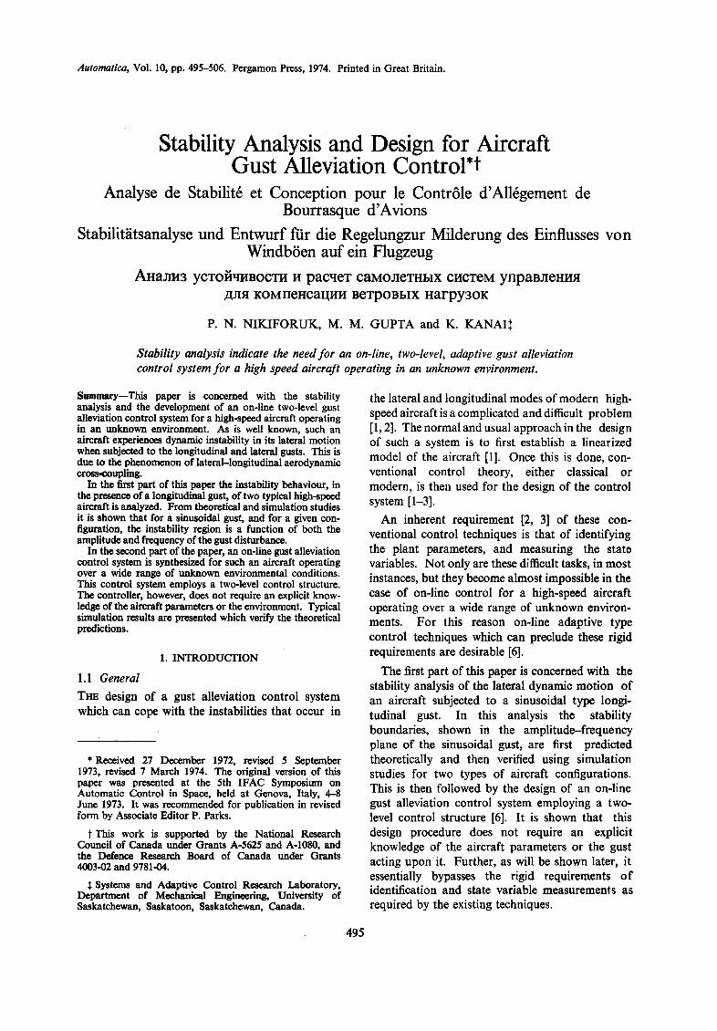
Figures l(a)-3(a) show the theoretically com- puted boundaries of the stability region in the
I ~ o ~ F~RST APPROXIMATION AT
. . . . UNSTABLE/~ A : : O } . . . . . . . . . .
i 05 ~ " ; 0 STABLE
~ 0 0 * ~ STABLE * UNSTABLE |
2 4 6 8 io
u ( RAD./SEC.]
(0 ) THEORETICAL STABILITY BOUNDARY IN ( - u PLANE FOR get)--'-- (SIN v t
( , 0 4 , V .35 ~ , 0 . 4 , ~ , 5 ~ E, 0.4, v , L5 " i
RUDDER ~ 2 0 V - - - - R U D D E R B O Y - - - SteP ~ - - ~-~. . . . . . step ~-[~---~ [
I RUODER 20v r- - -
STEP ~ `j '
- IO' 1 " SECONDS
, s , , , _ f # j ~ , ~ ' ,s .... I~I, ' S ' " " I 1 ¢ I - - ( SIN ~/t (STOP) ~ ( SIN Vt (STOP) ~ ~ SIN 7/t (STO p` \ '
STABLE UNSTABLE STABLE
(b) SIMULATION RESULTS { IOOV = I rod )
F r o . 1. Stability studies for lateral dynamic motion of supersonic aircraft No. 1.
*.0
o B ~I
AB / FIRST APPROXIMATION AT
~ 2
ANA~S SIMULATION
o o o ~ ; / ~ ¢ ~ 0 o STABLE 0 0 0 • 0 • UNSTABLE
o ~ j ' s TABLE
I I I t I.O 2.0 3.0 4.0
~ ( R A O . I S E ¢ . )
I B,O
(o ) " THEORETICAL STABILITY BOUNDARY IN ( - v PLANE FOR ~ ( 1 ) * E SIN lot
T l ' ° r SEc°Nos IOOV t AAJIAIAAAAIA|JJ. -E S*N 7/t VVVVVVVIIV'/qVVV
-11- ~ * 0 . 5 , F • 1.2(RAD/SEC.} ~ * 0 .5 t V • 1.9 (RAD.ISECJ 30V I ~ V * t
, ~ t , . _ _ L__ . ^ , ^ n A l ~ l l l ~, y ~ - - ~ , -v,,,,vuV~ ~
STARLE UNSTABLE - t - - t -
l i t I I I I U I I I I U I U U | I | I i l I I i I I J I | | U I I I I j I U U | | I j
~lH]l~l l l f l1111]]gl f f lHl l l l l l l i t l t lHI l l l l U
T ' ( • 0.B, :s, 1.3 ( ~ 0 . / s i c . } T ( • 0.5, v • 2.1 (RAD.ISE0.I
. ~ ,~v AAA~^,,^^, I ^ ~ ~.A A ~ I ~ A I L _ - " ~ , ' , - v v V.v v v v v ),, U~UVvv . . . . . . .
UNSTABLE STABLE " t - " t -
# . , v v v v ~ v v v ~ ' , .~ j~Vvv . . . .
( b ) SIMULATION RESULTS
( l O O V = I r a d )
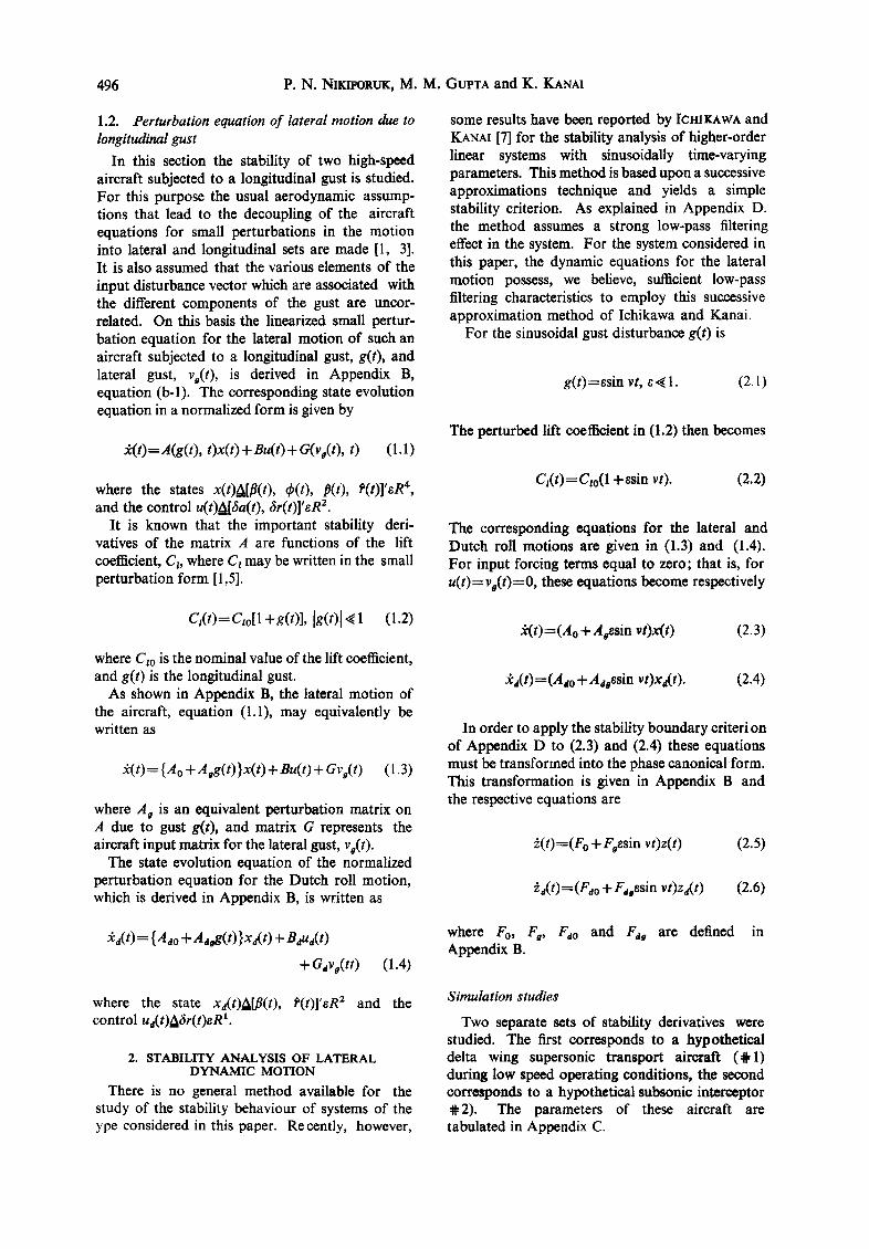
FIe. 2. Stability studies for Dutch roll motion of super- sonic aircraft No, 1.
ANALOG SIMULATION 0 STABLE • UNSTABLE
l ° ° o % : / . ; ; , , o o 0,5 FIRST APPROXIMATION "~ - / / . ~ . . . . .
. . . . . . . -v ............ Y ~ sTABLE AT ~ " Z
I I I I t 1.0 2JO 3,0 4.0 S,O
m. f/ (RAD./SEC.)
(O) THEORETICAL STABILITY BOUNDARY IN ( - ~ PLANE FOR. g ( t ) - iE SIN Ist
, y v ~,~ ~_ ,o,~ uAIAA, . . . . . . ~u~ . . . . . . . . . . P l , ~ r ' - --- ~ J " " " " . . . . . . . . . . . . . . . . .
EI~V ulAAAAaa*l, A**., . . . . . . . . . ~" ~ I ' 11 | I I~lwvv~t . . . . . . . . . .
"t"-- r-" ~ v ~ , , , . . . . . . . . . . . . . . . .
2OV . . , . . . . . . . . . . . . . .
IOOV AAAAAAAAA|AAAA A G SINI/t Imu.m.wm,~mwm.~, ,~,- , . , . , ,~ SIN s,t VVVWVWVVVWW (.O.B,V. ' .S(RAO.;S'~!
E. 0,6,;I/• 1,0 (RAD,/SEC.)
-~" ~V Inu... _ t
'-r"
~'- 7 - . , , ~ s vqF,dlz~.-
~ lip' . . . . . • -(-- " I " ~ 1 0 0 V ~
.E BIN Ft m E SIN l i t
(E,GBIi l t ,E. I ' ( ' O . S , V ' I . 8 ( l O . I , i tmlJ I (RAO,/SEO.) (flAO.4[C.)
UNSTABLE STABLE
t ,b ) S I . M U L A T I O N R E S U L T S
( l O O V = l r o d )
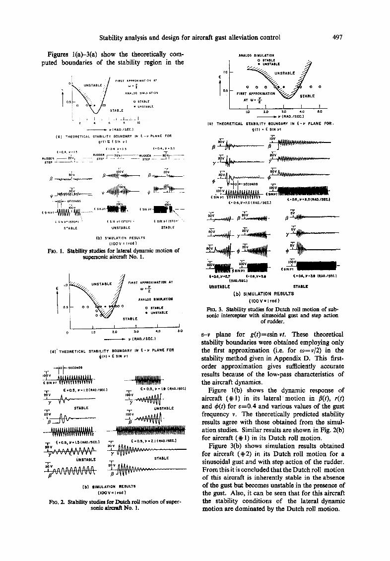
FEe. 3. Stabi l i ty studies for D u t c h rol l m o t i o n o f sub- sonic intercepter with sinusoidal gust and step action
of rudder.
8-v plane for g(t)=Bsinvt. These theoretical stability boundaries were obtained employing only the first approximation (i.e. for re=v/2) in the stability method given in Appendix D. This first- order approximation gives sufficiently accurate results because of the low-pass characteristics of the aircraft dynamics.
Figure lib) shows the dynamic response of aircraft (@1) in its lateral motion in #It), r(t) and ~b(t) for 8=0.4 and various values of the gust frequency v. The theoretically predicted stability results agree with those obtained from the simul- ation studies. Similar results are shown in Fig. 2(b) for aircraft (@ 1) in its Dutch roll motion.
Figure 3(b) shows simulation results obtained for aircraft (~2) in its Dutch roll motion for a sinusoidal gust and with step action of the rudder. From this it is concluded that the Dutch roll motion of this aircraft is inherently stable in the absence of the gust but becomes unstable in the presence of the gust. Also, it can be seen that for this aircraft the stability conditions of the lateral dynamic motion are dominated by the Dutch roll motion.
498 P .N . NIKIFORUK, M. M. GUPTA and K. KANAI
Although the results for the stability studies were obtained assuming a sinusoidal gust, g(t)=esin vt, the design of the gust alleviation control system, as given in the following section, is applicable to a wide class of random gust phenomenon.
3. DESIGN AND IMPLEMENTATION OF A GUST ALLEVIATION CONTROL SYSTEM
A controller synthesis technique for a class of unknown plants operating in an unknown environ- ment which forces the plant to follow a given set of desired response characteristics, and which yields a Lagrange stability of the closed-loop system, is described in [6]. The controller employed has a two- level structure, a feedforward controller on its first-level and a conditional feedback controller on its second-level. The design procedure employed is the Liapunov signal synthesis technique. In this approach a mathematical model of the plant, based upon certain input/output operating conditions, is first formulated. The first-level controller is then synthesized for this known model so as to satisfy certain desired response characteristics. This is followed by the synthesis of the second-level controller which provides conditional feedback. It is a function of the measured error between the model output and the plant output, and the characteristic vector, 2(0, which is characteristic to the unknown environments of the plant. This control procedure, as we mentioned earlier, does not require an explicit knowledge of the plant dynamics or its environment, and it thus bypasses the need for identifying the state variables as required by modern control theory.
In this section the design procedure for this controller is first described. Some typical simul- ation studies which were carried out are then presented using aircraft ( ~ 1) as an example. In particular, the lateral motion of this aircraft is described when it is subjected to random lateral and longitudinal gusts.
The general equation of this type of aircraft in a state evolution form is derived in Appendix B and is
£¢(t) = [.4 o + A gg(t)]x(t) + Bu(t) + Gvo(t ). (3.1)
The corresponding numerical values are given in Appendix C. The response characteristics of interest of this aircraft are given by
where
y(t)=Cx(t) (3.2)
[:oo 0] c = 0 0 , y(0~La(t) , ~(0]' .
A general structural form of the gust alleviation
control law may be written as
u(t)=f,(y(t), yrn(t), Urn(t), 2(0, r(t), t} (3.3)
wheref,{v} is, in general, a nonlinear time-varying function of its arguments and urn(t)eR"% the first- level control, r(t)eR r is a vector of pilot command inputs, 2(t)eRrn is a vector characteristic to the aircraft operating in an unknown environment. The design procedure for Um(t ) and u(t) will now be described.
The design of the first-level controller For the design of the first-level controller a
characteristic model representing the nominal Dutch roll motion will be assumed to be
~rn(t) = Amxm(t ) + Bmum(t ) (3.4)
with desired response characteristics
yrn(t)=Xm(t) (3.5)
where, for aircraft @ 1
Am=Ado= I -O'O057 -1 1 0.065 -0"057 '
Brn=Bd=[ 0.0015"] - 0.0034 J
and urn(0 is a linear feedback control law given by
Um(t)=F,,xrn(t)+ F,6,(t)
6,(t)Ar(t), the pilot command input. (3.6)
Equation (3.4) represents the motion of the model in its Dutch roll motion, and it is assumed that the desired handling qualities of the controlled aircraft model (3.4) is given in terms of natural frequency con and damping ratio (. Based upon the pilot iso-opinion curves [3] the following assignments* are assumed for simplicity
(=0 .2 , con= 1.0 rad/sec. (3.7)
Using the canonical controller synthesis technique [9] and performing the appropriate numerical calculations.
F , ,= [ -264 , - 19], F,=L (3.8)
* In general, for the purpose of achieving certain deaign objectives which are defined for Dutch roll response as desirable handling quality, the d~irable aircraft responses to lateral control inputs might tm spocitiod in the criteria for roll rate oscillations.
Stability analysis and design for aircraft gust alleviation control 499
The design of the second-level controller For this purpose, the aircraft tracking error,
e(t), is defined as
e(t)=ym(t)-y(t), e(t)~R 2. (3.9)
The error differential equation is given by
i(t)=A,e(t) + B,,u,(O + 2( t ) - Dou(t) (3.10)
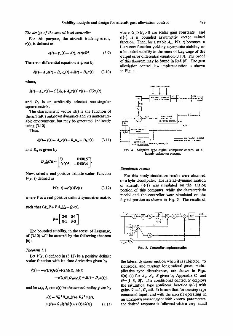
where GI >-G2>0 are scalar gain constants, and ~k{.} is a bounded asymmetric vector valued function. Then, for a stable Am, V(e, t) becomes a Liapunov function yielding asymptotic stability or a bounded stability in the sense of Lagrange of the output error differential equation (3.10). The proof of this theorem may be found in Ref. [6]. The gust alleviation control law implementation is shown in Fig. 4.
where,
2(t)=Amx(t)- C{Ao + Aag(t)}x(t)- CGva(t)
and Do is an arbitrarily selected non-singular square matrix.
The characteristic vector 2(t) is the function of the aircraft's unknown dynamics and its unmeasure- able environment, but may be generated indirectly using (3.10).
ThUS,
2(t) = d(t) - A,e(t) - Bmu,, + Dou(t) (3.11)
and Do is given by
D°ACB= ~0"005 0"0015"] -- 0-0034 j"
Now, select a real positive definite scalar function V(e, t) defined as
V(e, t)=e'(t)Pe(t) (3.12)
where P is a real positive definite symmetric matrix
such that (A" P + PAm)A-Q <O,
O ' l P= 0"1 3"0 "
The bounded stability, in the sense of Lagrange, of (3.10) will be assured by the following theorem [6]:
Theorem 3.1 Let V(e, t) defined in (3.12) be a positive definite
scalar function with its time derivative given by
f'(t)=-e'(t)Qe(t)+ 2M(t), M(t)
=e'( t)P[ D,u,,( t) + 2(t)- Dou( t)],
and let u(e, 2, t)=u(t) be the control policy given by
u(t) ffi l)o' e .u . ( t ) +Do luc(O,
uc(t) fG12(t)~/{G2e'(t)pR(t)} (3.13)
BUST {UNMEASURABLE)
I l l i xCt) i ly(t)
AIRCRAFT OYNAMIDII MEASUREMENTS ~ (LAAGELY UNKNOWN) ~ ' l
IU(k )
E~ . . . . . . CONTROLLER (z~d LEVEL CONTeOL) i ~ _ ~ .
- - /
I Ym tk}
: . I 0 - , , , , , , , 0 1 _ . . . . . . . . . . . . . . . J e- - - I um(k) uoD[,,. "[ I I 1 1/ . . . . . ~,.~I__REF,, meure, r(k) ~ CONTINUOUS SIDNALS I . . . . . ~ CONTROLLER . . . . DISCRETE $1tlNAL$
• ( I l l LEVEL CONTROL)
F[o. 4. Adaptive type digital computer control of a largely unknown process.
Simulation results
For this study simulation results were obtained on a hybrid computer. The lateral-dynamic motion of aircraft (~=1) was simulated on the analog portion of this computer, while the characteristic model and the controller were simulated on the digital portion as shown in Fig. 5. The results of
FIG. 5. Controller implementation.
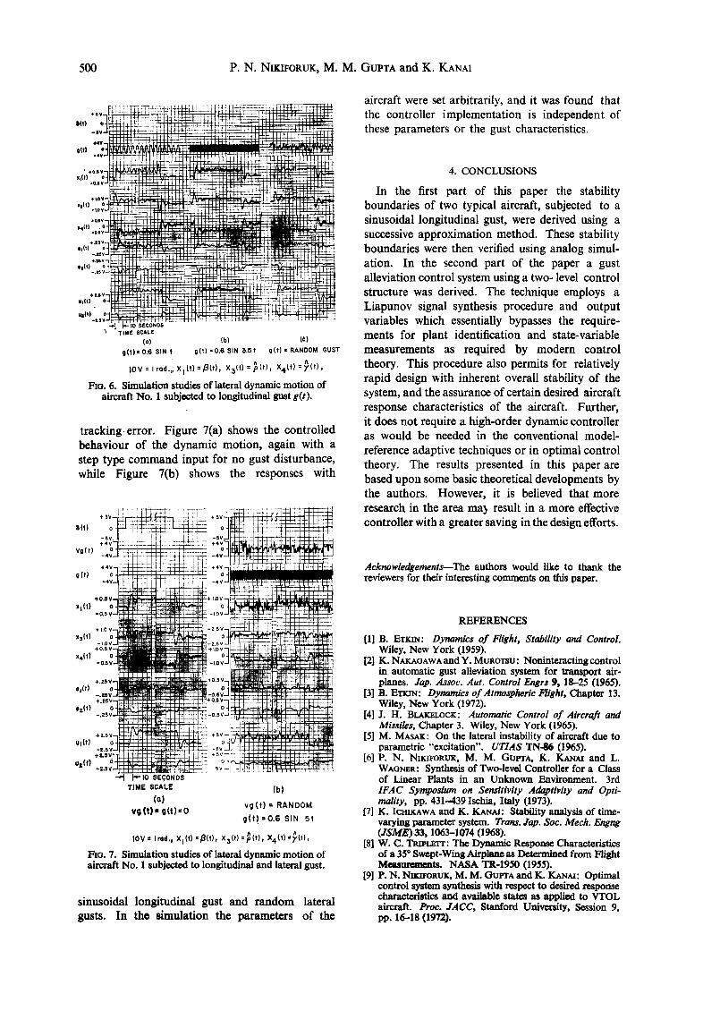
the lateral dynamic motion when it is subjected to sinusoidal and random longitudinal gusts, multi- plicative type disturbances, are shown in Figs. 6(a)-(c) for A0, Ag, B given by Appendix C and G=[1, O, 0]'. The conditional controller employs the saturation type nonlinear function ¢{.} with gains GI=I , G2=8. It is seen that for the step type command input, and with the aircraft operating in an unknown environment with known parameters, the desired response is followed with a very small
500 P . N . NIKIFORUK, M. M. GUPTA and K. KANAI
, , "3?
,7 • ¢o.sv gl(t) .O.S V~
xslt) -i.e
x4(t| -o.sv~
+ , t S V . , , , . . ,o 3 . 'L
==ill÷ | ' 6~
ut(t) o-t~'~ct+~,_ :". " +~-
3 TIME SCALE to) (b) (C)
gEt)" O.6 SIN t get) =0.6 SIN 5.5t gEt) • RANDOM GUST
1OV= l rod . , .X l ( t )= f l ( t ) , X3(t} =~ ( t ) , X 4 t t ) = ~ ( t ) ,
FIG. 6. Simulation studies of lateral dynamic motion of aircraft No. 1 subjected to longitudinal gust gEt).
t racking error. Figure 7(a) shows the controlled behaviour of the dynamic motion, again with a step type command input for no gust disturbance, while Figure 7(b) shows the responses with
Bit)
vo(t)
q l t )
xt(t)
x:(t)
x,(t)
e,tt)
e=(t)
u~(t)
ua(t) "~ P-10 SECOND$
T I M E SCALE (b) (a)
v g ( t ) = RANDOM v o ( t ) - g( t )=o
g ( t ! = O . 6 SIN 5!
toy= Ir, d., X=(t)=~(t), x3(t)--~(t), X,~(t) =~tt),
l~o. 7. Simulation studies of ~teral dynamic motion of aircraft No. 1 subjected to longitudinal sad lateral gust.
sinusoidal longitudinal gust and random lateral gusts. In the simulation the parameters of the
aircraft were set arbitrarily, and it was found that the controller implementation is independent of these parameters or the gust characteristics.
4. CONCLUSIONS
In the first part of this paper the stability boundaries of two typical aircraft, subjected to a sinusoidal longitudinal gust, were derived using a successive approximation method. These stability boundaries were then verified using analog simul- ation. In the second part of the paper a gust alleviation control system using a two- level control structure was derived. The technique employs a Liapunov signal synthesis procedure and output variables which essentially bypasses the require- ments for plant identification and state-variable measurements as required by modern control theory. This procedure also permits for relatively rapid design with inherent overall stability of the system, and the assurance of certain desired aircraft response characteristics of the aircraft. Further, it does not require a high-order dynamic controller as would be needed in the conventional model- reference adaptive techniques or in optimal control theory. The results presented in this paper are based upon some basic theoretical developments by the authors. However, it is believed that more research in the area mat result in a more effective controller with a greater saving in the design efforts.
Acknowledgements--The authors would like to thank the reviewers for their interesting comments on this paper.
REFERENCES
[1] B. ETKIN: Dynamics of Flight, Stability and Control. Wiley, New York (1959).
[2] K. NAKAGAWAandY. MUROTSU: Noninteractingcontrol in automatic gust alleviation system for transport air- planes. Jap. Assoc. Aut. Control Engrs 9, 18-25 (1965).
[3] B. ETK~: Dynamics of Atmospheric Flight, Chapter 13. Wiley, New York (1972).
[4] J. H. B ~ C K : Automatic Control of Aircraft and Missiles, Chapter 3. Wiley, New York (1965).
[5] M. MASAK: On the lateral instability of aircraft due to parametric "excitation". UTIAS TN-86 (1965).
[6] P. N. Nmn~ORUK, M. M. Gut~rA, K. KArAt and L. WAGNER, Synthesis of Two-level Controller for a Class of Linear Plants in an Unknown Environment. 3rd IFAC Symposium on Sensitivity Adaptivity and Opt# mality, pp. 431-439 Ischia, Italy (1973).
17] K. Icm~wA and K. KT~AI: Stability analysis of time- varying parsa~ter system. Trans. ,lap. Soc. Mech. Engng (JSME) 33, 1063-1074 (1968).
lRl W. C. TRtpt~'rr: The Dynamic Response Characteristics of a 35 ° Swept-Wing Airplane a8 Determined from Flight M e a s ~ t s . NASA TR-1950 (1955).
[9] P. N. NIKn~RUK, M. M. GUFrA and K. KANAI: Optimal control system synthesis with respect to desired response characteristics and available states as applied to VTOL aircraft. Proc. JACC, Stanford University, Session 9, pp. 16--18 (1972).
Stability analysis and design for aircraft gust alleviation control 501
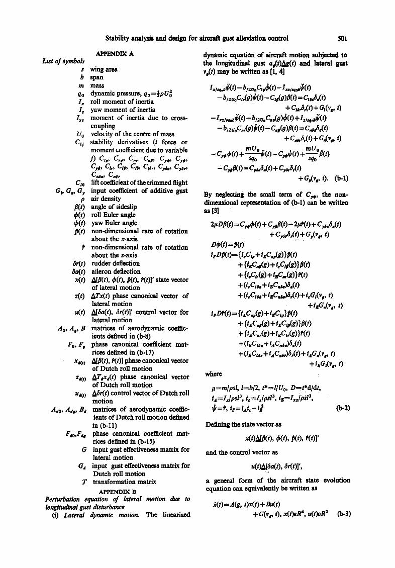
APPI~IDIX A List of symbols
s wing area b span
m mass
qo dynamic pressure, qof½pU~ Ix roll moment of inertia Is yaw moment of inertia
I~. moment of inertia due to cross- coupling
Uo velodty of the centre of mass C 0 stability derivatives (i force or
moment coefficient due to variable j ) c,., c.., c.., c.p, c.., c,,, c.p, ct,, ctp, c,,, ct,,, c,~, c.,., Css., C,~,
Cio lift coeffident of the trimmed flight G~, Gs, G r input coefficient of additive gust
p air density /~(t) angle of sideslip ~(t) roll Euler angle ~(t) yaw Euler angle ~ t ) non-dimensional rate of rotation
about the x-axis non-dimensional rate of rotation about the z-axis
6r(t) rudder deflection 6a(t) aileron deflection x(t) A[~(t), O(t), ~t), ~(t)]' state vector
of lateral motion z(O ~Tx(t) phase canonical vector of
lateral motion u(O A[6a(t), ~Sr(t)]' control vector for
lateral motion Ao, A,, B matrices of aerodynamic coeffic-
ients defined in (b-8) Fo, F, phase canonical c~efficient mat-
rices defined in (b-17) x,o) ~JP(0, ~(t)] phase canonical vector
of Dutch roll motion z~(,) AT.,x~(O phase canonical vector
of Dutch roll motion u~t o ~6r(t) control vector of Dutch roll
motion A~o. A~,. B~ matrices of aerodynamic coeffic-
ients of Dutch roll motion defined in (b-11)
F~o,F~ phase canonical coefficient mat- rices defined in (b-15)
G input gust effectiveness matrix for lateral motion
O~ input gust effectiveness matrix for Dutch roll motion
T transformation matrix APPENDIX B
Perturbation equation of lateral motion due to longitudinal gust disturbance
(i) Lateral dynamic motion. The linearized
dynamic equation of aircraft motion subjected to the longitudinal gust ~w(t)41~,(t) and lateral gust v.(0 may be written as [1, 4]
'.,..,.,4(0- b /~.o C,.$( O -1../.,oj;( O - b/2uoCi,(g)~¢(t) - Ctt(g)P(O = Cuff.O)
+G~,(O+O,%, 0 -- l.s/seodT~( t ) - b /=vo C.v(g)$( O + lsl.qO~( O
- bnuoC.,(a)¢,(O- C.p(a)P(O = ca.a.(O + C~,a,(O + G.(v,. 0
-C~$( t )+ ~ o ° ( t )- C~6(t) + ~-qUo°$(t)
- c##( O ffi c,~ao( O + c , ~ , ( O
+G~vr O. (I)-1)
By neglecting the small mrm of C,,, the non- dimensional representation of Co-l) can be v~dtten
21~DP(t)-~C,t~t) + C, pp(t)- 2/ab(t)+ c..a.(,) + c,~,a,(t) + o,%. 0
D,/,(t)=.e(O irz)p(t)= { t:c,, + iec,(e) }.e( O
+ {6,c.,(e) + t~c,~(e)}P(O + {i.c,,(e) + i~'..(e)} e(,) +q~c,k + isC.hM.(O + q.C,u + i~c.u)a.(t) + ~o,(v,. t)
+t~,(v., t) i,,~)e(t)= E,c..(%) + t~c,.}p(t)
+ {hc.,(g)+i~c,,(s)}P(O + {i~c.,(e) + t~G,(e)}e(O + (i~G~.+ Gc.s.)a.(O + (i~G~, + Gc, a,)a,(O+ Gad,. , 0
+i~6#, , t) where
p---m/psl, l=bl2, t*=llUo, D-~t*dldt, iA=lx/psl s , it=If/pal 3, iz=Iss/pM 3, ~--P, ipffiiai,-i~ (b-2)
Defining_the state vectotas
x(t)~[P(O, ~(,), P(O, e(O]'
and the control vector as
u(t)~[6a(t), 6r(t)]',
a general form of the aircraft state evolution equation can equivalently be written as
~(t)=A(g, t)x(t) + Bu(t) +c,%, O, x(t)s~, u(t)sR ~ 0,-3)
.o2
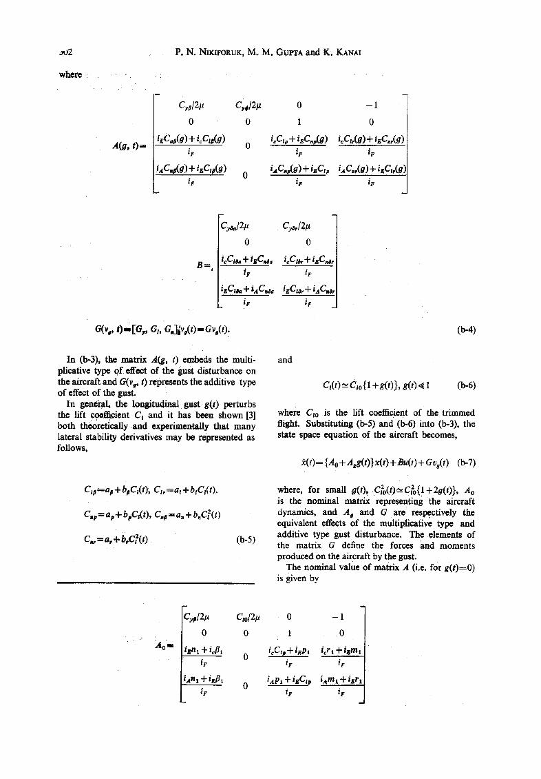
where
A(a, 0 =
P. N. NIKIFORUK, M. M. GUI~A and K. KANAI
h
C,#/2# C'¢,/21~ 0 - 1
0 0 1 0
iECna(g) + icCtp(g) 0 icC'v + iECsp(O) ieCtr(a) + igCnr(g) ie ir iF
iAC~(g) + itzC~#(g) 0 i,4C.v(g) Jl" iEClp iACnr(g ) -[- igCt,(g) iF iF iF
Bffi,
Gaa/21t C#,12#
0 0
icCtta + isC~a icCt~. + iECns, iF iF
iEC~ + i,4C~sa iECu, + iACns, iF iF
c,(,,,. O- 6,, = (b-4)
In (b-3), the matrix A(g, t) embeds the multi- plieative type of effect of the gust disturbance on the aircraft and G(vg, t) represents the additive type of effect of the gust.
In genCr~l, the lon$itudinal gust g(t) perturbs the lift coefficient Ct and it has been shown [3] both theoretically and experimentally that many lateral stability derivatives may be represented as follows,
Ctt =a# + bpC,(t), Ct, = at + blCt(t),
C.pffi ap + b pCz( t), C.a = a. + b.C,(t)
C,,,ffia,+b,C~(t) (b-5)
and
C,(t) ~ - C:o{1 +g(t)}, g(t)~ 1 (b-6)
where Cto is the lift coefficient of the trimmed fligh t. Substituting (b-5) and (b-6) into (b-3), the state space equation of the aircraft becomes,
~(t)={Ao+Agg(t)}x(t)+Bu(t)+Gvg(t) (b-7)
where, for small g(0, C~o(0"C~o{!+20(0}, Ao is the nominal matrix representing the aircraft dynamics, and Ag and G are respectively the equivalent effects of the multiplicative type and additive type gust disturbance. The elements of the matrix G define the forces and moments produced on the aircraft by the gust.
The nominal value of matrix A (i.e. for g(t)=0) is given by
Ao ' .
Cyp/21~
0
ixnl + icflt iF
[Ana + iEfll iF
Qo/2/~
0
0
0 - 1
1 . 0
icCIp+ [Eel icrl + isma iF iF
ixPl + iBClp iAmt + iBrl iF iF
Stability analysis and design for aircraft gust alleviation control
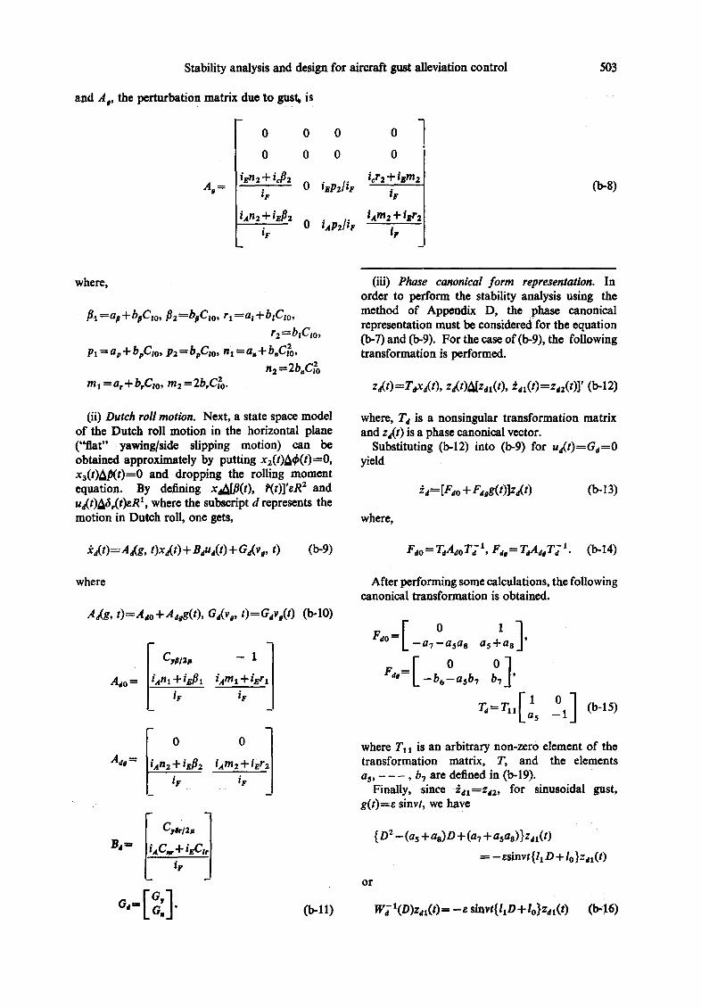
and A,, the perturbation matrix due to gust. is
0 0
0 0
ien2 + icfl2 A , = iF ....... 0
hn2 + iE/~z 0
iF
0 0
0 0
i~r2 + ibm2 isPZ/iF iF
iam2 + iBr2 hP~/iF
5O3
(b-8)
where,
fll =as + bpCto, ~2 =boC,o, rl-----at + blCw, rz =b,Cto,
Pl = ap + bpC, o, P2 = bpCto, n 1 = a. + b.C~o, n2 = 2b.C~o
m 1 = a, + b, Cio, m2 = 2b,C~o.
(ii) Dutch roll motkm. Next, a state space model of the Dutch roll motion in the horizontal plane ("fiat" yawing/side slipping motion) can be obtained approximately by putting x2(t)Adp(t)=O, xa(t)LhO(t)=O and dropping the rolling moment equation. By defining x~LS(t), P(t)]'sR z and u~(t)A6,(t)eR t, where the subscript d represents the motion in Dutch roll, one gets,
fcd(t)=Aa(g, t)xd(t) + B~ud(t)+ Ga(vo, t) (b-9)
where
Aa(g, t )=Ado+ Adeg(t), Gd(v o, t)----GdVo(t) (b-lO)
Ado
I C~,#is ~ liAnl +.ig:l
_1] Jam1.+ igrj
'F |
Ado =
Sd= ]iaC.+iEC,,[
(b-ll)
(iii) Phase canonical form representation. In order to perform the stability analysis using the method of Appendix D, the phase canonical representation must be considered for the equation (b-7) and (b-9). For the case of (b-9), the following transformation is performed.
zd(t)=Tdxd(t), zd(t)A[zjx(t), ~ax(t)=Zdz(t)]' (b-12)
where, Td is a nonsingular transformation matrix and za(t) is a phase canonical vector.
Substituting (b-12) into (b-9) for ua(t)=Gd=O yield
i~ = [F~o + Fdog(t)]z,(t) (b-13)
where,
Fao = TaA~oT~ 1, Fd~ = TaAdsT~ 1. (i>-14)
After performing some calculations, the following canonical transformation is obtained.
--aT--asas as+as ' [o o] F. .= _ b 6 _ a s b 7 b7 '
T~=TII[ls o I (bq5) - 1
where TI 1 is an arbitrary non-zero element of the transformation matrix, T, and the elements as, - - - , b7 are defined in (b-19).
Finally, since ~dl----Zd2, for sinusoidal 'gust, g(t)=8 sinvt, we have
{ D 2 - (as + as)D + (aT + asas) } Z dl(t)
= -ss invt{ l lD+lo}zdl( t )
o r
W~" l(D)zax(t) = - e sinvt{ItD+lo}z,t(t) (b-16)
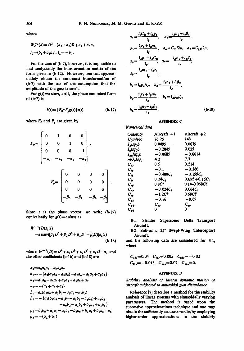
504 P .N. N w ~ g t r ~ , M. M. Gur r^ and K. KANAI
where
w ~ t(d) ffi D 2 - (a~ + as)D + a7 + asas
lo=(be +asb7), 11-~ -bT.
For the case of (b-7), however, it is impossible to find analytically the transformation matrix of the form given in (b-12). However, one can approxi- mately obtain the canonical transformation of (b-7) with the use of the assumption that the amplitude of the gust is small.
For g(t )=e sinvt, e ~ l , the phase canonical form of (b-7) is
t(O----{FotF, e(O}z(O (b.17)
t¢C~ + iep~ a I ---- j ~ '
icr I + t~ml a 3 --
iF
fxPt -I- izCi~ a 6 = iF '
iam~ + tsri a s ---- JF '
bxffiizpa/iF, b ~ - izn~+i~]2 i f '
b~ ffi i~r 2 + temz bs ffi i aPz/iF, iF
be •" /~
i~nx + iJ~
a z -- iF '
a,=C~o/21~, %=C~]2# ,
ian~ + i~Pl a 7 -- iF '
(b-lg)
where Fo and F, are Oven by
Fo m,
0 1 0
0 0 1
0 0 0
ffi
m
0
0
1
0 0 0 0
0 0 0 0
0 0 0 0
-Po -Pl
Since z is the phase vector, we write (b-17) equivalently for g ( t ) f e sinvt as
W- l(D)zl(t) =e sinvtLB~D 3 -t-~2D 2 +~ID ~ + ~o(t)]Zx(t)
(b-IS)
where W - I ( D ) = D 4 +%D3 +%D2 +o~xD+uo and the other coefficients (b-16) and 0>-18) are
O~ o ~ a2a4a s -- a3a, a 7
oq ~- -- {as(ala e -- a3a6) + a2a4-- aaae + ala 7 }
% ~a lae -- a3a6 + alas + asae + a7
• 3----- --(ax +as +as) /$0 =a4(b2ae + a2b7 - a3ae - aTb3)
/Jr ~- - {as(bias + alb7 - a3bs - b3a6) + a4b2
-a6b2 -a2b5 + bla7 + axb~ }
~2~-btbe + alaT-a3bs -b3a6 + b1% + bTas + b6
P3=-C01 +bT)
~ C Numerical data
Quantity Aircraft ~ 1 Aircraft ~ 2 Uom/sec 76.25 148 lx/sqob 0.0495 0.0079 l,/sqob -0.2845 0.025 l~,lsqob - 0.0685 -0.0014 mUo[sqo 4.2 7.7 Cto 0. 5 0. 514 C,p -0 .1 -0 .360 Ct# -0.488C~ -0.199C~ Ct, 0.24Ci 0.075 +0.16C~ C o 0.8C 2 0"14-0"058C~ C.e -0.024Cz 0.064C, c,, - t .2c , 0.6sc C,# -0 .16 -0 .69
C,o C,o C,, o o
@ 1 : Slender Supersonic Delta Tramport Aircraft,
#2 : Sub-sonic 35 ° Swept-Wing (Interceptor) Aircraft,
and the following data are considered for # 1, where
Cys,=O.04 C~o,=0.005 C,6,~--0.02
Cz6a-----0.015 C . . = 0 . 0 2 C,,o=O.
APPENDIX D
Stability analysis of lateral dynamic motion of aircraft subjected to stnusoidai gust disturbance
Reference [7] describes a method for the stabifity analysis of finear systems with sinusoidally varying parameters. The method is based upon the successive approximations technique and one may obtain the sufficiently accurate results by employing higher-order approximations in the stability
Stability analysis and design for airoraft gust alleviation control 505
analysis. I f the system possesses sufficient low- pass characteristics, however, the first-order approximations will yield sufficiently accurate results. This reference considers many examples having different assignment conditions, however, in this appendix we will illustrate the method by a particular example of aircraft in its lateral dynamic motion. The motion in the phase-canonical form is described in (b-18), and since the air~,raft possesses sufficient low pass characteristics, only first-order approximation will be employed.
The dynamic equation of lateral motion of the aircraft with zero input and subjected to gust disturbance on its parameters is described in (b-18) and is given by
= e sinvt[j3~D s + [3~D z +#1 D "l" j~dZl(t) (d-l)
where
sino t = 8 ,l w(do )l(o )qin( on + 4,
+ i ~ ) sinvt (d-4)
where the product sin(o~t+4,+in/2)sinvt on the right hand side of (d-4) produces two harmonics of frequencies (~4-v). Assuming that the aircraft possesses sufficient low-pass characteristics, one may safely assume that ¢o=v]2 in (d-4). Thus (d-4) becomes
+(,;) (+)'oo,(+-, - - j .
Equating the amplitudes on both sides of this equat ion, one gets
W(D)-t= D4 +o~sDS +o~2D2 +oq D t +%
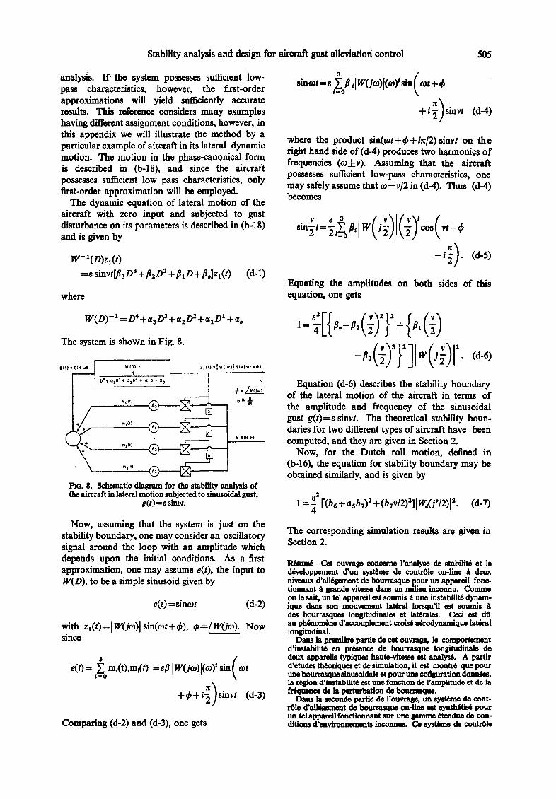
The system is shown in Fig. 8.
elt) ~ t
t 04+ 03 o3÷ azOz + aid + ~o 1
ra°(t)
1 m3D )
1~o. 8. Schematic diagram for the stability analysis of the aircraft in lateral motion subjected to sinusoidal gust,
g(t)fe sinvt.
W(D) • Zl (f) • [ W (]oJ)l SIN (Wt +@)
• d
~ SiN VI 4
Now, assuming that the system is just on the stability boundary, one may consider an oscillatory signal around the loop with an amplitude which depends upon the initial conditions. As a first approximation, one may assume e(t), the input to W(D), to be a simple sinusoid given by
e(t)=sincot (d-2)
with zl(O=lwfjco)[ sin(o~t+4,), 4,=/W(jo,). Now since
3 ( e( t ) - ~ m~t),m~t) --eft Iw0o )l(o )' sm o~t
iffiO
+++,-:)s+, Comparing (d-2) and (d-3), one gets
(d-6) D
Equation (d-6) describes the stability boundary of the lateral motion of the aircraft in terms of the amplitude and frequency of the sinusoidal gust g(t)=e sinvt. The theoretical stability boun- daries for two different types of aircraft have been computed, and they are given in Section 2.
Now, for the Dutch roll motion, defined in 0>-16), the equation for stability boundary may be obtained similarly, and is given by
8 2
1 = 71 [(b6+asbT)Z+(bTv/2)z][Wj(j'/2)12" (d-7)
The corresponding simulation results are given in Section 2.
RAsuw~ Cot ouvrage concerne l'analyse de stabilit6 et ]e dtve, loppement d'un systhne de contr01e on-line A deux nlveaux d'alltgement de bourrasque pour un appareil lone- t i o n n a n t ~ ~ ! 3 d ~ vJte~kqe c ~ n n r ~ e t l i n o o n n u . CO11~11e
on le sait, un tel appareil est soumis A une imtabilit6 dynam- ique dans son mouvemcat la th~ Iorsqu'il est sounds A des bourrasqum longitudinales et lat~rales. Cezi est dQ au ph~mom~ne d'accouplement crois6 atrodynamique la~ral longitudinal.
Darts la premiere partie de cot ouvrag~ le comportement d'instabilit6 e~ pr~enc~ de bourrasque longitudinnle de deux appareils typiques haute-vitese ¢st Analys6. A partir d'ttudes thtoriques et de simulation, il est montr6 que pour une bourrasque sinusoldale et pour une cofiguration donntes, la r~ ion d'imtabflit6 est tree fonction de l'amplitude et de la fr~uence de la perturbation de bourrasque.
Dam la seconde partie de l'ouvrage, un syst~me de cont- rtl© d'alltgement de bourrasque on-line est synflK'ti~ pour un tel appare/l fonctionnant sur une gamme 6tendue de con- ditions d'cavironnemeats inconnm. Ce systhne de contr01e
506 P . N . NIKIZORUKI M. M. GUPTA a n d K. KASA~
fait emploi d'une structure de contr~le b demc niveaux. Le contr61eur toutefois ne demande pas une connaissance explicite des param~tres de l'appareil ou de l'environnement. Des r~sultats typiques de simulation sont pr~sent~s qui v~rifient les pr6visions thb3riques.
Zusammeafammg--Die Arbeit betrifft die Stabili~tsanalyse und die Entwicklung eines on-line-Zweiebenen-Regelungs- systems zur Milderung des Einflusses yon B6en auf ein Flugzeug hoher Geschwindigkeit, das in unbekannter Umgebung operiert. Es ist wohlbekannt, ~ ein solches Flugzeug in seiner seitlichen Bewegung dynamische Instabi- lit~t erfLhrt, wean es longitudinalen und lateralen BSen unterwoffen ist. Das folgt aus dem Phitnomen lateral- longitudinaler aerodynamischer Kreuzkopplung.
Im ersten Teil dieser Arbeit wird das instabile Verhalten yon zwei Hochgeschwindigkeitsflugzeusen beiVorhandensein einer longitudinalen B5 analysiert. Durch theoretische und Simulationsstudien wird gezeigt, dab fiir eine sinusfOrmige B6 und eine gegebene Konfigumtion der Instabilitatsbereich sowohl eine Funktion der Amplitude als auch der Frequenz der B6st6rung ist.
Im zweiten Tell der Arbeit wird ein on-line Regelungs- system zur Milderung des Einflusses von B ~ n f'tir ein solches Flugzeug Synthetisiert, das in einem weiten Bereich unbek- annter Umgebungsbedingungen operiert. Der Regler erfordert indessen keine explizite Kenntnis der Flugzeug- parameter oder der Umgebung. Typische Resultate der
Simulation werden angeflLhrt, die die theoretischen Vorher- sagen verifizieren.
PesmMe----CTaTbg nocBallIeHa aHaHH3y ycToam~oc'ra K co3~mmo £(wfxypoBnenog cw~'reM~ ~ e a m a B pea~noM MacmTa6e ~aa BIalOg:)KOCKOpOffrHOFO caMo~eTa, pa6oTalOni- ere B neH3secTmax ycaoBsax x o6aer,m~omaa sana~me BHe3arlHldX Harpy3og. I ~ xoponlo H3I~'THO, HO,ZlO6Hldg caMoHeT HO~BepXeH ~ ~ g O l i HeyCTOli~¢rH npH HOHepeqHldX ~LBHXe~ 1/DH HaJIMq_~/H npo~oYn~HMX H nonepeqH~JX noptdBOB. ~ r o o~-'To.qTeJna~rBo CBH3aHO C ~neHHeM npo~on],HO-nonepe~moi~ a3po~aMH~ecgog CBR3KH.
B HepBon ~aCTH CTaTha aHan~13~pyercs HeyCTOl~m~Tb IIpn npojloJn~IH,1x HOpldBaX. ~JTO ,/leJlat~rcg ~ ~ByX THHOB- tdx B~COgOCgOpOCTH]~ CaMOJIeTOB. TeOpeTHqecKHC H MO~eJIbI-I~le HCCJIe~OBaHHq I]OKa3aJIH, ~ITO ~ CI~fCOH- Ran~m~x Harpy3og H ~ ~aitaon gOHC~Hrypatlum o ~ r b H e y c ~ o ~ n ~ e - r c s ~pymm~el~, gag aMn.rlHTy~H, Tag X ~mCTOTS~ ~eTpoB~ax ~o~My~enm~.
Bo BTOpOR qaCTH craT~n CHHTe311pye'rca cHcre~a ynpas- neHHg ~ ig K O M H e H ~ Harpy~og ~ m nO~lOOHOrO caMon- eTa, pa6oTa~omero B mapogoM HHana3oHe HeH3BC~THldX BHen/HHX ycnoBm~. ~ cH~'eMa ynpaBHeHILq HMe~T ~ByxypoBHeBy~O cTpygTypy. O~HagO pery~rrop He Tpe6yeT o6~eMmomero 3nam~ r/apaM~TpOB caMoHeTa a BHeIHHIIX yCnOBH~[. ]-Ipc~cTa~rlCH~ THHOBHe pe3y~TaTM Mo~Ie- nHpOBaH~S, upoBepa~o~H~e TeOpeTnqecg~e npe~cga3aH~.


![RJ1 RJ 2 RJ 5L RJ 5R RJ 19 RJ 18 RJ 6 RJ 7 RJ 11 RJ 5R RJ ...Parts]--Jr.pdf · RJ 3 RJ 8 RJ 11 RJ 6 RJ 5R RJ 4 RJ 26 RJ 27 RJ 28 RJ 29 RJ 5L SPECIAL PAWL For clockwise rotation, a](https://img.pdfslide.us/doc/110x75/5f7bfd0580b79229701f388e/rj1-rj-2-rj-5l-rj-5r-rj-19-rj-18-rj-6-rj-7-rj-11-rj-5r-rj-parts-jrpdf-rj.jpg)