Embed Size (px)
Citation preview

Sta-Kon ® Wire Termination & Insulation
In this section...
Sta-Kon® Wire Termination & Insulation
Overview ........................................................................... G-2–G-3
Ring Terminals ................................................................ G-4–G-13
Flag Terminals .........................................................................G-14
Fork Terminals ............................................................... G-15–G-19
Pin Terminals ...........................................................................G-19
Splice Connectors .......................................................... G-20–G-21
Wire Joints .................................................................... G-22–G-23
Heat-Shrinkable Terminals, Splices, Disconnects ...................................................... G-24–G-25
Disconnects and Male Tabs ........................................... G-26–G-29
Luminaire Disconnects .................................................. G-30–G-31
Ferrules ......................................................................... G-32–G-35
Wire Termination Tools and Installation Kits ................... G-36–G-45
Wire Termination Technical Information ......................... G-46–G-57
Shrink-Kon® Heat-Shrinkable Tubing ............................. G-58–G-70
Shrink-Kon® Splice Insulators and Insulating Covers .................................................... G-71–G-74
Shrink-Kon® Installation Tools ........................................ G-75–G-77
Shield-Kon® Shield Termination System......................... G-78–G-91
Dragon-Tooth® Magnet Wire Termination System ..................................................... G-92–G-104
www.tnb.comUnited States
Tel: 901.252.8000 800.816.7809Fax: 901.252.1354
Technical Services
Tel: 888.862.3289G-2
Overview
Wir
e Te
rmin
atio
n —
Sta
-Kon
® W
ire T
erm
inat
ion
& In
sula
tion
Selectively annealed long barrel
Longer barrel design Color-coded insulators Brazed or overlapping seams
Anti-rotational tongue Hardened tongue Complete wire and stud size identification
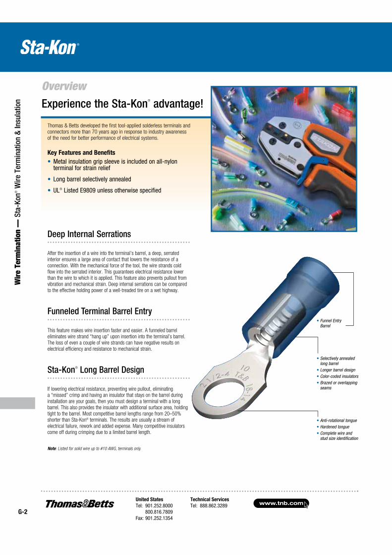
Thomas & Betts developed the first tool-applied solderless terminals and connectors more than 70 years ago in response to industry awareness of the need for better performance of electrical systems.
Key Features and Benefits
UL®
Experience the Sta-Kon® advantage!
Funnel Entry Barrel
Deep Internal Serrations
After the insertion of a wire into the terminal’s barrel, a deep, serrated interior ensures a large area of contact that lowers the resistance of a connection. With the mechanical force of the tool, the wire strands cold flow into the serrated interior. This guarantees electrical resistance lower than the wire to which it is applied. This feature also prevents pullout from vibration and mechanical strain. Deep internal serrations can be compared to the effective holding power of a well-treaded tire on a wet highway.
Funneled Terminal Barrel Entry
This feature makes wire insertion faster and easier. A funneled barrel eliminates wire strand “hang up” upon insertion into the terminal’s barrel. The loss of even a couple of wire strands can have negative results on electrical efficiency and resistance to mechanical strain.
Sta-Kon® Long Barrel Design
If lowering electrical resistance, preventing wire pullout, eliminating a “missed” crimp and having an insulator that stays on the barrel during installation are your goals, then you must design a terminal with a long barrel. This also provides the insulator with additional surface area, holding tight to the barrel. Most competitive barrel lengths range from 20–50% shorter than Sta-Kon® terminals. The results are usually a stream of electrical failure, rework and added expense. Many competitive insulators come off during crimping due to a limited barrel length.
Note: Listed for solid wire up to #10 AWG, terminals only.
United States
Tel: 901.252.8000 800.816.7809Fax: 901.252.1354
Technical Services
Tel: 888.862.3289www.tnb.com
G-3
Wire Term
ination — Sta-Kon
® Wire Term
ination & Insulation
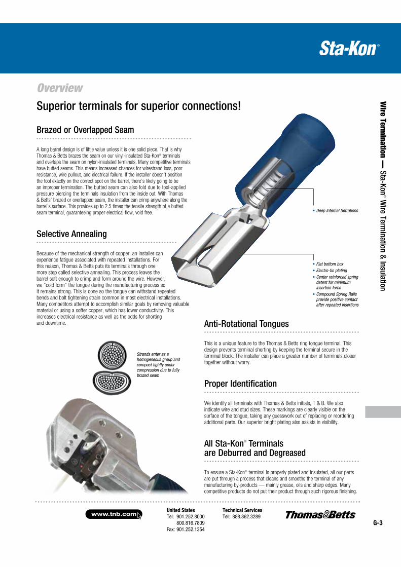
Overview Superior terminals for superior connections!
Deep Internal Serrations
Flat bottom box Electro-tin plating Center reinforced spring detent for minimum insertion force
Compound Spring Rails provide positive contact after repeated insertions
Strands enter as a homogeneous group and compact tightly under compression due to fully brazed seam
Brazed or Overlapped Seam
A long barrel design is of little value unless it is one solid piece. That is why Thomas & Betts brazes the seam on our vinyl-insulated Sta-Kon® terminals and overlaps the seam on nylon-insulated terminals. Many competitive terminals have butted seams. This means increased chances for wirestrand loss, poor resistance, wire pullout, and electrical failure. If the installer doesn’t position the tool exactly on the correct spot on the barrel, there’s likely going to be an improper termination. The butted seam can also fold due to tool-applied pressure piercing the terminals insulation from the inside out. With Thomas & Betts’ brazed or overlapped seam, the installer can crimp anywhere along the barrel’s surface. This provides up to 2.5 times the tensile strength of a butted seam terminal, guaranteeing proper electrical flow, void free.
Selective Annealing
Because of the mechanical strength of copper, an installer can experience fatigue associated with repeated installations. For this reason, Thomas & Betts puts its terminals through one more step called selective annealing. This process leaves the barrel soft enough to crimp and form around the wire. However, we “cold form” the tongue during the manufacturing process so it remains strong. This is done so the tongue can withstand repeated bends and bolt tightening strain common in most electrical installations. Many competitors attempt to accomplish similar goals by removing valuable material or using a softer copper, which has lower conductivity. This increases electrical resistance as well as the odds for shorting and downtime. Anti-Rotational Tongues
This is a unique feature to the Thomas & Betts ring tongue terminal. This design prevents terminal shorting by keeping the terminal secure in the terminal block. The installer can place a greater number of terminals closer together without worry.
Proper Identification
We identify all terminals with Thomas & Betts initials, T & B. We also indicate wire and stud sizes. These markings are clearly visible on the surface of the tongue, taking any guesswork out of replacing or reordering additional parts. Our superior bright plating also assists in visibility.
All Sta-Kon® Terminals are Deburred and Degreased
To ensure a Sta-Kon® terminal is properly plated and insulated, all our parts are put through a process that cleans and smooths the terminal of any manufacturing by-products — mainly grease, oils and sharp edges. Many competitive products do not put their product through such rigorous finishing.
www.tnb.comUnited States
Tel: 901.252.8000 800.816.7809Fax: 901.252.1354
Technical Services
Tel: 888.862.3289G-4
Ring Terminals
Wir
e Te
rmin
atio
n —
Sta
-Kon
® W
ire T
erm
inat
ion
& In
sula
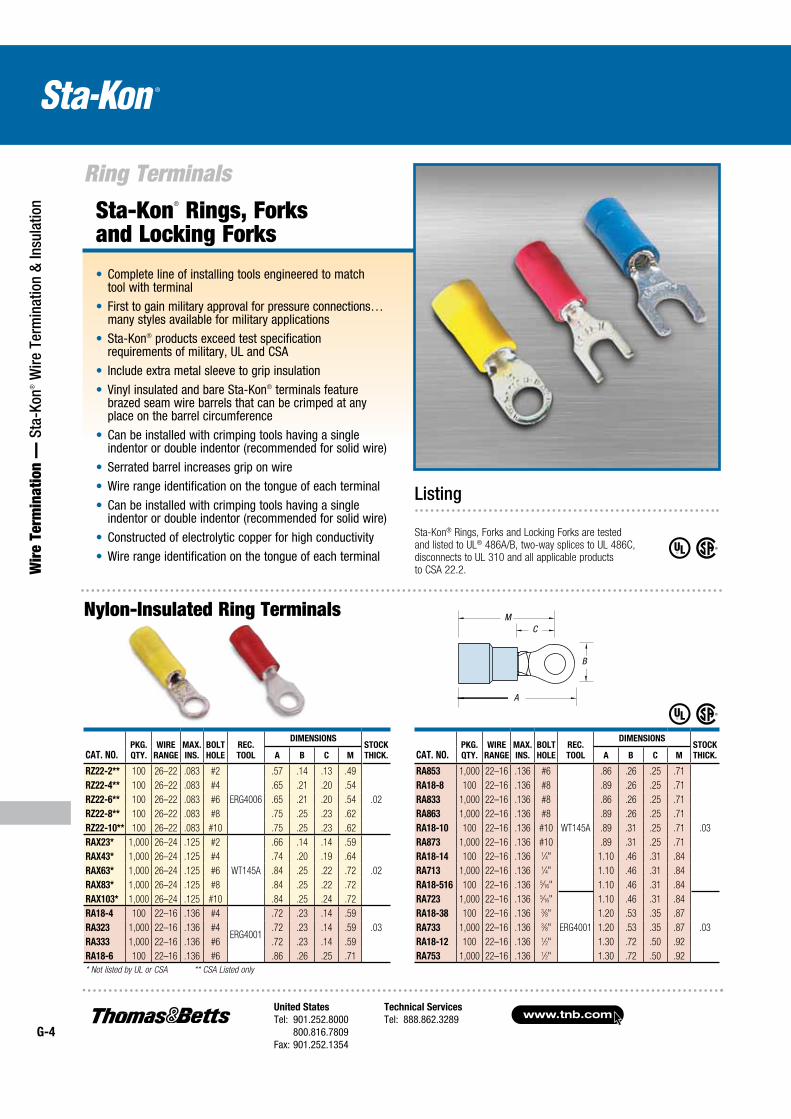
tion Sta-Kon® Rings, Forks
and Locking Forks
Complete line of installing tools engineered to match tool with terminal
First to gain military approval for pressure connections… many styles available for military applications
Sta-Kon® products exceed test specification requirements of military, UL and CSA
Include extra metal sleeve to grip insulation
Vinyl insulated and bare Sta-Kon® terminals feature brazed seam wire barrels that can be crimped at any place on the barrel circumference
Can be installed with crimping tools having a single indentor or double indentor (recommended for solid wire)
Serrated barrel increases grip on wire
Wire range identification on the tongue of each terminal
Can be installed with crimping tools having a single indentor or double indentor (recommended for solid wire)
Constructed of electrolytic copper for high conductivity
Wire range identification on the tongue of each terminal
Listing
Sta-Kon® Rings, Forks and Locking Forks are tested and listed to UL® 486A/B, two-way splices to UL 486C, disconnects to UL 310 and all appli cable products to CSA 22.2.
Nylon-Insulated Ring Terminals
CAT. NO.PKG.
QTY.
WIRE
RANGE
MAX.
INS.
BOLT
HOLE
REC.
TOOL
DIMENSIONSSTOCK
THICK.A B C M
RZ22-2** 100 26–22 .083 #2
ERG4006
.57 .14 .13 .49
RZ22-4** 100 26–22 .083 #4 .65 .21 .20 .54
RZ22-6** 100 26–22 .083 #6 .65 .21 .20 .54 .02
RZ22-8** 100 26–22 .083 #8 .75 .25 .23 .62
RZ22-10** 100 26–22 .083 #10 .75 .25 .23 .62
RAX23* 1,000 26–24 .125 #2
WT145A
.66 .14 .14 .59
RAX43* 1,000 26–24 .125 #4 .74 .20 .19 .64
RAX63* 1,000 26–24 .125 #6 .84 .25 .22 .72 .02
RAX83* 1,000 26–24 .125 #8 .84 .25 .22 .72
RAX103* 1,000 26–24 .125 #10 .84 .25 .24 .72
RA18-4 100 22–16 .136 #4
ERG4001
.72 .23 .14 .59
RA323 1,000 22–16 .136 #4 .72 .23 .14 .59 .03
RA333 1,000 22–16 .136 #6 .72 .23 .14 .59
RA18-6 100 22–16 .136 #6 .86 .26 .25 .71
* Not listed by UL or CSA ** CSA Listed only
CAT. NO.PKG.
QTY.
WIRE
RANGE
MAX.
INS.
BOLT
HOLE
REC.
TOOL
DIMENSIONSSTOCK
THICK.A B C M
RA853 1,000 22–16 .136 #6 .86 .26 .25 .71
RA18-8 100 22–16 .136 #8 .89 .26 .25 .71
RA833 1,000 22–16 .136 #8 .86 .26 .25 .71
RA863 1,000 22–16 .136 #8 .89 .26 .25 .71
RA18-10 100 22–16 .136 #10 WT145A .89 .31 .25 .71 .03
RA873 1,000 22–16 .136 #10 .89 .31 .25 .71
RA18-14 100 22–16 .136 1⁄4" 1.10 .46 .31 .84
RA713 1,000 22–16 .136 1⁄4" 1.10 .46 .31 .84
RA18-516 100 22–16 .136 5⁄16" 1.10 .46 .31 .84
RA723 1,000 22–16 .136 5⁄16" 1.10 .46 .31 .84
RA18-38 100 22–16 .136 3⁄8" 1.20 .53 .35 .87
RA733 1,000 22–16 .136 3⁄8" ERG4001 1.20 .53 .35 .87 .03
RA18-12 100 22–16 .136 1⁄2" 1.30 .72 .50 .92
RA753 1,000 22–16 .136 1⁄2" 1.30 .72 .50 .92
M
B
A
CM
United States
Tel: 901.252.8000 800.816.7809Fax: 901.252.1354
Technical Services
Tel: 888.862.3289www.tnb.com
G-5
Ring Terminals
Wire Term
ination — Sta-Kon
® Wire Term
ination & Insulation
Nylon-Insulated Ring Terminals (continued)
Nylon-Insulated Ring Terminals — Expanded Entry
CAT. NO.PKG.
QTY.
WIRE
RANGE
MAX.
INS.
BOLT
HOLE
REC.
TOOL
DIMENSIONSSTOCK
THICK.A B C M
RB14-4 100 18–14 .162 #4 .72 .26 .14 .59
RB1323 1,000 18–14 .162 #4 .72 .26 .14 .59
RB14-6 100 18–14 .162 #6 .89 .31 .25 .71
RB853 1,000 18–14 .162 #6 .89 .31 .25 .71
RB1333 1,000 18–14 .162 #6 .74 .26 .14 .59
RB14-8 100 18–14 .162 #8 .89 .31 .25 .71
RB863 1,000 18–14 .162 #8 .89 .31 .25 .71
RB14-10 100 18–14 .162 #10 .89 .31 .25 .71
RB873 1,000 18–14 .162 #10 ERG4001 .89 .31 .25 .71 .03
RB14-14 100 18–14 .162 1⁄4" 1.08 .47 .31 .81
RB713 1,000 18–14 .162 1⁄4" 1.08 .47 .31 .81
RB14-516 100 18–14 .162 5⁄16" 1.08 .47 .31 .84
RB723 1,000 18–14 .162 5⁄16" 1.08 .47 .31 .84
RB14-38 100 18–14 .162 3⁄8" 1.17 .53 .35 .87
RB733 1,000 18–14 .162 3⁄8" 1.17 .53 .35 .87
RB14-12 100 18–14 .162 1⁄2" 1.25 .72 .50 .90
RB753 1,000 18–14 .162 1⁄2" 1.25 .72 .50 .90
CAT. NO.PKG.
QTY.
WIRE
RANGE
MAX.
INS.
BOLT
HOLE
REC.
TOOL
DIMENSIONSSTOCK
THICK.A B C M
RB14-4X 100 18–14 .190 #4 .80 .26 .14 .67
RB14-6X 100 18–14 .190 #6 .95 .31 .25 .79
RB854 1,000 18–14 .190 #6 .95 .31 .25 .79
RB14-8X 100 18–14 .190 #8 .95 .31 .25 .79
RB864 1,000 18–14 .190 #8 .95 .31 .25 .79
RB14-10X 100 18–14 .190 #10ER4001
.95 .31 .25 .79 .03
RB874 1,000 18–14 .190 #10 .95 .31 .25 .79
RB14-14X 100 18–14 .190 1⁄4" 1.16 .47 .31 .92
RB714 1,000 18–14 .190 1⁄4" 1.16 .47 .31 .92
RB14-516X 100 18–14 .190 5⁄16" 1.16 .47 .31 .92
RB724 1,000 18–14 .190 5⁄16" 1.16 .47 .31 .92
RB14-38X 100 18–14 .190 3⁄8" 1.25 .53 .42 .95
RB734 1,000 18–14 .190 3⁄8" 1.25 .53 .42 .95
UL Listed E9809
CAT. NO.PKG.
QTY.
WIRE
RANGE
MAX.
INS.
BOLT
HOLE
REC.
TOOL
DIMENSIONSSTOCK
THICK.A B C M
RC10-6 50 12–10 .210 #6 1.00 .37 .27 .81
RC333 500 12–10 .210 #6 1.00 .37 .27 .81
RC10-8 50 12–10 .210 #8 1.00 .37 .27 .81
RC863 500 12–10 .210 #8 1.00 .37 .27 .81
RC10-10 50 12–10 .210 #10 1.00 .37 .27 .81
RC363 500 12–10 .210 #10 1.00 .37 .27 .81
RC10-14 50 12–10 .210 1⁄4" ERG4001 1.12 .53 .32 .86 .04
RC713 500 12–10 .210 1⁄4" 1.12 .53 .32 .86
RC10-516 50 12–10 .210 5⁄16" 1.21 .53 .31 .94
RC703 500 12–10 .210 5⁄16" 1.21 .53 .31 .94
RC10-38 50 12–10 .210 3⁄8" 1.27 .59 .35 .98
RC733 500 12–10 .210 3⁄8" 1.27 .59 .35 .98
RC10-12 50 12–10 .210 1⁄2" 1.37 .72 .52 1.02
RC753 500 12–10 .210 1⁄2" 1.37 .72 .52 1.02
CAT. NO.PKG.
QTY.
WIRE
RANGE
MAX.
INS.
BOLT
HOLE
REC.
TOOL
DIMENSIONSSTOCK
THICK.A B C M
RC10-6X 50 12–10 .250 #6 1.10 .37 .27 .91
RC334 500 12–10 .250 #6 1.10 .37 .27 .91
RC10-8X 50 12–10 .250 #8 1.10 .37 .27 .91
RC864 500 12–10 .250 #8 1.10 .37 .27 .91
RC10-10X 50 12–10 .250 #10 1.10 .37 .27 .91
RC364 500 12–10 .250 #10 1.10 .37 .27 .91
RC10-14X 50 12–10 .250 1⁄4" ERG4001 1.22 .53 .32 .96 .04
RC714 500 12–10 .250 1⁄4" 1.22 .53 .32 .96
RC10-516X 50 12–10 .250 5⁄16" 1.32 .53 .31 1.05
RC704 500 12–10 .250 5⁄16" 1.32 .53 .31 1.05
RC10-38X 50 12–10 .250 3⁄8" 1.38 .59 .48 1.09
RC734 500 12–10 .250 3⁄8" 1.38 .59 .48 1.09
RC10-12X 50 12–10 .250 1⁄2" 1.48 .72 .52 1.13
M
B
A
CM
M
B
A
CM
www.tnb.comUnited States
Tel: 901.252.8000 800.816.7809Fax: 901.252.1354
Technical Services
Tel: 888.862.3289G-6
Ring Terminals
Wir
e Te
rmin
atio
n —
Sta
-Kon
® W
ire T
erm
inat
ion
& In
sula
tion
*Brazed Seam
AN=Aircraft Wire
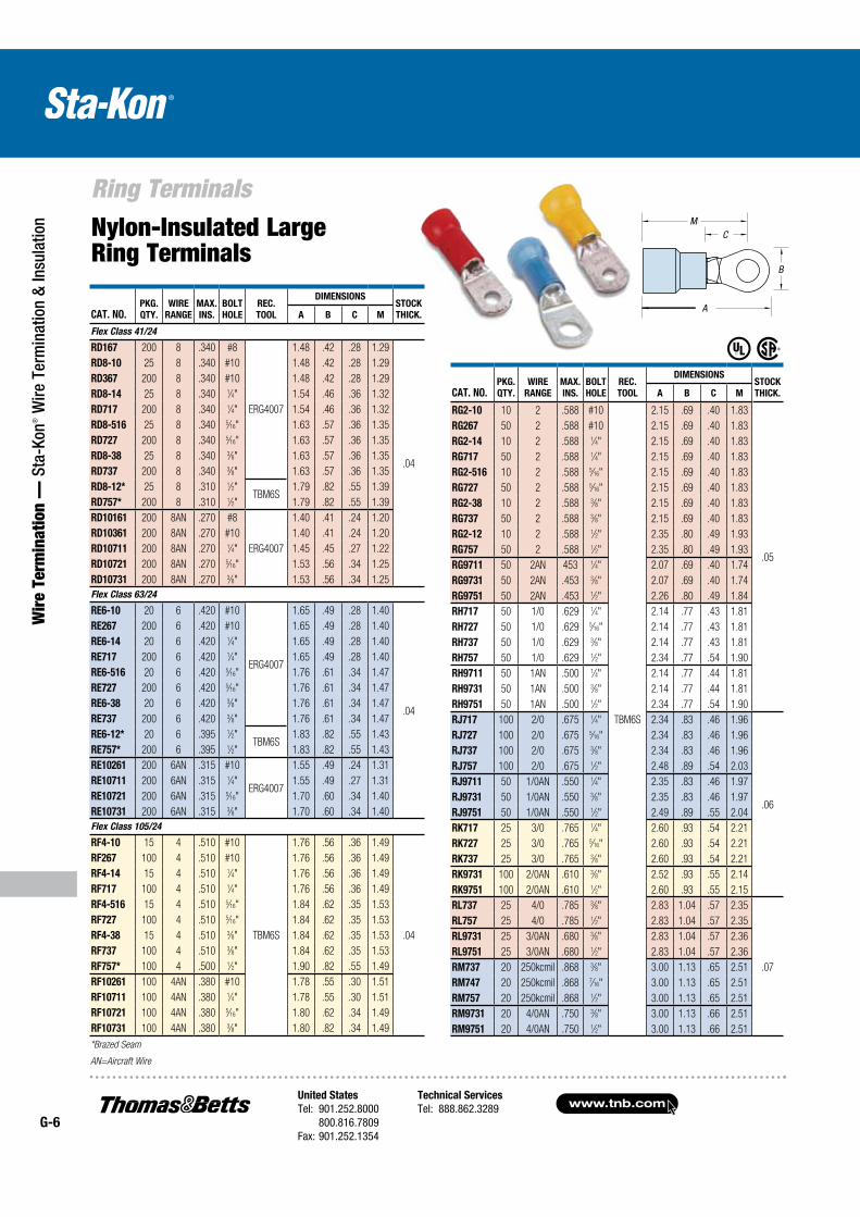
Nylon-Insulated Large Ring Terminals
CAT. NO.PKG.
QTY.
WIRE
RANGE
MAX.
INS.
BOLT
HOLE
REC.
TOOL
DIMENSIONSSTOCK
THICK.A B C M
Flex Class 41/24
RD167 200 8 .340 #8
ERG4007
1.48 .42 .28 1.29
.04
RD8-10 25 8 .340 #10 1.48 .42 .28 1.29
RD367 200 8 .340 #10 1.48 .42 .28 1.29
RD8-14 25 8 .340 1⁄4" 1.54 .46 .36 1.32
RD717 200 8 .340 1⁄4" 1.54 .46 .36 1.32
RD8-516 25 8 .340 5⁄16" 1.63 .57 .36 1.35
RD727 200 8 .340 5⁄16" 1.63 .57 .36 1.35
RD8-38 25 8 .340 3⁄8" 1.63 .57 .36 1.35
RD737 200 8 .340 3⁄8" 1.63 .57 .36 1.35
RD8-12* 25 8 .310 1⁄2"TBM6S
1.79 .82 .55 1.39
RD757* 200 8 .310 1⁄2" 1.79 .82 .55 1.39
RD10161 200 8AN .270 #8
ERG4007
1.40 .41 .24 1.20
RD10361 200 8AN .270 #10 1.40 .41 .24 1.20
RD10711 200 8AN .270 1⁄4" 1.45 .45 .27 1.22
RD10721 200 8AN .270 5⁄16" 1.53 .56 .34 1.25
RD10731 200 8AN .270 3⁄8" 1.53 .56 .34 1.25
Flex Class 63/24
RE6-10 20 6 .420 #10
ERG4007
1.65 .49 .28 1.40
.04
RE267 200 6 .420 #10 1.65 .49 .28 1.40
RE6-14 20 6 .420 1⁄4" 1.65 .49 .28 1.40
RE717 200 6 .420 1⁄4" 1.65 .49 .28 1.40
RE6-516 20 6 .420 5⁄16" 1.76 .61 .34 1.47
RE727 200 6 .420 5⁄16" 1.76 .61 .34 1.47
RE6-38 20 6 .420 3⁄8" 1.76 .61 .34 1.47
RE737 200 6 .420 3⁄8" 1.76 .61 .34 1.47
RE6-12* 20 6 .395 1⁄2"TBM6S
1.83 .82 .55 1.43
RE757* 200 6 .395 1⁄2" 1.83 .82 .55 1.43
RE10261 200 6AN .315 #10
ERG4007
1.55 .49 .24 1.31
RE10711 200 6AN .315 1⁄4" 1.55 .49 .27 1.31
RE10721 200 6AN .315 5⁄16" 1.70 .60 .34 1.40
RE10731 200 6AN .315 3⁄8" 1.70 .60 .34 1.40
Flex Class 105/24
RF4-10 15 4 .510 #10
TBM6S
1.76 .56 .36 1.49
.04
RF267 100 4 .510 #10 1.76 .56 .36 1.49
RF4-14 15 4 .510 1⁄4" 1.76 .56 .36 1.49
RF717 100 4 .510 1⁄4" 1.76 .56 .36 1.49
RF4-516 15 4 .510 5⁄16" 1.84 .62 .35 1.53
RF727 100 4 .510 5⁄16" 1.84 .62 .35 1.53
RF4-38 15 4 .510 3⁄8" 1.84 .62 .35 1.53
RF737 100 4 .510 3⁄8" 1.84 .62 .35 1.53
RF757* 100 4 .500 1⁄2" 1.90 .82 .55 1.49
RF10261 100 4AN .380 #10 1.78 .55 .30 1.51
RF10711 100 4AN .380 1⁄4" 1.78 .55 .30 1.51
RF10721 100 4AN .380 5⁄16" 1.80 .62 .34 1.49
RF10731 100 4AN .380 3⁄8" 1.80 .82 .34 1.49
CAT. NO.PKG.
QTY.
WIRE
RANGE
MAX.
INS.
BOLT
HOLE
REC.
TOOL
DIMENSIONSSTOCK
THICK.A B C M
RG2-10 10 2 .588 #10
TBM6S
2.15 .69 .40 1.83
.05
RG267 50 2 .588 #10 2.15 .69 .40 1.83
RG2-14 10 2 .588 1⁄4" 2.15 .69 .40 1.83
RG717 50 2 .588 1⁄4" 2.15 .69 .40 1.83
RG2-516 10 2 .588 5⁄16" 2.15 .69 .40 1.83
RG727 50 2 .588 5⁄16" 2.15 .69 .40 1.83
RG2-38 10 2 .588 3⁄8" 2.15 .69 .40 1.83
RG737 50 2 .588 3⁄8" 2.15 .69 .40 1.83
RG2-12 10 2 .588 1⁄2" 2.35 .80 .49 1.93
RG757 50 2 .588 1⁄2" 2.35 .80 .49 1.93
RG9711 50 2AN 453 1⁄4" 2.07 .69 .40 1.74
RG9731 50 2AN .453 3⁄8" 2.07 .69 .40 1.74
RG9751 50 2AN .453 1⁄2" 2.26 .80 .49 1.84
RH717 50 1/0 .629 1⁄4" 2.14 .77 .43 1.81
RH727 50 1/0 .629 5⁄16" 2.14 .77 .43 1.81
RH737 50 1/0 .629 3⁄8" 2.14 .77 .43 1.81
RH757 50 1/0 .629 1⁄2" 2.34 .77 .54 1.90
RH9711 50 1AN .500 1⁄4" 2.14 .77 .44 1.81
RH9731 50 1AN .500 3⁄8" 2.14 .77 .44 1.81
RH9751 50 1AN .500 1⁄2" 2.34 .77 .54 1.90
RJ717 100 2/0 .675 1⁄4" 2.34 .83 .46 1.96
.06
RJ727 100 2/0 .675 5⁄16" 2.34 .83 .46 1.96
RJ737 100 2/0 .675 3⁄8" 2.34 .83 .46 1.96
RJ757 100 2/0 .675 1⁄2" 2.48 .89 .54 2.03
RJ9711 50 1/0AN .550 1⁄4" 2.35 .83 .46 1.97
RJ9731 50 1/0AN .550 3⁄8" 2.35 .83 .46 1.97
RJ9751 50 1/0AN .550 1⁄2" 2.49 .89 .55 2.04
RK717 25 3/0 .765 1⁄4" 2.60 .93 .54 2.21
RK727 25 3/0 .765 5⁄16" 2.60 .93 .54 2.21
RK737 25 3/0 .765 3⁄8" 2.60 .93 .54 2.21
RK9731 100 2/0AN .610 3⁄8" 2.52 .93 .55 2.14
RK9751 100 2/0AN .610 1⁄2" 2.60 .93 .55 2.15
RL737 25 4/0 .785 3⁄8" 2.83 1.04 .57 2.35
.07
RL757 25 4/0 .785 1⁄2" 2.83 1.04 .57 2.35
RL9731 25 3/0AN .680 3⁄8" 2.83 1.04 .57 2.36
RL9751 25 3/0AN .680 1⁄2" 2.83 1.04 .57 2.36
RM737 20 250kcmil .868 3⁄8" 3.00 1.13 .65 2.51
RM747 20 250kcmil .868 7⁄16" 3.00 1.13 .65 2.51
RM757 20 250kcmil .868 1⁄2" 3.00 1.13 .65 2.51
RM9731 20 4/0AN .750 3⁄8" 3.00 1.13 .66 2.51
RM9751 20 4/0AN .750 1⁄2" 3.00 1.13 .66 2.51
M
B
A
CM
United States
Tel: 901.252.8000 800.816.7809Fax: 901.252.1354
Technical Services
Tel: 888.862.3289www.tnb.com
G-7
Ring Terminals
Wire Term
ination — Sta-Kon
® Wire Term
ination & Insulation
M
B
A
CM M
B
A
CM
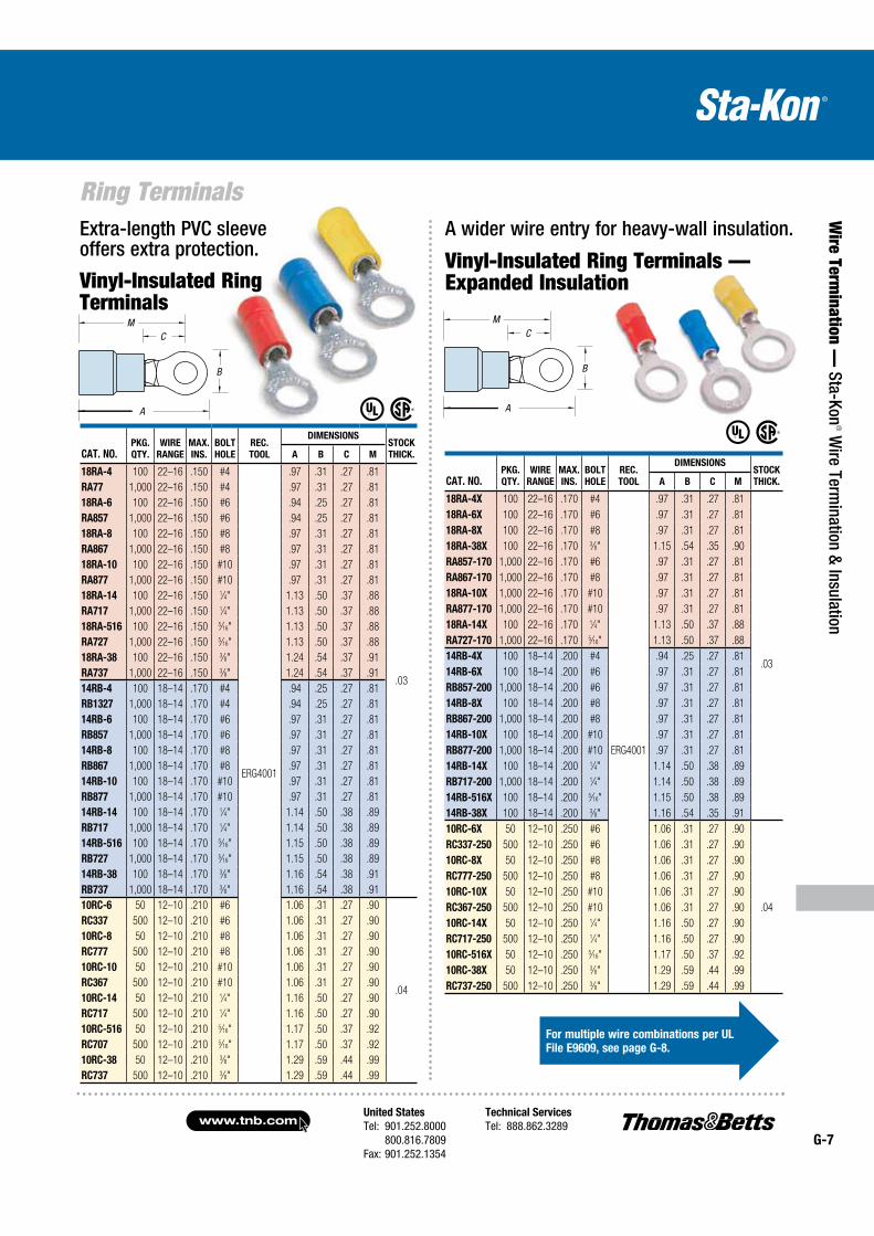
Extra-length PVC sleeve offers extra protection.
Vinyl-Insulated Ring Terminals
Vinyl-Insulated Ring Terminals — Expanded Insulation
A wider wire entry for heavy-wall insulation.
CAT. NO.PKG.
QTY.
WIRE
RANGE
MAX.
INS.
BOLT
HOLE
REC.
TOOL
DIMENSIONSSTOCK
THICK.A B C M
18RA-4 100 22–16 .150 #4
ERG4001
.97 .31 .27 .81
.03
RA77 1,000 22–16 .150 #4 .97 .31 .27 .81
18RA-6 100 22–16 .150 #6 .94 .25 .27 .81
RA857 1,000 22–16 .150 #6 .94 .25 .27 .81
18RA-8 100 22–16 .150 #8 .97 .31 .27 .81
RA867 1,000 22–16 .150 #8 .97 .31 .27 .81
18RA-10 100 22–16 .150 #10 .97 .31 .27 .81
RA877 1,000 22–16 .150 #10 .97 .31 .27 .81
18RA-14 100 22–16 .150 1⁄4" 1.13 .50 .37 .88
RA717 1,000 22–16 .150 1⁄4" 1.13 .50 .37 .88
18RA-516 100 22–16 .150 5⁄16" 1.13 .50 .37 .88
RA727 1,000 22–16 .150 5⁄16" 1.13 .50 .37 .88
18RA-38 100 22–16 .150 3⁄8" 1.24 .54 .37 .91
RA737 1,000 22–16 .150 3⁄8" 1.24 .54 .37 .91
14RB-4 100 18–14 .170 #4 .94 .25 .27 .81
RB1327 1,000 18–14 .170 #4 .94 .25 .27 .81
14RB-6 100 18–14 .170 #6 .97 .31 .27 .81
RB857 1,000 18–14 .170 #6 .97 .31 .27 .81
14RB-8 100 18–14 .170 #8 .97 .31 .27 .81
RB867 1,000 18–14 .170 #8 .97 .31 .27 .81
14RB-10 100 18–14 .170 #10 .97 .31 .27 .81
RB877 1,000 18–14 .170 #10 .97 .31 .27 .81
14RB-14 100 18–14 .170 1⁄4" 1.14 .50 .38 .89
RB717 1,000 18–14 .170 1⁄4" 1.14 .50 .38 .89
14RB-516 100 18–14 .170 5⁄16" 1.15 .50 .38 .89
RB727 1,000 18–14 .170 5⁄16" 1.15 .50 .38 .89
14RB-38 100 18–14 .170 3⁄8" 1.16 .54 .38 .91
RB737 1,000 18–14 .170 3⁄8" 1.16 .54 .38 .91
10RC-6 50 12–10 .210 #6 1.06 .31 .27 .90
.04
RC337 500 12–10 .210 #6 1.06 .31 .27 .90
10RC-8 50 12–10 .210 #8 1.06 .31 .27 .90
RC777 500 12–10 .210 #8 1.06 .31 .27 .90
10RC-10 50 12–10 .210 #10 1.06 .31 .27 .90
RC367 500 12–10 .210 #10 1.06 .31 .27 .90
10RC-14 50 12–10 .210 1⁄4" 1.16 .50 .27 .90
RC717 500 12–10 .210 1⁄4" 1.16 .50 .27 .90
10RC-516 50 12–10 .210 5⁄16" 1.17 .50 .37 .92
RC707 500 12–10 .210 5⁄16" 1.17 .50 .37 .92
10RC-38 50 12–10 .210 3⁄8" 1.29 .59 .44 .99
RC737 500 12–10 .210 3⁄8" 1.29 .59 .44 .99
CAT. NO.PKG.
QTY.
WIRE
RANGE
MAX.
INS.
BOLT
HOLE
REC.
TOOL
DIMENSIONSSTOCK
THICK.A B C M
18RA-4X 100 22–16 .170 #4 .97 .31 .27 .81
18RA-6X 100 22–16 .170 #6
ERG4001
.97 .31 .27 .81
.03
18RA-8X 100 22–16 .170 #8 .97 .31 .27 .81
18RA-38X 100 22–16 .170 3⁄8" 1.15 .54 .35 .90
RA857-170 1,000 22–16 .170 #6 .97 .31 .27 .81
RA867-170 1,000 22–16 .170 #8 .97 .31 .27 .81
18RA-10X 1,000 22–16 .170 #10 .97 .31 .27 .81
RA877-170 1,000 22–16 .170 #10 .97 .31 .27 .81
18RA-14X 100 22–16 .170 1⁄4" 1.13 .50 .37 .88
RA727-170 1,000 22–16 .170 5⁄16" 1.13 .50 .37 .88
14RB-4X 100 18–14 .200 #4 .94 .25 .27 .81
14RB-6X 100 18–14 .200 #6 .97 .31 .27 .81
RB857-200 1,000 18–14 .200 #6 .97 .31 .27 .81
14RB-8X 100 18–14 .200 #8 .97 .31 .27 .81
RB867-200 1,000 18–14 .200 #8 .97 .31 .27 .81
14RB-10X 100 18–14 .200 #10 .97 .31 .27 .81
RB877-200 1,000 18–14 .200 #10 .97 .31 .27 .81
14RB-14X 100 18–14 .200 1⁄4" 1.14 .50 .38 .89
RB717-200 1,000 18–14 .200 1⁄4" 1.14 .50 .38 .89
14RB-516X 100 18–14 .200 5⁄16" 1.15 .50 .38 .89
14RB-38X 100 18–14 .200 3⁄8" 1.16 .54 .35 .91
10RC-6X 50 12–10 .250 #6 1.06 .31 .27 .90
.04
RC337-250 500 12–10 .250 #6 1.06 .31 .27 .90
10RC-8X 50 12–10 .250 #8 1.06 .31 .27 .90
RC777-250 500 12–10 .250 #8 1.06 .31 .27 .90
10RC-10X 50 12–10 .250 #10 1.06 .31 .27 .90
RC367-250 500 12–10 .250 #10 1.06 .31 .27 .90
10RC-14X 50 12–10 .250 1⁄4" 1.16 .50 .27 .90
RC717-250 500 12–10 .250 1⁄4" 1.16 .50 .27 .90
10RC-516X 50 12–10 .250 5⁄16" 1.17 .50 .37 .92
10RC-38X 50 12–10 .250 3⁄8" 1.29 .59 .44 .99
RC737-250 500 12–10 .250 3⁄8" 1.29 .59 .44 .99
For multiple wire combinations per UL
File E9609, see page G-8.
www.tnb.comUnited States
Tel: 901.252.8000 800.816.7809Fax: 901.252.1354
Technical Services
Tel: 888.862.3289G-8
Ring Terminals
Wir
e Te
rmin
atio
n —
Sta
-Kon
® W
ire T
erm
inat
ion
& In
sula
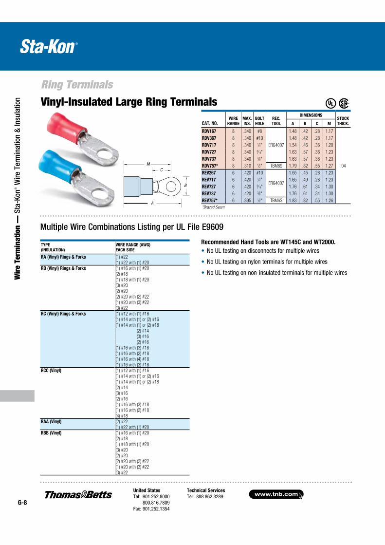
tion Vinyl-Insulated Large Ring Terminals
CAT. NO.WIRE
RANGE
MAX.
INS.
BOLT
HOLE
REC.
TOOL
DIMENSIONSSTOCK
THICK.A B C M
RDV167 8 .340 #8
ERG4007
1.48 .42 .28 1.17
.04
RDV367 8 .340 #10 1.48 .42 .28 1.17
RDV717 8 .340 1⁄4" 1.54 .46 .36 1.20
RDV727 8 .340 5⁄16" 1.63 .57 .36 1.23
RDV737 8 .340 3⁄8" 1.63 .57 .36 1.23
RDV757* 8 .310 1⁄2" TBM6S 1.79 .82 .55 1.27
REV267 6 .420 #10
ERG4007
1.65 .45 .28 1.23
REV717 6 .420 1⁄4" 1.65 .49 .28 1.23
REV727 6 .420 5⁄16" 1.76 .61 .34 1.30
REV737 6 .420 3⁄8" 1.76 .61 .34 1.30
REV757* 6 .395 1⁄2" TBM6S 1.83 .82 .55 1.26
*Brazed Seam
M
B
A
CM
Multiple Wire Combinations Listing per UL File E9609
TYPE
(INSULATION)
WIRE RANGE (AWG)
EACH SIDE
RA (Vinyl) Rings & Forks (1) #22(1) #22 with (1) #20
RB (Vinyl) Rings & Forks (1) #16 with (1) #20(2) #18(1) #18 with (1) #20(3) #20(2) #20(2) #20 with (2) #22(1) #20 with (3) #22(3) #22
RC (Vinyl) Rings & Forks (1) #12 with (1) #16(1) #14 with (1) or (2) #16(1) #14 with (1) or (2) #18 (2) #14 (3) #16 (2) #16(1) #16 with (3) #18(1) #16 with (2) #18(1) #16 with (4) #18(1) #16 with (3) #18
RCC (Vinyl) (1) #12 with (1) #16(1) #14 with (1) or (2) #16(1) #14 with (1) or (2) #18(2) #14(3) #16(2) #16(1) #16 with (3) #18(1) #16 with (2) #18(4) #18
RAA (Vinyl) (2) #22(1) #22 with (1) #20
RBB (Vinyl) (1) #16 with (1) #20(2) #18(1) #18 with (1) #20(3) #20(2) #20(2) #20 with (2) #22(1) #20 with (3) #22(3) #22
Recommended Hand Tools are WT145C and WT2000.
No UL testing on disconnects for multiple wires
No UL testing on nylon terminals for multiple wires
No UL testing on non-insulated terminals for multiple wires
United States
Tel: 901.252.8000 800.816.7809Fax: 901.252.1354
Technical Services
Tel: 888.862.3289www.tnb.com
G-9
Ring Terminals
Wire Term
ination — Sta-Kon
® Wire Term
ination & Insulation
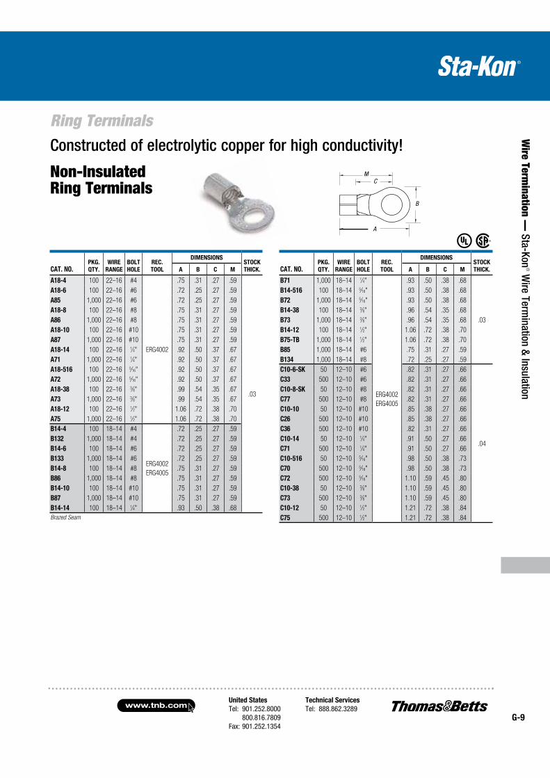
Constructed of electrolytic copper for high conductivity!
Non-Insulated Ring Terminals
CAT. NO.PKG.
QTY.
WIRE
RANGE
BOLT
HOLE
REC.
TOOL
DIMENSIONSSTOCK
THICK.A B C M
A18-4 100 22–16 #4
ERG4002
.75 .31 .27 .59
.03
A18-6 100 22–16 #6 .72 .25 .27 .59
A85 1,000 22–16 #6 .72 .25 .27 .59
A18-8 100 22–16 #8 .75 .31 .27 .59
A86 1,000 22–16 #8 .75 .31 .27 .59
A18-10 100 22–16 #10 .75 .31 .27 .59
A87 1,000 22–16 #10 .75 .31 .27 .59
A18-14 100 22–16 1⁄4" .92 .50 .37 .67
A71 1,000 22–16 1⁄4" .92 .50 .37 .67
A18-516 100 22–16 5⁄16" .92 .50 .37 .67
A72 1,000 22–16 5⁄16" .92 .50 .37 .67
A18-38 100 22–16 3⁄8" .99 .54 .35 .67
A73 1,000 22–16 3⁄8" .99 .54 .35 .67
A18-12 100 22–16 1⁄2" 1.06 .72 .38 .70
A75 1,000 22–16 1⁄2" 1.06 .72 .38 .70
B14-4 100 18–14 #4
ERG4002
ERG4005
.72 .25 .27 .59
B132 1,000 18–14 #4 .72 .25 .27 .59
B14-6 100 18–14 #6 .72 .25 .27 .59
B133 1,000 18–14 #6 .72 .25 .27 .59
B14-8 100 18–14 #8 .75 .31 .27 .59
B86 1,000 18–14 #8 .75 .31 .27 .59
B14-10 100 18–14 #10 .75 .31 .27 .59
B87 1,000 18–14 #10 .75 .31 .27 .59
B14-14 100 18–14 1⁄4" .93 .50 .38 .68
Brazed Seam
CAT. NO.PKG.
QTY.
WIRE
RANGE
BOLT
HOLE
REC.
TOOL
DIMENSIONSSTOCK
THICK.A B C M
B71 1,000 18–14 1⁄4"
ERG4002
ERG4005
.93 .50 .38 .68
.03
B14-516 100 18–14 5⁄16" .93 .50 .38 .68
B72 1,000 18–14 5⁄16" .93 .50 .38 .68
B14-38 100 18–14 3⁄8" .96 .54 .35 .68
B73 1,000 18–14 3⁄8" .96 .54 .35 .68
B14-12 100 18–14 1⁄2" 1.06 .72 .38 .70
B75-TB 1,000 18–14 1⁄2" 1.06 .72 .38 .70
B85 1,000 18–14 #6 .75 .31 .27 .59
B134 1,000 18–14 #8 .72 .25 .27 .59
C10-6-SK 50 12–10 #6 .82 .31 .27 .66
.04
C33 500 12–10 #6 .82 .31 .27 .66
C10-8-SK 50 12–10 #8 .82 .31 .27 .66
C77 500 12–10 #8 .82 .31 .27 .66
C10-10 50 12–10 #10 .85 .38 .27 .66
C26 500 12–10 #10 .85 .38 .27 .66
C36 500 12–10 #10 .82 .31 .27 .66
C10-14 50 12–10 1⁄4" .91 .50 .27 .66
C71 500 12–10 1⁄4" .91 .50 .27 .66
C10-516 50 12–10 5⁄16" .98 .50 .38 .73
C70 500 12–10 5⁄16" .98 .50 .38 .73
C72 500 12–10 5⁄16" 1.10 .59 .45 .80
C10-38 50 12–10 3⁄8" 1.10 .59 .45 .80
C73 500 12–10 3⁄8" 1.10 .59 .45 .80
C10-12 50 12–10 1⁄2" 1.21 .72 .38 .84
C75 500 12–10 1⁄2" 1.21 .72 .38 .84
B
A
CM
www.tnb.comUnited States
Tel: 901.252.8000 800.816.7809Fax: 901.252.1354
Technical Services
Tel: 888.862.3289G-10
Ring Terminals
Wir
e Te
rmin
atio
n —
Sta
-Kon
® W
ire T
erm
inat
ion
& In
sula
tion
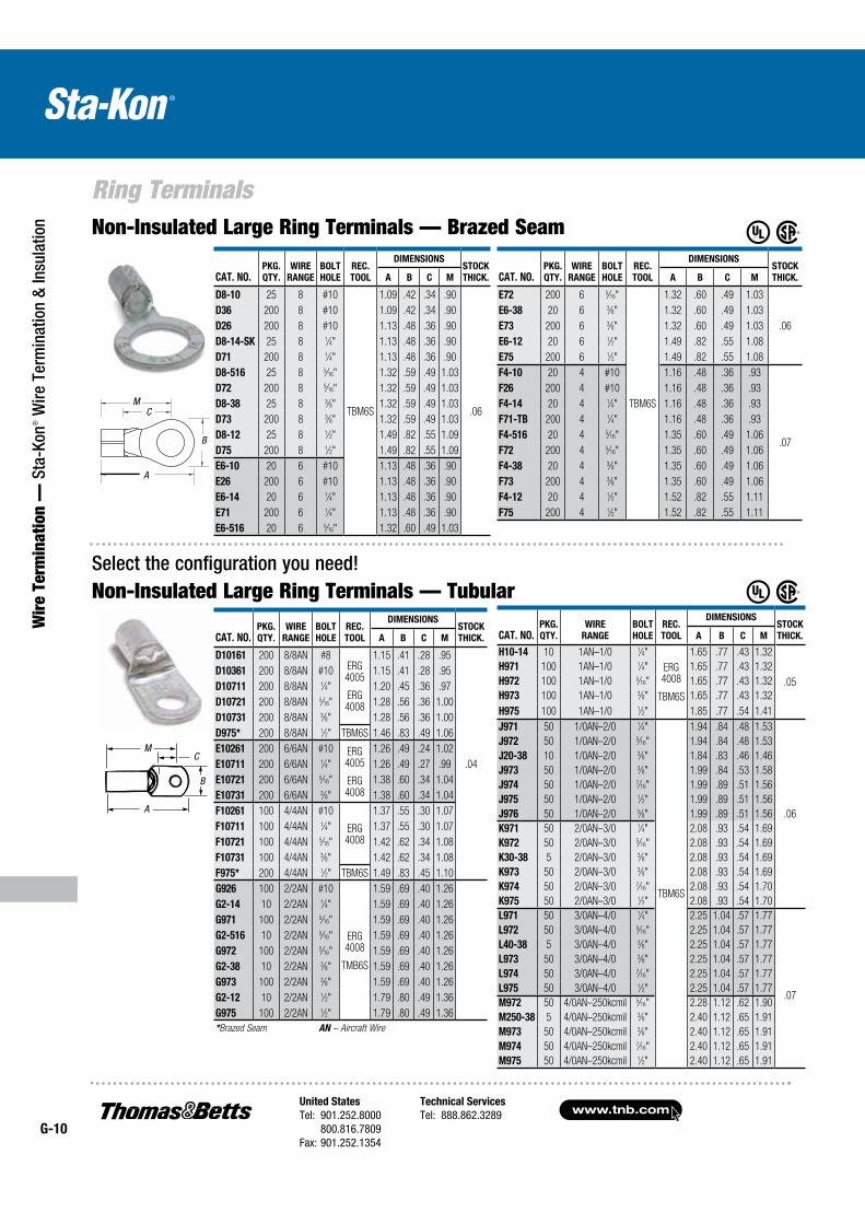
Select the configuration you need! Non-Insulated Large Ring Terminals — Tubular
Non-Insulated Large Ring Terminals — Brazed Seam
CAT. NO.PKG.
QTY.
WIRE
RANGE
BOLT
HOLE
REC.
TOOL
DIMENSIONSSTOCK
THICK.A B C M
D10161 200 8/8AN #8ERG4005
ERG 4008
1.15 .41 .28 .95
.04
D10361 200 8/8AN #10 1.15 .41 .28 .95
D10711 200 8/8AN 1⁄4" 1.20 .45 .36 .97
D10721 200 8/8AN 5⁄16" 1.28 .56 .36 1.00
D10731 200 8/8AN 3⁄8" 1.28 .56 .36 1.00
D975* 200 8/8AN 1⁄2" TBM6S 1.46 .83 .49 1.06
E10261 200 6/6AN #10 ERG4005
ERG 4008
1.26 .49 .24 1.02
E10711 200 6/6AN 1⁄4" 1.26 .49 .27 .99
E10721 200 6/6AN 5⁄16" 1.38 .60 .34 1.04
E10731 200 6/6AN 3⁄8" 1.38 .60 .34 1.04
F10261 100 4/4AN #10
ERG 4008
1.37 .55 .30 1.07
F10711 100 4/4AN 1⁄4" 1.37 .55 .30 1.07
F10721 100 4/4AN 5⁄16" 1.42 .62 .34 1.08
F10731 100 4/4AN 3⁄8" 1.42 .62 .34 1.08
F975* 200 4/4AN 1⁄2" TBM6S 1.49 .83 .45 1.10
G926 100 2/2AN #10
ERG 4008
TMB6S
1.59 .69 .40 1.26
G2-14 10 2/2AN 1⁄4" 1.59 .69 .40 1.26
G971 100 2/2AN 5⁄16" 1.59 .69 .40 1.26
G2-516 10 2/2AN 5⁄16" 1.59 .69 .40 1.26
G972 100 2/2AN 5⁄16" 1.59 .69 .40 1.26
G2-38 10 2/2AN 3⁄8" 1.59 .69 .40 1.26
G973 100 2/2AN 3⁄8" 1.59 .69 .40 1.26
G2-12 10 2/2AN 1⁄2" 1.79 .80 .49 1.36
G975 100 2/2AN 1⁄2" 1.79 .80 .49 1.36
*Brazed Seam AN – Aircraft Wire
CAT. NO.PKG.
QTY.
WIRE
RANGE
BOLT
HOLE
REC.
TOOL
DIMENSIONSSTOCK
THICK.A B C M
D8-10 25 8 #10
TBM6S
1.09 .42 .34 .90
.06
D36 200 8 #10 1.09 .42 .34 .90
D26 200 8 #10 1.13 .48 .36 .90
D8-14-SK 25 8 1⁄4" 1.13 .48 .36 .90
D71 200 8 1⁄4" 1.13 .48 .36 .90
D8-516 25 8 5⁄16" 1.32 .59 .49 1.03
D72 200 8 5⁄16" 1.32 .59 .49 1.03
D8-38 25 8 3⁄8" 1.32 .59 .49 1.03
D73 200 8 3⁄8" 1.32 .59 .49 1.03
D8-12 25 8 1⁄2" 1.49 .82 .55 1.09
D75 200 8 1⁄2" 1.49 .82 .55 1.09
E6-10 20 6 #10 1.13 .48 .36 .90
E26 200 6 #10 1.13 .48 .36 .90
E6-14 20 6 1⁄4" 1.13 .48 .36 .90
E71 200 6 1⁄4" 1.13 .48 .36 .90
E6-516 20 6 5⁄16" 1.32 .60 .49 1.03
CAT. NO.PKG.
QTY.
WIRE
RANGE
BOLT
HOLE
REC.
TOOL
DIMENSIONSSTOCK
THICK.A B C M
E72 200 6 5⁄16"
TBM6S
1.32 .60 .49 1.03
.06
E6-38 20 6 3⁄8" 1.32 .60 .49 1.03
E73 200 6 3⁄8" 1.32 .60 .49 1.03
E6-12 20 6 1⁄2" 1.49 .82 .55 1.08
E75 200 6 1⁄2" 1.49 .82 .55 1.08
F4-10 20 4 #10 1.16 .48 .36 .93
.07
F26 200 4 #10 1.16 .48 .36 .93
F4-14 20 4 1⁄4" 1.16 .48 .36 .93
F71-TB 200 4 1⁄4" 1.16 .48 .36 .93
F4-516 20 4 5⁄16" 1.35 .60 .49 1.06
F72 200 4 5⁄16" 1.35 .60 .49 1.06
F4-38 20 4 3⁄8" 1.35 .60 .49 1.06
F73 200 4 3⁄8" 1.35 .60 .49 1.06
F4-12 20 4 1⁄2" 1.52 .82 .55 1.11
F75 200 4 1⁄2" 1.52 .82 .55 1.11
CAT. NO.PKG.
QTY.
WIRE
RANGE
BOLT
HOLE
REC.
TOOL
DIMENSIONSSTOCK
THICK.A B C M
H10-14 10 1AN–1/0 1⁄4"
ERG 4008
TBM6S
1.65 .77 .43 1.32
.05
H971 100 1AN–1/0 1⁄4" 1.65 .77 .43 1.32
H972 100 1AN–1/0 5⁄16" 1.65 .77 .43 1.32
H973 100 1AN–1/0 3⁄8" 1.65 .77 .43 1.32
H975 100 1AN–1/0 1⁄2" 1.85 .77 .54 1.41
J971 50 1/0AN–2/0 1⁄4"
TBM6S
1.94 .84 .48 1.53
.06
J972 50 1/0AN–2/0 5⁄16" 1.94 .84 .48 1.53
J20-38 10 1/0AN–2/0 3⁄8" 1.84 .83 .46 1.46
J973 50 1/0AN–2/0 3⁄8" 1.99 .84 .53 1.58
J974 50 1/0AN–2/0 7⁄16" 1.99 .89 .51 1.56
J975 50 1/0AN–2/0 1⁄2" 1.99 .89 .51 1.56
J976 50 1/0AN–2/0 5⁄8" 1.99 .89 .51 1.56
K971 50 2/0AN–3/0 1⁄4" 2.08 .93 .54 1.69
K972 50 2/0AN–3/0 5⁄16" 2.08 .93 .54 1.69
K30-38 5 2/0AN–3/0 3⁄8" 2.08 .93 .54 1.69
K973 50 2/0AN–3/0 3⁄8" 2.08 .93 .54 1.69
K974 50 2/0AN–3/0 7⁄16" 2.08 .93 .54 1.70
K975 50 2/0AN–3/0 1⁄2" 2.08 .93 .54 1.70
L971 50 3/0AN–4/0 1⁄4" 2.25 1.04 .57 1.77
L972 50 3/0AN–4/0 5⁄16" 2.25 1.04 .57 1.77
.07
L40-38 5 3/0AN–4/0 3⁄8" 2.25 1.04 .57 1.77
L973 50 3/0AN–4/0 3⁄8" 2.25 1.04 .57 1.77
L974 50 3/0AN–4/0 7⁄16" 2.25 1.04 .57 1.77
L975 50 3/0AN–4/0 1⁄2" 2.25 1.04 .57 1.77
M972 50 4/0AN–250kcmil 5⁄16" 2.28 1.12 .62 1.90
M250-38 5 4/0AN–250kcmil 3⁄8" 2.40 1.12 .65 1.91
M973 50 4/0AN–250kcmil 3⁄8" 2.40 1.12 .65 1.91
M974 50 4/0AN–250kcmil 7⁄16" 2.40 1.12 .65 1.91
M975 50 4/0AN–250kcmil 1⁄2" 2.40 1.12 .65 1.91
B
A
CM
A
MC
BB
A
CM
United States
Tel: 901.252.8000 800.816.7809Fax: 901.252.1354
Technical Services
Tel: 888.862.3289www.tnb.com
G-11
Ring Terminals
Wire Term
ination — Sta-Kon
® Wire Term
ination & Insulation
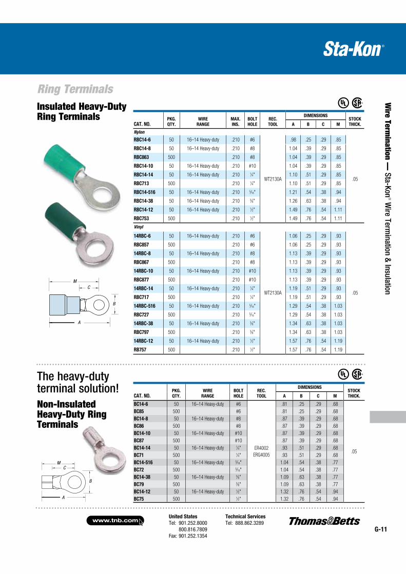
The heavy-duty terminal solution!
Insulated Heavy-Duty Ring Terminals
Non-Insulated Heavy-Duty Ring Terminals
M
B
A
CM
CAT. NO.PKG.
QTY.
WIRE
RANGE
BOLT
HOLE
REC.
TOOL
DIMENSIONSSTOCK
THICK.A B C M
BC14-6 50 16–14 Heavy-duty #6
ER4002
ERG4005
.81 .25 .29 .68
.05
BC85 500 #6 .81 .25 .29 .68
BC14-8 50 16–14 Heavy-duty #8 .87 .39 .29 .68
BC86 500 #8 .87 .39 .29 .68
BC14-10 50 16–14 Heavy-duty #10 .87 .39 .29 .68
BC87 500 #10 .87 .39 .29 .68
BC14-14 50 16–14 Heavy-duty 1⁄4" .93 .51 .29 .68
BC71 500 1⁄4" .93 .51 .29 .68
BC14-516 50 16–14 Heavy-duty 5⁄16" 1.04 .54 .38 .77
BC72 500 5⁄16" 1.04 .54 .38 .77
BC14-38 50 16–14 Heavy-duty 3⁄8" 1.09 .63 .38 .77
BC79 500 3⁄8" 1.09 .63 .38 .77
BC14-12 50 16–14 Heavy-duty 1⁄2" 1.32 .76 .54 .94
BC75 500 1⁄2" 1.32 .76 .54 .94
CAT. NO.PKG.
QTY.
WIRE
RANGE
MAX.
INS.
BOLT
HOLE
REC.
TOOL
DIMENSIONSSTOCK
THICK.A B C M
Nylon
RBC14-6 50 16–14 Heavy-duty .210 #6
WT2130A
.98 .25 .29 .85
.05
RBC14-8 50 16–14 Heavy-duty .210 #8 1.04 .39 .29 .85
RBC863 500 .210 #8 1.04 .39 .29 .85
RBC14-10 50 16–14 Heavy-duty .210 #10 1.04 .39 .29 .85
RBC14-14 50 16–14 Heavy-duty .210 1⁄4" 1.10 .51 .29 .85
RBC713 500 .210 1⁄4" 1.10 .51 .29 .85
RBC14-516 50 16–14 Heavy-duty .210 5⁄16" 1.21 .54 .38 .94
RBC14-38 50 16–14 Heavy-duty .210 3⁄8" 1.26 .63 .38 .94
RBC14-12 50 16–14 Heavy-duty .210 1⁄2" 1.49 .76 .54 1.11
RBC753 500 .210 1⁄2" 1.49 .76 .54 1.11
Vinyl
14RBC-6 50 16–14 Heavy-duty .210 #6
WT2130A
1.06 .25 .29 .93
.05
RBC857 500 .210 #6 1.06 .25 .29 .93
14RBC-8 50 16–14 Heavy-duty .210 #8 1.13 .39 .29 .93
RBC867 500 .210 #8 1.13 .39 .29 .93
14RBC-10 50 16–14 Heavy-duty .210 #10 1.13 .39 .29 .93
RBC877 500 .210 #10 1.13 .39 .29 .93
14RBC-14 50 16–14 Heavy-duty .210 1⁄4" 1.19 .51 .29 .93
RBC717 500 .210 1⁄4" 1.19 .51 .29 .93
14RBC-516 50 16–14 Heavy-duty .210 5⁄16" 1.29 .54 .38 1.03
RBC727 500 .210 5⁄16" 1.29 .54 .38 1.03
14RBC-38 50 16–14 Heavy-duty .210 3⁄8" 1.34 .63 .38 1.03
RBC797 500 .210 3⁄8" 1.34 .63 .38 1.03
14RBC-12 50 16–14 Heavy-duty .210 1⁄2" 1.57 .76 .54 1.19
RB757 500 .210 1⁄2" 1.57 .76 .54 1.19
B
A
CM
www.tnb.comUnited States
Tel: 901.252.8000 800.816.7809Fax: 901.252.1354
Technical Services
Tel: 888.862.3289G-12
Ring Terminals
Wir
e Te
rmin
atio
n —
Sta
-Kon
® W
ire T
erm
inat
ion
& In
sula
tion
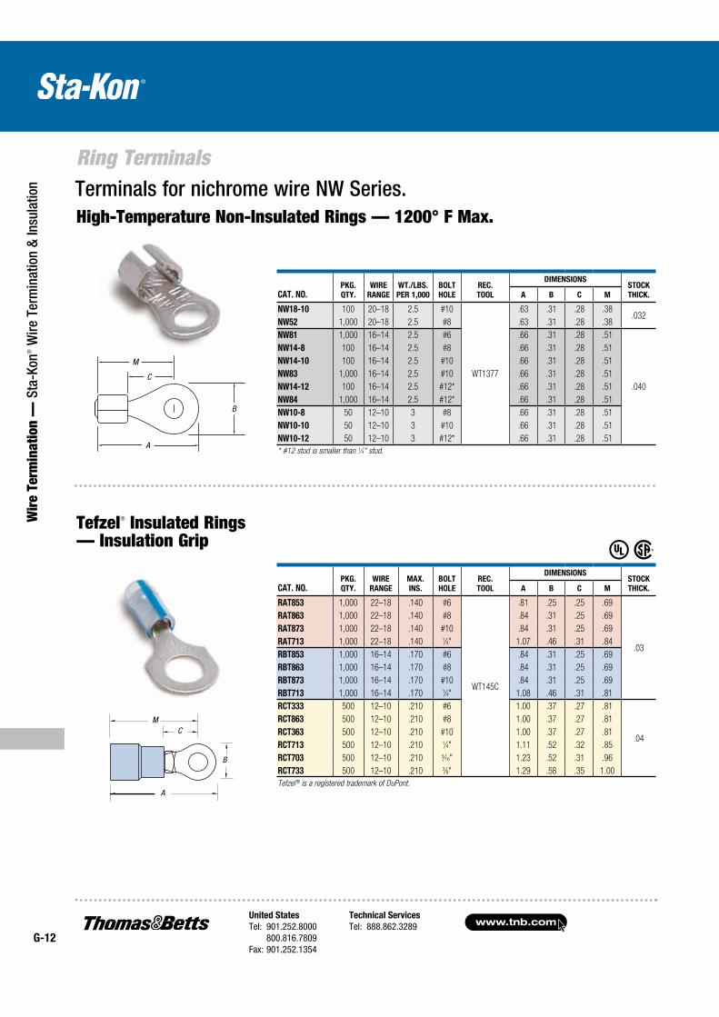
Tefzel® Insulated Rings — Insulation Grip
High-Temperature Non-Insulated Rings — 1200° F Max.Terminals for nichrome wire NW Series.
M
B
A
CM
B
A
M
CAT. NO.PKG.
QTY.
WIRE
RANGE
MAX.
INS.
BOLT
HOLE
REC.
TOOL
DIMENSIONSSTOCK
THICK.A B C M
RAT853 1,000 22–18 .140 #6
WT145C
.81 .25 .25 .69
.03
RAT863 1,000 22–18 .140 #8 .84 .31 .25 .69
RAT873 1,000 22–18 .140 #10 .84 .31 .25 .69
RAT713 1,000 22–18 .140 1⁄4" 1.07 .46 .31 .84
RBT853 1,000 16–14 .170 #6 .84 .31 .25 .69
RBT863 1,000 16–14 .170 #8 .84 .31 .25 .69
RBT873 1,000 16–14 .170 #10 .84 .31 .25 .69
RBT713 1,000 16–14 .170 1⁄4" 1.08 .46 .31 .81
RCT333 500 12–10 .210 #6 1.00 .37 .27 .81
.04
RCT863 500 12–10 .210 #8 1.00 .37 .27 .81
RCT363 500 12–10 .210 #10 1.00 .37 .27 .81
RCT713 500 12–10 .210 1⁄4" 1.11 .52 .32 .85
RCT703 500 12–10 .210 5⁄16" 1.23 .52 .31 .96
RCT733 500 12–10 .210 3⁄8" 1.29 .58 .35 1.00
Tefzel ® is a registered trademark of DuPont.
CAT. NO.PKG.
QTY.
WIRE
RANGE
WT./LBS.
PER 1,000
BOLT
HOLE
REC.
TOOL
DIMENSIONSSTOCK
THICK.A B C M
NW18-10 100 20–18 2.5 #10
WT1377
.63 .31 .28 .38.032
NW52 1,000 20–18 2.5 #8 .63 .31 .28 .38
NW81 1,000 16–14 2.5 #6 .66 .31 .28 .51
.040
NW14-8 100 16–14 2.5 #8 .66 .31 .28 .51
NW14-10 100 16–14 2.5 #10 .66 .31 .28 .51
NW83 1,000 16–14 2.5 #10 .66 .31 .28 .51
NW14-12 100 16–14 2.5 #12* .66 .31 .28 .51
NW84 1,000 16–14 2.5 #12* .66 .31 .28 .51
NW10-8 50 12–10 3 #8 .66 .31 .28 .51
NW10-10 50 12–10 3 #10 .66 .31 .28 .51
NW10-12 50 12–10 3 #12* .66 .31 .28 .51
* #12 stud is smaller than 1⁄4" stud.
C
United States
Tel: 901.252.8000 800.816.7809Fax: 901.252.1354
Technical Services
Tel: 888.862.3289www.tnb.com
G-13
Ring Terminals
Wire Term
ination — Sta-Kon
® Wire Term
ination & Insulation
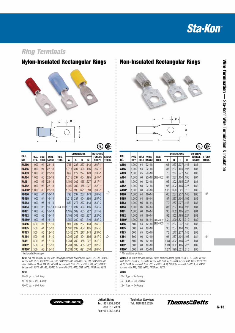
Nylon-Insulated Rectangular Rings Non-Insulated Rectangular Rings
CAT.
NO.PKG.
QTY.
BOLT
HOLE
WIRE
RANGE
REC.
TOOL
DIMENSIONS BU-SHIPS
TONGUE
SHAPE
STOCK
THICK.A B C M
RA486 1,000 #4 22–18
ERG4001
.796 .237 .237 .143 L86P-1
.03
RA485 1,000 #4 22–18 1.015 .237 .404 .195 L85P-1
RA483 1,000 #5 22–18 .859 .277 .277 .143 L83P-1
RA484 1,000 #6 22–18 1.015 .237 .404 .195 L84P-1
RA481 1,000 #6 22–18 1.109 .302 .465 .227 L81P-1
RA482 1,000 #8 22–18 1.109 .302 .465 .227 L82P-1
RA480* 1,000 #8 22–18 1.359 .390 .621 .310 L80P-1
RB486 1,000 #4 16–14 .796 .237 .237 .143 L86P-2
RB485 1,000 #4 16–14 1.015 .237 .404 .195 L85P-2
RB483 1,000 #5 16–14 .859 .277 .277 .143 L83P-2
RB484 1,000 #6 16–14 1.015 .237 .404 .195 L84P-2
RB481 1,000 #6 16–14 1.109 .302 .465 .227 L81P-2
RB482 1,000 #8 16–14 1.109 .302 .465 .227 L82P-2
RB480* 1,000 #8 16–14 1.359 .390 .621 .310 L80P-2
RC486 500 #4 12–10 .984 .237 .237 .143 L86P-3
.04
RC485 500 #4 12–10 1.187 .237 .404 .195 L85P-3
RC483 500 #5 12–10 1.046 .277 .277 .143 L83P-3
RC484 500 #6 12–10 1.203 .237 .404 .195 L84P-3
RC481 500 #6 12–10 1.281 .302 .465 .227 L81P-3
RC482 500 #8 12–10 1.281 .302 .465 .227 L82P-3
RC480* 500 #8 12–10 1.531 .390 .621 .310 L80P-3
* Not available on tape.
Note: RA, RB, RC486 for use with BU-Ships terminal board types 26TB. RA, RB, RC485
for use with 25TB and 27TB. RA, RB, RC483 for use with 8TB. RA, RB, RC484 for use
with 10TB and 11TB. RA, RB, RC481 for use with 6TB, 7TB and 9TB. RA, RB, RC482
for use with 15TB. RA, RB, RC480 for use with 3TB, 4TB, 5TB, 16TB, 17TB and 18TB.
Note:
22–18 ga. = 1–2 Navy
16–14 ga. = 21⁄2–4 Navy
12–10 ga. = 6–9 Navy
CAT.
NO.PKG.
QTY.
BOLT
HOLE
WIRE
RANGE
REC.
TOOL
DIMENSIONS BU-SHIPS
TONGUE
SHAPE
STOCK
THICK.A B C M
A486 1,000 #4 22–18
ERG4002
.65 .237 .237 .143 L86
.03
A485 1,000 #4 22–18 .87 .237 .404 .195 L85
A483 1,000 #5 22–18 .70 .277 .277 .143 L83
A484 1,000 #6 22–18 .87 .237 .404 .195 L84
A481 1,000 #6 22–18 .96 .302 .465 .227 L81
A482 1,000 #8 22–18 .96 .302 .465 .227 L82
A480* 1,000 #8 22–18 1.21 .390 .621 .310 L80
B486 1,000 #4 16–14
ERG4002ERG4005
.65 .237 .237 .143 L86
B485 1,000 #4 16–14 .87 .237 .404 .195 L85
B483 1,000 #5 16–14 .70 .277 .277 .143 L83
B484 1,000 #6 16–14 .87 .237 .404 .195 L84
B481 1,000 #6 16–14 .96 .302 .465 .227 L81
B482 1,000 #8 16–14 .96 .302 .465 .227 L82
B480* 1,000 #8 16–14 1.21 .390 .621 .310 L80
C486 500 #4 12–10 .73 .237 .237 .143 L86
.04
C485 500 #4 12–10 .90 .237 .404 .195 L85
C483 500 #5 12–10 .76 .277 .277 .143 L83
C484 500 #6 12–10 .94 .237 .404 .195 L84
C481 500 #6 12–10 1.03 .302 .465 .227 L81
C482 500 #8 12–10 1.03 .302 .465 .227 L82
C480* 500 #8 12–10 1.27 .390 .621 .310 L80
* Not available on tape.
Note: A, B, C486 for use with BU-Ships terminal board types 26TB. A, B. C485 for use
with 25TB, 27TB. A, B, C483 for use with 8TB. A, B, C484 for use with 10TB and 11TB.
A, B, C481 for use with 6TB, 7TB and 9TB. A, B, C482 for use with 15TB. A, B, C480
for use with 3TB, 5TB, 16TB, 17TB and 18TB.
Note:
22–18 ga. = 1–2 Navy
16–14 ga. = 21⁄2–4 Navy
12–10 ga. = 6–9 Navy
A
MC
BB
A
C M
A
MC
BB
A
C M
www.tnb.comUnited States
Tel: 901.252.8000 800.816.7809Fax: 901.252.1354
Technical Services
Tel: 888.862.3289G-14
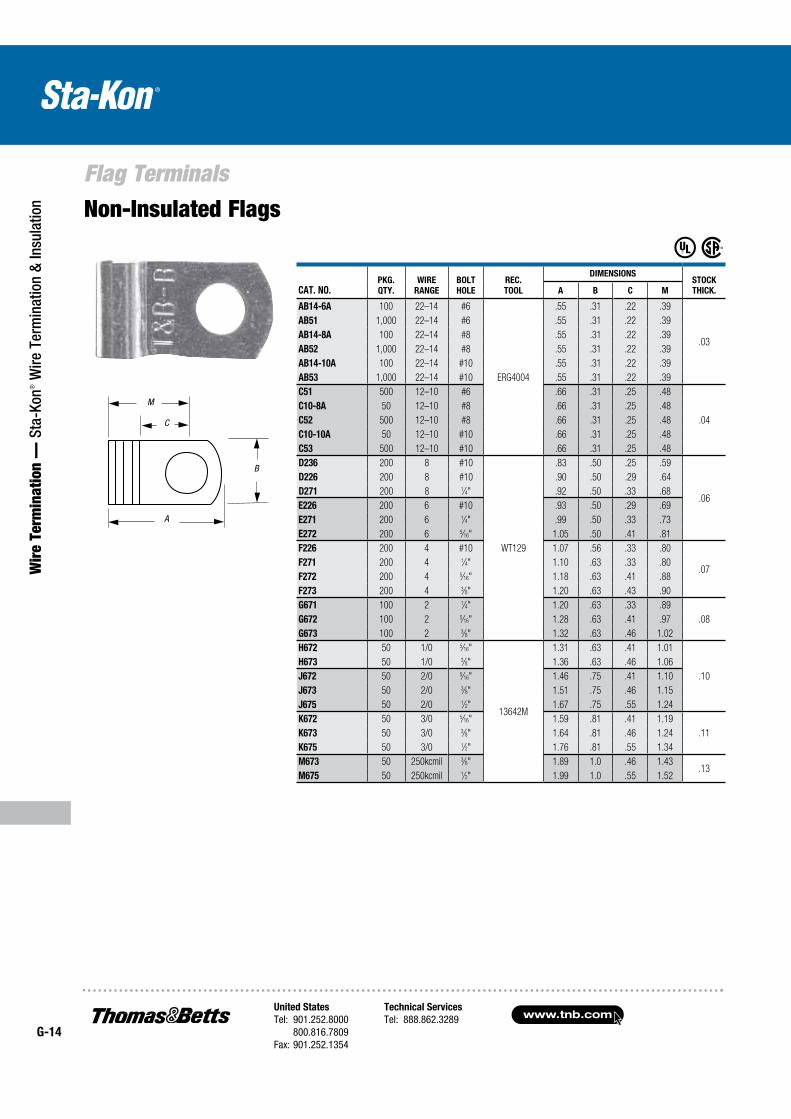
Flag Terminals
Wir
e Te
rmin
atio
n —
Sta
-Kon
® W
ire T
erm
inat
ion
& In
sula
tion Non-Insulated Flags
CAT. NO.PKG.
QTY.
WIRE
RANGE
BOLT
HOLE
REC.
TOOL
DIMENSIONSSTOCK
THICK.A B C M
AB14-6A 100 22–14 #6
ERG4004
.55 .31 .22 .39
.03
AB51 1,000 22–14 #6 .55 .31 .22 .39
AB14-8A 100 22–14 #8 .55 .31 .22 .39
AB52 1,000 22–14 #8 .55 .31 .22 .39
AB14-10A 100 22–14 #10 .55 .31 .22 .39
AB53 1,000 22–14 #10 .55 .31 .22 .39
C51 500 12–10 #6 .66 .31 .25 .48
.04
C10-8A 50 12–10 #8 .66 .31 .25 .48
C52 500 12–10 #8 .66 .31 .25 .48
C10-10A 50 12–10 #10 .66 .31 .25 .48
C53 500 12–10 #10 .66 .31 .25 .48
D236 200 8 #10
WT129
.83 .50 .25 .59
.06
D226 200 8 #10 .90 .50 .29 .64
D271 200 8 1⁄4" .92 .50 .33 .68
E226 200 6 #10 .93 .50 .29 .69
E271 200 6 1⁄4" .99 .50 .33 .73
E272 200 6 5⁄16" 1.05 .50 .41 .81
F226 200 4 #10 1.07 .56 .33 .80
.07F271 200 4 1⁄4" 1.10 .63 .33 .80
F272 200 4 5⁄16" 1.18 .63 .41 .88
F273 200 4 3⁄8" 1.20 .63 .43 .90
G671 100 2 1⁄4" 1.20 .63 .33 .89
.08G672 100 2 5⁄16" 1.28 .63 .41 .97
G673 100 2 3⁄8" 1.32 .63 .46 1.02
H672 50 1/0 5⁄16"
13642M
1.31 .63 .41 1.01
.10
H673 50 1/0 3⁄8" 1.36 .63 .46 1.06
J672 50 2/0 5⁄16" 1.46 .75 .41 1.10
J673 50 2/0 3⁄8" 1.51 .75 .46 1.15
J675 50 2/0 1⁄2" 1.67 .75 .55 1.24
K672 50 3/0 5⁄16" 1.59 .81 .41 1.19
.11K673 50 3/0 3⁄8" 1.64 .81 .46 1.24
K675 50 3/0 1⁄2" 1.76 .81 .55 1.34
M673 50 250kcmil 3⁄8" 1.89 1.0 .46 1.43.13
M675 50 250kcmil 1⁄2" 1.99 1.0 .55 1.52
A
M
C
BB
A
C
M
United States
Tel: 901.252.8000 800.816.7809Fax: 901.252.1354
Technical Services
Tel: 888.862.3289www.tnb.com
G-15
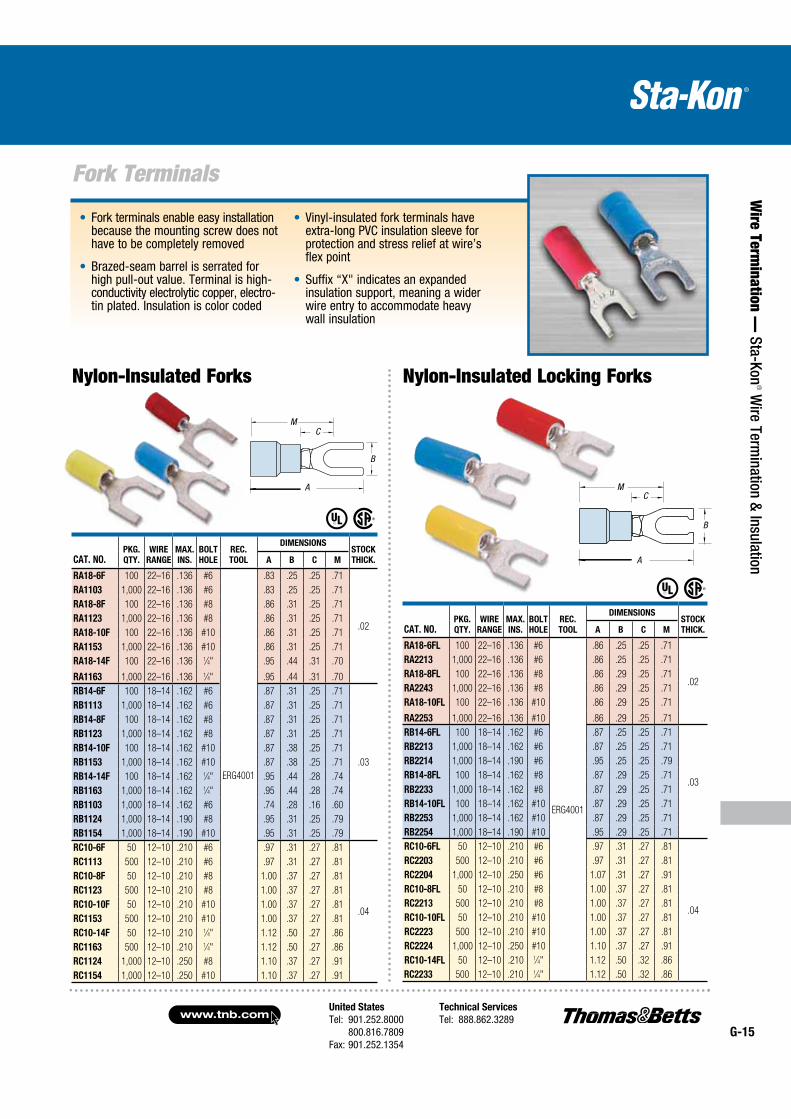
Fork Terminals
Wire Term
ination — Sta-Kon
® Wire Term
ination & Insulation
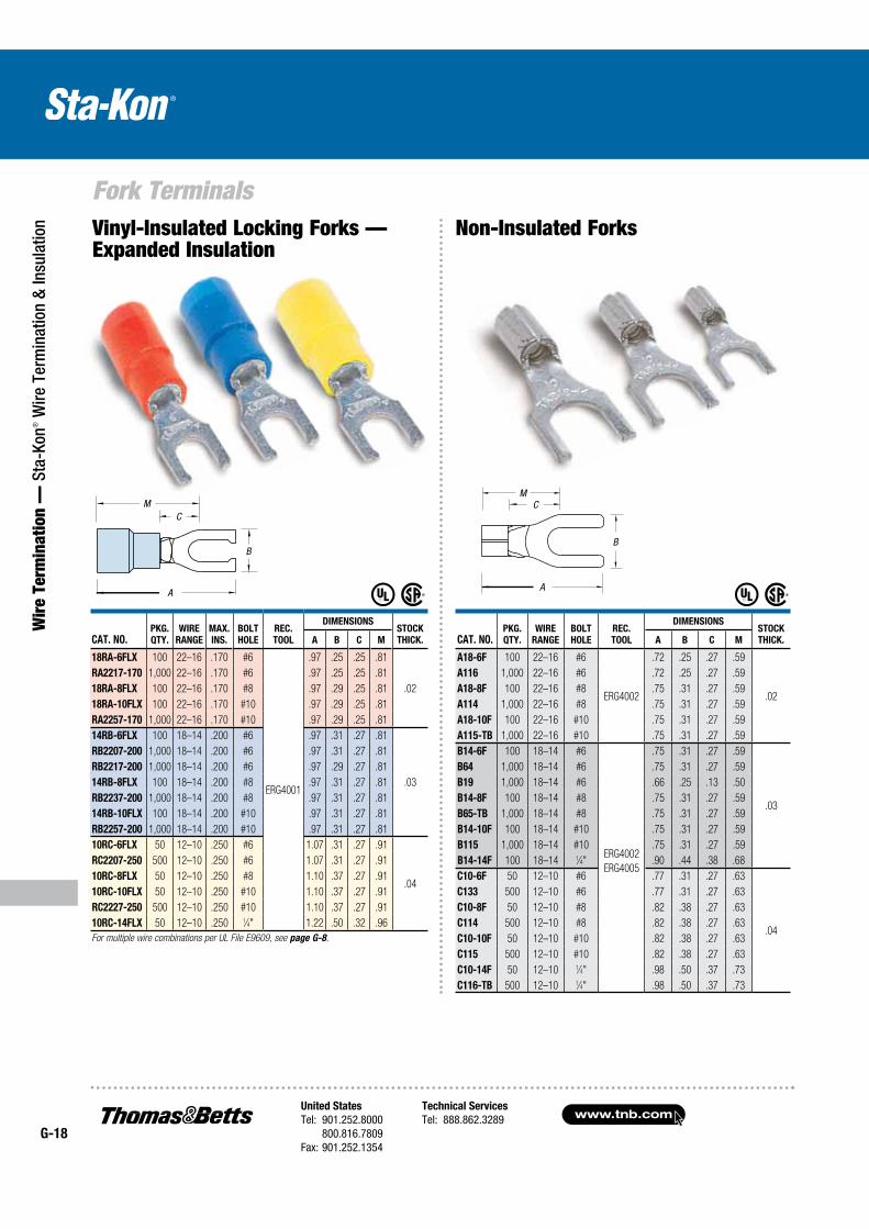
Nylon-Insulated Locking ForksNylon-Insulated Forks
B
A
CM
B
A
CM
CAT. NO.PKG.
QTY.
WIRE
RANGE
MAX.
INS.
BOLT
HOLE
REC.
TOOL
DIMENSIONSSTOCK
THICK.A B C M
RA18-6FL 100 22–16 .136 #6
ERG4001
.86 .25 .25 .71
.02
RA2213 1,000 22–16 .136 #6 .86 .25 .25 .71
RA18-8FL 100 22–16 .136 #8 .86 .29 .25 .71
RA2243 1,000 22–16 .136 #8 .86 .29 .25 .71
RA18-10FL 100 22–16 .136 #10 .86 .29 .25 .71
RA2253 1,000 22–16 .136 #10 .86 .29 .25 .71
RB14-6FL 100 18–14 .162 #6 .87 .25 .25 .71
.03
RB2213 1,000 18–14 .162 #6 .87 .25 .25 .71
RB2214 1,000 18–14 .190 #6 .95 .25 .25 .79
RB14-8FL 100 18–14 .162 #8 .87 .29 .25 .71
RB2233 1,000 18–14 .162 #8 .87 .29 .25 .71
RB14-10FL 100 18–14 .162 #10 .87 .29 .25 .71
RB2253 1,000 18–14 .162 #10 .87 .29 .25 .71
RB2254 1,000 18–14 .190 #10 .95 .29 .25 .71
RC10-6FL 50 12–10 .210 #6 .97 .31 .27 .81
.04
RC2203 500 12–10 .210 #6 .97 .31 .27 .81
RC2204 1,000 12–10 .250 #6 1.07 .31 .27 .91
RC10-8FL 50 12–10 .210 #8 1.00 .37 .27 .81
RC2213 500 12–10 .210 #8 1.00 .37 .27 .81
RC10-10FL 50 12–10 .210 #10 1.00 .37 .27 .81
RC2223 500 12–10 .210 #10 1.00 .37 .27 .81
RC2224 1,000 12–10 .250 #10 1.10 .37 .27 .91
RC10-14FL 50 12–10 .210 1⁄4" 1.12 .50 .32 .86
RC2233 500 12–10 .210 1⁄4" 1.12 .50 .32 .86
CAT. NO.PKG.
QTY.
WIRE
RANGE
MAX.
INS.
BOLT
HOLE
REC.
TOOL
DIMENSIONSSTOCK
THICK.A B C M
RA18-6F 100 22–16 .136 #6
ERG4001
.83 .25 .25 .71
.02
RA1103 1,000 22–16 .136 #6 .83 .25 .25 .71
RA18-8F 100 22–16 .136 #8 .86 .31 .25 .71
RA1123 1,000 22–16 .136 #8 .86 .31 .25 .71
RA18-10F 100 22–16 .136 #10 .86 .31 .25 .71
RA1153 1,000 22–16 .136 #10 .86 .31 .25 .71
RA18-14F 100 22–16 .136 1⁄4" .95 .44 .31 .70
RA1163 1,000 22–16 .136 1⁄4" .95 .44 .31 .70
RB14-6F 100 18–14 .162 #6 .87 .31 .25 .71
.03
RB1113 1,000 18–14 .162 #6 .87 .31 .25 .71
RB14-8F 100 18–14 .162 #8 .87 .31 .25 .71
RB1123 1,000 18–14 .162 #8 .87 .31 .25 .71
RB14-10F 100 18–14 .162 #10 .87 .38 .25 .71
RB1153 1,000 18–14 .162 #10 .87 .38 .25 .71
RB14-14F 100 18–14 .162 1⁄4" .95 .44 .28 .74
RB1163 1,000 18–14 .162 1⁄4" .95 .44 .28 .74
RB1103 1,000 18–14 .162 #6 .74 .28 .16 .60
RB1124 1,000 18–14 .190 #8 .95 .31 .25 .79
RB1154 1,000 18–14 .190 #10 .95 .31 .25 .79
RC10-6F 50 12–10 .210 #6 .97 .31 .27 .81
.04
RC1113 500 12–10 .210 #6 .97 .31 .27 .81
RC10-8F 50 12–10 .210 #8 1.00 .37 .27 .81
RC1123 500 12–10 .210 #8 1.00 .37 .27 .81
RC10-10F 50 12–10 .210 #10 1.00 .37 .27 .81
RC1153 500 12–10 .210 #10 1.00 .37 .27 .81
RC10-14F 50 12–10 .210 1⁄4" 1.12 .50 .27 .86
RC1163 500 12–10 .210 1⁄4" 1.12 .50 .27 .86
RC1124 1,000 12–10 .250 #8 1.10 .37 .27 .91
RC1154 1,000 12–10 .250 #10 1.10 .37 .27 .91
www.tnb.comUnited States
Tel: 901.252.8000 800.816.7809Fax: 901.252.1354
Technical Services
Tel: 888.862.3289G-16
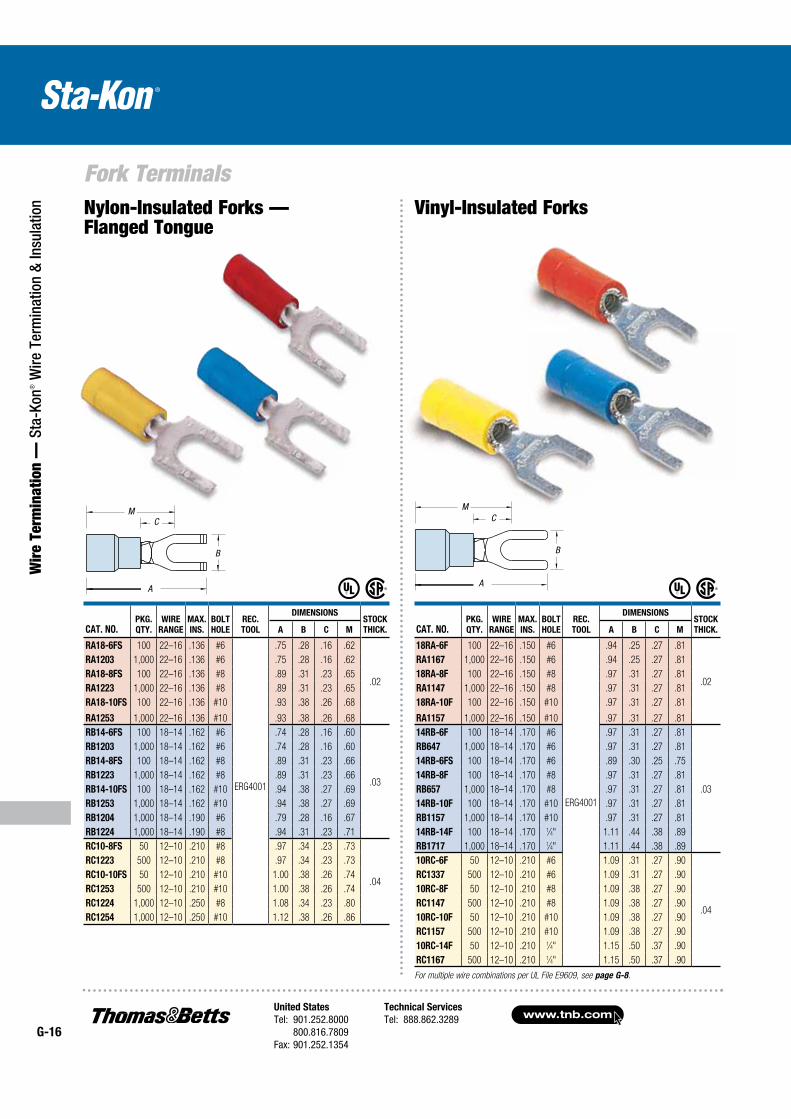
Fork Terminals
Wir
e Te
rmin
atio
n —
Sta
-Kon
® W
ire T
erm
inat
ion
& In
sula
tion
B
A
CM
Vinyl-Insulated Forks Nylon-Insulated Forks — Flanged Tongue
CAT. NO.PKG.
QTY.
WIRE
RANGE
MAX.
INS.
BOLT
HOLE
REC.
TOOL
DIMENSIONSSTOCK
THICK.A B C M
18RA-6F 100 22–16 .150 #6
ERG4001
.94 .25 .27 .81
.02
RA1167 1,000 22–16 .150 #6 .94 .25 .27 .81
18RA-8F 100 22–16 .150 #8 .97 .31 .27 .81
RA1147 1,000 22–16 .150 #8 .97 .31 .27 .81
18RA-10F 100 22–16 .150 #10 .97 .31 .27 .81
RA1157 1,000 22–16 .150 #10 .97 .31 .27 .81
14RB-6F 100 18–14 .170 #6 .97 .31 .27 .81
.03
RB647 1,000 18–14 .170 #6 .97 .31 .27 .81
14RB-6FS 100 18–14 .170 #6 .89 .30 .25 .75
14RB-8F 100 18–14 .170 #8 .97 .31 .27 .81
RB657 1,000 18–14 .170 #8 .97 .31 .27 .81
14RB-10F 100 18–14 .170 #10 .97 .31 .27 .81
RB1157 1,000 18–14 .170 #10 .97 .31 .27 .81
14RB-14F 100 18–14 .170 1⁄4" 1.11 .44 .38 .89
RB1717 1,000 18–14 .170 1⁄4" 1.11 .44 .38 .89
10RC-6F 50 12–10 .210 #6 1.09 .31 .27 .90
.04
RC1337 500 12–10 .210 #6 1.09 .31 .27 .90
10RC-8F 50 12–10 .210 #8 1.09 .38 .27 .90
RC1147 500 12–10 .210 #8 1.09 .38 .27 .90
10RC-10F 50 12–10 .210 #10 1.09 .38 .27 .90
RC1157 500 12–10 .210 #10 1.09 .38 .27 .90
10RC-14F 50 12–10 .210 1⁄4" 1.15 .50 .37 .90
RC1167 500 12–10 .210 1⁄4" 1.15 .50 .37 .90
CAT. NO.PKG.
QTY.
WIRE
RANGE
MAX.
INS.
BOLT
HOLE
REC.
TOOL
DIMENSIONSSTOCK
THICK.A B C M
RA18-6FS 100 22–16 .136 #6
ERG4001
.75 .28 .16 .62
.02
RA1203 1,000 22–16 .136 #6 .75 .28 .16 .62
RA18-8FS 100 22–16 .136 #8 .89 .31 .23 .65
RA1223 1,000 22–16 .136 #8 .89 .31 .23 .65
RA18-10FS 100 22–16 .136 #10 .93 .38 .26 .68
RA1253 1,000 22–16 .136 #10 .93 .38 .26 .68
RB14-6FS 100 18–14 .162 #6 .74 .28 .16 .60
.03
RB1203 1,000 18–14 .162 #6 .74 .28 .16 .60
RB14-8FS 100 18–14 .162 #8 .89 .31 .23 .66
RB1223 1,000 18–14 .162 #8 .89 .31 .23 .66
RB14-10FS 100 18–14 .162 #10 .94 .38 .27 .69
RB1253 1,000 18–14 .162 #10 .94 .38 .27 .69
RB1204 1,000 18–14 .190 #6 .79 .28 .16 .67
RB1224 1,000 18–14 .190 #8 .94 .31 .23 .71
RC10-8FS 50 12–10 .210 #8 .97 .34 .23 .73
.04
RC1223 500 12–10 .210 #8 .97 .34 .23 .73
RC10-10FS 50 12–10 .210 #10 1.00 .38 .26 .74
RC1253 500 12–10 .210 #10 1.00 .38 .26 .74
RC1224 1,000 12–10 .250 #8 1.08 .34 .23 .80
RC1254 1,000 12–10 .250 #10 1.12 .38 .26 .86
B
A
CM
For multiple wire combinations per UL File E9609, see page G-8.
United States
Tel: 901.252.8000 800.816.7809Fax: 901.252.1354
Technical Services
Tel: 888.862.3289www.tnb.com
G-17
Fork Terminals
Wire Term
ination — Sta-Kon
® Wire Term
ination & Insulation
Vinyl-Insulated Locking Forks
CAT. NO.PKG.
QTY.
WIRE
RANGE
MAX.
INS.
BOLT
HOLE
REC.
TOOL
DIMENSIONSSTOCK
THICK.A B C M
18RA-6FL 100 22–16 .150 #6
ERG4001
.97 .25 .25 .81
.02
RA2217 1,000 22–16 .150 #6 .97 .25 .25 .81
RA2227 1,000 22–16 .155 #6 .97 .29 — .81
18RA-8FL 100 22–16 .150 #8 .97 .29 .25 .81
RA2247 1,000 22–16 .150 #8 .97 .29 .25 .81
18RA-10FL 100 22–16 .150 #10 .97 .29 .25 .81
RA2257 1,000 22–16 .150 #10 .97 .29 .25 .81
14RB-6FL 100 18–14 .170 #6 .97 .25 .27 .81
.03
RB2207 1,000 18–14 .170 #6 .97 .25 .27 .81
RB2217 1,000 18–14 .170 #6 .97 .29 .27 .81
14RB-8FL 100 18–14 .170 #8 .97 .29 .27 .81
RB2237 1,000 18–14 .170 #8 .97 .29 .27 .81
14RB-10FL 100 18–14 .170 #10 .97 .29 .27 .81
RB2257 1,000 18–14 .170 #10 .97 .29 .27 .81
10RC-6FL 50 12–10 .220 #6 1.09 .31 .27 .90
.04
RC2207 500 12–10 .220 #6 1.09 .31 .27 .90
10RC-8FL 50 12–10 .220 #8 1.09 .37 .27 .90
RC2217 500 12–10 .220 #8 1.09 .37 .27 .90
10RC-10FL 50 12–10 .220 #10 1.09 .37 .27 .90
RC2227 500 12–10 .220 #10 1.09 .37 .27 .90
10RC-14FL 50 12–10 .220 1⁄4" 1.09 .49 .27 .90
RC2237 500 12–10 .220 1⁄4" 1.09 .49 .27 .90
CAT. NO.PKG.
QTY.
WIRE
RANGE
MAX.
INS.
BOLT
HOLE
REC.
TOOL
DIMENSIONSSTOCK
THICK.A B C M
18RA-6FX 100 22–16 .170 #6
ERG4001
.94 .25 .27 .81
.02
RA1167-170 1,000 22–16 .170 #6 .94 .25 .27 .81
18RA-8FX 100 22–16 .170 #8 .97 .31 .27 .81
RA1147-170 1,000 22–16 .170 #8 .97 .31 .27 .81
18RA-10FX 100 22–16 .170 #10 .97 .31 .27 .81
RA1157-170 1,000 22–16 .170 #10 .97 .31 .27 .81
14RB-6FX 100 18–14 .200 #6 .97 .31 .27 .81
.03
RB647-200 1,000 18–14 .200 #6 .97 .31 .27 .81
14RB-8FX 100 18–14 .200 #8 .97 .31 .27 .81
RB657-200 1,000 18–14 .200 #8 .97 .31 .27 .81
14RB-10FX 100 18–14 .200 #10 .97 .31 .27 .81
RB1157-200 1,000 18–14 .200 #10 .97 .31 .27 .81
10RC-8FX 50 12–10 .250 #8 1.11 .38 .27 .90
.04
RC1147-250 500 12–10 .250 #8 1.11 .38 .27 .90
10RC-10FX 50 12–10 .250 #10 1.11 .38 .27 .90
RC1157-250 500 12–10 .250 #10 1.11 .38 .27 .90
10RC-14FX 50 12–10 .250 1⁄4" 1.17 .50 .37 .90
Vinyl-Insulation Forks — Expanded Insulation
For multiple wire combinations per UL File E9609, see page G-8.
For multiple wire combinations per UL File E9609, see page G-8.
B
A
CM
B
A
CM
www.tnb.comUnited States
Tel: 901.252.8000 800.816.7809Fax: 901.252.1354
Technical Services
Tel: 888.862.3289G-18
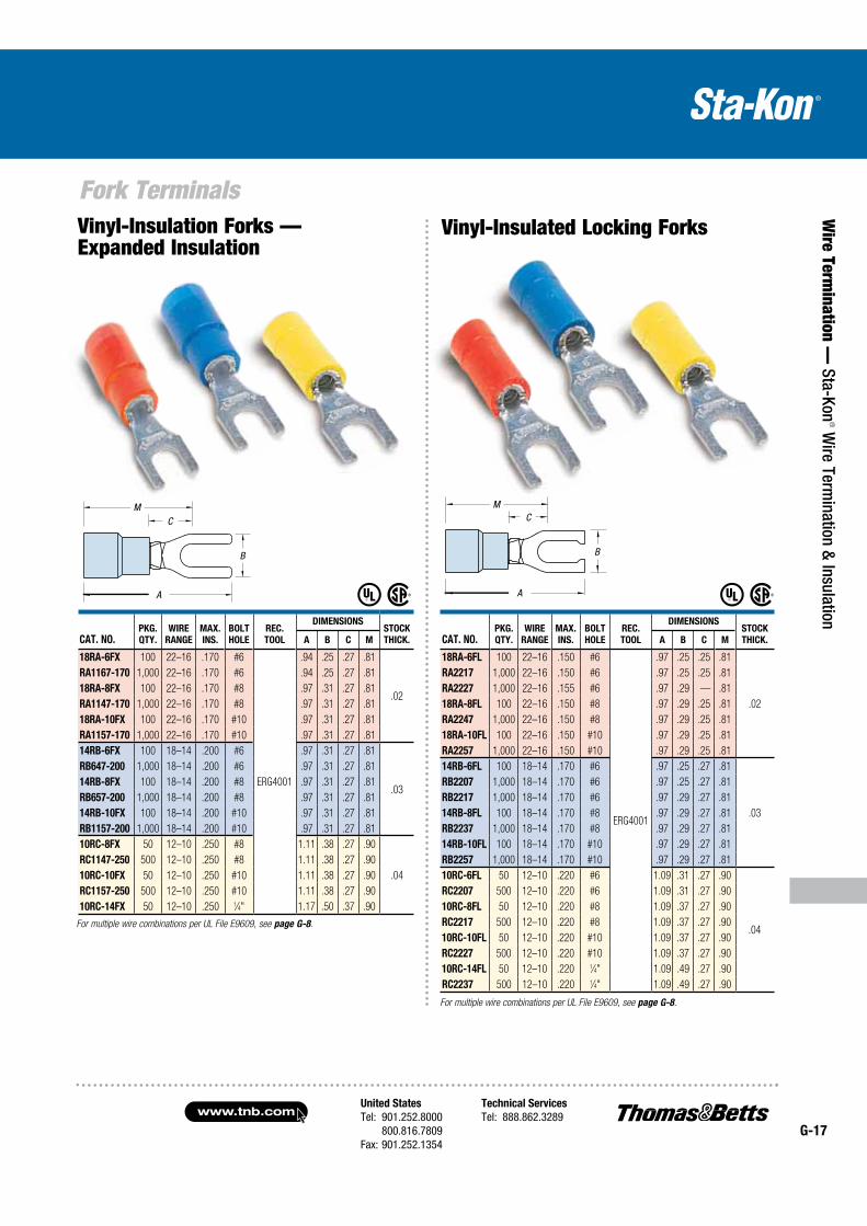
Fork Terminals
Wir
e Te
rmin
atio
n —
Sta
-Kon
® W
ire T
erm
inat
ion
& In
sula
tion Vinyl-Insulated Locking Forks —
Expanded Insulation Non-Insulated Forks
CAT. NO.PKG.
QTY.
WIRE
RANGE
BOLT
HOLE
REC.
TOOL
DIMENSIONSSTOCK
THICK.A B C M
A18-6F 100 22–16 #6
ERG4002
.72 .25 .27 .59
.02
A116 1,000 22–16 #6 .72 .25 .27 .59
A18-8F 100 22–16 #8 .75 .31 .27 .59
A114 1,000 22–16 #8 .75 .31 .27 .59
A18-10F 100 22–16 #10 .75 .31 .27 .59
A115-TB 1,000 22–16 #10 .75 .31 .27 .59
B14-6F 100 18–14 #6
ERG4002
ERG4005
.75 .31 .27 .59
.03
B64 1,000 18–14 #6 .75 .31 .27 .59
B19 1,000 18–14 #6 .66 .25 .13 .50
B14-8F 100 18–14 #8 .75 .31 .27 .59
B65-TB 1,000 18–14 #8 .75 .31 .27 .59
B14-10F 100 18–14 #10 .75 .31 .27 .59
B115 1,000 18–14 #10 .75 .31 .27 .59
B14-14F 100 18–14 1⁄4" .90 .44 .38 .68
C10-6F 50 12–10 #6 .77 .31 .27 .63
.04
C133 500 12–10 #6 .77 .31 .27 .63
C10-8F 50 12–10 #8 .82 .38 .27 .63
C114 500 12–10 #8 .82 .38 .27 .63
C10-10F 50 12–10 #10 .82 .38 .27 .63
C115 500 12–10 #10 .82 .38 .27 .63
C10-14F 50 12–10 1⁄4" .98 .50 .37 .73
C116-TB 500 12–10 1⁄4" .98 .50 .37 .73
CAT. NO.PKG.
QTY.
WIRE
RANGE
MAX.
INS.
BOLT
HOLE
REC.
TOOL
DIMENSIONSSTOCK
THICK.A B C M
18RA-6FLX 100 22–16 .170 #6
ERG4001
.97 .25 .25 .81
.02
RA2217-170 1,000 22–16 .170 #6 .97 .25 .25 .81
18RA-8FLX 100 22–16 .170 #8 .97 .29 .25 .81
18RA-10FLX 100 22–16 .170 #10 .97 .29 .25 .81
RA2257-170 1,000 22–16 .170 #10 .97 .29 .25 .81
14RB-6FLX 100 18–14 .200 #6 .97 .31 .27 .81
.03
RB2207-200 1,000 18–14 .200 #6 .97 .31 .27 .81
RB2217-200 1,000 18–14 .200 #6 .97 .29 .27 .81
14RB-8FLX 100 18–14 .200 #8 .97 .31 .27 .81
RB2237-200 1,000 18–14 .200 #8 .97 .31 .27 .81
14RB-10FLX 100 18–14 .200 #10 .97 .31 .27 .81
RB2257-200 1,000 18–14 .200 #10 .97 .31 .27 .81
10RC-6FLX 50 12–10 .250 #6 1.07 .31 .27 .91
.04
RC2207-250 500 12–10 .250 #6 1.07 .31 .27 .91
10RC-8FLX 50 12–10 .250 #8 1.10 .37 .27 .91
10RC-10FLX 50 12–10 .250 #10 1.10 .37 .27 .91
RC2227-250 500 12–10 .250 #10 1.10 .37 .27 .91
10RC-14FLX 50 12–10 .250 1⁄4" 1.22 .50 .32 .96
For multiple wire combinations per UL File E9609, see page G-8.
B
A
CM
B
A
CM
United States
Tel: 901.252.8000 800.816.7809Fax: 901.252.1354
Technical Services
Tel: 888.862.3289www.tnb.com
G-19
Fork Terminals and Pin Terminals
Wire Term
ination — Sta-Kon
® Wire Term
ination & Insulation
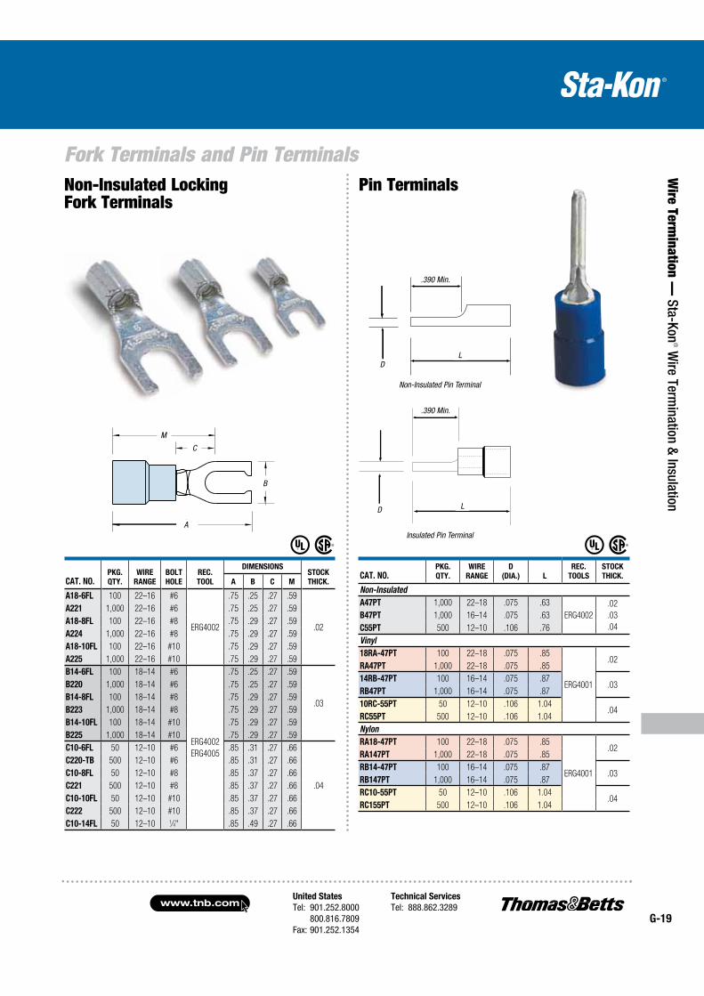
Non-Insulated Locking Fork Terminals
Pin Terminals
CAT. NO.PKG.
QTY.
WIRE
RANGE
BOLT
HOLE
REC.
TOOL
DIMENSIONSSTOCK
THICK.A B C M
A18-6FL 100 22–16 #6
ERG4002
.75 .25 .27 .59
.02
A221 1,000 22–16 #6 .75 .25 .27 .59
A18-8FL 100 22–16 #8 .75 .29 .27 .59
A224 1,000 22–16 #8 .75 .29 .27 .59
A18-10FL 100 22–16 #10 .75 .29 .27 .59
A225 1,000 22–16 #10 .75 .29 .27 .59
B14-6FL 100 18–14 #6
ERG4002
ERG4005
.75 .25 .27 .59
.03
B220 1,000 18–14 #6 .75 .25 .27 .59
B14-8FL 100 18–14 #8 .75 .29 .27 .59
B223 1,000 18–14 #8 .75 .29 .27 .59
B14-10FL 100 18–14 #10 .75 .29 .27 .59
B225 1,000 18–14 #10 .75 .29 .27 .59
C10-6FL 50 12–10 #6 .85 .31 .27 .66
.04
C220-TB 500 12–10 #6 .85 .31 .27 .66
C10-8FL 50 12–10 #8 .85 .37 .27 .66
C221 500 12–10 #8 .85 .37 .27 .66
C10-10FL 50 12–10 #10 .85 .37 .27 .66
C222 500 12–10 #10 .85 .37 .27 .66
C10-14FL 50 12–10 1⁄4" .85 .49 .27 .66
CAT. NO.PKG.
QTY.
WIRE
RANGE
D
(DIA.) L
REC.
TOOLS
STOCK
THICK.
Non-Insulated
A47PT 1,000 22–18 .075 .63
ERG4002
.02
.03
.04
B47PT 1,000 16–14 .075 .63
C55PT 500 12–10 .106 .76
Vinyl
18RA-47PT 100 22–18 .075 .85
ERG4001
.02RA47PT 1,000 22–18 .075 .85
14RB-47PT 100 16–14 .075 .87.03
RB47PT 1,000 16–14 .075 .87
10RC-55PT 50 12–10 .106 1.04.04
RC55PT 500 12–10 .106 1.04
Nylon
RA18-47PT 100 22–18 .075 .85
ERG4001
.02RA147PT 1,000 22–18 .075 .85
RB14-47PT 100 16–14 .075 .87.03
RB147PT 1,000 16–14 .075 .87
RC10-55PT 50 12–10 .106 1.04.04
RC155PT 500 12–10 .106 1.04
Insulated Pin Terminal
Non-Insulated Pin Terminal
B
A
C
M
D
D
L
L
.390 Min.
.390 Min.
www.tnb.comUnited States
Tel: 901.252.8000 800.816.7809Fax: 901.252.1354
Technical Services
Tel: 888.862.3289G-20
Splice Connectors
Wir
e Te
rmin
atio
n —
Sta
-Kon
® W
ire T
erm
inat
ion
& In
sula
tion
CAT. NO.PKG.
QTY.
MAX.
INS.
DIA.
WIRE
RANGE
REC.
TOOL
DIMENSIONS
A B
2RA18 100 .115 22–18
ERG4001
1.19 .18
RAA21 1,000 .115 22–18 1.19 .18
2RB14 100 .148 16–14 1.19 .21
RBB21 1,000 .148 16–14 1.19 .21
2RC10 50 .210 12–10 1.26 .28
RCC21 500 .210 12–10 1.26 .28
2RD8 25 .340 8
ERG4007
TBM6S
1.69 .36
RDD27 200 .340 8 1.69 .36
2RE6 20 .420 6 1.85 .45
REE28 200 .420 6 1.85 .45
2RF4 15 .510 4 TBM6S 1.85 .52
CAT. NO.PKG.
QTY.
WIRE
RANGE
REC.
TOOL
DIMENSIONS
A B
2RZZ 50 26–22ERG4006
1.22 .15
RZZ23 500 26–22 1.22 .15
2RAA 50 22–18
ERG4001
1.52 .25
RAA23 500 22–18 1.52 .25
2RBB 50 16–14 1.52 .28
RBB23 500 16–14 1.52 .28
2RCC 25 12–10 1.54 .35
RCC23 250 12–10 1.54 .35
CAT. NO.PKG.
QTY.
WIRE
RANGE
MAX.
INS.
DIA.
REC.
TOOL
DIMENSIONS
A B
RAAT21 1,000 22–18 1.22
WT145C
1.22 .115
RBBT21 1,000 16–14 1.22 1.22 .148
RCCT21 1,000 12–10 1.22 1.22 .210
Tefzel ® is a registered trademark of DuPont.
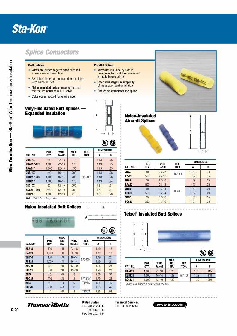
Nylon-Insulated Aircraft Splices
Tefzel® Insulated Butt Splices
Nylon-Insulated Butt Splices
Butt Splices
Wires are butted together and crimped at each end of the splice
Available either non-insulated or insulated with nylon or PVC
Nylon insulated splices meet or exceed the requirements of MIL-T-7928
Color coded according to wire size
Parallel Splices
Wires are laid side by side in the connector, and the connection is made in one crimp
Offer advantages in simplicity of installation and small size
One crimp completes the splice
CAT. NO.PKG.
QTY.
WIRE
RANGE
MAX.
INS.
REC.
TOOL
DIMENSIONS
A B
2RA18X 100 22–18 .170
ERG4001
1.13 .25
RAA217-170 1,000 22–18 .170 1.13 .25
RAA217 1,000 22–18 .150 1.13 .23
2RB14X 100 16–14 .200 1.13 .26
RBB217-200 1,000 16–14 .200 1.13 .26
RBB217 1,000 16–14 .170 1.13 .24
2RC10X 50 12–10 .250 1.31 .31
RCC217-250 500 12–10 .250 1.31 .31
RCC217 1,000 12–10 .210 1.31 .28
Note: RCC217 is not expanded.
Vinyl-Insulated Butt Splices — Expanded Insulation
A
B
A
BA
B
A
B
United States
Tel: 901.252.8000 800.816.7809Fax: 901.252.1354
Technical Services
Tel: 888.862.3289www.tnb.com
G-21
Splice Connectors
Wire Term
ination — Sta-Kon
® Wire Term
ination & Insulation
Sta-Kon® Parallel Splices
CAT. NO.PKG.
QTY.
WIRE
RANGE
REC.
TOOL
DIMENSIONS
A B
2A20 100 22–20
ERG4001
.84 .20
RAA24 1,000 22–20 .84 .20
2B-16 100 18–16 .84 .23
RBB25 1,000 18–16 .84 .23
2C-12 50 14–12 .90 .28
RCC26 500 14–12 .90 .28
CAT. NO.PKG.
QTY.
WIRE
RANGE
REC.
TOOL
DIMENSIONS
A B
2A-18 100 22–18ERG4002
.62 .12
AA2 1,000 22–18 .62 .12
2B-14 100 16–14
ERG4002
ERG4005
.62 .16
BB2 1,000 16–14 .62 .16
2C-10 50 12–10 .72 .22
CC2 500 12–10 .72 .22
2D-8 25 9–8–7
ERG4005
TBM6S
1.03 .28
DD102 200 9–8–7 1.03 .28
2E-6 20 6–5 1.12 .37
EE2 200 6–5 1.12 .37
2F-4 15 4–3
TBM6S
1.25 .44
FF2 200 4–3 1.25 .44
2G21 5 2–1 1.72 .55
GG2 25 2–1 1.72 .55
Non-Insulated Butt Splices
A
BC
CAT. NO.WIRE
RANGE
CIR. MIL
RANGE
REC.
TOOL
LENGTH
(A)
O.D.
(B)
I.D.
(C)
PKG.
QTY.
A18-PS-M 22–16 AWG 509–3,260 ERG4002 .314 .129 .086 1,000
B14-PS-M 16–14 AWG 2,050–5,180 ERG4002
ERG4005
.315 .155 .113 1,000
C10-PS-D 12–10 AWG 5,180–13,100 .380 .220 .170 500
D8-PS-D 8 AWG 13,100–20,800 ERG4005 .375 .260 .180 500
E6-PS-D 6 AWG 20,800–33,100 WT115A .500 .365 .266 500
F4-PS-W 4 AWG 33,100–52,600WT115A
.531 .410 .302 250
G2-PS-W 2 AWG 52,600–83,700 .640 .521 .396 250
H1/0-PS-C 1/0 AWG 83,700–119,500
TBM8-750M-1
.750 .571 .446 100
J2/0-PS-C 2/0 AWG 119,500–150,500 .750 .632 .507 100
K3/0-PS-L 3/0 AWG 150,500–190,000 .750 .701 .564 50
L4/0-PS-L 4/0 AWG 190,000–231,100 .770 .766 .629 50
M250-PS-Q 250 kcmil 231,100–300,000 1.063 .926 .749 25
N300-PS-X 300 kcmil 300,000–380,000 1.125 1.100 .882 10
P400-PS-X 400 kcmil 380,000–478,000 1.250 1.200 .956 10
R500-PS-V 500 kcmil 478,000–600,000 1.438 1.330 1.060 5
The total combined cross sectional area of all wires must be within the CMA range. Rated at 150° C.
Nylon-Insulated Parallel Splices
A
B
A
BC
www.tnb.comUnited States
Tel: 901.252.8000 800.816.7809Fax: 901.252.1354
Technical Services
Tel: 888.862.3289G-22
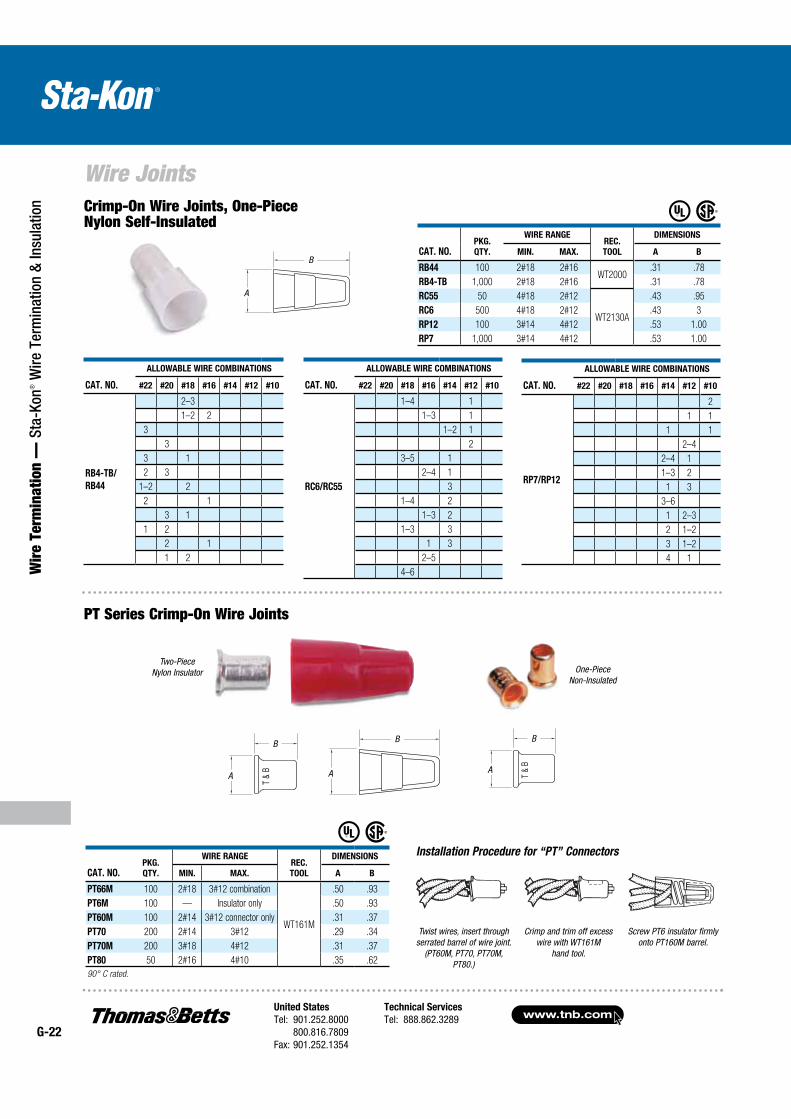
Wire Joints
Wir
e Te
rmin
atio
n —
Sta
-Kon
® W
ire T
erm
inat
ion
& In
sula
tion
Twist wires, insert through serrated barrel of wire joint.
(PT60M, PT70, PT70M, PT80.)
Crimp and trim off excess wire with WT161M
hand tool.
Screw PT6 insulator firmly onto PT160M barrel.
B
A
T&
B
B
A
T&
B
B
A
PT Series Crimp-On Wire Joints
Installation Procedure for “PT” Connectors
CAT. NO.PKG.
QTY.
WIRE RANGEREC.
TOOL
DIMENSIONS
MIN. MAX. A B
PT66M 100 2#18 3#12 combination
WT161M
.50 .93
PT6M 100 — Insulator only .50 .93
PT60M 100 2#14 3#12 connector only .31 .37
PT70 200 2#14 3#12 .29 .34
PT70M 200 3#18 4#12 .31 .37
PT80 50 2#16 4#10 .35 .62
90° C rated.
B
A
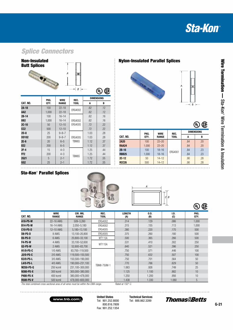
One-PieceNon-Insulated
Two-PieceNylon Insulator
Crimp-On Wire Joints, One-Piece Nylon Self-Insulated
CAT. NO.PKG.
QTY.
WIRE RANGEREC.
TOOL
DIMENSIONS
MIN. MAX. A B
RB44 100 2#18 2#16WT2000
.31 .78
RB4-TB 1,000 2#18 2#16 .31 .78
RC55 50 4#18 2#12
WT2130A
.43 .95
RC6 500 4#18 2#12 .43 3
RP12 100 3#14 4#12 .53 1.00
RP7 1,000 3#14 4#12 .53 1.00
CAT. NO.
ALLOWABLE WIRE COMBINATIONS
#22 #20 #18 #16 #14 #12 #10
RP7/RP12
2
1 1
1 1
2–4
2–4 1
1–3 2
1 3
3–6
1 2–3
2 1–2
3 1–2
4 1
CAT. NO.
ALLOWABLE WIRE COMBINATIONS
#22 #20 #18 #16 #14 #12 #10
RC6/RC55
1–4 1
1–3 1
1–2 1
2
3–5 1
2–4 1
3
1–4 2
1–3 2
1–3 3
1 3
2–5
4–6
CAT. NO.
ALLOWABLE WIRE COMBINATIONS
#22 #20 #18 #16 #14 #12 #10
RB4-TB/
RB44
2–3
1–2 2
3
3
3 1
2 3
1–2 2
2 1
3 1
1 2
2 1
1 2
A
B
A
B
A
B
A
B
United States
Tel: 901.252.8000 800.816.7809Fax: 901.252.1354
Technical Services
Tel: 888.862.3289www.tnb.com
G-23
Wire Joints
Wire Term
ination — Sta-Kon
® Wire Term
ination & Insulation
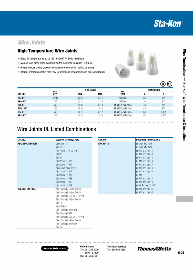
High-Temperature Wire Joints Rated for temperatures up to 150° C (302° F), 600V maximum
Molded, one-piece nylon construction for electrical insulation, UL94-V2
Brazed copper sleeve prevents separation of connection during crimping
Internal serrations enable cold flow for increased conductivity and pull-out strength
CAT. NO.PKG.
QTY.
WIRE RANGEREC.
TOOL
DIMENSIONS
MIN. MAX. A B
RB4-HT 1,000 2#18 2#16 WT2000 .36" .82"
RB44-HT 100 2#18 2#16 WT2000 .36" .82"
RC6-HT 500 3#16 3#14 ERG4001, WT2130A .48" .95"
RC551-HT 100 3#16 3#14 ERG4001, WT2130A .48” .95”
RP7-HT 500 3#14 3#12 ERG4007, WT2130A .53" 1.00"
RP12-HT 100 3#14 3#12 ERG4007, WT2130A .53" 1.00"
Wire Joints UL Listed Combinations
CAT. NO. SOLID OR STRANDED AWG
RB4, RB44, RB4-10M (2) or (3) #18
(2) #16
(1) #16 and (1) or (2) #18
(3) #22
(3) #20
(3) #22 and (1) #18
(2) #22 and (3) #20
(1) or (2) #22 and (2) #18
(2) #22 and (1) #16
(3) #20 and (1) #18
(2) #20 and (1) #22
(2) #20 and (1) #16
(1) #20 and (2) #18
RC6, RC6-5M, RC55 (1) #14 with (2), (3) or (4) #16
(1) #14 with (3), (4) or (5) #18
(2) #14 with (1), (2), (3) or (4) #18
(2) #14 with (1), (2) or (3) #16
(3) #14
(4) to (7) #18
(3) #14 with (1) or (2) #18
(3) #14 with (1) #16
(1) #12 with (1), (2), (3) or (4) #18
(1) #12 with (1), (2) or (3) #16
(1) #12 with (1) or (2) #14
(5) #16
CAT. NO. SOLID OR STRANDED AWG
RP7, RP-12 (2) to (4) #12 AWG
(3) to (6) #14 AWG
(3) #12 and (1) #14
(2) #12 and (1) #14
(2) #12 and (2) #14
(2) #12 and (3) #14
(1) #12 and (2) #14
(1) #12 and (3) #14
(1) #12 and (4) #14
(2) #10
(1) #10 and (1) #12
(1) #10 and (1) #14
(1) #8 Str. and (1) #16
(1) #10 and (1) #16
(1) #12 and (1) #16
www.tnb.comUnited States
Tel: 901.252.8000 800.816.7809Fax: 901.252.1354
Technical Services
Tel: 888.862.3289G-24
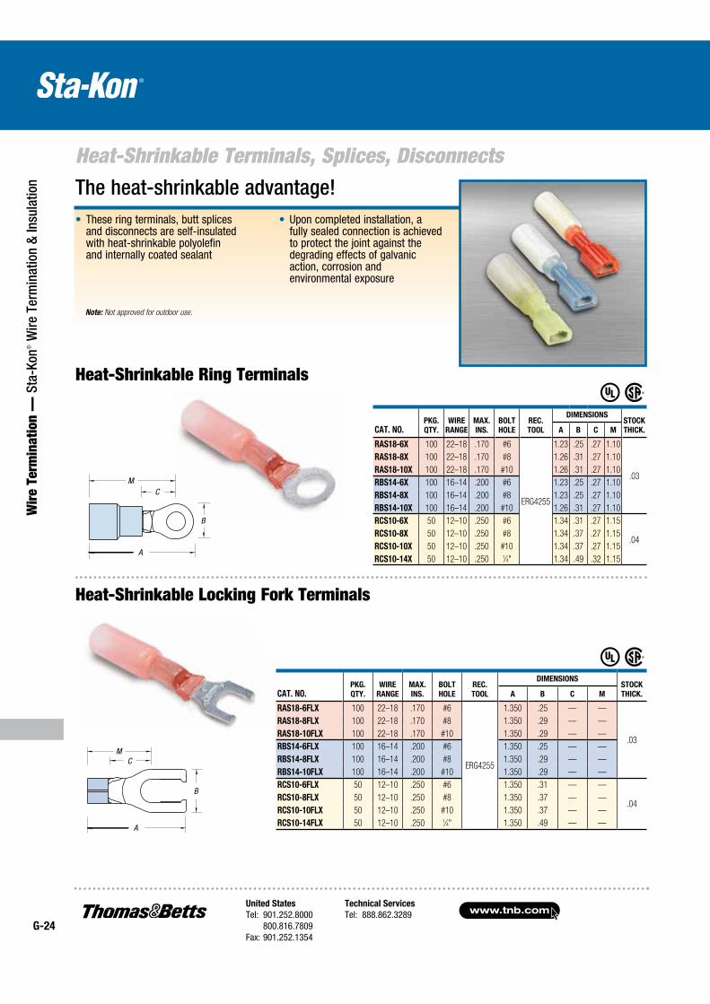
Heat-Shrinkable Terminals, Splices, Disconnects
Wir
e Te
rmin
atio
n —
Sta
-Kon
® W
ire T
erm
inat
ion
& In
sula
tion
Heat-Shrinkable Locking Fork Terminals
CAT. NO.PKG.
QTY.
WIRE
RANGE
MAX.
INS.
BOLT
HOLE
REC.
TOOL
DIMENSIONSSTOCK
THICK.A B C M
RAS18-6FLX 100 22–18 .170 #6
ERG4255
1.350 .25 — —
.03
RAS18-8FLX 100 22–18 .170 #8 1.350 .29 — —
RAS18-10FLX 100 22–18 .170 #10 1.350 .29 — —
RBS14-6FLX 100 16–14 .200 #6 1.350 .25 — —
RBS14-8FLX 100 16–14 .200 #8 1.350 .29 — —
RBS14-10FLX 100 16–14 .200 #10 1.350 .29 — —
RCS10-6FLX 50 12–10 .250 #6 1.350 .31 — —
.04RCS10-8FLX 50 12–10 .250 #8 1.350 .37 — —
RCS10-10FLX 50 12–10 .250 #10 1.350 .37 — —
RCS10-14FLX 50 12–10 .250 1⁄4" 1.350 .49 — —
The heat-shrinkable advantage! These ring terminals, butt splices and disconnects are self-insulated with heat-shrinkable polyolefin and internally coated sealant
Upon completed installation, a fully sealed connection is achieved to protect the joint against the degrading effects of galvanic action, corrosion and environmental exposure
CAT. NO.PKG.
QTY.
WIRE
RANGE
MAX.
INS.
BOLT
HOLE
REC.
TOOL
DIMENSIONSSTOCK
THICK.A B C M
RAS18-6X 100 22–18 .170 #6
ERG4255
1.23 .25 .27 1.10
.03
RAS18-8X 100 22–18 .170 #8 1.26 .31 .27 1.10
RAS18-10X 100 22–18 .170 #10 1.26 .31 .27 1.10
RBS14-6X 100 16–14 .200 #6 1.23 .25 .27 1.10
RBS14-8X 100 16–14 .200 #8 1.23 .25 .27 1.10
RBS14-10X 100 16–14 .200 #10 1.26 .31 .27 1.10
RCS10-6X 50 12–10 .250 #6 1.34 .31 .27 1.15
.04RCS10-8X 50 12–10 .250 #8 1.34 .37 .27 1.15
RCS10-10X 50 12–10 .250 #10 1.34 .37 .27 1.15
RCS10-14X 50 12–10 .250 1⁄4" 1.34 .49 .32 1.15
M
Heat-Shrinkable Ring Terminals
Note: Not approved for outdoor use.
A
B
CM
A
B
CM
United States
Tel: 901.252.8000 800.816.7809Fax: 901.252.1354
Technical Services
Tel: 888.862.3289www.tnb.com
G-25
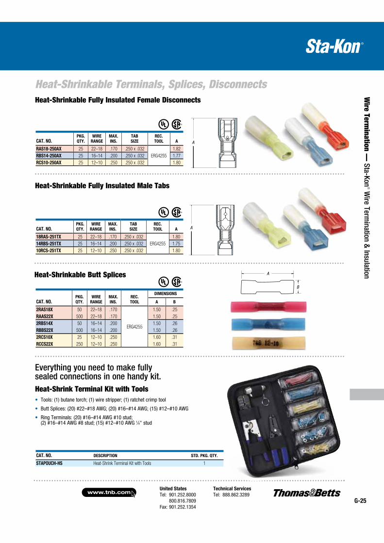
Heat-Shrinkable Terminals, Splices, Disconnects
Wire Term
ination — Sta-Kon
® Wire Term
ination & Insulation
Heat-Shrinkable Fully Insulated Female Disconnects
CAT. NO.PKG.
QTY.
WIRE
RANGE
MAX.
INS.
TAB
SIZE
REC.
TOOL A
18RAS-251TX 25 22–18 .170 .250 x .032
ERG4255
1.80
14RBS-251TX 25 16–14 .200 .250 x .032 1.75
10RCS-251TX 25 12–10 .250 .250 x .032 1.80
Heat-Shrinkable Fully Insulated Male Tabs
CAT. NO.PKG.
QTY.
WIRE
RANGE
MAX.
INS.
REC.
TOOL
DIMENSIONS
A B
2RAS18X 50 22–18 .170
ERG4255
1.50 .25
RAAS22X 500 22–18 .170 1.50 .25
2RBS14X 50 16–14 .200 1.50 .26
RBBS22X 500 16–14 .200 1.50 .26
2RCS10X 25 12–10 .250 1.60 .31
RCCS22X 250 12–10 .250 1.60 .31
Heat-Shrinkable Butt SplicesB
A
Everything you need to make fully sealed connections in one handy kit.Heat-Shrink Terminal Kit with Tools
Tools: (1) butane torch; (1) wire stripper; (1) ratchet crimp tool
Butt Splices: (20) #22–#18 AWG; (20) #16–#14 AWG; (15) #12–#10 AWG
Ring Terminals: (20) #16–#14 AWG #10 stud; (2) #16–#14 AWG #8 stud; (15) #12–#10 AWG 1⁄4" stud
CAT. NO.PKG.
QTY.
WIRE
RANGE
MAX.
INS.
TAB
SIZE
REC.
TOOL A
RAS18-250AX 25 22–18 .170 .250 x .032
ERG4255
1.82
RBS14-250AX 25 16–14 .200 .250 x .032 1.77
RCS10-250AX 25 12–10 .250 .250 x .032 1.80
CAT. NO. DESCRIPTION STD. PKG. QTY.
STAPOUCH-HS Heat-Shrink Terminal Kit with Tools 1
A
A
A
B
A
A
www.tnb.comUnited States
Tel: 901.252.8000 800.816.7809Fax: 901.252.1354
Technical Services
Tel: 888.862.3289G-26
Disconnects and Male Tabs
Wir
e Te
rmin
atio
n —
Sta
-Kon
® W
ire T
erm
inat
ion
& In
sula
tion
A
B
Nylon self-insulated1
Vinyl self-insulated
Nylon fully insulated
Non-insulated
Nylon open top insulated 90° flag
2
3
4
5
6
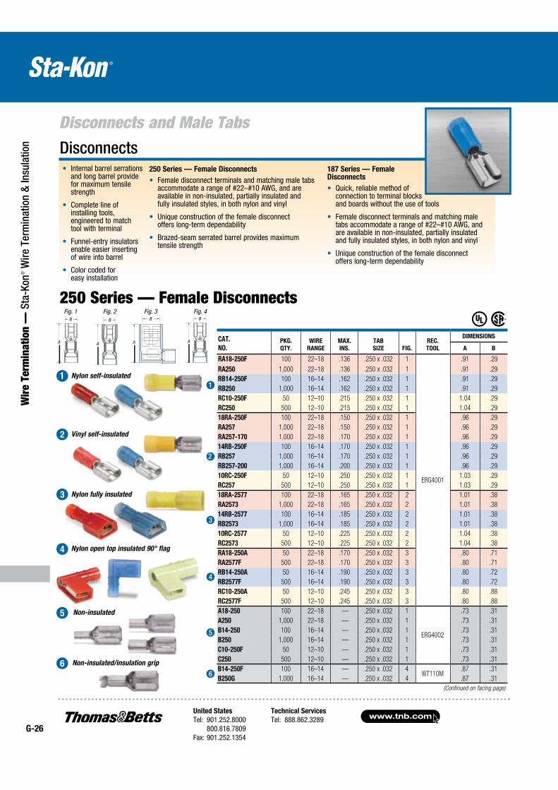
Disconnects250 Series — Female Disconnects
Female disconnect terminals and matching male tabs accommodate a range of #22–#10 AWG, and are available in non-insulated, partially insulated and fully insulated styles, in both nylon and vinyl
Unique construction of the female disconnect offers long-term dependability
Brazed-seam serrated barrel provides maximum tensile strength
187 Series — Female Disconnects
Quick, reliable method of connection to terminal blocks and boards without the use of tools
Female disconnect terminals and matching male tabs accommodate a range of #22–#10 AWG, and are available in non-insulated, partially insulated and fully insulated styles, in both nylon and vinyl
Unique construction of the female disconnect offers long-term dependability
Internal barrel serrations and long barrel provide for maximum tensile strength
Complete line of installing tools, engineered to match tool with terminal
Funnel-entry insulators enable easier inserting of wire into barrel
Color coded for easy installation
Fig. 1 Fig. 3
A
B
Fig. 2B
A
Non-insulated/insulation grip
Fig. 4
(Continued on facing page)
250 Series — Female Disconnects
CAT.
NO.PKG.
QTY.
WIRE
RANGE
MAX.
INS.
TAB
SIZE FIG.
REC.
TOOL
DIMENSIONS
A B
RA18-250F 100 22–18 .136 .250 x .032 1
ERG4001
.91 .29
RA250 1,000 22–18 .136 .250 x .032 1 .91 .29
RB14-250F 100 16–14 .162 .250 x .032 1 .91 .29
RB250 1,000 16–14 .162 .250 x .032 1 .91 .29
RC10-250F 50 12–10 .215 .250 x .032 1 1.04 .29
RC250 500 12–10 .215 .250 x .032 1 1.04 .29
18RA-250F 100 22–18 .150 .250 x .032 1 .96 .29
RA257 1,000 22–18 .150 .250 x .032 1 .96 .29
RA257-170 1,000 22–18 .170 .250 x .032 1 .96 .29
14RB-250F 100 16–14 .170 .250 x .032 1 .96 .29
RB257 1,000 16–14 .170 .250 x .032 1 .96 .29
RB257-200 1,000 16–14 .200 .250 x .032 1 .96 .29
10RC-250F 50 12–10 .250 .250 x .032 1 1.03 .29
RC257 500 12–10 .250 .250 x .032 1 1.03 .29
18RA-2577 100 22–18 .165 .250 x .032 2 1.01 .38
RA2573 1,000 22–18 .165 .250 x .032 2 1.01 .38
14RB-2577 100 16–14 .185 .250 x .032 2 1.01 .38
RB2573 1,000 16–14 .185 .250 x .032 2 1.01 .38
10RC-2577 50 12–10 .225 .250 x .032 2 1.04 .38
RC2573 500 12–10 .225 .250 x .032 2 1.04 .38
RA18-250A 50 22–18 .170 .250 x .032 3 .80 .71
RA2577F 500 22–18 .170 .250 x .032 3 .80 .71
RB14-250A 50 16–14 .190 .250 x .032 3 .80 .72
RB2577F 500 16–14 .190 .250 x .032 3 .80 .72
RC10-250A 50 12–10 .245 .250 x .032 3 .80 .88
RC2577F 500 12–10 .245 .250 x .032 3 .80 .88
A18-250 100 22–18 — .250 x .032 1
ERG4002
.73 .31
A250 1,000 22–18 — .250 x .032 1 .73 .31
B14-250 100 16–14 — .250 x .032 1 .73 .31
B250 1,000 16–14 — .250 x .032 1 .73 .31
C10-250F 50 12–10 — .250 x .032 1 .73 .31
C250 500 12–10 — .250 x .032 1 .73 .31
B14-250F 100 16–14 — .250 x .032 4WT110M
.87 .31
B250G 1,000 16–14 — .250 x .032 4 .87 .31
1
2
3
4
5
6
A A A A
BBBB
United States
Tel: 901.252.8000 800.816.7809Fax: 901.252.1354
Technical Services
Tel: 888.862.3289www.tnb.com
G-27
Disconnects and Male Tabs
Wire Term
ination — Sta-Kon
® Wire Term
ination & Insulation
B
C
30O
A
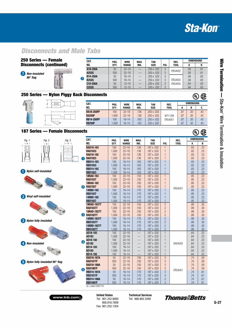
250 Series — Female Disconnects (continued)
250 Series — Nylon Piggy Back Disconnects
187 Series — Female Disconnects
Non-insulated
90° flag
Nylon self-insulated1
Vinyl self-insulated
Nylon fully insulated
Non-insulated
Nylon fully insulated 90° flag
2
3
4
5
7
CAT.
NO.PKG.
QTY.
WIRE
RANGE
MAX.
INS.
TAB
SIZE FIG.
REC.
TOOL
DIMENSIONS
A B
RAD18-183 100 22–18 .136 .187 x .032 1
ERG4001
.83 .23
RAD1833 1,000 22–18 .136 .187 x .032 1 .83 .23
RAD18-182 100 22–18 .136 .187 x .020 1 .83 .23
RAD1823 1,000 22–18 .136 .187 x .020 1 .83 .23
RBD14-183 100 16–14 .163 .187 x .032 1 .83 .23
RBD1833 1,000 16–14 .163 .187 x .032 1 .83 .23
RBD14-182 100 16–14 .163 .187 x .020 1 .83 .23
RBD1823 1,000 16–14 .163 .187 x .020 1 .83 .23
18RAD-183 100 22–18 .150 .187 x .032 1 .85 .23
RAD1837 1,000 22–18 .150 .187 x .032 1 .85 .23
18RAD-182 100 22–18 .150 .187 x .020 1 .85 .23
RAD1827 1,000 22–18 .150 .187 x .020 1 .85 .23
14RBD-183 100 16–14 .170 .187 x .032 1 .85 .23
RBD1837 1,000 16–14 .170 .187 x .032 1 .85 .23
14RBD-182 100 16–14 .170 .187 x .020 1 .85 .23
RBD1827 1,000 16–14 .170 .187 x .020 1 .85 .23
18RAD-18377 100 22–18 .150 .187 x .032 2 .89 .30
RAD18377 1,000 22–18 .150 .187 x .032 2 .89 .30
18RAD-18277 100 22–18 .150 .187 x .020 2 .89 .30
RAD18277 1,000 22–18 .150 .187 x .020 2 .89 .30
14RBD-18377 100 16–14 .170 .187 x .032 2 .89 .30
RBD18377 1,000 16–14 .170 .187 x .032 2 .89 .30
14RBD-18277 100 16–14 .170 .187 x .020 2 .89 .30
RBD18277 1,000 16–14 .170 .187 x .020 2 .89 .30
AD18-183 100 22–18 — .187 x .032 1
ERG4002
.64 .23
AD183 1,000 22–18 — .187 x .032 1 .64 .23
AD18-182 100 22–18 — .187 x .020 1 .64 .23
AD182 1,000 22–18 — .187 x .020 1 .64 .23
BD14-183 100 16–14 — .187 x .032 1 .64 .23
BD183 1,000 16–14 — .187 x .032 1 .64 .23
BD14-182 100 16–14 — .187 x .020 1 .64 .23
RAD18-187A 50 22–18 .150 .187 x .032 3
ERG4001
.74 .59
RAD1877F 500 22–18 .150 .187 x .032 3 .74 .59
RAD18-188A 50 22–18 .150 .187 x .020 3 .74 .59
RAD1887F 500 22–18 .150 .187 x .020 3 .74 .59
RBD14-187A 50 16–14 .170 .187 x .032 3 .74 .61
RBD1877F 500 16–14 .170 .187 x .032 3 .74 .61
RBD14-188A 50 16–14 .170 .187 x .020 3 .74 .61
RBD1887F 500 16–14 .170 .187 x .020 3 .74 .61UL Listed E66716
1
2
3
4
5
7
CAT.
NO.PKG.
QTY.
WIRE
RANGE
MAX.
INS.
TAB
SIZE
REC.
TOOL
DIMENSIONS
A B C
RA18-250FP 100 22–18 .136 .250 x .032
WT112M
ERG4001
.87 .30 .43
RA250P 1,000 22–18 .136 .250 x .032 .87 .30 .43
RB14-250FP 100 16–14 .163 .250 x .032 .87 .30 .43
RB250P 1,000 16–14 .163 .250 x .032 .87 .30 .43
CAT.
NO.PKG.
QTY.
WIRE
RANGE
MAX.
INS.
TAB
SIZE FIG.
REC.
TOOL
DIMENSIONS
A B
A18-250A 50 22–18 — .250 x .032 3ERG4002
.58 .61
A252G 500 22–18 — .250 x .032 3 .58 .61
B14-250A 50 16–14 — .250 x .032 3
ERG4002
ERG4005
.58 .62
B252G 500 16–14 — .250 x .032 3 .58 .62
C10-250A 50 12–10 — .250 x .032 3 .64 .63
C252G 500 12–10 — .250 x .032 3 .64 .63
Fig. 1
A
B
Fig. 3
A
B
Fig. 2B
A
B
A
C
B
A
B B
A A
30°
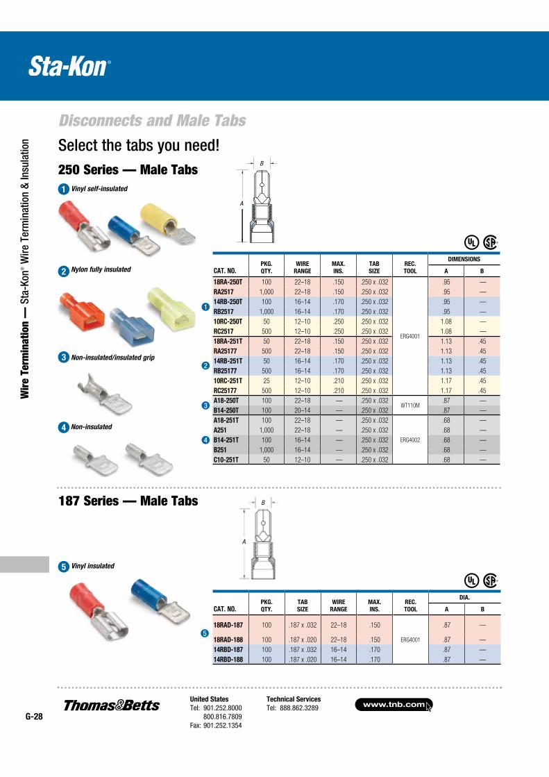
www.tnb.comUnited States
Tel: 901.252.8000 800.816.7809Fax: 901.252.1354
Technical Services
Tel: 888.862.3289G-28
Disconnects and Male Tabs
Wir
e Te
rmin
atio
n —
Sta
-Kon
® W
ire T
erm
inat
ion
& In
sula
tion Select the tabs you need!
250 Series — Male TabsVinyl self-insulated
187 Series — Male Tabs
1
Nylon fully insulated
Non-insulated/insulated grip
Vinyl insulated
Non-insulated
2
3
4
5
2
3
4
5
1
CAT. NO.PKG.
QTY.
WIRE
RANGE
MAX.
INS.
TAB
SIZE
REC.
TOOL
DIMENSIONS
A B
18RA-250T 100 22–18 .150 .250 x .032
ERG4001
.95 —
RA2517 1,000 22–18 .150 .250 x .032 .95 —
14RB-250T 100 16–14 .170 .250 x .032 .95 —
RB2517 1,000 16–14 .170 .250 x .032 .95 —
10RC-250T 50 12–10 .250 .250 x .032 1.08 —
RC2517 500 12–10 .250 .250 x .032 1.08 —
18RA-251T 50 22–18 .150 .250 x .032 1.13 .45
RA25177 500 22–18 .150 .250 x .032 1.13 .45
14RB-251T 50 16–14 .170 .250 x .032 1.13 .45
RB25177 500 16–14 .170 .250 x .032 1.13 .45
10RC-251T 25 12–10 .210 .250 x .032 1.17 .45
RC25177 500 12–10 .210 .250 x .032 1.17 .45
A18-250T 100 22–18 — .250 x .032WT110M
.87 —
B14-250T 100 20–14 — .250 x .032 .87 —
A18-251T 100 22–18 — .250 x .032
ERG4002
.68 —
A251 1,000 22–18 — .250 x .032 .68 —
B14-251T 100 16–14 — .250 x .032 .68 —
B251 1,000 16–14 — .250 x .032 .68 —
C10-251T 50 12–10 — .250 x .032 .68 —
CAT. NO.PKG.
QTY.
TAB
SIZE
WIRE
RANGE
MAX.
INS.
REC.
TOOL
DIA.
A B
18RAD-187 100 .187 x .032 22–18 .150
ERG4001
.87 —
18RAD-188 100 .187 x .020 22–18 .150 .87 —
14RBD-187 100 .187 x .032 16–14 .170 .87 —
14RBD-188 100 .187 x .020 16–14 .170 .87 —
A
B
A
B
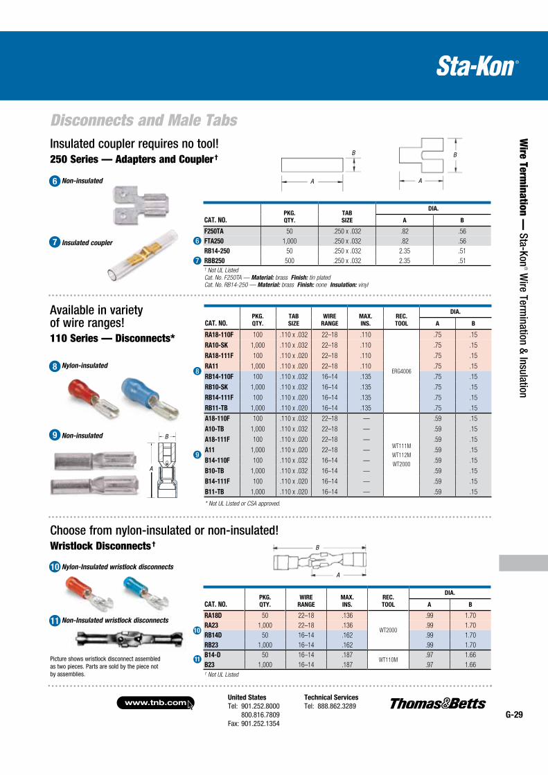
United States
Tel: 901.252.8000 800.816.7809Fax: 901.252.1354
Technical Services
Tel: 888.862.3289www.tnb.com
G-29
Disconnects and Male Tabs
Wire Term
ination — Sta-Kon
® Wire Term
ination & Insulation
Insulated coupler requires no tool!250 Series — Adapters and Coupler†
Picture shows wristlock disconnect assembled as two pieces. Parts are sold by the piece not by assemblies.
Choose from nylon-insulated or non-insulated!Wristlock Disconnects†
Non-insulated
Insulated coupler
Available in variety of wire ranges!
Nylon-insulated
110 Series — Disconnects*
Nylon-Insulated wristlock disconnects
Non-Insulated wristlock disconnects
10
11
CAT. NO.PKG.
QTY.
TAB
SIZE
WIRE
RANGE
MAX.
INS.
REC.
TOOL
DIA.
A B
RA18-110F 100 .110 x .032 22–18 .110
ERG4006
.75 .15
RA10-SK 1,000 .110 x .032 22–18 .110 .75 .15
RA18-111F 100 .110 x .020 22–18 .110 .75 .15
RA11 1,000 .110 x .020 22–18 .110 .75 .15
RB14-110F 100 .110 x .032 16–14 .135 .75 .15
RB10-SK 1,000 .110 x .032 16–14 .135 .75 .15
RB14-111F 100 .110 x .020 16–14 .135 .75 .15
RB11-TB 1,000 .110 x .020 16–14 .135 .75 .15
A18-110F 100 .110 x .032 22–18 —
WT111M
WT112M
WT2000
.59 .15
A10-TB 1,000 .110 x .032 22–18 — .59 .15
A18-111F 100 .110 x .020 22–18 — .59 .15
A11 1,000 .110 x .020 22–18 — .59 .15
B14-110F 100 .110 x .032 16–14 — .59 .15
B10-TB 1,000 .110 x .032 16–14 — .59 .15
B14-111F 100 .110 x .020 16–14 — .59 .15
B11-TB 1,000 .110 x .020 16–14 — .59 .15
* Not UL Listed or CSA approved.
CAT. NO.PKG.
QTY.
WIRE
RANGE
MAX.
INS.
REC.
TOOL
DIA.
A B
RA18D 50 22–18 .136
WT2000
.99 1.70
RA23 1,000 22–18 .136 .99 1.70
RB14D 50 16–14 .162 .99 1.70
RB23 1,000 16–14 .162 .99 1.70
B14-D 50 16–14 .187WT110M
.97 1.66
B23 1,000 16–14 .187 .97 1.66† Not UL Listed
Non-insulated
CAT. NO.PKG.
QTY.
TAB
SIZE
DIA.
A B
F250TA 50 .250 x .032 .82 .56
FTA250 1,000 .250 x .032 .82 .56
RB14-250 50 .250 x .032 2.35 .51
RBB250 500 .250 x .032 2.35 .51† Not UL Listed
Cat. No. F250TA — Material: brass Finish: tin plated
Cat. No. RB14-250 — Material: brass Finish: none Insulation: vinyl
6
7
8
9
10
11
6
7
8
9
A
B
A
B
A
B
A
B
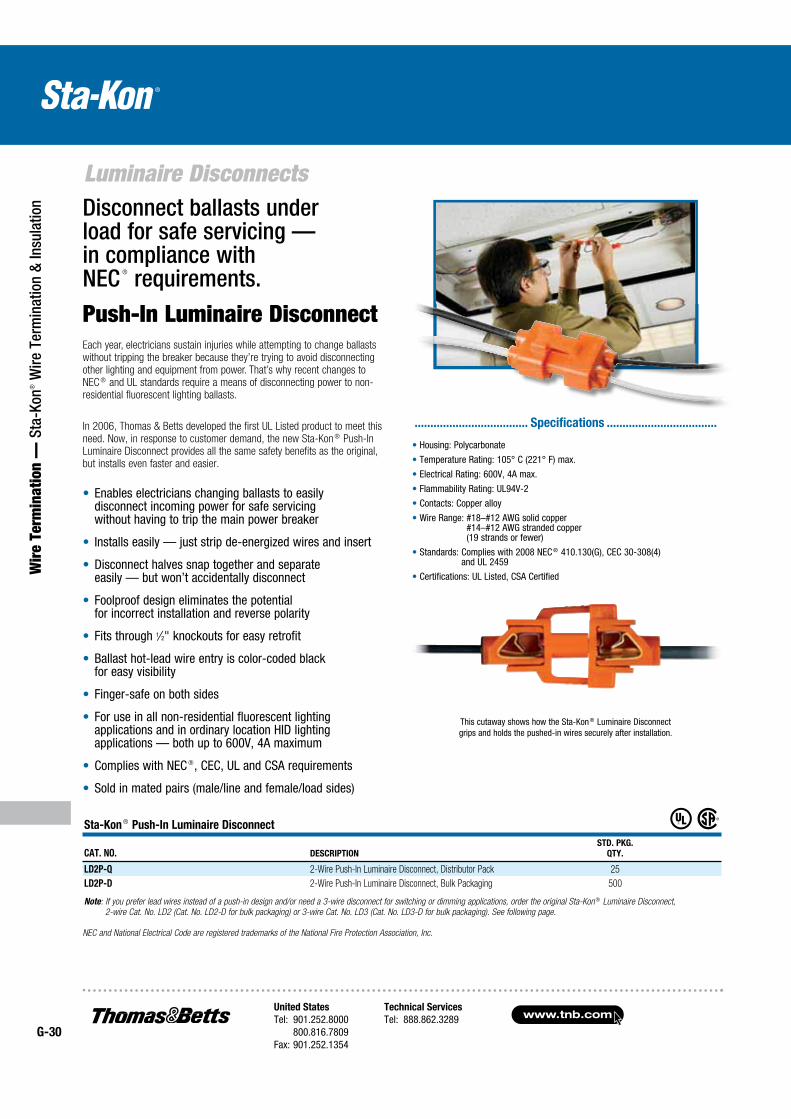
www.tnb.comUnited States
Tel: 901.252.8000 800.816.7809Fax: 901.252.1354
Technical Services
Tel: 888.862.3289G-30
Luminaire Disconnects
Wir
e Te
rmin
atio
n —
Sta
-Kon
® W
ire T
erm
inat
ion
& In
sula
tion Disconnect ballasts under
load for safe servicing — in compliance with NEC ® requirements.
Push-In Luminaire DisconnectEach year, electricians sustain injuries while attempting to change ballasts without tripping the breaker because they’re trying to avoid disconnecting other lighting and equipment from power. That’s why recent changes to NEC ® and UL standards require a means of disconnecting power to non-residential fluorescent lighting ballasts.
In 2006, Thomas & Betts developed the first UL Listed product to meet this need. Now, in response to customer demand, the new Sta-Kon ® Push-In Luminaire Disconnect provides all the same safety benefits as the original, but installs even faster and easier.
Enables electricians changing ballasts to easily disconnect incoming power for safe servicing without having to trip the main power breaker
Installs easily — just strip de-energized wires and insert
Disconnect halves snap together and separate easily — but won’t accidentally disconnect
Foolproof design eliminates the potential for incorrect installation and reverse polarity
Fits through 1⁄2" knockouts for easy retrofit
Ballast hot-lead wire entry is color-coded black for easy visibility
Finger-safe on both sides
For use in all non-residential fluorescent lighting applications and in ordinary location HID lighting applications — both up to 600V, 4A maximum
Complies with NEC ®, CEC, UL and CSA requirements
Sold in mated pairs (male/line and female/load sides)
This cutaway shows how the Sta-Kon ® Luminaire Disconnect grips and holds the pushed-in wires securely after installation.
Sta-Kon ® Push-In Luminaire Disconnect
CAT. NO. DESCRIPTION
STD. PKG.
QTY.
LD2P-Q 2-Wire Push-In Luminaire Disconnect, Distributor Pack 25
LD2P-D 2-Wire Push-In Luminaire Disconnect, Bulk Packaging 500
Note: If you prefer lead wires instead of a push-in design and/or need a 3-wire disconnect for switching or dimming applications, order the original Sta-Kon ® Luminaire Disconnect,
2-wire Cat. No. LD2 (Cat. No. LD2-D for bulk packaging) or 3-wire Cat. No. LD3 (Cat. No. LD3-D for bulk packaging). See following page.
Housing: Polycarbonate
Temperature Rating: 105° C (221° F) max.
Electrical Rating: 600V, 4A max.
Flammability Rating: UL94V-2
Contacts: Copper alloy
Wire Range: #18–#12 AWG solid copper #14–#12 AWG stranded copper (19 strands or fewer)
Standards: Complies with 2008 NEC ® 410.130(G), CEC 30-308(4) and UL 2459
Certifications: UL Listed, CSA Certified
.................................... Specifications ...................................
NEC and National Electrical Code are registered trademarks of the National Fire Protection Association, Inc.
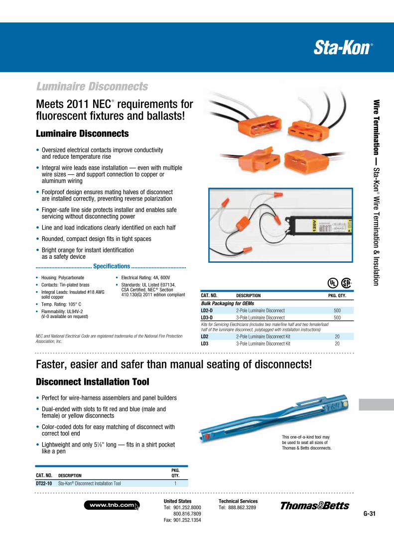
United States
Tel: 901.252.8000 800.816.7809Fax: 901.252.1354
Technical Services
Tel: 888.862.3289www.tnb.com
G-31
Luminaire Disconnects
Wire Term
ination — Sta-Kon
® Wire Term
ination & Insulation
Luminaire Disconnects
Oversized electrical contacts improve conductivity and reduce temperature rise
Integral wire leads ease installation — even with multiple wire sizes — and support connection to copper or aluminum wiring
Foolproof design ensures mating halves of disconnect are installed correctly, preventing reverse polarization
Finger-safe line side protects installer and enables safe servicing without disconnecting power
Line and load indications clearly identified on each half
Rounded, compact design fits in tight spaces
Bright orange for instant identification as a safety device
Meets 2011 NEC® requirements for fluorescent fixtures and ballasts!
Faster, easier and safer than manual seating of disconnects!Disconnect Installation Tool
This one-of-a-kind tool may be used to seat all sizes of Thomas & Betts disconnects.
CAT. NO. DESCRIPTION
PKG.
QTY.
DT22-10 Sta-Kon® Disconnect Installation Tool 1
Perfect for wire-harness assemblers and panel builders
Dual-ended with slots to fit red and blue (male and female) or yellow disconnects
Color-coded dots for easy matching of disconnect with correct tool end
Lightweight and only 51⁄8" long — fits in a shirt pocket like a pen
CAT. NO. DESCRIPTION PKG. QTY.
Bulk Packaging for OEMs
LD2-D 2-Pole Luminaire Disconnect 500
LD3-D 3-Pole Luminaire Disconnect 500
Kits for Servicing Electricians (includes two male/line half and two female/load
half of the luminaire disconnect, polybagged with installation instructions)
LD2 2-Pole Luminaire Disconnect Kit 20
LD3 3-Pole Luminaire Disconnect Kit 20
Housing: Polycarbonate
Contacts: Tin-plated brass
Integral Leads: Insulated #18 AWG solid copper
Temp. Rating: 105° C
Flammability: UL94V-2 (V-0 available on request)
Electrical Rating: 4A, 600V
Standards: UL Listed E07134, CSA Certified, NEC ® Section 410.130(G) 2011 edition compliant
.................................... Specifications ...................................
NEC and National Electrical Code are registered trademarks of the National Fire Protection
Association, Inc.
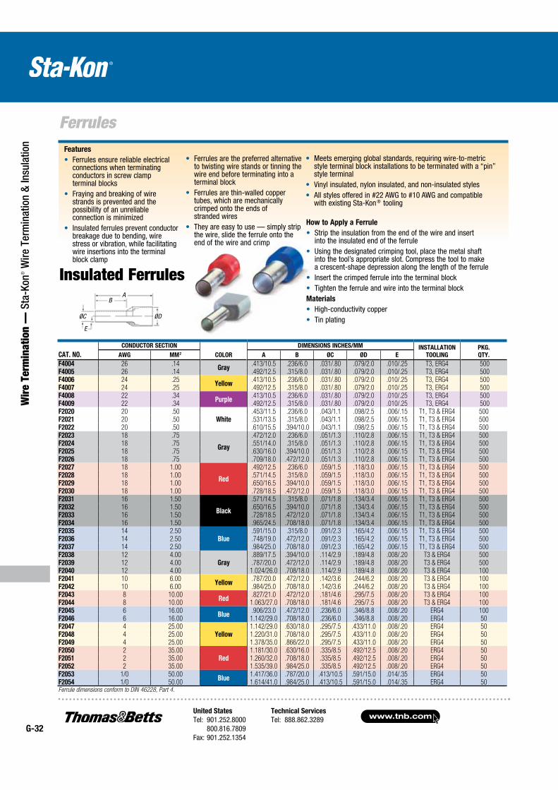
www.tnb.comUnited States
Tel: 901.252.8000 800.816.7809Fax: 901.252.1354
Technical Services
Tel: 888.862.3289G-32
Ferrules
Wir
e Te
rmin
atio
n —
Sta
-Kon
® W
ire T
erm
inat
ion
& In
sula
tion
ØC ØD
BA
E
Insulated Ferrules
Ferrules are the preferred alternative to twisting wire stands or tinning the wire end before terminating into a terminal block
Ferrules are thin-walled copper tubes, which are mechanically crimped onto the ends of stranded wires
They are easy to use — simply strip the wire, slide the ferrule onto the end of the wire and crimp
Features
Ferrules ensure reliable electrical connections when terminating conductors in screw clamp terminal blocks
Fraying and breaking of wire strands is prevented and the possibility of an unreliable connection is minimized
Insulated ferrules prevent conductor breakage due to bending, wire stress or vibration, while facilitating wire insertions into the terminal block clamp
How to Apply a Ferrule
Strip the insulation from the end of the wire and insert into the insulated end of the ferrule
Using the designated crimping tool, place the metal shaft into the tool’s appropriate slot. Compress the tool to make a crescent-shape depression along the length of the ferrule
Insert the crimped ferrule into the terminal block Tighten the ferrule and wire into the terminal block
Materials
High-conductivity copper Tin plating
Meets emerging global standards, requiring wire-to-metric style terminal block installations to be terminated with a “pin” style terminal
Vinyl insulated, nylon insulated, and non-insulated styles All styles offered in #22 AWG to #10 AWG and compatible
with existing Sta-Kon ® tooling
CAT. NO.
CONDUCTOR SECTION
COLOR
DIMENSIONS INCHES/MM INSTALLATION
TOOLING
PKG.
QTY.AWG MM2 A B ØC ØD E
F4004 26 .14Gray
.413/10.5 .236/6.0 .031/.80 .079/2.0 .010/.25 T3, ERG4 500 F4005 26 .14 .492/12.5 .315/8.0 .031/.80 .079/2.0 .010/.25 T3, ERG4 500 F4006 24 .25
Yellow.413/10.5 .236/6.0 .031/.80 .079/2.0 .010/.25 T3, ERG4 500
F4007 24 .25 .492/12.5 .315/8.0 .031/.80 .079/2.0 .010/.25 T3, ERG4 500 F4008 22 .34
Purple.413/10.5 .236/6.0 .031/.80 .079/2.0 .010/.25 T3, ERG4 500
F4009 22 .34 .492/12.5 .315/8.0 .031/.80 .079/2.0 .010/.25 T3, ERG4 500 F2020 20 .50
White.453/11.5 .236/6.0 .043/1.1 .098/2.5 .006/.15 T1, T3 & ERG4 500
F2021 20 .50 .531/13.5 .315/8.0 .043/1.1 .098/2.5 .006/.15 T1, T3 & ERG4 500F2022 20 .50 .610/15.5 .394/10.0 .043/1.1 .098/2.5 .006/.15 T1, T3 & ERG4 500F2023 18 .75
Gray
.472/12.0 .236/6.0 .051/1.3 .110/2.8 .006/.15 T1, T3 & ERG4 500F2024 18 .75 .551/14.0 .315/8.0 .051/1.3 .110/2.8 .006/.15 T1, T3 & ERG4 500F2025 18 .75 .630/16.0 .394/10.0 .051/1.3 .110/2.8 .006/.15 T1, T3 & ERG4 500F2026 18 .75 .709/18.0 .472/12.0 .051/1.3 .110/2.8 .006/.15 T1, T3 & ERG4 500F2027 18 1.00
Red
.492/12.5 .236/6.0 .059/1.5 .118/3.0 .006/.15 T1, T3 & ERG4 500F2028 18 1.00 .571/14.5 .315/8.0 .059/1.5 .118/3.0 .006/.15 T1, T3 & ERG4 500F2029 18 1.00 .650/16.5 .394/10.0 .059/1.5 .118/3.0 .006/.15 T1, T3 & ERG4 500F2030 18 1.00 .728/18.5 .472/12.0 .059/1.5 .118/3.0 .006/.15 T1, T3 & ERG4 500F2031 16 1.50
Black
.571/14.5 .315/8.0 .071/1.8 .134/3.4 .006/.15 T1, T3 & ERG4 500F2032 16 1.50 .650/16.5 .394/10.0 .071/1.8 .134/3.4 .006/.15 T1, T3 & ERG4 500F2033 16 1.50 .728/18.5 .472/12.0 .071/1.8 .134/3.4 .006/.15 T1, T3 & ERG4 500F2034 16 1.50 .965/24.5 .708/18.0 .071/1.8 .134/3.4 .006/.15 T1, T3 & ERG4 500F2035 14 2.50
Blue.591/15.0 .315/8.0 .091/2.3 .165/4.2 .006/.15 T1, T3 & ERG4 500
F2036 14 2.50 .748/19.0 .472/12.0 .091/2.3 .165/4.2 .006/.15 T1, T3 & ERG4 500F2037 14 2.50 .984/25.0 .708/18.0 .091/2.3 .165/4.2 .006/.15 T1, T3 & ERG4 500F2038 12 4.00
Gray.889/17.5 .394/10.0 .114/2.9 .189/4.8 .008/.20 T3 & ERG4 500
F2039 12 4.00 .787/20.0 .472/12.0 .114/2.9 .189/4.8 .008/.20 T3 & ERG4 500F2040 12 4.00 1.024/26.0 .708/18.0 .114/2.9 .189/4.8 .008/.20 T3 & ERG4 100F2041 10 6.00
Yellow.787/20.0 .472/12.0 .142/3.6 .244/6.2 .008/.20 T3 & ERG4 100
F2042 10 6.00 .984/25.0 .708/18.0 .142/3.6 .244/6.2 .008/.20 T3 & ERG4 100F2043 8 10.00
Red.827/21.0 .472/12.0 .181/4.6 .295/7.5 .008/.20 T3 & ERG4 100
F2044 8 10.00 1.063/27.0 .708/18.0 .181/4.6 .295/7.5 .008/.20 T3 & ERG4 100F2045 6 16.00
Blue.906/23.0 .472/12.0 .236/6.0 .346/8.8 .008/.20 ERG4 100
F2046 6 16.00 1.142/29.0 .708/18.0 .236/6.0 .346/8.8 .008/.20 ERG4 50F2047 4 25.00
Yellow1.142/29.0 .630/18.0 .295/7.5 .433/11.0 .008/.20 ERG4 50
F2048 4 25.00 1.220/31.0 .708/18.0 .295/7.5 .433/11.0 .008/.20 ERG4 50F2049 4 25.00 1.378/35.0 .866/22.0 .295/7.5 .433/11.0 .008/.20 ERG4 50F2050 2 35.00
Red1.181/30.0 .630/16.0 .335/8.5 .492/12.5 .008/.20 ERG4 50
F2051 2 35.00 1.260/32.0 .708/18.0 .335/8.5 .492/12.5 .008/.20 ERG4 50F2052 2 35.00 1.535/39.0 .984/25.0 .335/8.5 .492/12.5 .008/.20 ERG4 50F2053 1/0 50.00
Blue1.417/36.0 .787/20.0 .413/10.5 .591/15.0 .014/.35 ERG4 50
F2054 1/0 50.00 1.614/41.0 .984/25.0 .413/10.5 .591/15.0 .014/.35 ERG4 50Ferrule dimensions conform to DIN 46228, Part 4.
AB
E
ØC ØD
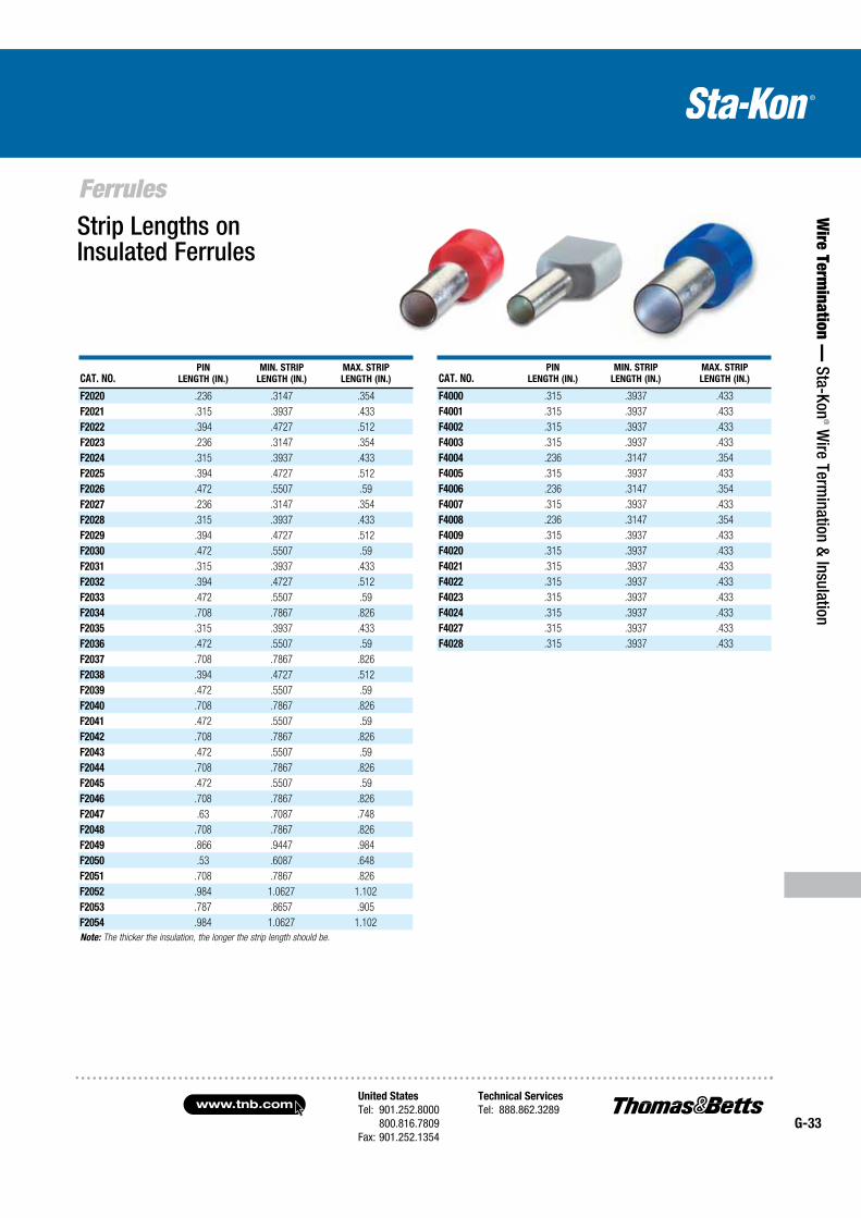
United States
Tel: 901.252.8000 800.816.7809Fax: 901.252.1354
Technical Services
Tel: 888.862.3289www.tnb.com
G-33
Ferrules
Wire Term
ination — Sta-Kon
® Wire Term
ination & Insulation
CAT. NO.PIN
LENGTH (IN.)
MIN. STRIP
LENGTH (IN.)
MAX. STRIP
LENGTH (IN.)
F2020 .236 .3147 .354
F2021 .315 .3937 .433
F2022 .394 .4727 .512
F2023 .236 .3147 .354
F2024 .315 .3937 .433
F2025 .394 .4727 .512
F2026 .472 .5507 .59
F2027 .236 .3147 .354
F2028 .315 .3937 .433
F2029 .394 .4727 .512
F2030 .472 .5507 .59
F2031 .315 .3937 .433
F2032 .394 .4727 .512
F2033 .472 .5507 .59
F2034 .708 .7867 .826
F2035 .315 .3937 .433
F2036 .472 .5507 .59
F2037 .708 .7867 .826
F2038 .394 .4727 .512
F2039 .472 .5507 .59
F2040 .708 .7867 .826
F2041 .472 .5507 .59
F2042 .708 .7867 .826
F2043 .472 .5507 .59
F2044 .708 .7867 .826
F2045 .472 .5507 .59
F2046 .708 .7867 .826
F2047 .63 .7087 .748
F2048 .708 .7867 .826
F2049 .866 .9447 .984
F2050 .53 .6087 .648
F2051 .708 .7867 .826
F2052 .984 1.0627 1.102
F2053 .787 .8657 .905
F2054 .984 1.0627 1.102
Note: The thicker the insulation, the longer the strip length should be.
CAT. NO.PIN
LENGTH (IN.)
MIN. STRIP
LENGTH (IN.)
MAX. STRIP
LENGTH (IN.)
F4000 .315 .3937 .433
F4001 .315 .3937 .433
F4002 .315 .3937 .433
F4003 .315 .3937 .433
F4004 .236 .3147 .354
F4005 .315 .3937 .433
F4006 .236 .3147 .354
F4007 .315 .3937 .433
F4008 .236 .3147 .354
F4009 .315 .3937 .433
F4020 .315 .3937 .433
F4021 .315 .3937 .433
F4022 .315 .3937 .433
F4023 .315 .3937 .433
F4024 .315 .3937 .433
F4027 .315 .3937 .433
F4028 .315 .3937 .433
Strip Lengths on Insulated Ferrules
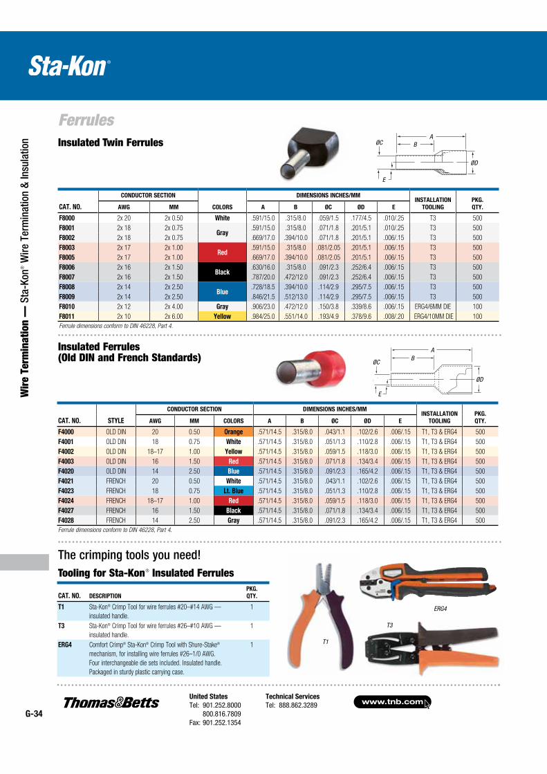
www.tnb.comUnited States
Tel: 901.252.8000 800.816.7809Fax: 901.252.1354
Technical Services
Tel: 888.862.3289G-34
Ferrules
Wir
e Te
rmin
atio
n —
Sta
-Kon
® W
ire T
erm
inat
ion
& In
sula
tion
T1
Insulated Twin Ferrules
Insulated Ferrules (Old DIN and French Standards)
T3
ERG4
The crimping tools you need!Tooling for Sta-Kon® Insulated Ferrules
CAT. NO.
CONDUCTOR SECTION
COLORS
DIMENSIONS INCHES/MMINSTALLATION
TOOLING
PKG.
QTY.AWG MM A B ØC ØD E
F8000 2x 20 2x 0.50 White .591/15.0 .315/8.0 .059/1.5 .177/4.5 .010/.25 T3 500
F8001 2x 18 2x 0.75Gray
.591/15.0 .315/8.0 .071/1.8 .201/5.1 .010/.25 T3 500
F8002 2x 18 2x 0.75 .669/17.0 .394/10.0 .071/1.8 .201/5.1 .006/.15 T3 500
F8003 2x 17 2x 1.00Red
.591/15.0 .315/8.0 .081/2.05 .201/5.1 .006/.15 T3 500
F8005 2x 17 2x 1.00 .669/17.0 .394/10.0 .081/2.05 .201/5.1 .006/.15 T3 500
F8006 2x 16 2x 1.50Black
.630/16.0 .315/8.0 .091/2.3 .252/6.4 .006/.15 T3 500
F8007 2x 16 2x 1.50 .787/20.0 .472/12.0 .091/2.3 .252/6.4 .006/.15 T3 500
F8008 2x 14 2x 2.50Blue
.728/18.5 .394/10.0 .114/2.9 .295/7.5 .006/.15 T3 500
F8009 2x 14 2x 2.50 .846/21.5 .512/13.0 .114/2.9 .295/7.5 .006/.15 T3 500
F8010 2x 12 2x 4.00 Gray .906/23.0 .472/12.0 .150/3.8 .339/8.6 .006/.15 ERG4/6MM DIE 100
F8011 2x 10 2x 6.00 Yellow .984/25.0 .551/14.0 .193/4.9 .378/9.6 .008/.20 ERG4/10MM DIE 100
Ferrule dimensions conform to DIN 46228, Part 4.
CAT. NO. STYLE
CONDUCTOR SECTION DIMENSIONS INCHES/MMINSTALLATION
TOOLING
PKG.
QTY.AWG MM COLORS A B ØC ØD E
F4000 OLD DIN 20 0.50 Orange .571/14.5 .315/8.0 .043/1.1 .102/2.6 .006/.15 T1, T3 & ERG4 500
F4001 OLD DIN 18 0.75 White .571/14.5 .315/8.0 .051/1.3 .110/2.8 .006/.15 T1, T3 & ERG4 500
F4002 OLD DIN 18–17 1.00 Yellow .571/14.5 .315/8.0 .059/1.5 .118/3.0 .006/.15 T1, T3 & ERG4 500
F4003 OLD DIN 16 1.50 Red .571/14.5 .315/8.0 .071/1.8 .134/3.4 .006/.15 T1, T3 & ERG4 500
F4020 OLD DIN 14 2.50 Blue .571/14.5 .315/8.0 .091/2.3 .165/4.2 .006/.15 T1, T3 & ERG4 500
F4021 FRENCH 20 0.50 White .571/14.5 .315/8.0 .043/1.1 .102/2.6 .006/.15 T1, T3 & ERG4 500
F4023 FRENCH 18 0.75 Lt. Blue .571/14.5 .315/8.0 .051/1.3 .110/2.8 .006/.15 T1, T3 & ERG4 500
F4024 FRENCH 18–17 1.00 Red .571/14.5 .315/8.0 .059/1.5 .118/3.0 .006/.15 T1, T3 & ERG4 500
F4027 FRENCH 16 1.50 Black .571/14.5 .315/8.0 .071/1.8 .134/3.4 .006/.15 T1, T3 & ERG4 500
F4028 FRENCH 14 2.50 Gray .571/14.5 .315/8.0 .091/2.3 .165/4.2 .006/.15 T1, T3 & ERG4 500
Ferrule dimensions conform to DIN 46228, Part 4.
CAT. NO. DESCRIPTION
PKG.
QTY.
T1 Sta-Kon® Crimp Tool for wire ferrules #20–#14 AWG —
insulated handle.
1
T3 Sta-Kon® Crimp Tool for wire ferrules #26–#10 AWG —
insulated handle.
1
ERG4 Comfort Crimp® Sta-Kon® Crimp Tool with Shure-Stake®
mechanism, for installing wire ferrules #26–1/0 AWG.
Four interchangeable die sets included. Insulated handle.
Packaged in sturdy plastic carrying case.
1
ØD
ØC
ØD
ØCA
B
E
B
A
E
AB
E
ØC
ØD
AB
E
ØC
ØD
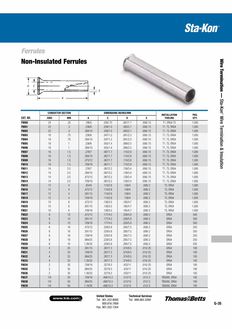
United States
Tel: 901.252.8000 800.816.7809Fax: 901.252.1354
Technical Services
Tel: 888.862.3289www.tnb.com
G-35
Ferrules
Wire Term
ination — Sta-Kon
® Wire Term
ination & Insulation
Non-Insulated Ferrules
CAT. NO.
CONDUCTOR SECTION DIMENSIONS INCHES/MMINSTALLATION
TOOLING
PKG.
QTY.AWG MM A C D E
F9000 24 .25 .196/5 .030/.75 .067/1.7 .006/.15 T1, ERG4 T3 1,000
F9001 22 .5 .236/6 .039/1.0 .083/2.1 .006/.15 T1, T3, ERG4 1,000
F9002 22 .5 .394/10 .039/1.0 .083/2.1 .006/.15 T1, T3, ERG4 1,000
F9003 18 .75 .236/6 .047/1.2 .091/2.3 .006/.15 T1, T3, ERG4 1,000
F9004 18 .75 .394/10 .047/1.2 .091/2.3 .006/.15 T1, T3, ERG4 1,000
F9005 18 1 .236/6 .055/1.4 .098/2.5 .006/.15 T1, T3, ERG4 1,000
F9006 18 1 .394/10 .055/1.4 .098/2.5 .006/.15 T1, T3, ERG4 1,000
F9007 16 1.5 .276/7 .067/1.7 .110/2.8 .006/.15 T1, T3, ERG4 1,000
F9008 16 1.5 .394/10 .067/1.7 .110/2.8 .006/.15 T1, T3, ERG4 1,000
F9009 16 1.5 .473/12 .067/1.7 .110/2.8 .006/.15 T1, T3, ERG4 1,000
F9010 16 1.5 .709/18 .067/1.7 .110/2.8 .006/.15 T1, T3, ERG4 1,000
F9011 14 2.5 .276/7 .087/2.2 .139/3.4 .006/.15 T1, T3, ERG4 1,000
F9012 14 2.5 .394/10 .087/2.2 .139/3.4 .006/.15 T1, T3, ERG4 1,000
F9013 14 2.5 .472/12 .087/2.2 .139/3.4 .006/.15 T1, T3, ERG4 1,000
F9014 14 2.5 .709/18 .087/2.2 .139/3.4 .006/.15 T1, T3, ERG4 1,000
F9015 12 4 .354/9 .110/2.8 .158/4 .008/.2 T3, ERG4 1,000
F9016 12 4 .472/12 .110/2.8 .158/4 .008/.2 T3, ERG4 1,000
F9017 12 4 .591/15 .110/2.8 .158/4 .008/.2 T3, ERG4 1,000
F9018 12 4 .709/18 .110/2.8 .158/4 .008/.2 T3, ERG4 1,000
F9019 10 6 .472/12 .138/3.5 .185/4.7 .008/.2 T3, ERG4 1,000
F9020 10 6 .591/15 .138/3.5 .185/4.7 .008/.2 T3, ERG4 1,000
F9021 10 6 .709/18 .138/3.5 .185/4.7 .008/.2 T3, ERG4 1,000
F9022 8 10 .472/12 .177/4.5 .228/5.8 .008/.2 ERG4 500
F9023 8 10 .591/15 .177/4.5 .228/5.8 .008/.2 ERG4 500
F9024 8 10 .709/18 .177/4.5 .228/5.8 .008/.2 ERG4 500
F9025 6 16 .472/12 .228/5.8 .295/7.5 .008/.2 ERG4 250
F9026 6 16 .591/15 .228/5.8 .295/7.5 .008/.2 ERG4 250
F9027 6 16 .709/18 .228/5.8 .295/7.5 .008/.2 ERG4 250
F9028 6 16 .984/25 .228/5.8 .295/7.5 .008/.2 ERG4 250
F9029 6 16 1.26/32 .228/5.8 .295/7.5 .008/.2 ERG4 250
F9030 4 25 .591/15 .287/7.3 .374/9.5 .010/.25 ERG4 100
F9031 4 25 .709/18 .287/7.3 .374/9.5 .010/.25 ERG4 100
F9032 4 25 .984/25 .287/7.3 .374/9.5 .010/.25 ERG4 100
F9033 4 25 1.26/32 .287/7.3 .374/9.5 .010/.25 ERG4 100
F9034 2 35 .709/18 .327/8.3 .433/11 .010/.25 ERG4 100
F9035 2 35 .984/25 .327/8.3 .433/11 .010/.25 ERG4 100
F9036 2 35 1.26/32 .327/8.3 .433/11 .010/.25 ERG4 100
F9037 1/0 50 .709/18 .406/10.3 .512/13 .012/.3 TB5095, ERG4 100
F9038 1/0 50 .984/25 .406/10.3 .512/13 .012/.3 TB5095, ERG4 100
F9039 1/0 50 1.18/30 .406/10.3 .512/13 .012/.3 TB5095, ERG4 100
A
E
CD
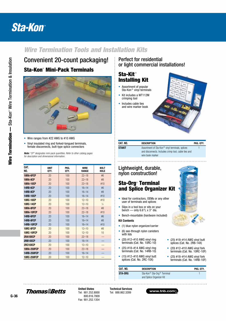
www.tnb.comUnited States
Tel: 901.252.8000 800.816.7809Fax: 901.252.1354
Technical Services
Tel: 888.862.3289G-36
Wire Termination Tools and Installation Kits
Wir
e Te
rmin
atio
n —
Sta
-Kon
® W
ire T
erm
inat
ion
& In
sula
tion
Ideal for contractors, OEMs or any other user of terminals and splices
Slips in a tool box or sits on your bench — only 6.6"L x 3" dia.
Bench-mountable (hardware included)
Kit Contents
(1) blue nylon organizer/carrier
(6) see-through nylon canisters with lids
(20) #12–#10 AWG vinyl ring terminals (Cat. No. 10RC-10)
(25) #18–#14 AWG vinyl ring terminals (Cat. No. 14RB-10)
(15) #12–#10 AWG vinyl butt splices (Cat. No. 2RC-10X)
Lightweight, durable, nylon construction!
Sta-Kit ®
Installing Kit
Convenient 20-count packaging!Sta-Kon® Mini-Pack Terminals
Wire ranges from #22 AWG to #10 AWG
Vinyl insulated ring and forked-tongued terminals, female disconnects, butt-type splice connectors
Note: “CP” designates mini-pack quantities. Refer to other catalog pages
for description and dimensional information.
Perfect for residential or light commercial installations!
(25) #18–#14 AWG vinyl butt splices (Cat. No. 2RB-14X)
(20) #12–#10 AWG vinyl fork terminals (Cat. No. 10RC-10F)
(25) #18–#14 AWG vinyl fork terminals (Cat. No. 14RB-10F)
Assortment of popular Sta-Kon ® vinyl terminals
Kit includes a WT112M crimping tool
Includes cable ties and wire marker book
CAT.
NO.UNIT
QTY.
PKG.
QTY.
WIRE
RANGE
BOLT
HOLE
18RA-6FCP 20 100 22–18 #6
18RA-8CP 20 100 22–18 #8
18RA-10CP 20 100 22–18 #10
14RB-6CP 20 100 16–14 #6
14RB-8CP 20 100 16–14 #8
14RB-10CP 20 100 16–14 #10
10RC-10CP 20 100 12–10 #10
10RC-14CP 20 100 12–10 1⁄4
18RA-8FCP 20 100 22–18 #8
18RA-10FCP 20 100 22–18 #10
14RB-6FCP 20 100 16–14 #6
14RB-8FCP 20 100 16–14 #8
14RB-10FCP 20 100 16–14 #10
10RC-8FCP 20 100 12–10 #8
10RC-10FCP 20 100 12–10 10
2RA18XCP 20 100 22–18 —
2RB14XCP 20 100 16–14 —
2RC10XCP 20 100 12–10 —
18RA-250FCP 20 100 22–18 —
14RB-250FCP 20 100 16–14 —
10RC-250FCP 20 100 12–10 —
CAT. NO. DESCRIPTION PKG. QTY.
STAKIT Assortment of Sta-Kon ® vinyl terminals, splices
and disconnects. Includes crimp tool, cable ties and
wire book marker
1
CAT. NO. DESCRIPTION PKG. QTY.
STA-ORG Sta-Kon ® Sta-Org ® Terminal
and Splice Organizer Kit
1
Sta-Org® Terminal and Splice Organizer Kit
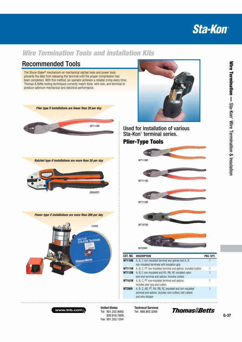
United States
Tel: 901.252.8000 800.816.7809Fax: 901.252.1354
Technical Services
Tel: 888.862.3289www.tnb.com
G-37
Wire Termination Tools and Installation Kits
Wire Term
ination — Sta-Kon
® Wire Term
ination & Insulation
Used for installation of various Sta-Kon® terminal series.Plier-Type Tools
WT112M
WT111M
WT110M
WT161M
WT2000
Recommended ToolsThe Shure-Stake® mechanism on mechanical ratchet tools and power tools prevents the dies from releasing the terminal until the proper compression has been completed. With this method, an operator achieves a reliable crimp every time. Thomas & Betts tooling techniques correctly match tools, wire size, and terminal to produce optimum mechanical and electrical performance.
Plier type if installations are fewer than 20 per day
Power type if installations are more than 200 per day
12050
ERG4001
Ratchet type if installations are more than 20 per day
WT112M
CAT. NO. DESCRIPTION PKG. QTY.
WT110M A, B, C non-insulated terminal and splices and A, B
non-insulated terminals with insulation grip
1
WT111M A, B, C, PT non-insulated terminal and splices; includes cutters 1
WT112M A, B, C non-insulated and RA, RB, RC insulated nylon
and vinyl terminal and splices; includes cutters
1
WT161M A, B, C, PT non-insulated terminal and splices;
includes plier grip and cutters
1
WT2000 A, B, C, AB, PT, RA, RB, RC insulated and non-insulated
terminal and splices; includes wire cutters, bolt cutters
and wire stripper
1

www.tnb.comUnited States
Tel: 901.252.8000 800.816.7809Fax: 901.252.1354
Technical Services
Tel: 888.862.3289G-38
Wire Termination Tools and Installation Kits
Wir
e Te
rmin
atio
n —
Sta
-Kon
® W
ire T
erm
inat
ion
& In
sula
tion Redesigned family of termination tools sets
a new standard for manual crimping tools!
Comfort Crimp® Compression Tools
Color-coded die nests (left and right side) provided for proper crimping of
insulated terminals Shure-Stake® mechanism ensures a proper crimp every time
Ergonomically advanced, soft, over-molded handle grips reduce strain and
enhance user comfort Requires the lowest handle force of any tool in its class — 25% less than the previous
generation of Comfort Crimp ® tools
Crimp-Assist ® foot provides stability when work surface leverage is
needed to crimp larger connectors
Perfect for OEM, MRO and field use
UL Listed for use with Sta-Kon® connectors
Shure-Stake® mechanism ensures a complete crimp cycle before release for a proper crimp every time
Color-coded die nests for easy matching with Sta-Kon® insulated terminals
Creates integrity dots for quick verification of proper crimp
Advanced manufacturing methods for improved durability and tool life
Lanyard hole in handle for easy tethering to workstation
Calibration service available through T&B Tool Services
Sta-Kon® Comfort Crimp® Compression Tools previously set the standard for manual crimp tools. Now, Thomas & Betts engineers have made a great line of tools even better with the newly redesigned Sta-Kon® Comfort Crimp® Compression Tools. We kept all the performance features that made the tools industry leaders such as the Shure-Stake® mechanism and interchangeable dies with color-coded die nests, and focused on creating the best possible user experience in terms of comfort and reduction of strain.
Ergonomic handles position the user’s hands correctly to minimize the risk of strain, and soft, over-molded grips cushion fingers and palm for user comfort. A new Crimp-Assist™ foot stabilizes the tool when the user needs to place it on a work surface for leverage to crimp larger connectors. Best of all, the redesigned Comfort Crimp® tools require 25% less handle force to complete the crimp cycle than the previous generation — and up to 75% less handle force than competing tools!
Requiring the lowest handle force of any tool in its class, the new Comfort Crimp® family provides maximum comfort to installers, without sacrificing the durability or performance associated with Thomas & Betts tools.
The most comfortable crimp available from a manual compression tool!
CAT. NO. FOR USE WITH STA-KON® SERIES
PKG.
QTY.
ERG4001 RA, RB, RC nylon & vinyl terminals, splices & disconnects 1
ERG4002 A, B, C non-insulated terminals, splices, disconnects 1
ERG4004 A, B and C flag terminals 1
ERG4005 B, C, D, E non-insulated terminals, splices,
(D & E tubular only)
1
ERG4006 RA, RB .110 disconnects and RZ Terminals 1
ERG4007 RD & RE insulated terminals (tubular only) 1
ERG4008 Non-insulated terminals #8–1/0 AWG (tubular only) 1
Note: Contact Tool Services for gauging.
ERG4002
ERG4004
ERG4005
ERG4007
ERG4008

United States
Tel: 901.252.8000 800.816.7809Fax: 901.252.1354
Technical Services
Tel: 888.862.3289www.tnb.com
G-39
Wire Termination Tools and Installation Kits
Wire Term
ination — Sta-Kon
® Wire Term
ination & Insulation
WT3185 Ratchet Hand Tool
WT129 Flag Terminal Type Hand Tool
ERG4006 Hand Tool
WT1377 Ratchet Hand Tool
Correct compression every time — the Shure-Stake® mechanism principle prevents opening of the handles until full staking action is completed. Installs self-insulated and non-insulated Sta-Kon® terminal series in the #26–#10 AWG wire range.
WT2130A Ratchet Hand Tool
ERG4255 Ratchet Hand Tool
CAT. NO. FOR USE WITH STA-KON® SERIES
PKG.
QTY.
WT1377 NW ring terminals 1
CAT. NO. FOR USE WITH STA-KON® SERIES
PKG.
QTY.
ERG4006 RZ terminals/splices
RA, RB .110 insulated disconnects
1
CAT. NO. FOR USE WITH STA-KON® SERIES
PKG.
QTY.
ERG4255 RA, RB, RC heat-shrinkable nylon-insulated
terminals, butt splices, and disconnects
1
CAT. NO. FOR USE WITH STA-KON® SERIES
PKG.
QTY.
WT129 D, E, F & G non-insulated flag terminals 1
CAT. NO. FOR USE WITH STA-KON® SERIES
PKG.
QTY.
WT3185 For #8 AWG to 250 kcmil non-insulated Sta-Kon® Terminals 1
Note: For gauging information, contact Tool Services.
CAT. NO. FOR USE WITH STA-KON® SERIES
PKG.
QTY.
WT2130A RC, RBC and RD insulated terminals, RC6, RP7 wire joints 1
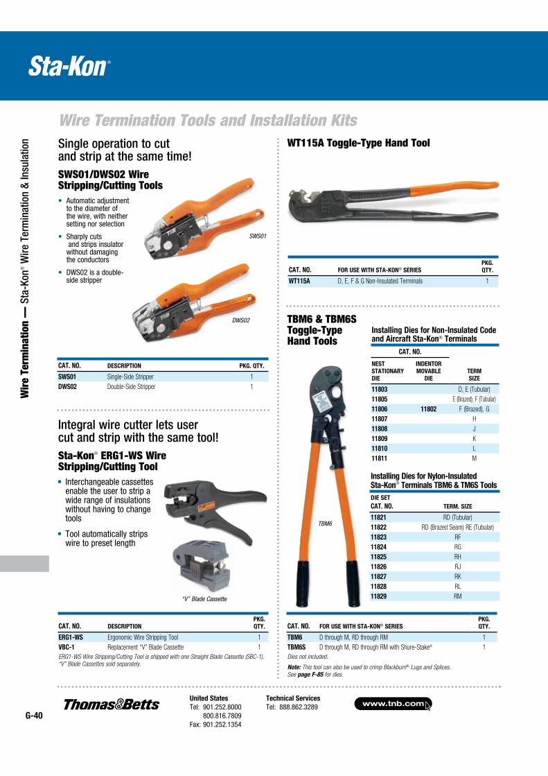
Wire Termination Tools and Installation Kits
www.tnb.comUnited States
Tel: 901.252.8000 800.816.7809Fax: 901.252.1354
Technical Services
Tel: 888.862.3289G-40
Wir
e Te
rmin
atio
n —
Sta
-Kon
® W
ire T
erm
inat
ion
& In
sula
tion WT115A Toggle-Type Hand Tool
Installing Dies for Non-Insulated Code and Aircraft Sta-Kon® Terminals
CAT. NO.
TERM
SIZE
NEST
STATIONARY
DIE
INDENTOR
MOVABLE
DIE
11803 D, E (Tubular)
11805 E (Brazed), F (Tubular)
11806 11802 F (Brazed), G
11807 H
11808 J
11809 K
11810 L
11811 M
TBM6 & TBM6S Toggle-Type Hand Tools
TBM6
CAT. NO. FOR USE WITH STA-KON® SERIES
PKG.
QTY.
TBM6 D through M, RD through RM 1
TBM6S D through M, RD through RM with Shure-Stake® 1
Dies not included.
Note: This tool can also be used to crimp Blackburn® Lugs and Splices.
See page F-85 for dies.
Interchangeable cassettes enable the user to strip a wide range of insulations without having to change tools
Tool automatically strips wire to preset length
Integral wire cutter lets user cut and strip with the same tool!Sta-Kon® ERG1-WS Wire Stripping/Cutting Tool
CAT. NO. DESCRIPTION
PKG.
QTY.
ERG1-WS Ergonomic Wire Stripping Tool 1
VBC-1 Replacement “V” Blade Cassette 1
ERG1-WS Wire Stripping/Cutting Tool is shipped with one Straight Blade Cassette (SBC-1).
“V” Blade Cassettes sold separately.
“V” Blade Cassette
CAT. NO. DESCRIPTION PKG. QTY.
SWS01 Single-Side Stripper 1
DWS02 Double-Side Stripper 1
Single operation to cut and strip at the same time!SWS01/DWS02 Wire Stripping/Cutting Tools
Automatic adjustment to the diameter of the wire, with neither setting nor selection
Sharply cuts and strips insulator without damaging the conductors
DWS02 is a double- side stripper
SWS01
DWS02
CAT. NO. FOR USE WITH STA-KON® SERIES
PKG.
QTY.
WT115A D, E, F & G Non-Insulated Terminals 1
Installing Dies for Nylon-Insulated Sta-Kon® Terminals TBM6 & TM6S Tools
DIE SET
CAT. NO. TERM. SIZE
11821 RD (Tubular)
11822 RD (Brazed Seam) RE (Tubular)
11823 RF
11824 RG
11825 RH
11826 RJ
11827 RK
11828 RL
11829 RM
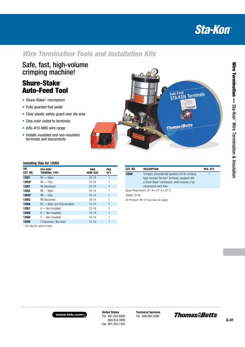
Wire Termination Tools and Installation Kits
United States
Tel: 901.252.8000 800.816.7809Fax: 901.252.1354
Technical Services
Tel: 888.862.3289www.tnb.com
G-41
Wire Term
ination — Sta-Kon
® Wire Term
ination & Insulation
Safe, fast, high-volume crimping machine!
Shure-Stake® Auto-Feed Tool
Shure-Stake® mechanism
Fully guarded foot pedal
Clear plastic safety guard over die area
Dies color coded to terminals
#26–#10 AWG wire range
Installs insulated and non-insulated terminals and disconnects
Installing Dies for 12050
DIE
CAT. NO.STA-KON®
TERMINAL TYPE
AWG
WIRE SIZE
PKG.
QTY.
12051 RA — Nylon 22–18 1
12054* RA — Vinyl 22–18 1
12061 RA Disconnect 22–18 1
12052 RB — Nylon 16–14 1
12055* RB — Vinyl 16–14 1
12062 RB Disconnect 16–14 1
12056 RC — Nylon and Vinyl Insulated 12–10 1
12057 A — Non-Insulated 22–18 1
12058 B — Non-Insulated 16–14 1
12059 C — Non-Insulated 12–10 1
12060 C Disconnect, Non-Insul. 12–10 1
* Can also be used on nylon.
CAT. NO. DESCRIPTION PKG. QTY.
12050 Compact, pneumatically operated unit for crimping
tape-mounted Sta-Kon® terminals; equipped with
a Shure-Stake® mechanism, which ensures a full
compression each time
1
Space Requirement: 30" W x 20" H x 20" D
Weight: 55 lbs.
Air Pressure: 90–125 psi input air supply

www.tnb.comUnited States
Tel: 901.252.8000 800.816.7809Fax: 901.252.1354
Technical Services
Tel: 888.862.3289G-42
Wire Termination Tools and Installation Kits
Wir
e Te
rmin
atio
n —
Sta
-Kon
® W
ire T
erm
inat
ion
& In
sula
tion
Interchangeable dies can be quickly changed to crimp non-insulated and insulated terminals up to #6 AWG
Dies are the same as our hand tools — crimps will be exactly the same between Sta-Kon® hand tools such as our ERG4001 and the BAT22-6
360° rotating head gives the user the added flexibility when crimping hard-to-reach connections
Short cycle time equates to crimping times of less than two seconds
Quick, lightweight, and maneuverable
NiCd battery operation provides long-lasting battery life to complete up to 150 crimps on a single charge
Extra battery and charger are included with the tool, ensuring round-the-clock operation
Battery charger provides full battery life in under an hour
Linear crimping motion gives a symmetric, high-quality crimp every time
11⁄2 tons of grip that weighs less than three pounds!Battery-Powered Crimping Tool — BAT22-6
T&B’s newest battery-powered tool is fast and portable for making high-volume and difficult-to-reach terminal installations in a snap. The Sta-Kon® BAT22-6 delivers 1.5 tons of crimping force with an easy, pushbutton trigger. The lightweight, ergonomic design minimizes the risk of repetitive motion injuries that can occur with traditional hand crimping tools. And at less than three pounds, one-hand operation is easy while still packing enough power to crimp up to #6 AWG terminals in seconds.
CAT. NO. DESCRIPTION
PKG.
QTY.
BAT22-6 Battery Crimping Tool, 1.5 Ton with 120-VAC Charger 1
Crimp Dies*
DIE2001 Insulated #22–#10 AWG Sta-Kon® Terminals 1
DIE2002 Non-Insulated #22–#10 AWG Sta-Kon® Terminals 1
DIE2005 Non-Insulated #16–#14/#12–#10/#8–#6 Sta-Kon® Terminals
(Tubular Only)
1
DIE2007 Insulated #8–#6 AWG Sta-Kon® Terminals (Tubular Only) 1
*Dies sold separately.
Note: Battery-powered tools BPI42300CR, BPLT6BSCR and BPLT62BSCR can also
be used to crimp non-insulated Sta-Kon® terminals. See pages F-86–F-88.
Included Accessories
Sturdy, plastic carrying case for portability
Two 9.6V NiCd batteries and battery charger
Sturdy tray for convenient storage of crimp dies
Uses the exact dies of the Comfort Crimp line of ergonomic tools for Sta-Kon® and Dragon Tooth® terminals.
Easy to rotate with your wrist — delivers fast and effective crimping power.
1.25 tons output force at 100 psi
Crimps #22–#6 AWG terminals
Installs Sta-Kon® terminals as well as ferrules and Dragon Tooth® connectors
Interchangeable dies
Open yoke enables easy access to insert and remove terminals for crimping
Portable heavy-duty air tool.PAIR22-6 Heavy-Duty Portable Air Crimp Tool
CAT. NO. DESCRIPTION PKG. QTY.
PAIR22-6 Open yoke, hand actuated 1
Crimp Dies*
DIE2001 Insulated #22–#10 AWG Sta-Kon® Terminals 1
DIE2002 Non-Insulated #22–#10 AWG Sta-Kon® Terminals 1
DIE2005 Non-Insulated #16–#10/#8–#6 Sta-Kon® Terminals (Tubular Only) 1
DIE2007 Insulated #8–#6 AWG Sta-Kon® Terminals (Tubular Only) 1
* Dies sold separately.
Note: The dies for the BAIR22-6, PAIR22-6 and BAT22-6 are interchangeable.
Note: Battery-powered tools BPI42300CR, BPLT6BSCR and BPLT62BSCR can also be used
to crimp non-insulated Sta-Kon® terminals. See pages F-86–F-88.
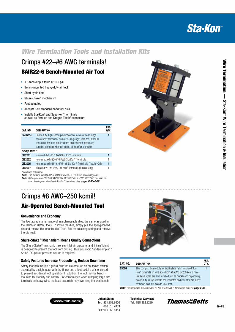
United States
Tel: 901.252.8000 800.816.7809Fax: 901.252.1354
Technical Services
Tel: 888.862.3289www.tnb.com
G-43
Wire Termination Tools and Installation Kits
Wire Term
ination — Sta-Kon
® Wire Term
ination & Insulation
Crimps #8 AWG–250 kcmil!Air-Operated Bench-Mounted Tool
CAT. NO. DESCRIPTION
PKG.
QTY.
BAIR22-6 Heavy-duty, high-speed production tool installs a wide range
of Sta-Kon® terminals, from #26–#6 gauge; uses the DIE2000
series dies for both non-insulated and insulated terminals;
supplied complete with foot pedal, air hose/air lubricator
1
Crimp Dies*
DIE2001 Insulated #22–#10 AWG Sta-Kon® Terminals 1
DIE2002 Non-Insulated #22–#10 AWG Sta-Kon® Terminals 1
DIE2005 Non-Insulated #16–#10/#8–#6 Sta-Kon® Terminals (Tubular Only) 1
DIE2007 Insulated #8–#6 AWG Sta-Kon® Terminals (Tubular Only) 1
* Dies sold separately.
Note: The dies for the BAIR22-6, PAIR22-6 and BAT22-6 are interchangeable.
Note: Battery-powered tools BPI42300CR, BPLT6BSCR and BPLT62BSCR can also be
used to crimp non-insulated Sta-Kon ® terminals. See pages F-86–F-88.
Crimps #22–#6 AWG terminals!BAIR22-6 Bench-Mounted Air Tool
1.8 tons output force at 100 psi
Bench-mounted heavy-duty air tool
Short cycle time
Shure-Stake® mechanism
Foot actuated
Accepts T&B standard hand tool dies
Installs Sta-Kon® and Spec-Kon® terminals as well as ferrules and Dragon Tooth® connectors
CAT. NO. DESCRIPTION
PKG.
QTY.
25000 This compact heavy-duty air tool installs nylon insulated Sta-
Kon® terminals on wire sizes from #8 AWG to 250 kcmil; non-
insulated styles are also installed just as quickly and dependably;
heavy-duty air tool installs non-insulated and insulated Sta-Kon®
terminals from #8 AWG to 250 kcmil
1
Note: This tool uses the same dies as the TBM6 and TBM6S hand tools on page F-85.
Convenience and Economy
The tool accepts a full range of interchangeable dies, the same as used in the TBM6 or TBM6S tools. To install the dies, simply pull the spring-loaded pin and remove the indentor die. Then, flex the retaining spring and remove the die nest.
Shure-Stake ® Mechanism Means Quality Connections
The Shure-Stake ® mechanism senses inlet air pressure, and if insufficient, is designed to prevent the tool from cycling. Thus you avoid “undercrimping.” An 85–90-psi air pressure source is required.
Safety Features Increase Productivity, Reduce Downtime
Safety features include a guard over the die area, an air shutdown switch activated by a slight push with the finger and a foot pedal that’s enclosed to prevent accidental tool operation. In addition, the tool may be bench-mounted for stability and control. For convenience when crimping large size terminals on heavy wire, the head assembly may overhang the workbench.
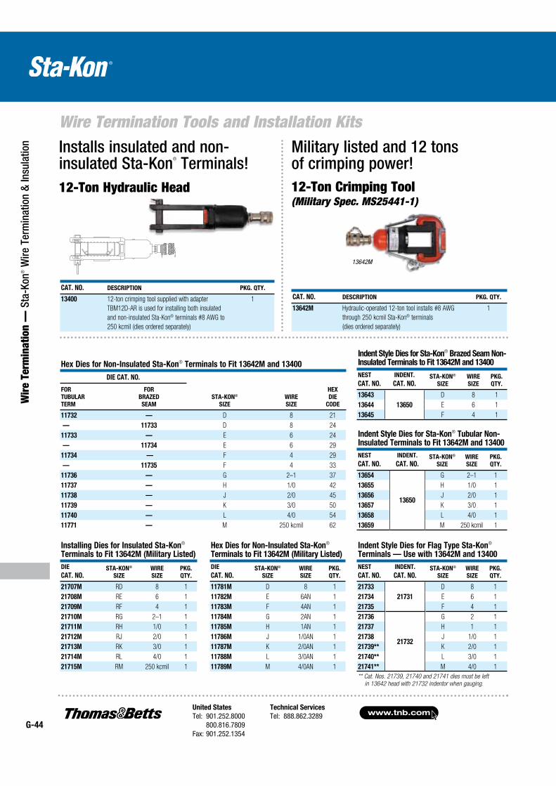
www.tnb.comUnited States
Tel: 901.252.8000 800.816.7809Fax: 901.252.1354
Technical Services
Tel: 888.862.3289G-44
Wire Termination Tools and Installation Kits
Wir
e Te
rmin
atio
n —
Sta
-Kon
® W
ire T
erm
inat
ion
& In
sula
tion
CAT. NO. DESCRIPTION PKG. QTY.
13400 12-ton crimping tool supplied with adapter
TBM12D-AR is used for installing both insulated
and non-insulated Sta-Kon® terminals #8 AWG to
250 kcmil (dies ordered separately)
1
Installs insulated and non-insulated Sta-Kon® Terminals!12-Ton Hydraulic Head
Military listed and 12 tons of crimping power!12-Ton Crimping Tool (Military Spec. MS25441-1)
13642M
Hex Dies for Non-Insulated Sta-Kon® Terminals to Fit 13642M and 13400
DIE CAT. NO.
STA-KON®
SIZE
WIRE
SIZE
HEX
DIE
CODE
FOR
TUBULAR
TERM
FOR
BRAZED
SEAM
11732 — D 8 21
— 11733 D 8 24
11733 — E 6 24
— 11734 E 6 29
11734 — F 4 29
— 11735 F 4 33
11736 — G 2–1 37
11737 — H 1/0 42
11738 — J 2/0 45
11739 — K 3/0 50
11740 — L 4/0 54
11771 — M 250 kcmil 62
CAT. NO. DESCRIPTION PKG. QTY.
13642M Hydraulic-operated 12-ton tool installs #8 AWG
through 250 kcmil Sta-Kon® terminals
(dies ordered separately)
1
Installing Dies for Insulated Sta-Kon® Terminals to Fit 13642M (Military Listed)
DIE
CAT. NO.STA-KON®
SIZE
WIRE
SIZE
PKG.
QTY.
21707M RD 8 1
21708M RE 6 1
21709M RF 4 1
21710M RG 2–1 1
21711M RH 1/0 1
21712M RJ 2/0 1
21713M RK 3/0 1
21714M RL 4/0 1
21715M RM 250 kcmil 1
Hex Dies for Non-Insulated Sta-Kon® Terminals to Fit 13642M (Military Listed)
DIE
CAT. NO.STA-KON®
SIZE
WIRE
SIZE
PKG.
QTY.
11781M D 8 1
11782M E 6AN 1
11783M F 4AN 1
11784M G 2AN 1
11785M H 1AN 1
11786M J 1/0AN 1
11787M K 2/0AN 1
11788M L 3/0AN 1
11789M M 4/0AN 1
Indent Style Dies for Sta-Kon® Brazed Seam Non-Insulated Terminals to Fit 13642M and 13400
NEST
CAT. NO.
INDENT.
CAT. NO.STA-KON®
SIZE
WIRE
SIZE
PKG.
QTY.
13643 D 8 1
13644 13650 E 6 1
13645 F 4 1
Indent Style Dies for Sta-Kon® Tubular Non-Insulated Terminals to Fit 13642M and 13400
NEST
CAT. NO.
INDENT.
CAT. NO.STA-KON®
SIZE
WIRE
SIZE
PKG.
QTY.
13654
13650
G 2–1 1
13655 H 1/0 1
13656 J 2/0 1
13657 K 3/0 1
13658 L 4/0 1
13659 M 250 kcmil 1
Indent Style Dies for Flag Type Sta-Kon® Terminals — Use with 13642M and 13400
NEST
CAT. NO.
INDENT.
CAT. NO.STA-KON®
SIZE
WIRE
SIZE
PKG.
QTY.
21733 D 8 1
21734 21731 E 6 1
21735 F 4 1
21736
21732
G 2 1
21737 H 1 1
21738 J 1/0 1
21739** K 2/0 1
21740** L 3/0 1
21741** M 4/0 1
** Cat. Nos. 21739, 21740 and 21741 dies must be left
in 13642 head with 21732 indentor when gauging.
FORGED
STEEL
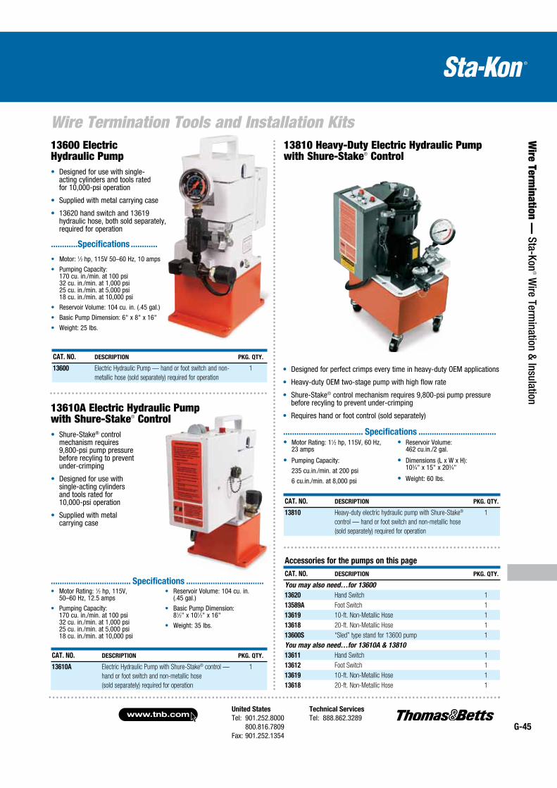
United States
Tel: 901.252.8000 800.816.7809Fax: 901.252.1354
Technical Services
Tel: 888.862.3289www.tnb.com
G-45
Wire Termination Tools and Installation Kits
Wire Term
ination — Sta-Kon
® Wire Term
ination & Insulation
13600 Electric Hydraulic Pump
Designed for use with single- acting cylinders and tools rated for 10,000-psi operation
Supplied with metal carrying case
13620 hand switch and 13619 hydraulic hose, both sold separately, required for operation
CAT. NO. DESCRIPTION PKG. QTY.
13600 Electric Hydraulic Pump — hand or foot switch and non-
metallic hose (sold separately) required for operation
1
13810 Heavy-Duty Electric Hydraulic Pump with Shure-Stake® Control
Motor: 1⁄2 hp, 115V 50–60 Hz, 10 amps
Pumping Capacity: 170 cu. in./min. at 100 psi 32 cu. in./min. at 1,000 psi 25 cu. in./min. at 5,000 psi 18 cu. in./min. at 10,000 psi
Reservoir Volume: 104 cu. in. (.45 gal.)
Basic Pump Dimension: 6" x 8" x 16"
Weight: 25 lbs.
............Specifications ............
Shure-Stake® control mechanism requires 9,800-psi pump pressure before recyling to prevent under-crimping
Designed for use with single-acting cylinders and tools rated for 10,000-psi operation
Supplied with metal carrying case
13610A Electric Hydraulic Pump with Shure-Stake® Control
CAT. NO. DESCRIPTION PKG. QTY.
13610A Electric Hydraulic Pump with Shure-Stake® control —
hand or foot switch and non-metallic hose
(sold separately) required for operation
1
Motor Rating: 1⁄2 hp, 115V, 50–60 Hz, 12.5 amps
Pumping Capacity: 170 cu. in./min. at 100 psi 32 cu. in./min. at 1,000 psi 25 cu. in./min. at 5,000 psi 18 cu. in./min. at 10,000 psi
Reservoir Volume: 104 cu. in. (.45 gal.)
Basic Pump Dimension: 81⁄2" x 101⁄2" x 16"
Weight: 35 lbs.
.................................... Specifications ...................................
Designed for perfect crimps every time in heavy-duty OEM applications
Heavy-duty OEM two-stage pump with high flow rate
Shure-Stake® control mechanism requires 9,800-psi pump pressure before recyling to prevent under-crimping
Requires hand or foot control (sold separately)
Motor Rating: 11⁄2 hp, 115V, 60 Hz, 23 amps
Pumping Capacity:
235 cu.in./min. at 200 psi
6 cu.in./min. at 8,000 psi
Reservoir Volume: 462 cu.in./2 gal.
Dimensions (L x W x H): 103⁄4" x 15" x 203⁄4"
Weight: 60 lbs.
.................................... Specifications ...................................
CAT. NO. DESCRIPTION PKG. QTY.
13810 Heavy-duty electric hydraulic pump with Shure-Stake®
control — hand or foot switch and non-metallic hose
(sold separately) required for operation
1
Accessories for the pumps on this page
CAT. NO. DESCRIPTION PKG. QTY.
You may also need…for 13600
13620 Hand Switch 1
13589A Foot Switch 1
13619 10-ft. Non-Metallic Hose 1
13618 20-ft. Non-Metallic Hose 1
13600S “Sled” type stand for 13600 pump 1
You may also need…for 13610A & 13810
13611 Hand Switch 1
13612 Foot Switch 1
13619 10-ft. Non-Metallic Hose 1
13618 20-ft. Non-Metallic Hose 1
www.tnb.comUnited States
Tel: 901.252.8000 800.816.7809Fax: 901.252.1354
Technical Services
Tel: 888.862.3289G-46
Wire Termination Technical Information
Wir
e Te
rmin
atio
n —
Sta
-Kon
® W
ire T
erm
inat
ion
& In
sula
tion
FINISH SUFFIX SPEC. TEMP. RATING
Gold Plate GP MIL-G-45204 Type II, Grade B, C, D, Class O 260˚ C
Nickel Plate NP QQ-N-290 Class 2, Grade G 260˚ C
Plain Finish PF None 150˚ C
Silver Plate SP MIL-T-16366 Type I or II, 400° F, 204° C 150˚ C
Platings/Finish
Electroplated-Tin is standard finish. All others require minimum order quantities and are generally not stocked. Alternative platings are as follows: Gold, Silver, Tin-Alloys, Nickel or plain finish. See table (below) for specification information.
Listing
Sta-Kon® Rings, Forks and Locking Forks are tested and listed to UL 486A, two-way splices to UL 486C, disconnects to UL 310 and all appli cable products to CSA 22.2.
Sta-Kon® Technical Data
TERMINALS & SPLICES
INSULATION RATING
UL® 94
FLAMMABILITY VOLTAGE TEMPERATURE
Nylon V-2 600V* 105° C
Vinyl V-0 600V* 105° C
Tefzel® V-0 600V* 150° C
Disconnects 300V 105° C
Non-Insulated — 600V 150º C
*1000V fixture or sign
Minimum pull-out test — UL 486A and UL 486C
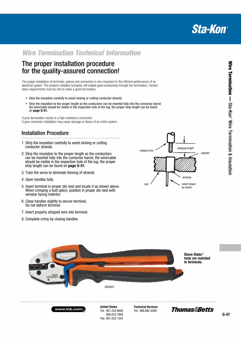
United States
Tel: 901.252.8000 800.816.7809Fax: 901.252.1354
Technical Services
Tel: 888.862.3289www.tnb.com
G-47
Wire Termination Technical Information
Wire Term
ination — Sta-Kon
® Wire Term
ination & Insulation
1. Strip the insulation carefully to avoid nicking or cutting conductor strands.
2. Strip the insulation to the proper length so the conductors can be inserted fully into the connector barrel; the wire/cable should be visible in the inspection hole of the lug; the proper strip length can be found on page G-51.
3. Train the wires to eliminate fanning of strands.
4. Open handles fully.
5. Insert terminal in proper die nest and locate it as shown above. When crimping a butt splice, position in proper die nest with window facing indentor.
6. Close handles slightly to secure terminal. Do not deform terminal.
7. Insert properly stripped wire into terminal.
8. Complete crimp by closing handles.
The proper installation procedure for the quality-assured connection!The proper installation of terminals, splices and connectors is very important to the efficient performance of an electrical system. The properly installed connector will enable good conductivity through the termination. Certain basic requirements must be met to make a good termination.
Strip the insulation carefully to avoid nicking or cutting conductor strands
Strip the insulation to the proper length so the conductors can be inserted fully into the connector barrel; the wire/cable should be visible in the inspection hole of the lug; the proper strip length can be found on page G-51.
A poor termination results in a high-resist ance connection. A poor connector installation may cause damage or failure of an entire system.
Shure-Stake® tools are matched to terminals.
ERG4001
stripped wire
rest
strippinglength
indentor
terminal
orient tongueas shown
Installation Procedure
stripping length
terminal
stripped wire
rest orient tongue as shown
indentor
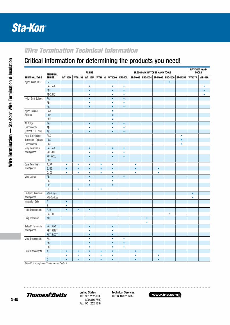
www.tnb.comUnited States
Tel: 901.252.8000 800.816.7809Fax: 901.252.1354
Technical Services
Tel: 888.862.3289G-48
Wire Termination Technical Information
Wir
e Te
rmin
atio
n —
Sta
-Kon
® W
ire T
erm
inat
ion
& In
sula
tion Critical information for determining the products you need!
TERMINAL TYPE
TERMINAL
SERIES
PLIERS ERGONOMIC RATCHET HAND TOOLS
RATCHET HAND
TOOLS
WT110M WT111M WT112M WT161M WT2000 ERG4001 ERG4002 ERG4004 ERG4005 ERG4006 ERG4255 WT1377 WT145A
Nylon Terminals RZ
RA, RAX
RB
RBC, RC
Nylon Butt Splices RA
RB
RC
Nylon Parallel
Splices
RAA
RBB
RCC
All Nylon
Disconnects
(except .110 size)
RA
RB
RC
Heat-Shrinkable RAS
Terminals, Splices, RBS
Disconnects RCS
Vinyl Terminals
and Splices
RA, RAA
RB, RBB
RC, RCC,
RBC
Bare Terminals
and Splices
A, AA
B, BB
C, CC
Wire Joints RB
RC
RP
PT
Hi-Temp Terminals
and Splices
NW-Rings
NW-Splices
Insulation Grip A
B
.110 Disconnects A, B
RA, RB
Flag Terminals AB
C
Tefzel® Terminals
and Splices
RAT, RAAT
RBT, RBBT
RCT, RCCT
Vinyl Disconnects RA
RB
RC
Bare Disconnects A
B
C
Tefzel ® is a registered trademark of DuPont.
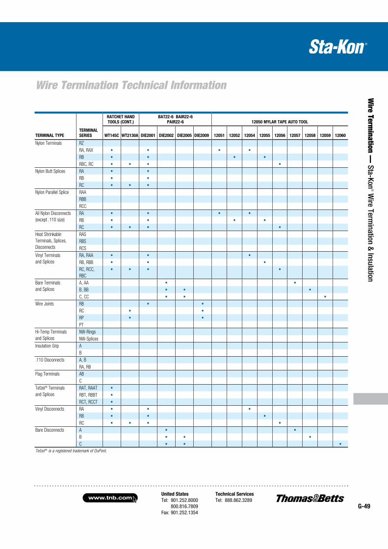
United States
Tel: 901.252.8000 800.816.7809Fax: 901.252.1354
Technical Services
Tel: 888.862.3289www.tnb.com
G-49
Wire Termination Technical Information
Wire Term
ination — Sta-Kon
® Wire Term
ination & Insulation
RATCHET HAND
TOOLS (CONT.)
BAT22-6 BAIR22-6
PAIR22-6 12050 MYLAR TAPE AUTO TOOL
TERMINAL TYPE
TERMINAL
SERIES WT145C WT2130A DIE2001 DIE2002 DIE2005 DIE2009 12051 12052 12054 12055 12056 12057 12058 12059 12060
Nylon Terminals RZ
RA, RAX
RB
RBC, RC
Nylon Butt Splices RA
RB
RC
Nylon Parallel Splice RAA
RBB
RCC
All Nylon Disconnects
(except .110 size)
RA
RB
RC
Heat Shrinkable
Terminals, Splices,
Disconnects
RAS
RBS
RCS
Vinyl Terminals
and Splices
RA, RAA
RB, RBB
RC, RCC,
RBC
Bare Terminals
and Splices
A, AA
B, BB
C, CC
Wire Joints RB
RC
RP
PT
Hi-Temp Terminals
and Splices
NW-Rings
NW-Splices
Insulation Grip A
B
.110 Disconnects A, B
RA, RB
Flag Terminals AB
C
Tefzel® Terminals
and Splices
RAT, RAAT
RBT, RBBT
RCT, RCCT
Vinyl Disconnects RA
RB
RC
Bare Disconnects A
B
C
Tefzel ® is a registered trademark of DuPont.
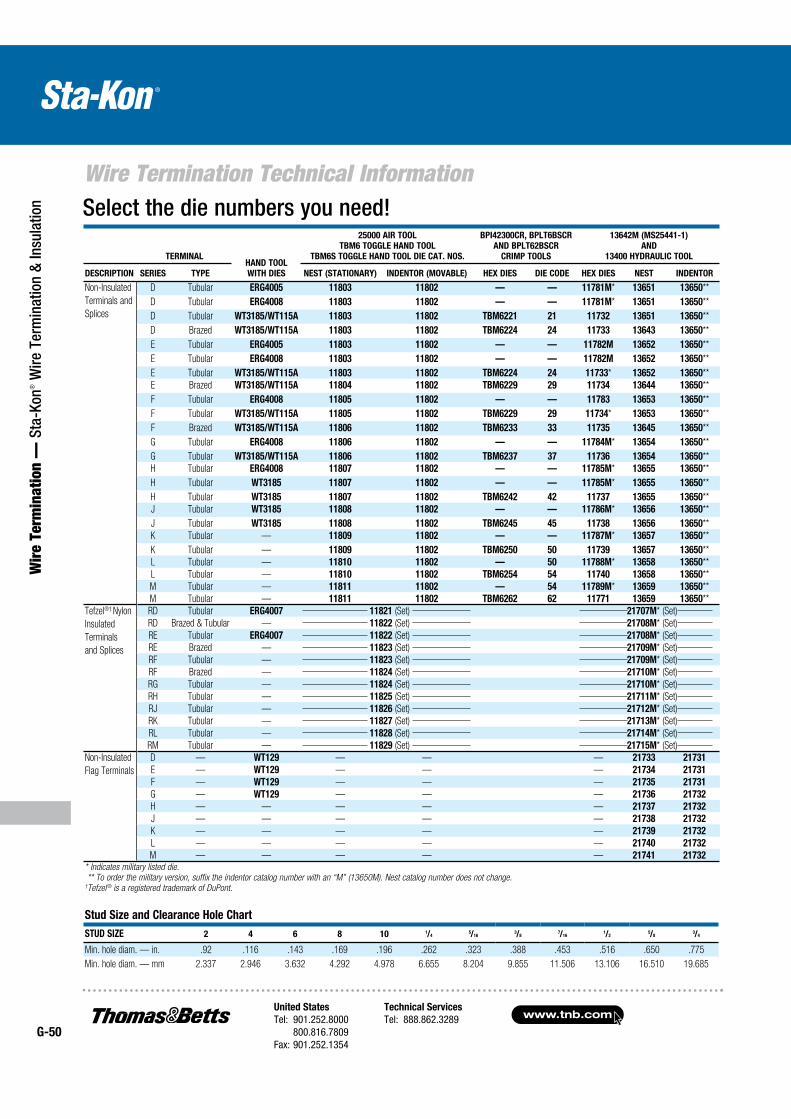
www.tnb.comUnited States
Tel: 901.252.8000 800.816.7809Fax: 901.252.1354
Technical Services
Tel: 888.862.3289G-50
Wire Termination Technical Information
Wir
e Te
rmin
atio
n —
Sta
-Kon
® W
ire T
erm
inat
ion
& In
sula
tion Select the die numbers you need!
Stud Size and Clearance Hole Chart
STUD SIZE 2 4 6 8 10 1/45/16
3/87/16
1/25/8
3/4
Min. hole diam. — in. .92 .116 .143 .169 .196 .262 .323 .388 .453 .516 .650 .775
Min. hole diam. — mm 2.337 2.946 3.632 4.292 4.978 6.655 8.204 9.855 11.506 13.106 16.510 19.685
HAND TOOL
WITH DIES
25000 AIR TOOL
TBM6 TOGGLE HAND TOOL
TBM6S TOGGLE HAND TOOL DIE CAT. NOS.
BPI42300CR, BPLT6BSCR
AND BPLT62BSCR
CRIMP TOOLS
13642M (MS25441-1)
AND
13400 HYDRAULIC TOOLTERMINAL
DESCRIPTION SERIES TYPE NEST (STATIONARY) INDENTOR (MOVABLE) HEX DIES DIE CODE HEX DIES NEST INDENTOR
Non-Insulated
Terminals and
Splices
D Tubular ERG4005 11803 11802 — — 11781M* 13651 13650**
D Tubular ERG4008 11803 11802 — — 11781M* 13651 13650**
D Tubular WT3185/WT115A 11803 11802 TBM6221 21 11732 13651 13650**
D Brazed WT3185/WT115A 11803 11802 TBM6224 24 11733 13643 13650**
E Tubular ERG4005 11803 11802 — — 11782M 13652 13650**
E Tubular ERG4008 11803 11802 — — 11782M 13652 13650**
E Tubular WT3185/WT115A 11803 11802 TBM6224 24 11733* 13652 13650**
E Brazed WT3185/WT115A 11804 11802 TBM6229 29 11734 13644 13650**
F Tubular ERG4008 11805 11802 — — 11783 13653 13650**
F Tubular WT3185/WT115A 11805 11802 TBM6229 29 11734* 13653 13650**
F Brazed WT3185/WT115A 11806 11802 TBM6233 33 11735 13645 13650**
G Tubular ERG4008 11806 11802 — — 11784M* 13654 13650**
G Tubular WT3185/WT115A 11806 11802 TBM6237 37 11736 13654 13650**
H Tubular ERG4008 11807 11802 — — 11785M* 13655 13650**
H Tubular WT3185 11807 11802 — — 11785M* 13655 13650**
H Tubular WT3185 11807 11802 TBM6242 42 11737 13655 13650**
J Tubular WT3185 11808 11802 — — 11786M* 13656 13650**
J Tubular WT3185 11808 11802 TBM6245 45 11738 13656 13650**
K Tubular — 11809 11802 — — 11787M* 13657 13650**
K Tubular — 11809 11802 TBM6250 50 11739 13657 13650**
L Tubular — 11810 11802 — 50 11788M* 13658 13650**
L Tubular — 11810 11802 TBM6254 54 11740 13658 13650**
M Tubular — 11811 11802 — 54 11789M* 13659 13650**
M Tubular — 11811 11802 TBM6262 62 11771 13659 13650**
Tefzel®† Nylon
Insulated
Terminals
and Splices
RD Tubular ERG4007 11821 (Set) 21707M* (Set)
RD Brazed & Tubular — 11822 (Set) 21708M* (Set)
RE Tubular ERG4007 11822 (Set) 21708M* (Set)
RE Brazed — 11823 (Set) 21709M* (Set)
RF Tubular — 11823 (Set) 21709M* (Set)
RF Brazed — 11824 (Set) 21710M* (Set)
RG Tubular — 11824 (Set) 21710M* (Set)
RH Tubular — 11825 (Set) 21711M* (Set)
RJ Tubular — 11826 (Set) 21712M* (Set)
RK Tubular — 11827 (Set) 21713M* (Set)
RL Tubular — 11828 (Set) 21714M* (Set)
RM Tubular — 11829 (Set) 21715M* (Set)
Non-Insulated
Flag Terminals
D — WT129 — — — 21733 21731
E — WT129 — — — 21734 21731
F — WT129 — — — 21735 21731
G — WT129 — — — 21736 21732
H — — — — — 21737 21732
J — — — — — 21738 21732
K — — — — — 21739 21732
L — — — — — 21740 21732
M — — — — — 21741 21732* Indicates military listed die.
** To order the military version, suffix the indentor catalog number with an “M” (13650M). Nest catalog number does not change. †Tefzel ® is a registered trademark of DuPont.
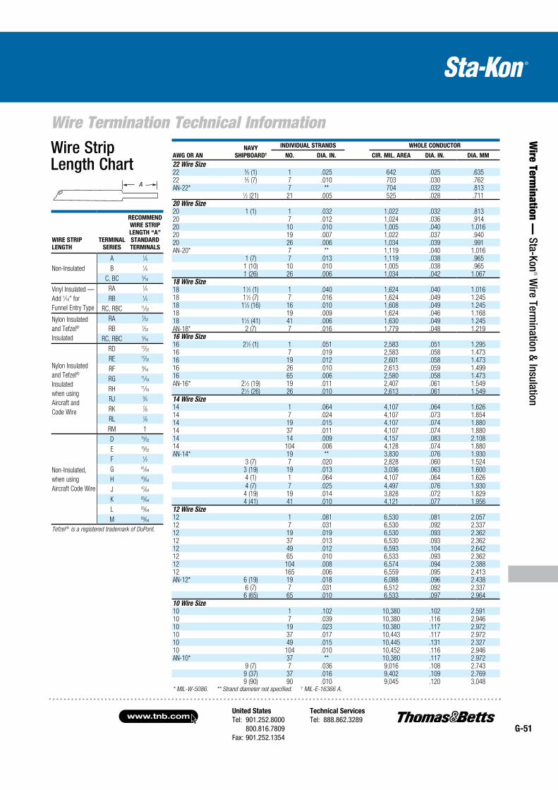
United States
Tel: 901.252.8000 800.816.7809Fax: 901.252.1354
Technical Services
Tel: 888.862.3289www.tnb.com
G-51
Wire Termination Technical Information
Wire Term
ination — Sta-Kon
® Wire Term
ination & Insulation
AWG OR AN
NAVY
SHIPBOARD†
INDIVIDUAL STRANDS WHOLE CONDUCTOR
NO. DIA. IN. CIR. MIL. AREA DIA. IN. DIA. MM
22 Wire Size22 3⁄5 (1) 1 .025 642 .025 .63522 3⁄5 (7) 7 .010 703 .030 .762AN-22* 7 ** 704 .032 .813
1⁄2 (21) 21 .005 525 .028 .71120 Wire Size20 1 (1) 1 .032 1,022 .032 .81320 7 .012 1,024 .036 .91420 10 .010 1,005 .040 1.01620 19 .007 1,022 .037 .94020 26 .006 1,034 .039 .991AN-20* 7 ** 1,119 .040 1.016
1 (7) 7 .013 1,119 .038 .9651 (10) 10 .010 1,005 .038 .9651 (26) 26 .006 1,034 .042 1.067
18 Wire Size18 11⁄2 (1) 1 .040 1,624 .040 1.01618 11⁄2 (7) 7 .016 1,624 .049 1.24518 11⁄2 (16) 16 .010 1,608 .049 1.24518 19 .009 1,624 .046 1.16818 11⁄2 (41) 41 .006 1,630 .049 1.245AN-18* 2 (7) 7 .016 1,779 .048 1.21916 Wire Size16 21⁄2 (1) 1 .051 2,583 .051 1.29516 7 .019 2,583 .058 1.47316 19 .012 2,601 .058 1.47316 26 .010 2,613 .059 1.49916 65 .006 2,580 .058 1.473AN-16* 21⁄2 (19) 19 .011 2,407 .061 1.549
21⁄2 (26) 26 .010 2,613 .061 1.54914 Wire Size14 1 .064 4,107 .064 1.62614 7 .024 4,107 .073 1.85414 19 .015 4,107 .074 1.88014 37 .011 4,107 .074 1.88014 14 .009 4,157 .083 2.10814 104 .006 4,128 .074 1.880AN-14* 19 ** 3,830 .076 1.930
3 (7) 7 .020 2,828 .060 1.5243 (19) 19 .013 3,036 .063 1.6004 (1) 1 .064 4,107 .064 1.626
4 (7) 7 .025 4,497 .076 1.9304 (19) 19 .014 3,828 .072 1.8294 (41) 41 .010 4,121 .077 1.956
12 Wire Size12 1 .081 6,530 .081 2.05712 7 .031 6,530 .092 2.33712 19 .019 6,530 .093 2.36212 37 .013 6,530 .093 2.36212 49 .012 6,593 .104 2.64212 65 .010 6,533 .093 2.36212 104 .008 6,574 .094 2.38812 165 .006 6,559 .095 2.413AN-12* 6 (19) 19 .018 6,088 .096 2.438
6 (7) 7 .031 6,512 .092 2.3376 (65) 65 .010 6,533 .097 2.964
10 Wire Size10 1 .102 10,380 .102 2.59110 7 .039 10,380 .116 2.94610 19 .023 10.380 .117 2.97210 37 .017 10,443 .117 2.97210 49 .015 10,445 .131 2.32710 104 .010 10,452 .116 2.946AN-10* 37 ** 10,380 .117 2.972
9 (7) 7 .036 9,016 .108 2.7439 (37) 37 .016 9,402 .109 2.7699 (90) 90 .010 9,045 .120 3.048
* MIL-W-5086. ** Strand diameter not specified. † MIL-E-16366 A.
WIRE STRIP
LENGTH
TERMINAL
SERIES
RECOMMEND
WIRE STRIP
LENGTH “A”
STANDARD
TERMINALS
Non-Insulated
A 1⁄4
B 1⁄4
C, BC 5⁄16
Vinyl Insulated —
Add 1⁄16" for
Funnel Entry Type
RA 1⁄4
RB 1⁄4
RC, RBC 11⁄32
Nylon Insulated
and Tefzel®
Insulated
RA 7⁄32
RB 7⁄32
RC, RBC 5⁄16
Nylon Insulated
and Tefzel®
Insulated
when using
Aircraft and
Code Wire
RD 17⁄32
RE 17⁄32
RF 9⁄16
RG 11⁄16
RH 11⁄16
RJ 3⁄4
RK 7⁄8
RL 7⁄8
RM 1
Non-Insulated,
when using
Aircraft Code Wire
D 15⁄32
E 15⁄32
F 1⁄2
G 41⁄64
H 43⁄64
J 47⁄64
K 55⁄64
L 55⁄64
M 59⁄64
Tefzel ® is a registered trademark of DuPont.
A
Wire Strip Length Chart
A
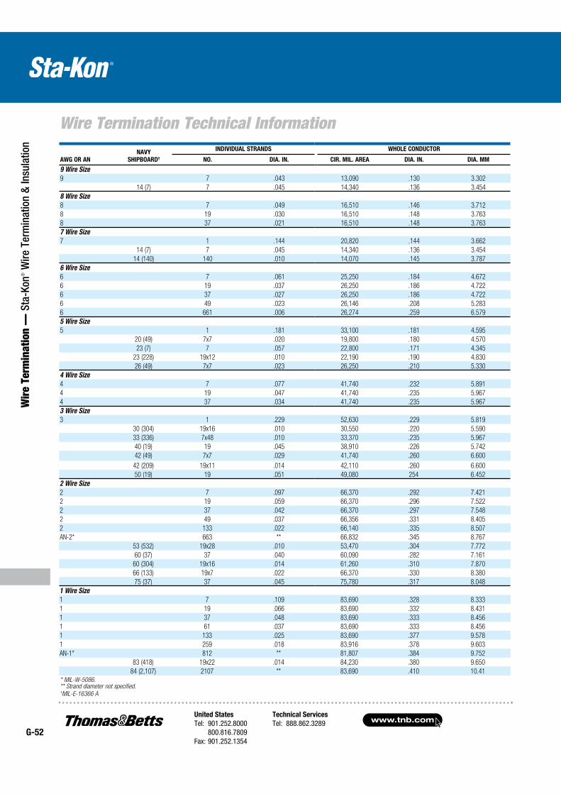
www.tnb.comUnited States
Tel: 901.252.8000 800.816.7809Fax: 901.252.1354
Technical Services
Tel: 888.862.3289G-52
Wire Termination Technical Information
Wir
e Te
rmin
atio
n —
Sta
-Kon
® W
ire T
erm
inat
ion
& In
sula
tion
AWG OR AN
NAVY
SHIPBOARD†
INDIVIDUAL STRANDS WHOLE CONDUCTOR
NO. DIA. IN. CIR. MIL. AREA DIA. IN. DIA. MM
9 Wire Size
9 7 .043 13,090 .130 3.302
14 (7) 7 .045 14,340 .136 3.454
8 Wire Size
8 7 .049 16,510 .146 3.712
8 19 .030 16,510 .148 3.763
8 37 .021 16,510 .148 3.763
7 Wire Size
7 1 .144 20,820 .144 3.662
14 (7) 7 .045 14,340 .136 3.454
14 (140) 140 .010 14,070 .145 3.787
6 Wire Size
6 7 .061 25,250 .184 4.672
6 19 .037 26,250 .186 4.722
6 37 .027 26,250 .186 4.722
6 49 .023 26,146 .208 5.283
6 661 .006 26,274 .259 6.579
5 Wire Size
5 1 .181 33,100 .181 4.595
20 (49) 7x7 .020 19,800 .180 4.570
23 (7) 7 .057 22,800 .171 4.345
23 (228) 19x12 .010 22,190 .190 4.830
26 (49) 7x7 .023 26,250 .210 5.330
4 Wire Size
4 7 .077 41,740 .232 5.891
4 19 .047 41,740 .235 5.967
4 37 .034 41,740 .235 5.967
3 Wire Size
3 1 .229 52,630 .229 5.819
30 (304) 19x16 .010 30,550 .220 5.590
33 (336) 7x48 .010 33,370 .235 5.967
40 (19) 19 .045 38,910 .226 5.742
42 (49) 7x7 .029 41,740 .260 6.600
42 (209) 19x11 .014 42,110 .260 6.600
50 (19) 19 .051 49,080 254 6.452
2 Wire Size
2 7 .097 66,370 .292 7.421
2 19 .059 66,370 .296 7.522
2 37 .042 66,370 .297 7.548
2 49 .037 66,356 .331 8.405
2 133 .022 66,140 .335 8.507
AN-2* 663 ** 66,832 .345 8.767
53 (532) 19x28 .010 53,470 .304 7.772
60 (37) 37 .040 60,090 .282 7.161
60 (304) 19x16 .014 61,260 .310 7.870
66 (133) 19x7 .022 66,370 .330 8.380
75 (37) 37 .045 75,780 .317 8.048
1 Wire Size
1 7 .109 83,690 .328 8.333
1 19 .066 83,690 .332 8.431
1 37 .048 83,690 .333 8.456
1 61 .037 83,690 .333 8.456
1 133 .025 83,690 .377 9.578
1 259 .018 83,916 .378 9.603
AN-1* 812 ** 81,807 .384 9.752
83 (418) 19x22 .014 84,230 .380 9.650
84 (2,107) 2107 ** 83,690 .410 10.41* MIL-W-5086. ** Strand diameter not specified. †MIL-E-16366 A
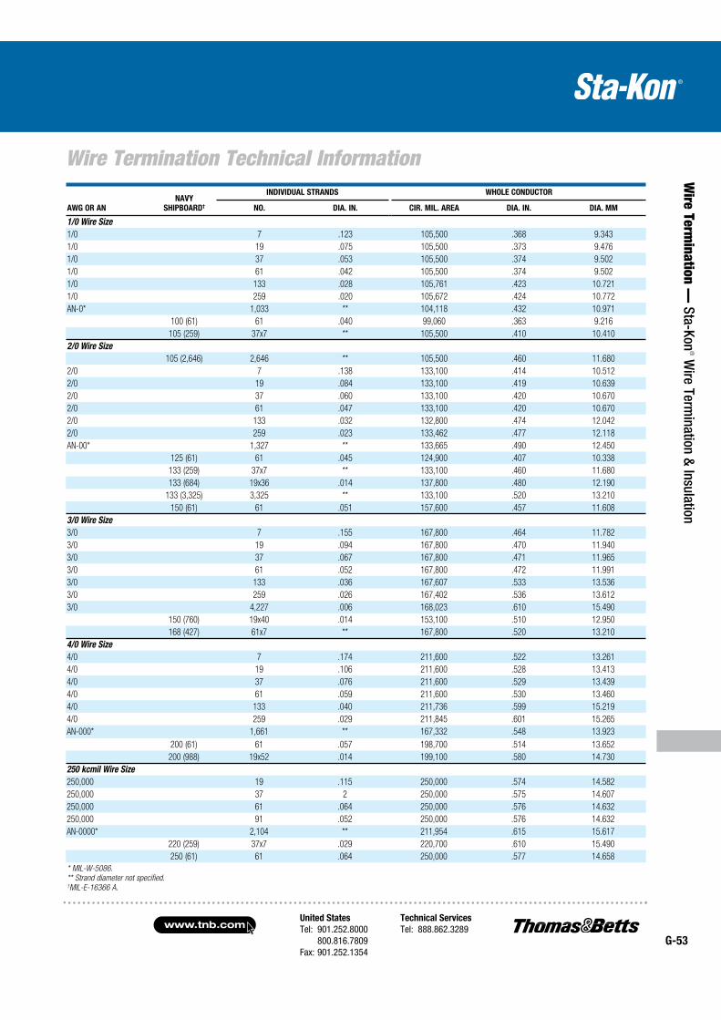
United States
Tel: 901.252.8000 800.816.7809Fax: 901.252.1354
Technical Services
Tel: 888.862.3289www.tnb.com
G-53
Wire Termination Technical Information
Wire Term
ination — Sta-Kon
® Wire Term
ination & Insulation
AWG OR AN
NAVY
SHIPBOARD†
INDIVIDUAL STRANDS WHOLE CONDUCTOR
NO. DIA. IN. CIR. MIL. AREA DIA. IN. DIA. MM
1/0 Wire Size
1/0 7 .123 105,500 .368 9.343
1/0 19 .075 105,500 .373 9.476
1/0 37 .053 105,500 .374 9.502
1/0 61 .042 105,500 .374 9.502
1/0 133 .028 105,761 .423 10.721
1/0 259 .020 105,672 .424 10.772
AN-0* 1,033 ** 104,118 .432 10.971
100 (61) 61 .040 99,060 .363 9.216
105 (259) 37x7 ** 105,500 .410 10.410
2/0 Wire Size
105 (2,646) 2,646 ** 105,500 .460 11.680
2/0 7 .138 133,100 .414 10.512
2/0 19 .084 133,100 .419 10.639
2/0 37 .060 133,100 .420 10.670
2/0 61 .047 133,100 .420 10.670
2/0 133 .032 132,800 .474 12.042
2/0 259 .023 133,462 .477 12.118
AN-00* 1,327 ** 133,665 .490 12.450
125 (61) 61 .045 124,900 .407 10.338
133 (259) 37x7 ** 133,100 .460 11.680
133 (684) 19x36 .014 137,800 .480 12.190
133 (3,325) 3,325 ** 133,100 .520 13.210
150 (61) 61 .051 157,600 .457 11.608
3/0 Wire Size
3/0 7 .155 167,800 .464 11.782
3/0 19 .094 167,800 .470 11.940
3/0 37 .067 167,800 .471 11.965
3/0 61 .052 167,800 .472 11.991
3/0 133 .036 167,607 .533 13.536
3/0 259 .026 167,402 .536 13.612
3/0 4,227 .006 168,023 .610 15.490
150 (760) 19x40 .014 153,100 .510 12.950
168 (427) 61x7 ** 167,800 .520 13.210
4/0 Wire Size
4/0 7 .174 211,600 .522 13.261
4/0 19 .106 211,600 .528 13.413
4/0 37 .076 211,600 .529 13.439
4/0 61 .059 211,600 .530 13.460
4/0 133 .040 211,736 .599 15.219
4/0 259 .029 211,845 .601 15.265
AN-000* 1,661 ** 167,332 .548 13.923
200 (61) 61 .057 198,700 .514 13.652
200 (988) 19x52 .014 199,100 .580 14.730
250 kcmil Wire Size
250,000 19 .115 250,000 .574 14.582
250,000 37 2 250,000 .575 14.607
250,000 61 .064 250,000 .576 14.632
250,000 91 .052 250,000 .576 14.632
AN-0000* 2,104 ** 211,954 .615 15.617
220 (259) 37x7 .029 220,700 .610 15.490
250 (61) 61 .064 250,000 .577 14.658
* MIL-W-5086.
** Strand diameter not specified. †MIL-E-16366 A.
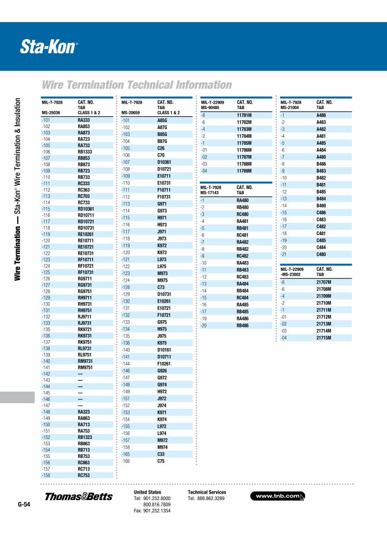
www.tnb.comUnited States
Tel: 901.252.8000 800.816.7809Fax: 901.252.1354
Technical Services
Tel: 888.862.3289G-54
Wire Termination Technical Information
Wir
e Te
rmin
atio
n —
Sta
-Kon
® W
ire T
erm
inat
ion
& In
sula
tion
MIL-T-7928
MS-25036
CAT. NO. T&B
CLASS 1 & 2
-101 RA333
-102 RA853
-103 RA873
-104 RA723
-105 RA733
-106 RB1333
-107 RB853
-108 RB873
-109 RB723
-110 RB733
-111 RC333
-112 RC363
-113 RC703
-114 RC733
-115 RD10361
-116 RD10711
-117 RD10721
-118 RD10731
-119 RE10261
-120 RE10711
-121 RE10721
-122 RE10731
-123 RF10711
-124 RF10721
-125 RF10731
-126 RG9711
-127 RG9731
-128 RG9751
-129 RH9711
-130 RH9731
-131 RH9751
-132 RJ9711
-133 RJ9731
-135 RK9721
-136 RK9731
-137 RK9751
-138 RL9731
-139 RL9751
-140 RM9731
-141 RM9751
-142 —
-143 —
-144 —
-145 —
-146 —
-147 —
-148 RA323
-149 RA863
-150 RA713
-151 RA753
-152 RB1323
-153 RB863
-154 RB713
-155 RB753
-156 RC863
-157 RC713
-158 RC753
MIL-T-7928
MS-20659
CAT. NO. T&B
CLASS 1 & 2
-101 A85G
-102 A87G
-103 B85G
-104 B87G
-105 C26
-106 C70
-107 D10361
-108 D10721
-109 E10711
-110 E10731
-111 F10711
-112 F10731
-113 G971
-114 G973
-115 H971
-116 H973
-117 J971
-118 J973
-119 K972
-120 K973
-121 L973
-122 L975
-123 M973
-124 M975
-128 C73
-129 D10731
-130 E10261
-131 E10721
-132 F10721
-133 G975
-134 H975
-135 J975
-136 K975
-140 D10161
-141 D10711
-144 F10261
-146 G926
-147 G972
-148 G974
-149 H972
-151 J972
-152 J974
-153 K971
-154 K974
-155 L972
-156 L974
-157 M972
-158 M974
-165 C33
-166 C75
MIL-T-7928
MS-21004
CAT. NO.T&B
-1 A486
-2 A483
-3 A482
-4 A481
-5 A485
-6 A484
-7 A480
-8 B486
-9 B483
-10 B482
-11 B481
-12 B485
-13 B484
-14 B480
-15 C486
-16 C483
-17 C482
-18 C481
-19 C485
-20 C484
-21 C480
MIL-T-22909
-MS-23002
CAT. NO.T&B
-8 21707M
-6 21708M
-4 21709M
-2 21710M
-1 21711M
-01 21712M
-02 21713M
-03 21714M
-04 21715M
MIL-T-22909
MS-90485
CAT. NO.T&B
-8 11781M
-6 11782M
-4 11783M
-2 11784M
-1 11785M
-01 11786M
-02 11787M
-03 11788M
-04 11789M
MIL-T-7928
MS-17143
CAT. NO.T&B
-1 RA480
-2 RB480
-3 RC480
-4 RA481
-5 RB481
-6 RC481
-7 RA482
-8 RB482
-9 RC482
-10 RA483
-11 RB483
-12 RC483
-13 RA484
-14 RB484
-15 RC484
-16 RA485
-17 RB485
-19 RA486
-20 RB486
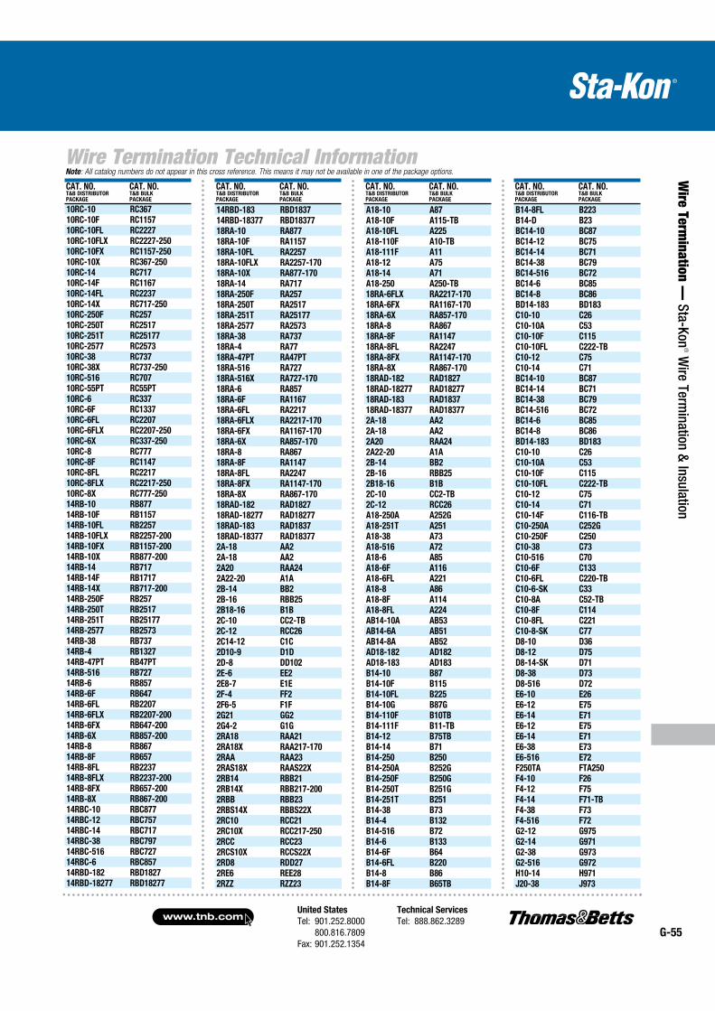
United States
Tel: 901.252.8000 800.816.7809Fax: 901.252.1354
Technical Services
Tel: 888.862.3289www.tnb.com
G-55
Wire Termination Technical Information
Wire Term
ination — Sta-Kon
® Wire Term
ination & Insulation
Note: All catalog numbers do not appear in this cross reference. This means it may not be available in one of the package options.
CAT. NO.T&B DISTRIBUTORPACKAGE
CAT. NO.T&B BULKPACKAGE
10RC-10 RC367
10RC-10F RC1157
10RC-10FL RC2227
10RC-10FLX RC2227-250
10RC-10FX RC1157-250
10RC-10X RC367-250
10RC-14 RC717
10RC-14F RC1167
10RC-14FL RC2237
10RC-14X RC717-250
10RC-250F RC257
10RC-250T RC2517
10RC-251T RC25177
10RC-2577 RC2573
10RC-38 RC737
10RC-38X RC737-250
10RC-516 RC707
10RC-55PT RC55PT
10RC-6 RC337
10RC-6F RC1337
10RC-6FL RC2207
10RC-6FLX RC2207-250
10RC-6X RC337-250
10RC-8 RC777
10RC-8F RC1147
10RC-8FL RC2217
10RC-8FLX RC2217-250
10RC-8X RC777-250
14RB-10 RB877
14RB-10F RB1157
14RB-10FL RB2257
14RB-10FLX RB2257-200
14RB-10FX RB1157-200
14RB-10X RB877-200
14RB-14 RB717
14RB-14F RB1717
14RB-14X RB717-200
14RB-250F RB257
14RB-250T RB2517
14RB-251T RB25177
14RB-2577 RB2573
14RB-38 RB737
14RB-4 RB1327
14RB-47PT RB47PT
14RB-516 RB727
14RB-6 RB857
14RB-6F RB647
14RB-6FL RB2207
14RB-6FLX RB2207-200
14RB-6FX RB647-200
14RB-6X RB857-200
14RB-8 RB867
14RB-8F RB657
14RB-8FL RB2237
14RB-8FLX RB2237-200
14RB-8FX RB657-200
14RB-8X RB867-200
14RBC-10 RBC877
14RBC-12 RBC757
14RBC-14 RBC717
14RBC-38 RBC797
14RBC-516 RBC727
14RBC-6 RBC857
14RBD-182 RBD1827
14RBD-18277 RBD18277
CAT. NO.T&B DISTRIBUTORPACKAGE
CAT. NO.T&B BULKPACKAGE
14RBD-183 RBD1837
14RBD-18377 RBD18377
18RA-10 RA877
18RA-10F RA1157
18RA-10FL RA2257
18RA-10FLX RA2257-170
18RA-10X RA877-170
18RA-14 RA717
18RA-250F RA257
18RA-250T RA2517
18RA-251T RA25177
18RA-2577 RA2573
18RA-38 RA737
18RA-4 RA77
18RA-47PT RA47PT
18RA-516 RA727
18RA-516X RA727-170
18RA-6 RA857
18RA-6F RA1167
18RA-6FL RA2217
18RA-6FLX RA2217-170
18RA-6FX RA1167-170
18RA-6X RA857-170
18RA-8 RA867
18RA-8F RA1147
18RA-8FL RA2247
18RA-8FX RA1147-170
18RA-8X RA867-170
18RAD-182 RAD1827
18RAD-18277 RAD18277
18RAD-183 RAD1837
18RAD-18377 RAD18377
2A-18 AA2
2A-18 AA2
2A20 RAA24
2A22-20 A1A
2B-14 BB2
2B-16 RBB25
2B18-16 B1B
2C-10 CC2-TB
2C-12 RCC26
2C14-12 C1C
2D10-9 D1D
2D-8 DD102
2E-6 EE2
2E8-7 E1E
2F-4 FF2
2F6-5 F1F
2G21 GG2
2G4-2 G1G
2RA18 RAA21
2RA18X RAA217-170
2RAA RAA23
2RAS18X RAAS22X
2RB14 RBB21
2RB14X RBB217-200
2RBB RBB23
2RBS14X RBBS22X
2RC10 RCC21
2RC10X RCC217-250
2RCC RCC23
2RCS10X RCCS22X
2RD8 RDD27
2RE6 REE28
2RZZ RZZ23
CAT. NO.T&B DISTRIBUTORPACKAGE
CAT. NO.T&B BULKPACKAGE
A18-10 A87
A18-10F A115-TB
A18-10FL A225
A18-110F A10-TB
A18-111F A11
A18-12 A75
A18-14 A71
A18-250 A250-TB
18RA-6FLX RA2217-170
18RA-6FX RA1167-170
18RA-6X RA857-170
18RA-8 RA867
18RA-8F RA1147
18RA-8FL RA2247
18RA-8FX RA1147-170
18RA-8X RA867-170
18RAD-182 RAD1827
18RAD-18277 RAD18277
18RAD-183 RAD1837
18RAD-18377 RAD18377
2A-18 AA2
2A-18 AA2
2A20 RAA24
2A22-20 A1A
2B-14 BB2
2B-16 RBB25
2B18-16 B1B
2C-10 CC2-TB
2C-12 RCC26
A18-250A A252G
A18-251T A251
A18-38 A73
A18-516 A72
A18-6 A85
A18-6F A116
A18-6FL A221
A18-8 A86
A18-8F A114
A18-8FL A224
AB14-10A AB53
AB14-6A AB51
AB14-8A AB52
AD18-182 AD182
AD18-183 AD183
B14-10 B87
B14-10F B115
B14-10FL B225
B14-10G B87G
B14-110F B10TB
B14-111F B11-TB
B14-12 B75TB
B14-14 B71
B14-250 B250
B14-250A B252G
B14-250F B250G
B14-250T B251G
B14-251T B251
B14-38 B73
B14-4 B132
B14-516 B72
B14-6 B133
B14-6F B64
B14-6FL B220
B14-8 B86
B14-8F B65TB
CAT. NO.T&B DISTRIBUTORPACKAGE
CAT. NO.T&B BULKPACKAGE
B14-8FL B223
B14-D B23
BC14-10 BC87
BC14-12 BC75
BC14-14 BC71
BC14-38 BC79
BC14-516 BC72
BC14-6 BC85
BC14-8 BC86
BD14-183 BD183
C10-10 C26
C10-10A C53
C10-10F C115
C10-10FL C222-TB
C10-12 C75
C10-14 C71
BC14-10 BC87
BC14-14 BC71
BC14-38 BC79
BC14-516 BC72
BC14-6 BC85
BC14-8 BC86
BD14-183 BD183
C10-10 C26
C10-10A C53
C10-10F C115
C10-10FL C222-TB
C10-12 C75
C10-14 C71
C10-14F C116-TB
C10-250A C252G
C10-250F C250
C10-38 C73
C10-516 C70
C10-6F C133
C10-6FL C220-TB
C10-6-SK C33
C10-8A C52-TB
C10-8F C114
C10-8FL C221
C10-8-SK C77
D8-10 D36
D8-12 D75
D8-14-SK D71
D8-38 D73
D8-516 D72
E6-10 E26
E6-12 E75
E6-14 E71
E6-12 E75
E6-14 E71
E6-38 E73
E6-516 E72
F250TA FTA250
F4-10 F26
F4-12 F75
F4-14 F71-TB
F4-38 F73
F4-516 F72
G2-12 G975
G2-14 G971
G2-38 G973
G2-516 G972
H10-14 H971
J20-38 J973
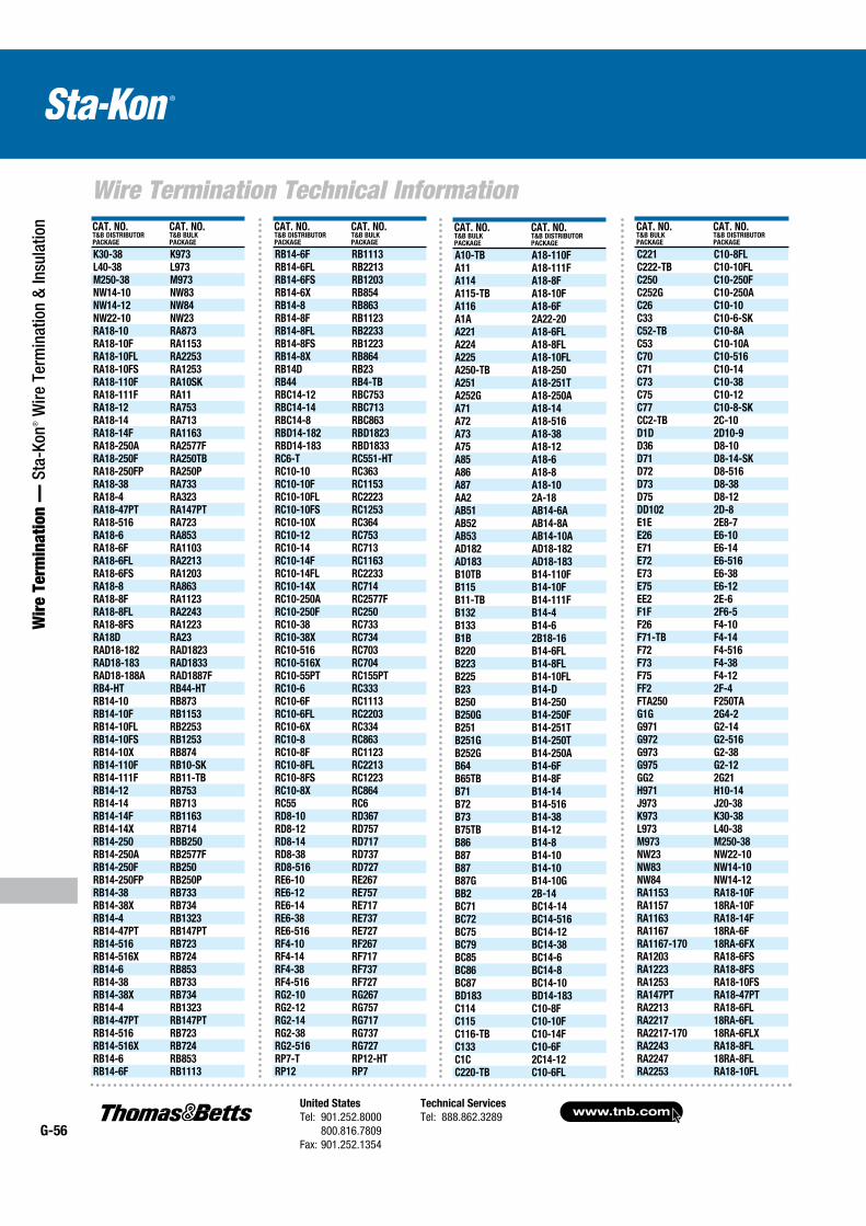
www.tnb.comUnited States
Tel: 901.252.8000 800.816.7809Fax: 901.252.1354
Technical Services
Tel: 888.862.3289G-56
Wire Termination Technical Information
Wir
e Te
rmin
atio
n —
Sta
-Kon
® W
ire T
erm
inat
ion
& In
sula
tion CAT. NO.
T&B DISTRIBUTORPACKAGE
CAT. NO.T&B BULKPACKAGE
K30-38 K973
L40-38 L973
M250-38 M973
NW14-10 NW83
NW14-12 NW84
NW22-10 NW23
RA18-10 RA873
RA18-10F RA1153
RA18-10FL RA2253
RA18-10FS RA1253
RA18-110F RA10SK
RA18-111F RA11
RA18-12 RA753
RA18-14 RA713
RA18-14F RA1163
RA18-250A RA2577F
RA18-250F RA250TB
RA18-250FP RA250P
RA18-38 RA733
RA18-4 RA323
RA18-47PT RA147PT
RA18-516 RA723
RA18-6 RA853
RA18-6F RA1103
RA18-6FL RA2213
RA18-6FS RA1203
RA18-8 RA863
RA18-8F RA1123
RA18-8FL RA2243
RA18-8FS RA1223
RA18D RA23
RAD18-182 RAD1823
RAD18-183 RAD1833
RAD18-188A RAD1887F
RB4-HT RB44-HT
RB14-10 RB873
RB14-10F RB1153
RB14-10FL RB2253
RB14-10FS RB1253
RB14-10X RB874
RB14-110F RB10-SK
RB14-111F RB11-TB
RB14-12 RB753
RB14-14 RB713
RB14-14F RB1163
RB14-14X RB714
RB14-250 RBB250
RB14-250A RB2577F
RB14-250F RB250
RB14-250FP RB250P
RB14-38 RB733
RB14-38X RB734
RB14-4 RB1323
RB14-47PT RB147PT
RB14-516 RB723
RB14-516X RB724
RB14-6 RB853
RB14-38 RB733
RB14-38X RB734
RB14-4 RB1323
RB14-47PT RB147PT
RB14-516 RB723
RB14-516X RB724
RB14-6 RB853
RB14-6F RB1113
CAT. NO.T&B DISTRIBUTORPACKAGE
CAT. NO.T&B BULKPACKAGE
RB14-6F RB1113
RB14-6FL RB2213
RB14-6FS RB1203
RB14-6X RB854
RB14-8 RB863
RB14-8F RB1123
RB14-8FL RB2233
RB14-8FS RB1223
RB14-8X RB864
RB14D RB23
RB44 RB4-TB
RBC14-12 RBC753
RBC14-14 RBC713
RBC14-8 RBC863
RBD14-182 RBD1823
RBD14-183 RBD1833
RC6-T RC551-HT
RC10-10 RC363
RC10-10F RC1153
RC10-10FL RC2223
RC10-10FS RC1253
RC10-10X RC364
RC10-12 RC753
RC10-14 RC713
RC10-14F RC1163
RC10-14FL RC2233
RC10-14X RC714
RC10-250A RC2577F
RC10-250F RC250
RC10-38 RC733
RC10-38X RC734
RC10-516 RC703
RC10-516X RC704
RC10-55PT RC155PT
RC10-6 RC333
RC10-6F RC1113
RC10-6FL RC2203
RC10-6X RC334
RC10-8 RC863
RC10-8F RC1123
RC10-8FL RC2213
RC10-8FS RC1223
RC10-8X RC864
RC55 RC6
RD8-10 RD367
RD8-12 RD757
RD8-14 RD717
RD8-38 RD737
RD8-516 RD727
RE6-10 RE267
RE6-12 RE757
RE6-14 RE717
RE6-38 RE737
RE6-516 RE727
RF4-10 RF267
RF4-14 RF717
RF4-38 RF737
RF4-516 RF727
RG2-10 RG267
RG2-12 RG757
RG2-14 RG717
RG2-38 RG737
RG2-516 RG727
RP7-T RP12-HT
RP12 RP7
CAT. NO.T&B BULKPACKAGE
CAT. NO.T&B DISTRIBUTORPACKAGE
C221 C10-8FL
C222-TB C10-10FL
C250 C10-250F
C252G C10-250A
C26 C10-10
C33 C10-6-SK
C52-TB C10-8A
C53 C10-10A
C70 C10-516
C71 C10-14
C73 C10-38
C75 C10-12
C77 C10-8-SK
CC2-TB 2C-10
D1D 2D10-9
D36 D8-10
D71 D8-14-SK
D72 D8-516
D73 D8-38
D75 D8-12
DD102 2D-8
E1E 2E8-7
E26 E6-10
E71 E6-14
E72 E6-516
E73 E6-38
E75 E6-12
EE2 2E-6
F1F 2F6-5
F26 F4-10
F71-TB F4-14
F72 F4-516
F73 F4-38
F75 F4-12
FF2 2F-4
FTA250 F250TA
G1G 2G4-2
G971 G2-14
G972 G2-516
G973 G2-38
G975 G2-12
GG2 2G21
H971 H10-14
J973 J20-38
K973 K30-38
L973 L40-38
M973 M250-38
NW23 NW22-10
NW83 NW14-10
NW84 NW14-12
RA1153 RA18-10F
RA1157 18RA-10F
RA1163 RA18-14F
RA1167 18RA-6F
RA1167-170 18RA-6FX
RA1203 RA18-6FS
RA1223 RA18-8FS
RA1253 RA18-10FS
RA147PT RA18-47PT
RA2213 RA18-6FL
RA2217 18RA-6FL
RA2217-170 18RA-6FLX
RA2243 RA18-8FL
RA2247 18RA-8FL
RA2253 RA18-10FL
CAT. NO.T&B BULKPACKAGE
CAT. NO.T&B DISTRIBUTORPACKAGE
A10-TB A18-110F
A11 A18-111F
A114 A18-8F
A115-TB A18-10F
A116 A18-6F
A1A 2A22-20
A221 A18-6FL
A224 A18-8FL
A225 A18-10FL
A250-TB A18-250
A251 A18-251T
A252G A18-250A
A71 A18-14
A72 A18-516
A73 A18-38
A75 A18-12
A85 A18-6
A86 A18-8
A87 A18-10
AA2 2A-18
AB51 AB14-6A
AB52 AB14-8A
AB53 AB14-10A
AD182 AD18-182
AD183 AD18-183
B10TB B14-110F
B115 B14-10F
B11-TB B14-111F
B132 B14-4
B133 B14-6
B1B 2B18-16
B220 B14-6FL
B223 B14-8FL
B225 B14-10FL
B23 B14-D
B250 B14-250
B250G B14-250F
B251 B14-251T
B251G B14-250T
B252G B14-250A
B64 B14-6F
B65TB B14-8F
B71 B14-14
B72 B14-516
B73 B14-38
B75TB B14-12
B86 B14-8
B87 B14-10
B87 B14-10
B87G B14-10G
BB2 2B-14
BC71 BC14-14
BC72 BC14-516
BC75 BC14-12
BC79 BC14-38
BC85 BC14-6
BC86 BC14-8
BC87 BC14-10
BD183 BD14-183
C114 C10-8F
C115 C10-10F
C116-TB C10-14F
C133 C10-6F
C1C 2C14-12
C220-TB C10-6FL
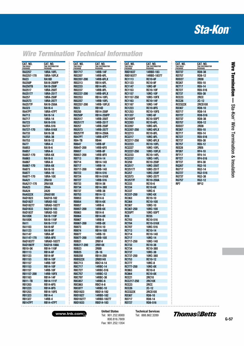
United States
Tel: 901.252.8000 800.816.7809Fax: 901.252.1354
Technical Services
Tel: 888.862.3289www.tnb.com
G-57
Wire Termination Technical Information
Wire Term
ination — Sta-Kon
® Wire Term
ination & Insulation
CAT. NO.T&B BULKPACKAGE
CAT. NO.T&B DISTRIBUTORPACKAGE
RA2257 18RA-10FL
RA2257-170 18RA-10FLX
RA23 RA18D
RA250P RA18-250FP
RA250TB RA18-250F
RA2517 18RA-250T
RA25177 18RA-251T
RA257 18RA-250F
RA2573 18RA-2577
RA2577F RA18-250A
RA323 RA18-4
RA47PT 18RA-47PT
RA713 RA18-14
RA717 18RA-14
RA723 RA18-516
RA727 18RA-516
RA727-170 18RA-516X
RA733 RA18-38
RA737 18RA-38
RA753 RA18-12
RA77 18RA-4
RA853 RA18-6
RA857 18RA-6
RA857-170 18RA-6X
RA863 RA18-8
RA867 18RA-8
RA867-170 18RA-8X
RA873 RA18-10
RA877 18RA-10
RA877-170 18RA-10X
RAA21 2RA18
RAA217-170 2RA18X
RAA23 2RAA
RAA24 2A20
RAAS22X 2RAS18X
RAD1823 RAD18-182
RAD1827 18RAD-182
RAD18277 18RAD-18277
RAD1833 RAD18-183
RAD1837 18RAD-183
RA10SK RA18-110F
RA10SK RA18-110F
RA11 RA18-111F
RA1103 RA18-6F
RA1123 RA18-8F
RA1147 18RA-8F
RA1147-170 18RA-8FX
RAD18377 18RAD-18377
RAD1887F RAD18-188A
RB10-SK RB14-110F
RB1113 RB14-6F
RB1123 RB14-8F
RB1153 RB14-10F
RB1157 14RB-10F
RB1153 RB14-10F
RB1157 14RB-10F
RB1157-200 14RB-10FX
RB1163 RB14-14F
RB11-TB RB14-111F
RB1203 RB14-6FS
RB1223 RB14-8FS
RB1253 RB14-10FS
RB1323 RB14-4
RB1327 14RB-4
RB147PT RB14-47PT
CAT. NO.T&B BULKPACKAGE
CAT. NO.T&B DISTRIBUTORPACKAGE
RB1717 14RB-14F
RB2207 14RB-6FL
RB2207-200 14RB-6FLX
RB2213 RB14-6FL
RB2233 RB14-8FL
RB2237 14RB-8FL
RB2237-200 14RB-8FLX
RB2253 RB14-10FL
RB2257 14RB-10FL
RB2257-200 14RB-10FLX
RB23 RB14D
RB250 RB14-250F
RB250P RB14-250FP
RB2517 14RB-250T
RB25177 14RB-251T
RB257 14RB-250F
RB2573 14RB-2577
RB2577F RB14-250A
RB47PT 14RB-47PT
RB4-TB RB44
RB647 14RB-6F
RB647-200 14RB-6FX
RB657 14RB-8F
RB657-200 14RB-8FX
RB713 RB14-14
RB714 RB14-14X
RB717 14RB-14
RB717-200 14RB-14X
RB723 RB14-516
RB724 RB14-516X
RB727 14RB-516
RB733 RB14-38
RB734 RB14-38X
RB737 14RB-38
RB753 RB14-12
RB853 RB14-6
RB854 RB14-6X
RB857 14RB-6
RB857-200 14RB-6X
RB863 RB14-8
RB864 RB14-8X
RB867 14RB-8
RB867-200 14RB-8X
RB873 RB14-10
RB874 RB14-10X
RB877 14RB-10
RB877-200 14RB-10X
RBB21 2RB14
RBB217-200 2RB14X
RBB23 2RBB
RBB25 2B-16
RBB250 RB14-250
RBBS22X 2RBS14X
RBC713 RBC14-14
RBC717 14RBC-14
RBC727 14RBC-516
RBC757 14RBC-12
RBC797 14RBC-38
RBC857 14RBC-6
RBC863 RBC14-8
RBC877 14RBC-10
RBD1823 RBD14-182
RBD1827 14RBD-182
RBD18277 14RBD-18277
RBD1833 RBD14-183
CAT. NO.T&B BULKPACKAGE
CAT. NO.T&B DISTRIBUTORPACKAGE
RBD1837 14RBD-183
RBD18377 14RBD-18377
RC1113 RC10-6F
RC1123 RC10-8F
RC1147 10RC-8F
RC1153 RC10-10F
RC1157 10RC-10F
RC1157-250 10RC-10FX
RC1163 RC10-14F
RC1167 10RC-14F
RC1223 RC10-8FS
RC1253 RC10-10FS
RC1337 10RC-6F
RC155PT RC10-55PT
RC2203 RC10-6FL
RC2207 10RC-6FL
RC2207-250 10RC-6FLX
RC2213 RC10-8FL
RC2217 10RC-8FL
RC2217-250 10RC-8FLX
RC2223 RC10-10FL
RC2227 10RC-10FL
RC2227-250 10RC-10FLX
RC2233 RC10-14FL
RC2237 10RC-14FL
RC250 RC10-250F
RC2517 10RC-250T
RC25177 10RC-251T
RC257 10RC-250F
RC2573 10RC-2577
RC2577F RC10-250A
RC333 RC10-6
RC334 RC10-6X
RC337 10RC-6
RC337-250 10RC-6X
RC363 RC10-10
RC364 RC10-10X
RC367 10RC-10
RC367-250 10RC-10X
RC55PT 10RC-55PT
RC6 RC55
RC703 RC10-516
RC704 RC10-516X
RC707 10RC-516
RC713 RC10-14
RC714 RC10-14X
RC717 10RC-14
RC717-250 10RC-14X
RC733 RC10-38
RC734 RC10-38X
RC737 10RC-38
RC737-250 10RC-38X
RC753 RC10-12
RC777 10RC-8
RC777-250 10RC-8X
RC863 RC10-8
RC864 RC10-8X
RCC21 2RC10
RCC217-250 2RC10X
RCC23 2RCC
RCC26 2C-12
RCCS22X 2RCS10X
RD367 RD8-10
RD717 RD8-14
RD727 RD8-516
CAT. NO.T&B BULKPACKAGE
CAT. NO.T&B DISTRIBUTORPACKAGE
RD737 RD8-38
RD757 RD8-12
RDD27 2RD8
RE267 RE6-10
RE717 RE6-14
RE727 RE6-516
RE737 RE6-38
RCC23 2RCC
RCC26 2C-12
RCCS22X 2RCS10X
RD367 RD8-10
RD717 RD8-14
RD727 RD8-516
RD737 RD8-38
RD757 RD8-12
RDD27 2RD8
RE267 RE6-10
RE717 RE6-14
RE727 RE6-516
RE737 RE6-38
RE757 RE6-12
REE28 2RE6
RF267 RF4-10
RF717 RF4-14
RF727 RF4-516
RF737 RF4-38
RG267 RG2-10
RG717 RG2-14
RG727 RG2-516
RG737 RG2-38
RG757 RG2-12
RP7 RP12
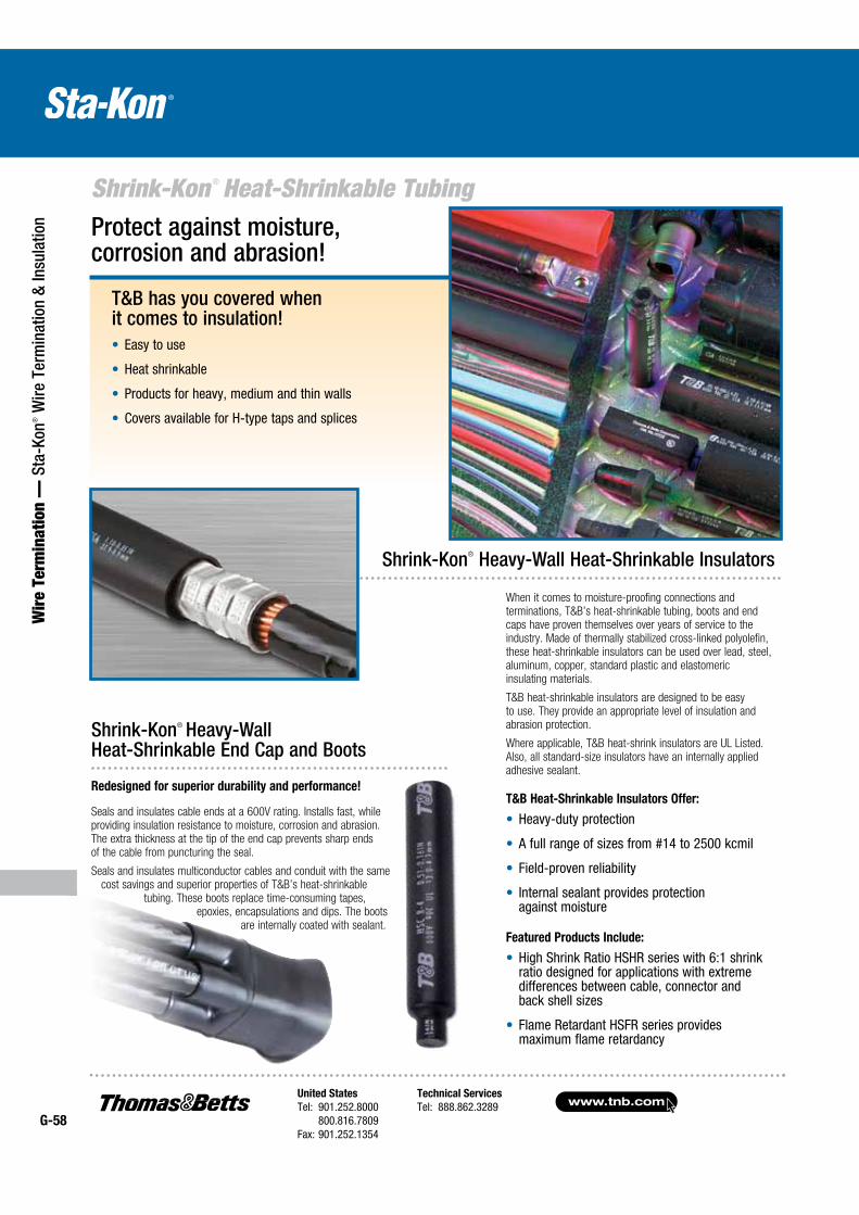
www.tnb.comUnited States
Tel: 901.252.8000 800.816.7809Fax: 901.252.1354
Technical Services
Tel: 888.862.3289G-58
Shrink-Kon ® Heat-Shrinkable Tubing
Wir
e Te
rmin
atio
n —
Sta
-Kon
® W
ire T
erm
inat
ion
& In
sula
tion
T&B has you covered when it comes to insulation!
Easy to use
Heat shrinkable
Products for heavy, medium and thin walls
Covers available for H-type taps and splices
Protect against moisture, corrosion and abrasion!
Shrink-Kon® Heavy-Wall Heat-Shrinkable Insulators
When it comes to moisture-proofing connections and terminations, T&B’s heat-shrinkable tubing, boots and end caps have proven themselves over years of service to the industry. Made of thermally stabilized cross-linked polyolefin, these heat-shrinkable insulators can be used over lead, steel, aluminum, copper, standard plastic and elastomeric insulating materials.
T&B heat-shrinkable insulators are designed to be easy to use. They provide an appropriate level of insulation and abrasion protection.
Where applicable, T&B heat-shrink insulators are UL Listed. Also, all standard-size insulators have an internally applied adhesive sealant.
T&B Heat-Shrinkable Insulators Offer:
Heavy-duty protection
A full range of sizes from #14 to 2500 kcmil
Field-proven reliability
Internal sealant provides protection against moisture
Featured Products Include:
High Shrink Ratio HSHR series with 6:1 shrink ratio designed for applications with extreme differences between cable, connector and back shell sizes
Flame Retardant HSFR series provides maximum flame retardancy
Shrink-Kon® Heavy-Wall Heat-Shrinkable End Cap and Boots
Redesigned for superior durability and performance!
Seals and insulates cable ends at a 600V rating. Installs fast, while providing insulation resistance to moisture, corrosion and abrasion. The extra thickness at the tip of the end cap prevents sharp ends of the cable from puncturing the seal.
Seals and insulates multi conductor cables and conduit with the same cost savings and superior properties of T&B’s heat-shrinkable
tubing. These boots replace time-consuming tapes, epoxies, encapsulations and dips. The boots
are internally coated with sealant.
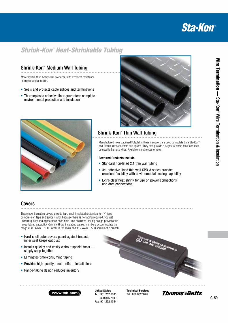
United States
Tel: 901.252.8000 800.816.7809Fax: 901.252.1354
Technical Services
Tel: 888.862.3289www.tnb.com
G-59
Shrink-Kon ® Heat-Shrinkable Tubing
Wire Term
ination — Sta-Kon
® Wire Term
ination & Insulation
These new insulating covers provide hard-shell insulated protection for “H” type compression taps and splices, and, because there is no taping required, you get uniform quality and appearance each time. The exclusive locking design provides the range-taking capability. Only six H-tap insulating catalog numbers accommodate the range of #6 AWG – 1000 kcmil in the main and #12 AWG – 500 kcmil in the branch.
Hard-shell outer covers guard against impact, inner seal keeps out dust
Installs quickly and easily without special tools — simply snap together
Eliminates time-consuming taping
Provides high-quality, neat, uniform installations
Range-taking design reduces inventory
Shrink-Kon® Medium Wall Tubing
More flexible than heavy-wall products, with excellent resistance to impact and abrasion.
Seals and protects cable splices and terminations
Thermoplastic adhesive liner guarantees complete environmental protection and insulation
Shrink-Kon® Thin Wall Tubing
Manufactured from stabilized Polyolefin, these insulators are used to insulate bare Sta-Kon®
and Blackburn® connectors and splices. They also provide a degree of strain relief and may be used to harness wires. Available in cut pieces or reels.
Featured Products Include:
Standard non-lined 2:1 thin wall tubing
3:1 adhesive-lined thin wall CPO-A series provides excellent flexibility with environmental sealing capability
Extra-clear heat shrink for use on power connections and data connections
Covers
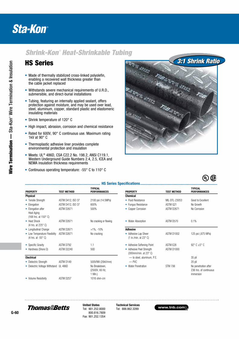
www.tnb.comUnited States
Tel: 901.252.8000 800.816.7809Fax: 901.252.1354
Technical Services
Tel: 888.862.3289G-60
Shrink-Kon ® Heat-Shrinkable Tubing
Wir
e Te
rmin
atio
n —
Sta
-Kon
® W
ire T
erm
inat
ion
& In
sula
tion HS Series
............................................................................... HS Series Specifications .................................................................................
Made of thermally stabilized cross-linked polyolefin, enabling a recovered wall thickness greater than the cable jacket replaced
Withstands severe mechanical requirements of U.R.D., submersible, and direct-burial installations
Tubing, featuring an internally applied sealant, offers protection against moisture, and may be used over lead, steel, aluminum, copper, standard plastic and elastomeric insulating materials
Shrink temperature of 120° C
High impact, abrasion, corrosion and chemical resistance
Rated for 600V, 90° C continuous use. Maximum rating 1kV at 90° C
Thermoplastic adhesive liner provides complete environmental protection and insulation
Meets: UL® 486D, CSA C22.2 No. 198.2, ANSI C119.1, Western Underground Guide Numbers 2.4, 2.5, ICEA and NEMA insulation thickness requirements
Continuous operating temperature: -55° C to 110° C
PROPERTY TEST METHOD
TYPICAL
PERFORMANCES PROPERTY TEST METHOD
TYPICAL
PERFORMANCES
Physical Chemical
Tensile Strength ASTM D412, ISO 37 2100 psi (14.5MPa) Fluid Resistance MIL-DTL-23053 Good to Excellent
Elongation ASTM D412, ISO 37 600% Fungus Resistance ASTM G21 No Growth
Elongation after
Heat Aging
(168 hrs. at 150° C)
ASTM D2671 500% Copper Corrosion ASTM D2671 No Corrosion
Heat Shock
(4 hrs. at 225° C)
ASTM D2671 No cracking or flowing Water Absorption ASTM D570 0.1%
Longitudinal Change ASTM D2671 +1%, -10% Adhesive
Low Temperature Flexibility
(4 hrs. at -55° C)
ASTM D2671 No cracking Adhesive Lap Sheer
(1 in./min. at 23° C)
ASTM D1002 125 psi (.875 MPa)
Specific Gravity ASTM D792 1.1 Adhesive Softening Point ASTM E28 92° C ±5° C
Hardness (Shore D) ASTM D2240 50D Adhesive Peel Strength
(300mm/min. at 23° C)
ASTM D1000
Electrical — to steel, aluminum, P.E. 35 pli
Dielectric Strength ASTM D149 500V/Mil (20kV/mm) — PVC 20 pli
Dielectric Voltage Withstand UL 486D No Breakdown,
(2500V, 60 Hz,
1 Min.)
Water Penetration STM 706 No penetration after
236 hrs. of continuous
immersion
Volume Resistivity ASTM D257 1016 ohm-cm
3:1 Shrink Ratio3:1 Shrink Ratio
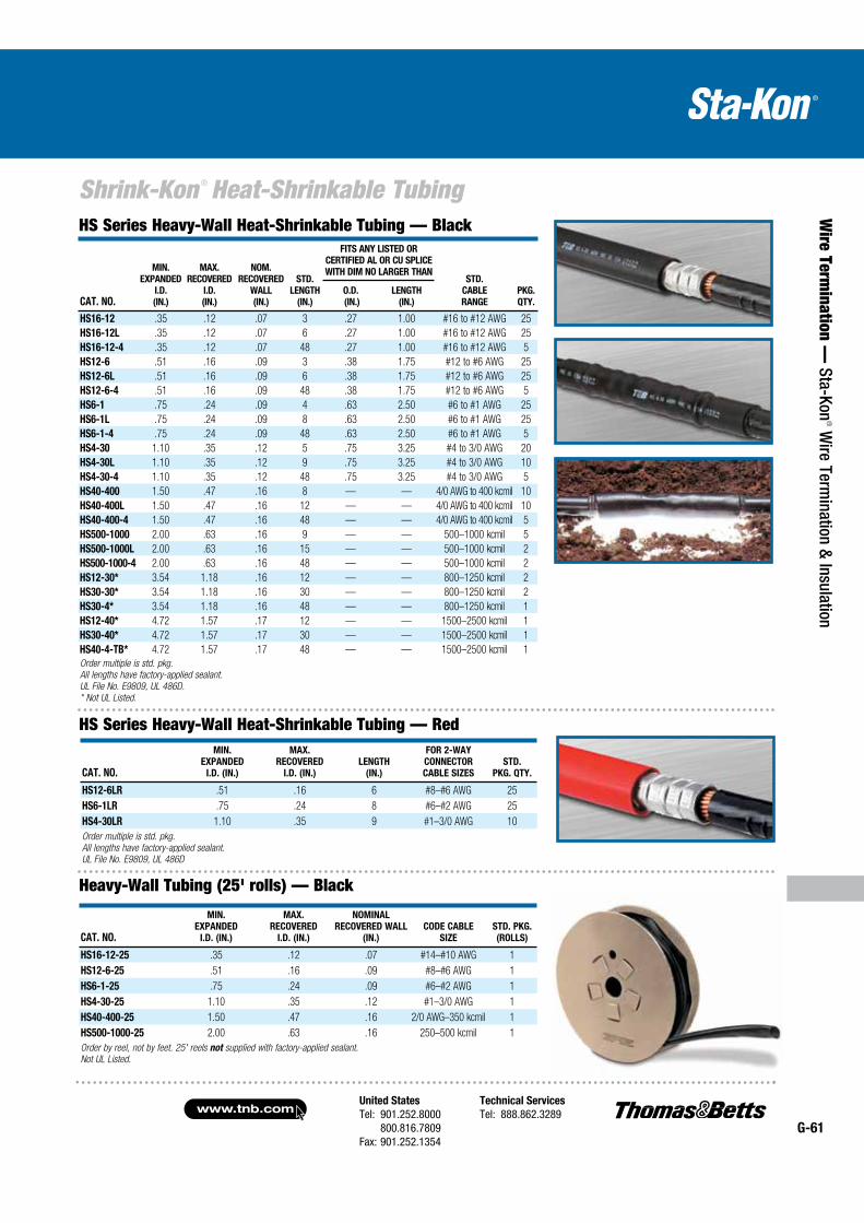
United States
Tel: 901.252.8000 800.816.7809Fax: 901.252.1354
Technical Services
Tel: 888.862.3289www.tnb.com
G-61
Shrink-Kon ® Heat-Shrinkable Tubing
Wire Term
ination — Sta-Kon
® Wire Term
ination & Insulation
CAT. NO.
MIN.
EXPANDED
I.D.
(IN.)
MAX.
RECOVERED
I.D.
(IN.)
NOM.
RECOVERED
WALL
(IN.)
STD.
LENGTH
(IN.)
FITS ANY LISTED OR
CERTIFIED AL OR CU SPLICE
WITH DIM NO LARGER THANSTD.
CABLE
RANGE
PKG.
QTY.
O.D.
(IN.)
LENGTH
(IN.)
HS16-12 .35 .12 .07 3 .27 1.00 #16 to #12 AWG 25
HS16-12L .35 .12 .07 6 .27 1.00 #16 to #12 AWG 25
HS16-12-4 .35 .12 .07 48 .27 1.00 #16 to #12 AWG 5
HS12-6 .51 .16 .09 3 .38 1.75 #12 to #6 AWG 25
HS12-6L .51 .16 .09 6 .38 1.75 #12 to #6 AWG 25
HS12-6-4 .51 .16 .09 48 .38 1.75 #12 to #6 AWG 5
HS6-1 .75 .24 .09 4 .63 2.50 #6 to #1 AWG 25
HS6-1L .75 .24 .09 8 .63 2.50 #6 to #1 AWG 25
HS6-1-4 .75 .24 .09 48 .63 2.50 #6 to #1 AWG 5
HS4-30 1.10 .35 .12 5 .75 3.25 #4 to 3/0 AWG 20
HS4-30L 1.10 .35 .12 9 .75 3.25 #4 to 3/0 AWG 10
HS4-30-4 1.10 .35 .12 48 .75 3.25 #4 to 3/0 AWG 5
HS40-400 1.50 .47 .16 8 — — 4/0 AWG to 400 kcmil 10
HS40-400L 1.50 .47 .16 12 — — 4/0 AWG to 400 kcmil 10
HS40-400-4 1.50 .47 .16 48 — — 4/0 AWG to 400 kcmil 5
HS500-1000 2.00 .63 .16 9 — — 500–1000 kcmil 5
HS500-1000L 2.00 .63 .16 15 — — 500–1000 kcmil 2
HS500-1000-4 2.00 .63 .16 48 — — 500–1000 kcmil 2
HS12-30* 3.54 1.18 .16 12 — — 800–1250 kcmil 2
HS30-30* 3.54 1.18 .16 30 — — 800–1250 kcmil 2
HS30-4* 3.54 1.18 .16 48 — — 800–1250 kcmil 1
HS12-40* 4.72 1.57 .17 12 — — 1500–2500 kcmil 1
HS30-40* 4.72 1.57 .17 30 — — 1500–2500 kcmil 1
HS40-4-TB* 4.72 1.57 .17 48 — — 1500–2500 kcmil 1
Order multiple is std. pkg.
All lengths have factory-applied sealant.
UL File No. E9809, UL 486D.
* Not UL Listed.
HS Series Heavy-Wall Heat-Shrinkable Tubing — Red
HS Series Heavy-Wall Heat-Shrinkable Tubing — Black
CAT. NO.
MIN.
EXPANDED
I.D. (IN.)
MAX.
RECOVERED
I.D. (IN.)
LENGTH
(IN.)
FOR 2-WAY
CONNECTOR
CABLE SIZES
STD.
PKG. QTY.
HS12-6LR .51 .16 6 #8–#6 AWG 25
HS6-1LR .75 .24 8 #6–#2 AWG 25
HS4-30LR 1.10 .35 9 #1–3/0 AWG 10
Order multiple is std. pkg.
All lengths have factory-applied sealant.
UL File No. E9809, UL 486D
Heavy-Wall Tubing (25' rolls) — Black
CAT. NO.
MIN.
EXPANDED
I.D. (IN.)
MAX.
RECOVERED
I.D. (IN.)
NOMINAL
RECOVERED WALL
(IN.)
CODE CABLE
SIZE
STD. PKG.
(ROLLS)
HS16-12-25 .35 .12 .07 #14–#10 AWG 1
HS12-6-25 .51 .16 .09 #8–#6 AWG 1
HS6-1-25 .75 .24 .09 #6–#2 AWG 1
HS4-30-25 1.10 .35 .12 #1–3/0 AWG 1
HS40-400-25 1.50 .47 .16 2/0 AWG–350 kcmil 1
HS500-1000-25 2.00 .63 .16 250–500 kcmil 1
Order by reel, not by feet. 25' reels not supplied with factory-applied sealant.
Not UL Listed.
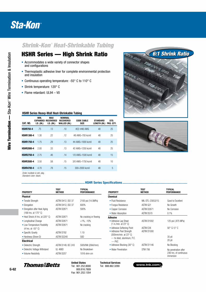
www.tnb.comUnited States
Tel: 901.252.8000 800.816.7809Fax: 901.252.1354
Technical Services
Tel: 888.862.3289G-62
Shrink-Kon ® Heat-Shrinkable Tubing
Wir
e Te
rmin
atio
n —
Sta
-Kon
® W
ire T
erm
inat
ion
& In
sula
tion
.............................................................................HSHR Series Specifications ...............................................................................
HSHR Series Heavy-Wall Heat-Shrinkable Tubing
CAT. NO.
MIN.
EXPANDED
I.D. (IN.)
MAX
RECOVERED
I.D. (IN.)
NOMINAL
RECOVERED
WALLED (IN.)
CODE CABLE
SIZE
STANDARD
LENGTH (IN.)
STD.
PKG. QTY.
HSHR750-4 .75 .13 .10 #22–#46 AWG 48 25
HSHR1300-4 1.30 .22 .12 #8 AWG–700 kcmil 48 25
HSHR1750-4 1.75 .29 .13 #4 AWG–1000 kcmil 48 25
HSHR2000-4 2.00 .33 .13 #2 AWG–1250 kcmil 48 25
HSHR2750-4 2.75 .46 .14 1/0 AWG–1500 kcmil 48 15
HSHR3500-4 3.50 .58 .15 3/0 AWG–1750 kcmil 48 10
HSHR4700-4 4.70 .78 .15 300–2000 kcmil 48 5
Order multiple is std. pkg.
Standard color: black.
PROPERTY
TEST
METHOD
TYPICAL
PERFORMANCE
Physical
Tensile Strength ASTM D412, ISO 37 2100 psi (14.5MPa)
Elongation ASTM D412, ISO 37 600%
Elongation after Heat Aging ASTM D2671 500%
(168 hrs. at 175° C)
Heat Shock (4 hrs. at 225° C) ASTM D2671 No cracking or flowing
Longitudinal Change ASTM D2671 +1%, -10%
Low-Temperature Flexibility ASTM D2671 No cracking
(4 hrs. at -55° C)
Specific Gravity ASTM D792 1.10
Hardness (Shore D) ASTM D2240 50D
Electrical
Dielectric Strength ASTM D149, IEC 243 500V/Mil (20kV/mm)
Dielectric Voltage Withstand UL 486D No Breakdown
Volume Resistivity ASTM D257 1016 ohm-cm
PROPERTY
TEST
METHOD
TYPICAL
PERFORMANCE
Chemical
Fluid Resistance MIL-DTL-23053/15 Good to Excellent
Fungus Resistance ASTM G21 No Growth
Copper Corrosion ASTM D2671 No Corrosion
Water Absorption ASTM D570 0.1%
Adhesive
Adhesive Lap Sheer ASTM D1002 125 psi (.875 MPa)(1 in./min. at 23° C)
Adhesive Softening Point ASTM E28 92° C/-5° C
Adhesive Peel Strength
(300mm/min. at 23° C)
— to steel, aluminum, P.E.
— PVC
ASTM D1000
35 pli
20 pli
Adhesive Blocking (30° C) ASTM D1146 No Blocking
Water Penetration STM 706 No penetration after
236 hrs. of continuous
immersion
6:1 Shrink Ratio6:1 Shrink RatioHSHR Series — High Shrink Ratio Accommodates a wide variety of connector shapes and configurations
Thermoplastic adhesive liner for complete environmental protection and insulation
Continuous operating temperature: -55° C to 110° C
Shrink temperature: 120° C
Flame retardant: UL94 – V0
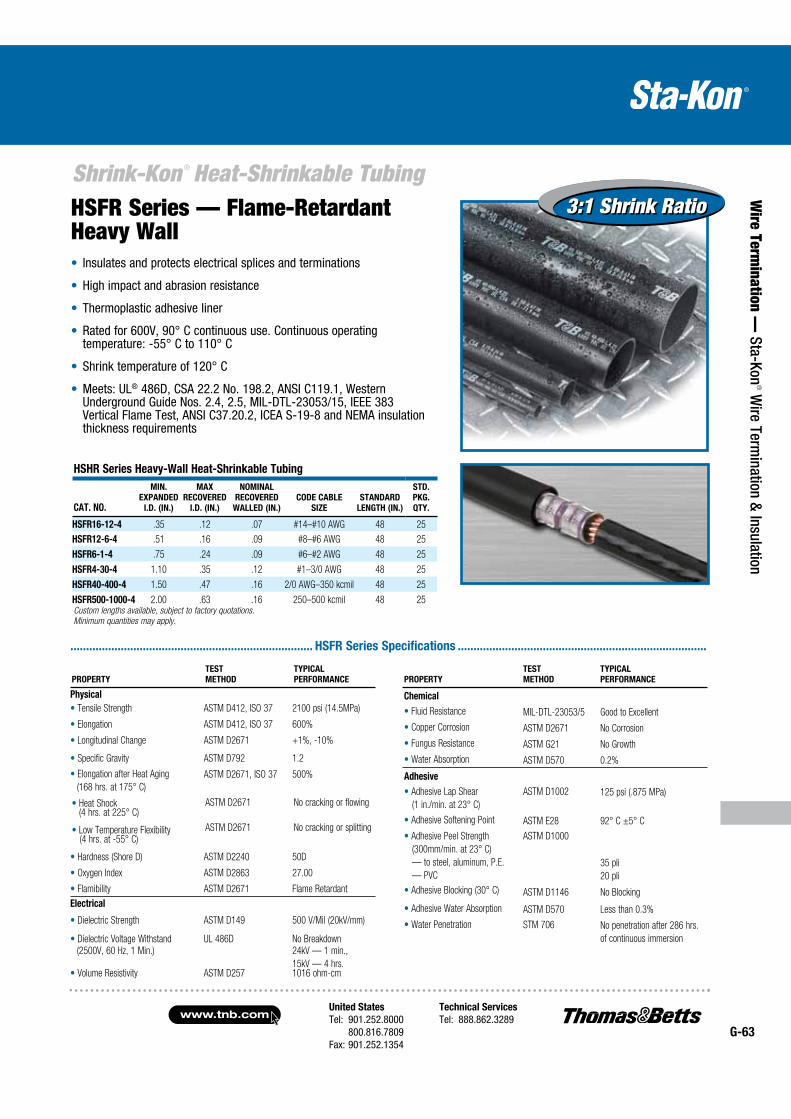
United States
Tel: 901.252.8000 800.816.7809Fax: 901.252.1354
Technical Services
Tel: 888.862.3289www.tnb.com
G-63
Shrink-Kon ® Heat-Shrinkable Tubing
Wire Term
ination — Sta-Kon
® Wire Term
ination & Insulation
Insulates and protects electrical splices and terminations
High impact and abrasion resistance
Thermoplastic adhesive liner
Rated for 600V, 90° C continuous use. Continuous operating temperature: -55° C to 110° C
Shrink temperature of 120° C
Meets: UL® 486D, CSA 22.2 No. 198.2, ANSI C119.1, Western Underground Guide Nos. 2.4, 2.5, MIL-DTL-23053/15, IEEE 383 Vertical Flame Test, ANSI C37.20.2, ICEA S-19-8 and NEMA insulation thickness requirements
............................................................................. HSFR Series Specifications ...............................................................................
HSHR Series Heavy-Wall Heat-Shrinkable Tubing
CAT. NO.
MIN.
EXPANDED
I.D. (IN.)
MAX
RECOVERED
I.D. (IN.)
NOMINAL
RECOVERED
WALLED (IN.)
CODE CABLE
SIZE
STANDARD
LENGTH (IN.)
STD.
PKG.
QTY.
HSFR16-12-4 .35 .12 .07 #14–#10 AWG 48 25
HSFR12-6-4 .51 .16 .09 #8–#6 AWG 48 25
HSFR6-1-4 .75 .24 .09 #6–#2 AWG 48 25
HSFR4-30-4 1.10 .35 .12 #1–3/0 AWG 48 25
HSFR40-400-4 1.50 .47 .16 2/0 AWG–350 kcmil 48 25
HSFR500-1000-4 2.00 .63 .16 250–500 kcmil 48 25Custom lengths available, subject to factory quotations.
Minimum quantities may apply.
PROPERTY
TEST
METHOD
TYPICAL
PERFORMANCE
Chemical
Fluid Resistance MIL-DTL-23053/5 Good to Excellent
Copper Corrosion ASTM D2671 No Corrosion
Fungus Resistance ASTM G21 No Growth
Water Absorption ASTM D570 0.2%
Adhesive
Adhesive Lap Shear
(1 in./min. at 23° C)
ASTM D1002 125 psi (.875 MPa)
Adhesive Softening Point ASTM E28 92° C ±5° C
Adhesive Peel Strength
(300mm/min. at 23° C)
— to steel, aluminum, P.E.
— PVC
ASTM D1000
35 pli
20 pli
Adhesive Blocking (30° C) ASTM D1146 No Blocking
Adhesive Water Absorption ASTM D570 Less than 0.3%
Water Penetration STM 706 No penetration after 286 hrs.
of continuous immersion
PROPERTY
TEST
METHOD
TYPICAL
PERFORMANCE
Physical
Tensile Strength ASTM D412, ISO 37 2100 psi (14.5MPa)
Elongation ASTM D412, ISO 37 600%
Longitudinal Change ASTM D2671 +1%, -10%
Specific Gravity ASTM D792 1.2
Elongation after Heat Aging
(168 hrs. at 175° C)
ASTM D2671, ISO 37 500%
Heat Shock (4 hrs. at 225° C)
ASTM D2671 No cracking or flowing
Low Temperature Flexibility (4 hrs. at -55° C)
ASTM D2671 No cracking or splitting
Hardness (Shore D) ASTM D2240 50D
Oxygen Index ASTM D2863 27.00
Flamibility ASTM D2671 Flame Retardant
Electrical
Dielectric Strength ASTM D149 500 V/Mil (20kV/mm)
Dielectric Voltage Withstand UL 486D No Breakdown
(2500V, 60 Hz, 1 Min.) 24kV — 1 min.,
15kV — 4 hrs.Volume Resistivity ASTM D257 1016 ohm-cm
3:1 Shrink Ratio3:1 Shrink RatioHSFR Series — Flame-Retardant Heavy Wall
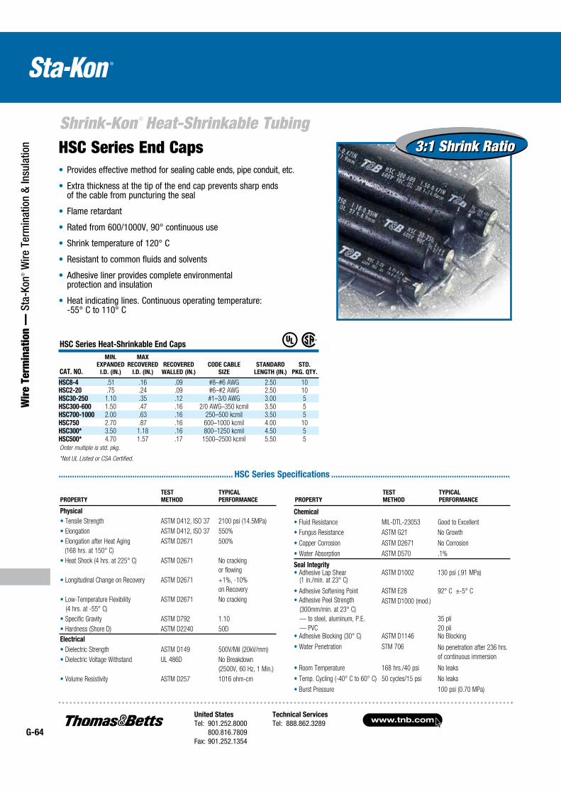
www.tnb.comUnited States
Tel: 901.252.8000 800.816.7809Fax: 901.252.1354
Technical Services
Tel: 888.862.3289G-64
Shrink-Kon ® Heat-Shrinkable Tubing
Wir
e Te
rmin
atio
n —
Sta
-Kon
® W
ire T
erm
inat
ion
& In
sula
tion 3:1 Shrink Ratio3:1 Shrink RatioHSC Series End Caps
Provides effective method for sealing cable ends, pipe conduit, etc.
Extra thickness at the tip of the end cap prevents sharp ends of the cable from puncturing the seal
Flame retardant
Rated from 600/1000V, 90° continuous use
Shrink temperature of 120° C
Resistant to common fluids and solvents
Adhesive liner provides complete environ mental protection and insulation
Heat indicating lines. Continuous operating temperature: -55° C to 110° C
.............................................................................. HSC Series Specifications ................................................................................
PROPERTY
TEST
METHOD
TYPICAL
PERFORMANCE
Physical
Electrical
HSC Series Heat-Shrinkable End Caps
CAT. NO.
MIN.
EXPANDED
I.D. (IN.)
MAX
RECOVERED
I.D. (IN.)
RECOVERED
WALLED (IN.)
CODE CABLE
SIZE
STANDARD
LENGTH (IN.)
STD.
PKG. QTY.
HSC8-4HSC2-20HSC30-250HSC300-600HSC700-1000HSC750HSC300*HSC500*
Order multiple is std. pkg.
*Not UL Listed or CSA Certified.
PROPERTY
TEST
METHOD
TYPICAL
PERFORMANCE
Chemical
Seal Integrity
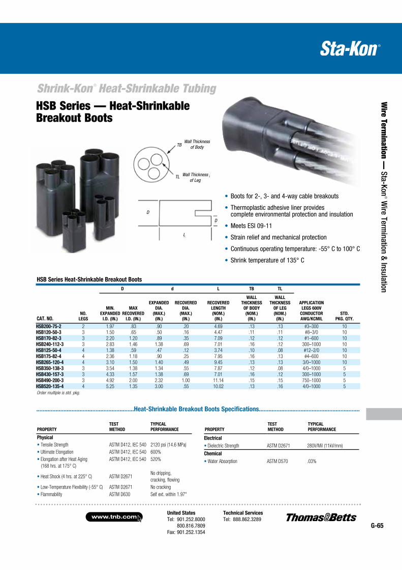
United States
Tel: 901.252.8000 800.816.7809Fax: 901.252.1354
Technical Services
Tel: 888.862.3289www.tnb.com
G-65
Shrink-Kon ® Heat-Shrinkable Tubing
Wire Term
ination — Sta-Kon
® Wire Term
ination & Insulation
HSB Series — Heat-Shrinkable Breakout Boots
Boots for 2-, 3- and 4-way cable breakouts
Thermoplastic adhesive liner provides complete environmental protection and insulation
Meets ESI 09-11
Strain relief and mechanical protection
Continuous operating temperature: -55° C to 100° C
Shrink temperature of 135° C
.............................................................Heat-Shrinkable Breakout Boots Specifications...............................................................
PROPERTY
TEST
METHOD
TYPICAL
PERFORMANCE
Physical
PROPERTY
TEST
METHOD
TYPICAL
PERFORMANCE
Electrical
Chemical
HSB Series Heat-Shrinkable Breakout Boots
CAT. NO.NO.
LEGS
D d L TB TL
APPLICATION
LEGS 600V
CONDUCTOR
AWG/KCMIL
STD.
PKG. QTY.
MIN.
EXPANDED
I.D. (IN.)
MAX
RECOVERED
I.D. (IN.)
EXPANDED
DIA.
(MAX.)
(IN.)
RECOVERED
DIA.
(MAX.)
(IN.)
RECOVERED
LENGTH
(NOM.)
(IN.)
WALL
THICKNESS
OF BODY
(NOM.)
(IN.)
WALL
THICKNESS
OF LEG
(NOM.)
(IN.)
HSB200-75-2HSB120-50-3
HSB170-82-3
HSB240-112-3
HSB125-50-4
HSB175-82-4
HSB265-120-4
HSB350-138-3
HSB430-157-3
HSB490-200-3
HSB520-135-4
Order multiple is std. pkg.
TB
TL
D
L
D
Wall Thickness of Body
Wall Thickness of Leg
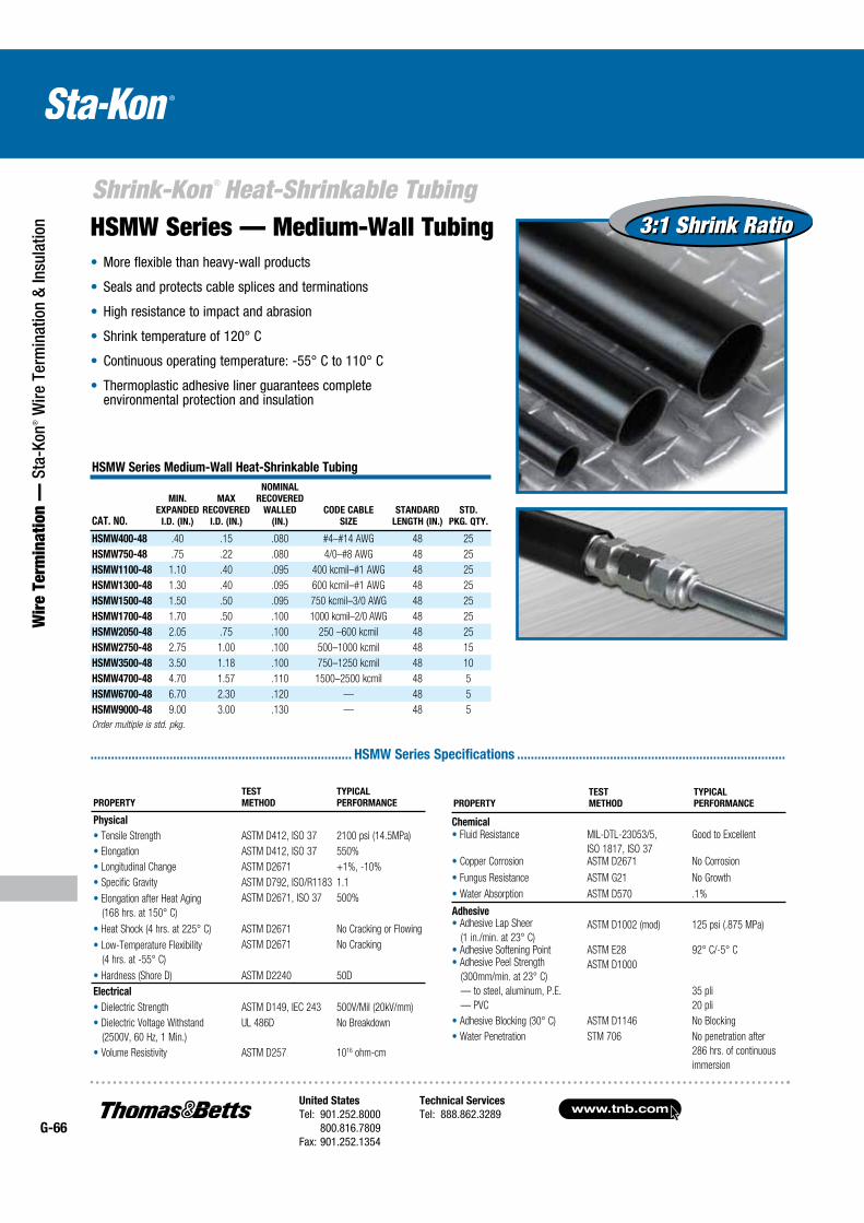
www.tnb.comUnited States
Tel: 901.252.8000 800.816.7809Fax: 901.252.1354
Technical Services
Tel: 888.862.3289G-66
Shrink-Kon ® Heat-Shrinkable Tubing
Wir
e Te
rmin
atio
n —
Sta
-Kon
® W
ire T
erm
inat
ion
& In
sula
tion 3:1 Shrink Ratio3:1 Shrink RatioHSMW Series — Medium-Wall Tubing
More flexible than heavy-wall products
Seals and protects cable splices and terminations
High resistance to impact and abrasion
Shrink temperature of 120° C
Continuous operating temperature: -55° C to 110° C
Thermoplastic adhesive liner guarantees complete environmental protection and insulation
............................................................................ HSMW Series Specifications ..............................................................................
HSMW Series Medium-Wall Heat-Shrinkable Tubing
CAT. NO.
MIN.
EXPANDED
I.D. (IN.)
MAX
RECOVERED
I.D. (IN.)
NOMINAL
RECOVERED
WALLED
(IN.)
CODE CABLE
SIZE
STANDARD
LENGTH (IN.)
STD.
PKG. QTY.
HSMW400-48 .40 .15 .080 #4–#14 AWG 48 25
HSMW750-48 .75 .22 .080 4/0–#8 AWG 48 25
HSMW1100-48 1.10 .40 .095 400 kcmil–#1 AWG 48 25
HSMW1300-48 1.30 .40 .095 600 kcmil–#1 AWG 48 25
HSMW1500-48 1.50 .50 .095 750 kcmil–3/0 AWG 48 25
HSMW1700-48 1.70 .50 .100 1000 kcmil–2/0 AWG 48 25
HSMW2050-48 2.05 .75 .100 250 –600 kcmil 48 25
HSMW2750-48 2.75 1.00 .100 500–1000 kcmil 48 15
HSMW3500-48 3.50 1.18 .100 750–1250 kcmil 48 10
HSMW4700-48 4.70 1.57 .110 1500–2500 kcmil 48 5
HSMW6700-48 6.70 2.30 .120 — 48 5
HSMW9000-48 9.00 3.00 .130 — 48 5
Order multiple is std. pkg.
PROPERTY
TEST
METHOD
TYPICAL
PERFORMANCE
Physical
Tensile Strength ASTM D412, ISO 37 2100 psi (14.5MPa)
Elongation ASTM D412, ISO 37 550%
Longitudinal Change ASTM D2671 +1%, -10%
Specific Gravity ASTM D792, ISO/R1183 1.1
Elongation after Heat Aging
(168 hrs. at 150° C)
ASTM D2671, ISO 37 500%
Heat Shock (4 hrs. at 225° C) ASTM D2671 No Cracking or Flowing
Low-Temperature Flexibility
(4 hrs. at -55° C)
ASTM D2671 No Cracking
Hardness (Shore D) ASTM D2240 50D
Electrical
Dielectric Strength ASTM D149, IEC 243 500V/Mil (20kV/mm)
Dielectric Voltage Withstand
(2500V, 60 Hz, 1 Min.)
UL 486D No Breakdown
Volume Resistivity ASTM D257 1016 ohm-cm
PROPERTY
TEST
METHOD
TYPICAL
PERFORMANCE
ChemicalFluid Resistance MIL-DTL-23053/5,
ISO 1817, ISO 37
Good to Excellent
Copper Corrosion ASTM D2671 No Corrosion
Fungus Resistance ASTM G21 No Growth
Water Absorption ASTM D570 .1%
AdhesiveAdhesive Lap Sheer
(1 in./min. at 23° C)ASTM D1002 (mod) 125 psi (.875 MPa)
Adhesive Softening Point ASTM E28 92° C/-5° CAdhesive Peel Strength
(300mm/min. at 23° C)
— to steel, aluminum, P.E.
— PVC
ASTM D1000
35 pli
20 pli
Adhesive Blocking (30° C) ASTM D1146 No Blocking
Water Penetration STM 706 No penetration after
286 hrs. of continuous
immersion
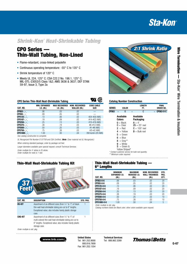
United States
Tel: 901.252.8000 800.816.7809Fax: 901.252.1354
Technical Services
Tel: 888.862.3289www.tnb.com
G-67
Shrink-Kon ® Heat-Shrinkable Tubing
Wire Term
ination — Sta-Kon
® Wire Term
ination & Insulation
CPO Series — Thin-Wall Tubing, Non-Lined
Flame-retardant, cross-linked polyolefin
Continuous operating temperature: -55° C to 135° C
Shrink temperature of 120° C
Meets UL 224, 125° C; CSA C22.2 No. 198.1, 125° C; MIL-DTL-23053/5 Class 1&2; AMS 3636 & 3637; DEF STAN 59-97, Issue 3, Type 2a
Thin-Wall Heat-Shrinkable Tubing Kit
37Feet! 37
Feet!
CPO Series Thin-Wall Heat-Shrinkable Tubing
CAT. NO.MIN. EXPANDED
I.D. (IN.)
MAX RECOVERED
I.D. (IN.)
NOM. RECOVERED
WALLED (IN.)
CODE CABLE
SIZE
CPO63-_-_ .06 .03 .02 —CPO93-_-_ .09 .05 .02 —CPO125-_-_ .13 .06 .02 #24–#30 AWGCPO187-_-_ .19 .09 .02 #14–#22 AWGCPO250-_-_ .25 .13 .03 #10–#16 AWGCPO375-_-_ .38 .19 .03 #6–#12 AWGCPO500-_-_ .50 .25 .03 #1–#6 AWGCPO750-_-_ .75 .38 .03 4/0–#2 AWGCPO1000-_-_ 1.00 .50 .04 350 kcmil–2/0 AWG
See catalog construction to complete.
UL Recognized File Number E137759 and CSA Certified. (Note: Clear material not UL Recognized.)
When ordering standard package, order by package not feet.
Larger diameters available upon special request; consult Technical Services.
Order multiple for 4' sticks is 25 sticks.
Order multiple for reels is 1 reel.
CAT. NO.
MINIMUM
EXPANDED I.D.
(IN.)
MAXIMUM
REDUCED I.D.
(IN.)
NOM. RECOVERED
WALL THICKNESS
(IN.)
STD.
PKG.
QTY.
CPO63-0-6 .06 .03 .02 20CPO93-0-6 .09 .05 .02 20CPO125-0-6 .13 .06 .02 20CPO187-0-6 .19 .09 .02 20CPO250-0-6 .25 .13 .03 20CPO375-0-6 .38 .19 .03 20CPO500-0-6 .50 .25 .03 10CPO750-0-6 .75 .38 .03 10CPO1000-0-6 1.00 .50 .04 5
Order multiple is std. pkg.
Catalog numbers listed are Black color; other colors available upon request.
Catalog Number Construction
SERIES COLOR
LENGTH
FT.
FINAL
ORDER NO.
CPO63 + O + C = CPO63-O-C
Available
Colors
Available
Packaging
0 = Black A = 4'C = Clear 25 = 25' reel
2 = Red C = 100' reel
4 = Yellow B = Bulk reel
5 = Green
6 = Blue
8 = Gray**
9 = WhiteS = Green &Yellow Striped*
* Contact customer service for bulk reel quantity.
** Minimum order required.
2:1 Shrink Ratio2:1 Shrink Ratio
CAT. NO. DESCRIPTION STD. PKG.
HS-KIT Assortment of six different sizes (from 3⁄16" to 1") of black
thin-wall heat-shrinkable tubing pre-cut to 6" lengths.
Exceptional value; also includes handy plastic storage
case.
1
CHS-KIT Assortment of six different sizes (from 3⁄16" to 1") of
multi-colored thin-wall heat-shrinkable tubing pre-cut to
6" lengths. Exceptional value; also includes handy plastic
storage case.
1
Order multiple is std. pkg.
Thin-Wall Heat-Shrinkable Tubing — 6" Lengths
www.tnb.comUnited States
Tel: 901.252.8000 800.816.7809Fax: 901.252.1354
Technical Services
Tel: 888.862.3289G-68
Shrink-Kon ® Heat-Shrinkable Tubing
Wir
e Te
rmin
atio
n —
Sta
-Kon
® W
ire T
erm
inat
ion
& In
sula
tion
Example 1
If a bulk length of tubing is 1,000' and the desired length of each individual piece is 6", the minimum order requirement is 2,000 pieces.
Given (length of reel)........................................1,000'
Convert to inches by multiplying by 12.......12 x 1,000
Length of reel in inches ...............................= 12,000
Divide by desired length............................12,000 ÷ 6
Total number of 6" pieces in a 1,000' reel (Minimum Order)................= 2,000
Example 2
If a bulk reel of tubing is 400' and the desired length of each individual piece is 2", the minimum order requirement is 2,400 pieces.
Given (length of reel)...........................................400'
Convert to inches by multiplying by 12..........12 x 400
Length of reel in inches .................................= 4,800
Divide by desired length.............................4,800 ÷ 2
Total number of 2" pieces in a 400' reel (Minimum Order)...................= 2,400
Contact tech services for pricing and availability on cut pieces.
Custom-Cut Length of Bulk Packaging — Thin-Wall TubingTo best meet your requirements for thin-wall heat-shrinkable tubing, Thomas & Betts welcomes the opportunity to cut bulk reels of tubing. Minimum order requirement is one standard bulk reel, and multiples thereof. See table for bulk reel length by size.Tubing cannot be cut smaller than 1⁄2".
When ordering custom-cut lengths of tubing, order by piece, not by length. To determine the minimum number of pieces to order, simply figure how many pieces of a specific length of tubing are required to make use of a complete bulk reel. See examples to convert bulk reels to cut pieces.
Custom order lengths for those special jobs!
SERIESBULK REEL
LENGTH (FT.) SERIESBULK REEL
LENGTH (FT.)
CPO63 = 1⁄16" 1,000 CPO375 = 3⁄8" 500CPO93 = 3⁄32" 1,000 CPO500 = 1⁄2" 400CPO125 = 1⁄8" 1,000 CPO750 = 3⁄4" 300CPO187 = 3⁄16" 1,000 CPO1000 = 1" 300CPO250 = 1⁄4" 1,000
Minimum order quantity for cut pieces.
THINWALL
SERIES
CUT PIECE CATALOG NO. CONSTRUCTION
MINIMUM
EXPANDED I.D. (IN.) COLOR
LENGTH
(IN.)
CPO = 63 = .063 0 = Black XXXX — 4 digits specify 93 = .093 C = Clear length of cut in inches 125 = .125 2 = Red 187 = .187 4 = Yellow 250 = .250 5 = Green 375 = .375 6 = Blue
8 = Gray 500 = .500 9 = White 750 = .750 S = Green & Yellow Striped*
1,000 = 1.000
Example: CPO + 125 + 2 + 1.500 = CPO125-2-1.500CPO Thinwall Shrink, size 125 (.125"), red color, 1.5" long
*Contact customer service for bulk reel quantity.
PROPERTY
TEST
METHOD
TYPICAL
PERFORMANCE
Physical
Tensile Strength ASTM D2671, ISO 37 2,200 psi (15.0 MPa)
Elongation ASTM D2671, ISO 37 400%
Longitudinal Change ASTM D2671 +1%, -10%
2% Secan Modulus ASTM D2671 16,000 psi (110 MPa)
Specific Gravity ASTM D792, ISO/R1183 1.3" (colors) .95" (clear)
Restricted Shrinkage ASTM D2671 No Cracking
Elongation after Heat Aging
(168 hrs. at 175° C)
ASTM D2671 350%
Heat Shock (4 hrs. at 250° C) ASTM D2671 No Cracking or Flowing
Low-Temperature Flexibility
(4 hrs. at -55° C
ASTM D2671 No Cracking or Splitting
Flammability ASTM D2671 Flame Retardant (except Clear)
Electrical
Dielectric Strength ASTM D2671, IEC 243 600V/Mil (24kV/mm)
Volume Resistivity ASTM D2671 1016 O HM-CM
Chemical
Fluid Resistance MIL-DTL-23053/5, ISO 1817, ISO 37 Good to Excellent
Copper Corrosion ASTM D2671 No Corrosion
Water Absorption ASTM D570 .2%
Fungus Resistance ASTM G21 No Growth
................................. Thin-Wall Tubing Specifications .....................................
2:1 Shrink Ratio2:1 Shrink Ratio
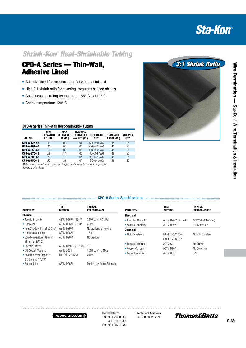
United States
Tel: 901.252.8000 800.816.7809Fax: 901.252.1354
Technical Services
Tel: 888.862.3289www.tnb.com
G-69
Shrink-Kon ® Heat-Shrinkable Tubing
Wire Term
ination — Sta-Kon
® Wire Term
ination & Insulation
3:1 Shrink Ratio3:1 Shrink RatioCPO-A Series — Thin-Wall, Adhesive Lined
Adhesive lined for moisture-proof environmental seal
High 3:1 shrink ratio for covering irregularly shaped objects
Continuous operating temperature: -55° C to 110° C
Shrink temperature 120° C
CPO-A Series Thin-Wall Heat-Shrinkable Tubing
CAT. NO.
MIN.
EXPANDED
I.D. (IN.)
MAX
RECOVERED
I.D. (IN.)
NOMINAL
RECOVERED
WALLED (IN.)
CODE CABLE
SIZE
STANDARD
LENGTH (IN.)
STD. PKG.
QTY.
CPO-A-125-48 .13 .02 .04 #24–#30 AWG 48 25CPO-A-187-48 .18 .06 .05 #14–#22 AWG 48 25CPO-A-250-48 .25 .08 .05 #10–#22 AWG 48 25CPO-A-375-48 .38 .14 .05 #6–#16 AWG 48 25CPO-A-500-48 .50 .19 .07 #2–#12 AWG 48 25CPO-A-750-48 .75 .31 .07 3/0–#4 AWG 48 25
Note: Non-standard colors, sizes and lengths available subject to factory quotation.
Standard color: Black
............................................................................ CPO-A Series Specifications ..............................................................................
PROPERTY
TEST
METHOD
TYPICAL
PERFORMANCE
Physical
Tensile Strength ASTM D2671, ISO 37 2200 psi (15.0 MPa)
Elongation ASTM D2671, ISO 37 400%
Heat Shock (4 hrs. at 250° C) ASTM D2671 No Cracking or Flowing
Longitudinal Change ASTM D2671 ±5%
Low-Temperature Flexibility ASTM D2671 No Cracking
(4 hrs. at -55° C)
Specific Gravity ASTM D792, ISO R1183 1.1
2% Secant Modulus ASTM 2671 1600 psi (110 MPa)
Heat-Resistant Properties MIL-DTL-23053/4 240%
(168 hrs. at 175° C)
Flammability ASTM D2671 Moderately Flame Retardant
PROPERTY
TEST
METHOD
TYPICAL
PERFORMANCE
Electrical
Dielectric Strength ASTM D2671, IEC 243 600V/Mil (24kV/mm)
Volume Resistivity ASTM D2671 1016 ohm-cm
Chemical
Fluid Resistance MIL-DTL-23053/4, Good to Excellent
ISO 1817, ISO 37
Fungus Resistance ASTM G21 No Growth
Copper Corrosion ASTM D2671 No Corrosion
Water Absorption ASTM D570 .2%
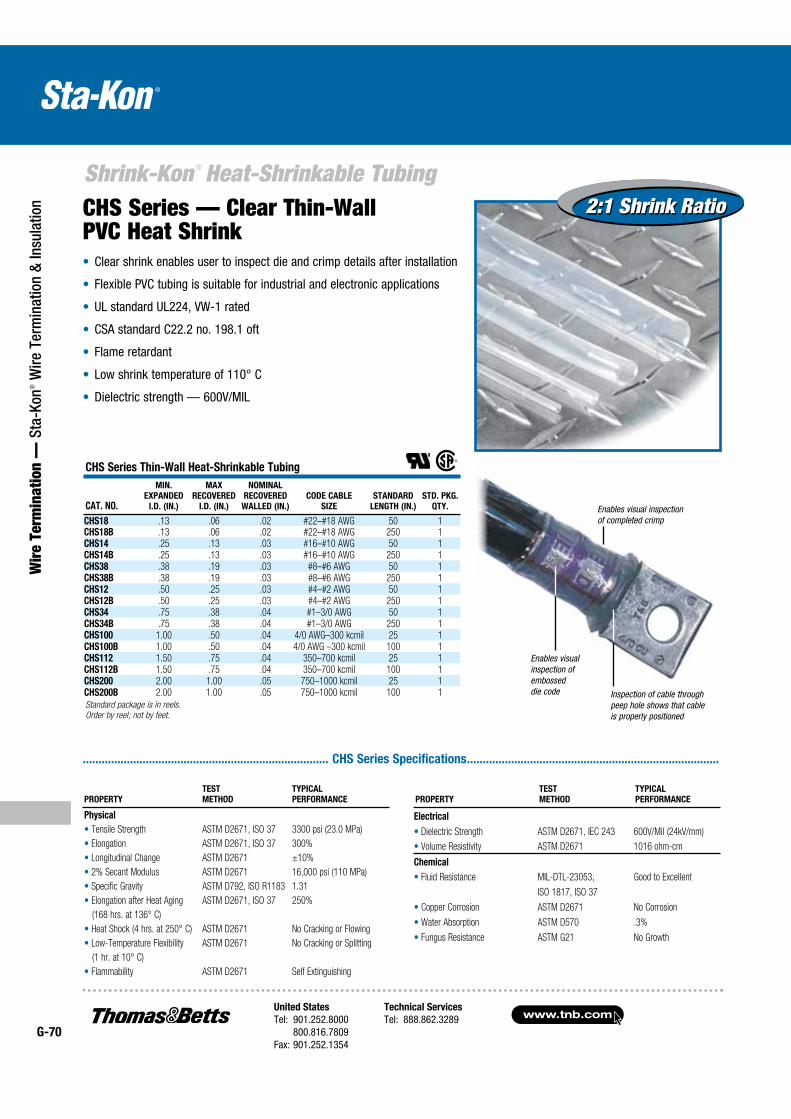
www.tnb.comUnited States
Tel: 901.252.8000 800.816.7809Fax: 901.252.1354
Technical Services
Tel: 888.862.3289G-70
Shrink-Kon ® Heat-Shrinkable Tubing
Wir
e Te
rmin
atio
n —
Sta
-Kon
® W
ire T
erm
inat
ion
& In
sula
tion CHS Series — Clear Thin-Wall
PVC Heat Shrink
Enables visual inspection of embossed die code Inspection of cable through
peep hole shows that cable is properly positioned
Enables visual inspection of completed crimp
.............................................................................. CHS Series Specifications ................................................................................
Clear shrink enables user to inspect die and crimp details after installation
Flexible PVC tubing is suitable for industrial and electronic applications
UL standard UL224, VW-1 rated
CSA standard C22.2 no. 198.1 oft
Flame retardant
Low shrink temperature of 110° C
Dielectric strength — 600V/MIL
CHS Series Thin-Wall Heat-Shrinkable Tubing
CAT. NO.
MIN.
EXPANDED
I.D. (IN.)
MAX
RECOVERED
I.D. (IN.)
NOMINAL
RECOVERED
WALLED (IN.)
CODE CABLE
SIZE
STANDARD
LENGTH (IN.)
STD. PKG.
QTY.
CHS18 .13 .06 .02 #22–#18 AWG 50 1CHS18B .13 .06 .02 #22–#18 AWG 250 1CHS14 .25 .13 .03 #16–#10 AWG 50 1CHS14B .25 .13 .03 #16–#10 AWG 250 1CHS38 .38 .19 .03 #8–#6 AWG 50 1CHS38B .38 .19 .03 #8–#6 AWG 250 1CHS12 .50 .25 .03 #4–#2 AWG 50 1CHS12B .50 .25 .03 #4–#2 AWG 250 1CHS34 .75 .38 .04 #1–3/0 AWG 50 1CHS34B .75 .38 .04 #1–3/0 AWG 250 1CHS100 1.00 .50 .04 4/0 AWG–300 kcmil 25 1CHS100B 1.00 .50 .04 4/0 AWG –300 kcmil 100 1CHS112 1.50 .75 .04 350–700 kcmil 25 1CHS112B 1.50 .75 .04 350–700 kcmil 100 1CHS200 2.00 1.00 .05 750–1000 kcmil 25 1CHS200B 2.00 1.00 .05 750–1000 kcmil 100 1
Standard package is in reels.
Order by reel; not by feet.
PROPERTY
TEST
METHOD
TYPICAL
PERFORMANCE
Physical
Tensile Strength ASTM D2671, ISO 37 3300 psi (23.0 MPa)
Elongation ASTM D2671, ISO 37 300%
Longitudinal Change ASTM D2671 ±10%
2% Secant Modulus ASTM D2671 16,000 psi (110 MPa)
Specific Gravity ASTM D792, ISO R1183 1.31
Elongation after Heat Aging ASTM D2671, ISO 37 250%
(168 hrs. at 136° C)
Heat Shock (4 hrs. at 250° C) ASTM D2671 No Cracking or Flowing
Low-Temperature Flexibility ASTM D2671 No Cracking or Splitting
(1 hr. at 10° C)
Flammability ASTM D2671 Self Extinguishing
PROPERTY
TEST
METHOD
TYPICAL
PERFORMANCE
Electrical
Dielectric Strength ASTM D2671, IEC 243 600V/Mil (24kV/mm)
Volume Resistivity ASTM D2671 1016 ohm-cm
Chemical
Fluid Resistance MIL-DTL-23053, Good to Excellent
ISO 1817, ISO 37
Copper Corrosion ASTM D2671 No Corrosion
Water Absorption ASTM D570 .3%
Fungus Resistance ASTM G21 No Growth
2:1 Shrink Ratio2:1 Shrink Ratio
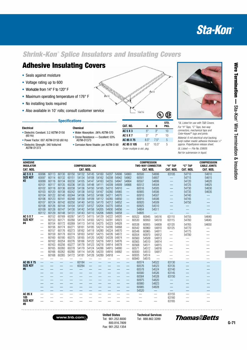
United States
Tel: 901.252.8000 800.816.7809Fax: 901.252.1354
Technical Services
Tel: 888.862.3289www.tnb.com
G-71
Shrink-Kon ® Splice Insulators and Insulating Covers
Wire Term
ination — Sta-Kon
® Wire Term
ination & Insulation
ADHESIVE
INSULATOR
CAT. NOS.
COMPRESSION LUG
CAT. NOS.
COMPRESSION
TWO-WAY CONNECTOR
CAT. NOS.
“H” TAP
CAT. NOS.
“C” TAP
CAT. NOS.
COMPRESSOON
CABLE JOINTS
CAT. NOS.
AC 5 X 3SIZE KEY#2
60096 60113 60130 60150 54132 54145 54160 54207 54906 54860 60500 54806 63105 54710 5461060097 60114 60132 60151 54134 54108 54162 54208 54942 54862 60501 54807 — 54715 5461560099 60116 60134 60230 54105 54147 54163 54255 54947 54864 60507 54806 — 54720 5462060101 60117 60135 60236 54135 54148 54111 54209 54909 54866 60512 54504 — 54725 5462560102 60118 60136 60238 54136 54150 54165 54210 54910 — 60516 54505 — 54730 5463060103 60120 60138 60242 54138 54152 54167 54260 54965 — 60905 54506 — 54735 5463560104 60122 60140 60244 54106 54153 54168 54211 54970 — 60910 54507 — 54740 —60106 60123 60141 60248 54139 54109 54112 54265 54850 — 60915 54506 — 54745 —60107 60124 60142 60250 54140 54155 54170 54212 54852 — 60920 54509 — 54750 —60108 60126 60144 54104 54107 54157 54204 54270 54854 — 60925 54510 — — —60109 60128 60147 54130 54142 54158 54205 54930 54856 — 54804 54511 — — —60112 60129 60148 54131 54143 54110 54206 54905 54858 — 54805 — — — —
AC 5 X 7SIZE KEY#4
— 60152 60169 60267 54173 54115 54129 54222 54920 —— 60153 60171 60268 54174 54183 54213 54291 54923 —— 60154 60172 60269 54113 54116 54275 54223 54928 —— 60156 60174 60271 58161 54185 54214 54295 54868 —— 60157 60176 60273 58162 54118 54280 54224 54870 —— 60159 60178 60274 58163 54187 54215 54226 54872 —— 60160 60180 60275 58165 54120 54282 54228 54874 —— 60162 60254 60276 58166 54122 54216 54913 54876 —— 60163 60256 60277 54178 54123 54218 54914 54878 —— 60165 60260 60278 54179 54124 54286 54915 54880 —— 60166 60262 60280 54114 54126 54220 54916 54882 —— 60168 60265 54172 54181 54128 54289 54918 — —— — — — — — — — — —
AC 85 X 75SIZE KEY#6
— — — — 60184 — — — — — 60574 54522 63130 — —— — — — 60284 — — — — — 60576 54523 63135 — —— — — — — — — — — — 60578 54524 63140 — —— — — — — — — — — — 60580 54526 63145 — —— — — — — — — — — — 60584 54528 63150 — —— — — — — — — — — — 60975 54820 — — —— — — — — — — — — — 60980 54823 — — —— — — — — — — — — — 60985 54828 — — —— — — — — — — — — — 54520 — — — —
AC 85 X 105SIZE KEY#8
— — — — — — — — — — — — 63155 — —— — — — — — — — — — — — 63160 — —— — — — — — — — — — — — 63165 — —
*UL Listed for use with T&B Covers.
For “H” Taps, “C” Taps, two-way
connectors, mechanical taps and
Color-Keyed ® lugs and joints.
Material: 6 mil electrical vinyl backing,
butyl rubber mastic adhesive thickness 1⁄8"
approx. Polyethylene release sheet.
UL Listed — File No. E9809.
Not for submersion in liquid.
Adhesive Insulating Covers
CAT. NO. A B
STD.
PKG.
AC 5 X 3 5" 3" 10
AC 5 X 7 5" 7" 10
AC 85 X 75 8.5" 7.5" 5
AC 85 X 105 8.5" 10.5" 5
Order multiple is std. pkg.
60522 60945 54516 63110 54755 5464060530 60950 54518 63115 54760 54645
60538 60955 54809 63120 54765 5465060542 60960 54810 63125 54770 —60548 60965 54811 — 54775 —60554 60970 54812 — 54780 —60560 54509 54813 — — —60565 54510 54814 — — —60568 54511 54815 — — —60571 54512 54816 — — —60930 54513 54817 — — —60935 54514 — — — —60940 54515 — — — —
Seals against moisture
Voltage rating up to 600
Workable from 14° F to 120° F
Maximum operating temperature of 176° F
No installing tools required
Also available in 10' rolls; consult customer service
Electrical
Dielectric Constant: 3.2 ASTM-D150 (60 Hz)
Power Factor: 007 ASTM-D150 (60 Hz)
Dielectric Strength: 340 Volts/mil ASTM-D1373
Chemical
Water Absorption: .06% ASTM-570
Ozone Resistance — Excellent: 03% ASTM-D1373
Corrosion None Visable: per ASTM-D 69
.................................... Specifications ...................................
B±1⁄8A±1⁄8
1⁄8±1⁄32
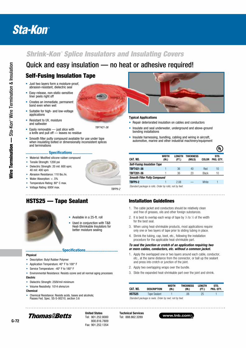
www.tnb.comUnited States
Tel: 901.252.8000 800.816.7809Fax: 901.252.1354
Technical Services
Tel: 888.862.3289G-72
Shrink-Kon ® Splice Insulators and Insulating Covers
Wir
e Te
rmin
atio
n —
Sta
-Kon
® W
ire T
erm
inat
ion
& In
sula
tion
Available in a 25-ft. roll
Used in conjunction with T&B Heat-Shrinkable Insulators for better moisture sealing
CAT. NO. DESCRIPTION
WIDTH
(IN.)
THICKNESS
(IN.)
LENGTH
(FT.)
STD.
PKG. QTY.
HSTS25 Tape Sealant 1 .06 25 1
Standard package is reels. Order by reel; not by feet.
1. The cable jacket and conductors should be relatively clean and free of greases, oils and other foreign substances.
2. It is best to overlap each wrap of tape by 1⁄4 to 1⁄2 of the width for the best seal.
3. When using heat-shrinkable products, most applications require only one or two layers of tape prior to sliding tubing in place.
4. Shrink the tubing, cap, boot, etc., following the installation procedure for the applicable heat-shrinkable part.
To seal the junction or crotch of an application requiring two or more cables, conductors, etc. without a common jacket.
1. Apply the overlapped one or two layers around each cable, conductor, etc., at the same distance from the connector, or ball up the sealant and press into crotch or junction of the joint.
2. Apply two overlapping wraps over the bundle.
3. Slide the expanded heat-shrinkable part over the joint and shrink.
Installation GuidelinesHSTS25 — Tape Sealant
CAT. NO.WIDTH
(IN.)
LENGTH
(FT.)
THICKNESS
(MILS) COLOR
STD.
PKG. QTY.
Self-Fusing Insulation Tape
TBFT421-36 1 36 40 Red 10
TBFT201-36 1 36 20 Black 10
Smooth Filler Putty Compound
TBFP9-2 1 2.08 — White 1
Standard package is rolls. Order by rolls; not by feet.
Typical Applications
Repair deteriorated insulation on cables and conductors
Insulate and seal underwater, underground and above-ground bonding installations
Insulate harnessing, bundling, cabling and wiring in aircraft, automotive, marine and other industrial machinery/equipment
Material: Modified silicone rubber compound Tensile Strength: 1200 psi Dielectric Strength: 20 mil: 600 vpm;
40 mil: 400 vpm Abrasion Resistance: 110 lbs./in. Water Absorption: < .5% Temperature Rating: 80° C max. Voltage Rating: 600V max.
Quick and easy insulation — no heat or adhesive required!Self-Fusing Insulation Tape
Just two layers form a moisture-proof, abrasion-resistant, dielectric seal
Easy-release, non-static-sensitive liner peels right off
Creates an immediate, permanent bond even when wet
Suitable for high- and low-voltage applications
Resistant to UV, moisture and saltwater
Easily removable — just slice with a knife and pull off — leaves no residue
Smooth filler putty compound available for use under tape when insulating bolted or dimensionally inconsistent splices and terminations
TBFP9-2
TBFT421-36
....................... Specifications ....................
.....................................Specifications .................................
Physical
Description: Butyl Rubber Polymer
Application Temperature: 40° F to 100° F
Service Temperature: -40° F to 180° F
Environmental Resistance: Resists ozone and all normal aging processesElectric
Dielectric Strength: 250V/mil minimum
Volume Resistivity: 1014 ohms/cmChemical
Chemical Resistance: Resists acids, bases and alcohols; Passes Fed. Spec. SS-S-00210, section 3.6

United States
Tel: 901.252.8000 800.816.7809Fax: 901.252.1354
Technical Services
Tel: 888.862.3289www.tnb.com
G-73
Shrink-Kon ® Insulators and Insulating Covers
Wire Term
ination — Sta-Kon
® Wire Term
ination & Insulation
CAT. NO.WIRE
RANGE
INSULATION
O.D.
RANGE
(IN.)
BOLT
MAX.
LENGTH
(IN.)
LENGTH
L
(IN.)
DIA.
A
(IN.)
DIA.
B
(IN.)
DIA.
C
(IN.)
STD.
PKG.
QTY.
MSCV20 #2 AWG–350 kcmil .38–.84 1.25 6.5 3 221⁄32 2 5
Order in multiples of std. pkg.
Wide Range Splice
Quick and dependable way to insulate and waterproof motor lead connections up to 5kV.
Medium-Voltage Motor Stub Splice Insulator Installs in seconds
Flame retardant
Flexible boot and impact-resistant cap
Long lasting and reusable
Waterproof and abrasion resistant
One size fits all hookups — reduces inventory
Enables easy inspection of connection
This first-generation multi-splice insulator is designed to give you a quick, dependable means of protecting medium-voltage motor stub splice connec-tions up to 5kV. You can install it in seconds simply by pushing the cover and boot together. Once installed, it completely waterproofs the connection and provides excellent protection against abrasion or mechanical abuse.
One size reduces inventory
The insulator accommodates wire sizes #2 AWG–350 kcmil having outer diameters of .375" to .840". This range-taking feature should accommodate all of your medium-voltage motor hookups.
Inspectable and reusable
The insulator consists of just two parts: an elastomer boot and thermoplastic cap. The boot has two tapered cable entry legs that fit snugly around the cable to form a watertight seal. The legs are designed to be trimmed during installation to fit the required cable size tightly. The cap simply pushes into a groove in the boot — and pulls out easily when you want to inspect the connection. Removal of the cap does not disturb the seal around the cables, nor does it interrupt the bolted splice connection.
Quality engineered
The boot is made of flexible, abrasion-resistant elastomer, and the cap is made of high impact-resistant thermoplastic — high-performance materials you can depend on. Use the insulator for pigtail applications in motor junction boxes, manholes or wherever a waterproof, impact-resistant insulator is required.
5kV Wire Range: #8–2/0 AWG
Rating: 90° C Applications
UL Listed to: 600V
CSA Certified to: 600V
T&B Recommended to: 5000V @ 90° C
Material: Cap — NORYL, UL 94V-1 Boot — EPDM Elastomer, UL94V-2 Lubricant — Silicone Grease
.....................................Specifications .................................
A C B
L
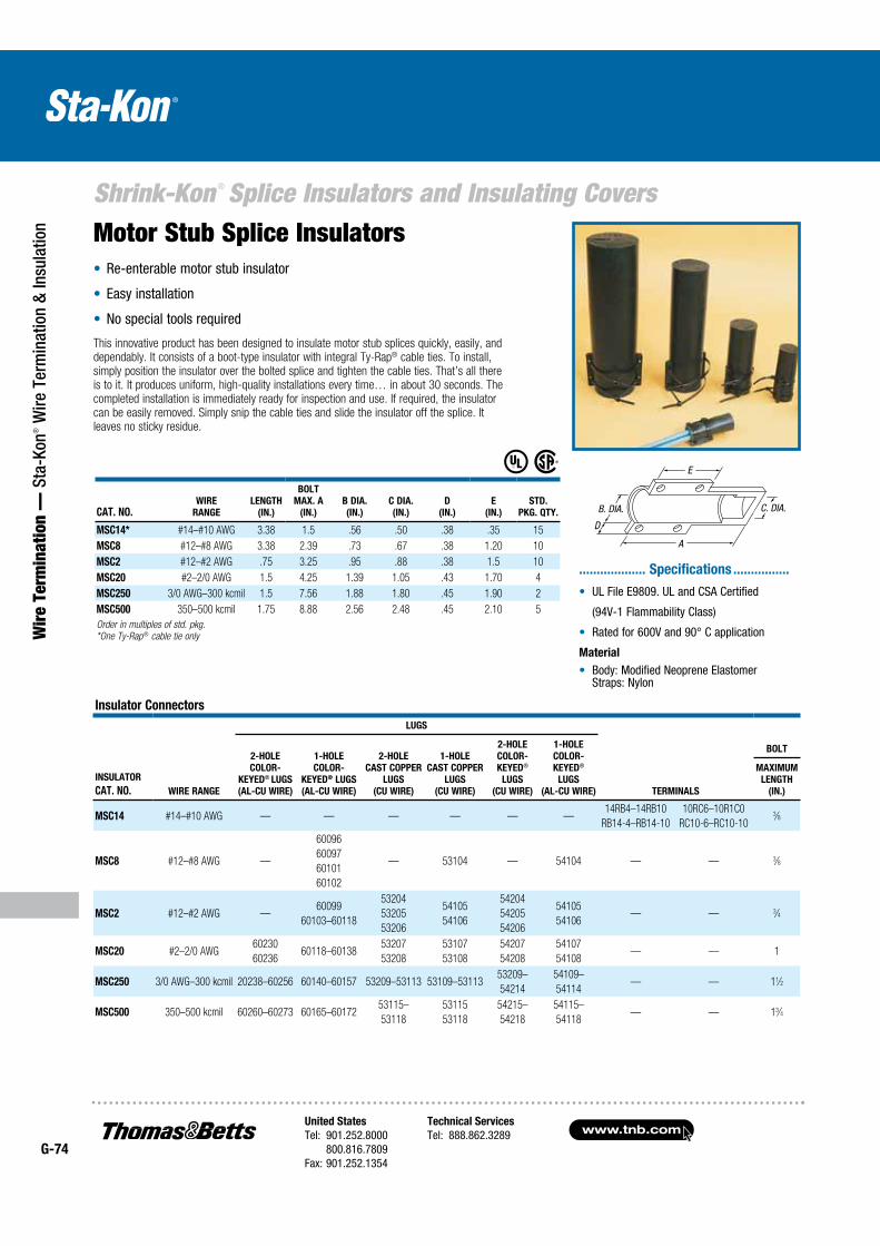
www.tnb.comUnited States
Tel: 901.252.8000 800.816.7809Fax: 901.252.1354
Technical Services
Tel: 888.862.3289G-74
Shrink-Kon ® Splice Insulators and Insulating Covers
Wir
e Te
rmin
atio
n —
Sta
-Kon
® W
ire T
erm
inat
ion
& In
sula
tion
Re-enterable motor stub insulator
Easy installation
No special tools required
Motor Stub Splice Insulators
This innovative product has been designed to insulate motor stub splices quickly, easily, and dependably. It consists of a boot-type insulator with integral Ty-Rap® cable ties. To install, simply position the insulator over the bolted splice and tighten the cable ties. That’s all there is to it. It produces uniform, high-quality installations every time… in about 30 seconds. The completed installation is immediately ready for inspection and use. If required, the insulator can be easily removed. Simply snip the cable ties and slide the insulator off the splice. It leaves no sticky residue.
UL File E9809. UL and CSA Certified
(94V-1 Flammability Class)
Rated for 600V and 90° C application
Material
Body: Modified Neoprene Elastomer Straps: Nylon
................... Specifications ................
CAT. NO.WIRE
RANGE
LENGTH
(IN.)
BOLT
MAX. A
(IN.)
B DIA.
(IN.)
C DIA.
(IN.)
D
(IN.)
E
(IN.)
STD.
PKG. QTY.
MSC14* #14–#10 AWG 3.38 1.5 .56 .50 .38 .35 15
MSC8 #12–#8 AWG 3.38 2.39 .73 .67 .38 1.20 10
MSC2 #12–#2 AWG .75 3.25 .95 .88 .38 1.5 10
MSC20 #2–2/0 AWG 1.5 4.25 1.39 1.05 .43 1.70 4
MSC250 3/0 AWG–300 kcmil 1.5 7.56 1.88 1.80 .45 1.90 2
MSC500 350–500 kcmil 1.75 8.88 2.56 2.48 .45 2.10 5
Order in multiples of std. pkg.
*One Ty-Rap® cable tie only
Insulator Connectors
INSULATOR
CAT. NO. WIRE RANGE
LUGS
TERMINALS
BOLT2-HOLE
COLOR-
KEYED® LUGS
(AL-CU WIRE)
1-HOLE
COLOR-
KEYED® LUGS
(AL-CU WIRE)
2-HOLE
CAST COPPER
LUGS
(CU WIRE)
1-HOLE
CAST COPPER
LUGS
(CU WIRE)
2-HOLE
COLOR-
KEYED®
LUGS
(CU WIRE)
1-HOLE
COLOR-
KEYED®
LUGS
(AL-CU WIRE)
MAXIMUM
LENGTH
(IN.)
MSC14 #14–#10 AWG — — — — — —14RB4–14RB10
RB14-4–RB14-10
10RC6–10R1C0
RC10-6–RC10-103⁄8
MSC8 #12–#8 AWG —
60096
60097
60101
60102
— 53104 — 54104 — — 3⁄8
MSC2 #12–#2 AWG —60099
60103–60118
53204
53205
53206
54105
54106
54204
54205
54206
54105
54106— — 3⁄4
MSC20 #2–2/0 AWG60230
6023660118–60138
53207
53208
53107
53108
54207
54208
54107
54108— — 1
MSC250 3/0 AWG–300 kcmil 20238–60256 60140–60157 53209–53113 53109–5311353209–
54214
54109–
54114— — 11⁄2
MSC500 350–500 kcmil 60260–60273 60165–6017253115–
53118
53115
53118
54215–
54218
54115–
54118— — 13⁄4
D
A
E
B. DIA. C. DIA.
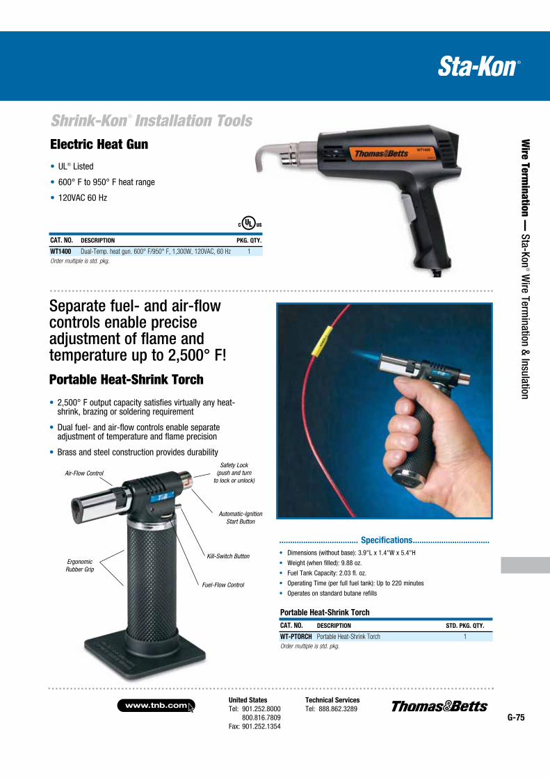
United States
Tel: 901.252.8000 800.816.7809Fax: 901.252.1354
Technical Services
Tel: 888.862.3289www.tnb.com
G-75
Shrink-Kon ® Installation Tools
Wire Term
ination — Sta-Kon
® Wire Term
ination & Insulation
Electric Heat Gun UL® Listed
600° F to 950° F heat range
120VAC 60 Hz
Separate fuel- and air-flow controls enable precise adjustment of flame and temperature up to 2,500° F!Portable Heat-Shrink Torch
2,500° F output capacity satisfies virtually any heat-shrink, brazing or soldering requirement
Dual fuel- and air-flow controls enable separate adjustment of temperature and flame precision
Brass and steel construction provides durability
Ergonomic Rubber Grip
Air-Flow ControlSafety Lock
(push and turn to lock or unlock)
Kill-Switch Button
Fuel-Flow Control
Automatic-Ignition Start Button
Dimensions (without base): 3.9"L x 1.4"W x 5.4"H
Weight (when filled): 9.88 oz.
Fuel Tank Capacity: 2.03 fl. oz.
Operating Time (per full fuel tank): Up to 220 minutes
Operates on standard butane refills
.................................... Specifications ...................................
CAT. NO. DESCRIPTION PKG. QTY.
WT1400 Dual-Temp. heat gun. 600° F/950° F, 1,300W, 120VAC, 60 Hz 1
Order multiple is std. pkg.
Portable Heat-Shrink Torch
CAT. NO. DESCRIPTION STD. PKG. QTY.
WT-PTORCH Portable Heat-Shrink Torch 1
Order multiple is std. pkg.
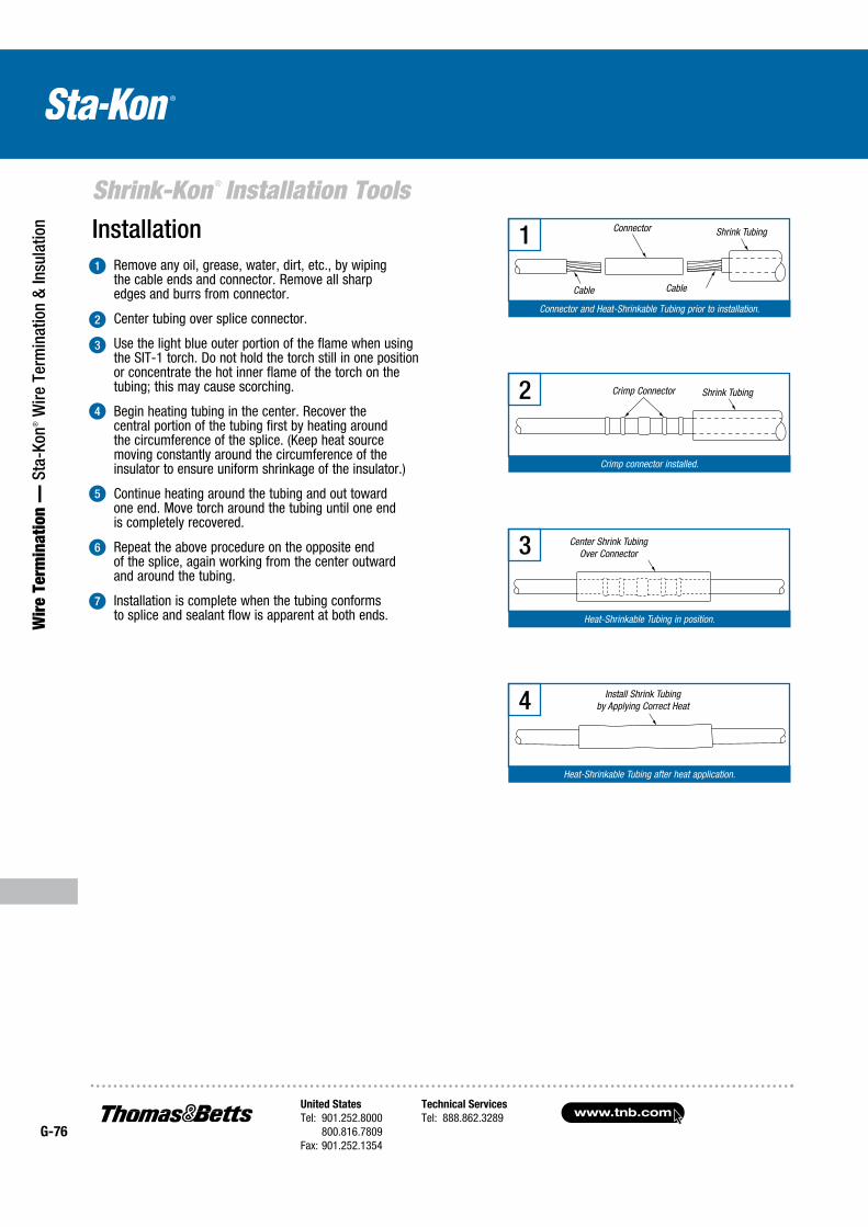
www.tnb.comUnited States
Tel: 901.252.8000 800.816.7809Fax: 901.252.1354
Technical Services
Tel: 888.862.3289G-76
Shrink-Kon ® Installation Tools
Wir
e Te
rmin
atio
n —
Sta
-Kon
® W
ire T
erm
inat
ion
& In
sula
tion
Remove any oil, grease, water, dirt, etc., by wiping the cable ends and connector. Remove all sharp edges and burrs from connector.
Center tubing over splice connector.
Use the light blue outer portion of the flame when using the SIT-1 torch. Do not hold the torch still in one position or concentrate the hot inner flame of the torch on the tubing; this may cause scorching.
Begin heating tubing in the center. Recover the central portion of the tubing first by heating around the circumference of the splice. (Keep heat source moving constantly around the circumference of the insulator to ensure uniform shrinkage of the insulator.)
Continue heating around the tubing and out toward one end. Move torch around the tubing until one end is completely recovered.
Repeat the above procedure on the opposite end of the splice, again working from the center outward and around the tubing.
Installation is complete when the tubing conforms to splice and sealant flow is apparent at both ends.
Installation1
2
3
4
5
6
7
Connector and Heat-Shrinkable Tubing prior to installation.
1 Connector Shrink Tubing
CableCable
Crimp connector installed.
2 Shrink TubingCrimp Connector
Heat-Shrinkable Tubing in position.
3 Center Shrink Tubing Over Connector
Heat-Shrinkable Tubing after heat application.
4 Install Shrink Tubing by Applying Correct Heat
United States
Tel: 901.252.8000 800.816.7809Fax: 901.252.1354
Technical Services
Tel: 888.862.3289www.tnb.com
G-77
Shrink-Kon ® Installation Tools
Wire Term
ination — Sta-Kon
® Wire Term
ination & Insulation
Cross ReferenceT&B PANDUIT 3M RAYCHEM SUMITOMO ALPHA COLEFLEX INSULTAB
CPO HSTT FP 301 ( 1 & 2) RNF 100 (1 & 2) A2 & B2 FIT 221 ST221 / STS221
STU221 / STSU221
HS 101
CPO-A HSTTA & HSTTVA EPS300 TAT 125
ATUM 3:1
W3B2 FIT321 ST303 HS101 MW 3:1
HSMW — — MWTM (U)
BSTS-M / SST-M
CTV
HS — — WSCM / SST — FIT 700 — —
HS FR HST HDT BSTS FR / SSTFR
WCSF / FCSM
— — — CTVH
HSC HSEC ICEC S3C/ESC
SSC-FR / ESC-FR
— — TYT —
CPO-HF — — — NH — — —
HSM-HF — — XFFR — — — —
CHS HSTTPN — — — — — —
These competitor names are the property of the respective competitor.
Cost and Reliability of Heat-Shrinkable Tubing Compared to Tape
The cost differential in the installation of T&B heat-shrinkable tubing over taping can result in up to a 34% savings in labor and overhead. For example, on a 2/0 AWG aluminum splice, heat-shrinkable tubing can be installed in three minutes, versus 10 minutes of taping. In addition to the direct cost reduction, there are the advantages of assured uniformity of wall thickness and moisture sealing.
Typical Specifications
Insulating and sealing of all 600V, in-line cable splices from #16 AWG through 1000 kcmil shall be done in accordance with the instructions provided with the Shrink-Kon® heat-shrinkable insulators, catalog series HS.
The connector insulator must be made of thermally stabilized, homogeneous polyolefin having internally applied sealant. It must have Underwriter’s Laboratories Listing (UL® 486, 90° C, 600V) and be approved for the use. It must be usable without additional covering or adhesive both indoors and outdoors, in overhead, direct-burial or submersed applications at rated voltage. It must not be adversely affected by moisture, ozone, oils, fuels, mild acids and alkalies or ultraviolet light. It must be compatible with all commonly used cable jacket materials, including rubber, plastic, lead, steel, aluminum and copper.
Factory-Applied Sealant
A standard sealant is coated on the entire inside surface of most precut sizes. Tubing is also available without sealant — consult factory. The sealant is rated for continuous 90° C operation on non-pressurized cable systems and aids in sealing out moisture and corrosion.
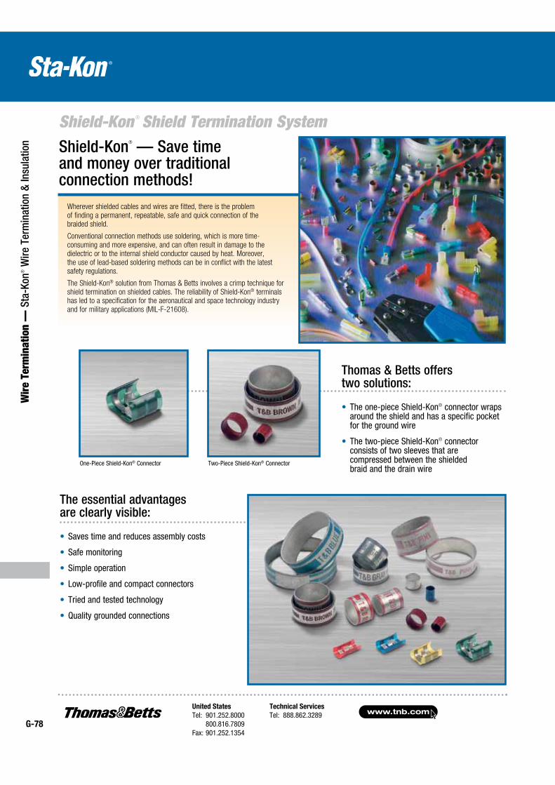
www.tnb.comUnited States
Tel: 901.252.8000 800.816.7809Fax: 901.252.1354
Technical Services
Tel: 888.862.3289G-78
Shield-Kon ® Shield Termination System
Wir
e Te
rmin
atio
n —
Sta
-Kon
® W
ire T
erm
inat
ion
& In
sula
tion
Wherever shielded cables and wires are fitted, there is the problem of finding a permanent, repeatable, safe and quick connection of the braided shield.
Conventional connection methods use soldering, which is more time-consuming and more expensive, and can often result in damage to the dielectric or to the internal shield conductor caused by heat. Moreover, the use of lead-based soldering methods can be in conflict with the latest safety regulations.
The Shield-Kon® solution from Thomas & Betts involves a crimp technique for shield termination on shielded cables. The reliability of Shield-Kon® terminals has led to a specification for the aeronautical and space technology industry and for military applications (MIL-F-21608).
The one-piece Shield-Kon® connector wraps around the shield and has a specific pocket for the ground wire
The two-piece Shield-Kon® connector consists of two sleeves that are compressed between the shielded braid and the drain wire
Shield-Kon® — Save time and money over traditional connection methods!
Thomas & Betts offers two solutions:
Saves time and reduces assembly costs
Safe monitoring
Simple operation
Low-profile and compact connectors
Tried and tested technology
Quality grounded connections
The essential advantages are clearly visible:
One-Piece Shield-Kon® Connector Two-Piece Shield-Kon® Connector
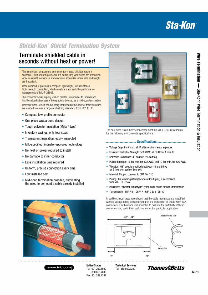
United States
Tel: 901.252.8000 800.816.7809Fax: 901.252.1354
Technical Services
Tel: 888.862.3289www.tnb.com
G-79
Shield-Kon ® Shield Termination System
Wire Term
ination — Sta-Kon
® Wire Term
ination & Insulation
This solderless, wraparound connector terminates shielded cable in seconds... with uniform precision. It’s particularly well suited for production work in aircraft, aerospace and electronic industries where size and weight are important.
Once crimped, it provides a compact, lightweight, low-resistance, high-strength connection, which meets and exceeds the performance requirements of MIL-F-21608.
The connector works equally well on braided, wrapped or foil shields and has the added advantage of being able to be used as a mid-span termination.
Only four sizes, which can be easily identified by the color of their insulation, are needed to cover a range of shielding diameters from .05" to .3".
Compact, low-profile connector
One piece wraparound design
Tough polyester insulation (Mylar® type)
Inventory savings: only four sizes
Transparent insulation, easily inspected
MIL-specified, industry-approved technology
No heat or power required to install
No damage to inner conductor
Less installation time required
Uniform, precise connection every time
Low installed cost
Mid-span termination possible, eliminating the need to demount a cable already installed
Terminate shielded cable in seconds without heat or power!
The one-piece Shield-Kon® connectors meet the MIL-F-21608 standards for the following environmental specifications:
Voltage Drop: 9 mV max. at 1A after environmental exposure
Insulation Dielectric Strength: 500 VRMS at 60 Hz for 1 minute
Corrosion Resistance: 48 hours in 5% salt fog
Pullout Strength: 15 lbs. min. for #22 AWG, and 19 lbs. min. for #20 AWG
Vibration: .03" double amplitude between 10 and 55 Hz for 6 hours on each of two axis
Material: Copper, conform to CDA No. 110
Plating: Tin, electro-plated (thickness 3 to 8 μm), in accordance with MIL-T-10727A
Insulation: Polyester film (Mylar® type), color coded for size identification
Temperature: -85° F to +257° F (-65° C to +125° C)
.................................... Specifications ...................................
.59" – .64"
.11" .11"
Ground wire trap
Insulation
In addition, hypot tests have shown that the cable manufacturers’ specified working voltage rating is maintained after the installation of Shield-Kon® RSK connectors. It is, however, still advisable to evaluate the suitability of these connectors and verify their performance for the particular application.
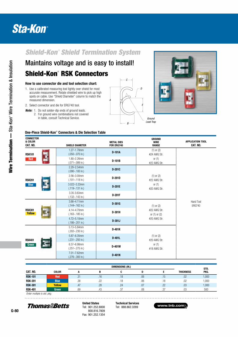
www.tnb.comUnited States
Tel: 901.252.8000 800.816.7809Fax: 901.252.1354
Technical Services
Tel: 888.862.3289G-80
Shield-Kon ® Shield Termination System
Wir
e Te
rmin
atio
n —
Sta
-Kon
® W
ire T
erm
inat
ion
& In
sula
tion
CONNECTOR
& COLOR
CAT. NO. SHIELD DIAMETER
METAL DIES
FOR ERG740
GROUND
WIRE
RANGE
APPLICATION TOOL
CAT. NO.
RSK101
1.27–1.78mm
(.050–.070 in.)D-101A
(1) or (2)
Hand Tool
ERG740
#24 AWG Str.
Red 1.80–2.26mm
(.071–.089 in.)D-101B
or (1)
#22 AWG Str.
2.29–2.54mm
(.090–.100 in.)D-201C
RSK201
2.56–3.00mm
(.101–.118 in.)D-201D
(1) or (2)
#22 AWG Str.
Blue 3.022–3.33mm
(.119–.131 in.)D-201E
or (1)
#20 AWG Str.
3.35-3.63mm
(.132–.143 in.)D-201F
3.66–4.11mm
(.144–.162 in.)D-301G
(1) or (2)
RSK301Yellow
4.14–4.70mm
(.163–.185 in.)D-301H
#22 AWG Str.
or (1) or (2)
4.72–5.10mm
(.186–.201 in.)D-301J
#20 AWG Str.
5.13–5.84mm
(.202–.230 in.)D-401K
RSK401
5.87–6.35mm
(.231–.250 in.)D-401L
(1) or (2)
#20 AWG Str.
Green 6.37–6.98mm
(.251–.275 in.)D-401M
or (1)
#18 AWG Str.
7.01–7.62mm
(.276–.300 in.)D-401N
Maintains voltage and is easy to install!
Shield-Kon® RSK Connectors
CAT. NO. COLOR
DIMENSIONS (IN.)
THICKNESS
STD.
PKG.A B C D E
RSK-101 Red .31 .16 .18 .06 .15 .02 1,000
RSK-201 Blue .38 .22 .18 .06 .18 .02 1,000
RSK-301 Yellow .47 .28 .24 .07 .22 .03 1,000
RSK-401 Green .69 .43 .37 .08 .37 .03 500
Order multiple is std. pkg.
How to use connector die and tool selection chart:
1. Use a calibrated measuring tool lightly over shield for most accurate measurement. Rotate shielded wire to pick up high spots on cable. Use “Shield Diameter” column to match the measured dimension.
2. Select connector and die for ERG740 tool.
Note: 1. Do not solder-dip ends of ground leads. 2. For ground wire combinations not covered
in table, consult Technical Service.GRLEA
A
E
B
C
D
Ground Lead Trap
C
D
A
B
E
One-Piece Shield-Kon® Connectors & Die Selection Table
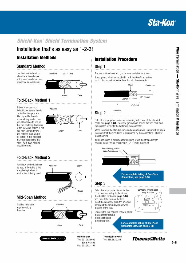
United States
Tel: 901.252.8000 800.816.7809Fax: 901.252.1354
Technical Services
Tel: 888.862.3289www.tnb.com
G-81
Shield-Kon ® Shield Termination System
Wire Term
ination — Sta-Kon
® Wire Term
ination & Insulation
Installation that’s as easy as 1-2-3!
Mid-Span Method
Enables installation anywhere along the cable.
Insulation
Shield Cable
Insulation
Shield Cable
7⁄16" (11mm)
7⁄16" (11mm)
Standard Method
Use the standard method when the shielded cable or the inner conductors are embedded in a dielectric.
Fold-Back Method 1
If there is no common dielectric for several interior cables but the gaps are filled by textile threads or something similar, care should be taken to ensure that the insulating thick ness of the individual cables is not less than .38mm for PVC, and not less than .25mm for Teflon. If this insulation thickness falls below this value, Fold-Back Method 1 should be used.
Fold-Back Method 2
Fold-Back Method 2 should be used if the cable shield is applied spirally or if a foil shield is being used.
Installation Methods Installation Procedure
Connector opening faces away from tool
Step 3
Select the appropriate die set for the crimp tool, according to the size of the shielded cable (see page G-80) and mount the dies on the tool. Insert the connector (with the shielded cable and the ground wire) between the dies of the tool.
Squeeze the tool handles firmly to crimp the connector around the shielding and the ground wire.
Shield Conductors
Jacket
Insulation
1⁄4" (6mm)
Butt insulating jackets against metal edge
Insulation
Shield Cable
Insulation
Shield
Cable
Step 1Prepare shielded wire and ground wire insulation as shown.
If two ground wires are required in a Shield-Kon® connection, twist both conductors before insertion into the connector.
Step 2
Select the appropriate connector according to the size of the shielded cable (see page G-80). Place the ground wire around the trap hook and the shielded wire into the bottom of the connector.
When inserting the shielded cable and grounding wire, care must be taken to ensure that their insulation is overlapped by the connector’s Polyester insulation film.
100% insulation is possible after crimping when the stripped length of outer jacket (visible shielding) is 7⁄16" (11mm) maximum.
For a complete listing of One-Piece
Connectors, see page G-80.
For a complete listing of One-Piece
Connector Dies, see page G-80.
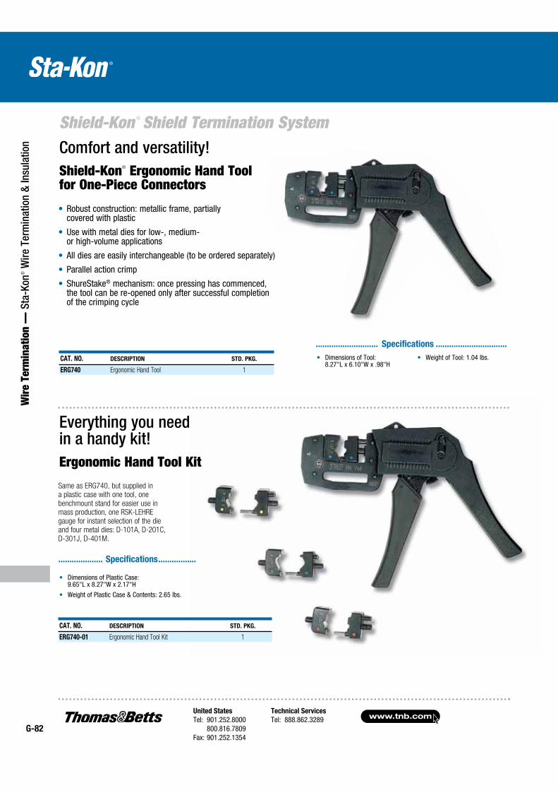
www.tnb.comUnited States
Tel: 901.252.8000 800.816.7809Fax: 901.252.1354
Technical Services
Tel: 888.862.3289G-82
Shield-Kon ® Shield Termination System
Wir
e Te
rmin
atio
n —
Sta
-Kon
® W
ire T
erm
inat
ion
& In
sula
tion
Robust construction: metallic frame, partially covered with plastic
Use with metal dies for low-, medium- or high-volume applications
All dies are easily interchangeable (to be ordered separately)
Parallel action crimp
ShureStake® mechanism: once pressing has commenced, the tool can be re-opened only after successful completion of the crimping cycle
Comfort and versatility!Shield-Kon® Ergonomic Hand Tool for One-Piece Connectors
CAT. NO. DESCRIPTION STD. PKG.
ERG740 Ergonomic Hand Tool 1
Dimensions of Tool: 8.27"L x 6.10"W x .98"H
Weight of Tool: 1.04 lbs.
............................ Specifications ................................
Everything you need in a handy kit!Ergonomic Hand Tool Kit
Dimensions of Plastic Case: 9.65"L x 8.27"W x 2.17"H
Weight of Plastic Case & Contents: 2.65 lbs.
.................... Specifications .................
CAT. NO. DESCRIPTION STD. PKG.
ERG740-01 Ergonomic Hand Tool Kit 1
Same as ERG740, but supplied in a plastic case with one tool, one benchmount stand for easier use in mass production, one RSK-LEHRE gauge for instant selection of the die and four metal dies: D-101A, D-201C, D-301J, D-401M.
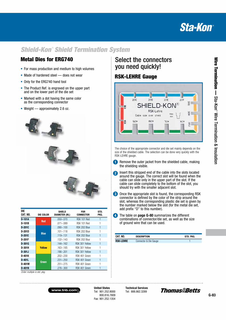
United States
Tel: 901.252.8000 800.816.7809Fax: 901.252.1354
Technical Services
Tel: 888.862.3289www.tnb.com
G-83
Shield-Kon ® Shield Termination System
Wire Term
ination — Sta-Kon
® Wire Term
ination & Insulation
Select the connectors you need quickly!RSK-LEHRE Gauge
The choice of the appropriate connector and die set mainly depends on the size of the shielded cable. The selection can be done very quickly with the RSK-LEHRE gauge.
Remove the outer jacket from the shielded cable, making the shielding visible.
Insert this stripped end of the cable into the slots located around the gauge. The correct slot will be found when the cable can slide only in the upper part of the slot. If the cable can slide completely to the bottom of the slot, you should try with the smaller adjacent slot.
Once the appropriate slot is found, the corresponding RSK connector is defined by the color of the strip around the slot, whereas the corresponding plastic die set is given by the number marked below the slot (for the metal die set, add prefix “D” to this number).
The table on page G-80 summarizes the different combinations of connector/die set, as well as the size of ground wire that can be used.
CAT. NO. DESCRIPTION STD. PKG.
RSK-LEHRE Connector & Die Gauge 1
1
2
3
4
DIE
CAT. NO. DIE COLOR
SHIELD
DIAMETER (IN.)
FOR
CONNECTOR
STD.
PKG.
D-101ARed
.050–.070 RSK 101 Red 1
D-101B .071–.089 RSK 101 Red 1
D-201C
Blue
.090–.100 RSK 202 Blue 1
D-201D .101–.118 RSK 202 Blue 1
D-201E .119–.131 RSK 202 Blue 1
D-201F .132–.143 RSK 202 Blue 1
D-301G
Yellow
.144–.162 RSK 301 Yellow 1
D-301H .163–.185 RSK 301 Yellow 1
D-301J .186–.201 RSK 301 Yellow 1
D-401K
Green
.202–.230 RSK 401 Green 1
D-401L .231–.250 RSK 401 Green 1
D-401M .251–.275 RSK 401 Green 1
D-401N .276–.300 RSK 401 Green 1
Order multiple is std. pkg.
Metal Dies for ERG740
For mass production and medium to high volumes
Made of hardened steel — does not wear
Only for the ERG740 hand tool
The Product Ref. is engraved on the upper part and on the lower part of the die set
Marked with a dot having the same color as the corresponding connector
Weight — approximately 2.6 oz.
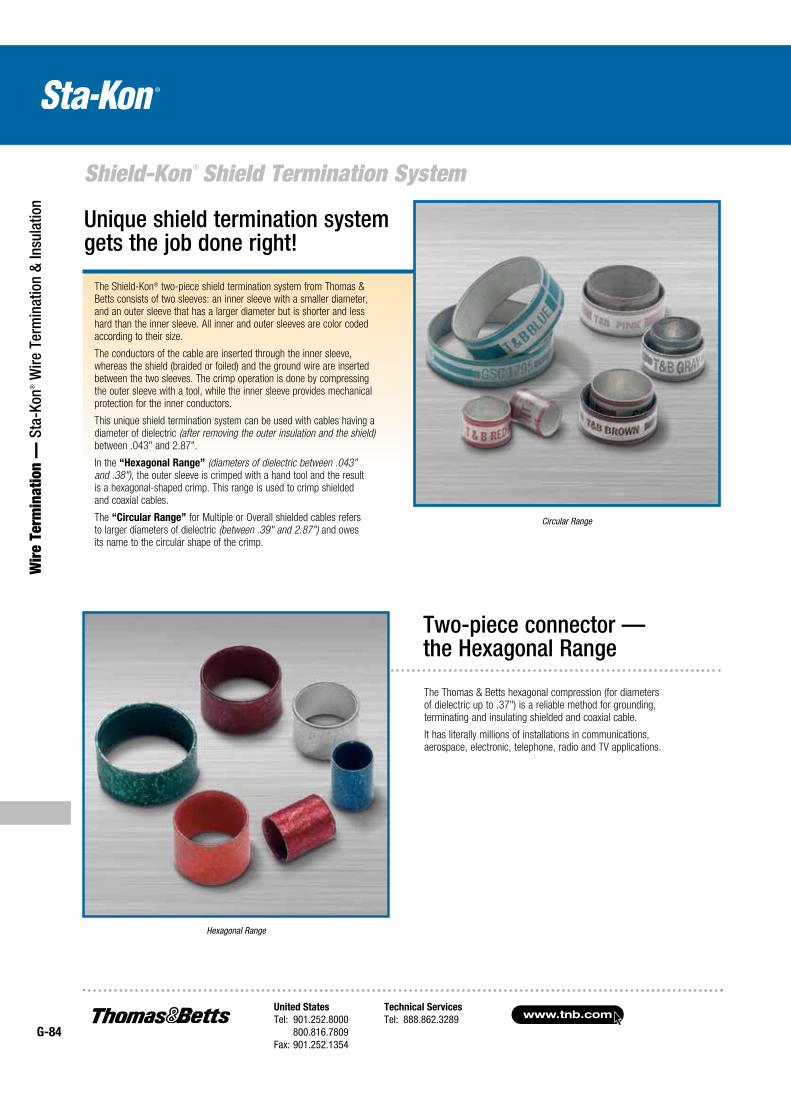
www.tnb.comUnited States
Tel: 901.252.8000 800.816.7809Fax: 901.252.1354
Technical Services
Tel: 888.862.3289G-84
Shield-Kon ® Shield Termination System
Wir
e Te
rmin
atio
n —
Sta
-Kon
® W
ire T
erm
inat
ion
& In
sula
tion
The Shield-Kon® two-piece shield termination system from Thomas & Betts consists of two sleeves: an inner sleeve with a smaller diameter, and an outer sleeve that has a larger diameter but is shorter and less hard than the inner sleeve. All inner and outer sleeves are color coded according to their size.
The conductors of the cable are inserted through the inner sleeve, whereas the shield (braided or foiled) and the ground wire are inserted between the two sleeves. The crimp operation is done by compressing the outer sleeve with a tool, while the inner sleeve provides mechanical protection for the inner conductors.
This unique shield termination system can be used with cables having a diameter of dielectric (after removing the outer insulation and the shield) between .043" and 2.87".
In the “Hexagonal Range” (diameters of dielectric between .043" and .38"), the outer sleeve is crimped with a hand tool and the result is a hexagonal-shaped crimp. This range is used to crimp shielded and coaxial cables.
The “Circular Range” for Multiple or Overall shielded cables refers to larger diameters of dielectric (between .39" and 2.87") and owes its name to the circular shape of the crimp.
Unique shield termination system gets the job done right!
Circular Range
The Thomas & Betts hexagonal compression (for diameters of dielectric up to .37") is a reliable method for grounding, terminating and insulating shielded and coaxial cable.
It has literally millions of installations in communications, aerospace, electronic, telephone, radio and TV applications.
Two-piece connector — the Hexagonal Range
Hexagonal Range
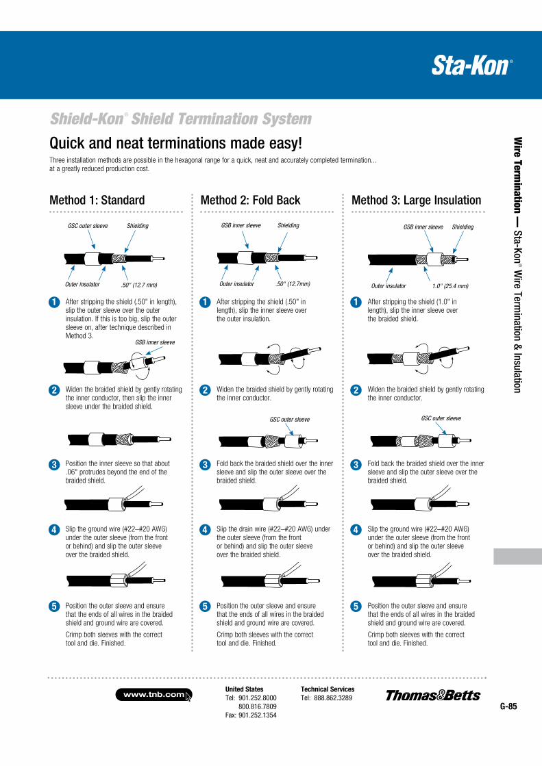
United States
Tel: 901.252.8000 800.816.7809Fax: 901.252.1354
Technical Services
Tel: 888.862.3289www.tnb.com
G-85
Shield-Kon ® Shield Termination System
Wire Term
ination — Sta-Kon
® Wire Term
ination & Insulation
Three installation methods are possible in the hexagonal range for a quick, neat and accurately completed termination... at a greatly reduced production cost.
Quick and neat terminations made easy!
GSC outer sleeve Shielding
Outer insulator .50" (12.7 mm)
GSB inner sleeve Shielding
Outer insulator .50" (12.7mm) 1.0" (25.4 mm)
GSB inner sleeve Shielding
Outer insulator
GSB inner sleeve
GSC outer sleeve GSC outer sleeve
Method 1: Standard Method 2: Fold Back Method 3: Large Insulation
After stripping the shield (.50" in length), slip the outer sleeve over the outer insulation. If this is too big, slip the outer sleeve on, after technique described in Method 3.
1 1 1 After stripping the shield (.50" in length), slip the inner sleeve over the outer insulation.
After stripping the shield (1.0" in length), slip the inner sleeve over the braided shield.
Slip the ground wire (#22–#20 AWG) under the outer sleeve (from the front or behind) and slip the outer sleeve over the braided shield.
Slip the drain wire (#22–#20 AWG) under the outer sleeve (from the front or behind) and slip the outer sleeve over the braided shield.
Slip the ground wire (#22–#20 AWG) under the outer sleeve (from the front or behind) and slip the outer sleeve over the braided shield.
Position the outer sleeve and ensure that the ends of all wires in the braided shield and ground wire are covered.
Crimp both sleeves with the correct tool and die. Finished.
Position the outer sleeve and ensure that the ends of all wires in the braided shield and ground wire are covered.
Crimp both sleeves with the correct tool and die. Finished.
Position the outer sleeve and ensure that the ends of all wires in the braided shield and ground wire are covered.
Crimp both sleeves with the correct tool and die. Finished.
Position the inner sleeve so that about .06" protrudes beyond the end of the braided shield.
Fold back the braided shield over the inner sleeve and slip the outer sleeve over the braided shield.
Fold back the braided shield over the inner sleeve and slip the outer sleeve over the braided shield.
Widen the braided shield by gently rotating the inner conductor, then slip the inner sleeve under the braided shield.
Widen the braided shield by gently rotating the inner conductor.
Widen the braided shield by gently rotating the inner conductor.
2 2 2
3 3 3
4 4 4
5 5 5
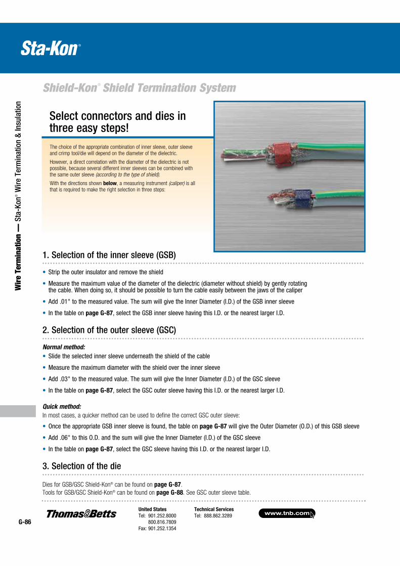
www.tnb.comUnited States
Tel: 901.252.8000 800.816.7809Fax: 901.252.1354
Technical Services
Tel: 888.862.3289G-86
Shield-Kon ® Shield Termination System
Wir
e Te
rmin
atio
n —
Sta
-Kon
® W
ire T
erm
inat
ion
& In
sula
tion
The choice of the appropriate combination of inner sleeve, outer sleeve and crimp tool/die will depend on the diameter of the dielectric.
However, a direct correlation with the diameter of the dielectric is not possible, because several different inner sleeves can be combined with the same outer sleeve (according to the type of shield).
With the directions shown below, a measuring instrument (caliper) is all that is required to make the right selection in three steps:
Select connectors and dies in three easy steps!
2. Selection of the outer sleeve (GSC)
Normal method:
Slide the selected inner sleeve underneath the shield of the cable
Measure the maximum diameter with the shield over the inner sleeve
Add .03" to the measured value. The sum will give the Inner Diameter (I.D.) of the GSC sleeve
In the table on page G-87, select the GSC outer sleeve having this I.D. or the nearest larger I.D.
Quick method:
In most cases, a quicker method can be used to define the correct GSC outer sleeve:
Once the appropriate GSB inner sleeve is found, the table on page G-87 will give the Outer Diameter (O.D.) of this GSB sleeve
Add .06" to this O.D. and the sum will give the Inner Diameter (I.D.) of the GSC sleeve
In the table on page G-87, select the GSC sleeve having this I.D. or the nearest larger I.D.
3. Selection of the die
Dies for GSB/GSC Shield-Kon® can be found on page G-87.
Tools for GSB/GSC Shield-Kon® can be found on page G-88. See GSC outer sleeve table.
1. Selection of the inner sleeve (GSB)
Strip the outer insulator and remove the shield
Measure the maximum value of the diameter of the dielectric (diameter without shield) by gently rotating the cable. When doing so, it should be possible to turn the cable easily between the jaws of the caliper
Add .01" to the measured value. The sum will give the Inner Diameter (I.D.) of the GSB inner sleeve
In the table on page G-87, select the GSB inner sleeve having this I.D. or the nearest larger I.D.
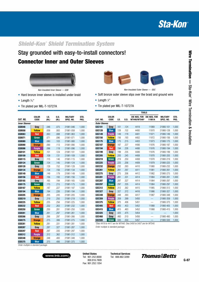
United States
Tel: 901.252.8000 800.816.7809Fax: 901.252.1354
Technical Services
Tel: 888.862.3289www.tnb.com
G-87
Shield-Kon ® Shield Termination System
Wire Term
ination — Sta-Kon
® Wire Term
ination & Insulation
Stay grounded with easy-to-install connectors!
Connector Inner and Outer Sleeves
CAT. NO.I.D.
(IN.)
O.D.
(IN.)
MILITARY
SPEC. NO.
STD.
PKG.
COLOR
CODE
Inner Sleeves
GSB046 Gray .046 .075 21981-046 1,000
GSB058 Yellow .058 .083 21981-058 1,000
GSB063 Red .063 .088 21981-063 1,000
GSB071 Green .071 .096 21981-071 1,000
GSB080 Blue .080 .103 21981-080 1,000
GSB090 Orange .090 .113 21981-090 1,000
GSB096 Purple .096 .119 21981-096 1,000
GSB101 Yellow .101 .124 21981-101 1,000
GSB109 Red .109 .131 21981-109 1,000
GSB115 Gray .115 .146 21981-115 1,000
GSB124 Green .124 .145 21981-124 1,000
GSB128 Gray .128 .152 21981-128 1,000
GSB134 Orange .134 .156 21981-134 1,000
GSB149 Blue .149 .179 21981-149 1,000
GSB156 Red .156 .193 21981-156 1,000
GSB165 Gray .165 .194 21981-165 1,000
GSB175 Green .175 .215 21981-175 1,000
GSB187 Yellow .187 .227 21981-187 1,000
GSB194 Blue .194 .226 21981-194 1,000
GSB205 Orange .205 .245 21981-205 1,000
GSB219 Gray .219 .250 21981-219 1,000
GSB225 Yellow .225 .256 21981-225 1,000
GSB232 Red .232 .263 21981-232 1,000
GSB250 Green .250 .281 21981-250 1,000
GSB261 Blue .261 .297 21981-261 1,000
GSB266 Gray .266 .297 21981-266 1,000
GSB275 Orange .275 .306 21981-275 1,000
GSB281 Yellow .281 .331 21981-281 1,000
GSB287 Gray .287 .327 21981-287 1,000
GSB297 Red .297 .335 21981-297 1,000
GSB312 Purple .312 .362 21981-312 1,000
GSB348 Orange .348 .400 21981-348 1,000
GSB375 Blue .375 .406 21981-375 1,000
Order multiple is standard package.
Non-Insulated Inner Sleeve — GSB
Hard bronze inner sleeve is installed under braid
Length 5⁄16"
Tin plated per MIL-T-10727A
Soft bronze outer sleeve slips over the braid and ground wire
Length 1⁄4"
Tin plated per MIL-T-10727A
Non-Insulated Outer Sleeve — GSC
CAT. NO.
COLOR
CODE I.D. O.D.
TOOLS
MILITARY
SPEC. NO.
STD.
PKG.
DIE NOS. FOR
WT440/WT540*
DIE NOS. FOR
11901A
Outer Sleeves
GSC101 Gray .101 .124 4419 11989 21980-101 1,000
GSC128 Blue .128 .152 4400 11970 21980-128 1,000
GSC149 Purple .149 .179 4401 11971 21980-149 1,000
GSC156 Yellow .156 .193 4402 11972 21980-156 1,000
GSC175 Blue .175 .215 4403 11973 21980-175 1,000
GSC187 Orange .187 .227 4406 11976 21980-187 1,000
GSC194 Red .194 .226 4406 11976 21980-194 1,000
GSC199 Gray .199 .235 4406 11976 21980-199 1,000
GSC205 Yellow .205 .245 4408 11978 21980-205 1,000
GSC219 Green .219 .250 4408 11978 21980-219 1,000
GSC225 Purple .225 .256 4409 11979 21980-225 1,000
GSC232 Orange .232 .263 4410 11980 21980-232 1,000
GSC261 Yellow .261 .297 4411 11981 21980-261 1,000
GSC275 Gray .275 .306 4412 11982 21980-275 1,000
GSC281 Purple .281 .331 4414 11984 21980-281 1,000
GSC287 Blue .287 .327 4414 11984 21980-287 1,000
GSC297 Green .297 .335 4414 11984 21980-297 1,000
GSC312 Yellow .312 .362 4415 11985 21980-312 1,000
GSC327 Gray .327 .372 4416 11986 21980-327 1,000
GSC348 Orange .348 .393 4417 11987 21980-348 1,000
GSC359 Purple .359 .399 5450 — 21980-359 1,000
GSC375 Yellow .375 .406 5451 — 21980-375 1,000
GSC405 Red .405 .453 5452 11988 21980-405 1,000
GSC415 Blue .415 .463 5452 11988 21980-415 1,000
GSC425 Gray .425 .475 5454 — — 1,000
GSC460 Gray .460 .510 5456 — 21980-460 1,000
GSC500 Green .500 .550 5457 — 21980-500 1,000
*Dies 4419 to 4417 are for WT440. Dies 5450 to 5457 are for WT540.
Order multiple is standard package.
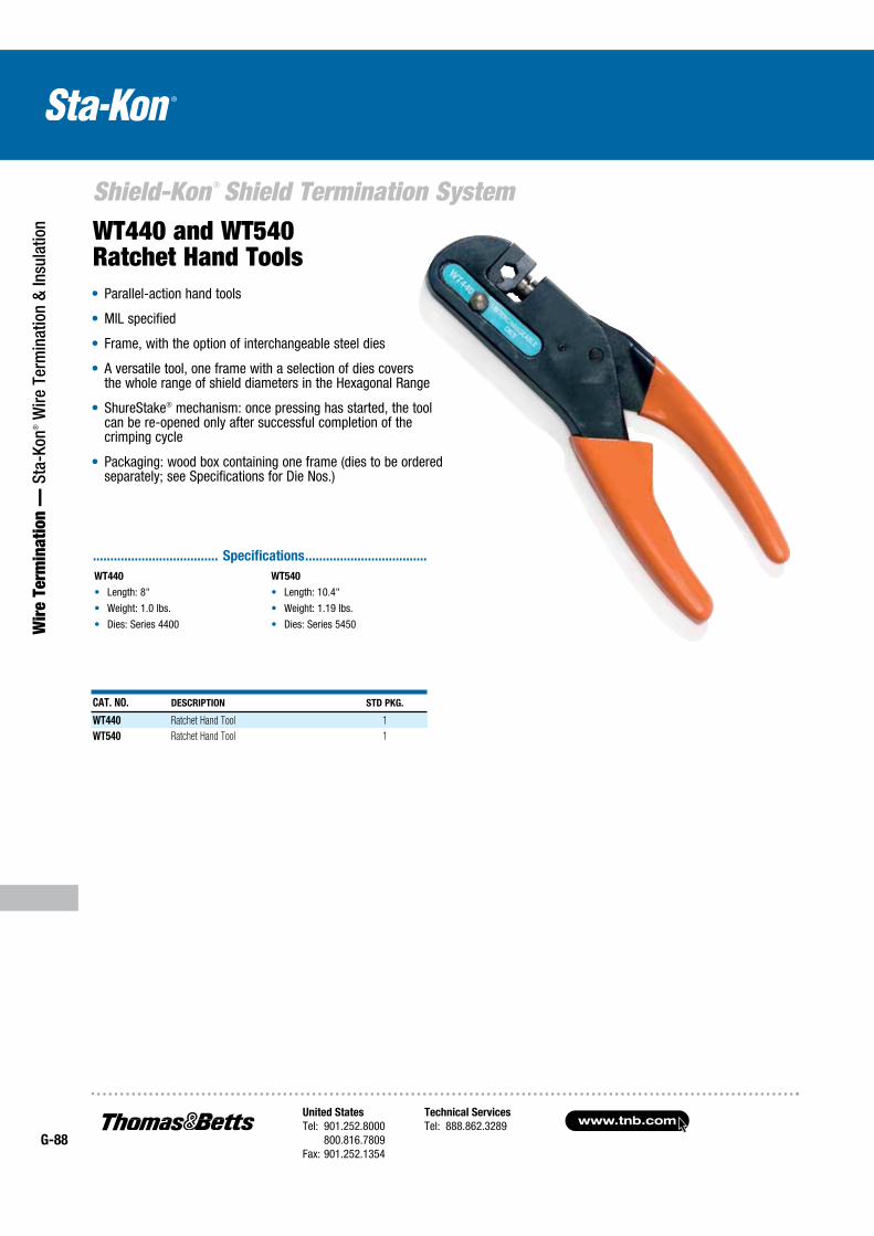
www.tnb.comUnited States
Tel: 901.252.8000 800.816.7809Fax: 901.252.1354
Technical Services
Tel: 888.862.3289G-88
Shield-Kon ® Shield Termination System
Wir
e Te
rmin
atio
n —
Sta
-Kon
® W
ire T
erm
inat
ion
& In
sula
tion
.................................... Specifications ...................................
WT440
Length: 8"
Weight: 1.0 lbs.
Dies: Series 4400
WT540
Length: 10.4"
Weight: 1.19 lbs.
Dies: Series 5450
WT440 and WT540 Ratchet Hand Tools Parallel-action hand tools
MIL specified
Frame, with the option of interchangeable steel dies
A versatile tool, one frame with a selection of dies covers the whole range of shield diameters in the Hexagonal Range
ShureStake® mechanism: once pressing has started, the tool can be re-opened only after successful completion of the crimping cycle
Packaging: wood box containing one frame (dies to be ordered separately; see Specifications for Die Nos.)
CAT. NO. DESCRIPTION STD PKG.
WT440 Ratchet Hand Tool 1
WT540 Ratchet Hand Tool 1
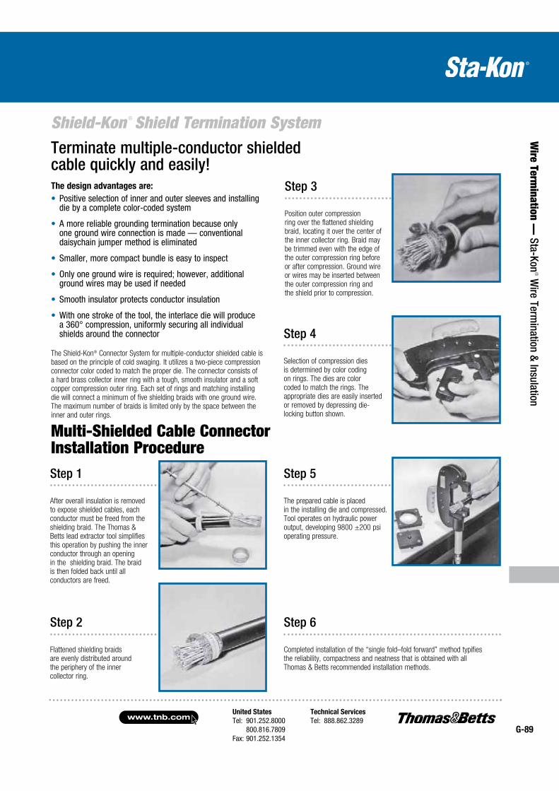
United States
Tel: 901.252.8000 800.816.7809Fax: 901.252.1354
Technical Services
Tel: 888.862.3289www.tnb.com
G-89
Shield-Kon ® Shield Termination System
Wire Term
ination — Sta-Kon
® Wire Term
ination & Insulation
The design advantages are:
Positive selection of inner and outer sleeves and installing die by a complete color-coded system
A more reliable grounding termination because only one ground wire connection is made — conventional daisychain jumper method is eliminated
Smaller, more compact bundle is easy to inspect
Only one ground wire is required; however, additional ground wires may be used if needed
Smooth insulator protects conductor insulation
With one stroke of the tool, the interlace die will produce a 360° compression, uniformly securing all individual shields around the connector
The Shield-Kon® Connector System for multiple-conductor shielded cable is based on the principle of cold swaging. It utilizes a two-piece compression connector color coded to match the proper die. The connector consists of a hard brass collector inner ring with a tough, smooth insulator and a soft copper compression outer ring. Each set of rings and matching installing die will connect a minimum of five shielding braids with one ground wire. The maximum number of braids is limited only by the space between the inner and outer rings.
Step 1
After overall insulation is removed to expose shielded cables, each conductor must be freed from the shielding braid. The Thomas & Betts lead extractor tool simplifies this operation by pushing the inner conductor through an opening in the shielding braid. The braid is then folded back until all conductors are freed.
Step 2
Flattened shielding braids are evenly distributed around the periphery of the inner collector ring.
Step 3
Position outer compression ring over the flattened shielding braid, locating it over the center of the inner collector ring. Braid may be trimmed even with the edge of the outer compression ring before or after compression. Ground wire or wires may be inserted between the outer compression ring and the shield prior to compression.
Step 4
Selection of compression dies is determined by color coding on rings. The dies are color coded to match the rings. The appropriate dies are easily inserted or removed by depressing die-locking button shown.
Step 5
The prepared cable is placed in the installing die and compressed. Tool operates on hydraulic power output, developing 9800 ±200 psi operating pressure.
Step 6
Completed installation of the “single fold–fold forward” method typifies the reliability, compactness and neatness that is obtained with all Thomas & Betts recommended installation methods.
Multi-Shielded Cable Connector Installation Procedure
Terminate multiple-conductor shielded cable quickly and easily!
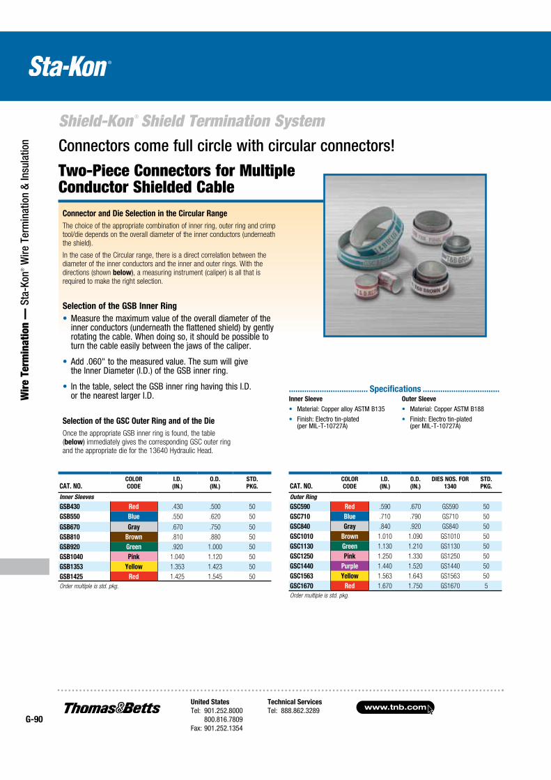
www.tnb.comUnited States
Tel: 901.252.8000 800.816.7809Fax: 901.252.1354
Technical Services
Tel: 888.862.3289G-90
Shield-Kon ® Shield Termination System
Wir
e Te
rmin
atio
n —
Sta
-Kon
® W
ire T
erm
inat
ion
& In
sula
tion
Two-Piece Connectors for Multiple Conductor Shielded Cable
Connector and Die Selection in the Circular Range
The choice of the appropriate combination of inner ring, outer ring and crimp tool/die depends on the overall diameter of the inner conductors (underneath the shield).
In the case of the Circular range, there is a direct correlation between the diameter of the inner conductors and the inner and outer rings. With the directions (shown below), a measuring instrument (caliper) is all that is required to make the right selection.
Selection of the GSB Inner Ring
Measure the maximum value of the overall diameter of the inner conductors (underneath the flattened shield) by gently rotating the cable. When doing so, it should be possible to turn the cable easily between the jaws of the caliper.
Add .060" to the measured value. The sum will give the Inner Diameter (I.D.) of the GSB inner ring.
In the table, select the GSB inner ring having this I.D. or the nearest larger I.D.
Selection of the GSC Outer Ring and of the Die
Once the appropriate GSB inner ring is found, the table (below) immediately gives the corresponding GSC outer ring and the appropriate die for the 13640 Hydraulic Head.
Connectors come full circle with circular connectors!
CAT. NO.COLOR
CODE
I.D.
(IN.)
O.D.
(IN.)
STD.
PKG.
Inner Sleeves
GSB430 Red .430 .500 50
GSB550 Blue .550 .620 50
GSB670 Gray .670 .750 50
GSB810 Brown .810 .880 50
GSB920 Green .920 1.000 50
GSB1040 Pink 1.040 1.120 50
GSB1353 Yellow 1.353 1.423 50
GSB1425 Red 1.425 1.545 50
Order multiple is std. pkg.
CAT. NO.COLOR
CODE
I.D.
(IN.)
O.D.
(IN.)
DIES NOS. FOR
1340
STD.
PKG.
Outer Ring
GSC590 Red .590 .670 GS590 50
GSC710 Blue .710 .790 GS710 50
GSC840 Gray .840 .920 GS840 50
GSC1010 Brown 1.010 1.090 GS1010 50
GSC1130 Green 1.130 1.210 GS1130 50
GSC1250 Pink 1.250 1.330 GS1250 50
GSC1440 Purple 1.440 1.520 GS1440 50
GSC1563 Yellow 1.563 1.643 GS1563 50
GSC1670 Red 1.670 1.750 GS1670 5
Order multiple is std. pkg.
Inner Sleeve
Material: Copper alloy ASTM B135
Finish: Electro tin-plated (per MIL-T-10727A)
Outer Sleeve
Material: Copper ASTM B188
Finish: Electro tin-plated (per MIL-T-10727A)
.................................... Specifications ...................................
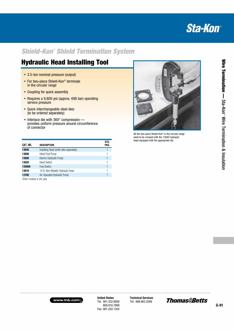
United States
Tel: 901.252.8000 800.816.7809Fax: 901.252.1354
Technical Services
Tel: 888.862.3289www.tnb.com
G-91
Shield-Kon ® Shield Termination System
Wire Term
ination — Sta-Kon
® Wire Term
ination & Insulation
Hydraulic Head Installing Tool
CAT. NO. DESCRIPTION
STD.
PKG.
13640 Installing Head (order dies separately) 1
13606 Hand-Foot Pump 1
13600 Electric Hydraulic Pump 1
13620 Hand Switch 1
13589A Foot Switch 1
13619 10-ft. Non-Metallic Hydraulic Hose 1
13760 Air-Operated Hydraulic Pump 1
Order multiple is std. pkg.
All the two-piece Shield-Kon® in the circular range need to be crimped with the 13640 hydraulic head equipped with the appropriate die.
3.5-ton nominal pressure (output)
For two-piece Shield-Kon® terminals in the circular range
Coupling for quick assembly
Requires a 9,800-psi (approx. 690 bar) operating service pressure
Quick interchangeable steel dies (to be ordered separately)
Interlace die with 360° compression — provides uniform pressure around circumference of connector
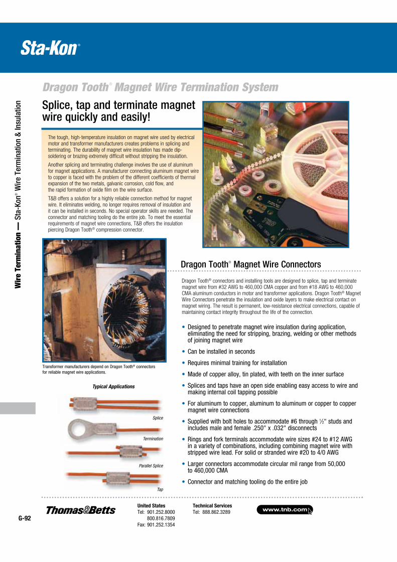
www.tnb.comUnited States
Tel: 901.252.8000 800.816.7809Fax: 901.252.1354
Technical Services
Tel: 888.862.3289G-92
Dragon Tooth ® Magnet Wire Termination System
Wir
e Te
rmin
atio
n —
Sta
-Kon
® W
ire T
erm
inat
ion
& In
sula
tion
The tough, high-temperature insulation on magnet wire used by electrical motor and transformer manufacturers creates problems in splicing and terminating. The durability of magnet wire insulation has made dip-soldering or brazing extremely difficult without stripping the insulation.
Another splicing and terminating challenge involves the use of aluminum for magnet applications. A manufacturer connecting aluminum magnet wire to copper is faced with the problem of the different coefficients of thermal expansion of the two metals, galvanic corrosion, cold flow, and the rapid formation of oxide film on the wire surface.
T&B offers a solution for a highly reliable connection method for magnet wire. It eliminates welding, no longer requires removal of insulation and it can be installed in seconds. No special operator skills are needed. The connector and matching tooling do the entire job. To meet the essential requirements of magnet wire connections, T&B offers the insulation piercing Dragon Tooth® compression connector.
Splice, tap and terminate magnet wire quickly and easily!
Dragon Tooth® Magnet Wire Connectors
Dragon Tooth® connectors and installing tools are designed to splice, tap and terminate magnet wire from #32 AWG to 460,000 CMA copper and from #18 AWG to 460,000 CMA aluminum conductors in motor and transformer applications. Dragon Tooth® Magnet Wire Connectors penetrate the insulation and oxide layers to make electrical contact on magnet wiring. The result is permanent, low-resistance electrical connections, capable of maintaining contact integrity throughout the life of the connection.
Designed to penetrate magnet wire insulation during application, eliminating the need for stripping, brazing, welding or other methods of joining magnet wire
Can be installed in seconds
Requires minimal training for installation
Made of copper alloy, tin plated, with teeth on the inner surface
Splices and taps have an open side enabling easy access to wire and making internal coil tapping possible
For aluminum to copper, aluminum to aluminum or copper to copper magnet wire connections
Supplied with bolt holes to accommodate #6 through 1⁄2" studs and includes male and female .250" x .032" disconnects
Rings and fork terminals accommodate wire sizes #24 to #12 AWG in a variety of combinations, including combining magnet wire with stripped wire lead. For solid or stranded wire #20 to 4/0 AWG
Larger connectors accommodate circular mil range from 50,000 to 460,000 CMA
Connector and matching tooling do the entire job
Transformer manufacturers depend on Dragon Tooth® connectors for reliable magnet wire applications.
Typical Applications
Parallel Splice
Tap
Termination
Splice
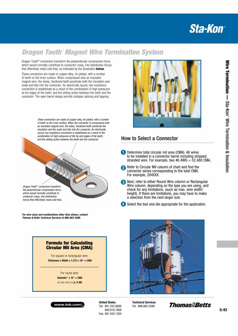
United States
Tel: 901.252.8000 800.816.7809Fax: 901.252.1354
Technical Services
Tel: 888.862.3289www.tnb.com
G-93
Dragon Tooth ® Magnet Wire Termination System
Wire Term
ination — Sta-Kon
® Wire Term
ination & Insulation
Dragon Tooth® connectors transform the perpendicular compression force, which would normally contribute to conductor creep, into distributive forces that effectively resist cold flow, as indicated by the illustration below.
These connectors are made of copper alloy, tin plated, with a number of teeth on the inner surface. When compressed onto an insulated magnet wire, the sharp, hardened teeth penetrate both the insulation and oxide and bite into the conductor. An electrically sound, low-resistance connection is established as a result of the combination of high pressures at the edges of the teeth, and the sliding action between the teeth and the conductor. The open barrel design permits midspan splicing and tapping.
How to Select a Connector
Determine total circular mil area (CMA). All wires to be installed in a connector barrel including stripped, stranded wire. For example, two #6 AWG = 52,480 CMA.
Refer to Circular Mil column of chart and find the connector series corresponding to the total CMA. For example, 204XXX.
Next, refer to either Round Wire column or Rectangular Wire column, depending on the type you are using, and check for any limitations, (such as max. wire width/height). If there are limitations, you may have to make a selection from the next larger size.
Select the tool and die appropriate for the application.
1
2
3
4
Dragon Tooth ® connectors transform the perpendicular compression force, which would normally contribute to conductor creep, into distributive forces that effectively resist cold flow.
These connectors are made of copper alloy, tin plated, with a number of teeth on the inner surface. When the connector is compressed onto an insulated magnet wire, the sharp, hardened teeth penetrate the insulation and the oxide and bite into the conductor. An electrically sound, low-resis tance connection is established as a result of the combination of high pressures at the tip and edges of the teeth, and the sliding action between the teeth and the conductor.
For wire sizes and combinations other than shown, contact
Thomas & Betts Technical Services at 888-862-3289.
For square or rectangular wire:
Thickness x Width x 1.273 x 10 6 = CMA
For round wire:
Diameter2 x 10
6 = CMA
(or see chart on p. E-88)
Formula for Calculating Circular Mil Area (CMA)
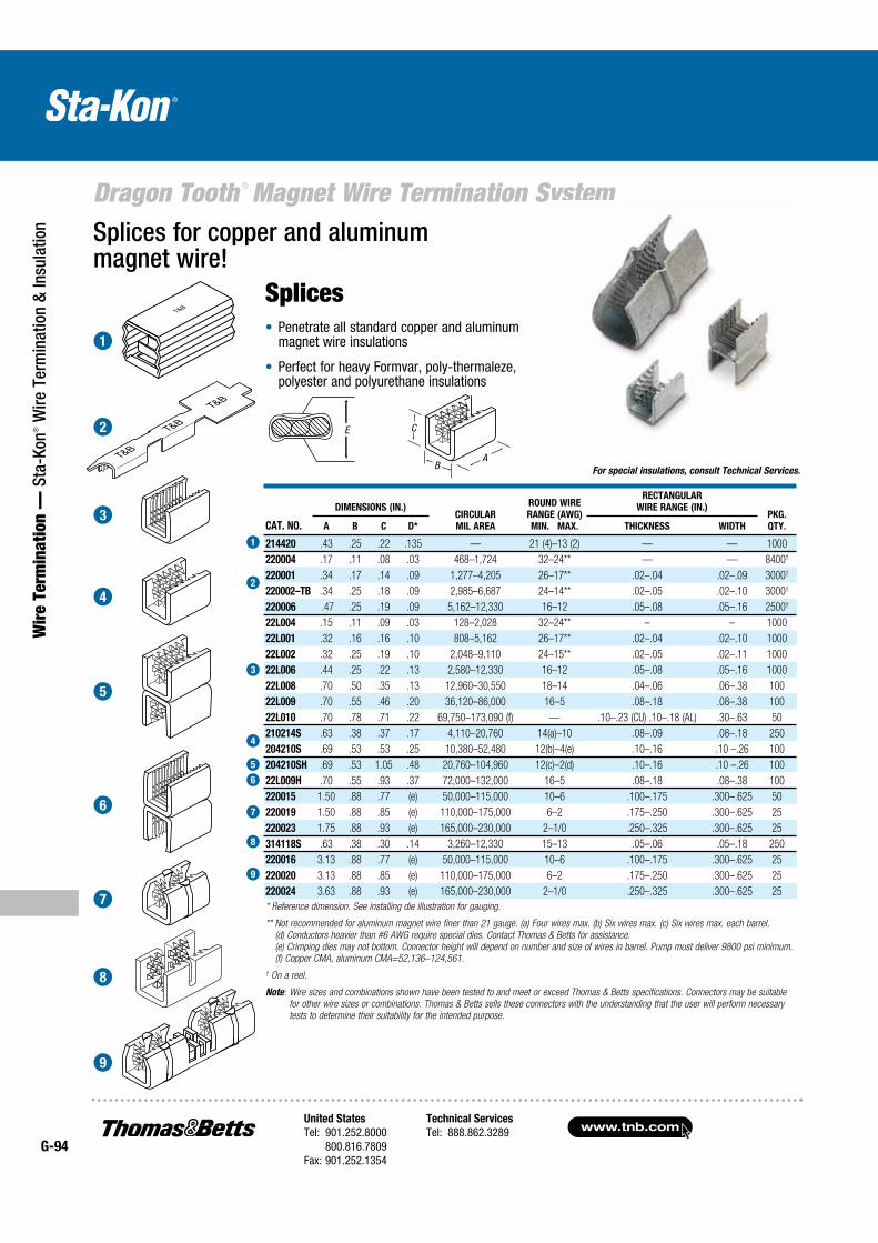
www.tnb.comUnited States
Tel: 901.252.8000 800.816.7809Fax: 901.252.1354
Technical Services
Tel: 888.862.3289G-94
Dragon Tooth ® Magnet Wire Termination System
Wir
e Te
rmin
atio
n —
Sta
-Kon
® W
ire T
erm
inat
ion
& In
sula
tion
Splices Penetrate all standard copper and aluminum magnet wire insulations
Perfect for heavy Formvar, poly-thermaleze, polyester and polyurethane insulations
CAT. NO.
DIMENSIONS (IN.)CIRCULAR
MIL AREA
ROUND WIRE
RANGE (AWG)
MIN. MAX.
RECTANGULAR
WIRE RANGE (IN.)PKG.
QTY.A B C D* THICKNESS WIDTH
214420 .43 .25 .22 .135 — 21 (4)–13 (2) — — 1000
220004 .17 .11 .08 .03 468–1,724 32–24** — — 8400†
220001 .34 .17 .14 .09 1,277–4,205 26–17** .02–.04 .02–.09 3000†
220002–TB .34 .25 .18 .09 2,985–6,687 24–14** .02–.05 .02–.10 3000†
220006 .47 .25 .19 .09 5,162–12,330 16–12 .05–.08 .05–.16 2500†
22L004 .15 .11 .09 .03 128–2,028 32–24** – – 1000
22L001 .32 .16 .16 .10 808–5,162 26–17** .02–.04 .02–.10 1000
22L002 .32 .25 .19 .10 2,048–9,110 24–15** .02–.05 .02–.11 1000
22L006 .44 .25 .22 .13 2,580–12,330 16–12 .05–.08 .05–.16 1000
22L008 .70 .50 .35 .13 12,960–30,550 18–14 .04–.06 .06–.38 100
22L009 .70 .55 .46 .20 36,120–86,000 16–5 .08–.18 .08–.38 100
22L010 .70 .78 .71 .22 69,750–173,090 (f) — .10–.23 (CU) .10–.18 (AL) .30–.63 50
210214S .63 .38 .37 .17 4,110–20,760 14(a)–10 .08–.09 .08–.18 250
204210S .69 .53 .53 .25 10,380–52,480 12(b)–4(e) .10–.16 .10 –.26 100
204210SH .69 .53 1.05 .48 20,760–104,960 12(c)–2(d) .10–.16 .10 –.26 100
22L009H .70 .55 .93 .37 72,000–132,000 16–5 .08–.18 .08–.38 100
220015 1.50 .88 .77 (e) 50,000–115,000 10–6 .100–.175 .300–.625 50
220019 1.50 .88 .85 (e) 110,000–175,000 6–2 .175–.250 .300–.625 25
220023 1.75 .88 .93 (e) 165,000–230,000 2–1/0 .250–.325 .300–.625 25
314118S .63 .38 .30 .14 3,260–12,330 15–13 .05–.06 .05–.18 250
220016 3.13 .88 .77 (e) 50,000–115,000 10–6 .100–.175 .300–.625 25
220020 3.13 .88 .85 (e) 110,000–175,000 6–2 .175–.250 .300–.625 25
220024 3.63 .88 .93 (e) 165,000–230,000 2–1/0 .250–.325 .300–.625 25
* Reference dimension. See installing die illustration for gauging.
** Not recommended for aluminum magnet wire finer than 21 gauge. (a) Four wires max. (b) Six wires max. (c) Six wires max. each barrel.
(d) Conductors heavier than #6 AWG require special dies. Contact Thomas & Betts for assistance.
(e) Crimping dies may not bottom. Connector height will depend on number and size of wires in barrel. Pump must deliver 9800 psi minimum.
(f) Copper CMA, aluminum CMA=52,136–124,561.
† On a reel.
Note: Wire sizes and combinations shown have been tested to and meet or exceed Thomas & Betts specifications. Connectors may be suitable
for other wire sizes or combinations. Thomas & Betts sells these connectors with the understanding that the user will perform necessary
tests to determine their suitability for the intended purpose.
B
C
A
E
For special insulations, consult Technical Services.
Splices for copper and aluminum magnet wire!
1
2
3
4
5
6
7
8
9
1
2
3
4
5
6
7
8
9
E C
BA
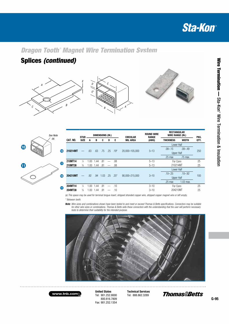
United States
Tel: 901.252.8000 800.816.7809Fax: 901.252.1354
Technical Services
Tel: 888.862.3289www.tnb.com
G-95
Dragon Tooth ® Magnet Wire Termination System
Wire Term
ination — Sta-Kon
® Wire Term
ination & Insulation
See Note (a).
B
E
C
A
(a) This space may be used for terminal tongue insert, stripped stranded copper wire, stripped copper magnet wire or left empty.
* Between teeth.
Note: Wire sizes and combinations shown have been tested to and meet or exceed Thomas & Betts specifications. Connectors may be suitable
for other wire sizes or combinations. Thomas & Betts sells these connectors with the understanding that the user will perform necessary
tests to determine their suitability for the intended purpose.
Splices (continued)
10
11
10
11
11
10
CAT. NO.STUD
SIZE
DIMENSIONS (IN.)CIRCULAR
MIL AREA
ROUND WIRE
RANGE
(AWG)
RECTANGULAR
WIRE RANGE (IN.)PKG.
QTY.A B C D E THICKNESS WIDTH
210214MT — .63 .63 .75 .25 .19* 20,000–105,000 5–13
Lower Half
250.08–.15 .08–.49
Upper Half
.25 max .75 max.
210MT14 1⁄4 1.00 1.44 .81 — .08 5–13 For Conn
210214MT
25
210MT38 3⁄8 1.00 1.44 .81 — .08 5–13 25
204210MT — .92 .94 1.03 .25 .25* 90,000–215,000 3–10
Lower Half
100.10–.25 .10–.92
Upper Half
.25 max 1.03 max.
204MT14 1⁄4 1.00 1.44 .91 — .10 3–10 For Conn
204210MT
25
204MT38 3⁄8 1.00 1.44 .91 — .10 3–10 25
B
D
E
C
A
*
C
A
B
ED
E*
B A
C
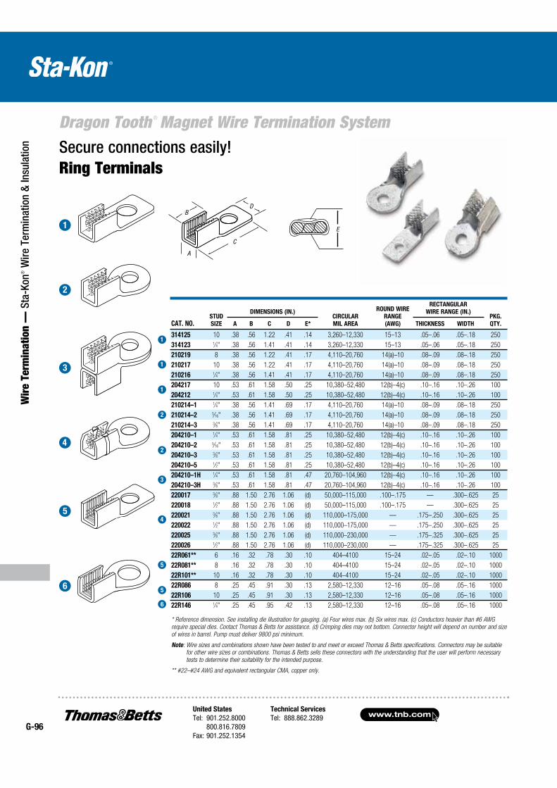
www.tnb.comUnited States
Tel: 901.252.8000 800.816.7809Fax: 901.252.1354
Technical Services
Tel: 888.862.3289G-96
Dragon Tooth ® Magnet Wire Termination System
Wir
e Te
rmin
atio
n —
Sta
-Kon
® W
ire T
erm
inat
ion
& In
sula
tion
CAT. NO.STUD
SIZE
DIMENSIONS (IN.)CIRCULAR
MIL AREA
ROUND WIRE
RANGE
(AWG)
RECTANGULAR
WIRE RANGE (IN.)PKG.
QTY.A B C D E* THICKNESS WIDTH
314125 10 .38 .56 1.22 .41 .14 3,260–12,330 15–13 .05–.06 .05–.18 250
314123 1⁄4" .38 .56 1.41 .41 .14 3,260–12,330 15–13 .05–.06 .05–.18 250
210219 8 .38 .56 1.22 .41 .17 4,110–20,760 14(a)–10 .08–.09 .08–.18 250
210217 10 .38 .56 1.22 .41 .17 4,110–20,760 14(a)–10 .08–.09 .08–.18 250
210216 1⁄4" .38 .56 1.41 .41 .17 4,110–20,760 14(a)–10 .08–.09 .08–.18 250
204217 10 .53 .61 1.58 .50 .25 10,380–52,480 12(b)–4(c) .10–.16 .10–.26 100
204212 1⁄4" .53 .61 1.58 .50 .25 10,380–52,480 12(b)–4(c) .10–.16 .10–.26 100
210214–1 1⁄4" .38 .56 1.41 .69 .17 4,110–20,760 14(a)–10 .08–.09 .08–.18 250
210214–2 5⁄16" .38 .56 1.41 .69 .17 4,110–20,760 14(a)–10 .08–.09 .08–.18 250
210214–3 3⁄8" .38 .56 1.41 .69 .17 4,110–20,760 14(a)–10 .08–.09 .08–.18 250
204210–1 1⁄4" .53 .61 1.58 .81 .25 10,380–52,480 12(b)–4(c) .10–.16 .10–.26 100
204210–2 5⁄16" .53 .61 1.58 .81 .25 10,380–52,480 12(b)–4(c) .10–.16 .10–.26 100
204210–3 3⁄8" .53 .61 1.58 .81 .25 10,380–52,480 12(b)–4(c) .10–.16 .10–.26 100
204210–5 1⁄2" .53 .61 1.58 .81 .25 10,380–52,480 12(b)–4(c) .10–.16 .10–.26 100
204210–1H 1⁄4" .53 .61 1.58 .81 .47 20,760–104,960 12(b)–4(c) .10–.16 .10–.26 100
204210–3H 3⁄8" .53 .61 1.58 .81 .47 20,760–104,960 12(b)–4(c) .10–.16 .10–.26 100
220017 3⁄8" .88 1.50 2.76 1.06 (d) 50,000–115,000 .100–.175 — .300–.625 25
220018 1⁄2" .88 1.50 2.76 1.06 (d) 50,000–115,000 .100–.175 — .300–.625 25
220021 3⁄8" .88 1.50 2.76 1.06 (d) 110,000–175,000 — .175–.250 .300–.625 25
220022 1⁄2" .88 1.50 2.76 1.06 (d) 110,000–175,000 — .175–.250 .300–.625 25
220025 3⁄8" .88 1.50 2.76 1.06 (d) 110,000–230,000 — .175–.325 .300–.625 25
220026 1⁄2" .88 1.50 2.76 1.06 (d) 110,000–230,000 — .175–.325 .300–.625 25
22R061** 6 .16 .32 .78 .30 .10 404–4100 15–24 .02–.05 .02–.10 1000
22R081** 8 .16 .32 .78 .30 .10 404–4100 15–24 .02–.05 .02–.10 1000
22R101** 10 .16 .32 .78 .30 .10 404–4100 15–24 .02–.05 .02–.10 1000
22R086 8 .25 .45 .91 .30 .13 2,580–12,330 12–16 .05–.08 .05–.16 1000
22R106 10 .25 .45 .91 .30 .13 2,580–12,330 12–16 .05–.08 .05–.16 1000
22R146 1⁄4" .25 .45 .95 .42 .13 2,580–12,330 12–16 .05–.08 .05–.16 1000
BD
C
A
E
* Reference dimension. See installing die illustration for gauging. (a) Four wires max. (b) Six wires max. (c) Conductors heavier than #6 AWG
require special dies. Contact Thomas & Betts for assistance. (d) Crimping dies may not bottom. Connector height will depend on number and size
of wires in barrel. Pump must deliver 9800 psi minimum.
Note: Wire sizes and combinations shown have been tested to and meet or exceed Thomas & Betts specifications. Connectors may be suitable
for other wire sizes or combinations. Thomas & Betts sells these connectors with the understanding that the user will perform necessary
tests to determine their suitability for the intended purpose.
** #22–#24 AWG and equivalent rectangular CMA, copper only.
Secure connections easily!Ring Terminals
1
2
3
4
5
6
1
1
1
2
2
3
4
5
5
6
A
C
BD
E
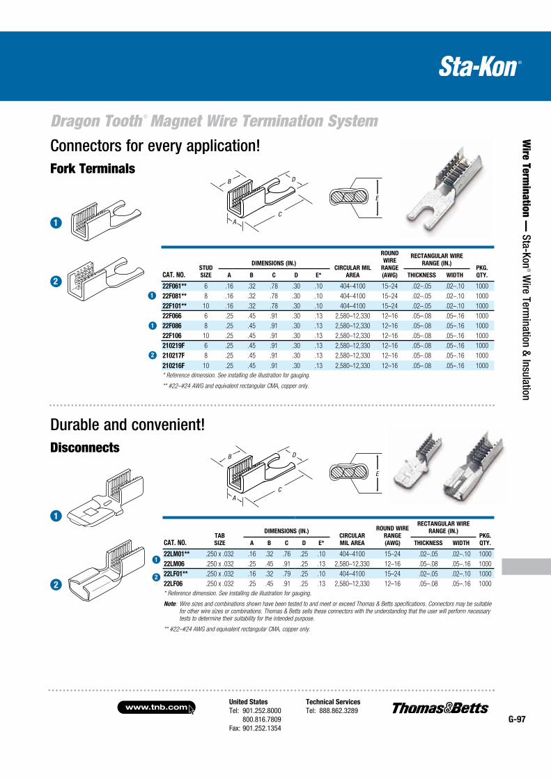
United States
Tel: 901.252.8000 800.816.7809Fax: 901.252.1354
Technical Services
Tel: 888.862.3289www.tnb.com
G-97
Dragon Tooth ® Magnet Wire Termination System
Wire Term
ination — Sta-Kon
® Wire Term
ination & Insulation
Connectors for every application!Fork Terminals
Durable and convenient!Disconnects
B D
C
A
E
B D
C
A
E
CAT. NO.STUD
SIZE
DIMENSIONS (IN.)CIRCULAR MIL
AREA
ROUND
WIRE
RANGE
(AWG)
RECTANGULAR WIRE
RANGE (IN.)PKG.
QTY.A B C D E* THICKNESS WIDTH
22F061** 6 .16 .32 .78 .30 .10 404–4100 15–24 .02–.05 .02–.10 1000
22F081** 8 .16 .32 .78 .30 .10 404–4100 15–24 .02–.05 .02–.10 1000
22F101** 10 .16 .32 .78 .30 .10 404–4100 15–24 .02–.05 .02–.10 1000
22F066 6 .25 .45 .91 .30 .13 2,580–12,330 12–16 .05–.08 .05–.16 1000
22F086 8 .25 .45 .91 .30 .13 2,580–12,330 12–16 .05–.08 .05–.16 1000
22F106 10 .25 .45 .91 .30 .13 2,580–12,330 12–16 .05–.08 .05–.16 1000
210219F 6 .25 .45 .91 .30 .13 2,580–12,330 12–16 .05–.08 .05–.16 1000
210217F 8 .25 .45 .91 .30 .13 2,580–12,330 12–16 .05–.08 .05–.16 1000
210216F 10 .25 .45 .91 .30 .13 2,580–12,330 12–16 .05–.08 .05–.16 1000
* Reference dimension. See installing die illustration for gauging.
** #22–#24 AWG and equivalent rectangular CMA, copper only.
CAT. NO.TAB
SIZE
DIMENSIONS (IN.)CIRCULAR
MIL AREA
ROUND WIRE
RANGE
(AWG)
RECTANGULAR WIRE
RANGE (IN.)PKG.
QTY.A B C D E* THICKNESS WIDTH
22LM01** .250 x .032 .16 .32 .76 .25 .10 404–4100 15–24 .02–.05 .02–.10 1000
22LM06 .250 x .032 .25 .45 .91 .25 .13 2,580–12,330 12–16 .05–.08 .05–.16 1000
22LF01** .250 x .032 .16 .32 .79 .25 .10 404–4100 15–24 .02–.05 .02–.10 1000
22LF06 .250 x .032 .25 .45 .91 .25 .13 2,580–12,330 12–16 .05–.08 .05–.16 1000
* Reference dimension. See installing die illustration for gauging.
Note: Wire sizes and combinations shown have been tested to and meet or exceed Thomas & Betts specifications. Connectors may be suitable
for other wire sizes or combinations. Thomas & Betts sells these connectors with the understanding that the user will perform necessary
tests to determine their suitability for the intended purpose.
** #22–#24 AWG and equivalent rectangular CMA, copper only.
1
2
1
2
1
1
2
1
2
A
B
C
CA
B D
E
D
E
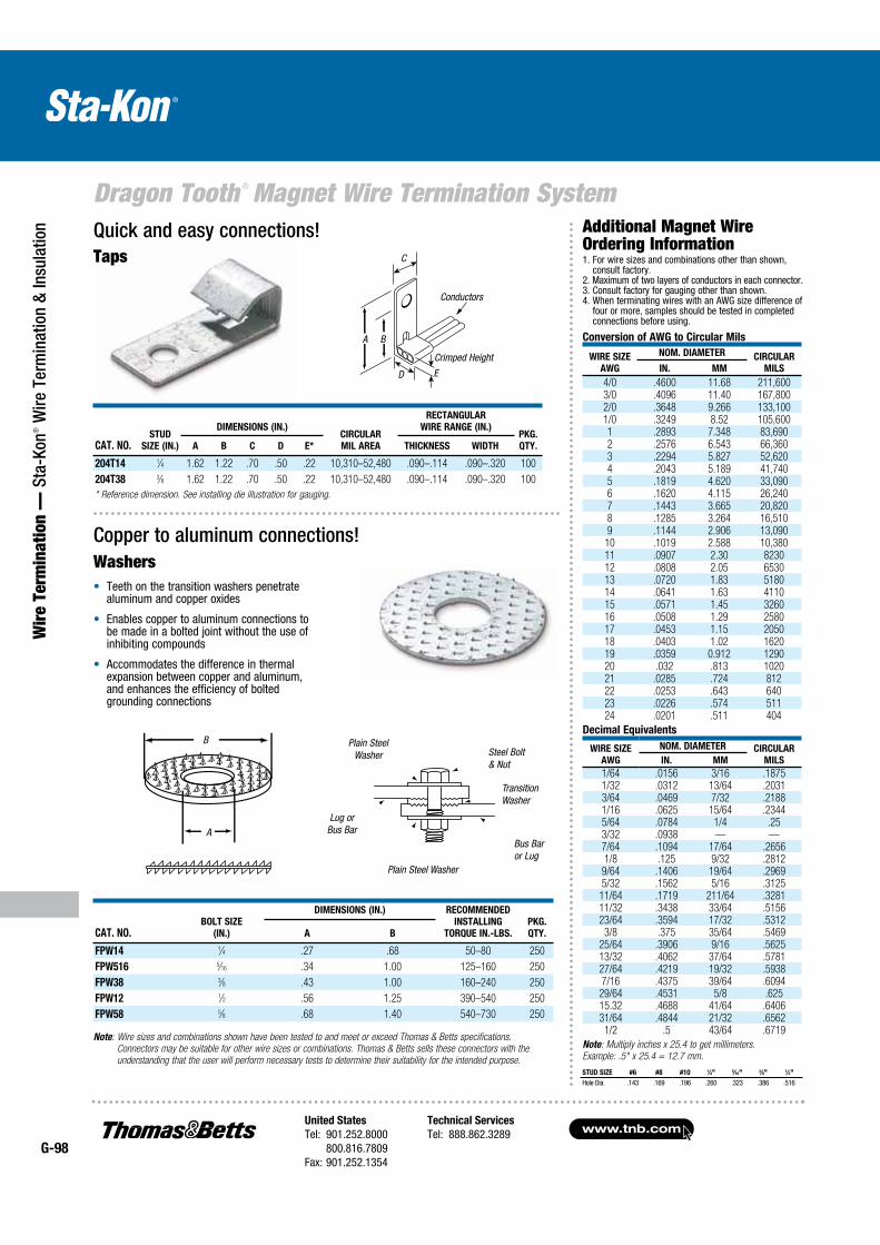
www.tnb.comUnited States
Tel: 901.252.8000 800.816.7809Fax: 901.252.1354
Technical Services
Tel: 888.862.3289G-98
Dragon Tooth ® Magnet Wire Termination System
Wir
e Te
rmin
atio
n —
Sta
-Kon
® W
ire T
erm
inat
ion
& In
sula
tion
Washers Teeth on the transition washers penetrate
aluminum and copper oxides
Enables copper to aluminum connections to be made in a bolted joint without the use of inhibiting compounds
Accommodates the difference in thermal expansion between copper and aluminum, and enhances the efficiency of bolted grounding connections
TapsQuick and easy connections!
Copper to aluminum connections!
Conductors
Crimped Height
B
D E
C
A
B
A
CAT. NO.STUD
SIZE (IN.)
DIMENSIONS (IN.)CIRCULAR
MIL AREA
RECTANGULAR
WIRE RANGE (IN.)PKG.
QTY.A B C D E* THICKNESS WIDTH
204T14 1⁄4 1.62 1.22 .70 .50 .22 10,310–52,480 .090–.114 .090–.320 100
204T38 3⁄8 1.62 1.22 .70 .50 .22 10,310–52,480 .090–.114 .090–.320 100
* Reference dimension. See installing die illustration for gauging.
CAT. NO.BOLT SIZE
(IN.)
DIMENSIONS (IN.) RECOMMENDED
INSTALLING
TORQUE IN.-LBS.
PKG.
QTY.A B
FPW14 1⁄4 .27 .68 50–80 250
FPW516 5⁄16 .34 1.00 125–160 250
FPW38 3⁄8 .43 1.00 160–240 250
FPW12 1⁄2 .56 1.25 390–540 250
FPW58 5⁄8 .68 1.40 540–730 250
WIRE SIZE
AWG
NOM. DIAMETER CIRCULAR
MILSIN. MM
4/0 .4600 11.68 211,6003/0 .4096 11.40 167,8002/0 .3648 9.266 133,1001/0 .3249 8.52 105,6001 .2893 7.348 83,6902 .2576 6.543 66,3603 .2294 5.827 52,6204 .2043 5.189 41,7405 .1819 4.620 33,0906 .1620 4.115 26,2407 .1443 3.665 20,8208 .1285 3.264 16,5109 .1144 2.906 13,090
10 .1019 2.588 10,38011 .0907 2.30 823012 .0808 2.05 653013 .0720 1.83 518014 .0641 1.63 411015 .0571 1.45 326016 .0508 1.29 258017 .0453 1.15 205018 .0403 1.02 162019 .0359 0.912 129020 .032 .813 102021 .0285 .724 81222 .0253 .643 64023 .0226 .574 51124 .0201 .511 404
WIRE SIZE
AWG
NOM. DIAMETER CIRCULAR
MILSIN. MM
1/64 .0156 3/16 .18751/32 .0312 13/64 .20313/64 .0469 7/32 .21881/16 .0625 15/64 .23445/64 .0784 1/4 .253/32 .0938 — —7/64 .1094 17/64 .26561/8 .125 9/32 .2812
9/64 .1406 19/64 .29695/32 .1562 5/16 .3125
11/64 .1719 211/64 .328111/32 .3438 33/64 .515623/64 .3594 17/32 .5312
3/8 .375 35/64 .546925/64 .3906 9/16 .562513/32 .4062 37/64 .578127/64 .4219 19/32 .59387/16 .4375 39/64 .6094
29/64 .4531 5/8 .62515.32 .4688 41/64 .640631/64 .4844 21/32 .6562
1/2 .5 43/64 .6719
Note: Multiply inches x 25.4 to get millimeters.
Example: .5" x 25.4 = 12.7 mm.
Additional Magnet Wire Ordering Information1. For wire sizes and combinations other than shown,
consult factory.2. Maximum of two layers of conductors in each connector.3. Consult factory for gauging other than shown.4. When terminating wires with an AWG size difference of
four or more, samples should be tested in completed connections before using.
Conversion of AWG to Circular Mils
Decimal Equivalents
Note: Wire sizes and combinations shown have been tested to and meet or exceed Thomas & Betts specifications.
Connectors may be suitable for other wire sizes or combinations. Thomas & Betts sells these connectors with the
understanding that the user will perform necessary tests to determine their suitability for the intended purpose.STUD SIZE #6 #8 #10 1⁄4" 5⁄16" 3⁄8" 1⁄2"
Hole Dia. .143 .169 .196 .260 .323 .386 .516
C
A
ALug or
Bus Bar
Plain Steel Washer Steel Bolt
& Nut
Transition Washer
Bus Bar or Lug
Plain Steel Washer
B
B
D E
Crimped Height
Conductors
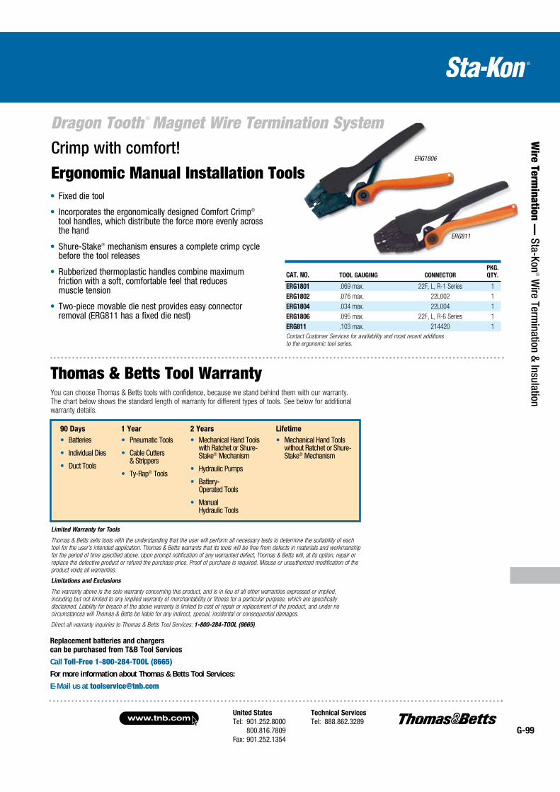
United States
Tel: 901.252.8000 800.816.7809Fax: 901.252.1354
Technical Services
Tel: 888.862.3289www.tnb.com
G-99
Dragon Tooth ® Magnet Wire Termination System
Wire Term
ination — Sta-Kon
® Wire Term
ination & Insulation
Crimp with comfort!
Ergonomic Manual Installation Tools
CAT. NO. TOOL GAUGING CONNECTOR
PKG.
QTY.
ERG1801 .069 max. 22F, L, R-1 Series 1
ERG1802 .076 max. 22L002 1
ERG1804 .034 max. 22L004 1
ERG1806 .095 max. 22F, L, R-6 Series 1
ERG811 .103 max. 214420 1
Contact Customer Services for availability and most recent additions
to the ergonomic tool series.
ERG1806
ERG811
Fixed die tool
Incorporates the ergonomically designed Comfort Crimp® tool handles, which distribute the force more evenly across the hand
Shure-Stake® mechanism ensures a complete crimp cycle before the tool releases
Rubberized thermoplastic handles combine maximum friction with a soft, comfortable feel that reduces muscle tension
Two-piece movable die nest provides easy connector removal (ERG811 has a fixed die nest)
Limited Warranty for Tools
Thomas & Betts sells tools with the understanding that the user will perform all necessary tests to determine the suitability of each
tool for the user’s intended application. Thomas & Betts warrants that its tools will be free from defects in materials and workmanship
for the period of time specified above. Upon prompt notification of any warranted defect, Thomas & Betts will, at its option, repair or
replace the defective product or refund the purchase price. Proof of purchase is required. Misuse or unauthorized modification of the
product voids all warranties.
Limitations and Exclusions
The warranty above is the sole warranty concerning this product, and is in lieu of all other warranties expressed or implied,
including but not limited to any implied warranty of merchantability or fitness for a particular purpose, which are specifically
disclaimed. Liability for breach of the above warranty is limited to cost of repair or replacement of the product, and under no
circumstances will Thomas & Betts be liable for any indirect, special, incidental or consequential damages.
Direct all warranty inquiries to Thomas & Betts Tool Services: 1-800-284-TOOL (8665).
Thomas & Betts Tool WarrantyYou can choose Thomas & Betts tools with confidence, because we stand behind them with our warranty. The chart below shows the standard length of warranty for different types of tools. See below for additional warranty details.
Replacement batteries and chargers
can be purchased from T&B Tool Services
Call Toll-Free 1-800-284-TOOL (8665)
For more information about Thomas & Betts Tool Services:
E-Mail us at [email protected]
90 Days
Batteries
Individual Dies
Duct Tools
1 Year
Pneumatic Tools
Cable Cutters & Strippers
Ty-Rap® Tools
2 Years
Mechanical Hand Tools with Ratchet or Shure-Stake® Mechanism
Hydraulic Pumps
Battery- Operated Tools
Manual Hydraulic Tools
Lifetime
Mechanical Hand Tools without Ratchet or Shure-Stake® Mechanism

www.tnb.comUnited States
Tel: 901.252.8000 800.816.7809Fax: 901.252.1354
Technical Services
Tel: 888.862.3289G-100
Dragon Tooth ® Magnet Wire Termination System
Wir
e Te
rmin
atio
n —
Sta
-Kon
® W
ire T
erm
inat
ion
& In
sula
tion
Interchangeable dies can be quickly changed to crimp non-insulated and insulated terminals up to #6 AWG
Dies are the same as our hand tools — crimps will be exactly the same between Dragon Tooth® hand tools such as our ERG1804 and the BAT22-6
360° rotating head gives the user the added flexibility when crimping hard-to-reach connections
Short cycle time equates to crimping times of less than two seconds
Quick, lightweight, and maneuverable
NiCd battery operation provides long-lasting battery life to complete up to 150 crimps on a single charge
Extra battery and charger are included with the tool, ensuring round-the-clock operation
Battery charger provides full battery life in under an hour
Linear crimping motion gives a symmetric, high-quality crimp every time
Battery-Powered Crimping Tool —BAT22-6
11⁄2 tons of grip that weighs less than three pounds!
CAT. NO. DESCRIPTION
PKG.
QTY.
BAT22-6 Battery Crimping Tool 1.5 Ton with 120VAC Charger 1
Crimp Dies*
DIE1801 22 F, L, R-1 Series 1
DIE1802 22L002 1
DIE1804 22L004 1
DIE1806 22 F,L,R-6 Series 1
Tool purchase includes crimping tool, two 9V batteries, charger and case.
* Dies sold separately.
Easy to rotate with your wrist — delivers fast and effective crimping power.
T&B’s newest battery-powered tool is fast and portable for making high-volume and difficult-to-reach terminal installations in a snap. The BAT22-6 delivers 1.5 tons of crimping force with an easy, pushbutton trigger. The lightweight, ergonomic design minimizes the risk of repetitive motion injuries that can occur with traditional hand crimping tools. And at less than three pounds, one-hand operation is easy while still packing enough power to crimp up to #6 AWG terminals in seconds.
Included Accessories
Sturdy, plastic carrying case for portability
Two 9.6V NiCd batteries and battery charger
Sturdy tray for convenient storage of crimp dies
Uses the exact dies of the Comfort Crimp® line of ergonomic tools for Sta-Kon® and Dragon Tooth® Connectors.
Crimping Force: 2,900 lbs. max.
Wire Crimping Range: Up to #6 AWG
Crimp Cycle Time: 2 seconds
Power Supply: 9.6V NiCd battery
Recharging Time: 1 hour
Crimps per Charge: 150
Dimensions: 25.4" (645mm) Length 3.1" (79mm) Width 2.1" (53mm) Height
Tool Weight (With Battery): 23⁄4 lbs.
.................................... Specifications ...................................
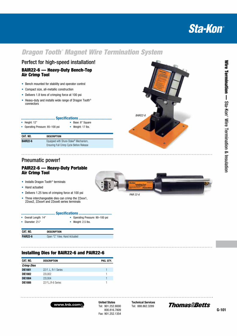
United States
Tel: 901.252.8000 800.816.7809Fax: 901.252.1354
Technical Services
Tel: 888.862.3289www.tnb.com
G-101
Dragon Tooth ® Magnet Wire Termination System
Wire Term
ination — Sta-Kon
® Wire Term
ination & Insulation
Pneumatic power!PAIR22-6 — Heavy-Duty Portable Air Crimp Tool
Installs Dragon Tooth® terminals
Hand actuated
Delivers 1.25 tons of crimping force at 100 psi
Three interchangeable dies can crimp the 22xxx1, 22xxx2, 22xxx4 and 22xxx6 series terminals
Perfect for high-speed installation!BAIR22-6 — Heavy-Duty Bench-Top Air Crimp Tool
Bench mounted for stability and operator control
Compact size, all-metallic construction
Delivers 1.8 tons of crimping force at 100 psi
Heavy-duty and installs wide range of Dragon Tooth® connectors
CAT. NO. DESCRIPTION
PAIR22-6 Open “C” Yoke; Hand Actuated
CAT. NO. DESCRIPTION
BAIR22-6 Equipped with Shure-Stake® Mechanism,
Ensuring Full Crimp Cycle Before Release
BAIR22-6
Installing Dies for BAIR22-6 and PAIR22-6
CAT. NO. DESCRIPTION PKG. QTY.
Crimp Dies
DIE1801 22 F, L, R-1 Series 1
DIE1802 22L002 1
DIE1804 22L004 1
DIE1806 22 F,L,R-6 Series 1
Height: 12"
Operating Pressure: 85–100 psi
Base: 8" Square
Weight: 17 lbs.
.................................... Specifications ...................................
Overall Length: 14"
Diameter: 21⁄4"
Operating Pressure: 90–100 psi
Weight: 2.5 lbs.
.................................... Specifications ...................................
PAIR 22-6

www.tnb.comUnited States
Tel: 901.252.8000 800.816.7809Fax: 901.252.1354
Technical Services
Tel: 888.862.3289G-102
Dragon Tooth ® Magnet Wire Termination System
Wir
e Te
rmin
atio
n —
Sta
-Kon
® W
ire T
erm
inat
ion
& In
sula
tion Rugged and portable!
6-Ton Hydraulic Head
Lightweight design—weighs less than 7 lbs. including dies
Includes steel carrying case
Tool carrying case included
Dies are ordered as a set (two pieces)
CAT. NO. DESCRIPTION
PKG.
QTY
13100A Remote 14-Ton Hydraulic Head (Dies Ordered Separately) 1
See die chart on page G-104 for complete listing of dies and connectors used with 13100A.
FORGED
STEEL
CAT. NO. DESCRIPTION
TBM6H The TBM6H Remote Hydraulic Crimping Head is a lightweight
but powerful compression tool. The TBM6H operates from any
10,000-psi hydraulic pump.
See die chart on page G-104 for complete listing of dies and connectors used with TBM6H.
CAT. NO. DESCRIPTION
PKG.
QTY.
13400 12-ton crimping tool supplied with adapter TBM12D-AR is
used for installing both insulated and non-insulated Sta-Kon®
terminals #8 AWG to 250 kcmil (dies ordered separately)
1
See die chart on page G-104 for complete listing of dies and connectors used with 13400.
Lightweight design!14-Ton Hydraulic Head
14 tons output (nominal)
10,000-psi max. hydraulic operating pressure
Weighs 10 lbs.
Powerful and reliable! 12-Ton Hydraulic Head
12 tons output (nominal)
10,000 psi max. hydraulic operating pressure
Weighs 15 lbs.
Output Force: 6 tons nominal
Operating Pressure: 10,000 psi nominal
Tool Weight: 61⁄2 lbs. (without dies)
Tool Dimensions: 131⁄2" long, 31⁄2" wide
.................................... Specifications ...................................
Output: 14 tons (nominal)
Hydraulic Operating Pressure: 10,000 psi (max.)
Length (with Coupling): 111⁄2"
Width: 21⁄2"
Height: 41⁄4"
Weight (without Dies): 10 lbs.
.................................... Specifications ...................................Output: 12 tons (nominal)
Hydraulic Operating Pressure: 10,000 psi (max.)
Length (with coupling): 141⁄2"
Width: 31⁄4"
Weight (without dies): 15 lbs.
.................................... Specifications ...................................
Military listed and 12 tons of crimping power!12-Ton Crimping Tool (Military Spec. MS25441-1)
13642M
CAT. NO. DESCRIPTION PKG. QTY.
13642M Hydraulic-operated 12-ton tool installs #8 AWG
through 250 kcmil Sta-Kon® terminals
(dies ordered separately)
1
See die chart on page G-104 for complete listing of dies and connectors used with 13642M.
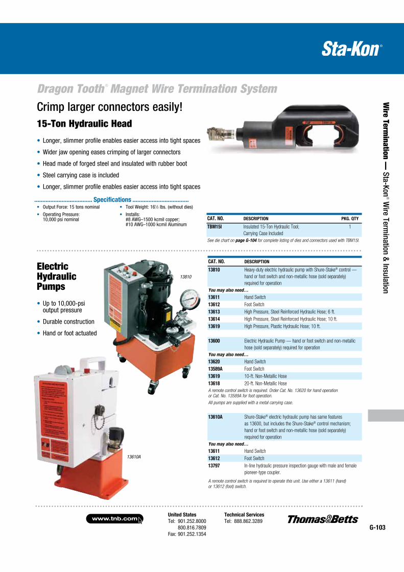
United States
Tel: 901.252.8000 800.816.7809Fax: 901.252.1354
Technical Services
Tel: 888.862.3289www.tnb.com
G-103
Dragon Tooth ® Magnet Wire Termination System
Wire Term
ination — Sta-Kon
® Wire Term
ination & Insulation
Crimp larger connectors easily!15-Ton Hydraulic Head
Longer, slimmer profile enables easier access into tight spaces
Wider jaw opening eases crimping of larger connectors
Head made of forged steel and insulated with rubber boot
Steel carrying case is included
Longer, slimmer profile enables easier access into tight spaces
CAT. NO. DESCRIPTION PKG. QTY
TBM15I Insulated 15-Ton Hydraulic Tool;
Carrying Case Included
1
See die chart on page G-104 for complete listing of dies and connectors used with TBM15I.
CAT. NO. DESCRIPTION
13810 Heavy-duty electric hydraulic pump with Shure-Stake® control —
hand or foot switch and non-metallic hose (sold separately)
required for operation
You may also need…
13611 Hand Switch
13612 Foot Switch
13613 High Pressure, Steel Reinforced Hydraulic Hose; 6 ft.
13614 High Pressure, Steel Reinforced Hydraulic Hose; 10 ft.
13619 High Pressure, Plastic Hydraulic Hose; 10 ft.
13600 Electric Hydraulic Pump — hand or foot switch and non-metallic
hose (sold separately) required for operation
You may also need…
13620 Hand Switch
13589A Foot Switch
13619 10-ft. Non-Metallic Hose
13618 20-ft. Non-Metallic Hose
A remote control switch is required. Order Cat. No. 13620 for hand operation
or Cat. No. 13589A for foot operation.
All pumps are supplied with a metal carrying case.
13610A Shure-Stake® electric hydraulic pump has same features
as 13600, but includes the Shure-Stake® control mechanism;
hand or foot switch and non-metallic hose (sold separately)
required for operation
You may also need…
13611 Hand Switch
13612 Foot Switch
13797 In-line hydraulic pressure inspection gauge with male and female
pioneer-type coupler.
A remote control switch is required to operate this unit. Use either a 13611 (hand)
or 13612 (foot) switch.
13810
13610A
Electric Hydraulic Pumps
Up to 10,000-psi output pressure
Durable construction
Hand or foot actuated
Output Force: 15 tons nominal
Operating Pressure: 10,000 psi nominal
Tool Weight: 161⁄2 lbs. (without dies)
Installs: #8 AWG–1500 kcmil copper; #10 AWG–1000 kcmil Aluminum
.................................... Specifications ...................................
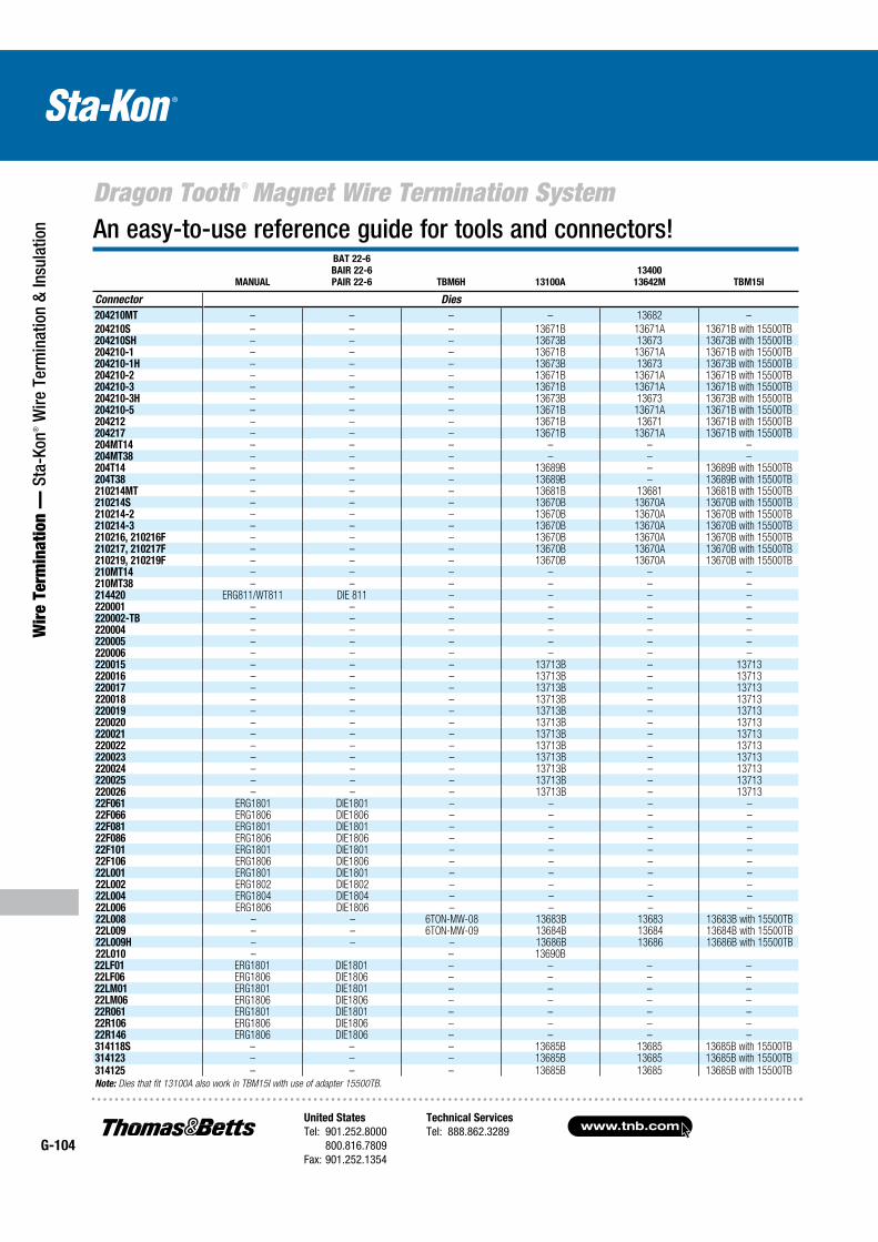
www.tnb.comUnited States
Tel: 901.252.8000 800.816.7809Fax: 901.252.1354
Technical Services
Tel: 888.862.3289G-104
Dragon Tooth ® Magnet Wire Termination System
Wir
e Te
rmin
atio
n —
Sta
-Kon
® W
ire T
erm
inat
ion
& In
sula
tion An easy-to-use reference guide for tools and connectors!
MANUAL
BAT 22-6
BAIR 22-6
PAIR 22-6 TBM6H 13100A
13400
13642M TBM15I
Connector Dies
204210MT – – – – 13682 –
204210S – – – 13671B 13671A 13671B with 15500TB204210SH – – – 13673B 13673 13673B with 15500TB204210-1 – – – 13671B 13671A 13671B with 15500TB204210-1H – – – 13673B 13673 13673B with 15500TB204210-2 – – – 13671B 13671A 13671B with 15500TB204210-3 – – – 13671B 13671A 13671B with 15500TB204210-3H – – – 13673B 13673 13673B with 15500TB204210-5 – – – 13671B 13671A 13671B with 15500TB204212 – – – 13671B 13671 13671B with 15500TB204217 – – – 13671B 13671A 13671B with 15500TB204MT14 – – – – – –204MT38 – – – – – –204T14 – – – 13689B – 13689B with 15500TB204T38 – – – 13689B – 13689B with 15500TB210214MT – – – 13681B 13681 13681B with 15500TB210214S – – – 13670B 13670A 13670B with 15500TB210214-2 – – – 13670B 13670A 13670B with 15500TB210214-3 – – – 13670B 13670A 13670B with 15500TB210216, 210216F – – – 13670B 13670A 13670B with 15500TB210217, 210217F – – – 13670B 13670A 13670B with 15500TB210219, 210219F – – – 13670B 13670A 13670B with 15500TB210MT14 – – – – – –210MT38 – – – – – –214420 ERG811/WT811 DIE 811 – – – –220001 – – – – – –220002-TB – – – – – –220004 – – – – – –220005 – – – – – –220006 – – – – – –220015 – – – 13713B – 13713220016 – – – 13713B – 13713220017 – – – 13713B – 13713220018 – – – 13713B – 13713220019 – – – 13713B – 13713220020 – – – 13713B – 13713220021 – – – 13713B – 13713220022 – – – 13713B – 13713220023 – – – 13713B – 13713220024 – – – 13713B – 13713220025 – – – 13713B – 13713220026 – – – 13713B – 1371322F061 ERG1801 DIE1801 – – – –22F066 ERG1806 DIE1806 – – – –22F081 ERG1801 DIE1801 – – – –22F086 ERG1806 DIE1806 – – – –22F101 ERG1801 DIE1801 – – – –22F106 ERG1806 DIE1806 – – – –22L001 ERG1801 DIE1801 – – – –22L002 ERG1802 DIE1802 – – – –22L004 ERG1804 DIE1804 – – – –22L006 ERG1806 DIE1806 – – – –22L008 – – 6TON-MW-08 13683B 13683 13683B with 15500TB22L009 – – 6TON-MW-09 13684B 13684 13684B with 15500TB22L009H – – – 13686B 13686 13686B with 15500TB22L010 – – 13690B22LF01 ERG1801 DIE1801 – – – –22LF06 ERG1806 DIE1806 – – – –22LM01 ERG1801 DIE1801 – – – –22LM06 ERG1806 DIE1806 – – – –22R061 ERG1801 DIE1801 – – – –22R106 ERG1806 DIE1806 – – – –22R146 ERG1806 DIE1806 – – – –314118S – – – 13685B 13685 13685B with 15500TB314123 – – – 13685B 13685 13685B with 15500TB314125 – – – 13685B 13685 13685B with 15500TBNote: Dies that fit 13100A also work in TBM15I with use of adapter 15500TB.