Embed Size (px)
Citation preview

IntroductionThe goal of this document is to provide a description of Current Control, Surge Protection and Thermal Protection managementin ST8500 device.
Current Control, Surge Protection and Thermal Protection have the purpose to protect the Line Driver against anomalousevents.• Current Control manages the current flowing into Line Driver, basing on available Power budget.• Surge Protection is active for spurious current spikes due to transient events on Power Line.• Thermal Protection is necessary to avoid an excessive temperature increase and consequent drop on transmission
performance.
If not properly managed, all 3 above events could bring to permanent damages in the Line Driver circuitry.
ST8500 Current control, surge protection and thermal control strategies
AN5581
Application note
AN5581 - Rev 1 - November 2020For further information contact your local STMicroelectronics sales office.
www.st.com
1 Document conventions
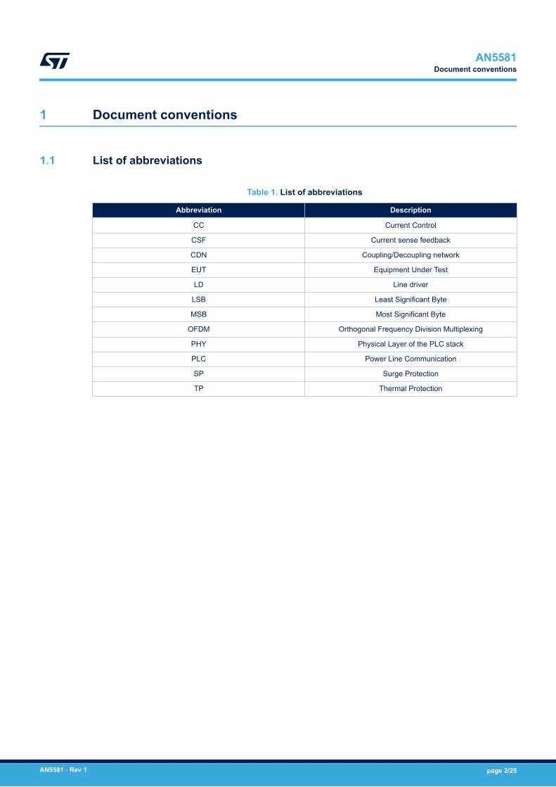
1.1 List of abbreviations
Table 1. List of abbreviations
Abbreviation Description
CC Current Control
CSF Current sense feedback
CDN Coupling/Decoupling network
EUT Equipment Under Test
LD Line driver
LSB Least Significant Byte
MSB Most Significant Byte
OFDM Orthogonal Frequency Division Multiplexing
PHY Physical Layer of the PLC stack
PLC Power Line Communication
SP Surge Protection
TP Thermal Protection
AN5581Document conventions
AN5581 - Rev 1 page 2/25

2 Block diagram
A simplified block diagram of connections between ST8500 and STLD1 is shown in Figure 1.The PA output current feedback is provided by the STLD1 on CSF_OUT pin, which is converted into voltage by aresistor and sampled by an ST8500 internal comparator connected to CSF_IN pin.The thermal feedback is provided by the STLD1 on LD_THERMAL line, based on the reference current providedon LD_BIAS by the ST8500.
Figure 1. ST8500 block diagram
AN5581Block diagram
AN5581 - Rev 1 page 3/25

3 Current control and surge protection specifications
3.1 Current control
Current Control acts in the following way: based on CS_SEL input value, the LD output current is kept below therelated threshold value.
3.1.1 Current control on G3-PLCTable 2 shows different thresholds for current control trigger on G3-PLC protocol (PE:ST8500_G3_v1390B5EC_4.4.9, RTE: STARCOM_G3_RT_FW_r1_6rc2_BA_key0).Please note that these are I(PAOUT) RMS target values.
Table 2. CFS_IN thresholds vs current limit on G3-PLC
CS_SEL value
CSF_IN Current
control comparator
threshold typ [V]
G3-PLC
Cenelec-a Cenelec-b Fcc
I (PAOUT) Rms
Value
[A]
I (PAOUT) Rms
Value
[A]
I (PAOUT) Rms
Value
[A]
0x0 0.240 0.224 0.432 0.192
0x1 0.269 0.250 0.484 0.241
0x2 0.299 0.280 0.543 0.269
0x3 0.329 0.383 0.600 0.302
0x4 0.359 0.476 0.600 0.302
0x5 0.386 0.666 0.666 0.338
0x6 0.429 0.829 0.747 0.381
0x7 0.472 0.917 0.827 0.421
0x8 0.514 1.006 1.032 0.472
0x9 0.556 0.472
0xA 0.786 0.665
0xB 0.856 0.741
0xC 0.926 0.829
0xD 0.996 0.932
0xE 1.066 0.932
0xF 1.135 1.038
If CS_SEL value is set higher than 0xF, the current control strategy is disabled.Note that CSF current ratio has a non-negligible spread; therefore, current values can vary by +/- 2dB withrespect to the nominal value.
3.1.2 Current control on PRIME 1.4Table 3 shows different thresholds for current control trigger on PRIME 1.4 protocol (PE:ST8500_PRIME_1_4_CPU_v908, RTE: ST8500_PRIME_1_4_RT_v6250). Please note that these are I(PAOUT)RMS target values.
AN5581Current control and surge protection specifications
AN5581 - Rev 1 page 4/25

Table 3. CSF_IN thresholds vs current limit on G3-PLC
CS_SEL value
CSF_IN Current
control
comparatorthreshold typ [V]
PRIME 1.4, BPSK-ROB modulation, scheme B
I (PAOUT) RMS value
[A]
CH1 CH2 CH3 CH4 CH5 CH6 CH7 CH8
0x0 0.240 0.155 0.338 0.358 0.415 0.683 0.376 0.572 0.308
0x1 0.269 0.173 0.380 0.402 0.485 0.767 0.420 0.638 0.343
0x2 0.299 0.193 0.423 0.445 0.526 0.863 0.473 0.715 0.384
0x3 0.329 0.215 0.477 0.501 0.595 0.970 0.526 0.800 0.433
0x4 0.359 0.241 0.526 0.556 0.639 1.068 0.592 0.892 0.489
0x5 0.386 0.266 0.588 0.621 0.691 0.659 0.997 0.548
0x6 0.429 0.297 0.659 0.698 0.859 0.736 1.106 0.614
0x7 0.472 0.373 0.719 0.779 0.987 0.826 0.684
0x8 0.514 0.415 0.749 0.873 1.085 0.920 0.766
0x9 0.556 0.466 0.895 0.983 1.027 0.855
0xA 0.786 0.815 0.977 1.095 1.060
0xB 0.856 0.888
0xC 0.926 1.064
0xD 0.996
0xE 1.066
0xF 1.135
If CS_SEL value is set higher than 0xF, the current control strategy is disabled.Note that CSF current ratio has a non-negligible spread; therefore, current values can vary by +/- 2dB withrespect to the nominal value.
3.2 Surge protection
The ST8500 integrates a second comparator on CSF_IN for Surge Protection. Since a surge event createsspurious current peaks with shorter duration and higher amplitude, an independent detection is needed.Surge protection is activated if LD output current rises above the CC_SURGE (CSF_IN surge comparatorthreshold) value.Table 4 shows different thresholds for surge protection trigger. Note that the spread of the CSF current ratioparameter impacts also the Surge protection algorithm.
Table 4. CC_Surge comparator thresholds
CS_SURGE_SELvalue
CC_SURGE
comparator
threshold (typ) [V]
I(PAOUT)
Inst. value [A]
0x0 0.485 1.627
0x1 0.527 1.768
0x2 0.569 1.909
0x3 0.799 2.680
0x4 0.869 2.915
AN5581Surge protection
AN5581 - Rev 1 page 5/25

CS_SURGE_SELvalue
CC_SURGE
comparator
threshold (typ) [V]
I(PAOUT)
Inst. value [A]
0x5 0.939 3.150
0x6 1.009 3.385
0x7 1.079 3.619
0x8 1.149 3.854
0x9 1.222 4.099
0xA 1.290 4.327
0xB 1.362 4.569
0xC 1.430 4.797
0xD 1.502 5.038
0xE 1.570 5.266
0xF 1.650 5.535
3.3 Current control and surge protection attributes
For the ST8500 device, management of Current control and surge protection is done by setting the attributes:phyCurrentSenseMaxThreshold & phyCurrentSenseSpikesFilter on G3-PLC.phyCurrentControlMaxThreshold & phyCurrentControlSpikesFilter on PRIME 1.4.
3.3.1 G3-PLC attributesphyCurrentSenseMaxThreshold attribute represents the maximum value of voltage/current sustained beforecurrent control activation. Its size is 16 bits and has the following characteristic:• Bits 0-7: set CS_SEL for current control• Bits 8-15: CS_SEL_SURGE for surge protection
phyCurrentSenseSpikesFilter attribute represents the minimum time interval over the current threshold value,expressed in number of 38.4 MHz AFE clock cycles, necessary to trigger the comparator output. The size of thisattribute is 32 bits, arranged as follows:• Bits 0-15: spike filter for current control• Bits 16-31: spike filter for surge protection
Default values are shown in Table 5 .
Table 5. Default attributes related to current control and surge protection on G3-PLC
AttributeG3-PLC
CEN-A CEN-B FCC
phyCurrentSenseMaxThreshold 0x0F08 0x0F08 0x0F0F
phyCurrentSenseSpikesFilter 0x000100CF 0x00010079 0x000F001F
These values have been characterized and validated by ST; however, the two attributes are exported forpossible adjustment based on field experience. ST strongly recommends, in case of need, to act only onphyCurrentSenseMaxThreshold attribute.An indication of CC activation is into G3PHY-DATA.Confirm:• CSThresholdEvents: The number of events that triggers the current control algorithm during the frame
transmission. If this value is equal to zero, no CC intervention occurred.• TxPowerBegin: The transmission power at the begin of the frame transmission.
AN5581Current control and surge protection attributes
AN5581 - Rev 1 page 6/25

• TxPowerEnd: The transmission power at the end of the frame transmission.
3.3.2 Prime 1.4 attributesphyCurrentControlMaxThreshold attribute represents the maximum value of voltage/current sustained beforecurrent control activation. Its size is 32 bits and has the following characteristic:• Bits 0-7: set CS_SEL for current control on preamble section.• Bits 8-15: set CS_SEL_SURGE for surge protection on preamble section.• Bits 16-23: set CS_SEL for current control on payload section.• Bits 24-31: set CS_SEL_SURGE for surge protection on payload section.
phyCurrentControlSpikesFilter attribute represents the minimum time interval over the current threshold value,expressed in number of 38.4 MHz AFE clock cycles, necessary to trigger the comparator output. The size of thisattribute is 32 bits, arranged as follows:• Bits 0-15: spike filter for current control.• Bits 16-31: spike filter for surge protection.
Default values are shown in Table 6 .
Table 6. Default attributes related to current control and surge protection on PRIME 1.4
Channel # phyCurrentControlMaxThreshold phyCurrentControlSpikesFilter
1 0x0F0C0F0A 0x00000060
2 0x0F0A0F09 0x00000055
3 0x0F0A0F08 0x00000040
4 0x0F080F05 0x00000035
5 0x0F040F03 0x00000030
6 0x0F090F08 0x00000022
7 0x0F060F05 0x00000021
8 0x0F0A0F09 0x00000018
These values have been characterized and validated by ST; however, the two attributes are exported for possibleadjustment based on field experience. ST strongly recommends, in case of need, to act only on bits 16-23 ofphyCurrentControlMaxThreshold attribute (as an example, for channel #1, default 0x0F0C0F0A, byte highlightedin bold).Another relevant attribute is phyCurrentControlStatus, with 16 bit size, arranged as follows:• Bits 0-7: number of Current Sense Threshold events fired during last transmissions. It corresponds to the
number of dB decrease during last transmission and is an indication of current control activation (if this valueis equal to 0x00, no CC intervention).
• Bits 15-8: transmission power configured at the beginning of transmission (maximum: level 0, minimum:level 7).
AN5581Current control and surge protection attributes
AN5581 - Rev 1 page 7/25

4 Current control and surge protection characterization
The following sections will show 3 cases: no intervention, current control activation and surge protection trigger.Characterization has been performed on G3-PLC with FW version 4.4.9.Measurement setup is shown in Figure 2 .
Figure 2. Current control and surge protection characterization setup
AN5581Current control and surge protection characterization
AN5581 - Rev 1 page 8/25

4.1 No intervention
Test #1 was done with the following conditions:• PVCC = 15 V• Short circuit between L-N• G3-PLC ROBO Differential modulation• CEN-A band• Packet size: 128 bytes• TX Power: 0x1C• phyCurrentSenseMaxThreshold (default): 0x0F08
– CS_SURGE SEL = 0x0F → Target values:◦ CSF_IN_SURGE comparator threshold = 1.650 V
◦ I(PA_OUT) Inst. value = 5.535 A– CS_SEL = 0x08 → Target values:– ◦ I(PA_OUT) RMS value = 1.006 A
• phyCurrentSenseSpikesFilter (default): 0x000100CF
Figure 3. Test #1 – results
In this case, current control wasn’t triggered & no surge events occurred.
AN5581No intervention
AN5581 - Rev 1 page 9/25

4.2 Current control activation
Test #2 was done with the following conditions:• PVCC = 15 V• Short circuit between L-N• G3-PLC ROBO Differential modulation• CEN-A band• Packet size: 128 bytes• TX Power: 0x20• phyCurrentSenseMaxThreshold (default): 0x0F08
– CS_SURGE SEL = 0x0F → Target values:◦ CSF_IN_SURGE comparator threshold = 1.650 V
◦ I(PA_OUT) Inst. value = 5.535 A– CS_SEL = 0x08 → Target values:– ◦ I(PA_OUT) RMS value = 1.006 A
• phyCurrentSenseSpikesFilter (default): 0x000100CF
Figure 4. Test #2 – before CC intervention
I(PA_OUT) RMS value = 1.157 A > 1.006 A → Current Control was correctly triggered.
AN5581Current control activation
AN5581 - Rev 1 page 10/25

Figure 5. Test #2 – after CC intervention
I(PA_OUT) RMS value = 1.003 A < 1.006A → the Current Control algorithm has effectively reduced the currentbelow the threshold value.
AN5581Current control activation
AN5581 - Rev 1 page 11/25

4.3 Surge protection activation
Test #3 was done with the following conditions:• PVCC = 15 V• Short circuit between L-N• G3-PLC ROBO Differential modulation• CEN-A band• Packet size: 128 bytes• TX Power: 0x1C• phyCurrentSenseMaxThreshold (default): 0x0608
– CS_SURGE SEL = 0x06 → Target values:◦ CSF_IN_SURGE comparator threshold = 1.009 V
◦ I(PA_OUT) Inst. value = 3.385 A– CS_SEL = 0x08 → Target values:– ◦ I(PA_OUT) RMS value = 1.006 A
• phyCurrentSenseSpikesFilter (default): 0x000100CF
Figure 6. Test #3 – results
A surge event was detected (CSF_IN voltage value = 1.04 V > 1.009 V) and the transmission was immediatelyinterrupted.
AN5581Surge protection activation
AN5581 - Rev 1 page 12/25

5 Surge protection behavior vs IEC 61000-4-5 surge immunity test
Surge immunity test was performed with the setup shown in Figure 7 .
Figure 7. Surge immunity test setup
The purpose of this test is to verify the impact on protection intervention during a PLC transmission when realsurge spike occurs on EUT. The applied stress is according to IEC 61000-4-5, level 4 (4 kV).The trial was done under two different conditions:1. Surge with EUT not transmitting2. Surge with EUT in transmission modeThe waveforms from one surge test event in condition 1 (coupling = L vs N, polarity = positive, phase shift = zero)are shown in Figure 8.
AN5581Surge protection behavior vs IEC 61000-4-5 surge immunity test
AN5581 - Rev 1 page 13/25

Figure 8. Condition 1 waveforms
Surge voltage maximum amplitude is 2 kV, due to load impedance at EUT side and to the activation of clampcircuitry of EUT.CSF first spike is evidently due to inductive effects, since the EUT is not in transmission, so it is not to beconsidered a real signal on CSF.As expected, I(PA_OUT) is null, since the EUT wasn’t transmitting.The waveforms from one surge test event in condition 2 (coupling = L vs N, polarity = positive, phase shift = zero)are depicted in Figure 9.
AN5581Surge protection behavior vs IEC 61000-4-5 surge immunity test
AN5581 - Rev 1 page 14/25

Figure 9. Condition 2 waveforms – SP intervention
On Figure 9 , the effect of surge protection is visible: the transmission is turned off immediately when CSF surgethreshold voltage is reached (1.650V as default value). Therefore, I(PA_out) becomes null.Even in condition 2, the first CSF spike can be attributed to inductive effects. The actual CSF signal correspondsto the real I(PA_OUT) current waveform reaching 5.7 A peak (excessive current with respect to the normaloperational conditions) while the CSF voltage correspondingly exceeds the surge protection threshold, activatingthe protection.Surge protection is triggered when spurious current spike occurs during one transmitted frame. The Line Driver isenabled again at the next transmission request.
AN5581Surge protection behavior vs IEC 61000-4-5 surge immunity test
AN5581 - Rev 1 page 15/25

6 Thermal protection characterization
In the ST implementation of G3-PLC, information of STLD1 thermal status is provided by the attributephyThermalStatus. Its size is 8 bits. It stores the thermal status coming from STLD1 thermometer.The bits 0-3 correspond to LD_THERMOMETER and their mapping is the following:• 0: T < 70°C;• 1: 70°C ≤ T < 100°C;• 2: 100°C ≤ T < 125°C;• 3: 125°C ≤ T < 170°C;• 4: T ≥ 170°C
Here below the measurement setup used for Thermal Protection activation.
Figure 10. Thermal protection trigger setup
Test #4 has been performed with• PVCC = 15 V• Short circuit between L-N• G3-PLC ROBO Differential modulation• FCC band• TX Power: 0x20
AN5581Thermal protection characterization
AN5581 - Rev 1 page 16/25

• Capture of first 3 thermal events
Figure 11. Thermal protection events
Packet duration is around 14 ms, as shown in Figure 13.
AN5581Thermal protection characterization
AN5581 - Rev 1 page 17/25

Figure 12. Packet duration measurement
The transmit cycle time (distance between start of one packet and next one) is around 34 ms, as shown inFigure 14.
AN5581Thermal protection characterization
AN5581 - Rev 1 page 18/25

Figure 13. Transmit cycle time measurement
Based on these results, it’s possible to find a correlation between thermal event numbers and event time.Considering in detail event #2 (yellow circle) and event #3 (green circle), the first thermal event occurred attransmitted packet #216 and the second one at packet #230: it means that there is a distance of 14 cycles.
Time interval between event #2 & event #3 is around 485 ms. This result is consistent with the distance of 14cycles (time interval between two packets is about 34 ms, so 485/34 ≈ 14).
AN5581Thermal protection characterization
AN5581 - Rev 1 page 19/25

Figure 14. Time interval measurement between thermal event #2 and #3
AN5581Thermal protection characterization
AN5581 - Rev 1 page 20/25

Revision history
Table 7. Document revision history
Date Version Changes
26-Nov-2020 1 Initial release.
AN5581
AN5581 - Rev 1 page 21/25

Contents
1 Document conventions . . . . . . . . . . . . . . . . . . . . . . . . . . . . . . . . . . . . . . . . . . . . . . . . . . . . . . . . . . . .2
1.1 List of abbreviations . . . . . . . . . . . . . . . . . . . . . . . . . . . . . . . . . . . . . . . . . . . . . . . . . . . . . . . . . . . . 2
2 Block diagram . . . . . . . . . . . . . . . . . . . . . . . . . . . . . . . . . . . . . . . . . . . . . . . . . . . . . . . . . . . . . . . . . . . . .3
3 Current control and surge protection specifications. . . . . . . . . . . . . . . . . . . . . . . . . . . . . . . .4
3.1 Current control. . . . . . . . . . . . . . . . . . . . . . . . . . . . . . . . . . . . . . . . . . . . . . . . . . . . . . . . . . . . . . . . . 4
3.1.1 Current control on G3-PLC . . . . . . . . . . . . . . . . . . . . . . . . . . . . . . . . . . . . . . . . . . . . . . . . . 4
3.1.2 Current control on PRIME 1.4 . . . . . . . . . . . . . . . . . . . . . . . . . . . . . . . . . . . . . . . . . . . . . . . 4
3.2 Surge protection . . . . . . . . . . . . . . . . . . . . . . . . . . . . . . . . . . . . . . . . . . . . . . . . . . . . . . . . . . . . . . . 5
3.3 Current control and surge protection attributes . . . . . . . . . . . . . . . . . . . . . . . . . . . . . . . . . . . . . . 6
3.3.1 G3-PLC attributes . . . . . . . . . . . . . . . . . . . . . . . . . . . . . . . . . . . . . . . . . . . . . . . . . . . . . . . . 6
3.3.2 Prime 1.4 attributes . . . . . . . . . . . . . . . . . . . . . . . . . . . . . . . . . . . . . . . . . . . . . . . . . . . . . . . 7
4 Current control and surge protection characterization. . . . . . . . . . . . . . . . . . . . . . . . . . . . . .8
4.1 No intervention . . . . . . . . . . . . . . . . . . . . . . . . . . . . . . . . . . . . . . . . . . . . . . . . . . . . . . . . . . . . . . . . 9
4.2 Current control activation . . . . . . . . . . . . . . . . . . . . . . . . . . . . . . . . . . . . . . . . . . . . . . . . . . . . . . . 10
4.3 Surge protection activation. . . . . . . . . . . . . . . . . . . . . . . . . . . . . . . . . . . . . . . . . . . . . . . . . . . . . . 12
5 Surge protection behavior vs IEC 61000-4-5 surge immunity test . . . . . . . . . . . . . . . . . .13
6 Thermal protection characterization. . . . . . . . . . . . . . . . . . . . . . . . . . . . . . . . . . . . . . . . . . . . . . .16
Revision history . . . . . . . . . . . . . . . . . . . . . . . . . . . . . . . . . . . . . . . . . . . . . . . . . . . . . . . . . . . . . . . . . . . . . . .21
Contents . . . . . . . . . . . . . . . . . . . . . . . . . . . . . . . . . . . . . . . . . . . . . . . . . . . . . . . . . . . . . . . . . . . . . . . . . . . . . .22
List of tables . . . . . . . . . . . . . . . . . . . . . . . . . . . . . . . . . . . . . . . . . . . . . . . . . . . . . . . . . . . . . . . . . . . . . . . . . .23
List of figures. . . . . . . . . . . . . . . . . . . . . . . . . . . . . . . . . . . . . . . . . . . . . . . . . . . . . . . . . . . . . . . . . . . . . . . . . .24
AN5581Contents
AN5581 - Rev 1 page 22/25

List of tablesTable 1. List of abbreviations . . . . . . . . . . . . . . . . . . . . . . . . . . . . . . . . . . . . . . . . . . . . . . . . . . . . . . . . . . . . . . . . . . 2Table 2. CFS_IN thresholds vs current limit on G3-PLC. . . . . . . . . . . . . . . . . . . . . . . . . . . . . . . . . . . . . . . . . . . . . . . . 4Table 3. CSF_IN thresholds vs current limit on G3-PLC. . . . . . . . . . . . . . . . . . . . . . . . . . . . . . . . . . . . . . . . . . . . . . . . 5Table 4. CC_Surge comparator thresholds . . . . . . . . . . . . . . . . . . . . . . . . . . . . . . . . . . . . . . . . . . . . . . . . . . . . . . . . 5Table 5. Default attributes related to current control and surge protection on G3-PLC . . . . . . . . . . . . . . . . . . . . . . . . . . . 6Table 6. Default attributes related to current control and surge protection on PRIME 1.4 . . . . . . . . . . . . . . . . . . . . . . . . . 7Table 7. Document revision history . . . . . . . . . . . . . . . . . . . . . . . . . . . . . . . . . . . . . . . . . . . . . . . . . . . . . . . . . . . . . 21
AN5581List of tables
AN5581 - Rev 1 page 23/25

List of figuresFigure 1. ST8500 block diagram. . . . . . . . . . . . . . . . . . . . . . . . . . . . . . . . . . . . . . . . . . . . . . . . . . . . . . . . . . . . . . . 3Figure 2. Current control and surge protection characterization setup . . . . . . . . . . . . . . . . . . . . . . . . . . . . . . . . . . . . . 8Figure 3. Test #1 – results . . . . . . . . . . . . . . . . . . . . . . . . . . . . . . . . . . . . . . . . . . . . . . . . . . . . . . . . . . . . . . . . . . . 9Figure 4. Test #2 – before CC intervention . . . . . . . . . . . . . . . . . . . . . . . . . . . . . . . . . . . . . . . . . . . . . . . . . . . . . . . 10Figure 5. Test #2 – after CC intervention . . . . . . . . . . . . . . . . . . . . . . . . . . . . . . . . . . . . . . . . . . . . . . . . . . . . . . . . 11Figure 6. Test #3 – results . . . . . . . . . . . . . . . . . . . . . . . . . . . . . . . . . . . . . . . . . . . . . . . . . . . . . . . . . . . . . . . . . . 12Figure 7. Surge immunity test setup . . . . . . . . . . . . . . . . . . . . . . . . . . . . . . . . . . . . . . . . . . . . . . . . . . . . . . . . . . . 13Figure 8. Condition 1 waveforms . . . . . . . . . . . . . . . . . . . . . . . . . . . . . . . . . . . . . . . . . . . . . . . . . . . . . . . . . . . . . 14Figure 9. Condition 2 waveforms – SP intervention . . . . . . . . . . . . . . . . . . . . . . . . . . . . . . . . . . . . . . . . . . . . . . . . . 15Figure 10. Thermal protection trigger setup . . . . . . . . . . . . . . . . . . . . . . . . . . . . . . . . . . . . . . . . . . . . . . . . . . . . . . . 16Figure 11. Thermal protection events . . . . . . . . . . . . . . . . . . . . . . . . . . . . . . . . . . . . . . . . . . . . . . . . . . . . . . . . . . . 17Figure 12. Packet duration measurement . . . . . . . . . . . . . . . . . . . . . . . . . . . . . . . . . . . . . . . . . . . . . . . . . . . . . . . . 18Figure 13. Transmit cycle time measurement . . . . . . . . . . . . . . . . . . . . . . . . . . . . . . . . . . . . . . . . . . . . . . . . . . . . . . 19Figure 14. Time interval measurement between thermal event #2 and #3 . . . . . . . . . . . . . . . . . . . . . . . . . . . . . . . . . . 20
AN5581List of figures
AN5581 - Rev 1 page 24/25

IMPORTANT NOTICE – PLEASE READ CAREFULLY
STMicroelectronics NV and its subsidiaries (“ST”) reserve the right to make changes, corrections, enhancements, modifications, and improvements to STproducts and/or to this document at any time without notice. Purchasers should obtain the latest relevant information on ST products before placing orders. STproducts are sold pursuant to ST’s terms and conditions of sale in place at the time of order acknowledgement.
Purchasers are solely responsible for the choice, selection, and use of ST products and ST assumes no liability for application assistance or the design ofPurchasers’ products.
No license, express or implied, to any intellectual property right is granted by ST herein.
Resale of ST products with provisions different from the information set forth herein shall void any warranty granted by ST for such product.
ST and the ST logo are trademarks of ST. For additional information about ST trademarks, please refer to www.st.com/trademarks. All other product or servicenames are the property of their respective owners.
Information in this document supersedes and replaces information previously supplied in any prior versions of this document.
© 2020 STMicroelectronics – All rights reserved
AN5581
AN5581 - Rev 1 page 25/25