Embed Size (px)
Citation preview

November 2012 Doc ID 023619 Rev 1 1/27
UM1573User manual
ST7540 power line modem firmware stack
IntroductionThis document explains how to use the firmware stack protocol designed for an STM32F103xx microcontroller interfaced with an ST7540 FSK power line transceiver.
The firmware is organized in a layer structure and is able to drive the ST7540 transceiver, implementing a communication protocol for the data transfer between two or more devices connected to the same power line. The stack is also able to manage the possible conflicts, the data acknowledgement and the repetitions in the case of data loss.
This firmware stack is developed using the STM32F103xx Standard Peripherals Library Rel.3.5.0 and IAR Embedded Workbench IDE for STM32F103xx microcontrollers Rel. 6.3.
www.st.com

Contents UM1573
2/27 Doc ID 023619 Rev 1
Contents
1 Network model description . . . . . . . . . . . . . . . . . . . . . . . . . . . . . . . . . . . 4
2 ST7540 stack firmware code . . . . . . . . . . . . . . . . . . . . . . . . . . . . . . . . . . 6
2.1 ST7540 driver layer . . . . . . . . . . . . . . . . . . . . . . . . . . . . . . . . . . . . . . . . . . 8
2.1.1 PLM initialization . . . . . . . . . . . . . . . . . . . . . . . . . . . . . . . . . . . . . . . . . . 10
2.1.2 Receiving data from power line modem . . . . . . . . . . . . . . . . . . . . . . . . . 11
2.1.3 Transmitting data to power line modem . . . . . . . . . . . . . . . . . . . . . . . . . 11
2.2 Data link and network level . . . . . . . . . . . . . . . . . . . . . . . . . . . . . . . . . . . 12
2.2.1 Stack initialization . . . . . . . . . . . . . . . . . . . . . . . . . . . . . . . . . . . . . . . . . 16
2.2.2 Stack data reception service (NL_NetworkIndication) . . . . . . . . . . . . . . 18
2.2.3 Stack data transmission service (NL_NetworkRequest) . . . . . . . . . . . . 20
2.2.4 Other stack interface APIs . . . . . . . . . . . . . . . . . . . . . . . . . . . . . . . . . . . 21
3 Stack firmware structure . . . . . . . . . . . . . . . . . . . . . . . . . . . . . . . . . . . . 23
4 References . . . . . . . . . . . . . . . . . . . . . . . . . . . . . . . . . . . . . . . . . . . . . . . . 25
5 Revision history . . . . . . . . . . . . . . . . . . . . . . . . . . . . . . . . . . . . . . . . . . . 26

UM1573 List of figures
Doc ID 023619 Rev 1 3/27
List of figures
Figure 1. CSMA/CA . . . . . . . . . . . . . . . . . . . . . . . . . . . . . . . . . . . . . . . . . . . . . . . . . . . . . . . . . . . . . . . 4Figure 2. Data exchange diagram . . . . . . . . . . . . . . . . . . . . . . . . . . . . . . . . . . . . . . . . . . . . . . . . . . . . 5Figure 3. Firmware structure of the power line modem . . . . . . . . . . . . . . . . . . . . . . . . . . . . . . . . . . . . 6Figure 4. Data communication flow with a case of repetition . . . . . . . . . . . . . . . . . . . . . . . . . . . . . . . . 7Figure 5. Firmware stack block diagram . . . . . . . . . . . . . . . . . . . . . . . . . . . . . . . . . . . . . . . . . . . . . . . 8Figure 6. ST7540 driver structure . . . . . . . . . . . . . . . . . . . . . . . . . . . . . . . . . . . . . . . . . . . . . . . . . . . . 9Figure 7. Stack working mode bitmap definition . . . . . . . . . . . . . . . . . . . . . . . . . . . . . . . . . . . . . . . . 18Figure 8. Stack firmware structure . . . . . . . . . . . . . . . . . . . . . . . . . . . . . . . . . . . . . . . . . . . . . . . . . . . 23

Network model description UM1573
4/27 Doc ID 023619 Rev 1
1 Network model description
The power line modem firmware stack is designed to manage a network structure composed of several power line modems, called nodes. These modem nodes are distributed throughout the power line. One or more modems can be used as a data concentrator and the others as slave modems. All the nodes and the concentrator share the same power line, which is used as a data communication channel (physical means).
The network is logically designed to be a master-slave structure, where the data concentrator is considered a master device and each addressed node is the slave. And, in fact, any device can initiate the communication, thereby becoming a master, while the target node, having a unique address ID, becomes the slave device.
Each node can also act as a data repeater, without any additional programming features, increasing both the reliability of the network and the statistical probability that the information from the master to the slave is delivered even under difficult network conditions.
However, the coexistence of more than one master and more repeaters introduces the need for data collision management. Since more than one device can initiate communication at any time, this may cause a network jam, lowering overall performance. This potential problem can be solved using one of two main techniques. One of these - carrier sense multiple access with collision detect (CSMA/CD) - is used when a hardware device is able to detect any collision during the data transmission. The other - carrier sense multiple access with collision avoidance (CSMA/CA) - the one used with this transceiver, is used when the hardware does not have this capability.
Figure 1. CSMA/CA
The implemented conflict avoidance mechanism uses a backoff time and the “band in use” (BU) hardware feature of the PLM to avoid transmission conflicts. Before initiating any communication, each device waits until the band is free by checking its own BU flag. As soon as the band is free, a random backoff time is calculated. Once the backoff time has elapsed, if the band is still free, the transmission is started, otherwise the loop is started again (waiting for the BU and new backoff calculation).
t
TRANSMISSIONNode B
BACKOFFNode A
Node C
Node D
BACKOFF
BACKOFF
BACKOFF
BAND IN USE
BAND IN USE
BAND IN USE
BACKOFF
BACKOFF
BACKOFF
BACKOFF
TRANSMISSION
BAND FREE
BAND IN USE
BACKOFF
BAND IN USE BAND IN USE
BACKOFF
BAND IN USE
BACKOFF
BAND FREE
TRANSMISSION
TRANSMISSION
BAND FREE
BAND FREE
AM15243v1
UM1573 Network model description
Doc ID 023619 Rev 1 5/27
The data exchange between all the nodes connected to the same power line also uses a data frame acknowledgement mechanism. In this way, the master knows if its own transmitted data packet has been correctly delivered to the target node since it receives an acknowledgment frame for each data frame sent to a target device. This acknowledgement excludes some data frames sent in broadcast by the master.
Figure 2. Data exchange diagram
The repetition feature improves the probability that the data frame is delivered to nodes that are far away or under noisy network environments. As all the other nodes are connected in the same power line, they continuously sense the network catching all data transiting on it. Depending on the device addressing and the data frame/acknowledge flow, each node is able to detect if the sensed frame must be repeated, discharged, or processed. A data identification technique (frame ID) and the forward error correction redundancy (FEC) in the data frames are implemented in order to avoid cyclic repetitions or data loss that can cause an unnecessary increase of data traffic.
M
Sx
DATA
t2t1t0
DATSLAVt0
ACK
bACK
2 t3
TA TO E x
Receive User Data
MASTER
t
t
SEND bACKFRAMEt3
SEND ACKFRAMEt2
SEND DATAFRAMEt1
PrData
rocessing
SLAVE
x
AM15244v1

ST7540 stack firmware code UM1573
6/27 Doc ID 023619 Rev 1
2 ST7540 stack firmware code
The firmware implementing the network model previously described is structured in several layers, each one performing different operations.
Figure 3. Firmware structure of the power line modem
There are three types of frame that can be sent to the power line modem. The first are data frames, which contain the user data to send. The second are programming frames, which normally contain the programming parameters of the node, like the node unique address or other user defined programming parameters, normally used when the node is set up using external software (such as a graphical user interface) or an external device. The last are service frames, which contain parameters as well as the PLM stack parameters including timing and data repetitions, or user defined service parameters. The service frames also include parameters that set the node working model which are dependent on the network model to implement (for example, with or without acknowledgement, broadcast behavior, repetition mode).
In any case, each frame type here described is treated in the same manner by the stack, and transferred to/from the user application layer from/to the power line modem. A particular frame is the ping frame which is used to ping a remote node. As well as the remote node receiving these kinds of frames, the acknowledgement is given directly by the stack engine without notification to the upper levels. The same behavior is done with the acknowledgement frames (ACK and bACK) to the data, service or programming frames, which are managed directly by the stack.
In the PLM stack level, the user information is packed and added with the necessary information such as FEC and cyclic redundancy check - CRC, and sent to the PLM. This works both ways; if the PLM catches proper data packets, these are managed by the stack.
UUSER APPLICATION LAYER
PLM STACK
NETWORK INTERFACE
DATA LINK
PHYSICAL LAYER PLM (ST7540) DRIVER
0
0
1
0
0
1
1
0
0
POWER LINE
AM15245v1

UM1573 ST7540 stack firmware code
Doc ID 023619 Rev 1 7/27
The FEC is used to correct wrong data (if any), the CRC is also checked, and if valid data are decoded, these are sent to the user application level. The PLM stack directly manages the repetitions, the necessary timing and acknowledgements.
If the target device does not acknowledge a data frame, each neighboring node, with the repetition feature enabled, that has sensed the transited data frame, forwards it, after the acknowledge timeout, as long as the band is not already taken. This repetition mechanism, managed directly by the PLM stack engine, is done once per node until either the data frame is acknowledged or each node has repeated the data frame. The repetition mechanism is also implemented for the acknowledgement frame, when not received by the master.
Figure 4. Data communication flow with a case of repetition
As each firmware layer adds its own information to the original frame, 100 bytes of user data from the application level become more than double that at the power line level. This is mainly because of the FEC redundancy added to each byte as soon as it arrives at a target node. Network traffic is therefore reduced if the power line is not overly noisy because the FEC algorithm can adjust the corrupted information.
Each frame also contains the target address, the source address, and other parameters. These may include a flag byte indicating the network model (the flag indicates if the repetition must be ignored for this frame, or if the acknowledge is awaited), a frame ID to avoid multiple repetitions of the same frame, the CRC (CRC16) bytes, the modem preamble, the header and the postamble byte.
Another implemented mechanism related to repetitions is 'hopping.' The hop level is one of the user-defined PLM parameters and is employed to assign a certain hierarchy in the repetition. If a frame must be repeated but the hop level is lower than the one stored in the stack parameter, the frame is not forwarded. Normally, the hierarchy is set depending on the distance and the ambient noise condition. The closer the repetition-enabled node is to the concentrator, the higher the hop level, and in this way, the traffic of insignificant repetitions is reduced.
Network grouping is another feature that can be implemented by the user. If implemented, the first two bytes of any frame address, which is 6 bytes long, are considered the group address. Each frame with a group address different from the assigned group is ignored. In this way it is possible that more than one network can share the same power line without interacting with each other.
M N3
N2
N1
DATAbACK
NOT SENSED ACK
AM15246v1
ST7540 stack firmware code UM1573
8/27 Doc ID 023619 Rev 1
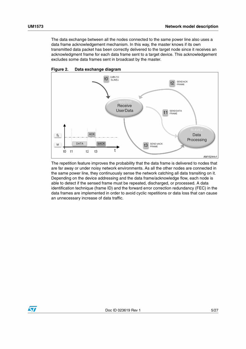
Figure 5. Firmware stack block diagram
The current firmware implementation is unique for any kind of device; master, slave, or repeater. The PLM stack is able to understand when the master, slave, or repeater state machine must be executed, depending on the data context. Figure 5 shows the block diagram of the implemented firmware stack.
2.1 ST7540 driver layerThe lower firmware layer (or level) is the physical layer which contains the ST7540 driver, and is made up of all the routines used for the transceiver configuration, initialization and management, and all the necessary STM32F103xx peripherals for configuration and setup.
For the physical ST7540 interface management (SPI and GPIOs connected to the transceiver), the STM32F103xx standard library is used. Please refer to the library user manual for more details.
In order to initialize the ST7540 hardware, the following API must be used:void PLM_PeripheralInit(PLM_IntPriorityInitTypeDef *PLM_PeripInitStruct);
In PLM_IntPriorityInitTypeDef the interrupt priorities for both the SPI peripheral and the external interrupt used for the carriage detect pin (CDPD) can be defined.
FRAMESENSED
TOUT ELAPSED(BAND FREE)
REQUEST TO SEND FRAME
PENDING ID
Node-XADDRESS
SENDACK
Node-x
REPEATACK
Node-x
Node-YADDRESS
bACKSENSED
TOUT NOTELAPSED
ACKSENSED
bACKSENSED
TOUT NOTELAPSED
TOUTELAPSED
NOTPENDING ID
CHECKFrame ID
Node-x
PENDING ID
NOT PENDING ID
ACKSENT
bACKSENT
FRAMESENT
ACKSENT
FRAMESENT
TOUT NOTELAPSED
TOUTELAPSED
ACKSENSED
bACKSENSED
Node-XADDRESS
Node-YADDRESS
bACKSENSED
NEW ID
ID ALREADYPROCESSED
BAND IN USE
BAND FREE
NOTPENDING ID
PENDING ID
CHECKpendingFrame ID
Node-x
ACKSENSED
TOUTELAPSED
REPEATbACK
Node-x Node-x CHECK
Address
STARTGlobal timeout
counter
Node-x
STOREFrame & Frame ID
Node-x
CHECKFrame ID
Node-x
IDLENode-x
STARTbACK timeout
counter
Node-x
ACK & ACK IDSTORE
ACK & ACK ID
Node-x
CHECKFrame
ADDRESS
Node-x
Node-x CHECK
Frame ID
DELIVERYERROR
Node-x
REPEATFrame
Node-x
STARTACK timeout
counter
Node-x
SENDFrame
Node-x
CHECKBAND
Node-x
SENDbACK
Node-x
AM15247v1

UM1573 ST7540 stack firmware code
Doc ID 023619 Rev 1 9/27
The data structure is the following:
typedef struct
{
/* Interrupt priorities */
uint8_t PLM_SPI_PreemptyPriority;
uint8_t PLM_SPI_SubPriority;
uint8_t PLM_CDPD_PreemptyPriority;
uint8_t PLM_CDPD_SubPriority;
}PLM_IntPriorityInitTypeDef;
Figure 6. ST7540 driver structure
Next, the ST7540 is configured and programmed by the following function:void PLM_Init(PLM_InitTypeDef *PLM_InitStruct);
This routine sets up all the modem parameters and initializes its internal registers. The structure passed to the API is the following:
typedef struct
{
PLMFreq_TypeDef PLM_BandpassFrequency;
PLMBaudrate_TypeDef PLM_BaudRate;
uint16_t PLM_HeaderPreamble;
PLMDeviation_TypeDef PLM_Deviation;
PLMPrefilter_TypeDef PLM_PreFilter;
PLMSensitivity_TypeDef PLM_Sensitivity;
}PLM_InitTypeDef;
In the stm32f10x_plm.h file all the typedefs of the previous structure with the admitted values for the PLM parameters are defined.
The following APIs are used for the ST7540 peripheral management, and are the starting point for implementing its own stack firmware.
PLM (ST7540) DRIVER SPI Std. Peripheral Lib.
EXTI Std. Peripheral Lib.
ST7540 APIs
GPIO Std. Peripheral Lib.
AM15248v1

ST7540 stack firmware code UM1573
10/27 Doc ID 023619 Rev 1
The first group returns some flags indicating if the band is in use by another device, if the current data frame has been sent or a data frame is received and if the received frame is a valid frame.
uint8_t PLM_BandInUse(void);
uint8_t PLM_FrameSent(void);
uint8_t PLM_FrameArrived(void);
uint8_t PLM_ValidFrameArrived(void);
The next group of APIs is used to send and receive a data frame.void PLM_SendData(uint8_t *buffer, uint8_t len);
void PLM_StartReceiveData(void);
uint8_t PLM_GetBufferLength(void);
uint8_t* PLM_GetReceivedBufferPointer(void);
There are also some APIs used for low level statistics, returning the number of FEC corrections done in the arrived frame and the wrong postamble indication.uint8_t PLM_GetFECCorrections(void);
PLM_WP_TypeDef PLM_GetWrongPostamble(void);
The last group of driver APIs are used for the PLM reset and internal register write/read operations.void PLM_Reset(void);
void PLM_WriteRegisters(uint8_t *buffer, uint8_t len);
void PLM_StartReadRegisters(void);?
2.1.1 PLM initialization
In this section, the instructions sequence on how to configure and use the ST7540 driver is shown.
First, the PLM must be initialized and configured by filling the init structures:
PLM_IntPriorityInitTypeDef PLM_InterruptInitStructure;
PLM_InitTypeDef PLM_InitStructure;
Configuring the PLM device and setting the correct interrupt priorities defined in the macros PLM_SPI_INT_PREEMPTY_PRIORITY and PLM_SPI_INT_SUB_PRIORITY for the SPI and PLM_CDPD_PREEMPTY_PRIORITY and PLM_CDPD_SUB_PRIORITY for the CDPD external interrupt pin, is done with the instructions:
PLM_InterruptInitStructure.PLM_SPI_PreemptyPriority = PLM_SPI_INT_PREEMPTY_PRIORITY;
PLM_InterruptInitStructure.PLM_SPI_SubPriority = PLM_SPI_INT_SUB_PRIORITY;
PLM_InterruptInitStructure.PLM_CDPD_PreemptyPriority = PLM_CDPD_PREEMPTY_PRIORITY;
PLM_InterruptInitStructure.PLM_CDPD_SubPriority = PLM_CDPD_SUB_PRIORITY;
PLM_PeripheralInit(&PLM_InterruptInitStructure);
The PLM parameters configuration, assigning the wanted values, is done with the code shown here below. In this example, PLM is configured with a bandpass filter of 132.5 KHz, a data baud rate of 2400 bps, deviation of 0.5 and high sensitivity with the prefilter on. Please refer to the ST7540 datasheets for more details on PLM parameters.

UM1573 ST7540 stack firmware code
Doc ID 023619 Rev 1 11/27
PLM_InitStructure.PLM_HeaderPreamble = HEADER_PREAMBLE_VALUE;
PLM_InitStructure.PLM_BandpassFrequency = PLM_PB_FREQ_132KHz;
PLM_InitStructure.PLM_BaudRate = PLM_BAUDRATE_2400;
PLM_InitStructure.PLM_Deviation = PLM_DEVIATION_05;
PLM_InitStructure.PLM_PreFilter = PLM_PRE_FILTER_ON;
PLM_InitStructure.PLM_Sensitivity = PLM_SENSITIVITY_HIGH;
In order to load the parameters, initialize the PLM variables, reset and put the device in IDLE mode, the following APIs must be used:PLM_Init(&PLM_InitStructure);
PLM_Reset();
2.1.2 Receiving data from power line modem
The following API enables the PLM to receive data from the power line. As soon as a data frame is received, before receiving the next data frame, the function must be called again:void PLM_StartReceiveData(void);
The next instruction notifies when a data frame has arrived and is ready to be read.
if (PLM_FrameArrived())
{
...
}
Another instruction can be used instead to test if a data frame is ready in the PLM buffer, and if this is the case, it automatically removes the header and the redundancy (FEC), and checks if the data frame has a correct postamble. The data reception is automatically enabled by this API if the frame is rejected.if (PLM_ValidFrameArrived())
{
...
}
If valid data has arrived, the data length and the received data buffer are recovered by the following APIs:/* Recover received data frame length */
uint8_t plm_len = PLM_GetBufferLength();
/* Points to PLM data buffer */
uint8_t *plm_buffer = PLM_GetReceivedBufferPointer();
2.1.3 Transmitting data to power line modem
Before transmitting data, the user should check if the band is already in use (this can happen if another device is transmitting data and the PLM detects a header sequence).
if (!PLM_BandInUse())
{
...
}

ST7540 stack firmware code UM1573
12/27 Doc ID 023619 Rev 1
The buffer is then filled with the data to send and the correct buffer length is set:
/* Max payload size is 100 bytes. Do not exceeds this value */
uint8_t buffer[PAYLOAD_SIZE + LL_HDR_SIZE];
uint8_t len;
LL_HDR_SIZE is the size of some extra bytes added by the upper levels when a stack is used. Send the user bytes and wait until the transmission is completed using the following code (in this firmware release, the value of LL_HDR_SIZE is 19 bytes).
/* Send data throughout PL */
void PLM_SendData(uint8_t *buffer, uint8_t len);
/* Wait frame transmission. Manage timeout eventually or use this API in a state machine */
while (!PLM_FrameSent());
...
Some other APIs can be used for statistics, or for testing the PL performance or any other use, and for the ST7540 internal register direct access.
/* Get the number of FEC correction for the arrived frame */
uint8_t PLM_GetFECCorrections(void);
/* Get the postamble status for the arrived frame */
PLM_WP_TypeDef PLM_GetWrongPostamble(void);
/* Write a buffer of len bytes in the ST7540 internal registers /*
void PLM_WriteRegisters(u8 *buffer, u8 len);
/* Enable the ST7540 internal registers reading (use the PLM_FrameArrived() function to test the data arrived flag) */
void PLM_StartReadRegisters(void);
2.2 Data link and network levelThe data link layer implements the core of the stack protocol described at the beginning of this section. The stack is designed to work in a state machine firmware flow; this means that in a while(1) loop or in a task routine called by a timer or any other synchronous periodic event of the user application level, the stack engine update function must be called in order to update all the events and perform the consequent actions.
The interface between the user application layer and the stack link layer is the network layer. All the interface API definitions are in the stk_n.h file.

UM1573 ST7540 stack firmware code
Doc ID 023619 Rev 1 13/27
The stack engine update is done by using the NL_DeviceStackUpdate function in a non-blocking firmware flow:
void main(void)
{
/* Application initialization */
...
/* Infinitive loop */
while(1)
{
/* User application state machine */
USER_ApplicationSMupdate();
...
/* Stack engine update */
NL_DeviceStackUpdate();
}
}
or, using an asynchronous (from the program flow) interrupt event of a timer or another peripheral or external device (RTC for example):
void main(void)
{
/* Application initialization */
...
/* User application code */
...
}
/* Internal timer, task event, periodic external event... */
void Timer_InterruptRequest(void)
{
...
/* Stack engine update */
NL_DeviceStackUpdate();
}
In the interfaceconfig.h file all the macros that represent the default configuration for the chosen working model and the stack parameters are defined. All the parameters and the configuration can be set in run mode using the appropriate APIs described hereinafter.
The stack working mode configuration parameters defined in the interfaceconfig.h file are shown below. In order to disable the corresponding option, it is necessary to comment (//) the equivalent macro.

ST7540 stack firmware code UM1573
14/27 Doc ID 023619 Rev 1
/*---------------------------------------------------------------*/
/* WORKING MODE DEFINITION */
/*---------------------------------------------------------------*/
/* Comment the definition to disable the equivalent option */
/* Use the internal RTC */
#define DEVICE_USE_RTC
/* Use the external 32KHz oscillator for RTC functions */
#define DEVICE_USE_EXTOSC_32KHZ
/* Enable the internal watchdog for auto-reset */
#define DEVICE_USE_WATCHDOG
/* Enable the internal oscillator calibration (if external oscillator is not used) */
//#define DEVICE_LSI_TIM_MEASURE
/* Enable the ACK frames transmission (link stack level) */
#define DEVICE_WM_REQ_ACK
/* Enable the back ACK frames transmission (link stack level) */
#define DEVICE_WM_REQ_bACK
/* Enable the repeater mode */
#define DEVICE_WM_REPEATER
/* Enable to repeat all frames after the ACK timeout (static repeater behaviour, previous option must be enabled too) */
//#define DEVICE_WM_REPEAT_ALL
/* Enable the AES128 data encryption */
#define DEVICE_WM_ENCRYPT_DATA
/* Enable the grouping filter for subnets */
//#define DEVICE_WM_GROUP_FILTER
/* Hoping (commented, 0 or 1 = disabled, higher value = higher level. Minimum allowed value = 2) */
//#define DEVICE_HOP_LEVEL
The following parameters set up the configuration mode of the transceiver. It's important to set the PLM communication frequency at the same value of the middle frequency of the bandpass filter used in the hardware.
/* PLM communication frequency */
//#define PLM_FREQ_60KHZ // PLM comm. frequency set to 60 KHz
//#define PLM_FREQ_66KHZ // PLM comm.frequency set to 66 KHz
//#define PLM_FREQ_72KHZ // PLM comm.frequency set to 72 KHz
//#define PLM_FREQ_76KHZ // PLM comm.frequency set to 76 KHz
//#define PLM_FREQ_82KHZ // PLM comm.frequency set to 82.05 KHz
//#define PLM_FREQ_86KHZ // PLM comm.frequency set to 86 KHz
//#define PLM_FREQ_110KHZ// PLM comm.frequency set to 110 KHz
#define PLM_FREQ_132KHZ // PLM comm.frequency set to 132.6 KHz
/* PLM interface communication baudrate */

UM1573 ST7540 stack firmware code
Doc ID 023619 Rev 1 15/27
//#define PLM_600_BPS // PLM communication baudrate 600 bps
//#define PLM_1200_BPS // PLM communication baudrate 1200 bps
#define PLM_2400_BPS // PLM communication baudrate 2400 bps
//#define PLM_4800_BPS // PLM communication baudrate 4800 bps
/* PLM Sensitivity */
#define PLM_SENS_HIGH // High sensitivity
//#define PLM_SENS_NORMAL // Normal sensitivity
The stack parameters defined in the interfaceconfig.h file are explained here below.
/*---------------------------------------------------------------*/
/* DEFAULT LINK LAYER STACK DATA VALUES - <!> MODIFY WITH CARE */
/*---------------------------------------------------------------*/
/* Minimum time slot for the back off time */
#define DEFAULT_MIN_SLOT 3 // 300 us
/* Maximum time slot for the back off time */
#define DEFAULT_MAX_SLOT 500 // 50 ms
/* Timeout for complete the communication (20sec - 10sec step) */
#define DEFAULT_NTW_P_GLOBAL_TX_TO 2 // 20s
/* Timeout for broadcast frame retransmission (10sec step) */
#define DEFAULT_NTW_P_BC_GLOBAL_TX_TO 2 // 20s
/* Timeout for network inactivity (must be > NTW_P_ACK_RX_TO) */
#define DEFAULT_NTW_P_ACTIVITY_TO 20000 // 2s
/* Communication watchdog timeout */
#define DEFAULT_NTW_P_WATCHDOG_TO 6 // 1min
/* Timeout for completing a datatransfer (one way) */
#define DEFAULT_NTW_P_DATATRANSFER_TO 10 // 10s
/* Timeout for band in use (0 = no timeout check) */
#define DEFAULT_NTW_P_BANDINUSE_TO 0 // (100us step)
/* Timeout for sending a frame through SPI */
#define DEFAULT_NTW_P_FRAME_TX_TO 12000 // 1.2s
/* Timeout for repeat a broadcast frame */
#define DEFAULT_NTW_P_BCAST_TX_TO 150000 // 15s
/* Timeout for receiving an ACK {@2400bps PLM speed (worst case)} */
#define DEFAULT_NTW_P_ACK_RX_TO 2500 // 250ms
/* Timeout for receiving a bACK {@2400bps PLM speed (worst case)} */
#define DEFAULT_NTW_P_bACK_RX_TO 2500 // 250ms:
/* Timeout for frame receptions (receiver) */
#define DEFAULT_NTW_P_FRM_RX_TO 0 // (100us step)
/* Minimum delay before any transmission */
#define DEFAULT_NTW_P_NDX_TO 100 // 10ms
/* Max attempts if no activity is detected */
#define DEFAULT_LL_MAX_ATTEMPT 5
/* Max repetition attempts (for processed ID, 0 = disabled) */

ST7540 stack firmware code UM1573
16/27 Doc ID 023619 Rev 1
#define DEFAULT_MAX_RPT_ATTEMPT 0
2.2.1 Stack initialization
The following are the steps needed to configure the stack in the user application. First, all the parameters defined in the interfaceconfig.h file must be loaded in the stack configuration structures using the LL_WM_t and LL_settings_t data structure (defined in the file stk_l.h). For this issue, two initialization functions can be defined in the user application file.
LL_settings_t APP_InitStackDefaults(void)
{
LL_settings_t ds; // Typedef defined in the stk_l.h file
// Link Layer stack default settings
ds.MIN_SLOT = DEFAULT_MIN_SLOT;
ds.MAX_SLOT = DEFAULT_MAX_SLOT;
ds.GLOBAL_TX_TO = DEFAULT_NTW_P_GLOBAL_TX_TO;
ds.BC_GLOBAL_TX_TO = DEFAULT_NTW_P_BC_GLOBAL_TX_TO;
ds.ACTIVITY_TO = DEFAULT_NTW_P_ACTIVITY_TO;
ds.WATCHDOG_TO = DEFAULT_NTW_P_WATCHDOG_TO;
ds.DATATRANSFER_TO = DEFAULT_NTW_P_DATATRANSFER_TO;
ds.BANDINUSE_TO = DEFAULT_NTW_P_BANDINUSE_TO;
ds.FRAME_TX_TO = DEFAULT_NTW_P_FRAME_TX_TO;
ds.BCAST_TX_TO = DEFAULT_NTW_P_BCAST_TX_TO;
ds.ACK_RX_TO = DEFAULT_NTW_P_ACK_RX_TO;
ds.bACK_RX_TO = DEFAULT_NTW_P_bACK_RX_TO;
ds.FRM_RX_TO = DEFAULT_NTW_P_FRM_RX_TO;
ds.NDX_TO = DEFAULT_NTW_P_NDX_TO;
ds.MAX_ATTEMPT = DEFAULT_LL_MAX_ATTEMPT;
ds.MAX_RPT_ATTEMPT = DEFAULT_MAX_RPT_ATTEMPT;
ds.TIME_SYNC = DEFAULT_DEVICE_TIME_SYNC;
return ds;
}
LL_WM_t APP_InitStackWorkingMode(void)
{
LL_WM_t wm;// Typedef defined in the stk_l.h file
wm.DEVICE_OPT_ACK = LL_FRM_PARAM_DISABLED;
wm.DEVICE_OPT_bACK = LL_FRM_PARAM_DISABLED;
wm.DEVICE_OPT_RPT = LL_FRM_PARAM_DISABLED;
wm.DEVICE_OPT_RPTALL = LL_FRM_PARAM_DISABLED;
wm.DEVICE_OPT_GRP = LL_FRM_PARAM_DISABLED;
wm.DEVICE_OPT_ENC = LL_FRM_PARAM_DISABLED;
/* ACK frames */

UM1573 ST7540 stack firmware code
Doc ID 023619 Rev 1 17/27
#ifdef DEVICE_WM_REQ_ACK
wm.DEVICE_OPT_ACK = LL_FRM_PARAM_ACK_REQ;
#endif
/* bACK frames */
#ifdef DEVICE_WM_REQ_bACK
wm.DEVICE_OPT_bACK = LL_FRM_PARAM_bACK_REQ;
#endif
/* Repetitions */
#ifdef DEVICE_WM_REPEATER
wm.DEVICE_OPT_RPT = LL_FRM_PARAM_REPEAT;
#endif
#ifdef DEVICE_WM_REPEAT_ALL
wm.DEVICE_OPT_RPTALL = LL_FRM_PARAM_REPEAT_ALL;
#endif
/* Grouping */
#ifdef DEVICE_WM_GROUP_FILTER
wm.DEVICE_OPT_GRP = LL_FRM_PARAM_GROUP;
#endif
/* Encryption */
#ifdef DEVICE_WM_ENCRYPT_DATA
wm.DEVICE_OPT_ENC = LL_FRM_PARAM_ENCRYPTION;
#endif
return wm;
}
Once the initialization structures are loaded, the stack is configured with the following code:
if (NL_NetworkInit(APP_InitStackWorkingMode(), APP_InitStackDefaults()))
{
uint16_t LocalGroup;
uint32_t LocalAddress;
/* Set the current group and address */
NL_SetLocalAddress(LocalGroup, LocalAddress);
}
The NL_SetLocalAddress API sets the grouping and the address for the device. If the grouping is not used, the address is made up of both parameters, allowing a 6-byte addressing (2 for group and 4 for address).
At runtime (normally at the power-on if, for example, some or all the parameters are stored in the internal Flash memory of the STM32F103xx), it is possible to override some of the parameters set up with the previous function, using the following APIs:
/* Set the local working mode */
void NL_SetLocalWorkingMode(uint8_t WorkingMode);
where the meaning of each bit of the WorkingMode byte is explained in Figure 7.

ST7540 stack firmware code UM1573
18/27 Doc ID 023619 Rev 1
Figure 7. Stack working mode bitmap definition
/* Set the local hop level */
void NL_SetLocalHopLevel(uint8_t HopLevel);
/* Set the stack parameters (typedef defined in stk_n.h file) */
void NL_SetDataLinkStackParameters(NL_DLSP_t devparam);
2.2.2 Stack data reception service (NL_NetworkIndication)
The service used for receiving data from the network is defined in the stk_n.h file, which is the interface between the ST7540 stack and the user application level.NL_Status_t nNStatus = NL_NetworkIndication(NL_Data_t *ntw_data, uint32_t timeout);
The value returned in the nNStatus variable can be one of the values defined in the NL_Status_t structure, defined in the file stk_n.h.
if (nNStatus.operation == N_DOING)
{
/* PL: IDLE MODE */
/* User application while no data is arrived from PLM */
...
}
else if (nNStatus.operation == N_ERROR)
{
/* PL: DATA RECEPTION ERROR */
/* Error Management */
...
}
else if (nNStatus.operation == N_SUCCESS)
{
/* PL: DATA ARRIVED */
1 = Frame sent in broadcast 0 = unicast 1 = ACK frame requested 0 = ACK frame not requested 1 = b 0 = bACK frame not requested 1 = Repetition enabled 0 = Repetition disabled 1 = Repeat all 0 = Repeat after ACK timeout 1 = Grouping filter enabled 0 = Grouping filter disabled 1 = Encrypted data 0 = Clear data 0 - Reserved
WorkingMode
b7 b6 b5 b4 b3 b2 b1 b0
ACK frame requested
AM15249v1

UM1573 ST7540 stack firmware code
Doc ID 023619 Rev 1 19/27
/* Valid data arrived from PLM and addressed to this device or
sent in broadcast by a remote PLM. (broadcast frame are sent with
LL_BROADCAST_FLAG set in the ntw_data.frametype field) */
}
When valid data arrive from the power line, data can be recovered from the structure NL_Data_t (in this example, pointed by *ntw_data pointer).
typedef struct
{
uint16_t group;// Sender group
uint32_t address;// Sender address
uint8_t framelen;// Arrived frame length
NL_Type_t frametype;// Arrived frame type
uint8_t databuffer[PAYLOAD_SIZE]; // Arrived user data
}NL_Data_t;
The group field is the same as this device if the grouping option is enabled, because, by enabling the group filter, all the frames coming from a different group are ignored (even those sent in broadcast).
When the variable nNStatus.operation value is N_SUCCESS, the data are valid, meaning with a correct preamble, a correct CRC (CRC16 is automatically inserted by the stack during the transmission and checked, and then removed during the reception), with one of the admitted frame types, addressed to this device (or sent in broadcast) belonging to this group and correctly acknowledged by the sender. All of this is transparent to the user as it is automatically managed by the stack.
The fields data buffer and framelen contain the user raw data and the data length. Refer to the stk_n.h file for the admitted frame types.
If a data reception error occurs, this can be verified checking the value of the field error of the NL_Status_t structure (nNStatus.error).
The following enumerations are the possible communication errors (including also the transmission errors) and are reported in the stk_n.h file.
typedef enum
{
NL_ERR_NONE,// No error
NL_ERR_NOT_READY,// Stack not initialized
NL_ERR_NETWORK_TIMEOUT,// Given timeout elapsed
NL_ERR_TRANSMISSION_ERROR,// Data transmission error
NL_ERR_COMMUNICATION_TIMEOUT,// Communication timeout
NL_ERR_LINE_ERROR,// Power line error
NL_ERR_TARGET_NOT_REACHABLE,// Target device unreachable
NL_ERR_FRAME_CLASS_UNKNOWN,// Unknown frame type
NL_ERR_GENERIC// Unclassified error

ST7540 stack firmware code UM1573
20/27 Doc ID 023619 Rev 1
}NL_ERR_t;
2.2.3 Stack data transmission service (NL_NetworkRequest)
The service used for transmitting data from the network is also defined in the stk_n.h file:NL_Status_t nNStatus = NL_NetworkRequest(NL_Data_t *ntw_data, uint32_t timeout);
In order to transmit user data, first the NL_Data_t structure must be filled.
NL_Data_t user_data;
uint8_t i;
user_data.group = TargetDeviceGroup; // Or use as address
user_data.address = TargetDeviceAddress;
user_data.framelen = PAYLOAD_SIZE;
user_data.frametype = NL_CLS_DATA_FRAME; // Data frame is selected
/* Load user data to transmit */
for (i = 0; i < PAYLOAD_SIZE; i++)
user_data.databuffer[i] = UserData[i];
If the frame must be sent in broadcast, the fields user_data.group and user_data.address can be set to 0 (they are ignored by the other devices) and the broadcast flag must be added to the frame type:
user_data.frametype |= LL_BROADCAST_FLAG; // Send data in broadcast
The returned values are the same as for the data reception service, where the N_SUCCESS value indicates the correct data transfer with the assurance of data packet delivery. The resulting cases are the same as those of the indication service.
if (nNStatus.operation == N_DOING)
{
/* PL: IDLE MODE */
/* User application while data is being transmitting via PLM */
...
}
else if (nNStatus.operation == N_ERROR)
{
/* PL: DATA TRANSMISSION ERROR */
/* Error Management */
...
}
else if (nNStatus.operation == N_SUCCESS)
{
/* PL: DATA TRANSMITTED */

UM1573 ST7540 stack firmware code
Doc ID 023619 Rev 1 21/27
/* Data delivery to the target device successfull */
...
}
2.2.4 Other stack interface APIs
In the network interface file (stk_n.h) there are some other APIs that can be used in the user application.
The first of which is a function used to reset the state machines and restart the engines:void NL_NetworkRestart(void);
In order to know or to set the current stack settings and working mode, the following APIs are available:
/* Working mode (DNL_DLSP_t defined in stk_n.h file) */
void NL_GetDataLinkStackParameters(NL_DLSP_t *llsp);
void NL_SetDataLinkStackParameters(NL_DLSP_t llsp);
/* Get API's */
uint8_t NL_GetLocalWorkingMode(void);
uint8_t NL_GetLocalHopLevel(void);
void NL_GetLocalAddress(uint16_t *nDevGrp, uint32_t *nDevAdd);
/* Set API's */
void NL_SetLocalAddress(uint16_t nDevGrp, uint32_t nDevAdd);
void NL_SetLocalWorkingMode(uint8_t wmode);
void NL_SetLocalHopLevel(uint8_t hlevel);
To set up the working mode, it is possible to set the single flag, without changing the value of the other flags.void NL_SetLocalWorkingModeFlag(NL_WMFlag_t flag, NL_WMFlag_status_t sts);
The following is a list of the flags and the values those flags can assume.
typedef enum
{
F_BROADCAST = 0x01,
F_ACK = 0x02,
F_bACK = 0x04,
F_REPEATER = 0x08,
F_GROUP = 0x10
}NL_WMFlag_t;
typedef enum

ST7540 stack firmware code UM1573
22/27 Doc ID 023619 Rev 1
{
F_ENABLED,
F_DISABLED
}NL_WMFlag_status_t;
If the AES128 encryption is enabled, the function to use to set up the AES key is:
void NL_SetEncryptionKey(uint8_T *Ekey);
Once the encryption is enabled by selecting the DEVICE_WM_ENCRYPT_DATA option in the interfaceconfig.h file, data is encrypted using the AES128 algorithm with the supplied AES key (Ekey), and if the target device has the encryption enabled too and also has the same key, the data is correctly decoded directly by the stack. If the encryption is not enabled or the key is different, the data frame is discharged and consequently not acknowledged.
Finally, it is possible to know the stack firmware release (two bytes, in the x.y decimal format) calling the API:
/* Stack firmware release (x).(y) */
uint16_t NL_GetStackFirmwareRelease(void);

UM1573 Stack firmware structure
Doc ID 023619 Rev 1 23/27
3 Stack firmware structure
The stack firmware structure contained inside the zip file supplied with this user manual is shown in Figure 8.
Inside the root there is the interfaceconfig.h file which contains all the macros used for the stack configuration and option setup.
The src directory contains all the source files and the object files (the object files refer to the AES128.o, stk_l.o and stk_n.o files). The stk_p.c and the ST7540 driver contain the source code allowing the user to make modifications eventually required by the chosen microcontroller.
Figure 8. Stack firmware structure
The inc directory contains all the definition files to include in the user project.
Table 1 shows the stack firmware weight in terms of memory (both Flash and RAM).
The stack firmware uses some microcontroller peripheral libraries which must be considered to calculate the final code size. The used STM32F103xx microcontroller libraries are listed below:
● stm32f10x_gpio
● stm32f10x_exti
● stm32f10x_spi
● stm32f10x_rtc
● stm32f10x_bkp
● stm32f10x_iwdg
● stm32f10x_rcc
● stm32f10x_tim
● <time.h>
PLMstack45interfaceconfig.hinc
AES128.hstk_l.hstk_n.hstk_p.hstm32f10x_plm.h
srcAES128.ostk_l.ostk_n.ostk_p.cstm32f10x_plm.cstm32f10x_plm.c
stm32f10x_plm.h
h
h
h
h
h
c
c
h
ST7540 Driver
AM15250v1

Stack firmware structure UM1573
24/27 Doc ID 023619 Rev 1
where:
● ro code = bytes of read only code memory
● ro data = bytes of read only data memory
● rw data = bytes of read/write data memory.
Table 1. Stack firmware module data size
IAR ELF Linker V6.30.1.53127/W32 for ARM Copyright 2007-2011 IAR systems AB
Module ro code ro data rw data
AES128.o 2 402 2 060 152
stk_l.o 6 796 515 629
stk_n.o 1 106
stk_p.o 1 144 18
stm32f10x_plm.o 2 364 322 712
Total bytes 13 812 2 897 1 511

UM1573 References
Doc ID 023619 Rev 1 25/27
4 References
1. ARM-based 32-bit MCU STM32F10x Standard Peripheral Library Rel 3.5.0 (2011).
2. ST7540 FSK power line transceiver datasheets (2006).
3. AN3046 application note.
4. IAR embedded workbench IDE Rel. 6.3 documentation (www.iar.com).

Revision history UM1573
26/27 Doc ID 023619 Rev 1
5 Revision history
Table 2. Document revision history
Date Revision Changes
12-Nov-2012 1 Initial release.

UM1573
Doc ID 023619 Rev 1 27/27
Please Read Carefully:
Information in this document is provided solely in connection with ST products. STMicroelectronics NV and its subsidiaries (“ST”) reserve theright to make changes, corrections, modifications or improvements, to this document, and the products and services described herein at anytime, without notice.
All ST products are sold pursuant to ST’s terms and conditions of sale.
Purchasers are solely responsible for the choice, selection and use of the ST products and services described herein, and ST assumes noliability whatsoever relating to the choice, selection or use of the ST products and services described herein.
No license, express or implied, by estoppel or otherwise, to any intellectual property rights is granted under this document. If any part of thisdocument refers to any third party products or services it shall not be deemed a license grant by ST for the use of such third party productsor services, or any intellectual property contained therein or considered as a warranty covering the use in any manner whatsoever of suchthird party products or services or any intellectual property contained therein.
UNLESS OTHERWISE SET FORTH IN ST’S TERMS AND CONDITIONS OF SALE ST DISCLAIMS ANY EXPRESS OR IMPLIEDWARRANTY WITH RESPECT TO THE USE AND/OR SALE OF ST PRODUCTS INCLUDING WITHOUT LIMITATION IMPLIEDWARRANTIES OF MERCHANTABILITY, FITNESS FOR A PARTICULAR PURPOSE (AND THEIR EQUIVALENTS UNDER THE LAWSOF ANY JURISDICTION), OR INFRINGEMENT OF ANY PATENT, COPYRIGHT OR OTHER INTELLECTUAL PROPERTY RIGHT.
UNLESS EXPRESSLY APPROVED IN WRITING BY TWO AUTHORIZED ST REPRESENTATIVES, ST PRODUCTS ARE NOTRECOMMENDED, AUTHORIZED OR WARRANTED FOR USE IN MILITARY, AIR CRAFT, SPACE, LIFE SAVING, OR LIFE SUSTAININGAPPLICATIONS, NOR IN PRODUCTS OR SYSTEMS WHERE FAILURE OR MALFUNCTION MAY RESULT IN PERSONAL INJURY,DEATH, OR SEVERE PROPERTY OR ENVIRONMENTAL DAMAGE. ST PRODUCTS WHICH ARE NOT SPECIFIED AS "AUTOMOTIVEGRADE" MAY ONLY BE USED IN AUTOMOTIVE APPLICATIONS AT USER’S OWN RISK.
Resale of ST products with provisions different from the statements and/or technical features set forth in this document shall immediately voidany warranty granted by ST for the ST product or service described herein and shall not create or extend in any manner whatsoever, anyliability of ST.
ST and the ST logo are trademarks or registered trademarks of ST in various countries.
Information in this document supersedes and replaces all information previously supplied.
The ST logo is a registered trademark of STMicroelectronics. All other names are the property of their respective owners.
© 2012 STMicroelectronics - All rights reserved
STMicroelectronics group of companies
Australia - Belgium - Brazil - Canada - China - Czech Republic - Finland - France - Germany - Hong Kong - India - Israel - Italy - Japan - Malaysia - Malta - Morocco - Philippines - Singapore - Spain - Sweden - Switzerland - United Kingdom - United States of America
www.st.com


![Software Modem Discovery Evaluation Kit: User Guide · Reset 0x02 Reset modem FactoryReset 0x03 Perform modem factory reset Firmware 0x04 Write firmware update part[4+128] GetTime](https://img.pdfslide.us/doc/110x75/5e0b037d9e66b5629f4fa131/software-modem-discovery-evaluation-kit-user-guide-reset-0x02-reset-modem-factoryreset.jpg)