Embed Size (px)
Citation preview

8/3/2019 ST60 Wind Instrument Owner's Handbook
http://slidepdf.com/reader/full/st60-wind-instrument-owners-handbook 1/52
ST60 Wind &Close HauledWindInstrumentOwner’sHandbookDocument number: 81105-4
Date: 1 April 2004

8/3/2019 ST60 Wind Instrument Owner's Handbook
http://slidepdf.com/reader/full/st60-wind-instrument-owners-handbook 2/52
Raymarine, ST60 and SeaTalk are trademarks of Raymarine Limited
© Handbook contents copyright Raymarine Limited 2004

8/3/2019 ST60 Wind Instrument Owner's Handbook
http://slidepdf.com/reader/full/st60-wind-instrument-owners-handbook 3/52
Preface i
Preface
Important informationSafety notices
WARNING: Product installation & operationThis equipment must be installed and operated in accordancewith the Raymarine instructions provided. Failure to do so couldresult in personal injury, damage to your boat and/or poor productperformance.
WARNING: Electrical safetyMake sure you have switched off the power supply before youstart installing this product.
WARNING:Although we have designed this product to be accurate andreliable, many factors can affect its performance. Therefore, itshould serve only as an aid to navigation and should never replacecommonsense and navigational judgement. Always maintain a
permanent watch so you can respond to situations as theydevelop.
EMC conformanceAll Raymarine equipment and accessories are designed to the best industrystandards for use in the recreational marine environment.
The design and manufacture of Raymarine equipment and accessories conform tothe appropriate Electromagnetic Compatibility (EMC) standards, but correct
installation is required to ensure that performance is not compromised.
Handbook informationTo the best of our knowledge, the information in this handbook was correct whenit went to press. However, Raymarine cannot accept liability for any inaccuraciesor omissions it may contain.
In addition, our policy of continuous product improvement may changespecifications without notice. Therefore, Raymarine cannot accept liability for any
differences between the product and the handbook.

8/3/2019 ST60 Wind Instrument Owner's Handbook
http://slidepdf.com/reader/full/st60-wind-instrument-owners-handbook 4/52
ii ST60 Wind & Close Hauled Wind Instrument Owner’s Handbook
8/3/2019 ST60 Wind Instrument Owner's Handbook
http://slidepdf.com/reader/full/st60-wind-instrument-owners-handbook 5/52
Preface iii
ContentsPreface ......................................................................................................................i
Important information ..................................................................................... iSafety notices .......................................................................................... iEMC conformance ................................................................................... iHandbook information ............................................................................ i
Contents................................................................................................... iiiIntroduction ...................................................................................................vii
ST60 Wind .............................................................................................viiST60 Close Hauled Wind ......................................................................viii
Data inputs ...................................................................................................viii
SeaTalk .................................................................................................viiiStand alone operation ..........................................................................viiiRemote control .............................................................................................viiiMounting options .......................................................................................... ixParts supplied ................................................................................................ ix
Chapter 1: Operation ............................................................................................11.1 Getting started ....................................................................................... 1
Displayed information ............................................................................ 1Pointer .............................................................................................1
Digital display .................................................................................. 21.2 Normal operation ................................................................................... 2
True/Apparent ........................................................................................4VMG ....................................................................................................... 4Tack ........................................................................................................ 4Alarms .................................................................................................... 4
Canceling an alarm .......................................................................... 4Setting alarm conditions ..................................................................5
Switching alarms on and off ...................................................... 5
Setting alarm thresholds ............................................................51.3 Display illumination ............................................................................... 61.4 Remote control ......................................................................................6
Chapter 2: Maintenance & Troubleshooting .....................................................72.1 Maintenance ..........................................................................................7
Servicing and safety ............................................................................... 7Instrument .............................................................................................7Transducer ............................................................................................. 7Cabling ................................................................................................... 8

8/3/2019 ST60 Wind Instrument Owner's Handbook
http://slidepdf.com/reader/full/st60-wind-instrument-owners-handbook 6/52
iv ST60 Wind & Close Hauled Wind Instrument Owner’s Handbook
2.2 Troubleshooting .....................................................................................8Preliminary procedures ...........................................................................8Fixing faults ............................................................................................8Technical support ....................................................................................9
World wide web ...............................................................................9Telephone help line ..........................................................................9Help us to help you ...........................................................................9
Chapter 3: Installation .......................................................................................113.1 Planning your installation .....................................................................11
Site requirements .................................................................................11Transducers ....................................................................................11Instrument ......................................................................................12
EMC installation guidelines ..................................................................13Suppression Ferrites .......................................................................14
Connections to Other Equipment .............................................143.2 Procedure .............................................................................................14
Unpacking ............................................................................................14Fitting the instruments .........................................................................15
Surface mounting ...........................................................................15Flush mounting ..............................................................................16
Fitting the low-profile bezel ......................................................16Flush mounting procedure .......................................................17
Bracket Mounting ...........................................................................18Fitting transducers ................................................................................19
Typical windvane installation .........................................................19Rotavecta .......................................................................................21Running transducer cable ...............................................................22
General ....................................................................................22From masthead ........................................................................23
Connecting the instruments .................................................................24Types of connection ........................................................................24
Signal connections .........................................................................24Power supply connections ..............................................................25
SeaTalk systems .......................................................................25Stand alone instruments ..........................................................26
Chapter 4: Calibration ........................................................................................274.1 Introduction ..........................................................................................27
EMC conformance ................................................................................274.2 User calibration ....................................................................................27
Linearizing and aligning the wind transducer .......................................27Leaving User calibration .......................................................................28

8/3/2019 ST60 Wind Instrument Owner's Handbook
http://slidepdf.com/reader/full/st60-wind-instrument-owners-handbook 7/52
Preface v
4.3 Intermediate calibration ....................................................................... 29Leaving Intermediate calibration ......................................................... 29
4.4 Dealer calibration ................................................................................. 29User calibration on/off .........................................................................30
Response settings ................................................................................ 30Wind speed ..........................................................................................30Boat show mode ..................................................................................33Factory defaults ....................................................................................33Leaving Dealer calibration .................................................................... 33

8/3/2019 ST60 Wind Instrument Owner's Handbook
http://slidepdf.com/reader/full/st60-wind-instrument-owners-handbook 8/52
vi ST60 Wind & Close Hauled Wind Instrument Owner’s Handbook
8/3/2019 ST60 Wind Instrument Owner's Handbook
http://slidepdf.com/reader/full/st60-wind-instrument-owners-handbook 9/52
Preface vii
Introduction
Thank you for purchasing a Raymarine product. We are sure your ST60 instrumentwill give you many years of trouble-free operation.
This handbook describes how to install and use the Raymarine ST60 Wind andST60 Close Hauled Wind instruments. These give:• True and Apparent wind direction and speed. Wind speed is displayed either
in knots, meters per second or as Beaufort scale values.
• Velocity made good (VMG).
• Maximum wind speed.
In addition to this, ST60 Wind master instruments give:
• Maximum minimum true wind speed alarms.• High and low apparent wind angle alarms.
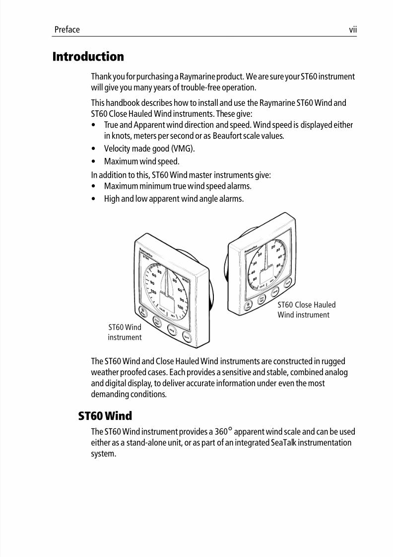
The ST60 Wind and Close Hauled Wind instruments are constructed in ruggedweather proofed cases. Each provides a sensitive and stable, combined analog
and digital display, to deliver accurate information under even the mostdemanding conditions.
ST60 Wind
The ST60 Wind instrument provides a 360° apparent wind scale and can be usedeither as a stand-alone unit, or as part of an integrated SeaTalk instrumentationsystem.
ST60 Windinstrument
ST60 Close HauledWind instrument

8/3/2019 ST60 Wind Instrument Owner's Handbook
http://slidepdf.com/reader/full/st60-wind-instrument-owners-handbook 10/52
viii ST60 Wind & Close Hauled Wind Instrument Owner’s Handbook
ST60 Close Hauled WindThe ST60 Close Hauled Wind instrument provides an expanded indication from-60° to +60° about the bow and stern of the boat, on a combined analog and
digital display.
Data inputs
SeaTalkSeaTalk enables a number of compatible instruments to operate as a single,integrated navigational system. Instruments in a SeaTalk system are linked bymeans of a single cable, which feeds both power and data. Instruments can
therefore be added to the system by plugging them into the network. SeaTalk isflexible enough to adapt to any number of compatible instruments withoutrequiring a central processor. SeaTalk can also communicate via an appropriateinterface with non-SeaTalk equipment, using the internationally-acceptedNational Marine Electronics Association (NMEA) protocol.
In a SeaTalk system, each instrument can be either a master or dedicated repeaterunit. A master instrument is directly connected to a transducer (the device thatprovides the raw data), and provides data and control for the service it is
providing to all other equipment on the SeaTalk network. A slave instrument isnot directly connected to a transducer but repeats information provided by otherequipment in the SeaTalk network.
Stand alone operationIn Stand alone operation, the ST60 Wind instrument is connected only to therelevant transducer and does not display information from, or provideinformation to, any other instruments.
Note: The ST60 Close Hauled Wind instrument operates only as a SeaTalk repeater. It can- not be connected directly to a wind transducer.
Remote control
When connected to SeaTalk, the ST60 Wind and Close Hauled Wind instrumentscan be controlled remotely by a SeaTalk Remote Keypad Unit, to provide instantremote access to the various display readouts.
8/3/2019 ST60 Wind Instrument Owner's Handbook
http://slidepdf.com/reader/full/st60-wind-instrument-owners-handbook 11/52
Preface ix
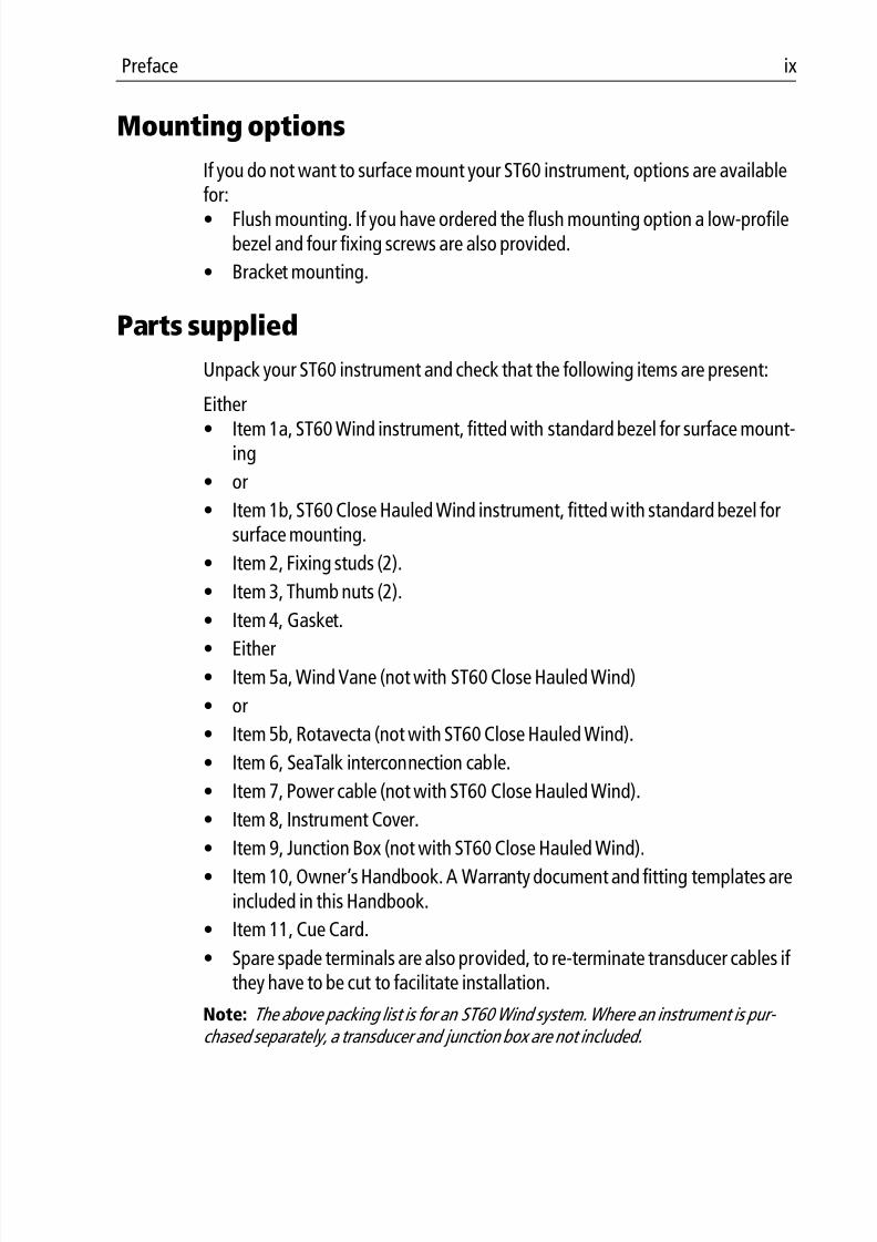
Mounting options
If you do not want to surface mount your ST60 instrument, options are availablefor:
• Flush mounting. If you have ordered the flush mounting option a low-profilebezel and four fixing screws are also provided.
• Bracket mounting.
Parts supplied
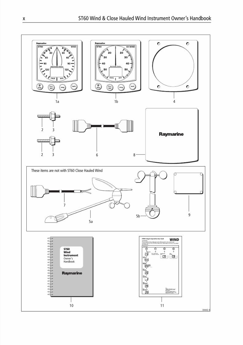
Unpack your ST60 instrument and check that the following items are present:
Either
• Item 1a, ST60 Wind instrument, fitted with standard bezel for surface mount-ing
• or
• Item 1b, ST60 Close Hauled Wind instrument, fitted with standard bezel forsurface mounting.
• Item 2, Fixing studs (2).
• Item 3, Thumb nuts (2).
• Item 4, Gasket.
• Either
• Item 5a, Wind Vane (not with ST60 Close Hauled Wind)
• or
• Item 5b, Rotavecta (not with ST60 Close Hauled Wind).
• Item 6, SeaTalk interconnection cable.
• Item 7, Power cable (not with ST60 Close Hauled Wind).
• Item 8, Instrument Cover.
• Item 9, Junction Box (not with ST60 Close Hauled Wind).• Item 10, Owner’s Handbook. A Warranty document and fitting templates are
included in this Handbook.
• Item 11, Cue Card.
• Spare spade terminals are also provided, to re-terminate transducer cables if they have to be cut to facilitate installation.
Note: The above packing list is for an ST60 Wind system. Where an instrument is pur- chased separately, a transducer and junction box are not included.
8/3/2019 ST60 Wind Instrument Owner's Handbook
http://slidepdf.com/reader/full/st60-wind-instrument-owners-handbook 12/52
x ST60 Wind & Close Hauled Wind Instrument Owner’s Handbook
D4442-4
ST60WindInstrumentOwner'sHandbook
1a 1b 4
8
9
32
32
5b
6
These items are not with ST60 Close Hauled Wind
7
1110
5a
WIND
Operation
3s to reset
*
HI
*
LO
*
TRUE APP
V MG
KTS
TACK
TRUE APP
8/3/2019 ST60 Wind Instrument Owner's Handbook
http://slidepdf.com/reader/full/st60-wind-instrument-owners-handbook 13/52
Chapter 1: Operation 1
Chapter 1: Operation
1.1 Getting started
This handbook describes how to operate, maintain and install the RaymarineST60 Wind instrument and ST60 Close Hauled Wind instrument. Theseinstruments show:• Wind speeds and directions
• Velocity Made Good (VMG) information, when boat-speed information isavailable,
• Tack angle, when heading information is available.
CAUTION: Calibration requirementThe ST60 Wind instrument and the ST60 Close Hauled Windinstrument are calibrated to factory (default) settings when firstsupplied. To ensure optimum performance on your boat, theseproducts must be calibrated before use. Do NOT use either one ofthese products until it has been calibrated using the procedures inChapter 4, Calibration .
If the CAL legend on the digital display flashes for the first 30 seconds after any
power up, use the appropriate procedures in Chapter 4, Calibration to:1. Apply the factory defaults.
2. Carry out the linearization procedure.
Displayed information
The information on the ST60 Wind and ST60 Close Hauled Wind instruments ispresented by means of a pointer and a digital display. This information can beeither true or apparent, depending on which mode is selected.
Pointer
The pointer shows the true or apparent wind direction. The scale range given bythe ST60 Wind instrument is a full 360°, whereas the ST60 Close Hauled Windinstrument gives an expanded indication from -60° to +60° about the bow orstern of the boat.
8/3/2019 ST60 Wind Instrument Owner's Handbook
http://slidepdf.com/reader/full/st60-wind-instrument-owners-handbook 14/52
2 ST60 Wind & Close Hauled Wind Instrument Owner’s Handbook
Digital display
The digital display shows the following wind and speed information:• True/apparent wind speed.
• Velocity made good (VMG).• Tack heading.
• Maximum wind speed.
• Wind alarm data.
You can select which information is displayed. When power is first switched on,the digital display shows the same type of information as was selected whenpower was last turned off.
Note: The TRUE and APP indicators flash for 8 seconds after power is switched on. This is
a function of the remote control system and can be ignored if remote control is not being used.
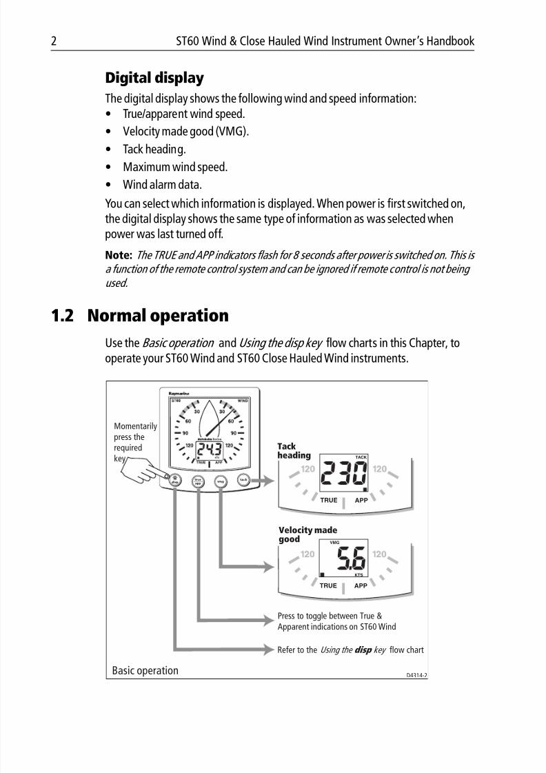
1.2 Normal operation
Use the Basic operation and Using the disp key flow charts in this Chapter, tooperate your ST60 Wind and ST60 Close Hauled Wind instruments.
TACK
TRUE APP
TRUE APP
VMG
KTS
Momentarilypress therequiredkey
Tackheading
Velocity madegood
Press to toggle between True &Apparent indications on ST60 Wind
Refer to the flow chartUsing the disp key
Basic operationD4314-2
8/3/2019 ST60 Wind Instrument Owner's Handbook
http://slidepdf.com/reader/full/st60-wind-instrument-owners-handbook 15/52
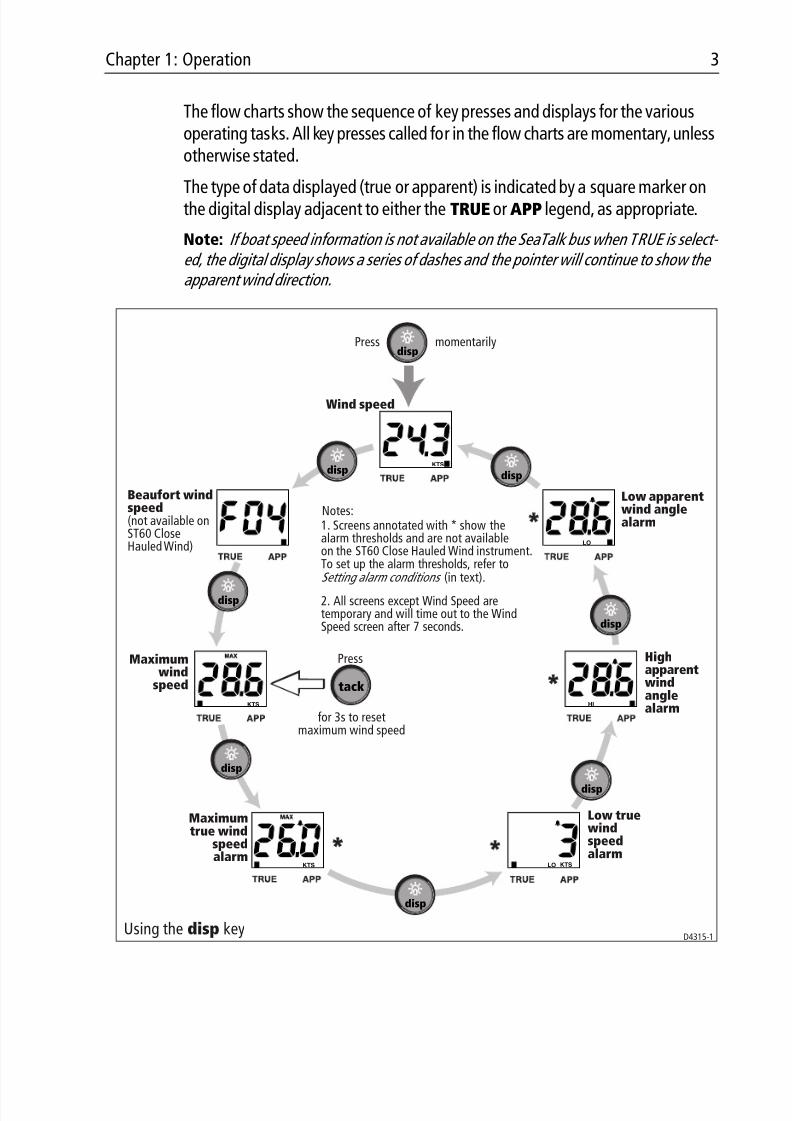
Chapter 1: Operation 3
The flow charts show the sequence of key presses and displays for the variousoperating tasks. All key presses called for in the flow charts are momentary, unlessotherwise stated.
The type of data displayed (true or apparent) is indicated by a square marker onthe digital display adjacent to either the TRUE or APP legend, as appropriate.
Note: If boat speed information is not available on the SeaTalk bus when TRUE is select- ed, the digital display shows a series of dashes and the pointer will continue to show the apparent wind direction.
Beaufort windspeed(not available onST60 CloseHauled Wind)
Maximumwind
speed
Maximumtrue wind
speedalarm
Low truewindspeedalarm
Highapparentwindanglealarm
Low apparentwind anglealarm
Wind speed
Press momentarily
Press
for 3s to resetmaximum wind speed
Using the disp key
disp
tack
1. Screens annotated with * show thealarm thresholds and are not availableon the ST60 Close Hauled Wind instrument.To set up the alarm thresholds, refer to
Setting alarm conditions (in text).
Notes:
2. All screens except Wind Speed aretemporary and will time out to the WindSpeed screen after 7 seconds.
LO
HI
LO
disp
disp
disp
disp
disp
disp
disp
D4315-1
KTSKTS
KTS
KTS
8/3/2019 ST60 Wind Instrument Owner's Handbook
http://slidepdf.com/reader/full/st60-wind-instrument-owners-handbook 16/52
4 ST60 Wind & Close Hauled Wind Instrument Owner’s Handbook
True/ApparentPress the true/app key to toggle between true and apparent instrumentreadings.
VMG
Press the vmg key to show VMG information on the digital display. The pointercontinues to show the wind direction (true or apparent as previously selected).
If boat speed information is not available on SeaTalk, the VMG cannot becomputed, and the digital display shows a series of dashes.
TackPress the tack key to show tack heading information on the digital display. Thepointer continues to show the wind angle.
If the boat speed and heading are not available on SeaTalk, the tack headingcannot be computed, and the digital display shows a series of dashes.
AlarmsAn alarm condition is indicated by a flashing alarm icon on the digital display andan audible alarm at the instrument.• When an alarm is sounding the instrument will continue to display live wind
speed and angle.
• A wind speed alarm will cause the current speed unit legend ( KTS or M/S ) toflash.
• A flashing MAX legend indicates a high wind speed alarm.
• A flashing HI legend indicates a high wind angle alarm.
• A LO legend indicates either:
• A low wind speed alarm ( LO plus speed units displayed).• A low wind angle alarm ( LO displayed).
Canceling an alarm
Pressing any key will cancel the alarm. Pressing the key repeatedly will cancel anyadditional alarms.
8/3/2019 ST60 Wind Instrument Owner's Handbook
http://slidepdf.com/reader/full/st60-wind-instrument-owners-handbook 17/52
Chapter 1: Operation 5
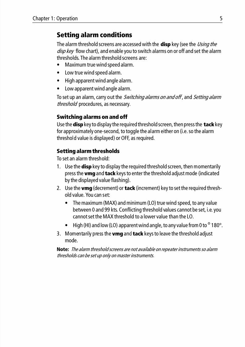
Setting alarm conditions
The alarm threshold screens are accessed with the disp key (see the Using the disp key flow chart), and enable you to switch alarms on or off and set the alarm
thresholds. The alarm threshold screens are:• Maximum true wind speed alarm.
• Low true wind speed alarm.
• High apparent wind angle alarm.
• Low apparent wind angle alarm.
To set up an alarm, carry out the Switching alarms on and off , and Setting alarm threshold procedures, as necessary.
Switching alarms on and offUse the disp key to display the required threshold screen, then press the tack keyfor approximately one-second, to toggle the alarm either on (i.e. so the alarmthreshold value is displayed) or OFF, as required.
Setting alarm thresholds
To set an alarm threshold:
1. Use the disp key to display the required threshold screen, then momentarilypress the vmg and tack keys to enter the threshold adjust mode (indicated
by the displayed value flashing).
2. Use the vmg (decrement) or tack (increment) key to set the required thresh-old value. You can set:
• The maximum (MAX) and minimum (LO) true wind speed, to any valuebetween 0 and 99 kts. Conflicting threshold values cannot be set, i.e. youcannot set the MAX threshold to a lower value than the LO.
• High (HI) and low (LO) apparent wind angle, to any value from 0 to° 180°.
3. Momentarily press the vmg and tack keys to leave the threshold adjustmode.
Note: The alarm threshold screens are not available on repeater instruments so alarm thresholds can be set up only on master instruments.
8/3/2019 ST60 Wind Instrument Owner's Handbook
http://slidepdf.com/reader/full/st60-wind-instrument-owners-handbook 18/52
6 ST60 Wind & Close Hauled Wind Instrument Owner’s Handbook
1.3 Display illumination
When the instrument is first powered up, the display illumination is set to itslowest (courtesy) level, to facilitate initial access to the keys.
To adjust the level of display illumination:
1. Hold down thedisp key for approximately one second, to enter the illumina-tion-adjust mode.
2. There are four preset illumination levels. Momentarily press thedisp key tocycle through these levels until you reach the level you want.
3. Press any other key to leave the illumination-adjust mode.
Note: The digital display will return to normal operation 7 seconds after the last key press.
1.4 Remote control
When connected to SeaTalk, the ST60 Wind and Close Hauled Wind instrumentscan be controlled remotely with a SeaTalk Remote Keypad Unit. When anyinstrument on the SeaTalk bus is selected, the TRUE/APP indicators on the digitaldisplay will flash to indicate that the keypad has control.
Details on how to use the remote control facility can be found in the SeaTalk Remote Keypad Owner ’ s Handbook .

8/3/2019 ST60 Wind Instrument Owner's Handbook
http://slidepdf.com/reader/full/st60-wind-instrument-owners-handbook 19/52
Chapter 2: Maintenance & Troubleshooting 7
Chapter 2: Maintenance & Troubleshooting
2.1 Maintenance
Servicing and safety
• Raymarine equipment should be serviced only by authorized Raymarine ser-vice technicians. They will ensure that service procedures and replacementparts used will not affect performance. There are no user serviceable parts inany Raymarine product.
• Some products generate high voltages, so never handle the cables/connec-tors when power is being supplied to the equipment.
• When powered up, all electrical equipment produces electromagnetic fields.These can cause adjacent pieces of electrical equipment to interact with oneanother, with a consequent adverse effect on operation. In order to minimizethese effects and enable you to get the best possible performance from yourRaymarine equipment, guidelines are given in the installation instructions, toenable you to ensure minimum interaction between different items of equip-ment, i.e. ensure optimum Electromagnetic Compatibility (EMC).
• Always report any EMC-related problem to your nearest Raymarine dealer.
We use such information to improve our quality standards.• In some installations, it may not be possible to prevent the equipment from
being affected by external influences. In general this will not damage theequipment but it can lead to spurious resetting action, or momentarily mayresult in faulty operation.
InstrumentCertain atmospheric conditions may cause condensation to form on the
instrument window. This will not harm the instrument and can be cleared byincreasing the illumination setting to Level 3.
Periodically clean your ST60 instrument with a soft damp cloth. Do NOT usechemical and abrasive materials to clean the instrument.
Transducer
If the wind vane is removed from its base for any reason (e.g. if the mast isstepped), use the protective cap (attached) to protect the connector on the wind
vane base.
8/3/2019 ST60 Wind Instrument Owner's Handbook
http://slidepdf.com/reader/full/st60-wind-instrument-owners-handbook 20/52
8 ST60 Wind & Close Hauled Wind Instrument Owner’s Handbook
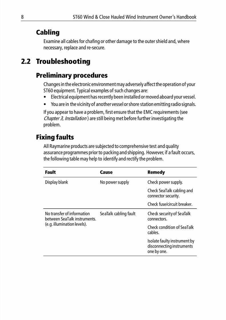
CablingExamine all cables for chafing or other damage to the outer shield and, wherenecessary, replace and re-secure.
2.2 Troubleshooting
Preliminary proceduresChanges in the electronic environment may adversely affect the operation of yourST60 equipment. Typical examples of such changes are:• Electrical equipment has recently been installed or moved aboard your vessel.
• You are in the vicinity of another vessel or shore station emitting radio signals.
If you appear to have a problem, first ensure that the EMC requirements (seeChapter 3, Installation ) are still being met before further investigating theproblem.
Fixing faults
All Raymarine products are subjected to comprehensive test and qualityassurance programmes prior to packing and shipping. However, if a fault occurs,the following table may help to identify and rectify the problem.
Fault Cause Remedy
Display blank No power supply Check power supply.
Check SeaTalk cabling andconnector security.
Check fuse/circuit breaker.
No transfer of information
between SeaTalk instruments.(e.g. illumination levels).
SeaTalk cabling fault Check security of SeaTalk
connectors.
Check condition of SeaTalkcables.
Isolate faulty instrument bydisconnecting instrumentsone by one.

8/3/2019 ST60 Wind Instrument Owner's Handbook
http://slidepdf.com/reader/full/st60-wind-instrument-owners-handbook 21/52
Chapter 2: Maintenance & Troubleshooting 9
Technical supportRaymarine provides a comprehensive customer support service, on the worldwide web and by telephone help line. Please use either of these facilities if you are
unable to rectify a problem.
World wide web
Please visit the Customer Support area of our web site at:• www.raymarine.com
As well as providing a comprehensive Frequently Asked Questions section andservicing information, the web site gives e-mail access to the Raymarine TechnicalSupport Department and a details of the locations of Raymarine agents,
worldwide.
Telephone help line
If you do not have access to the world wide web, please call our help line.
In the USA, call:• +1 800 539 5539, extension 2444 or
• +1 603 881 5200 extension 2444
In the UK, Europe the Middle East or the Far East, call:
• +44 (0) 23 9271 4713 (voice)• +44 (0) 23 9266 1228 (fax)
Help us to help you
When requesting service, please quote the following product information:• Equipment type.
• Model number.
• Serial number.
• Software issue number.
The Software issue number can be ascertained by means of the IntermediateCalibration facility, see Chapter 4, Calibration .

8/3/2019 ST60 Wind Instrument Owner's Handbook
http://slidepdf.com/reader/full/st60-wind-instrument-owners-handbook 22/52
10 ST60 Wind & Close Hauled Wind Instrument Owner’s Handbook
8/3/2019 ST60 Wind Instrument Owner's Handbook
http://slidepdf.com/reader/full/st60-wind-instrument-owners-handbook 23/52
Chapter 3: Installation 11
Chapter 3: InstallationThis chapter describes how to install the ST60 Wind and ST60 Close Hauled Windinstruments, and associated wind transducer.
You can use any one of three Raymarine wind transducer types in conjunctionwith the ST60 Wind instruments:• Cruiser wind vane (short arm). Typically mounted on a mast head.
• Competition wind vane (long arm). Typically mounted on a mast head.
• Rotavecta. Typically mounted on a rail or radar arch.
The transducer is connected to the rear of the instrument.
Note: The ST60 Close Hauled Wind instrument does not connect directly to a wind trans-
ducer.For advice, or further information regarding the installation of this equipment,please contact the Raymarine Product Support Department or your own NationalDistributor.
3.1 Planning your installation
Before starting the installation, spend some time considering the best positionsfor both transducer and instrument, such that the Site requirements and the EMC installation guidelines are satisfied.
Site requirements
Transducers
Each transducer type has a cable connected, and is supplied with a junction boxand a set of spade terminals.
The transducer location must:• Allow reasonable access for installation and servicing.
• Be as high as possible and away from any equipment which may shield thetransducer or otherwise disturb the air flow.
• Provide a horizontal mounting surface. If a surface (e.g. mast top) is otherwisesuitable but not horizontal, make up a suitable wedged packing piece to pro-vide the necessary horizontal surface.
There must also be a viable route for the transducer cable to be routed to theinstrument.
8/3/2019 ST60 Wind Instrument Owner's Handbook
http://slidepdf.com/reader/full/st60-wind-instrument-owners-handbook 24/52
12 ST60 Wind & Close Hauled Wind Instrument Owner’s Handbook
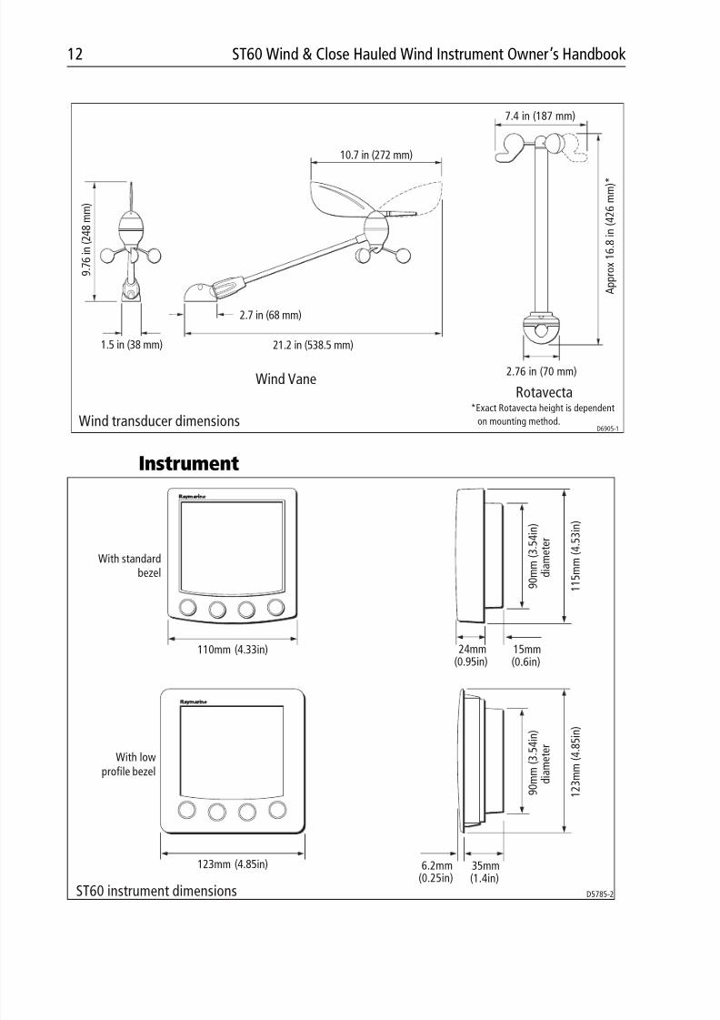
Instrument
2.7 in (68 mm)
1.5 in (38 mm)
D6905-1
9 . 7
6 i n ( 2 4 8 m m )
10.7 in (272 mm)
21.2 in (538.5 mm)
7.4 in (187 mm)
A p p r o x 1 6 . 8
i n ( 4 2 6 m m ) *
2.76 in (70 mm)Wind Vane
Rotavecta*Exact Rotavecta height is dependent
on mounting method.Wind transducer dimensions
110mm (4.33in) 24mm(0.95in)
15mm(0.6in)
9 0 m m ( 3 . 5
4 i n )
d i a m e t e r
1 1 5 m m ( 4 . 5
3 i n )
123mm (4.85in) 6.2mm(0.25in)
35mm(1.4in)
9 0 m m ( 3 . 5
4 i n )
d i a m e t e r
1 2 3 m m ( 4 . 8
5 i n )
D5785-2ST60 instrument dimensions
With standardbezel
With lowprofile bezel

8/3/2019 ST60 Wind Instrument Owner's Handbook
http://slidepdf.com/reader/full/st60-wind-instrument-owners-handbook 25/52
Chapter 3: Installation 13
CAUTION:The presence of moisture at the rear of the instrument could causedamage either by entering the instrument through the breathinghole or by coming into contact with the electrical connectors.
ST60 instruments can be fitted either above or below deck, provided the rear of the instrument is sited where it is protected from contact with water.
Each instrument must also be positioned where:• It is easily read by the helmsman
• It is protected against physical damage
• It is at least 9 in (230 mm) from a compass
• It is at least 20 in (500 mm) from radio receiving equipment
• There is reasonable rear access for installation and servicing
EMC installation guidelinesAll Raymarine equipment and accessories are designed to the best industrystandards for use in the recreational marine environment.
Their design and manufacture conforms to the appropriate ElectromagneticCompatibility (EMC) standards, but correct installation is required to ensure thatperformance is not compromised. Although every effort has been taken to ensure
that they will perform under all conditions, it is important to understand whatfactors could affect the operation of the product.
The guidelines given here describe the conditions for optimum EMC performance,but it is recognized that it may not be possible to meet all of these conditions in allsituations. To ensure the best possible conditions for EMC performance within theconstraints imposed by any location, always ensure the maximum separationpossible between different items of electrical equipment.
For optimum EMC performance, it is recommended that wherever possible:• Raymarine equipment and cables connected to it are:
• At least 3 ft (1 m) from any equipment transmitting or cables carryingradio signals e.g. VHF radios, cables and antennas. In the case of SSBradios, the distance should be increased to 7 ft (2 m).
• More than 7 ft (2 m) from the path of a radar beam. A radar beam can nor-mally be assumed to spread 20 degrees above and below the radiatingelement.
• The equipment is supplied from a separate battery from that used for engine
start. Voltage drops below 10 V in the power supply to our products, andstarter motor transients, can cause the equipment to reset. This will not dam-
8/3/2019 ST60 Wind Instrument Owner's Handbook
http://slidepdf.com/reader/full/st60-wind-instrument-owners-handbook 26/52
14 ST60 Wind & Close Hauled Wind Instrument Owner’s Handbook
age the equipment, but may cause the loss of some information and maychange the operating mode.
• Raymarine specified cables are used. Cutting and rejoining these cables cancompromise EMC performance and must be avoided unless doing so isdetailed in the installation manual.
• If a suppression ferrite is attached to a cable, this ferrite should not beremoved. If the ferrite needs to be removed during installation it must be reas-sembled in the same position.
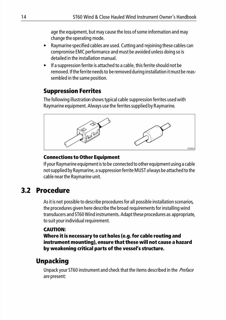
Suppression Ferrites
The following illustration shows typical cable suppression ferrites used withRaymarine equipment. Always use the ferrites supplied by Raymarine.
Connections to Other Equipment
If your Raymarine equipment is to be connected to other equipment using a cablenot supplied by Raymarine, a suppression ferrite MUST always be attached to thecable near the Raymarine unit.
3.2 Procedure
As it is not possible to describe procedures for all possible installation scenarios,the procedures given here describe the broad requirements for installing windtransducers and ST60 Wind instruments. Adapt these procedures as appropriate,
to suit your individual requirement.
CAUTION:Where it is necessary to cut holes (e.g. for cable routing andinstrument mounting), ensure that these will not cause a hazardby weakening critical parts of the vessel’s structure.
Unpacking
Unpack your ST60 instrument and check that the items described in the Preface
are present:
D3548-6
8/3/2019 ST60 Wind Instrument Owner's Handbook
http://slidepdf.com/reader/full/st60-wind-instrument-owners-handbook 27/52
Chapter 3: Installation 15
Each ST60 instrument is supplied with a standard bezel for surface mounting.Optional mounting kits are available for flush mounting and bracket mountingthe instrument. If you have ordered the flush mounting option a low-profile bezeland four fixing screws are also provided.
Fitting the instrumentsThe ST60 Wind and ST60 Close Hauled Wind instruments can be installed usingone of a number of different mounting options:• Surface mounting. Gives a profile of approximately 0.95 in (24 mm).
• Flush mounting. Gives a profile of approximately 0.25 in (6 mm).
• Bracket mounting.
The ST60 instruments can also be mounted behind a panel with just theinstrument dial and keys visible.
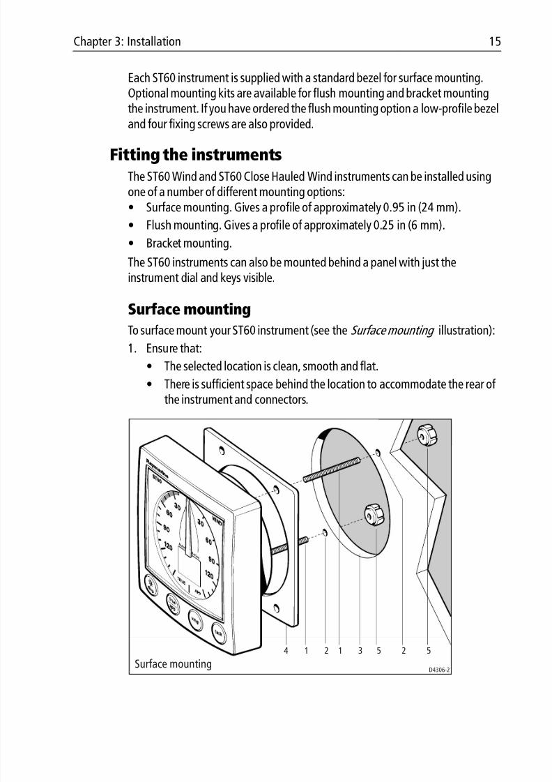
Surface mounting
To surface mount your ST60 instrument (see the Surface mounting illustration):
1. Ensure that:
• The selected location is clean, smooth and flat.
• There is sufficient space behind the location to accommodate the rear of
the instrument and connectors.
Surface mounting D4306-2
1 12 234 5 5
8/3/2019 ST60 Wind Instrument Owner's Handbook
http://slidepdf.com/reader/full/st60-wind-instrument-owners-handbook 28/52
16 ST60 Wind & Close Hauled Wind Instrument Owner’s Handbook
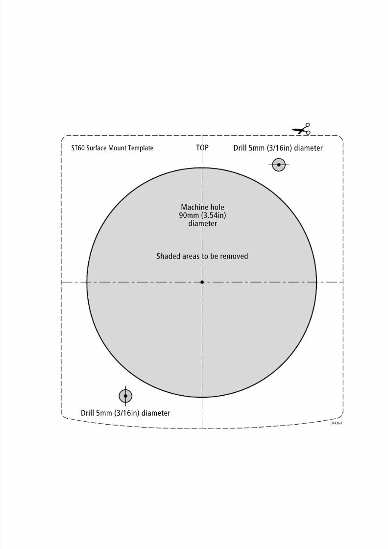
2. Apply the surface mount template (supplied at the rear of this handbook) tothe selected location and mark the centers for the fixing studs (1) and theaperture (3) that will take the rear casing of the instrument.
3. Drill out the two 0.2 in (5 mm) fixing stud clearance holes (2).
4. Cut out the clearance hole (3) then remove the template.
5. Peel off the protective sheet from the self-adhesive gasket (4) then stick thegasket into position on the rear of the instrument.
6. Screw the two fixing studs into the threaded sockets on the rear of the instru-ment.
7. Mount the assembled instrument, studs, bezel and gasket into the panel.Secure from behind with the thumb nuts (5).
Flush mounting
The Flush Mounting Kit uses a low-profile bezel to reduce the fitted profile of theinstrument, to approximately 0.25 in (6 mm) above the panel fascia.
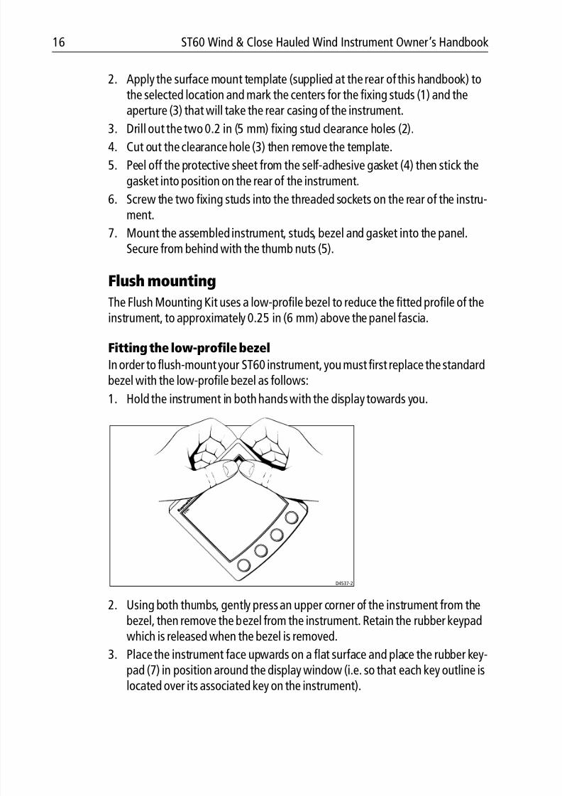
Fitting the low-profile bezel
In order to flush-mount your ST60 instrument, you must first replace the standardbezel with the low-profile bezel as follows:
1. Hold the instrument in both hands with the display towards you.
2. Using both thumbs, gently press an upper corner of the instrument from thebezel, then remove the bezel from the instrument. Retain the rubber keypadwhich is released when the bezel is removed.
3. Place the instrument face upwards on a flat surface and place the rubber key-pad (7) in position around the display window (i.e. so that each key outline is
located over its associated key on the instrument).
D4537-2
8/3/2019 ST60 Wind Instrument Owner's Handbook
http://slidepdf.com/reader/full/st60-wind-instrument-owners-handbook 29/52
Chapter 3: Installation 17
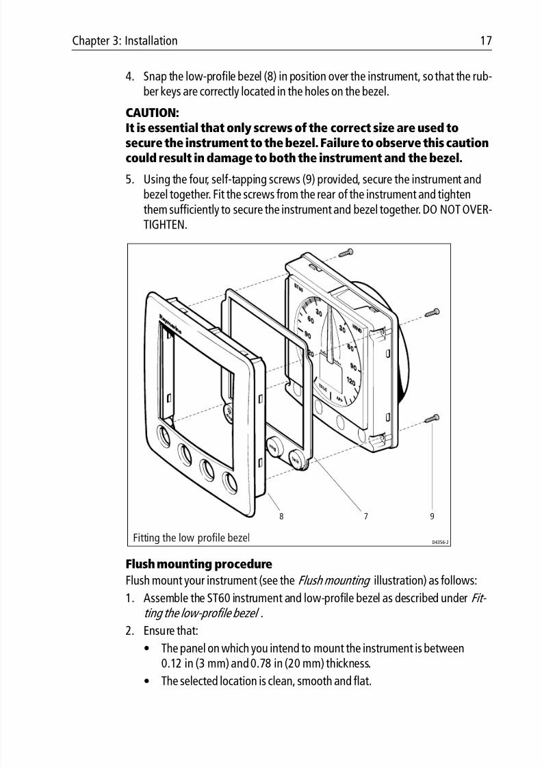
4. Snap the low-profile bezel (8) in position over the instrument, so that the rub-ber keys are correctly located in the holes on the bezel.
CAUTION:
It is essential that only screws of the correct size are used tosecure the instrument to the bezel. Failure to observe this cautioncould result in damage to both the instrument and the bezel.
5. Using the four, self-tapping screws (9) provided, secure the instrument andbezel together. Fit the screws from the rear of the instrument and tightenthem sufficiently to secure the instrument and bezel together. DO NOT OVER-TIGHTEN.
Flush mounting procedure
Flush mount your instrument (see the Flush mounting illustration) as follows:
1. Assemble the ST60 instrument and low-profile bezel as described under Fit- ting the low-profile bezel .
2. Ensure that:
• The panel on which you intend to mount the instrument is between0.12 in (3 mm) and 0.78 in (20 mm) thickness.
• The selected location is clean, smooth and flat.
D4356-2
78 9
Fitting the low profile bezel
8/3/2019 ST60 Wind Instrument Owner's Handbook
http://slidepdf.com/reader/full/st60-wind-instrument-owners-handbook 30/52
18 ST60 Wind & Close Hauled Wind Instrument Owner’s Handbook
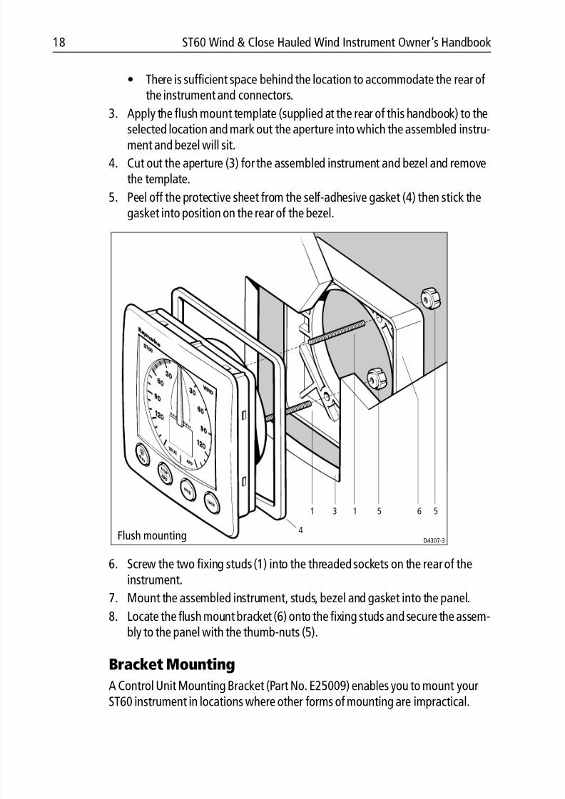
• There is sufficient space behind the location to accommodate the rear of the instrument and connectors.
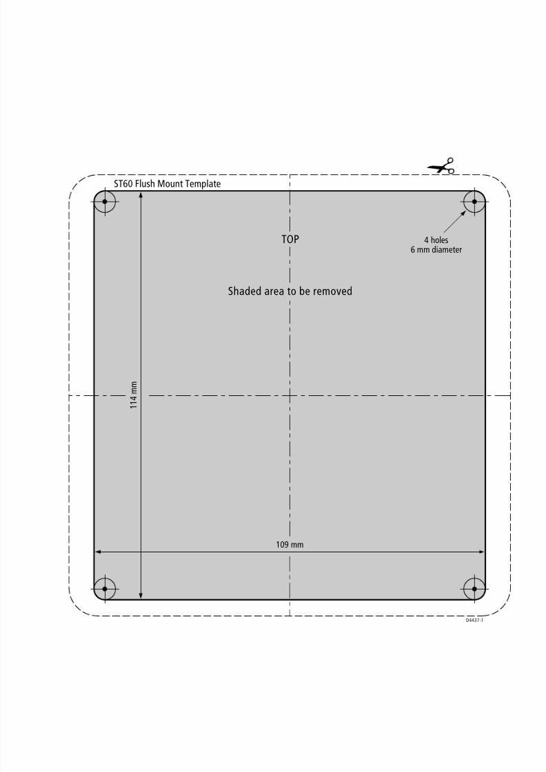
3. Apply the flush mount template (supplied at the rear of this handbook) to theselected location and mark out the aperture into which the assembled instru-ment and bezel will sit.
4. Cut out the aperture (3) for the assembled instrument and bezel and removethe template.
5. Peel off the protective sheet from the self-adhesive gasket (4) then stick thegasket into position on the rear of the bezel.
6. Screw the two fixing studs (1) into the threaded sockets on the rear of theinstrument.
7. Mount the assembled instrument, studs, bezel and gasket into the panel.
8. Locate the flush mount bracket (6) onto the fixing studs and secure the assem-bly to the panel with the thumb-nuts (5).
Bracket Mounting
A Control Unit Mounting Bracket (Part No. E25009) enables you to mount yourST60 instrument in locations where other forms of mounting are impractical.
D4307-3Flush mounting
1 13
4
5 56
8/3/2019 ST60 Wind Instrument Owner's Handbook
http://slidepdf.com/reader/full/st60-wind-instrument-owners-handbook 31/52
Chapter 3: Installation 19
Although this provides a useful alternative method for securing your instrument,it is only suitable for use in positions where the instrument will not be exposed towater.
To bracket mount your ST60 instrument, do so in accordance with the Control UnitMounting Bracket Instruction Sheet.
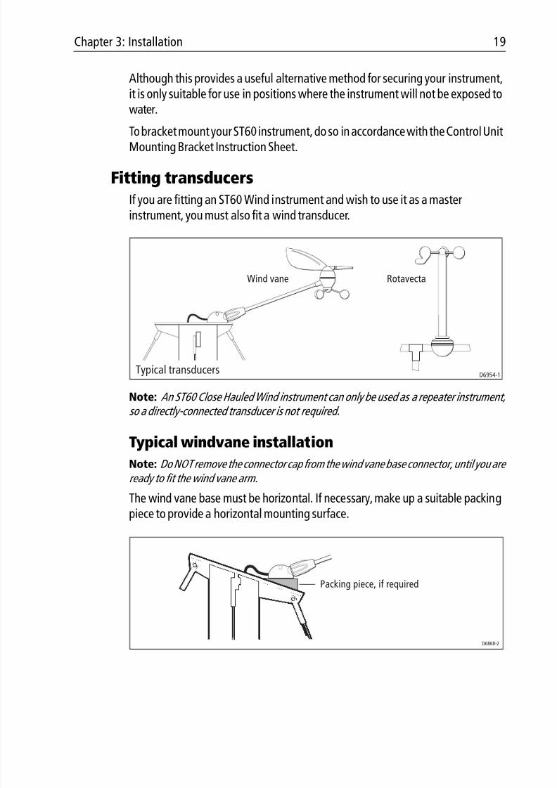
Fitting transducersIf you are fitting an ST60 Wind instrument and wish to use it as a masterinstrument, you must also fit a wind transducer.
Note: An ST60 Close Hauled Wind instrument can only be used as a repeater instrument,so a directly-connected transducer is not required.
Typical windvane installation
Note: Do NOT remove the connector cap from the wind vane base connector, until you are ready to fit the wind vane arm.
The wind vane base must be horizontal. If necessary, make up a suitable packingpiece to provide a horizontal mounting surface.
D6954-1
RotavectaWind vane
Typical transducers
Packing piece, if required
D6868-2
8/3/2019 ST60 Wind Instrument Owner's Handbook
http://slidepdf.com/reader/full/st60-wind-instrument-owners-handbook 32/52
20 ST60 Wind & Close Hauled Wind Instrument Owner’s Handbook
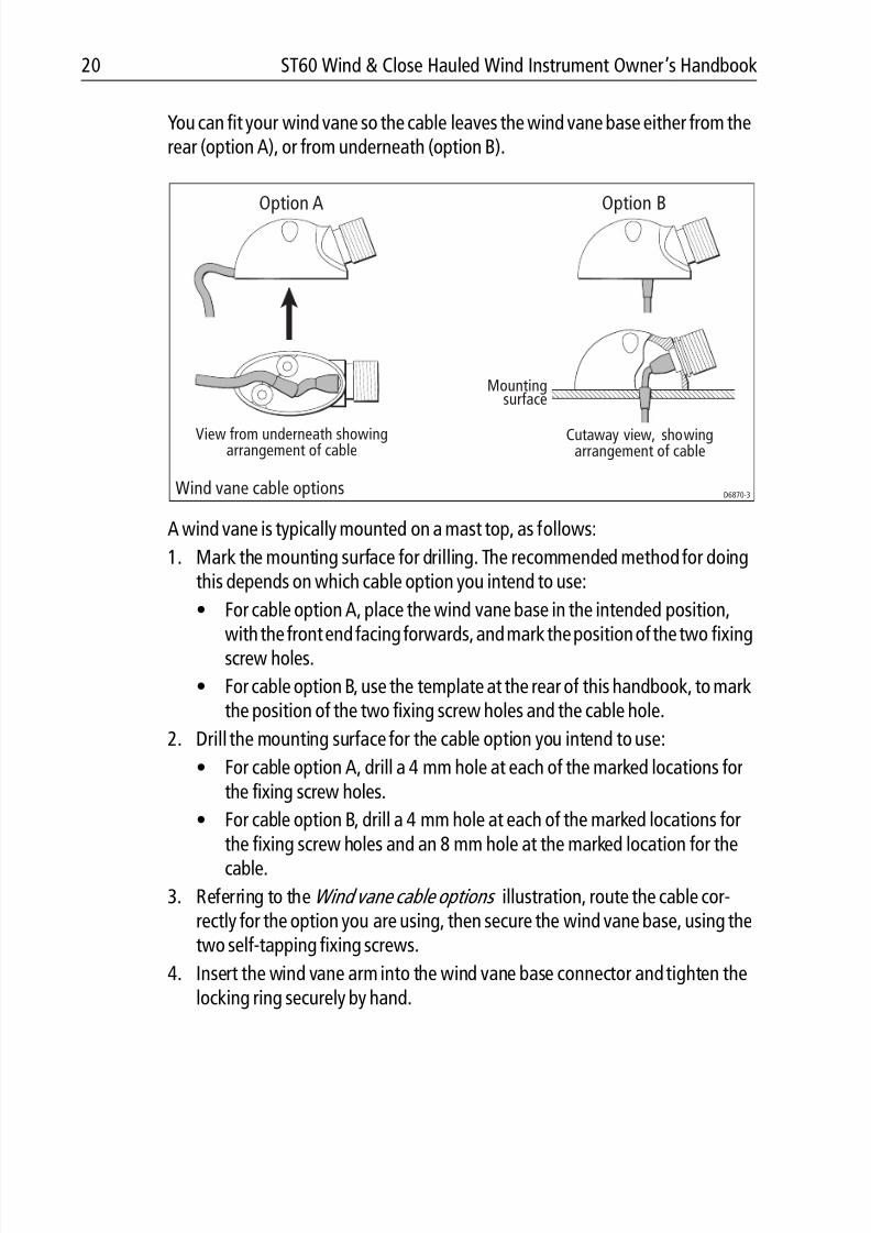
You can fit your wind vane so the cable leaves the wind vane base either from therear (option A), or from underneath (option B).
A wind vane is typically mounted on a mast top, as follows:
1. Mark the mounting surface for drilling. The recommended method for doingthis depends on which cable option you intend to use:
• For cable option A, place the wind vane base in the intended position,
with the front end facing forwards, and mark the position of the two fixingscrew holes.
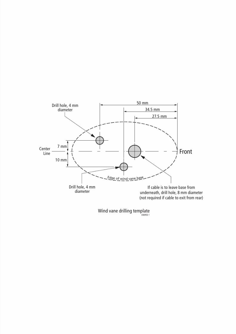
• For cable option B, use the template at the rear of this handbook, to markthe position of the two fixing screw holes and the cable hole.
2. Drill the mounting surface for the cable option you intend to use:
• For cable option A, drill a 4 mm hole at each of the marked locations forthe fixing screw holes.
• For cable option B, drill a 4 mm hole at each of the marked locations for
the fixing screw holes and an 8 mm hole at the marked location for thecable.
3. Referring to the Wind vane cable options illustration, route the cable cor-rectly for the option you are using, then secure the wind vane base, using thetwo self-tapping fixing screws.
4. Insert the wind vane arm into the wind vane base connector and tighten thelocking ring securely by hand.
View from underneath showingarrangement of cable
Cutaway view, showingarrangement of cable
Option A Option B
D6870-3Wind vane cable options
Mountingsurface
8/3/2019 ST60 Wind Instrument Owner's Handbook
http://slidepdf.com/reader/full/st60-wind-instrument-owners-handbook 33/52
Chapter 3: Installation 21
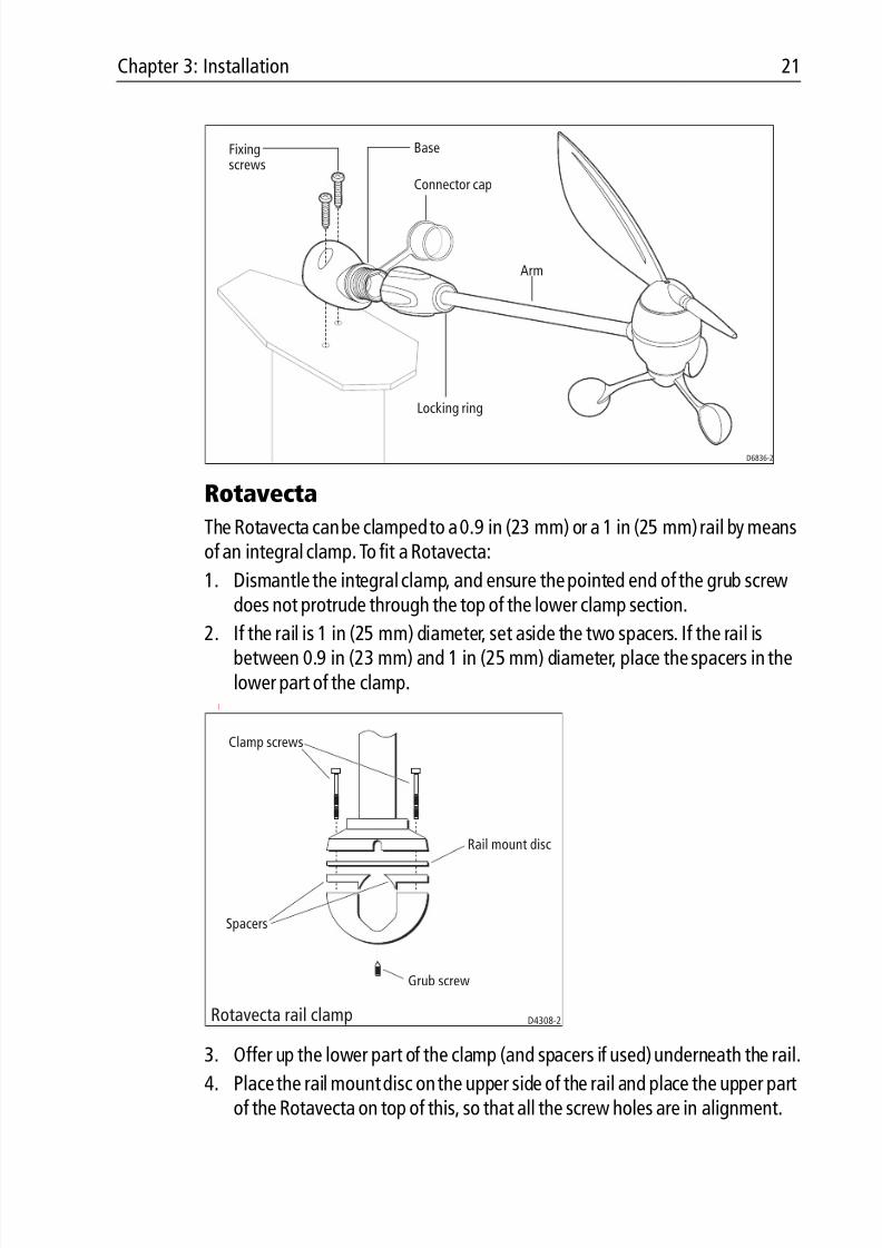
Rotavecta
The Rotavecta can be clamped to a 0.9 in (23 mm) or a 1 in (25 mm) rail by meansof an integral clamp. To fit a Rotavecta:
1. Dismantle the integral clamp, and ensure the pointed end of the grub screwdoes not protrude through the top of the lower clamp section.
2. If the rail is 1 in (25 mm) diameter, set aside the two spacers. If the rail isbetween 0.9 in (23 mm) and 1 in (25 mm) diameter, place the spacers in thelower part of the clamp.
[
3. Offer up the lower part of the clamp (and spacers if used) underneath the rail.
4. Place the rail mount disc on the upper side of the rail and place the upper partof the Rotavecta on top of this, so that all the screw holes are in alignment.
D6836-2
Base
Connector cap
Locking ring
Fixingscrews
Arm
Clamp screws
Rail mount disc
Spacers
Grub screw
Rotavecta rail clamp D4308-2
8/3/2019 ST60 Wind Instrument Owner's Handbook
http://slidepdf.com/reader/full/st60-wind-instrument-owners-handbook 34/52
22 ST60 Wind & Close Hauled Wind Instrument Owner’s Handbook
5. Secure all sections together using the two fixing screws, but do not fullytighten at this stage.
6. Ensure the main shaft of the Rotavecta is vertical, then tighten the two fixingscrews.
7. Screw in the grub screw, to pinch the rail.
Running transducer cable
General
Each transducer type is supplied with sufficient cable already connected, to runfrom the mounted position to the ST60 Wind instrument. The manner in whichyou run the cable will depend on the locations of the transducer and instrument.
Observing the following guidelines, run the transducer cable to the instrument:• If the cable has to be fed through the deck, always use a proprietary deck
gland.
• Where cables are fed through holes, always use grommets to prevent chafing.
• Secure long cable runs so they do not present a hazard.
• If the transducer is mounted on a masthead or other structure likely to beremoved for maintenance or storage purposes (e.g. a mast), always incorpo-rate a junction box into the cable run as close as possible to the cable entry
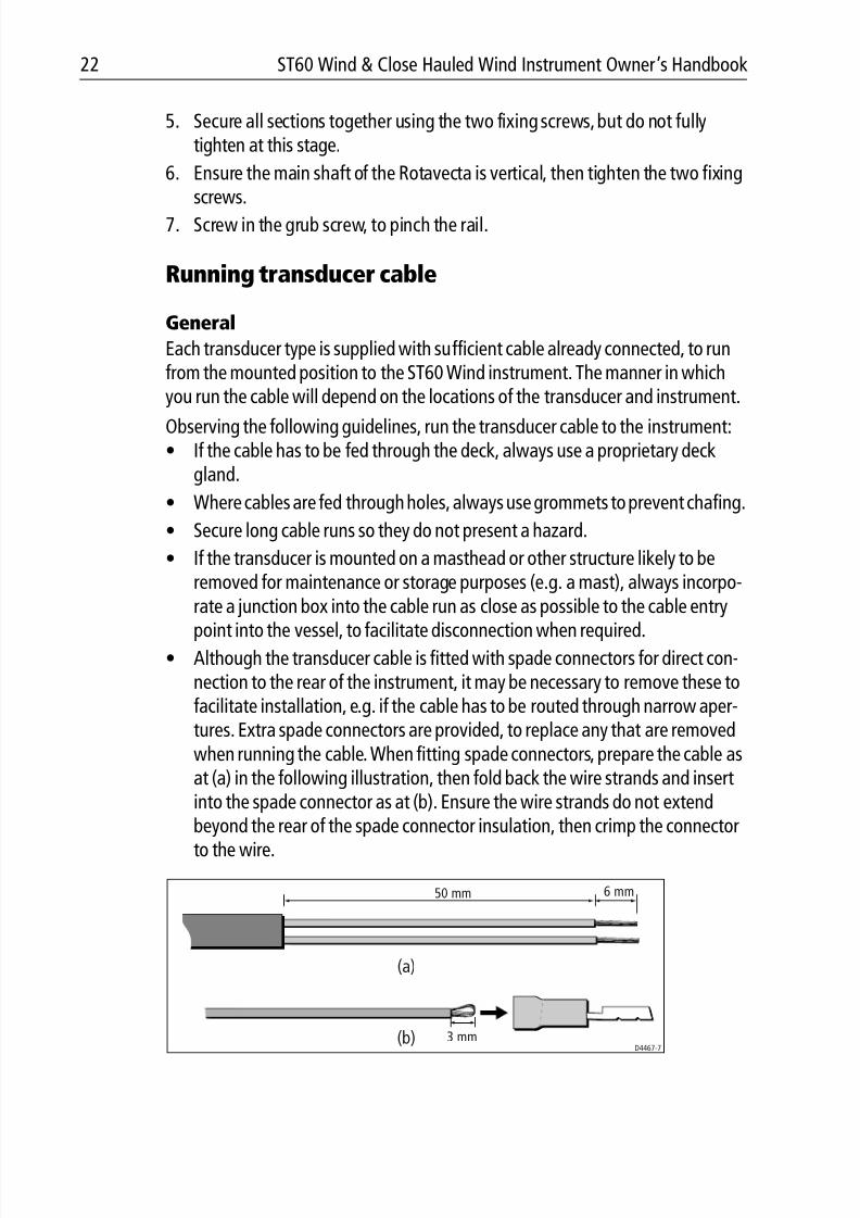
point into the vessel, to facilitate disconnection when required.• Although the transducer cable is fitted with spade connectors for direct con-
nection to the rear of the instrument, it may be necessary to remove these tofacilitate installation, e.g. if the cable has to be routed through narrow aper-tures. Extra spade connectors are provided, to replace any that are removedwhen running the cable. When fitting spade connectors, prepare the cable asat (a) in the following illustration, then fold back the wire strands and insertinto the spade connector as at (b). Ensure the wire strands do not extend
beyond the rear of the spade connector insulation, then crimp the connectorto the wire.
3 mm
6 mm50 mm
(a)
(b) D4467-7
8/3/2019 ST60 Wind Instrument Owner's Handbook
http://slidepdf.com/reader/full/st60-wind-instrument-owners-handbook 35/52
Chapter 3: Installation 23
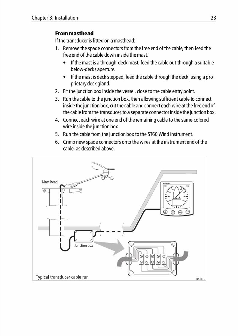
From masthead
If the transducer is fitted on a masthead:
1. Remove the spade connectors from the free end of the cable, then feed the
free end of the cable down inside the mast.• If the mast is a through-deck mast, feed the cable out through a suitable
below-decks aperture.
• If the mast is deck stepped, feed the cable through the deck, using a pro-prietary deck gland.
2. Fit the junction box inside the vessel, close to the cable entry point.
3. Run the cable to the junction box, then allowing sufficient cable to connectinside the junction box, cut the cable and connect each wire at the free end of
the cable from the transducer, to a separate connector inside the junction box.4. Connect each wire at one end of the remaining cable to the same-coloredwire inside the junction box.
5. Run the cable from the junction box to the ST60 Wind instrument.
6. Crimp new spade connectors onto the wires at the instrument end of thecable, as described above.
Mast head
Junction box
Typical transducer cable run D4313-3
8/3/2019 ST60 Wind Instrument Owner's Handbook
http://slidepdf.com/reader/full/st60-wind-instrument-owners-handbook 36/52
24 ST60 Wind & Close Hauled Wind Instrument Owner’s Handbook
Connecting the instruments
Types of connection
The ST60 Wind instrument and the ST60 Close Hauled Wind instrument can eachbe connected to SeaTalk, as repeater instruments.
The ST60 Wind instrument, can also be connected:• As a stand-alone instrument connected directly to the wind transducer.
• To fulfil both repeater and master roles by being connected both to the trans-ducer and to SeaTalk.
Instruments connected to SeaTalk derive their power directly from SeaTalk and noseparate power connection is necessary. Where a SeaTalk system includes an
autopilot, the power for the system is provided by the autopilot.
A range of Raymarine SeaTalk extension cables is available to connect separatedinstruments. These cables are supplied with a SeaTalk connector fitted to eachend. A junction box can be used to join cables.
Signal connections
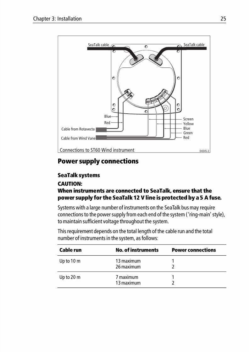
Make the necessary connections to your ST60 instrument (see the Connection to ST60 Wind instrument illustration). Although all possible connections are shown:
• You can connect only one transducer type (either Rotavecta or Wind Vane), toan ST60 Wind instrument. Do NOT attempt to connect both types, even if bothare fitted.
Note: If at any time, the transducer type is changed (e.g. a Wind Vane is connected in place of a Rotavecta), use the procedures in Chapter 4, Calibration to apply the factory de- fault settings, then carry out the linearization and alignment procedures.
• The ST60 Close Hauled Wind instrument can only be connected to SeaTalk; itdoes not have transducer connectors.
8/3/2019 ST60 Wind Instrument Owner's Handbook
http://slidepdf.com/reader/full/st60-wind-instrument-owners-handbook 37/52
Chapter 3: Installation 25
Power supply connections
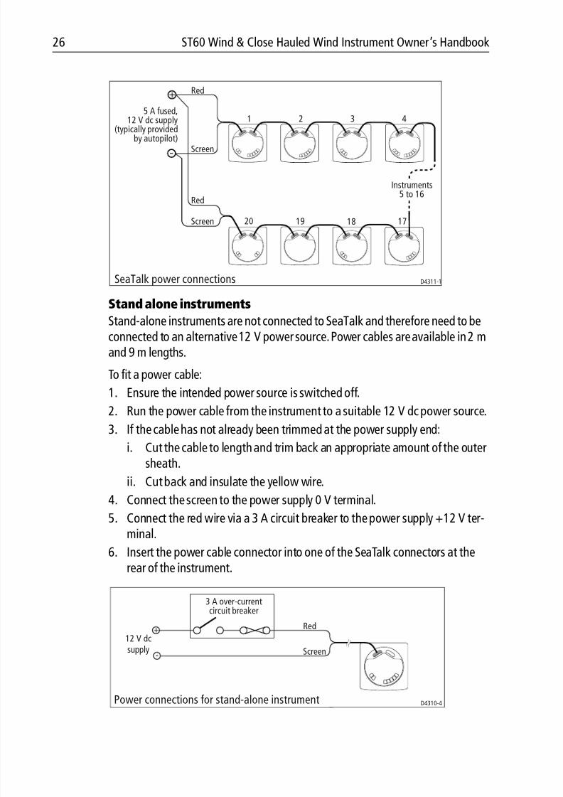
SeaTalk systems
CAUTION:When instruments are connected to SeaTalk, ensure that thepower supply for the SeaTalk 12 V line is protected by a 5 A fuse.
Systems with a large number of instruments on the SeaTalk bus may requireconnections to the power supply from each end of the system (‘ring-main’ style),to maintain sufficient voltage throughout the system.
This requirement depends on the total length of the cable run and the totalnumber of instruments in the system, as follows:
Cable run No. of instruments Power connections
Up to 10 m 13 maximum26 maximum
12
Up to 20 m 7 maximum13 maximum
12
D4345-2
Blue
Red
Green
YellowScreen
Cable from Rotavecta
Cable from Wind Vane
SeaTalk cable SeaTalk cable
Connections to ST60 Wind instrument
Blue
Red
8/3/2019 ST60 Wind Instrument Owner's Handbook
http://slidepdf.com/reader/full/st60-wind-instrument-owners-handbook 38/52
26 ST60 Wind & Close Hauled Wind Instrument Owner’s Handbook
Stand alone instruments
Stand-alone instruments are not connected to SeaTalk and therefore need to beconnected to an alternative 12 V power source. Power cables are available in 2 mand 9 m lengths.
To fit a power cable:
1. Ensure the intended power source is switched off.
2. Run the power cable from the instrument to a suitable 12 V dc power source.3. If the cable has not already been trimmed at the power supply end:
i. Cut the cable to length and trim back an appropriate amount of the outersheath.
ii. Cut back and insulate the yellow wire.
4. Connect the screen to the power supply 0 V terminal.
5. Connect the red wire via a 3 A circuit breaker to the power supply +12 V ter-minal.
6. Insert the power cable connector into one of the SeaTalk connectors at therear of the instrument.
D4311-1
5 A fused,12 V dc supply
(typically providedby autopilot)
Red
Screen
Red
Screen
1 2 3 4
Instruments5 to 16
17181920
SeaTalk power connections
Power connections for stand-alone instrument
12 V dcsupply
3 A over-currentcircuit breaker
Red
Screen
D4310-4
8/3/2019 ST60 Wind Instrument Owner's Handbook
http://slidepdf.com/reader/full/st60-wind-instrument-owners-handbook 39/52
Chapter 4: Calibration 27
Chapter 4: Calibration
4.1 Introduction
The ST60 Wind instruments are set up with factory-programmed default settings,so in order to optimize the performance of the instruments on board a particularvessel, the procedures in this Chapter must be carried out immediately after thecompletion of installation, and before the equipment is used for navigationalpurposes.
Where practicable, the calibration procedures are presented diagrammatically toshow the sequence of key presses and the resulting displays. Adjustment
instructions are given as applicable.
EMC conformance
• Always check the installation before going to sea to make sure that it is notaffected by radio transmissions, engine starting etc.
• In some installations, it may not be possible to prevent the equipment frombeing affected by external influences. Although this will not damage theequipment, it can lead to spurious resetting action, or momentarily may result
in faulty operation.
4.2 User calibration
The User calibration procedures:• Linearize and align the wind transducer.
• Select the required wind speed units
Linearizing and aligning the wind transducerThis procedure ensures that the sensors in the windvane transducer are correctlycalibrated to record rotation of the windvane, then compensates for any smallerrors which may exist in the alignment of the wind transducer.
To do this:
1. Power-up the ST60 Wind instrument.
2. Slowly turn the vessel through two complete circles. This procedure automat-ically linearizes the windvane. A successful linearization is indicated by the
digital display flashing and the buzzer sounding three beeps.
8/3/2019 ST60 Wind Instrument Owner's Handbook
http://slidepdf.com/reader/full/st60-wind-instrument-owners-handbook 40/52
28 ST60 Wind & Close Hauled Wind Instrument Owner’s Handbook
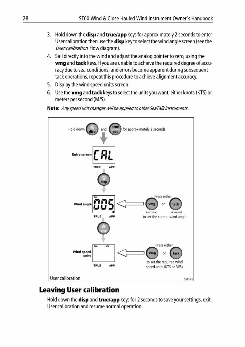
3. Hold down thedispandtrue/appkeys for approximately 2 seconds to enterUser calibration then use the disp key to select the wind angle screen (see theUser calibration flow diagram).
4. Sail directly into the wind and adjust the analog pointer to zero, using thevmg and tack keys. If you are unable to achieve the required degree of accu-racy due to sea conditions, and errors become apparent during subsequenttack operations, repeat this procedure to achieve alignment accuracy.
5. Display the wind speed units screen.
6. Use the vmgandtack keys to select the units you want, either knots (KTS) ormeters per second (M/S).
Note: Any speed unit changes will be applied to other SeaTalk instruments.
Leaving User calibration
Hold down the disp and true/app keys for 2 seconds to save your settings, exitUser calibration and resume normal operation.
Hold down and for approximately 2 secondsdisp
true
app
Entry screen
Wind angle
disp
Wind speedunits
TRUE APP
TRUE APP
TRUE APP
vmg tack
vmg tack
Press either
or
(decrease) (increase)
to set the current wind angle
Press either
or
to set the required windspeed units (KTS or M/S)
User calibration D4316-1
8/3/2019 ST60 Wind Instrument Owner's Handbook
http://slidepdf.com/reader/full/st60-wind-instrument-owners-handbook 41/52
Chapter 4: Calibration 29
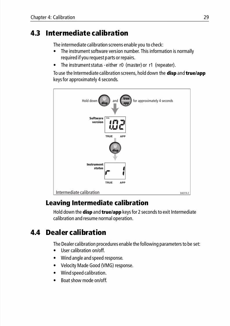
4.3 Intermediate calibration
The intermediate calibration screens enable you to check:• The instrument software version number. This information is normally
required if you request parts or repairs.
• The instrument status - either r0 (master) or r1 (repeater).
To use the Intermediate calibration screens, hold down the disp and true/app keys for approximately 4 seconds.
Leaving Intermediate calibrationHold down the disp and true/app keys for 2 seconds to exit Intermediatecalibration and resume normal operation.
4.4 Dealer calibration
The Dealer calibration procedures enable the following parameters to be set:• User calibration on/off.
• Wind angle and speed response.
• Velocity Made Good (VMG) response.
• Wind speed calibration.
• Boat show mode on/off.
Hold down and for approximately 4 secondsdisp
true
app
Softwareversion
Instrument
status
disp
Intermediate calibration D4319-2
CAL
TRUE APP
TRUE APP
8/3/2019 ST60 Wind Instrument Owner's Handbook
http://slidepdf.com/reader/full/st60-wind-instrument-owners-handbook 42/52
30 ST60 Wind & Close Hauled Wind Instrument Owner’s Handbook
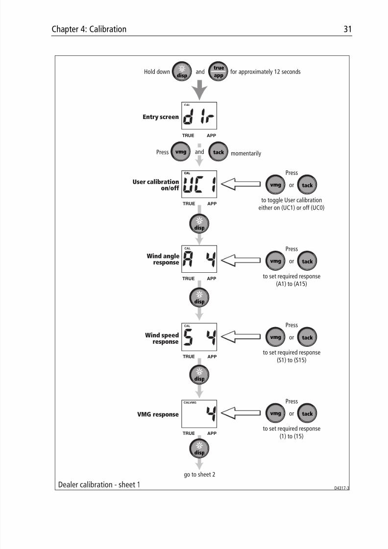
Dealer calibration also gives access to the Factory defaults screen. This enablesyou to re-apply the factory settings if you want to reset the instrument to a knownoperating condition.
To commence Dealer calibration, hold down the disp and true/app keystogether for approximately 12 seconds, to select the Dealer calibration entry page(see Dealer calibration diagram, sheets 1 and 2). Then momentarily press thevmgandtack keys to proceed with the calibration. As the calibration progresses,use the disp key to move from screen to screen.
User calibration on/offUse either the vmg or tack key to toggle the User calibration either on (UC1) oroff (UC0) as required.
Response settingsThe response values (for wind speed, wind angle and VMG) determine thefrequency at which information is updated. A low number provides a smoothresponse and a high number a much livelier response with rapid pointermovement.
Use the vmg (decrement) and tack (increment) keys to set the required value.
Response values are from 1 to 15 .
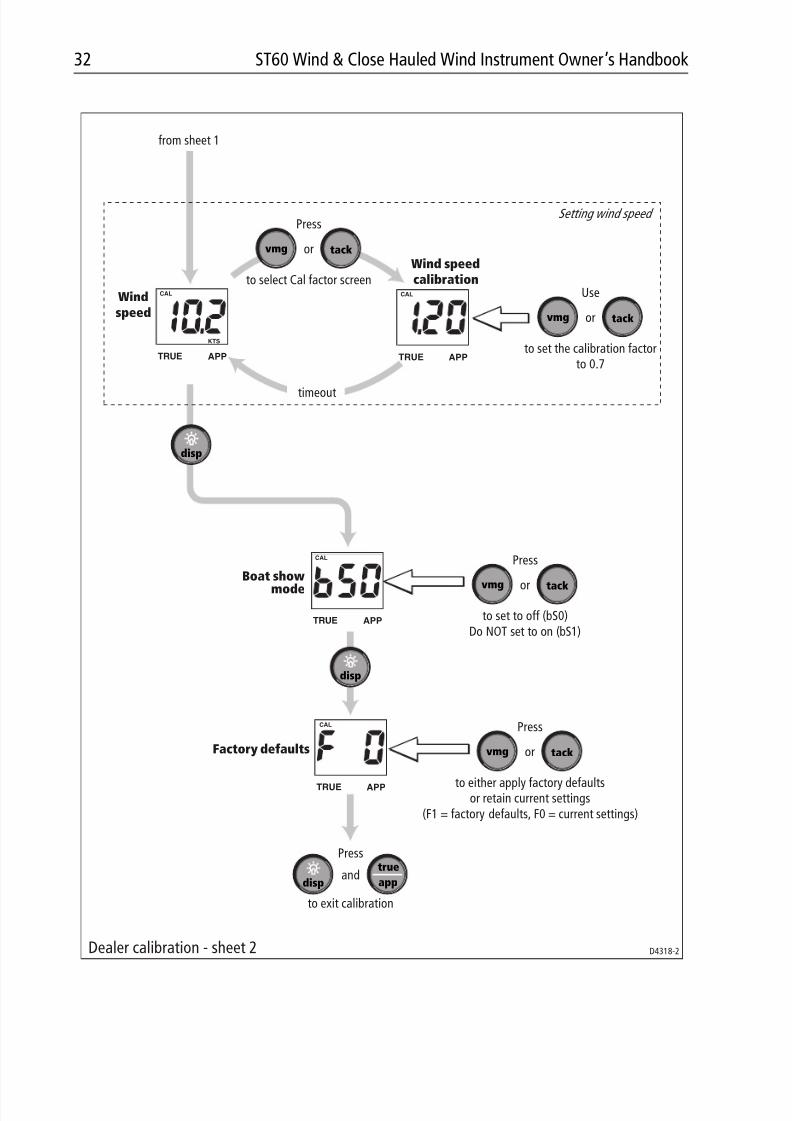
Wind speed
The Wind speed and Wind speed calibration screens are used to set the correctvalue for the wind speed. On entry (from the Wind speed response screen), thecurrent value for apparent wind speed is displayed. Set the correct wind speedvalue, by applying a calibration factor as follows:
1. Use the vmg (decrement) and tack (increment) keys to switch from the Wind
Speed screen to the Wind Speed Calibration screen.2. Use the vmg (decrement) or tack (increment) key to set the wind speed cali-
bration factor to 0.7.
3. Timeout to the Wind Speed screen, and if further adjustment is necessary,repeat steps 1 and 2.
8/3/2019 ST60 Wind Instrument Owner's Handbook
http://slidepdf.com/reader/full/st60-wind-instrument-owners-handbook 43/52
Chapter 4: Calibration 31
TRUE APP
Hold down and for approximately 12 secondsdisp
true
app
Dealer calibration - sheet 1
Entry screen
TRUE APP
TRUE APP
TRUE APP
vmg tackandPress momentarily
to toggle User calibrationeither on (UC1) or off (UC0)
vmgtackor
Press
to set required response
(A1) to (A15)
vmg tackor
Press
to set required response(S1) to (S15)
vmg tackor
Press
CALVMG
TRUE APP
disp
disp
disp
disp
go to sheet 2
User calibration
on/off
Wind angleresponse
Wind speedresponse
VMG response
to set required response(1) to (15)
vmg tackor
Press
D4317-3
CAL
CAL
CAL
CAL
CAL
8/3/2019 ST60 Wind Instrument Owner's Handbook
http://slidepdf.com/reader/full/st60-wind-instrument-owners-handbook 44/52
32 ST60 Wind & Close Hauled Wind Instrument Owner’s Handbook
anddisp
true
app
to either apply factory defaultsor retain current settings
(F1 = factory defaults, F0 = current settings)
vmg tackor
Press
from sheet 1
CAL
KTS
TRUE APP
CAL
TRUE APP
CAL
TRUE APP
TRUE APP
to set the calibration factorto 0.7
vmg tackor
Useto select Cal factor screen
vmg tackor
Press
timeout
Windspeed
Wind speedcalibration
Setting wind speed
disp
disp
to set to off (bS0)Do NOT set to on (bS1)
vmg tackor
Press
Press
to exit calibration
Boat showmode
Factory defaults
Dealer calibration - sheet 2 D4318-2
CAL
8/3/2019 ST60 Wind Instrument Owner's Handbook
http://slidepdf.com/reader/full/st60-wind-instrument-owners-handbook 45/52
Chapter 4: Calibration 33
Boat show mode
CAUTION:Do NOT enable this mode. It must only be used for demonstration
purposes.
Ensure that the Boatshow Mode Use is set to bS0 (disabled). If necessary, presseither the vmg key or the tack key to achieve this.
Factory defaultsYou can use this screen to reset the operating parameters to the factory defaultvalues. Use the vmg and tack keys to make the required selection.
Note that the selection you make at this screen will be applied when you exit thescreen, so be sure you make the correct selection.
If you want to apply the factory defaults, ensure the display shows F1 , but if youwant to retain the current values, ensure that the display shows F0 .
Leaving Dealer calibrationHold down the disp and true/app. keys for 2 seconds to save your changes, exitDealer calibration and resume normal operation.

8/3/2019 ST60 Wind Instrument Owner's Handbook
http://slidepdf.com/reader/full/st60-wind-instrument-owners-handbook 46/52
34 ST60 Wind & Close Hauled Wind Instrument Owner’s Handbook
8/3/2019 ST60 Wind Instrument Owner's Handbook
http://slidepdf.com/reader/full/st60-wind-instrument-owners-handbook 47/52
D4436-1
Machine hole90mm (3.54in)
diameter
Drill 5mm (3/16in) diameter
Drill 5mm (3/16in) diameter
Shaded areas to be removed
TOPST60 Surface Mount Template

8/3/2019 ST60 Wind Instrument Owner's Handbook
http://slidepdf.com/reader/full/st60-wind-instrument-owners-handbook 48/52
8/3/2019 ST60 Wind Instrument Owner's Handbook
http://slidepdf.com/reader/full/st60-wind-instrument-owners-handbook 49/52
Shaded area to be removed
TOP
109 mm
ST60 Flush Mount Template
1 1 4
m m
4 holes6 mm diameter
D4437-1

8/3/2019 ST60 Wind Instrument Owner's Handbook
http://slidepdf.com/reader/full/st60-wind-instrument-owners-handbook 50/52
8/3/2019 ST60 Wind Instrument Owner's Handbook
http://slidepdf.com/reader/full/st60-wind-instrument-owners-handbook 51/52
Front
50 mm
27.5 mm
34.5 mm
7 mm
10 mm
CenterLine
Drill hole, 4 mmdiameter
Drill hole, 4 mmdiameter
If cable is to leave base fromunderneath, drill hole, 8 mm diameter(not required if cable to exit from rear)
Wind vane drilling templateD6955-1
E d ge of wind vane ba s e

8/3/2019 ST60 Wind Instrument Owner's Handbook
http://slidepdf.com/reader/full/st60-wind-instrument-owners-handbook 52/52


![ST60+ Wind & Close Hauled Wind Instrumenten].pdfii ST60+ Wind & Close Hauled Wind Instrument Owner’s Handbook Product disposal Waste Electrical and Electronic (WEEE) Directive The](https://img.pdfslide.us/doc/110x75/5d41139f88c993f0558d4cd1/st60-wind-close-hauled-wind-instrument-enpdfii-st60-wind-close-hauled-wind.jpg)