Embed Size (px)
Citation preview
November 2018 UM2268 Rev 3 1/83
1
UM2268User manual
ST25RU3993-EVAL board software
Introduction
This document describes the graphical user interface (GUI) software (STSW-ST25RU001) for the ST25RU3993-EVAL board.
The ST25RU3993-EVAL board is a UHF RFID demonstration reader based on ST’s fully integrated Gen2 compatible reader ICs.
Additionally, a quick start guide includes a list of basic steps required to configure the demo reader for the most common applications.
www.st.com
Contents UM2268
2/83 UM2268 Rev 3
Contents
1 Quick start guide . . . . . . . . . . . . . . . . . . . . . . . . . . . . . . . . . . . . . . . . . . . . 7
1.1 Hardware preparations . . . . . . . . . . . . . . . . . . . . . . . . . . . . . . . . . . . . . . . . 7
1.2 Software installation . . . . . . . . . . . . . . . . . . . . . . . . . . . . . . . . . . . . . . . . . . 8
1.3 First connection . . . . . . . . . . . . . . . . . . . . . . . . . . . . . . . . . . . . . . . . . . . . . 9
2 GUI user guide . . . . . . . . . . . . . . . . . . . . . . . . . . . . . . . . . . . . . . . . . . . . . 12
2.1 Main Window . . . . . . . . . . . . . . . . . . . . . . . . . . . . . . . . . . . . . . . . . . . . . . 12
2.1.1 Main window menu . . . . . . . . . . . . . . . . . . . . . . . . . . . . . . . . . . . . . . . . 13
2.1.2 Main window controls . . . . . . . . . . . . . . . . . . . . . . . . . . . . . . . . . . . . . . 19
2.2 Reader settings - EU profile . . . . . . . . . . . . . . . . . . . . . . . . . . . . . . . . . . . 23
2.2.1 EU profile settings tab . . . . . . . . . . . . . . . . . . . . . . . . . . . . . . . . . . . . . . 23
2.2.2 Eu profile diagnostics tab . . . . . . . . . . . . . . . . . . . . . . . . . . . . . . . . . . . . 28
2.2.3 EU profile: Tuning tab . . . . . . . . . . . . . . . . . . . . . . . . . . . . . . . . . . . . . . 31
2.2.4 Reflected Power Radar . . . . . . . . . . . . . . . . . . . . . . . . . . . . . . . . . . . . . 33
2.3 Reader setting - USA profile . . . . . . . . . . . . . . . . . . . . . . . . . . . . . . . . . . . 35
2.3.1 USA profile settings tab . . . . . . . . . . . . . . . . . . . . . . . . . . . . . . . . . . . . . 35
2.3.2 USA profile diagnostics tab . . . . . . . . . . . . . . . . . . . . . . . . . . . . . . . . . . 40
2.3.3 USA profile tuning tab . . . . . . . . . . . . . . . . . . . . . . . . . . . . . . . . . . . . . . 42
2.3.4 USA profile reflected Power Radar . . . . . . . . . . . . . . . . . . . . . . . . . . . . 44
2.4 Reader settings - JAPAN profile . . . . . . . . . . . . . . . . . . . . . . . . . . . . . . . . 46
2.4.1 JAPAN profile settings tab . . . . . . . . . . . . . . . . . . . . . . . . . . . . . . . . . . . 46
2.4.2 JAPAN profile diagnostics tab . . . . . . . . . . . . . . . . . . . . . . . . . . . . . . . . 51
2.4.3 JAPAN profile Tuning tab . . . . . . . . . . . . . . . . . . . . . . . . . . . . . . . . . . . . 54
2.4.4 JAPAN profile reflected Power Radar . . . . . . . . . . . . . . . . . . . . . . . . . . 56
2.5 Eval mode . . . . . . . . . . . . . . . . . . . . . . . . . . . . . . . . . . . . . . . . . . . . . . . . 58
2.5.1 Eval mode settings tab . . . . . . . . . . . . . . . . . . . . . . . . . . . . . . . . . . . . . 58
2.5.2 Eval mode diagnostics tab . . . . . . . . . . . . . . . . . . . . . . . . . . . . . . . . . . . 63
2.5.3 Eval mode tuning tab . . . . . . . . . . . . . . . . . . . . . . . . . . . . . . . . . . . . . . . 66
2.5.4 Eval mode Reflected Power Radar . . . . . . . . . . . . . . . . . . . . . . . . . . . . 68
2.6 Register map . . . . . . . . . . . . . . . . . . . . . . . . . . . . . . . . . . . . . . . . . . . . . . 70
2.6.1 Register map - File menu . . . . . . . . . . . . . . . . . . . . . . . . . . . . . . . . . . . 71
2.6.2 Register map - View menu . . . . . . . . . . . . . . . . . . . . . . . . . . . . . . . . . . 72
2.7 Tag Associations . . . . . . . . . . . . . . . . . . . . . . . . . . . . . . . . . . . . . . . . . . . 73
UM2268 Rev 3 3/83
UM2268 Contents
3
2.8 Tag Settings . . . . . . . . . . . . . . . . . . . . . . . . . . . . . . . . . . . . . . . . . . . . . . . 75
2.8.1 Information panel . . . . . . . . . . . . . . . . . . . . . . . . . . . . . . . . . . . . . . . . . . 76
2.8.2 Functions panel . . . . . . . . . . . . . . . . . . . . . . . . . . . . . . . . . . . . . . . . . . . 76
3 Revision history . . . . . . . . . . . . . . . . . . . . . . . . . . . . . . . . . . . . . . . . . . . 82
List of figures UM2268
4/83 UM2268 Rev 3
List of figures
Figure 1. Hardware configuration of evaluation board . . . . . . . . . . . . . . . . . . . . . . . . . . . . . . . . . . . . . 7Figure 2. ST25RU3993 GUI software installation wizard steps . . . . . . . . . . . . . . . . . . . . . . . . . . . . . . 8Figure 3. Message screen shot . . . . . . . . . . . . . . . . . . . . . . . . . . . . . . . . . . . . . . . . . . . . . . . . . . . . . . 9Figure 4. ST25RU3993 GUI icon . . . . . . . . . . . . . . . . . . . . . . . . . . . . . . . . . . . . . . . . . . . . . . . . . . . . . 9Figure 5. GUI control menu . . . . . . . . . . . . . . . . . . . . . . . . . . . . . . . . . . . . . . . . . . . . . . . . . . . . . . . . 10Figure 6. Board detected after initial connection . . . . . . . . . . . . . . . . . . . . . . . . . . . . . . . . . . . . . . . . 10Figure 7. USB serial port listed in Windows® Device Manager . . . . . . . . . . . . . . . . . . . . . . . . . . . . . 11Figure 8. ST25RU3993 GUI main window. . . . . . . . . . . . . . . . . . . . . . . . . . . . . . . . . . . . . . . . . . . . . 12Figure 9. Control menu window . . . . . . . . . . . . . . . . . . . . . . . . . . . . . . . . . . . . . . . . . . . . . . . . . . . . . 13Figure 10. View menu window . . . . . . . . . . . . . . . . . . . . . . . . . . . . . . . . . . . . . . . . . . . . . . . . . . . . . . . 14Figure 11. Tag list window . . . . . . . . . . . . . . . . . . . . . . . . . . . . . . . . . . . . . . . . . . . . . . . . . . . . . . . . . . 15Figure 12. Global Action window . . . . . . . . . . . . . . . . . . . . . . . . . . . . . . . . . . . . . . . . . . . . . . . . . . . . . 16Figure 13. ST25RU3993 GUI Settings window . . . . . . . . . . . . . . . . . . . . . . . . . . . . . . . . . . . . . . . . . . 17Figure 14. Help menu . . . . . . . . . . . . . . . . . . . . . . . . . . . . . . . . . . . . . . . . . . . . . . . . . . . . . . . . . . . . . 18Figure 15. Firmware update progress window. . . . . . . . . . . . . . . . . . . . . . . . . . . . . . . . . . . . . . . . . . . 18Figure 16. Main window - Reader Settings . . . . . . . . . . . . . . . . . . . . . . . . . . . . . . . . . . . . . . . . . . . . . 19Figure 17. Pop up menu - Reader entry . . . . . . . . . . . . . . . . . . . . . . . . . . . . . . . . . . . . . . . . . . . . . . . 19Figure 18. Tag information panel in main window . . . . . . . . . . . . . . . . . . . . . . . . . . . . . . . . . . . . . . . . 20Figure 19. Pop up menu - Tag Entry . . . . . . . . . . . . . . . . . . . . . . . . . . . . . . . . . . . . . . . . . . . . . . . . . . 20Figure 20. Side bar - Read information . . . . . . . . . . . . . . . . . . . . . . . . . . . . . . . . . . . . . . . . . . . . . . . . 21Figure 21. Main window - Start scanning for Tags. . . . . . . . . . . . . . . . . . . . . . . . . . . . . . . . . . . . . . . . 21Figure 22. Main window - Select . . . . . . . . . . . . . . . . . . . . . . . . . . . . . . . . . . . . . . . . . . . . . . . . . . . . . 22Figure 23. Main window - Control . . . . . . . . . . . . . . . . . . . . . . . . . . . . . . . . . . . . . . . . . . . . . . . . . . . . 22Figure 24. EU profile reader Settings window: General tab. . . . . . . . . . . . . . . . . . . . . . . . . . . . . . . . . 23Figure 25. EU profile session selection . . . . . . . . . . . . . . . . . . . . . . . . . . . . . . . . . . . . . . . . . . . . . . . . 26Figure 26. Reader Settings window: Diagnostics tab . . . . . . . . . . . . . . . . . . . . . . . . . . . . . . . . . . . . . 28Figure 27. EU profile Reflect Power window . . . . . . . . . . . . . . . . . . . . . . . . . . . . . . . . . . . . . . . . . . . . 29Figure 28. EU profile Reader Setting window: Tuning tab . . . . . . . . . . . . . . . . . . . . . . . . . . . . . . . . . . 31Figure 29. EU profile tuning file structure. . . . . . . . . . . . . . . . . . . . . . . . . . . . . . . . . . . . . . . . . . . . . . . 32Figure 30. EU profile tuning file example . . . . . . . . . . . . . . . . . . . . . . . . . . . . . . . . . . . . . . . . . . . . . . . 32Figure 31. EU profile reflected power radar . . . . . . . . . . . . . . . . . . . . . . . . . . . . . . . . . . . . . . . . . . . . . 33Figure 32. USA profile reader Settings window: General tab . . . . . . . . . . . . . . . . . . . . . . . . . . . . . . . 35Figure 33. USA profile session selection . . . . . . . . . . . . . . . . . . . . . . . . . . . . . . . . . . . . . . . . . . . . . . . 38Figure 34. USA profile Reader Settings window: Diagnostics tab . . . . . . . . . . . . . . . . . . . . . . . . . . . . 40Figure 35. Reflect Power window . . . . . . . . . . . . . . . . . . . . . . . . . . . . . . . . . . . . . . . . . . . . . . . . . . . . 41Figure 36. USA profile Reader Setting window: Tuning tab. . . . . . . . . . . . . . . . . . . . . . . . . . . . . . . . . 42Figure 37. Tuning file structure . . . . . . . . . . . . . . . . . . . . . . . . . . . . . . . . . . . . . . . . . . . . . . . . . . . . . . 43Figure 38. Tuning file example. . . . . . . . . . . . . . . . . . . . . . . . . . . . . . . . . . . . . . . . . . . . . . . . . . . . . . . 43Figure 39. EU profile reflected power radar . . . . . . . . . . . . . . . . . . . . . . . . . . . . . . . . . . . . . . . . . . . . . 44Figure 40. JAPAN profile Reader Settings window: General tab . . . . . . . . . . . . . . . . . . . . . . . . . . . . . 46Figure 41. JAPAN profile session selection . . . . . . . . . . . . . . . . . . . . . . . . . . . . . . . . . . . . . . . . . . . . . 49Figure 42. JAPAN profile Reader Settings window: Diagnostics tab . . . . . . . . . . . . . . . . . . . . . . . . . . 51Figure 43. JAPAN profile Reflect Power window . . . . . . . . . . . . . . . . . . . . . . . . . . . . . . . . . . . . . . . . . 52Figure 44. Japan profile Reader Setting window: Tuning tab . . . . . . . . . . . . . . . . . . . . . . . . . . . . . . . 54Figure 45. Tuning file structure . . . . . . . . . . . . . . . . . . . . . . . . . . . . . . . . . . . . . . . . . . . . . . . . . . . . . . 55Figure 46. Tuning file example. . . . . . . . . . . . . . . . . . . . . . . . . . . . . . . . . . . . . . . . . . . . . . . . . . . . . . . 55Figure 47. JAPAN profile Reflected Power Radar . . . . . . . . . . . . . . . . . . . . . . . . . . . . . . . . . . . . . . . . 56Figure 48. Eval mode Reader Settings window: General tab . . . . . . . . . . . . . . . . . . . . . . . . . . . . . . . 58
UM2268 Rev 3 5/83
UM2268 List of figures
5
Figure 49. Eval mode Session selection . . . . . . . . . . . . . . . . . . . . . . . . . . . . . . . . . . . . . . . . . . . . . . . 61Figure 50. Eval mode Reader Settings window: Diagnostics tab . . . . . . . . . . . . . . . . . . . . . . . . . . . . 63Figure 51. Eval mode Reflect Power window . . . . . . . . . . . . . . . . . . . . . . . . . . . . . . . . . . . . . . . . . . . 64Figure 52. Eval mode Reader setting window: Tuning tab . . . . . . . . . . . . . . . . . . . . . . . . . . . . . . . . . 66Figure 53. Tuning file structure . . . . . . . . . . . . . . . . . . . . . . . . . . . . . . . . . . . . . . . . . . . . . . . . . . . . . . 67Figure 54. Tuning file example. . . . . . . . . . . . . . . . . . . . . . . . . . . . . . . . . . . . . . . . . . . . . . . . . . . . . . . 67Figure 55. Reflected power radar . . . . . . . . . . . . . . . . . . . . . . . . . . . . . . . . . . . . . . . . . . . . . . . . . . . . 68Figure 56. Register map window . . . . . . . . . . . . . . . . . . . . . . . . . . . . . . . . . . . . . . . . . . . . . . . . . . . . . 71Figure 57. Tag association window . . . . . . . . . . . . . . . . . . . . . . . . . . . . . . . . . . . . . . . . . . . . . . . . . . . 73Figure 58. Tag Setting window . . . . . . . . . . . . . . . . . . . . . . . . . . . . . . . . . . . . . . . . . . . . . . . . . . . . . . 75Figure 59. Reading and setting tag memory banks . . . . . . . . . . . . . . . . . . . . . . . . . . . . . . . . . . . . . . . 77Figure 60. Set EPC . . . . . . . . . . . . . . . . . . . . . . . . . . . . . . . . . . . . . . . . . . . . . . . . . . . . . . . . . . . . . . . 78Figure 61. Set password . . . . . . . . . . . . . . . . . . . . . . . . . . . . . . . . . . . . . . . . . . . . . . . . . . . . . . . . . . . 79Figure 62. Lock and unlock Tag Memory. . . . . . . . . . . . . . . . . . . . . . . . . . . . . . . . . . . . . . . . . . . . . . . 80Figure 63. Killing a tag . . . . . . . . . . . . . . . . . . . . . . . . . . . . . . . . . . . . . . . . . . . . . . . . . . . . . . . . . . . . . 81

List of tables UM2268
6/83 UM2268 Rev 3
List of tables
Table 1. Copy Registers to Clipboard - Example 1. . . . . . . . . . . . . . . . . . . . . . . . . . . . . . . . . . . . . . 72Table 2. Copy Registers to Clipboard - Example 2. . . . . . . . . . . . . . . . . . . . . . . . . . . . . . . . . . . . . . 72Table 3. Document revision history . . . . . . . . . . . . . . . . . . . . . . . . . . . . . . . . . . . . . . . . . . . . . . . . . 82
UM2268 Rev 3 7/83
UM2268 Quick start guide
81
1 Quick start guide
1.1 Hardware preparations
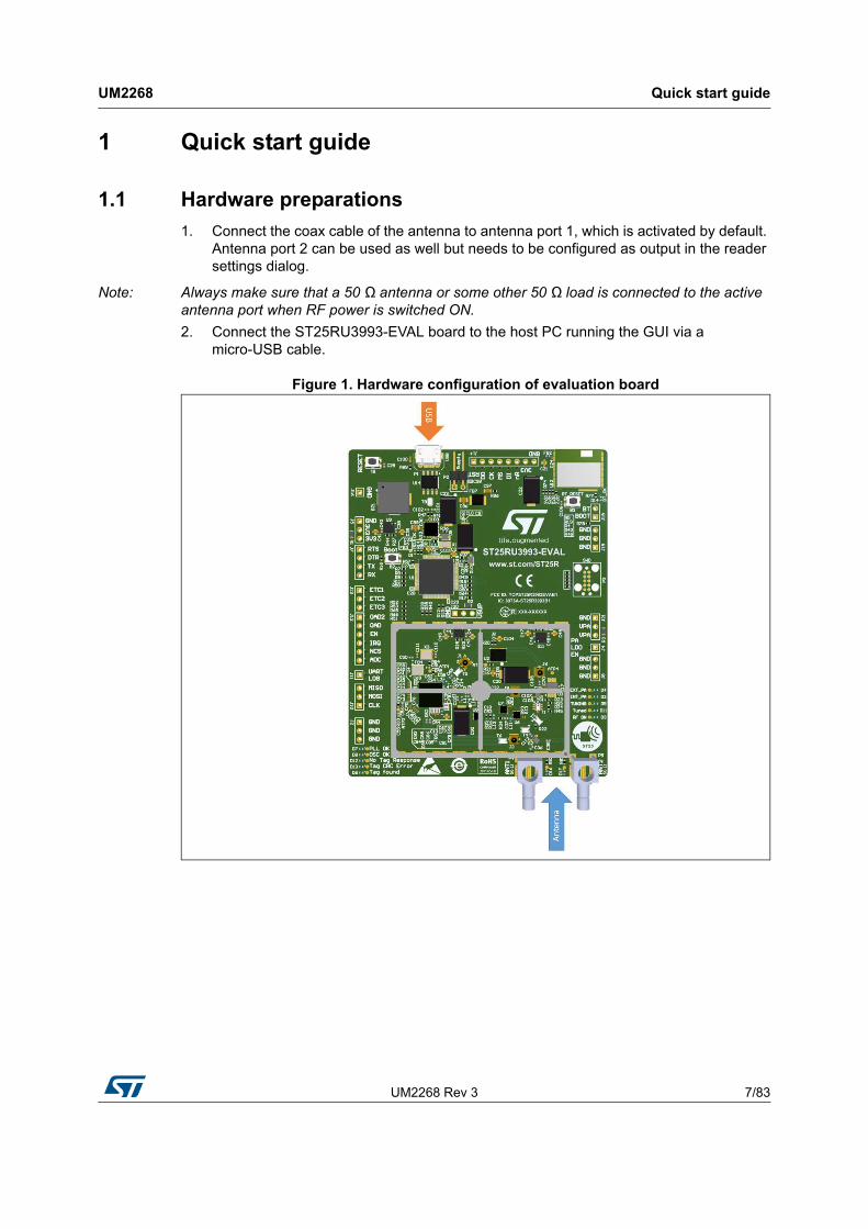
1. Connect the coax cable of the antenna to antenna port 1, which is activated by default. Antenna port 2 can be used as well but needs to be configured as output in the reader settings dialog.
Note: Always make sure that a 50 Ω antenna or some other 50 Ω load is connected to the active antenna port when RF power is switched ON.
2. Connect the ST25RU3993-EVAL board to the host PC running the GUI via a micro-USB cable.
Figure 1. Hardware configuration of evaluation board
Quick start guide UM2268
8/83 UM2268 Rev 3
1.2 Software installation
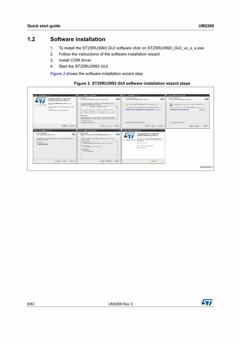
1. To install the ST25RU3993 GUI software click on ST25RU3993_GUI_vx_x_x.exe
2. Follow the instructions of the software installation wizard
3. Install COM driver
4. Start the ST25RU3993 GUI
Figure 2 shows the software installation wizard step
Figure 2. ST25RU3993 GUI software installation wizard steps
UM2268 Rev 3 9/83
UM2268 Quick start guide
81
1.3 First connection
1. In case GUI is not already running, start the ST25RU3993 GUI through the desktop symbol shown in Figure 4
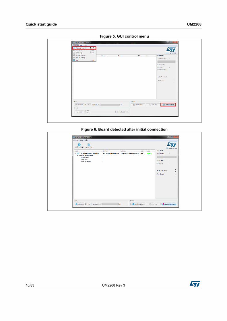
2. Click on the Connect Reader button, or go to the menu Control and select Connect Reader. Alternatively you can also press Ctrl+A (Figure 5).
3. The application automatically scans all available COM ports for a connected ST25RU3993-Eval board.
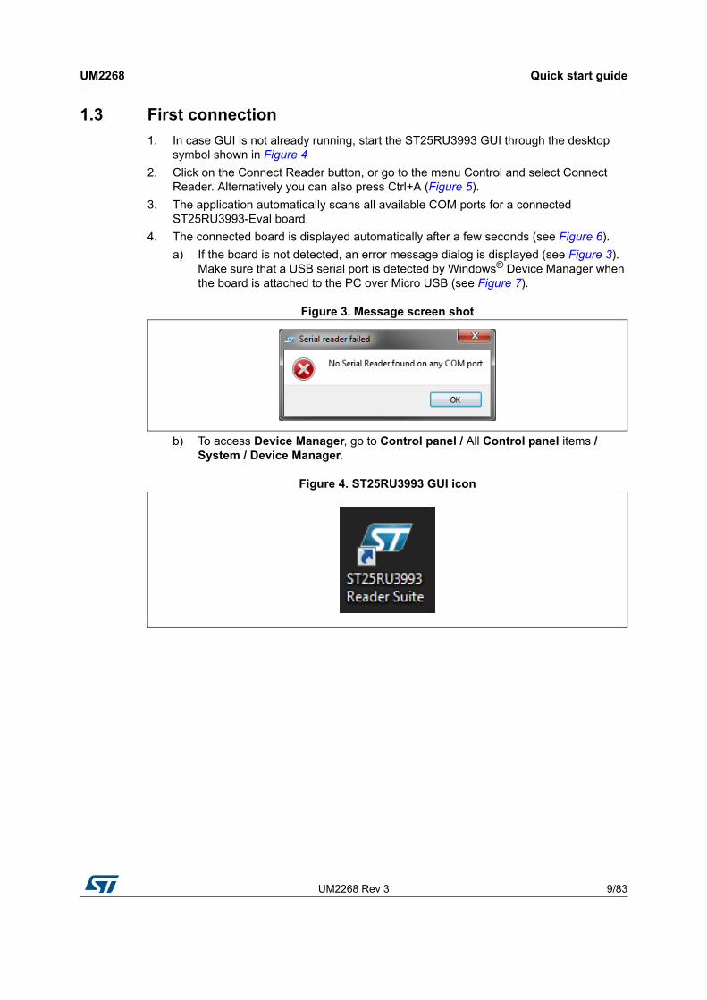
4. The connected board is displayed automatically after a few seconds (see Figure 6).
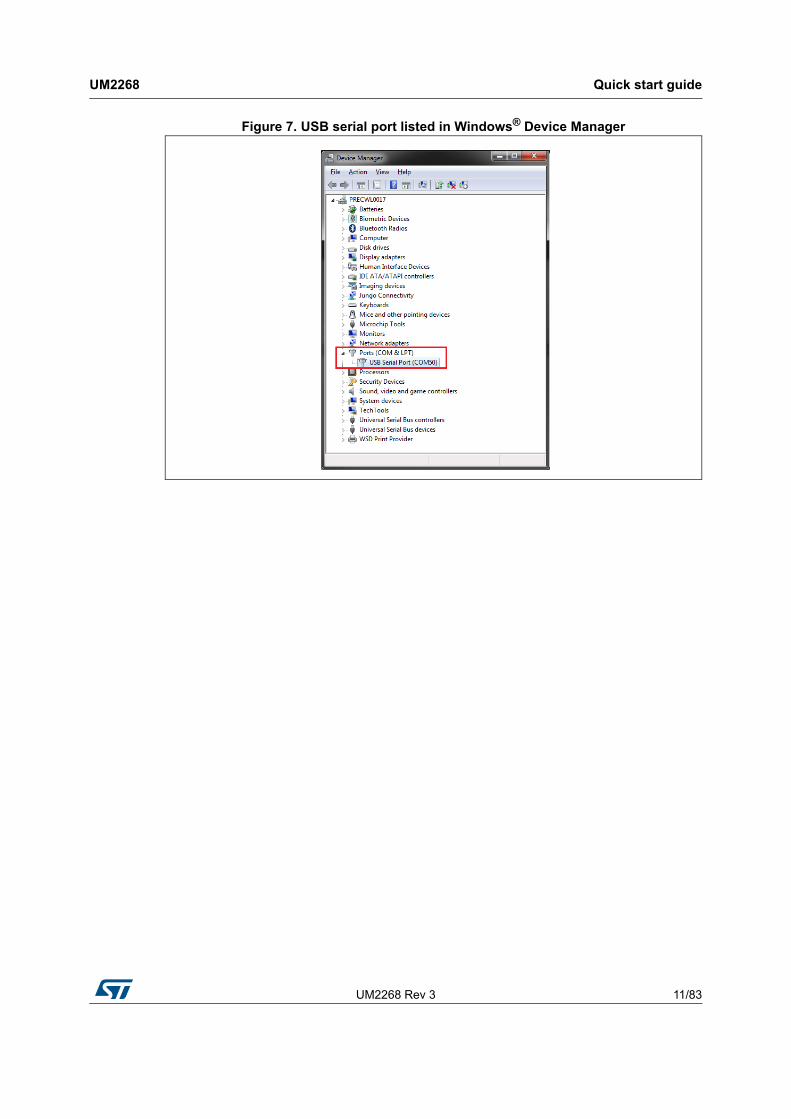
a) If the board is not detected, an error message dialog is displayed (see Figure 3). Make sure that a USB serial port is detected by Windows® Device Manager when the board is attached to the PC over Micro USB (see Figure 7).
Figure 3. Message screen shot
b) To access Device Manager, go to Control panel / All Control panel items / System / Device Manager.
Figure 4. ST25RU3993 GUI icon
Quick start guide UM2268
10/83 UM2268 Rev 3
Figure 5. GUI control menu
Figure 6. Board detected after initial connection
UM2268 Rev 3 11/83
UM2268 Quick start guide
81
Figure 7. USB serial port listed in Windows® Device Manager
GUI user guide UM2268
12/83 UM2268 Rev 3
2 GUI user guide
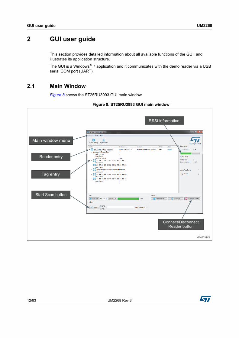
This section provides detailed information about all available functions of the GUI, and illustrates its application structure.
The GUI is a Windows® 7 application and it communicates with the demo reader via a USB serial COM port (UART).
2.1 Main Window
Figure 8 shows the ST25RU3993 GUI main window
Figure 8. ST25RU3993 GUI main window
UM2268 Rev 3 13/83
UM2268 GUI user guide
81
2.1.1 Main window menu
Control menu
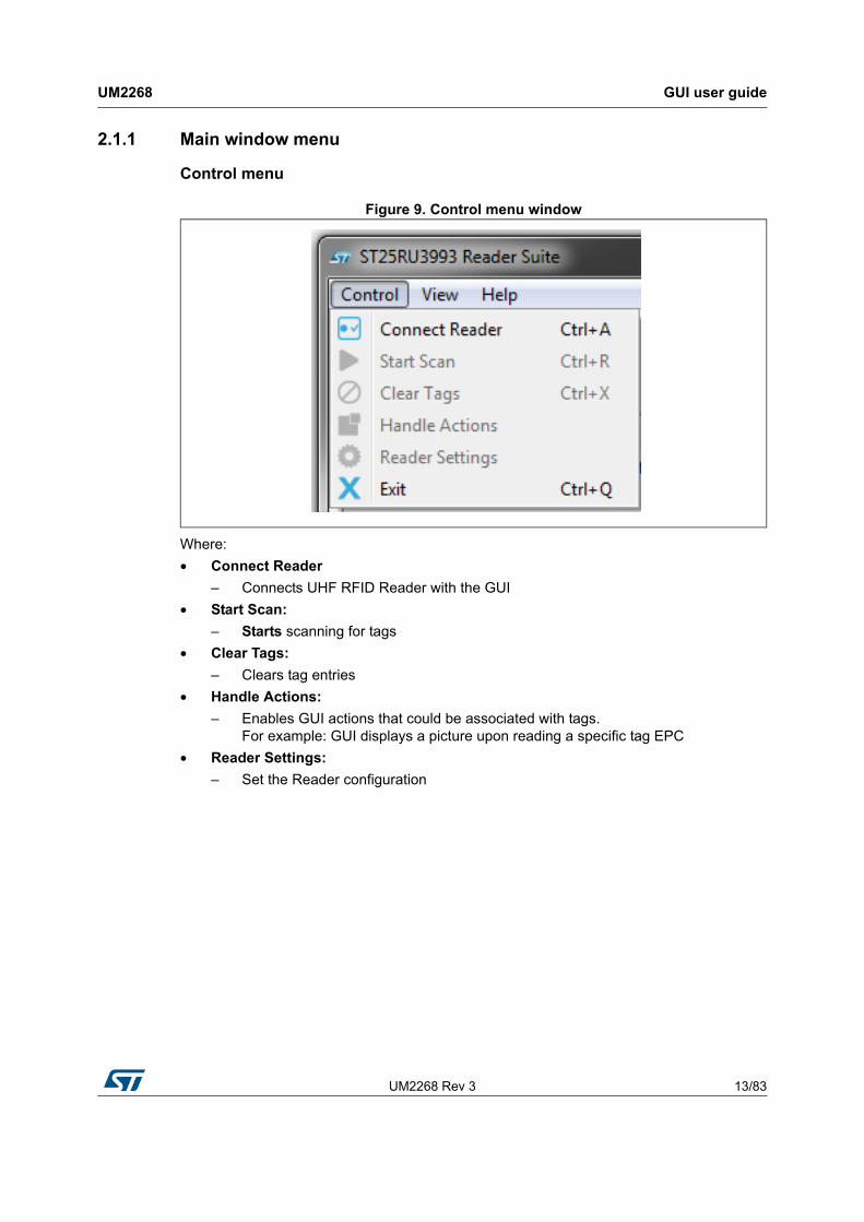
Figure 9. Control menu window
Where:
• Connect Reader
– Connects UHF RFID Reader with the GUI
• Start Scan:
– Starts scanning for tags
• Clear Tags:
– Clears tag entries
• Handle Actions:
– Enables GUI actions that could be associated with tags. For example: GUI displays a picture upon reading a specific tag EPC
• Reader Settings:
– Set the Reader configuration
GUI user guide UM2268
14/83 UM2268 Rev 3
View menu
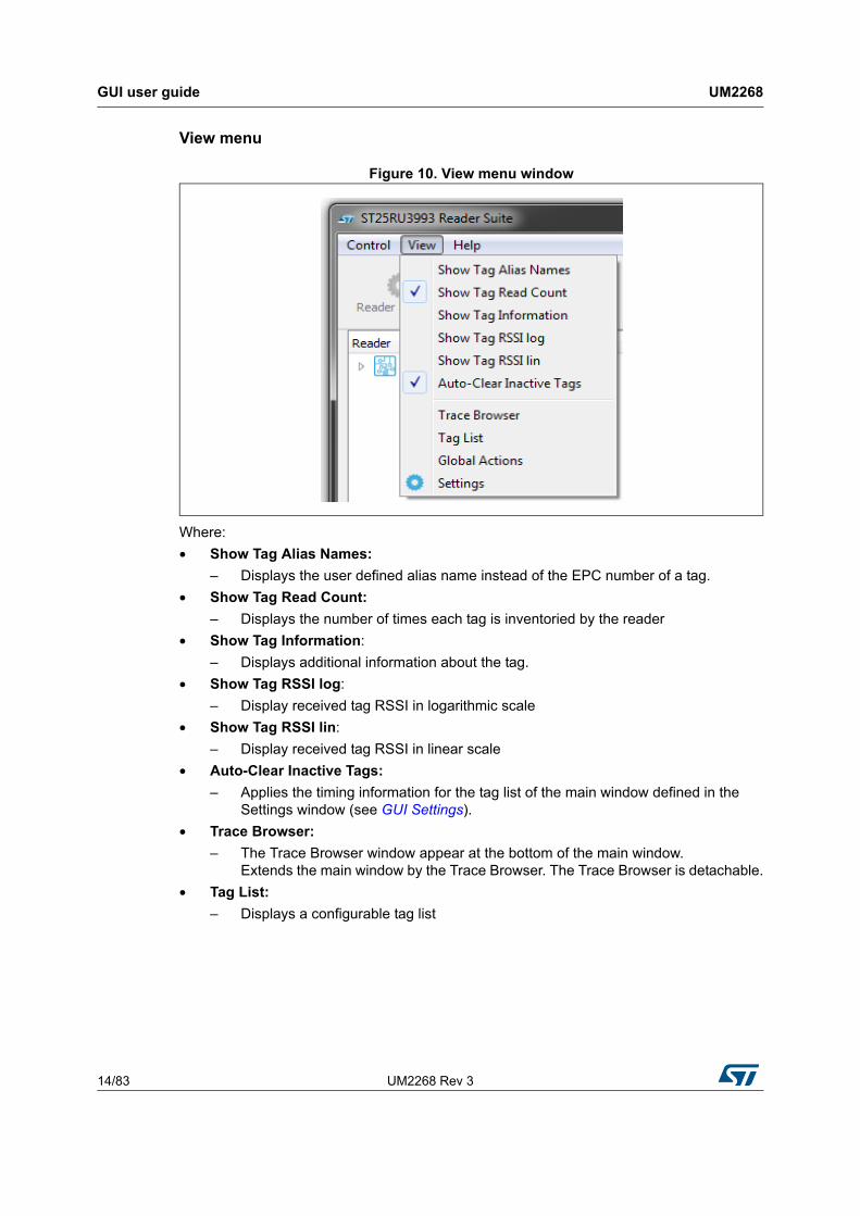
Figure 10. View menu window
Where:
• Show Tag Alias Names:
– Displays the user defined alias name instead of the EPC number of a tag.
• Show Tag Read Count:
– Displays the number of times each tag is inventoried by the reader
• Show Tag Information:
– Displays additional information about the tag.
• Show Tag RSSI log:
– Display received tag RSSI in logarithmic scale
• Show Tag RSSI lin:
– Display received tag RSSI in linear scale
• Auto-Clear Inactive Tags:
– Applies the timing information for the tag list of the main window defined in the Settings window (see GUI Settings).
• Trace Browser:
– The Trace Browser window appear at the bottom of the main window. Extends the main window by the Trace Browser. The Trace Browser is detachable.
• Tag List:
– Displays a configurable tag list
UM2268 Rev 3 15/83
UM2268 GUI user guide
81
Tag List
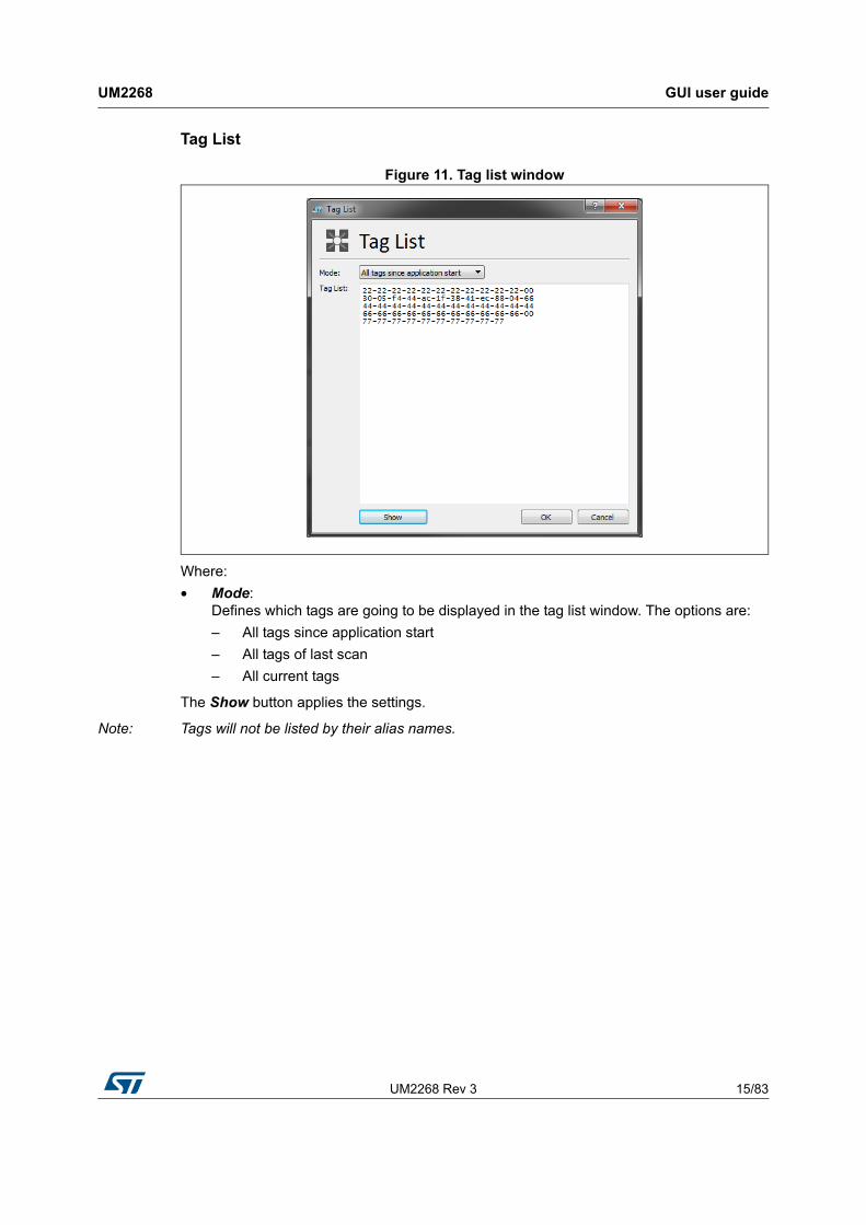
Figure 11. Tag list window
Where:
• Mode: Defines which tags are going to be displayed in the tag list window. The options are:
– All tags since application start
– All tags of last scan
– All current tags
The Show button applies the settings.
Note: Tags will not be listed by their alias names.
GUI user guide UM2268
16/83 UM2268 Rev 3
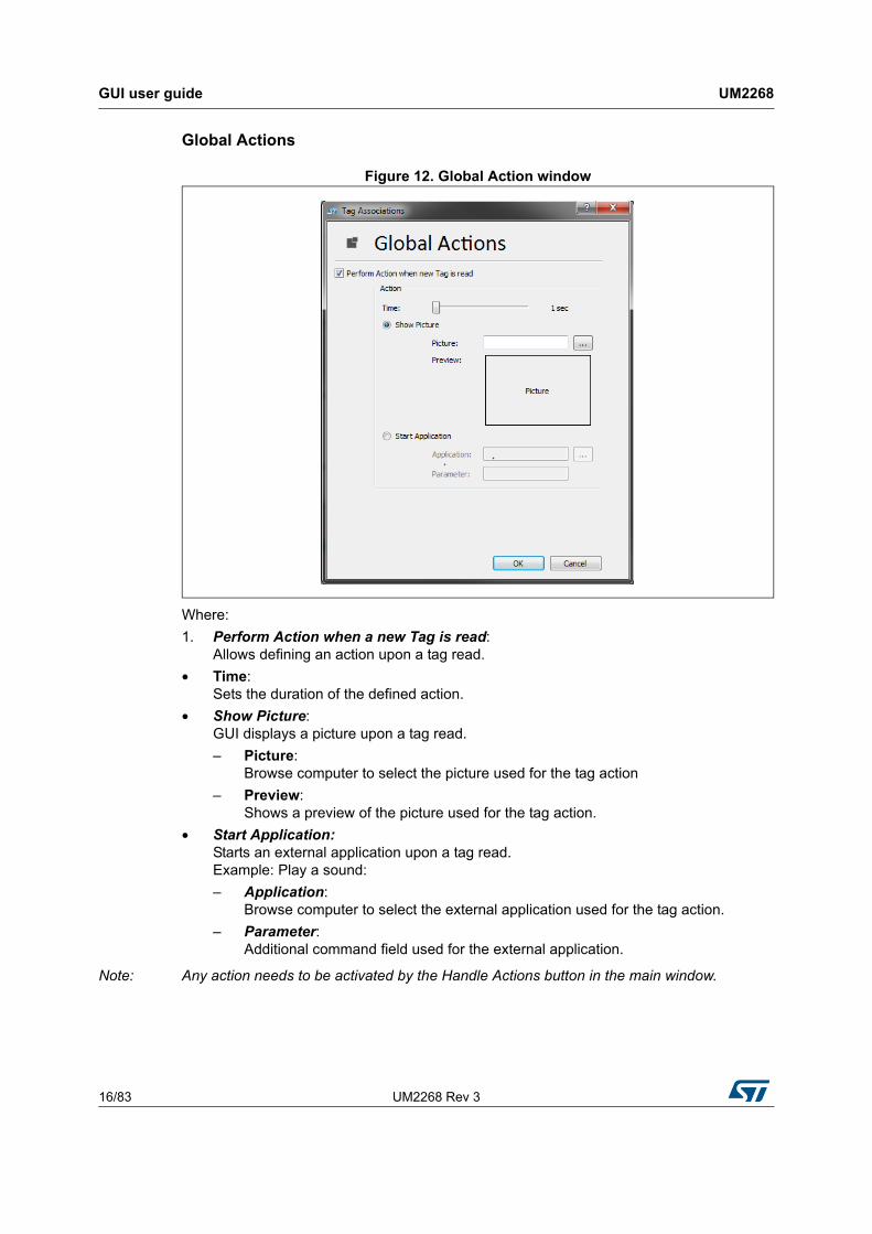
Global Actions
Figure 12. Global Action window
Where:
1. Perform Action when a new Tag is read: Allows defining an action upon a tag read.
• Time: Sets the duration of the defined action.
• Show Picture: GUI displays a picture upon a tag read.
– Picture: Browse computer to select the picture used for the tag action
– Preview: Shows a preview of the picture used for the tag action.
• Start Application: Starts an external application upon a tag read. Example: Play a sound:
– Application: Browse computer to select the external application used for the tag action.
– Parameter: Additional command field used for the external application.
Note: Any action needs to be activated by the Handle Actions button in the main window.
UM2268 Rev 3 17/83
UM2268 GUI user guide
81
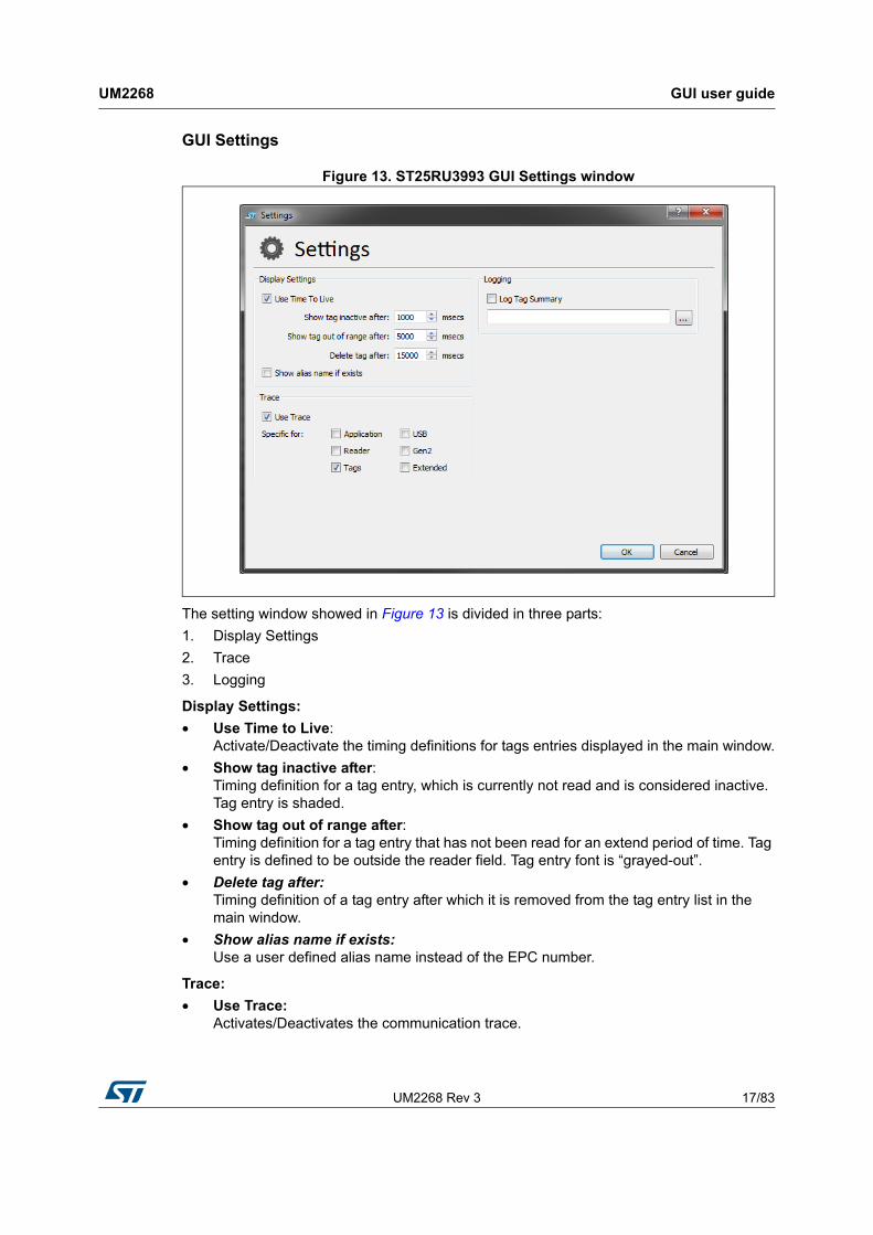
GUI Settings
Figure 13. ST25RU3993 GUI Settings window
The setting window showed in Figure 13 is divided in three parts:
1. Display Settings
2. Trace
3. Logging
Display Settings:
• Use Time to Live: Activate/Deactivate the timing definitions for tags entries displayed in the main window.
• Show tag inactive after: Timing definition for a tag entry, which is currently not read and is considered inactive. Tag entry is shaded.
• Show tag out of range after: Timing definition for a tag entry that has not been read for an extend period of time. Tag entry is defined to be outside the reader field. Tag entry font is “grayed-out”.
• Delete tag after: Timing definition of a tag entry after which it is removed from the tag entry list in the main window.
• Show alias name if exists: Use a user defined alias name instead of the EPC number.
Trace:
• Use Trace: Activates/Deactivates the communication trace.
GUI user guide UM2268
18/83 UM2268 Rev 3
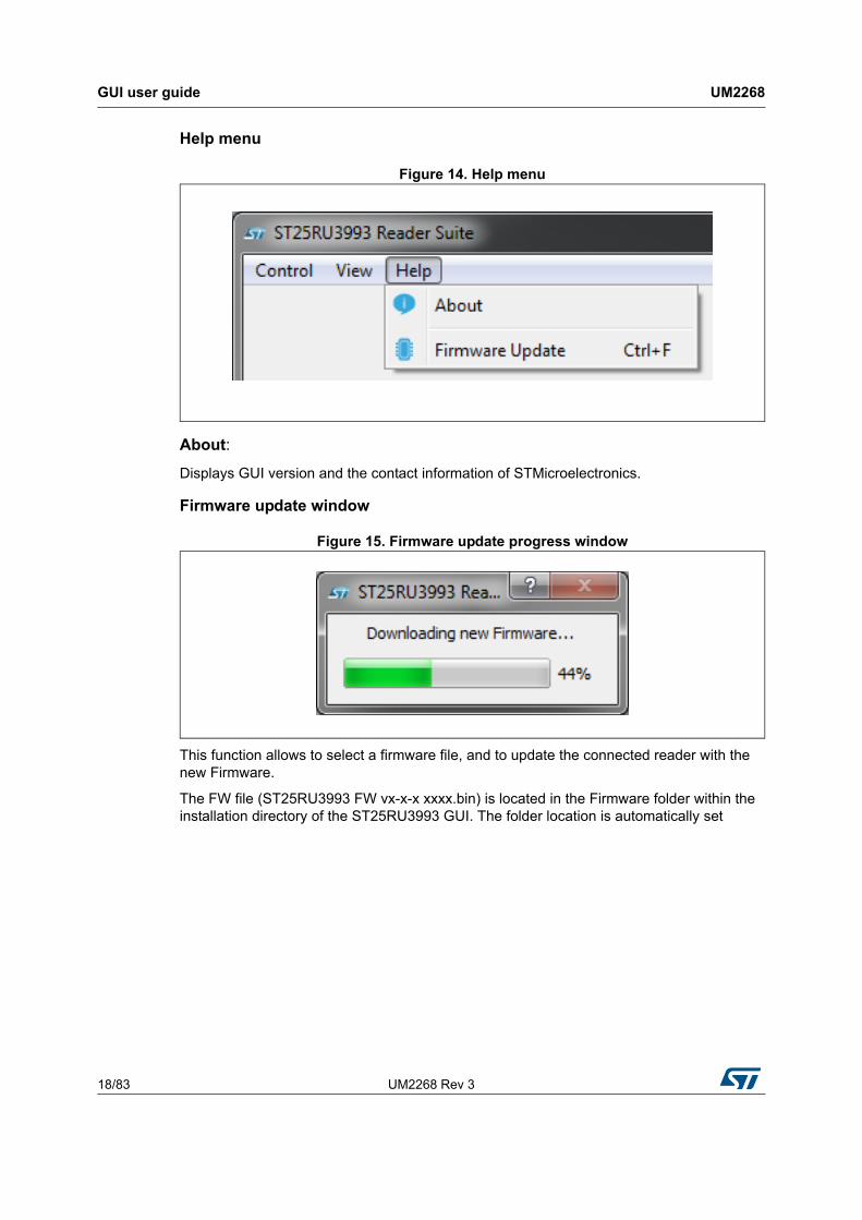
Help menu
Figure 14. Help menu
About:
Displays GUI version and the contact information of STMicroelectronics.
Firmware update window
Figure 15. Firmware update progress window
This function allows to select a firmware file, and to update the connected reader with the new Firmware.
The FW file (ST25RU3993 FW vx-x-x xxxx.bin) is located in the Firmware folder within the installation directory of the ST25RU3993 GUI. The folder location is automatically set
UM2268 Rev 3 19/83
UM2268 GUI user guide
81
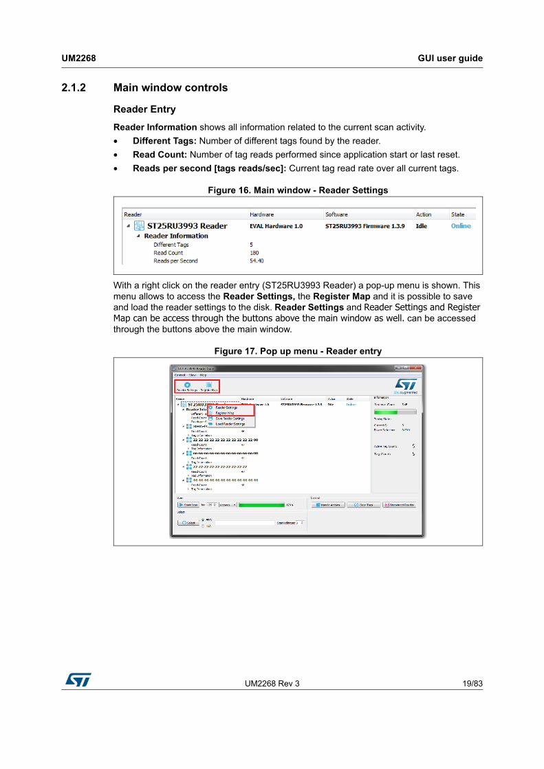
2.1.2 Main window controls
Reader Entry
Reader Information shows all information related to the current scan activity.
• Different Tags: Number of different tags found by the reader.
• Read Count: Number of tag reads performed since application start or last reset.
• Reads per second [tags reads/sec]: Current tag read rate over all current tags.
Figure 16. Main window - Reader Settings
With a right click on the reader entry (ST25RU3993 Reader) a pop-up menu is shown. This menu allows to access the Reader Settings, the Register Map and it is possible to save and load the reader settings to the disk. Reader Settings and Reader Settings and Register Map can be access through the buttons above the main window as well. can be accessed through the buttons above the main window.
Figure 17. Pop up menu - Reader entry
GUI user guide UM2268
20/83 UM2268 Rev 3
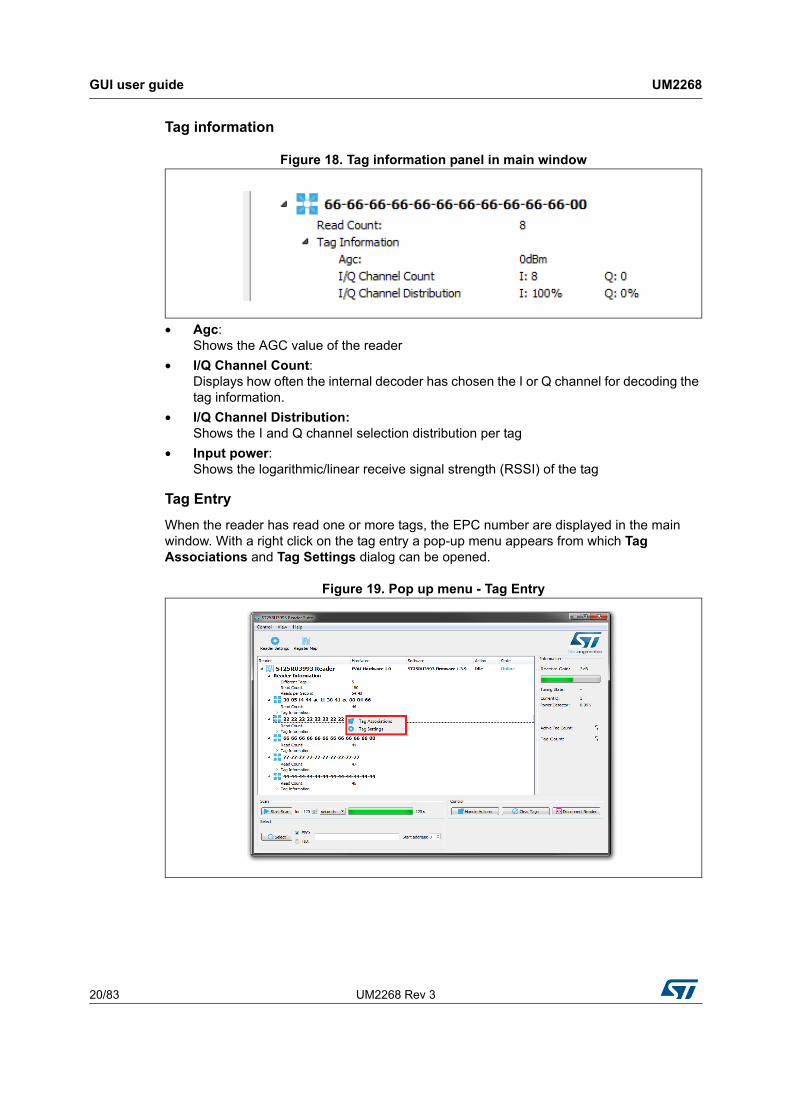
Tag information
Figure 18. Tag information panel in main window
• Agc: Shows the AGC value of the reader
• I/Q Channel Count: Displays how often the internal decoder has chosen the I or Q channel for decoding the tag information.
• I/Q Channel Distribution: Shows the I and Q channel selection distribution per tag
• Input power: Shows the logarithmic/linear receive signal strength (RSSI) of the tag
Tag Entry
When the reader has read one or more tags, the EPC number are displayed in the main window. With a right click on the tag entry a pop-up menu appears from which Tag Associations and Tag Settings dialog can be opened.
Figure 19. Pop up menu - Tag Entry
UM2268 Rev 3 21/83
UM2268 GUI user guide
81
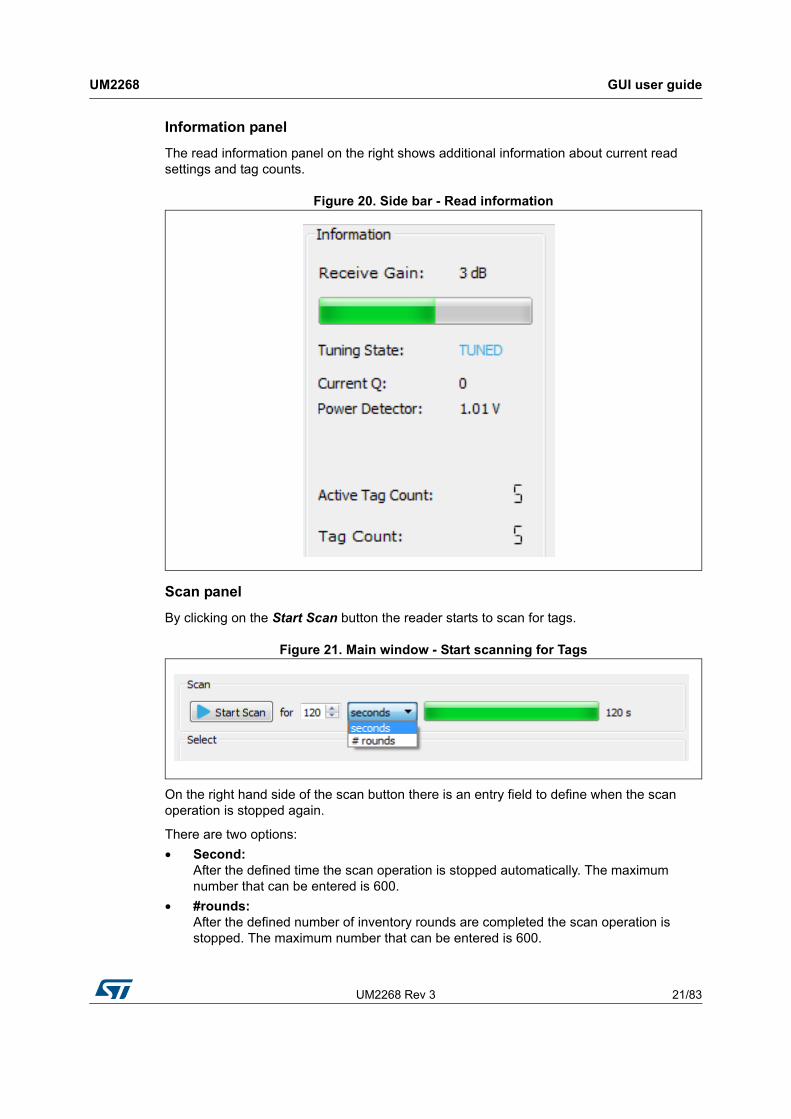
Information panel
The read information panel on the right shows additional information about current read settings and tag counts.
Figure 20. Side bar - Read information
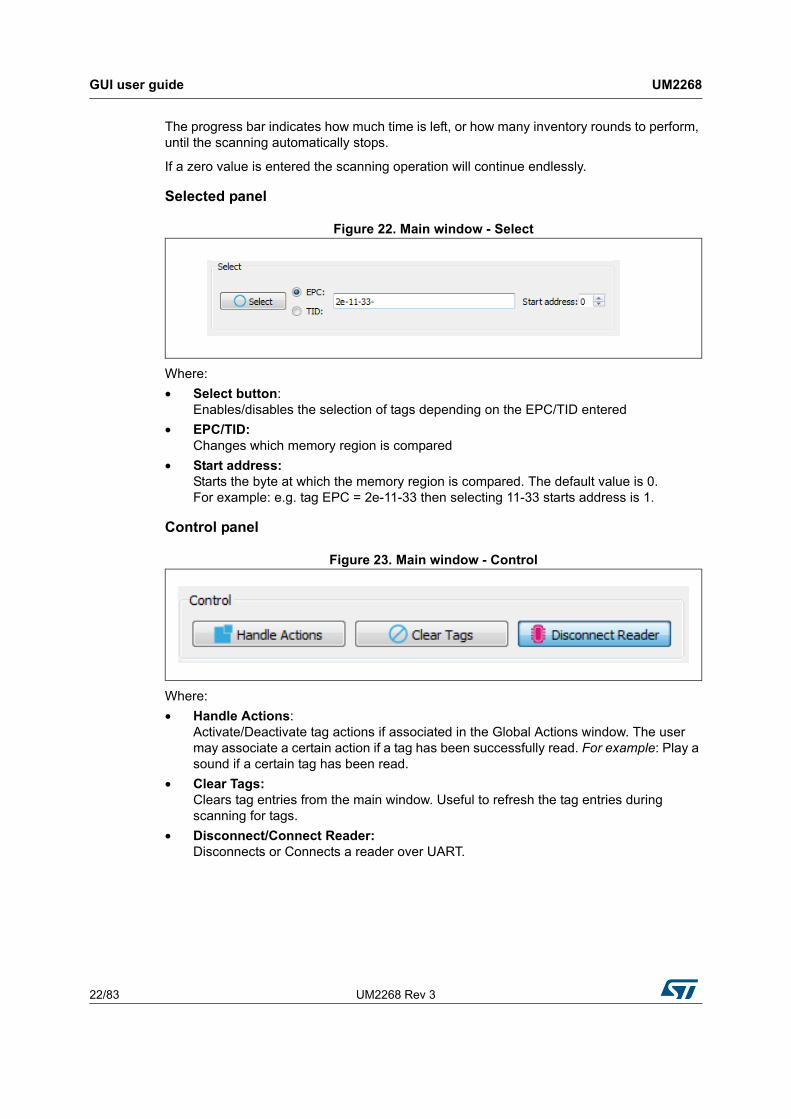
Scan panel
By clicking on the Start Scan button the reader starts to scan for tags.
Figure 21. Main window - Start scanning for Tags
On the right hand side of the scan button there is an entry field to define when the scan operation is stopped again.
There are two options:
• Second: After the defined time the scan operation is stopped automatically. The maximum number that can be entered is 600.
• #rounds: After the defined number of inventory rounds are completed the scan operation is stopped. The maximum number that can be entered is 600.
GUI user guide UM2268
22/83 UM2268 Rev 3
The progress bar indicates how much time is left, or how many inventory rounds to perform, until the scanning automatically stops.
If a zero value is entered the scanning operation will continue endlessly.
Selected panel
Figure 22. Main window - Select
Where:
• Select button: Enables/disables the selection of tags depending on the EPC/TID entered
• EPC/TID: Changes which memory region is compared
• Start address: Starts the byte at which the memory region is compared. The default value is 0. For example: e.g. tag EPC = 2e-11-33 then selecting 11-33 starts address is 1.
Control panel
Figure 23. Main window - Control
Where:
• Handle Actions: Activate/Deactivate tag actions if associated in the Global Actions window. The user may associate a certain action if a tag has been successfully read. For example: Play a sound if a certain tag has been read.
• Clear Tags: Clears tag entries from the main window. Useful to refresh the tag entries during scanning for tags.
• Disconnect/Connect Reader: Disconnects or Connects a reader over UART.

UM2268 Rev 3 23/83
UM2268 GUI user guide
81
2.2 Reader settings - EU profile
The reader software automatically selects the frequency profiles, which is needed to comply with local radio regulations. The reader configurations and diagnostic tools are accessible through the reader settings dialog. To access the reader settings dialog click on the Reader Settings button above the main window. Alternatively by right-clicking to the reader entry, a pop-up menu is displayed. Click on Reader Settings to enter the reader settings dialog. In addition a keyboard shortcut is defined. By pressing [Ctrl+s] on the keyboard the Reader Settings dialog opens.
The Reader Settings window is organized in three tabs:
• Settings: Change/modify basic reader settings.
• Diagnostics: Contains tools and features that are useful to analyze the RFID reader system. For instance activate a continuous modulation or outputting a constant wave signal.
• Tuning: Allows to control the carrier cancellation circuitry.
2.2.1 EU profile settings tab
Figure 24. EU profile reader Settings window: General tab

GUI user guide UM2268
24/83 UM2268 Rev 3
General panel
• Antenna Select: Select either Antenna 1 or Antenna 2 as the active antenna port depending on the antenna configuration. If the antenna is selected an entry field appears below to define the number of inventory rounds after which the active antenna port should be switched. The maximum number that can be entered is 99 rounds.
• RSSI mode: Defines when the RSSI of the tag is measured.
• Tag Scan Mode: Defines the next communication steps once the tag has replied with its EPC.
– Gen2 - Fast inventory: The Tag sends EPC number and reverts to READY state.
– Gen2 - Normal inventory: The Tag sends HANDLE and reverts to READY state. Gen2 - Normal Inventory with TID: Same as Normal Inventory with an additional readout of the TID memory. If this option is selected, a pull-down menu named “Select mode” appears, which allows to select the information (EPC, TID or both).
– ISO 6B: Scan for a ISO 6B Tag
• Inventory Delay: By changing the Inventory Delay [ms], an additional wait time is inserted between two consecutive inventory rounds. The maximum value is 20000 [ms].
• AutoAck feature checkbox: Enables the autoACK feature for tag inventories that automates sending the ACK command or the ACK and ReqRN command according to the Gen2 protocol. Depending on the tag scan mode selection above, AutoACK and Gen2 - fast inventory will send the ACK command after the RN16 and RN16 automatically while AUTOACK and Gen2 - normal inventory will send the ACK command after the RN16 and also the ReqRN command after the EPC response of the tag.
Supply options panel
In order to measure the power consumption of the ST25RU3993 you can change the device power mode and settings here.
• Auto voltage regulator: Internal voltage regulators maintain a certain drop-out voltage even with decreased supply/battery voltage.
• Device power mode: Allows to bring the reader IC into various supply power states.
• Device Bias Allows to change the bias setting for the entire IC resulting in less current consumption at the expense of performance.

UM2268 Rev 3 25/83
UM2268 GUI user guide
81
Tx Options panel
• External/Internal PA: This allows to switch between external or internal power amplifiers.
• Output level: The Output level slider changes the output power for the 0-dBm and the internal PA output (register 0x15, bits [4:0]). The output power may be changed by nominal 1 dB per step.
• TARI: Gen2 transmission setting. Changes the TX-Zero lengh to:
– 6.25 µs
– 12.5 µs
– 25 µs
Carrier Sense panel
If enabled the reader will sense if the next transmit frequency channel is free or already occupied by another reader.
• RSSI threshold: If the signal strength of the sensed carrier is below this threshold, the slot is considered free, and therefore will be used by the reader. The RSSI threshold can be entered from -40 dBm down to -80 dBm.
• Listen time: Carrier Sense duration. During this time the RSSI is measured repeatedly. The maximum value is then checked for threshold crossing.
• Idle time: Wait time between transmit frequency channel switch and performing Carrier Sense.
Rx Options panel
• Receive Gain: The receive gain slider adjusts the receive gain and/or receive attenuation of the reader. The slider affects register 0x0A.
• AGC Mode: Enables/Disables the automatic gain control feature of the ST25RU3993.
• Adaptive Sensitivity Section: This section allows to enable/disable adaptive receive gain/attenuation change. If enabled the receive gain will be automatically increased if no tags are found and decreased, if the tag RSSI is high.
• Interval: Defines after which number of inventory rounds the receive gain/attenuation is re-adjusted. The maximum value that can be entered is 99 rounds.
GUI user guide UM2268
26/83 UM2268 Rev 3
Gen2 Settings panel
• Link frequency: Changes the backscatter link frequency to:
– 40 kHz
– 160 kHz
– 213 kHz
– 256 kHz
– 320 kHz
– 640 kHz
• Coding: Changes the coding to:
– FM0
– Miller 2
– Miller 4
– Miller 8
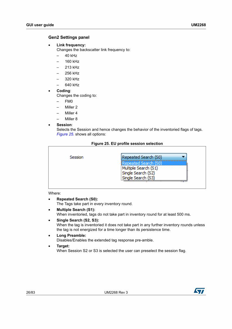
• Session: Selects the Session and hence changes the behavior of the inventoried flags of tags. Figure 25. shows all options:
Figure 25. EU profile session selection
Where:
• Repeated Search (S0): The Tags take part in every inventory round.
• Multiple Search (S1): When inventoried, tags do not take part in inventory round for at least 500 ms.
• Single Search (S2, S3): When the tag is inventoried it does not take part in any further inventory rounds unless the tag is not energized for a time longer than its persistence time.
• Long Preamble: Disables/Enables the extended tag response pre-amble.
• Target: When Session S2 or S3 is selected the user can preselect the session flag.
UM2268 Rev 3 27/83
UM2268 GUI user guide
81
Anti-collision settings panel
• Q: Defines the initial number of available anti-collision slots according to Gen2 protocol specification. The maximum value that can be entered is 15. If adaptive is activated the reader is adjusting the Q value according to the present tags in the read zone. The reader attempts to minimize the number of empty slots and the number of collisions (pre-amble errors).
• Max. query adjust: Maximum rounds (QueryRep) which are additionally performed. An inventory round is started with an Query command and collects tags in 2^Q slots. If collisions occur, some tags will not be inventoried. The inventory round will be extended with the number of defined QueryAdjust commands. Tags which have not been inventoried yet will participate in additional rounds with Q adjusted.
• Thresholds Up: The adjustment of Q is dependent on the occurred collisions. Q will be increased if the number of collisions is greater or equal than the number of slots multiplied by the defined Threshold Up value.
• Threshold down: The adjustment of Q is dependent on the occurred collisions. Q will be decreased if the number of collisions is lower than the number of slots multiplied by the defined Threshold Down value.
Note: If none of the above threshold criteria are met Q will remain unchanged.
GUI user guide UM2268
28/83 UM2268 Rev 3
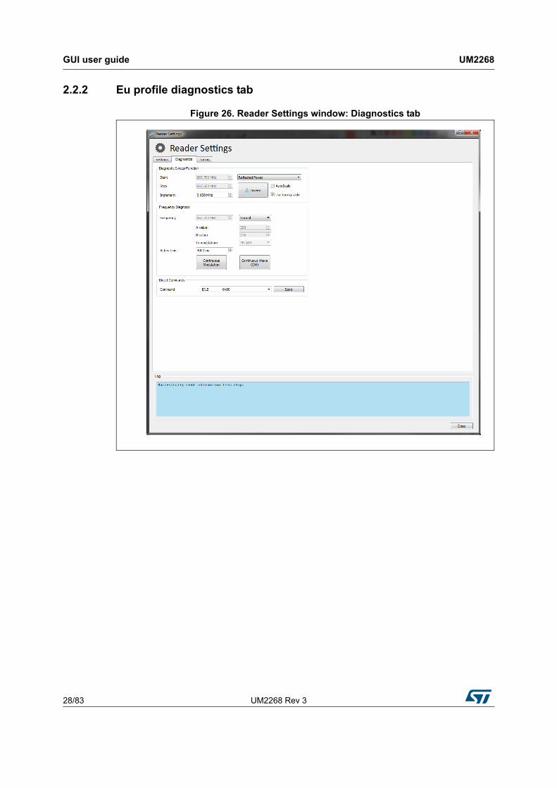
2.2.2 Eu profile diagnostics tab
Figure 26. Reader Settings window: Diagnostics tab
UM2268 Rev 3 29/83
UM2268 GUI user guide
81
Diagnostic Sweep Function
In the Diagnostic Sweep Function panel it is possible to run a reflected power sweep measurements across the select frequency range, or scan for the presence of an external carrier.
• Start: Start frequency of the frequency sweep in MHz.
• Stop: Stop frequency where the sweep should stop in MHz.
• Mode: Select one of the two available frequency sweep modes:
– Reflected Power
– RSSI. Scan frequency for the presence of an external carrier.
• Increment: Defines the frequency step size for each consecutive measurement in MHz and thus the number of measurement points.
• Sweep: Starts the frequency sweep for the defined Mode and frequency range.
• AutoScale: If activated the result chart is scaled automatically for best fit.
• Use tuning table: If activated the internally stored tuning table is used of the reflected power measurement.
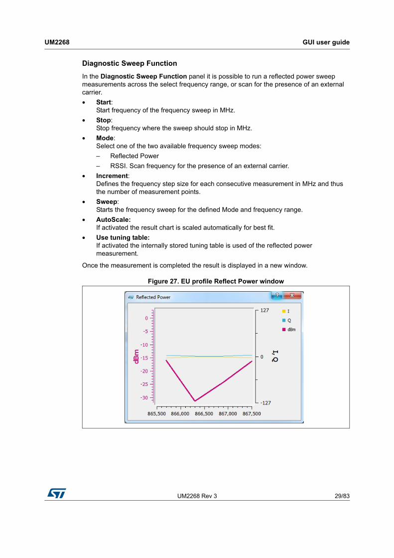
Once the measurement is completed the result is displayed in a new window.
Figure 27. EU profile Reflect Power window

GUI user guide UM2268
30/83 UM2268 Rev 3
Frequency Diagnosis panel
• Frequency: Defines the frequency at which the CW or modulated carrier is output.
• A value: Display the decimal value of the PLL A register
• B value: Displays the decimal value of the PLL B register
• TX modulation: Defines the current modulation type
• Active time: Defines the time the TX output is ON
• Continuous Wave (CW): Generates a continuous carrier wave at the selected frequency.
• Continuous Modulation: If set to normal this mode the reader continuously transmits a NAK command at the specified frequency for a given period of time.
– Pseudo Random: If this option is selected the reader outputs the carrier modulated by pseudo random.
– ETSI Test Mode: With this option the reader outputs the test signal defined in EN 302 208.
Direct Commands panel
• Direct Command: A selection menu from which direct commands may be selected and transmitted.
UM2268 Rev 3 31/83
UM2268 GUI user guide
81
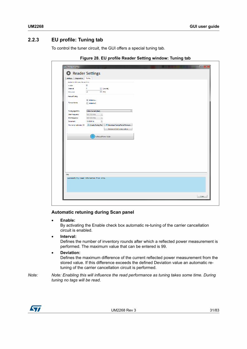
2.2.3 EU profile: Tuning tab
To control the tuner circuit, the GUI offers a special tuning tab.
Figure 28. EU profile Reader Setting window: Tuning tab
Automatic retuning during Scan panel
• Enable: By activating the Enable check box automatic re-tuning of the carrier cancellation circuit is enabled.
• Interval: Defines the number of inventory rounds after which a reflected power measurement is performed. The maximum value that can be entered is 99.
• Deviation: Defines the maximum difference of the current reflected power measurement from the stored value. If this difference exceeds the defined Deviation value an automatic re-tuning of the carrier cancellation circuit is performed.
Note: Note: Enabling this will influence the read performance as tuning takes some time. During tuning no tags will be read.
GUI user guide UM2268
32/83 UM2268 Rev 3
Manual tuning panel
• Tune antenna: Activating the check box for Antenna 1 or Antenna 2 includes the corresponding antenna in the creation of the tuning table.
Note: Note to add a 50 ohm antenna or load to the antenna port selected here.
• Tuning algorithm:
– Climb current [fast]: This algorithm searches for a minimum of reflected power by using the current configuration of the carrier cancellation circuit as starting point.
• Start Frequency: Defines the tuning start frequency.
• Stop Frequency: Defines the tuning stop frequency.
• Increment: Defines the tuning frequency increment.
• Creating Tuning File: By clicking on this button the process of creating a tuning file for the defined frequency range and increment is started. The tuning file is a look-up table that defines for each tuning frequency the configuration of the carrier cancellation circuit. The carrier cancellation circuit configuration can be described by three capacitor values. The tuning file will be used during the normal scan operation. Every time the reader changes its transmit frequency the tuning file is queried to retrieve and apply the appropriate configuration of the carrier cancellation circuit for that particular frequency. For best sensitivity of the reader it is recommended to keep the antenna and its environment static while the creation of the tuning files is in progress. The time needed for the creation of the tuning files depends on the selected algorithm and the number of tuning frequencies. The current status of the tuning file creation can be seen in the logging at the bottom of the tuning tab. Once the creation of the tuning file is completed the user is prompted with a file dialog to choose a file location where the tuning file should be stored.
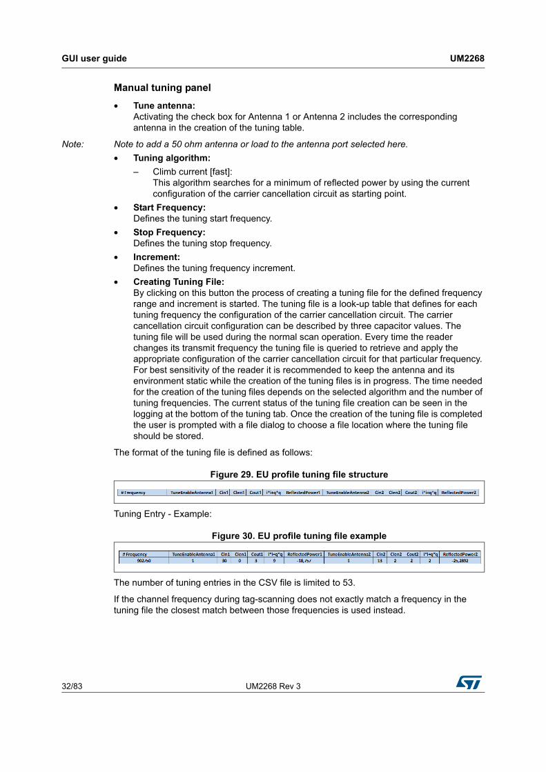
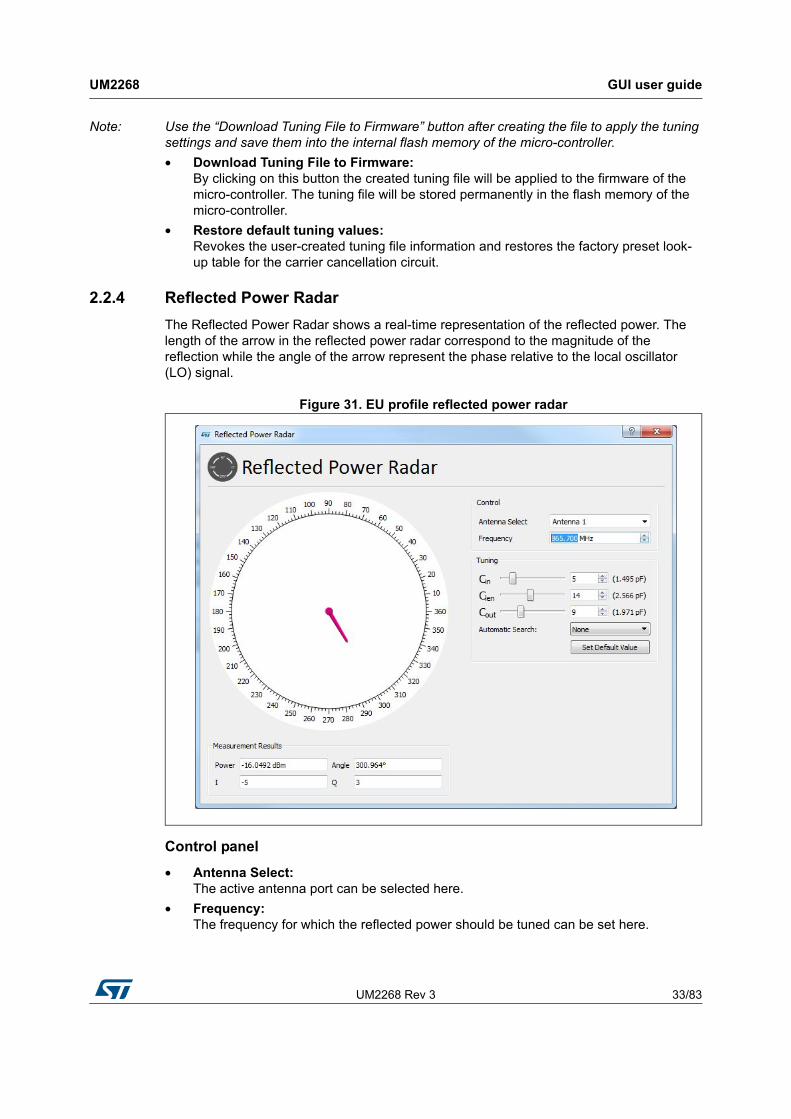
The format of the tuning file is defined as follows:
Figure 29. EU profile tuning file structure
Tuning Entry - Example:
Figure 30. EU profile tuning file example
The number of tuning entries in the CSV file is limited to 53.
If the channel frequency during tag-scanning does not exactly match a frequency in the tuning file the closest match between those frequencies is used instead.
UM2268 Rev 3 33/83
UM2268 GUI user guide
81
Note: Use the “Download Tuning File to Firmware” button after creating the file to apply the tuning settings and save them into the internal flash memory of the micro-controller.
• Download Tuning File to Firmware: By clicking on this button the created tuning file will be applied to the firmware of the micro-controller. The tuning file will be stored permanently in the flash memory of the micro-controller.
• Restore default tuning values: Revokes the user-created tuning file information and restores the factory preset look-up table for the carrier cancellation circuit.
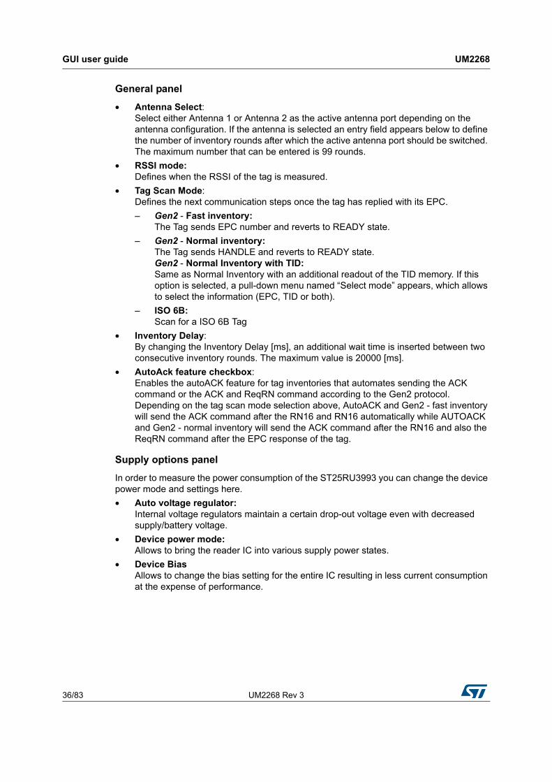
2.2.4 Reflected Power Radar
The Reflected Power Radar shows a real-time representation of the reflected power. The length of the arrow in the reflected power radar correspond to the magnitude of the reflection while the angle of the arrow represent the phase relative to the local oscillator (LO) signal.
Figure 31. EU profile reflected power radar
Control panel
• Antenna Select: The active antenna port can be selected here.
• Frequency: The frequency for which the reflected power should be tuned can be set here.

GUI user guide UM2268
34/83 UM2268 Rev 3
Tuning panel
• Cin: This slider changes the capacitance value of the input shunt capacitor of the carrier cancellation circuit.
• Clen: This slider changes the capacitance value of the series capacitor of the carrier cancellation circuit.
• Cout: This slider changes the capacitance value of the output shunt capacitor of the carrier cancellation circuit.
• Autom. Search: This pull-down menu defines which algorithm will be used to search for the reflected power minimum.
• Climb Points [slow]: Performs multiple reflected power minimum searches starting from different pre-defined capacitor configurations. The automatic algorithm stops when all individual searches are completed. The reflected power measurement results of all individual searches are compared against each other and the capacitor configurations for the overall minimum reflected power is applied.
• Set Default Value: Reverts the configuration of all variable capacitors to their default value for a default frequency. If the current active frequency is not a default frequency the capacitor values are set to step 15 (1.495 pF).
Measurement Results panel
• Power: Shows the reflected power measurement result in a numeric form. The reflected power measurement is performed by ST25RU3993.
• Angle: Shows the phase of the reflected power relative to the local oscillator signal.
• I: ADC results for the in-phase component of the reflected power measured by ST25RU3993
• Q: ADC results for the quadrature component of the reflected power measured by ST25RU3993

UM2268 Rev 3 35/83
UM2268 GUI user guide
81
2.3 Reader setting - USA profile
The reader software automatically selects the frequency profiles, which is needed to comply with local radio regulations. The reader configurations and diagnostic tools are accessible through the reader settings dialog. To access the reader settings dialog click on the Reader Settings button above the main window. Alternatively by right-clicking to the reader entry, a pop-up menu is displayed. Click on Reader Settings to enter the reader settings dialog. In addition a keyboard shortcut is defined. By pressing [Ctrl+s] on the keyboard the Reader Settings dialog opens.
The Reader Settings window is organized in three tabs:
• Settings: Change/modify basic reader settings.
• Diagnostics: Contains tools and features that are useful to analyze the RFID reader system. For instance activate a continuous modulation or outputting a constant wave signal.
• Tuning: Allows to control the carrier cancellation circuitry.
2.3.1 USA profile settings tab
Figure 32. USA profile reader Settings window: General tab
GUI user guide UM2268
36/83 UM2268 Rev 3
General panel
• Antenna Select: Select either Antenna 1 or Antenna 2 as the active antenna port depending on the antenna configuration. If the antenna is selected an entry field appears below to define the number of inventory rounds after which the active antenna port should be switched. The maximum number that can be entered is 99 rounds.
• RSSI mode: Defines when the RSSI of the tag is measured.
• Tag Scan Mode: Defines the next communication steps once the tag has replied with its EPC.
– Gen2 - Fast inventory: The Tag sends EPC number and reverts to READY state.
– Gen2 - Normal inventory: The Tag sends HANDLE and reverts to READY state. Gen2 - Normal Inventory with TID: Same as Normal Inventory with an additional readout of the TID memory. If this option is selected, a pull-down menu named “Select mode” appears, which allows to select the information (EPC, TID or both).
– ISO 6B: Scan for a ISO 6B Tag
• Inventory Delay: By changing the Inventory Delay [ms], an additional wait time is inserted between two consecutive inventory rounds. The maximum value is 20000 [ms].
• AutoAck feature checkbox: Enables the autoACK feature for tag inventories that automates sending the ACK command or the ACK and ReqRN command according to the Gen2 protocol. Depending on the tag scan mode selection above, AutoACK and Gen2 - fast inventory will send the ACK command after the RN16 and RN16 automatically while AUTOACK and Gen2 - normal inventory will send the ACK command after the RN16 and also the ReqRN command after the EPC response of the tag.
Supply options panel
In order to measure the power consumption of the ST25RU3993 you can change the device power mode and settings here.
• Auto voltage regulator: Internal voltage regulators maintain a certain drop-out voltage even with decreased supply/battery voltage.
• Device power mode: Allows to bring the reader IC into various supply power states.
• Device Bias Allows to change the bias setting for the entire IC resulting in less current consumption at the expense of performance.
UM2268 Rev 3 37/83
UM2268 GUI user guide
81
Tx Options panel
• External/Internal PA: This allows to switch between external or internal power amplifiers.
• Output level: The Output level slider changes the output power for the 0-dBm and the internal PA output (register 0x15, bits [4:0]). The output power may be changed by nominal 1 dB per step.
• TARI: Gen2 transmission setting. Changes the TX-Zero lengh to:
– 6.25 µs
– 12.5 µs
– 25 µs
Carrier Sense Panel If enabled the reader will sense if the next transmit frequency channel is free or already occupied by another reader.
• RSSI threshold: If the signal strength of the sensed carrier is below this threshold, the slot is considered free, and therefore will be used by the reader. The RSSI threshold can be entered from -40 dBm down to -80 dBm.
• Listen time: Carrier Sense duration. During this time the RSSI is measured repeatedly. The maximum value is then checked for threshold crossing.
• Idle time: Wait time between transmit frequency channel switch and performing Carrier Sense.
Rx Options panel
• Receive Gain: The receive gain slider adjusts the receive gain and/or receive attenuation of the reader. The slider affects register 0x0A.
• AGC Mode: Enables/Disables the automatic gain control feature of the ST25RU3993.
• Adaptive Sensitivity Section: This section allows to enable/disable adaptive receive gain/attenuation change. If enabled the receive gain will be automatically increased if no tags are found and decreased, if the tag RSSI is high.
• Interval: Defines after which number of inventory rounds the receive gain/attenuation is re-adjusted. The maximum value that can be entered is 99 rounds.
GUI user guide UM2268
38/83 UM2268 Rev 3
Gen2 settings panel
• Link frequency: Changes the backscatter link frequency to:
– 40 kHz
– 160 kHz
– 213 kHz
– 256 kHz
– 320 kHz
– 640 kHz
• Coding: Changes the coding to:
– FM0
– Miller 2
– Miller 4
– Miller 8
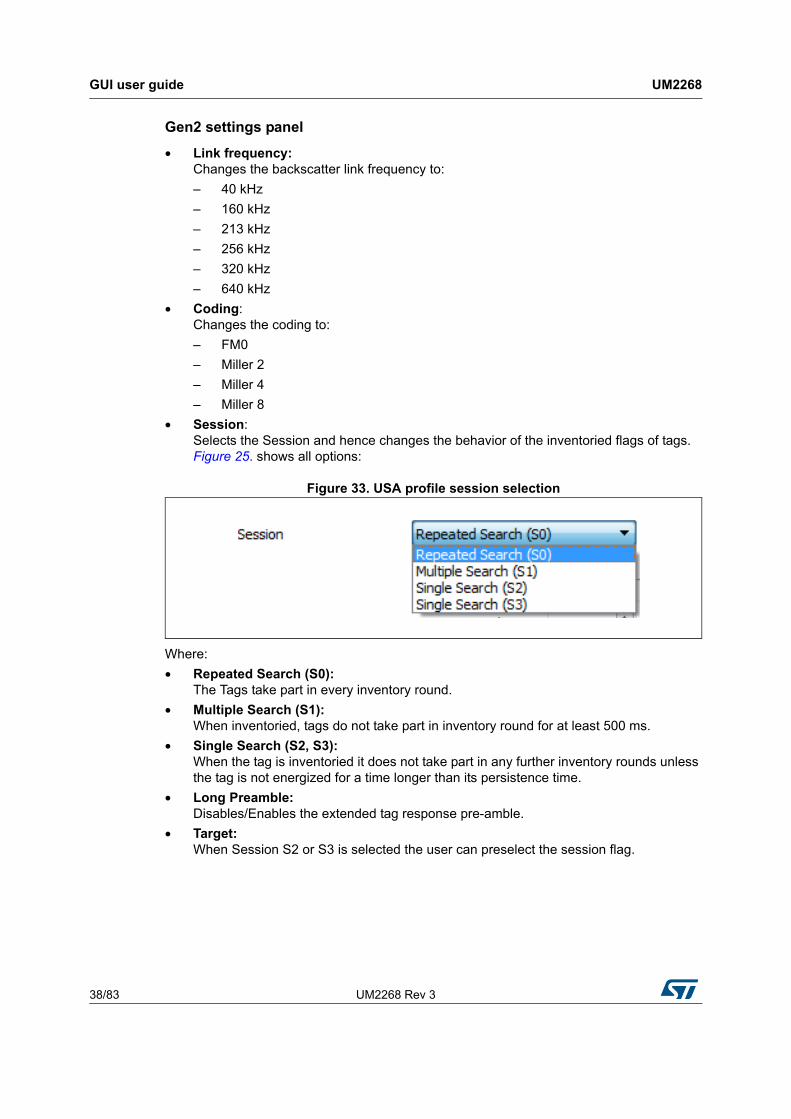
• Session: Selects the Session and hence changes the behavior of the inventoried flags of tags. Figure 25. shows all options:
Figure 33. USA profile session selection
Where:
• Repeated Search (S0): The Tags take part in every inventory round.
• Multiple Search (S1): When inventoried, tags do not take part in inventory round for at least 500 ms.
• Single Search (S2, S3): When the tag is inventoried it does not take part in any further inventory rounds unless the tag is not energized for a time longer than its persistence time.
• Long Preamble: Disables/Enables the extended tag response pre-amble.
• Target: When Session S2 or S3 is selected the user can preselect the session flag.
UM2268 Rev 3 39/83
UM2268 GUI user guide
81
Anti-collision settings panel
• Q: Defines the initial number of available anti-collision slots according to Gen2 protocol specification. The maximum value that can be entered is 15. if adaptive is activated the reader is adjusting the Q value according to the present tags in the read zone. The reader attempts to minimize the number of empty slots and the number of collisions (pre-amble errors).
• Max. query adjust: Maximum rounds (QueryRep) which are additionally performed. An inventory round is started with an Query command and collects tags in 2^Q slots. If collisions occur, some tags will not be inventoried. The inventory round will be extended with the number of defined QueryAdjust commands. Tags which are not inventoried yet will participate in additional rounds with Q adjusted.
• Thresholds Up: The adjustment of Q is dependent on the occurred collisions. Q will be increased if the number of collisions is greater or equal than the number of slots multiplied by the defined Threshold Up value.
• Threshold down: The adjustment of Q is dependent on the occurred collisions. Q will be decreased if the number of collisions is lower than the number of slots multiplied by the defined Threshold Down value.
Note: If none of the above threshold criteria are met Q will remain unchanged.
GUI user guide UM2268
40/83 UM2268 Rev 3
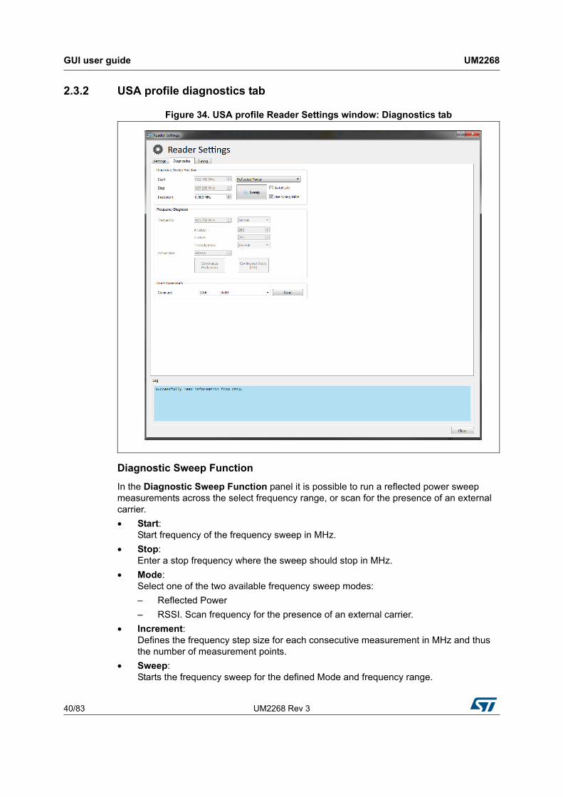
2.3.2 USA profile diagnostics tab
Figure 34. USA profile Reader Settings window: Diagnostics tab
Diagnostic Sweep Function
In the Diagnostic Sweep Function panel it is possible to run a reflected power sweep measurements across the select frequency range, or scan for the presence of an external carrier.
• Start: Start frequency of the frequency sweep in MHz.
• Stop: Enter a stop frequency where the sweep should stop in MHz.
• Mode: Select one of the two available frequency sweep modes:
– Reflected Power
– RSSI. Scan frequency for the presence of an external carrier.
• Increment: Defines the frequency step size for each consecutive measurement in MHz and thus the number of measurement points.
• Sweep: Starts the frequency sweep for the defined Mode and frequency range.
UM2268 Rev 3 41/83
UM2268 GUI user guide
81
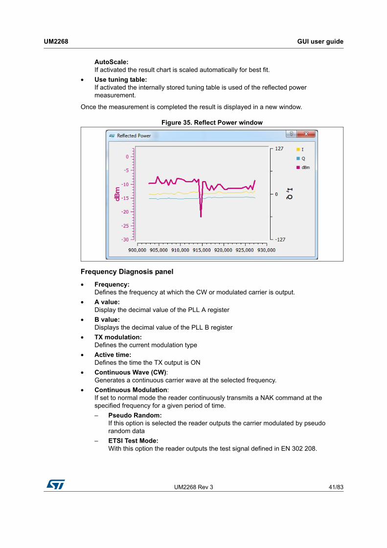
AutoScale: If activated the result chart is scaled automatically for best fit.
• Use tuning table: If activated the internally stored tuning table is used of the reflected power measurement.
Once the measurement is completed the result is displayed in a new window.
Figure 35. Reflect Power window
Frequency Diagnosis panel
• Frequency: Defines the frequency at which the CW or modulated carrier is output.
• A value: Display the decimal value of the PLL A register
• B value: Displays the decimal value of the PLL B register
• TX modulation: Defines the current modulation type
• Active time: Defines the time the TX output is ON
• Continuous Wave (CW): Generates a continuous carrier wave at the selected frequency.
• Continuous Modulation: If set to normal mode the reader continuously transmits a NAK command at the specified frequency for a given period of time.
– Pseudo Random: If this option is selected the reader outputs the carrier modulated by pseudo random data
– ETSI Test Mode: With this option the reader outputs the test signal defined in EN 302 208.
GUI user guide UM2268
42/83 UM2268 Rev 3
Direct Commands panel
• Direct Command: A selection menu from which direct commands may be selected and transmitted.
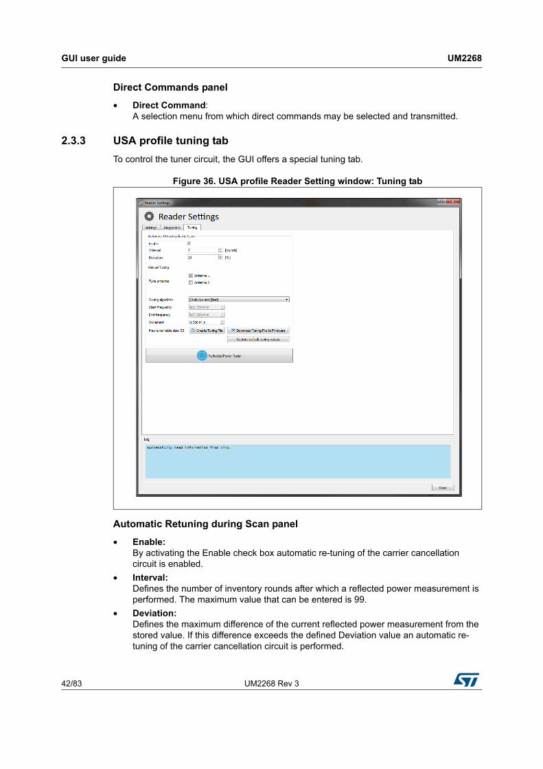
2.3.3 USA profile tuning tab
To control the tuner circuit, the GUI offers a special tuning tab.
Figure 36. USA profile Reader Setting window: Tuning tab
Automatic Retuning during Scan panel
• Enable: By activating the Enable check box automatic re-tuning of the carrier cancellation circuit is enabled.
• Interval: Defines the number of inventory rounds after which a reflected power measurement is performed. The maximum value that can be entered is 99.
• Deviation: Defines the maximum difference of the current reflected power measurement from the stored value. If this difference exceeds the defined Deviation value an automatic re-tuning of the carrier cancellation circuit is performed.
UM2268 Rev 3 43/83
UM2268 GUI user guide
81
Note: Note: Enabling this will influence the read performance as tuning takes some time. During tuning no tags will be read.
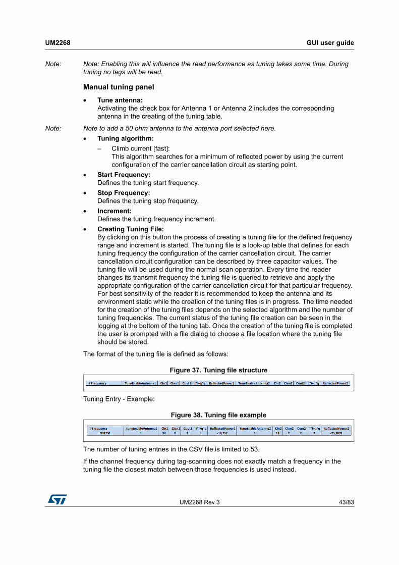
Manual tuning panel
• Tune antenna: Activating the check box for Antenna 1 or Antenna 2 includes the corresponding antenna in the creating of the tuning table.
Note: Note to add a 50 ohm antenna to the antenna port selected here.
• Tuning algorithm:
– Climb current [fast]: This algorithm searches for a minimum of reflected power by using the current configuration of the carrier cancellation circuit as starting point.
• Start Frequency: Defines the tuning start frequency.
• Stop Frequency: Defines the tuning stop frequency.
• Increment: Defines the tuning frequency increment.
• Creating Tuning File: By clicking on this button the process of creating a tuning file for the defined frequency range and increment is started. The tuning file is a look-up table that defines for each tuning frequency the configuration of the carrier cancellation circuit. The carrier cancellation circuit configuration can be described by three capacitor values. The tuning file will be used during the normal scan operation. Every time the reader changes its transmit frequency the tuning file is queried to retrieve and apply the appropriate configuration of the carrier cancellation circuit for that particular frequency. For best sensitivity of the reader it is recommended to keep the antenna and its environment static while the creation of the tuning files is in progress. The time needed for the creation of the tuning files depends on the selected algorithm and the number of tuning frequencies. The current status of the tuning file creation can be seen in the logging at the bottom of the tuning tab. Once the creation of the tuning file is completed the user is prompted with a file dialog to choose a file location where the tuning file should be stored.
The format of the tuning file is defined as follows:
Figure 37. Tuning file structure
Tuning Entry - Example:
Figure 38. Tuning file example
The number of tuning entries in the CSV file is limited to 53.
If the channel frequency during tag-scanning does not exactly match a frequency in the tuning file the closest match between those frequencies is used instead.
GUI user guide UM2268
44/83 UM2268 Rev 3
Note: Use the “Download Tuning File to Firmware” button after creating the file to apply the tuning settings and save them into the internal flash memory of the micro-controller.
• Download Tuning File to Firmware: By clicking on this button the created tuning file will be applied to the firmware of the micro-controller. The tuning file will be stored permanently in the flash memory of the micro-controller.
• Restore default tuning values: Revokes the user-created tuning file information and restores the factory preset look-up table for the carrier cancellation circuit.
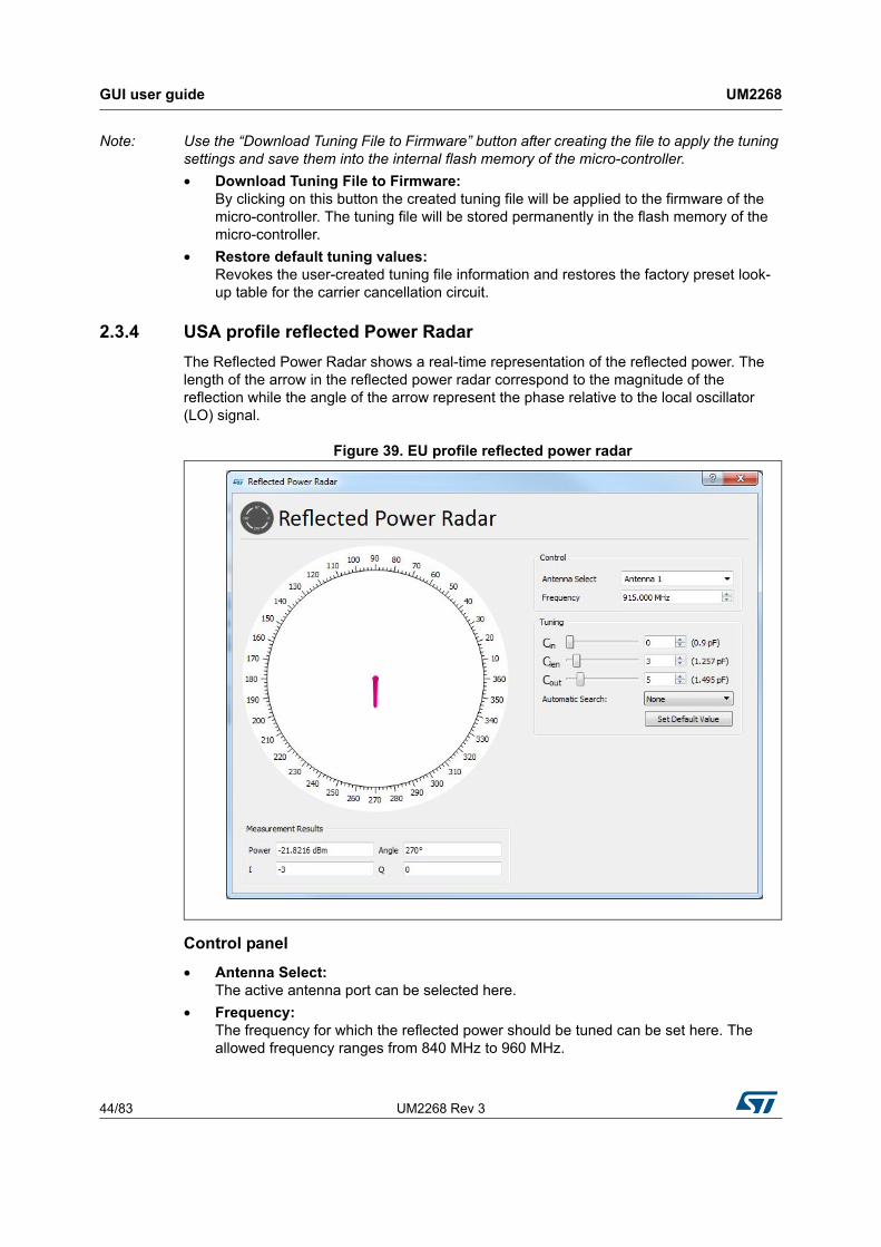
2.3.4 USA profile reflected Power Radar
The Reflected Power Radar shows a real-time representation of the reflected power. The length of the arrow in the reflected power radar correspond to the magnitude of the reflection while the angle of the arrow represent the phase relative to the local oscillator (LO) signal.
Figure 39. EU profile reflected power radar
Control panel
• Antenna Select: The active antenna port can be selected here.
• Frequency: The frequency for which the reflected power should be tuned can be set here. The allowed frequency ranges from 840 MHz to 960 MHz.

UM2268 Rev 3 45/83
UM2268 GUI user guide
81
Tuning panel
• Cin: This slider changes the capacitance value of the input shunt capacitor of the carrier cancellation circuit.
• Clen: This slider changes the capacitance value of the series capacitor of the carrier cancellation circuit.
• Cout: This slider changes the capacitance value of the output shunt capacitor of the carrier cancellation circuit.
• Autom. Search: This pull-down menu defines which algorithm will be used to search for the reflected power minimum.
• Climb Current [fast]: Searches for a reflected power minimum starting from the current configuration of the carrier cancellation circuit. To find the minimum the variable capacitors are adjusted and a measurement of the resulting reflected power is initiated. The automatic algorithm stops when capacitor configurations are found that result to the lowest reflected power. The best capacitor configurations are automatically applied. Changing the three capacitor values manually defines a new starting point for the search.
• Climb Points [slow]: Performs multiple reflected power minimum searches starting from different pre-defined capacitor configurations. The automatic algorithm stops when all individual searches are completed. The reflected power measurement results of all individual searches are compared against each other and the capacitor configurations for the overall minimum reflected power is applied.
• Set Default Value: Reverts the configuration of all variable capacitors to their default value for a default frequency. If the current active frequency is not a default frequency the capacitor values are set to step 15 (1.495 pF).
Measurement Results panel
• Power: Shows the reflected power measurement result in a numeric form. The reflected power measurement is performed by ST25RU3993.
• Angle: Shows the phase of the reflected power relative to the local oscillator signal.
• I: ADC results for the in-phase component of the reflected power measured by ST25RU3993
• Q: ADC results for the quadrature component of the reflected power measured by ST25RU3993
GUI user guide UM2268
46/83 UM2268 Rev 3
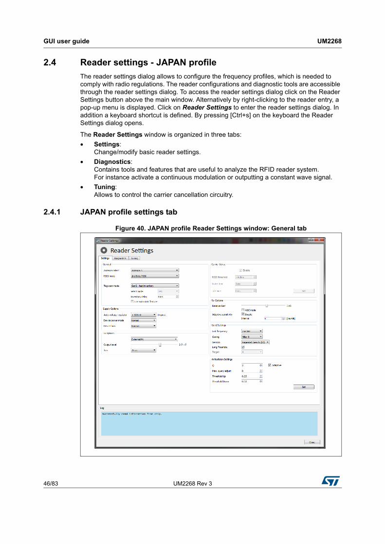
2.4 Reader settings - JAPAN profile
The reader settings dialog allows to configure the frequency profiles, which is needed to comply with radio regulations. The reader configurations and diagnostic tools are accessible through the reader settings dialog. To access the reader settings dialog click on the Reader Settings button above the main window. Alternatively by right-clicking to the reader entry, a pop-up menu is displayed. Click on Reader Settings to enter the reader settings dialog. In addition a keyboard shortcut is defined. By pressing [Ctrl+s] on the keyboard the Reader Settings dialog opens.
The Reader Settings window is organized in three tabs:
• Settings: Change/modify basic reader settings.
• Diagnostics: Contains tools and features that are useful to analyze the RFID reader system. For instance activate a continuous modulation or outputting a constant wave signal.
• Tuning: Allows to control the carrier cancellation circuitry.
2.4.1 JAPAN profile settings tab
Figure 40. JAPAN profile Reader Settings window: General tab
UM2268 Rev 3 47/83
UM2268 GUI user guide
81
General panel
• Antenna Select: Select either Antenna 1 or Antenna 2 as the active antenna port depending on the antenna configuration. If the antenna is selected an entry field appears below to define the number of inventory rounds after which the active antenna port should be switched. The maximum number that can be entered is 99 rounds.
• RSSI mode: Defines when the RSSI of the tag is measured.
• Tag Scan Mode: Defines the next communication steps once the tag has replied with its EPC.
– Gen2 - Fast inventory: The Tag sends EPC number and reverts to READY state.
– Gen2 - Normal inventory: The Tag sends HANDLE and reverts to READY state. Gen2 - Normal Inventory with TID: Same as Normal Inventory with an additional readout of the TID memory. If this option is selected, a pull-down menu named “Select mode” appears, which allows to select the information (EPC, TID or both).
– ISO 6B: Scan for a ISO 6B Tag
• Inventory Delay: By changing the Inventory Delay [ms], an additional wait time is inserted between two consecutive inventory rounds. The maximum value is 20000 [ms].
• AutoAck feature checkbox: Enables the autoACK feature for tag inventories that automates sending the ACK command or the ACK and ReqRN command according to the Gen2 protocol. Depending on the tag scan mode selection above, AutoACK and Gen2 - fast inventory will send the ACK command after the RN16 and RN16 automatically while AUTOACK and Gen2 - normal inventory will send the ACK command after the RN16 and also the ReqRN command after the EPC response of the tag.
Supply options panel
In order to measure the power consumption of the ST25RU3993 you can change the device power mode and settings here.
• Auto voltage regulator: Internal voltage regulators maintain a certain drop-out voltage even with decreased supply/battery voltage.
• Device power mode: Allows to bring the reader IC into various supply power states.
• Device Bias Allows to change the bias setting for the entire IC resulting in less current consumption at the expense of performance.
GUI user guide UM2268
48/83 UM2268 Rev 3
Tx Options panel
• External/Internal PA: This allows to switch between external or internal power amplifiers.
• Output level: The Output level slider changes the output power for the 0-dBm and the internal PA output (register 0x15, bits [4:0]). The output power may be changed by nominal 1 dB per step.
• TARI: Gen2 transmission setting. Changes the TX-Zero lengh to:
– 6.25 µs
– 12.5 µs
– 25 µs
Carrier Sense panel If enabled the reader will sense if the next transmit frequency channel is free or already occupied by another reader.
• RSSI threshold: If the signal strength of the sensed carrier is below this threshold, the slot is considered free, and therefore will be used by the reader. The RSSI threshold can be entered from -40 dBm down to -80 dBm.
• Listen time: Carrier Sense duration. During this time the RSSI is measured repeatedly. The maximum value is then checked for threshold crossing.
• Idle time: Wait time between transmit frequency channel switch and performing Carrier Sense.
Rx options panel
• Receive Gain: The receive gain slider adjusts the receive gain and/or receive attenuation of the reader. The slider affects register 0x0A.
• AGC Mode: Enables/Disables the automatic gain control feature of the ST25RU3993.
• Adaptive Sensitivity Section: This section allows to enable/disable adaptive receive gain/attenuation change. If enabled the receive gain will be automatically increased if no tags are found and decreased, if the tag RSSI is high.
• Interval: Defines after which number of inventory rounds the receive gain/attenuation is re-adjusted. The maximum value that can be entered is 99 rounds.
UM2268 Rev 3 49/83
UM2268 GUI user guide
81
Gen2 settings panel
• Link frequency: Changes the backscatter link frequency to:
– 40 kHz
– 160 kHz
– 213 kHz
– 256 kHz
– 320 kHz
– 640 kHz
• Coding: Changes the coding to:
– FM0
– Miller 2
– Miller 4
– Miller 8
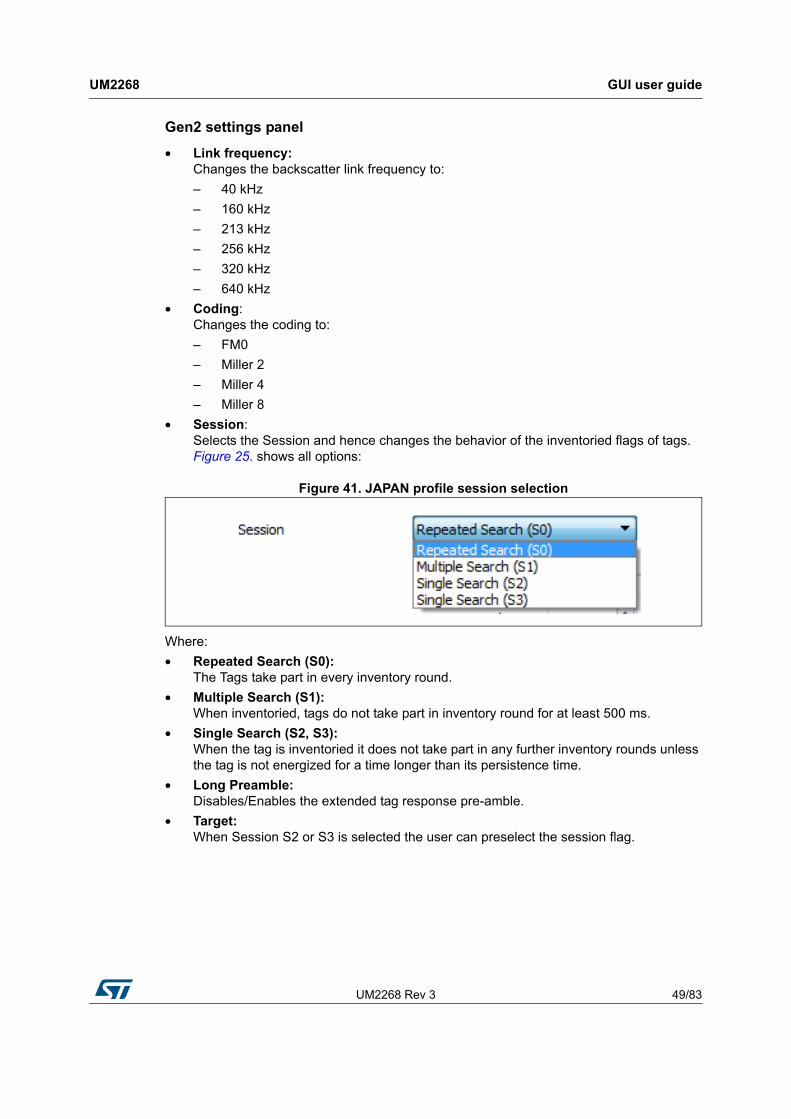
• Session: Selects the Session and hence changes the behavior of the inventoried flags of tags. Figure 25. shows all options:
Figure 41. JAPAN profile session selection
Where:
• Repeated Search (S0): The Tags take part in every inventory round.
• Multiple Search (S1): When inventoried, tags do not take part in inventory round for at least 500 ms.
• Single Search (S2, S3): When the tag is inventoried it does not take part in any further inventory rounds unless the tag is not energized for a time longer than its persistence time.
• Long Preamble: Disables/Enables the extended tag response pre-amble.
• Target: When Session S2 or S3 is selected the user can preselect the session flag.
GUI user guide UM2268
50/83 UM2268 Rev 3
Anti-collision settings panel
• Q: Defines the initial number of available anti-collision slots according to Gen2 protocol specification. The maximum value that can be entered is 15. if adaptive is activated the reader is adjusting the Q value according to the present tags in the read zone. The reader attempts to minimize the number of empty slots and the number of collisions (pre-amble errors).
• Max. query adjust: Maximum rounds (QueryRep) which are additionally performed. An inventory round is started with an Query command and collects tags in 2^Q slots. If collisions occur, some tags will not be inventoried. The inventory round will be extended with the number of defined QueryAdjust commands. Tags which are not inventoried yet will participate in additional rounds with Q adjusted.
• Thresholds Up: The adjustment of Q is dependent on the occurred collisions. Q will be increased if the number of collisions is greater or equal than the number of slots multiplied by the defined Threshold Up value.
• Threshold down: The adjustment of Q is dependent on the occurred collisions. Q will be decreased if the number of collisions is lower than the number of slots multiplied by the defined Threshold Down value.
Note: If none of the above threshold criteria are met Q will remain unchanged.
UM2268 Rev 3 51/83
UM2268 GUI user guide
81
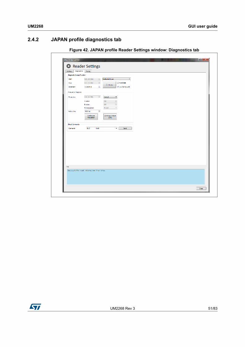
2.4.2 JAPAN profile diagnostics tab
Figure 42. JAPAN profile Reader Settings window: Diagnostics tab
GUI user guide UM2268
52/83 UM2268 Rev 3
Diagnostic Sweep Function
In the Diagnostic Sweep Function panel it is possible to run a reflected power sweep measurements across the select frequency range, or scan for the presence of an external carrier.
• Start: Start frequency of the frequency sweep in MHz.
• Stop: Stop frequency where the sweep should stop in MHz.
• Mode: Select one of the two available frequency sweep modes:
– Reflected Power
– RSSI. Scan frequency for the presence of an external carrier.
• Increment: Defines the frequency step size for each consecutive measurement in MHz and thus the number of measurement points.
• Sweep: Starts the frequency sweep for the defined Mode and frequency range.
• AutoScale: If activated the result chart is scaled automatically for best fit.
• Use tuning table: If activated the internally stored tuning table is used of the reflected power measurement.
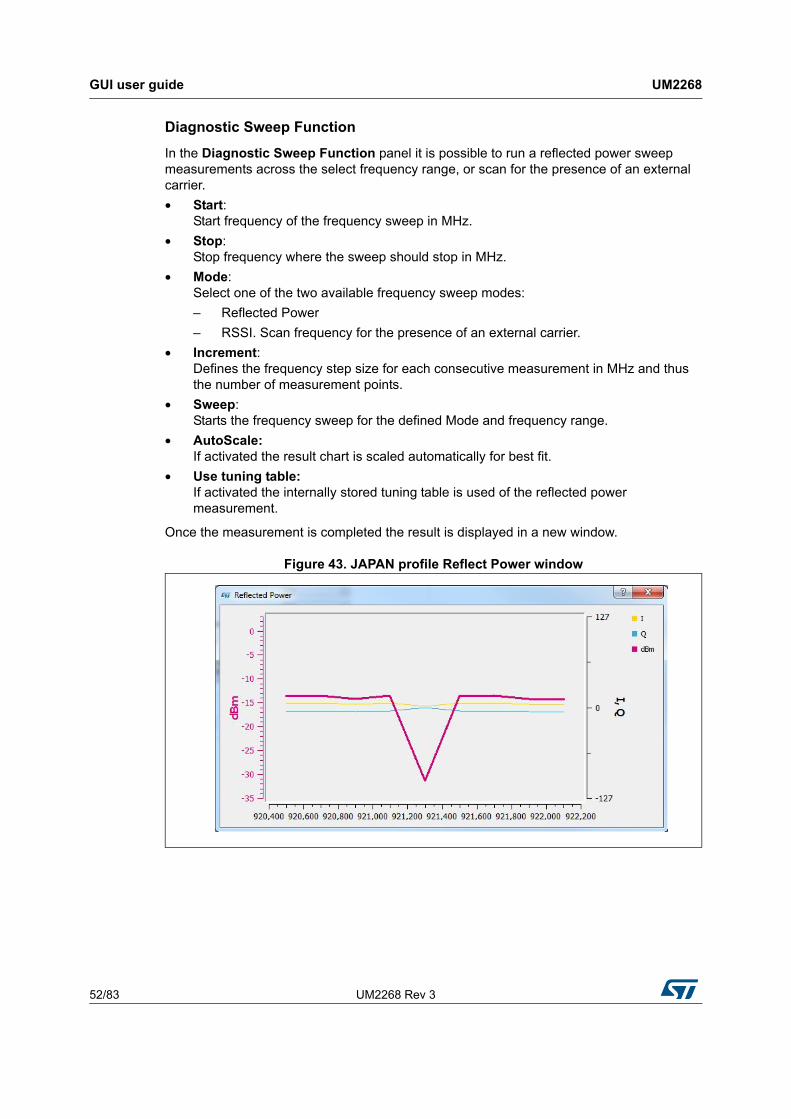
Once the measurement is completed the result is displayed in a new window.
Figure 43. JAPAN profile Reflect Power window

UM2268 Rev 3 53/83
UM2268 GUI user guide
81
Frequency Diagnosis panel
• Frequency: Defines the frequency at which the CW or modulated carrier is output.
• A value: Display the decimal value of the PLL A register
• B value: Displays the decimal value of the PLL B register
• TX modulation: Defines the current modulation type
• Active time: Defines the time the TX output is ON
• Continuous Wave (CW): Generates a continuous carrier wave at the selected frequency.
• Continuous Modulation: If set to normal mode the reader continuously transmits a NAK command at the specified frequency for a given period of time.
– Pseudo Random: If this option is selected the reader outputs the carrier modulated by pseudo random data
– ETSI Test Mode: With this option the reader outputs the test signal defined in EN 302 208.
Direct Commands panel
• Direct Command: A selection menu from which direct commands may be selected and transmitted.
GUI user guide UM2268
54/83 UM2268 Rev 3
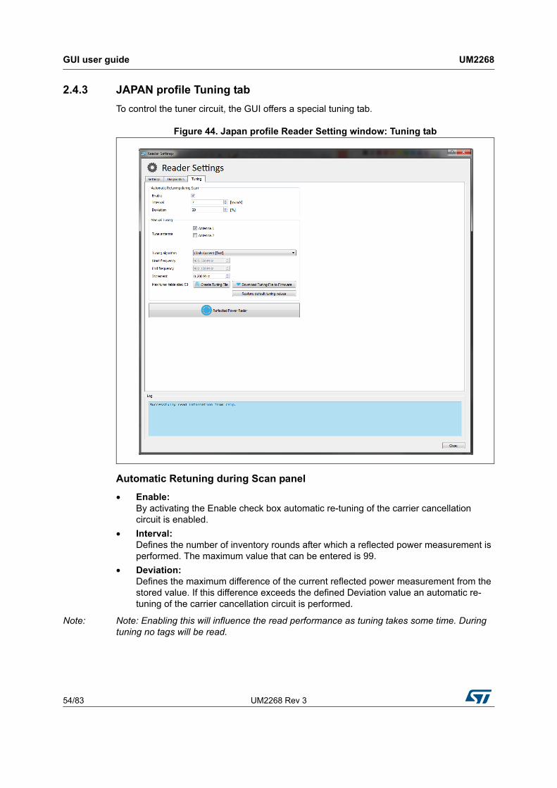
2.4.3 JAPAN profile Tuning tab
To control the tuner circuit, the GUI offers a special tuning tab.
Figure 44. Japan profile Reader Setting window: Tuning tab
Automatic Retuning during Scan panel
• Enable: By activating the Enable check box automatic re-tuning of the carrier cancellation circuit is enabled.
• Interval: Defines the number of inventory rounds after which a reflected power measurement is performed. The maximum value that can be entered is 99.
• Deviation: Defines the maximum difference of the current reflected power measurement from the stored value. If this difference exceeds the defined Deviation value an automatic re-tuning of the carrier cancellation circuit is performed.
Note: Note: Enabling this will influence the read performance as tuning takes some time. During tuning no tags will be read.

UM2268 Rev 3 55/83
UM2268 GUI user guide
81
Manual tuning panel
• Tune antenna: Activating the check box for Antenna 1 or Antenna 2 includes the corresponding antenna in the creation of the tuning table.
Note: Note to add a 50 ohm antenna or load to the antenna port selected here.
• Tuning algorithm:
– Climb current [fast]: This algorithm searches for a minimum of reflected power by using the current configuration of the carrier cancellation circuit as starting point.
• Start Frequency: Defines the tuning start frequency.
• Stop Frequency: Defines the tuning stop frequency.
• Increment: Defines the tuning frequency increment.
• Creating Tuning File: By clicking on this button the process of creating a tuning file for the defined frequency range and increment is started. The tuning file is a look-up table that defines for each tuning frequency the configuration of the carrier cancellation circuit. The carrier cancellation circuit configuration can be described by three capacitor values. The tuning file will be used during the normal scan operation. Every time the reader changes its transmit frequency the tuning file is queried to retrieve and apply the appropriate configuration of the carrier cancellation circuit for that particular frequency. For best sensitivity of the reader it is recommended to keep the antenna and its environment static while the creation of the tuning files is in progress. The time needed for the creation of the tuning files depends on the selected algorithm and the number of tuning frequencies. The current status of the tuning file creation can be seen in the logging at the bottom of the tuning tab. Once the creation of the tuning file is completed the user is prompted with a file dialog to choose a file location where the tuning file should be stored.
The format of the tuning file is defined as follows:
Figure 45. Tuning file structure
Tuning Entry - Example:
Figure 46. Tuning file example
The number of tuning entries in the CSV file is limited to 53.
If the channel frequency during tag-scanning does not exactly match a frequency in the tuning file the closest match between those frequencies is used instead.
GUI user guide UM2268
56/83 UM2268 Rev 3
Note: Use the “Download Tuning File to Firmware” button after creating the file to apply the tuning settings and save them into the internal flash memory of the micro-controller.
• Download Tuning File to Firmware: By clicking on this button the created tuning file will be applied to the firmware of the micro-controller. The tuning file will be stored permanently in the flash memory of the micro-controller.
• Restore default tuning values: Revokes the user-created tuning file information and restores the factory preset look-up table for the carrier cancellation circuit.
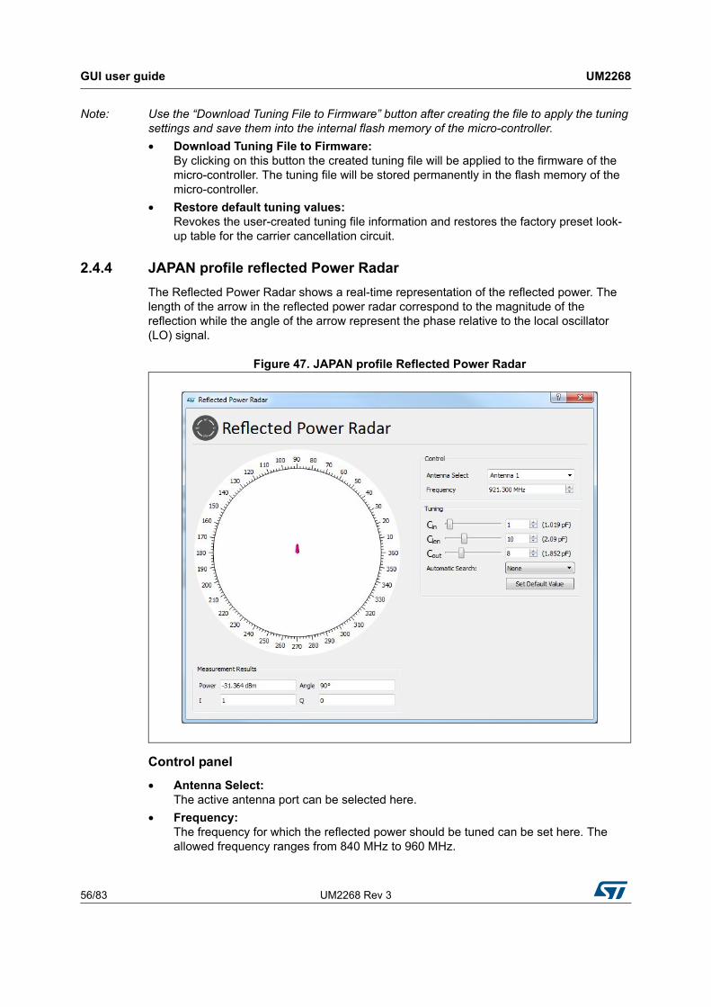
2.4.4 JAPAN profile reflected Power Radar
The Reflected Power Radar shows a real-time representation of the reflected power. The length of the arrow in the reflected power radar correspond to the magnitude of the reflection while the angle of the arrow represent the phase relative to the local oscillator (LO) signal.
Figure 47. JAPAN profile Reflected Power Radar
Control panel
• Antenna Select: The active antenna port can be selected here.
• Frequency: The frequency for which the reflected power should be tuned can be set here. The allowed frequency ranges from 840 MHz to 960 MHz.

UM2268 Rev 3 57/83
UM2268 GUI user guide
81
Tuning panel
• Cin: This slider changes the capacitance value of the input shunt capacitor of the carrier cancellation circuit.
• Clen: This slider changes the capacitance value of the series capacitor of the carrier cancellation circuit.
• Cout: This slider changes the capacitance value of the output shunt capacitor of the carrier cancellation circuit.
• Autom. Search: This pull-down menu defines which algorithm will be used to search for the reflected power minimum.
• Climb Current [fast]: Searches for a reflected power minimum starting from the current configuration of the carrier cancellation circuit. To find the minimum the variable capacitors are adjusted and a measurement of the resulting reflected power is initiated. The automatic algorithm stops when capacitor configurations are found that result to the lowest reflected power. The best capacitor configurations are automatically applied. Changing the three capacitor values manually defines a new starting point for the search.
• Climb Points [slow]: Performs multiple reflected power minimum searches starting from different pre-defined capacitor configurations. The automatic algorithm stops when all individual searches are completed. The reflected power measurement results of all individual searches are compared against each other and the capacitor configurations for the overall minimum reflected power is applied.
• Set Default Value: Reverts the configuration of all variable capacitors to their default value for a default frequency. If the current active frequency is not a default frequency the capacitor values are set to step 15 (1.495 pF).
Measurement Results panel
• Power: Shows the reflected power measurement result in a numeric form. The reflected power measurement is performed by ST25RU3993.
• Angle: Shows the phase of the reflected power relative to the local oscillator signal.
• I: ADC results for the in-phase component of the reflected power measured by ST25RU3993
• Q: ADC results for the quadrature component of the reflected power measured by ST25RU3993
GUI user guide UM2268
58/83 UM2268 Rev 3
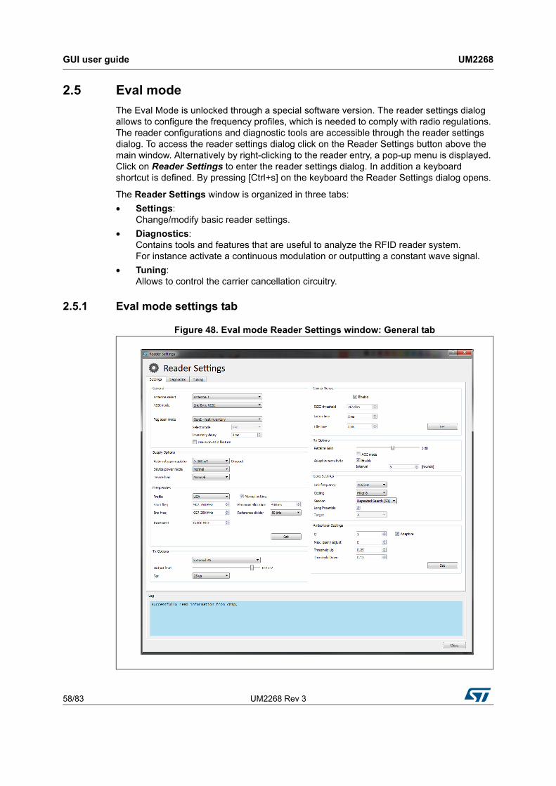
2.5 Eval mode
The Eval Mode is unlocked through a special software version. The reader settings dialog allows to configure the frequency profiles, which is needed to comply with radio regulations. The reader configurations and diagnostic tools are accessible through the reader settings dialog. To access the reader settings dialog click on the Reader Settings button above the main window. Alternatively by right-clicking to the reader entry, a pop-up menu is displayed. Click on Reader Settings to enter the reader settings dialog. In addition a keyboard shortcut is defined. By pressing [Ctrl+s] on the keyboard the Reader Settings dialog opens.
The Reader Settings window is organized in three tabs:
• Settings: Change/modify basic reader settings.
• Diagnostics: Contains tools and features that are useful to analyze the RFID reader system. For instance activate a continuous modulation or outputting a constant wave signal.
• Tuning: Allows to control the carrier cancellation circuitry.
2.5.1 Eval mode settings tab
Figure 48. Eval mode Reader Settings window: General tab

UM2268 Rev 3 59/83
UM2268 GUI user guide
81
General panel
• Antenna Select: Select either Antenna 1 or Antenna 2 as the active antenna port depending on the antenna configuration. If the antenna is selected an entry field appears below to define the number of inventory rounds after which the active antenna port should be switched. The maximum number that can be entered is 99 rounds.
• RSSI mode: Defines when the RSSI of the tag is measured.
• Tag Scan Mode: Defines the next communication steps once the tag has replied with its EPC.
– Gen2 - Fast inventory: The Tag sends EPC number and reverts to READY state.
– Gen2 - Normal inventory: The Tag sends HANDLE and reverts to READY state. Gen2 - Normal Inventory with TID: Same as Normal Inventory with an additional readout of the TID memory. If this option is selected, a pull-down menu named “Select mode” appears, which allows to select the information (EPC, TID or both).
– ISO 6B: Scan for a ISO 6B Tag
• Inventory Delay: By changing the Inventory Delay [ms], an additional wait time is inserted between two consecutive inventory rounds. The maximum value is 20000 [ms].
• AutoAck feature checkbox: Enables the autoACK feature for tag inventories that automates sending the ACK command or the ACK and ReqRN command according to the Gen2 protocol. Depending on the tag scan mode selection above, AutoACK and Gen2 - fast inventory will send the ACK command after the RN16 and RN16 automatically while AUTOACK and Gen2 - normal inventory will send the ACK command after the RN16 and also the ReqRN command after the EPC response of the tag.
Supply options panel
In order to measure the power consumption of the ST25RU3993 you can change the device power mode and settings here.
• Auto voltage regulator: Internal voltage regulators maintain a certain drop-out voltage even with decreased supply/battery voltage.
• Device power mode: Allows to bring the reader IC into various supply power states.
• Device Bias Allows to change the bias setting for the entire IC resulting in less current consumption at the expense of performance.

GUI user guide UM2268
60/83 UM2268 Rev 3
Tx Options panel
• External/Internal PA: This allows to switch between external or internal power amplifiers.
• Output level: The Output level slider changes the output power for the 0-dBm and the internal PA output (register 0x15, bits [4:0]). The output power may be changed by nominal 1 dB per step.
• TARI: Gen2 transmission setting. Changes the TX-Zero lengh to:
– 6.25 µs
– 12.5 µs
– 25 µs
Carrier Sense panel If enabled the reader will sense if the next transmit frequency channel is free or already occupied by another reader.
• RSSI threshold: If the signal strength of the sensed carrier is below this threshold, the slot is considered free, and therefore will be used by the reader. The RSSI threshold can be entered from -40 dBm down to -80 dBm.
• Listen time: Carrier Sense duration. During this time the RSSI is measured repeatedly. The maximum value is then checked for threshold crossing.
• Idle time: Wait time between transmit frequency channel switch and performing Carrier Sense.
Rx Options panel
• Receive Gain: The receive gain slider adjusts the receive gain and/or receive attenuation of the reader. The slider affects register 0x0A.
• AGC Mode: Enables/Disables the automatic gain control feature of the ST25RU3993.
• Adaptive Sensitivity Section: This section allows to enable/disable adaptive receive gain/attenuation change. If enabled the receive gain will be automatically increased if no tags are found and decreased, if the tag RSSI is high.
• Interval: Defines after which number of inventory rounds the receive gain/attenuation is re-adjusted. The maximum value that can be entered is 99 rounds.
UM2268 Rev 3 61/83
UM2268 GUI user guide
81
Gen2 Settings panel
• Link frequency: Changes the backscatter link frequency to:
– 40 kHz
– 160 kHz
– 213 kHz
– 256 kHz
– 320 kHz
– 640 kHz
• Coding: Changes the coding to:
– FM0
– Miller 2
– Miller 4
– Miller 8
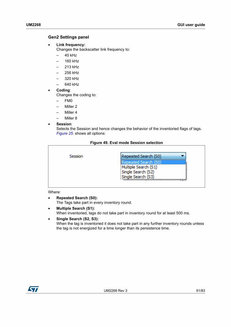
• Session: Selects the Session and hence changes the behavior of the inventoried flags of tags. Figure 25. shows all options:
Figure 49. Eval mode Session selection
Where:
• Repeated Search (S0): The Tags take part in every inventory round.
• Multiple Search (S1): When inventoried, tags do not take part in inventory round for at least 500 ms.
• Single Search (S2, S3): When the tag is inventoried it does not take part in any further inventory rounds unless the tag is not energized for a time longer than its persistence time.
GUI user guide UM2268
62/83 UM2268 Rev 3
Anti-collision settings panel
• Q: Defines the initial number of available anti-collision slots according to Gen2 protocol specification. The maximum value that can be entered is 15. if adaptive is activated the reader is adjusting the Q value according to the present tags in the read zone. The reader attempts to minimize the number of empty slots and the number of collisions (pre-amble errors).
• Max. query adjust: Maximum rounds (QueryRep) which are additionally performed. An inventory round is started with an Query command and collects tags in 2^Q slots. If collisions occur, some tags will not be inventoried. The inventory round will be extended with the number of defined QueryAdjust commands. Tags which have not been inventoried yet will participate in additional rounds with Q adjusted.
• Thresholds Up: The adjustment of Q is dependent on the occurred collisions. Q will be increased if the number of collisions is greater or equal than the number of slots multiplied by the defined Threshold Up value.
• Threshold down: The adjustment of Q is dependent on the occurred collisions. Q will be decreased if the number of collisions is lower than the number of slots multiplied by the defined Threshold Down value.
Note: If none of the above threshold criteria are met Q will remain unchanged.
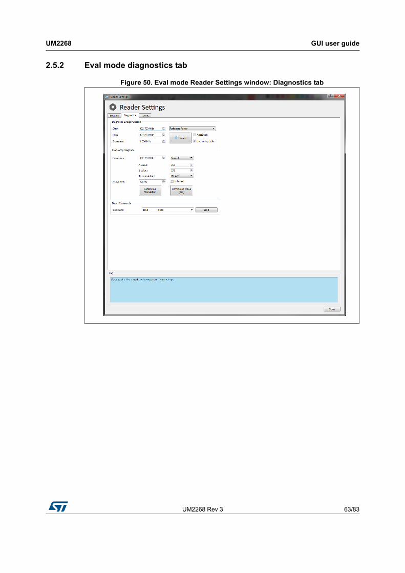
UM2268 Rev 3 63/83
UM2268 GUI user guide
81
2.5.2 Eval mode diagnostics tab
Figure 50. Eval mode Reader Settings window: Diagnostics tab
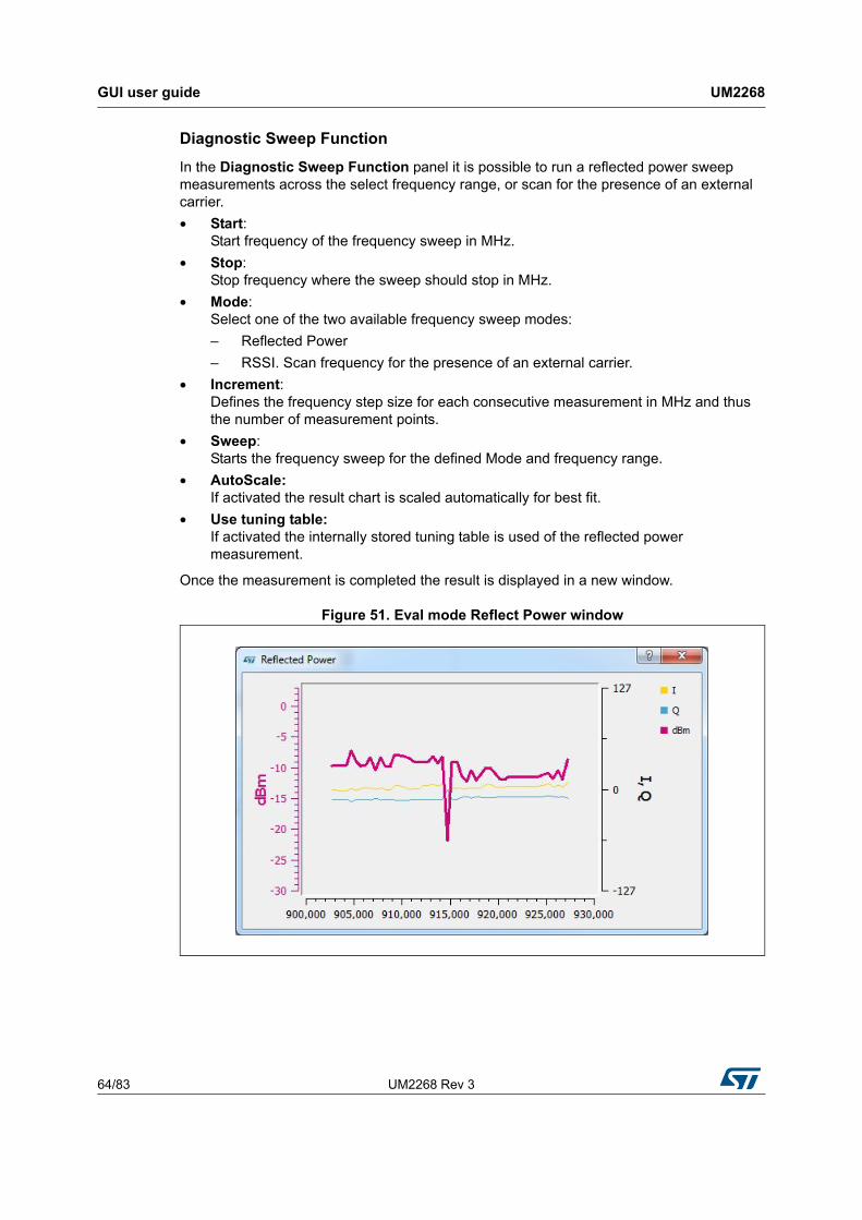
GUI user guide UM2268
64/83 UM2268 Rev 3
Diagnostic Sweep Function
In the Diagnostic Sweep Function panel it is possible to run a reflected power sweep measurements across the select frequency range, or scan for the presence of an external carrier.
• Start: Start frequency of the frequency sweep in MHz.
• Stop: Stop frequency where the sweep should stop in MHz.
• Mode: Select one of the two available frequency sweep modes:
– Reflected Power
– RSSI. Scan frequency for the presence of an external carrier.
• Increment: Defines the frequency step size for each consecutive measurement in MHz and thus the number of measurement points.
• Sweep: Starts the frequency sweep for the defined Mode and frequency range.
• AutoScale: If activated the result chart is scaled automatically for best fit.
• Use tuning table: If activated the internally stored tuning table is used of the reflected power measurement.
Once the measurement is completed the result is displayed in a new window.
Figure 51. Eval mode Reflect Power window

UM2268 Rev 3 65/83
UM2268 GUI user guide
81
Frequency Diagnosis panel
• Frequency: Defines the frequency at which the CW or modulated carrier is output.
• A value: Display the decimal value of the PLL A register
• B value: Displays the decimal value of the PLL B register
• TX modulation: Defines the current modulation type
• Active time: Defines the time the TX output is ON
• Continuous Wave (CW): Generates a continuous carrier wave at the selected frequency.
• Continuous Modulation: If set to normal mode the reader continuously transmits a NAK command at the specified frequency for a given period of time.
– Pseudo Random: If this option is selected the reader outputs the carrier modulated by pseudo random data.
– ETSI Test Mode: With this option the reader outputs the test signal defined in EN 302 208.
Direct Commands panel
• Direct Command: A selection menu from which direct commands may be selected and transmitted.
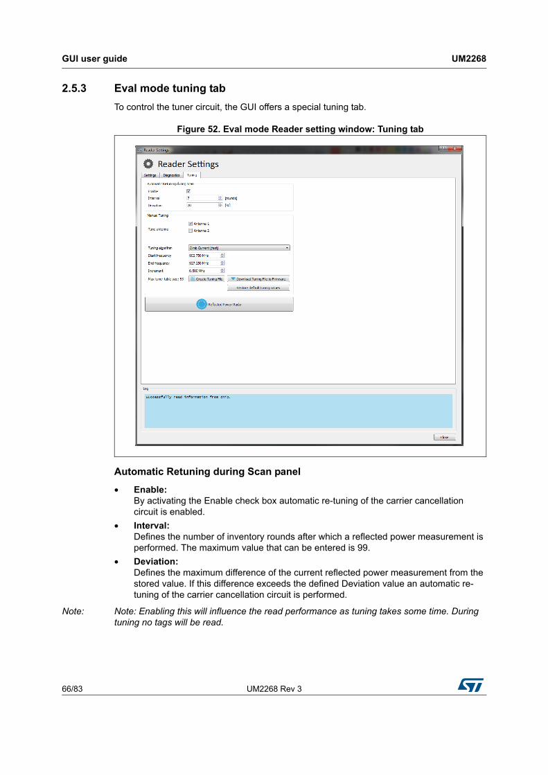
GUI user guide UM2268
66/83 UM2268 Rev 3
2.5.3 Eval mode tuning tab
To control the tuner circuit, the GUI offers a special tuning tab.
Figure 52. Eval mode Reader setting window: Tuning tab
Automatic Retuning during Scan panel
• Enable: By activating the Enable check box automatic re-tuning of the carrier cancellation circuit is enabled.
• Interval: Defines the number of inventory rounds after which a reflected power measurement is performed. The maximum value that can be entered is 99.
• Deviation: Defines the maximum difference of the current reflected power measurement from the stored value. If this difference exceeds the defined Deviation value an automatic re-tuning of the carrier cancellation circuit is performed.
Note: Note: Enabling this will influence the read performance as tuning takes some time. During tuning no tags will be read.
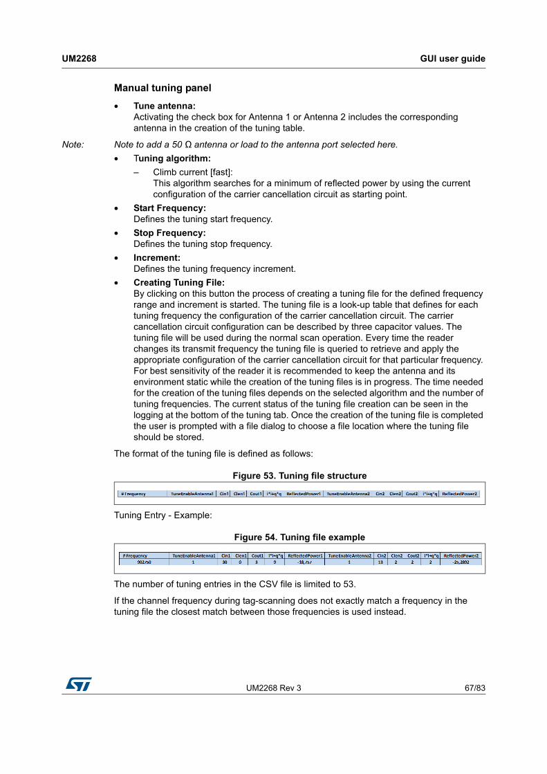
UM2268 Rev 3 67/83
UM2268 GUI user guide
81
Manual tuning panel
• Tune antenna: Activating the check box for Antenna 1 or Antenna 2 includes the corresponding antenna in the creation of the tuning table.
Note: Note to add a 50 Ω antenna or load to the antenna port selected here.
• Tuning algorithm:
– Climb current [fast]: This algorithm searches for a minimum of reflected power by using the current configuration of the carrier cancellation circuit as starting point.
• Start Frequency: Defines the tuning start frequency.
• Stop Frequency: Defines the tuning stop frequency.
• Increment: Defines the tuning frequency increment.
• Creating Tuning File: By clicking on this button the process of creating a tuning file for the defined frequency range and increment is started. The tuning file is a look-up table that defines for each tuning frequency the configuration of the carrier cancellation circuit. The carrier cancellation circuit configuration can be described by three capacitor values. The tuning file will be used during the normal scan operation. Every time the reader changes its transmit frequency the tuning file is queried to retrieve and apply the appropriate configuration of the carrier cancellation circuit for that particular frequency. For best sensitivity of the reader it is recommended to keep the antenna and its environment static while the creation of the tuning files is in progress. The time needed for the creation of the tuning files depends on the selected algorithm and the number of tuning frequencies. The current status of the tuning file creation can be seen in the logging at the bottom of the tuning tab. Once the creation of the tuning file is completed the user is prompted with a file dialog to choose a file location where the tuning file should be stored.
The format of the tuning file is defined as follows:
Figure 53. Tuning file structure
Tuning Entry - Example:
Figure 54. Tuning file example
The number of tuning entries in the CSV file is limited to 53.
If the channel frequency during tag-scanning does not exactly match a frequency in the tuning file the closest match between those frequencies is used instead.
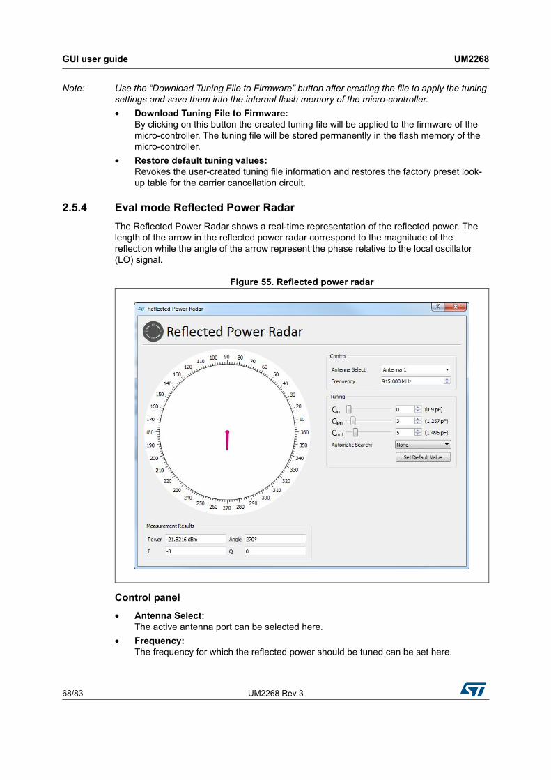
GUI user guide UM2268
68/83 UM2268 Rev 3
Note: Use the “Download Tuning File to Firmware” button after creating the file to apply the tuning settings and save them into the internal flash memory of the micro-controller.
• Download Tuning File to Firmware: By clicking on this button the created tuning file will be applied to the firmware of the micro-controller. The tuning file will be stored permanently in the flash memory of the micro-controller.
• Restore default tuning values: Revokes the user-created tuning file information and restores the factory preset look-up table for the carrier cancellation circuit.
2.5.4 Eval mode Reflected Power Radar
The Reflected Power Radar shows a real-time representation of the reflected power. The length of the arrow in the reflected power radar correspond to the magnitude of the reflection while the angle of the arrow represent the phase relative to the local oscillator (LO) signal.
Figure 55. Reflected power radar
Control panel
• Antenna Select: The active antenna port can be selected here.
• Frequency: The frequency for which the reflected power should be tuned can be set here.
UM2268 Rev 3 69/83
UM2268 GUI user guide
81
Tuning panel
• Cin: This slider changes the capacitance value of the input shunt capacitor of the carrier cancellation circuit.
• Clen: This slider changes the capacitance value of the series capacitor of the carrier cancellation circuit.
• Cout: This slider changes the capacitance value of the output shunt capacitor of the carrier cancellation circuit.
• Autom. Search: This pull-down menu defines which algorithm will be used to search for the reflected power minimum.
• Climb Current [fast]: Searches for a reflected power minimum starting from the current configuration of the carrier cancellation circuit. To find the minimum the variable capacitors are adjusted and a measurement of the resulting reflected power is initiated. The automatic algorithm stops when capacitor configurations are found that result to the lowest reflected power. The best capacitor configurations are automatically applied. Changing the three capacitor values manually defines a new starting point for the search.
• Set Default Value: Reverts the configuration of all variable capacitors to their default value for a default frequency. If the current active frequency is not a default frequency the capacitor values are set to step 15 (1.495 pF).
Measurement Results panel
• Power: Shows the reflected power measurement result in a numeric form. The reflected power measurement is performed by ST25RU3993.
• Angle: Shows the phase of the reflected power relative to the local oscillator signal.
• I: ADC results for the in-phase component of the reflected power measured by ST25RU3993
• Q: ADC results for the quadrature component of the reflected power measured by ST25RU3993
GUI user guide UM2268
70/83 UM2268 Rev 3
2.6 Register map
The purpose of the register map is to provide access to all registers in order to observe and if operating in the Eval mode change register settings. By moving the mouse pointer over a bit cell a tool-tip text is displayed providing detailed information about the actual bit and its function. The register map also provides means to modify the contents of the write-able registers. By clicking on a bit cell the value of the actual bit can be changed. Alternatively a register may be modified by entering a new hexadecimal value in the right-most Value column. Note that it is not recommended to alter any registers through the register map while the reader is scanning or any other automatic procedure such as tuning file creation is on going.
The register map can be accessed by clicking on the Register Map button above the main window. Alternatively by a right-click on the reader entry a pop-up menu appears form which the register map can be accessed. In addition a keyboard shortcut is defined as well. By pressing [Ctrl+m] the register map opens as well.
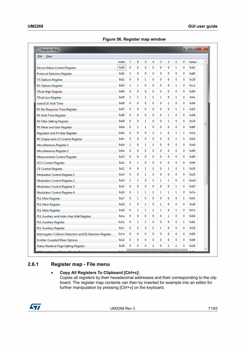
UM2268 Rev 3 71/83
UM2268 GUI user guide
81
Figure 56. Register map window
2.6.1 Register map - File menu
• Copy All Registers To Clipboard [Ctrl+c]: Copies all registers by their hexadecimal addresses and their corresponding to the clip board. The register map contents can then by inserted for example into an editor for further manipulation by pressing [Ctrl+v] on the keyboard.
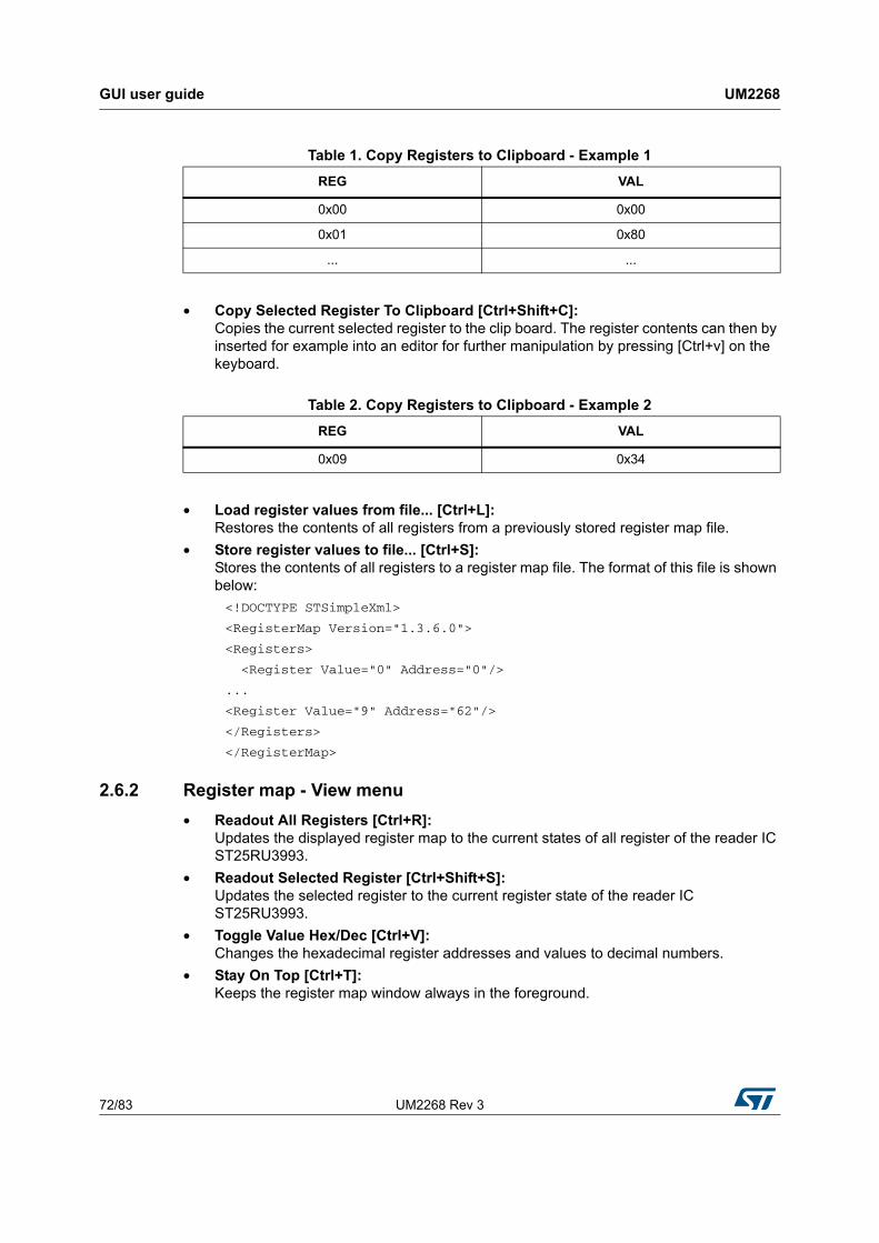
GUI user guide UM2268
72/83 UM2268 Rev 3
• Copy Selected Register To Clipboard [Ctrl+Shift+C]: Copies the current selected register to the clip board. The register contents can then by inserted for example into an editor for further manipulation by pressing [Ctrl+v] on the keyboard.
• Load register values from file... [Ctrl+L]: Restores the contents of all registers from a previously stored register map file.
• Store register values to file... [Ctrl+S]: Stores the contents of all registers to a register map file. The format of this file is shown below:
<!DOCTYPE STSimpleXml>
<RegisterMap Version="1.3.6.0">
<Registers>
<Register Value="0" Address="0"/>
...
<Register Value="9" Address="62"/>
</Registers>
</RegisterMap>
2.6.2 Register map - View menu
• Readout All Registers [Ctrl+R]: Updates the displayed register map to the current states of all register of the reader IC ST25RU3993.
• Readout Selected Register [Ctrl+Shift+S]: Updates the selected register to the current register state of the reader IC ST25RU3993.
• Toggle Value Hex/Dec [Ctrl+V]: Changes the hexadecimal register addresses and values to decimal numbers.
• Stay On Top [Ctrl+T]: Keeps the register map window always in the foreground.
Table 1. Copy Registers to Clipboard - Example 1
REG VAL
0x00 0x00
0x01 0x80
... ...
Table 2. Copy Registers to Clipboard - Example 2
REG VAL
0x09 0x34
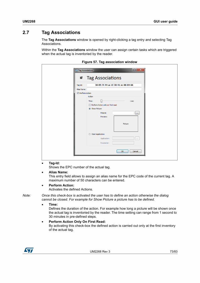
UM2268 Rev 3 73/83
UM2268 GUI user guide
81
2.7 Tag Associations
The Tag Associations window is opened by right-clicking a tag entry and selecting Tag Associations.
Within the Tag Associations window the user can assign certain tasks which are triggered when the actual tag is inventoried by the reader.
Figure 57. Tag association window
• Tag-Id: Shows the EPC number of the actual tag.
• Alias Name: This entry field allows to assign an alias name for the EPC code of the current tag. A maximum number of 50 characters can be entered.
• Perform Action: Activates the defined Actions.
Note: Once this check-box is activated the user has to define an action otherwise the dialog cannot be closed. For example for Show Picture a picture has to be defined.
• Time: Defines the duration of the action. For example how long a picture will be shown once the actual tag is inventoried by the reader. The time setting can range from 1 second to 30 minutes in pre-defined steps.
• Perform Action Only On First Read: By activating this check-box the defined action is carried out only at the first inventory of the actual tag.

GUI user guide UM2268
74/83 UM2268 Rev 3
• Show Picture: If Show Picture is selected a picture is shown when the actual tag is inventoried by the reader.
• Picture: In the entry field the file location of the picture can be entered. Alternatively a select file dialog can be opened by pressing on the button next to the entry field.
• Preview: Shows a thumbnail preview of the select picture.
• Start Application: If Start Application is selected an application can be started when the actual tag is inventoried by the reader.
• Application: In the entry field the file location of the executable of the application can be entered. Alternatively a select file dialog can be opened by pressing on the button next to the entry field.
• Parameter: Enter parameters needed for the application here.
To activate the assigned tag action, click on Handle Actions button.
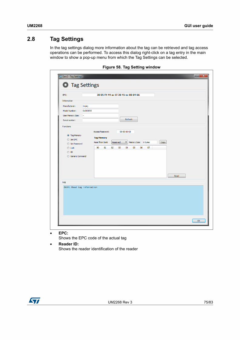
UM2268 Rev 3 75/83
UM2268 GUI user guide
81
2.8 Tag Settings
In the tag settings dialog more information about the tag can be retrieved and tag access operations can be performed. To access this dialog right-click on a tag entry in the main window to show a pop-up menu from which the Tag Settings can be selected.
Figure 58. Tag Setting window
• EPC: Shows the EPC code of the actual tag
• Reader ID: Shows the reader identification of the reader
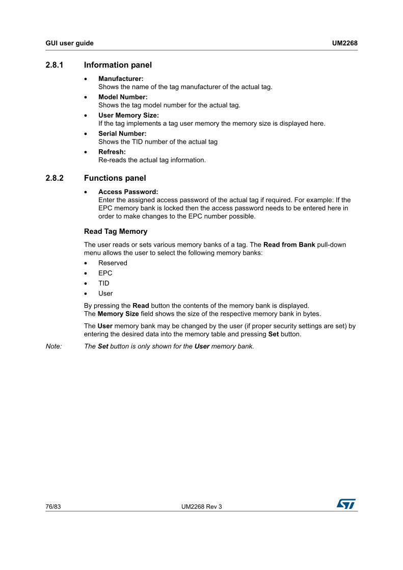
GUI user guide UM2268
76/83 UM2268 Rev 3
2.8.1 Information panel
• Manufacturer: Shows the name of the tag manufacturer of the actual tag.
• Model Number: Shows the tag model number for the actual tag.
• User Memory Size: If the tag implements a tag user memory the memory size is displayed here.
• Serial Number: Shows the TID number of the actual tag
• Refresh: Re-reads the actual tag information.
2.8.2 Functions panel
• Access Password: Enter the assigned access password of the actual tag if required. For example: If the EPC memory bank is locked then the access password needs to be entered here in order to make changes to the EPC number possible.
Read Tag Memory
The user reads or sets various memory banks of a tag. The Read from Bank pull-down menu allows the user to select the following memory banks:
• Reserved
• EPC
• TID
• User
By pressing the Read button the contents of the memory bank is displayed. The Memory Size field shows the size of the respective memory bank in bytes.
The User memory bank may be changed by the user (if proper security settings are set) by entering the desired data into the memory table and pressing Set button.
Note: The Set button is only shown for the User memory bank.
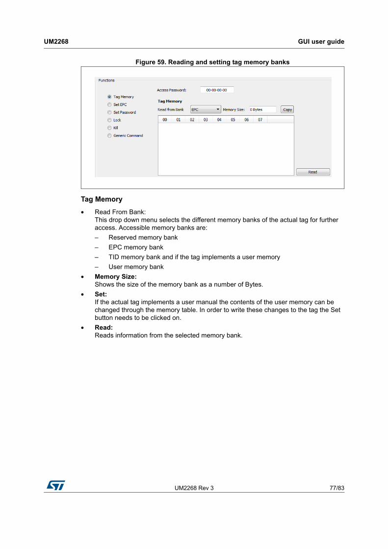
UM2268 Rev 3 77/83
UM2268 GUI user guide
81
Figure 59. Reading and setting tag memory banks
Tag Memory
• Read From Bank: This drop down menu selects the different memory banks of the actual tag for further access. Accessible memory banks are:
– Reserved memory bank
– EPC memory bank
– TID memory bank and if the tag implements a user memory
– User memory bank
• Memory Size: Shows the size of the memory bank as a number of Bytes.
• Set: If the actual tag implements a user manual the contents of the user memory can be changed through the memory table. In order to write these changes to the tag the Set button needs to be clicked on.
• Read: Reads information from the selected memory bank.
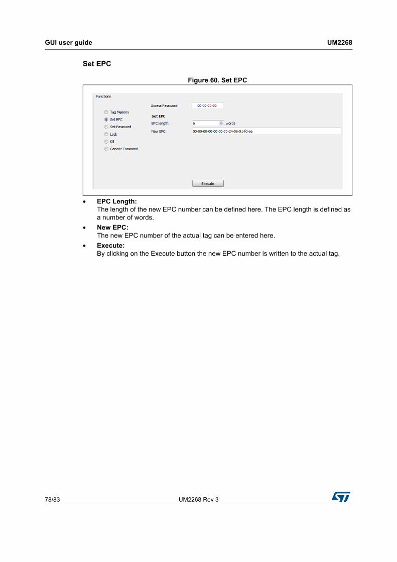
GUI user guide UM2268
78/83 UM2268 Rev 3
Set EPC
Figure 60. Set EPC
• EPC Length: The length of the new EPC number can be defined here. The EPC length is defined as a number of words.
• New EPC: The new EPC number of the actual tag can be entered here.
• Execute: By clicking on the Execute button the new EPC number is written to the actual tag.
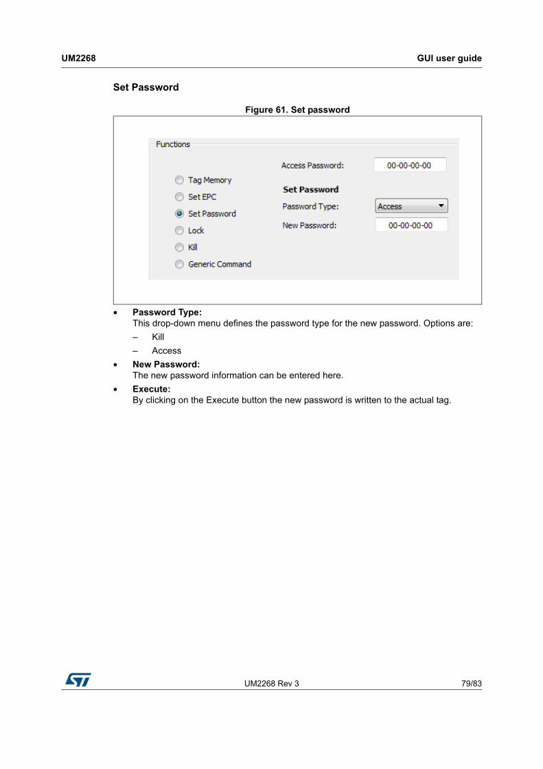
UM2268 Rev 3 79/83
UM2268 GUI user guide
81
Set Password
Figure 61. Set password
• Password Type: This drop-down menu defines the password type for the new password. Options are:
– Kill
– Access
• New Password: The new password information can be entered here.
• Execute: By clicking on the Execute button the new password is written to the actual tag.
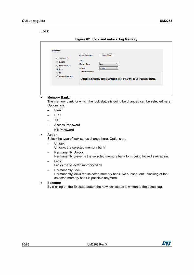
GUI user guide UM2268
80/83 UM2268 Rev 3
Lock
Figure 62. Lock and unlock Tag Memory
• Memory Bank: The memory bank for which the lock status is going be changed can be selected here. Options are:
– User
– EPC
– TID
– Access Password
– Kill Password
• Action: Select the type of lock status change here. Options are:
– Unlock: Unlocks the selected memory bank
– Permanently Unlock: Permanently prevents the selected memory bank form being locked ever again.
– Lock: Locks the selected memory bank
– Permanently Lock: Permanently locks the selected memory bank. No subsequent unlocking of the selected memory bank is possible anymore.
• Execute: By clicking on the Execute button the new lock status is written to the actual tag.
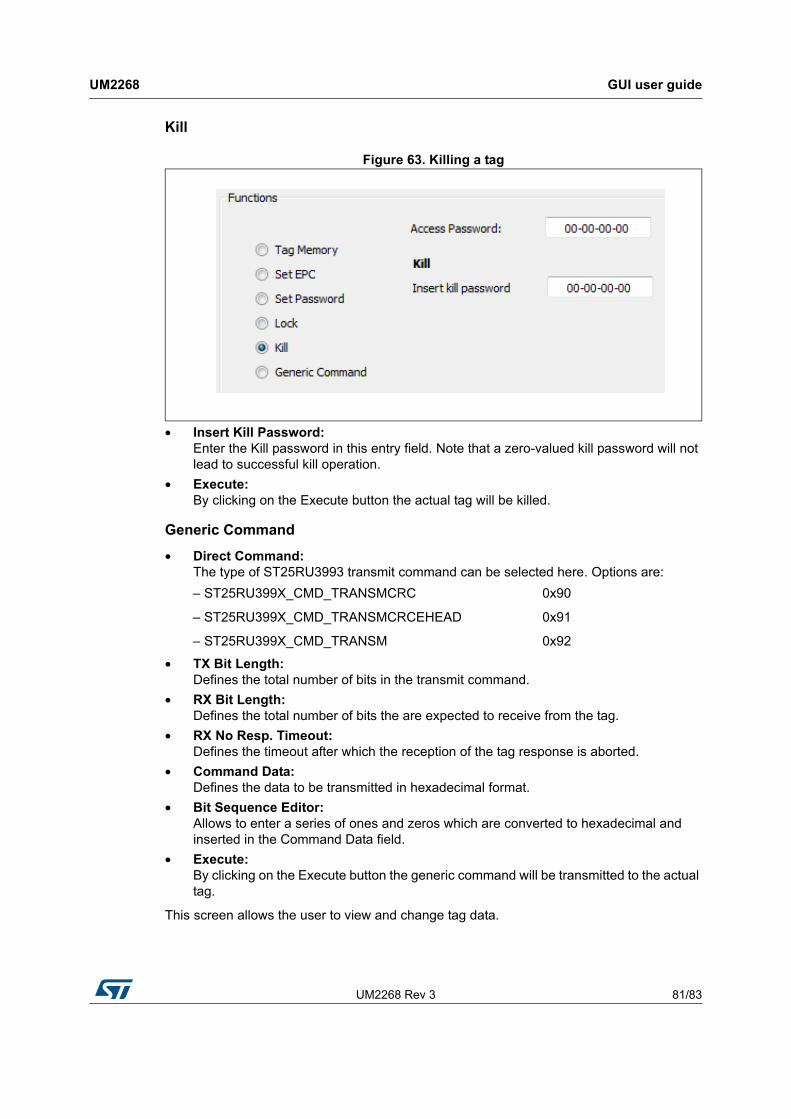
UM2268 Rev 3 81/83
UM2268 GUI user guide
81
Kill
Figure 63. Killing a tag
• Insert Kill Password: Enter the Kill password in this entry field. Note that a zero-valued kill password will not lead to successful kill operation.
• Execute: By clicking on the Execute button the actual tag will be killed.
Generic Command
• Direct Command: The type of ST25RU3993 transmit command can be selected here. Options are:
• TX Bit Length: Defines the total number of bits in the transmit command.
• RX Bit Length: Defines the total number of bits the are expected to receive from the tag.
• RX No Resp. Timeout: Defines the timeout after which the reception of the tag response is aborted.
• Command Data: Defines the data to be transmitted in hexadecimal format.
• Bit Sequence Editor: Allows to enter a series of ones and zeros which are converted to hexadecimal and inserted in the Command Data field.
• Execute: By clicking on the Execute button the generic command will be transmitted to the actual tag.
This screen allows the user to view and change tag data.
– ST25RU399X_CMD_TRANSMCRC 0x90
– ST25RU399X_CMD_TRANSMCRCEHEAD 0x91
– ST25RU399X_CMD_TRANSM 0x92
Revision history UM2268
82/83 UM2268 Rev 3
3 Revision history
Table 3. Document revision history
Date Revision Changes
27-Mar-2018 1 Initial release.
12-Apr-2018 2Updated:
– Introduction
29-Nov-2018 3
Added:
– Section 2.3: Reader setting - USA profile
– Section 2.2.1: EU profile settings tab
– Section 2.2.2: Eu profile diagnostics tab
– Section 2.2.3: EU profile: Tuning tab
– Section 2.2.4: Reflected Power Radar
– Section 2.4: Reader settings - JAPAN profile
– Section 2.3.1: USA profile settings tab
– Section 2.3.2: USA profile diagnostics tab
– Section 2.3.3: USA profile tuning tab
– Section 2.3.4: USA profile reflected Power Radar
– Section 2.5: Eval mode
– Section 2.5.1: Eval mode settings tab
– Section 2.5.2: Eval mode diagnostics tab
– Section 2.5.3: Eval mode tuning tab
– Section 2.5.4: Eval mode Reflected Power Radar
Updated:
– Introduction
– Figure 1: Hardware configuration of evaluation board
– Figure 27: EU profile Reflect Power window
– Section 2.2: Reader settings - EU profile
– Section 2.3: Reader setting - USA profile
– Section 2.4: Reader settings - JAPAN profile

UM2268 Rev 3 83/83
UM2268
83
IMPORTANT NOTICE – PLEASE READ CAREFULLY
STMicroelectronics NV and its subsidiaries (“ST”) reserve the right to make changes, corrections, enhancements, modifications, and improvements to ST products and/or to this document at any time without notice. Purchasers should obtain the latest relevant information on ST products before placing orders. ST products are sold pursuant to ST’s terms and conditions of sale in place at the time of order acknowledgement.
Purchasers are solely responsible for the choice, selection, and use of ST products and ST assumes no liability for application assistance or the design of Purchasers’ products.
No license, express or implied, to any intellectual property right is granted by ST herein.
Resale of ST products with provisions different from the information set forth herein shall void any warranty granted by ST for such product.
ST and the ST logo are trademarks of ST. All other product or service names are the property of their respective owners.
Information in this document supersedes and replaces information previously supplied in any prior versions of this document.
© 2018 STMicroelectronics – All rights reserved