Embed Size (px)
Citation preview
IT Department
Revised April 2014 1 Structured Cabling Standrds-Version 5.5
St Johns County School District
Voice and Data
Structured Cabling Standards
IT Department
Revised April 2014 2 Structured Cabling Standrds-Version 5.5
Table of Contents
Article 1. General Information ...................................................................................................... 5
Article 2. Telecommunications Conduit Systems ......................................................................... 6
Article 3. Telecommunications Rooms ......................................................................................... 7
Article 4. Support Systems .......................................................................................................... 10
Article 5. Electrical Power .......................................................................................................... 10
Article 6. Telecommunications Systems Grounding/Bonding .................................................... 11
Article 7. Environmental Requirements for Telecommunications Rooms ................................. 11
Article 8. Horizontal Structured Cabling .................................................................................... 12
Article 9. Backbone Cabling and Installation ............................................................................. 16
Article 10. Wireless Voice and Data Network Design Requirements ....................................... 18
Article 11. Labeling and Administration .................................................................................. 19
Article 12. Testing and Documentation ..................................................................................... 22
Article 13. Relocatable Classroom Systems Specs. .................................................................. 23
Article 14. Classroom Audio/Visual Technology ..................................................................... 31
Article 15. Applicable Industry Standards ................................................................................ 42
IT Department
Revised April 2014 3 Structured Cabling Standrds-Version 5.5
Document Updates:
Section/
Article Summary of Changes Changes by
Change
Date
Document
Version #
11.02 Added test results submittal email Justin Forfar 10 Oct 06 V4.0
All Version 4.2 Released Justin Forfar 11 Oct 06 V4.2
All Changed from Cat5E to Cat6 spec Justin Forfar 8 Nov 06 V4.2
9.01(c) Addressed space issues brought up by
engineers
Justin Forfar 14 Nov 06 V4.2
8 Added Cat6 performance spec Justin Forfar 14 Nov 06 V4.2
3 Added cable mgmt and cable tray
reqs
Justin Forfar 27 Feb 07 V4.21
10 Added wireless network spec article Justin Forfar 19 Nov 07 V4.22
3.01(b) Added requirement for ER and TR
detail drawings
Justin Forfar 10 Dec 07 V4.22
5.02(b) Removed requirement isolated ground Justin Forfar 24 Sep 08 V4.22
9.02(e) Removed fiber jumper provision Justin Forfar 8 Oct 08 V4.22
14 New Chris Petrello 10 Oct 08 V4.22
All Format, add TOC Bruce Patrou 14 Oct 08 V4.22.3
All Released Version 4.22.4 Justin Forfar 15 Oct 08 V4.22.4
14.01(b) Clarified requirement for master
volume control via teacher control
wallplate
Justin Forfar 6 Jan 10 V4.3
14 Added Model Classroom AV
inspection requirement
Justin Forfar 6 Jan 10 V4.3
14.01(l) Clarification of AV shelf mounting
height and location
Justin Forfar 6 Jan 10 V4.3
14.01(e) Added model number for Wall Plate 1 Justin Forfar 6 Jan 10 V4.3
All Released Version 4.3 Justin Forfar 6 Jan 10 V4.3
11 Clarified labeling and install
requirements for WAP WAOs, MLC
WAOs
Justin Forfar 10 Mar 11 V5.0
8.05 Clarified TR side requirements for
modular jack color codes
Justin Forfar 10 Mar 11 V5.0
8.01 Clarified horizontal data cabling
options
Justin Forfar 10 Mar 11 V5.0
9.02 Updated Fiber Optic cabling
specifications
Justin Forfar 22 Mar 11 V5.0
IT Department
Revised April 2014 4 Structured Cabling Standrds-Version 5.5
14 Complete rewrite to include Extron
PoleVault Standard including new
AVerMedia Tuners, Clarified
projection screen size and throw
distance
Justin Forfar 30 Mar 11 V5.0
13 General update of portables section-
new pedestal types, added detail
drawings for portables.
Justin Forfar 30 Mar 11 V5.0
13.01 Added diagram for standard
relocatable classroom data pedestal
buildout.
Justin Forfar 3 May 12 V5.5
8.04 Edited section title to include
faceplates as well as patch panels
Justin Forfar 3 May 12 V5.5
10.0 Revised wireless standards to include
AP mfr, two cables per location
Justin Forfar 3 May 12 V5.5
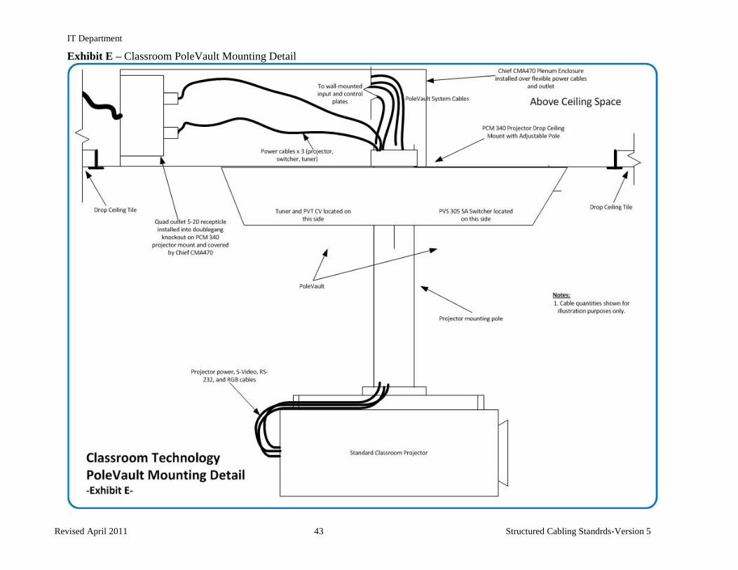
14.03 Added Chief CMA470 Plenum
enclosure to PoleVault System parts
list
Justin Forfar 3 May 12 V5.5
14 Edited Exhibit E to reflect use of
Chief CMA470 Plenum enclosure
Justin Forfar 3 May 12 V5.5
IT Department
Revised April 2014 5 Structured Cabling Standrds-Version 5.5
Article 1. General Information
Section 1.01 Statement of Purpose
The purpose of this document is to enumerate the standards and practices to be followed when designing
structured cabling systems for the St Johns County School District. Each section of this document outlines: 1)
a specific part of a structured cabling system or manner in which a product or technology should be installed
or 2) a specific product line or product that shall be used for a certain part of an installation. This document is
to be used in conjunction with all applicable industry standards and codes to provide the St Johns County
School District with a flexible, scalable, easily managed, properly documented structured cabling network.
Section 1.02 General Voice and Data Network Service Requirements
(a) All areas of a building shall be equipped with voice and data network access during the design
phase. These areas include but are not limited to:
(i) Classroom and learning spaces including teacher planning rooms
(ii) Administrative offices including conference rooms and work rooms
(iii) Storage spaces including book storage and central receiving
(iv) Media/Library spaces including all work rooms, professional work spaces, and group project
areas
(v) Auditorium spaces including ticket windows, concessions, dressing areas, and control booth
(vi) Gym spaces including all coaches offices, breakout rooms, trainer’s offices, and nurse’s offices
(vii) Athletic fields including all field houses and press boxes
Section 1.03 Terminology
(a) MTR – Main telecommunications room that houses all core electronics and telephone service
provider demark
(b) TR –Telecommunications room located throughout site as cable length requires
(c) Work Area Outlet (WAO) - a location within a classroom or office that offers a connection or
group of connections to the structured cabling network.
(d) TBB- Telecommunications Bus Bar
(e) WAP- Wireless access point
(f) EC- Equipment cabinet – may house active or passive equipment
IT Department
Revised April 2014 6 Structured Cabling Standrds-Version 5.5
Article 2. Telecommunications Conduit Systems
Section 2.01 General Standards for Conduit
(a) All voice or data conduits installed between an MTR or TR and another MTR/TR shall be filled to
capacity with 1” nominal inside diameter corrugated innerduct.
(b) A ½” 1200lb rated pull tape shall be installed in each innerduct and secured at each end.
(c) Each conduit shall be capped with a duplex, triplex, or quadplex divider based on conduit size and
installation requirements.
Section 2.02 Outside Plant Conduit
(a) Future Relocatable Classroom Service
(i) A minimum of two (2) each four inch (4”) plastic Polyvinyl Chloride(PVC) conduits of schedule
40 or equivalent shall be installed from the MTR/TR nearest the forecasted relocatable classroom
site and terminated at least ten feet from the building to allow for the installation of future voice
and data backbone cabling to the relocatable classrooms
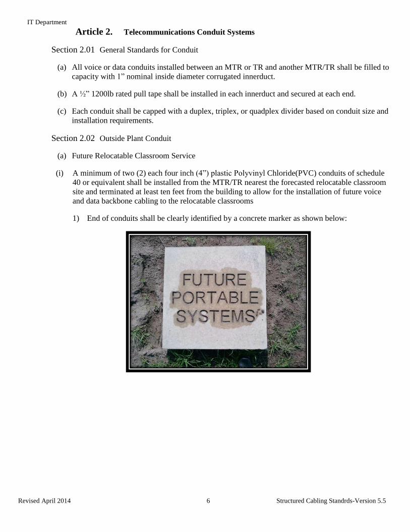
1) End of conduits shall be clearly identified by a concrete marker as shown below:
IT Department
Revised April 2014 7 Structured Cabling Standrds-Version 5.5
Article 3. Telecommunications Rooms
Section 3.01 Telecommunications Room Design and Build-out Requirements
(a) Engineer or designer shall consult w/ the current Information Technology Department project
contact to determine specific MTR/TR layout needs.
(b) Engineer or designer shall provide detail drawings for MTR and each TR in the telecom section of
drawings. Detail drawings shall include at a minimum:
(i) Front views of each equipment rack to be installed in the respective MTR/TR showing actual
LIU and horizontal patch panel locations and quantity, type and quantity of cables to be
terminated on said patch panel, panel numbers and jack labels, and open space for customer
provided equipment
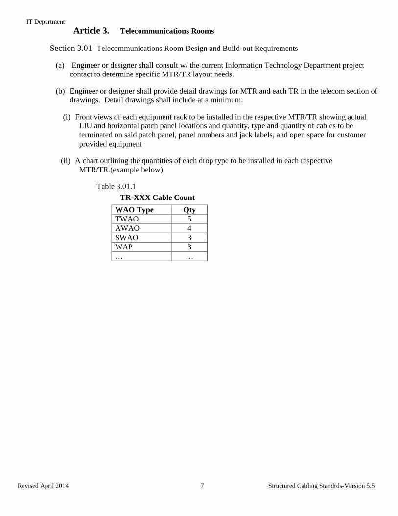
(ii) A chart outlining the quantities of each drop type to be installed in each respective
MTR/TR.(example below)
Table 3.01.1
TR-XXX Cable Count
WAO Type Qty
TWAO 5
AWAO 4
SWAO 3
WAP 3
… …
IT Department
Revised April 2014 8 Structured Cabling Standrds-Version 5.5
(iii) Each detail drawing shall be clearly labeled by TR’s FISH number.
(c) All TRs shall be designed with sufficient floor space to facilitate the use of floor standing racks
for the support of all voice and data cabling and electronics.
(i) The use of wall mounted racks, either swing-gate or fixed is prohibited unless prior written
approval is given by the current Information Technology Department project contact. These
types of racks are notoriously difficult for District IT staff and vendors to service once
electronics, fiber jumpers, and copper patch cords have been installed in/on them.
(d) Each MTR and TR shall have a drop ceiling set at 10’AFF.
(e) All TRs shall have 3/4” plywood backboard covering all four (4) walls from 12” AFF to a height
of 9’ AFF. All plywood backboard shall be painted with 2 coats fire retardant on all 6 sides. All
plywood backboard shall be A/C grade with the "A" side out.
(f) Ladder rack shall be installed around perimeter of TR at 8’ AFF. All floor standing racks shall be
mechanically bonded to the installed ladder rack for support.
(i) Ladder rack should be Chatsworth Products Inc. Cable Runway® and Radii Bends® or
approved equal. A minimum width of 12” is required.
(ii) A cable runway radius drop (waterfall) must be used to support cables transitioning from ladder
tray to equipment racks or another cable tray above or below the transition point.
Section 3.02 Equipment Rack and Enclosure Requirements
(a) Floor mounted equipment racks (ER)
(i) A standard 84” two post rack shall be provided and securely fastened to bare concrete or tile
floor.
(ii) Isolation pads shall be placed between the rack and the bare concrete floor.
(b) Enclosures/Cabinets-
(i) Floor mounted equipment cabinets (EC) shall be installed in a manner that allows full access to
both the front and the rear of the cabinet. Where a specific part number is listed, only that part
number will be accepted unless prior written approval is received from the current Information
Technology project contact.
1) 70” Floor-mount EC
a) Hubbell part number HPW70C19X30
IT Department
Revised April 2014 9 Structured Cabling Standrds-Version 5.5
(ii) Wall mounted cabinets shall be mounted in a manner that allows the EC’s front door and center
to swing fully open. Additionally, all wall mounted cabinets shall be affixed to a ¾” plywood
backboard that has been painted with a fire retardant paint.
1) 48” Wall-mount/Floor-mount EC
a) Hubbell part number HSQ4826
2) 36” Wall-mount/Floor-mount EC
a) Hubbell part number HSQ3626
Section 3.03 Equipment Rack Cable Management
(a) Approved vertical and horizontal wire management is listed below (no other models will be
accepted under ANY circumstances):
(i) Horizontal Management – Panduit Part # WMPH2E
(ii) Vertical Management – Panduit Part # WMPVHC45E
IT Department
Revised April 2014 10 Structured Cabling Standrds-Version 5.5
Article 4. Support Systems
Section 4.01 TBD
Article 5. Electrical Power
Section 5.01 General Power Requirements
(a) All power outlets that serve communications rooms shall originate from a branch panel that serves
only this sensitive equipment.
(b) Any and all circuits serving an MTR or TR are critical for building support and life safety systems
(Voice, Data, BMS, EMS, A/C controls, security, surveillance, etc) and are required to be
serviced by the site’s backup generator.
Section 5.02 Power Conditioning and Protection Requirements
(a) Transient voltage surge suppression (TVSS) systems shall be installed, at a minimum, in front of
every branch panel that will service communications rooms and equipment.
Section 5.03 Telecommunications Room Power Requirements
(a) A duplex NEMA5-20R receptacle serviced by a single 20Amp circuit shall be installed at a
minimum of every three feet (3’) at 18” AFF on all four (4) walls in all TR.
(b) A quad NEMA5-20R serviced by two 20Amp circuits, one circuit per duplex receptacle, shall be
provided at the base of each floor-mounted equipment rack. The installation method shall not
interfere with any horizontal or riser cable routing into the management, owner provided
equipment placement or create the potential for EMI.
(c) Any special receptacle and power needs will be specified on an individual project basis. Please
see current Information Technology Department project contact for locations and quantities of
special receptacles.
Section 5.04 Equipment Cabinet Power Requirements
(a) All equipment cabinets shall receive a duplex NEMA5-20R serviced by a single 20AMP circuit
mounted inside of the equipment cabinet in the top right corner in manner that does not interfere
with the locking mechanism of the cabinet or equipment mounting.
IT Department
Revised April 2014 11 Structured Cabling Standrds-Version 5.5
Article 6. Telecommunications Systems Grounding/Bonding
Section 6.01 Design
(a) Grounding and bonding systems shall be designed using the TIA-942, ANSI/J-STD- 607-A, NEC
800.90(A), NEC 250 and NFPA 780 standards. Whenever two or more standards are in conflict
with one another, the more stringent standard applies.
Section 6.02 Specific Grounding Requirements
(a) Relocatable Classroom Grounding and Bonding Requirements
(i) A TBB shall be installed in a relocatable classroom TR’s equipment cabinet (EC) and shall be
bonded directly to the nearest electrical panel ground using a green insulated 6 AWG
conductor. In cases where running a ground conductor to the nearest electrical panel is not
possible, a ground conductor shall be bonded to the structural steel of the relocatable
classroom.
Article 7. Environmental Requirements for Telecommunications Rooms
Section 7.01 Room Conditioning Requirements
(a) A single room AC unit shall be installed in the MTR and each TR located in a building to allow
the temperature in each MTR and TR to be maintained at the optimum level separate from the
building HVAC systems.
Section 7.02 Temperature Requirements
(a) All MTRs and TRs should be kept at a temperature range of 68-75 degrees Fahrenheit per BICSI
TDM Ch 8-19.
IT Department
Revised April 2014 12 Structured Cabling Standrds-Version 5.5
Article 8. Horizontal Structured Cabling-- Cabling and connectivity installed in any St
Johns County School District building must carry at a minimum a 20 year warranty through the
cable manufacturer that will apply to the complete end-to-end installed solution. EIA/TIA
Standard 568B wiring scheme shall be used for all horizontal cabling terminations. Horizontal
Cat6 copper cable must be rated for installation in plenum spaces and be rated at 250 Mhz or
better. Cabling contractors shall possess AMP NDNI or Panduit PCI and Corning ECP
manufacturer certifications.
Section 8.01 Approved Horizontal Copper Cabling Manufacturers
(i) AMP Category 6e UTP cable (minimum)
(ii) Belden DataTwist 2400 (non-bonded or bonded-pair) (minimum)
(iii) Berk-Tek LANmark-2000 (minimum)
Section 8.02 Horizontal Cabling Color Codes
The jacket color for all horizontal data cable installed in St Johns County School District building shall
follow the color codes listed below.
(a) Data- Yellow jacket
(b) Voice- Green jacket
(c) Wireless Access Point- Blue jacket
(d) Security, fire, building automation device or audio visual controller- White jacket
IT Department
Revised April 2014 13 Structured Cabling Standrds-Version 5.5
Section 8.03 Communications Work Area Outlets (WAO)
(a) Administrative WAO (AWAO)
(i) An administrative WAO should consist of one (1) Cat6 voice connection and one (1) Cat6 data
connection.
(ii) Each administrative area/office shall have a minimum of two administrative WAOs on
opposite sides of the room and each WAO shall be no more than two feet away from power.
(b) Teacher WAO (TWAO)
(i) A teacher WAO shall consist of one (1) Cat6 voice connection, one (1) Cat6 data connection.
(ii) Each classroom and resource room shall have one teacher WAO and each WAO shall be no
more than two feet away from power
(c) Workrooms/Storage Rooms/School Store WAO (SWAO)
(i) A Workroom/Storage Room/School Store WAO shall consist of one (1) Cat6 voice connection
and one (1) Cat6 data connection
(ii) Each Workroom/Storage Room/School Store shall have one Workroom/Storage Room/School
Store WAO that is no more than two feet away from power.
(d) Classroom\Resource Room WAO (CWAO)
(i) A classroom WAO shall consist of three (3) Cat6 data connections
(ii) Each classroom and resource room shall have a minimum of two WAOs and each WAO should
be no more than two feet away from power.
(e) Media Center WAO (MWAO)
(i) A Media Center WAO shall consist of four (4) Cat6 data connections.
(ii) The exact quantity and placement of Media Center WAOs will be determined by room size and
furniture layout.
(f) Kitchen/Cafeteria Manager Office WAO (KWAO)
(i) A Kitchen/Cafeteria Manager Office WAO shall consist of one (1) Cat6 data connections and
(2) Cat6 voice connections terminated using shuttered jacks.
IT Department
Revised April 2014 14 Structured Cabling Standrds-Version 5.5
(g) Wireless Access Point (WAP) WAO (WAP)
(i) A wireless access point WAO shall consist of two (2) Cat6 data connections
(ii) The exact quantity and placement of Wireless Access Point WAOs will be determined by
building size and layout. It should be assumed that ALL areas of a building shall require
complete, full, and redundant coverage. WAP WAOs shall be installed above the drop ceiling
and terminated in a 2 position surface mount (biscuit) box (Panduit part # CBXS2EI-A or AMP
part # 1116698-3) w/ 10’ of service loop at the station end to allow for a wireless access point
to be placed where needed by the IT Department. (see Section 10 for Wireless LAN Design
requirements)
(iii) All WAP cables shall be terminated together on a patch panel that does not contain voice and
data cables
(h) Cafeteria Point of Sale WAO (PWAO)
(i) A Cafeteria Point of Sale WAO shall consist of two (2) Cat6 data connections terminated using
shuttered jacks.
(i) Classroom AV WAO (AVWAO)
(i) A Classroom AV WAO shall consist of one (1) Cat6 data connection to provide data
connectivity classroom AV interface panel.
(ii) Drop shall terminate in a male RJ-45 connector at the station side.
Section 8.04 Patch panels and Faceplates
(a) Modular patch panels are to be used for horizontal copper connectivity. Approved manufacturers
are Panduit (Part # CPP24FMWBL 24 port unloaded or Part# CPP48FMWBL 48 port unloaded)
or AMP (Part # 1116749-1 24 port unloaded or 1375119-1 48 port unloaded).
(b) Faceplates will have two (2) or four (4) positions and must be angled. Only Panduit Part #
CFPSE4EI (4 port only) or AMP Part #1375155 (2 port) or Part # 406185( 4 port) will be
accepted.
Section 8.05 Cat6 Modular Jack Color Codes and Part Numbers- Color codes shall be used for all
modular jacks including both station and telecommunications rack side.
(a) Yellow- Data
(i) Panduit part # CJ688TGYL or
(ii) AMP part # 1375187-8
(b) Green – Voice
(i) Panduit part # CJ688TGGR or
(ii) AMP part # 1375187-9
(c) Blue – Wireless
IT Department
Revised April 2014 15 Structured Cabling Standrds-Version 5.5
(i) Panduit part # CJ688TGBU or
(ii) AMP part # 1375187-6
(d) Red – Telco Provider Demark Extension
(i) Panduit part # CJ688TGRD or
(ii) AMP part # 1375187-7
(e) White – Building controls connections to include security, fire, BMS/EMS, and Classroom A/V
(i) Panduit part # CJ6X88TGIW
(ii) AMP part # 1375055-3
IT Department
Revised April 2014 16 Structured Cabling Standrds-Version 5.5
Article 9. Backbone Cabling and Installation
Section 9.01 Copper Backbone Cabling
(a) All Copper Backbone cabling shall consist of a Cat5 multi-conductor cable and a minimum of 25
pairs shall be installed between an MTR and TR.
Note: Copper backbone specifications for TRs that service relocatable classrooms fall under
section 13.03.
(i) Approved multi-conductor copper cabling manufacturers are as follows:
1) TBD
(b) Inside Riser Copper Cabling Terminations
(i) All inside riser copper backbone cabling shall terminate on standard Cat5 rated 110 punchdown
blocks that have been mounted to the installed backboard forming a wall field.
(c) Outside Plant Copper Cabling Terminations
(i) All copper backbone cabling that leaves the main footprint of the building and/or travels
underground shall be terminated, at both ends, on lightning protection. A cross connect
consisting of the same number of pairs as the installed outside rated cable should be installed
from the “in” or “protected” side of the lightning protector and terminate on Cat5 rated 110
punch down blocks that have been mounted to the installed backboard forming a wall field.
(d) Copper Backbone Cabling Cross Connects – The District uses a modular approach to its voice
cross connects and requires the installation of tie cables from the 110 block wall field, where
backbone cabling from TR(s) is terminated, to patch panels (part number below) mounted in data
racks in each MTR/TR.
(i) Standard MTR Cross Connect Requirements
1) A minimum of 50 pairs of Cat5 rated multi-conductor copper cabling shall be installed from
the 110 block wall field to the data rack that houses the site’s IP Voice Gateway and shall
terminate on standard 110-style Cat5 patch panels (Panduit Part #DP485E88TG or AMP Part
#406331-1) using 1 pair per patch panel port on the blue pair to serve as a cross connect. The
District IT staff will be responsible for making the final cross connects between the 110 side
of the cross connect and the 110 wall field made up of the 50 pair cables to the TRs during
the IP Voice Gateway installation to bring phone service to the TRs based on need.
(ii) Standard TR Cross Connect Requirements
1) Copper backbone cabling installed between a site’s MTR and a TR that does not require
lightning protection shall have 10’ of usable service located in the ladder rack and shall
terminate at the TR directly on on standard 110-style Cat5e patch panels (Panduit Part
#DP485E88TG or AMP Part #406331-1) using 1 pair per patch panel port on the blue pair.
2) If the path from the MTR to the TR requires the use of lightning protection, a pigtail shall be
installed from the “in” or “protected” side of the lightning protection to a standard 110-style
IT Department
Revised April 2014 17 Structured Cabling Standrds-Version 5.5
Cat5e patch panel (Panduit Part #DP485E88TG or AMP Part #406331-1) ,located in the TR’s
data cabling rack, using 1 pair per patch panel port on the blue pair at the patch panel end.
Section 9.02 Fiber Optic Backbone Cabling
(a) Approved Fiber Optic Connectivity Manufacturers- The manufacturers listed below are approved.
The proposed fiber optic cable and connectors must both be sourced from one of the approved
manufacturers.
(i) Corning
(b) Approved Fiber Optic Connectivity Product Lines
(i) Corning Pretium Rack and Wallmount Enclosures
(ii) Corning Pretium Unicam Connectors
(c) A minimum of twenty-four (24) strands of multimode and twelve (12) strands of single-mode
fiber optic cabling shall be installed between the building MTR and each building TR. Note:
Optical fiber backbone specifications for TRs that service relocatable classrooms fall under
section 13.03.
(d) Unless otherwise recommended by the manufacturer, all fiber cables shall be run in innerduct. All
strands will be terminated in the MTR/TR using approved SC type connectors in wall mounted
interconnect centers(must have prior Information Technology project contact approval) or
Pretium rack mounted LIUs equipped with sufficient ports, slack storage space and splice tray
storage, if required, to terminate and secure all fibers.
(e) Fiber Optic Cable Requirements
(i) The fiber optic cabling included in the solution must be optimized for a 10Gbps VCSEL system
(OM3).
(ii) All multimode fiber optic backbone cabling shall have a core diameter of 50 microns and a core
cladding diameter of 125 microns.
(iii) All single-mode fiber optic backbone cabling installed shall have a core diameter of 8-9 microns
and a core cladding diameter of 125 microns and shall be terminated with blue SC or LC
connectors
IT Department
Revised April 2014 18 Structured Cabling Standrds-Version 5.5
Article 10. Wireless Voice and Data Network Design Requirements
Section 10.01 Wireless Design Requirements
(a) The exact quantity and placement of Wireless Access Point WAOs will be determined by building
size and layout. It should be assumed that ALL areas of every building shall require complete,
full, and redundant coverage. Required areas include but are not limited to; the gym, auditorium,
cafeteria, media center, all administrative spaces, and all classroom and learning spaces, outlying
PE buildings, etc.
(b) SJCSD requires that a wireless WAO is installed in every room (including but not limited to
classrooms, conference rooms, storage rooms, offices, kitchen, etc) of the building with common
areas such as gym, cafeteria and auditorium receiving additional locations based on size
(c) Signal strength requirements shall be built around current best practice standards for a heavily
utilized enterprise class wireless LAN that will support both data and wireless IP telephony. AP
quantity and placement shall be optimized for signal density with the target signal-to-noise-ratio
(SNR) of -67dB.
Section 10.02 Standard Wireless Equipment- Wireless networks designed and implemented for the
SJCSD shall consist of the electronics listed below. All design considerations and site survey planning
calculations shall be based off of the following models.
(a) Access Points
1) Aerohive APs meeting 802.11n or 802.11ac w/ minimum 3x3x3 MIMO
(b) Management Platform
1) Aerohive HiveManager
IT Department
Revised April 2014 19 Structured Cabling Standrds-Version 5.5
Article 11. Labeling and Administration- EIA/TIA 606-A specification shall be used as a
guideline
Section 11.01 MTR/TR Identification
(a) MTR
(i) A building MTR shall be labeled as follows:
MTR-XXX
where XXX is the FISH number that will be permanently associated with the room. This label shall be
permanently mounted in plain view on both the inside and outside of the door for easy identification.
(b) TR
(i) A building TR shall be labeled as follows:
TR-XXX
where XXX is the FISH number that will be permanently associated with the room. This label shall be
permanently mounted in plain view on both the inside and outside of the door for easy identification.
Section 11.02 Horizontal Connectivity Labeling
(a) Patch Panel Labeling
(i) Each patch panel shall be labeled with a number in the top left corner. This number shall be in
ascending order from top left to right bottom.
(ii) Each port on a patch panel in a MTR or TR shall be labeled with the room number and an
uppercase letter, A-Z, that corresponds to the faceplate and port labels at the station side of
each link.
(b) Individual Horizontal Station Cable Labeling
(i) Each station cable shall be labeled 2” from the termination with a permanent, water resistant,
electronically generated, sticker-type label, using the following scheme:
TRXXX-Y-nnnV
Where XXX stands for the FISH number of the TR that the cabling originates from and Y stands
for the number of the patch panel on which the cabling terminates in TRXXX and where nnn
stands for the FISH number of the room the drop is located in and the V is a consecutive
identifier (A,B,C,D,etc) for each cable in the room. In the event that a single room contains
more than 26 single connections double letter designations shall be used to accommodate the
connections over 26 (AA, BB, etc).
IT Department
Revised April 2014 20 Structured Cabling Standrds-Version 5.5
(c) Work Area Outlet Faceplate Labeling
(i) A WAO faceplate shall be labeled using the following scheme:
Top of faceplate - TRXXX-Y
Where XXX stands for the FISH number of the TR that the cabling originates from and Y stands
for patch panel # where the cabling terminates in TRXXX
Each individual outlet on the faceplate – nnnV
Where nnn stands for the FISH number of the room the drop is located in and the V is a
consecutive identifier (A,B,C,D,etc) for each cable in the room starting at the left side of the
room and working clockwise. In the event that a single room contains more than 26 single
connections double letter designations shall be used to accommodate the connections over 26
(AA, BB, etc).
Section 11.03 Backbone Connectivity Labeling
(a) Copper Backbone Cabling shall be labeled on the cable jacket, using a permanent water and tear-
resistant label, three times starting from the patch panel, wall block, or lightning protection and
working down the cable at 12” increments using the following scheme:
Ppair-MTRXXX-TRYYY
Where P stands for the number of pairs in the cable and XXX is the FISH number of the MTR or
TR the cable originates from and YYY is the FISH number of the TR the cable terminates in.
(i) Patch panels used to terminate copper backbone cabling shall be labeled in the top center of each
panel using the following scheme:
Ppair-MTRXXX-TRYYY
Where P stands for the number of pairs in the cable and XXX is the FISH number of the MTR or
TR the cable originates from and YYY is the FISH number of the TR the cable terminates.
(b) Fiber optic backbone cabling shall be labeled on the jacket using a permanent water and heat
resistant label, three times starting from the termination tray and working down the cable at 12”
increments using the following scheme:
Pstrand-S/MM-MTRXXX-TRYYY
Where P stands for the number of strands in the cable and either S or M stands for single-mode
or multimode fiber and XXX is the FISH number of the MTR or TR the cable originates from
and YYY is the FISH number of the TR the cable terminates in.
IT Department
Revised April 2014 21 Structured Cabling Standrds-Version 5.5
Section 11.04 Special Use Outlet Labeling
(a) Wireless Access Point (WAP) WAOs shall be labeled on the biscuit box and on the T-bar of the
drop ceiling directly below the biscuit box with a Yellow ¾” permanent label in plain view using
the following scheme:
TRXXX-Y-WAP-RRR-V
Where XXX stands for the FISH number of the TR that the cabling originates from and Y stands
for the number of the patch panel on which the cabling terminates in TRXXX , the WAP is a
constant, the RRR is the FISH number of the room or corridor that the WAP is located in, and
the V is a consecutive identifier (A,B,C,D,etc) for each WAP located in the same room or
corridor. In the event that a single area contains more than 26 wireless access points a double
letter consecutive identifier shall be used to accommodate the WAPs over 26 (AA, BB, etc).
(b) Media Link Controller (MLC) WAOs shall be labeled on the cable using a permanent cable label
using the following scheme:
TRXXX-Y-MLC-RRR-V
Where XXX stands for the FISH number of the TR that the cabling originates from and Y stands
for the number of the patch panel on which the cabling terminates in TRXXX , the MLC is a
constant, the RRR is the FISH number of the room or commons area that the MLC panel is
located in, and the V is a consecutive identifier (A,B,C,D,etc) for each MLC panel. In the event
that a single building contains more than 26 MLC panels a double letter consecutive identifier
shall be used to accommodate the WAPs over 26 (AA, BB, etc). Note: MLC cables will not be
visible unless the MLC panel is removed from the wall. To see the cable label, remove the four
screws which secure it to the wall to expose the cable.
IT Department
Revised April 2014 22 Structured Cabling Standrds-Version 5.5
Article 12. Testing and Documentation
Section 12.01 Testing shall follow all standards set forth in TIA/EIA-568-B.1, TIA/EIA-568-B.2,
TIA/EIA-568-B.3, TIA/EIA-TSB-140, TIA/EIA-526-14-A, and TIA/EIA-526-7
(a) Horizontal Copper Cabling
(i) Testing and certification of horizontal copper cabling shall be performed using the permanent
link method.
(b) Copper Backbone Cabling
(i) All copper backbone cabling shall be tested for continuity.
(c) Fiber Optic Backbone Cabling
(i) All fiber optic backbone cabling shall be tested and certified using the BICSI Tier 2 method for
testing optical fiber. A launch cable that is a minimum of 200 meters in length shall be utilized
during all OTDR tests to ensure accurate trace results.
Section 12.02 Documentation
(a) Submitting Test Results
(i) Cabling test results for Move, Add, or Change projects or Summer Relocatable Classroom
installs shall be submitted via electronic mail to the address below:
(ii) Cabling test results for large projects such as new schools and large scale additions and
renovations shall include each horizontal copper location and each backbone fiber strand and
must be submitted in triplicate in both of the following form (three each CD/DVD media):
1) Hard copy- Shall be neatly contained in a three-ring binder. The cover of the binder shall be
printed with, at a minimum, the following information, St Johns County school construction
name, school address, cabling contractor and their project manager’s name, and date of
cabling completion. The three-ring binder must have tabbed dividers labeled with the TR that
the tests originated separating each TR’s tests from the others.
2) Digital- CD or DVD media may be used and the files must be in the native database format
of the tester used for testing and certification. (Tab delimited, .CSV files, excel spreadsheets,
or other non-native file formats will not be accepted). The CD or DVD media must have a
computer generated label that includes at a minimum, the following information: St Johns
County school construction name, school address, cabling contractor and their project
manager’s name, and date of cabling completion. In addition to the test results in native
format each CD/DVD shall also contain an installable copy of all necessary proprietary
viewing software for the tester format used in the certification.
IT Department
Revised April 2014 23 Structured Cabling Standrds-Version 5.5
Article 13. Relocatable Classroom Systems Specifications Structured cabling networks for relocatable classrooms are designed and installed to provide the
greatest scalability, flexibility and ease of management.
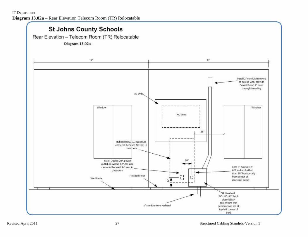
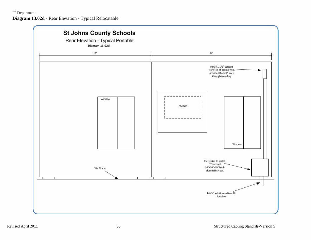
Section 13.01 Relocatable Classroom Conduit System Specifications (See diagrams 13.02a and 13.02d
for external conduit termination routing detail)
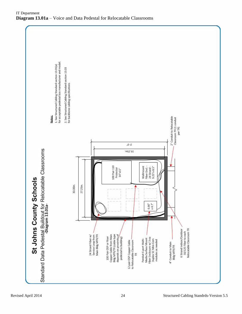
(a) All connectivity will originate from a pedestal, which should be a minimum of a 36” x 36” x 12”
NEMA 3 rated (Acceptable Models - Cooper B-Line part number 363012RHCF or Hoffman
Cabinet part number A36H3612GQRLP) enclosure, securely mounted to/near the relocatable
classroom that houses the first TR installed. All future backbone cabling, both optical fiber and
copper will originate from this enclosure. (See diagram 13.01a for pedestal buildout
requirements)
(b) A minimum of 2 ea 2” or 1 ea 4” conduit should be installed from the in-ground voice and data
network expansion box located closest to the pedestal mounted on/near the relocatable classroom
that is closest to the main building.
(c) A 2” conduit will be installed from each new relocatable classroom TR back to the pedestal using
the most direct path. A 12” x 12” pull box shall be installed at 150’ intervals or every 180 degrees
of bend (or two 90degree bends) in a conduit run to minimize strain on cables.
(d) External boxes shall be a minimum of 16” x 16” x 10” (Acceptable Model -Allied Moulded
Products part # AM1648RL ) and possess a minimum NEMA 3 rating.
(e) A minimum of a 1-1/2” conduit shall be installed in an unbroken path between a relocatable
classroom and nearest TR. Daisy chaining pipes between relocatable classrooms is prohibited due
to the added pull points, added distance, and 90 degree bends created.
(f) A single run of conduit between a relocatable classroom and a TR may contain no more than two
(2) 90 degree bends including the exit from the TR and entrance into the relocatable. Sweep bends
shall be used to minimize pull force needed.
(g) 1-1/2” conduits that will house horizontal copper cabling (Cat5e, Cat6, etc.) shall be no more than
220’ in length, not including turn-ups into the relocatable classroom, from TR to relocatable
classroom being served.
(h) No more than eight (8) cat6 gel-filled cables should be run in any 1-1/2” conduit between a TR
and relocatable classroom.
(i) All conduits shall be clearly marked at both ends and again every twenty-five feet (25’) w/
fluorescent orange spray paint to differentiate voice and data conduits from any other conduits
buried in the same trench.
IT Department
Revised April 2014 24 Structured Cabling Standrds-Version 5.5
Diagram 13.01a – Voice and Data Pedestal for Relocatable Classrooms
IT Department
Revised April 2014 25 Structured Cabling Standrds-Version 5.5
Section 13.02 Relocatable Classroom Horizontal Cabling and Connectivity Specifications
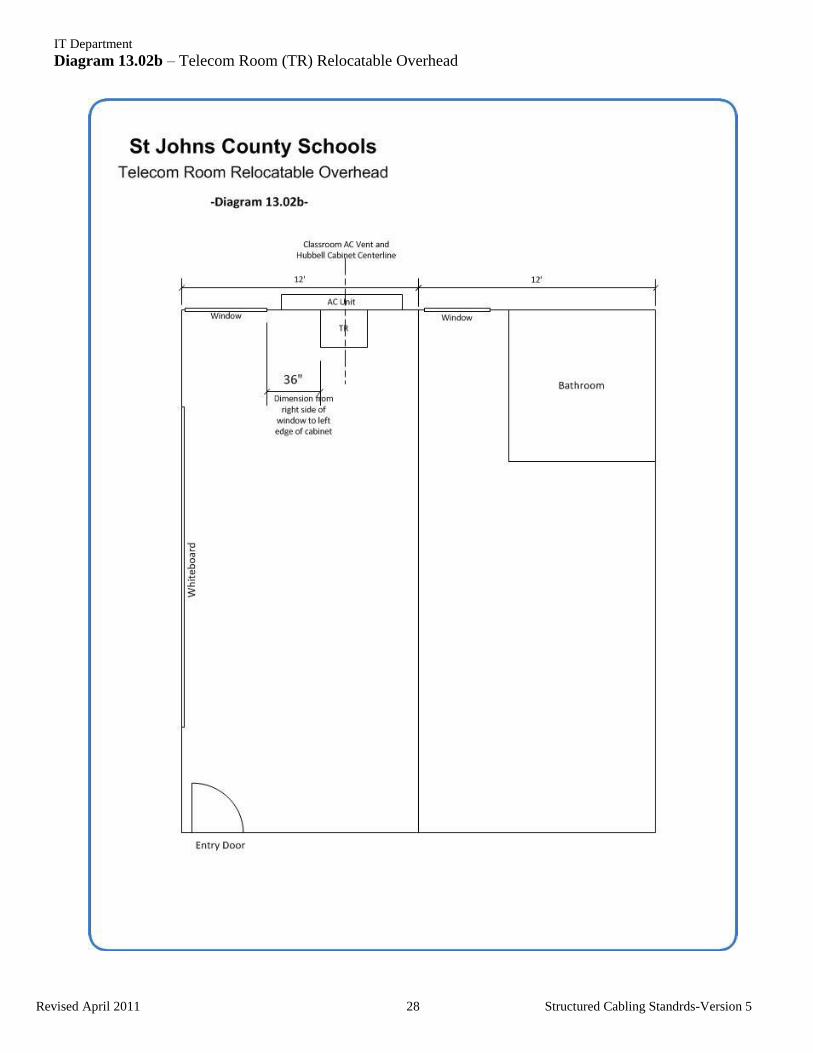
(a) A minimum of a 36” Hubbell Quad Cab (part # HSQ3626) shall be installed in the relocatable that
will serve as the TR. A 38”x28” backboard shall be painted on all six sides with fire-retardent
paint and affixed to the wall. The cabinet shall be mounted to the plywood and set on two
sections of uni-strut to relieve load strain from the wall. (see Diagram 13.02a and 13.02b and
Image 13.02a and 13.02b for placement detail)
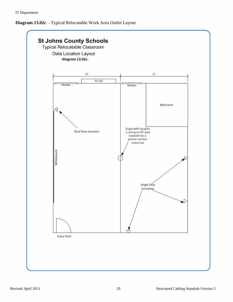
(b) Each relocatable classroom shall receive five (5) gel-filled Cat6 data cables.
(i) See diagram 13.02c for drop location placement detail
(ii) A single drop is to be installed in the ceiling and terminated with a Blue jack in a 2position
surface mount box (Panduit part # CBXS2EI-A or AMP part # 1116698-3) w/ 10’ of service
loop at the station end to allow for a wireless access point to be placed where needed by the IT
Department.
(iii) Approved Horizontal Copper Cabling Manufacturers
1) See Article 8 for horizontal copper cabling requirements.
(c) Connectivity
(i) Copper Connectivity
1) Modular Patch panels are to be used for copper connectivity. Either Panduit (Part #
CPP24FMWBL 24 port unloaded or Part# CPP48FMWBL 48 port unloaded) or AMP (Part #
1116749-1 24 port unloaded or 1375119-1 48 port unloaded).
2) Modular Cat5E jacks are to be used. Colors for each jack at the panel side should match the
color at the station side and follow the owner’s color code.
a) Yellow- Data
i) Panduit part # CJ688TGYL
ii) AMP part # 1375187-8
b) Green – Voice
i) Panduit part # CJ688TGGR
ii) AMP part # 1375187-9
c) Blue – Wireless
i) Panduit part # CJ688TGBU
ii) AMP part # 1375187-6
3) Work area outlets
IT Department
Revised April 2014 26 Structured Cabling Standrds-Version 5.5
a) Faceplates will have two (2) or four (4) positions and must be angled. Only Panduit Part #
CFPSE4EI 4 port only or AMP Part #1375155 2 port or Part # 406185 4 port will be
accepted.
(ii) Management
1) Horizontal- Panduit finger duct where applicable. Space will usually prevent the use of
management in cabinets. If management is requested, use Panduit part # WMPLFSE
IT Department
Revised April 2011 27 Structured Cabling Standrds-Version 5
Diagram 13.02a – Rear Elevation Telecom Room (TR) Relocatable
IT Department
Revised April 2011 28 Structured Cabling Standrds-Version 5
Diagram 13.02b – Telecom Room (TR) Relocatable Overhead
IT Department
Revised April 2011 29 Structured Cabling Standrds-Version 5
Diagram 13.02c – Typical Relocatable Work Area Outlet Layout
IT Department
Revised April 2011 30 Structured Cabling Standrds-Version 5
Diagram 13.02d - Rear Elevation - Typical Relocatable
IT Department
Revised April 2011 31 Structured Cabling Standrds-Version 5
Section 13.03 Relocatable Classroom Backbone Cabling Specifications – (See Diagram 13.01a for
installation detail)
(a) Optical Fiber Backbone Cabling
(i) All fiber optic cabling installed for relocatable classrooms shall meet the specifications outlined
in section 9.02
(ii) 24 strands of 50/125 OM3 multimode optical fiber shall be installed from the main building
MTR located nearest to the newly installed relocatable classroom that will serve as the first
TR. All 24 strands of multimode optical fiber shall terminate in an optical fiber enclosure
located inside the 36”x36” pedestal mounted on/near the portable that will house the first TR.
SC connectors shall be used to terminate all 24 strands of multimode optical fiber.
(iii) Six (6) strands of muilti-mode optical fiber shall be installed from the 36”x36” pedestal located
on/outside the first relocatable classroom TR to each relocatable classroom TR. All six (6)
strands shall be terminated at both ends using SC connectors.
(iv) The connectors for each 6 strand cable installed between the data pedestal and a TR portable
shall be mounted in a standard 1U LIU at the TR portable side and in a Panduit Multi-Media
Surface-Mount Fiber Enclosure with 3 ea Duplex SC Minicom modules as needed at the data
pedestal side.
(v) All optical fiber backbone labeling shall follow the labeling scheme detailed in Section 10.03b
(b) Copper Backbone Cabling
(i) A minimum of 50 pairs of Category 3 copper backbone cabling shall be installed from the main
building MTR/TR located nearest to the pedestal that has been installed on/near the relocatable
classroom that will serve as the first TR. All 50 pairs shall terminate on the “In” side of an
appropriately sized 110 style lightning protector located inside the 36”x36” pedestal.
(ii) A maximum of 12 pairs of copper backbone cabling shall be installed from the 36”x36” pedestal
located on/outside the first relocatable classroom TR to each relocatable classroom TR. Every
pair of each 12 pair cable shall be terminated on the “Out” side of the lightning protection
installed in the 36”x36” pedestal using the next available 12 pairs of the 100 pair cable.
(iii) All copper backbone cabling installed from a pedestal to a relocatable classroom TR shall
terminate at the relocatable classroom side on an appropriately sized Circa 4000N building
entrance terminal.
(iv) All copper backbone cabling shall terminate in the MTR/TR rack and relocatable classroom TR
cabinet on standard Cat5e patch panels (Panduit Part #DPA485E88TG or AMP Part #406331-
1) for voice 1 pair per port on the blue pair at both ends.
(v) All copper backbone cabling shall follow the labeling scheme detailed in Section 10.03a
IT Department
Revised April 2011 32 Structured Cabling Standrds-Version 5
Article 14. Classrom Audio/Visual (AV) Systems
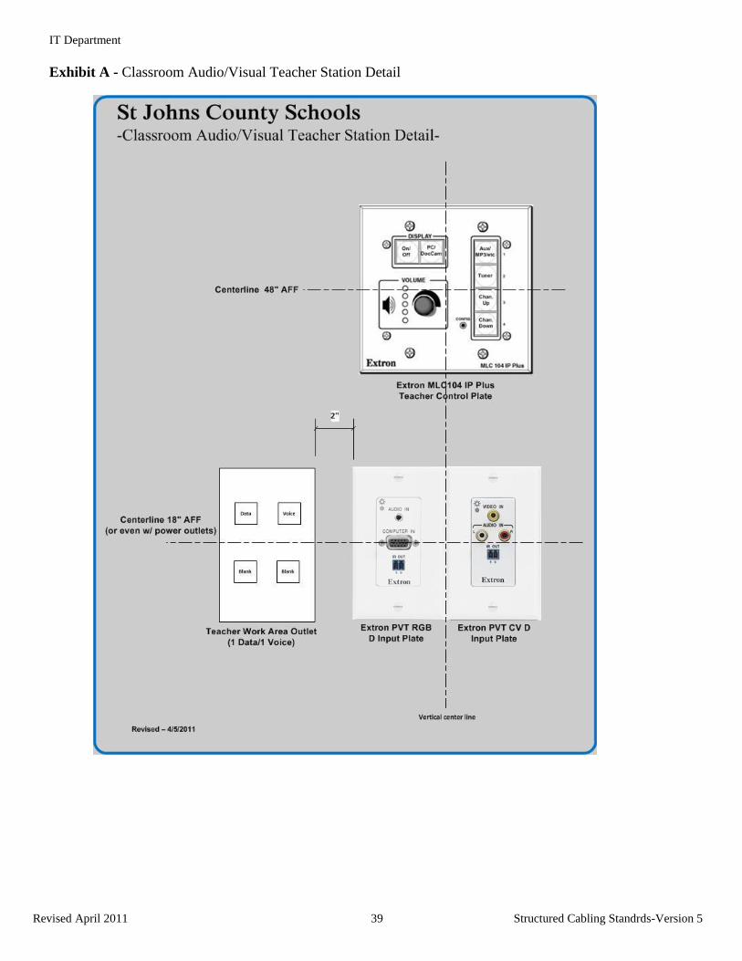
Section 14.01 General Information
The St Johns County School District has standardized on the Extron PoleVault AV switching, control,
and sound reinforcement system for install in all classroom spaces and most commons areas. Large
rooms such as cafetoriums, auditoriums, theatres, etc will require custom systems. Included below are
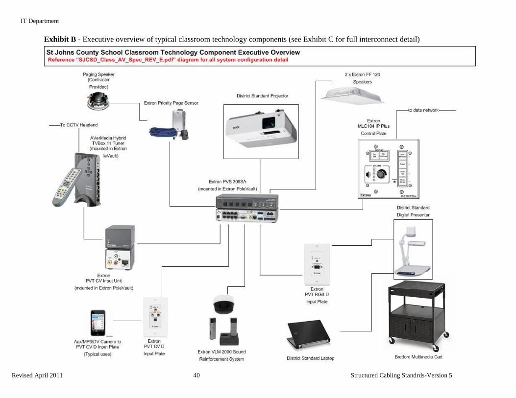
diagrams showing the typical teacher work station detail (Exhibit A), an executive overview of typical
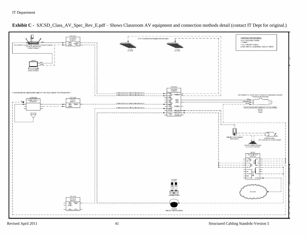
classroom AV components (Exhibit B), an engineering block diagram (Exhibit C) illustrating product
part numbers, interface types and equipment standards that make up a standard classroom audio/visual
(AV) system, and an MLC 104IP Plus button label detail (Exhibit D) showing standard . The following
sections will clearly illustrate all components and connections needed to completely outfit a standard
classroom AV system.
A preliminary model classroom inspection is required when the overall building construction has
reached a stage where total system demonstration is possible. When that time comes, the AV contractor
shall install all pieces of the proposed system and demonstrate complete system functionality to St Johns
County School District IT staff. The demonstration shall take place prior to all other classroom systems
AV being installed. Any questions regarding the text or diagrams listed below shall be directed to the
current Information Technology project contact.
All classrooms will be equipped with a standard easy to operate teacher interface (a tactile button
keypad layout). The audio system may be monaural or stereo for program sound. The instructional
media system will be controlled by a control system with a control panel mounted near the Teacher's
area in accordance with Exhibit A below. System parameters can be monitored, administered and
controlled over the data network. The instructional media equipment will be located within close
proximity to the Teacher's area or through a Graphical User Interface (GUI) on a computer to allow for
ease of operation during instruction.
Acceptable functionality requirements are listed below categorized by type of equipment. Quantities are
listed for movable, portable or loose equipment, and other selected entries. Where quantities are not
listed, refer to the system drawings.
Deviations from this specification must be documented in writing to the Architect and Owner at least ten
business days prior to the submittal date. Written approval must be received from Architect and owner
prior to proceeding with non-standard installation
The System components shall all be correctly listed and labeled by Underwriters Laboratories
Incorporated (UL) for their intended use.
All products shall be new and under warranty at the time of installation. B-stock, previously installed,
refurbished or used equipment shall not be provided on this project.
Where the specification lists several manufacturers for a major item, or group of items, the AV
Integrator shall provide that entire item from one manufacturer only.
The Integrator shall provide all options, accessories and hardware necessary to meet the function of the
design even if they are not specifically listed (i.e. mounting kits, separate or additional power supplies,
input modules, transformers, etc.).
.
IT Department
Revised April 2011 33 Structured Cabling Standrds-Version 5
Section 14.02 PoleVault Contractor Qualification Requirements
(a) Any contractor that will be installing PoleVault systems in a school or district building must be
Authorized Extron Reseller and possess a current Extron Control Associate certification.
Contractors must provide proof with their bid proposal that their company possesses, at the time
of bid submission, the aforementioned certifications.
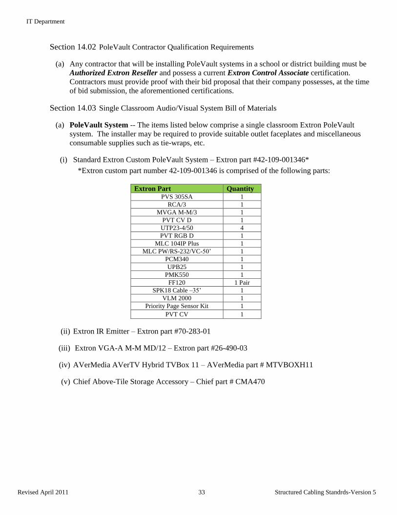
Section 14.03 Single Classroom Audio/Visual System Bill of Materials
(a) PoleVault System -- The items listed below comprise a single classroom Extron PoleVault
system. The installer may be required to provide suitable outlet faceplates and miscellaneous
consumable supplies such as tie-wraps, etc.
(i) Standard Extron Custom PoleVault System – Extron part #42-109-001346*
*Extron custom part number 42-109-001346 is comprised of the following parts:
Extron Part Quantity PVS 305SA 1
RCA/3 1
MVGA M-M/3 1
PVT CV D 1
UTP23-4/50 4
PVT RGB D 1
MLC 104IP Plus 1
MLC PW/RS-232/VC-50’ 1
PCM340 1
UPB25 1
PMK550 1
FF120 1 Pair
SPK18 Cable –35’ 1
VLM 2000 1
Priority Page Sensor Kit 1
PVT CV 1
(ii) Extron IR Emitter – Extron part #70-283-01
(iii) Extron VGA-A M-M MD/12 – Extron part #26-490-03
(iv) AVerMedia AVerTV Hybrid TVBox 11 – AVerMedia part # MTVBOXH11
(v) Chief Above-Tile Storage Accessory – Chief part # CMA470
IT Department
Revised April 2011 34 Structured Cabling Standrds-Version 5
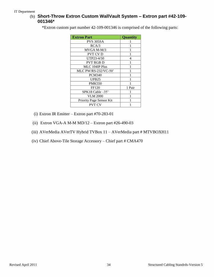
(b) Short-Throw Extron Custom WallVault System – Extron part #42-109-001346*
*Extron custom part number 42-109-001346 is comprised of the following parts:
Extron Part Quantity PVS 305SA 1
RCA/3 1
MVGA M-M/3 1
PVT CV D 1
UTP23-4/50 4
PVT RGB D 1
MLC 104IP Plus 1
MLC PW/RS-232/VC-50’ 1
PCM340 1
UPB25 1
PMK550 1
FF120 1 Pair
SPK18 Cable –35’ 1
VLM 2000 1
Priority Page Sensor Kit 1
PVT CV 1
(i) Extron IR Emitter – Extron part #70-283-01
(ii) Extron VGA-A M-M MD/12 – Extron part #26-490-03
(iii) AVerMedia AVerTV Hybrid TVBox 11 – AVerMedia part # MTVBOXH11
(iv) Chief Above-Tile Storage Accessory – Chief part # CMA470
IT Department
Revised April 2011 35 Structured Cabling Standrds-Version 5
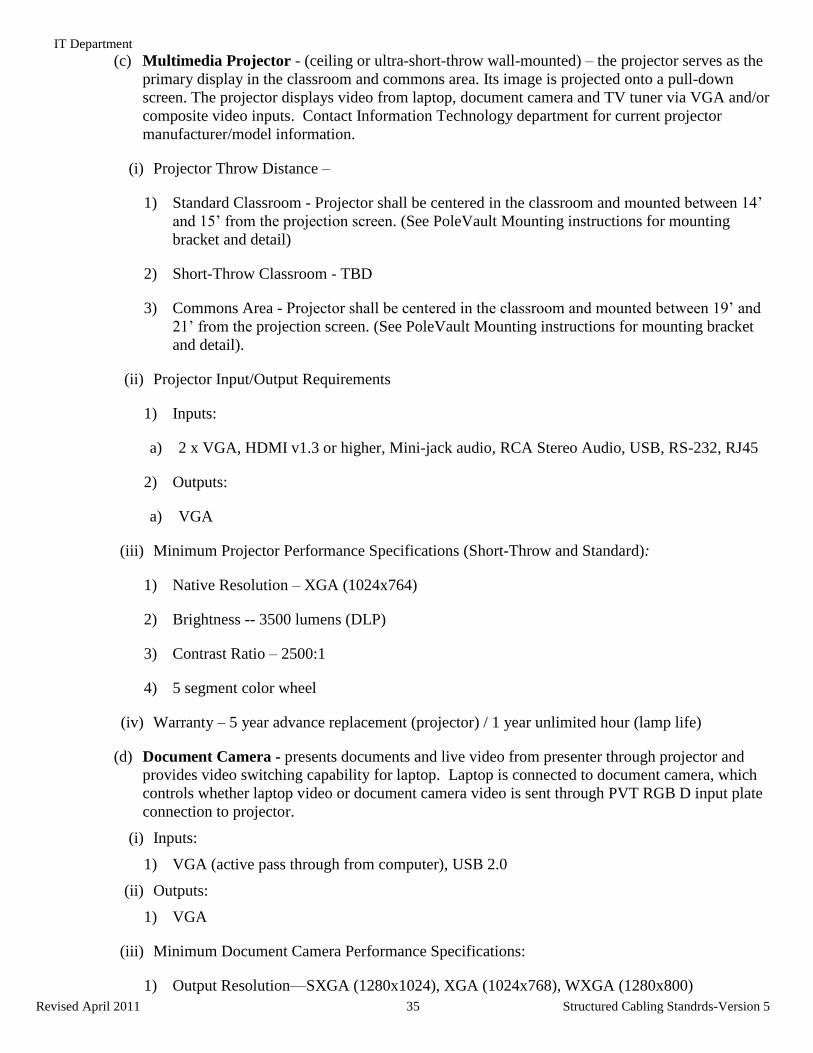
(c) Multimedia Projector - (ceiling or ultra-short-throw wall-mounted) – the projector serves as the
primary display in the classroom and commons area. Its image is projected onto a pull-down
screen. The projector displays video from laptop, document camera and TV tuner via VGA and/or
composite video inputs. Contact Information Technology department for current projector
manufacturer/model information.
(i) Projector Throw Distance –
1) Standard Classroom - Projector shall be centered in the classroom and mounted between 14’
and 15’ from the projection screen. (See PoleVault Mounting instructions for mounting
bracket and detail)
2) Short-Throw Classroom - TBD
3) Commons Area - Projector shall be centered in the classroom and mounted between 19’ and
21’ from the projection screen. (See PoleVault Mounting instructions for mounting bracket
and detail).
(ii) Projector Input/Output Requirements
1) Inputs:
a) 2 x VGA, HDMI v1.3 or higher, Mini-jack audio, RCA Stereo Audio, USB, RS-232, RJ45
2) Outputs:
a) VGA
(iii) Minimum Projector Performance Specifications (Short-Throw and Standard):
1) Native Resolution – XGA (1024x764)
2) Brightness -- 3500 lumens (DLP)
3) Contrast Ratio – 2500:1
4) 5 segment color wheel
(iv) Warranty – 5 year advance replacement (projector) / 1 year unlimited hour (lamp life)
(d) Document Camera - presents documents and live video from presenter through projector and
provides video switching capability for laptop. Laptop is connected to document camera, which
controls whether laptop video or document camera video is sent through PVT RGB D input plate
connection to projector.
(i) Inputs:
1) VGA (active pass through from computer), USB 2.0
(ii) Outputs:
1) VGA
(iii) Minimum Document Camera Performance Specifications:
1) Output Resolution—SXGA (1280x1024), XGA (1024x768), WXGA (1280x800)
IT Department
Revised April 2011 36 Structured Cabling Standrds-Version 5
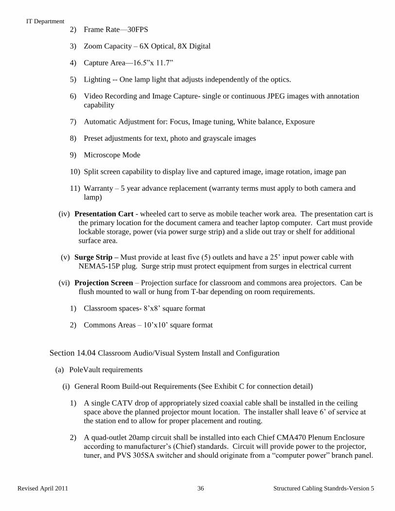
2) Frame Rate—30FPS
3) Zoom Capacity – 6X Optical, 8X Digital
4) Capture Area—16.5”x 11.7”
5) Lighting -- One lamp light that adjusts independently of the optics.
6) Video Recording and Image Capture- single or continuous JPEG images with annotation
capability
7) Automatic Adjustment for: Focus, Image tuning, White balance, Exposure
8) Preset adjustments for text, photo and grayscale images
9) Microscope Mode
10) Split screen capability to display live and captured image, image rotation, image pan
11) Warranty – 5 year advance replacement (warranty terms must apply to both camera and
lamp)
(iv) Presentation Cart - wheeled cart to serve as mobile teacher work area. The presentation cart is
the primary location for the document camera and teacher laptop computer. Cart must provide
lockable storage, power (via power surge strip) and a slide out tray or shelf for additional
surface area.
(v) Surge Strip – Must provide at least five (5) outlets and have a 25’ input power cable with
NEMA5-15P plug. Surge strip must protect equipment from surges in electrical current
(vi) Projection Screen – Projection surface for classroom and commons area projectors. Can be
flush mounted to wall or hung from T-bar depending on room requirements.
1) Classroom spaces- 8’x8’ square format
2) Commons Areas – 10’x10’ square format
Section 14.04 Classroom Audio/Visual System Install and Configuration
(a) PoleVault requirements
(i) General Room Build-out Requirements (See Exhibit C for connection detail)
1) A single CATV drop of appropriately sized coaxial cable shall be installed in the ceiling
space above the planned projector mount location. The installer shall leave 6’ of service at
the station end to allow for proper placement and routing.
2) A quad-outlet 20amp circuit shall be installed into each Chief CMA470 Plenum Enclosure
according to manufacturer’s (Chief) standards. Circuit will provide power to the projector,
tuner, and PVS 305SA switcher and should originate from a “computer power” branch panel.
IT Department
Revised April 2011 37 Structured Cabling Standrds-Version 5
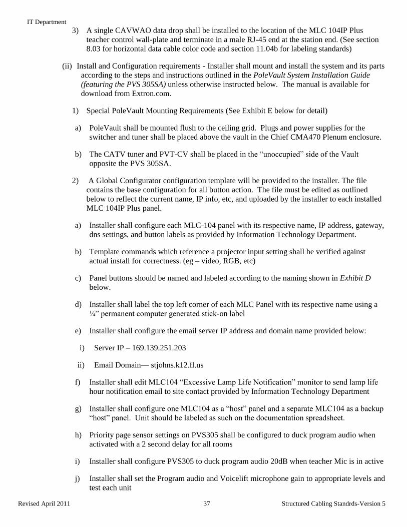
3) A single CAVWAO data drop shall be installed to the location of the MLC 104IP Plus
teacher control wall-plate and terminate in a male RJ-45 end at the station end. (See section
8.03 for horizontal data cable color code and section 11.04b for labeling standards)
(ii) Install and Configuration requirements - Installer shall mount and install the system and its parts
according to the steps and instructions outlined in the PoleVault System Installation Guide
(featuring the PVS 305SA) unless otherwise instructed below. The manual is available for
download from Extron.com.
1) Special PoleVault Mounting Requirements (See Exhibit E below for detail)
a) PoleVault shall be mounted flush to the ceiling grid. Plugs and power supplies for the
switcher and tuner shall be placed above the vault in the Chief CMA470 Plenum enclosure.
b) The CATV tuner and PVT-CV shall be placed in the “unoccupied” side of the Vault
opposite the PVS 305SA.
2) A Global Configurator configuration template will be provided to the installer. The file
contains the base configuration for all button action. The file must be edited as outlined
below to reflect the current name, IP info, etc, and uploaded by the installer to each installed
MLC 104IP Plus panel.
a) Installer shall configure each MLC-104 panel with its respective name, IP address, gateway,
dns settings, and button labels as provided by Information Technology Department.
b) Template commands which reference a projector input setting shall be verified against
actual install for correctness. (eg – video, RGB, etc)
c) Panel buttons should be named and labeled according to the naming shown in Exhibit D
below.
d) Installer shall label the top left corner of each MLC Panel with its respective name using a
¼” permanent computer generated stick-on label
e) Installer shall configure the email server IP address and domain name provided below:
i) Server IP – 169.139.251.203
ii) Email Domain— stjohns.k12.fl.us
f) Installer shall edit MLC104 “Excessive Lamp Life Notification” monitor to send lamp life
hour notification email to site contact provided by Information Technology Department
g) Installer shall configure one MLC104 as a “host” panel and a separate MLC104 as a backup
“host” panel. Unit should be labeled as such on the documentation spreadsheet.
h) Priority page sensor settings on PVS305 shall be configured to duck program audio when
activated with a 2 second delay for all rooms
i) Installer shall configure PVS305 to duck program audio 20dB when teacher Mic is in active
j) Installer shall set the Program audio and Voicelift microphone gain to appropriate levels and
test each unit
IT Department
Revised April 2011 38 Structured Cabling Standrds-Version 5
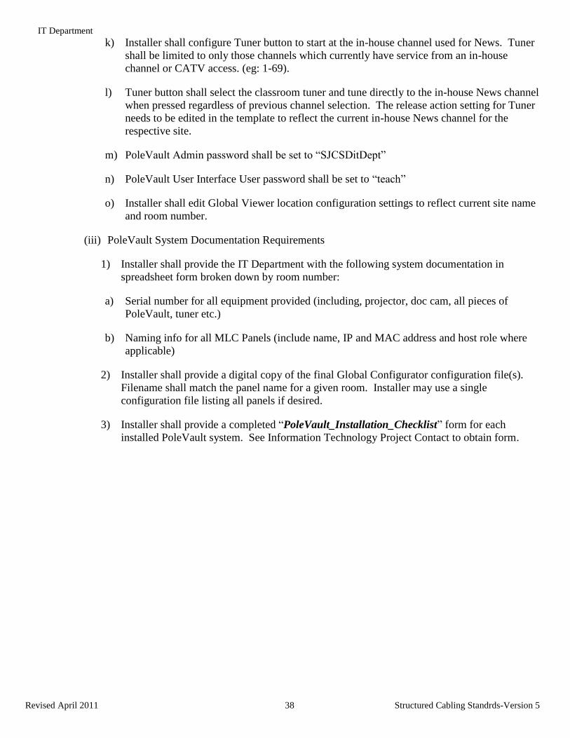
k) Installer shall configure Tuner button to start at the in-house channel used for News. Tuner
shall be limited to only those channels which currently have service from an in-house
channel or CATV access. (eg: 1-69).
l) Tuner button shall select the classroom tuner and tune directly to the in-house News channel
when pressed regardless of previous channel selection. The release action setting for Tuner
needs to be edited in the template to reflect the current in-house News channel for the
respective site.
m) PoleVault Admin password shall be set to “SJCSDitDept”
n) PoleVault User Interface User password shall be set to “teach”
o) Installer shall edit Global Viewer location configuration settings to reflect current site name
and room number.
(iii) PoleVault System Documentation Requirements
1) Installer shall provide the IT Department with the following system documentation in
spreadsheet form broken down by room number:
a) Serial number for all equipment provided (including, projector, doc cam, all pieces of
PoleVault, tuner etc.)
b) Naming info for all MLC Panels (include name, IP and MAC address and host role where
applicable)
2) Installer shall provide a digital copy of the final Global Configurator configuration file(s).
Filename shall match the panel name for a given room. Installer may use a single
configuration file listing all panels if desired.
3) Installer shall provide a completed “PoleVault_Installation_Checklist” form for each
installed PoleVault system. See Information Technology Project Contact to obtain form.
IT Department
Revised April 2011 39 Structured Cabling Standrds-Version 5
Exhibit A - Classroom Audio/Visual Teacher Station Detail
IT Department
Revised April 2011 40 Structured Cabling Standrds-Version 5
Exhibit B - Executive overview of typical classroom technology components (see Exhibit C for full interconnect detail)
IT Department
Revised April 2011 41 Structured Cabling Standrds-Version 5
Exhibit C - SJCSD_Class_AV_Spec_Rev_E.pdf – Shows Classroom AV equipment and connection methods detail (contact IT Dept for original.)
IT Department
Revised April 2011 42 Structured Cabling Standrds-Version 5
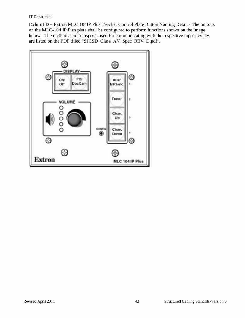
Exhibit D – Extron MLC 104IP Plus Teacher Control Plate Button Naming Detail - The buttons
on the MLC-104 IP Plus plate shall be configured to perform functions shown on the image
below. The methods and transports used for communicating with the respective input devices
are listed on the PDF titled “SJCSD_Class_AV_Spec_REV_D.pdf”.
IT Department
Revised April 2011 43 Structured Cabling Standrds-Version 5
Exhibit E – Classroom PoleVault Mounting Detail
IT Department
Revised April 2011 44 Structured Cabling Standrds-Version 5
Article 15. Applicable Industry Standards
BICSI, Telecommunications Distribution Methods Manual
ANSI/TIA/EIA-568B, Commercial Building Telecommunications Cabling Standard
TIA/EIA TSB-67 Transmission Performance Specifications for Field Testing of
Unshielded Twisted Pair Cabling Systems
TIA/EIA TSB-140 Additional Guidelines for Field-Testing Length, Loss and Polarity of
Optical Fiber Cabling Systems
TIA/EIA TSB-75, Additional Horizontal Cabling Practices for Open Offices.
ANSI/TIA/EIA-569A, Commercial Building Standard for Telecommunications
Pathways and Spaces
ANSI/TIA/EIA-606A, Administration Standard for Telecommunications Infrastructure of
Commercial Buildings
ANSI/TIA/EIA-607, Commercial Building Grounding and Bonding Requirements for
Telecommunications
TIA-942, Telecommunications Infrastructure Standard for Data Centers
ANSI/NFPA-70
NEC, National Electrical Code
NFPA-101, Life Safety Code
NFPA-780, Standard for the Installation of Lightning Protection Systems
Other applicable NFPA Codes.
ANSI/IEEE Codes, All Applicable Codes.
NESC, National Electrical Safety Code (ANSI/IEEE C-2, overhead and underground
telecommunications cable).
Local Uniform Building Codes