Embed Size (px)
Citation preview
PART 3 CHAPTER 4
ST ABILITY AND WATERTIGHT INTEGRITY JULY 1995
SECTIONS
RULES FOR CLASSIFICATION OF
SHIPS
NEWBUILDINGS
HULL AND EQUIPMENT MAIN CLASS
PAGE
1 General ........................................................................................................... 1 2 General Requirements .. .. .. .. . . . .. .. .. . . .. . .. .. .. . . .. .. . .. . . .. . .. .. . . .. .. .. .. .. .. .. .. .. . .. .. .. . . .. .. .. . .. .. . .. 3 3 Design Requirements . . . . . . . . . . . . . . . . . . . . . . . . . . . . . . . . . . . . . . . . . . . . . . . . . . . . . . . . . . . . . . . . . . . . . . . . . . . . . . . . . . . . . . . . . . 4 4 Watertight Integrity ............................................................................................ 9 5 Determination of Lightweight Data .. .. .. . .. .. . .. .. .. .. .. . .. .. .. .. .. .. .. .. .. . .. . .. .. . .. .. .. .. . .. . .. .. . .. .. 10
DET NORSKE VERITAS CLASSIFICATION AS Veritasveien 1, N-1322 H0Vik, Norway Tel.: +47 67 57 99 00 Fax: +47 67 57 99 11
CHANGES IN THE RULES
General
The present edition of the Rules includes amendments decided by th_e-Boar~ as.-of:June 1995 and supersedes the January 1994 edition of the same chapter.
The Rule changes co_me into force as of 1st of January 1996.
This chapter is valid until superseded by a revised chapter. Supplements will not be issued except for minor amendments and an updated liSt of corrections presented in the introduction booklet. The introduction booklet is normally revised in January and July each year.
Revised chapters will be forwarded to all subscribers to the Rules. Buyers of reprints are advised to check the updated list of Rule chapters printed on the front page of the introduction booklet to ensure that the chapter is current.
© Det Norske Veritas
Main changes
• Sec.I. General
- item C102 has been amended
• Sec.3. Design Requirements
- item AlOl has been made applicable to all ships - a new item Al02 with equivalent stability criteria has been added.
Existing items Al02 ana Al03 have been renumbered - the new item 104 has been amended and a new Table Al has
been added - item A200 has been replaced with the full text of the IMO
Weather Criterion - item 0101 has been amended for clarification.
Corrections and Clarifications In addition to the above stated rule amendments, some detected errors have been corrected, and some clarifications. have been made in the existing rule wording.
Computer Typesetting by Division Ship and Offshore, Det Norske Veritas Classification AS Printed in Norway by Det Norske Veritas July 1995
7.95.4500
It is agreed that save as provided below Det Norske Veritas, its subsidiaries, bodies, officers, directors, employees and agents shall have no liability for any loss, damage or expense
b~e~~~ 1;u~hu~:~s~~e~]~h ih~n~~~;~Ko~Y o\h~~~~is~:~1ia~~~:~~g~'i1f~i ~ri:~~~d~1c~b~r~h!Ygi:e~~i~g0b~Ji;sct~r0~~i~i~x<;:c~f~~ ~~i~h:r~'o~nO~tdimr~k~Ve~ft~~~\~i: ~~~~~u;e~~~~?ens~u~~ whether the loss, damage or expense has affected anyone with whom Det Norske Veritas has a contract or a .third party who has acted or relied on decisions made or information given by or on behalf of Det Norske Veritas. * However, if any person uses the services of Det Norske Veritas or its subsidiaries or relies on any decision made or information given by or on behalf of them and in consequence suffers a loss, damage or expense proved to be due to their negligence, omission or default, then Det Norske Veritas will pay by way of compensation to such person a sum representing his proved loss. *In the event Det Norske Veritas or its subsidiaries may be held liable in accordance with the sections above, the amount of compensation shall under no circumstances exceed the amount of the fee, if any, charged for that particular service, decision, advice or information. * Under no circumstances whatsoever shell the individual or individuals who have personally caused the loss, damage or expense be held liable. * In the event that any provision in this section shall be invalid under the law of any jurisdiction, the validity of the remaining provisions shall not.in any way be affected.
CONTENTS
SEC. 1 GENERAL .... ..••.. ........•••....... .. ..•. ...... ... .••• 1
A. Classification ... ...•.. .... ...... .. ..•. ........ .••... ....... ..•. .. .. 1 A 100 Application . . . . . . . . . . . . . . . . . . . . . . . . . . . . . . 1 A 200 Additional class notations . . . . . . . . . . . . . . . . . . . . . . . . . . . . 1
B. Definitions ..................••................•.................... 1 B 100 Symbols . . . . . . . . . . . . . . . . . . . . . . . . . . . . . . . . . . . 1 B 200 Terms . . . . . . . . . . . . . . . . . . . . . . . . . . . . . . . . . . . . . . . . . . . . . . . . . . 1
C. Documentation .•. .. .... ...•.. ...... ...•.. ...... ....... .. .... ....•. 2 C 100 Documentation for approval . . . . . . . . . . . . . 2 C 200 Documentation for information . .. . . . . . . . . . . .. . 2
D. Surveys and Te;ts .....•.... .......... .. ...... ............. ...... 2 D 100 General . . . . . . . . . . . . . . . . . . . . . . . . . . . . . . . . . . . . . . . 2
SEC. 2 GENERAL REQUIREMENTS ••............•....... 3
A. Stability Booklet ..... ...... ..••.. ...... ..•... .. ..... ..... ... .... .. 3 A 100 General . . .. . . . . . . . . . . . . . . . . . . . . . . . . . . . . . . . . . . . . . 3
B. Fixed Ballast .. ..... ...... ...... ...... ..•... .... .. ..•. .. ....... ..•• 3 B 100 General . . . . . . . . . . . . . . . . . . . . . . . . 3
C. Draught Marks .. ...... ...... ..•... ...... ..•... ....... ..•... ...... 3 C 100 General . . . . . . . . . . . . . . 3
D. Loading Computer System . .. .... .. .... .. .... .. .... .. .... .. ... 3 D 100 General . . . . . . . . . . . . . . . . . . . . . . . . . . . . . . . . . . . . . . . . 3
SEC. 3 DESIGN REQUIREMENTS .....................•.•. 4
A. Intact Stability Criteria •.. .. ...... ....••.. ....•. .. ...... ........ 4 A 100 General stability criteria . .. . . . . . . . .. . . . . . . . . . . . . . . . . . .. 4 A 200 Weather criterion . . . . . . . . . . . . . . . . . . 6
B. Free Surface of Liquid in Tanks .. ........... ..••.. ...... .... 7 B 100 General . . . . . . . . . . . . . . . . . . . . . . . . . . . . . . . . . . . . . . . . . . . . . . . . . . . 7
C. :Loading Conditions .. ..••... .. ...... ..•..... ...... .. ...... ...... 7 C 100 General . . . . . . . . . . . . . . . . . . . . . . . . . . . . . . . . . . . . . . . . . . . . . . 7 C 200 Standard loading conditions . . . .. . . . . .. . . . . .. . . . . 7
D. Calculation of Stability .. ..••.•. .. ...... .. ..••.. .. ...... ...... .. 8 D 100 General . . . . . . . . . . . . . . . . . . . . . . . . . . . . . . . . . . . . . . . . . . . . . . . 8 D 200 Deckhouses and superstructures . . . . . . . . . . . . . . . . 8 D 300 Effect of timber deck cargo . .. . . . . . . .. . . . . . . . . . . 8
E. Damage Stability of Cargo Ships ... ... ...•.. ........ .... .... 8 E 100 Application ... .... . .. .... .. .. .. .. .. .. . .. .. .. .. .. ..... .. ... 8
SEC. 4 WATERTIGHT INTEGRITY ......•................ 9
A. General . . . .. . . . . .. . . . . . . . . . . . . . . . . . . . . •• . . . . . . . .. . . . . . . . . . . . . . . . . . . . 9 A 100 General . . . . . . . . . . . . .. . . . . . . 9
SEC. 5 DETERMINATION OF LIGHTWEIGHT DATA ..•.................................••............... 10
A. Inclining Te;t ....... .. ...... ...... .. ...... ..•..•.. ....... ...... .. 10 A 100 Application ... . ... .. .. . .. .. .. .. .. .. . . . 10 A 200 Procedure . . . . . . . . . . . . . . . . . . . . . . . . . . . . . . . 10
B. Lightweight Survey ..............................••............. 10 B 100 Application . .. . . .. .. . . . . .. .. . .. 10 B 200 Procedure . . . . . . . . . . . . . . . . . . . . . . . . . . . . . . . . . . . . . . . . . . . 10

2
Rules for Ships , July 1995 Pt.3 Ch.4 Sec.1 - Page 1
SECTION 1 GENERAL
Contents
A. Classification A 100 Application A 200 Additional class notations
B. Definitions B 100 Symbols B 200 Terms
C. Documentation C 100 Documentation for approval C 200 Documentation for information
D. Surveys and Tests D 100 General
A. Classification
A 100 Application
101 All vessels are to comply with the stability requirements of this Chapter, as applicable for the main class.
102 The requirements in this Chapter are in compliance with IMO Intact Stability Code (IMO Res. A.749(18)) and with relevant regulations of SOLAS Ch.II-!.
103 SOLAS texts directly quoted are printed in Italics. References to SOLAS regulations are given.
If any part of the rules are subject to discussion or misunderstanding the SOLAS text shall prevail.
104 For vessels with service restrictions as described in Pt. I Ch. I Sec.2 B400, modified stability requirements may be considered if consistent with the applicable service restriction.
A 200 Additional class notations
201 Vessels with additional class notations are to comply with additional stability requirements as given in the appropriate rule chapters.
202 Ships with loading computer systems intended for stability control are to comply with Sec.2 DIOO, and will be assigned the additional class notation LCS (I). The letter I in the bracket specifies that the loading computer system is approved for calculation and control of intact stability. If applicable G for grain stability and D for damage stability may be added, i.e. LCS (I G D).
B 100 Symbols
101
B. Definitions
VCG: Vertical Centre of Gravity GM : Metacentric Height G Z : Righting Lever
B 200 Terms
201 External watertight integrity The capability of the hull structure and its external closing appliances to prevent downflooding to volumes assumed
buoyant. The external watertight integrity includes position and type of closing appliances, alarms, indicators, remote controls and signboards fitted to such appliances.
202 Weathertight Weathertight means that in any sea conditions water will not penetrate into the ship.
203 Watertight Capable of preventing ingress of water during static submersion under a head of water for which the surrounding structure is designed.
A watertight closing appliance is also considered weathertight.
204 Downflooding Ingress of water through external openings to buoyancy volumes.
205 Downflooding angle related to intact stability The minimum heel angle where an external opening without weathertight closing appliance is submerged.
206 Dynamic angle The angle up to which the requirement to area-under-therighting- lever-curve is fulfilled. The dynamic angle can not be more than the downflooding angle.
207 Lightweight Lightweight is the displacement of a ship in tonnes without cargo, fuel, lubricating oil, ballast water, fresh water and feed water in tanks, consumable stores, and passengers and crew and their effects.
The lightweight definition stated in the Stability Manual indicates which items are included or not included in the lightweight.
Guidance note: The approved lightweight data are the data which are approved for the purpose of stability approval and control but not necessarily for determination of the deadweight.
---e-n-d---o- f---G-u- i-d-a -n-c-e---n-o-t-e---
208 First intercept The angle of heel where the righting lever curve intercepts the heeling lever curve for the first time.
The first intercept is also known as the •static angle of heel>.
209 Second intercept The angle of heel where the righting lever cnrve intercepts the heeling lever curve for the second time.
210 Maximum allowable vertical centre of gravity The maximum vertical centre of gravity of the vessel, corrected for free surface effect, which complies with the stipulated stability requirements for the draught in question.
211 Preliminary stability documentation The stability documentation which is based on estimated lightweight data.
212 Final stability documentation The stability documentation which is based on approved lightweight data obtained from an inclining test or lightweight survey.
DET NORSKE VERITAS
Rules for Ships , July 1995 Page 2 - Pt.3 Ch.4 Sec. 1
C. Documentation
C 100 Documentation for approval 101 The following documentation is to be submitted for approval:
- preliminary stability booklet - inclining test procedure - inclining test report - final stability booklet - flooding effect information for dry cargo ships.
Guidance note:. Refer to IMO MSC/Circ.434: Guidelines for the preparation of information on the effect of flooding to be provided to masters of dry cargo ships.
---e-n-d---o-f---G-u-i-d-a -n-c-e---n-o-t-e---
102 For each sister vessel, it is sufficient to submit:
- lightweight survey procedure (inclining test procedure for passenger vessels)
- lightweight survey report (or inclining test report for passenger vessels)
- final stability booklet.
103 If the assignment of class is to be based on the approval of the Flag Administration according to Pt. I Ch. I Sec.3 A900, a copy of the final stability documentation stamped by the Flag Administration and the approval letter issued by the Flag Administration are to be submitted to the Society.
C 200 Documentation for information
201 The following documentation is to be submitted for information:
- general arrangement - body plan, lines plan or offset table - external watertight integrity plan or freeboard plan.
202 For stability documentation, prepared by using an approved stability program system, the Society may accept alternative documentation of hull geometry.
Guidance note: Details of the documentation in 100 and 200 is given in Classification Note No. 20.1 «Stability Documentation - Ships);.
---e-n-d---o-f---G- u-i-d-a-n-c-e---n-o-t-e---
D. Surveys and Tests
D l 00 General
101 The following surveys and tests are to be carried out:
- external watertight integrity survey with respect to un-protected and protected openings together with their closing appliances, alarms, indicators and signboards
- checking of draft marks - remote draft measurement and tank gauging systems - inclining test or lightweight survey.
DET NORSKE VERITAS
Rules for Ships , July 1995 Pt.3 Ch.4 Sec.2 - Page 3
SECTION 2 GENERAL REQUIREMENTS
A. Stability Booklet A 100 General
B. Fixed Ballast B 100 General
C. Draught Marks C 100 General
Contents
D. Loading Computer System D 100 General
A. Stability Booklet
A 100 General
101 An approved stability booklet is to be provided onboard. The stability booklet is to include information as is necessary to enable the master by a rapid and simple process to obtain accurate guidance as to the stability of the ship under varying conditions of service.
Guidance note: The format of the stability booklet and the information included will vary dependent on the ship type and operation, however, the following information should be included as far as applicable·
- a general description of the ship
.....::. instructions on the use of the booklet
- general arrangement plans showing watertight compartments, closures, vents, downflooding angles, permanent ballast, allowable deck loads and freeboard diagrams
- hydrostatic curves or tables and cross curves of stability
- capacity plan or tables showing capacities and centre of gravity for each cargo stowage space
- tank sounding tables showing capacities, centres of gravity and free surface data for each tank
information on loading restrictions, such as maximum KG or minimum GM curve or table that can be used to determine compliance with the applicable stability criteria
- examples of operating conditions and instructions for developing other acceptable loading conditions
- a brief description of the stability calculations done including assumptions
- general precautions to prevent unintentional flooding
- information concerning the use of any special cross-flooding fittings with description of damage conditions which may require cross-flooding
- any other necessary guidance for the safe operation of the vessel under normal and emergency conditions
- a table of contents and index for each booklet
- inclining test report and lightweight data.
---e-n-d---o-f---G-u-i-d-a-n-c-e---n-o-t-e---
102 Stability data and associated plans are to include a translation into English, if English is not used as official language.
B. Fixed Ballast
B 100 General
101 If used, fixed ballast is to be installed in a manner that prevents shifting of position.
C. Draught Marks
C 100 General
101 The ship is to have scale of draught marks at the bow and stem on both port and starboard side.
D. Loading Computer System
D 100 General
101 Loading computers for stability calculation are to be considered as supplementary to the approved stability book -let.
102 Loading computers for stability control are to comply with Pt.6 Ch.9.
103 An instruction manual and print-out from the loading computer of four loading conditions taken from the final stability booklet are to be provided onboard for use by the officers.
DEf NORSKE VERITAS
Rules for Ships , July 1995 Page 4 - Pt.3 Ch.4 Sec.3
SECTION 3 DESIGN REQUIREMENTS
Contents
A. Intact Stability Criteria A 100 General stability criteria A 200 Wea th er criterion
B. Free Surface of Liquid in Tanks B 100 General
C. Loading Conditions C 100 General C 200 Standard loading conditions
D. Calculation of Stability D 100 General D 200 Deckhouses and superstructures D 300 Effect of timber deck cargo
E. Damage Stability of Cargo Ships E 100 Application
A. Intact Stability Criteria
A 100 General stability criteria 101 The following criteria are given for all ships:
- The area under the righting lever curve (GZ curve) is not to be less than 0,055 metre-radians up to e = 30° angle of heel and not Jess than 0,09 metre-radians up to e = 40° or the angle of flooding e f if this angle is Jess than 40°. Additionally, the area under the righting lever curve between the angles of heel of 30° and 40° or between 30° and ef, if this angle is less than 40°' is not to be less than 0, 03 metre-radians
- The righting lever (GZ) is to be at least 0,20 m at an angle of heel equal to or greater than 30°
- The maximum righting lever should occur at an angle of heel preferably exceeding 30° but not Jess than 25 °
- The initial metacentric height, GM0
is not to be less than 0,15 m.
Guidance note: For ships carrying timber deck cargoes and provided that:
- the cargo extends longitudinally between superstructures end, or where there is no limiting superstructure at the after end, the timber deck cargo shall extend at least to the after end of the aftermost hatchway
- the cargo extends transversely for the full beam of the ship after due allowance for a rounded gunwale not exceeding 4% of the breadth of the ship
- supporting uprights are secured and remain securely fixed at large angles of heel
the following criteria may be used instead of the criteria in IOI:
- the area under the righting lever curve (GZ curve) should not be less than 0,08 metre-radians up to 6 = 40° angle of heel or the angle of flooding Of if this angle is less than 40°
- the maximum value of the righting lever (GZ) should be at least 0,25 m
- at all times during the voyage, the metacentric height GM0
should be positive after correction for the free surface effects of liquid in tanks and, where appropriate, the absorption of water by the deck cargo and/or ice accretion on the exposed surfaces. Additionally, in the departure condition, the metacentric height GM
0 should not be less than 0,10 m.
---c-n-d---o-f---G-u-i-d-a-n-c-e---n-o-t-e---
102 The following equivalent criteria are recommended where a vessel's characteristics render compliance with 101 impracticable (normally applicable for vessels such as supply vessels, tugs, fire fighters) (based on IMO Res. A. 749(18), Ch.4.5 .6):
- The area under the curve of righting levers (GZ curve) should not be less than 0,070 metre-radians up to an angle of 15° when the maximum righting lever (GZ) occurs at 15° and 0,055 metre-radians up to an angle of 30° when the maximum righting lever (GZ) occurs at 30° or above. Where the maximum righting lever (GZ) occurs at angles of between 15° and 30°, the corresponding area under the righting lever curve should be:
0,055 + 0,001(30° - emaxl metre-radians
where Omax is the angle of heel in degrees at which the righting lever curve reaches its maximum.
- The area under the righting lever curve (GZ curve) between the angles of heel of 30° and 40°, or between 30° and Br this angle is less than 40°, should be not less than 0,03 metre-radians.
- The righting lever (GZ) should be at least 0,20 m at an angle of heel equal to or greater than 30°.
- The maximum righting lever (GZ) should occur at an angle of heel not less than 15°.
- The initial transverse metacentric height (GMo) should not be less than 0, 15 m.
103 When anti-rolling devices are installed in a ship, the applicable intact stability criteria are to be satisfied when the devices are in operation.
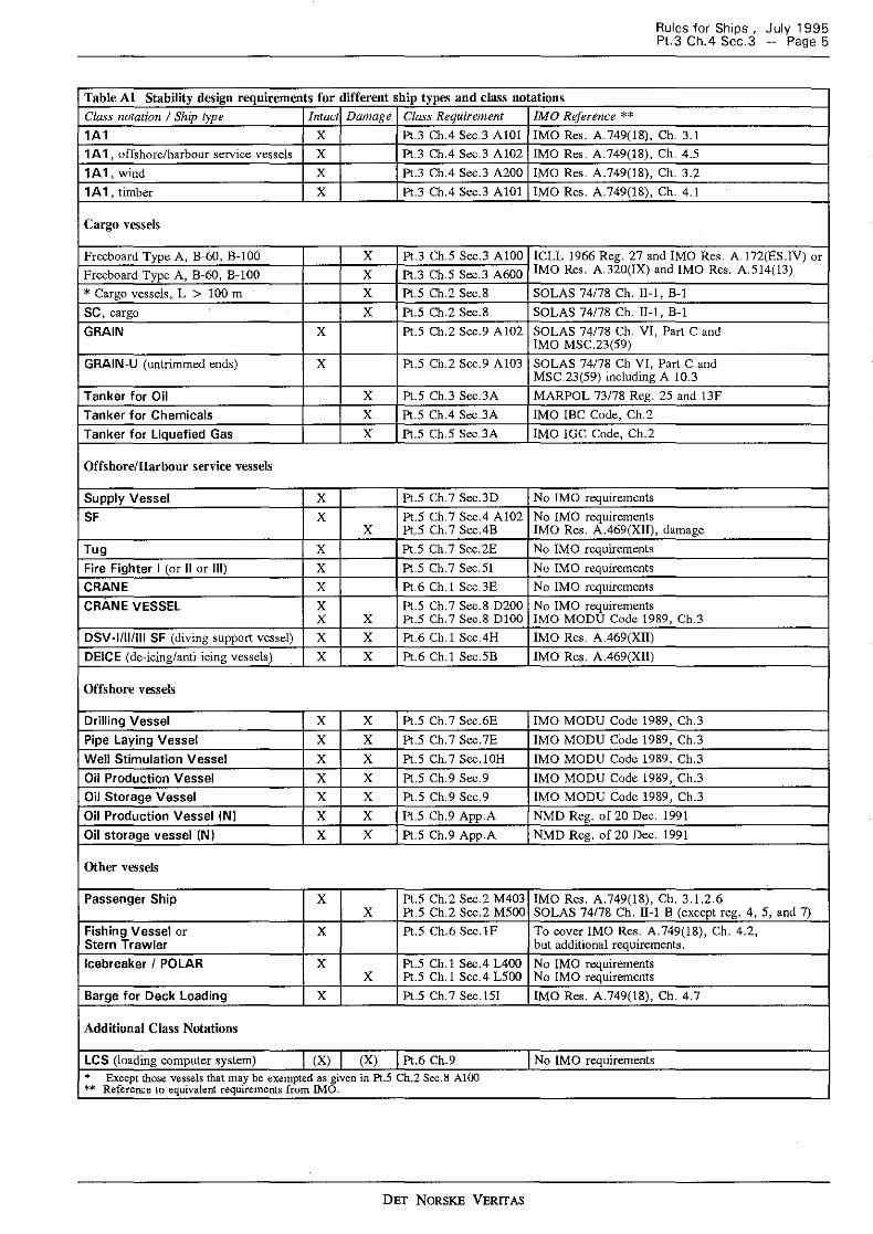
104 For certain ship types additional or alternative intact and damage stability criteria have been specified. These vessels (or class notations) are given in Table Al.
DET NORSKE VERITAS
Rules for Ships , July 1995 Pt.3 Ch.4 Sec.3 - Page 5
Table Al Stability design requirements for different ship types and class notations Class notation I Ship type Intact Damage Class Requirement IMO Reference ** 1A 1 x Pt.3 Ch.4 Sec.3 AIOI IMO Res. A. 749(18), Ch. 3.1
1A1 , offshore/harbour service vessels x Pt.3 Ch.4 Sec.3 A102 IMO Res. A.749(18), Ch. 4.5
1A1,wind x Pt.3 Ch.4 Sec.3 A200 IMO Res. A.749(18), Ch. 3.2
1A 1, timber x Pt.3 Ch.4 Sec.3 AIOI IMO Res. A.749(18), Ch. 4.1
Cargo vessels
Frecboard Type A, B-60, B-100 x Pt.3 Ch.5 Sec.3 AIOO ICLL 1966 Reg. 27 and IMO Res. A.172(ES.IV) or
Freeboard Type A, B-60, B-100 x Pt.3 Ch.5 Sec.3 A600 IMO Res. A.320(IX) and IMO Res. A.514(13)
* Cargo vessels, L > 100 m x Pt.5 Ch.2 Sec.8 SOLAS 74178 Ch. II-1, B-1
SC, cargo x Pt.5 Ch.2 Sec.8 SOLAS 74/78 Ch. II-I, B-1
GRAIN x Pt.5 Ch.2 Sec.9 A102 SOLAS 74178 Ch. VI, Part C and IMO MSC.23(59)
GRAIN-U (untrimmed ends) x Pt.5 Ch.2 Sec.9 AI03 SOLAS 74178 Ch VI, Part C and MSC.23(59) including A 10.3
Tanker for Oil x Pt.5 Ch.3 Sec.3A MARPOL 73/78 Reg. 25 and !3F
Tanker for Chemicals x Pt.S Ch.4 Sec.3A IMO !BC Code, Ch.2
Tanker for Liquefied Gas x Pt.S Ch.S Sec.3A IMO IGC Code, Ch.2
Offshore/Harbour service vessels
Supply Vessel x Pt.5 Ch. 7 Sec.3D No IMO requirements
SF x Pt.5 Ch. 7 Sec.4 A102 No IMO requirements x Pt.5 Ch. 7 Sec.4B IMO Res. A.469(Xll), damage
Tug x Pt.S Ch.7 Sec.2E No IMO requirements
Fire Fighter I (or II or Ill) x Pt.5 Ch.7 Sec.SI No IMO requirements
CRANE x Pt.6 Ch.! Sec.3E Na IM 0 requirements
CRANE VESSEL x Pt.5 Ch. 7 Sec. 8 D200 No IMO requirements x x Pt.5 Ch.7 Sec.8 DIOO IMO MODU Code 1989, Ch.3
DSV-1/111111 SF (diving support vessel) x x Pt.6 Ch. I Sec.4H IMO Res. A.469(XII)
DEICE (de-icing/anti icing vessels) x x Pt.6 Ch.! Sec.SB IMO Res. A.469(XII)
Offshore vessels
Drilling Vessel x x Pt.5 Ch. 7 Sec.6E IMO MODU Code 1989, Ch.3
Pipe Laying Vessel x x Pt.5 Ch. 7 Sec. 7E IMO MODU Code 1989, Ch.3
Well Stimulation Vessel x x Pt.5 Ch. 7 Sec. ! OH IMO MODU Code 1989, Ch.3
Oil Production Vessel x x Pt.S Ch.9 Sec.9 IMO MODU Code 1989, Ch.3
Oil Storage Vessel x x Pt.5 Ch.9 Scc.9 IMO MODU Code 1989, Ch.3
Oil Production Vessel (NI x x Pt.5 Ch.9 App.A NMD Reg. of 20 Dec. 1991
Oil storage vessel IN I x x Pt.5 Ch.9 App.A NMD Reg. of 20 Dec. 1991
Other vessels
Passenger Ship x Pt.S Ch.2 Sec.2 M403 IMO Res. A.749(18), Ch. 3.1.2.6 x Pt.5 Ch.2 Sec.2 MSOO SOLAS 74178 Ch. II-! B (except reg. 4, S, and 7)
Fishing Vessel or x Pt.S Ch.6 Sec. IF To cover IMO Res. A.749(18), Ch. 4.2, Stern Trawler but additional requirements.
Icebreaker I POLAR x Pt.5 Ch.! Sec.4 L400 No IMO requirements x Pt.5 Ch.! Sec.4 LSOO No IMO requirements
Barge for Deck Loading x Pt.5 Ch. 7 Sec. !SI IMO Res. A.749(18), Ch. 4.7
Additional Class Notations
LCS (loading computer system) (X) (X) Pt.6 Ch.9 No IMO requirements
• Except those vessels that may be exempted as given in Pt.5 Ch.2 Sec.8 AlOO "'"' Reference to equivalent requirements from IMO.
DET NORSKE VERITAS
Rules for Ships , July 1995 Page 6 - P1.3 Ch.4 Sec.3
A 200 Weather criterion
201 For ships with large windage area, such as passenger, container and Ro/Ro ships, the criteria listed below are to be complied with (based on IMO Res. A.749(18), Ch.3.2):
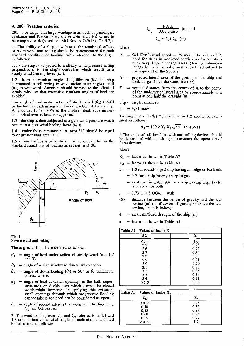
I The ability of a ship to withstand the combined effects of beam wind and rolling should be demonstrated for each standard condition of loading, with reference to the Fig. I as follows:
I. I - the ship is subjected to a steady wind pressure acting perpendicular to the ship's centreline which results in a steady wind heeling lever (lw1).
1.2 - from the resultant angle of equilibrium (8 0 ), the ship is assumed to roll owing to wave action to an angle of roll (81) to windward. Attention should be paid to the effect of steady wind so that excessive resultant angles of heel are avoided.
The angle of heel under action of steady wind (00 ) should be limited to a certain angle to the satisfaction of the Society. As a guide, 16° or 80% of the angle of deck edge immersion, whichever is less, is suggested.
1.3 - the ship is then subjected to a gust wind pressure which results in a gust wind heeling lever (lw,);
1.4 - under these circumstances, area "b" should be equal to or greater than area 11 a";
1.5 - free surface effects should be accounted for in the standard conditions of loading as set out in BIOO.
' ' ii; ~~ GZ ' '~ > ,~<>.b ,~, " ..J
~~' '~~\" lw, lw,
o, e, Oo Angle of heel
81
Fig. 1 Severe wind and rolling
The angles in Fig. I are defmed as follows:
80 = angle of heel under action of steady wind (see 1.2 and 3)
81 = angle of roll to windward due to wave action
82 angle of downflooding (Be) or 50° or 80 whichever is less, where:
Be angle of heel at which openings in the hull, superstructures or deckhouses which cannot be closed weathertight immerse. In applying this criterion, small openings through which progressive flooding cannot take place need not be considered as open.
Be = angle of second intercept between wind heeling lever lw2 and GZ curves.
2 The wind heeling levers lw1 and lw referred to in 1.1 and 1.3 are constant values at all angles ol inclination and should be calculated as follows:
PAZ 1w =----1 1000 g disp
(m)and
where:
P = 504 N/m2 (wind speed = 29 mis). The value of P, used for ships in restricted service and/or for ships with very large windage areas (due to coherence length for wind speed), may be reduced subject to the approval of the Society
A = projected lateral area of the portion of the ship and deck cargo above the waterline (m2)
Z vertical distance from the centre of A to the centre of the underwater lateral area or approximately to a point at one half the draught (m)
disp = displacement (t)
g = 9,81 m/s2
The angle of roll (81) * referred to in 1.2 should be calculated as follows:
81 = 109 k X1 X2 Fs (degrees)
* The angle of roll for ships with anti-rolling devices should be determined without taking into account the operation of these devices.
where:
X1 = factor as shown in Table A2
X2 = factor as shown in Table A3
k = 1,0 for round-bilged ship having no bilge or bar keels
= 0, 7 for a ship having sharp bilges
= as shown in Table A4 for a ship having bilge keels, a bar keel or both
r = 0, 73 ± 0,6 OG/d, with:
OG = distance between the centre of gravity and the waterline (m) ( + if centre of gravity is above the waterline, - if it is below)
d = mean moulded draught of the ship (m)
s = factor as shown in Table AS.
Table A2 Values of factor X Bid x, '.£2,4 1,0 2,5 0,98 2,6 0,96 2,7 0,95 2,8 0,93 2,9 0,91 3,0 0,90 3,1 0,88 3,2 0,86 3,3 0,84 3,4 0,82 ~3,5 0,80
Table A3 Values of factor X ch x?
'.£0,45 0,75 0,50 0,82 0,55 0,89 0,60 0,95 0,65 0,97
2'0,70 1,0
DET NORSKE VERITAS
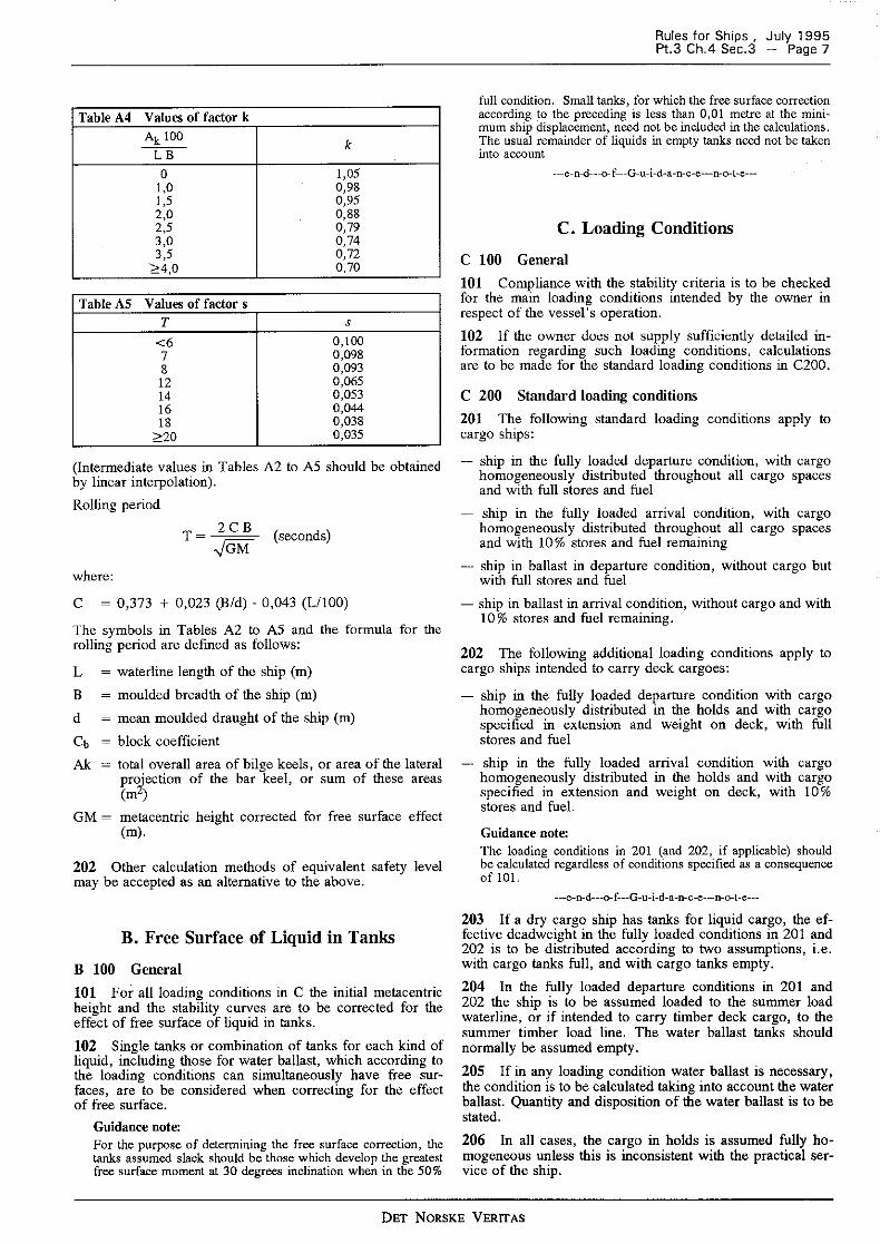
Table A4 Values of factor k
Ak 100 k ---
LB 0 1,05
1,0 0,98 1,5 0,95 2,0 0,88 2,5 0,79 3,0 0,74 3,5 0,72
'2::4,0 0,70
Table AS Values of factor s T s
<6 0,100 7 0,098 8 0,093 12 0,065 14 0,053 16 0,044 18 0,038
:2:20 0,035
(Intermediate values in Tables A2 to AS should be obtained by linear interpolation).
Rolling period
T = 2 CB (seconds) ../GM
where:
C = 0,373 + 0,023 (Bid) - 0,043 (L/100)
The symbols in Tables A2 to AS and the formula for the rolling period are defined as follows:
L = waterline length of the ship (m)
B = moulded breadth of the ship (m)
d = mean moulded draught of the ship (m)
Cb = block coefficient
Ak = total overall area of bilge keels, or area of the lateral pr~ection of the bar keel, or sum of these areas (m )
GM = metacentric height corrected for free surface effect (m).
202 Other calculation methods of equivalent safety level may be accepted as an alternative to the above.
B. Free Surface of Liquid in Tanks
B 100 General
101 For all loading conditions in C the initial metacentric height and the stability curves are to be corrected for the effect of free surface of liquid in tanks.
102 Single tanks or combination of tanks for each kind of liquid, including those for water ballast, which according to the loading conditions can simultaneously have free surfaces, are to be considered when correcting for the effect of free surface.
Guidance note: For the purpose of determining the free surface correction, the tanks assumed slack should be those which develop the greatest free surface moment at 30 degrees inclination when in the 50%
Rules for Ships , July 1995 Pt.3 Ch.4 Sec.3 - Page 7
full condition. Small tanks, for which the free surface correction according to the preceding is less than 0,01 metre at the minimum ship displacement, need not be included in the calculations. The usual remainder of liquids in empty tanks need not be taken into account
---e-n-d---o- f---G-u-i-d-a-n-c-e---n-o-t-e---
C. Loading Conditions
C 100 General
101 Compliance with the stability criteria is to be checked for the main loading conditions intended by the owner in respect of the vessel's operation.
102 If the owner does not supply sufficiently detailed information regarding such loading conditions, calculations are to be made for the standard loading conditions in C200.
C 200 Standard loading conditions
201 The following standard loading conditions apply to cargo ships:
- ship in the fully loaded departure condition, with cargo homogeneously distributed throughout all cargo spaces and with full stores and fuel
- ship in the fully loaded arrival condition, with cargo homogeneously distributed throughout all cargo spaces and with 10% stores and fuel remaining
- ship in ballast in departure condition, without cargo but with full stores and fuel
- ship in ballast in arrival condition, without cargo and with 10 % stores and fuel remaining.
202 The following additional loading conditions apply to cargo ships intended to carry deck cargoes:
- ship in the fully loaded departure condition with cargo homogeneously distributed in the holds and with cargo specified in extension and weight on deck, with full stores and fuel
- ship in the fully loaded arrival condition with cargo homogeneously distributed in the holds and with cargo specified in extension and weight on deck, with I 0 % stores and fuel.
Guidance note: The loading conditions in 201 (and 202, if applicable) should be calculated regardless of conditions specified as a consequence of 101.
---e-n-d---o-f---G-u-i-d-a-n-c-e---n-o-t-e---
203 If a dry cargo ship has tanks for liquid cargo, the effective deadweight in the fully loaded conditions in 201 and 202 is to be distributed according to two assumptions, i.e. with cargo tanks full, and with cargo tanks empty.
204 In the fully loaded departure conditions in 20 I and 202 the ship is to be assumed loaded to the summer load waterline, or if intended to carry timber deck cargo, to the summer timber load line. The water ballast tanks should normally be assumed empty.
205 If in any loading condition water ballast is necessary, the condition is to be calculated taking into account the water ballast. Quantity and disposition of the water ballast is to be stated.
206 In all cases, the cargo in holds is assumed fully homogeneous unless this is inconsistent with the practical service of the ship.
DET NORSKE VERITAS
Rules for Ships , July 1995 Page 8 - Pt.3 Ch.4 Sec.3
207 Where timber deck cargoes are carried, the amount of cargo and ballast is to correspond to the worst service condition in which all the stability criteria in AlOO are met. In the arrival condition it is to be assumed that the weight of the deck cargo has increased by 10 % due to water absorption.
208 In all cases, when deck cargo is carried, a realistic stowage weight is to be assumed and stated, including the height of the cargo.
Guidance note: For ships carrying timber deck cargoes conditions should be shown indicating the maximum permissible amount of deck ~rgo ~aving regard to the lightest stowage rate likely to be met in service.
---e-n-d---o-f---G-u-i-d-a-n-c-e---n-o-t-e---
D. Calculation of Stability
D 100 General
101 Hydrostatic and stability curves (cross curves of stability) are normally to be prepared on a designed trim basis. However, where the operating trim or the form and arrangement of the ship are such that change in trim has an appreciable effect on the hydrostatics or the stability curves, the hydrostatics or the stability curves are to be prepared for the intended range of operating trim. Calculation of stability curves is to be done on a free to trim basis.
D 200 Deckhouses and superstructures
201 Enclosed superstructures complying with Pt.3 Ch. I Sec. I B212 b) may be taken into account.
202 The second tier of similarly enclosed superstructures may also be taken into account.
203 Deckhouses on the freeboard deck may be taken into account, provided that they comply with the conditions for enclosed superstructures.
204 Where deckhouses comply with 203, except that no additional exit is provided to a deck above, such deckhouses are not to be taken into account. However, any opening inside such deckhouses are to be considered as closed even where no means of closure are provided.
205 Deckhouses, the doors of which do not comply with Pt.3 Ch.I Sec.II BIOi, is not to be taken into account. However, any deck openings inside the deckhouse are regarded as closed if their means of closure comply with Pt.3 Ch.I Sec.II B301 orPt.3 Ch.I Sec.II J 100.
206 Deckhouses on decks above the freeboard deck are not to be taken into account, but openings within them may be regarded as closed.
207 Superstructures and deckhouses not regarded as enclosed can, however, be taken into account in stability calculations up to the angle at which their openings are flooded. At this angle, the stability curve should show one or more steps, and in subsequent computations the flooded space is to be considered non-existent.
208 In cases where the ship would sink due to flooding through any openings, the stability curve is to be cut short at the corresponding angle of flooding, and the ship is to be considered to have entirely lost its stability.
209 Small openings such as those for passing wires or chains, tackle and anchors, and also holes of scuppers, discharge and sanitary pipes need not be considered as open if they submerge at an angle of inclination more than 30°. If they submerge at an angle of 30° or less, these openings are to be assumed open if they in the opinion of the Society can be considered as source of significant flooding.
210 Trunks may be taken into account. Hatchways may also be taken into account provided they have efficient closure.
D 300 Effect of timber deck cargo
301 The Society may allow account to be taken in stability calculations of the buoyancy of the deck cargo assuming that such cargo has a permeability of 0,25.
E. Damage Stability of Cargo Ships
E 100 Application
101 Cargo ships over 100 min length are to comply with the damage stability requirements in Pt.5 Ch.2 Sec.8, except those vessels which may be exempted in accordance with Pt.5 Ch.2 Sec.8 AIOI.
DET NORSKE VERITAS
Rules for Ships , July 1995 Pt.3 Ch.4 Sec.4 - Page 9
SECTION 4 WATERTIGHT INTEGRITY
Contents
A. General A 100 General
A. General
A 100 General
101 Openings in the shell, exposed decks and in enclosed superstructures and deckhouses which have been taken into account in the stability calculations, are to have closing appliances which comply with the requirements of Ch.2 Sec.! I if the opening may become submerged at an angle of heel less than the dynamic angle.
102 Regulation 23-1 Damage control in dry cargo ships
1 There shall be permanently exhibited or readily available on the navigating bridge, for the guidance of the officer in charge of the ship, a plan showing clearly for each deck and hold the boundaries of the watertight compartments, the
openings therein with the means of closure and position of any controls thereof, and the arrangements for the correction of any list due to flooding. In addition, booklets containing the aforementioned information shall be made available to the officers of the ship.
2 Indicators shall be provided for all sliding doors and for hinged doors in watertight bulkheads. Indication showing whether the doors are open or closed shall be given on the navigating bridge. In addition, shell doors and other openings which, in the opinion of the Administration, could lead to major flooding if left open or not properly secured, shall be provided with such indicators.
3. 1 General precautions shall consist of a listing of equipment, conditions and operational procedures, considered by the Administration to be necessary to maintain watertight integrity under normal ship operations.
3. 2 Specific precautions shall consist of a li'sting of elements (i.e. closures, security of cargo, sounding of alarms, etc.) considered by the Administration to be vital to the survival of the ship and its crew.
103 The additional indicators and the listing of equipment and elements as prescribed in 102 will be considered by the Society in each case.
DET NORSKE VERITAS
Rules for Ships , July 1995 Page 10 - Pt.3 Ch.4 Sec.5
SECTION 5 DETERMINATION OF LIGHTWEIGHT DATA
A. Inclining Test A 100 Application A 200 Procedure
B. Lightweight Survey B 100 Application B 200 Procedure
Contents
A. Inclining Test
A 100 Application
101 Every passenger ship and cargo ship is to be inclined upon its completion and the lightweight displacement and centre of gravity determined.
102 The inclining test required in IOI may be dispensed with provided basic stability data are available from the inclination test of a sister ship and it is shown to the satisfaction of the Society that reliable stability information for the exempted ship can be obtained from such basic data.
Guidance note: Dispensation according to 102 is not considered applicable to passenger ships and other ships where the lightweight is more than 75 % of the total displacement.
---e-n-d---o-f---G-u-i-d-a-n-c-e---n-o-t-e--
A 200 Procedure
201 The inclining test is to be carried out according to the approved test pruc~dure and in the presence of the Society's representative.
Guidance note: Guidelines for conducting inclining test or lightweight survey are given in Classification Note No. 20.2 «Lightweight Determination - Ships•.
---e-n-d---o-f---G-u-i-d-a-n-c-e---n-o-t-e---
202 The inclining test report is to be signed by the person responsible for the test and by the Society's representative.
203 The lightweight displacement and the centre of gravity obtained by the inclining test are to be used in the final stability booklet.
B. Lightweight Survey
B 100 Application
101 A lightweight survey is to be carried out if an inclining test has been dispensed with according to Al02.
102 Jn case structural strength limitations etc. make it impossible to perform an inclining test, a lightweight survey may be accepted provided a detailed lightweight estimate including V CG is worked out in advance and the estimate compared with the result of the lightweight survey. If the lightweight survey reveals a deviation of lightweight data from the estimate, the deviation is to be assumed at the most unfavourable position when calculating the vertical centre of gravity.
B 200 Procedure
201 The lightweight survey is to be carried out according to the approved test procedure and in the presence of the Society's representative.
Guidance note: Guidelines for conducting the lightweight survey are given in Classification Note No. 20.2 «Lightweight Determination Ships•
--e-n-d---o-f---G-u-i-d-a-n-c-e---n-o-t-e--
202 The lightweight survey report is to be signed by the person responsible for the test and by the Society's representative.
203 If, compared with the sister ship, the lightweight survey reveals a lightweight displacement deviation exceeding 2 % or an LCG deviation exceeding I % of the length of the ship, an inclining test may be required.
204 The lightweight displacement and the longitudinal centre of gravity obtained by the lightweight survey are to be used in the final stability booklet. If the lightweight displacement deviation is less than 0,5 % , the VCG of the sistership may be used, otherwise the VCG must be corrected assuming the weight deviation at the most unfavourable position.
DET NORSKE VERITAS