Embed Size (px)
Citation preview
SSttrriikkeerr EEL 4914 Senior Design I
Group 8
Cruz, Efrain Decamp, Loubens
Narvaez, Luis Thomas, Brian
Competitive Autonomous Air-Hockey Gaming system

i
Table of Contents
Table of Contents .................................................................................................. i
1 Executive Summary .......................................................................................... 1
2 Project Description ............................................................................................ 3
2.1 Motivation ................................................................................................................. 3
2.2 Goals and Objectives ................................................................................................. 4
2.3 Requirements and Specifications ........................................................................... 4
2.3.1 User Interface .................................................................................................... 4
2.3.2 Audio and Visual Effects .................................................................................... 6
2.3.3 Tracking System ................................................................................................. 7
2.3.4 Software .............................................................................................................. 9
2.3.5 System Hardware .............................................................................................. 10
2.3.6 Puck Return Mechanism ................................................................................... 11
2.3.7 Communication ................................................................................................ 12
3 Research ......................................................................................................... 13
3.1 Existing Technology and Products .......................................................................... 13
3.2 Puck Position Tracking System .............................................................................. 13
3.2.1 XBOX360 Kinect ............................................................................................. 14
3.2.2 CMUcam .......................................................................................................... 15
3.2.2.1 CMUcam Software ........................................................................................ 17
3.2.2.2 Pixy Hardware Interface ................................................................................ 20
3.2.3 Communication ................................................................................................ 21
3.3 Puck Return Mechanism ......................................................................................... 22
3.3.1 Design Overview .............................................................................................. 22
3.3.2 Goal Sensors ..................................................................................................... 22
3.3.3 Motor for Conveyor Belt .................................................................................. 30
3.3.4 Interfacing with a Microcontroller ................................................................... 33
3.4 Robot Arm ............................................................................................................... 34
3.4.1 Design Overview .............................................................................................. 34
3.4.2 Processor ........................................................................................................... 34
3.4.3 Communication from Position Tracker ............................................................ 34
3.4.4 Hardware .......................................................................................................... 35
ii
3.4.5 Software ............................................................................................................ 43
3.5 Air Hockey Table .................................................................................................... 44
3.5.1 Harvard Action Arena 7’ Air Hockey Table .................................................... 44
3.6 Audio System .......................................................................................................... 44
3.6.1 Speakers ............................................................................................................ 44
3.6.2 Audio Controller ............................................................................................... 44
3.7 Video System .......................................................................................................... 46
3.7.1 Cameras ............................................................................................................ 48
3.7.2 Display Monitor ................................................................................................ 49
3.7.3 Video Controller ............................................................................................... 49
3.7.4 Graphics for Display Monitor........................................................................... 54
3.7.5 LED Strip Lighting ........................................................................................... 54
3.8 Communication System .......................................................................................... 58
Table 12 – Wireless Communication System Comparisons ............................... 58
3.8.1 Bluetooth .......................................................................................................... 59
Table 13 - Bluetooth Power Classes .................................................................. 59
3.8.2 Wireless Fidelity (Wi-Fi) .................................................................................. 61
3.8.3 Zigbee ............................................................................................................... 61
3.8.4 Interfacing with System Controllers ................................................................. 61
3.8.3 Software ............................................................................................................ 66
3.9 System Microcontroller ........................................................................................... 66
3.9.1 T.I. MSP430FG4618 ........................................................................................ 66
3.9.2 Arduino ............................................................................................................. 67
3.9.2 I/O Assignments ............................................................................................... 69
3.9.3 Communication to User Interface ..................................................................... 71
3.10 PCB ....................................................................................................................... 71
3.11 Power Supply ........................................................................................................ 72
3.11.1. Transformer ................................................................................................... 72
3.11.2 Voltage Regulator ........................................................................................... 74
3.12 User Interface ........................................................................................................ 75
3.12.1 Android ........................................................................................................... 75
3.12.2 iOS .................................................................................................................. 76
3.12.3 Windows Phone .............................................................................................. 76
iii
3.12.4 Receiving Data From Striker .......................................................................... 76
4 Design Summary of Hardware and Software .................................................. 77
4.1 System Overview .................................................................................................... 77
4.2Wireless Communication ......................................................................................... 80
4.3 Puck Tracking System ............................................................................................. 82
4.4 Visual Display ......................................................................................................... 88
4.4.1 Hardware .......................................................................................................... 88
4.5 Software Design ...................................................................................................... 90
4.6 Goal Sensors ............................................................................................................ 94
4.7 Power Supply .......................................................................................................... 95
4.8 Robot Arm ............................................................................................................... 96
4.9 Puck-Return ............................................................................................................. 98
100384908 ..................................................................................................................... 99
5 Prototype and Testing ................................................................................... 100
5.1 Puck Tracking (Pixy) ............................................................................................ 100
5.1.1 Coordinate Test............................................................................................... 100
5.1.2 Trajectory Test ................................................................................................ 101
5.1.3 SPI Communication Test ................................................................................ 102
5.2 Bluetooth ............................................................................................................... 102
5.2.1 Wireless connectivity test ............................................................................... 103
5.2.2 Wireless Control Test ..................................................................................... 104
5.3 Robotic Arm .......................................................................................................... 105
5.3.1 Stepper Motor ................................................................................................. 105
5.3.2 Servomotor Test ............................................................................................. 105
5.4 Arduino Uno .......................................................................................................... 106
5.4.1 Lights Test ...................................................................................................... 106
5.4.2 Goal Sensor Tests ........................................................................................... 107
5.4.3 Puck Return Test ............................................................................................ 108
5.4.4 UART/SPI Communication Testing ............................................................... 109
5.4.5 System Test..................................................................................................... 110
5.5 Davinci Test Procedures........................................................................................ 111
5.5.1 Audio/Video Test ........................................................................................... 111
5.5.2 LED Strip Test ................................................................................................ 112
iv
5.6 Power Supply ........................................................................................................ 114
5.6.1 Transformer Testing ....................................................................................... 114
5.6.2 Complete System Power ................................................................................. 114
6 Administrative Content .................................................................................. 116
6.1 Milestone Discussion ............................................................................................ 116
6.2 Budgeting and Finance .......................................................................................... 118
6.3 Sponsors and Contributors .................................................................................... 121
Appendix A – Permissions ............................................................................... 122
Appendix B – Figures and Tables Index ........................................................... 142
Appendix C – Works Cited ............................................................................... 145
1
1 Executive Summary
Three engineers from Brunswick Billiards consisting of Phil Crossman, Bob Kenrick, and Brad Baldwin began work on a project in 1969 for a game that would utilize a frictionless playing surface. Their game would be developed over the next three years. However, interest in the project waned and it was set aside. Fortunately, Bob Lemieux resurrected the project and refocused the design to simulate ice hockey. The table surface would be comprised of tiny holes that would supply air to the surface as a method of making the playing surface frictionless. The objective was to direct small discs to your opponent’s goal that was comprised of a slit at the end of the table, which incorporated photo sensors to monitor scoring. Mallets were used to strike the disc as a means of propulsion. This exciting new game would be branded as Air Hockey and produced to the public. Air Hockey was a meteoric success and was subsequently a financial achievement during the mid 1970’s. Forty years later, Air Hockey is still relevant in most gaming facilities. [1]
Striker represents air hockey re-imagined for the avid player. The premise is that a human player plays its counterpart in the form of an autonomous robot that will have multiple playing difficulties to challenge all skill levels who play Striker. The gamer will have the option of selecting particular playing difficulties by virtue of a smart phone application, which will also monitor a person’s progress, record statistics, store instant replays and rank a player’s success against other participants. Wireless communication to the smart phone incorporating the device’s operating system will be accomplished by means of wireless communication. In addition, there will be visual and audio alerts based on goals scored and games won by either the human or autonomous robot. There will be two ways to win the game. The first way, as with traditional air hockey, the first opponent to score seven goals wins the game. The second way is to outscore the robot in a timed game.
Control of the autonomous robot will be accomplished via electronic controller and the tracking of the puck using various software algorithms. The table will be augmented to incorporate a puck return system that will consist of motors and belts. Other features for the table will include a display to show game time, score and other various statistics. Furthermore, the display will be suspended above the air rink to immerse the player in the ultimate air hockey gaming experience. The monitor will act as a mini “jumbo-tron” to show replays of goals scored along with aesthetic effects to illustrate games won.
The robot design consists of a horizontal and vertical translation. This design was intended to be simplistic in nature to reduce error in tracking of the puck. The base of the robot will travel from side to side on a fixed rail system. The base has two sets of casters on either side that are affixed to the rail and will function much

2
like a trolley system. A belt and pulley system along with a motor will provide the means of propulsion. Vertical translation will function in a similar fashion with a solenoid instituted at the end effector to generate instantaneous movement to strike the puck.
Striker will represent many aspects of electrical engineering design. Conceivably the biggest challenge will be the tracking of the puck and the appropriate response time by the robot.
3
2 Project Description
2.1 Motivation
The basic motivation towards completion of this project is to further develop our skill with electrical and computer engineering principles. As a group of electrical engineers, we have come to acquire numerous amounts of academic knowledge in the fields of circuit theory, power systems, and computer programming. With the trends of technology becoming more about personal technologies, as in technologies that are geared towards individual solutions, it is important as modern engineers to have the ability to gear our knowledge towards unique and innovative solutions.
The autonomous air hockey itself is not a new idea. A basic search online confirms that others have attempted to create this project with success. Our solution, however, will be unique in part because of our motivation to develop our electrical engineering skills. It is obvious that this project will require a power source, voltage regulators, actuators, sensors, and much more. The question that drives us is, how do we put these technologies together to meet the needs of our project? There are additional questions that follow. How will our knowledge in circuit theory and power systems guarantee that the devices we use work within an efficient and operational mode? How do we interface the technologies to look like one streamlined object that is appealing to the participant without over whelming their senses?
There are many basic technologies and principles that academia has educated us on: resistors, capacitors, diodes, operational amplifiers, integrated circuits, motors, and servos to name a few. We have learned how these devices behave along with the formulation model to predict behavior. However, there is only so much academia can teach us. A project of this nature will allow us to learn about technologies that are not part of our curriculum. By doing so, it will allow us to further improve the fundamental principles that we have acquired, by allowing us to exercise our skills on newly created technologies. The challenges we face will be the strengths we gain.
Another driving force is gaining advanced programming skills, a fundamental skill of computer engineering. The Air Hockey Table will require artificial intelligence. Although we have basic knowledge of programming microcontrollers, a project in this nature requires specialized skills. In the process of completing this project, we will acquire knowledge on various programming languages, various software, and wireless technologies. Wireless technologies are also a trend that has been evolving in technology. Wireless devices are not only becoming more popular, but are becoming a preference in personal technologies.
4
With the knowledge that we gain from creating this project, we believe we will possess the skills that are required and sought after in the engineering community of today. It will allow us to prove our understanding of electrical and computer engineering, while creating an innovative product that is fun and follows the current technological trends. It will give us the advantage of proving that we can apply academic knowledge to real life projects.
2.2 Goals and Objectives
The goal of this project is to create an Autonomous Air Hockey Table that is more engaging than traditional air hockey tables are. The Air Hockey experience that we create should mimic that of an arcade game experience. After scoring against the robotic opponent sounds will play, lights will flash, and an instant replay will play on a screen. Afterwards, a puck return mechanism, driven by motors and belts, will direct the puck back to the player. The screen used to play instant replays will also display time, score, and various statistics. When the player wins, different lights and sounds play, compared to a regular goal scored, signaling a victory and the end of the game.
Before the game begins, the player will have the ability to choose a difficulty level through a smart phone application. The difficulty levels will affect reaction time for the robotic arm. The reaction time is directly proportional to the difficulty level chosen by the user. Additionally, the player will create a profile so that their score may be saved and compared with others. As the game occurs, the camera and other sensors will record data. These data will be analyzed and will be used to give the player various statistics about the game played. This data will be available to be seen on a phone application. This phone application will also have access to the replays and will give the player the ability to save and forward the replays.
2.3 Requirements and Specifications
The specifications and requirements for the main system components are critical to the research phase of making a design. In this section, we break down critical components to determine the specifications required for their individual purpose. These specifications will be used as a basis for our research relating to the project definition.
2.3.1 User Interface
With our project being one of interaction, it was imperative to define the user’s role in the experience. One way to integrate the user with the system is to develop and application. This application will have various features to control the game and interact with Striker.
5
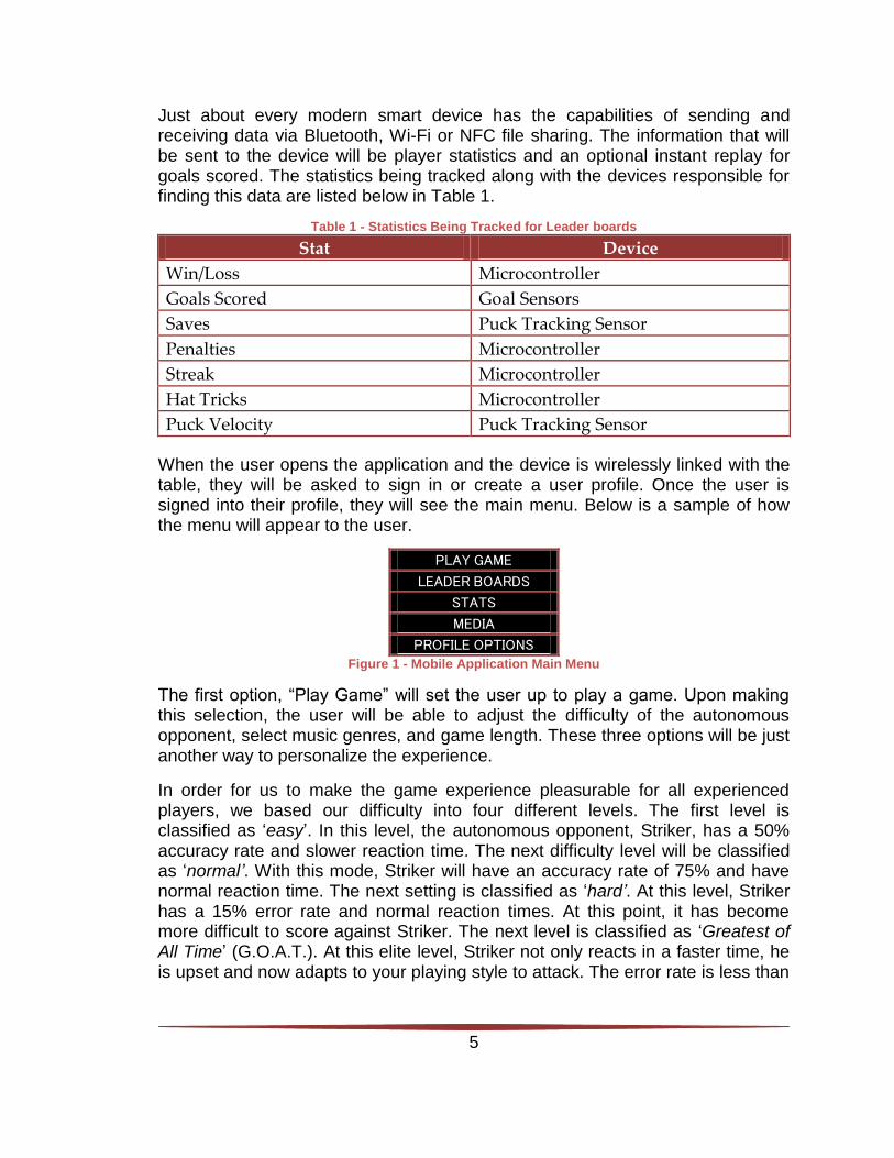
Just about every modern smart device has the capabilities of sending and receiving data via Bluetooth, Wi-Fi or NFC file sharing. The information that will be sent to the device will be player statistics and an optional instant replay for goals scored. The statistics being tracked along with the devices responsible for finding this data are listed below in Table 1.
Table 1 - Statistics Being Tracked for Leader boards
Stat Device
Win/Loss Microcontroller
Goals Scored Goal Sensors
Saves Puck Tracking Sensor
Penalties Microcontroller
Streak Microcontroller
Hat Tricks Microcontroller
Puck Velocity Puck Tracking Sensor
When the user opens the application and the device is wirelessly linked with the table, they will be asked to sign in or create a user profile. Once the user is signed into their profile, they will see the main menu. Below is a sample of how the menu will appear to the user.
PLAY GAME
LEADER BOARDS
STATS
MEDIA
PROFILE OPTIONS
Figure 1 - Mobile Application Main Menu
The first option, “Play Game” will set the user up to play a game. Upon making this selection, the user will be able to adjust the difficulty of the autonomous opponent, select music genres, and game length. These three options will be just another way to personalize the experience.
In order for us to make the game experience pleasurable for all experienced players, we based our difficulty into four different levels. The first level is classified as ‘easy’. In this level, the autonomous opponent, Striker, has a 50% accuracy rate and slower reaction time. The next difficulty level will be classified as ‘normal’. With this mode, Striker will have an accuracy rate of 75% and have normal reaction time. The next setting is classified as ‘hard’. At this level, Striker has a 15% error rate and normal reaction times. At this point, it has become more difficult to score against Striker. The next level is classified as ‘Greatest of All Time’ (G.O.A.T.). At this elite level, Striker not only reacts in a faster time, he is upset and now adapts to your playing style to attack. The error rate is less than
6
10% and is nearly impossible to beat. After the difficulty level is adjusted to the player’s desire, the next option is music.
At this point, the user has a couple choices in regards to music during game play. They can choose to select a genre of music from a list, or to create a playlist from the library. Furthermore, the user will then have to specify the game type. There will be two different game types to select from – ‘First-to-score’ and ‘full game’. The ‘full game’ will consist of 3 periods at 5 minutes each. First-to-score is a game type where the user specifies the goal limit, within a given range, necessary to win.
For the leader boards, the user can check their rankings against other players who have played the system. They can also compare stats and sort them accordingly. The ‘Stats’ menu option allows users to check their stats and observe their progression as they continue to play. If they choose not to view their stats, they have the option of viewing saved media from previous games.
The media being saved onto the device would be instant replays. When a goal is scored, the user has 10 seconds to respond on whether they want to save the instant replay or not. If they decline or refuse to respond within this time, the video gets lost forever. The instant replay will show the scoring goal.
2.3.2 Audio and Visual Effects
The audio and visual system will be separate from the main control system. The Audio and video controllers will be controlled in which command signals to the MCU or FPGA will be sent from the main system controller. We want to use a separate controller in order to take off some of the computation from the main system’s microcontroller. In order for our video data to consistently project, the microcontroller would be running continuous data from the video camera, in which would slow down our system response due to the high data rate required for visual effects alone.
7
Game Sens o r s
System
Microcontroller A/V Control MCU
Audio Controller Video Controller
System DataAudio/Video
Command
Audio
Data
Digital Video
Data
Speakers Display Monitor
Audio Signal Video Signal
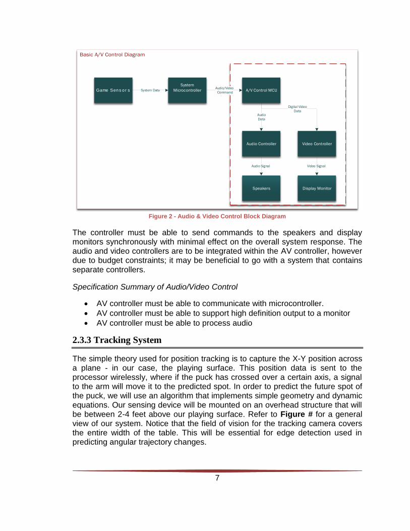
Figure 2 - Audio & Video Control Block Diagram
The controller must be able to send commands to the speakers and display monitors synchronously with minimal effect on the overall system response. The audio and video controllers are to be integrated within the AV controller, however due to budget constraints; it may be beneficial to go with a system that contains separate controllers.
Specification Summary of Audio/Video Control
AV controller must be able to communicate with microcontroller.
AV controller must be able to support high definition output to a monitor
AV controller must be able to process audio
2.3.3 Tracking System
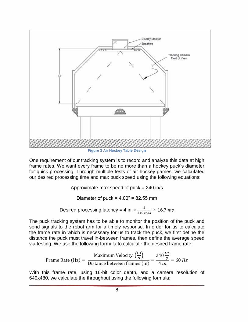
The simple theory used for position tracking is to capture the X-Y position across a plane - in our case, the playing surface. This position data is sent to the processor wirelessly, where if the puck has crossed over a certain axis, a signal to the arm will move it to the predicted spot. In order to predict the future spot of the puck, we will use an algorithm that implements simple geometry and dynamic equations. Our sensing device will be mounted on an overhead structure that will be between 2-4 feet above our playing surface. Refer to Figure # for a general view of our system. Notice that the field of vision for the tracking camera covers the entire width of the table. This will be essential for edge detection used in predicting angular trajectory changes.
8
Figure 3 Air Hockey Table Design
One requirement of our tracking system is to record and analyze this data at high frame rates. We want every frame to be no more than a hockey puck’s diameter for quick processing. Through multiple tests of air hockey games, we calculated our desired processing time and max puck speed using the following equations:
Approximate max speed of puck = 240 in/s
Diameter of puck = 4.00” = 82.55 mm
Desired processing latency = 4 in
The puck tracking system has to be able to monitor the position of the puck and send signals to the robot arm for a timely response. In order for us to calculate the frame rate in which is necessary for us to track the puck, we first define the distance the puck must travel in-between frames, then define the average speed via testing. We use the following formula to calculate the desired frame rate.
( ) (
)
( )
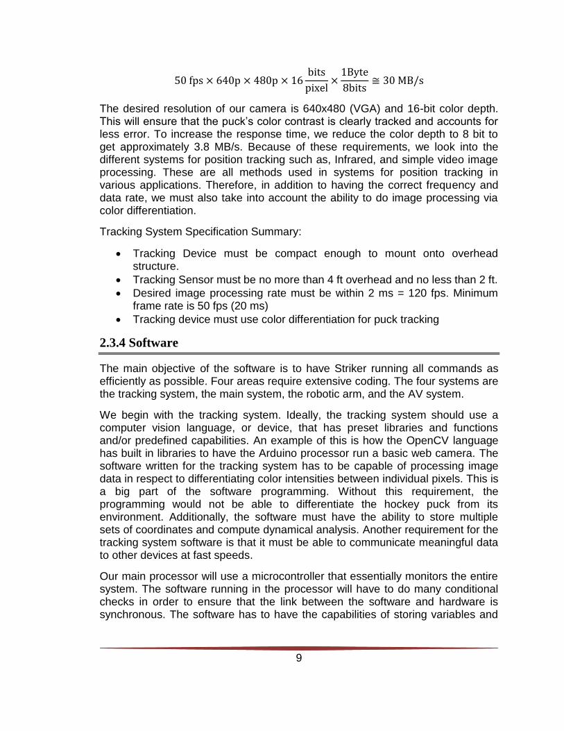
With this frame rate, using 16-bit color depth, and a camera resolution of 640x480, we calculate the throughput using the following formula:
9
The desired resolution of our camera is 640x480 (VGA) and 16-bit color depth. This will ensure that the puck’s color contrast is clearly tracked and accounts for less error. To increase the response time, we reduce the color depth to 8 bit to get approximately 3.8 MB/s. Because of these requirements, we look into the different systems for position tracking such as, Infrared, and simple video image processing. These are all methods used in systems for position tracking in various applications. Therefore, in addition to having the correct frequency and data rate, we must also take into account the ability to do image processing via color differentiation.
Tracking System Specification Summary:
Tracking Device must be compact enough to mount onto overhead structure.
Tracking Sensor must be no more than 4 ft overhead and no less than 2 ft.
Desired image processing rate must be within 2 ms = 120 fps. Minimum frame rate is 50 fps (20 ms)
Tracking device must use color differentiation for puck tracking
2.3.4 Software
The main objective of the software is to have Striker running all commands as efficiently as possible. Four areas require extensive coding. The four systems are the tracking system, the main system, the robotic arm, and the AV system.
We begin with the tracking system. Ideally, the tracking system should use a computer vision language, or device, that has preset libraries and functions and/or predefined capabilities. An example of this is how the OpenCV language has built in libraries to have the Arduino processor run a basic web camera. The software written for the tracking system has to be capable of processing image data in respect to differentiating color intensities between individual pixels. This is a big part of the software programming. Without this requirement, the programming would not be able to differentiate the hockey puck from its environment. Additionally, the software must have the ability to store multiple sets of coordinates and compute dynamical analysis. Another requirement for the tracking system software is that it must be able to communicate meaningful data to other devices at fast speeds.
Our main processor will use a microcontroller that essentially monitors the entire system. The software running in the processor will have to do many conditional checks in order to ensure that the link between the software and hardware is synchronous. The software has to have the capabilities of storing variables and
10
carrying out calculations. It has to be able to provide and use communication protocols such as RS232, Zigbee, and Wi-Fi.
Another system that has software requirements will be the robotic arm. The robotic arm and the AV systems have similar requirements as the main processors microcontroller. An addition to the requirements for the robotic arms software is that it must be able to provide pulse width commands to run motors, servos, or any other actuator devices.
2.3.5 System Hardware
Robotic System
One important requirement for Striker is to be able to make movements quickly, primarily across a single axis (Prismatic). These quick movements will be implemented using a single motor with a belt driving the end-effector. The end-effector will have a smaller tilt motor to position the mallet for striking back.
Another constraint to consider when designing our robot arm is the weight of the end-effector, which can inhibit our velocity. We must also specify the track system being used. We want a track that is durable, and allows caster wheels to move with limited loss in friction. In total, the process of the controller sending a signal to the servo and the servo moving must happen within 20 milliseconds.
System Controller
For our main system controller, we want a controller to give us a fast response to sensor input signals, as well as quick processing for data. Our main controller will be either FPGA or MCU. The inputs read by the main controller will be mostly from in-game sensors, wireless communication and video signals.
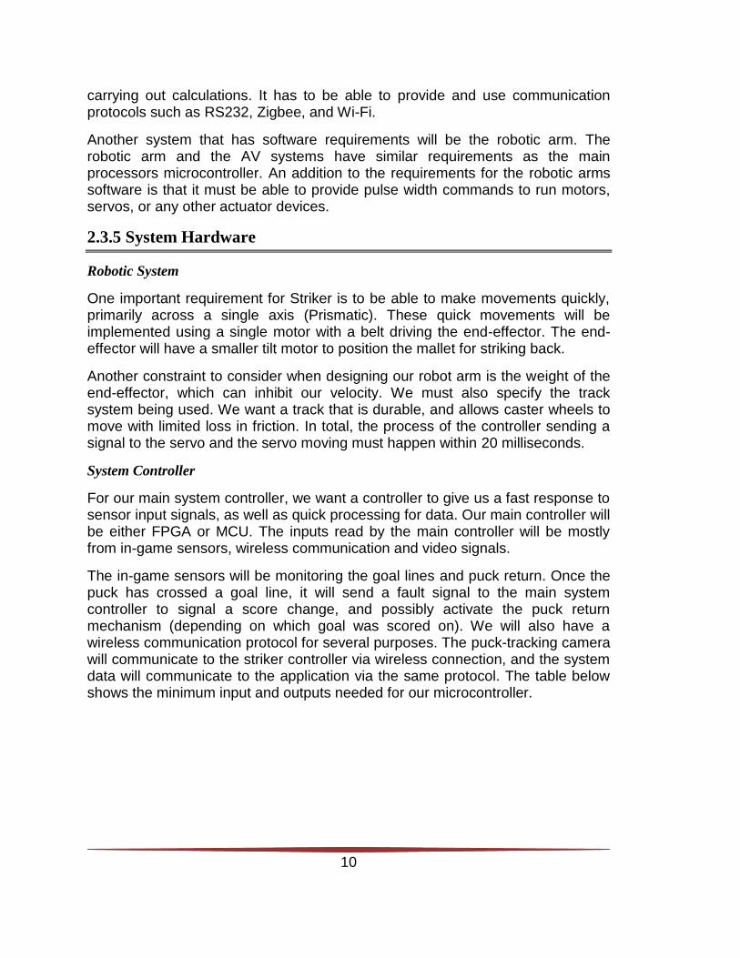
The in-game sensors will be monitoring the goal lines and puck return. Once the puck has crossed a goal line, it will send a fault signal to the main system controller to signal a score change, and possibly activate the puck return mechanism (depending on which goal was scored on). We will also have a wireless communication protocol for several purposes. The puck-tracking camera will communicate to the striker controller via wireless connection, and the system data will communicate to the application via the same protocol. The table below shows the minimum input and outputs needed for our microcontroller.
11
Table 2 - Microcontroller Monitored I/O
Monitored Data Input/ Output Input Output
UART (Monitor User Input from Bluetooth/App) Yes Yes
Goal Sensors Yes Yes
AV Yes Yes
Puck Return Mechanism Motors No Yes
Game LED Lighting No Yes
In-game Camera Yes Yes
Power Supply Yes No
Minimum Device Pins 4 6
Specification Summary of System Hardware:
Motor must rotate at high rpm to achieve desired linear velocity
System controller must have a minimum of 6 output pins, and 4 input pins.
System Controller must have communication interfacing compatible with wireless communication devices (i.e. USB, UART, I2C, and SPI.)
2.3.6 Puck Return Mechanism
The puck return mechanism has to be able to receive signal from the goal sensors. As mentioned previously, once a goal is scored against Striker, the sensors within the goal will send a signal to the main microcontroller discussed in 2.3.5. This signal will then trigger a successive command to the motor for the puck return mechanism. This mechanism has to be able to send the puck back to the user without having the user move from their position.
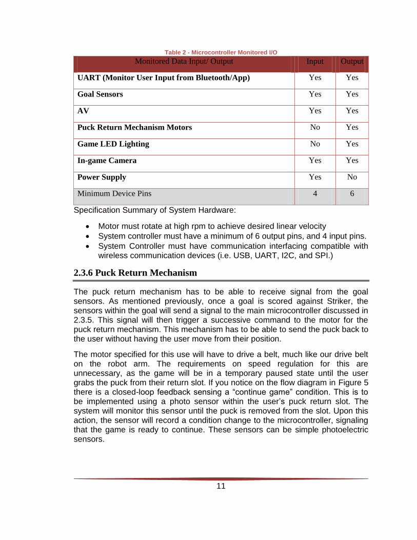
The motor specified for this use will have to drive a belt, much like our drive belt on the robot arm. The requirements on speed regulation for this are unnecessary, as the game will be in a temporary paused state until the user grabs the puck from their return slot. If you notice on the flow diagram in Figure 5 there is a closed-loop feedback sensing a “continue game” condition. This is to be implemented using a photo sensor within the user’s puck return slot. The system will monitor this sensor until the puck is removed from the slot. Upon this action, the sensor will record a condition change to the microcontroller, signaling that the game is ready to continue. These sensors can be simple photoelectric sensors.
12
Puck Return Flow Diagram
Sensor see puck? Yes
Motor
BeltReturn Puck
To user
Game continue?
No
Power Switch
yes
No
Figure 4: Puck Return Flow Diagram
Specification Summary of the Puck Return Mechanism
Has to return puck on command
Has to provide enough friction to transport the puck
2.3.7 Communication
The communication protocol in our system is as critical to our project as any other device. Our system will take advantage of several communication methods, including wired and wireless. Our wireless system will communicate between several systems including the puck-tracking system, the main processor and a smart phone running an application that interfaces with Striker. Our main requirements for the wireless communication are that it has to be low power, efficient, and have fast response. Our fast response is desired particularly for the robot arm in order for us to accommodate fast reaction times that keep up with human players.
13
3 Research
3.1 Existing Technology and Products
The technologies required for this project varies greatly in operation and functionality throughout the air hockey table. To create this project, the system has been organized into sub-systems. The sub-systems include the puck position the tracking system, the robotic arm, the puck return mechanism, the video system, the audio system, and the user interface. These subsystems require a power supply and voltage regulators to make them operational. Additionally, there has to be a method in place to allow communication within and between the subsystems.
The scope of this project deals heavily with computer vision to form intelligent, efficient, and effective decisions. Without the capability of motion sensing and trajectory formulation, the air hockey table would be incapable of meeting the objectives that we created for our project. To equip the Air Hockey with this capability, a camera will be used over-head.
The robotic arm will be composed of several technologies that have been used for decades. The actuators we are researching include motors, servos, and solenoids. For the devices to be effective there will be specification requirements for each one of them. To swiftly and accurately hit an incoming puck, these technologies will be controlled through a controller. The controller will gather data from the puck positioning and tracking system and direct the robotic arm accordingly.
The puck return mechanism will consist of various sensors and motors as well. To give the puck back to the player a puck return system will be used. Many technologies today can be used to detect objects for our goal sensors. Infrared sensors, photoelectric and physical buttons are all capable of detecting objects.
To make the game more enjoyable, many everyday technologies will be used. Televisions have been around since the early 20th century. Other commonly used technologies include speakers and light emitting diodes (LED). Of course, this whole project could not be possible if it was not for the creation of power supplies/ voltage regulators.
3.2 Puck Position Tracking System
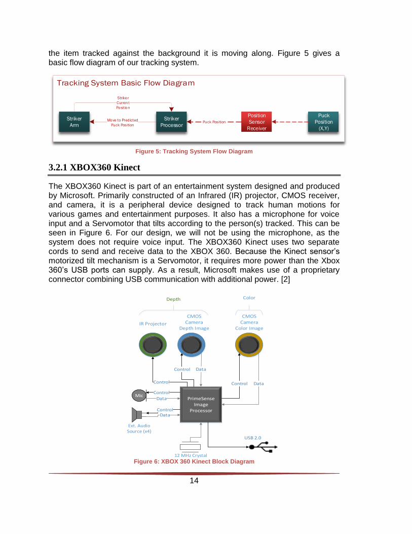
Tracking of the puck’s position is critical in our design in order for Striker to respond accurately. For this to happen we have a tracking device to record the puck’s position and send it to Striker’s processor to interpret and react accordingly. Based on most tracking algorithms, we primarily need a contrast in
14
the item tracked against the background it is moving along. Figure 5 gives a basic flow diagram of our tracking system.
Position
Sensor
Receiver
Puck
Position
(X,Y)
Striker
ProcessorPuck Position
Striker
ArmMove to Predicted
Puck Position
Striker
Current
Position
Figure 5: Tracking System Flow Diagram
3.2.1 XBOX360 Kinect
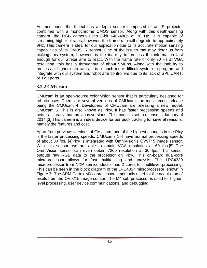
The XBOX360 Kinect is part of an entertainment system designed and produced by Microsoft. Primarily constructed of an Infrared (IR) projector, CMOS receiver, and camera, it is a peripheral device designed to track human motions for various games and entertainment purposes. It also has a microphone for voice input and a Servomotor that tilts according to the person(s) tracked. This can be seen in Figure 6. For our design, we will not be using the microphone, as the system does not require voice input. The XBOX360 Kinect uses two separate cords to send and receive data to the XBOX 360. Because the Kinect sensor’s motorized tilt mechanism is a Servomotor, it requires more power than the Xbox 360’s USB ports can supply. As a result, Microsoft makes use of a proprietary connector combining USB communication with additional power. [2]
PrimeSense Image
Processor
IR Projector
CMOSCamera
Depth Image
CMOSCamera
Color Image
Ext. Audio Source (x4)
Mic
12 MHz Crystal
Depth Color
Control
Control Data
Control Data
Control
Data
ControlData
USB 2.0
Figure 6: XBOX 360 Kinect Block Diagram
15
As mentioned, the Kinect has a depth sensor composed of an IR projector combined with a monochrome CMOS sensor. Along with this depth-sensing camera, the RGB camera uses 8-bit 640x480p at 30 Hz. It is capable of streaming higher bitrates; however, the frame rate will degrade to approximately 9Hz. This camera is ideal for our application due to its accurate motion sensing capabilities of its CMOS IR sensor. One of the issues that may deter us from picking this system, however, is the inability to process the information fast enough for our Striker arm to react. With the frame rate of only 30 Hz at VGA resolution, this has a throughput of about 9MBps. Along with the inability to process at higher data rates, it is a much more difficult system to program and integrate with our system and robot arm controllers due to its lack of SPI, UART, or TWI ports.
3.2.2 CMUcam
CMUcam is an open-source color vision sensor that is particularly designed for robotic uses. There are several versions of CMUcam, the most recent release being the CMUcam 4. Developers of CMUcam are releasing a new model, CMUcam 5. This is also known as Pixy. It has faster processing speeds and better accuracy than previous versions. This model is set to release in January of 2014.[3] This camera is an ideal device for our puck tracking for several reasons, namely the features and cost.
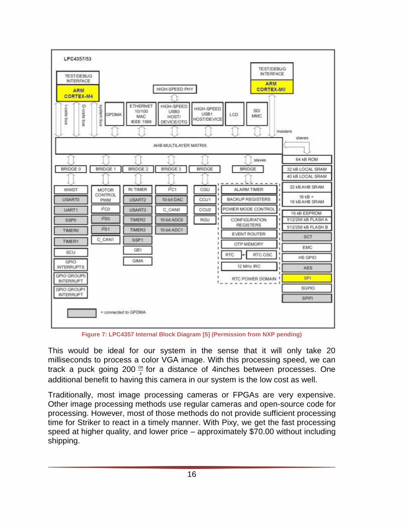
Apart from previous versions of CMUcam, one of the biggest changes in the Pixy is the faster processing speeds. CMUcams 1-4 have normal processing speeds of about 30 fps. [4]Pixy is integrated with OmniVision’s OV9715 image sensor. With this sensor, we are able to obtain VGA resolution at 60 fps.[5] The OmniVision sensor can even obtain 720p resolution at 30 fps. This sensor outputs raw RGB data to the processor on Pixy. This on-board dual-core microprocessor allows for fast multitasking and analysis. This LPC4330 microprocessor from NXP semiconductor has 2 cores for multilevel processing. This can be seen in the block diagram of the LPC4357 microprocessor, shown in Figure 7. The ARM Cortex M0 coprocessor is primarily used for the acquisition of pixels from the OV9715 image sensor. The M4 sub-processor is used for higher-level processing, user device communications, and debugging.
16
Figure 7: LPC4357 Internal Block Diagram [5] (Permission from NXP pending)
This would be ideal for our system in the sense that it will only take 20 milliseconds to process a color VGA image. With this processing speed, we can
track a puck going 200 for a distance of 4inches between processes. One
additional benefit to having this camera in our system is the low cost as well.
Traditionally, most image processing cameras or FPGAs are very expensive. Other image processing methods use regular cameras and open-source code for processing. However, most of those methods do not provide sufficient processing time for Striker to react in a timely manner. With Pixy, we get the fast processing speed at higher quality, and lower price – approximately $70.00 without including shipping.
17
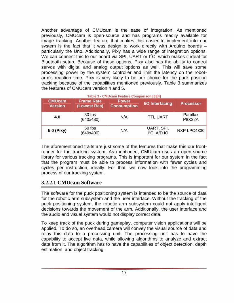
Another advantage of CMUcam is the ease of integration. As mentioned previously, CMUcam is open-source and has programs readily available for image tracking. Another feature that makes this easier to implement into our system is the fact that it was design to work directly with Arduino boards – particularly the Uno. Additionally, Pixy has a wide range of integration options. We can connect this to our board via SPI, UART or I2C, which makes it ideal for Bluetooth setup. Because of these options, Pixy also has the ability to control servos with digital and analog output options as well. This will save some processing power by the system controller and limit the latency on the robot-arm’s reaction time. Pixy is very likely to be our choice for the puck position tracking because of the capabilities mentioned previously. Table 3 summarizes the features of CMUcam version 4 and 5.
Table 3 - CMUcam Feature Comparison [3][4]
CMUcam Version
Frame Rate (Lowest Res)
Power Consumption
I/O Interfacing Processor
4.0 30 fps
(640x480) N/A TTL UART
Parallax P8X32A
5.0 (Pixy) 50 fps
(640x400) N/A
UART, SPI, I2C, A/D IO
NXP LPC4330
The aforementioned traits are just some of the features that make this our front-runner for the tracking system. As mentioned, CMUcam uses an open-source library for various tracking programs. This is important for our system in the fact that the program must be able to process information with fewer cycles and cycles per instruction, ideally. For that, we now look into the programming process of our tracking system.
3.2.2.1 CMUcam Software
The software for the puck positioning system is intended to be the source of data for the robotic arm subsystem and the user interface. Without the tracking of the puck positioning system, the robotic arm subsystem could not apply intelligent decisions towards the movement of the arm. Additionally, the user interface and the audio and visual system would not display correct data.
To keep track of the puck during gameplay, computer vision applications will be applied. To do so, an overhead camera will convey the visual source of data and relay this data to a processing unit. The processing unit has to have the capability to accept live data, while allowing algorithms to analyze and extract data from it. The algorithm has to have the capabilities of object detection, depth estimation, and object tracking.
18
Object detection is a vital aspect of the algorithms we create. The algorithm will need to correctly identify the puck from its background in a continuous manner through color detection. For our purposes, the general code will have to identify what pixel intensity corresponds with the hockey puck, form a matrix of data corresponding to the location of the edges, also known as edge detection, and also calculate the coordinates for the centroid of the object. For that reason, it will be important that the surface of the air hockey table not have any similar colors displayed as that of the hockey puck. This feature will allow for easier detection and analysis of the puck.
Depth estimation, for our purposes, refers to the process of converting pixel size to measurable distances. When the puck moves, the depth estimation algorithms will relay the exact position to the user interface. It is with the continuous calculation of the centroid’s coordinates and the depth estimation algorithms that the system will be able to track the puck. For our purposes, to track the puck means, extracting current coordinates, velocities and trajectories from the puck. With this data, the robotic arm will have the required data to make intelligent decisions.
To create these algorithms, there are many different languages to consider. These codes can be written from scratch using, C, C++, java or numerous other languages. The issue of writing a code from scratch is efficiency. There are numerous ways to write a code, but it is preferred that the code written uses the least amount of resources. Otherwise, the code may take extra cycles to extract data, a commodity that the robotic arm does not have. The algorithms we write for computer vision must be robust and fast. Therefore, it is best to use computer languages that have computer vision libraries and functions already optimized.
Many computer vision languages are used today. One of the possible languages we can use is OpenCV. OpenCV has a community of 47 thousand people. A large community gives the advantage of a larger source of knowledge to access when learning the language and obtaining example codes. OpenCV is based on the C++ language, which is a language that is very similar to C, a language we learned through our academics, and additionally a few of our members have had experience in programming with C++. [6]
As for the accessibility of OpenCV, many functions and libraries have already been optimized for our use. Some of these functions include, ‘videocapture()’ and ‘objectdetection’. Due to the popularity of OpenCV, open source programmable vision sensors have become available to purchase, such as the Pixy, which is mentioned before.
Pixy can be programmed using the graphical user interface that it comes with. The software and firmware that it comes with has built in functions that the user can take advantage of. The first function that is of major advantage to our project, is that with one push of a button, the user can specify what color Pixy needs to
19
track. By placing an object in front of Pixy and pressing the button, Pixy will automatically detect the color and begin object detection applications. Pixy also has the ability to distinguish objects by applying color combinations. By applying two colors side by side on an object, Pixy can be programmed to recognize complicated objects. [7]
Pixy’s software and firmware also give the benefit of allowing the user to see what Pixy sees from a computer screen. If an object of interest is detected, the software will name and outline the object on the screen. Pixy is capable of detecting seven different color signatures and hundreds of objects at a given time.
Since Pixy was designed to be open source, using their software is not the only means of programming this device. For previous versions of CMUcams, many users have developed optimized libraries for the Arduino that can be used towards programming CMUcams. In the Aruduino sketch, the interface that allows users to program Aurduinos, some of the function included in these libraries is the following: CMUcam4::begin(), CMUcam4::trackColor(), and CMUcam4::trackWindow(). These functions can be very beneficial in the programming process for computer vision applications. [8]
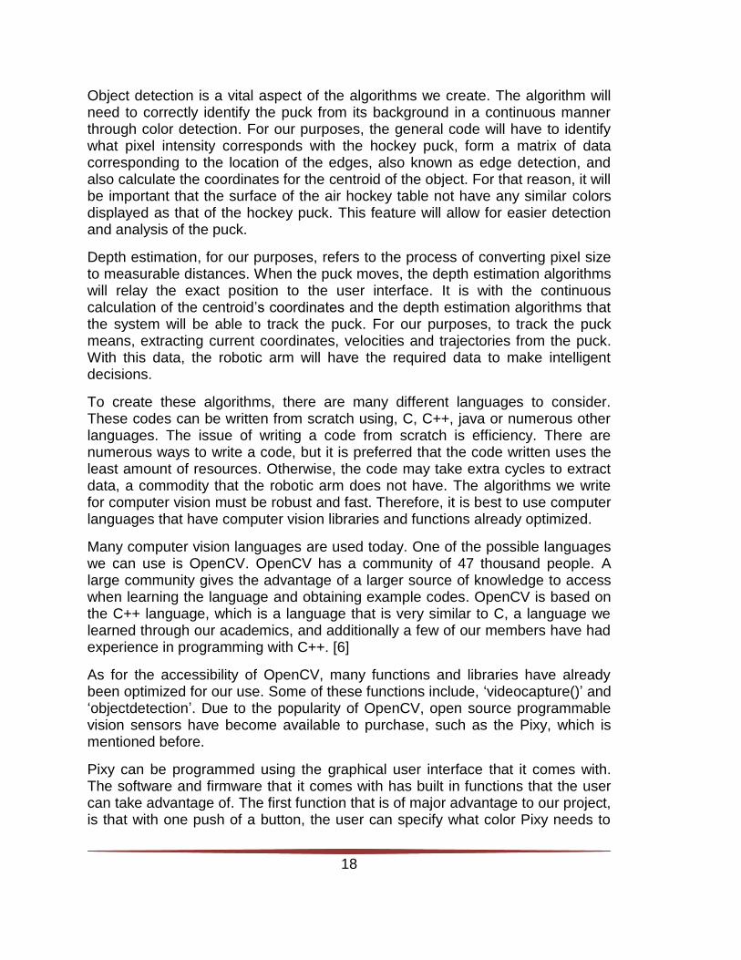
CMUcams have a simple way of color tracking. The idea behind color tracking for CMU cam is to set upper and lower limits for the pixel intensity values corresponding with the colors red, green, and blue. The CMU cam then has the ability to track colors within the specified range. With those limits, the CMUcam has the ability to search an image row wise, for the specified color range, and calculate edge detection and centroid positioning. The data that is extracted from these calculations result in digital or analog values that can be used by the robotic arm’s processors to drive the motors and servos in its system. The data relayed will be in the form of x-axis positioning and y-axis positioning of the robotic are and hockey pucks current position as well as the hockey pucks projected future position. This data will be sent wirelessly. The communication protocol will be further discussed in section 3.8. Figure 8 demonstrates how the coding for CMUcams work and how they can be programmed to send outputs through Bluetooth. [9]
20
StartInitialize CMU
Cam
Set Upper and Lower RGB Limits
Calculate (x,y) position for centroid
and trajectory
Bluetooth Modem Transmit
Delay
Is game being
played?
Yes DelayNo
Figure 8 – Tracking System Software Decision Process
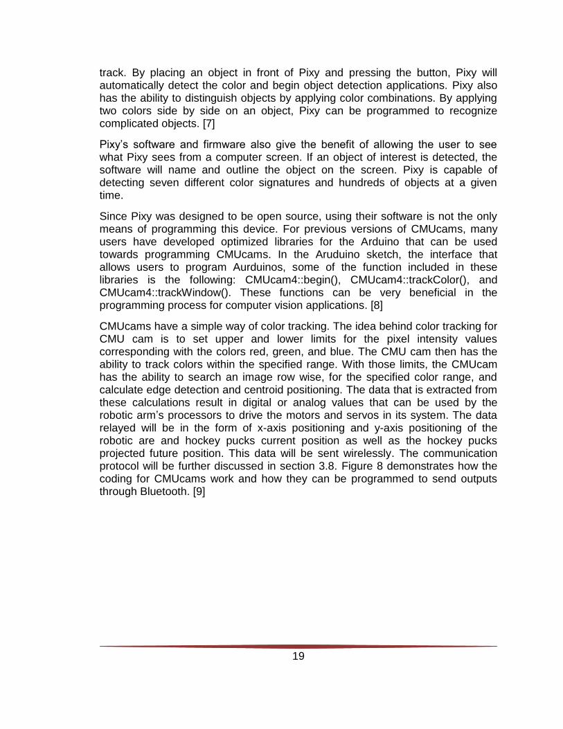
3.2.2.2 Pixy Hardware Interface
Pixy has an easy to use interface, which is shown in Figure 9. The button that allows the user to program color detection mentioned before is positioned at the top left of the figure. The USB connection allows the users to connect Pixy to a computer and use the software that it comes with to see what Pixy is viewing.
Figure 9 - Pixy's Hardware Interface [10] (Permission Obtained from Charmed Labs)
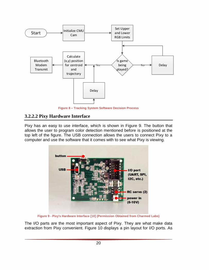
The I/O parts are the most important aspect of Pixy. They are what make data extraction from Pixy convenient. Figure 10 displays a pin layout for I/O ports. As
21
mentioned earlier, Pixy allows for several communication methods, which are described in section 3.8.
Figure 10 – Pixy’s pin layout for the I/O ports [10] (Permission Obtained from Charmed Labs)
3.2.3 Communication
The communication of our tracking system will be wireless. Most tracking devices have similar methods of communication all falling in the lines of UART transmission. For example, the XBOX 360 Kinect communicates via USB. This can pose to be advantageous in the fact that this is a fast method, however higher power consumption.
As mentioned in 3.2.2, Pixy uses many different types of communication protocols, which make it ideal for our project. For more details on how we can integrate this with our wireless system, refer to section 3.8 – Communication System.
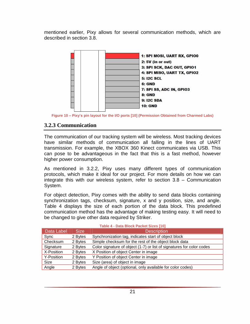
For object detection, Pixy comes with the ability to send data blocks containing synchronization tags, checksum, signature, x and y position, size, and angle. Table 4 displays the size of each portion of the data block. This predefined communication method has the advantage of making testing easy. It will need to be changed to give other data required by Striker.
Table 4 - Data Block Packet Sizes [10]
Data Label Size Description Sync 2 Bytes Synchronization tag, indicates start of object block
Checksum 2 Bytes Simple checksum for the rest of the object block data
Signature 2 Bytes Color signature of object (1-7) or list of signatures for color codes
X-Position 2 Bytes X Position of object Center in image
Y-Position 2 Bytes Y Position of object Center in image
Size 2 Bytes Size (area) of object in image
Angle 2 Bytes Angle of object (optional, only available for color codes)
22
3.3 Puck Return Mechanism
3.3.1 Design Overview
While looking at some air hockey games built from previous senior design projects, we realized that some of them implemented the sound system, the communication system, put cameras to record the game and others added sensors to track the position of the puck on the table. None of these projects had an automated puck return system. This observation pushed us to add an automated puck return mechanism. This will help players retrieve the air hockey puck after every goal scored in a shorter period. The automated puck return system will add more taste to the game; players will not only save more time but also experience a more interesting game. The puck return mechanism will be composed of a goal sensor used for tracking, a conveyer belt, a power switch, and a motor. This design will allow the air hockey puck to be returned automatically to the player.
Puck return will be achieved through the following mechanism; the puck will be identified into the goal by a sensor, which is controlled by a microcontroller. The microcontroller will make a decision whether to activate the power switch or not. If the player scores, the sensor will detect the air hockey puck and the power switch will activate the motor. Once the motor is on, it will activate the belt. As the belt moves, the puck will be returned to the player with ease every time at the same location. If no puck is being detected, the sensor will not take further action; however, the sensor will never stop searching for pucks. It will reset continuously to prepare for the next puck to come.
3.3.2 Goal Sensors
For our goal sensors, we had several ideas on how to implement our desired responses. Initially, we were considering photoelectric sensors used in the automation and manufacturing industry. We then considered a Passive Infrared sensor (PIR) that is used in many small electronic projects – often with Arduino. We also look into the approach of building a simple, cost-effective sensor with semiconductor photodetectors. We began our research with the photoelectric sensors.
Photoelectric Sensors
Photoelectric sensors are highly used in automation and theme park industries. These sensors provide a wide array of applications ranging from distance tracking to object detection. Typically, there are three methods of detection: diffused, retro-reflective and thru-beam. All three methods use a Light Emitting Diode (LED) as a light source. Retro-reflective sensors use visible light whereas thru-beam and diffused use Infrared (IR) LEDs. IR LEDs have a higher intensity
23
than these visible LEDs and operate between 10-3m and 10-6m wavelengths with a frequency range from 1012-1015 Hz.
Because we want to utilize a system that has limited power consumption, we consider options to reduce this for the photoelectric sensors. One way to do so is to modulate or pulse the LEDs at a constant frequency rather than letting it run continuously. This will not only increase the lifetime of the sensors, but will also reduce the average power consumed. This also gives protection against external light interference. This can prove to be advantageous to our project considering the various sources of light we will have, including the aesthetics.
Because the receiver is made up of a phototransistor, it only powers on when the emitter is powered during the high cycles. This provides very little time for mistaken light to give a false signal.
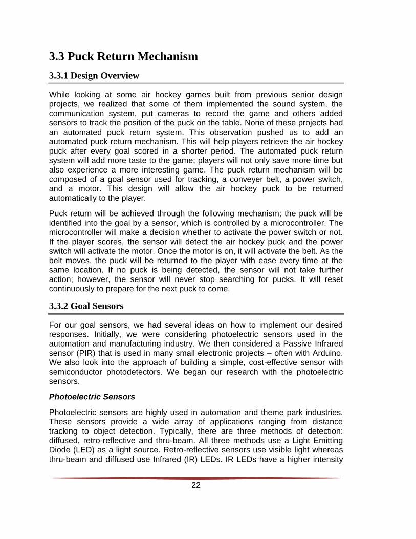
Generally, photoelectric sensors are made up of four main components as seen in Figure 10.
Light Source (LED)
Receiver (Phototransistor)
Signal Converter
Amplifier
Figure 10 - Internal Components of a Photoelectric Sensor [11] (Permission Obtained from Pepperl-
Fuchs)
From the phototransistor, the pulses received pass through a signal converter to generate an electrical signal and then compared for change in frequencies. You can condition these sensors to sense light or dark.
The amplifier mentioned above is used for LED intensity changing. In some instances and applications, it may be desirable to increase the intensity due to ambient conditions. For example, if the sensor is to be used in a ride at a theme park the sensitivity may need to be higher for a scene with high fog density versus clearer ambient conditions. For this, the amplifier will adjust the sensitivity by increasing the gain.
24
As mentioned earlier, photoelectric sensors have three primary methods of detection. For diffused mode (proximity mode), light is emitted onto an object and depending on various factors, the light is diffused at arbitrary angles. These factors affecting sensing range and diffusion angles are color, size and finish. From these arbitrary angles, some light is received into the receiver. For example, if the diffused sensor is trying to detect an object that is black and matte finish, sensitivity and/or position must be changed.
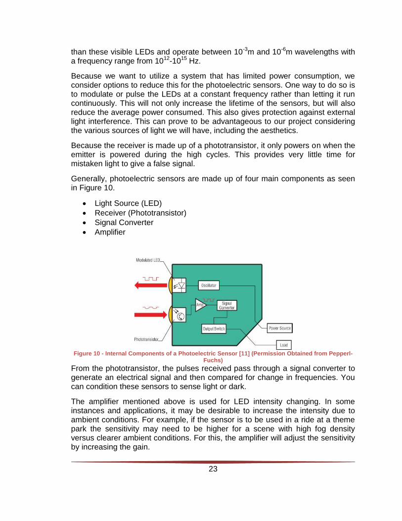
Retro-reflective mode uses a special reflector to establish a light path between the transmitter and receiver. This is the traditional method of object detection. One advantage of having the reflector in this application is the ease of alignment and longer sensing ranges. Although the sensing range is not essential, ease of installation is desired. The purpose of the reflector is to reflect the transmitter’s laser back into the receiver on a parallel axis Figure 11 and describe the nature of retro-reflective sensors. Notice the sensor has a series of filters that the electromagnetic waves pass through for clear deciphering. The clear lens protects the polarizing filter from scratches and outside debris, while the polarizing re-aligns the waves so that the receiver can determine the signal coming in is from the transmitter, and not an external light source.
Figure 11 - Retro-Reflective Sensor Instrumentation [11]
(Permission Obtained From Pepperl-Fuchs)
The other form of photoelectric sensors to operate is thru-beam mode. Thru-beam uses two sensors, one transmitter and the other a receiver. This method is known as the most efficient mode of the three. This mode allows for minor misalignments while still maintaining the ability to sense opaque targets. Another advantage to this is the ability to manipulate the trajectory of the light. This is also referred to as convergent sensing. This method is not an attractive option for our system due to the higher complexity and cost. Thus, we will not elaborate further on this system.
25
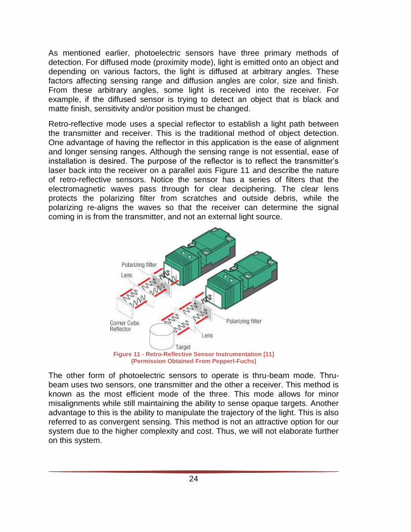
Typically, the connection and detection methods vary for photoelectric sensors. They can operate in a “light on” or “dark on” state. Essentially, these methods depend on phototransistor semiconductor composition. A NPN phototransistor configuration is a current sinking receiver. Conversely, a PNP is a current sourcing receiver. A current sinking configuration senses when light is being projected onto the receiver. When the light is interrupted, or an object has crossed its path then the signal is interrupted also to the controller to show this. Adversely the current sourcing is in an output state when light is not shining on the receiver. Figure 12 summarizes the conditions for both states, in regards to each photoelectric sensor. For our system design, it seems as though retro-reflective, ‘light on’ is ideal because we will be sensing when the puck has obstructed the light.
Figure 12 - Light On/ Dark On Condition Chart [12] (Permission Obtained from Pepperl-Fuchs)
Just as understanding the characteristic operation of photoelectric sensors is important; we must also understand how data is output to the microcontroller. For this, we look at the various forms of connections to the sensor. Typically, photoelectric sensors operate with a DC input voltage; however, some models can operate with AC signals as well. For our particular application, we will be looking into DC input. Figure 13 shows a Pepperl-Fuchs retro-reflective photoelectric sensor electrical configuration.
26
(a)
(b)
(c)
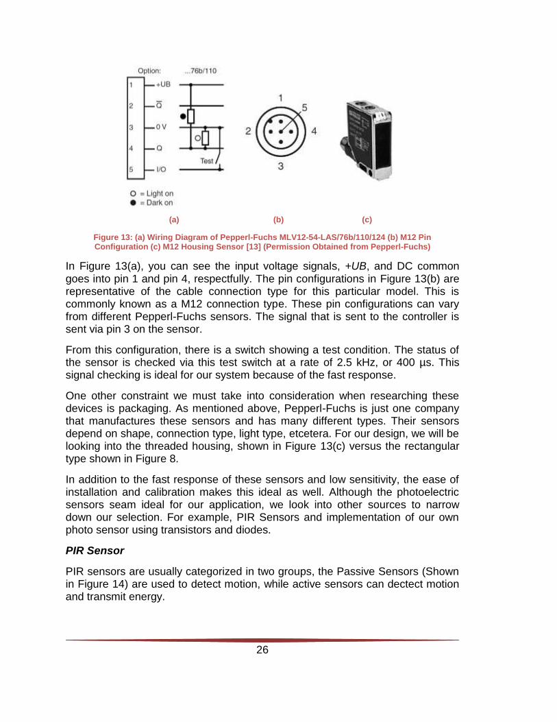
Figure 13: (a) Wiring Diagram of Pepperl-Fuchs MLV12-54-LAS/76b/110/124 (b) M12 Pin Configuration (c) M12 Housing Sensor [13] (Permission Obtained from Pepperl-Fuchs)
In Figure 13(a), you can see the input voltage signals, +UB, and DC common goes into pin 1 and pin 4, respectfully. The pin configurations in Figure 13(b) are representative of the cable connection type for this particular model. This is commonly known as a M12 connection type. These pin configurations can vary from different Pepperl-Fuchs sensors. The signal that is sent to the controller is sent via pin 3 on the sensor.
From this configuration, there is a switch showing a test condition. The status of the sensor is checked via this test switch at a rate of 2.5 kHz, or 400 µs. This signal checking is ideal for our system because of the fast response.
One other constraint we must take into consideration when researching these devices is packaging. As mentioned above, Pepperl-Fuchs is just one company that manufactures these sensors and has many different types. Their sensors depend on shape, connection type, light type, etcetera. For our design, we will be looking into the threaded housing, shown in Figure 13(c) versus the rectangular type shown in Figure 8.
In addition to the fast response of these sensors and low sensitivity, the ease of installation and calibration makes this ideal as well. Although the photoelectric sensors seam ideal for our application, we look into other sources to narrow down our selection. For example, PIR Sensors and implementation of our own photo sensor using transistors and diodes.
PIR Sensor
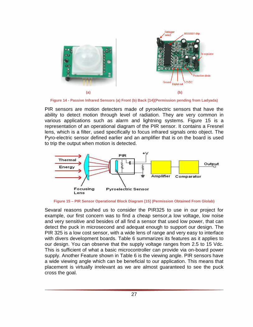
PIR sensors are usually categorized in two groups, the Passive Sensors (Shown in Figure 14) are used to detect motion, while active sensors can dectect motion and transmit energy.
27
(a)
(b)
Figure 14 - Passive Infrared Sensors (a) Front (b) Back [14](Permission pending from Ladyada)
PIR sensors are motion detecters made of pyroelectric sensors that have the ability to detect motion through level of radiation. They are very common in various applications such as alarm and lightning systems. Figure 15 is a representation of an operational diagram of the PIR sensor. It contains a Fresnel lens, which is a filter, used specifically to focus infrared signals onto object. The Pyro-electric sensor defined earlier and an amplifier that is on the board is used to trip the output when motion is detected.
Figure 15 – PIR Sensor Operational Block Diagram [15] (Permission Obtained From Glolab)
Sevaral reasons pushed us to consider the PIR325 to use in our project for example, our first concern was to find a cheap sensor,a low voltage, low noise and very sensitive and besides of all find a sensor that used low power, that can detect the puck in microsecond and adequat enough to support our design. The PIR 325 is a low cost sensor, with a wide lens of range and very easy to interface with divers development boards. Table 6 summarizes its features as it applies to our design. You can observe that the supply voltage ranges from 2.5 to 15 Vdc. This is sufficient of what a basic microcontroller can provide via on-board power supply. Another Feature shown in Table 6 is the viewing angle. PIR sensors have a wide viewing angle which can be beneficial to our application. This means that placement is virtually irrelevant as we are almost guaranteed to see the puck cross the goal.
28
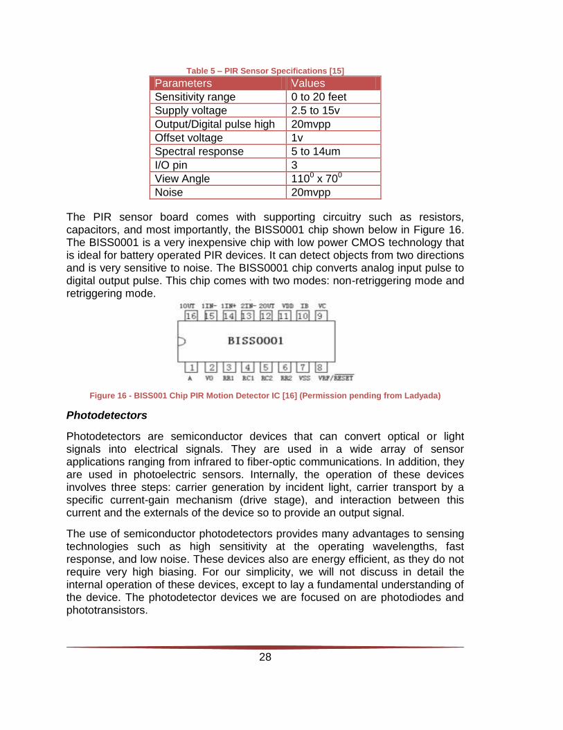
Table 5 – PIR Sensor Specifications [15]
Parameters Values
Sensitivity range 0 to 20 feet
Supply voltage 2.5 to 15v
Output/Digital pulse high 20mvpp
Offset voltage 1v
Spectral response 5 to 14um
I/O pin 3
View Angle 1100 x 700
Noise 20mvpp
The PIR sensor board comes with supporting circuitry such as resistors, capacitors, and most importantly, the BISS0001 chip shown below in Figure 16. The BISS0001 is a very inexpensive chip with low power CMOS technology that is ideal for battery operated PIR devices. It can detect objects from two directions and is very sensitive to noise. The BISS0001 chip converts analog input pulse to digital output pulse. This chip comes with two modes: non-retriggering mode and retriggering mode.
Figure 16 - BISS001 Chip PIR Motion Detector IC [16] (Permission pending from Ladyada)
Photodetectors
Photodetectors are semiconductor devices that can convert optical or light signals into electrical signals. They are used in a wide array of sensor applications ranging from infrared to fiber-optic communications. In addition, they are used in photoelectric sensors. Internally, the operation of these devices involves three steps: carrier generation by incident light, carrier transport by a specific current-gain mechanism (drive stage), and interaction between this current and the externals of the device so to provide an output signal.
The use of semiconductor photodetectors provides many advantages to sensing technologies such as high sensitivity at the operating wavelengths, fast response, and low noise. These devices also are energy efficient, as they do not require very high biasing. For our simplicity, we will not discuss in detail the internal operation of these devices, except to lay a fundamental understanding of the device. The photodetector devices we are focused on are photodiodes and phototransistors.
29
Photodiodes
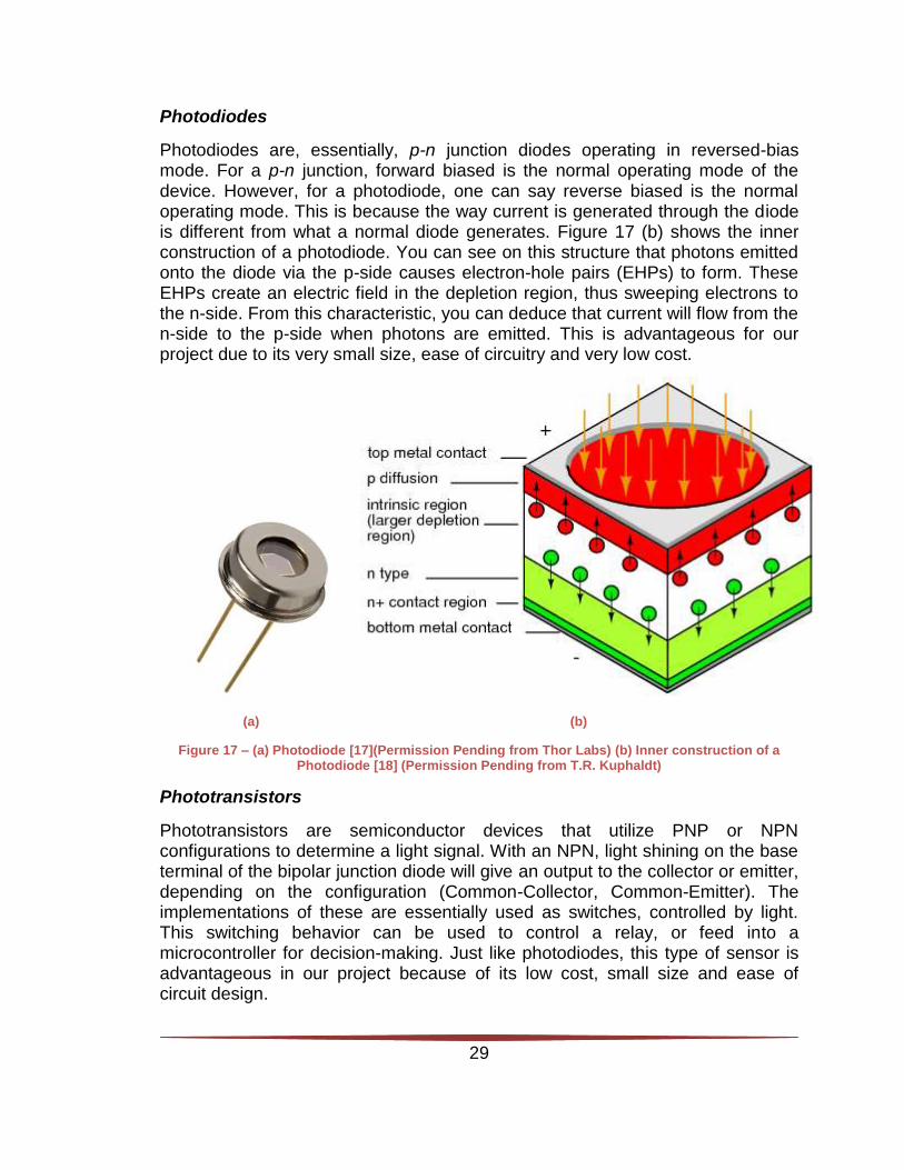
Photodiodes are, essentially, p-n junction diodes operating in reversed-bias mode. For a p-n junction, forward biased is the normal operating mode of the device. However, for a photodiode, one can say reverse biased is the normal operating mode. This is because the way current is generated through the diode is different from what a normal diode generates. Figure 17 (b) shows the inner construction of a photodiode. You can see on this structure that photons emitted onto the diode via the p-side causes electron-hole pairs (EHPs) to form. These EHPs create an electric field in the depletion region, thus sweeping electrons to the n-side. From this characteristic, you can deduce that current will flow from the n-side to the p-side when photons are emitted. This is advantageous for our project due to its very small size, ease of circuitry and very low cost.
(a)
(b)
Figure 17 – (a) Photodiode [17](Permission Pending from Thor Labs) (b) Inner construction of a Photodiode [18] (Permission Pending from T.R. Kuphaldt)
Phototransistors
Phototransistors are semiconductor devices that utilize PNP or NPN configurations to determine a light signal. With an NPN, light shining on the base terminal of the bipolar junction diode will give an output to the collector or emitter, depending on the configuration (Common-Collector, Common-Emitter). The implementations of these are essentially used as switches, controlled by light. This switching behavior can be used to control a relay, or feed into a microcontroller for decision-making. Just like photodiodes, this type of sensor is advantageous in our project because of its low cost, small size and ease of circuit design.
30
3.3.3 Motor for Conveyor Belt
One of the key elements that we need to make our automated puck return system possible is a motor. In this project, the role of the motor is to activate a conveyer belt so that the air hockey puck is returned to the player automatically. For the choice of a motor, we will be looking into speed, accuracy, angle of rotation and input voltage, size and price corresponding to our project. For example of motors, we have induction motors, stepper motors and Servomotors. We will mainly focus on steppers in this part.
Stepper Motor
A stepper motor is an electromagnetic motor that takes a digital input pulse to convert it to an analog output. A digital pulse on a stepper motor causes the motor to increment to a precise angle of rotation often called “step angle”. Stepper motors are open loop motors, which mean they do not provide feedback information. Steppers are affordable and can operate at low speed. Generally, a stepper motor comes with four.
A stepper motor can be unipolar or bipolar. In a unipolar stepper motor, each stator pole has two windings. Each winding creates one of the two magnetic poles. A bipolar stepper motor has only one winding per stator.
There are three types of stepper motors of interest. The first is a Permanent Magnet (PM) stepper motor, also called active rotor. The second is a Valuable Reluctance (VR) stepper motor, also called reactive rotor. The third is a Hybrid (HY), which is a combination of PM and VR.
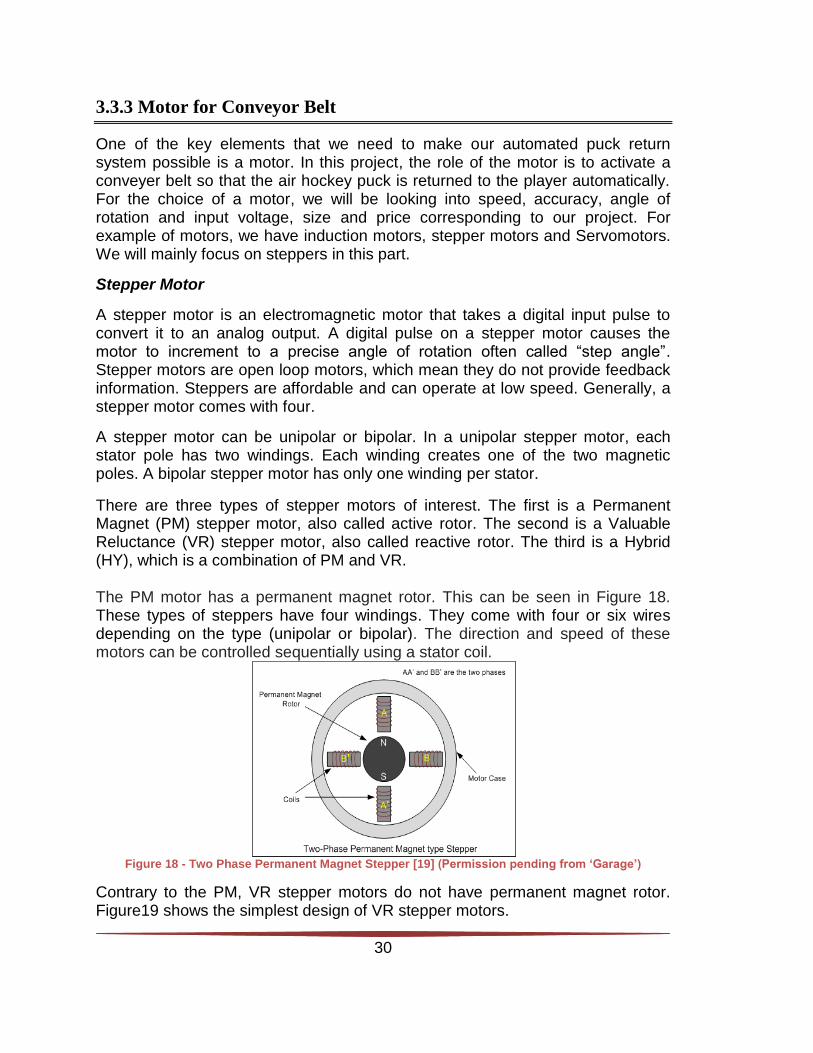
The PM motor has a permanent magnet rotor. This can be seen in Figure 18. These types of steppers have four windings. They come with four or six wires depending on the type (unipolar or bipolar). The direction and speed of these motors can be controlled sequentially using a stator coil.
Figure 18 - Two Phase Permanent Magnet Stepper [19] (Permission pending from ‘Garage’)
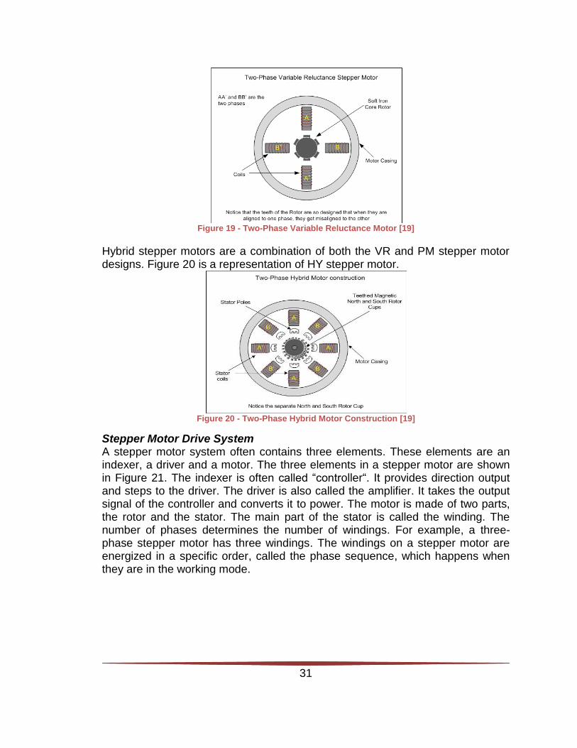
Contrary to the PM, VR stepper motors do not have permanent magnet rotor. Figure19 shows the simplest design of VR stepper motors.
31
Figure 19 - Two-Phase Variable Reluctance Motor [19]
Hybrid stepper motors are a combination of both the VR and PM stepper motor designs. Figure 20 is a representation of HY stepper motor.
Figure 20 - Two-Phase Hybrid Motor Construction [19]
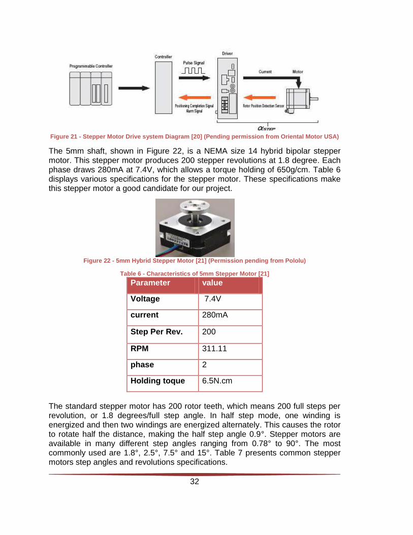
Stepper Motor Drive System A stepper motor system often contains three elements. These elements are an indexer, a driver and a motor. The three elements in a stepper motor are shown in Figure 21. The indexer is often called “controller“. It provides direction output and steps to the driver. The driver is also called the amplifier. It takes the output signal of the controller and converts it to power. The motor is made of two parts, the rotor and the stator. The main part of the stator is called the winding. The number of phases determines the number of windings. For example, a three-phase stepper motor has three windings. The windings on a stepper motor are energized in a specific order, called the phase sequence, which happens when they are in the working mode.
32
Figure 21 - Stepper Motor Drive system Diagram [20] (Pending permission from Oriental Motor USA)
The 5mm shaft, shown in Figure 22, is a NEMA size 14 hybrid bipolar stepper motor. This stepper motor produces 200 stepper revolutions at 1.8 degree. Each phase draws 280mA at 7.4V, which allows a torque holding of 650g/cm. Table 6 displays various specifications for the stepper motor. These specifications make this stepper motor a good candidate for our project.
Figure 22 - 5mm Hybrid Stepper Motor [21] (Permission pending from Pololu)
Table 6 - Characteristics of 5mm Stepper Motor [21]
Parameter value
Voltage 7.4V
current 280mA
Step Per Rev. 200
RPM 311.11
phase 2
Holding toque 6.5N.cm
The standard stepper motor has 200 rotor teeth, which means 200 full steps per revolution, or 1.8 degrees/full step angle. In half step mode, one winding is energized and then two windings are energized alternately. This causes the rotor to rotate half the distance, making the half step angle 0.9°. Stepper motors are available in many different step angles ranging from 0.78° to 90°. The most commonly used are 1.8°, 2.5°, 7.5° and 15°. Table 7 presents common stepper motors step angles and revolutions specifications.
33
Table 7 - Stepper Motor Comparison Chart
Step angle Step/revolution HY VR PM
0.45 800 yes no no
0.72 500 yes no no
0.9 400 yes no no
1.8 200 yes yes yes
1.875 192 yes no yes
2 180 yes no yes
2.5 144 yes no yes
3.6 100 yes no yes
5 72 yes yes yes
7.5 48 no yes yes
9 40 no no yes
15 24 no yes yes
18 20 no no yes
3.3.4 Interfacing with a Microcontroller
The PIR325 only has three pin connections. One pin is for ground, one is for signal and the last one is for power, which is usually from 3V to 5V. It can communicate easily with an MCU. As described earlier, the output of the PIR325 sensor is an active high when an object is detected or an active low when there is no detection. The role of the MCU is to control the on/off state of the puck return mechanism.
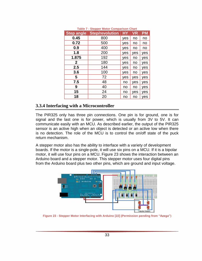
A stepper motor also has the ability to interface with a variety of development boards. If the motor is a single-pole, it will use six pins on a MCU. If it is a bipolar motor, it will use four pins on a MCU. Figure 23 shows the interaction between an Arduino board and a stepper motor. This stepper motor uses four digital pins from the Arduino board plus two other pins, which are ground and input voltage.
Figure 23 - Stepper Motor Interfacing with Arduino [22] (Permission pending from “Azega”)
34
3.4 Robot Arm
3.4.1 Design Overview
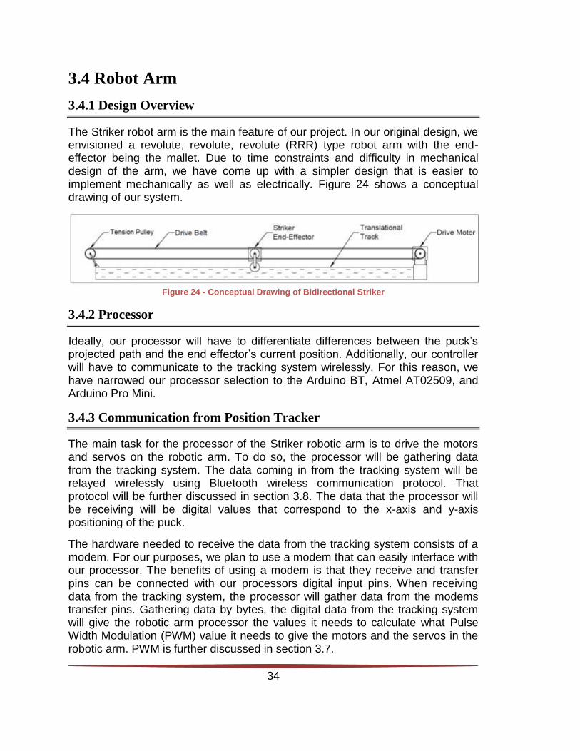
The Striker robot arm is the main feature of our project. In our original design, we envisioned a revolute, revolute, revolute (RRR) type robot arm with the end-effector being the mallet. Due to time constraints and difficulty in mechanical design of the arm, we have come up with a simpler design that is easier to implement mechanically as well as electrically. Figure 24 shows a conceptual drawing of our system.
Figure 24 - Conceptual Drawing of Bidirectional Striker
3.4.2 Processor
Ideally, our processor will have to differentiate differences between the puck’s projected path and the end effector’s current position. Additionally, our controller will have to communicate to the tracking system wirelessly. For this reason, we have narrowed our processor selection to the Arduino BT, Atmel AT02509, and Arduino Pro Mini.
3.4.3 Communication from Position Tracker
The main task for the processor of the Striker robotic arm is to drive the motors and servos on the robotic arm. To do so, the processor will be gathering data from the tracking system. The data coming in from the tracking system will be relayed wirelessly using Bluetooth wireless communication protocol. That protocol will be further discussed in section 3.8. The data that the processor will be receiving will be digital values that correspond to the x-axis and y-axis positioning of the puck.
The hardware needed to receive the data from the tracking system consists of a modem. For our purposes, we plan to use a modem that can easily interface with our processor. The benefits of using a modem is that they receive and transfer pins can be connected with our processors digital input pins. When receiving data from the tracking system, the processor will gather data from the modems transfer pins. Gathering data by bytes, the digital data from the tracking system will give the robotic arm processor the values it needs to calculate what Pulse Width Modulation (PWM) value it needs to give the motors and the servos in the robotic arm. PWM is further discussed in section 3.7.
35
3.4.4 Hardware
For our robot arm, we must have a mechanical system that is not only reliable, but also able to meet the electrical specifications of our system. For this, we must look into several factors to allow a successful design such as the motor selection, end effector, feedback, and translational track.
Drive System
For the translational movement along our track, we plan to use a motor to drive the robot arm. As previously mentioned, due to our lack of mechanical engineering knowledge, we are going with a simple, one-axis translation. We will have our motor drive a belt, which will further move the end-effector along a rail system. Our motor will have to rotate at a high rpm, be able to change direction quickly, and be able to stop at a predetermined position accurately. For these reasons, we look into stepper motors. Stepper motors have specific advantages for our system because of their accurate placement. Specific details on how the operation of stepper motor works is further explained in section 3.3.4. In this section, we discuss the advantage, as it applies to the robot arm.
Most stepper motors operate with a 1.8o per step rotation angle. This allows us to control where the motor will stop. These motors also have the ability to operate at very high rpm and high torque as well. Although these features make this ideal, there is one big downfall, which makes it difficult to work with – feedback.
Stepper motors usually do not contain a feedback loop to connect to a controller. This poses a problem because feedback will be essential to the design of the arm. A controller may send out a signal to the motor, however, there is no way for the controller to know if the motor moved, or its current location. It will assume that the movement was made. This, however, can be solved several different ways. We can include what is called a wheel encoder to provide a feedback loop to our controller.
Encoders are devices used in motor control circuits to provide a feedback to the motor controller. It does so by having two IR sensors to detect differences in black and white colors. They can be added to the end of a motor shaft or alongside a wheel to sense the rotational movement. Stickers of black and white patterns can be put to the sides of the spinning wheel to provide the contrasting colors for the sensors. You can see this in Figure 25.
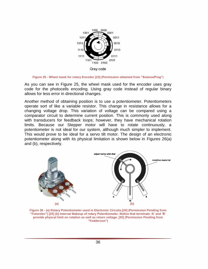
36
Figure 25 - Wheel mask for rotary Encoder [23] (Permission obtained from “ScienceProg”)
As you can see in Figure 25, the wheel mask used for the encoder uses gray code for the photocells encoding. Using gray code instead of regular binary allows for less error in directional changes.
Another method of obtaining position is to use a potentiometer. Potentiometers operate sort of like a variable resistor. This change in resistance allows for a changing voltage drop. This variation of voltage can be compared using a comparator circuit to determine current position. This is commonly used along with transducers for feedback loops; however, they have mechanical rotation limits. Because our Stepper motor will have to rotate continuously, a potentiometer is not ideal for our system, although much simpler to implement. This would prove to be ideal for a servo tilt motor. The design of an electronic potentiometer along with its physical limitation is shown below in Figures 26(a) and (b), respectively.
(a)
(b)
Figure 26 - (a) Rotary Potentiometer used in Electronic Circuits.[24] (Permission Pending from "Futurelec") [25] (b) Internal Makeup of rotary Potentiometer. Notice that terminals ‘A’ and ‘B’
provide physcal limit on rotation as well as return voltage. [25] (Permission Pending from "Fedderson")
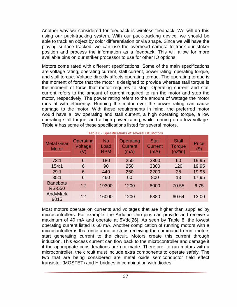
37
Another way we considered for feedback is wireless feedback. We will do this using our puck-tracking system. With our puck-tracking device, we should be able to track an object by color differentiation or via shape. Since we will have the playing surface tracked, we can use the overhead camera to track our striker position and process the information as a feedback. This will allow for more available pins on our striker processor to use for other IO options.
Motors come rated with different specifications. Some of the main specifications are voltage rating, operating current, stall current, power rating, operating torque, and stall torque. Voltage directly affects operating torque. The operating torque is the moment of force that the motor is designed to provide whereas stall torque is the moment of force that motor requires to stop. Operating current and stall current refers to the amount of current required to run the motor and stop the motor, respectively. The power rating refers to the amount of wattage the motor runs at with efficiency. Running the motor over the power rating can cause damage to the motor. With these requirements in mind, the preferred motor would have a low operating and stall current, a high operating torque, a low operating stall torque, and a high power rating, while running on a low voltage. Table # has some of these specifications listed for several motors.
Table 8 - Specifications of several DC Motors
Metal Gear Motor
Operating Voltage
(V)
No Load RPM
Operating Current
(mA)
Stall Current
(mA)
Stall Torque (oz*in)
Price ($)
73:1 6 180 250 3300 60 19.95
154:1 6 90 250 3300 120 19.95
29:1 6 440 250 2200 25 19.95
35:1 6 460 60 800 13 17.95
Banebots RS-550
12 19300 1200 8000 70.55 6.75
AndyMark 9015
12 16000 1200 6380 60.64 13.00
Most motors operate on currents and voltages that are higher than supplied by microcontrollers. For example, the Arduino Uno pins can provide and receive a maximum of 40 mA and operate at 5Vdc[26]. As seen by Table 8, the lowest operating current listed is 60 mA. Another complication of running motors with a microcontroller is that once a motor stops receiving the command to run, motors start generating current to the circuit. Motors create this current through induction. This excess current can flow back to the microcontroller and damage it if the appropriate considerations are not made. Therefore, to run motors with a microcontroller, the circuit must include extra components to operate safely. The two that are being considered are metal oxide semiconductor field effect transistor (MOSFET) and H-bridges in combination with diodes.
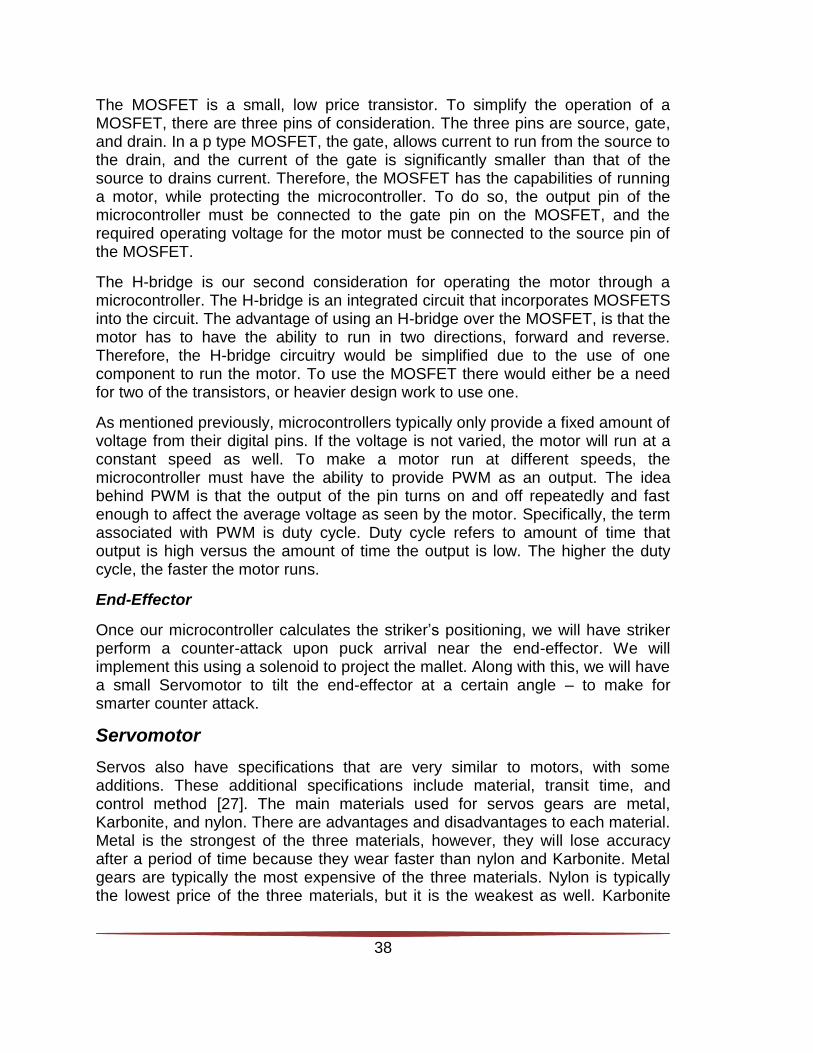
38
The MOSFET is a small, low price transistor. To simplify the operation of a MOSFET, there are three pins of consideration. The three pins are source, gate, and drain. In a p type MOSFET, the gate, allows current to run from the source to the drain, and the current of the gate is significantly smaller than that of the source to drains current. Therefore, the MOSFET has the capabilities of running a motor, while protecting the microcontroller. To do so, the output pin of the microcontroller must be connected to the gate pin on the MOSFET, and the required operating voltage for the motor must be connected to the source pin of the MOSFET.
The H-bridge is our second consideration for operating the motor through a microcontroller. The H-bridge is an integrated circuit that incorporates MOSFETS into the circuit. The advantage of using an H-bridge over the MOSFET, is that the motor has to have the ability to run in two directions, forward and reverse. Therefore, the H-bridge circuitry would be simplified due to the use of one component to run the motor. To use the MOSFET there would either be a need for two of the transistors, or heavier design work to use one.
As mentioned previously, microcontrollers typically only provide a fixed amount of voltage from their digital pins. If the voltage is not varied, the motor will run at a constant speed as well. To make a motor run at different speeds, the microcontroller must have the ability to provide PWM as an output. The idea behind PWM is that the output of the pin turns on and off repeatedly and fast enough to affect the average voltage as seen by the motor. Specifically, the term associated with PWM is duty cycle. Duty cycle refers to amount of time that output is high versus the amount of time the output is low. The higher the duty cycle, the faster the motor runs.
End-Effector
Once our microcontroller calculates the striker’s positioning, we will have striker perform a counter-attack upon puck arrival near the end-effector. We will implement this using a solenoid to project the mallet. Along with this, we will have a small Servomotor to tilt the end-effector at a certain angle – to make for smarter counter attack.
Servomotor
Servos also have specifications that are very similar to motors, with some additions. These additional specifications include material, transit time, and control method [27]. The main materials used for servos gears are metal, Karbonite, and nylon. There are advantages and disadvantages to each material. Metal is the strongest of the three materials, however, they will lose accuracy after a period of time because they wear faster than nylon and Karbonite. Metal gears are typically the most expensive of the three materials. Nylon is typically the lowest price of the three materials, but it is the weakest as well. Karbonite
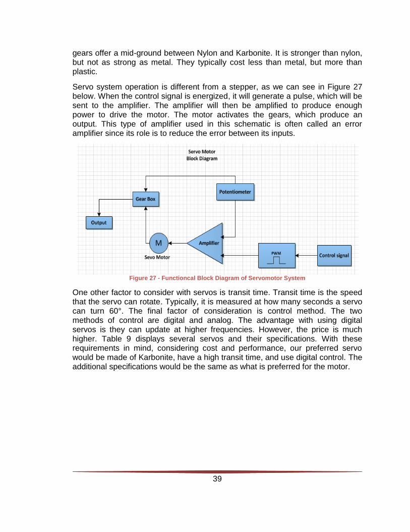
39
gears offer a mid-ground between Nylon and Karbonite. It is stronger than nylon, but not as strong as metal. They typically cost less than metal, but more than plastic.
Servo system operation is different from a stepper, as we can see in Figure 27 below. When the control signal is energized, it will generate a pulse, which will be sent to the amplifier. The amplifier will then be amplified to produce enough power to drive the motor. The motor activates the gears, which produce an output. This type of amplifier used in this schematic is often called an error amplifier since its role is to reduce the error between its inputs.
Figure 27 - Functioncal Block Diagram of Servomotor System
One other factor to consider with servos is transit time. Transit time is the speed that the servo can rotate. Typically, it is measured at how many seconds a servo can turn 60°. The final factor of consideration is control method. The two methods of control are digital and analog. The advantage with using digital servos is they can update at higher frequencies. However, the price is much higher. Table 9 displays several servos and their specifications. With these requirements in mind, considering cost and performance, our preferred servo would be made of Karbonite, have a high transit time, and use digital control. The additional specifications would be the same as what is preferred for the motor.
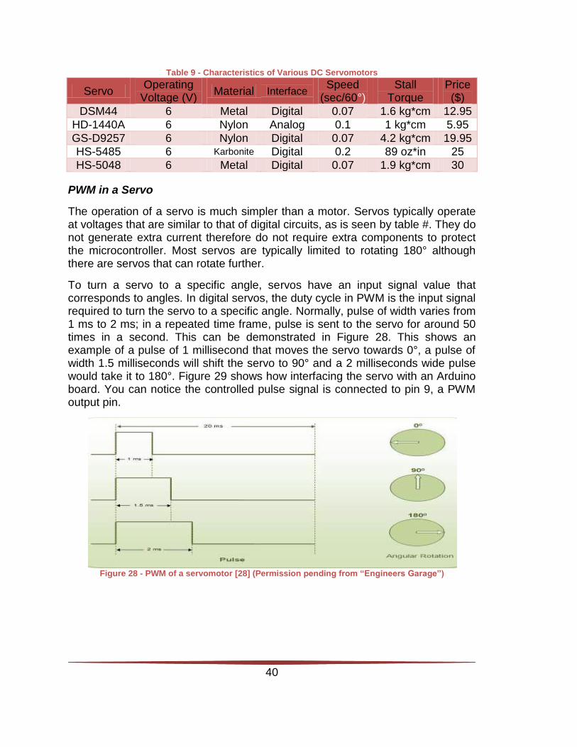
40
Table 9 - Characteristics of Various DC Servomotors
Servo Operating
Voltage (V) Material Interface
Speed (sec/60°)
Stall Torque
Price ($)
DSM44 6 Metal Digital 0.07 1.6 kg*cm 12.95
HD-1440A 6 Nylon Analog 0.1 1 kg*cm 5.95
GS-D9257 6 Nylon Digital 0.07 4.2 kg*cm 19.95
HS-5485 6 Karbonite Digital 0.2 89 oz*in 25
HS-5048 6 Metal Digital 0.07 1.9 kg*cm 30
PWM in a Servo
The operation of a servo is much simpler than a motor. Servos typically operate at voltages that are similar to that of digital circuits, as is seen by table #. They do not generate extra current therefore do not require extra components to protect the microcontroller. Most servos are typically limited to rotating 180° although there are servos that can rotate further.
To turn a servo to a specific angle, servos have an input signal value that corresponds to angles. In digital servos, the duty cycle in PWM is the input signal required to turn the servo to a specific angle. Normally, pulse of width varies from 1 ms to 2 ms; in a repeated time frame, pulse is sent to the servo for around 50 times in a second. This can be demonstrated in Figure 28. This shows an example of a pulse of 1 millisecond that moves the servo towards 0°, a pulse of width 1.5 milliseconds will shift the servo to 90° and a 2 milliseconds wide pulse would take it to 180°. Figure 29 shows how interfacing the servo with an Arduino board. You can notice the controlled pulse signal is connected to pin 9, a PWM output pin.
Figure 28 - PWM of a servomotor [28] (Permission pending from “Engineers Garage”)
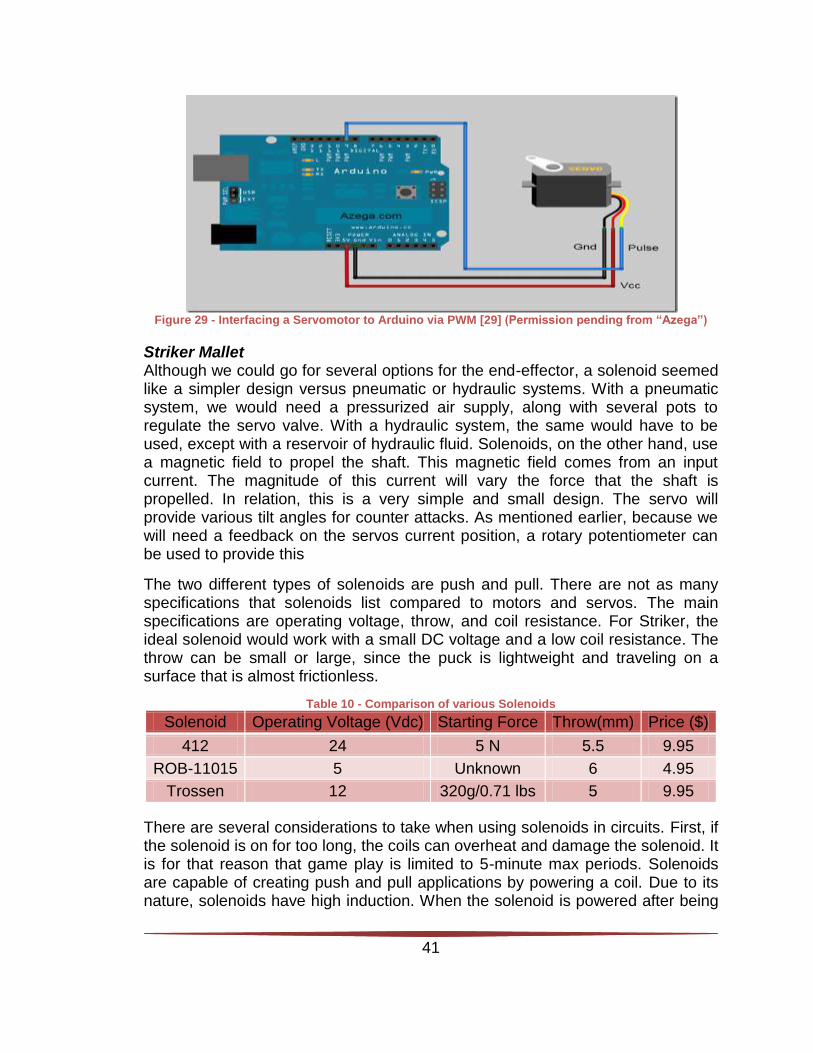
41
Figure 29 - Interfacing a Servomotor to Arduino via PWM [29] (Permission pending from “Azega”)
Striker Mallet Although we could go for several options for the end-effector, a solenoid seemed like a simpler design versus pneumatic or hydraulic systems. With a pneumatic system, we would need a pressurized air supply, along with several pots to regulate the servo valve. With a hydraulic system, the same would have to be used, except with a reservoir of hydraulic fluid. Solenoids, on the other hand, use a magnetic field to propel the shaft. This magnetic field comes from an input current. The magnitude of this current will vary the force that the shaft is propelled. In relation, this is a very simple and small design. The servo will provide various tilt angles for counter attacks. As mentioned earlier, because we will need a feedback on the servos current position, a rotary potentiometer can be used to provide this
The two different types of solenoids are push and pull. There are not as many specifications that solenoids list compared to motors and servos. The main specifications are operating voltage, throw, and coil resistance. For Striker, the ideal solenoid would work with a small DC voltage and a low coil resistance. The throw can be small or large, since the puck is lightweight and traveling on a surface that is almost frictionless.
Table 10 - Comparison of various Solenoids
Solenoid Operating Voltage (Vdc) Starting Force Throw(mm) Price ($)
412 24 5 N 5.5 9.95
ROB-11015 5 Unknown 6 4.95
Trossen 12 320g/0.71 lbs 5 9.95
There are several considerations to take when using solenoids in circuits. First, if the solenoid is on for too long, the coils can overheat and damage the solenoid. It is for that reason that game play is limited to 5-minute max periods. Solenoids are capable of creating push and pull applications by powering a coil. Due to its nature, solenoids have high induction. When the solenoid is powered after being
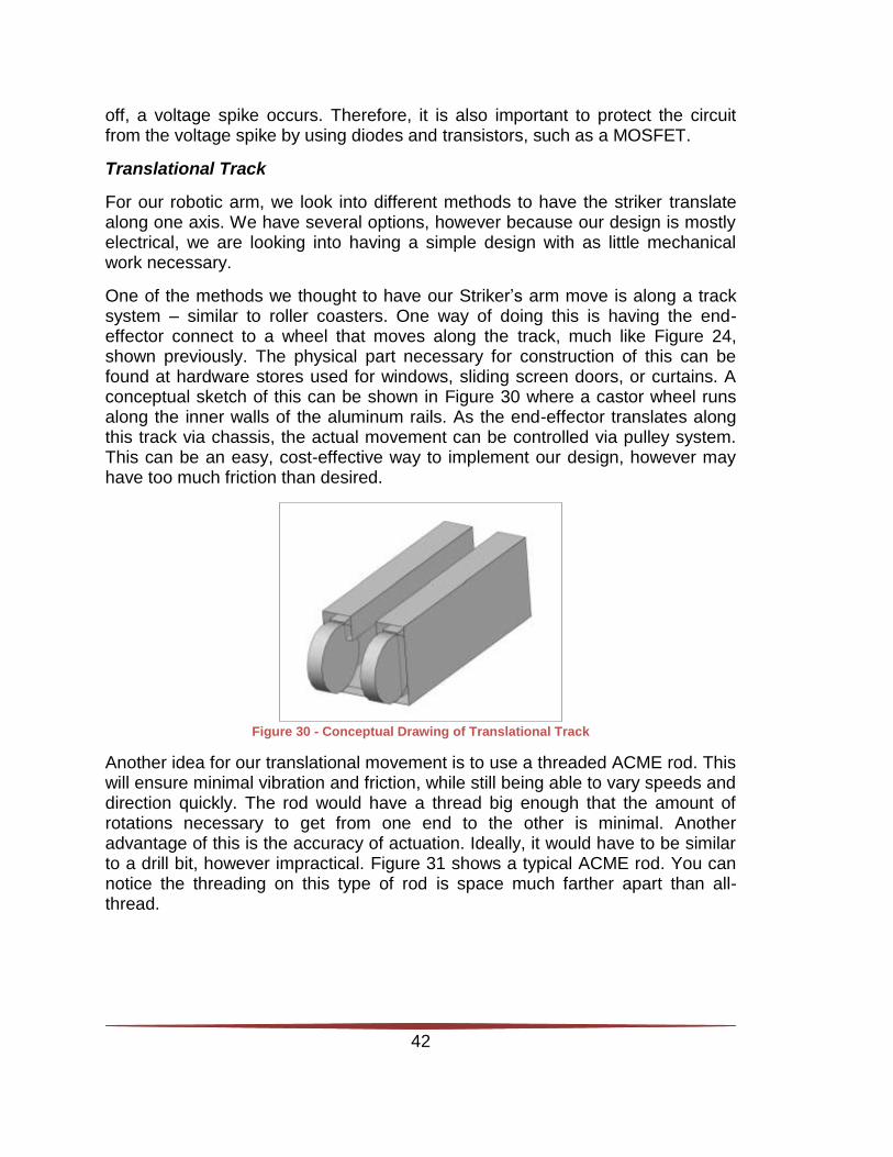
42
off, a voltage spike occurs. Therefore, it is also important to protect the circuit from the voltage spike by using diodes and transistors, such as a MOSFET.
Translational Track
For our robotic arm, we look into different methods to have the striker translate along one axis. We have several options, however because our design is mostly electrical, we are looking into having a simple design with as little mechanical work necessary.
One of the methods we thought to have our Striker’s arm move is along a track system – similar to roller coasters. One way of doing this is having the end-effector connect to a wheel that moves along the track, much like Figure 24, shown previously. The physical part necessary for construction of this can be found at hardware stores used for windows, sliding screen doors, or curtains. A conceptual sketch of this can be shown in Figure 30 where a castor wheel runs along the inner walls of the aluminum rails. As the end-effector translates along this track via chassis, the actual movement can be controlled via pulley system. This can be an easy, cost-effective way to implement our design, however may have too much friction than desired.
Figure 30 - Conceptual Drawing of Translational Track
Another idea for our translational movement is to use a threaded ACME rod. This will ensure minimal vibration and friction, while still being able to vary speeds and direction quickly. The rod would have a thread big enough that the amount of rotations necessary to get from one end to the other is minimal. Another advantage of this is the accuracy of actuation. Ideally, it would have to be similar to a drill bit, however impractical. Figure 31 shows a typical ACME rod. You can notice the threading on this type of rod is space much farther apart than all-thread.
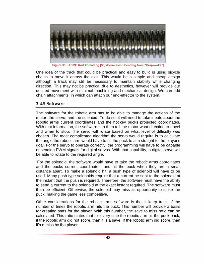
43
Figure 31 - ACME Rod Threading [30] (Permission Pending from “Crapworks”)
One idea of the track that could be practical and easy to build is using bicycle chains to move it across the axis. This would be a simple and cheap design although a track may still be necessary to maintain stability while changing direction. This may not be practical due to aesthetics, however will provide our desired movement with minimal machining and mechanical design. We can add chain attachments, in which can attach our end-effector to the system.
3.4.5 Software
The software for the robotic arm has to be able to manage the actions of the motor, the servo, and the solenoid. To do so, it will need to take inputs about the robotic arms current coordinates and the hockey pucks projected coordinates. With that information, the software can then tell the motor what direction to travel and when to stop. The servo will rotate based on what level of difficulty was chosen. The most complicated algorithm the servo would require is to calculate the angle the robotic arm would have to hit the puck to aim straight to the player’s goal. For the servo to operate correctly, the programming will have to be capable of sending PWM signals for digital servos. With that capability, a digital servo will be able to rotate to the required angle.
For the solenoid, the software would have to take the robotic arms coordinates and the pucks current coordinates, and hit the puck when they are a small distance apart. To make a solenoid hit, a push type of solenoid will have to be used. Many push type solenoids require that a current be sent to the solenoid at the instant that the push is required. Therefore, the software must have the ability to send a current to the solenoid at the exact instant required. The software must then be efficient. Otherwise, the solenoid may miss its opportunity to strike the puck, making the game less competitive.
Other considerations for the robotic arms software is that it keep track of the number of times the robotic arm hits the puck. This number will provide a basis for creating stats for the player. With this number, the save to miss ratio can be calculated. This ratio states that for every time the robotic arm hit the puck back, if the robotic arm did not score, than it is a save. If the robotic arm did score, than it’s a miss by the player.
44
3.5 Air Hockey Table
Acquisition of an air hockey table is necessary for testing and demonstration purposes. A multitude of table options is available to meet our constraints. It was desirable that the puck travel be made possible by means of a cushion of air in lieu of a smooth surface that is plastic in construction.
3.5.1 Harvard Action Arena 7’ Air Hockey Table
The Harvard 7 ft. Action Air Hockey table is one foot shorter than regulation tournament play length of 8 ft. but larger than most air hockey tables that are present in most homes. For example, the other table option had a length of only 60”. This would have serious ramifications to the robots hit rate with the puck. The assembled table dimensions for the Harvard Table 84”L x 44”W x 33”H. The playing surface is a pvc laminate that has air supplied from a 110 V motor. Overall, this table meets are our requirements.[31]
3.6 Audio System
The process of having audio effects can be accomplished using a separate controller for audio processing or combine it with a microcontroller that has the ability to do both. However, it may simplify the process by having the audio controlled from a separate controller instead of integrating sounds effects with video processing.
3.6.1 Speakers
Two styles of speaker choices are considered for the display area that will be positioned above the playing surface. One choice is to use two inexpensive computer speakers that will be positioned on either side of the display. A more convenient choice is to use a speaker bar that can be affixed to the top of the display. In both cases, a simple connection to the monitor is available.
3.6.2 Audio Controller
A promising microcontroller to implement sound effect is the C5000 Audio Touch Booster Pack from Texas Instruments. This device is an ultra-low digital signal processing (DSP) driven application. DSP by definition is the process of taking analog signals and converting those signals to digital signals by means of transforming to discrete time. This transformation is accomplished by Fast Fourier Transform algorithm. Clarity of the signal can be improved by padding zeros to the algorithm. Generally, the more zeros the better. Moreover, the DSP process is accomplished using a preprogrammed micro-SD card (Figure 32) that’s included with the function code. The C5000 is capable of record and
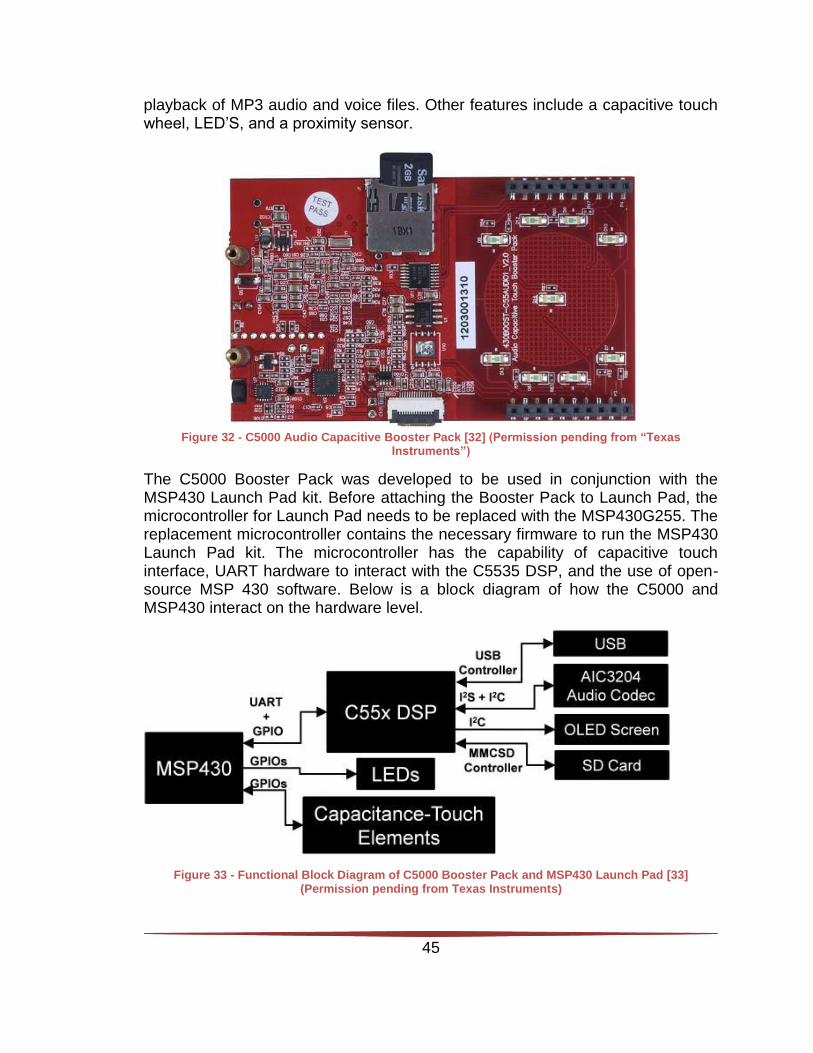
45
playback of MP3 audio and voice files. Other features include a capacitive touch wheel, LED’S, and a proximity sensor.
Figure 32 - C5000 Audio Capacitive Booster Pack [32] (Permission pending from “Texas
Instruments”)
The C5000 Booster Pack was developed to be used in conjunction with the MSP430 Launch Pad kit. Before attaching the Booster Pack to Launch Pad, the microcontroller for Launch Pad needs to be replaced with the MSP430G255. The replacement microcontroller contains the necessary firmware to run the MSP430 Launch Pad kit. The microcontroller has the capability of capacitive touch interface, UART hardware to interact with the C5535 DSP, and the use of open-source MSP 430 software. Below is a block diagram of how the C5000 and MSP430 interact on the hardware level.
Figure 33 - Functional Block Diagram of C5000 Booster Pack and MSP430 Launch Pad [33] (Permission pending from Texas Instruments)
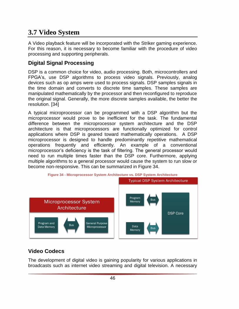
46
3.7 Video System
A Video playback feature will be incorporated with the Striker gaming experience. For this reason, it is necessary to become familiar with the procedure of video processing and supporting peripherals.
Digital Signal Processing
DSP is a common choice for video, audio processing. Both, microcontrollers and FPGA’s, use DSP algorithms to process video signals. Previously, analog devices such as op amps were used to process signals. DSP samples signals in the time domain and converts to discrete time samples. These samples are manipulated mathematically by the processor and then reconfigured to reproduce the original signal. Generally, the more discrete samples available, the better the resolution. [34]
A typical microprocessor can be programmed with a DSP algorithm but the microprocessor would prove to be inefficient for the task. The fundamental difference between the microprocessor system architecture and the DSP architecture is that microprocessors are functionally optimized for control applications where DSP is geared toward mathematically operations. A DSP microprocessor is designed to handle predominantly repetitive mathematical operations frequently and efficiently. An example of a conventional microprocessor’s deficiency is the task of filtering. The general processor would need to run multiple times faster than the DSP core. Furthermore, applying multiple algorithms to a general processor would cause the system to run slow or become non-responsive. This can be summarized in Figure 34.
Figure 34 - Microprocessor System Architecture vs. DSP System Architecture
Program and
Data MemoryBus
General Purpose
Microprocessor
Program
Memory
Data
MemoryBus
DSP Core
Bus
Video Codecs
The development of digital video is gaining popularity for various applications in broadcasts such as internet video streaming and digital television. A necessary
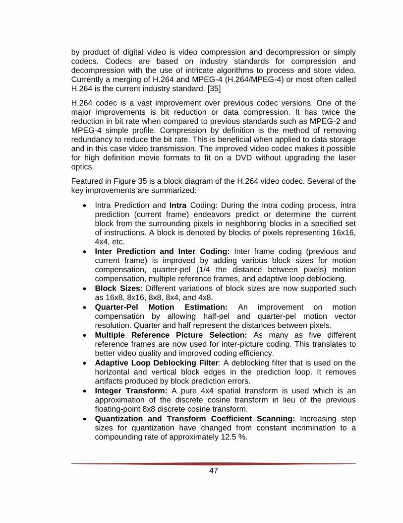
47
by product of digital video is video compression and decompression or simply codecs. Codecs are based on industry standards for compression and decompression with the use of intricate algorithms to process and store video. Currently a merging of H.264 and MPEG-4 (H.264/MPEG-4) or most often called H.264 is the current industry standard. [35]
H.264 codec is a vast improvement over previous codec versions. One of the major improvements is bit reduction or data compression. It has twice the reduction in bit rate when compared to previous standards such as MPEG-2 and MPEG-4 simple profile. Compression by definition is the method of removing redundancy to reduce the bit rate. This is beneficial when applied to data storage and in this case video transmission. The improved video codec makes it possible for high definition movie formats to fit on a DVD without upgrading the laser optics.
Featured in Figure 35 is a block diagram of the H.264 video codec. Several of the key improvements are summarized:
Intra Prediction and Intra Coding: During the intra coding process, intra prediction (current frame) endeavors predict or determine the current block from the surrounding pixels in neighboring blocks in a specified set of instructions. A block is denoted by blocks of pixels representing 16x16, 4x4, etc.
Inter Prediction and Inter Coding: Inter frame coding (previous and current frame) is improved by adding various block sizes for motion compensation, quarter-pel (1/4 the distance between pixels) motion compensation, multiple reference frames, and adaptive loop deblocking.
Block Sizes: Different variations of block sizes are now supported such as 16x8, 8x16, 8x8, 8x4, and 4x8.
Quarter-Pel Motion Estimation: An improvement on motion compensation by allowing half-pel and quarter-pel motion vector resolution. Quarter and half represent the distances between pixels.
Multiple Reference Picture Selection: As many as five different reference frames are now used for inter-picture coding. This translates to better video quality and improved coding efficiency.
Adaptive Loop Deblocking Filter: A deblocking filter that is used on the horizontal and vertical block edges in the prediction loop. It removes artifacts produced by block prediction errors.
Integer Transform: A pure 4x4 spatial transform is used which is an approximation of the discrete cosine transform in lieu of the previous floating-point 8x8 discrete cosine transform.
Quantization and Transform Coefficient Scanning: Increasing step sizes for quantization have changed from constant incrimination to a compounding rate of approximately 12.5 %.
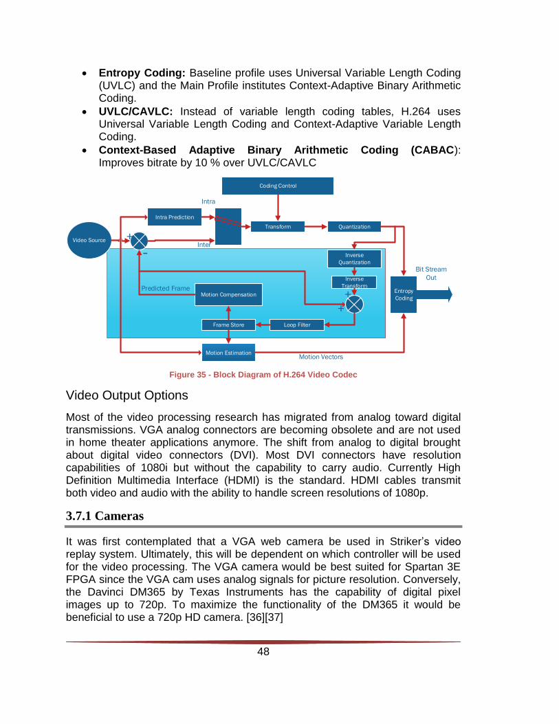
48
Entropy Coding: Baseline profile uses Universal Variable Length Coding (UVLC) and the Main Profile institutes Context-Adaptive Binary Arithmetic Coding.
UVLC/CAVLC: Instead of variable length coding tables, H.264 uses Universal Variable Length Coding and Context-Adaptive Variable Length Coding.
Context-Based Adaptive Binary Arithmetic Coding (CABAC): Improves bitrate by 10 % over UVLC/CAVLC
Intra Prediction
Coding Control
Transform Quantization
Inverse
Quantization
Inverse
TransformEntropy
CodingMotion Compensation
Frame Store
Motion Estimation
Loop Filter
Video Source +
Intra
Inter
Motion Vectors
+
-
+
+Predicted Frame
Bit Stream
Out
Figure 35 - Block Diagram of H.264 Video Codec
Video Output Options
Most of the video processing research has migrated from analog toward digital transmissions. VGA analog connectors are becoming obsolete and are not used in home theater applications anymore. The shift from analog to digital brought about digital video connectors (DVI). Most DVI connectors have resolution capabilities of 1080i but without the capability to carry audio. Currently High Definition Multimedia Interface (HDMI) is the standard. HDMI cables transmit both video and audio with the ability to handle screen resolutions of 1080p.
3.7.1 Cameras
It was first contemplated that a VGA web camera be used in Striker’s video replay system. Ultimately, this will be dependent on which controller will be used for the video processing. The VGA camera would be best suited for Spartan 3E FPGA since the VGA cam uses analog signals for picture resolution. Conversely, the Davinci DM365 by Texas Instruments has the capability of digital pixel images up to 720p. To maximize the functionality of the DM365 it would be beneficial to use a 720p HD camera. [36][37]
49
3.7.2 Display Monitor
A display monitor will be attached to an apparatus that will be affixed above the hockey table in easy view for the participant. It is desirable that the monitor has a high enough resolution for viewer enjoyment but also satisfy our constraints for project budget. Fortunately, there are affordable options that will satisfy our requirements. Therefore, it is advantageous that the display have both analog and digital inputs for ease of interfacing with most cameras that will capture video for playback.
VGA inputs were the standard for many years until recently. However, that mode of input along with DVI is being phased out in favor of high definition digital inputs such as HDMI. To stay with relevant and current technological trends, it is logical that the display has an HDMI input or at minimum a DVI for digital signals. Another subsequent issue will be the size of the monitor. Given that size is directly proportional to cost of the display, a 15.6” display can satisfy both project budget and player satisfaction. Monitors that have a video resolution are very common reasonably affordable.
3.7.3 Video Controller
Various methods for video processing can be used to achieve the desired goals for the video playback and display of statistical information. It is desirable to deal with digital signals for visual appeal and to gain knowledge in digital signal processing. Two avenues to accomplish the process are microcontrollers and FPGA’s. Both hardware choices have their advantages and disadvantages. [38]
FPGA’s are becoming more prevalent, especially for DSP applications. FPGA’s have a benefit over microprocessors with parallel processing paths. This allows information to be processed quicker given that data allocation is not dependent on the same processor resource. Another advantage is the flexibility of correcting bug issues onsite. This is accomplished by rerouting the hardware pathways with the implementation of logic gates whereas with a microprocessor, a new board would have to be constructed. However, the potential drawback would be the cost of the FPGA.
The initial cost of a FPGA is higher than that of a comparable microprocessor. Additionally, having to redo a PCB board configuration because of design or application issues would far exceed the initial cost. Another drawback for consumers is that they are only two manufactures, Xilinx and Altera.
Microprocessors have the distinct advantage having more choices when it comes to manufacturer and product options. This is by virtue of microcontrollers being in existence since the early 1970’s. Another advantage is the computer language that is used to program a microprocessor. Generally, most microcontrollers use a
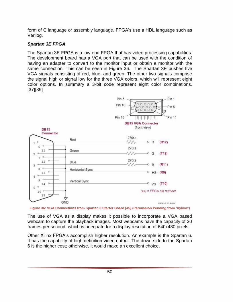
50
form of C language or assembly language. FPGA’s use a HDL language such as Verilog.
Spartan 3E FPGA
The Spartan 3E FPGA is a low-end FPGA that has video processing capabilities. The development board has a VGA port that can be used with the condition of having an adapter to convert to the monitor input or obtain a monitor with the same connection. This can be seen in Figure 36. The Spartan 3E pushes five VGA signals consisting of red, blue, and green. The other two signals comprise the signal high or signal low for the three VGA colors, which will represent eight color options. In summary a 3-bit code represent eight color combinations. [37][39]
Figure 36: VGA Connections from Spartan 3 Starter Board [45] (Permission Pending from ‘Xylilnx’)
The use of VGA as a display makes it possible to incorporate a VGA based webcam to capture the playback images. Most webcams have the capacity of 30 frames per second, which is adequate for a display resolution of 640x480 pixels.
Other Xilinx FPGA’s accomplish higher resolution. An example is the Spartan 6. It has the capability of high definition video output. The down side to the Spartan 6 is the higher cost; otherwise, it would make an excellent choice.
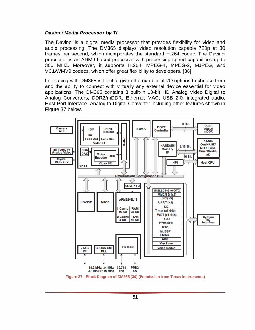
51
Davinci Media Processor by TI
The Davinci is a digital media processor that provides flexibility for video and audio processing. The DM365 displays video resolution capable 720p at 30 frames per second, which incorporates the standard H.264 codec. The Davinci processor is an ARM9-based processor with processing speed capabilities up to 300 MHZ. Moreover, it supports H.264, MPEG-4, MPEG-2, MJPEG, and VC1/WMV9 codecs, which offer great flexibility to developers. [36]
Interfacing with DM365 is flexible given the number of I/O options to choose from and the ability to connect with virtually any external device essential for video applications. The DM365 contains 3 built-in 10-bit HD Analog Video Digital to Analog Converters, DDR2/mDDR, Ethernet MAC, USB 2.0, integrated audio, Host Port Interface, Analog to Digital Converter including other features shown in Figure 37 below.
Figure 37 - Block Diagram of DM365 [36] (Permission from Texas Instruments)
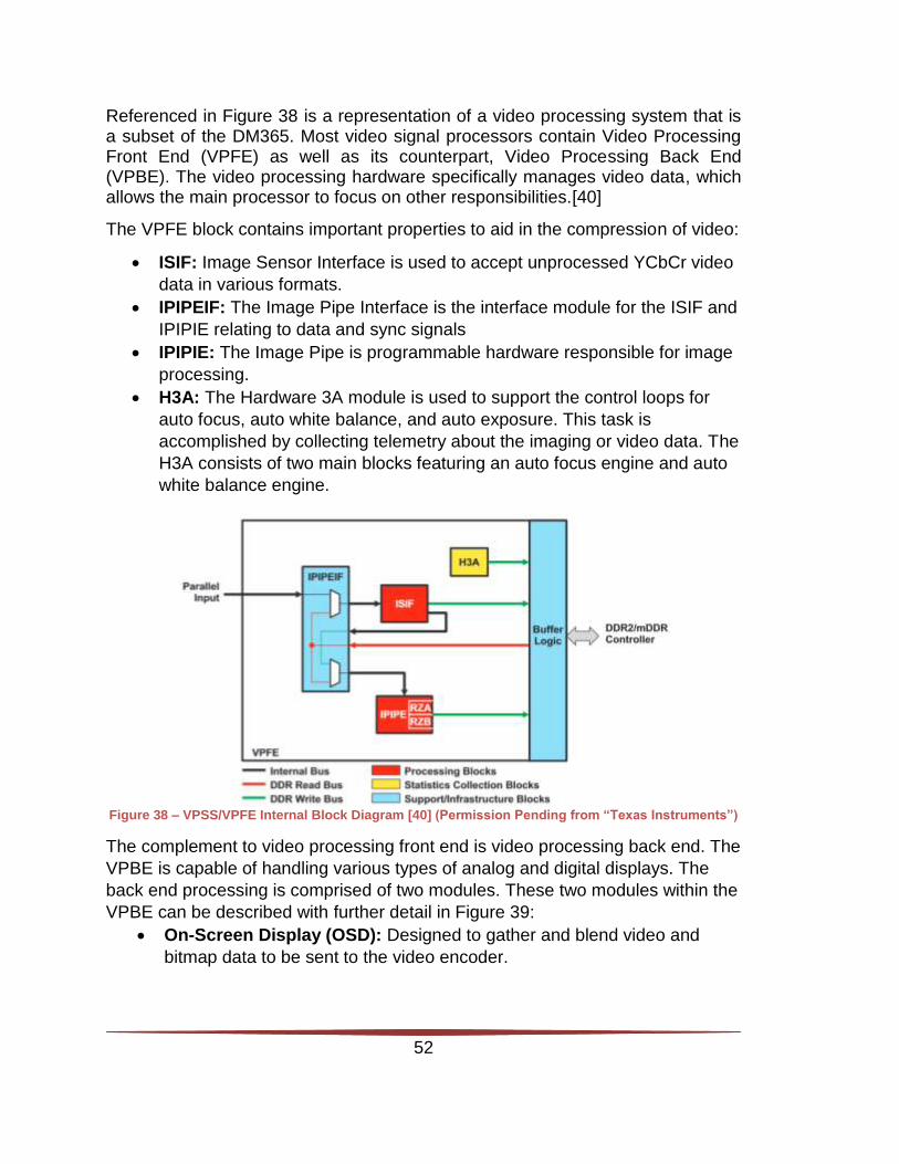
52
Referenced in Figure 38 is a representation of a video processing system that is a subset of the DM365. Most video signal processors contain Video Processing Front End (VPFE) as well as its counterpart, Video Processing Back End (VPBE). The video processing hardware specifically manages video data, which allows the main processor to focus on other responsibilities.[40]
The VPFE block contains important properties to aid in the compression of video:
ISIF: Image Sensor Interface is used to accept unprocessed YCbCr video
data in various formats.
IPIPEIF: The Image Pipe Interface is the interface module for the ISIF and
IPIPIE relating to data and sync signals
IPIPIE: The Image Pipe is programmable hardware responsible for image
processing.
H3A: The Hardware 3A module is used to support the control loops for
auto focus, auto white balance, and auto exposure. This task is
accomplished by collecting telemetry about the imaging or video data. The
H3A consists of two main blocks featuring an auto focus engine and auto
white balance engine.
Figure 38 – VPSS/VPFE Internal Block Diagram [40] (Permission Pending from “Texas Instruments”)
The complement to video processing front end is video processing back end. The
VPBE is capable of handling various types of analog and digital displays. The
back end processing is comprised of two modules. These two modules within the
VPBE can be described with further detail in Figure 39:
On-Screen Display (OSD): Designed to gather and blend video and
bitmap data to be sent to the video encoder.
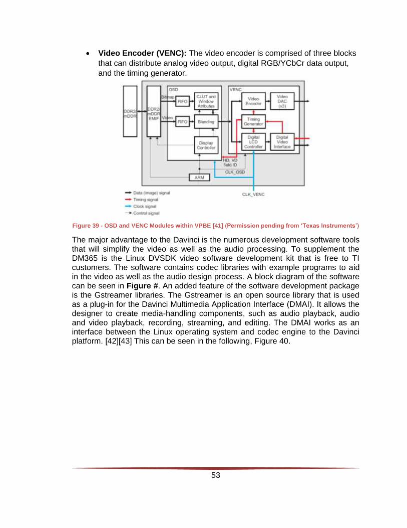
53
Video Encoder (VENC): The video encoder is comprised of three blocks
that can distribute analog video output, digital RGB/YCbCr data output,
and the timing generator.
Figure 39 - OSD and VENC Modules within VPBE [41] (Permission pending from ‘Texas Instruments’)
The major advantage to the Davinci is the numerous development software tools that will simplify the video as well as the audio processing. To supplement the DM365 is the Linux DVSDK video software development kit that is free to TI customers. The software contains codec libraries with example programs to aid in the video as well as the audio design process. A block diagram of the software can be seen in Figure #. An added feature of the software development package is the Gstreamer libraries. The Gstreamer is an open source library that is used as a plug-in for the Davinci Multimedia Application Interface (DMAI). It allows the designer to create media-handling components, such as audio playback, audio and video playback, recording, streaming, and editing. The DMAI works as an interface between the Linux operating system and codec engine to the Davinci platform. [42][43] This can be seen in the following, Figure 40.
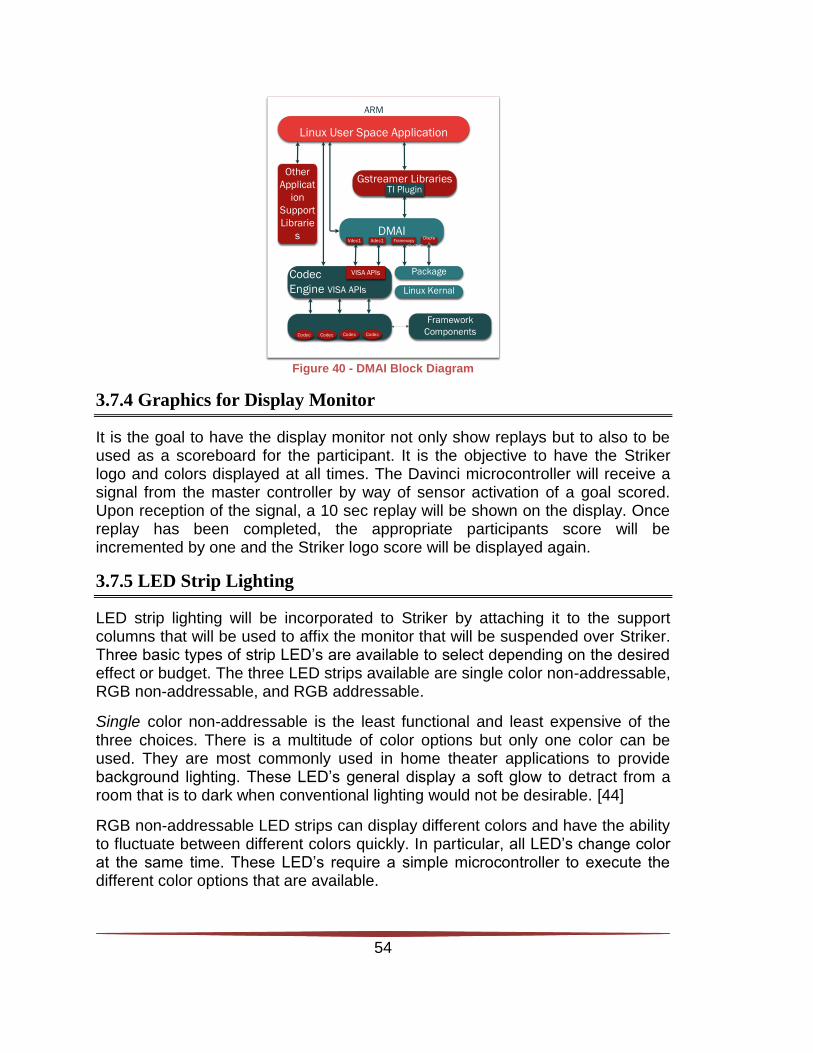
54
Linux User Space Application
ARM
Other
Applicat
ion
Support
Librarie
s
Gstreamer Libraries
DMAI
Codec
Engine VISA APIs
SOC Board
Support
Package
Linux Kernal
Codec Codec Codec Codec
Vdec1 Adec1 FramecopyDispla
y
Framework
Components
VISA APIs
TI Plugin
Figure 40 - DMAI Block Diagram
3.7.4 Graphics for Display Monitor
It is the goal to have the display monitor not only show replays but to also to be used as a scoreboard for the participant. It is the objective to have the Striker logo and colors displayed at all times. The Davinci microcontroller will receive a signal from the master controller by way of sensor activation of a goal scored. Upon reception of the signal, a 10 sec replay will be shown on the display. Once replay has been completed, the appropriate participants score will be incremented by one and the Striker logo score will be displayed again.
3.7.5 LED Strip Lighting
LED strip lighting will be incorporated to Striker by attaching it to the support columns that will be used to affix the monitor that will be suspended over Striker. Three basic types of strip LED’s are available to select depending on the desired effect or budget. The three LED strips available are single color non-addressable, RGB non-addressable, and RGB addressable.
Single color non-addressable is the least functional and least expensive of the three choices. There is a multitude of color options but only one color can be used. They are most commonly used in home theater applications to provide background lighting. These LED’s general display a soft glow to detract from a room that is to dark when conventional lighting would not be desirable. [44]
RGB non-addressable LED strips can display different colors and have the ability to fluctuate between different colors quickly. In particular, all LED’s change color at the same time. These LED’s require a simple microcontroller to execute the different color options that are available.
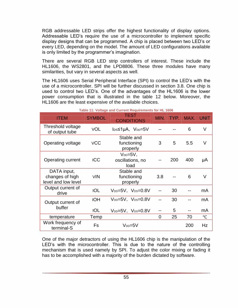
55
RGB addressable LED strips offer the highest functionality of display options. Addressable LED’s require the use of a microcontroller to implement specific display designs that can be programmed. A chip is placed between two LED’s or every LED, depending on the model. The amount of LED configurations available is only limited by the programmer’s imagination.
There are several RGB LED strip controllers of interest. These include the HL1606, the WS2801, and the LPD8806. These three modules have many similarities, but vary in several aspects as well.
The HL1606 uses Serial Peripheral Interface (SPI) to control the LED’s with the use of a microcontroller. SPI will be further discussed in section 3.8. One chip is used to control two LED’s. One of the advantages of the HL1606 is the lower power consumption that is illustrated in the table 12 below. Moreover, the HL1606 are the least expensive of the available choices.
Table 11: Voltage and Current Requirements for HL 1606
ITEM SYMBOL TEST
CONDITIONS MIN. TYP. MAX. UNIT
Threshold voltage of output tube
VOL IDS≤1μA,VDD=5V -- -- 6 V
Operating voltage VCC Stable and functioning
properly 3 5 5.5 V
Operating current ICC VDD=5V,
oscillations, no load
-- 200 400 μA
DATA input, changes of high
level and low level VIN
Stable and functioning
properly 3.8 -- 6 V
Output current of drive
IOL VDD=5V,VDS=0.8V -- 30 -- mA
Output current of buffer
IOH
IOL
VDD=5V,VDS=0.8V
VDD=5V,VDS=0.8V
--
--
30
5
--
--
mA
mA
temperature Temp 0 25 70 ℃
Work frequency of terminal-S
Fs VDD=5V 200 Hz
One of the major detractors of using the HL1606 chip is the manipulation of the LED’s with the microcontroller. This is due to the nature of the controlling mechanism that is used namely by SPI. To adjust the color mixing or fading it has to be accomplished with a majority of the burden dictated by software.
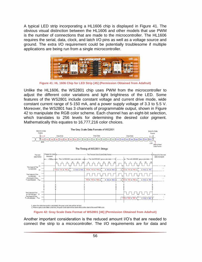
56
A typical LED strip incorporating a HL1606 chip is displayed in Figure 41. The obvious visual distinction between the HL1606 and other models that use PWM is the number of connections that are made to the microcontroller. The HL1606 requires the serial, data, clock, and latch I/O pins as well as a voltage source and ground. The extra I/O requirement could be potentially troublesome if multiple applications are being run from a single microcontroller.
Figure 41: HL 1606 Chip for LED Strip [45] (Permission Obtained from Adafruit)
Unlike the HL1606, the WS2801 chip uses PWM from the microcontroller to adjust the different color variations and light brightness of the LED. Some features of the WS2801 include constant voltage and current drive mode, wide constant current range of 5-150 mA, and a power supply voltage of 3.3 to 5.5 V. Moreover, the WS2801 has 3 channels of programmable output, shown in Figure 42 to manipulate the RGB color scheme. Each channel has an eight-bit selection, which translates to 256 levels for determining the desired color pigment. Mathematically this equates to 16,777,216 color choices.
Figure 42: Gray Scale Data Format of WS2801 [46] (Permission Obtained from Adafruit)
Another important consideration is the reduced amount I/O’s that are needed to connect the strip to a microcontroller. The I/O requirements are for data and
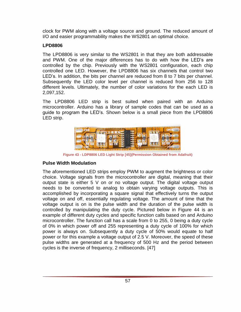
57
clock for PWM along with a voltage source and ground. The reduced amount of I/O and easier programmability makes the WS2801 an optimal choice.
LPD8806
The LPD8806 is very similar to the WS2801 in that they are both addressable and PWM. One of the major differences has to do with how the LED’s are controlled by the chip. Previously with the WS2801 configuration, each chip controlled one LED. However, the LPD8806 has six channels that control two LED’s. In addition, the bits per channel are reduced from 8 to 7 bits per channel. Subsequently the LED color level per channel is reduced from 256 to 128 different levels. Ultimately, the number of color variations for the each LED is 2,097,152.
The LPD8806 LED strip is best suited when paired with an Arduino microcontroller. Arduino has a library of sample codes that can be used as a guide to program the LED’s. Shown below is a small piece from the LPD8806 LED strip.
Figure 43 - LDP8806 LED Light Strip [45](Permission Obtained from Adafruit)
Pulse Width Modulation
The aforementioned LED strips employ PWM to augment the brightness or color choice. Voltage signals from the microcontroller are digital, meaning that their output state is either 5 V on or no voltage output. The digital voltage output needs to be converted to analog to obtain varying voltage outputs. This is accomplished by incorporating a square signal that effectively turns the output voltage on and off, essentially regulating voltage. The amount of time that the voltage output is on is the pulse width and the duration of the pulse width is controlled by manipulating the duty cycle. Pictured below in Figure 44 is an example of different duty cycles and specific function calls based on and Arduino microcontroller. The function call has a scale from 0 to 255, 0 being a duty cycle of 0% in which power off and 255 representing a duty cycle of 100% for which power is always on. Subsequently a duty cycle of 50% would equate to half power or for this example a voltage output of 2.5 V. Moreover, the speed of these pulse widths are generated at a frequency of 500 Hz and the period between cycles is the inverse of frequency, 2 milliseconds. [47]
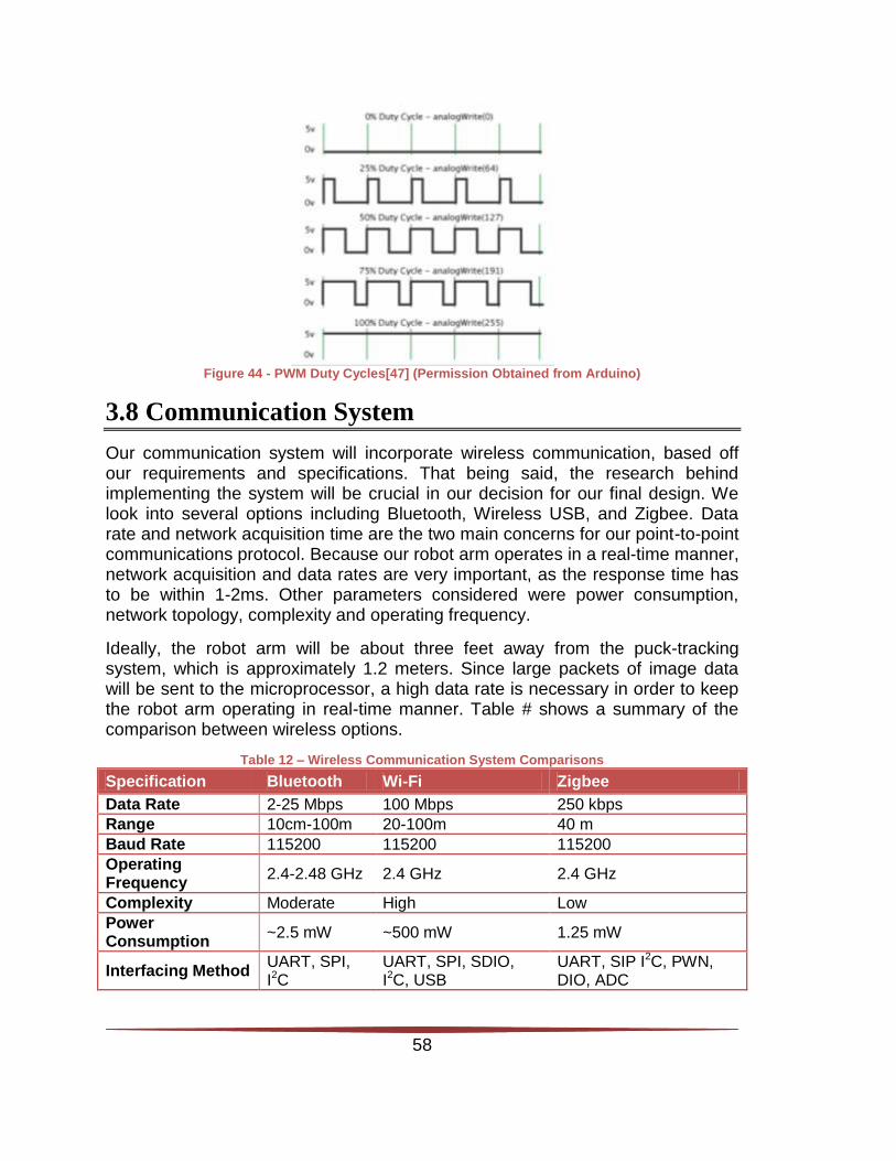
58
Figure 44 - PWM Duty Cycles[47] (Permission Obtained from Arduino)
3.8 Communication System
Our communication system will incorporate wireless communication, based off our requirements and specifications. That being said, the research behind implementing the system will be crucial in our decision for our final design. We look into several options including Bluetooth, Wireless USB, and Zigbee. Data rate and network acquisition time are the two main concerns for our point-to-point communications protocol. Because our robot arm operates in a real-time manner, network acquisition and data rates are very important, as the response time has to be within 1-2ms. Other parameters considered were power consumption, network topology, complexity and operating frequency.
Ideally, the robot arm will be about three feet away from the puck-tracking system, which is approximately 1.2 meters. Since large packets of image data will be sent to the microprocessor, a high data rate is necessary in order to keep the robot arm operating in real-time manner. Table # shows a summary of the comparison between wireless options.
Table 12 – Wireless Communication System Comparisons
Specification Bluetooth Wi-Fi Zigbee
Data Rate 2-25 Mbps 100 Mbps 250 kbps
Range 10cm-100m 20-100m 40 m
Baud Rate 115200 115200 115200
Operating Frequency
2.4-2.48 GHz 2.4 GHz 2.4 GHz
Complexity Moderate High Low
Power Consumption
~2.5 mW ~500 mW 1.25 mW
Interfacing Method UART, SPI, I2C
UART, SPI, SDIO, I2C, USB
UART, SIP I2C, PWN, DIO, ADC
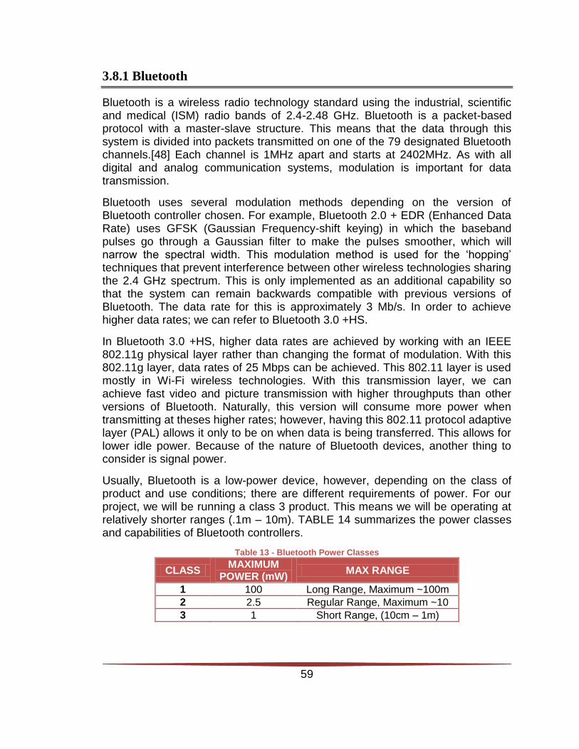
59
3.8.1 Bluetooth
Bluetooth is a wireless radio technology standard using the industrial, scientific and medical (ISM) radio bands of 2.4-2.48 GHz. Bluetooth is a packet-based protocol with a master-slave structure. This means that the data through this system is divided into packets transmitted on one of the 79 designated Bluetooth channels.[48] Each channel is 1MHz apart and starts at 2402MHz. As with all digital and analog communication systems, modulation is important for data transmission.
Bluetooth uses several modulation methods depending on the version of Bluetooth controller chosen. For example, Bluetooth 2.0 + EDR (Enhanced Data Rate) uses GFSK (Gaussian Frequency-shift keying) in which the baseband pulses go through a Gaussian filter to make the pulses smoother, which will narrow the spectral width. This modulation method is used for the ‘hopping’ techniques that prevent interference between other wireless technologies sharing the 2.4 GHz spectrum. This is only implemented as an additional capability so that the system can remain backwards compatible with previous versions of Bluetooth. The data rate for this is approximately 3 Mb/s. In order to achieve higher data rates; we can refer to Bluetooth 3.0 +HS.
In Bluetooth 3.0 +HS, higher data rates are achieved by working with an IEEE 802.11g physical layer rather than changing the format of modulation. With this 802.11g layer, data rates of 25 Mbps can be achieved. This 802.11 layer is used mostly in Wi-Fi wireless technologies. With this transmission layer, we can achieve fast video and picture transmission with higher throughputs than other versions of Bluetooth. Naturally, this version will consume more power when transmitting at theses higher rates; however, having this 802.11 protocol adaptive layer (PAL) allows it only to be on when data is being transferred. This allows for lower idle power. Because of the nature of Bluetooth devices, another thing to consider is signal power.
Usually, Bluetooth is a low-power device, however, depending on the class of product and use conditions; there are different requirements of power. For our project, we will be running a class 3 product. This means we will be operating at relatively shorter ranges (.1m – 10m). TABLE 14 summarizes the power classes and capabilities of Bluetooth controllers.
Table 13 - Bluetooth Power Classes
CLASS MAXIMUM
POWER (mW) MAX RANGE
1 100 Long Range, Maximum ~100m
2 2.5 Regular Range, Maximum ~10
3 1 Short Range, (10cm – 1m)
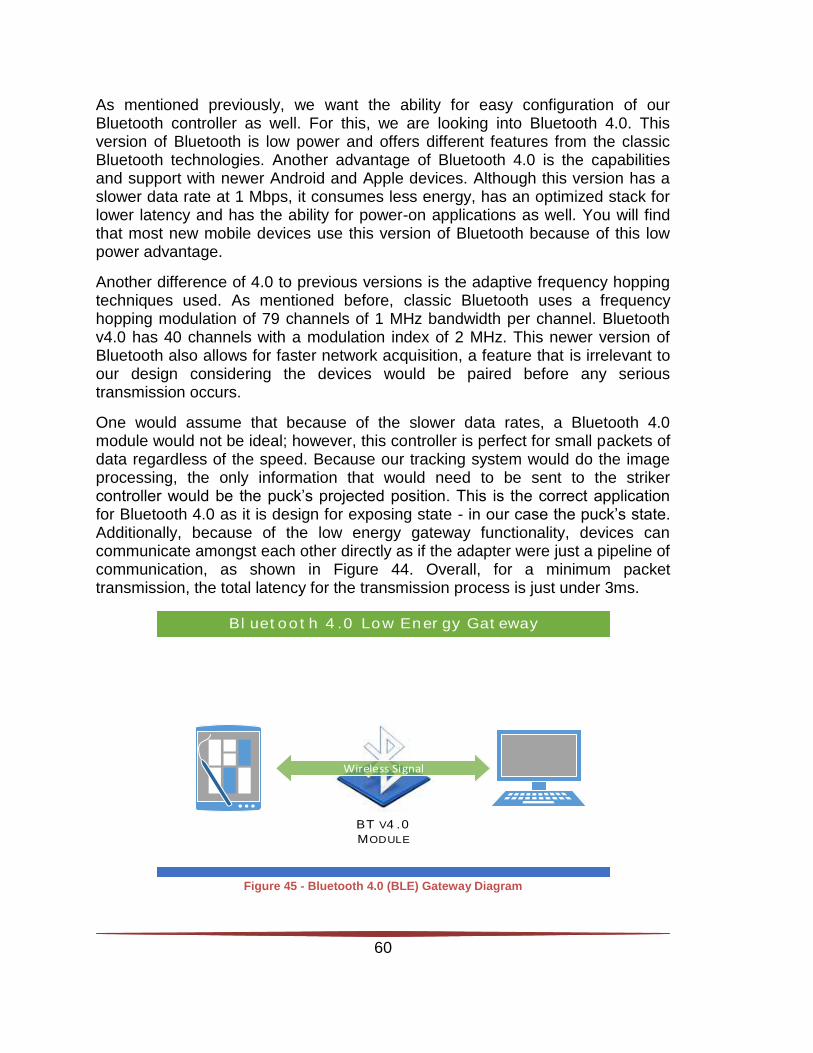
60
As mentioned previously, we want the ability for easy configuration of our Bluetooth controller as well. For this, we are looking into Bluetooth 4.0. This version of Bluetooth is low power and offers different features from the classic Bluetooth technologies. Another advantage of Bluetooth 4.0 is the capabilities and support with newer Android and Apple devices. Although this version has a slower data rate at 1 Mbps, it consumes less energy, has an optimized stack for lower latency and has the ability for power-on applications as well. You will find that most new mobile devices use this version of Bluetooth because of this low power advantage.
Another difference of 4.0 to previous versions is the adaptive frequency hopping techniques used. As mentioned before, classic Bluetooth uses a frequency hopping modulation of 79 channels of 1 MHz bandwidth per channel. Bluetooth v4.0 has 40 channels with a modulation index of 2 MHz. This newer version of Bluetooth also allows for faster network acquisition, a feature that is irrelevant to our design considering the devices would be paired before any serious transmission occurs.
One would assume that because of the slower data rates, a Bluetooth 4.0 module would not be ideal; however, this controller is perfect for small packets of data regardless of the speed. Because our tracking system would do the image processing, the only information that would need to be sent to the striker controller would be the puck’s projected position. This is the correct application for Bluetooth 4.0 as it is design for exposing state - in our case the puck’s state. Additionally, because of the low energy gateway functionality, devices can communicate amongst each other directly as if the adapter were just a pipeline of communication, as shown in Figure 44. Overall, for a minimum packet transmission, the total latency for the transmission process is just under 3ms.
Bl uet oo t h 4 .0 Low Ener gy Gat eway
BT V4 .0
MODULE
Wireless Signal
Figure 45 - Bluetooth 4.0 (BLE) Gateway Diagram
61
3.8.2 Wireless Fidelity (Wi-Fi)
Wireless Fidelity (Wi-Fi) is another wireless technology considered for our project. Wi-Fi works by sending data wirelessly through radio frequency (RF), much like Bluetooth. It carries many advantages over any wireless communication mainly in transmission rate, range and security. Wi-Fi works off an IEEE 802.11 standard to obtain high data rates.
Throughout recent years, advancements in Wi-Fi technology have allowed for virtually limitless speeds in data rates. For example, 802.11n transmits at higher rates than earlier version, 802.11a. Wi-Fi runs on the same ISM band as Bluetooth of 2.4 GHz. Just as a basic understanding of the significant speed difference from Bluetooth technologies, one of the earlier versions of Wi-Fi, 802.11a, provides speeds of up to 54-Mbps.
Although there are differences between Bluetooth and Wi-Fi, they are to some extent, complimentary to each other in their applications. One of the main differences is that Wi-Fi is intended as a wireless solution of local area networks, while Bluetooth is intended for device-to-device connection. Wi-Fi is connected asymmetrically via a central access point.
3.8.3 Zigbee
Zigbee is another type of Wireless Personal Area Network (WPAN) that operates on the IEEE 802.15 standard. It operates in the same ISM band as Wi-Fi and Bluetooth of 2.4 GHz. It is a smaller, simpler way to communicate and built from low-power digital radios. This compact design makes it ideal in our application for its energy efficiency. The transmission range varies from as little as 10 m but can extend to further ranges via mesh networks.
Because of its decentralized nature and non-centralized control, the lack of a high power transmitter/receiver can only transmit data at approximately 250 kbps. This low transmission rate is ideal for applications pertaining to sensor signals or very small data packets. Advantages of this WPAN over Bluetooth or Wi-Fi are cost and simplicity.
3.8.4 Interfacing with System Controllers
Universal Asynchronous Receiver/Transmitter (UART):
Perhaps the most common and widely used protocol of the various types is the Universal Asynchronous Receiver/Transmitter (UART). In UART transmission, data is sent in 8-bit packets that include start and stop bits, and in some instances a parity bit that will be used to check for transmission errors. Usually, UART connections use four ports for data transmission: Transmit (TX), Receive (Rx), Clear to send (CTS), Ready to send (RTS), much like RS232
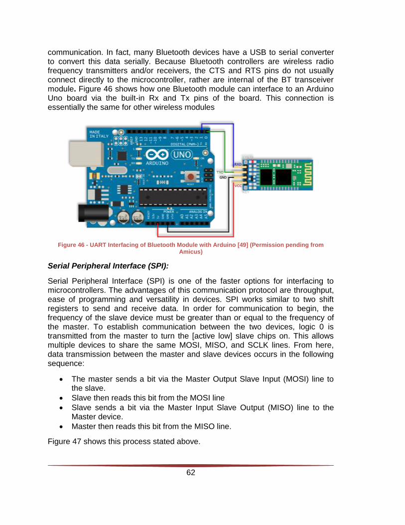
62
communication. In fact, many Bluetooth devices have a USB to serial converter to convert this data serially. Because Bluetooth controllers are wireless radio frequency transmitters and/or receivers, the CTS and RTS pins do not usually connect directly to the microcontroller, rather are internal of the BT transceiver module. Figure 46 shows how one Bluetooth module can interface to an Arduino Uno board via the built-in Rx and Tx pins of the board. This connection is essentially the same for other wireless modules
Figure 46 - UART Interfacing of Bluetooth Module with Arduino [49] (Permission pending from
Amicus)
Serial Peripheral Interface (SPI):
Serial Peripheral Interface (SPI) is one of the faster options for interfacing to microcontrollers. The advantages of this communication protocol are throughput, ease of programming and versatility in devices. SPI works similar to two shift registers to send and receive data. In order for communication to begin, the frequency of the slave device must be greater than or equal to the frequency of the master. To establish communication between the two devices, logic 0 is transmitted from the master to turn the [active low] slave chips on. This allows multiple devices to share the same MOSI, MISO, and SCLK lines. From here, data transmission between the master and slave devices occurs in the following sequence:
The master sends a bit via the Master Output Slave Input (MOSI) line to the slave.
Slave then reads this bit from the MOSI line
Slave sends a bit via the Master Input Slave Output (MISO) line to the Master device.
Master then reads this bit from the MISO line.
Figure 47 shows this process stated above.
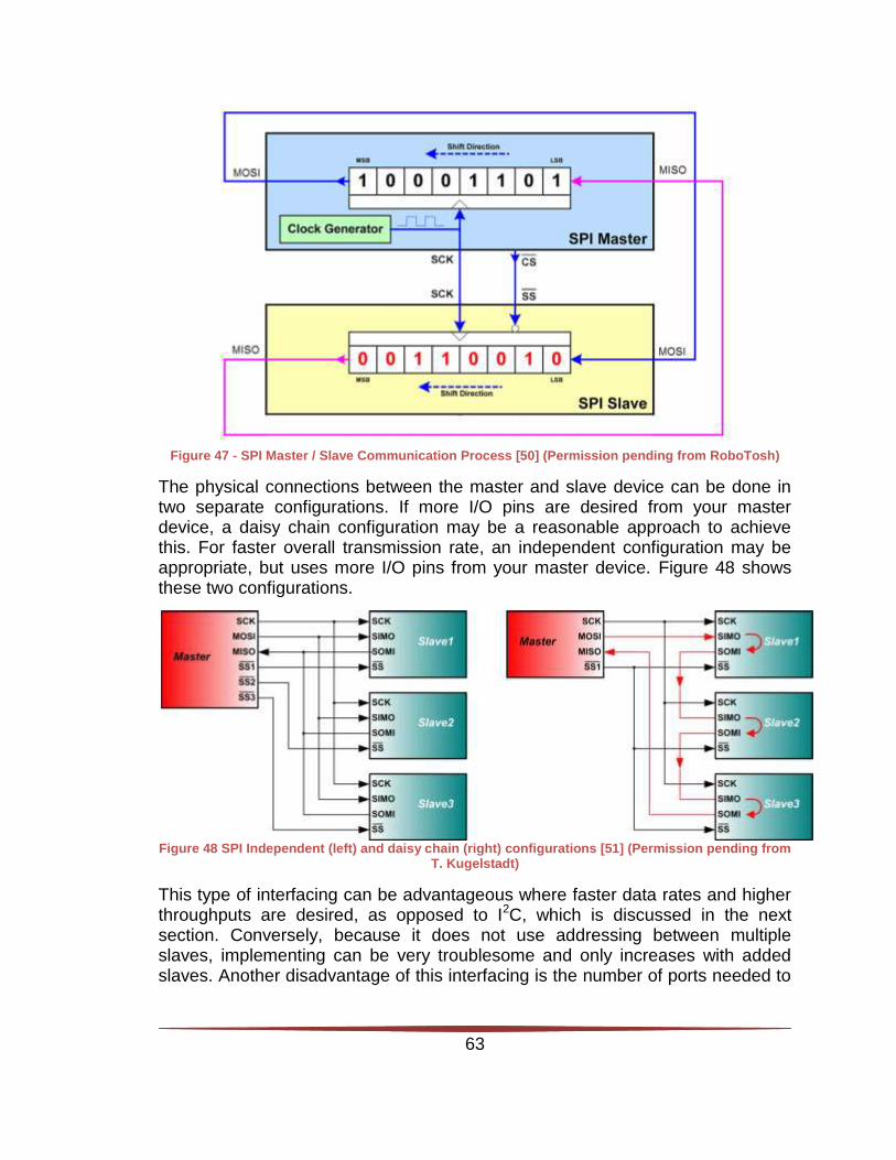
63
Figure 47 - SPI Master / Slave Communication Process [50] (Permission pending from RoboTosh)
The physical connections between the master and slave device can be done in two separate configurations. If more I/O pins are desired from your master device, a daisy chain configuration may be a reasonable approach to achieve this. For faster overall transmission rate, an independent configuration may be appropriate, but uses more I/O pins from your master device. Figure 48 shows these two configurations.
Figure 48 SPI Independent (left) and daisy chain (right) configurations [51] (Permission pending from
T. Kugelstadt)
This type of interfacing can be advantageous where faster data rates and higher throughputs are desired, as opposed to I2C, which is discussed in the next section. Conversely, because it does not use addressing between multiple slaves, implementing can be very troublesome and only increases with added slaves. Another disadvantage of this interfacing is the number of ports needed to
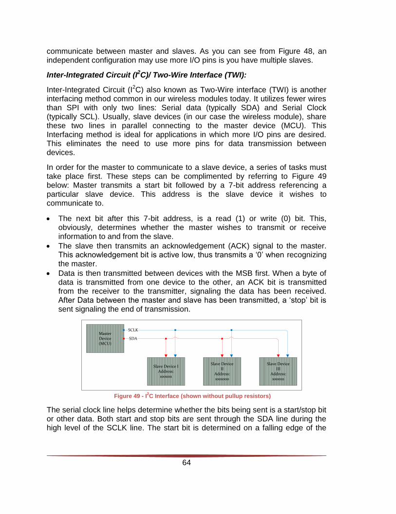
64
communicate between master and slaves. As you can see from Figure 48, an independent configuration may use more I/O pins is you have multiple slaves.
Inter-Integrated Circuit (I2C)/ Two-Wire Interface (TWI):
Inter-Integrated Circuit (I2C) also known as Two-Wire interface (TWI) is another interfacing method common in our wireless modules today. It utilizes fewer wires than SPI with only two lines: Serial data (typically SDA) and Serial Clock (typically SCL). Usually, slave devices (in our case the wireless module), share these two lines in parallel connecting to the master device (MCU). This Interfacing method is ideal for applications in which more I/O pins are desired. This eliminates the need to use more pins for data transmission between devices.
In order for the master to communicate to a slave device, a series of tasks must take place first. These steps can be complimented by referring to Figure 49 below: Master transmits a start bit followed by a 7-bit address referencing a particular slave device. This address is the slave device it wishes to communicate to.
The next bit after this 7-bit address, is a read (1) or write (0) bit. This, obviously, determines whether the master wishes to transmit or receive information to and from the slave.
The slave then transmits an acknowledgement (ACK) signal to the master. This acknowledgement bit is active low, thus transmits a ‘0’ when recognizing the master.
Data is then transmitted between devices with the MSB first. When a byte of data is transmitted from one device to the other, an ACK bit is transmitted from the receiver to the transmitter, signaling the data has been received. After Data between the master and slave has been transmitted, a ‘stop’ bit is sent signaling the end of transmission.
MasterDevice(MCU)
Slave Device IAddress:1001011
Slave Device II
Address:1001000
Slave Device III
Address:1000111
SDA
SCLK
Figure 49 - I
2C Interface (shown without pullup resistors)
The serial clock line helps determine whether the bits being sent is a start/stop bit or other data. Both start and stop bits are sent through the SDA line during the high level of the SCLK line. The start bit is determined on a falling edge of the
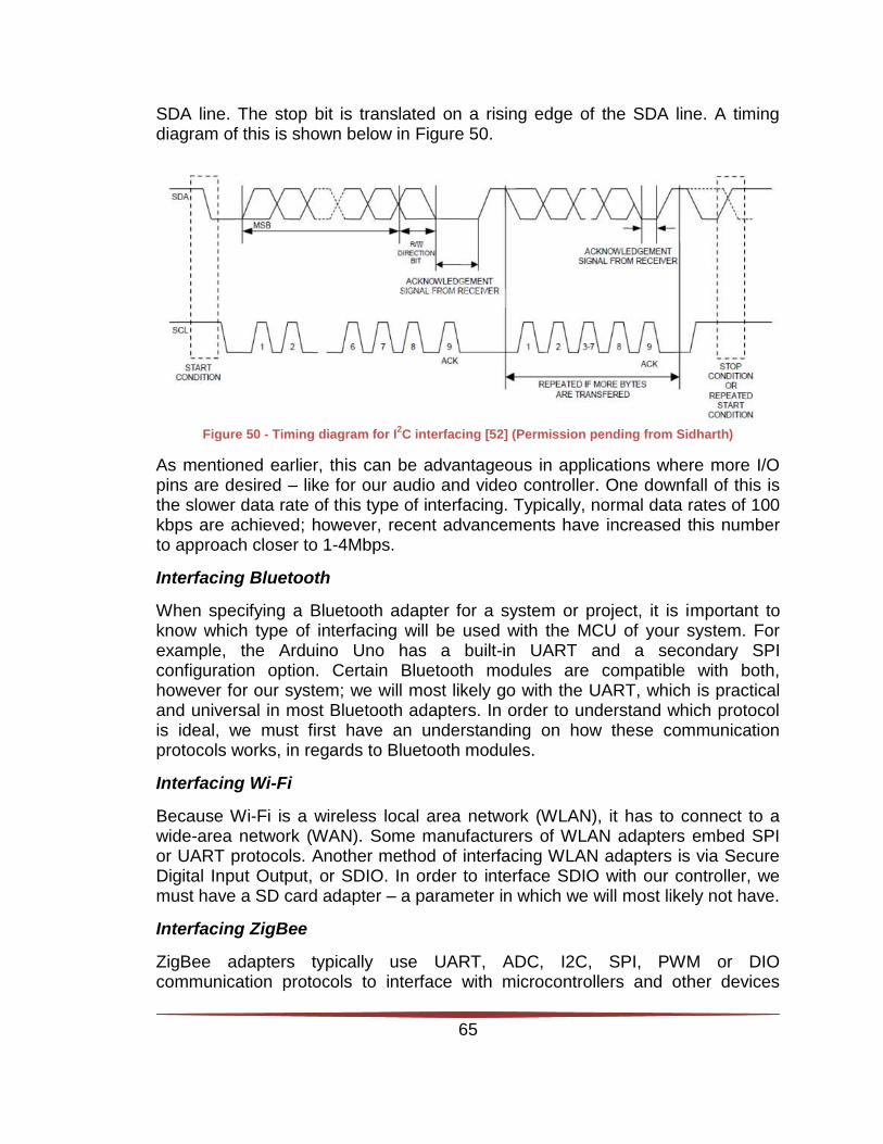
65
SDA line. The stop bit is translated on a rising edge of the SDA line. A timing diagram of this is shown below in Figure 50.
Figure 50 - Timing diagram for I
2C interfacing [52] (Permission pending from Sidharth)
As mentioned earlier, this can be advantageous in applications where more I/O pins are desired – like for our audio and video controller. One downfall of this is the slower data rate of this type of interfacing. Typically, normal data rates of 100 kbps are achieved; however, recent advancements have increased this number to approach closer to 1-4Mbps.
Interfacing Bluetooth
When specifying a Bluetooth adapter for a system or project, it is important to know which type of interfacing will be used with the MCU of your system. For example, the Arduino Uno has a built-in UART and a secondary SPI configuration option. Certain Bluetooth modules are compatible with both, however for our system; we will most likely go with the UART, which is practical and universal in most Bluetooth adapters. In order to understand which protocol is ideal, we must first have an understanding on how these communication protocols works, in regards to Bluetooth modules.
Interfacing Wi-Fi
Because Wi-Fi is a wireless local area network (WLAN), it has to connect to a wide-area network (WAN). Some manufacturers of WLAN adapters embed SPI or UART protocols. Another method of interfacing WLAN adapters is via Secure Digital Input Output, or SDIO. In order to interface SDIO with our controller, we must have a SD card adapter – a parameter in which we will most likely not have.
Interfacing ZigBee
ZigBee adapters typically use UART, ADC, I2C, SPI, PWM or DIO communication protocols to interface with microcontrollers and other devices
66
(depending on model). As mentioned previously, it operates in the ISM band frequency of 2.4 GHz, thus maximum transmission rate is approximately 250 kbps.
3.8.3 Software
To create communication between the smart phone and Striker, we must use a wireless communication standard. Two standards that are commonly used with smart phones are Bluetooth and Wi-Fi. The path data will take is between the microcontroller, the wireless communication shield, and the smart phone. From the smart phones perspective, it must have the ability to transmit data through the wireless communication standard we choose to the shield being used by the microcontroller. Therefore, the software written must be able to transmit data through the wireless communication that we choose.
The software must first have the ability to store user names, stats, and scores for long term. By long term, we mean that the data must not be erased after the application is closed. It must remain saved permanently. Additionally, it must have the ability to trigger the game to begin. Once the game begins, the application must listen to Striker and differentiate when a goal is scored versus regular gameplay. When a goal is scored, it must have the ability to display data sent from the robotic arm and video from the AV system, if the user chooses they want to save the replay. The application must also have the ability to realize when the game is over, and decide if the user has reached leader board status. In addition, it must have the capability of displaying all final stats to the player.
3.9 System Microcontroller
Microcontrollers are present in almost all electronic devices these days, basically any product or device that interacts with its user has a microcontroller inside. For example: LED or LCD, digital cameras, cell phones, camcorders, answering machines, laser printers, telephones , anti-lock brakes, the cruise control and so on. Any device that has a remote control almost certainly contains a microcontroller: TVs, VCRs and stereo systems all fall into this category.
3.9.1 T.I. MSP430FG4618
For this project, we will be using two Microcontrollers one for the robot arm design and the other one to control the rest of the features in the hockey table. We have researched microcontrollers from two different providers; Texas Instrument (TI) and Arduino.
At first, we looked into MSP430G48 from TI (Texas Instrument) website since we are more familiar with it and we used it in different projects in our Embedded System class.
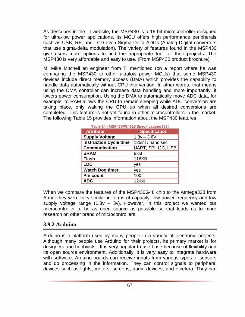
67
As describes in the TI website, the MSP430 is a 16-bit microcontroller designed for ultra-low power applications. Its MCU offers high performance peripherals such as USB, RF, and LCD even Sigma-Delta ADCs (Analog Digital converters that use sigma-delta modulation). The variety of features found in the MSP430 give users more options to find the appropriate tool for their projects. The MSP430 is very affordable and easy to use. (From MSP430 product brochure)
M. Mike Mitchell an engineer from TI mentioned (on a report where he was comparing the MSP430 to other ultralow power MCUs) that some MSP430 devices include direct memory access (DMA) which provides the capability to handle data automatically without CPU intervention. In other words, that means using the DMA controller can increase data handling and more importantly, it lowers power consumption. Using the DMA to automatically move ADC data, for example, to RAM allows the CPU to remain sleeping while ADC conversion are taking place, only waking the CPU up when all desired conversions are completed. This feature is not yet found in other microcontrollers in the market. The following Table 15 provides information about the MSP430 features.
Table 14 - MSP430FG4618 Specifications [53]
Attribute Specification
Supply Voltage 1.8v – 3.6V
Instruction Cycle time 125int / nano sec
Communication UART, SPI, I2C, USB
SRAM 8KB
Flash 116KB
LDC yes
Watch Dog timer yes
Pin count 100
ADC 12-bit
When we compare the features of the MSP430G48 chip to the Atmega328 from Atmel they were very similar in terms of capacity, low power frequency and low supply voltage range (1.8v – 3v). However, in this project we wanted our microcontroller to be as open source as possible so that leads us to more research on other brand of microcontrollers.
3.9.2 Arduino
Arduino is a platform used by many people in a variety of electronic projects. Although many people use Arduino for their projects, its primary market is for designers and hobbyists. It is very popular to use base because of flexibility and its open source environment. Additionally, it is very easy to integrate hardware with software. Arduino boards can receive inputs from various types of sensors and do processing in the information. They can control signals to peripheral devices such as lights, motors, screens, audio devices, and etcetera. They can
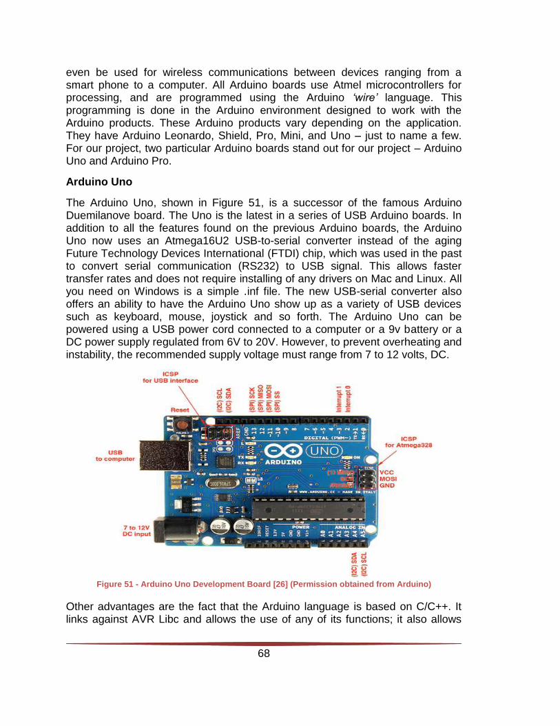
68
even be used for wireless communications between devices ranging from a smart phone to a computer. All Arduino boards use Atmel microcontrollers for processing, and are programmed using the Arduino ‘wire’ language. This programming is done in the Arduino environment designed to work with the Arduino products. These Arduino products vary depending on the application. They have Arduino Leonardo, Shield, Pro, Mini, and Uno – just to name a few. For our project, two particular Arduino boards stand out for our project – Arduino Uno and Arduino Pro.
Arduino Uno
The Arduino Uno, shown in Figure 51, is a successor of the famous Arduino Duemilanove board. The Uno is the latest in a series of USB Arduino boards. In addition to all the features found on the previous Arduino boards, the Arduino Uno now uses an Atmega16U2 USB-to-serial converter instead of the aging Future Technology Devices International (FTDI) chip, which was used in the past to convert serial communication (RS232) to USB signal. This allows faster transfer rates and does not require installing of any drivers on Mac and Linux. All you need on Windows is a simple .inf file. The new USB-serial converter also offers an ability to have the Arduino Uno show up as a variety of USB devices such as keyboard, mouse, joystick and so forth. The Arduino Uno can be powered using a USB power cord connected to a computer or a 9v battery or a DC power supply regulated from 6V to 20V. However, to prevent overheating and instability, the recommended supply voltage must range from 7 to 12 volts, DC.
Figure 51 - Arduino Uno Development Board [26] (Permission obtained from Arduino)
Other advantages are the fact that the Arduino language is based on C/C++. It links against AVR Libc and allows the use of any of its functions; it also allows
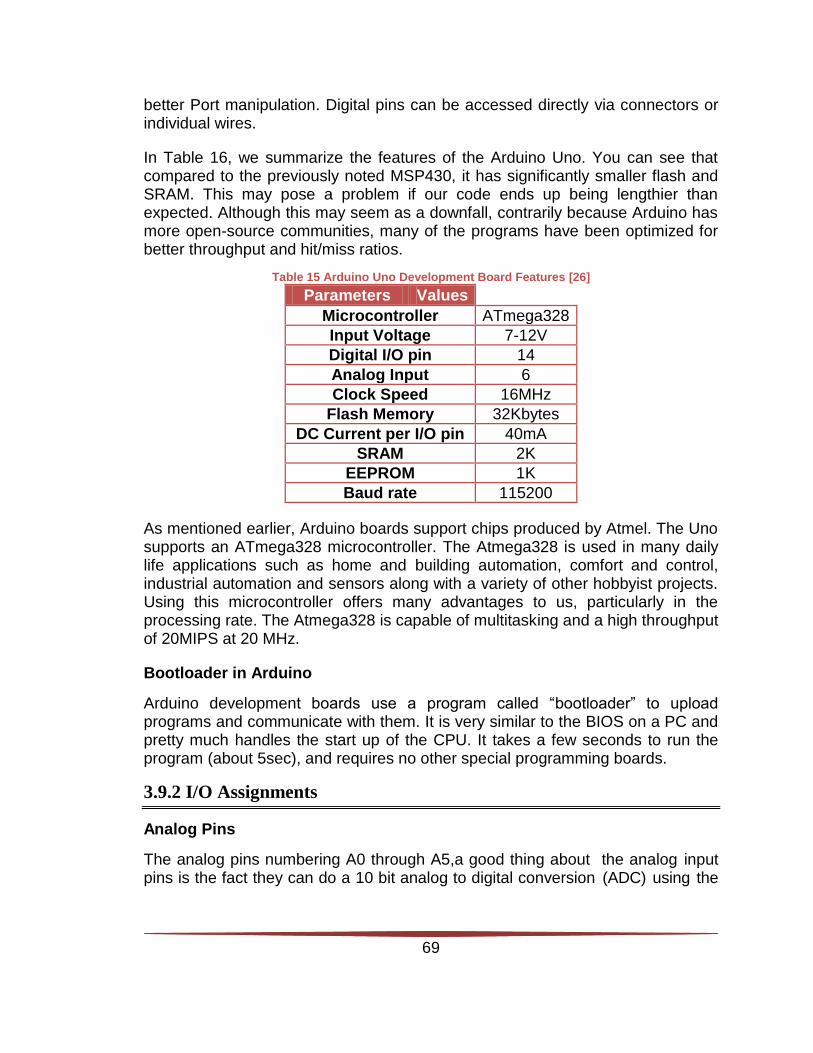
69
better Port manipulation. Digital pins can be accessed directly via connectors or individual wires.
In Table 16, we summarize the features of the Arduino Uno. You can see that compared to the previously noted MSP430, it has significantly smaller flash and SRAM. This may pose a problem if our code ends up being lengthier than expected. Although this may seem as a downfall, contrarily because Arduino has more open-source communities, many of the programs have been optimized for better throughput and hit/miss ratios.
Table 15 Arduino Uno Development Board Features [26]
Parameters Values
Microcontroller ATmega328
Input Voltage 7-12V
Digital I/O pin 14
Analog Input 6
Clock Speed 16MHz
Flash Memory 32Kbytes
DC Current per I/O pin 40mA
SRAM 2K
EEPROM 1K
Baud rate 115200
As mentioned earlier, Arduino boards support chips produced by Atmel. The Uno supports an ATmega328 microcontroller. The Atmega328 is used in many daily life applications such as home and building automation, comfort and control, industrial automation and sensors along with a variety of other hobbyist projects. Using this microcontroller offers many advantages to us, particularly in the processing rate. The Atmega328 is capable of multitasking and a high throughput of 20MIPS at 20 MHz.
Bootloader in Arduino
Arduino development boards use a program called “bootloader” to upload programs and communicate with them. It is very similar to the BIOS on a PC and pretty much handles the start up of the CPU. It takes a few seconds to run the program (about 5sec), and requires no other special programming boards.
3.9.2 I/O Assignments
Analog Pins
The analog pins numbering A0 through A5,a good thing about the analog input pins is the fact they can do a 10 bit analog to digital conversion (ADC) using the
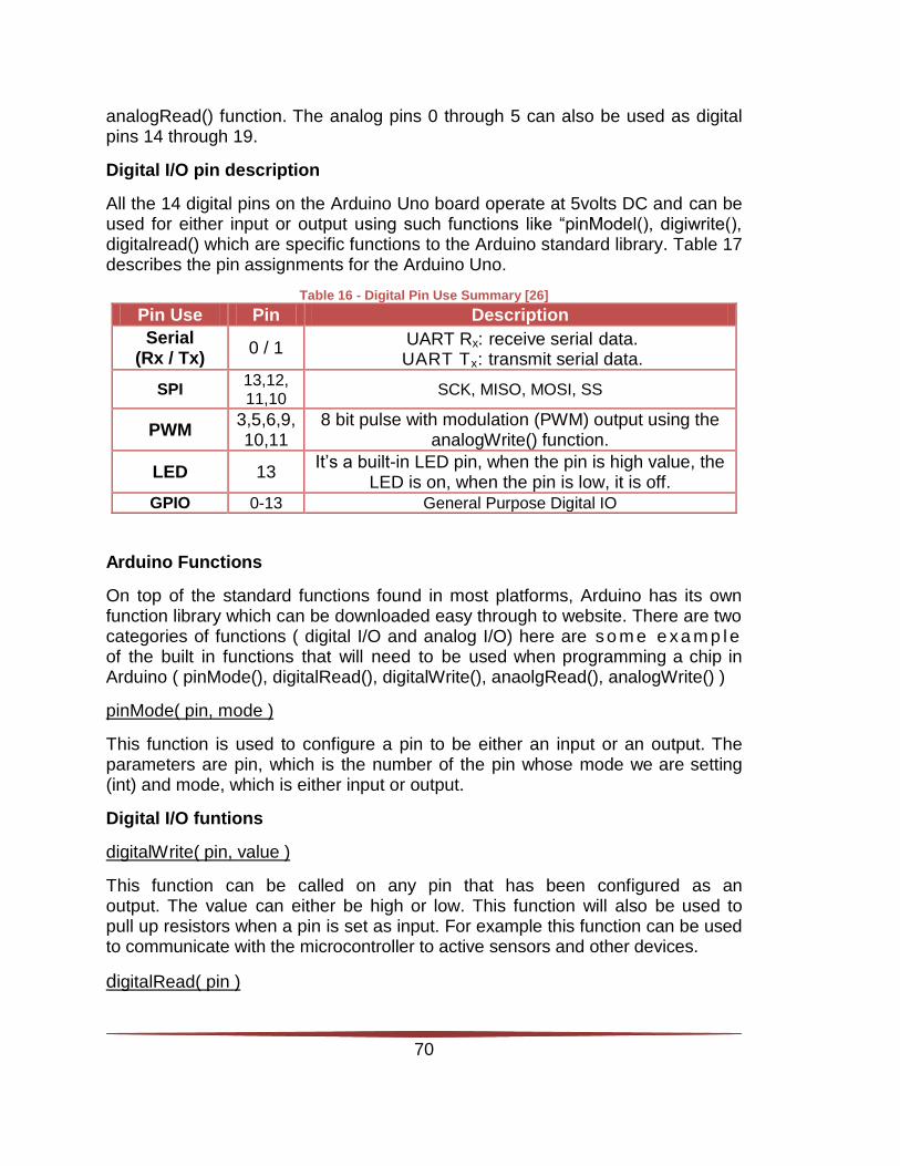
70
analogRead() function. The analog pins 0 through 5 can also be used as digital pins 14 through 19.
Digital I/O pin description
All the 14 digital pins on the Arduino Uno board operate at 5volts DC and can be used for either input or output using such functions like “pinModel(), digiwrite(), digitalread() which are specific functions to the Arduino standard library. Table 17 describes the pin assignments for the Arduino Uno.
Table 16 - Digital Pin Use Summary [26]
Pin Use Pin Description
Serial (Rx / Tx)
0 / 1 UART Rx: receive serial data. UART Tx: transmit serial data.
SPI 13,12, 11,10
SCK, MISO, MOSI, SS
PWM 3,5,6,9,10,11
8 bit pulse with modulation (PWM) output using the analogWrite() function.
LED 13 It’s a built-in LED pin, when the pin is high value, the
LED is on, when the pin is low, it is off. GPIO 0-13 General Purpose Digital IO
Arduino Functions
On top of the standard functions found in most platforms, Arduino has its own function library which can be downloaded easy through to website. There are two categories of functions ( digital I/O and analog I/O) here are so m e e xa m p l e of the built in functions that will need to be used when programming a chip in Arduino ( pinMode(), digitalRead(), digitalWrite(), anaolgRead(), analogWrite() )
pinMode( pin, mode )
This function is used to configure a pin to be either an input or an output. The parameters are pin, which is the number of the pin whose mode we are setting (int) and mode, which is either input or output.
Digital I/O funtions
digitalWrite( pin, value )
This function can be called on any pin that has been configured as an output. The value can either be high or low. This function will also be used to pull up resistors when a pin is set as input. For example this function can be used to communicate with the microcontroller to active sensors and other devices.
digitalRead( pin )
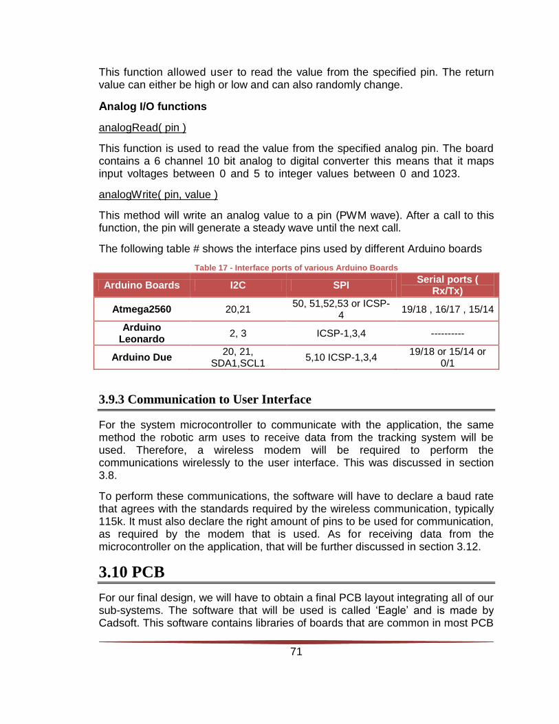
71
This function allowed user to read the value from the specified pin. The return value can either be high or low and can also randomly change.
Analog I/O functions
analogRead( pin )
This function is used to read the value from the specified analog pin. The board contains a 6 channel 10 bit analog to digital converter this means that it maps input voltages between 0 and 5 to integer values between 0 and 1023.
analogWrite( pin, value )
This method will write an analog value to a pin (PWM wave). After a call to this function, the pin will generate a steady wave until the next call.
The following table # shows the interface pins used by different Arduino boards
Table 17 - Interface ports of various Arduino Boards
Arduino Boards I2C SPI Serial ports (
Rx/Tx)
Atmega2560 20,21 50, 51,52,53 or ICSP-
4 19/18 , 16/17 , 15/14
Arduino Leonardo
2, 3 ICSP-1,3,4 ----------
Arduino Due 20, 21,
SDA1,SCL1 5,10 ICSP-1,3,4
19/18 or 15/14 or 0/1
3.9.3 Communication to User Interface
For the system microcontroller to communicate with the application, the same method the robotic arm uses to receive data from the tracking system will be used. Therefore, a wireless modem will be required to perform the communications wirelessly to the user interface. This was discussed in section 3.8.
To perform these communications, the software will have to declare a baud rate that agrees with the standards required by the wireless communication, typically 115k. It must also declare the right amount of pins to be used for communication, as required by the modem that is used. As for receiving data from the microcontroller on the application, that will be further discussed in section 3.12.
3.10 PCB
For our final design, we will have to obtain a final PCB layout integrating all of our sub-systems. The software that will be used is called ‘Eagle’ and is made by Cadsoft. This software contains libraries of boards that are common in most PCB
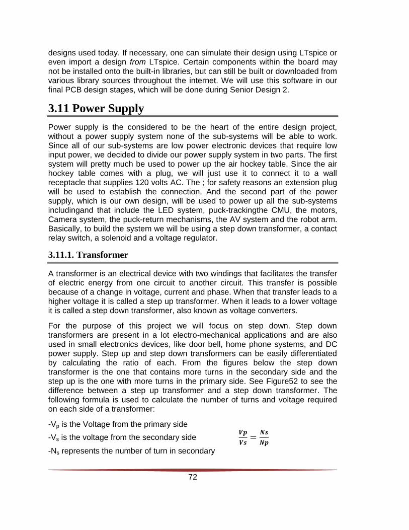
72
designs used today. If necessary, one can simulate their design using LTspice or even import a design from LTspice. Certain components within the board may not be installed onto the built-in libraries, but can still be built or downloaded from various library sources throughout the internet. We will use this software in our final PCB design stages, which will be done during Senior Design 2.
3.11 Power Supply
Power supply is the considered to be the heart of the entire design project, without a power supply system none of the sub-systems will be able to work. Since all of our sub-systems are low power electronic devices that require low input power, we decided to divide our power supply system in two parts. The first system will pretty much be used to power up the air hockey table. Since the air hockey table comes with a plug, we will just use it to connect it to a wall receptacle that supplies 120 volts AC. The ; for safety reasons an extension plug will be used to establish the connection. And the second part of the power supply, which is our own design, will be used to power up all the sub-systems includingand that include the LED system, puck-trackingthe CMU, the motors, Camera system, the puck-return mechanisms, the AV system and the robot arm. Basically, to build the system we will be using a step down transformer, a contact relay switch, a solenoid and a voltage regulator.
3.11.1. Transformer
A transformer is an electrical device with two windings that facilitates the transfer of electric energy from one circuit to another circuit. This transfer is possible because of a change in voltage, current and phase. When that transfer leads to a higher voltage it is called a step up transformer. When it leads to a lower voltage it is called a step down transformer, also known as voltage converters.
For the purpose of this project we will focus on step down. Step down transformers are present in a lot electro-mechanical applications and are also used in small electronics devices, like door bell, home phone systems, and DC power supply. Step up and step down transformers can be easily differentiated by calculating the ratio of each. From the figures below the step down transformer is the one that contains more turns in the secondary side and the step up is the one with more turns in the primary side. See Figure52 to see the difference between a step up transformer and a step down transformer. The following formula is used to calculate the number of turns and voltage required on each side of a transformer:
-Vp is the Voltage from the primary side
-Vs is the voltage from the secondary side
-Ns represents the number of turn in secondary
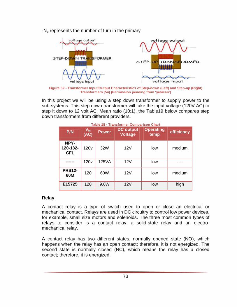
73
-Np represents the number of turn in the primary
Figure 52 - Transformer Input/Output Characteristics of Step-down (Left) and Step-up (Right)
Transformers [54] (Permission pending from ‘yesican’)
In this project we will be using a step down transformer to supply power to the sub-systems. This step down transformer will take the input voltage (120V AC) to step it down to 12 volt AC. Mean ratio (10:1), the Table19 below compares step down transformers from different providers.
Table 18 - Transformer Comparison Chart
P/N Vin
(AC) Power
DC output Voltage
Operating temp
efficiency
NPY-120-132-
CFL 120v 32W 12V low medium
------ 120v 125VA 12V low ----
PRS12-60M
120 60W 12V low medium
E15725 120 9.6W 12V low high
Relay
A contact relay is a type of switch used to open or close an electrical or mechanical contact. Relays are used in DC circuitry to control low power devices, for example, small size motors and solenoids. The three most common types of relays to consider is a contact relay, a solid-state relay and an electro-mechanical relay. A contact relay has two different states, normally opened state (NO), which happens when the relay has an open contact; therefore, it is not energized. The second state is normally closed (NC), which means the relay has a closed contact; therefore, it is energized.
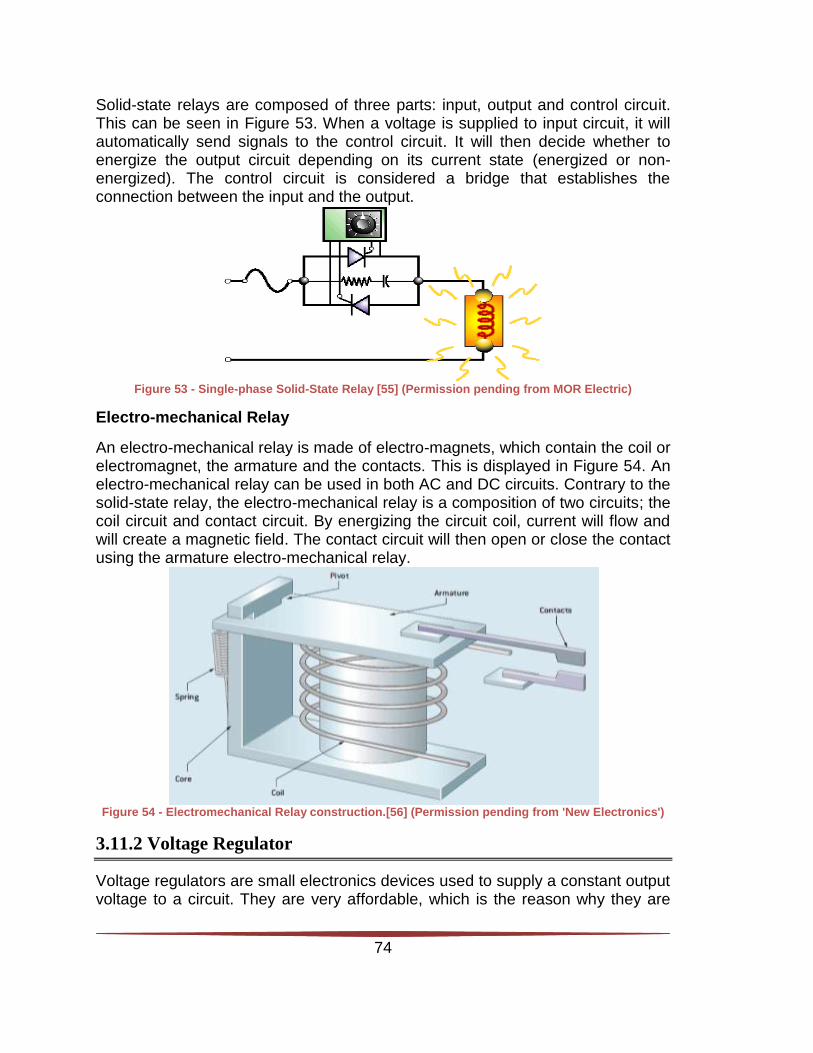
74
Solid-state relays are composed of three parts: input, output and control circuit. This can be seen in Figure 53. When a voltage is supplied to input circuit, it will automatically send signals to the control circuit. It will then decide whether to energize the output circuit depending on its current state (energized or non-energized). The control circuit is considered a bridge that establishes the connection between the input and the output.
Figure 53 - Single-phase Solid-State Relay [55] (Permission pending from MOR Electric)
Electro-mechanical Relay
An electro-mechanical relay is made of electro-magnets, which contain the coil or electromagnet, the armature and the contacts. This is displayed in Figure 54. An electro-mechanical relay can be used in both AC and DC circuits. Contrary to the solid-state relay, the electro-mechanical relay is a composition of two circuits; the coil circuit and contact circuit. By energizing the circuit coil, current will flow and will create a magnetic field. The contact circuit will then open or close the contact using the armature electro-mechanical relay.
Figure 54 - Electromechanical Relay construction.[56] (Permission pending from 'New Electronics')
3.11.2 Voltage Regulator
Voltage regulators are small electronics devices used to supply a constant output voltage to a circuit. They are very affordable, which is the reason why they are
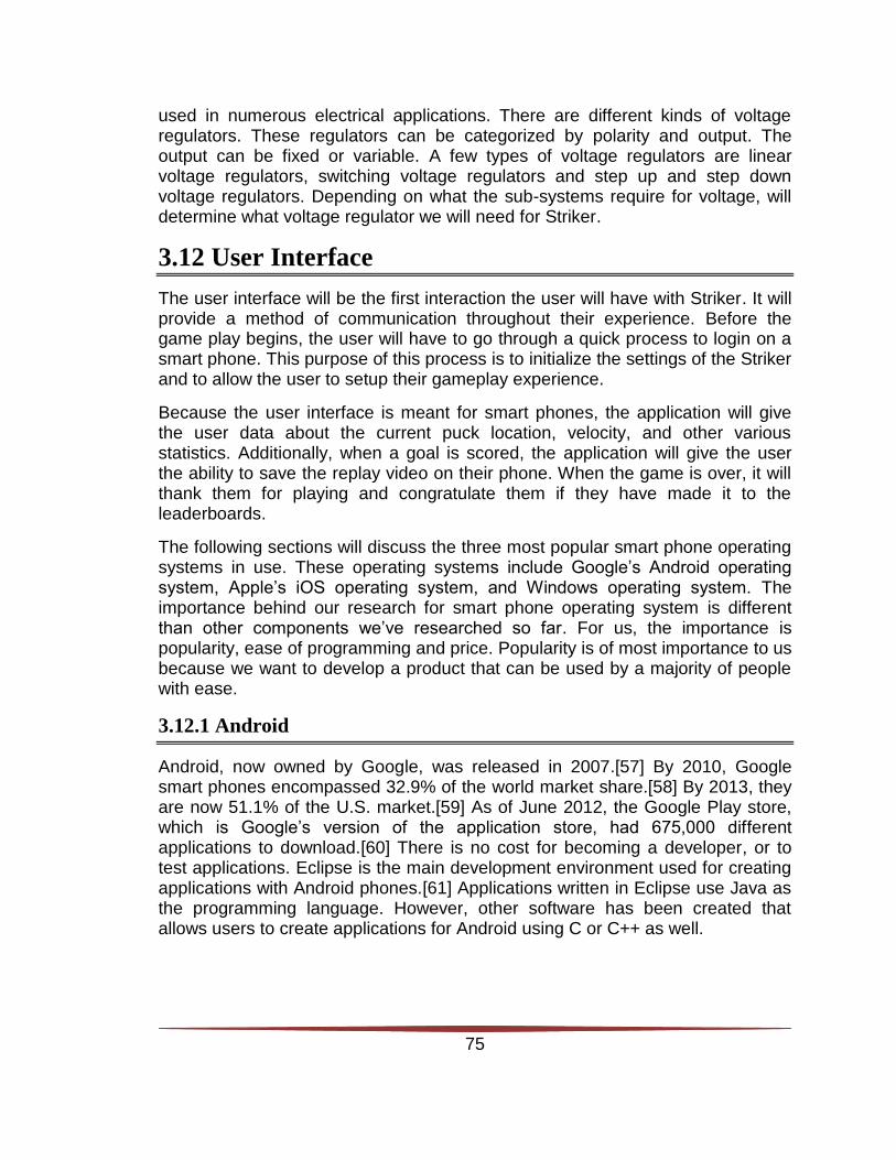
75
used in numerous electrical applications. There are different kinds of voltage regulators. These regulators can be categorized by polarity and output. The output can be fixed or variable. A few types of voltage regulators are linear voltage regulators, switching voltage regulators and step up and step down voltage regulators. Depending on what the sub-systems require for voltage, will determine what voltage regulator we will need for Striker.
3.12 User Interface
The user interface will be the first interaction the user will have with Striker. It will provide a method of communication throughout their experience. Before the game play begins, the user will have to go through a quick process to login on a smart phone. This purpose of this process is to initialize the settings of the Striker and to allow the user to setup their gameplay experience.
Because the user interface is meant for smart phones, the application will give the user data about the current puck location, velocity, and other various statistics. Additionally, when a goal is scored, the application will give the user the ability to save the replay video on their phone. When the game is over, it will thank them for playing and congratulate them if they have made it to the leaderboards.
The following sections will discuss the three most popular smart phone operating systems in use. These operating systems include Google’s Android operating system, Apple’s iOS operating system, and Windows operating system. The importance behind our research for smart phone operating system is different than other components we’ve researched so far. For us, the importance is popularity, ease of programming and price. Popularity is of most importance to us because we want to develop a product that can be used by a majority of people with ease.
3.12.1 Android
Android, now owned by Google, was released in 2007.[57] By 2010, Google smart phones encompassed 32.9% of the world market share.[58] By 2013, they are now 51.1% of the U.S. market.[59] As of June 2012, the Google Play store, which is Google’s version of the application store, had 675,000 different applications to download.[60] There is no cost for becoming a developer, or to test applications. Eclipse is the main development environment used for creating applications with Android phones.[61] Applications written in Eclipse use Java as the programming language. However, other software has been created that allows users to create applications for Android using C or C++ as well.
76
3.12.2 iOS
iOS was created by Apple to run on their smart phones. iOS was first released in 2007.[62] By 2010, Apple smart phones encompassed 16% of the world wide smart phone market.[57] By 2013, iOS encompassed 43.4% of the U.S. smart phone market.[58] As of June 2013, the application store had 900,000 different applications available to download.[61] The cost for becoming a developer and testing applications is $99 per year.[62] Xcode is the main development environment used for creating applications with iOS phones.[63] Applications written in Xcode use objective-c as the programming language. Other software has been created that allows users to create applications for iOS using C or C++ as well.
3.12.3 Windows Phone
Windows Phone was created by Microsoft to run on their smart phones. Microsoft Phone operating system was first released in 2010.[64] By 2010 Microsoft’s smart phones encompassed 3.1% of the world smart phone market.[65] By 2013, Windows Phone encompassed 3.5% of the smart phone market.[58] Although Windows Phone is a much smaller portion of the market, with respect to Android and IOS, it is fastest growing smart phone operating system.[65]The cost for becoming a developer and testing applications is $19 per year.[62] The Windows Phone Software Development Kit is the main development environment used for creating applications for Windows Phone.[66] Applications for Windows Phone can be written in C#, Visual Basic, or C++.[67]
3.12.4 Receiving Data From Striker
As mentioned in section 3.9, data being relayed from the microcontroller on Striker is being transmitted wirelessly. Most smart phones have the capacity of turning on and off Bluetooth communication as well as Wi-Fi. When the application initializes, a requirement of the application is that the communication method chosen become activated. Therefore, the first function that the application performs is to enable the device to use that wireless communication standard. This action enables the smart phone and the Striker to be able to communicate with each other.
77
4 Design Summary of Hardware and Software
4.1 System Overview
The Striker system is composed of many subsystems. After much research, the main processors chosen are the Arduino Uno for overall system; the Arduino Mini Pro for the robotic arm, Pixy for the tracking system, and Davinci for AV.
The Arduino Uno was chosen for the main system for many reasons. It consists of the right amount of I/O pins needed for Striker. The Arduino Uno, is a very popular microcontroller by electronic hobbyist, therefore we have found that many devices are built to interface with the Arduino, such as the Red Bear BLE shield and Pixy. Additionally, there is a lot of support for writing software for the Arduino. Arduino provides a large number of libraries and built in functions that are specific to the type of coding considerations we will have for Striker.
The Arduino Uno also has the advantages of being able to communicate through several communication standards of interest, specifically SPI and UART. It also has a fast clock speed at 16 MHz with low power consumption. Additionally, programming an Arduino uses a language that is very similar to C. The processors chosen for all of the subsystem will be further discussed in the following sections.
Figure 55 demonstrates how the processors are connected to each other and to other components of Striker. This figure also shows what pin numbers correspond to which connections. The pin assignments are important because not every pin has the same capabilities in the processors. For example, only pins 3, 5, 6, 9, 10, and 11 are capable of PWM on the Arduino Uno. Therefore, devices such as motors that rely on PWM, can only be connected to those pins.
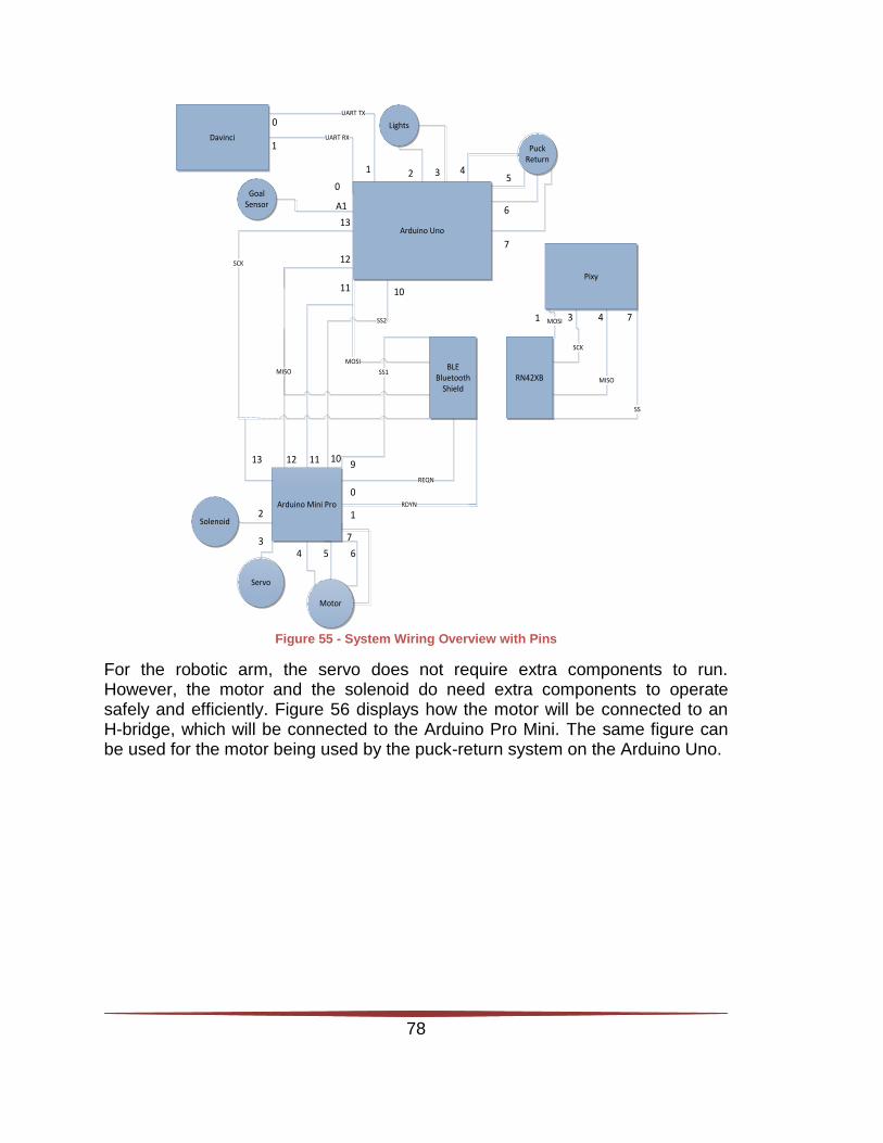
78
Arduino Uno
BLE Bluetooth
Shield
SS1
MOSI
MISO
SCK
1 2
3
4
5 6
7
0
11
12
13
Arduino Mini Pro
SS2
10111213
Motor
Solenoid
Servo
Pixy
RN42XB
MOSI
SCK
MISO
SS
1 3
Davinci UART RX
UART TX
Lights
Goal Sensor
Puck Return
3 4
10
REQN
RDYN
9
0
1
4
2
0
1
A1
5
6
7
7
Figure 55 - System Wiring Overview with Pins
For the robotic arm, the servo does not require extra components to run. However, the motor and the solenoid do need extra components to operate safely and efficiently. Figure 56 displays how the motor will be connected to an H-bridge, which will be connected to the Arduino Pro Mini. The same figure can be used for the motor being used by the puck-return system on the Arduino Uno.
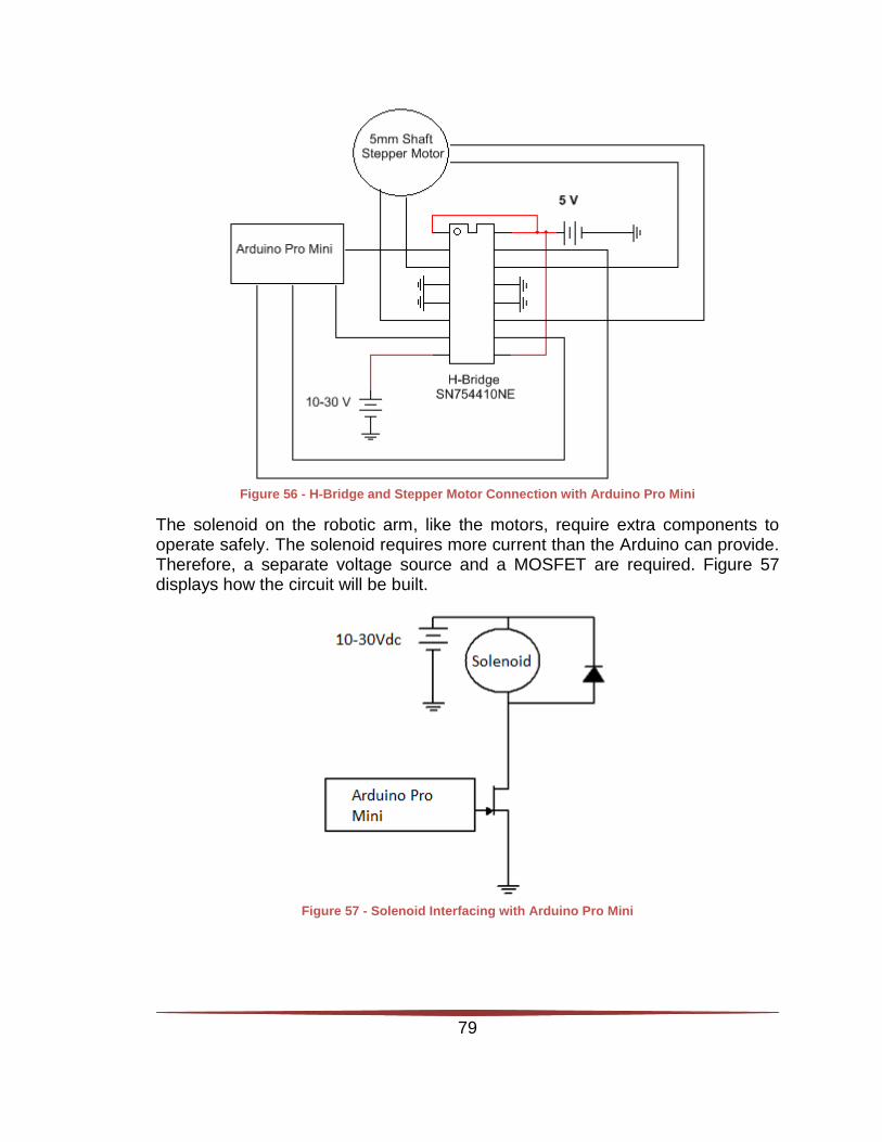
79
Figure 56 - H-Bridge and Stepper Motor Connection with Arduino Pro Mini
The solenoid on the robotic arm, like the motors, require extra components to operate safely. The solenoid requires more current than the Arduino can provide. Therefore, a separate voltage source and a MOSFET are required. Figure 57 displays how the circuit will be built.
Figure 57 - Solenoid Interfacing with Arduino Pro Mini
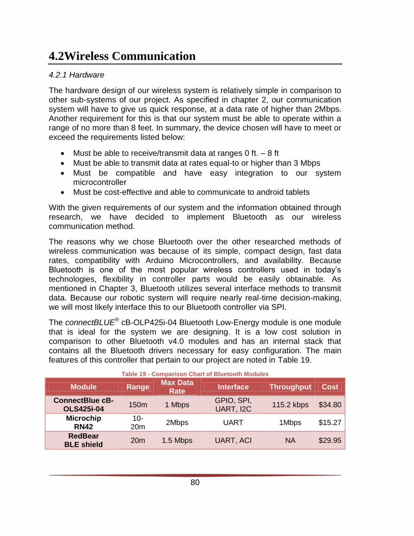
80
4.2Wireless Communication
4.2.1 Hardware
The hardware design of our wireless system is relatively simple in comparison to other sub-systems of our project. As specified in chapter 2, our communication system will have to give us quick response, at a data rate of higher than 2Mbps. Another requirement for this is that our system must be able to operate within a range of no more than 8 feet. In summary, the device chosen will have to meet or exceed the requirements listed below:
Must be able to receive/transmit data at ranges 0 ft. – 8 ft
Must be able to transmit data at rates equal-to or higher than 3 Mbps
Must be compatible and have easy integration to our system microcontroller
Must be cost-effective and able to communicate to android tablets
With the given requirements of our system and the information obtained through research, we have decided to implement Bluetooth as our wireless communication method.
The reasons why we chose Bluetooth over the other researched methods of wireless communication was because of its simple, compact design, fast data rates, compatibility with Arduino Microcontrollers, and availability. Because Bluetooth is one of the most popular wireless controllers used in today’s technologies, flexibility in controller parts would be easily obtainable. As mentioned in Chapter 3, Bluetooth utilizes several interface methods to transmit data. Because our robotic system will require nearly real-time decision-making, we will most likely interface this to our Bluetooth controller via SPI.
The connectBLUE® cB-OLP425i-04 Bluetooth Low-Energy module is one module that is ideal for the system we are designing. It is a low cost solution in comparison to other Bluetooth v4.0 modules and has an internal stack that contains all the Bluetooth drivers necessary for easy configuration. The main features of this controller that pertain to our project are noted in Table 19.
Table 19 - Comparison Chart of Bluetooth Modules
Module Range Max Data
Rate Interface Throughput Cost
ConnectBlue cB-OLS425i-04
150m 1 Mbps GPIO, SPI, UART, I2C
115.2 kbps $34.80
Microchip RN42
10-20m
2Mbps UART 1Mbps $15.27
RedBear BLE shield
20m 1.5 Mbps UART, ACI NA $29.95
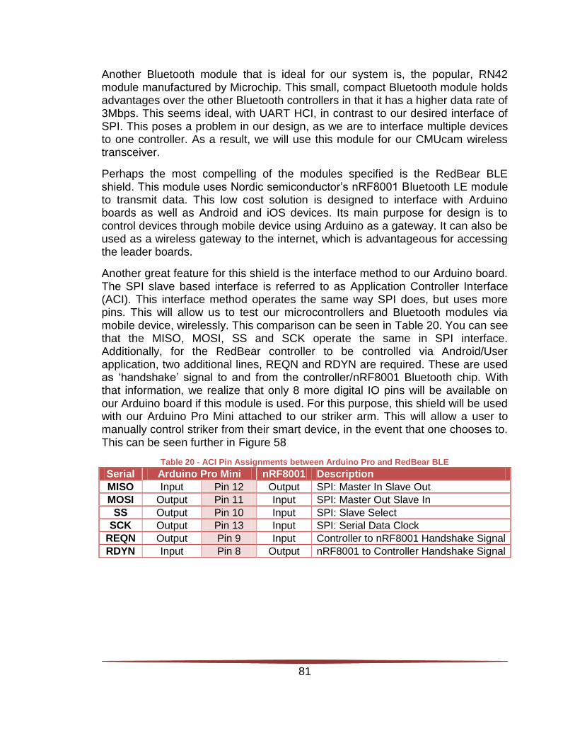
81
Another Bluetooth module that is ideal for our system is, the popular, RN42 module manufactured by Microchip. This small, compact Bluetooth module holds advantages over the other Bluetooth controllers in that it has a higher data rate of 3Mbps. This seems ideal, with UART HCI, in contrast to our desired interface of SPI. This poses a problem in our design, as we are to interface multiple devices to one controller. As a result, we will use this module for our CMUcam wireless transceiver.
Perhaps the most compelling of the modules specified is the RedBear BLE shield. This module uses Nordic semiconductor’s nRF8001 Bluetooth LE module to transmit data. This low cost solution is designed to interface with Arduino boards as well as Android and iOS devices. Its main purpose for design is to control devices through mobile device using Arduino as a gateway. It can also be used as a wireless gateway to the internet, which is advantageous for accessing the leader boards.
Another great feature for this shield is the interface method to our Arduino board. The SPI slave based interface is referred to as Application Controller Interface (ACI). This interface method operates the same way SPI does, but uses more pins. This will allow us to test our microcontrollers and Bluetooth modules via mobile device, wirelessly. This comparison can be seen in Table 20. You can see that the MISO, MOSI, SS and SCK operate the same in SPI interface. Additionally, for the RedBear controller to be controlled via Android/User application, two additional lines, REQN and RDYN are required. These are used as ‘handshake’ signal to and from the controller/nRF8001 Bluetooth chip. With that information, we realize that only 8 more digital IO pins will be available on our Arduino board if this module is used. For this purpose, this shield will be used with our Arduino Pro Mini attached to our striker arm. This will allow a user to manually control striker from their smart device, in the event that one chooses to. This can be seen further in Figure 58
Table 20 - ACI Pin Assignments between Arduino Pro and RedBear BLE
Serial Arduino Pro Mini nRF8001 Description
MISO Input Pin 12 Output SPI: Master In Slave Out
MOSI Output Pin 11 Input SPI: Master Out Slave In
SS Output Pin 10 Input SPI: Slave Select
SCK Output Pin 13 Input SPI: Serial Data Clock
REQN Output Pin 9 Input Controller to nRF8001 Handshake Signal
RDYN Input Pin 8 Output nRF8001 to Controller Handshake Signal
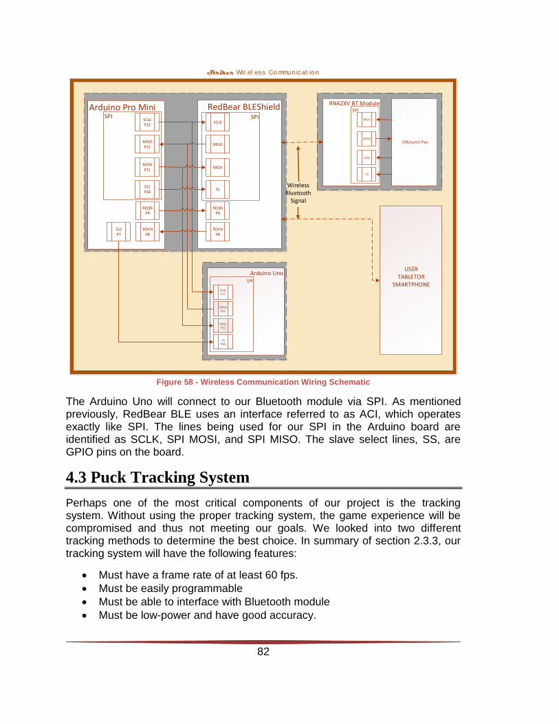
82
Striker Wir el ess Co mmun icat ion
Arduino Pro Mini RedBear BLEShieldSPI
SCLK
MISO
MOSI
SS
SPI
MOSIP11
MISOP12
SCLKP13
SS1P10
Arduino UnoSPI
MOSIP11
MISOP12
SCLKP13
SSP10
SS2P7
USER TABLETOR
SMARTPHONE
CMUcam5 Pixy
RN42XV BT ModuleSPI
MOSI
MISO
SCLK
SS
REQNP9
RDYNP8
REQNP9
RDYNP8
WirelessBluetooth
Signal
Figure 58 - Wireless Communication Wiring Schematic
The Arduino Uno will connect to our Bluetooth module via SPI. As mentioned previously, RedBear BLE uses an interface referred to as ACI, which operates exactly like SPI. The lines being used for our SPI in the Arduino board are identified as SCLK, SPI MOSI, and SPI MISO. The slave select lines, SS, are GPIO pins on the board.
4.3 Puck Tracking System
Perhaps one of the most critical components of our project is the tracking system. Without using the proper tracking system, the game experience will be compromised and thus not meeting our goals. We looked into two different tracking methods to determine the best choice. In summary of section 2.3.3, our tracking system will have the following features:
Must have a frame rate of at least 60 fps.
Must be easily programmable
Must be able to interface with Bluetooth module
Must be low-power and have good accuracy.
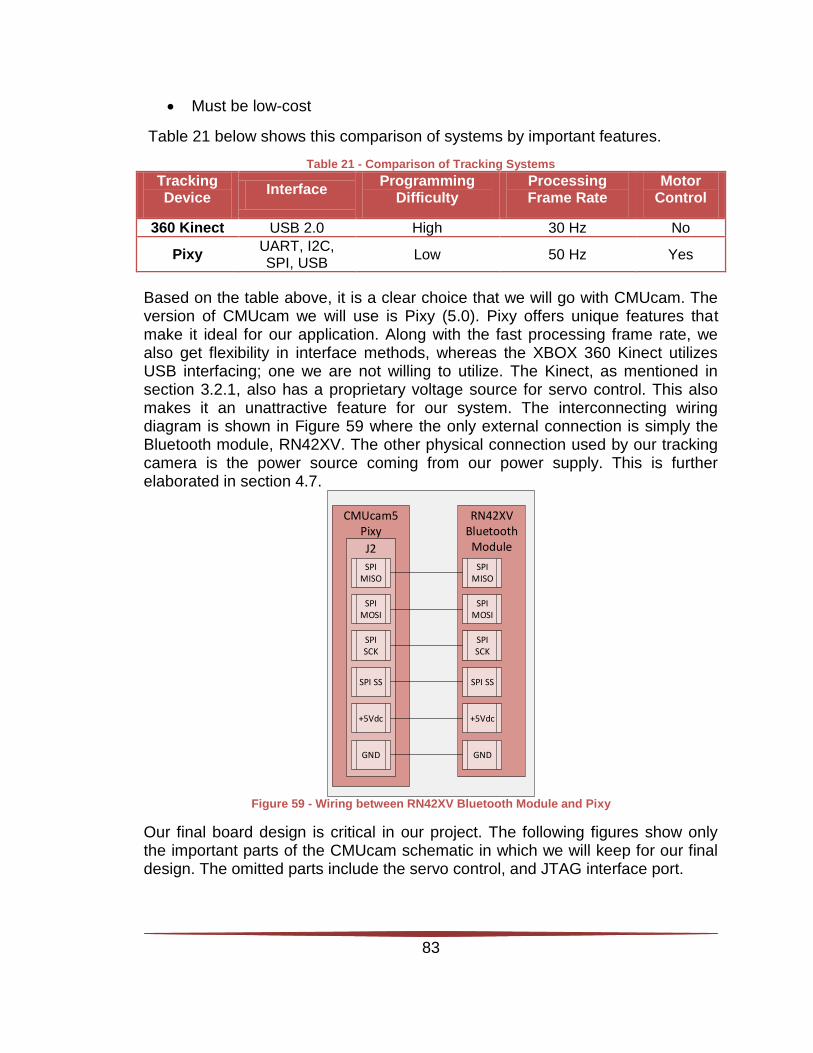
83
Must be low-cost
Table 21 below shows this comparison of systems by important features.
Table 21 - Comparison of Tracking Systems
Tracking Device
Interface Programming
Difficulty Processing Frame Rate
Motor Control
360 Kinect USB 2.0 High 30 Hz No
Pixy UART, I2C, SPI, USB
Low 50 Hz Yes
Based on the table above, it is a clear choice that we will go with CMUcam. The version of CMUcam we will use is Pixy (5.0). Pixy offers unique features that make it ideal for our application. Along with the fast processing frame rate, we also get flexibility in interface methods, whereas the XBOX 360 Kinect utilizes USB interfacing; one we are not willing to utilize. The Kinect, as mentioned in section 3.2.1, also has a proprietary voltage source for servo control. This also makes it an unattractive feature for our system. The interconnecting wiring diagram is shown in Figure 59 where the only external connection is simply the Bluetooth module, RN42XV. The other physical connection used by our tracking camera is the power source coming from our power supply. This is further elaborated in section 4.7.
CMUcam5 Pixy
J2
SPIMISO
SPI MOSI
SPI SCK
SPI SS
+5Vdc
GND
RN42XVBluetooth Module
SPIMISO
SPI MOSI
SPI SCK
SPI SS
+5Vdc
GND
Figure 59 - Wiring between RN42XV Bluetooth Module and Pixy
Our final board design is critical in our project. The following figures show only the important parts of the CMUcam schematic in which we will keep for our final design. The omitted parts include the servo control, and JTAG interface port.
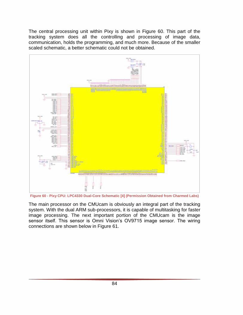
84
The central processing unit within Pixy is shown in Figure 60. This part of the tracking system does all the controlling and processing of image data, communication, holds the programming, and much more. Because of the smaller scaled schematic, a better schematic could not be obtained.
Figure 60 - Pixy CPU: LPC4330 Dual-Core Schematic [4] (Permission Obtained from Charmed Labs)
The main processor on the CMUcam is obviously an integral part of the tracking system. With the dual ARM sub-processors, it is capable of multitasking for faster image processing. The next important portion of the CMUcam is the image sensor itself. This sensor is Omni Vision’s OV9715 image sensor. The wiring connections are shown below in Figure 61.
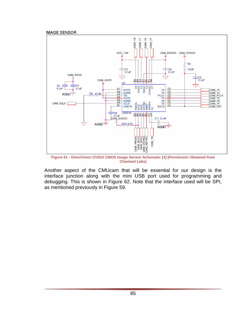
85
Figure 61 - OmniVision OV915 CMOS Image Sensor Schematic [4] (Permission Obtained from
Charmed Labs)
Another aspect of the CMUcam that will be essential for our design is the interface junction along with the mini USB port used for programming and debugging. This is shown in Figure 62. Note that the interface used will be SPI, as mentioned previously in Figure 59.
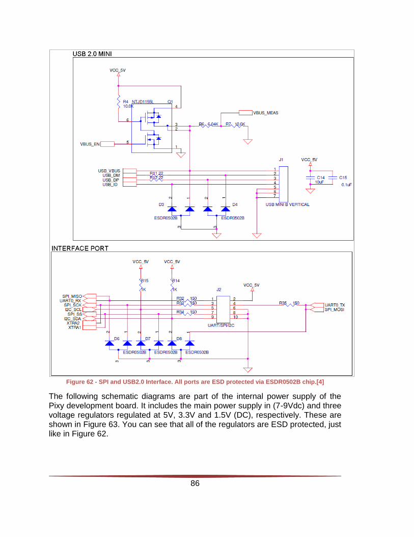
86
Figure 62 - SPI and USB2.0 Interface. All ports are ESD protected via ESDR0502B chip.[4]
The following schematic diagrams are part of the internal power supply of the Pixy development board. It includes the main power supply in (7-9Vdc) and three voltage regulators regulated at 5V, 3.3V and 1.5V (DC), respectively. These are shown in Figure 63. You can see that all of the regulators are ESD protected, just like in Figure 62.
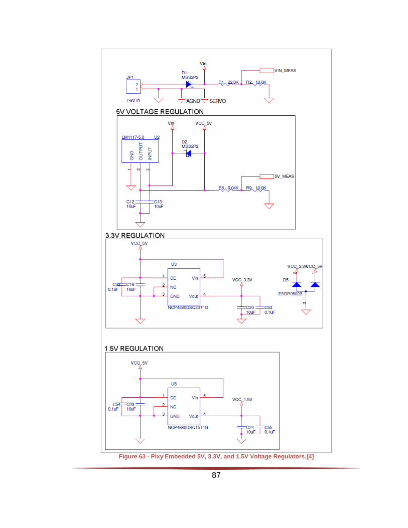
87
Figure 63 - Pixy Embedded 5V, 3.3V, and 1.5V Voltage Regulators.[4]
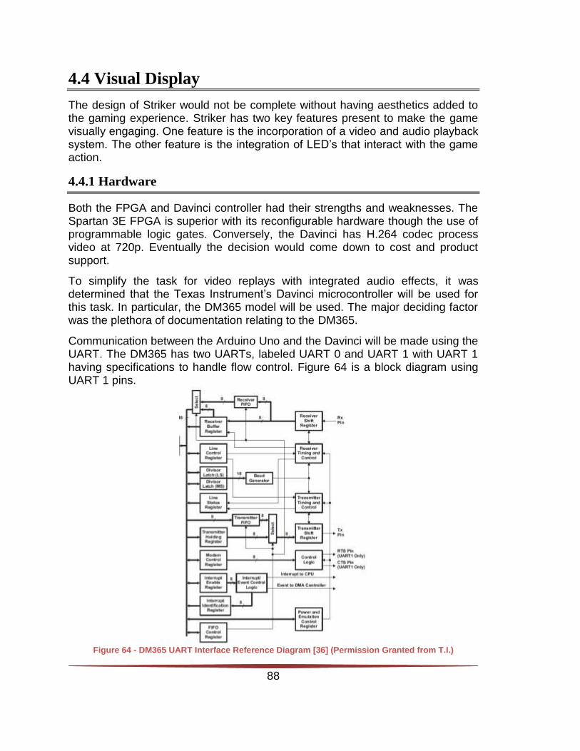
88
4.4 Visual Display
The design of Striker would not be complete without having aesthetics added to the gaming experience. Striker has two key features present to make the game visually engaging. One feature is the incorporation of a video and audio playback system. The other feature is the integration of LED’s that interact with the game action.
4.4.1 Hardware
Both the FPGA and Davinci controller had their strengths and weaknesses. The Spartan 3E FPGA is superior with its reconfigurable hardware though the use of programmable logic gates. Conversely, the Davinci has H.264 codec process video at 720p. Eventually the decision would come down to cost and product support.
To simplify the task for video replays with integrated audio effects, it was determined that the Texas Instrument’s Davinci microcontroller will be used for this task. In particular, the DM365 model will be used. The major deciding factor was the plethora of documentation relating to the DM365.
Communication between the Arduino Uno and the Davinci will be made using the UART. The DM365 has two UARTs, labeled UART 0 and UART 1 with UART 1 having specifications to handle flow control. Figure 64 is a block diagram using UART 1 pins.
Figure 64 - DM365 UART Interface Reference Diagram [36] (Permission Granted from T.I.)
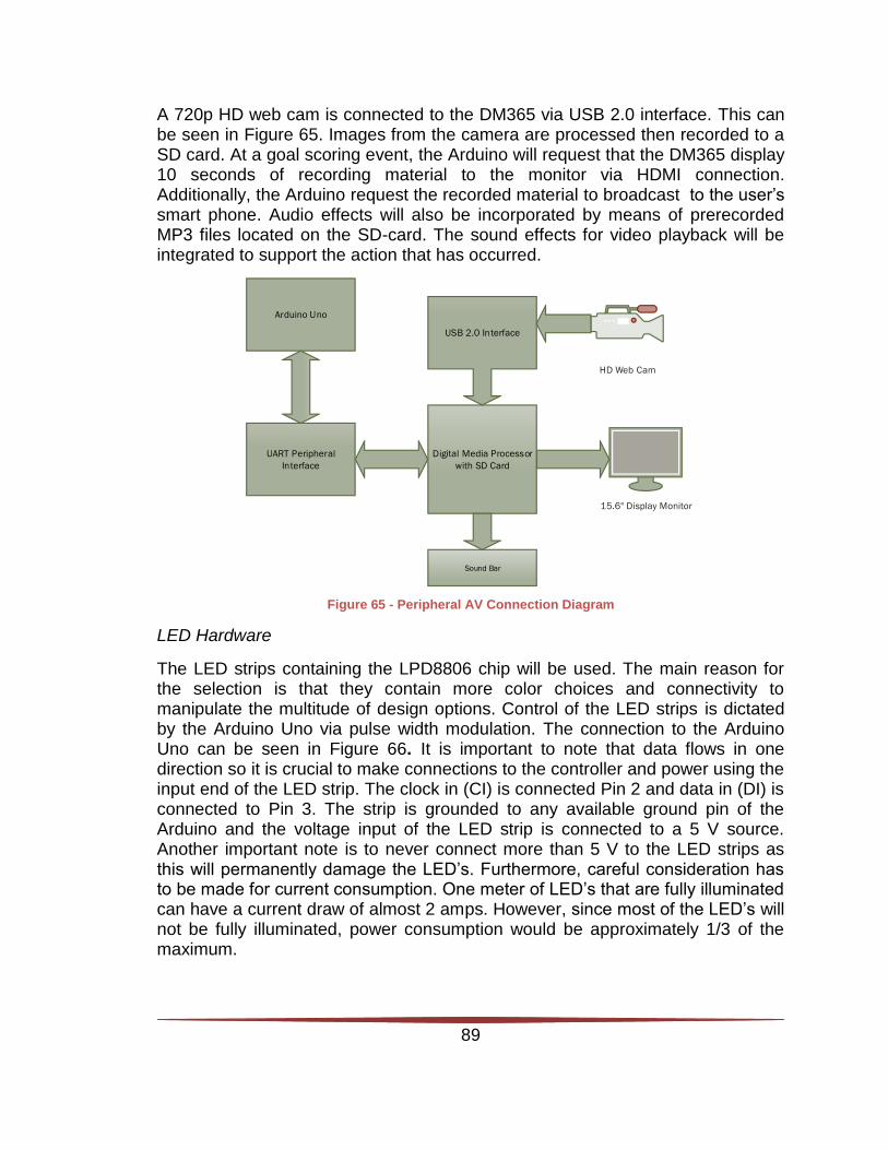
89
A 720p HD web cam is connected to the DM365 via USB 2.0 interface. This can be seen in Figure 65. Images from the camera are processed then recorded to a SD card. At a goal scoring event, the Arduino will request that the DM365 display 10 seconds of recording material to the monitor via HDMI connection. Additionally, the Arduino request the recorded material to broadcast to the user’s smart phone. Audio effects will also be incorporated by means of prerecorded MP3 files located on the SD-card. The sound effects for video playback will be integrated to support the action that has occurred.
Arduino Uno
UART Peripheral
Interface
Digital Media Processor
with SD Card
15.6" Display Monitor
HD Web Cam
USB 2.0 Interface
Sound Bar
Figure 65 - Peripheral AV Connection Diagram
LED Hardware
The LED strips containing the LPD8806 chip will be used. The main reason for the selection is that they contain more color choices and connectivity to manipulate the multitude of design options. Control of the LED strips is dictated by the Arduino Uno via pulse width modulation. The connection to the Arduino Uno can be seen in Figure 66. It is important to note that data flows in one direction so it is crucial to make connections to the controller and power using the input end of the LED strip. The clock in (CI) is connected Pin 2 and data in (DI) is connected to Pin 3. The strip is grounded to any available ground pin of the Arduino and the voltage input of the LED strip is connected to a 5 V source. Another important note is to never connect more than 5 V to the LED strips as this will permanently damage the LED’s. Furthermore, careful consideration has to be made for current consumption. One meter of LED’s that are fully illuminated can have a current draw of almost 2 amps. However, since most of the LED’s will not be fully illuminated, power consumption would be approximately 1/3 of the maximum.
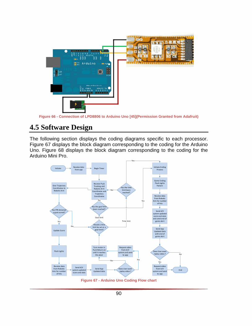
90
Figure 66 - Connection of LPD8806 to Arduino Uno [45](Permission Granted from Adafruit)
4.5 Software Design
The following section displays the coding diagrams specific to each processor. Figure 67 displays the block diagram corresponding to the coding for the Arduino Uno. Figure 68 displays the block diagram corresponding to the coding for the Arduino Mini Pro.
Initiate
Receive Puck Tracking and Robotic Arm
Coordinates and Trajectory
Coordinates
Give Trajectory Coordinates to
Robotic Arm
Has PIR detected a goal scored?
Flash Lights
Turn motor in Puck Return on until it reaches
the plaer
Send A/V system updated score and stats
Begin TimerReceive data
from app
Should a time limit be set or a
goal limit?
Has the goal limit been reached?
No
Has the time limit been reached?
No
No
Yes
Yes
Time limit
Goal limit
Update Score
Yes
Does User want replay video ?
Send App Updated data
Request video from A/V
system and send to app
No Yes
Receive data from Robotic
Arm for number of hits
Game Ending Flash Lights
Pattern
Send A/V system updated score and stats and send end of
game alert
Does User want replay video ?
Send App Updated data
with end of game alert
Receive data from Robotic
Arm for number of hits
Initiate Ending Process
Request video from A/V
system and send to app
End
Yes
No
Figure 67 - Arduino Uno Coding Flow chart
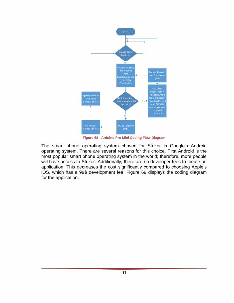
91
Start
Receive Tracking and Robotic
Arm Coordinates and
Trajectory Coordinates
Calculate distance from Robotic Arm is from trajectory coordinates and
send PWM to motor to move
required distance
Is Robotic Arm close enough to hit
the puck?
No
Rotate Servo to aim for players
goal
Make solenoid strike
Yes
Increment number of hits
Update Arduino Uno with
number of hits
Is puck being tracked?
Yes
No
Figure 68 - Arduino Pro Mini Coding Flow Diagram
The smart phone operating system chosen for Striker is Google’s Android operating system. There are several reasons for this choice. First Android is the most popular smart phone operating system in the world; therefore, more people will have access to Striker. Additionally, there are no developer fees to create an application. This decreases the cost significantly compared to choosing Apple’s iOS, which has a 99$ development fee. Figure 69 displays the coding diagram for the application.
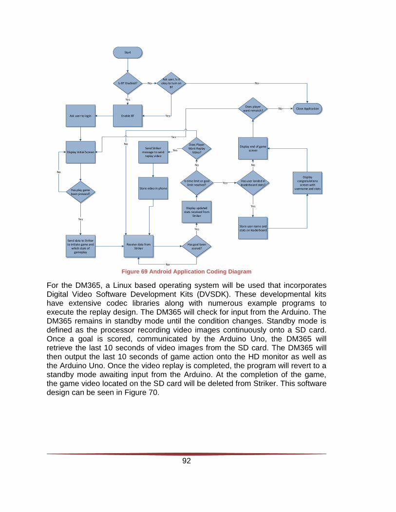
92
Start
Is BT Enabled?Ask user, Is it
okay to turn on BT
Enable BTAsk user to login
Display Initial Screen
Has play game been pressed?
Send data to Striker to initiate game and
which style of gameplay
Receive data from Striker
Has goal been scored?
Display updated stats received from
Striker
Yes
No
Yes
No
Yes
No
Yes
Does Player Want Replay
Video?
Is time limit or goal limit reached?
Has user landed in leaderboard stats?
Yes
No
No
Send Striker message to send
replay video
Yes
Store video in phone
Store user name and stats on leaderboard
Yes
Display congratulations
screen with username and stats
Display end of game screen
No
Does player want rematch?
Yes
Close ApplicationNo
No
Figure 69 Android Application Coding Diagram
For the DM365, a Linux based operating system will be used that incorporates Digital Video Software Development Kits (DVSDK). These developmental kits have extensive codec libraries along with numerous example programs to execute the replay design. The DM365 will check for input from the Arduino. The DM365 remains in standby mode until the condition changes. Standby mode is defined as the processor recording video images continuously onto a SD card. Once a goal is scored, communicated by the Arduino Uno, the DM365 will retrieve the last 10 seconds of video images from the SD card. The DM365 will then output the last 10 seconds of game action onto the HD monitor as well as the Arduino Uno. Once the video replay is completed, the program will revert to a standby mode awaiting input from the Arduino. At the completion of the game, the game video located on the SD card will be deleted from Striker. This software design can be seen in Figure 70.
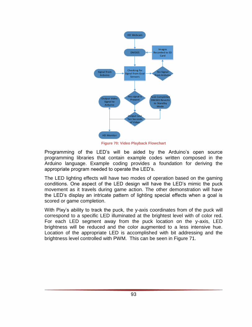
93
DM365
Checking for Signal from Goal
Sensors
Yes signal is Present
Signal from Arduino
HD Monitor
No Signal from Arduino
Images Recorded to SD
Card
HD Webcam
Output Video Signal to Arduino
Output Last Ten Seconds
of Video
Task CompletedDM365 Reverts
to Standby Mode
Figure 70: Video Playback Flowchart
Programming of the LED’s will be aided by the Arduino’s open source programming libraries that contain example codes written composed in the Arduino language. Example coding provides a foundation for deriving the appropriate program needed to operate the LED’s.
The LED lighting effects will have two modes of operation based on the gaming conditions. One aspect of the LED design will have the LED’s mimic the puck movement as it travels during game action. The other demonstration will have the LED’s display an intricate pattern of lighting special effects when a goal is scored or game completion.
With Pixy’s ability to track the puck, the y-axis coordinates from of the puck will correspond to a specific LED illuminated at the brightest level with of color red. For each LED segment away from the puck location on the y-axis, LED brightness will be reduced and the color augmented to a less intensive hue. Location of the appropriate LED is accomplished with bit addressing and the brightness level controlled with PWM. This can be seen in Figure 71.
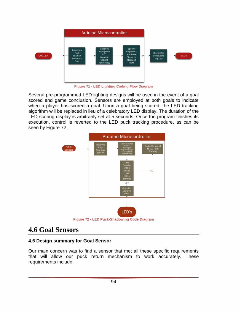
94
CMU Cam LED s
Interprets
Puck
Position
from CMU
Cam
Illuminates
Correspond
ing LED
Identifies
Appropriate
LED
Location
with Bit
Addressing
Specific
Brightness
and Color
Choice by
Means of
PWM
Figure 71 - LED Lighting Coding Flow Diagram
Several pre-programmed LED lighting designs will be used in the event of a goal scored and game conclusion. Sensors are employed at both goals to indicate when a player has scored a goal. Upon a goal being scored, the LED tracking algorithm will be replaced in lieu of a celebratory LED display. The duration of the LED scoring display is arbitrarily set at 5 seconds. Once the program finishes its execution, control is reverted to the LED puck tracking procedure, as can be seen by Figure 72.
Receives
Input
from Goal
Sensors
Control Switched
from LED
Tracking to
Programmed LED
Special Effects
Demonstration
LED s
Output to
LED s via
PWM
Control Returned
to LED Puck
Tracking
Time
Duration
of LED
Display
Less
Than 5
Seconds
YES
NO
Goal
Sensors
Figure 72 - LED Puck-Shadowing Code Diagram
4.6 Goal Sensors
4.6 Design summary for Goal Sensor
Our main concern was to find a sensor that met all these specific requirements that will allow our puck return mechanism to work accurately. These requirements include:
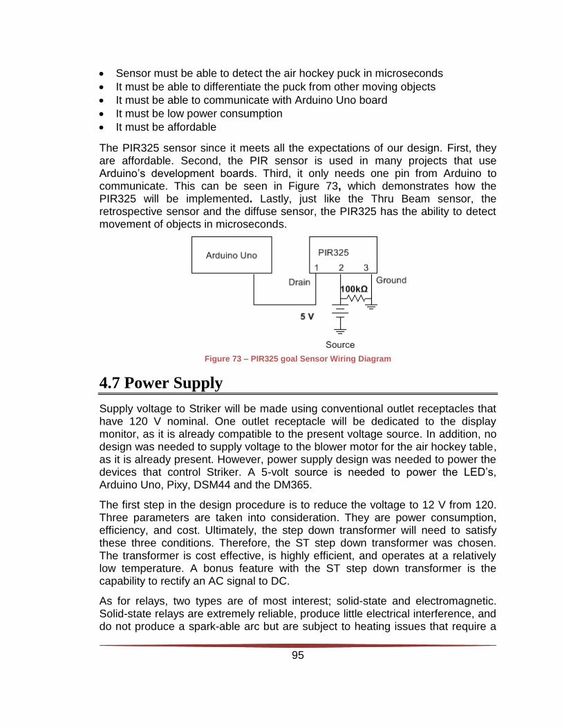
95
Sensor must be able to detect the air hockey puck in microseconds
It must be able to differentiate the puck from other moving objects
It must be able to communicate with Arduino Uno board
It must be low power consumption
It must be affordable
The PIR325 sensor since it meets all the expectations of our design. First, they are affordable. Second, the PIR sensor is used in many projects that use Arduino’s development boards. Third, it only needs one pin from Arduino to communicate. This can be seen in Figure 73, which demonstrates how the PIR325 will be implemented. Lastly, just like the Thru Beam sensor, the retrospective sensor and the diffuse sensor, the PIR325 has the ability to detect movement of objects in microseconds.
Figure 73 – PIR325 goal Sensor Wiring Diagram
4.7 Power Supply
Supply voltage to Striker will be made using conventional outlet receptacles that have 120 V nominal. One outlet receptacle will be dedicated to the display monitor, as it is already compatible to the present voltage source. In addition, no design was needed to supply voltage to the blower motor for the air hockey table, as it is already present. However, power supply design was needed to power the devices that control Striker. A 5-volt source is needed to power the LED’s, Arduino Uno, Pixy, DSM44 and the DM365.
The first step in the design procedure is to reduce the voltage to 12 V from 120. Three parameters are taken into consideration. They are power consumption, efficiency, and cost. Ultimately, the step down transformer will need to satisfy these three conditions. Therefore, the ST step down transformer was chosen. The transformer is cost effective, is highly efficient, and operates at a relatively low temperature. A bonus feature with the ST step down transformer is the capability to rectify an AC signal to DC.
As for relays, two types are of most interest; solid-state and electromagnetic. Solid-state relays are extremely reliable, produce little electrical interference, and do not produce a spark-able arc but are subject to heating issues that require a
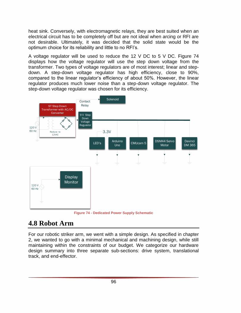
96
heat sink. Conversely, with electromagnetic relays, they are best suited when an electrical circuit has to be completely off but are not ideal when arcing or RFI are not desirable. Ultimately, it was decided that the solid state would be the optimum choice for its reliability and little to no RFI’s.
A voltage regulator will be used to reduce the 12 V DC to 5 V DC. Figure 74 displays how the voltage regulator will use the step down voltage from the transformer. Two types of voltage regulators are of most interest; linear and step-down. A step-down voltage regulator has high efficiency, close to 90%, compared to the linear regulator’s efficiency of about 50%. However, the linear regulator produces much lower noise than a step-down voltage regulator. The step-down voltage regulator was chosen for its efficiency.
120 V
60 Hz Reduce to
12VAC
Arduino
UnoCMUcam 5
9 V Step
Down
Voltage
Regulator
DSM44 Servo
Motor
Davinci
DM 365LED s
SolenoidContact
Relay
3.3V
120 V
60 Hz
Display
Monitor
Figure 74 - Dedicated Power Supply Schematic
4.8 Robot Arm
For our robotic striker arm, we went with a simple design. As specified in chapter 2, we wanted to go with a minimal mechanical and machining design, while still maintaining within the constraints of our budget. We categorize our hardware design summary into three separate sub-sections: drive system, translational track, and end-effector.
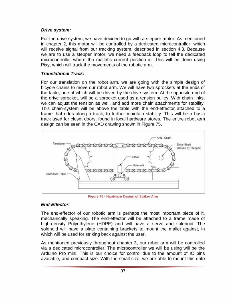
97
Drive system:
For the drive system, we have decided to go with a stepper motor. As mentioned in chapter 2, this motor will be controlled by a dedicated microcontroller, which will receive signal from our tracking system, described in section 4.3. Because we are to use a stepper motor, we need a feedback loop to tell the dedicated microcontroller where the mallet’s current position is. This will be done using Pixy, which will track the movements of the robotic arm.
Translational Track:
For our translation on the robot arm, we are going with the simple design of bicycle chains to move our robot arm. We will have two sprockets at the ends of the table, one of which will be driven by the drive system. At the opposite end of the drive sprocket, will be a sprocket used as a tension pulley. With chain links, we can adjust the tension as well, and add more chain attachments for stability. This chain-system will be above the table with the end-effector attached to a frame that rides along a track, to further maintain stability. This will be a basic track used for closet doors, found in local hardware stores. The entire robot arm design can be seen in the CAD drawing shown in Figure 75.
Figure 75 - Hardware Design of Striker Arm
End-Effector:
The end-effector of our robotic arm is perhaps the most important piece of it, mechanically speaking. The end-effector will be attached to a frame made of high-density Polyethylene (HDPE) and will have a servo and solenoid. The solenoid will have a plate containing brackets to mount the mallet against, in which will be used for striking back against the user.
As mentioned previously throughout chapter 3, our robot arm will be controlled via a dedicated microcontroller. The microcontroller we will be using will be the Arduino Pro mini. This is our choice for control due to the amount of IO pins available, and compact size. With the small size, we are able to mount this onto

98
the housing that the stepper motor will contain. As you can see in section 4.2, we will have an additional Bluetooth module from RedBear that will allow for user control of the robotic arm. This will add another feature and dynamic element to the game experience of Striker. Our wiring diagram for the Arduino Pro mini is shown in the following Figure #. Because our stepper and Servomotors will require more energy than the microcontrollers can provide (+5vdc), we will have to connect the power supply of these to an external source, described in section 4.7. As mentioned earlier in our report, the stepper motors will need four lines connecting to an H-bridge for bi-directional control. This H-bridge, however, can be powered by the on-board Arduino power supply of +5Vdc.
P13SCK
P12MISO
P11MOSI
P10SS1
P09REQN
P08RDYN
P07SS2
P02OUT
P03OUT
P01OUT
P0OUT
P04P06
PWMOUT
P05PWMOUT
SERVO
+5Vdc
GND
POT
STEPPER
ANLGINA0
ARDUINOUNO
RedBear BLEShield
ARDUINO PRO MINI
H-BRIDGE
SN754410NE
EXT.10-30Vdc
SOLENOID
RELAY
Figure 76 - System Wiring Diagram of Robotic Arm
4.9 Puck-Return
The puck-return system has the following requirements:
Puck must be return via the conveyor belt to the player.
Sensor must detect the puck
System must be controlled through Arduino board.
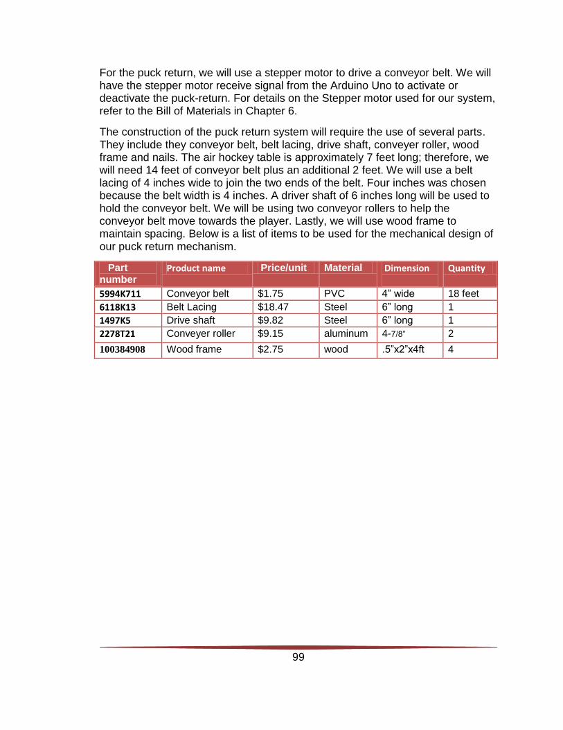
99
For the puck return, we will use a stepper motor to drive a conveyor belt. We will have the stepper motor receive signal from the Arduino Uno to activate or deactivate the puck-return. For details on the Stepper motor used for our system, refer to the Bill of Materials in Chapter 6.
The construction of the puck return system will require the use of several parts. They include they conveyor belt, belt lacing, drive shaft, conveyer roller, wood frame and nails. The air hockey table is approximately 7 feet long; therefore, we will need 14 feet of conveyor belt plus an additional 2 feet. We will use a belt lacing of 4 inches wide to join the two ends of the belt. Four inches was chosen because the belt width is 4 inches. A driver shaft of 6 inches long will be used to hold the conveyor belt. We will be using two conveyor rollers to help the conveyor belt move towards the player. Lastly, we will use wood frame to maintain spacing. Below is a list of items to be used for the mechanical design of our puck return mechanism.
Part number
Product name Price/unit Material Dimension
Quantity
5994K711 Conveyor belt $1.75 PVC 4” wide 18 feet
6118K13 Belt Lacing $18.47 Steel 6” long 1
1497K5 Drive shaft $9.82 Steel 6” long 1
2278T21 Conveyer roller $9.15 aluminum 4-7/8” 2
100384908 Wood frame $2.75 wood .5”x2”x4ft 4
100
5 Prototype and Testing
5.1 Puck Tracking (Pixy)
The main purpose of testing Pixy is to verify that the puck tracking system is capable of producing accurate and reliable data. Additionally, Pixy’s communication protocols must be tested to verify that Pixy and the Ardunio Uno are capable of two-way communication. The following sections further discuss the testing procedure with respect to Pixy.
5.1.1 Coordinate Test
The term coordinate refers to the position of the puck on the table. Pixy has the ability to assign x-coordinates and y-coordinates to objects of interest, with respect to the location of the item within the image originating from the camera of Pixy. The origin is at the top left of the image.
Objective
The objective of coordinate testing is to verify that the coordinates that Pixy produces are accurate and reliable. After testing, the results should demonstrate that Pixy can track the puck continuously and provide usable data.
Equipment
Pixy
Computer
Micro USB to USB cable
Hockey Puck
Procedure
1. Install PixiMon application on the computer 2. Connect Pixy to computer using micro USB to USB cable 3. Teach Pixy to detect the hockey puck by placing it in front of Pixy and press
the button. 4. With the hockey puck placed within the site of Pixy, observe PixyMon and
verify that the hockey puck has been identified. If it has not been identified, repeat step 3.
5. Set PixiMon to display x and y-coordinates of detected objects. 6. While observing PixiMon, move the hockey puck to the top left of the image
and observe the x and y coordinate displayed. The top left should display a value of (0,0). Slowly move the hockey puck to the right and to the bottom, the values of the x and y coordinates should continuously update increased values. If the values do not increase, reteach Pixy to identify the hockey puck
101
and repeat this step. If the values are continuously updated, make sure the cable are connected correctly.
5.1.2 Trajectory Test
In the scope of Striker, trajectory calculations will estimate the position of the hockey puck when it reaches the side the robotic arm. The data used to compute trajectory calculations comes from the coordinates that Pixy assigns to the hockey puck and the change in the coordinates with respect to time.
Objective
The objective of trajectory testing is to verify that Pixy can accurately predict where the air hockey puck will hit on the robotic arms side of the table. If it can calculate the position where it will hit that side accurately, the robotic arm will have the ability to intercept the hockey puck and hit it back to the player.
Equipment
Pixy
Computer
Micro USB to USB cable
Hockey Puck
Air Hockey Table
Procedure
1. Build on the software that comes with Pixy by adding to the code a section that stores previous x and y-coordinates and time elapsed. The code should continuously output at what section of the robotic arm’s side of the air hockey table the air hockey puck will hit. It should predict if the hockey puck is to bounce off a wall first or go straight forward, depending on those two factors, different dynamic analysis will be programmed into the code.
2. Teach Pixy to identify the air hockey puck. Connect Pixy to the computer and mount pixy above the air hockey table to a distance where Pixy can view half of the air hockey table.
3. Hit the air hockey puck at least 30 times and view the output on the computer. Verify if the programming was accurately able to predict where it bounced off the table. A success rate of 75% at this juncture is enough to say, at this stage, that Pixy passed the trajectory test. If a lower rate occurs, rewrite the code as necessary until a success rate of 75% is achieved.
102
5.1.3 SPI Communication Test
Pixy has the capacity to track the hockey puck but the data is useless if it cannot be relayed. We have chosen to use SPI communication to have Pixy communicate with the Arduino Uno. The following sections specify how the testing of communication through SPI will pass the criteria required for the demands of Striker.
Objective
The objective of SPI communication testing is to verify that the data from Pixy can be sent and be useful to the Arduino Uno. The incoming data to the Arduino Uno is continuous; therefore, it is important that the data does not overwrite itself.
Equipment
Pixy
Computer
2 Micro USB to USB cable
Hockey Puck
Air Hockey Table
Arduino Uno
Procedure
1. Improve upon the code for Pixy that was used for trajectory testing and add a section to transmit current coordinates and trajectory coordinates.
2. Write a code for Arduino Uno to receive current coordinates and trajectory coordinates.
3. Connect Pixy and Arduino Uno using the pins that are meant for SPI communications.
4. Connect Pixy to computer. Teach pixy to identify hockey puck. Mount Pixy on top of the air hockey table so that it faces the air hockey table.
5. Connect Arduino Uno to the computer. Open serial communication. 6. Hit the air hockey puck on the air hockey table and verify that the
coordinates and trajectory coordinates are constantly being updated on the serial communications screen. If they are not constantly being updated, verify that the Arduino Uno and Pixy are connected to each other using the appropriate pins. If coordinates are still not updating correctly, alter the codes for Arduino Uno and Pixy.
5.2 Bluetooth
The purpose of our Bluetooth module is to communicate wirelessly to various items within our system. Our module must be able to send and receive data from our Android device, Arduino Uno microcontroller, Pixy (Pixy), and Arduino Pro
103
mini on our robotic arm. The purpose of the tests set forth is to determine that communication can be established with our Bluetooth controller along with control, via external sources.
5.2.1 Wireless connectivity test
Objective
The objective of the wireless connectivity test is to verify that various Bluetooth devices can connect to our Bluetooth module via specified interface method.
Equipment
RedBear BLE Bluetooth Shield
Microchip RN42XV Bluetooth Module
Arduino Uno Board
Pixy Pixy
Android Device
LED (To verify output)
5V DC Power Supply
Procedures
Software Prep:
1. Download the RedBearLab library from: http://redbearlab.com/bleshield/#Quickstart and upload the appropriate library files into the Arduino’s libraries folder.
2. Open the BLEShield Sketch file. 3. Compile and upload the program to the Arduino board. 4. Download and install RedBear’s Android BLE Controller application from
Google Play market. 5. Download the necessary Bluetooth libraries from Arduino’s download site,
http://arduino.cc/en/Main/Software
Hardware Prep:
1. Connect Bluetooth Modules to their respective devices. (Refer to Section 4.2, Figure # for wiring diagram)
2. Verify the voltages to the Bluetooth devices are at least 3.3Vdc or 5Vdc.
Test Procedure:
1. Turn all devices on and run the program downloaded in the software prep. Ensure all ‘power’ LEDs are lit on every device. The voltage to each Bluetooth module and peripheral device should vary between 3.3Vdc to 5.0Vdc.
104
2. Attempt to pair your Android device to the RedBear BLE Shield. Once this has occurred, an LED on the RedBear Shield will light up signaling a paired device.
3. Attempt to connect to the CMUcam Bluetooth module via Android device. Once again, the connection LED on the Bluetooth module should light on once paired.
5.2.2 Wireless Control Test
Objective
The purpose of the wireless control test is to ensure that we can obtain control of devices wirelessly from various devices.
Equipment
RedBear BLE Shield
Microchip RN42XV Bluetooth Module
Arduino Pro Mini
Pixy Pixy
Arduino Uno
Android Device
Stepper Motor
Solenoid
Servomotor
LED (to verify control)
Procedures
1. Perform connectivity test prior to continuing further with Control test. 2. Connect the Stepper, Servo, and Solenoids according to Figure # shown
in section 4.1. 3. Utilize the RedBear application on the Android device to obtain remote
control of the striker arm. This will be done by sending output signals via Bluetooth to the RedBear BLE shield. You can vary the PWM for LED brightness, change direction of the Servomotor via servo control, or turn on/off our stepper motors via digital out. This will verify our remote control of the Striker arm.
4. Write an android application function that will turn on/off an output LED on the Arduino Uno board. This should verify that the Arduino Uno system controller can be controlled Wirelessly via Bluetooth. This will ensure the game setup will turn on the system.
5. Write and run a program onto CMU cam that will send an output via UART to the RN42XV Bluetooth controller. This signal will come from one of the push buttons on the CMUcam board. When the button is pressed, the
105
stepper, servo and solenoids should be energized. This should verify our CMUcam can send signals to the Pro Mini board for processing.
5.3 Robotic Arm
5.3.1 Stepper Motor
Objective
The objective of this test is to assure that the step motor works properly at the right speed and with consistency.
Equipment
Stepper motor Battery ( 9V) Multi-meter
Procedure
1. Check the name plate to make sure the right input voltage is applied otherwise you can burn the motor and every motor comes with a name plate that provides information about the rating, maximum load, and voltage.
2. Use an ohmmeter to find the resistance of the windings. 3. Connect the ohmmeter between the positive input terminal and negative
input terminal of each winding. 4. Compare the resistance values to make sure they are equal. It is
important to find the resistance of the two windings equal exactly the same, otherwise the motor is considered faulty, it must be replaced.
5. After you determine the value of the resistances and find them equal, continue the test by clipping the commons together using a clipper.
6. Use a 9V battery to power the motor and test the motor through its various steps. Use different combination to make sure the motor works properly (clockwise and counterclockwise) placing the battery on any combination of terminals will help you know how the motor should respond. If the motor responds accordingly, it passes the test then you have a good motor; if it fails the test, it needs to be replaced.
5.3.2 Servomotor Test
Objective
The objective of this test is to assure that the Servomotor works properly at the right speed and with consistency.
Equipments
Servomotor
106
Battery ( 9V) Multi-meter
Procedure
1. First, check the name plate to find information about rating, maximum load and voltage In order to supply the right input voltage.
2. Use the ohmmeter to check the ground resistance between the body of the motor and the lead (terminals) and then find the resistance of each lead, which should be the same value.
3. Use the battery to power the motor.
5.4 Arduino Uno
The main purpose of the Arduino Uno is to verify that it is able to receive data, process information, and create meaningful outputs. Striker requires a fast processor of data; therefore, the information processing must occur at fast speeds. The tests developed for the Arduino Uno are meant to encourage efficient programming and its capabilities to manage multiple subsystems.
5.4.1 Lights Test
The Arduino Uno has multiple subsystems it is in charge of. The most basic of these subsystems are the lights that we are going to use on the air hockey table for visual appeal when a goal is scored. It is the first step in testing the Arduino Uno’s capabilities.
Objective
The objective of the lights test is to verify that LED lights can be turned on to flash a particular pattern when triggered by an event. This will prove to us that the Arduino Uno is capable of creating basic decisions. Additionally, it will verify that the lighting subsystem can be implemented.
Equipment
Computer
Micro USB to USB cable
Arduino Uno
10 LED lights
Resistors
Push Button
Breadboard
Procedure
107
1. Write a code for Arduino that checks if a button is pushed. Create a function within that code that flashes the LED lights on and off several times if the button is pushed. Afterwards, it flashes it remains off until the button is pushed again. Download the code to the Arduino.
2. On a breadboard connect push button as an input to the Arduino. Connect the LED lights and resistors to the output of the Arduino Uno.
3. Power the Arduino and press the push button. If the lights do not flash, check the physical connections on the breadboard. Make sure the LEDS are connected to the pin that was referred to as the output pin in the programming. Make sure the push button is connected to the pin referred to as the input pin in the programming. If the LED lights are still not flashing after pressing the button, update the code as necessary.
5.4.2 Goal Sensor Tests
When playing Striker and a goal is scored, special events occur. The player now, will see the lights flash, sounds play, a replay on the screen, and will have the ability to save a replay on their phone. Additionally, scores will be updated. This subsystem is an important part of the achieving the arcade experience that Striker provides to the player. Objective
The objective of the goal sensor tests is to make sure that the PIR sensors is correctly able to detect when the air hockey puck travels through the goal. The Arduino Uno will also go through tests to verify that it can receive communication from the PIR sensors and that it can trigger special events. These tests will build upon the lights test.
Equipment
Computer
Micro USB to USB cable
Arduino Uno
10 LED lights
Resistors
PIR Sensor circuit
Breadboard
Hockey Puck
Procedure
1. Build upon the code written for the lights test by adding code that receives input from the PIR sensor instead of a push button. The PIR sensor is now the input that will make the LED lights flash. Add a section that simulates the tracking of goals scored. Each time the PIR sensor detects the puck, it is to increment a variable that tracks the goals scored.
108
This value will then be displayed on the computer screen through serial communication.
2. Build the circuit that connects to the PIR sensor and LED lights with resistors to the appropriate pins to the Arduino Uno on a breadboard.
3. Connect Arduino Uno to the computer. Pass the hockey puck in front of the PIR sensor. Observe the serial communication on the computer screen and verify that the goal tracking variable is increased. Observe the LEDs and verify that the lights only flash when the hockey puck is detected by the PIR sensor. Repeat this process several times and verify that the appropriate events are triggered by the hockey puck. If the events are not triggered correctly, verify the PIR sensor is connected appropriately and update the code as necessary.
5.4.3 Puck Return Test
The puck return gives the Striker experience the capability of being a non-stop experience. It allows the player to remain in place as the puck returns to the player. Additionally, while the puck returns, the player is distracted with lights, sounds, and replays. Just as the lights are trigged by the PIR sensors, so is the puck return.
Objective
The objective of the puck return test is to verify that a motor can be triggered by the PIR sensor. The test will first confirm that a motor can be commanded by the Arduino Uno without receiving any outside data. When that is confirmed, it will be possible to prove if the PIR sensor can trigger an event in the Arduino to turn the motor on.
Equipment
Computer
Micro USB to USB cable
Arduino Uno
10 LED lights
Resistors
PIR Sensor circuit
Breadboard
Hockey Puck
Motor with circuit
Procedure
1. Write a code to turn on the motor using the Arduino Uno. Make sure to use the pins on the Arduino Uno that are capable of creating pulse width
109
modulation. Make a loop in the code to turn on the motor for 5 seconds and rest for 5 seconds repeatedly.
2. Download the code to the Arduino Uno. Connect the motor circuit to the appropriate pins on the Arduino Uno. Verify that the motor turns on and off repeatedly. If the motor does not turn on and off as expected, make sure the motor circuit is connected appropriately and adjust the code as necessary. Do not continue to step 3 until the motor behaves as expected.
3. Add on to the goal sensors test code by adding the function written in step one to turn on the motor. Change the function to only turn on the motor for five seconds.
4. Download the code to the Arduino Uno. Add to the circuit built in the goal sensors test the motor circuit. Power the Arduino Uno. Pass the hockey puck in front of the PIR sensor. This action should turn on the motor, flash the lights, and display an increase in the goal-scoring variable displayed on the computer through the serial communication of the Arduino Uno. If the motor does not turn on, make sure it is connected appropriately to the circuit and update the code as necessary.
5.4.4 UART/SPI Communication Testing
The Arduino Uno has to communicate through two different methods. The SPI communication method will be used to receive and transmit data from Pixy and to send data to the Arduino Pro Mini. The UART will be used to transmit and receive data from Davinci. It is vital that Arduino Uno is able to manage both communication protocols.
Objective
The objective of these tests is to verify that the Arduino Uno can balance the communication needs required by Pixy and Davinci. Although we are only testing a section of the communication that will actually occur during gameplay, these tests will be sufficient to prove that it can carry out all the required communication.
Equipment
Pixy
Computer
Micro USB to USB cable
Hockey Puck
Air Hockey Table
Arduino Uno
Davinci
LED lights
110
Resistors
Procedure
1. Build upon the code in section 5.1.3 by adding code that will send Davinci a signal to turn on several LED lights when the hockey puck’s current coordinates show that the hockey puck hit the back wall through UART communication.
2. Write a code for Davinci that wait to receive a signal from the Arduino Uno through UART to turn on the LED Lights.
3. Build upon the circuit required for section 5.1.3 by adding the Davinci with appropriate outputs connected to LED lights and resistors.
4. Download the codes to the Pixy, Arduino Uno and Davinci. 5. Hit the puck on the table. Verify that the computer is correctly displaying
current coordinates and trajectory coordinates through the serial communication. Verify that the LED lights connected to the Davinci turn on only when the hockey puck hits the back wall. If the lights do not turn on verify that all components are connected correctly and update the code as necessary.
5.4.5 System Test
The term system in this case refers to the joining of all the subsystems into one system. Although each subsystem is triggered by specific events, they must all synchronize and behave as one entity. The role of the Arduino Uno is to provide that experience.
Objective
The objective of the system test is to verify that the Arduino Uno is able to manage all the inputs and outputs to all the subsystems. By the end of this test, there will be proof that the Arduino Uno is capable of processing the data at rates required by Striker. This test will be the final test required for the Arduino Uno.
Equipment
Pixy
Computer
Micro USB to USB cable
Hockey Puck
Air Hockey Table
Arduino Uno
Davinci
LED lights
Resistors
PIR Sensor circuit
111
Breadboard
Motor with circuit
Procedure
1. Combine the codes from section 5.4.4 and 5.4.3 Change the code so that the Davinci turns on the LED lights only when the Arduino Uno has received input from the PIR sensors that a goal has been scored.
2. Build the circuits as detailed in section 5.4.3 but place the PIR sensor in one of the goals of the air hockey table. Add to it the circuit required by section 5.4.4
3. Download all the codes to the Arduino Uno, Pixy and, Davinci. Hit the puck on the table. Verify that the computer is displaying and updating the current and trajectory coordinates. Score a goal. Observe that the computer is displaying that the goal tracking variable is increased. Observe the LEDs and verify that the lights only flash when the hockey puck is detected by the PIR sensor and that the motor turns on. Hit the puck against the back wall of the hockey table. Verify that the lights from the Davinci only turn on during this event. Repeat this process several times and verify that the appropriate events are triggered by the hockey puck. If the computer is not displaying the appropriate data, update the code as necessary. If the LEDs and motor is not triggering to special events make sure they are connected to the appropriate pins and update code as necessary.
5.5 Davinci Test Procedures
Test procedures for the Davinci are conducted to ensure proper installation of the device. Communication protocols are established such as input from the web camera, communication from the Arduino, and output to the display monitor.
5.5.1 Audio/Video Test
Objective
To determine if the Davinci can receive input from the HD web cam, process the images, and then output the processed signal to the display monitor.
Equipment
Breadboard
Davinci (DM365)
720p HD Web Cam
5 V dc Power Supply
Procedures
112
Software Prep: 1. Download the Linux Digital Video Software Development Kit (DVSDK)
located at this web location: http://www.ti.com/tool/linuxdvsdk-dm36x 2. Install the appropriate software for the DM365 by following these steps:
Unpack the tool chain
Create a target and host shared file system and export it
Set up the build/development environment
Write a simple C-program such as “Hello World” and run it
Follow the steps to install the Gstreamer plug-in at the following
web location:
http://processors.wiki.ti.com/index.php/DMAI_GStreamer_Plug-
In_Getting_Started_Guide
Hardware Prep:
1. Davinci DM 365
2. Breadboard
3. 5 V supply
4. HD Web Cam
5. Monitor
Test Procedure: 1. Test voltage to ensure input voltage is 5 V.
2. Connect HD Web cam to USB 2.0 input of DM 365.
3. Connect the DM 365 to display monitor via HDMI cable.
4. Run the Encode + Decode demonstration program to validate connectivity
5.5.2 LED Strip Test
Test procedures for the LED strips are necessary to ensure proper functionality of the LED lights. Proper communication between Arduino and LED’s needs to be established. Two criteria for the LED design are input from outside stimuli such as the tracking input from Pixy and input from the goal sensors.
Objective
To determine if the Arduino can interact with the LED’s and if they can be manipulated to an expected result verifying communication.
Equipment
Arduino Uno Board
Pixy Pixy (Tracking Protocol)
Goal Sensors
LPD8806 LED Light Strip
113
5 V DC Power Supply
Procedures
Software Prep:
1. Download the Arduino LED library from this web location .
https://github.com/adafruit/LPD8806. Select the Download Zip button and
extract the archive. Rename the uncompressed folder LPD8806 and
confirm that the folder contains the files LPD8806.cpp, LPD8806.h, and
the examples folder.
2. Insert the LPD8806 folder into the Arduino’s libraries folder. It may be
necessary to create the folder if it does not exist.
3. Once the LPD8806 library is installed is installed, restart the Arduino.
Sample code is accessed by directing through the options in this order:
File→Sketchbook→Libraries→LPD8806→strandtest
Hardware Prep: 1. Check voltage readings to insure that output voltage to the LED is 5 V.
2. The strand test is configured based on a one meter LED strip. Connect the
clock_in to pin 3 and data_in to pin 2. Voltage input is connected to a 5
volt source while the ground is connected to the ground on the Arduino.
(Refer to Section 4.5, Figure # for wiring schematic)
Test Procedure: 1. Power up applicable devices. Make sure voltage to the LED’s is 5 volts dc
and not more as this will permanently damage LED’s.
2. Run the example code labeled strandtest. Note that it is written for a 1
meter length strip that contains 32 LED’s. If the LED strip is longer or
shorter then this line of code needs to be augmented:
LPD8806 strip = LPD8806(32, dataPin, clockPin);
The first argument to the object represents the number of LED’s
Count the number of LED’s on the strip being tested (1 meter has
32 LED’s). Change the object number to represent the number of
LED’s being tested.
Run program with newly augmented code base on total number of
LED’s tested.

114
5.6 Power Supply
5.6.1 Transformer Testing
Objective
The objective of this test is to identify if the transformer behaves like a step down transformer. Equipment
Step down transformer Multi-meter
Procedures
1. Isolate the transformer from all power sources 2. Identify the primary side, which is the high side, and the secondary or low
side. Usually this information is provided on the side of the transformer (high side is represented by H1 and H2, low side X1, X2 for example). As a step down transformer the input voltage will come from the high side if not this is not a step down.
3. Use the ohmmeter to calculate the resistance value of each lead. The ohmmeter should read zero ohms. If this is not the case the transformer might be bad.
4. Now connect the leads from the high side together and those from the low side then calculate the resistance value at this point the ohmmeter should read a value if not the transformer needs to be replaced.
5.6.2 Complete System Power
Objective
Our power supply system will be tested differently, since the main system is divided in sub-systems. In this test, we will test each sub-system separately and make sure that the whole system works in harmony.
Equipment
Multi-meter Relay Arduino Uno board Step down transformer Extension plug Voltage regulator LEDs
115
CMU Cam DM365 Servomotor Solenoid
Procedure
1. Test every equipment listed above to make sure they are working properly ( specific test procedure for each is already written in section 5.1)
2. After the individual test is done and everything works accordingly; We will use an extension plug to establish the connection between the receptacle and our system. The extension plug is used to provide more safety in case there is a fault our system will not be affected.
3. Once the system in energized, we will use the multi-meter to check the voltage across each sub-system to assure that the correct amount of voltage is supplied to each one.
4. If everything works according to the plan our system passes the test.
116
6 Administrative Content
6.1 Milestone Discussion
The development of Striker is an arduous task that will be time intensive especially on the functionality of the robot itself. Initially the research process began with the concept of autonomous air hockey table. Further brainstorming was made by observing numerous autonomous robotic air hockey tables from other design teams. At the onset, the most difficult aspect of designing and implementing the autonomous robot would be how the robot tracks the puck’s movement. Execution of the project goals involves intensive research into tracking, hardware and software design.
It became apparent Striker was going to involve a fair amount of programming. Unfortunately, the composition of our team does not include computer engineers. To resolve this shortcoming, we delegated the programming responsibilities to our most qualified team member and chose software options that would make our goals obtainable. Since the primary focus of Striker is tracking, Pixy was chosen and the process of becoming familiar with software started in early October.
Ultimately, success will depend on early planning. Setting milestones to accomplish specific tasks in a timely manner will aid to keep the project on course. Resolution of time management was made by instituting a milestone chart, shown in Figure 77. The milestone chart consists of project deadlines and assignment delegation.
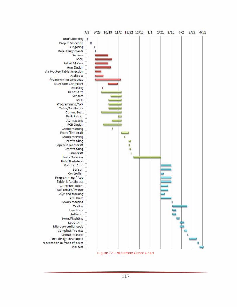
117
Figure 77 – Milestone Gannt Chart

118
6.2 Budgeting and Finance
With most senior design projects, budget and funding will be an intricate part to design success. Estimated funding for Striker was $850 but it was suggested that the Striker budget be set at $1000 to allow for unforeseen issues. It was necessary to seek funding to offset the budget shortfall. Initially the team submitted a proposal to SoarTech for funding. Unfortunately, the monetary award was given to a competing senior design team. Next, the idea of acquiring smaller donations from various connections both professional and personal was discussed. Fortunately, the Striker project is being fully funded by Boeing for $1000. The Boeing funding will give the project design flexibility when development issues arise.
An initial budget outline was assembled to institute monetary constraints on our project to avoid an inordinate amount of personal expense. Our original budget estimate was based on this guideline. The budget can be seen in Table 22.The budget outline was augmented at the creation of the actual parts list created from the hardware design in section 4.
Table 22 – Proposed Budgeting Expenses
Part Description Amount ($)
Air Hockey Table 170.00
Microcontroller 200.00
Visual Effects 120.00
Communications 60.00
Robot Arm 100.00
Servo Motor 60.00
Tracking Cam 20.00
Playback Cam 20.00
Sensors 20.00
Manufacturing 60.00
Puck Return 100.00
Shipping 70.00
Total Budget 1000.00
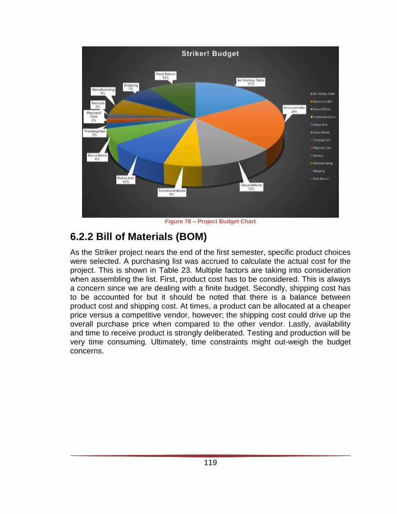
119
Figure 78 – Project Budget Chart
6.2.2 Bill of Materials (BOM)
As the Striker project nears the end of the first semester, specific product choices were selected. A purchasing list was accrued to calculate the actual cost for the project. This is shown in Table 23. Multiple factors are taking into consideration when assembling the list. First, product cost has to be considered. This is always a concern since we are dealing with a finite budget. Secondly, shipping cost has to be accounted for but it should be noted that there is a balance between product cost and shipping cost. At times, a product can be allocated at a cheaper price versus a competitive vendor, however; the shipping cost could drive up the overall purchase price when compared to the other vendor. Lastly, availability and time to receive product is strongly deliberated. Testing and production will be very time consuming. Ultimately, time constraints might out-weigh the budget concerns.
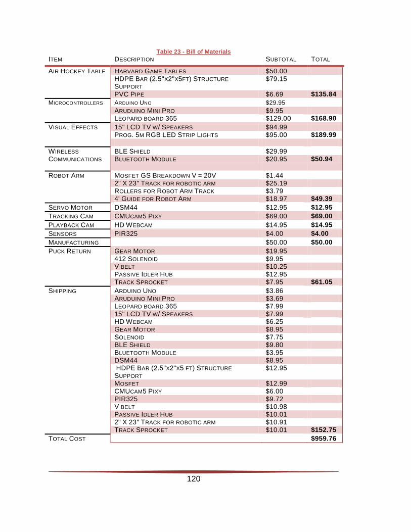
120
Table 23 - Bill of Materials
ITEM DESCRIPTION SUBTOTAL TOTAL
AIR HOCKEY TABLE
HARVARD GAME TABLES $50.00 HDPE BAR (2.5"X2"X5FT) STRUCTURE
SUPPORT $79.15
PVC PIPE $6.69 $135.84
MICROCONTROLLERS
ARDUINO UNO $29.95
ARUDUINO MINI PRO $9.95 LEOPARD BOARD 365 $129.00 $168.90
VISUAL EFFECTS
15" LCD TV W/ SPEAKERS $94.99 PROG. 5M RGB LED STRIP LIGHTS $95.00 $189.99
WIRELESS
COMMUNICATIONS
BLE SHIELD $29.99 BLUETOOTH MODULE $20.95 $50.94
ROBOT ARM
MOSFET GS BREAKDOWN V = 20V $1.44 2" X 23" TRACK FOR ROBOTIC ARM $25.19 ROLLERS FOR ROBOT ARM TRACK $3.79 4' GUIDE FOR ROBOT ARM $18.97 $49.39
SERVO MOTOR DSM44 $12.95 $12.95
TRACKING CAM CMUCAM5 PIXY $69.00 $69.00
PLAYBACK CAM HD WEBCAM $14.95 $14.95
SENSORS PIR325 $4.00 $4.00
MANUFACTURING $50.00 $50.00
PUCK RETURN
GEAR MOTOR $19.95 412 SOLENOID $9.95 V BELT $10.25 PASSIVE IDLER HUB $12.95 TRACK SPROCKET $7.95 $61.05
SHIPPING ARDUINO UNO $3.86 ARUDUINO MINI PRO $3.69 LEOPARD BOARD 365 $7.99 15" LCD TV W/ SPEAKERS $7.99 HD WEBCAM $6.25 GEAR MOTOR $8.95 SOLENOID $7.75 BLE SHIELD $9.80 BLUETOOTH MODULE $3.95 DSM44 $8.95 HDPE BAR (2.5"X2"X5 FT) STRUCTURE
SUPPORT $12.95
MOSFET $12.99 CMUCAM5 PIXY $6.00 PIR325 $9.72 V BELT $10.98 PASSIVE IDLER HUB $10.01 2" X 23" TRACK FOR ROBOTIC ARM $10.91 TRACK SPROCKET $10.01 $152.75
TOTAL COST $959.76

121
The projected budget and the price list are very similar for the percentage breakdown of money allocated for resources that is illustrated in Figure 78. One exception, there was more money spent for visual effects than anticipated. Originally, visual effects were budgeted for $120 but the actual cost is about $190, making Striker $70 over budget for this resource. However, other areas had less spending. Cost for the robot arm materials is approximately $50 while the proposed budget was $100. The largest discrepancy in resource allocation was for shipping where the actual cost more than doubled the projected budget. In all, Striker is $40 under budget.
Figure 79 - Bill of Materials Chart
6.3 Sponsors and Contributors
We would like to thank Boeing for their generous contribution of $1000 to fund our design project Striker. The more than adequate funding will ease the financial burden to make Striker possible.
In addition, we would like to thank Power Grid Engineering for the funding that is being offered. Their thoughtful consideration for our project is greatly appreciated.
Lastly, we would like to thank Universal Studios, Orlando for allowing us to utilize their resources for our project. Any help is greatly appreciated.
On behalf of the University of Central Florida, we thank you!
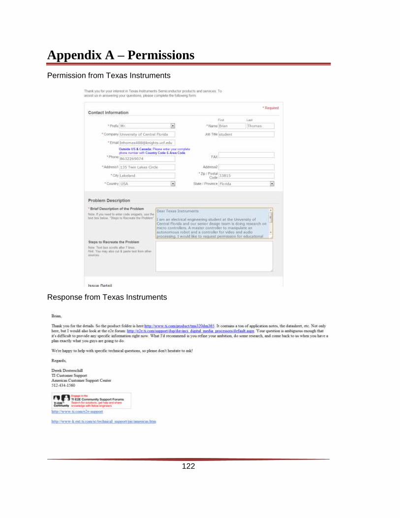
122
Appendix A – Permissions
Permission from Texas Instruments
Response from Texas Instruments
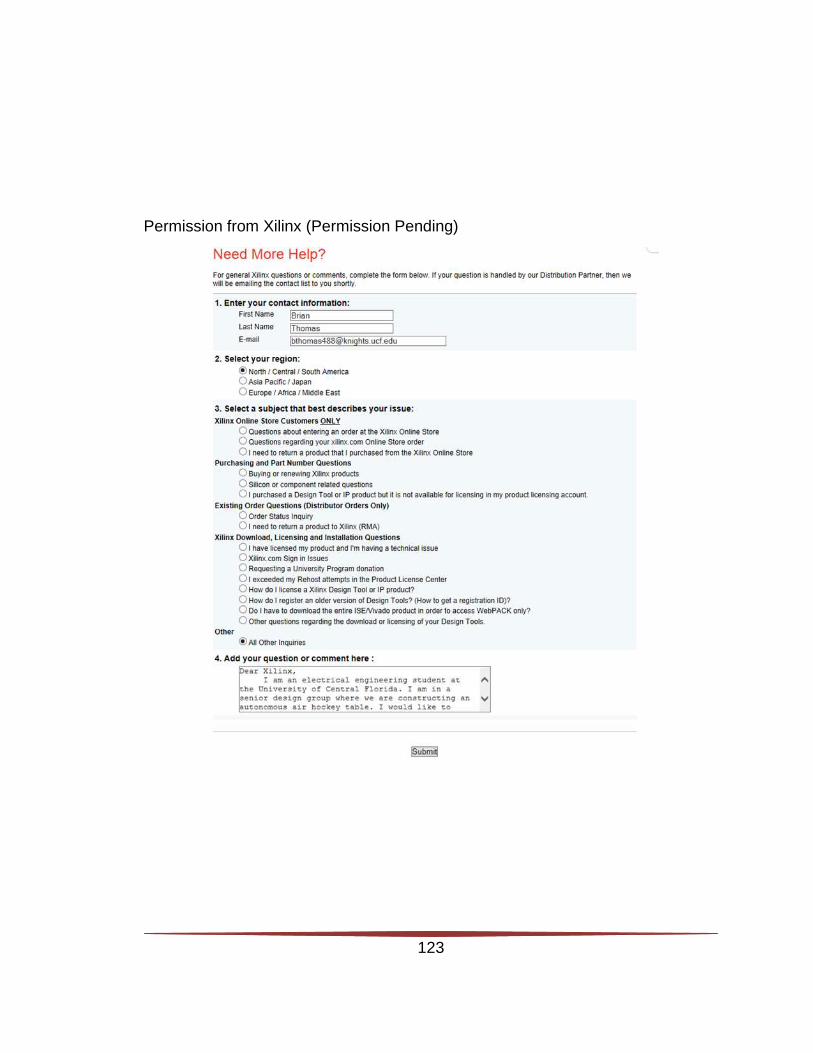
123
Permission from Xilinx (Permission Pending)

124
Xilinx Copyright Statement
Permission and Response from Pixy By Charmed Labs and Carnegie Melon

125
Permission from Glolab
Permission granted by Glolab
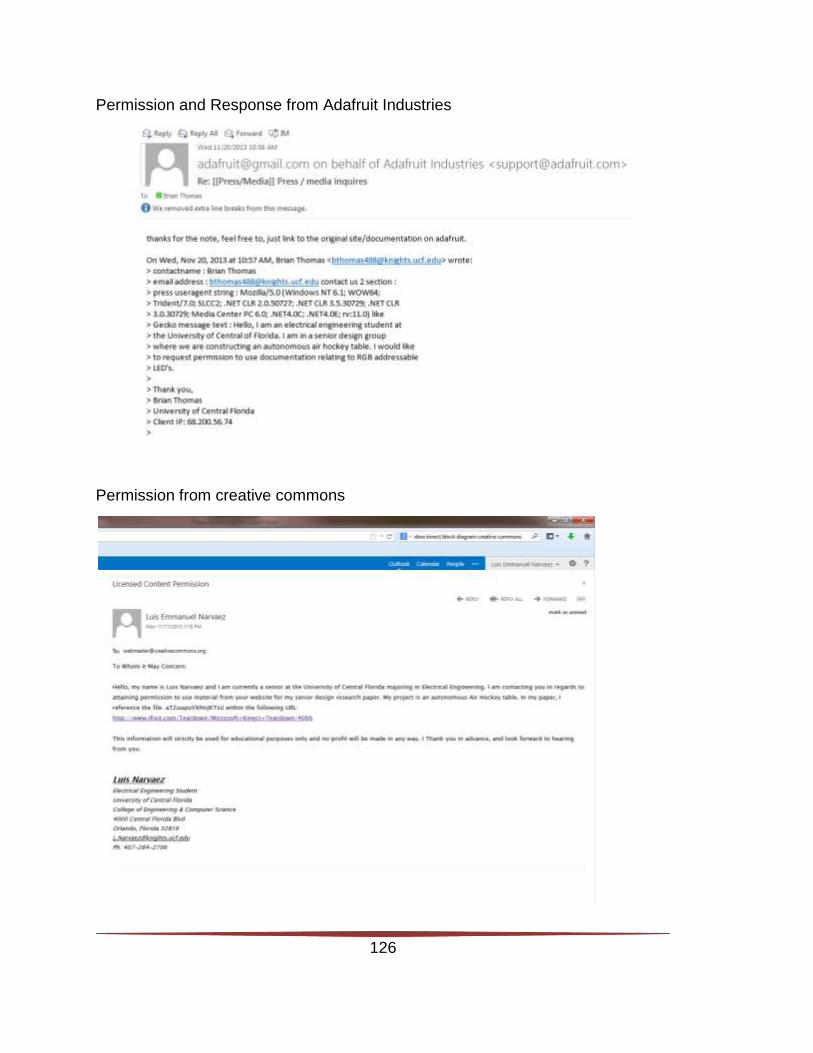
126
Permission and Response from Adafruit Industries
Permission from creative commons
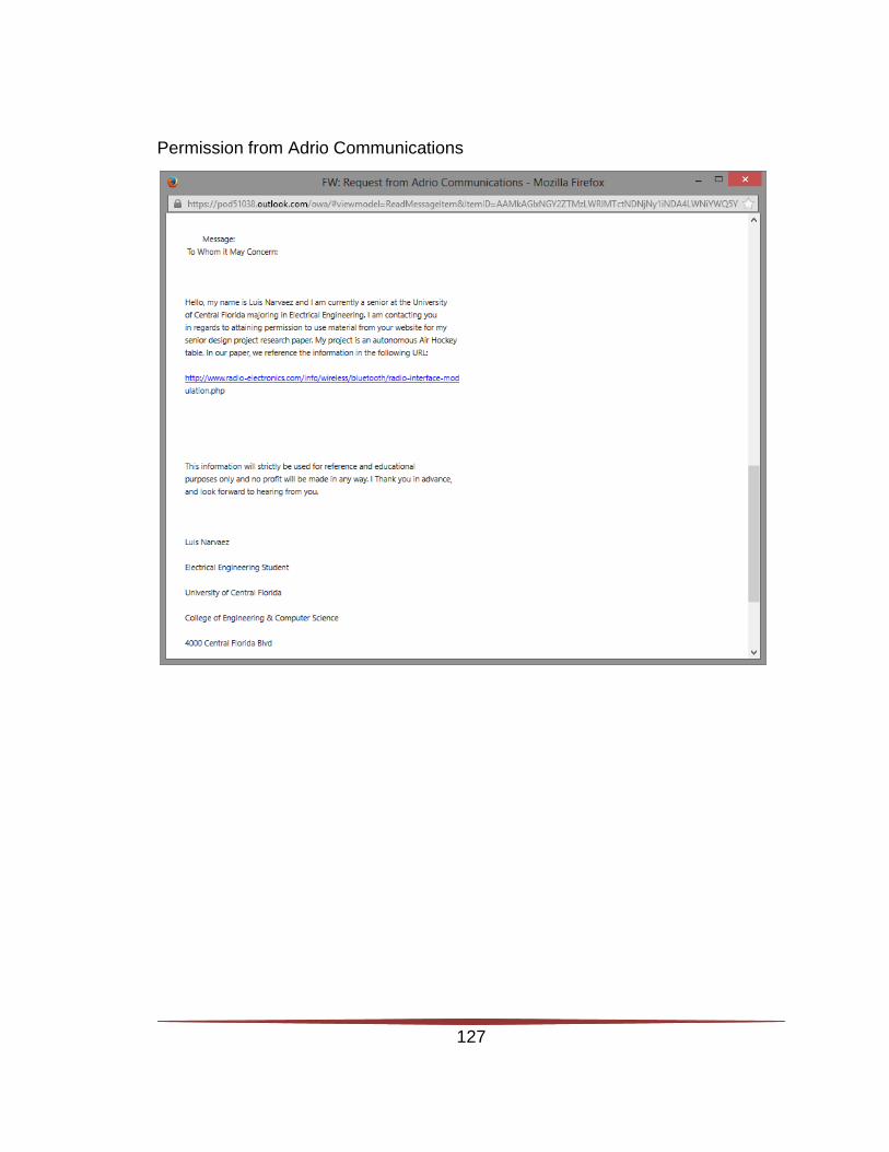
127
Permission from Adrio Communications
128
Response Adrio Communications
129
Permission from ConnectBlue
130
Response from ConnectBlue
131
Permission From Pepperl Fuschs
132
Response from Pepperl Fuschs
133
Permission from Atmel
Response from Atmel
134
Permission from Arduino
Response from Arduino
Permission from Glolab

135
Response from Glolab
Permission from Azega (Pending)
136
Permission from New Electronics
Response from New Electronics
137
Permission from Yes I Can – Science (Pending)
Permission for HeaterPlus.com (Pending)
138
Permission for Engineers Garage (Pending)
Permission from Oriental Motor (Pending)
139
SPI Shift diagram
140
ACME ROD
SPI Daisy-chain pics:
141
I2C Timing Diagram:
142
Appendix B – Figures and Tables Index
Table 1 - Statistics Being Tracked for Leader boards ...................................................................... 5 Figure 1 - Mobile Application Main Menu ......................................................................................... 5 Figure 2 - Audio & Video Control Block Diagram ............................................................................. 7 Table 2 - Microcontroller Monitored I/O ......................................................................................... 11 Figure 6: XBOX 360 Kinect Block Diagram ................................................................................... 14 Figure 7: LPC4357 Internal Block Diagram [5] (Permission from NXP pending) .......................... 16 Table 3 - CMUcam Feature Comparison [3][4] .............................................................................. 17 Figure 9 - Pixy's Hardware Interface [10] (Permission Obtained from Charmed Labs) ................. 20 Figure 10 – Pixy’s pin layout for the I/O ports [10] (Permission Obtained from Charmed Labs) ... 21 Table 4 - Data Block Packet Sizes [10] .......................................................................................... 21 Figure 10 - Internal Components of a Photoelectric Sensor [11] (Permission Obtained from
Pepperl-Fuchs) ....................................................................................................................... 23 Figure 11 - Retro-Reflective Sensor Instrumentation [11] (Permission Obtained From Pepperl-
Fuchs) .................................................................................................................................... 24 Figure 12 - Light On/ Dark On Condition Chart [12] (Permission Obtained from Pepperl-Fuchs) . 25 Figure 13: (a) Wiring Diagram of Pepperl-Fuchs MLV12-54-LAS/76b/110/124 (b) M12 Pin
Configuration (c) M12 Housing Sensor [13] (Permission Obtained from Pepperl-Fuchs) ..... 26 Figure 14 - Passive Infrared Sensors (a) Front (b) Back [14](Permission pending from Ladyada)
............................................................................................................................................... 27 Figure 15 – PIR Sensor Operational Block Diagram [15] (Permission Obtained From Glolab) .... 27 Table 5 – PIR Sensor Specifications [15] ...................................................................................... 28 Figure 16 - BISS001 Chip PIR Motion Detector IC [16] (Permission pending from Ladyada) ...... 28 Figure 17 – (a) Photodiode [17](Permission Pending from Thor Labs) (b) Inner construction of a
Photodiode [18] (Permission Pending from T.R. Kuphaldt) ................................................... 29 Figure 18 - Two Phase Permanent Magnet Stepper [19] (Permission pending from ‘Garage’) .... 30 Figure 19 - Two-Phase Variable Reluctance Motor [19] ................................................................ 31 Figure 20 - Two-Phase Hybrid Motor Construction [19] ................................................................ 31 Figure 21 - Stepper Motor Drive system Diagram [20] (Pending permission from Oriental Motor
USA) ....................................................................................................................................... 32 Figure 22 - 5mm Hybrid Stepper Motor [21] (Permission pending from Pololu) ............................ 32 Table 6 - Characteristics of 5mm Stepper Motor [21] .................................................................... 32 Table 7 - Stepper Motor Comparison Chart ................................................................................... 33 Figure 23 - Stepper Motor Interfacing with Arduino [22] (Permission pending from “Azega”) ....... 33 Figure 24 - Conceptual Drawing of Bidirectional Striker ................................................................ 34 Figure 25 - Wheel mask for rotary Encoder [23] (Permission obtained from “ScienceProg”) ....... 36 Figure 26 - (a) Rotary Potentiometer used in Electronic Circuits.[24] (Permission Pending from
"Futurelec") [25] (b) Internal Makeup of rotary Potentiometer. Notice that terminals ‘A’ and ‘B’ provide physcal limit on rotation as well as return voltage. [25] (Permission Pending from "Fedderson") .......................................................................................................................... 36
Table 8 - Specifications of several DC Motors ............................................................................... 37 Figure 27 - Functioncal Block Diagram of Servomotor System ..................................................... 39 Table 9 - Characteristics of Various DC Servomotors ................................................................... 40 Figure 28 - PWM of a servomotor [28] (Permission pending from “Engineers Garage”)............... 40 Figure 29 - Interfacing a Servomotor to Arduino via PWM [29] (Permission pending from “Azega”)
............................................................................................................................................... 41 Table 10 - Comparison of various Solenoids ................................................................................. 41 Figure 30 - Conceptual Drawing of Translational Track ................................................................ 42 Figure 31 - ACME Rod Threading [30] (Permission Pending from “Crapworks”) .......................... 43 Figure 32 - C5000 Audio Capacitive Booster Pack [32] (Permission pending from “Texas
Instruments”) .......................................................................................................................... 45
143
Figure 33 - Functional Block Diagram of C5000 Booster Pack and MSP430 Launch Pad [33] (Permission pending from Texas Instruments) ...................................................................... 45
Figure 34 - Microprocessor System Architecture vs. DSP System Architecture ........................... 46 Figure 35 - Block Diagram of H.264 Video Codec ......................................................................... 48 Figure 36: VGA Connections from Spartan 3 Starter Board [45] (Permission Pending from
‘Xylilnx’) .................................................................................................................................. 50 Figure 37 - Block Diagram of DM365 [36] (Permission from Texas Instruments) ......................... 51 Figure 38 – VPSS/VPFE Internal Block Diagram [40] (Permission Pending from “Texas
Instruments”) .......................................................................................................................... 52 Figure 39 - OSD and VENC Modules within VPBE [41] (Permission pending from ‘Texas
Instruments’) .......................................................................................................................... 53 Figure 40 - DMAI Block Diagram ................................................................................................... 54 Table 11: Voltage and Current Requirements for HL 1606 ........................................................... 55 Figure 41: HL 1606 Chip for LED Strip [45] (Permission Obtained from Adafruit) ........................ 56 Figure 42: Gray Scale Data Format of WS2801 [46] (Permission Obtained from Adafruit) .......... 56 Figure 43 - LDP8806 LED Light Strip [45](Permission Obtained from Adafruit) ............................ 57 Figure 44 - PWM Duty Cycles[47] (Permission Obtained from Arduino) ....................................... 58 Table 12 – Wireless Communication System Comparisons .......................................................... 58 Table 13 - Bluetooth Power Classes .............................................................................................. 59 Figure 45 - Bluetooth 4.0 (BLE) Gateway Diagram ....................................................................... 60 Figure 46 - UART Interfacing of Bluetooth Module with Arduino [49] (Permission pending from
Amicus) .................................................................................................................................. 62 Figure 47 - SPI Master / Slave Communication Process [50] (Permission pending from
RoboTosh).............................................................................................................................. 63 Figure 48 SPI Independent (left) and daisy chain (right) configurations [51] (Permission pending
from T. Kugelstadt) ................................................................................................................. 63 Figure 49 - I
2C Interface (shown without pullup resistors) ............................................................. 64
Figure 50 - Timing diagram for I2C interfacing [52] (Permission pending from Sidharth) .............. 65
Table 14 - MSP430FG4618 Specifications [53] ............................................................................. 67 Figure 51 - Arduino Uno Development Board [26] (Permission obtained from Arduino) ............... 68 Table 15 Arduino Uno Development Board Features [26] ............................................................. 69 Table 16 - Digital Pin Use Summary [26] ....................................................................................... 70 Table 17 - Interface ports of various Arduino Boards .................................................................... 71 Figure 52 - Transformer Input/Output Characteristics of Step-down (Left) and Step-up (Right)
Transformers [54] (Permission pending from ‘yesican’) ........................................................ 73 Table 18 - Transformer Comparison Chart .................................................................................... 73 Figure 53 - Single-phase Solid-State Relay [55] (Permission pending from MOR Electric) .......... 74 Figure 54 - Electromechanical Relay construction.[56] (Permission pending from 'New
Electronics') ............................................................................................................................ 74 Figure 55 - System Wiring Overview with Pins .............................................................................. 78 Figure 56 - H-Bridge and Stepper Motor Connection with Arduino Pro Mini ................................. 79 Figure 57 - Solenoid Interfacing with Arduino Pro Mini .................................................................. 79 Table 19 - Comparison Chart of Bluetooth Modules ...................................................................... 80 Table 20 - ACI Pin Assignments between Arduino Pro and RedBear BLE ................................... 81 Figure 58 - Wireless Communication Wiring Schematic ................................................................ 82 Table 21 - Comparison of Tracking Systems ................................................................................. 83 Figure 59 - Wiring between RN42XV Bluetooth Module and Pixy ................................................. 83 Figure 60 - Pixy CPU: LPC4330 Dual-Core Schematic [4] (Permission Obtained from Charmed
Labs) ...................................................................................................................................... 84 Figure 61 - OmniVision OV915 CMOS Image Sensor Schematic [4] (Permission Obtained from
Charmed Labs) ...................................................................................................................... 85 Figure 62 - SPI and USB2.0 Interface. All ports are ESD protected via ESDR0502B chip.[4] ...... 86 Figure 63 - Pixy Embedded 5V, 3.3V, and 1.5V Voltage Regulators.[4] ....................................... 87
144
Figure 64 - DM365 UART Interface Reference Diagram [36] (Permission Granted from T.I.) ...... 88 Figure 65 - Peripheral AV Connection Diagram............................................................................. 89 Figure 66 - Connection of LPD8806 to Arduino Uno [45](Permission Granted from Adafruit) ...... 90 Figure 67 - Arduino Uno Coding Flow chart ................................................................................... 90 Figure 68 - Arduino Pro Mini Coding Flow Diagram ...................................................................... 91 Figure 69 Android Application Coding Diagram ............................................................................. 92 Figure 70: Video Playback Flowchart ............................................................................................ 93 Figure 71 - LED Lighting Coding Flow Diagram ............................................................................ 94 Figure 72 - LED Puck-Shadowing Code Diagram ......................................................................... 94 Figure 73 – PIR325 goal Sensor Wiring Diagram .......................................................................... 95 Figure 74 - Dedicated Power Supply Schematic ........................................................................... 96 Figure 75 - Hardware Design of Striker Arm .................................................................................. 97 Figure 77 – Milestone Gannt Chart .............................................................................................. 117 Table 22 – Proposed Budgeting Expenses.................................................................................. 118 Figure 78 – Project Budget Chart ................................................................................................ 119 Table 23 - Bill of Materials ............................................................................................................ 120 Figure 79 - Bill of Materials Chart ................................................................................................ 121
145
Appendix C – Works Cited
[1] C. P. E, K. R. G and L. R. W, "Air Cushion Table Game". United States of America Patent US3773325, 20 November 1973.
[2] M. McWhertor, "Kotaku," 20 April 2010. [Online]. Available: http://kotaku.com/5520812/project-natal--its-instruction-manual-in-the-wild?comment=22017469#comments. [Accessed 28 October 2013].
[3] CMUcam, "CMUcam:Open Source Programmable Embedded Color Vision Sensors," 2011. [Online]. Available: http://www.cmucam.org/projects/cmucam4/. [Accessed 1 November 2013].
[4] CMUcam, "CMUcam5 Pixy," 13 August 2013. [Online]. Available: http://www.cmucam.org/projects/cmucam5/wiki/Wiki. [Accessed October 2013].
[5] NXP Semiconductors, "LPC4300 User Manual - CMUcam5 Pixy - CMUcam: Open Source Programmable Embedded Color Vision Sensors:," 5 September 2012. [Online]. Available: http://www.cmucam.org/documents/20. [Accessed 27 November 2013].
[6] OpenCV, "OpenCV," OpenCV, 30 November 2013. [Online]. Available: opencv.org.
[7] OpenCV, "OpenCV," Itseez, 11 November 2013. [Online]. Available: opencv.org.
[8] Charmed Labs and Carnegie Mellon, "CMUcam4 Arduino Interface Library," Charmed Labs, 10 February 2013. [Online]. Available: http://www.cmucam.org/docs/cmucam4/arduino_api/.
[9] Charmed Labs and Carnegie Mellon, "Color Tracking Explanation," Charmed labs, 30 November 2013. [Online]. Available: http://www.cmucam.org/projects/cmucam4/wiki/Color-tracking_Explanation.
[10] Charmed Labs and Carnegie Mellon, "Pixy (CMUcam5): a fast, easy-to-use vision sensor," Charmed labs, 14 September 2013. [Online]. Available: http://www.kickstarter.com/projects/254449872/pixy-cmucam5-a-fast-easy-to-use-vision-sensor.
[11] Pepperl+Fuchs, "Files: Pepperl-Fuchs," 21 October 2008. [Online]. Available: http://files.pepperl-
146
fuchs.com/selector_files/navi/productInfo/doct/tdoct1633__usa.pdf. [Accessed October 2013].
[12] M. Turner, "Blogs: Pepperl+Fuchs," 16 July 2013. [Online]. Available: http://blog.pepperl-fuchs.us/blog/bid/290513/What-s-the-Difference-Between-Light-ON-and-Dark-ON-Modes-for-Photoelectric-Sensors. [Accessed October 2013].
[13] Pepperl-Fuchs GmbH, "Files: Pepperl+Fuchs," 3 February 2004. [Online]. Available: http://files.pepperl-fuchs.com/selector_files/navi/productInfo/edb/128098_eng.pdf. [Accessed October 2013].
[14] Glolab, "How to use Pyroelectric ("Passive") Infrared Sensors (PIR," , 27 April 2012. [Online]. Available: http://www.ladyada.net/learn/sensors/pir.html. [Accessed 30 november 2013].
[15] Glolab, "How Infrared Motion Detector Components Work: , 23, 2013 5:50:45 PM," 23 November 2013. [Online]. Available: http://www.glolab.com/pirparts/infrared.html. [Accessed 30 November 2013].
[16] Ladyada.net, "BISS0001 Micro Power PIR Motion Detector," [Online]. Available: http://www.ladyada.net/media/sensors/BISS0001.pdf. [Accessed 22 November 2013].
[17] Thorlabs, "Thorlabs - FGAP71 GaP Photodiode, 1 ns Rise," [Online]. Available: http://www.thorlabs.com/images/xlarge/12174-xl.jpg. [Accessed November 2013].
[18] T. R. Kuphaldt, "Special-purpose diodes," 29 March 2009. [Online]. Available: http://www.allaboutcircuits.com/vol_3/chpt_3/12.html. [Accessed November 2013].
[19] Stepper Motors or Step Motors : Tutorial with Basics, working & types of Stepper Motor – EngineersGarage, "Stepper Motors or Step Motors : Tutorial with Basics, working & types of Stepper Motor – EngineersGarage," [Online]. Available: http://www.engineersgarage.com/articles/stepper-motors?page=3. [Accessed 30 November 2013].
[20] "VEXTA Stepper Motors, Drivers and Controllers," [Online]. Available: http://www.orientalmotor.com/products/stepper-motors/. [Accessed 30 Novenber 2013].
[21] "Pololu - Stepper Motor: Bipolar," [Online]. Available: http://www.pololu.com/product/1207. [Accessed 30 November 2013].
147
[22] Azega, "Controlling a Stepper Motor with an Arduino," [Online]. Available: http://www.azega.com/controlling-a-stepper-motor-with-an-arduino/. [Accessed 30 November 2013].
[23] ScienceProg, "ScienceProg.com," 4 May 2007. [Online]. Available: http://www.scienceprog.com/using-gray-code-for-rotary-encoders/. [Accessed 21 November 2013].
[24] Futurlec, "Futurlec.com," 2013. [Online]. Available: http://www.futurlec.com/Components.shtml. [Accessed 21 November 2013].
[25] J. Feddersen, "http://fddrsn.net/pcomp/examples/potentiometers.html," [Online]. Available: http://fddrsn.net/pcomp/examples/potentiometers.html. [Accessed 21 November 2013].
[26] Arduino, "Arduino Uno," [Online]. Available: http://arduino.cc/en/Main/ArduinoBoardUno. [Accessed 20 November 2013].
[27] Society of Robots, "How to Build a Robot Tutorials - Society of Robots," Society of Robots, 30 November 2013. [Online]. Available: http://www.societyofrobots.com/actuators_dcmotors.shtml.
[28] "Servo Motor Tutorial | DC Servo Motor Control - Basics & Working of Servos - EngineersGarage," [Online]. Available: http://www.engineersgarage.com/articles/servo-motor?page=2. [Accessed 30 November 2013].
[29] Azega, "Arduino Servo Motor," [Online]. Available: http://www.azega.com/arduino-servo-motor-part-1/. [Accessed 29 November 2013].
[30] BigAl, "The Crapworks: Upgrading from all thread to trapezoidal ACME leadscrews," 20 November 2011. [Online]. Available: http://crapworks.blogspot.com/2011/11/upgrading-from-all-thread-to.html. [Accessed 29 November 2013].
[31] United States Air Association, "Pro Air Hockey," [Online]. Available: http://www.proairhockey.com/USAA_Rules.pdf. [Accessed 22 November 2013].
[32] Texas Instruments, "C5000 Audio Capacitive Touch BoosterPack," 2012. [Online]. Available: http://www.ti.com/tool/430boost-c55audio1#2. [Accessed 23 November 2013].
[33] Texas Instruments, "Audio Capacitive Touch BoosterPack Hardware," 28 March 2013. [Online]. Available:
148
http://processors.wiki.ti.com/index.php/Audio_Capacitive_Touch_BoosterPack_Hardware. [Accessed 25 November 2013].
[34] S. Somers, "Digital Signal Processing Reshaping Your Perceptual Enviroment One Digital Sample at a Time," 2010. [Online]. Available: http://www.extron.com/company/article.aspx?id=digisigproc_ts. [Accessed 24 November 2013].
[35] J. Golston, "Comparing Media Codecs for Video Content," San Francisco, 2004.
[36] Texas Instruments, "Davinci DM3x SOC," June 2011. [Online]. Available: http://www.ti.com/product/tms320dm365. [Accessed 15 November 2013].
[37] Xilinx, "Xilinx All Programmable," 20 June 2008. [Online]. Available: http://www.xilinx.com/support/documentation/boards_and_kits/ug130.pdf. [Accessed 15 November 2013].
[38] National Instruments, "National Instruments," 16 April 2012. [Online]. Available: http://www.ni.com/white-paper/6984/en/. [Accessed 2 November 2013].
[39] Xilinx, "XA Spartan-3E Automotive," 9 September 2009. [Online]. Available: http://www.xilinx.com/support/documentation/data_sheets/ds635.pdf. [Accessed 22 November 2013].
[40] Texas Instruments, "TMS320DM36x Digital Media System-on-Chip (DMSoC) Video Processing Front End (VPFE)," November 2010. [Online]. Available: http://www.ti.com/lit/ug/sprufg8c/sprufg8c.pdf. [Accessed 25 November 2013].
[41] Texas Instruments, "TMS320DM36x Digital Media System-on-Chip (DMSoC) Video Processing Back End (VPBE)," July 2010. [Online]. Available: http://www.ti.com/lit/ug/sprufg9c/sprufg9c.pdf. [Accessed 27 November 2013].
[42] Texas Instruments, "GSG: DVEVM Software Setup for DM3xx Platforms," 22 June 2011. [Online]. Available: http://processors.wiki.ti.com/index.php/GSG:_DVEVM_Software_Setup_for_DM3xx_Platforms. [Accessed 28 November 2013].
[43] Texas Instruments, "DMAI GStreamer Plug-In," 12 July 2011. [Online]. Available: http://processors.wiki.ti.com/index.php/DMAI_GStreamer_Plug-In. [Accessed 28 November 2013].
149
[44] A. Castle, "Jamie & Adam Tested," 21 February 2013. [Online]. Available: http://www.tested.com/art/makers/453665-how-get-started-programmable-rgb-led-strip-lighting/. [Accessed 20 November 2013].
[45] "Adafruit.com," [Online]. Available: http://www.adafruit.com/products/306. [Accessed 20 November 2013].
[46] Adafruit, November 2008. [Online]. Available: http://www.adafruit.com/datasheets/WS2801.pdf. [Accessed 22 November 2013].
[47] T. Hirzel, "PWM," Arduino, [Online]. Available: http://arduino.cc/en/Tutorial/PWM. [Accessed 27 November 2013].
[48] I. Poole, "Bluetooth radio interface, modulation, & channels," Adrio Communications Ltd, [Online]. Available: http://www.radio-electronics.com/info/wireless/bluetooth/radio-interface-modulation.php. [Accessed November 2013].
[49] Les, "Amicus 18 - Port Expansion using SPI," 6 March 2010. [Online]. Available: http://www.click-server.com/amicus/Port%20Expansion/Higher%20Res%20Images/Master%20to%20Slave%20Interaction.png. [Accessed October 2013].
[50] "roboToSH," 07 July 2012. [Online]. Available: http://2.bp.blogspot.com/-pnK3I1l-Qhw/T_wf75kTbwI/AAAAAAAABkA/mRFDJ93tpbw/s400/Arduino+Bluetooth.png. [Accessed October 2013].
[51] T. Kugelstadt, "SIGNAL CHAIN BASICS (Part 31): Digital interfaces (con't) -- The SPI Bus | EE Times," 15 July 2009. [Online]. Available: http://m.eet.com/media/1051315/C0434-Figure2.gif. [Accessed October 2013].
[52] Siddharth, "Are you reading the datasheet? What to look for and how to find them!," 12 November 2013. [Online]. Available: http://embedjournal.com/2013/11/are-you-reading-the-datasheet/. [Accessed November 2013].
[53] "MSP430 Microcontroller | 16 bit Microcontroller | 16 bit MCU," [Online]. Available: http://ww.ti.com/sds/ti/microcontroler/16-bit_msp430/overview. [Accessed 30 November 2013].
[54] "Transformers," [Online]. Available: http://resources.yesican-science.ca/magnets/transformers.html. [Accessed 30 November 2013].
150
[55] "Solid State Power Controls," [Online]. Available: http://www.heatersplus.com/payne.html. [Accessed 27 November 2013].
[56] "Electromechanical relays still have much to offer," [Online]. Available: http://www.newelectronics.co.uk/electronics-technology/electromechanical-relays-still-have-much-to-offer/44279/(%20%20electro-mec. [Accessed 30 November 2013].
[57] Open Handset Alliance, "Industry Leaders Announce Open Platform for Mobile Devices," Open Handset Alliance, 5 November 2007. [Online]. Available: http://www.openhandsetalliance.com/press_110507.html.
[58] Canalys, "Google's Android becomes the world's leading smart phone platform," Canalys, 31 January 2011. [Online]. Available: http://www.canalys.com/newsroom/google%E2%80%99s-android-becomes-world%E2%80%99s-leading-smart-phone-platform.
[59] D. Kerr, "Windows Phone brings global competition to iOS and Android," CNet, 2 September 2013. [Online]. Available: http://news.cnet.com/8301-1035_3-57601007-94/windows-phone-brings-global-competition-to-ios-and-android/.
[60] J. Rosenberg, "Google Play hits 25 billion downloads," Google, 26 September 2012. [Online]. Available: http://officialandroid.blogspot.com/2012/09/google-play-hits-25-billion-downloads.html.
[61] Android, "Eclipse-ADT," Google, 30 November 2013. [Online]. Available: http://developer.android.com/tools/sdk/eclipse-adt.html.
[62] M. Honan, "Apple Unveils iPhone," Macworld, 9 January 2007. [Online]. Available: http://www.macworld.com/article/1054769/iphone.html.
[63] S. Costello, "How many apps are in the iPhone App Store?," About.com, 30 November 2013. [Online]. Available: http://ipod.about.com/od/iphonesoftwareterms/qt/apps-in-app-store.htm.
[64] B. H. Frank, "Microsoft unifies Windows and Windows Phone developer programs," GeekWire, 6 November 2013. [Online]. Available: http://www.geekwire.com/2013/microsoft-unifies-windows-windows-phone-developer-programs/.
[65] Apple, "Which Developer Program is for you?," Apple, 30 November 2013. [Online]. Available: https://developer.apple.com/programs/which-program/.
151
[66] J. Topolsky, "Windows Phone 7 luanch guide," Engadget, 2010. [Online]. Available: http://www.engadget.com/2010/10/11/windows-phone-7-launch-guide/.
[67] R. E. i. Chief, "windows Phone doubles in market share, currently word's fastest growing smartphone platform," WinBeta, 31 October 2013. [Online]. Available: http://www.winbeta.org/news/windows-phone-doubles-market-share-currently-worlds-fastest-growing-smartphone-platform.
[68] Texas Instruments, "Davinci Multimedia Application Interface," 22 August 2013. [Online]. Available: http://processors.wiki.ti.com/index.php/Davinci_Multimedia_Application_Interface. [Accessed 28 November 2013].
[69] T. R. Mahaffey, "Electronic Design," 15 September 2002. [Online]. Available: http://electronicdesign.com/components/electromechanical-relays-versus-solid-state-each-has-its-place. [Accessed 29 November 2013].
[70] Analog Devices Inc., "Understanding How Voltage Regulators Work," 2009. [Online]. Available: http://www.analog.com/en/content/ta_fundamentals_of_voltage_regulators/fca.html. [Accessed 29 November 2013].
[71] Arduino, "Arduino," 30 November 2013. [Online]. Available: arduino.cc.
[72] Windows, "Windows Phone SKD," Windows, 30 November 2013. [Online]. Available: http://dev.windowsphone.com/en-us/downloadsdk.
[73] Windows, "Getting started with developing for Windows Phone," Windows, 4 November 2013. [Online]. Available: http://msdn.microsoft.com/en-us/library/windowsphone/develop/ff402529%28v=vs.105%29.aspx.
[74] "Arduino - ArduinoBoardUno:," [Online]. Available: http://arduino.cc/en/Main/ArduinoBoardUno. [Accessed 30 Novembe 2013].
[75] "Microprocessor: Arduino Uno Rev3 pinouts photo,," [Online]. Available: http://www.gammon.com.au/forum/?id=11473. [Accessed 30 November 2013].
[76] [Online]. Available: http://www.engineersgarage.com/articles/stepper-motors?page=3. [Accessed 30 November 2013].
[77] "Pololu - Stepper Motor: Bipolar," [Online]. Available: http://www.pololu.com/product/1207. [Accessed 1 12 2013].
152
[78] Ladyada, "How Infrared Motion Detector Components Work:," Saturday November 2013. [Online]. Available: http://www.glolab.com/pirparts/infrared.htm. [Accessed 30 November 2013].
[79] "Servo Motor Tutorial | DC Servo Motor Control - Basics & Working of Servos," [Online]. Available: http://www.engineersgarage.com/articles/servo-motor?page=2. [Accessed 30 November 2013].
[80] [Online]. Available: http://www.mcmaster.com/#shafts/=pm4vxq. [Accessed 30 November 2013].
[81] " Power HD High-Speed Digital Micro Servo DSM44," [Online]. Available: http://www.pololu.com/product/2142. [Accessed 30 November 2013].
[82] "Transformer small/low voltage," [Online]. Available: http://us112484591.fm.alibaba.com/product/112242766-101825652/Transformer_small_low_voltage.html. [Accessed 27 November 2013].
[83] "Atmega328," [Online]. Available: http://arduino.cc/en/Tutorial/ArduinoToBreadboard. [Accessed 30 November 2013].
[84] [Online]. Available: http://www.mcmaster.com/#orders/=pm56i3. [Accessed 30 November 2013].