Embed Size (px)
Citation preview

SST-EDN-1 Remote DeviceNet Scanner
Hardware Reference Guide
Document Edition: 1.0 Document #: 715-0095

Hardware Reference Guide SST-EDN-1 Remote DeviceNet Scanner
ii
©2007 Woodhead Software & Electronics, Division of Woodhead Canada Limited Document Edition: 1.0, Document #: 715-0095, Template Edition: 1.1, Template #: QMS-06-045
Use, duplication or disclosure of this document or any of the information contained herein is subject to the restrictions on page ii of this document.
Document Edition: 1.0
Date: August 17, 2007
This document applies to the SST-EDN-1 Remote DeviceNet Scanner.
Copyright ©2007 Woodhead Software & Electronics, Division of Woodhead Canada Limited
This document and its contents are the proprietary and confidential property of Woodhead Industries Inc. and/or its subsidiaries and may not be used or disclosed to others without the express prior written consent of Woodhead Industries Inc. and/or its subsidiaries.
SST is a trademark of Woodhead Software & Electronics. All other trade names are trademarks or registered trademarks of their respective companies.
At Woodhead, we strive to ensure accuracy in our documentation. However, due to rapidly evolving products, software or hardware changes occasionally may not be reflected in our documents. If you notice any inaccuracies, please contact us (see Appendix D of this document).
Written and designed at Woodhead Software & Electronics, 50 Northland Road, Waterloo, Ontario, Canada N2V 1N3.
Hardcopies are not controlled.

SST-EDN-1 Remote DeviceNet Scanner Hardware Reference Guide
Contents iii
©2007 Woodhead Software & Electronics, Division of Woodhead Canada Limited Document Edition: 1.0, Document #: 715-0095, Template Edition: 1.1, Template #: QMS-06-045
Use, duplication or disclosure of this document or any of the information contained herein is subject to the restrictions on page ii of this document.
Contents
Preface ........................................................................................................................... v Purpose of this Guide ................................................................................................................. vi Using this Guide ......................................................................................................................... vi Conventions............................................................................................................................... vii
Style........................................................................................................................................ vii Terminology .......................................................................................................................... viii Special Notation ...................................................................................................................... ix
Remote Scanner Overview ......................................................................................... 11 1.1 Warnings and Cautions.........................................................................................................12 1.2 Remote Scanner Features .....................................................................................................13 1.3 Byte Ordering .......................................................................................................................13 1.4 Minimum PC Requirements .................................................................................................14 1.5 Hardware Description...........................................................................................................15
1.5.1 CAN Connector..............................................................................................................16 1.5.2 LEDs...............................................................................................................................17
Hardware Installation.................................................................................................. 21 2.1 System Requirements ...........................................................................................................22 2.2 Handling Precautions............................................................................................................22 2.3 Installing the Remote Scanner..............................................................................................23 2.4 Connecting Power, DeviceNet and Ethernet ........................................................................25
2.4.1 Connecting Power ..........................................................................................................25 2.4.2 Connecting Ethernet.......................................................................................................25

Hardware Reference Guide SST-EDN-1 Remote DeviceNet Scanner
iv Contents
©2007 Woodhead Software & Electronics, Division of Woodhead Canada Limited Document Edition: 1.0, Document #: 715-0095, Template Edition: 1.1, Template #: QMS-06-045
Use, duplication or disclosure of this document or any of the information contained herein is subject to the restrictions on page ii of this document.
2.4.3 Connecting to a DeviceNet Network .............................................................................26 2.4.4 Connecting to a CAN Network ......................................................................................27
Software Installation ................................................................................................... 29 3.1 Installing the Software and Drivers ......................................................................................30
Configuration and Diagnostic Software .................................................................... 31 4.1 Overview of Card Names .....................................................................................................32
4.1.1 Configuring Remote Scanner Card Names ....................................................................32
Troubleshooting.......................................................................................................... 33 5.1 Troubleshooting with the LEDs ...........................................................................................34
5.1.1 HEALTH LED ...............................................................................................................34 5.1.2 COMM LED ..................................................................................................................34 5.1.3 DeviceNet Power LED...................................................................................................35 5.1.4 Remote Scanner Power LED..........................................................................................35 5.1.5 Ethernet Link LED.........................................................................................................35 5.1.6 Ethernet 10/100 LED .....................................................................................................35 5.1.7 Ethernet Act LED...........................................................................................................36 5.1.8 Remote Scanner Sys LED..............................................................................................36
5.2 Debugging with Firmware....................................................................................................36 5.3 Debugging with the Diagnostic Tool ...................................................................................37
Spacing Requirements ............................................................................................... 39 A.1 Vertical Mounting................................................................................................................40 A.2 Horizontal Mounting ...........................................................................................................41
Technical Specifications ............................................................................................ 43 B.1 Technical Specifications ......................................................................................................44
CE Compliance............................................................................................................ 45 C.1 CE Compliance Statement ...................................................................................................46
Warranty and Support................................................................................................. 47 D.1 Warranty ..............................................................................................................................48 D.2 Reference Documents..........................................................................................................48 D.3 Technical Support................................................................................................................48
D.3.1 Getting Help ..................................................................................................................49
Index............................................................................................................................. 51
SST-EDN-1 Remote DeviceNet Scanner Hardware Reference Guide
Preface v
©2007 Woodhead Software & Electronics, Division of Woodhead Canada Limited Document Edition: 1.0, Document #: 715-0095, Template Edition: 1.1, Template #: QMS-06-045
Use, duplication or disclosure of this document or any of the information contained herein is subject to the restrictions on page ii of this document.
Preface
Preface Sections:
• Purpose of this Guide
• Using this Guide
• Conventions

Hardware Reference Guide SST-EDN-1 Remote DeviceNet Scanner
vi Preface
©2007 Woodhead Software & Electronics, Division of Woodhead Canada Limited Document Edition: 1.0, Document #: 715-0095, Template Edition: 1.1, Template #: QMS-06-045
Use, duplication or disclosure of this document or any of the information contained herein is subject to the restrictions on page ii of this document.
Purpose of this Guide This guide contains technical and product-related information on the SST-EDN-1 Remote DeviceNet Scanner.
The SST-EDN-1 consists of a single DeviceNet network interface (or channel), which can act as a DeviceNet Master or slave. Its CPU executes downloadable firmware application modules, which enable application-level product behavior. For more details, refer to relevant firmware documentation.
Note In this manual, the SST-EDN-1 will be referred to as the Remote Scanner.
Using this Guide If you are running a 3rd party application or writing your own application using the Remote Scanner’s DLL calls, the sections of interest in this guide will be “Remote Scanner Overview”, “Installation” and potentially “Troubleshooting”.

SST-EDN-1 Remote DeviceNet Scanner Hardware Reference Guide
Preface vii
©2007 Woodhead Software & Electronics, Division of Woodhead Canada Limited Document Edition: 1.0, Document #: 715-0095, Template Edition: 1.1, Template #: QMS-06-045
Use, duplication or disclosure of this document or any of the information contained herein is subject to the restrictions on page ii of this document.
Conventions This guide uses stylistic conventions, special terms, and special notation to help enhance your understanding.
Style
The following stylistic conventions are used throughout this guide:
Bold indicates field names, button names, tab names, executable files, command names, and options or selections
Italics indicates keywords (indexed) or instances of new terms and/or specialized words that need emphasis
CAPS indicates a specific key selection, such as ENTER, TAB, CTRL, ALT, DELETE
Code Font indicates command line entries or text that you’d type into a field
Underlining indicates a hyperlink
“>” delimiter indicates how to navigate through a hierarchy of menu selections/options
“0x” indicates a hexadecimal value

Hardware Reference Guide SST-EDN-1 Remote DeviceNet Scanner
viii Preface
©2007 Woodhead Software & Electronics, Division of Woodhead Canada Limited Document Edition: 1.0, Document #: 715-0095, Template Edition: 1.1, Template #: QMS-06-045
Use, duplication or disclosure of this document or any of the information contained herein is subject to the restrictions on page ii of this document.
Terminology
The following special terms are used throughout this guide:
Remote Scanner The SST-EDN-1 Remote DeviceNet Scanner
Channel A DeviceNet network interface on the Remote Scanner
Firmware Module The embedded software that gets loaded to the Remote Scanner’s memory and runs on the Remote Scanner. This is the operating system of the Remote Scanner, enabling it to respond to commands from the host and manage network communications.
Host The computer system connected to the Remote Scanner via Ethernet
WORD Little Endian 16-bit value, unless otherwise stated.
DWORD Little Endian 32-bit value, unless otherwise stated.

SST-EDN-1 Remote DeviceNet Scanner Hardware Reference Guide
Preface ix
©2007 Woodhead Software & Electronics, Division of Woodhead Canada Limited Document Edition: 1.0, Document #: 715-0095, Template Edition: 1.1, Template #: QMS-06-045
Use, duplication or disclosure of this document or any of the information contained herein is subject to the restrictions on page ii of this document.
Special Notation
The following special notations are used throughout this guide:
Warning Warning messages alert the reader to situations where personal injury may result. Warnings are accompanied by the symbol shown, and precede the topic to which they refer.
Caution Caution messages alert the reader to situations where equipment damage may result. Cautions are accompanied by the symbol shown, and precede the topic to which they refer.
Note A note provides additional information, emphasizes a point, or gives a tip for easier operation. Notes are accompanied by the symbol shown, and follow the text to which they refer.

Hardware Reference Guide SST-EDN-1 Remote DeviceNet Scanner
x Preface
©2007 Woodhead Software & Electronics, Division of Woodhead Canada Limited Document Edition: 1.0, Document #: 715-0095, Template Edition: 1.1, Template #: QMS-06-045
Use, duplication or disclosure of this document or any of the information contained herein is subject to the restrictions on page ii of this document.

SST-EDN-1 Remote DeviceNet Scanner Hardware Reference Guide
Remote Scanner Overview 11
©2007 Woodhead Software & Electronics, Division of Woodhead Canada Limited Document Edition: 1.0, Document #: 715-0095, Template Edition: 1.1, Template #: QMS-06-045
Use, duplication or disclosure of this document or any of the information contained herein is subject to the restrictions on page ii of this document.
1 Remote Scanner Overview
Chapter Sections:
• Warnings and Cautions
• Remote Scanner Features
• Byte Ordering
• Minimum PC Requirements
• Hardware Description

Hardware Reference Guide SST-EDN-1 Remote DeviceNet Scanner
12 Remote Scanner Overview
©2007 Woodhead Software & Electronics, Division of Woodhead Canada Limited Document Edition: 1.0, Document #: 715-0095, Template Edition: 1.1, Template #: QMS-06-045
Use, duplication or disclosure of this document or any of the information contained herein is subject to the restrictions on page ii of this document.
1.1 Warnings and Cautions The Remote Scanner is an electrical component and must be treated with the following precautions:
Warning Only qualified electrical personnel familiar with the construction/ operation of this equipment and the hazards involved should install, adjust, operate, and/or service this equipment. Read and understand this guide in its entirety before proceeding. Failure to observe this precaution could result in severe bodily injury or, in extreme cases, loss of life.
Warning You must provide an external, hard-wired emergency stop circuit outside the programmable controller circuitry. This circuit must disable the system in case of improper operation. Uncontrolled machine motion may result if this procedure is not followed. Failure to observe this precaution could result in bodily injury.
Caution The Remote Scanner contains static-sensitive components. Careless handling may severely damage the Remote Scanner. Do not touch any of the connectors or pins on the Remote Scanner. When not in use, the Remote Scanner should be stored in an anti-static bag. Failure to observe this precaution could result in damage to or destruction of the equipment.
SST-EDN-1 Remote DeviceNet Scanner Hardware Reference Guide
Remote Scanner Overview 13
©2007 Woodhead Software & Electronics, Division of Woodhead Canada Limited Document Edition: 1.0, Document #: 715-0095, Template Edition: 1.1, Template #: QMS-06-045
Use, duplication or disclosure of this document or any of the information contained herein is subject to the restrictions on page ii of this document.
1.2 Remote Scanner Features The Remote Scanner is an Ethernet interface for communication with DeviceNet and other CAN-based networks. The main features of each channel are:
• RJ45 Ethernet connector
• Male Nano (M8) Remote Scanner power connector
• DeviceNet-compliant Male Micro (M12) connector
• 125K, 250K and 500K for DeviceNet
• Bi-color LEDs showing Remote Scanner status
• Isolated CAN physical layer
• Compatible with CAN specification 2.0 Part A and Part B
1.3 Byte Ordering The Remote Scanner uses Intel-style (little Endian) byte ordering for multi-byte entities LSB-low address and MSB-high address.

Hardware Reference Guide SST-EDN-1 Remote DeviceNet Scanner
14 Remote Scanner Overview
©2007 Woodhead Software & Electronics, Division of Woodhead Canada Limited Document Edition: 1.0, Document #: 715-0095, Template Edition: 1.1, Template #: QMS-06-045
Use, duplication or disclosure of this document or any of the information contained herein is subject to the restrictions on page ii of this document.
1.4 Minimum PC Requirements The minimum PC requirements for the Remote Scanner are:
• 2 GHz or faster
• 1 G RAM or more
• Microsoft Windows 2000 SP4, or Microsoft XP SP2
Note Although the Remote Scanner may operate in systems that don’t meet the minimum requirements, extended data latencies may occur. Using PC systems that don’t meet the minimum requirements is not recommended.
SST-EDN-1 Remote DeviceNet Scanner Hardware Reference Guide
Remote Scanner Overview 15
©2007 Woodhead Software & Electronics, Division of Woodhead Canada Limited Document Edition: 1.0, Document #: 715-0095, Template Edition: 1.1, Template #: QMS-06-045
Use, duplication or disclosure of this document or any of the information contained herein is subject to the restrictions on page ii of this document.
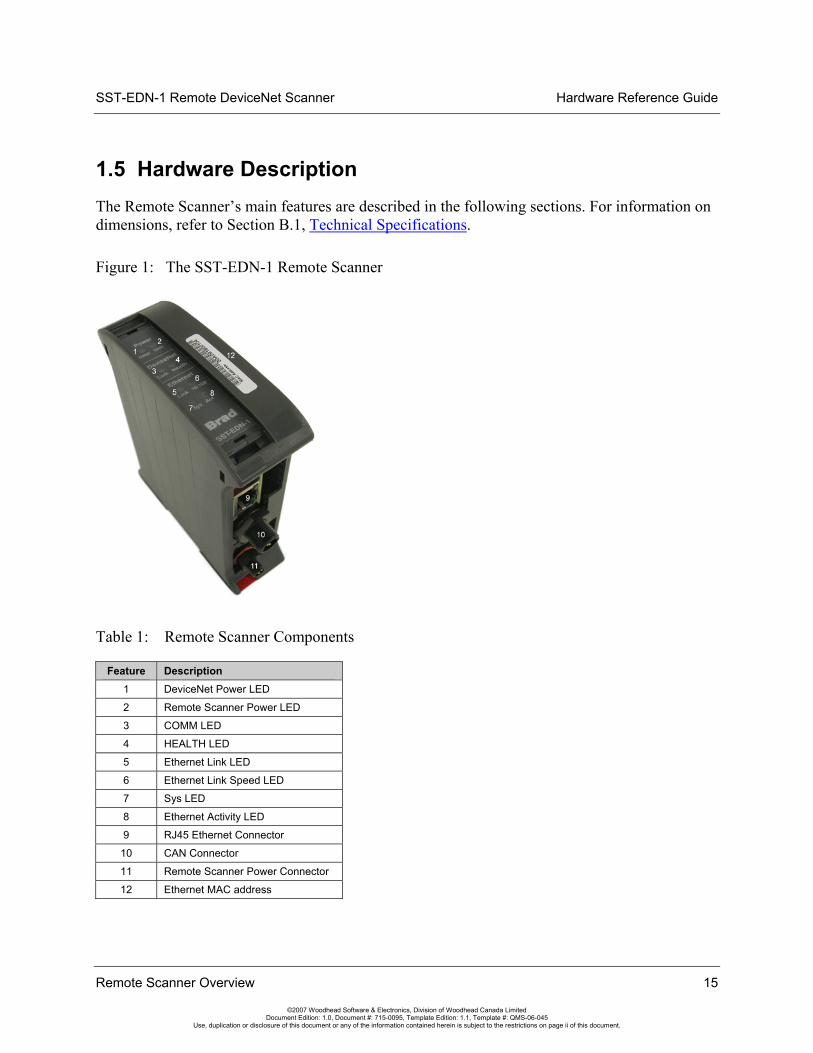
1.5 Hardware Description The Remote Scanner’s main features are described in the following sections. For information on dimensions, refer to Section B.1, Technical Specifications.
Figure 1: The SST-EDN-1 Remote Scanner
Table 1: Remote Scanner Components
Feature Description 1 DeviceNet Power LED
2 Remote Scanner Power LED
3 COMM LED
4 HEALTH LED
5 Ethernet Link LED
6 Ethernet Link Speed LED
7 Sys LED
8 Ethernet Activity LED
9 RJ45 Ethernet Connector
10 CAN Connector
11 Remote Scanner Power Connector
12 Ethernet MAC address

Hardware Reference Guide SST-EDN-1 Remote DeviceNet Scanner
16 Remote Scanner Overview
©2007 Woodhead Software & Electronics, Division of Woodhead Canada Limited Document Edition: 1.0, Document #: 715-0095, Template Edition: 1.1, Template #: QMS-06-045
Use, duplication or disclosure of this document or any of the information contained herein is subject to the restrictions on page ii of this document.
1.5.1 CAN Connector
The Male Micro (M12) CAN connector conforms to the standard DeviceNet pinout. Pin numbers and names are identified in the figure below.
Figure 2: CAN Connector
1.5.1.1 V+, V-
These terminals provide power to the isolated section of the network interface, and must be connected for the Remote Scanner to function. On DeviceNet networks, they connect directly to the “V+” and “V-” wires of the DeviceNet cable. On non-powered CAN networks, they must be connected to an external 11-24VDC supply.
1.5.1.2 CAN_H, CAN_L
These are the CAN communication bus signal terminals. Use only shielded twisted pair cable.
SST-EDN-1 Remote DeviceNet Scanner Hardware Reference Guide
Remote Scanner Overview 17
©2007 Woodhead Software & Electronics, Division of Woodhead Canada Limited Document Edition: 1.0, Document #: 715-0095, Template Edition: 1.1, Template #: QMS-06-045
Use, duplication or disclosure of this document or any of the information contained herein is subject to the restrictions on page ii of this document.
1.5.1.3 SHIELD
This is the shield connector. This terminal is “snubbed” to chassis ground via a 1M-ohm resistor.
Note According to the DeviceNet specification, the snubber circuit can be omitted if the Remote Scanner has no local connection to ground.
Note The shield should be connected directly to earth ground at only one point in the network. Refer to Section 2.4, Connecting Power, DeviceNet and Ethernet, for more information.
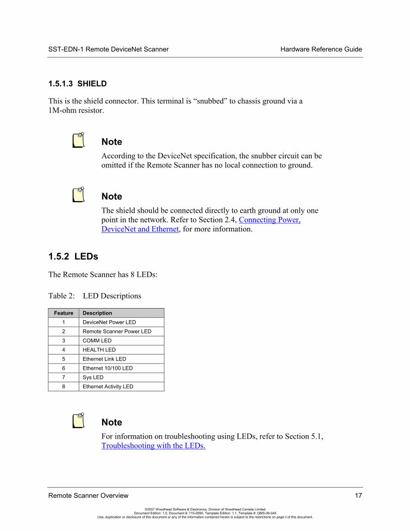
1.5.2 LEDs
The Remote Scanner has 8 LEDs:
Table 2: LED Descriptions
Feature Description 1 DeviceNet Power LED
2 Remote Scanner Power LED
3 COMM LED
4 HEALTH LED
5 Ethernet Link LED
6 Ethernet 10/100 LED
7 Sys LED
8 Ethernet Activity LED
Note For information on troubleshooting using LEDs, refer to Section 5.1, Troubleshooting with the LEDs.
Hardware Reference Guide SST-EDN-1 Remote DeviceNet Scanner
18 Remote Scanner Overview
©2007 Woodhead Software & Electronics, Division of Woodhead Canada Limited Document Edition: 1.0, Document #: 715-0095, Template Edition: 1.1, Template #: QMS-06-045
Use, duplication or disclosure of this document or any of the information contained herein is subject to the restrictions on page ii of this document.
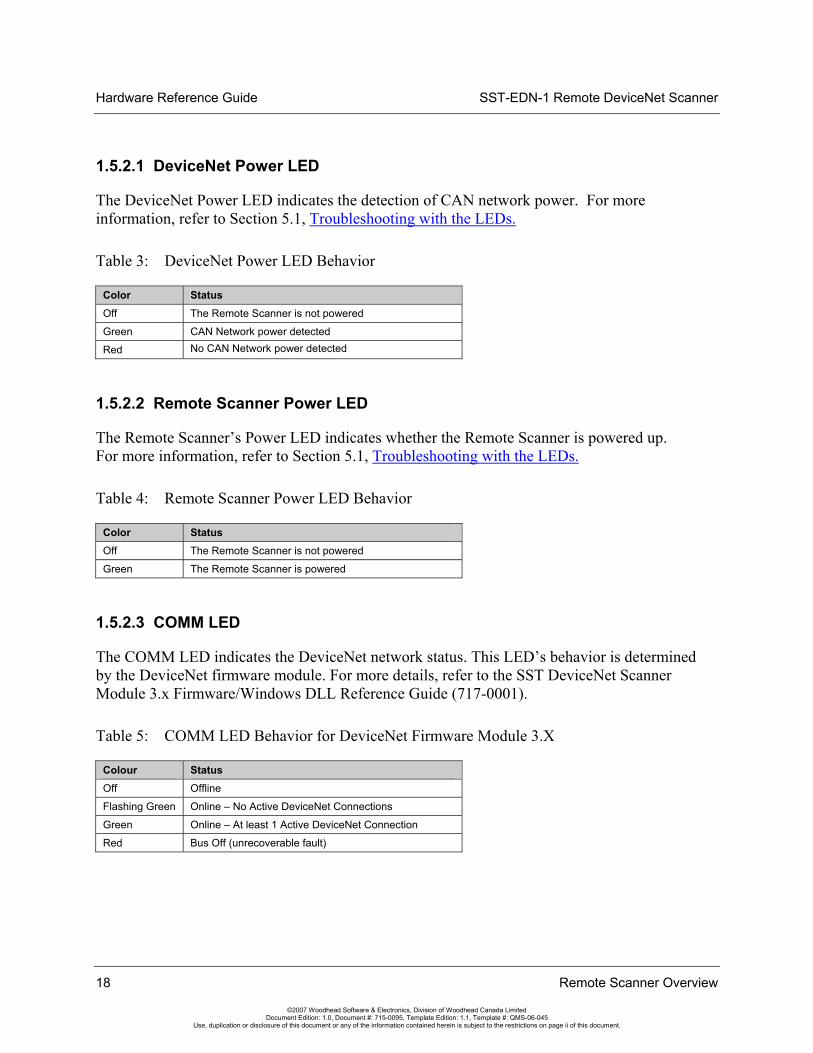
1.5.2.1 DeviceNet Power LED
The DeviceNet Power LED indicates the detection of CAN network power. For more information, refer to Section 5.1, Troubleshooting with the LEDs.
Table 3: DeviceNet Power LED Behavior
Color Status Off The Remote Scanner is not powered
Green CAN Network power detected
Red No CAN Network power detected
1.5.2.2 Remote Scanner Power LED
The Remote Scanner’s Power LED indicates whether the Remote Scanner is powered up. For more information, refer to Section 5.1, Troubleshooting with the LEDs.
Table 4: Remote Scanner Power LED Behavior
Color Status Off The Remote Scanner is not powered
Green The Remote Scanner is powered
1.5.2.3 COMM LED
The COMM LED indicates the DeviceNet network status. This LED’s behavior is determined by the DeviceNet firmware module. For more details, refer to the SST DeviceNet Scanner Module 3.x Firmware/Windows DLL Reference Guide (717-0001).
Table 5: COMM LED Behavior for DeviceNet Firmware Module 3.X
Colour Status Off Offline
Flashing Green Online – No Active DeviceNet Connections
Green Online – At least 1 Active DeviceNet Connection
Red Bus Off (unrecoverable fault)

SST-EDN-1 Remote DeviceNet Scanner Hardware Reference Guide
Remote Scanner Overview 19
©2007 Woodhead Software & Electronics, Division of Woodhead Canada Limited Document Edition: 1.0, Document #: 715-0095, Template Edition: 1.1, Template #: QMS-06-045
Use, duplication or disclosure of this document or any of the information contained herein is subject to the restrictions on page ii of this document.
1.5.2.4 HEALTH LED
The HEALTH LED indicates the channel’s health status. For more details, refer to Section 5.1, Troubleshooting with the LEDs.
Table 6: HEALTH LED Behavior
Color Status Off Firmware is not yet loaded to the Remote Scanner,
or the Remote Scanner is not powered
Green The firmware is loaded and running
Red An error occurred during the firmware load, or there is a firmware run-time error
1.5.2.5 Ethernet Link LED
The Ethernet Link LED indicates the Ethernet Link Status. For more details, refer to Section 5.1, Troubleshooting with the LEDs.
Table 7: Ethernet Link LED Behavior
Color Status Off No Ethernet Link established
Green Valid Ethernet Link established
1.5.2.6 Ethernet 10/100 LED
The Ethernet 10/100 LED indicates the Ethernet Link Speed. For more details refer to Section 5.1, Troubleshooting with the LEDs.
Table 8: Ethernet Link LED Behavior
Color Status Off No Ethernet Link established
Green Remote Scanner has auto-negotiated a 100Mbit/s Ethernet Link
Red Remote Scanner has auto-negotiated a 10Mbit/s Ethernet Link

Hardware Reference Guide SST-EDN-1 Remote DeviceNet Scanner
20 Remote Scanner Overview
©2007 Woodhead Software & Electronics, Division of Woodhead Canada Limited Document Edition: 1.0, Document #: 715-0095, Template Edition: 1.1, Template #: QMS-06-045
Use, duplication or disclosure of this document or any of the information contained herein is subject to the restrictions on page ii of this document.
1.5.2.7 Sys LED
The Sys LED indicates the overall health of the Remote Scanner. For more details, refer to Section 5.1, Troubleshooting with the LEDs.
Table 9: Ethernet Link LED Behavior
Color Status Off Remote Scanner operational
Red The Remote Scanner has encountered a fatal error
1.5.2.8 Ethernet Act LED
Table 10: Ethernet Act LED
Color Status Off No Ethernet activity
Green (solid or blinking)
Ethernet activity present

SST-EDN-1 Remote DeviceNet Scanner Hardware Reference Guide
Hardware Installation 21
©2007 Woodhead Software & Electronics, Division of Woodhead Canada Limited Document Edition: 1.0, Document #: 715-0095, Template Edition: 1.1, Template #: QMS-06-045
Use, duplication or disclosure of this document or any of the information contained herein is subject to the restrictions on page ii of this document.
2 Hardware Installation
Chapter Sections:
• System Requirements
• Handling Precautions
• Installing the Remote Scanner
• Connecting Power, DeviceNet, and Ethernet

Hardware Reference Guide SST-EDN-1 Remote DeviceNet Scanner
22 Hardware Installation
©2007 Woodhead Software & Electronics, Division of Woodhead Canada Limited Document Edition: 1.0, Document #: 715-0095, Template Edition: 1.1, Template #: QMS-06-045
Use, duplication or disclosure of this document or any of the information contained herein is subject to the restrictions on page ii of this document.
2.1 System Requirements Although the Remote Scanner may operate in systems that don’t meet the minimum requirements, extended data latencies may be observed. Using PC systems that don’t meet the minimum requirements is not recommended.
• PC with Microsoft Windows 2000 SP4 or XP SP2 or greater. Recommended 2GHz with 1G Ram or better.
• 10/100 MBit Ethernet port. Recommended 100MBit
2.2 Handling Precautions The Remote Scanner contains components that are sensitive to electrostatic discharge (ESD). Do not touch it without following these precautions:
Caution • Always follow correct ESD procedures before handling the card.
We strongly recommend the use of a grounding wrist strap.
• Never touch any of the Remote Scanner’s connectors or pins.
• When the Remote Scanner is not in use, always store it in its protective anti-static bag.

SST-EDN-1 Remote DeviceNet Scanner Hardware Reference Guide
Hardware Installation 23
©2007 Woodhead Software & Electronics, Division of Woodhead Canada Limited Document Edition: 1.0, Document #: 715-0095, Template Edition: 1.1, Template #: QMS-06-045
Use, duplication or disclosure of this document or any of the information contained herein is subject to the restrictions on page ii of this document.
2.3 Installing the Remote Scanner To install the Remote Scanner:
1. Unplug the power cord and any network cables.
2. Insert the upper part of the Remote Scanner onto the DIN rail.
Figure 3: Remote Scanner Insertion

Hardware Reference Guide SST-EDN-1 Remote DeviceNet Scanner
24 Hardware Installation
©2007 Woodhead Software & Electronics, Division of Woodhead Canada Limited Document Edition: 1.0, Document #: 715-0095, Template Edition: 1.1, Template #: QMS-06-045
Use, duplication or disclosure of this document or any of the information contained herein is subject to the restrictions on page ii of this document.
3. Press until the clip clicks onto the lower part of the DIN rail.
Figure 4: Remote Scanner Installed
4. Connect the power, DeviceNet, and Ethernet cables, as explained in the following
section.
Note For spacing and orientation requirements, see Appendix A.
SST-EDN-1 Remote DeviceNet Scanner Hardware Reference Guide
Hardware Installation 25
©2007 Woodhead Software & Electronics, Division of Woodhead Canada Limited Document Edition: 1.0, Document #: 715-0095, Template Edition: 1.1, Template #: QMS-06-045
Use, duplication or disclosure of this document or any of the information contained herein is subject to the restrictions on page ii of this document.
2.4 Connecting Power, DeviceNet and Ethernet
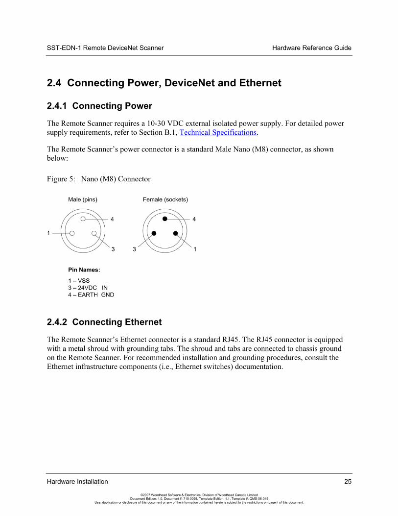
2.4.1 Connecting Power
The Remote Scanner requires a 10-30 VDC external isolated power supply. For detailed power supply requirements, refer to Section B.1, Technical Specifications.
The Remote Scanner’s power connector is a standard Male Nano (M8) connector, as shown below:
Figure 5: Nano (M8) Connector
2.4.2 Connecting Ethernet
The Remote Scanner’s Ethernet connector is a standard RJ45. The RJ45 connector is equipped with a metal shroud with grounding tabs. The shroud and tabs are connected to chassis ground on the Remote Scanner. For recommended installation and grounding procedures, consult the Ethernet infrastructure components (i.e., Ethernet switches) documentation.

Hardware Reference Guide SST-EDN-1 Remote DeviceNet Scanner
26 Hardware Installation
©2007 Woodhead Software & Electronics, Division of Woodhead Canada Limited Document Edition: 1.0, Document #: 715-0095, Template Edition: 1.1, Template #: QMS-06-045
Use, duplication or disclosure of this document or any of the information contained herein is subject to the restrictions on page ii of this document.
2.4.3 Connecting to a DeviceNet Network
The DeviceNet connector is a standard Male Micro (M12) CAN connector, as shown below:
Figure 6: CAN Connector
2.4.3.1 Termination
The Remote Scanner does not have a built-in termination resistor. Each network must have two termination resistors, one at each end of the trunk. Always refer to the DeviceNet Specification for proper network termination and wiring directions.
2.4.3.2 Power
Refer to http://www.odva.org for basic network guidelines, and to the DeviceNet Specification for proper powering directions.
2.4.3.3 Grounding
The network shield should be connected directly to earth ground at a single point in the network. Refer to http://www.odva.org for basic network guidelines, and to the DeviceNet Specification for proper grounding directions.

SST-EDN-1 Remote DeviceNet Scanner Hardware Reference Guide
Hardware Installation 27
©2007 Woodhead Software & Electronics, Division of Woodhead Canada Limited Document Edition: 1.0, Document #: 715-0095, Template Edition: 1.1, Template #: QMS-06-045
Use, duplication or disclosure of this document or any of the information contained herein is subject to the restrictions on page ii of this document.
2.4.4 Connecting to a CAN Network
2.4.4.1 Termination
The Remote Scanner does not have a built-in termination resistor. You must add termination in accordance with the requirements of the target CAN network.
2.4.4.2 Power
The CAN Network must supply 11-24 VDC power.
2.4.4.3 Grounding
For grounding directions, refer to the CAN network documentation.

Hardware Reference Guide SST-EDN-1 Remote DeviceNet Scanner
28 Hardware Installation
©2007 Woodhead Software & Electronics, Division of Woodhead Canada Limited Document Edition: 1.0, Document #: 715-0095, Template Edition: 1.1, Template #: QMS-06-045
Use, duplication or disclosure of this document or any of the information contained herein is subject to the restrictions on page ii of this document.

SST-EDN-1 Remote DeviceNet Scanner Hardware Reference Guide
Software Installation 29
©2007 Woodhead Software & Electronics, Division of Woodhead Canada Limited Document Edition: 1.0, Document #: 715-0095, Template Edition: 1.1, Template #: QMS-06-045
Use, duplication or disclosure of this document or any of the information contained herein is subject to the restrictions on page ii of this document.
3 Software Installation
Chapter Sections:
• Installing the Software and Drivers

Hardware Reference Guide SST-EDN-1 Remote DeviceNet Scanner
30 Software Installation
©2007 Woodhead Software & Electronics, Division of Woodhead Canada Limited Document Edition: 1.0, Document #: 715-0095, Template Edition: 1.1, Template #: QMS-06-045
Use, duplication or disclosure of this document or any of the information contained herein is subject to the restrictions on page ii of this document.
3.1 Installing the Software and Drivers Insert the DeviceNet Products installation CD shipped with the Remote Scanner and follow the on-screen instructions.
Note By default, the DeviceNet Remote Scanner feature will be checked. This feature is currently not supported on Windows Vista.
You can still install and use the Remote Scanner on Vista, but any applications that support it (e.g., the Console, the Remote Diagnostic Tool) must be run under administrator rights on Vista. You would therefore need to modify the application properties to set the privilege level to Run this program as an administrator.

SST-EDN-1 Remote DeviceNet Scanner Hardware Reference Guide
Configuration and Diagnostic Software 31
©2007 Woodhead Software & Electronics, Division of Woodhead Canada Limited Document Edition: 1.0, Document #: 715-0095, Template Edition: 1.1, Template #: QMS-06-045
Use, duplication or disclosure of this document or any of the information contained herein is subject to the restrictions on page ii of this document.
4 Configuration and Diagnostic Software
Chapter Sections:
• Overview of Card Names
Note The software and drivers must be installed before proceeding. For details, refer to Section 3.1, Installing the Software and Drivers.
Hardware Reference Guide SST-EDN-1 Remote DeviceNet Scanner
32 Configuration and Diagnostic Software
©2007 Woodhead Software & Electronics, Division of Woodhead Canada Limited Document Edition: 1.0, Document #: 715-0095, Template Edition: 1.1, Template #: QMS-06-045
Use, duplication or disclosure of this document or any of the information contained herein is subject to the restrictions on page ii of this document.
4.1 Overview of Card Names “Card Names” are used by applications when accessing Woodhead Software & Electronics DeviceNet Scanners. Each DeviceNet channel that exists in a system must be assigned a unique “Card Name”. For instance, if a PC system contains a DeviceNet PCI card and a Remote DeviceNet Scanner, a “Card Name” must be assigned to each. Applications can then address a particular DeviceNet module in the system. For more details on how “Card Names” are used by the Application, refer to the SST DeviceNet Scanner Module 3.x Firmware/DLL Reference Guide (717-0001).
Note Assigning Card Names to Local cards (e.g., PCI, PC104) will not be discussed in this manual. For details on those products, consult the relevant documentation.
4.1.1 Configuring Remote Scanner Card Names
For details on how to configure card names, refer to Section 3.1 of the Remote DeviceNet Diagnostic User Guide (717-0034).
SST-EDN-1 Remote DeviceNet Scanner Hardware Reference Guide
Troubleshooting 33
©2007 Woodhead Software & Electronics, Division of Woodhead Canada Limited Document Edition: 1.0, Document #: 715-0095, Template Edition: 1.1, Template #: QMS-06-045
Use, duplication or disclosure of this document or any of the information contained herein is subject to the restrictions on page ii of this document.
5 Troubleshooting
Chapter Sections:
• Troubleshooting with the LEDs
• Debugging with Firmware
• Debugging with the Diagnostic Tool
Warning Only qualified electrical personnel familiar with the construction and operation of this equipment and the hazards involved should install, adjust, operate, or service this equipment. Failure to observe this precaution could result in severe bodily injury or loss of life.
Hardware Reference Guide SST-EDN-1 Remote DeviceNet Scanner
34 Troubleshooting
©2007 Woodhead Software & Electronics, Division of Woodhead Canada Limited Document Edition: 1.0, Document #: 715-0095, Template Edition: 1.1, Template #: QMS-06-045
Use, duplication or disclosure of this document or any of the information contained herein is subject to the restrictions on page ii of this document.
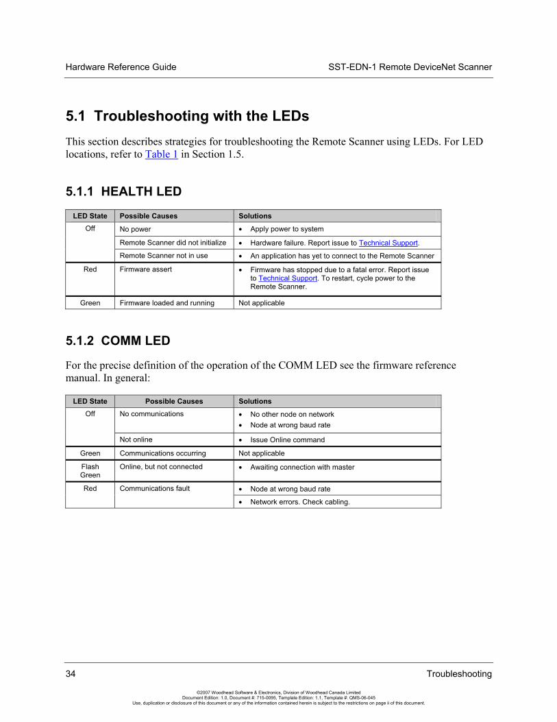
5.1 Troubleshooting with the LEDs This section describes strategies for troubleshooting the Remote Scanner using LEDs. For LED locations, refer to Table 1 in Section 1.5.
5.1.1 HEALTH LED
LED State Possible Causes Solutions
No power • Apply power to system
Remote Scanner did not initialize • Hardware failure. Report issue to Technical Support.
Off
Remote Scanner not in use • An application has yet to connect to the Remote Scanner
Red Firmware assert • Firmware has stopped due to a fatal error. Report issue to Technical Support. To restart, cycle power to the Remote Scanner.
Green Firmware loaded and running Not applicable
5.1.2 COMM LED
For the precise definition of the operation of the COMM LED see the firmware reference manual. In general:
LED State Possible Causes Solutions No communications • No other node on network
• Node at wrong baud rate Off
Not online • Issue Online command
Green Communications occurring Not applicable
Flash Green
Online, but not connected • Awaiting connection with master
• Node at wrong baud rate Red
Communications fault
• Network errors. Check cabling.

SST-EDN-1 Remote DeviceNet Scanner Hardware Reference Guide
Troubleshooting 35
©2007 Woodhead Software & Electronics, Division of Woodhead Canada Limited Document Edition: 1.0, Document #: 715-0095, Template Edition: 1.1, Template #: QMS-06-045
Use, duplication or disclosure of this document or any of the information contained herein is subject to the restrictions on page ii of this document.
5.1.3 DeviceNet Power LED
LED State Possible Causes Solutions Red No CAN network power • Check CAN Network power source
• Check CAN cabling
Green CAN network power applied Not applicable
Off The Remote Scanner is not powered up
• Power-up the Remote Scanner • Faulty board
5.1.4 Remote Scanner Power LED
LED State Possible Causes Solutions Green Remote Scanner power applied Not applicable
Off The Remote Scanner is not powered up
• Apply power to the Remote Scanner • Faulty board
5.1.5 Ethernet Link LED
LED State Possible Causes Solutions Green Remote Scanner has established
an Ethernet link Not applicable
Off No Ethernet link established • Ensure that the Remote Scanner is powered up • Ensure that the Remote Scanner is connected to a
powered Ethernet switch • Check Ethernet cabling
5.1.6 Ethernet 10/100 LED
LED State Possible Causes Solutions Green Remote Scanner has auto-
negotiated a 100Mbit/s Ethernet link
Not applicable
Red Remote Scanner has auto-negotiated a 10Mbit/s Ethernet link
Not applicable
Off No Ethernet link established • Ensure that the Remote Scanner is powered up • Ensure that the Remote Scanner is connected to a
powered Ethernet switch
• Check Ethernet cabling

Hardware Reference Guide SST-EDN-1 Remote DeviceNet Scanner
36 Troubleshooting
©2007 Woodhead Software & Electronics, Division of Woodhead Canada Limited Document Edition: 1.0, Document #: 715-0095, Template Edition: 1.1, Template #: QMS-06-045
Use, duplication or disclosure of this document or any of the information contained herein is subject to the restrictions on page ii of this document.
5.1.7 Ethernet Act LED
LED State Possible Causes Solutions Off No Ethernet activity Not applicable
Green (solid or blinking)
Ethernet activity present Not applicable
5.1.8 Remote Scanner Sys LED
LED State Possible Causes Solutions Off No fatal errors present Not applicable
Red The Remote Scanner has encountered a fatal error
• Contact Technical Support
5.2 Debugging with Firmware Once firmware has been loaded, every SST DeviceNet firmware module has a common header. This can be retrieved via the Windows32 API call, “GetModuleHeader()”. Below is an example of the AMH for the Remote Scanner firmware module. For more information, consult the Firmware Reference Guide.
Table 11: Application Module Header
Offset Name Data Type Description
0000h ModuleType CHAR[2] "DN" (444eh) = card OK "ER" (4552h) = fatal error
0002h Reserved UINT2 0000h
0004h CardId UINT2 For host application use
0006h Kernel ID UINT2 0003h (CAN 2.0 A/B Kernel)
0008h Kernel Rev UINT2 Depends on the version used by firmware
000ah ModuleId UINT2 Module Id, 0x14 = DNSCAN
000ch ModuleRev UINT2 Module revision
000eh NetSerial UINT4 DeviceNet serial number
0012h CardType CHAR[16] Card type (i.e., "SST-EDN")
0022h CardSerial CHAR[8] Card serial number
002ah IrqControl UINT2 Card interrupt control
002ch IrqStatusA UINT1 Card interrupt status A
002dh IrqStatusB UINT1 Card interrupt status B
002eh MainCode UINT2 Main Application Error Code

SST-EDN-1 Remote DeviceNet Scanner Hardware Reference Guide
Troubleshooting 37
©2007 Woodhead Software & Electronics, Division of Woodhead Canada Limited Document Edition: 1.0, Document #: 715-0095, Template Edition: 1.1, Template #: QMS-06-045
Use, duplication or disclosure of this document or any of the information contained herein is subject to the restrictions on page ii of this document.
Offset Name Data Type Description
0030h CanStatus UINT2 CAN status word
0032h CanTx UINT2 CAN transmit counter. Incremented when messages are submitted to the CAN controller.
0034h CanAck UINT2 CANAck error counter. Incremented when a transmit message is aborted due to lack of acknowledgment from other stations. When CanAck is incremented, CanTx is decremented to compensate for messages not actually transmitted.
0036h CanRx UINT2 CAN receive counter. Incremented when messages are received. Messages that fail the receive filter still increment CanRx.
0038h CanError UINT2 CAN communication error counter. Incremented when a CAN frame error is detected.
003ah CanLost UINT2 CAN lost messages counter. Incremented when a CAN message is received before the previous one is queued.
003ch CanOverrun UINT2 CAN receive queue overrun counter. Incremented when a CAN message is lost due to a full receive queue.
003eh AddCode UINT2 Additional Application Error Code
0040h Message CHAR[60] When ModuleType is "DN", contains the module identification string. When ModuleType is "ER”, contains the kernel error string.
007Ch Major Tick Interval UINT2 0005h (ms per tick)
007Eh Minor Tick Interval UINT2 1388 (number of minor ticks per major tick)
5.3 Debugging with the Diagnostic Tool For details on debugging software with the Diagnostic Tool, refer to Section 3.6 in the Remote DeviceNet Diagnostic User Guide (717-0034).

Hardware Reference Guide SST-EDN-1 Remote DeviceNet Scanner
38 Troubleshooting
©2007 Woodhead Software & Electronics, Division of Woodhead Canada Limited Document Edition: 1.0, Document #: 715-0095, Template Edition: 1.1, Template #: QMS-06-045
Use, duplication or disclosure of this document or any of the information contained herein is subject to the restrictions on page ii of this document.
SST-EDN-1 Remote DeviceNet Scanner Hardware Reference Guide
Spacing Requirements 39
©2007 Woodhead Software & Electronics, Division of Woodhead Canada Limited Document Edition: 1.0, Document #: 715-0095, Template Edition: 1.1, Template #: QMS-06-045
Use, duplication or disclosure of this document or any of the information contained herein is subject to the restrictions on page ii of this document.
A Spacing Requirements
Appendix Sections:
• Vertical Mounting
• Horizontal Mounting

Hardware Reference Guide SST-EDN-1 Remote DeviceNet Scanner
40 Spacing Requirements
©2007 Woodhead Software & Electronics, Division of Woodhead Canada Limited Document Edition: 1.0, Document #: 715-0095, Template Edition: 1.1, Template #: QMS-06-045
Use, duplication or disclosure of this document or any of the information contained herein is subject to the restrictions on page ii of this document.
A.1 Vertical Mounting When mounted vertically (connectors facing down), Remote Scanners can have zero space between each other on the DIN rail.
Figure 7: Remote Scanners, Mounted Vertically
In this orientation, the Remote Scanners are rated to operate up to 50 degrees Celsius ambient in a restricted-air-flow environment. “Restricted air flow environment” is defined as an environment without forced air movement, such as a cabinet without fans.
SST-EDN-1 Remote DeviceNet Scanner Hardware Reference Guide
Spacing Requirements 41
©2007 Woodhead Software & Electronics, Division of Woodhead Canada Limited Document Edition: 1.0, Document #: 715-0095, Template Edition: 1.1, Template #: QMS-06-045
Use, duplication or disclosure of this document or any of the information contained herein is subject to the restrictions on page ii of this document.
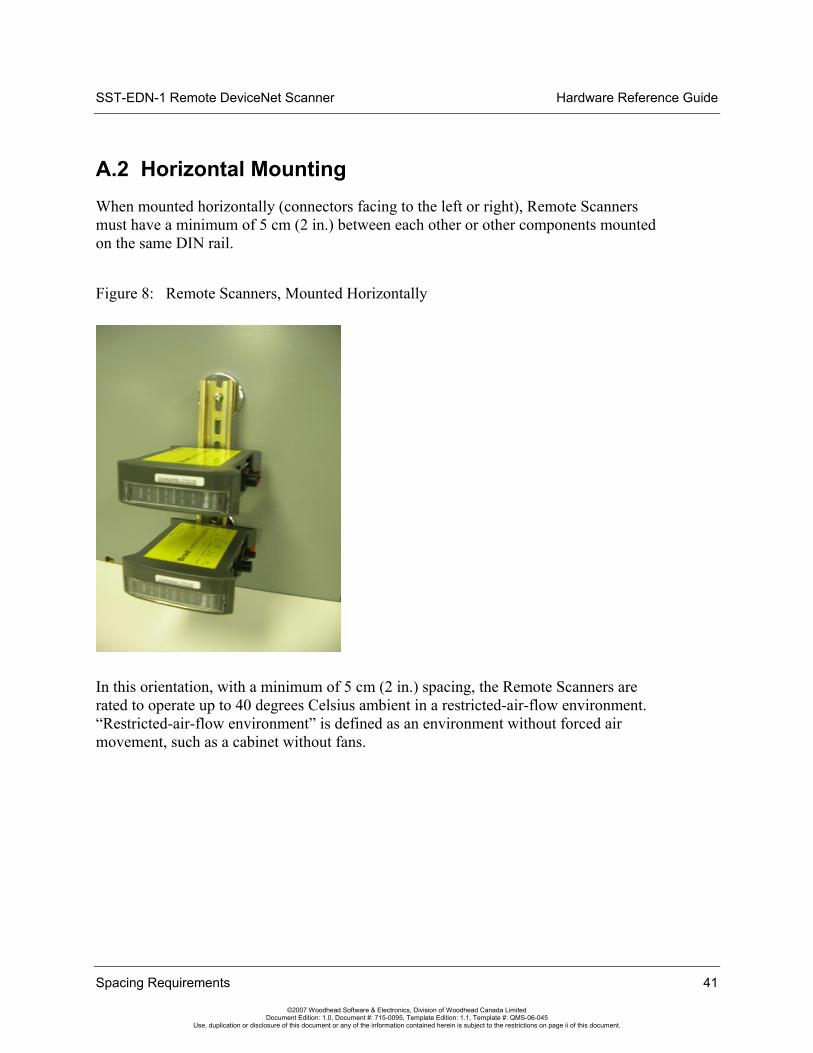
A.2 Horizontal Mounting When mounted horizontally (connectors facing to the left or right), Remote Scanners must have a minimum of 5 cm (2 in.) between each other or other components mounted on the same DIN rail.
Figure 8: Remote Scanners, Mounted Horizontally
In this orientation, with a minimum of 5 cm (2 in.) spacing, the Remote Scanners are rated to operate up to 40 degrees Celsius ambient in a restricted-air-flow environment. “Restricted-air-flow environment” is defined as an environment without forced air movement, such as a cabinet without fans.
Hardware Reference Guide SST-EDN-1 Remote DeviceNet Scanner
42 Spacing Requirements
©2007 Woodhead Software & Electronics, Division of Woodhead Canada Limited Document Edition: 1.0, Document #: 715-0095, Template Edition: 1.1, Template #: QMS-06-045
Use, duplication or disclosure of this document or any of the information contained herein is subject to the restrictions on page ii of this document.

SST-EDN-1 Remote DeviceNet Scanner Hardware Reference Guide
Technical Specifications 43
©2007 Woodhead Software & Electronics, Division of Woodhead Canada Limited Document Edition: 1.0, Document #: 715-0095, Template Edition: 1.1, Template #: QMS-06-045
Use, duplication or disclosure of this document or any of the information contained herein is subject to the restrictions on page ii of this document.
B Technical Specifications
Appendix Sections:
• Technical Specifications

Hardware Reference Guide SST-EDN-1 Remote DeviceNet Scanner
44 Technical Specifications
©2007 Woodhead Software & Electronics, Division of Woodhead Canada Limited Document Edition: 1.0, Document #: 715-0095, Template Edition: 1.1, Template #: QMS-06-045
Use, duplication or disclosure of this document or any of the information contained herein is subject to the restrictions on page ii of this document.
B.1 Technical Specifications The following tables list the technical specifications for the Remote Scanner.
Table 12: Environmental Specifications
Ambient Conditions Storage temp: -40°C to +85°C
Operating temp: 0°C to 50°C Vertical Mount. For details, refer to Section A.1.
0°C to 40°C Horizontal Mount. For details, refer to Section A.2.
Humidity: 5% to 95% non-condensing
Table 13: Network Specifications - CAN
Cable Shielded twisted pair, compatible with target network
Connector Male Micro (M12)
External Power 11-24 VDC, 50mA (typical)
Isolation 500V
Protocol CAN 2.0 A/B
Data Rate Up to 1 Mbaud for CAN 125K, 250K and 500K baud for DeviceNet
Table 14: Network Specifications - Ethernet
Cable Recommended Cat 5e Shielded
Connector RJ45
Data Rate 10/100 MBit/s – auto-negotiate
Table 15: Remote Scanner Power
Connector Male Nano (M8)
External Power Supply Requirements
Isolated 10-30 VDC 0.33A @ 24 volts (typical - per Remote Scanner) 2 Amps @ 24 volts (peak startup inrush current - per Remote Scanner)
Cable Length Requirements
Maximum 3 Meters

SST-EDN-1 Remote DeviceNet Scanner Hardware Reference Guide
CE Compliance 45
©2007 Woodhead Software & Electronics, Division of Woodhead Canada Limited Document Edition: 1.0, Document #: 715-0095, Template Edition: 1.1, Template #: QMS-06-045
Use, duplication or disclosure of this document or any of the information contained herein is subject to the restrictions on page ii of this document.
C CE Compliance
Appendix Sections:
• CE Compliance Statement
Hardware Reference Guide SST-EDN-1 Remote DeviceNet Scanner
46 CE Compliance
©2007 Woodhead Software & Electronics, Division of Woodhead Canada Limited Document Edition: 1.0, Document #: 715-0095, Template Edition: 1.1, Template #: QMS-06-045
Use, duplication or disclosure of this document or any of the information contained herein is subject to the restrictions on page ii of this document.
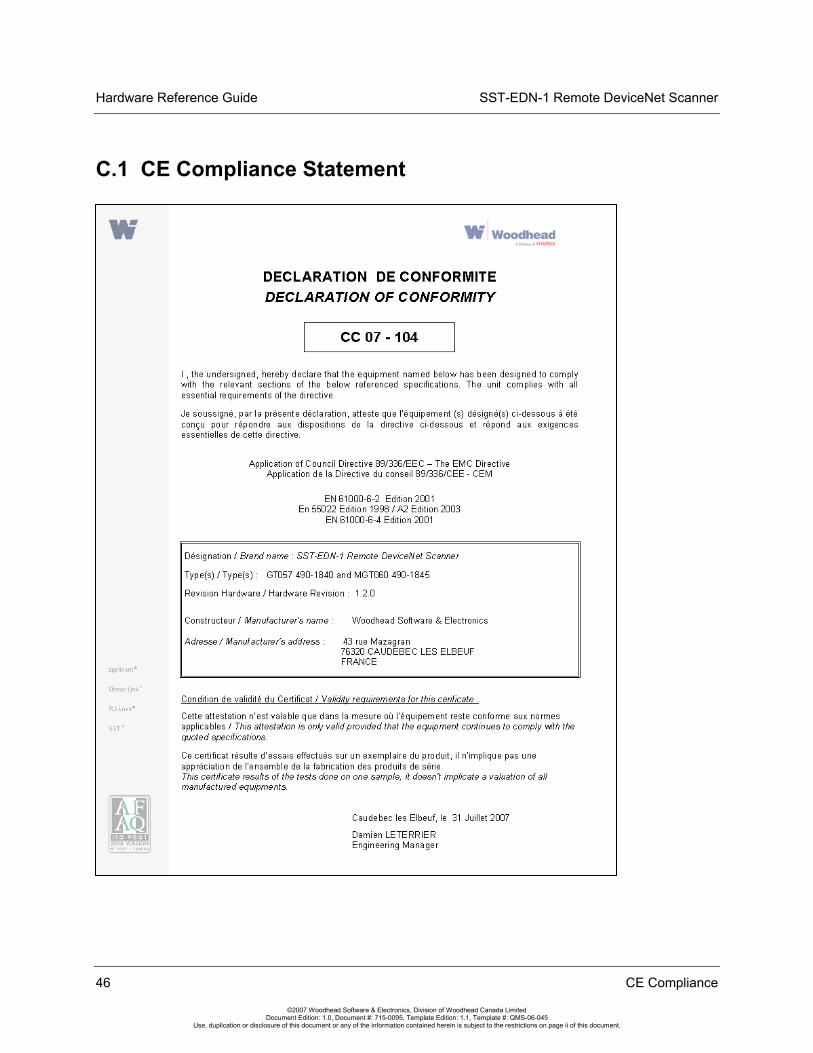
C.1 CE Compliance Statement

SST-EDN-1 Remote DeviceNet Scanner Hardware Reference Guide
Warranty and Support 47
©2007 Woodhead Software & Electronics, Division of Woodhead Canada Limited Document Edition: 1.0, Document #: 715-0095, Template Edition: 1.1, Template #: QMS-06-045
Use, duplication or disclosure of this document or any of the information contained herein is subject to the restrictions on page ii of this document.
D Warranty and Support
Appendix Sections:
• Warranty
• Reference Documents
• Technical Support

Hardware Reference Guide SST-EDN-1 Remote DeviceNet Scanner
48 Warranty and Support
©2007 Woodhead Software & Electronics, Division of Woodhead Canada Limited Document Edition: 1.0, Document #: 715-0095, Template Edition: 1.1, Template #: QMS-06-045
Use, duplication or disclosure of this document or any of the information contained herein is subject to the restrictions on page ii of this document.
D.1 Warranty For warranty information, refer to: http://www.mysst.com/warranty.asp.
D.2 Reference Documents • DeviceNet Specification
• CIP Networks Library, Volume I, “Common Industrial Protocol”, Edition 2.2
• CIP Networks Library, Volume III, “DeviceNet Adaptation of CIP”, Edition 1.1
D.3 Technical Support Please ensure that you have the following information readily available before calling for technical support:
• Card model, type and serial number
• Computer’s make, model, CPU speed and hardware configuration (other cards installed)
• Operating system type and version
• Details of the problem you are experiencing: firmware module type and version, target network, and circumstances that may have caused the problem

SST-EDN-1 Remote DeviceNet Scanner Hardware Reference Guide
Warranty and Support 49
©2007 Woodhead Software & Electronics, Division of Woodhead Canada Limited Document Edition: 1.0, Document #: 715-0095, Template Edition: 1.1, Template #: QMS-06-045
Use, duplication or disclosure of this document or any of the information contained herein is subject to the restrictions on page ii of this document.
D.3.1 Getting Help
Technical support is available during regular business hours by telephone, fax or email from any Woodhead Software & Electronics office, or from http://www.woodhead.com. Documentation and software updates are also available on the website.
Note If you are using the Remote Scanner with a third-party application, refer to the documentation for that package for information on configuring the software for the card.
North America
Canada: Tel: 1-519-725-5136 Fax: 1-519-725-1515 Email: [email protected]
Europe
France: Tel: 33-(0)2-32-96-04-22 Fax: 33-(0)2-32-96-04-21 Email: [email protected]
Germany: Tel: 49-711-782-374-22 Fax: 49-711-782-374-11 Email: [email protected]
Italy: Tel: 39-010-595-4052 Fax: 39-010-595-6925 Email: [email protected]

Hardware Reference Guide SST-EDN-1 Remote DeviceNet Scanner
50 Warranty and Support
©2007 Woodhead Software & Electronics, Division of Woodhead Canada Limited Document Edition: 1.0, Document #: 715-0095, Template Edition: 1.1, Template #: QMS-06-045
Use, duplication or disclosure of this document or any of the information contained herein is subject to the restrictions on page ii of this document.
Other countries: Tel: 33-(0)2-32-96-04-23 Fax: 33-(0)2-32-96-04-21 Email: [email protected]
Asia-Pacific
Japan: Tel: 81-3-5791-4621 Fax: 81-3-5791-4688 Email: [email protected]
Singapore: Tel: 65-6261-6533 Fax: 65-6261-3588 Email: [email protected]
China: Tel: 86-21-5835-9885 Fax: 86-21-5835-9980 Email: [email protected]
For the most current contact details, please visit http://www.woodhead.com.
SST-EDN-1 Remote DeviceNet Scanner Hardware Reference Guide
Index 51
©2007 Woodhead Software & Electronics, Division of Woodhead Canada Limited Document Edition: 1.0, Document #: 715-0095, Template Edition: 1.1, Template #: QMS-06-045
Use, duplication or disclosure of this document or any of the information contained herein is subject to the restrictions on page ii of this document.
Index
A application module header, 36
B baud rate
for CAN network, 44 for Ethernet, 44
byte ordering, 13
C cable
for CAN network, 44 for Ethernet, 44
cable length requirements, 44 CAN connector, 16 CAN network
cable for, 44 connecting to, 27 data rate for, 44 grounding for, 27 power for, 27 protocol for, 44
Card Names configuring, 32 described, 32
cautions defined, ix electrostatic discharge, 12, 22
CE Compliance, 46 channel, defined, viii COMM LED
described, 18 troubleshooting with, 34
conventions used in this guide special notation, ix special terms, viii style, vii
D data rate, 44 debugging
with firmware, 36 with the Diagnostic Tool, 37
DeviceNet network connecting to, 26 grounding for, 26 termination for, 26
DeviceNet Power LED described, 18 troubleshooting with, 35
Diagnostic Tool, debugging with, 37

Hardware Reference Guide SST-EDN-1 Remote DeviceNet Scanner
52 Index
©2007 Woodhead Software & Electronics, Division of Woodhead Canada Limited Document Edition: 1.0, Document #: 715-0095, Template Edition: 1.1, Template #: QMS-06-045
Use, duplication or disclosure of this document or any of the information contained herein is subject to the restrictions on page ii of this document.
drivers, installing, 30 DWORD, defined, viii
E electrostatic discharge (ESD), 12, 22 emergency stop circuit, 12 Ethernet
connecting, 25 data rate of, 44
Ethernet 10/100 LED described, 19 troubleshooting with, 35
Ethernet Act LED described, 20 troubleshooting with, 36
Ethernet Connector, 15 Ethernet Link LED
described, 19 troubleshooting with, 35
external power for CAN network, 44 for Remote Scanner, 44
F features of Remote Scanner, 13 firmware module header, 36 firmware module, defined, viii firmware, debugging with, 36
G grounding
for CAN network, 27 for DeviceNet network, 26
grounding wrist strap, 22
H hardware
CAN connector, 16 diagram of, 15 LEDs, 17
HLTH LED described, 19 troubleshooting with, 34
horizontal mounting, 41 host, defined, viii humidity, 44
I installing software and drivers, 30 installing the Remote Scanner, 23 installing under Windows Vista, 30 isolation, CAN network, 44
L LEDs
described, 17 troubleshooting with, 34
M M12 CAN connector, 16 mounting horizontally, 41 mounting vertically, 40
N network
CAN specifications for, 44 connecting to CAN, 27 connecting to DeviceNet, 26 Ethernet specifications for, 44 termination for, 26, 27
note, defined, ix
O
operating temperature, 44
P power
connecting, 25 external, 44 for CAN network, 27, 44 for DeviceNet network, 26

SST-EDN-1 Remote DeviceNet Scanner Hardware Reference Guide
Index 53
©2007 Woodhead Software & Electronics, Division of Woodhead Canada Limited Document Edition: 1.0, Document #: 715-0095, Template Edition: 1.1, Template #: QMS-06-045
Use, duplication or disclosure of this document or any of the information contained herein is subject to the restrictions on page ii of this document.
Power LED for DeviceNet, 18 for Remote Scanner, 18 troubleshooting with, 35
power, for Remote Scanner, 44 precautions
electrostatic discharge, 12, 22 emergency stop circuit, 12 handling Remote Scanner, 12 installation, 33
protocol, for CAN network, 44 purpose of this guide, vi
R reference documents, 48 Remote Scanner
byte ordering and, 13 capabilities of, 13 cautions for, 12, 22 CE compliance and, 46 configuring card names for, 32 connecting to a network, 25 debugging, 36 defined, viii hardware, 15 installing, 23 installing software and drivers on, 30 mounting, 40, 41 PC requirements for, 14 spacing requirements for, 40 system requirements for, 22 technical specifications for, 44 technical support for, 48 troubleshooting, 34 viewing status of, 17 warnings for, 12, 33 warranty for, 48
requirements, PC, 14 requirements, system, 22 RJ45 Ethernet Connector, 15
S Scanner. See Remote Scanner shield connector, 17 software, installing, 30 SST-EDN-1. See Remote Scanner status, of Remote Scanner, 17 storage temperature, of Remote Scanner, 44 support, 48 Sys LED
described, 20 troubleshooting with, 36
system requirements, for Remote Scanner, 22
T technical specifications, 44 Technical Support, 48 temperature
operating, 44 storage, 44
termination for CAN network, 27 for DeviceNet network, 26
troubleshooting, with LEDs, 34
U using this guide, vi
V
vertical mounting, 40 Vista, installing under, 30
W warnings
defined, ix emergency stop circuit, 12 installation, 33 Remote Scanner handling, 12

Hardware Reference Guide SST-EDN-1 Remote DeviceNet Scanner
54 Index
©2007 Woodhead Software & Electronics, Division of Woodhead Canada Limited Document Edition: 1.0, Document #: 715-0095, Template Edition: 1.1, Template #: QMS-06-045
Use, duplication or disclosure of this document or any of the information contained herein is subject to the restrictions on page ii of this document.
warranty, 48 Windows Vista, installing under, 30
WORD, defined, viii wrist strap, 22