Embed Size (px)
Citation preview
SST & SRS DAY TANK MANUALDecember 2010
Simplex, Inc., 5300 Rising Moon Road, Springfi eld, IL 62711-6228 • 217-483-1600 • Fax 217-483-1616© 2010 Simplex, Inc. All Rights Reserved. • Printed in the USA. • www.simplexdirect.com
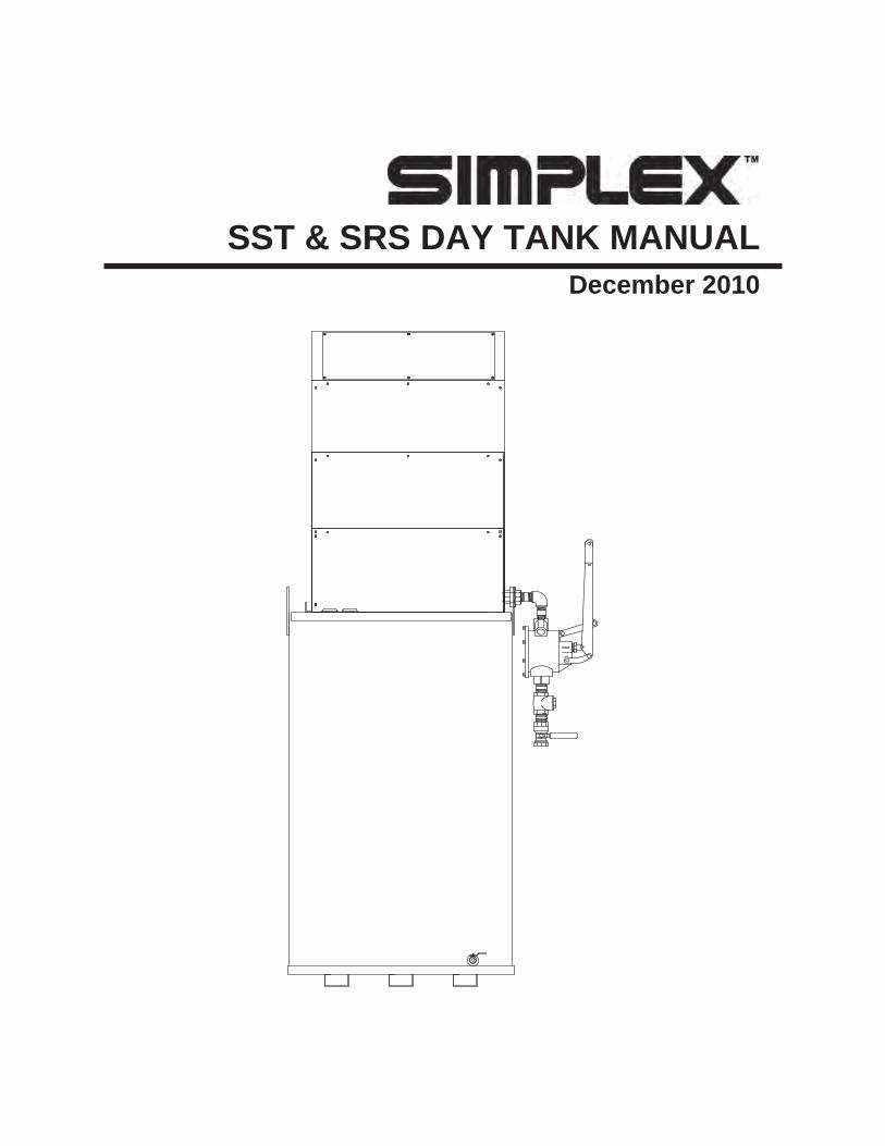
Day Tank Identifi cation & Warranty Information
Attention Simplex Day Tank end user. This Day Tank Identifi cation Form and the en-closed Day Tank Registration Card serves as your warranty registration. Please fi ll out the enclosed registration card completely and mail it to Simplex Inc.
Simplex Day Tank Weld Tag Serial Number:
Simplex Work Order Number: U.L. Number:
Date Purchased:
Date Shipped/Warranty Commencement:
Day Tank Sold To:
Customer Identifi cation Number:
SPECIFICATIONS:
Day Tank Model/Size:
Day Tank Pump/Motor Size:
Day Tank Options:
Simplex, Inc., 5300 Rising Moon Road, Springfi eld, IL 62711-6228 • 217-483-1600 • Fax 217-483-1616© 2010 Simplex, Inc. All Rights Reserved. • Printed in the USA. • www.simplexdirect.com
SST & SRS DAY TANK MANUAL • page 1 of 25
Contents
INSTALLATION ............................................................................ 2Vent Openings ........................................................................ 5Siphon-Drain .......................................................................... 7Day Tank Pump Priming Procedure (Required) .................. 8
DAY TANK OPERATION .............................................................. 9Automatic Operation ........................................................... 10High Level Fill Disabled ....................................................... 11Fill Test Pushbutton ............................................................ 11Low Level Alarm .................................................................. 12Manual Operation ................................................................. 12Remote Operation ................................................................ 12Lamp Test ............................................................................. 12Automatic Duplex Pump Controller, Option 345 ............... 13Overfl ow-Return Tank, Option 383 ..................................... 14Overfl ow-Return Pump And Controller Added To Day Tank, Option 390 ..................................... 15
MAINTENANCE .......................................................................... 16Each Year .............................................................................. 16After The First 3 Years ......................................................... 16
TROUBLESHOOTING ................................................................ 17No Fuel Delivered ................................................................. 17Insuffi cient Fuel Delivered .................................................. 17Rapid Pump Wear ................................................................ 17Pump Delivers for Short Period and Quits ........................ 17Pump Requires Too Much Power ....................................... 17Noisy Operation ................................................................... 17Pump Requires Frequent Re-priming ................................ 17Motor Does Not Turn or Turns Intermittently .................... 18Pump Leaks Fuel ................................................................. 18
DRAWINGS AND PARTS LIST .................................................. 18
APPENDIX A - ABBREVIATIONS USED IN THIS MANUAL ..... 19
APPENDIX B - TECHNICAL DATA ............................................ 20
The information herein is the property of Simplex, Inc. and/or its subsidiaries.Without written permission, any copying, transmitting to others, and other use
except that for which it is loaned, is prohibited.
Simplex, Inc., 5300 Rising Moon Road, Springfi eld, IL 62711-6228 • 217-483-1600 • Fax 217-483-1616© 2010 Simplex, Inc. All Rights Reserved. • Printed in the USA. • www.simplexdirect.com
SST & SRS DAY TANK MANUAL • page 2 of 25
INSTALLATION
Location of the Day Tank is of prime importance and should be done by trained personnel. It is one of the most critical factors involved in reliable and safe operation. The Day Tank must be positioned and installed according to the main fuel storage tank and engine location. In general locate the Day Tank as close to the engine as possible con-sistent with applicable local and national plumbing and electrical codes. Always position the Day Tank so that the highest fuel level in the tank is lower than the engine injectors. The Day Tank must be located not farther than 200' from the main fuel tank. The Day Tank must not be more than 18' higher than the lowest fuel level in the main fuel tank. Never locate the Day Tank in a confi ned space without consideration for accidental fuel spillage and use a rupture basin when necessary. Never locate the Day Tank near a surface or object which may be adversely affected by fuel oil. Never locate a Day Tank system above a residential living space.
IMPORTANT NOTE!! The system shall be for use with fuel oil as described by NFPA321, “Basic Classifi cation of Flammable and Com-bustible Liquids.” As defi ned by this standard, the fuel supply system shall be for use with “combustible liquids,” those having a fl ash point at or above 100°F and further defi ned as Class II or Class III liquids. In no case shall a liquid having a fl ash point less than 100°F be used. In every case, the system shall not be used or applied at a temperature in excess of the fl ash point of the contents. Electrical equipment used in the system shall be in accordance with NFPA30, section 5-7, wherein it states “For areas where Class II or Class III liquids only are stored or handled at a temperature below their fl ash points, the electrical equipment may be installed in accordance with provisions of NFPA70, National Electrical Code, for ordinary locations...”
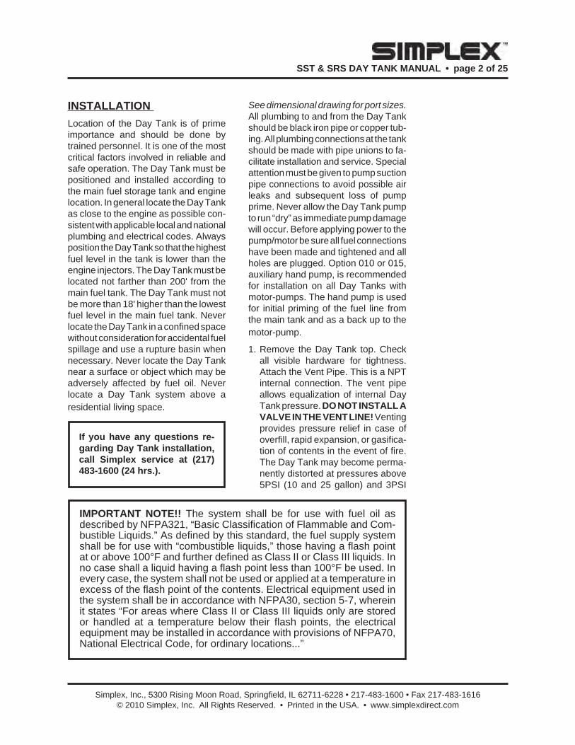
See dimensional drawing for port sizes. All plumbing to and from the Day Tank should be black iron pipe or copper tub-ing. All plumbing connections at the tank should be made with pipe unions to fa-cilitate installation and service. Special attention must be given to pump suction pipe connections to avoid possible air leaks and subsequent loss of pump prime. Never allow the Day Tank pump to run “dry” as immediate pump damage will occur. Before applying power to the pump/motor be sure all fuel connections have been made and tightened and all holes are plugged. Option 010 or 015, auxiliary hand pump, is recommended for installation on all Day Tanks with motor-pumps. The hand pump is used for initial priming of the fuel line from the main tank and as a back up to the motor-pump.
1. Remove the Day Tank top. Check all visible hardware for tightness. Attach the Vent Pipe. This is a NPT internal connection. The vent pipe allows equalization of internal Day Tank pressure. DO NOT INSTALL A VALVE IN THE VENT LINE! Venting provides pressure relief in case of overfi ll, rapid expansion, or gasifi ca-tion of contents in the event of fi re. The Day Tank may become perma-nently distorted at pressures above 5PSI (10 and 25 gallon) and 3PSI
If you have any questions re-garding Day Tank installation, call Simplex service at (217) 483-1600 (24 hrs.).
Simplex, Inc., 5300 Rising Moon Road, Springfi eld, IL 62711-6228 • 217-483-1600 • Fax 217-483-1616© 2010 Simplex, Inc. All Rights Reserved. • Printed in the USA. • www.simplexdirect.com
SST & SRS DAY TANK MANUAL • page 3 of 25
(50–400 gallon) and may rupture at pressures above the maximum with-stand pressure of 25PSI (10 and 25 gallon) and 15PSI (50–400 gallon). Day Tank operation without a vent pipe is strictly not recommended. The vent pipe should be at least 5 feet higher than any other pipe and should terminate outdoors. The vent pipe must not extend or terminate more than 12' above the Day Tank. There should be no low portions or sags in the vent pipe which can trap liquid. The end of the pipe should be fi tted with a 180° weather protected vent cap to shed water and should be screened to keep out pests, leaves, etc.
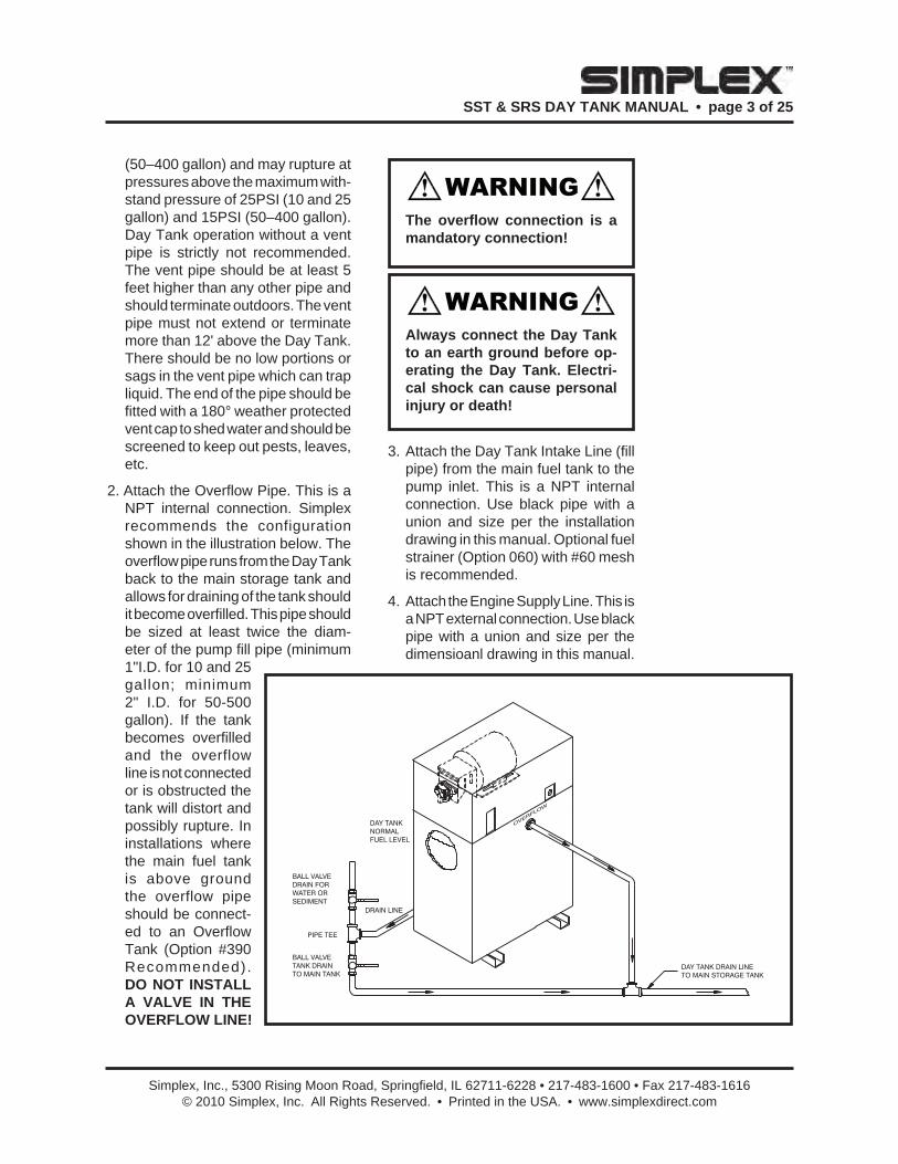
2. Attach the Overfl ow Pipe. This is a NPT internal connection. Simplex recommends the configuration shown in the illustration below. The overfl ow pipe runs from the Day Tank back to the main storage tank and allows for draining of the tank should it become overfi lled. This pipe should be sized at least twice the diam-eter of the pump fi ll pipe (minimum 1"I.D. for 10 and 25 gallon; minimum 2" I.D. for 50-500 gallon). If the tank becomes overfi lled and the overflow line is not connected or is obstructed the tank will distort and possibly rupture. In installations where the main fuel tank is above ground the overflow pipe should be connect-ed to an Overfl ow Tank (Option #390 Recommended). DO NOT INSTALL A VALVE IN THE OVERFLOW LINE!
The overfl ow connection is a mandatory connection!
DAY TANK
NORMAL
FUEL LEVEL
DAY TANK DRAIN LINE
TO MAIN STORAGE TANK
OVE
RFLO
W
BALL VALVE
DRAIN FOR
WATER OR
SEDIMENT
PIPE TEE
DRAIN LINE
BALL VALVE
TANK DRAIN
TO MAIN TANK
3. Attach the Day Tank Intake Line (fi ll pipe) from the main fuel tank to the pump inlet. This is a NPT internal connection. Use black pipe with a union and size per the installation drawing in this manual. Optional fuel strainer (Option 060) with #60 mesh is recommended.
4. Attach the Engine Supply Line. This is a NPT external connection. Use black pipe with a union and size per the dimensioanl drawing in this manual.
Always connect the Day Tank to an earth ground before op-erating the Day Tank. Electri-cal shock can cause personal injury or death!
Simplex, Inc., 5300 Rising Moon Road, Springfi eld, IL 62711-6228 • 217-483-1600 • Fax 217-483-1616© 2010 Simplex, Inc. All Rights Reserved. • Printed in the USA. • www.simplexdirect.com
SST & SRS DAY TANK MANUAL • page 4 of 25
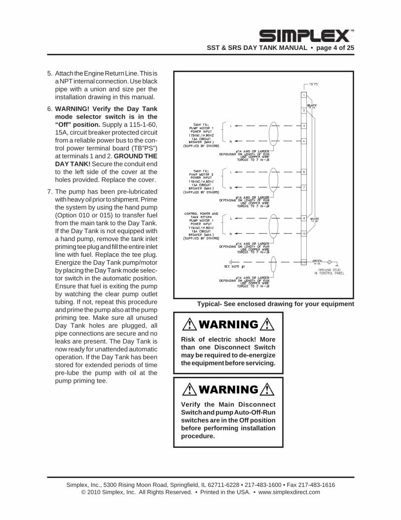
5. Attach the Engine Return Line. This is a NPT internal connection. Use black pipe with a union and size per the installation drawing in this manual.
6. WARNING! Verify the Day Tank mode selector switch is in the “Off” position. Supply a 115-1-60, 15A, circuit breaker protected circuit from a reliable power bus to the con-trol power terminal board (TB”PS”) at terminals 1 and 2. GROUND THE DAY TANK! Secure the conduit end to the left side of the cover at the holes provided. Replace the cover.
7. The pump has been pre-lubricated with heavy oil prior to shipment. Prime the system by using the hand pump (Option 010 or 015) to transfer fuel from the main tank to the Day Tank. If the Day Tank is not equipped with a hand pump, remove the tank inlet priming tee plug and fi ll the entire inlet line with fuel. Replace the tee plug. Energize the Day Tank pump/motor by placing the Day Tank mode selec-tor switch in the automatic position. Ensure that fuel is exiting the pump by watching the clear pump outlet tubing. If not, repeat this procedure and prime the pump also at the pump priming tee. Make sure all unused Day Tank holes are plugged, all pipe connections are secure and no leaks are present. The Day Tank is now ready for unattended automatic operation. If the Day Tank has been stored for extended periods of time pre-lube the pump with oil at the pump priming tee.
Risk of electric shock! More than one Disconnect Switch may be required to de-energize the equipment before servicing.
Verify the Main Disconnect Switch and pump Auto-Off-Run switches are in the Off position before performing installation procedure.
Typical- See enclosed drawing for your equipment
Simplex, Inc., 5300 Rising Moon Road, Springfi eld, IL 62711-6228 • 217-483-1600 • Fax 217-483-1616© 2010 Simplex, Inc. All Rights Reserved. • Printed in the USA. • www.simplexdirect.com
SST & SRS DAY TANK MANUAL • page 5 of 25
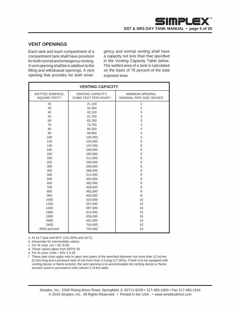
VENT OPENINGS
Each tank and each compartment of a compartment tank shall have provision for both normal and emergency venting. A vent opening shall be in addition to the fi lling and withdrawal openings. A vent opening that provides for both emer-
VENTING CAPACITY
WETTED SURFACE, VENTING CAPACITY, MINIMUM OPENING, SQUARE FEETb,c CUBIC FEET PER HOURd,e NOMINAL PIPE SIZE, INCHESf
20 21,100 2 30 31,600 2 40 42,100 3 50 52,700 3 60 63,200 3 70 73,700 4 80 84,200 4 90 94,800 4 100 105,000 4 120 126,000 5 140 147,000 5 160 168,000 5 180 190,000 5 200 211,000 6 250 239,000 6 300 265,000 6 350 288,000 8 400 312,000 8 500 354,000 8 600 392,000 8 700 428,000 8 800 462,000 8 900 493,000 8 1000 524,000 10 1200 557,000 10 1400 587,000 10 1600 614,000 10 1800 639,000 10 2000 662,000 10 2400 704,000 10 2800 and over 742,000 10
a At 14.7 psia and 60°F (101.4kPa and 16°C)b Interpolate for intermediate valuesc For SI units, m2 = ft2 /0.09.d These values taken from NFPA 30e For SI units, m3/s = ft/hr X 0.03f These pipe sizes apply only to open vent pipes of the specifi ed diameter not more than 12 inches
(0.3m) long and a pressure tank of not more than 2.5 psig (17.1kPa). If tank is to be equipped with venting device or fl ame arrestor, the vent opening is to accommodate the venting device or fl ame arrestor sized in accordance with column 2 of this table.
gency and normal venting shall have a capacity not less than that specifi ed in the Venting Capacity Table below. The wetted area of a tank is calculated on the basis of 75 percent of the total exposed area.
Simplex, Inc., 5300 Rising Moon Road, Springfi eld, IL 62711-6228 • 217-483-1600 • Fax 217-483-1616© 2010 Simplex, Inc. All Rights Reserved. • Printed in the USA. • www.simplexdirect.com
SST & SRS DAY TANK MANUAL • page 6 of 25
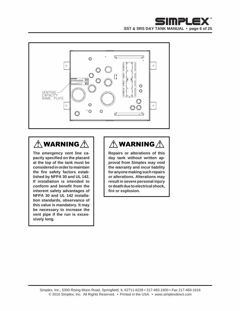
The emergency vent line ca-pacity specifi ed on the placard at the top of the tank must be considered in order to maintain the fi re safety factors estab-lished by NFPA 30 and UL 142. If installation is intended to conform and benefi t from the inherent safety advantages of NFPA 30 and UL 142 installa-tion standards, observance of this value is mandatory. It may be necessary to increase the vent pipe if the run is exces-sively long.
Repairs or alterations of this day tank without written ap-proval from Simplex may void the warranty and incur liability for anyone making such repairs or alterations. Alterations may result in severe personal injury or death due to electrical shock, fi re or explosion.
Simplex, Inc., 5300 Rising Moon Road, Springfi eld, IL 62711-6228 • 217-483-1600 • Fax 217-483-1616© 2010 Simplex, Inc. All Rights Reserved. • Printed in the USA. • www.simplexdirect.com
SST & SRS DAY TANK MANUAL • page 7 of 25
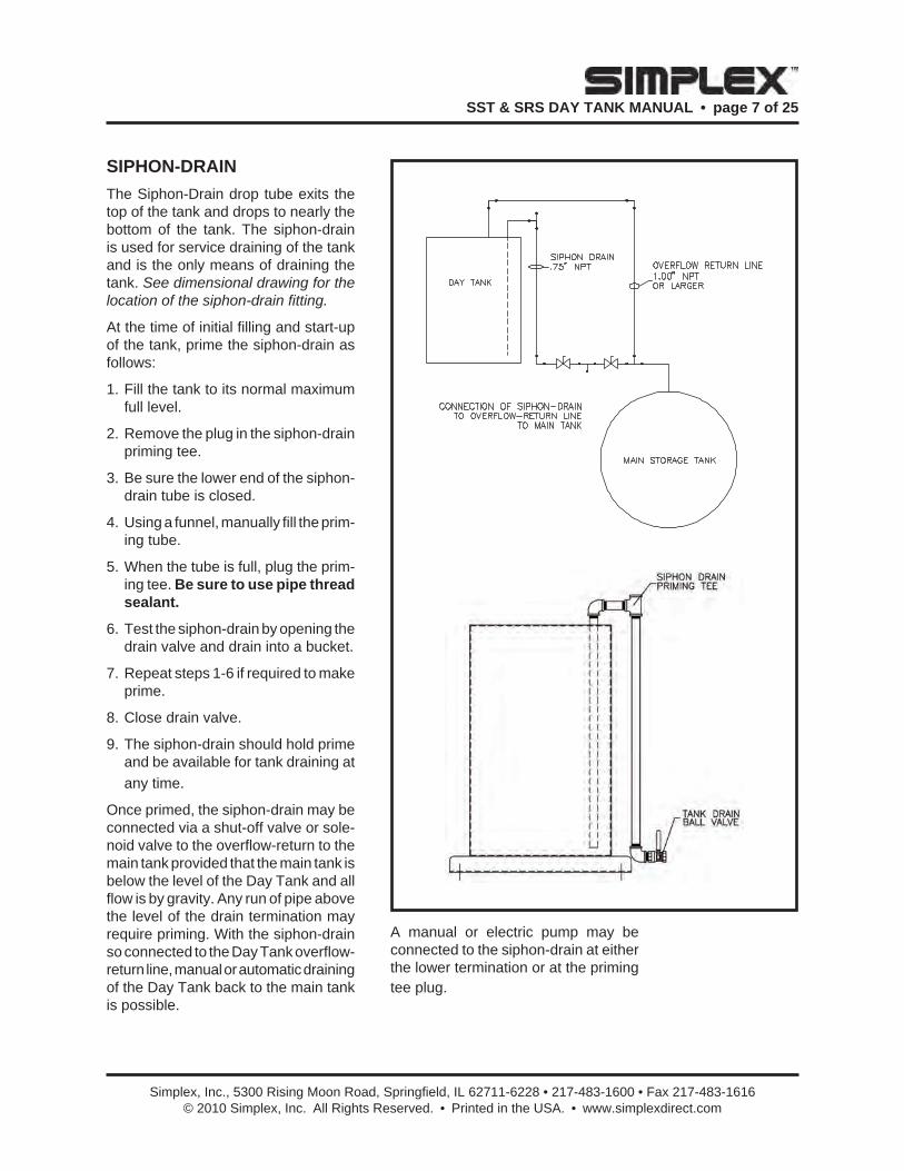
SIPHON-DRAIN
The Siphon-Drain drop tube exits the top of the tank and drops to nearly the bottom of the tank. The siphon-drain is used for service draining of the tank and is the only means of draining the tank. See dimensional drawing for the location of the siphon-drain fi tting.
At the time of initial fi lling and start-up of the tank, prime the siphon-drain as follows:
1. Fill the tank to its normal maximum full level.
2. Remove the plug in the siphon-drain priming tee.
3. Be sure the lower end of the siphon-drain tube is closed.
4. Using a funnel, manually fi ll the prim-ing tube.
5. When the tube is full, plug the prim-ing tee. Be sure to use pipe thread sealant.
6. Test the siphon-drain by opening the drain valve and drain into a bucket.
7. Repeat steps 1-6 if required to make prime.
8. Close drain valve.
9. The siphon-drain should hold prime and be available for tank draining at any time.
Once primed, the siphon-drain may be connected via a shut-off valve or sole-noid valve to the overfl ow-return to the main tank provided that the main tank is below the level of the Day Tank and all fl ow is by gravity. Any run of pipe above the level of the drain termination may require priming. With the siphon-drain so connected to the Day Tank overfl ow-return line, manual or automatic draining of the Day Tank back to the main tank is possible.
A manual or electric pump may be connected to the siphon-drain at either the lower termination or at the priming tee plug.
Simplex, Inc., 5300 Rising Moon Road, Springfi eld, IL 62711-6228 • 217-483-1600 • Fax 217-483-1616© 2010 Simplex, Inc. All Rights Reserved. • Printed in the USA. • www.simplexdirect.com
SST & SRS DAY TANK MANUAL • page 8 of 25
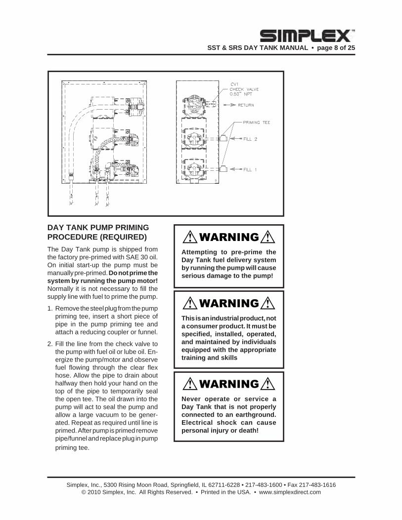
DAY TANK PUMP PRIMING PROCEDURE (REQUIRED)
The Day Tank pump is shipped from the factory pre-primed with SAE 30 oil. On initial start-up the pump must be manually pre-primed. Do not prime the system by running the pump motor! Normally it is not necessary to fi ll the supply line with fuel to prime the pump.
1. Remove the steel plug from the pump priming tee, insert a short piece of pipe in the pump priming tee and attach a reducing coupler or funnel.
2. Fill the line from the check valve to the pump with fuel oil or lube oil. En-ergize the pump/motor and observe fuel fl owing through the clear fl ex hose. Allow the pipe to drain about halfway then hold your hand on the top of the pipe to temporarily seal the open tee. The oil drawn into the pump will act to seal the pump and allow a large vacuum to be gener-ated. Repeat as required until line is primed. After pump is primed remove pipe/funnel and replace plug in pump priming tee.
Attempting to pre-prime the Day Tank fuel delivery system by running the pump will cause serious damage to the pump!
This is an industrial product, not a consumer product. It must be specifi ed, installed, operated, and maintained by individuals equipped with the appropriate training and skills
Never operate or service a Day Tank that is not properly connected to an earthground. Electrical shock can cause personal injury or death!
Simplex, Inc., 5300 Rising Moon Road, Springfi eld, IL 62711-6228 • 217-483-1600 • Fax 217-483-1616© 2010 Simplex, Inc. All Rights Reserved. • Printed in the USA. • www.simplexdirect.com
SST & SRS DAY TANK MANUAL • page 9 of 25
DAY TANK OPERATION
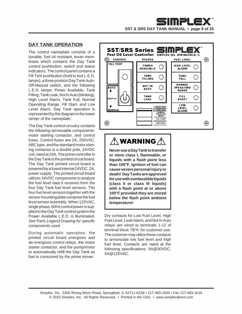
The control nameplate consists of a durable, fuel oil resistant, lexan mem-brane which contains the Day Tank control pushbutton, switch and status indicators. The control panel contains a Fill Test pushbutton (hold to test L.E.D. lamps), a three position Day Tank Auto-Off-Manual switch, and the following L.E.D. lamps: Power Available, Tank Filling, Tank Leak, Not In Auto (blinking), High Level Alarm, Tank Full, Normal Operating Range, Fill Start, and Low Level Alarm. Day Tank operation is represented by the diagram in the lower center of the nameplate.
The Day Tank control circuitry contains the following serviceable components: motor starting contactor, and control fuses. Control fuses are 2A, 250VAC, ABC type, and the standard motor start-ing contactor is a double pole, 24VDC coil, rated at 20A. The prime controller in the Day Tank is the printed circuit board. The Day Tank printed circuit board is powered by a fused internal 24VDC, 2A, power supply. The printed circuit board utilizes 24VDC components to analyze the fuel level data it receives from the four Day Tank fuel level sensors. The four fuel level sensors together with the sensor mounting plate comprise the fuel level sensor assembly. When 120VAC, single phase, 60Hz control power is sup-plied to the Day Tank control system the Power Available L.E.D. is illuminated. See Parts Legend Drawing for specifi c components used.
During automatic operation, the printed circuit board energizes and de-energizes control relays, the motor starter contactor, and the pump/motor to automatically refi ll the Day Tank as fuel is consumed by the prime mover.
Dry contacts for Low Fuel Level, High Fuel Level, Leak Alarm, and Not In Auto relays are wired to terminals 1-12 of terminal block TB‘A’ for customer use. The customer may utilize these contacts to annunciate low fuel level and high fuel level. Contacts are rated at the following specifi cations: 5A@30VDC, 5A@125VAC.
Never use a Day Tank to transfer or store class I, fl ammable, or liquids with a fl ash point less than 100°F. Ignition of fuel can cause severe personal injury or death! Day Tanks are approved for use with combustible liquids (class II or class III liquids) with a fl ash point at or above 100°F provided they are stored below the fl ash point ambient temperature!
Simplex, Inc., 5300 Rising Moon Road, Springfi eld, IL 62711-6228 • 217-483-1600 • Fax 217-483-1616© 2010 Simplex, Inc. All Rights Reserved. • Printed in the USA. • www.simplexdirect.com
SST & SRS DAY TANK MANUAL • page 10 of 25
AUTOMATIC OPERATION
The Day Tank mode selector switch should be left in the automatic position for normal unattended operation. Re-gardless of operating mode, the Pump Running L.E.D. will be illuminated any time the pump/motor is energized. The standard Day Tank motor is thermally protected. See Parts Legend Drawing for the pump/motor supplied with this work order. As the prime mover con-sumes fuel the Day Tank pump and motor will cycle through the normal operating range as determined by the fuel level sensors. The control panel L.E.D. lamps will continuously visually annunciate fuel level in the Day Tank.
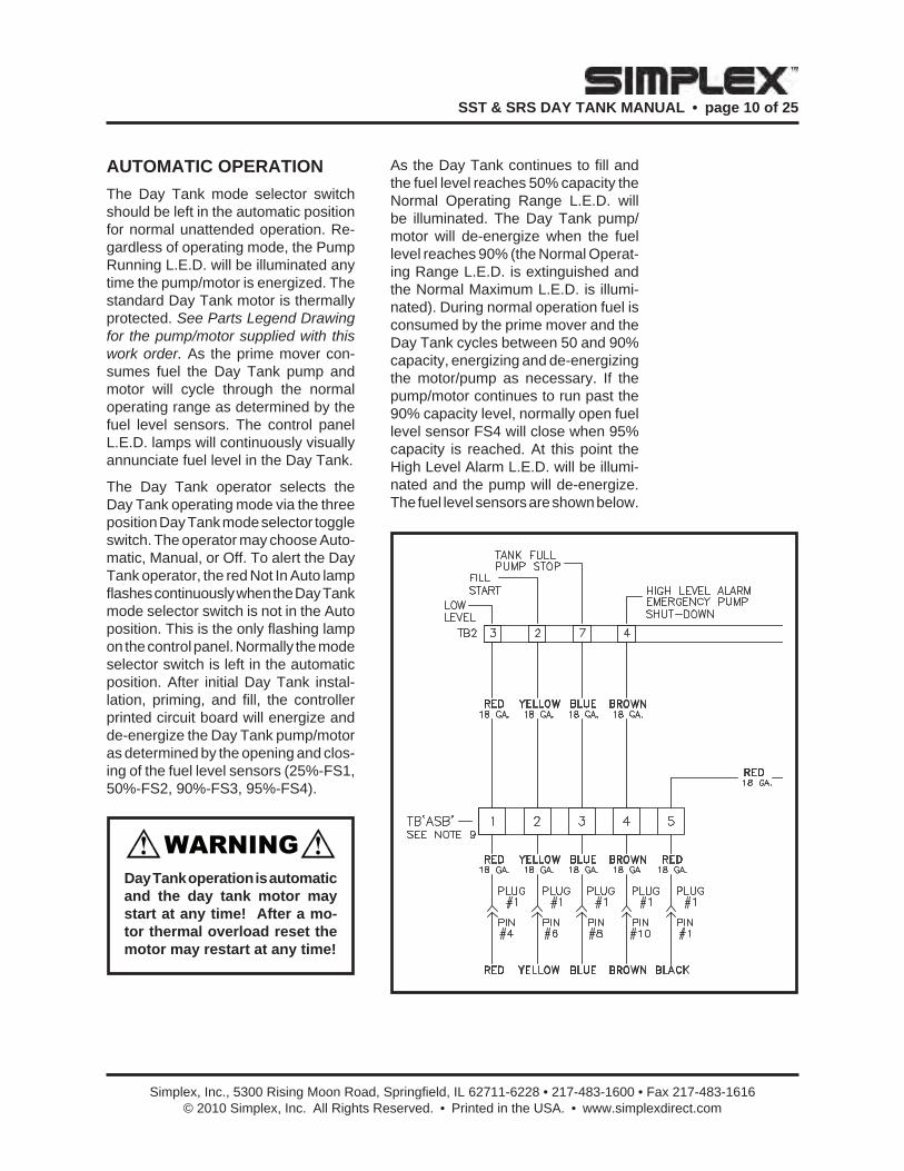
The Day Tank operator selects the Day Tank operating mode via the three position Day Tank mode selector toggle switch. The operator may choose Auto-matic, Manual, or Off. To alert the Day Tank operator, the red Not In Auto lamp fl ashes continuously when the Day Tank mode selector switch is not in the Auto position. This is the only fl ashing lamp on the control panel. Normally the mode selector switch is left in the automatic position. After initial Day Tank instal-lation, priming, and fi ll, the controller printed circuit board will energize and de-energize the Day Tank pump/motor as determined by the opening and clos-ing of the fuel level sensors (25%-FS1, 50%-FS2, 90%-FS3, 95%-FS4).
As the Day Tank continues to fi ll and the fuel level reaches 50% capacity the Normal Operating Range L.E.D. will be illuminated. The Day Tank pump/motor will de-energize when the fuel level reaches 90% (the Normal Operat-ing Range L.E.D. is extinguished and the Normal Maximum L.E.D. is illumi-nated). During normal operation fuel is consumed by the prime mover and the Day Tank cycles between 50 and 90% capacity, energizing and de-energizing the motor/pump as necessary. If the pump/motor continues to run past the 90% capacity level, normally open fuel level sensor FS4 will close when 95% capacity is reached. At this point the High Level Alarm L.E.D. will be illumi-nated and the pump will de-energize. The fuel level sensors are shown below.
Day Tank operation is automatic and the day tank motor may start at any time! After a mo-tor thermal overload reset the motor may restart at any time!
Simplex, Inc., 5300 Rising Moon Road, Springfi eld, IL 62711-6228 • 217-483-1600 • Fax 217-483-1616© 2010 Simplex, Inc. All Rights Reserved. • Printed in the USA. • www.simplexdirect.com
SST & SRS DAY TANK MANUAL • page 11 of 25
HIGH LEVEL FILL DISABLED
A High Level alarm causes the Day Tank to enter a new mode of operation dependent on the position of the mode selector switch.
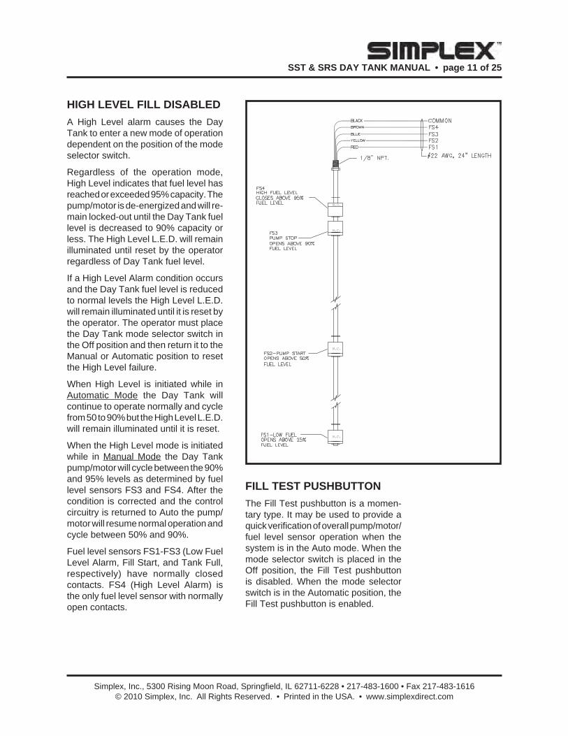
Regardless of the operation mode, High Level indicates that fuel level has reached or exceeded 95% capacity. The pump/motor is de-energized and will re-main locked-out until the Day Tank fuel level is decreased to 90% capacity or less. The High Level L.E.D. will remain illuminated until reset by the operator regardless of Day Tank fuel level.
If a High Level Alarm condition occurs and the Day Tank fuel level is reduced to normal levels the High Level L.E.D. will remain illuminated until it is reset by the operator. The operator must place the Day Tank mode selector switch in the Off position and then return it to the Manual or Automatic position to reset the High Level failure.
When High Level is initiated while in Automatic Mode the Day Tank will continue to operate normally and cycle from 50 to 90% but the High Level L.E.D. will remain illuminated until it is reset.
When the High Level mode is initiated while in Manual Mode the Day Tank pump/motor will cycle between the 90% and 95% levels as determined by fuel level sensors FS3 and FS4. After the condition is corrected and the control circuitry is returned to Auto the pump/motor will resume normal operation and cycle between 50% and 90%.
Fuel level sensors FS1-FS3 (Low Fuel Level Alarm, Fill Start, and Tank Full, respectively) have normally closed contacts. FS4 (High Level Alarm) is the only fuel level sensor with normally open contacts.
FILL TEST PUSHBUTTON
The Fill Test pushbutton is a momen-tary type. It may be used to provide a quick verifi cation of overall pump/motor/fuel level sensor operation when the system is in the Auto mode. When the mode selector switch is placed in the Off position, the Fill Test pushbutton is disabled. When the mode selector switch is in the Automatic position, the Fill Test pushbutton is enabled.
Simplex, Inc., 5300 Rising Moon Road, Springfi eld, IL 62711-6228 • 217-483-1600 • Fax 217-483-1616© 2010 Simplex, Inc. All Rights Reserved. • Printed in the USA. • www.simplexdirect.com
SST & SRS DAY TANK MANUAL • page 12 of 25
The operator may energize the pump/motor with the Test Fill pushbutton to test and cycle the Day Tank through the specifi ed capacity range. When the pump is operated by continuously holding the Fill Test pushbutton the pump/motor will continue to run past the normal stop level until 95% capacity is reached, at which point the pump/motor is de-energized and locked out by fuel level sensor FS4. The High Level L.E.D. will be illuminated and the High Level alarm relay will be energized. Contact rated 5A @ 30 VDC, 5A @ 125VAC maximum.
LOW LEVEL ALARM
During normal operation, the pump/mo-tor is energized and the Fill Start L.E.D. is illuminated when the Day Tank fuel level reaches 50% capacity. If the pump/motor does not energize a low fuel level alarm will be initiated when Day Tank fuel capacity reaches the 25% level. The low fuel alarm relay LFR energizes, the Low Level Alarm L.E.D. is illuminated, and LFR dry contacts close. The Day Tank user may utilize these contacts to sound an alarm horn or provide an input to a remote annunciator. Contacts are 5A @ 30VDC, 5A @ 125VAC maximum.
MANUAL OPERATION
For manual (continuous run) operation, the Day Tank operator must place the Day Tank mode selector toggle switch in the Manual position. Manual operation allows the Day Tank operator to ener-gize and run continuously the pump/motor independent of fuel level sensors FS1-FS3. During manual operation the control panel L.E.D. lamps will continue to annunciate fuel level to the Day Tank operator. The Day Tank will continue
to fi ll until 95% capacity is reached at which time the High Level mode will be initiated. The Day Tank pump/motor will be de-energized and locked out until Day Tank fuel level is reduced to 90% capacity and fuel level sensor FS3 changes state. Until the alarm condition is corrected and the control circuitry is reset to Auto the Day Tank pump/motor will continue to cycle between the 90% and 95% levels. Upon return to Auto, the control circuitry is reset and the pump/motor will resume normal operation and cycle between 50% and 90%.
REMOTE OPERATION
See Electrical Drawing. These Day Tanks are shipped with a jumper in-stalled on terminals TB‘2’ 8 and TB‘3’ 1 on the printed circuit board. Removing this jumer disables the pump/motor when in Auto mode. The Day Tank user has the option of installing a switch, remote disconnect, or overload relay to enable or disable the Day Tank pump/motor when in Auto mode. For example, a fuel sensor located in the Day Tank secondary containment (SST Options 190 and 191, SRS Standard) could be wired across these contacts to disable the pump/motor in the event of a Day Tank leak.
LAMP TEST
The momentary Fill Test pushbutton is also used to test L.E.D. lamps on the control board. To use this feature, press and hold the the Fill Test pushbutton to illuminate the L.E.D. lamps. If desired, the lamps may be tested without fi lling the tank further by placing the mode switch in the “Off” position before press-ing the Fill Test pushbutton.
Simplex, Inc., 5300 Rising Moon Road, Springfi eld, IL 62711-6228 • 217-483-1600 • Fax 217-483-1616© 2010 Simplex, Inc. All Rights Reserved. • Printed in the USA. • www.simplexdirect.com
SST & SRS DAY TANK MANUAL • page 13 of 25
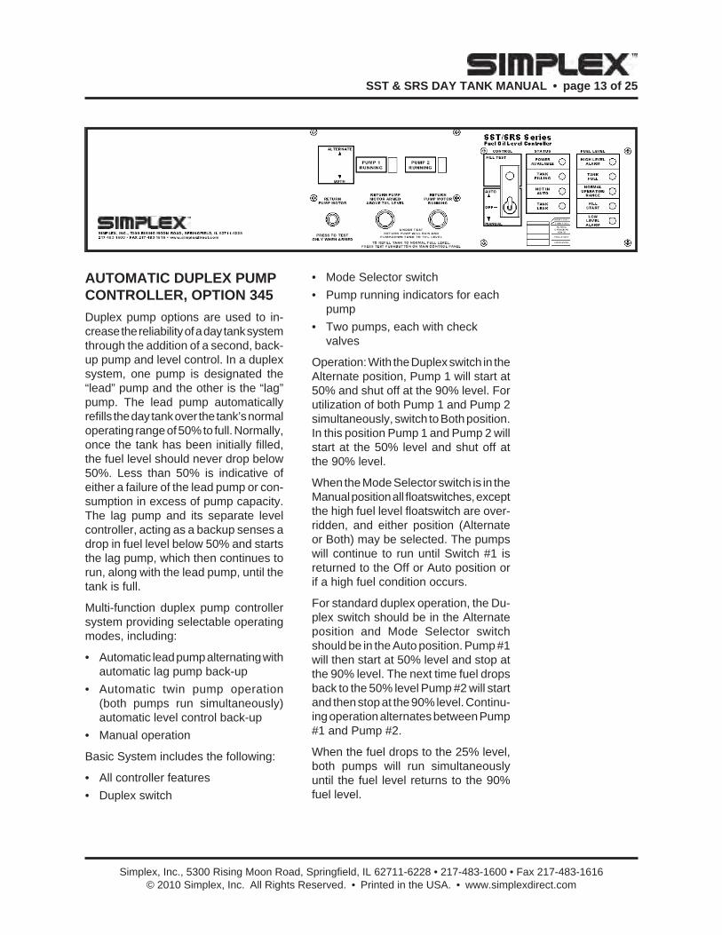
AUTOMATIC DUPLEX PUMP CONTROLLER, OPTION 345
Duplex pump options are used to in-crease the reliability of a day tank system through the addition of a second, back-up pump and level control. In a duplex system, one pump is designated the “lead” pump and the other is the “lag” pump. The lead pump automatically refi lls the day tank over the tank’s normal operating range of 50% to full. Normally, once the tank has been initially fi lled, the fuel level should never drop below 50%. Less than 50% is indicative of either a failure of the lead pump or con-sumption in excess of pump capacity. The lag pump and its separate level controller, acting as a backup senses a drop in fuel level below 50% and starts the lag pump, which then continues to run, along with the lead pump, until the tank is full.
Multi-function duplex pump controller system providing selectable operating modes, including:
• Automatic lead pump alternating with automatic lag pump back-up
• Automatic twin pump operation (both pumps run simultaneously) automatic level control back-up
• Manual operation
Basic System includes the following:
• All controller features
• Duplex switch
• Mode Selector switch
• Pump running indicators for each pump
• Two pumps, each with check valves
Operation: With the Duplex switch in the Alternate position, Pump 1 will start at 50% and shut off at the 90% level. For utilization of both Pump 1 and Pump 2 simultaneously, switch to Both position. In this position Pump 1 and Pump 2 will start at the 50% level and shut off at the 90% level.
When the Mode Selector switch is in the Manual position all fl oatswitches, except the high fuel level fl oatswitch are over-ridden, and either position (Alternate or Both) may be selected. The pumps will continue to run until Switch #1 is returned to the Off or Auto position or if a high fuel condition occurs.
For standard duplex operation, the Du-plex switch should be in the Alternate position and Mode Selector switch should be in the Auto position. Pump #1 will then start at 50% level and stop at the 90% level. The next time fuel drops back to the 50% level Pump #2 will start and then stop at the 90% level. Continu-ing operation alternates between Pump #1 and Pump #2.
When the fuel drops to the 25% level, both pumps will run simultaneously until the fuel level returns to the 90% fuel level.
Simplex, Inc., 5300 Rising Moon Road, Springfi eld, IL 62711-6228 • 217-483-1600 • Fax 217-483-1616© 2010 Simplex, Inc. All Rights Reserved. • Printed in the USA. • www.simplexdirect.com
SST & SRS DAY TANK MANUAL • page 14 of 25
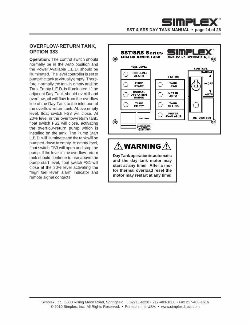
OVERFLOW-RETURN TANK, OPTION 383
Operation: The control switch should normally be in the Auto position and the Power Available L.E.D. should be illuminated. The level controller is set to pump the tank to virtually empty. There-fore, normally the tank is empty and the Tank Empty L.E.D. is illuminated. If the adjacent Day Tank should overfi ll and overfl ow, oil will fl ow from the overfl ow line of the Day Tank to the inlet port of the overfl ow-return tank. Above empty level, fl oat switch FS3 will close. At 20% level in the overfl ow-return tank, fl oat switch FS2 will close, activating the overflow-return pump which is installed on the tank. The Pump Start L.E.D. will illuminate and the tank will be pumped-down to empty. At empty level, fl oat switch FS3 will open and stop the pump. If the level in the overfl ow-return tank should continue to rise above the pump start level, fl oat switch FS1 will close at the 30% level activating the “high fuel level” alarm indicator and remote signal contacts.
Day Tank operation is automatic and the day tank motor may start at any time! After a mo-tor thermal overload reset the motor may restart at any time!
Simplex, Inc., 5300 Rising Moon Road, Springfi eld, IL 62711-6228 • 217-483-1600 • Fax 217-483-1616© 2010 Simplex, Inc. All Rights Reserved. • Printed in the USA. • www.simplexdirect.com
SST & SRS DAY TANK MANUAL • page 15 of 25
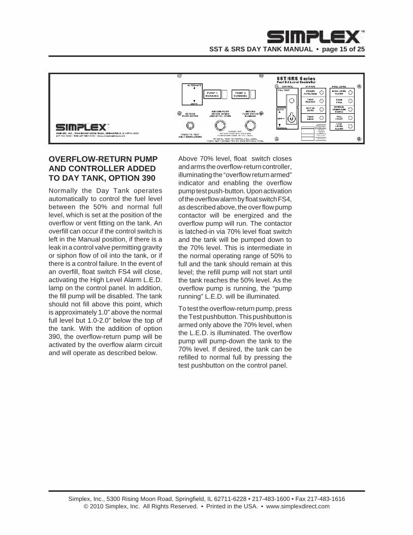
OVERFLOW-RETURN PUMP AND CONTROLLER ADDED TO DAY TANK, OPTION 390
Normally the Day Tank operates automatically to control the fuel level between the 50% and normal full level, which is set at the position of the overfl ow or vent fi tting on the tank. An overfi ll can occur if the control switch is left in the Manual position, if there is a leak in a control valve permitting gravity or siphon fl ow of oil into the tank, or if there is a control failure. In the event of an overfi ll, fl oat switch FS4 will close, activating the High Level Alarm L.E.D. lamp on the control panel. In addition, the fi ll pump will be disabled. The tank should not fi ll above this point, which is approximately 1.0” above the normal full level but 1.0-2.0” below the top of the tank. With the addition of option 390, the overfl ow-return pump will be activated by the overfl ow alarm circuit and will operate as described below.
Above 70% level, fl oat switch closes and arms the overfl ow-return controller, illuminating the “overfl ow return armed” indicator and enabling the overfl ow pump test push-button. Upon activation of the overfl ow alarm by fl oat switch FS4, as described above, the over fl ow pump contactor will be energized and the overfl ow pump will run. The contactor is latched-in via 70% level fl oat switch and the tank will be pumped down to the 70% level. This is intermediate in the normal operating range of 50% to full and the tank should remain at this level; the refi ll pump will not start until the tank reaches the 50% level. As the overfl ow pump is running, the “pump running” L.E.D. will be illuminated.
To test the overfl ow-return pump, press the Test pushbutton. This pushbutton is armed only above the 70% level, when the L.E.D. is illuminated. The overfl ow pump will pump-down the tank to the 70% level. If desired, the tank can be refi lled to normal full by pressing the test pushbutton on the control panel.
Simplex, Inc., 5300 Rising Moon Road, Springfi eld, IL 62711-6228 • 217-483-1600 • Fax 217-483-1616© 2010 Simplex, Inc. All Rights Reserved. • Printed in the USA. • www.simplexdirect.com
SST & SRS DAY TANK MANUAL • page 16 of 25
MAINTENANCE
The Simplex Day Tank has been designed to require minimum main-tenance. All components have been chosen for a long, reliable life. The Day Tank is constantly lubricated by the diesel fuel it transfers. Inspect this tank at least once every year for dam-age, leakage, or rust on both inside and outside the tank. Promptly repair or replace any signifi cantly damaged or deteriorated Day Tank. Two basic intervals of maintenance are required: each year and after the fi rst 3 years.
EACH YEAR
1. Water and sediment should be drained from the tank each year. If normal engine/generator testing does not consume one tank full of fuel each year the tank should be drained and refi lled with fresh fuel.
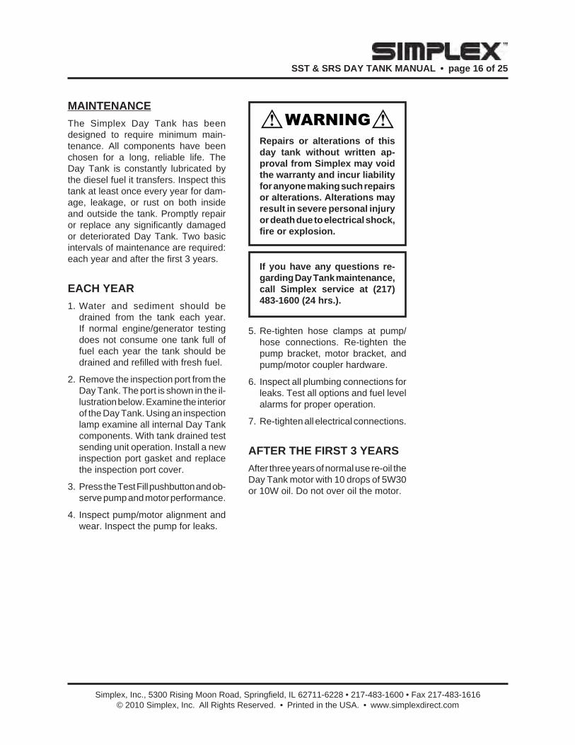
2. Remove the inspection port from the Day Tank. The port is shown in the il-lustration below. Examine the interior of the Day Tank. Using an inspection lamp examine all internal Day Tank components. With tank drained test sending unit operation. Install a new inspection port gasket and replace the inspection port cover.
3. Press the Test Fill pushbutton and ob-serve pump and motor performance.
4. Inspect pump/motor alignment and wear. Inspect the pump for leaks.
5. Re-tighten hose clamps at pump/hose connections. Re-tighten the pump bracket, motor bracket, and pump/motor coupler hardware.
6. Inspect all plumbing connections for leaks. Test all options and fuel level alarms for proper operation.
7. Re-tighten all electrical connections.
AFTER THE FIRST 3 YEARS
After three years of normal use re-oil the Day Tank motor with 10 drops of 5W30 or 10W oil. Do not over oil the motor.
If you have any questions re-garding Day Tank maintenance, call Simplex service at (217) 483-1600 (24 hrs.).
Repairs or alterations of this day tank without written ap-proval from Simplex may void the warranty and incur liability for anyone making such repairs or alterations. Alterations may result in severe personal injury or death due to electrical shock, fi re or explosion.
Simplex, Inc., 5300 Rising Moon Road, Springfi eld, IL 62711-6228 • 217-483-1600 • Fax 217-483-1616© 2010 Simplex, Inc. All Rights Reserved. • Printed in the USA. • www.simplexdirect.com
SST & SRS DAY TANK MANUAL • page 17 of 25
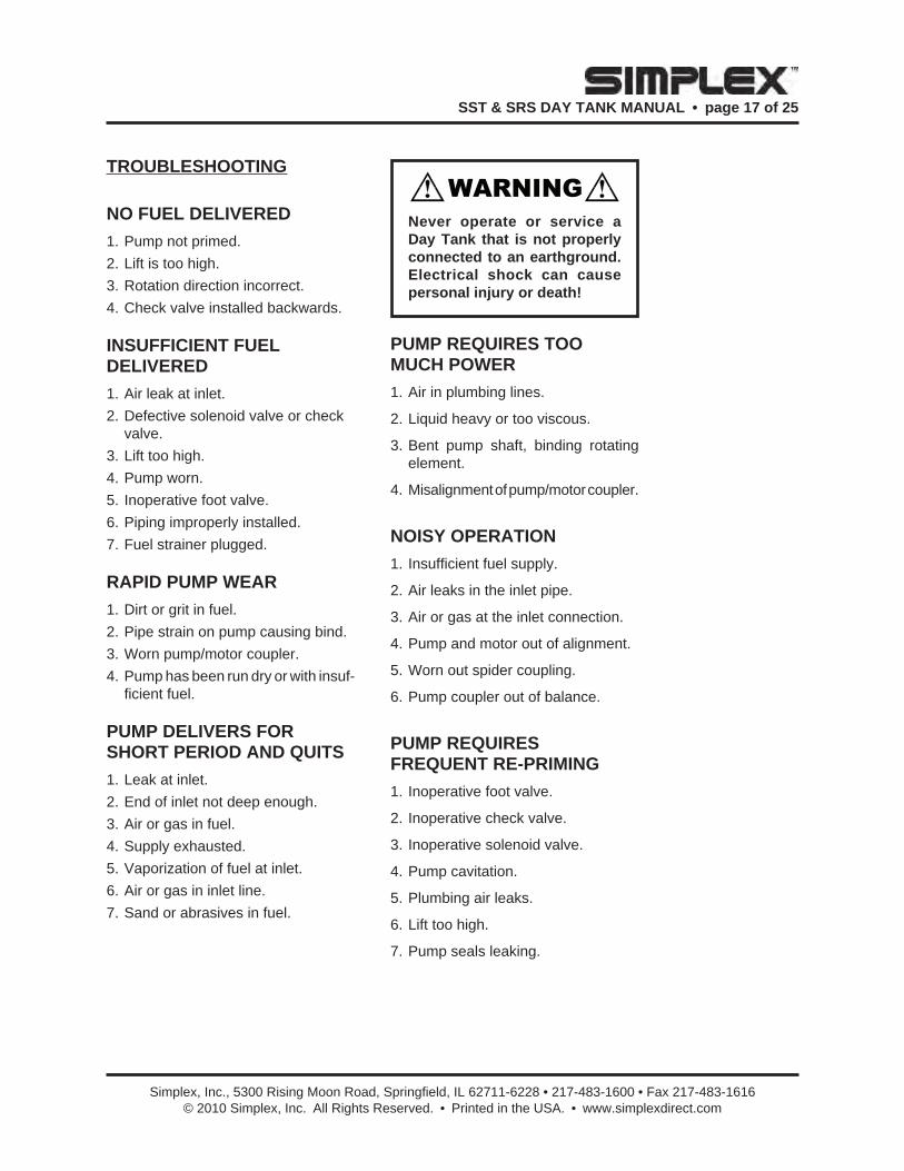
TROUBLESHOOTING
NO FUEL DELIVERED
1. Pump not primed.
2. Lift is too high.
3. Rotation direction incorrect.
4. Check valve installed backwards.
INSUFFICIENT FUEL DELIVERED
1. Air leak at inlet.
2. Defective solenoid valve or check valve.
3. Lift too high.
4. Pump worn.
5. Inoperative foot valve.
6. Piping improperly installed.
7. Fuel strainer plugged.
RAPID PUMP WEAR
1. Dirt or grit in fuel.
2. Pipe strain on pump causing bind.
3. Worn pump/motor coupler.
4. Pump has been run dry or with insuf-fi cient fuel.
PUMP DELIVERS FOR SHORT PERIOD AND QUITS
1. Leak at inlet.
2. End of inlet not deep enough.
3. Air or gas in fuel.
4. Supply exhausted.
5. Vaporization of fuel at inlet.
6. Air or gas in inlet line.
7. Sand or abrasives in fuel.
PUMP REQUIRES TOO MUCH POWER
1. Air in plumbing lines.
2. Liquid heavy or too viscous.
3. Bent pump shaft, binding rotating element.
4. Misalignment of pump/motor coupler.
NOISY OPERATION
1. Insuffi cient fuel supply.
2. Air leaks in the inlet pipe.
3. Air or gas at the inlet connection.
4. Pump and motor out of alignment.
5. Worn out spider coupling.
6. Pump coupler out of balance.
PUMP REQUIRES FREQUENT RE-PRIMING
1. Inoperative foot valve.
2. Inoperative check valve.
3. Inoperative solenoid valve.
4. Pump cavitation.
5. Plumbing air leaks.
6. Lift too high.
7. Pump seals leaking.
Never operate or service a Day Tank that is not properly connected to an earthground. Electrical shock can cause personal injury or death!
Simplex, Inc., 5300 Rising Moon Road, Springfi eld, IL 62711-6228 • 217-483-1600 • Fax 217-483-1616© 2010 Simplex, Inc. All Rights Reserved. • Printed in the USA. • www.simplexdirect.com
SST & SRS DAY TANK MANUAL • page 18 of 25
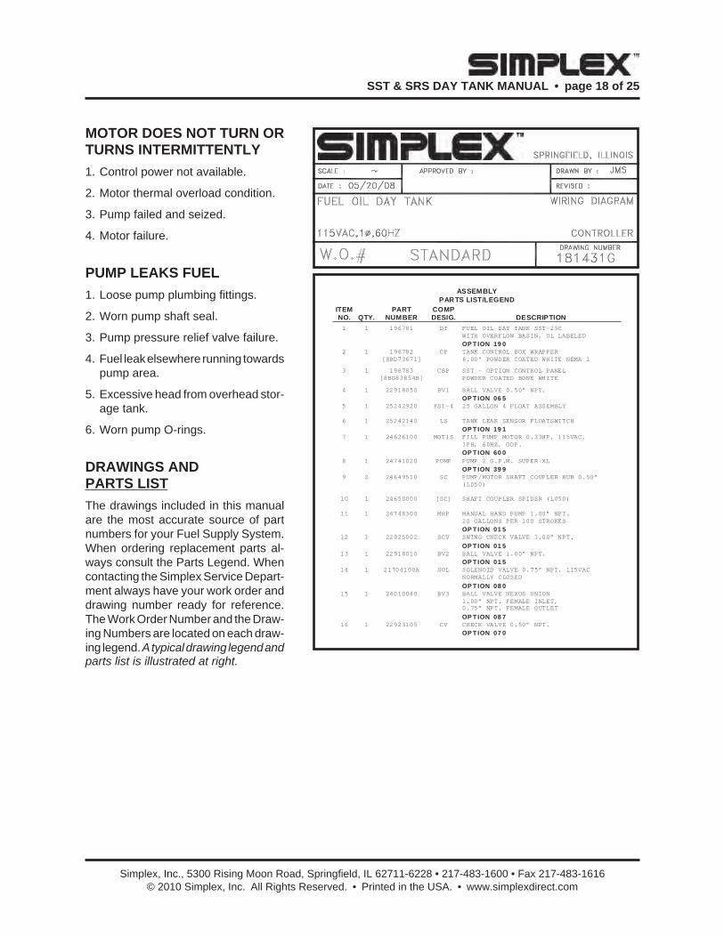
MOTOR DOES NOT TURN OR TURNS INTERMITTENTLY
1. Control power not available.
2. Motor thermal overload condition.
3. Pump failed and seized.
4. Motor failure.
PUMP LEAKS FUEL
1. Loose pump plumbing fi ttings.
2. Worn pump shaft seal.
3. Pump pressure relief valve failure.
4. Fuel leak elsewhere running towards pump area.
5. Excessive head from overhead stor-age tank.
6. Worn pump O-rings.
DRAWINGS ANDPARTS LIST
The drawings included in this manual are the most accurate source of part numbers for your Fuel Supply System. When ordering replacement parts al-ways consult the Parts Legend. When contacting the Simplex Service Depart-ment always have your work order and drawing number ready for reference. The Work Order Number and the Draw-ing Numbers are located on each draw-ing legend. A typical drawing legend and parts list is illustrated at right.
ASSEMBLY PARTS LIST/LEGEND
ITEM NO. QTY.
PART NUMBER
COMP DESIG. DESCRIPTION
1 1 196781 DT FUEL OIL DAY TANK SST-25C WITH OVERFLOW BASIN, UL LABELED OPTION 190
2 1 196782 [8BD73671]
CP TANK CONTROL BOX WRAPPER 6.00" POWDER COATED WHITE NEMA 1
3 1 196783 [8BD83854B]
CBP SST – OPTION CONTROL PANELPOWDER COATED BONE WHITE
4 1 22918050 BV1 BALL VALVE 0.50” NPT. OPTION 065
5 1 25242920 FS1-4 25 GALLON 4 FLOAT ASSEMBLY
6 1 25242140 LS TANK LEAK SENSOR FLOATSWITCH OPTION 191
7 1 24626100 MOT1S FILL PUMP MOTOR 0.33HP, 115VAC,1PH, 60HZ, ODP. OPTION 600
8 1 24741020 PUMP PUMP 2 G.P.M. SUPER XL OPTION 399
9 2 24649510 SC PUMP/MOTOR SHAFT COUPLER HUB 0.50”(L050)
10 1 24650000 [SC] SHAFT COUPLER SPIDER (L050)
11 1 24748300 MHP MANUAL HAND PUMP 1.00” NPT. 20 GALLONS PER 100 STROKES OPTION 015
12 1 22925002 SCV SWING CHECK VALVE 1.00” NPT. OPTION 015
13 1 22918010 BV2 BALL VALVE 1.00” NPT. OPTION 015
14 1 21704100A SOL SOLENOID VALVE 0.75” NPT. 115VACNORMALLY CLOSED OPTION 080
15 1 24010040 BV3 BALL VALVE NEXUS UNION 1.00” NPT. FEMALE INLET, 0.75” NPT. FEMALE OUTLET OPTION 087
16 1 22923105 CV CHECK VALVE 0.50” NPT. OPTION 070
Simplex, Inc., 5300 Rising Moon Road, Springfi eld, IL 62711-6228 • 217-483-1600 • Fax 217-483-1616© 2010 Simplex, Inc. All Rights Reserved. • Printed in the USA. • www.simplexdirect.com
SST & SRS DAY TANK MANUAL • page 19 of 25
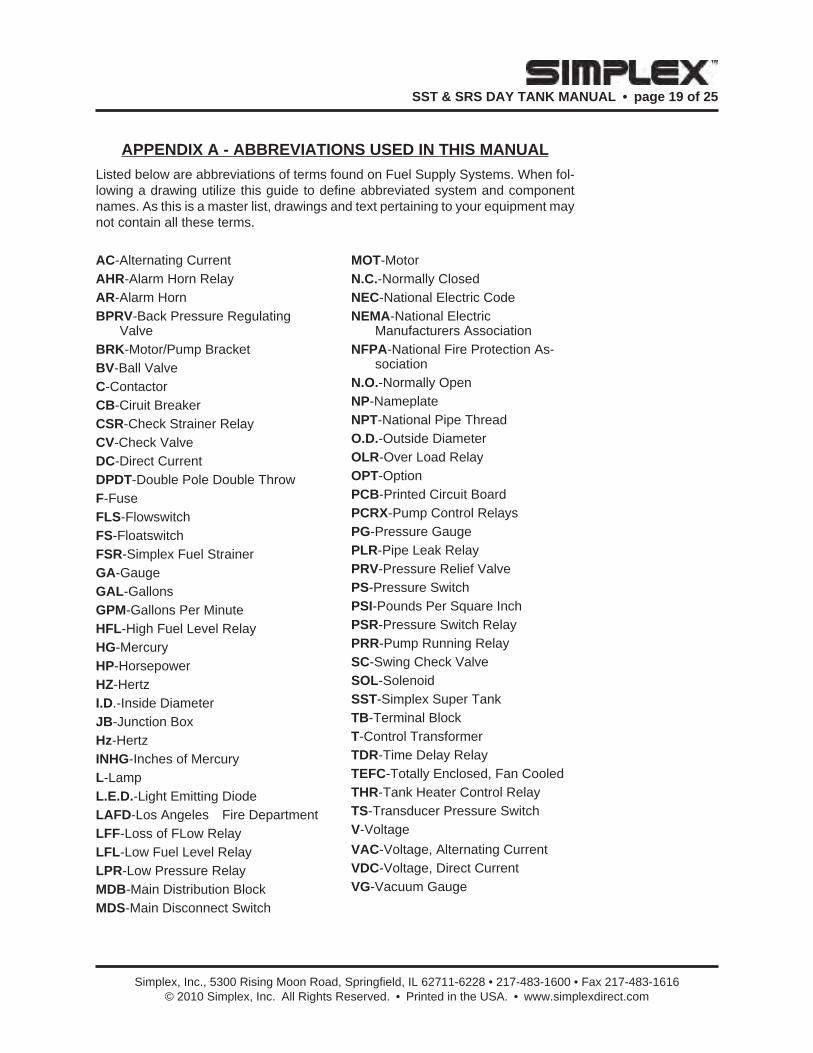
APPENDIX A - ABBREVIATIONS USED IN THIS MANUAL
Listed below are abbreviations of terms found on Fuel Supply Systems. When fol-lowing a drawing utilize this guide to defi ne abbreviated system and component names. As this is a master list, drawings and text pertaining to your equipment may not contain all these terms.
AC-Alternating CurrentAHR-Alarm Horn RelayAR-Alarm HornBPRV-Back Pressure Regulating
ValveBRK-Motor/Pump BracketBV-Ball ValveC-ContactorCB-Ciruit BreakerCSR-Check Strainer RelayCV-Check ValveDC-Direct CurrentDPDT-Double Pole Double ThrowF-FuseFLS-FlowswitchFS-FloatswitchFSR-Simplex Fuel StrainerGA-GaugeGAL-GallonsGPM-Gallons Per MinuteHFL-High Fuel Level RelayHG-MercuryHP-HorsepowerHZ-HertzI.D.-Inside DiameterJB-Junction BoxHz-HertzINHG-Inches of MercuryL-LampL.E.D.-Light Emitting DiodeLAFD-Los Angeles Fire DepartmentLFF-Loss of FLow RelayLFL-Low Fuel Level RelayLPR-Low Pressure RelayMDB-Main Distribution BlockMDS-Main Disconnect Switch
MOT-MotorN.C.-Normally ClosedNEC-National Electric CodeNEMA-National Electric
Manufacturers AssociationNFPA-National Fire Protection As-
sociationN.O.-Normally OpenNP-NameplateNPT-National Pipe ThreadO.D.-Outside DiameterOLR-Over Load RelayOPT-OptionPCB-Printed Circuit BoardPCRX-Pump Control RelaysPG-Pressure GaugePLR-Pipe Leak RelayPRV-Pressure Relief ValvePS-Pressure SwitchPSI-Pounds Per Square InchPSR-Pressure Switch RelayPRR-Pump Running RelaySC-Swing Check ValveSOL-SolenoidSST-Simplex Super TankTB-Terminal BlockT-Control TransformerTDR-Time Delay RelayTEFC-Totally Enclosed, Fan CooledTHR-Tank Heater Control RelayTS-Transducer Pressure SwitchV-Voltage
VAC-Voltage, Alternating CurrentVDC-Voltage, Direct CurrentVG-Vacuum Gauge
Simplex, Inc., 5300 Rising Moon Road, Springfi eld, IL 62711-6228 • 217-483-1600 • Fax 217-483-1616© 2010 Simplex, Inc. All Rights Reserved. • Printed in the USA. • www.simplexdirect.com
SST & SRS DAY TANK MANUAL • page 20 of 25
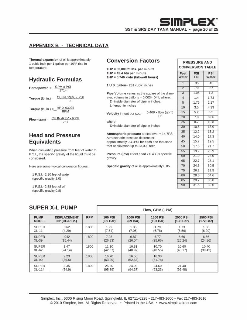
APPENDIX B - TECHNICAL DATA
Conversion Factors1HP = 33,000 ft. lbs. per minute1HP = 42.4 btu per minute1HP = 0.746 kwhr (kilowatt hours)
1 U.S. gallon= 231 cubic inches
Pipe Volume varies as the square of the diam-eter; volume in gallons = 0.0034 D 2 L where: D=inside diameter of pipe in inches; L=length in inches
Velocity in feet per sec.= 0.408 x fl ow (gpm) D2
where: D=inside diameter of pipe in inches
Atmospheric pressure at sea level = 14.7PSIAtmospheric pressure decreases approximately 0.41PSI for each one thousand feet of elevation up to 23,000 feet.
Pressure (PSI) = feet head x 0.433 x specifi c gravity
Specifi c gravity of oil is approximately 0.85.
Thermal expansion of oil is approximately 1 cubic inch per 1 gallon per 10°F rise in temperature.
Hydraulic FormulasHorsepower = GPM x PSI 1714
Torque (lb. in.) = CU IN./REV. x PSI 2
Torque (lb. in.) = HP X 63025 RPM
Flow (gpm) = CU IN./REV x RPM 231
Head and Pressure EquivalentsWhen converting pressure from feet of water to P.S.I., the specifi c gravity of the liquid must be considered.
Here are some typical conversion fi gures:
1 P.S.I.=2.30 feet of water (specifi c gravity 1.0)
1 P.S.I.=2.88 feet of oil (specifi c gravity 0.8)
PRESSURE ANDCONVERSION TABLE
Feet PSI PSI Water Oil Water
1 .35 .43
2 .70 .87
3 1.05 1.3
4 1.4 1.73
5 1.75 2.17
10 3.5 4.33
15 5.2 6.5
20 7.0 8.66
25 8.7 10.8
30 10.5 13.0
35 12.2 15.2
40 14.0 17.3
45 15.7 19.5
50 17.5 21.7
55 19.2 23.9
60 21.0 26.0
65 22.7 28.1
70 24.5 30.5
75 26.2 32.5
80 28.0 34.6
85 29.7 36.8
90 31.5 39.0
SUPER X-L PUMP Flow, GPM (LPM)
PUMP DISPLACEMENT RPM 100 PSI 1000 PSI 1500 PSI 2000 PSI 2500 PSI MODEL IN3 (CC/REV.) (6.9 Bar) (69 Bar) (103 Bar) (138 Bar) (172 Bar)
SUPER .262 1800 1.99 1.86 1.79 1.73 1.66 XL-11 (4.29) (7.54) (7.05) (6.78) (6.56) (6.29)
SUPER .942 1800 7.08 6.87 6.77 6.66 6.56 XL-39 (15.44) (26.83) (26.04) (25.66) (25.24) (24.86)
SUPER 1.47 1800 11.10 10.81 10.70 10.60 10.40 XL-62 (24.14) (42.07) (40.97) (40.55) (40.17) (39.42)
SUPER 2.23 1800 16.70 16.50 16.30 XL-90 (36.5) (63.29) (62.54) (61.78)
SUPER 3.35 1800 25.30 24.90 24.60 24.40 XL-114 (54.9) (95.89) (94.37) (93.23) (92.48)
Simplex, Inc., 5300 Rising Moon Road, Springfi eld, IL 62711-6228 • 217-483-1600 • Fax 217-483-1616© 2010 Simplex, Inc. All Rights Reserved. • Printed in the USA. • www.simplexdirect.com
SST & SRS DAY TANK MANUAL • page 21 of 25
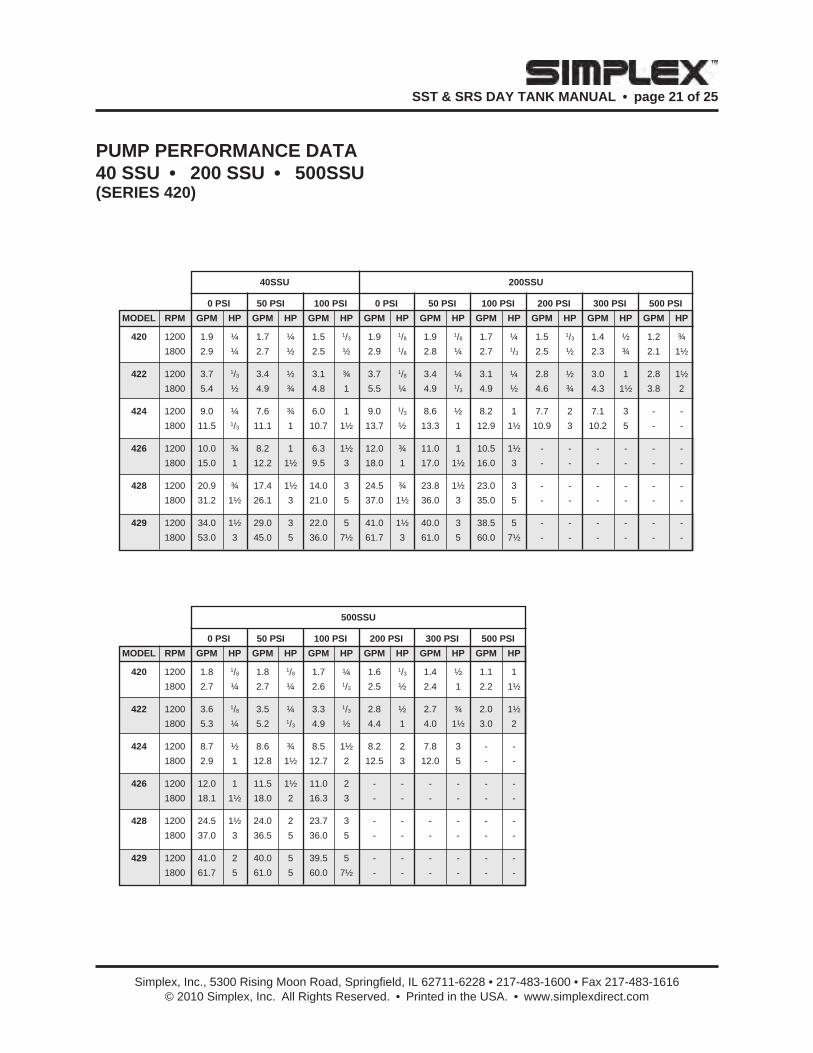
PUMP PERFORMANCE DATA 40 SSU • 200 SSU • 500SSU(SERIES 420)
40SSU 200SSU
0 PSI 50 PSI 100 PSI 0 PSI 50 PSI 100 PSI 200 PSI 300 PSI 500 PSI
MODEL RPM GPM HP GPM HP GPM HP GPM HP GPM HP GPM HP GPM HP GPM HP GPM HP
420 1200 1.9 ¼ 1.7 ¼ 1.5 1/3 1.9 1/8 1.9 1/8 1.7 ¼ 1.5 1/3 1.4 ½ 1.2 ¾
1800 2.9 ¼ 2.7 ½ 2.5 ½ 2.9 1/8 2.8 ¼ 2.7 1/3 2.5 ½ 2.3 ¾ 2.1 1½
422 1200 3.7 1/3 3.4 ½ 3.1 ¾ 3.7 1/8 3.4 ¼ 3.1 ¼ 2.8 ½ 3.0 1 2.8 1½
1800 5.4 ½ 4.9 ¾ 4.8 1 5.5 ¼ 4.9 1/3 4.9 ½ 4.6 ¾ 4.3 1½ 3.8 2
424 1200 9.0 ¼ 7.6 ¾ 6.0 1 9.0 1/3 8.6 ½ 8.2 1 7.7 2 7.1 3 - -
1800 11.5 1/3 11.1 1 10.7 1½ 13.7 ½ 13.3 1 12.9 1½ 10.9 3 10.2 5 - -
426 1200 10.0 ¾ 8.2 1 6.3 1½ 12.0 ¾ 11.0 1 10.5 1½ - - - - - -
1800 15.0 1 12.2 1½ 9.5 3 18.0 1 17.0 1½ 16.0 3 - - - - - -
428 1200 20.9 ¾ 17.4 1½ 14.0 3 24.5 ¾ 23.8 1½ 23.0 3 - - - - - -
1800 31.2 1½ 26.1 3 21.0 5 37.0 1½ 36.0 3 35.0 5 - - - - - -
429 1200 34.0 1½ 29.0 3 22.0 5 41.0 1½ 40.0 3 38.5 5 - - - - - -
1800 53.0 3 45.0 5 36.0 7½ 61.7 3 61.0 5 60.0 7½ - - - - - -
500SSU
0 PSI 50 PSI 100 PSI 200 PSI 300 PSI 500 PSI
MODEL RPM GPM HP GPM HP GPM HP GPM HP GPM HP GPM HP
420 1200 1.8 1/8 1.8 1/8 1.7 ¼ 1.6 1/3 1.4 ½ 1.1 1
1800 2.7 ¼ 2.7 ¼ 2.6 1/3 2.5 ½ 2.4 1 2.2 1½
422 1200 3.6 1/8 3.5 ¼ 3.3 1/3 2.8 ½ 2.7 ¾ 2.0 1½
1800 5.3 ¼ 5.2 1/3 4.9 ½ 4.4 1 4.0 1½ 3.0 2
424 1200 8.7 ½ 8.6 ¾ 8.5 1½ 8.2 2 7.8 3 - -
1800 2.9 1 12.8 1½ 12.7 2 12.5 3 12.0 5 - -
426 1200 12.0 1 11.5 1½ 11.0 2 - - - - - -
1800 18.1 1½ 18.0 2 16.3 3 - - - - - -
428 1200 24.5 1½ 24.0 2 23.7 3 - - - - - -
1800 37.0 3 36.5 5 36.0 5 - - - - - -
429 1200 41.0 2 40.0 5 39.5 5 - - - - - -
1800 61.7 5 61.0 5 60.0 7½ - - - - - -
Simplex, Inc., 5300 Rising Moon Road, Springfi eld, IL 62711-6228 • 217-483-1600 • Fax 217-483-1616© 2010 Simplex, Inc. All Rights Reserved. • Printed in the USA. • www.simplexdirect.com
SST & SRS DAY TANK MANUAL • page 22 of 25
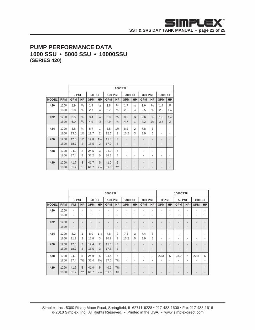
PUMP PERFORMANCE DATA 1000 SSU • 5000 SSU • 10000SSU(SERIES 420)
1000SSU
0 PSI 50 PSI 100 PSI 200 PSI 300 PSI 500 PSI
MODEL RPM GPM HP GPM HP GPM HP GPM HP GPM HP GPM HP
420 1200 1.9 1/8 1.9 1/8 1.8 ¼ 1.7 1/3 1.6 ½ 1.4 ¾
1800 2.8 ¼ 2.7 ¼ 2.7 ¼ 2.6 ½ 2.5 ¾ 2.2 1½
422 1200 3.5 ¼ 3.4 ¼ 3.3 1/3 3.0 ¾ 2.6 ¾ 1.8 1½
1800 5.0 1/3 4.9 ½ 4.9 ¾ 4.7 1 4.2 1½ 3.4 2
424 1200 8.8 ¾ 8.7 1 8.5 1½ 8.2 2 7.8 3 - -
1800 13.0 1½ 12.7 2 12.5 2 10.2 3 9.9 5 - -
426 1200 12.5 1½ 12.0 1½ 11.8 2 - - - - - -
1800 18.7 2 18.5 2 17.0 3 - - - - - -
428 1200 24.9 2 24.5 3 24.0 5 - - - - - -
1800 37.4 5 37.2 5 36.5 5 - - - - - -
429 1200 41.7 3 41.7 5 41.0 5 - - - - - -
1800 61.7 5 61.7 7½ 61.0 7½ - - - - - -
5000SSU 10000SSU
0 PSI 50 PSI 100 PSI 200 PSI 300 PSI 0 PSI 50 PSI 100 PSI
MODEL RPM PM HP GPM HP GPM HP GPM HP GPM HP GPM HP GPM HP GPM HP
420 1200 - - - - - - - - - - - - - - - -
1800 - - - - - - - - - - - - - - - -
422 1200 - - - - - - - - - - - - - - - -
1800 - - - - - - - - - - - - - - - -
424 1200 8.2 1 8.0 1½ 7.8 2 7.6 3 7.4 3 - - - - - -
1800 11.2 2 11.0 3 10.7 3 10.2 5 9.9 5 - - - - - -
426 1200 12.5 2 12.4 2 11.6 3 - - - - - - - - - -
1800 18.7 3 18.5 3 17.5 5 - - - - - - - - - -
428 1200 24.9 5 24.9 5 24.5 5 - - - - 23.3 5 23.0 5 22.8 5
1800 37.4 7½ 37.4 7½ 37.0 7½ - - - - - - - - - -
429 1200 41.7 5 41.0 5 40.0 7½ - - - - - - - - - -
1800 61.7 7½ 61.7 7½ 61.0 10 - - - - - - - - - -
Simplex, Inc., 5300 Rising Moon Road, Springfi eld, IL 62711-6228 • 217-483-1600 • Fax 217-483-1616© 2010 Simplex, Inc. All Rights Reserved. • Printed in the USA. • www.simplexdirect.com
SST & SRS DAY TANK MANUAL • page 23 of 25
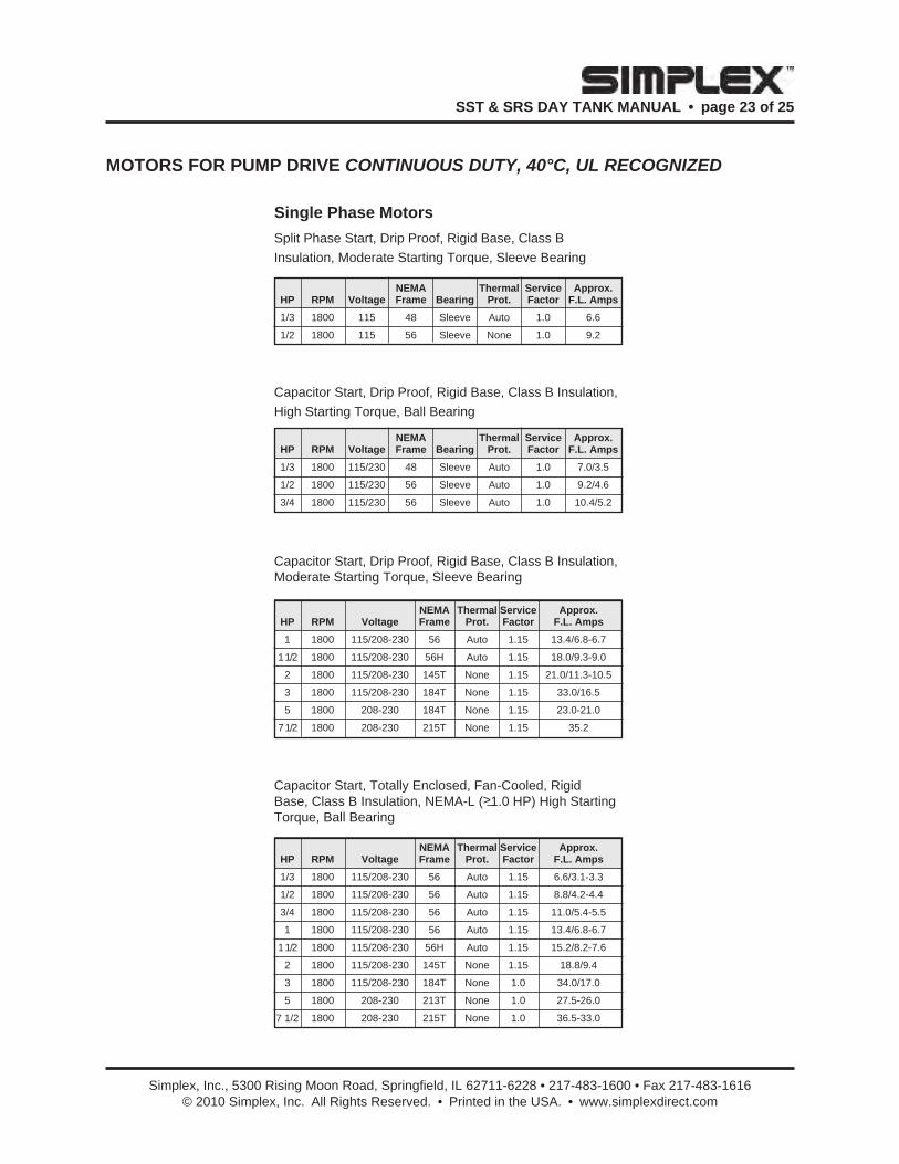
MOTORS FOR PUMP DRIVE CONTINUOUS DUTY, 40°C, UL RECOGNIZED
Single Phase Motors
Split Phase Start, Drip Proof, Rigid Base, Class B
Insulation, Moderate Starting Torque, Sleeve Bearing
NEMA Thermal Service Approx. HP RPM Voltage Frame Bearing Prot. Factor F.L. Amps
1/3 1800 115 48 Sleeve Auto 1.0 6.6
1/2 1800 115 56 Sleeve None 1.0 9.2
NEMA Thermal Service Approx. HP RPM Voltage Frame Bearing Prot. Factor F.L. Amps
1/3 1800 115/230 48 Sleeve Auto 1.0 7.0/3.5
1/2 1800 115/230 56 Sleeve Auto 1.0 9.2/4.6
3/4 1800 115/230 56 Sleeve Auto 1.0 10.4/5.2
Capacitor Start, Drip Proof, Rigid Base, Class B Insulation, Moderate Starting Torque, Sleeve Bearing
NEMA Thermal Service Approx. HP RPM Voltage Frame Prot. Factor F.L. Amps
1 1800 115/208-230 56 Auto 1.15 13.4/6.8-6.7
1 1/2 1800 115/208-230 56H Auto 1.15 18.0/9.3-9.0
2 1800 115/208-230 145T None 1.15 21.0/11.3-10.5
3 1800 115/208-230 184T None 1.15 33.0/16.5
5 1800 208-230 184T None 1.15 23.0-21.0
7 1/2 1800 208-230 215T None 1.15 35.2
Capacitor Start, Drip Proof, Rigid Base, Class B Insulation,
High Starting Torque, Ball Bearing
NEMA Thermal Service Approx. HP RPM Voltage Frame Prot. Factor F.L. Amps
1/3 1800 115/208-230 56 Auto 1.15 6.6/3.1-3.3
1/2 1800 115/208-230 56 Auto 1.15 8.8/4.2-4.4
3/4 1800 115/208-230 56 Auto 1.15 11.0/5.4-5.5
1 1800 115/208-230 56 Auto 1.15 13.4/6.8-6.7
1 1/2 1800 115/208-230 56H Auto 1.15 15.2/8.2-7.6
2 1800 115/208-230 145T None 1.15 18.8/9.4
3 1800 115/208-230 184T None 1.0 34.0/17.0
5 1800 208-230 213T None 1.0 27.5-26.0
7 1/2 1800 208-230 215T None 1.0 36.5-33.0
Capacitor Start, Totally Enclosed, Fan-Cooled, Rigid Base, Class B Insulation, NEMA-L (>1.0 HP) High Starting Torque, Ball Bearing
Simplex, Inc., 5300 Rising Moon Road, Springfi eld, IL 62711-6228 • 217-483-1600 • Fax 217-483-1616© 2010 Simplex, Inc. All Rights Reserved. • Printed in the USA. • www.simplexdirect.com
SST & SRS DAY TANK MANUAL • page 24 of 25
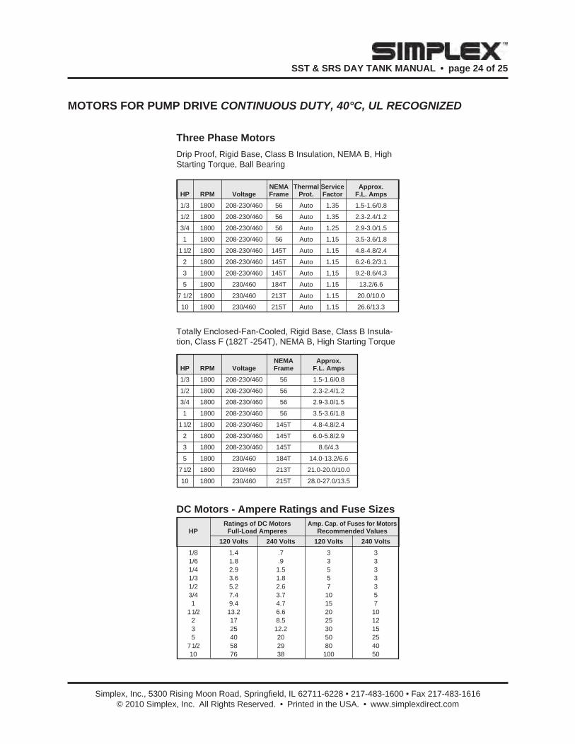
MOTORS FOR PUMP DRIVE CONTINUOUS DUTY, 40°C, UL RECOGNIZED
Three Phase Motors
Drip Proof, Rigid Base, Class B Insulation, NEMA B, High Starting Torque, Ball Bearing
NEMA Thermal Service Approx. HP RPM Voltage Frame Prot. Factor F.L. Amps
1/3 1800 208-230/460 56 Auto 1.35 1.5-1.6/0.8
1/2 1800 208-230/460 56 Auto 1.35 2.3-2.4/1.2
3/4 1800 208-230/460 56 Auto 1.25 2.9-3.0/1.5
1 1800 208-230/460 56 Auto 1.15 3.5-3.6/1.8
1 1/2 1800 208-230/460 145T Auto 1.15 4.8-4.8/2.4
2 1800 208-230/460 145T Auto 1.15 6.2-6.2/3.1
3 1800 208-230/460 145T Auto 1.15 9.2-8.6/4.3
5 1800 230/460 184T Auto 1.15 13.2/6.6
7 1/2 1800 230/460 213T Auto 1.15 20.0/10.0
10 1800 230/460 215T Auto 1.15 26.6/13.3
Totally Enclosed-Fan-Cooled, Rigid Base, Class B Insula-tion, Class F (182T -254T), NEMA B, High Starting Torque
NEMA Approx. HP RPM Voltage Frame F.L. Amps
1/3 1800 208-230/460 56 1.5-1.6/0.8
1/2 1800 208-230/460 56 2.3-2.4/1.2
3/4 1800 208-230/460 56 2.9-3.0/1.5
1 1800 208-230/460 56 3.5-3.6/1.8
1 1/2 1800 208-230/460 145T 4.8-4.8/2.4
2 1800 208-230/460 145T 6.0-5.8/2.9
3 1800 208-230/460 145T 8.6/4.3
5 1800 230/460 184T 14.0-13.2/6.6
7 1/2 1800 230/460 213T 21.0-20.0/10.0
10 1800 230/460 215T 28.0-27.0/13.5
DC Motors - Ampere Ratings and Fuse Sizes Ratings of DC Motors Amp. Cap. of Fuses for Motors HP Full-Load Amperes Recommended Values
120 Volts 240 Volts 120 Volts 240 Volts
1/8 1.4 .7 3 3 1/6 1.8 .9 3 3 1/4 2.9 1.5 5 3 1/3 3.6 1.8 5 3 1/2 5.2 2.6 7 3 3/4 7.4 3.7 10 5 1 9.4 4.7 15 7 1 1/2 13.2 6.6 20 10 2 17 8.5 25 12 3 25 12.2 30 15 5 40 20 50 25 7 1/2 58 29 80 40 10 76 38 100 50
Simplex, Inc., 5300 Rising Moon Road, Springfi eld, IL 62711-6228 • 217-483-1600 • Fax 217-483-1616© 2010 Simplex, Inc. All Rights Reserved. • Printed in the USA. • www.simplexdirect.com
SST & SRS DAY TANK MANUAL • page 25 of 25
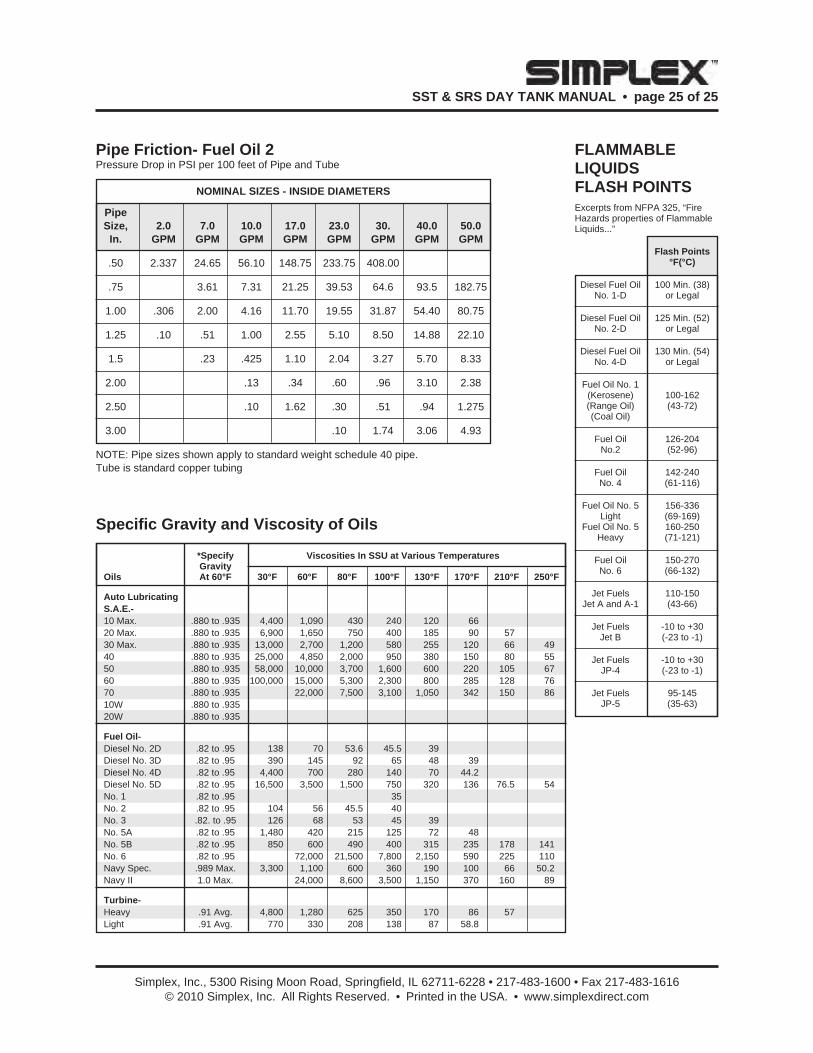
FLAMMABLE LIQUIDSFLASH POINTSExcerpts from NFPA 325, “Fire Hazards properties of Flammable Liquids...”
Specifi c Gravity and Viscosity of Oils
*Specify Viscosities In SSU at Various Temperatures Gravity Oils At 60°F 30°F 60°F 80°F 100°F 130°F 170°F 210°F 250°F
Auto Lubricating S.A.E.- 10 Max. .880 to .935 4,400 1,090 430 240 120 66 20 Max. .880 to .935 6,900 1,650 750 400 185 90 57 30 Max. .880 to .935 13,000 2,700 1,200 580 255 120 66 49 40 .880 to .935 25,000 4,850 2,000 950 380 150 80 55 50 .880 to .935 58,000 10,000 3,700 1,600 600 220 105 67 60 .880 to .935 100,000 15,000 5,300 2,300 800 285 128 76 70 .880 to .935 22,000 7,500 3,100 1,050 342 150 86 10W .880 to .935 20W .880 to .935
Fuel Oil- Diesel No. 2D .82 to .95 138 70 53.6 45.5 39 Diesel No. 3D .82 to .95 390 145 92 65 48 39 Diesel No. 4D .82 to .95 4,400 700 280 140 70 44.2 Diesel No. 5D .82 to .95 16,500 3,500 1,500 750 320 136 76.5 54 No. 1 .82 to .95 35 No. 2 .82 to .95 104 56 45.5 40 No. 3 .82. to .95 126 68 53 45 39 No. 5A .82 to .95 1,480 420 215 125 72 48 No. 5B .82 to .95 850 600 490 400 315 235 178 141 No. 6 .82 to .95 72,000 21,500 7,800 2,150 590 225 110 Navy Spec. .989 Max. 3,300 1,100 600 360 190 100 66 50.2 Navy II 1.0 Max. 24,000 8,600 3,500 1,150 370 160 89
Turbine- Heavy .91 Avg. 4,800 1,280 625 350 170 86 57 Light .91 Avg. 770 330 208 138 87 58.8
Flash Points °F(°C)
Diesel Fuel Oil 100 Min. (38) No. 1-D or Legal
Diesel Fuel Oil 125 Min. (52) No. 2-D or Legal
Diesel Fuel Oil 130 Min. (54) No. 4-D or Legal
Fuel Oil No. 1 (Kerosene) 100-162 (Range Oil) (43-72) (Coal Oil)
Fuel Oil 126-204 No.2 (52-96)
Fuel Oil 142-240 No. 4 (61-116)
Fuel Oil No. 5 156-336 Light (69-169) Fuel Oil No. 5 160-250 Heavy (71-121)
Fuel Oil 150-270 No. 6 (66-132)
Jet Fuels 110-150 Jet A and A-1 (43-66)
Jet Fuels -10 to +30 Jet B (-23 to -1)
Jet Fuels -10 to +30 JP-4 (-23 to -1)
Jet Fuels 95-145 JP-5 (35-63)
Pipe Friction- Fuel Oil 2Pressure Drop in PSI per 100 feet of Pipe and Tube
NOMINAL SIZES - INSIDE DIAMETERS
Pipe Size, 2.0 7.0 10.0 17.0 23.0 30. 40.0 50.0 In. GPM GPM GPM GPM GPM GPM GPM GPM
.50 2.337 24.65 56.10 148.75 233.75 408.00
.75 3.61 7.31 21.25 39.53 64.6 93.5 182.75
1.00 .306 2.00 4.16 11.70 19.55 31.87 54.40 80.75
1.25 .10 .51 1.00 2.55 5.10 8.50 14.88 22.10
1.5 .23 .425 1.10 2.04 3.27 5.70 8.33
2.00 .13 .34 .60 .96 3.10 2.38
2.50 .10 1.62 .30 .51 .94 1.275
3.00 .10 1.74 3.06 4.93
NOTE: Pipe sizes shown apply to standard weight schedule 40 pipe. Tube is standard copper tubing


![A Dimensions: [mm] B Recommended land pattern: [mm] · 2020. 8. 11. · 2014-03-11 2013-12-19 2013-12-04 2013-04-10 2013-03-06 2013-02-14 2012-12-10 DATE SSt SSt SSt SSt SSt SSt SSt](https://img.pdfslide.us/doc/110x75/6145e75a8f9ff812541fec6f/a-dimensions-mm-b-recommended-land-pattern-mm-2020-8-11-2014-03-11-2013-12-19.jpg)