Embed Size (px)
Citation preview
1
TRANSFORMER
• A transformer is a static device.• The word ‘transformer’ comes form the word
‘transform’.• Transformer is not an energy conversion device, but
it is device that changes AC electrical power at one voltage level into AC electrical power at another voltage level through the action of magnetic field but with a proportional increase or decrease in the current ratings., without a change in frequency.
• It can be either to step-up or step down.
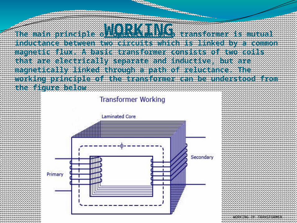
The main principle of operation of a transformer is mutual inductance between two circuits which is linked by a common magnetic flux. A basic transformer consists of two coils that are electrically separate and inductive, but are magnetically linked through a path of reluctance. The working principle of the transformer can be understood from the figure below
WORKING OF TRANSFORMER
WORKING
As shown above the transformer has primary and secondary windings. The core laminations are joined in the form of strips in between the strips you can see that there are some narrow gaps right through the cross-section of the core. These staggered joints are said to be ‘imbricated’. Both the coils have high mutual inductance. A mutual electro-motive force is induced in the transformer from the alternating flux that is set up in the laminated core, due to the coil that is connected to a source of alternating voltage. Most of the alternating flux developed by this coil is linked with the other coil and thus produces the mutual induced electro-motive force. The so produced electro-motive force can be explained with the help of Faraday’s laws of Electromagnetic Induction ase=M*dI/dtIf the second coil circuit is closed, a current flows in it and thus electrical energy is transferred magnetically from the first to the second coil.The alternating current supply is given to the first coil and hence it can be called as the primary winding. The energy is drawn out from the second coil and thus can be called as the secondary winding.
In short, a transformer carries the operations shown below:
•Transfer of electric power from one circuit to another.• Transfer of electric power without any change in frequency.•Transfer with the principle of electromagnetic induction.•The two electrical circuits are linked by mutual induction.
For the simple construction of a transformer, you must need two coils having mutual inductance and a laminated steel core. The two coils are insulated from each other and from the steel core. The device will also need some suitable container for the assembled core and
windings, a medium with which the core and its windings from its container can be insulated.
In order to insulate and to bring out the terminals of the winding from the tank, apt bushings that are made from either porcelain or capacitor type must be used.
In all transformers that are used commercially, the core is made out of transformer sheet steel laminations assembled to provide a continuous magnetic path with minimum of air-gap
included. The steel should have high permeability and low hysteresis loss. For this to happen, the steel should be made of high silicon content and must also be heat treated. By
effectively laminating the core, the eddy-current losses can be reduced. The lamination can be done with the help of a light coat of core plate varnish or lay an oxide layer on the
surface. For a frequency of 50 Hertz, the thickness of the lamination varies from 0.35mm to 0.5mma frequency of 25 Hertz.
Transformer Construction
Classification of transformer
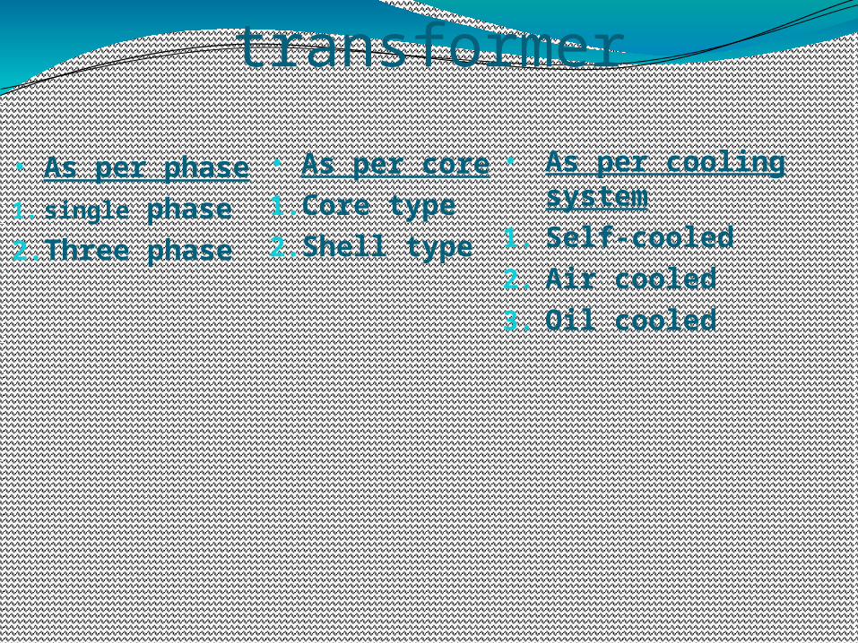
• As per phase1. single phase2.Three phase
• As per core1.Core type2.Shell type
• As per cooling system
1. Self-cooled2. Air cooled3. Oil cooled
Transformer classified as per core
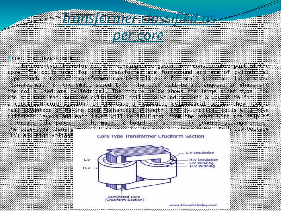
CORE TYPE TRANSFORMER:-
In core-type transformer, the windings are given to a considerable part of the core. The coils used for this transformer are form-wound and are of cylindrical type. Such a type of transformer can be applicable for small sized and large sized transformers. In the small sized type, the core will be rectangular in shape and the coils used are cylindrical. The figure below shows the large sized type. You can see that the round or cylindrical coils are wound in such a way as to fit over a cruciform core section. In the case of circular cylindrical coils, they have a fair advantage of having good mechanical strength. The cylindrical coils will have different layers and each layer will be insulated from the other with the help of materials like paper, cloth, macerate board and so on. The general arrangement of the core-type transformer with respect to the core is shown below. Both low-voltage (LV) and high voltage (HV) windings are shown.
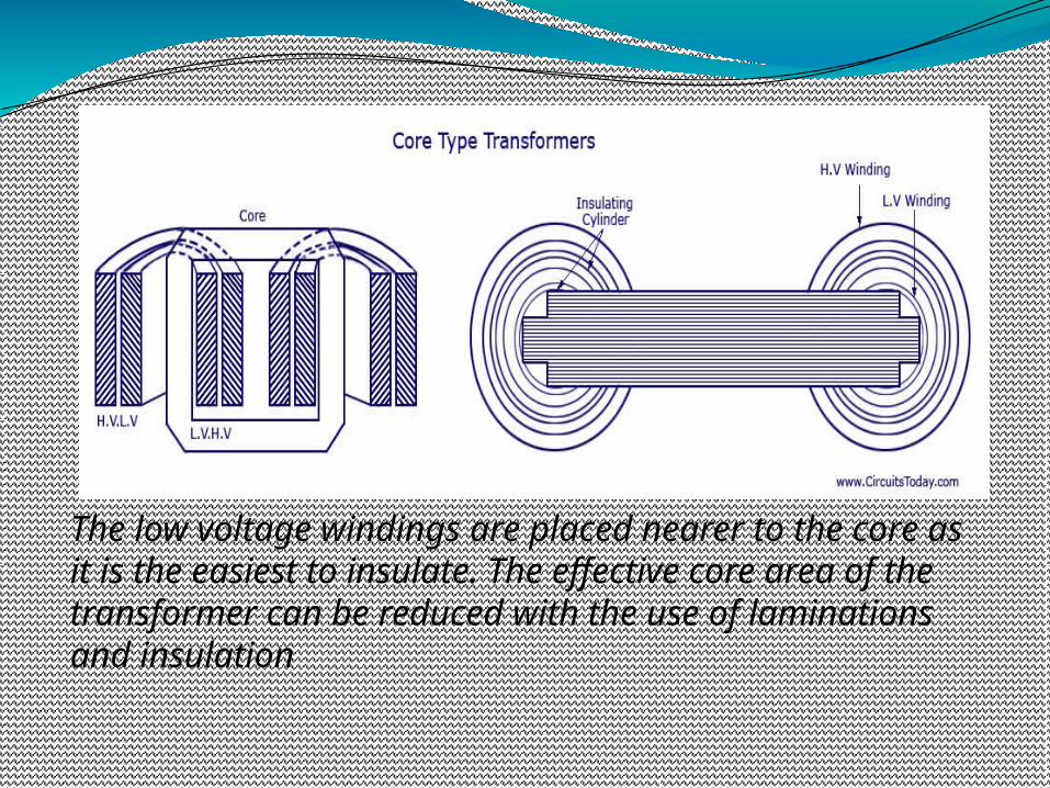
The low voltage windings are placed nearer to the core as it is the easiest to insulate. The effective core area of the transformer can be reduced with the use of laminations and insulation
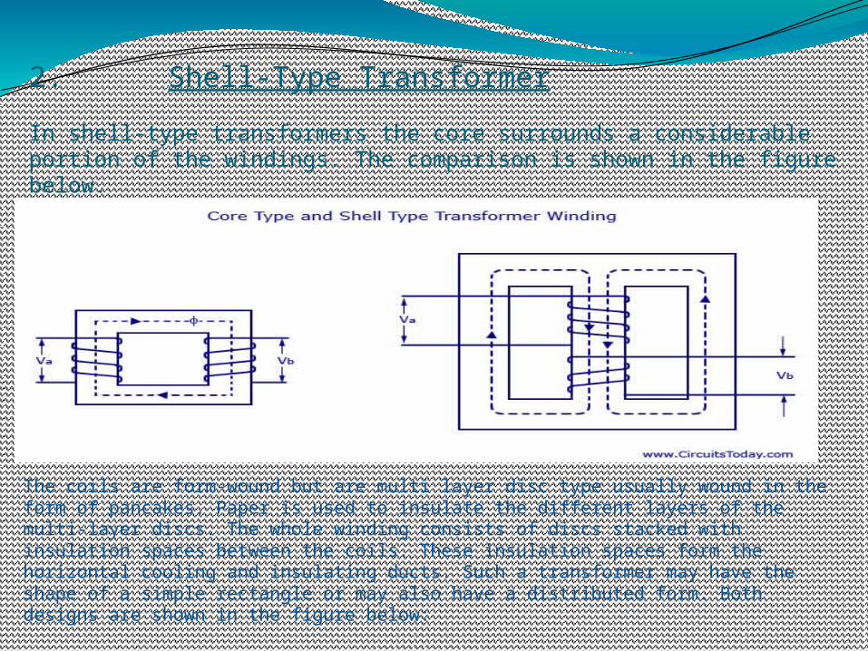
2. Shell-Type Transformer
In shell-type transformers the core surrounds a considerable portion of the windings. The comparison is shown in the figure below.
The coils are form-wound but are multi layer disc type usually wound in the form of pancakes. Paper is used to insulate the different layers of the multi-layer discs. The whole winding consists of discs stacked with insulation spaces between the coils. These insulation spaces form the horizontal cooling and insulating ducts. Such a transformer may have the shape of a simple rectangle or may also have a distributed form. Both designs are shown in the figure below:
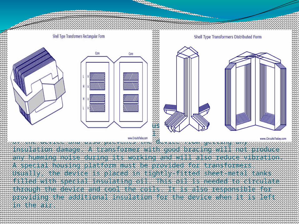
A strong rigid mechanical bracing must be given to the cores and coils of the transformers. This will help in minimizing the movement of the device and also prevents the device from getting any insulation damage. A transformer with good bracing will not produce any humming noise during its working and will also reduce vibration.A special housing platform must be provided for transformers. Usually, the device is placed in tightly-fitted sheet-metal tanks filled with special insulating oil. This oil is needed to circulate through the device and cool the coils. It is also responsible for providing the additional insulation for the device when it is left in the air.
CLASSIFICATION ON THE BASIS OF COOLING EMPLOYED
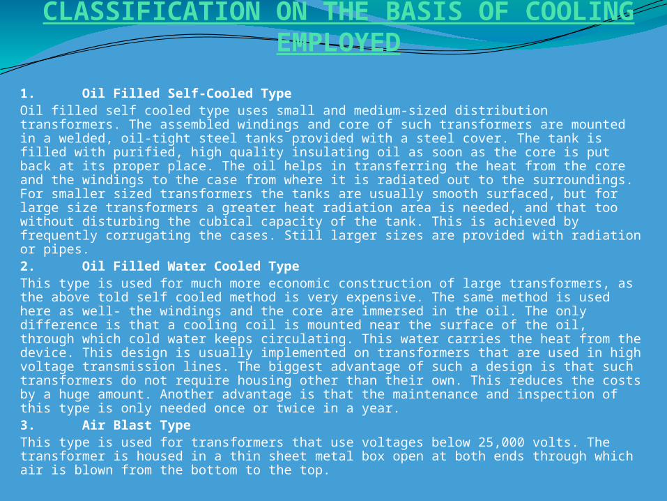
1. Oil Filled Self-Cooled TypeOil filled self cooled type uses small and medium-sized distribution transformers. The assembled windings and core of such transformers are mounted in a welded, oil-tight steel tanks provided with a steel cover. The tank is filled with purified, high quality insulating oil as soon as the core is put back at its proper place. The oil helps in transferring the heat from the core and the windings to the case from where it is radiated out to the surroundings. For smaller sized transformers the tanks are usually smooth surfaced, but for large size transformers a greater heat radiation area is needed, and that too without disturbing the cubical capacity of the tank. This is achieved by frequently corrugating the cases. Still larger sizes are provided with radiation or pipes.2. Oil Filled Water Cooled TypeThis type is used for much more economic construction of large transformers, as the above told self cooled method is very expensive. The same method is used here as well- the windings and the core are immersed in the oil. The only difference is that a cooling coil is mounted near the surface of the oil, through which cold water keeps circulating. This water carries the heat from the device. This design is usually implemented on transformers that are used in high voltage transmission lines. The biggest advantage of such a design is that such transformers do not require housing other than their own. This reduces the costs by a huge amount. Another advantage is that the maintenance and inspection of this type is only needed once or twice in a year.3. Air Blast TypeThis type is used for transformers that use voltages below 25,000 volts. The transformer is housed in a thin sheet metal box open at both ends through which air is blown from the bottom to the top.
Three phase transformer
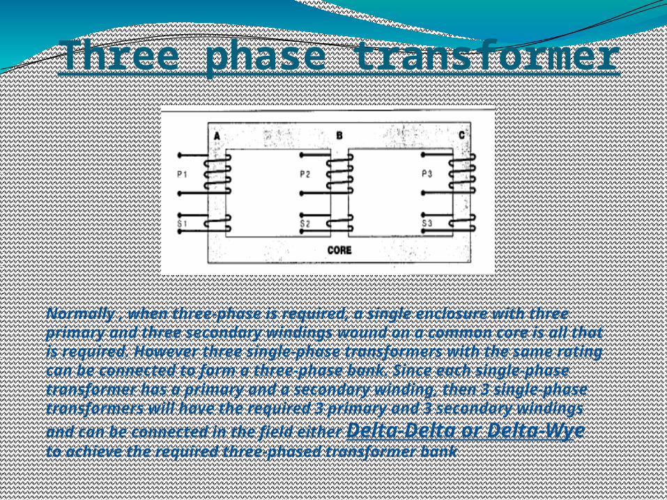
Normally , when three-phase is required, a single enclosure with three primary and three secondary windings wound on a common core is all that is required. However three single-phase transformers with the same rating can be connected to form a three-phase bank. Since each single-phase transformer has a primary and a secondary winding, then 3 single-phase transformers will have the required 3 primary and 3 secondary windings and can
be connected in the field either Delta-Delta or Delta-Wye to achieve the required three-phased transformer bank
Ideal transformer
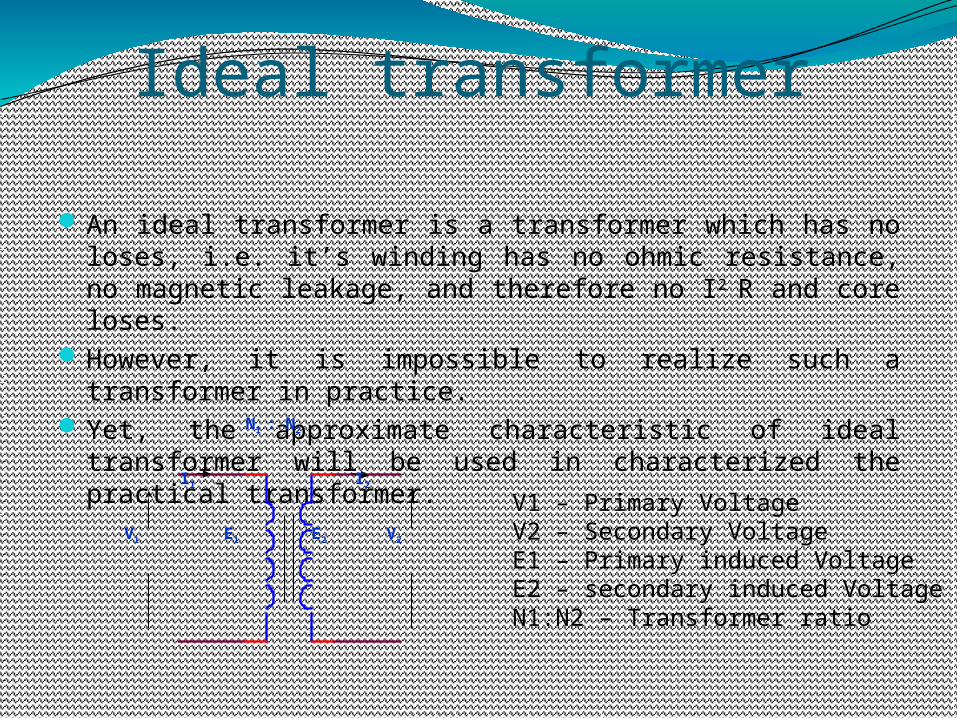
An ideal transformer is a transformer which has no loses, i.e. it’s winding has no ohmic resistance, no magnetic leakage, and therefore no I2 R and core loses.
However, it is impossible to realize such a transformer in practice.
Yet, the approximate characteristic of ideal transformer will be used in characterized the practical transformer.
V1 V2
N1 : N2
E1 E2
I1 I2
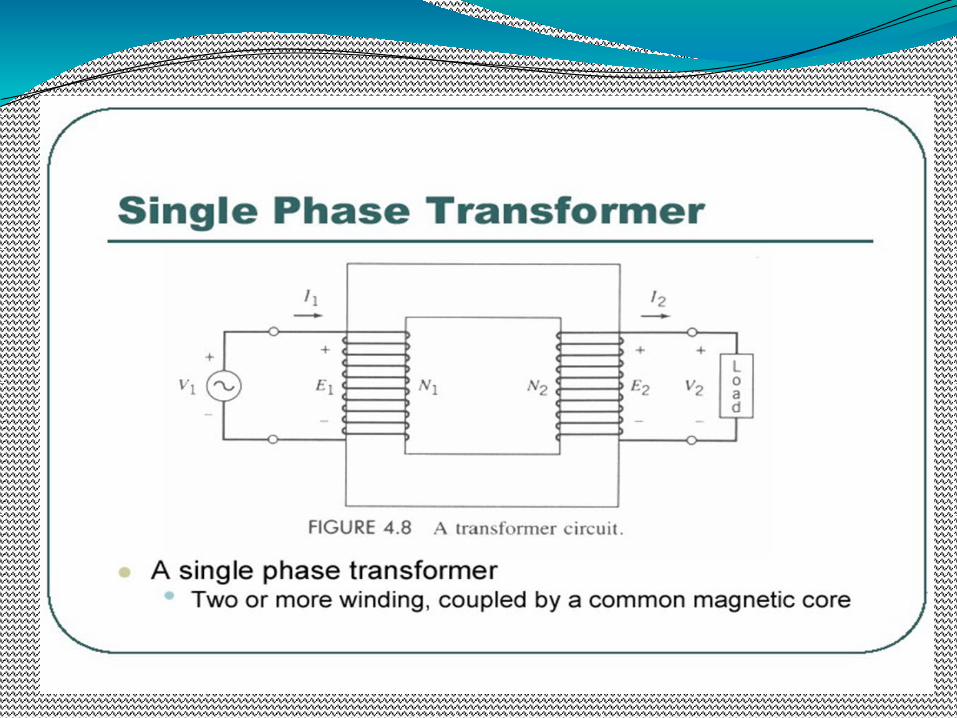
V1 – Primary VoltageV2 – Secondary VoltageE1 – Primary induced VoltageE2 – secondary induced VoltageN1:N2 – Transformer ratio
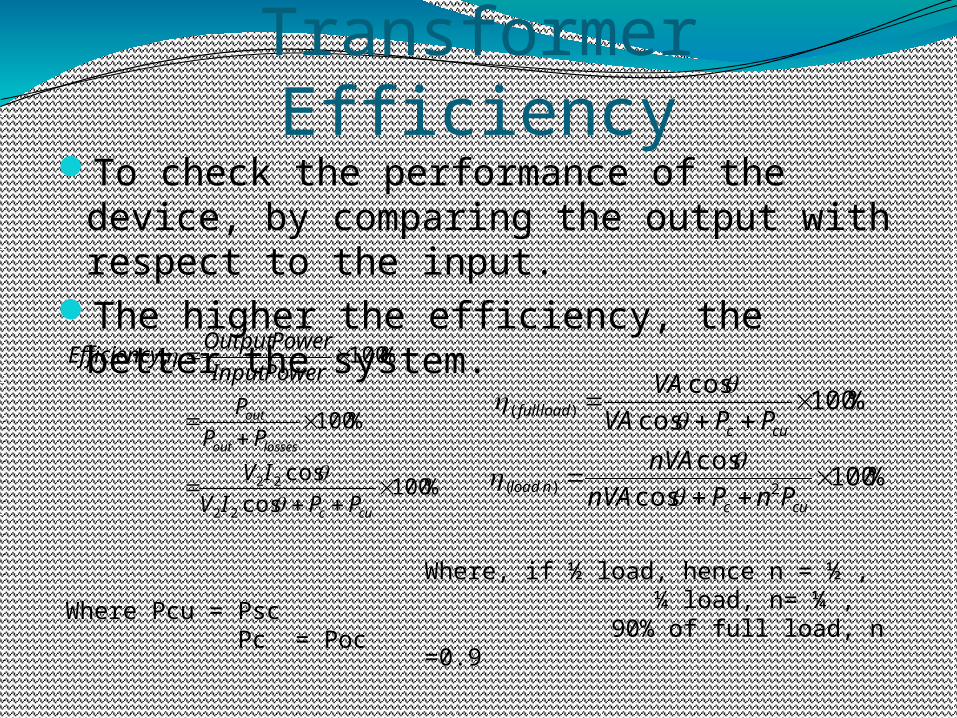
Transformer EfficiencyTo check the performance of the device, by
comparing the output with respect to the input.
The higher the efficiency, the better the system.
%100cos
cos
%100
%100,
22
22
cuc
lossesout
out
PPIV
IV
PP
P
PowerInput
PowerOutputEfficiency
%100cos
cos
%100cos
cos
2)(
)(
cucnload
cucloadfull
PnPnVA
nVA
PPVA
VA
Where, if ½ load, hence n = ½ , ¼ load, n= ¼ , 90% of full load, n =0.9
Where Pcu = Psc Pc = Poc
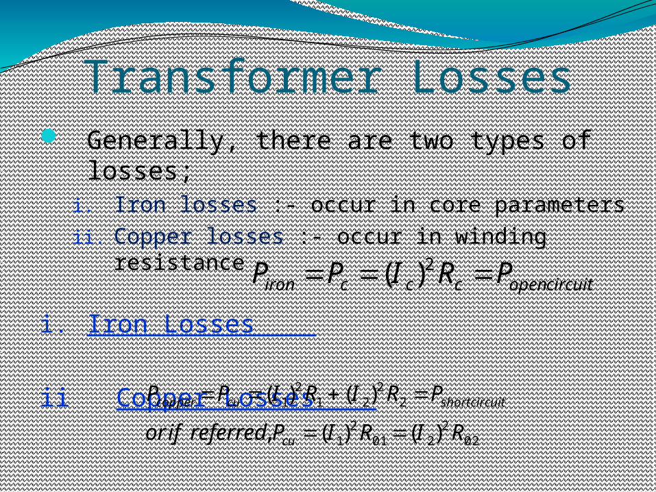
Transformer Losses Generally, there are two types of losses;
i. Iron losses :- occur in core parametersii. Copper losses :- occur in winding resistance
i. Iron Losses
ii Copper Losses
circuitopenccciron PRIPP 2)(
022
2012
1
22
212
1
)()(,
)()(
RIRIPreferredifor
PRIRIPP
cu
circuitshortcucopper

THANKYOUBYE
04/18/23
INTERNATIONAL SCHOOL NPS GUWAHATI
PHYSICS INVESTIGATORY PROJECT TOPIC:- TRANSFORMER NAME :- KISHOREDEEP TAMULI CLASS :- XII-C ROLL NO :-
04/18/23
INDEX 1.CERTIFICATE OF EXCELLENCE 2. ACKNOWLEDGEMENT 3. AIM OF PROJECT 4. INTRODUCTION 5. THEORY 6. APPARATUS REQUIRED 7. PROCEDURE FOLLOWED 8. OBSERVATION 9. PRECAUTION 10. CONCLUSION 11. BIBLIOGRAPHY
04/18/23
CertificateThis is to certify that KISHOREDEEP TAMULI , a student of class XII-C has successfully completed the Research on the below mentioned project under the guidance of during year 2015-16 in partial fulfillment of physics practical examination conducted by CBSE, New Delhi.

04/18/23
Acknowledgement In the accomplishment of this project successfully , many have best owned upon me their blessings and the heart pledged support , this time I am utilizing to thank all the people who have been concerned with project. Primarily I would thank god for being able to complete this project with success. Then I would like to thank my Principal ......and physics teacher , whose valuable guidance has been the once that helped me patch this project and make it full proof success his suggestions and his introductions has served as the major contributor towards the completion of the project. Then I would like to thank my parents and friends who have helped me with their valuable suggestions and guidance has been helpful in various phases of the completion of the project. Last but not the least I would like to thank my classmates who have helped me a lot..