Embed Size (px)
Citation preview

500-SHEET FINISHER(Machine Code: G302/B442)

10 August, 2001 EXTERIOR
B442-1
Opt
ions
1. REPLACEMENT AND ADJUSTMENT1.1 EXTERIORNOTE: This manual uses several symbols. The meanings for these symbols are
as follows:☛: See or refer to !: screw ": connector #: clip
Front cover[A]: : Front cover (!1)
Rear cover[A]: Rear cover (!1)
B442R101.WMF
B442R102.WMF
[A]
[A]

EXTERIOR 10 August, 2001
B442-2
Top cover[A]: Top cover (2 links)
Front lower guide
[A]: Output tray (#2)[B]: Front lower guide (!2)
NOTE: 1) When re-attaching the lower guide, be sure that it is not in contact withthe exit lower guide and that the exit lower guide moves smoothly.
2) Make sure that the blue and black cables are in the correct position, asengraved on the inside of the front lower guide.
B442R105.WMF
B442R104.WMF
B442R116.WMF
[A]
[A]
[B]

10 August, 2001 EXTERIOR
B442-3
Opt
ions
Right cover[A]: Grounding plate (!1)[B]: Right cover (!2)
B442R103.WMF[A]
[B]

ENTRANCE UPPER GUIDE / PAPER EXIT UNIT 10 August, 2001
B442-4
1.2 ENTRANCE UPPER GUIDE / PAPER EXIT UNIT
• Front, rear, and top covers and front lower guide (☛ 1.1 Exterior)[A]: Entrance upper guide (!2, "1)[B]: Paddle gear spring[C]: Paddle gear (#1)[D]: Paddle gear holder[E]: Bushing (#1)[F]: Paper exit unit holder (!1)[G]: Rear paper exit unit holder (!1)[H]: Exit unit
NOTE: Keep the paper exit unit stays inthe upper position. Rotate thepaddle roller into the positionshown in the illustration [a]. Then,insert the paddle gear, makingsure that the pawl on the gear’souter frame is resting on the clutchlink [b].
B442R106.WMF
B442R107.WMF
[A]
[B]
[C]
[D]
[E]
[F]
[G]
[H]
[a]
[b]
10 August, 2001 ENTRANCE LOWER GUIDE
B442-5
Opt
ions
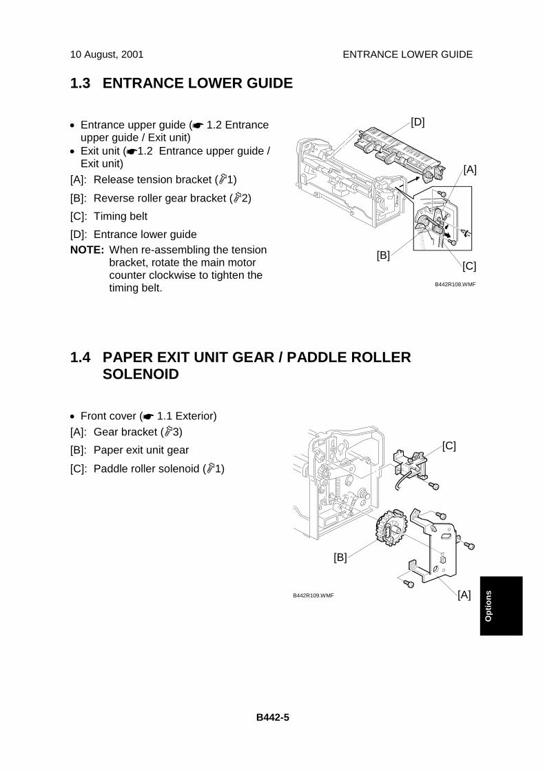
1.3 ENTRANCE LOWER GUIDE
• Entrance upper guide (☛ 1.2 Entranceupper guide / Exit unit)
• Exit unit (☛1.2 Entrance upper guide /Exit unit)
[A]: Release tension bracket (!1)[B]: Reverse roller gear bracket (!2)[C]: Timing belt[D]: Entrance lower guideNOTE: When re-assembling the tension
bracket, rotate the main motorcounter clockwise to tighten thetiming belt.
1.4 PAPER EXIT UNIT GEAR / PADDLE ROLLERSOLENOID
• Front cover (☛ 1.1 Exterior)[A]: Gear bracket (!3)[B]: Paper exit unit gear[C]: Paddle roller solenoid (!1)
B442R108.WMF
B442R109.WMF [A]
[B]
[C]
[A]
[B][C]
[D]

STAPLER UNIT 10 August, 2001
B442-6
1.5 STAPLER UNIT• Rear cover (☛1.1 Exterior)[A]: Stapler unit bracket (!2, "1)[B]: Stapler unit (!3)
1.6 JOGGER TRAY UNIT• Entrance upper guide and paper exit unit
(☛1.2 Entrance upper guide / paper exitunit)
• Entrance lower guide (☛1.2 Entrancelower guide)
• Paper exit unit gear and Paddle rollersolenoid (☛1.4 Paper exit unit gear /Paddle roller solenoid)
• Stapler unit (☛ 1.5 Stapler unit)[A]: Jogger tray unit holders (!2)[B]: Jogger tray unit (!1, "3)NOTE: Be sure to connect the black cable
to the paper exit sensor and theblue one to the jogger homeposition sensor.
B442R115.WMF
B442R110.WMF
[A]
[B]
[A]
[B]

10 August, 2001 PAPER EXIT SENSOR FEELER
B442-7
Opt
ions
1.7 PAPER EXIT SENSOR FEELER• Jogger tray unit (☛1.6 Jogger tray unit)• Jogger motor (☛1.9 Jogger motor)[A]: Paper exit sensor feeler
1.8 MAIN MOTOR• Right cover (☛1.1 Exterior)[A]: Release tension bracket (!1)[B]: Main motor (!2, "1)
B442R121.WMF
B442R113.WMF
[A]
[A]
[B]

JOGGER MOTOR 10 August, 2001
B442-8
1.9 JOGGER MOTOR
• Front lower guide (☛1.1 Exterior)[A]: Jogger motor (!2, "3)
1.10 CONTROL BOARD
• Front lower guide (☛1.1 Exterior)[A]: Control board (!1, "12)
B442R114.WMF
B442R112.WMF
[A]
[A]

10 August, 2001 OUTPUT TRAY UNIT
B442-9
Opt
ions
1.11 OUTPUT TRAY UNIT
[A]: Output tray cover (!2)[B]: Tray holder (!1)[C]: Links[D]: Connector cover[E]: Output tray motor link unit (!1)[F]: Rear cover (!1)[G]: Output tray motor ("1)
NOTE: When re-attaching the motor linkunit, the arrows on each of thegears need to face each other asshown in the illustration.
B442R117.WMF B442R118.WMF
B442R119.WMF
B442R120.WMF
[A]
[B] [C]
[D]
[E]
[F]
[G]

OVERALL MACHINE INFORMATION 10 August, 2001
B442-10
2. DETAILED DESCRIPTIONS2.1 OVERALL MACHINE INFORMATION2.1.1 COMPONENT LAYOUT
Mechanical component layout
1. Output tray2. Stack height detection lever3. Paper exit roller4. Jogger tray5. Reverse roller
6. Lower entrance guide7. Upper entrance guide8. Paper exit unit9. Paddle roller10. Lower exit guide
B442D101.WMF
1
2 3
10
4
6
7
89
5

10 August, 2001 OVERALL MACHINE INFORMATION
B442-11
Opt
ions
Drive layout
1. Main motor2. Exit roller timing belt3. Main motor timing belt4. Output tray motor
5. Output tray link gears6. Paper exit unit drive gear7. Reverse roller8. Paper exit roller
B442D103.WMF
2
3
1
65
4
8
7
OVERALL MACHINE INFORMATION 10 August, 2001
B442-12
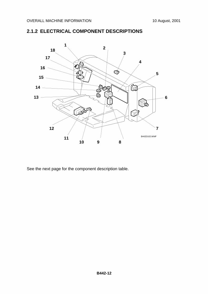
2.1.2 ELECTRICAL COMPONENT DESCRIPTIONS
See the next page for the component description table.
B442D102.WMF
18
17
15
14
13
1110
12
9
7
6
5
4
32
8
1
16
10 August, 2001 OVERALL MACHINE INFORMATION
B442-13
Opt
ions
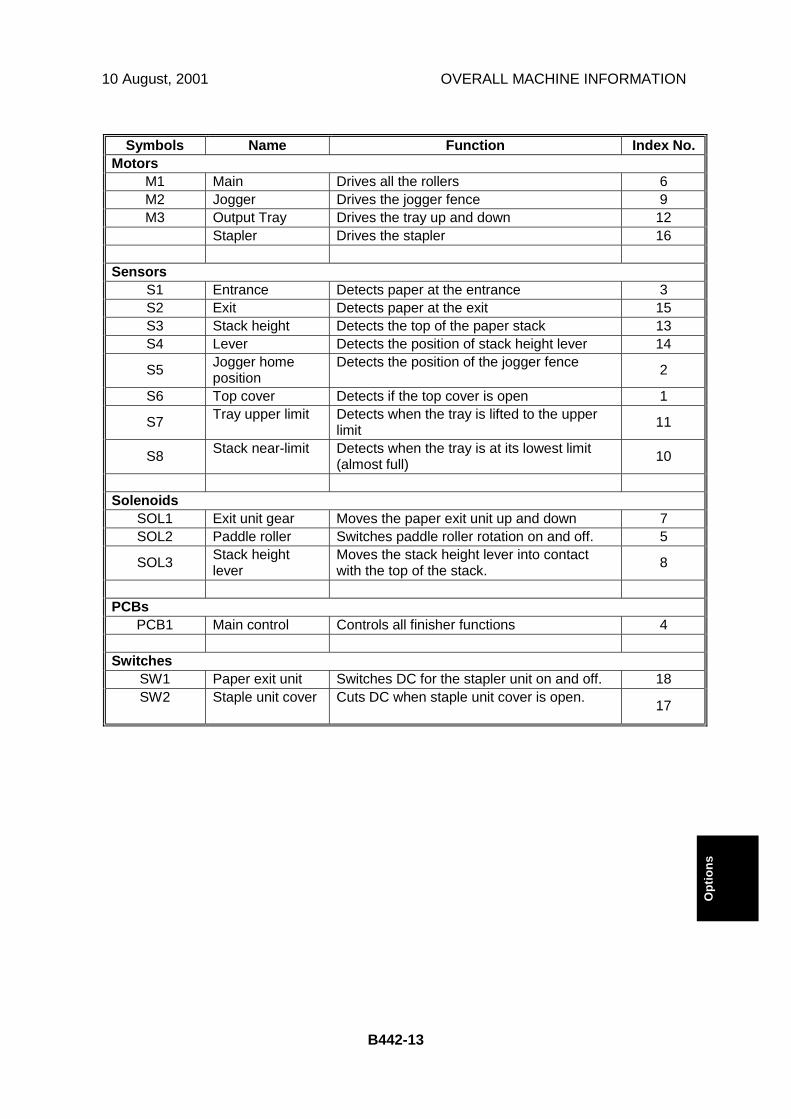
Symbols Name Function Index No.Motors
M1 Main Drives all the rollers 6M2 Jogger Drives the jogger fence 9M3 Output Tray Drives the tray up and down 12
Stapler Drives the stapler 16
SensorsS1 Entrance Detects paper at the entrance 3S2 Exit Detects paper at the exit 15S3 Stack height Detects the top of the paper stack 13S4 Lever Detects the position of stack height lever 14
S5 Jogger homeposition
Detects the position of the jogger fence 2
S6 Top cover Detects if the top cover is open 1
S7 Tray upper limit Detects when the tray is lifted to the upperlimit 11
S8 Stack near-limit Detects when the tray is at its lowest limit(almost full) 10
SolenoidsSOL1 Exit unit gear Moves the paper exit unit up and down 7SOL2 Paddle roller Switches paddle roller rotation on and off. 5
SOL3 Stack heightlever
Moves the stack height lever into contactwith the top of the stack. 8
PCBsPCB1 Main control Controls all finisher functions 4
SwitchesSW1 Paper exit unit Switches DC for the stapler unit on and off. 18SW2 Staple unit cover Cuts DC when staple unit cover is open. 17
DETAILED SECTION DESCRIPTIONS 10 August, 2001
B442-14
2.2 DETAILED SECTION DESCRIPTIONS2.2.1 OUTPUT TRAY MECHANISM
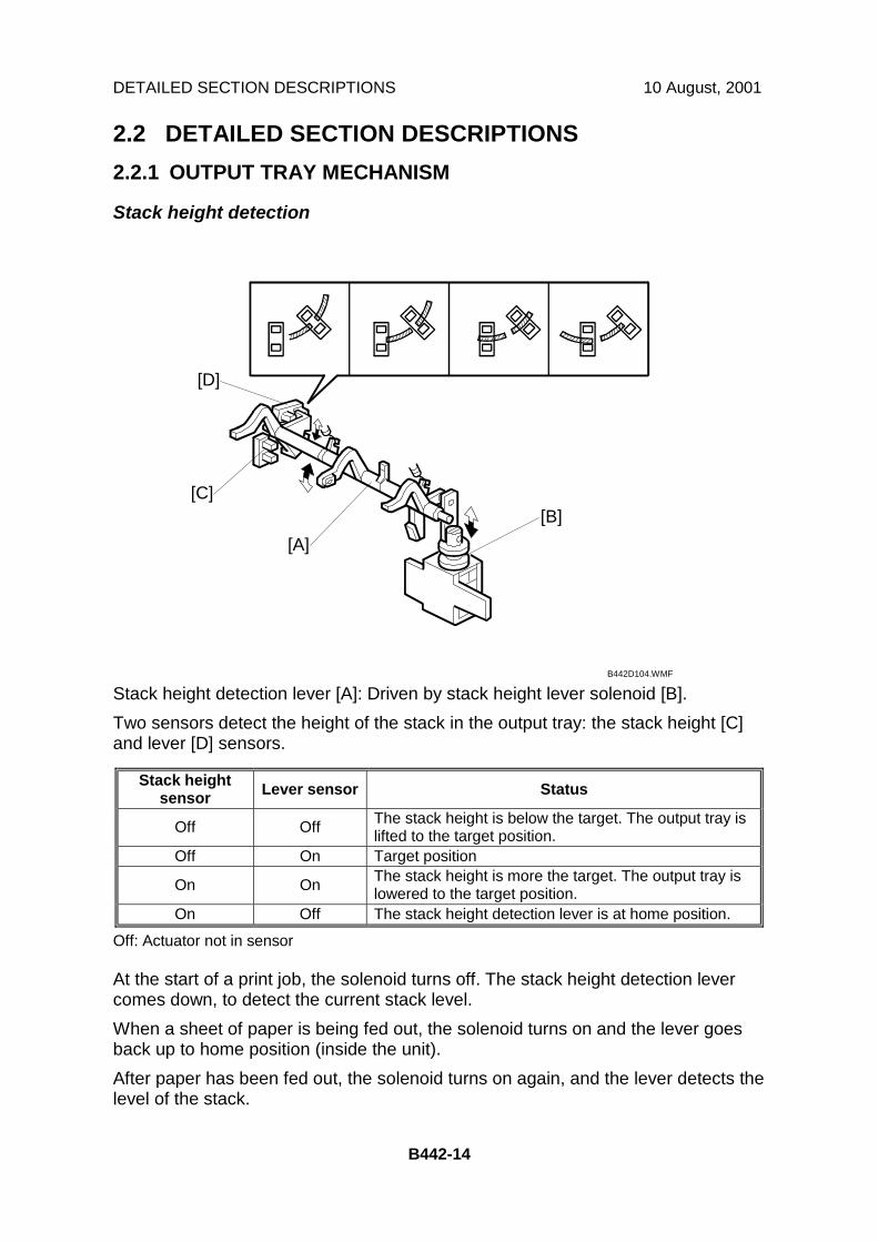
Stack height detection
Stack height detection lever [A]: Driven by stack height lever solenoid [B].Two sensors detect the height of the stack in the output tray: the stack height [C]and lever [D] sensors.
Stack heightsensor Lever sensor Status
Off Off The stack height is below the target. The output tray islifted to the target position.
Off On Target position
On On The stack height is more the target. The output tray islowered to the target position.
On Off The stack height detection lever is at home position.
Off: Actuator not in sensor
At the start of a print job, the solenoid turns off. The stack height detection levercomes down, to detect the current stack level.When a sheet of paper is being fed out, the solenoid turns on and the lever goesback up to home position (inside the unit).After paper has been fed out, the solenoid turns on again, and the lever detects thelevel of the stack.
B442D104.WMF
[A][B]
[C]
[D]

10 August, 2001 DETAILED SECTION DESCRIPTIONS
B442-15
Opt
ions
Output tray up/down mechanism
OverviewThe output tray motor [A] lifts/lowers the tray if the stack height is not at the targetposition.Gears [B] and [C] keep the angle of the tray constant at any tray position.
Output Tray Downward MovementThe top of the paper stack is checked after every page (or set of pages) has beenfed out. If the top of the stack is higher than the target level, the output tray motormoves the tray down.When the stack near-limit sensor [D] detects the actuator on gear [C], a stack near-limit signal is transferred to the main frame. The tray cannot move any lower. Thenext time the top of the stack height is above the target level, printing stops.
Output Tray Upward MovementIf paper is removed from the stack, the top of the stack will be lower than the targetlevel, and the output tray motor moves the tray up.When the tray upper limit sensor [E] detects the actuator on gear [B], the traycannot be moved up any more, so the motor stops.
B442D105.WMF
[A]
[C]
[D] [E]
[B]

DETAILED SECTION DESCRIPTIONS 10 August, 2001
B442-16
2.2.2 PAPER FEED
OverviewThe following paper feed out modes can be selected at the printer driver.
Mode DescriptionStraight feed out mode Paper is fed directly to the output tray without shifting or stapling.
Shift sorting mode Alternate sets are shifted before being fed to the output tray.Stapling mode All sets are shifted and stapled, then fed to the output tray.
Straight feed out mode
Before the job, the exit unit [A] is up, and the exit unit gear solenoid [B] is on,pulling lever [C] away from the exit unit gear [D].At the start of the job, the stack height detection lever detects the top of the stack.The tray moves up or down if the top of the stack is not at the correct level.
When the paper exit sensor in the main frame turns on, the finisher main motorstarts. It drives the exit unit gear [D] through idle gear [E]. The gear pulls paper exitunit [A] down, using the paper exit link [F]. The link also moves the paper exit roller[H] up through the exit roller drive gear [G].When the motor starts, the solenoid switches off and a spring pushes lever [C] intocontact with the exit unit gear [D].When a part of the exit unit gear without threads [I] faces the idle gear, the gearstops turning (see the left-hand diagram). The lever [C] catches a peg on the exitunit gear, to make sure that it stops at the correct position. The paper exit rollers[H] now contact each other and the main motor feeds out the paper.When the last page has been fed out, the solenoid turns on to pull the lever awayfrom the gear. The gear starts turning, to lift the exit unit to the standby position.When the other part of the exit unit gear without threads [J] faces the idle gear, theexit unit gear stops. Then, the main motor stops and the solenoid turns off.
B442D109.WMFB442D106.WMF
[A]
[C][C]
[E]
[F]
[G]
[G]
[H] [I]
[B]
[J]
[D]

10 August, 2001 DETAILED SECTION DESCRIPTIONS
B442-17
Opt
ions
Shift sorting mode
At the start of the job, and for odd numbered sets of copies, the mechanism is thesame as the straight feed out mode. However, even numbered sets are fed back tothe jogger tray, which shifts the sets to one side before feeding them out.This section describes what happens for even-numbered sets (sets 2, 4, 6 etc) ofthe job.A short time after the entrance sensor [A] detects the first page of the set, thepaper exit unit solenoid turns on to restart the rotation of the paper exit unit gear,raising the paper exit unit to the standby position. It stays there until after the lastpage of the set.The paper cannot feed out, so it drops into the jogger tray [B]. The paddle rollersolenoid [C] turns on and the paddle roller [D] feeds the paper to the reverse roller[E]. The reverse roller feeds the paper to the end fence [F] of the jogger tray.
B442D113.WMF
B442D111.WMF
[A]
[E] [F]
[B]
[D]
[C]
DETAILED SECTION DESCRIPTIONS 10 August, 2001
B442-18
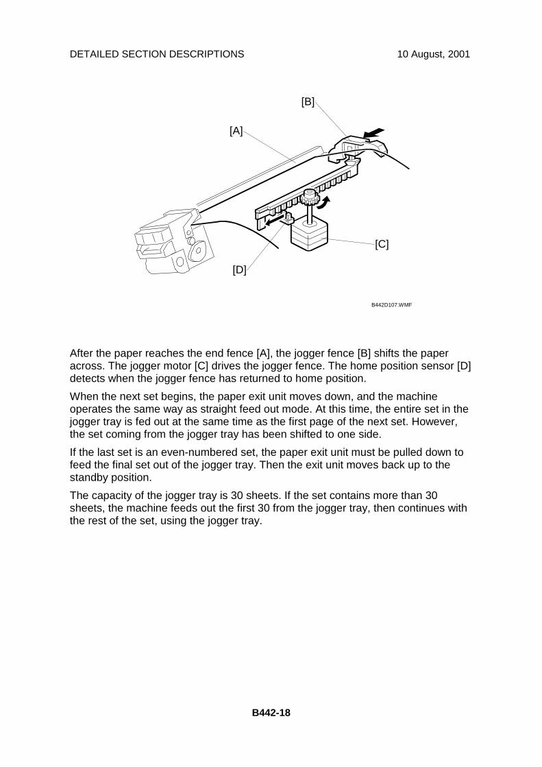
After the paper reaches the end fence [A], the jogger fence [B] shifts the paperacross. The jogger motor [C] drives the jogger fence. The home position sensor [D]detects when the jogger fence has returned to home position.When the next set begins, the paper exit unit moves down, and the machineoperates the same way as straight feed out mode. At this time, the entire set in thejogger tray is fed out at the same time as the first page of the next set. However,the set coming from the jogger tray has been shifted to one side.If the last set is an even-numbered set, the paper exit unit must be pulled down tofeed the final set out of the jogger tray. Then the exit unit moves back up to thestandby position.The capacity of the jogger tray is 30 sheets. If the set contains more than 30sheets, the machine feeds out the first 30 from the jogger tray, then continues withthe rest of the set, using the jogger tray.
B442D107.WMF
[B]
[A]
[C]
[D]

10 August, 2001 DETAILED SECTION DESCRIPTIONS
B442-19
Opt
ions
Stapling mode
The stapler is attached to the jogger tray, so all sets go to the jogger tray.After all pages of a set have entered the jogger tray and been shifted across, thepaper exit link [A] pulls the paper exit unit [B] down until knob [C] on the exit unitpushes the link lever [D] for the exit unit switch [E]. This turns on the exit unitswitch. When this switch is on, dc is supplied to the stapler unit [F] and the mainmotor is turned off.The exit unit switch is activated when the exit unit is pulled part-way down. Afterstapling the set of prints, the paper exit unit is pulled down again until the unitcomes in contact with the paper exit roller [G], and the stapled set is fed out.
B442D112.WMF
B442D114.WMF
B442D106.WMF
[B]
[C][E]
[F]
[D]
[A]
[G]
[B]

DETAILED SECTION DESCRIPTIONS 10 August, 2001
B442-20
2.2.3 JAM CONDITIONSSensors Conditions
Remaining paper detection EntranceExit
Either the entrance or exit sensor detectspaper just after the unit is initialized.
Non-feed at the entranceEntrance
The entrance sensor is not activated within acertain period after the paper exit sensordetects paper.
Jamming at the entranceEntrance
The entrance sensor is not de-activated afterpaper is fed 1.3 times the length of thepaper.
Non-feed inside the unit(Straight feed out mode only) Exit
The exit sensor is not activated within acertain period after the entrance sensordetects paper.
Jamming at the exit Exit The exit sensor is not de-activated afterpaper is fed for a certain period.
Jogger tray Exit The exit sensor is de-activated during papershifting or stapling.
2.2.4 ERROR DETECTIONConditions
Jogger motor error Jogger home position sensor does not shut off after joggermotor starts.
Jogger motor home positiondetection error
Jogger home position sensor does not turn on after papershifting.
Stapler error Stapler home position sensor (inside stapler unit) does notturn on after stapling.
Output tray upper limit error Tray upper limit sensor is activated.Output tray motor error The output tray is away from the target position for more
than 10 seconds.Stack height detection error The stack height detection lever does not return to its home
position before going to detect the stack height.
NOTE: The above errors are indicated as “Finisher jam” at the first occurrence.If the same error happens again in the next job, “finisher error” is indicated.

10 August, 2001 SPECIFICATIONS
B442-21
Opt
ions
3. OVERALL MACHINE INFORMATION3.1 SPECIFICATIONSPaper Size: A3, B4, A4, B5 sideways (Metric)
DLT, LG, LT (Inch)Paper Weight 52 ~ 128 g/m2, 14 ~ 34 lb.Staple Capacity: 20 sheets (A3, B4, DLT, LG : 80 g/m2, 20 lb)
30 sheets (A4, B5 sideways, LT : 80 g/m2, 20 lb)Stack Capacity (Maximum): 500 sheets (A4/LT or smaller: 80 g/m2, 20 lb.)
250 sheets (A3, B4, DLT and LG: 80 g/m2, 20 lb.)
Stapling Positions: 1Staple Replenishment: Cartridge (3,000 staples/cartridge)Power Source: 24 V DC, 5 V DC (from the copier/printer)Power Consumption: 48 WWeight: 8.3 kg (18.4 lbs.)Dimensions (W x D x H): 350 x 490 x 230 mm


