Embed Size (px)
Citation preview

T A Y L O RS Q U I B B
Squibb Taylor GaugeSquibb Taylor Gauge Catalog Catalog 20082008
* Materials and specifications are subject to change with out notice. Pressure ratings sub ject to change due to tem per a ture and other en vi ron men tal considerations.
ApplicationIndicates direction of flow of com pat i ble liq uids in pipe lines at work ing pressures up to 500 psig [34 Bar]. The in di-ca tor must be installed in pipe line tees.
General Information & Fea tures*The head, centershaft, support tube, bearings and vane in these in di ca tors are made of 300 Series stain less steel. Mag nets are nickel-plated Alni co, and the thread ed mount ing adapters are forged steel.
4” Dial
Model Numbers
NOTE: Torque mounting bolts to 140”/150” in./lb., [16,4Nm]
Flow Indicator
1/1/09
ISO 9001:2000 REGISTERED
10480 Shady Trail #106 • Dallas, TX 75220 • (214) 357-4591 • FAX (214) 357-5923Website www.squibbtaylor.com • E-mail [email protected]
Flow Indicator
Pipe Size Includes Item Number Part Number
2” 5305 Adapter - 2” NPT 5520-2 130050
2 1/2” 5305 Adapter - 2” NPT 5520 - 2 1/2” * 130055
3” 5305 Adapter - 2” NPT 5520-3** 130060*Requires a 2 1/2” x 2” Reducing Bushing **Requires a 3” x 2” Reducing Bushing
Item Number Part Number
5520R Dial 130046
5520-2” Flapper Only 130065
5520-2 1/2” Flapper Only 130070
5520-3” Flapper Only 130075
Part Numbers
www.squibbtaylor.comSee reverse side for dimensional data, materials of construction, performance, and advice on how to order.
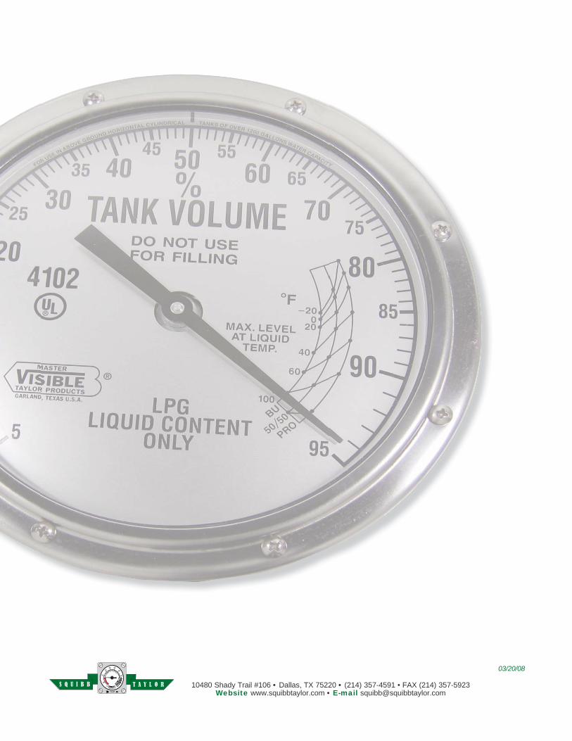
Master Visible Liquid-Level GaugesMaster Visible Liquid-Level Gauges
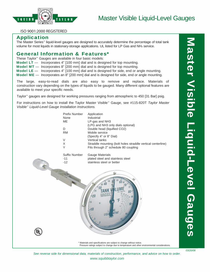
Application The Master Series™ liquid-level gauges are de signed to ac cu rate ly de ter mine the per cent age of total tank vol ume for most liq uids in sta tion ary-stor age ap pli ca tions. UL list ed for LP Gas and NH3 ser vice.
General In for ma tion & Features*These Taylor™ Gaug es are available in four basic models:Model LT — Incorporates 4” [100 mm] dial and is de signed for top mount ing.Model MT — Incorporates 8” [200 mm] dial and is de signed for top mount ing.Model LE — Incorporates 4” [100 mm] dial and is de signed for side, end or angle mount ing.Model ME — Incorporates an 8” [200 mm] dial and is de signed for side, end or angle mount ing.
The large, easy-to-read di als are also easy to remove and re place. Ma te ri als of con struc tion vary de pend ing on the types of liq uids to be gauged. Many dif fer ent op tion al fea tures are avail able to meet your spe cif ic needs.
Taylor™ gauges are designed for work ing pres sures rang ing from at mo spher ic to 450 [31 Bar] psig.
For in struc tions on how to in stall the Taylor Master Visible™ Gauge, see #115-820T Taylor Master Visible™ Liq uid-Lev el Gauge In stal la tion In struc tions.
R
Prefix Number ApplicationNone IndustrialME LP-gas and NH3 (LPG and NH3 only dials optional)D Double head (liquified CO2)RM Mobile service (Specify 4” or 8” Dial)V Vertical tanksX Straddle mounting (bolt holes straddle vertical centerline)Y Fits through 2” schedule 80 coupling
Suffix Number Gauge Materials-11 plated steel and stainless steel-12 stainless steel or better
03/20/08
ISO 9001:2000 REGISTERED
* Materials and specifications are subject to change with out notice. Pressure ratings sub ject to change due to tem per a ture and other en vi ron men tal considerations.
T A Y L O RS Q U I B BM
aster Visible Liquid-Lev el G
auges
10480 Shady Trail #106 • Dallas, TX 75220 • (214) 357-4591 • FAX (214) 357-5923Website www.squibbtaylor.com • E-mail [email protected]
Master Visible Liquid-Level GaugesMaster Visible Liquid-Level Gauges
When Or der ing, Spec i fy: 1. Liquid to be gauged and spe cif ic grav i ty.2. Inside diameter of tank, head style: ellipsoidal,
semi-ellipsoidal or hemispherical.3. Complete model number desired {example ME????(A
or B)-11}.4. If a dial other than standard is required, furnish drawing
and/or details.5. Furnish tank drawings whenever ordering gauges for
an gle-mounting or for installation in vertical tanks.6. Tank mounting flange, if required (see chart above).
A
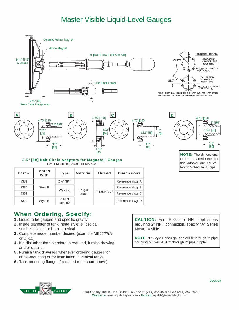
3.5” [89] Bolt Circle Adapters for Magnetel™ GaugesTaylor Machining Standard MS-508T
NOTE: The di men sions of the thread ed neck on this adapt er are equiv a-lent to Schedule 80 pipe.
CAUTION: For LP Gas or NH3 ap pli ca tions re quir ing 2” NPT con nec tion, spec i fy “A” Series Master Visible™
NOTE: “B” Style Series gauges will fit through 2” pipe coupling but will NOT fit through 2” pipe nipple.
B C D4.75” [120]
2.32”[59]
3.5”[89] 1.18”
[30]
2.32”[59]
4.75” [120]4.75” [120]
4.75” [120]
3” [76]
3.5”[89]
1.93” [49]
3.5”[89]
2.32” [59]
2” NPT2.5” NPT
Ceramic Pointer Magnet
Alnico Magnet
High and Low Float Arm Stop
140° Float Travel
9 9⁄16” [243]Diameter
2 9⁄16” [65]From Tank Flange max.
03/20/08
Part # MatesWith Type Material Thread Dimensions
5331
Style B
2 1⁄2” NPT
ForgedSteel
1⁄2”-13UNC-2B
Reference dwg. A
5330Welding
Reference dwg. B
5332 Reference dwg. C
5329 Style B 2” NPTsch. 80 Reference dwg. D
T A Y L O RS Q U I B B
See reverse side for dimensional data, materials of construction, performance, and advice on how to order.
Taylor RoadMaster Liquid-Level Gauges
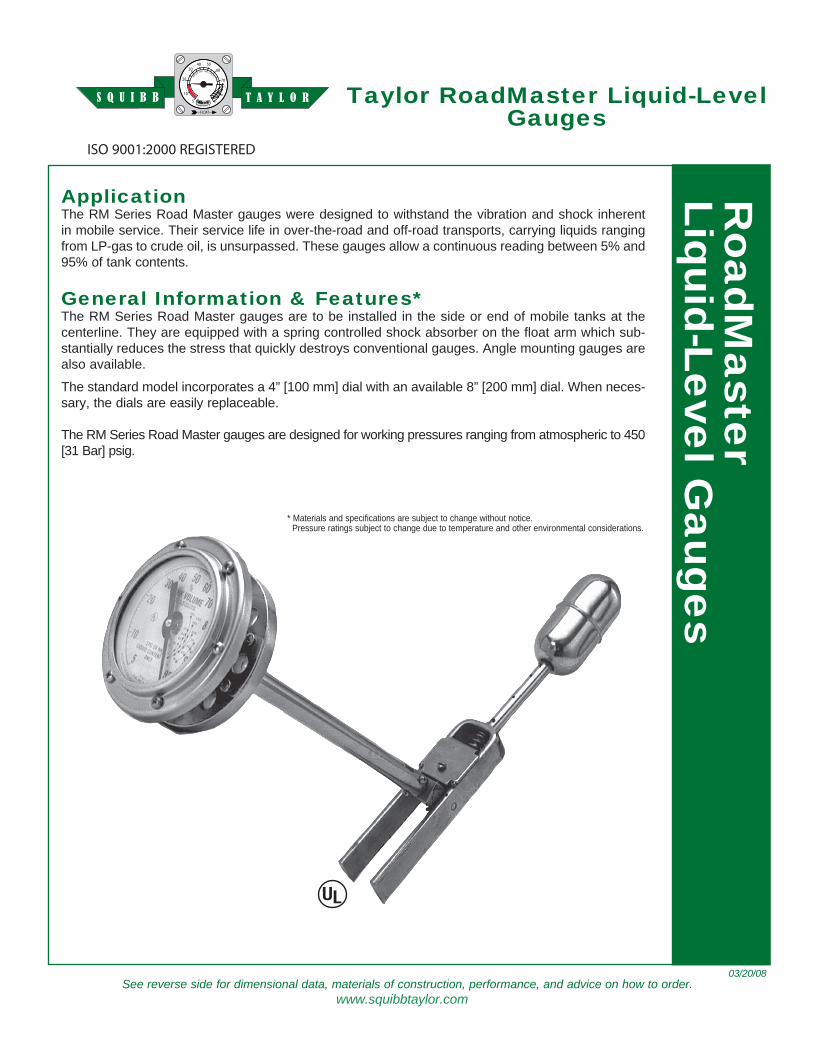
ApplicationThe RM Series Road Master gauges were de signed to with stand the vi bra tion and shock in her ent in mo bile service. Their ser vice life in over-the-road and off-road transports, car ry ing liquids rang ing from LP-gas to crude oil, is un sur passed. These gaug es al low a con tin u ous read ing be tween 5% and 95% of tank contents.
General In for ma tion & Fea tures*The RM Series Road Master gaug es are to be installed in the side or end of mobile tanks at the cen ter line. They are equipped with a spring controlled shock ab sorb er on the float arm which sub-stan tial ly reduces the stress that quick ly de stroys con ven tion al gauges. Angle mounting gaug es are also available.
The standard model in cor po rates a 4” [100 mm] dial with an available 8” [200 mm] dial. When nec es-sary, the dials are easily re place able.
The RM Series Road Master gauges are designed for work ing pres sures rang ing from at mo spher ic to 450 [31 Bar] psig.
* Materials and specifications are subject to change with out notice. Pressure ratings sub ject to change due to tem per a ture and other en vi ron men tal considerations.
03/20/08
ISO 9001:2000 REGISTERED
RoadM
aster
Liquid-Lev el Gauges
www.squibbtaylor.com
T A Y L O RS Q U I B B

10480 Shady Trail #106 • Dallas, TX 75220 • (214) 357-4591 • FAX (214) 357-5923Website www.squibbtaylor.com • E-mail [email protected]
Taylor RoadMaster Liquid-Level Gauges
When Or der ing, Specify:1. Liquid to be gauged and spe cif ic grav i ty.2. Inside diameter of tank heads, ellipsoidal,
semi-el lip soi dal or hemispherical.3. If a dial other than standard is required, furnish drawing
and/or details.4. Furnish tank drawings whenever ordering gauges for
angle-mounting or for installation in ver ti cal tanks.5. If tank mounting flange is required, order separately
from chart above.
A B C4.75” [120]
2.32”[59]
3.5”[89] 1.12”
[28]
3” [76]
3.5” [89] Bolt Circle Adapters for RoadMaster Gauges
2 1⁄2” NPT
140° Float travel
5 1⁄4” [133]Diameter
2 3⁄8” [143]From Tank Flange max.
Stainless steel float
Stainless steel head
Shock Absorber
4.75” [120]4.75” [120]
2.32”[59]
2.32”[59]
3.5”[89]
03/20/08
Part # MatesWith Type Material Thread Dimensions
5331
RM Series
2 1⁄2” NPTForgedSteel
1⁄2”-13UNC-2B
Reference dwg. A
5330 Welding Reference dwg. B
5334 3” NPT Reference dwg. C
T A Y L O RS Q U I B B
See reverse side for dimensional data, materials of construction, performance, and advice on how to order.
Magnetic Liquid-LevelGaug es For NH3 WithChem i cal Additives
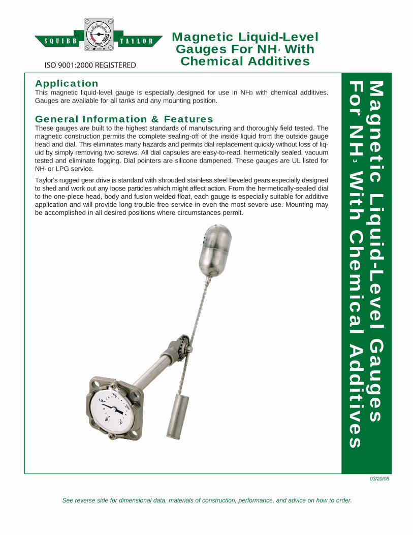
ApplicationThis magnetic liquid-level gauge is especially de signed for use in NH3 with chemical ad di tives. Gauges are available for all tanks and any mounting position.
General In for ma tion & FeaturesThese gauges are built to the highest standards of man u fac tur ing and thor ough ly field tested. The mag net ic con struc tion permits the com plete seal ing-off of the inside liquid from the outside gauge head and dial. This eliminates many hazards and permits dial re place ment quick ly with out loss of liq-uid by simply removing two screws. All dial cap sules are easy-to-read, her met i cal ly sealed, vac u um test ed and elim i nate fogging. Dial pointers are silicone dampened. These gauges are UL listed for NH3 or LPG ser vice.
Taylor‘s rugged gear drive is stan dard with shrouded stainless steel bev eled gears es pe cial ly de signed to shed and work out any loose par ti cles which might affect action. From the her met i cal ly-sealed dial to the one-piece head, body and fusion welded float, each gauge is es pe cial ly suit able for ad di tive ap pli ca tion and will pro vide long trou ble-free ser vice in even the most severe use. Mount ing may be ac com plished in all de sired po si tions where cir cum stanc es per mit.
03/20/08
ISO 9001:2000 REGISTERED Ma
gn
etic
Liq
uid
-Le
vel G
au
ge
sF
or N
H3 W
ith C
he
m i c
al A
d d
i tives
T A Y L O RS Q U I B B
10480 Shady Trail #106 • Dallas, TX 75220 • (214) 357-4591 • FAX (214) 357-5923Website www.squibbtaylor.com • E-mail [email protected]
* Specifications subject to change without notice. Ratings sub ject to change due to tem per a ture and other environmental considerations.
Magnetic Liquid-Level GaugesFor NH3 With Chemical Additives
Materials of ConstructionCounterbalance & Support TubeStainless steel.GasketNeoprene.Mounting ScrewsStainless steel.All Other ComponentsStainless steel, except for nickel plated alnico magnet.
General Specifications*Temperature RangeStandard range is -40°F to 158°F, -40C to 70CAccuracyDependent on proper sizing of gauge and tank con fig u ra-tion. When equipped with Junior dial, overall ac cu ra cy is ±5%, Senior dial is ±3%.Shock & VibrationSuitable for mobile service applicationsWorking Pressure450 psig [31 Bar]UL ListingUL listed for NH3 service
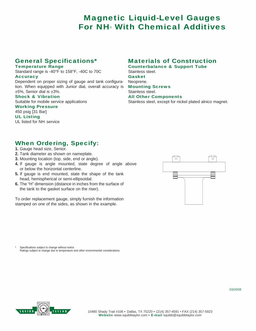
When Ordering, Specify:1. Gauge head size, Senior.2. Tank diameter as shown on nameplate. 3. Mounting location (top, side, end or angle).4. If gauge is angle mounted, state degree of angle above or below the horizontal centerline.5. If gauge is end mounted, state the shape of the tank
head, hemispherical or semi-ellipsoidal.6. The “H” dimension (distance in inches from the surface of
the tank to the gasket surface on the riser).
To order replacement gauge, simply furnish the in for ma tion stamped on one of the sides, as shown in the example.
03/20/08
T A Y L O RS Q U I B B
www.squibbtaylor.com
See reverse side for dimensional data, materials of construction, performance, and advice on how to order.
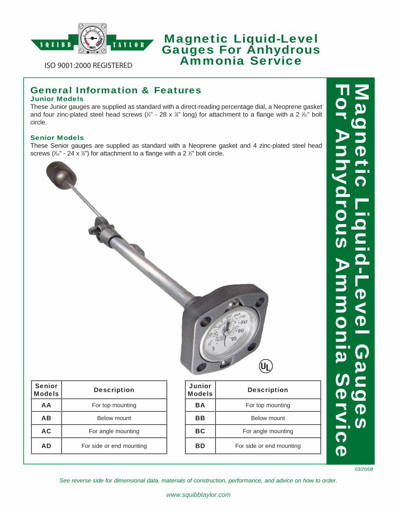
General In for ma tion & Fea turesJunior ModelsThese Jun ior gaug es are supplied as standard with a di rect-read ing percentage dial, a Neo prene gasket and four zinc-plated steel head screws (1⁄4” - 28 x 7⁄8” long) for at tach ment to a flange with a 2 1⁄32” bolt circle.
Senior ModelsThese Senior gauges are supplied as standard with a Neo prene gasket and 4 zinc-plated steel head screws (5⁄16” - 24 x 7⁄8”) for at tach ment to a flange with a 2 1⁄2” bolt cir cle.
Mag net ic Liquid-LevelGaug es For Anhydrous
Am mo nia Ser vice
03/20/08
ISO 9001:2000 REGISTERED
T A Y L O RS Q U I B BM
agnetic
Liq
uid
-Leve
l Gaug es
For A
n hy d
rous A
m m
o nia
Ser vic
e
JuniorModels Description
BA For top mounting
BB Below mount
BC For angle mounting
BD For side or end mounting
SeniorModels Description
AA For top mounting
AB Below mount
AC For angle mounting
AD For side or end mounting
10480 Shady Trail #106 • Dallas, TX 75220 • (214) 357-4591 • FAX (214) 357-5923Website www.squibbtaylor.com • E-mail [email protected]
* Materials and specifications are subject to change with out notice. Pressure ratings sub ject to change due to tem per a ture and other en vi ron men tal considerations.
Magnetic Liquid-Level GaugesFor Anhydrous Ammonia Ser vice
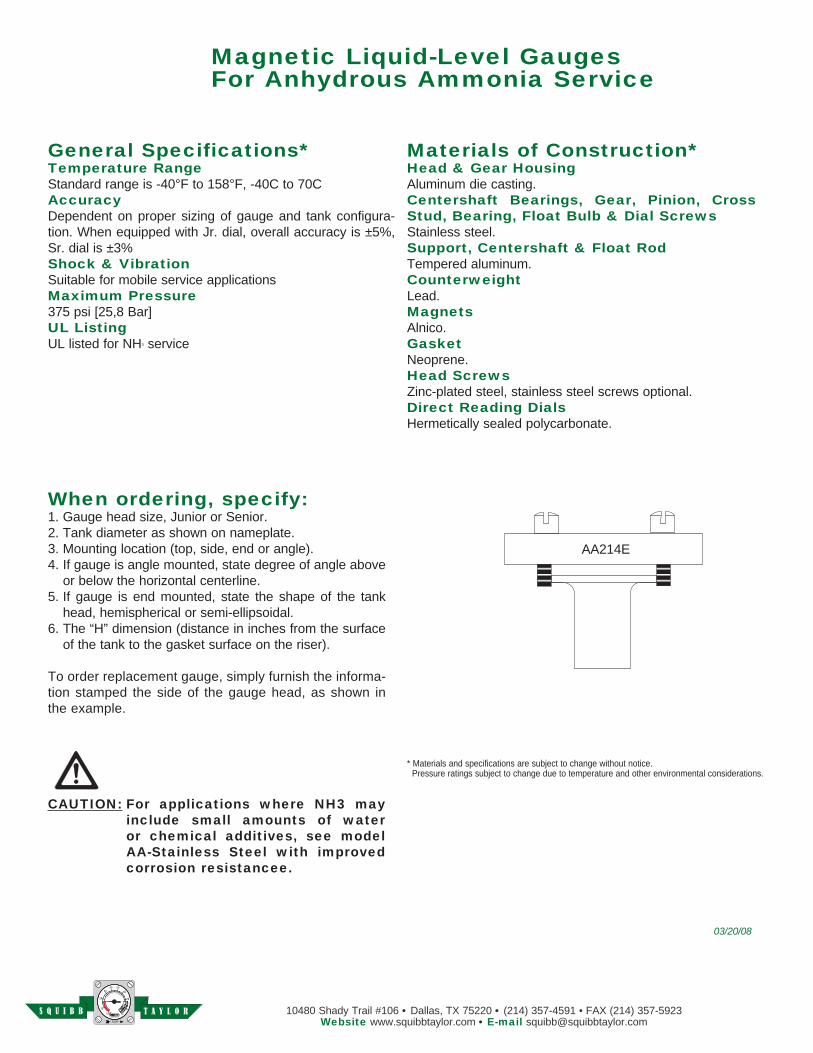
AA214E
Materials of Construction*Head & Gear HousingAluminum die casting.Centershaft Bearings, Gear, Pinion, Cross Stud, Bear ing, Float Bulb & Dial ScrewsStainless steel. Support, Centershaft & Float RodTempered alu mi num.CounterweightLead.MagnetsAlnico.GasketNeoprene.Head ScrewsZinc-plated steel, stainless steel screws optional.Direct Reading DialsHermetically sealed polycarbonate.
General Specifications*Temperature RangeStandard range is -40°F to 158°F, -40C to 70CAccuracyDependent on proper sizing of gauge and tank con fig u ra-tion. When equipped with Jr. dial, overall ac cu ra cy is ±5%, Sr. dial is ±3%Shock & VibrationSuitable for mobile service applicationsMaximum Pressure375 psi [25,8 Bar]UL ListingUL listed for NH3 service
When ordering, specify:1. Gauge head size, Junior or Senior.2. Tank diameter as shown on nameplate. 3. Mounting location (top, side, end or angle).4. If gauge is angle mounted, state degree of angle above
or below the horizontal centerline.5. If gauge is end mounted, state the shape of the tank
head, hemispherical or semi-ellipsoidal.6. The “H” dimension (distance in inches from the surface
of the tank to the gasket surface on the riser).
To order replacement gauge, simply furnish the in for ma-tion stamped the side of the gauge head, as shown in the example.
CAUTION: For applications where NH3 may include small amounts of water or chemical additives, see model AA-Stainless Steel with improved corrosion resistancee.
03/20/08
T A Y L O RS Q U I B B
www.squibbtaylor.com
See reverse side for dimensional data, materials of construction, performance, and advice on how to order.
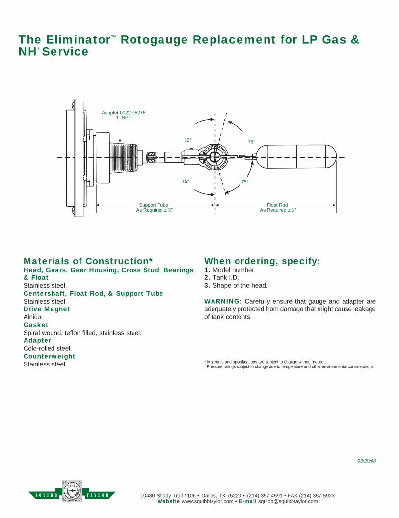
The Eliminator™ Rotogauge Replacement
For LP Gas & NH3 Service
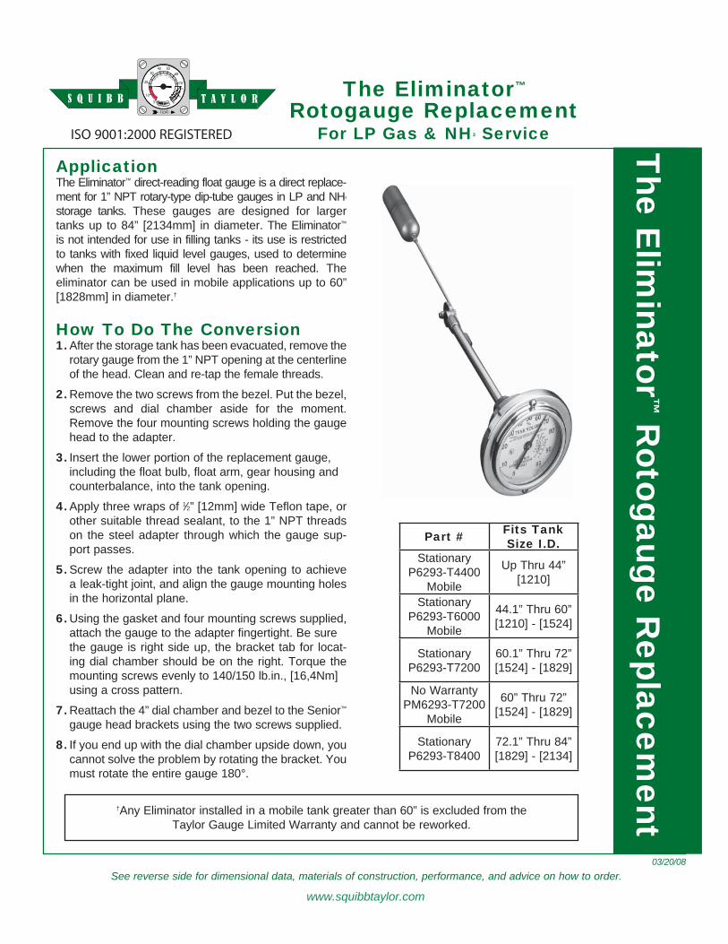
ApplicationThe Eliminator™ direct-reading float gauge is a direct re place-ment for 1” NPT rotary-type dip-tube gauges in LP and NH3 storage tanks. These gauges are de signed for larger tanks up to 84” [2134mm] in diameter. The Elim i na tor™ is not intended for use in filling tanks - its use is re strict ed to tanks with fixed liquid level gauges, used to determine when the maximum fill level has been reached. The eliminator can be used in mobile ap pli ca tions up to 60” [1828mm] in diameter.†
How To Do The Conversion1. After the storage tank has been evacuated, remove the
ro ta ry gauge from the 1” NPT open ing at the centerline of the head. Clean and re-tap the fe male threads.
2. Remove the two screws from the bezel. Put the bezel, screws and dial chamber aside for the moment. Remove the four mount ing screws holding the gauge head to the adapt er.
3. Insert the lower portion of the replacement gauge, including the float bulb, float arm, gear hous ing and counterbalance, into the tank open ing.
4. Apply three wraps of 1⁄2” [12mm] wide Te flon tape, or other suitable thread seal ant, to the 1” NPT threads on the steel adapt er through which the gauge sup-port pass es.
5. Screw the adapter into the tank open ing to achieve a leak-tight joint, and align the gauge mounting holes in the hor i zon tal plane.
6. Using the gasket and four mounting screws supplied, attach the gauge to the adapter fingertight. Be sure the gauge is right side up, the bracket tab for lo cat-ing dial cham ber should be on the right. Torque the mounting screws even ly to 140/150 lb.in., [16,4Nm]
us ing a cross pat tern.
7. Reattach the 4” dial chamber and be zel to the Se nior™ gauge head brackets using the two screws supplied.
8. If you end up with the dial cham ber up side down, you cannot solve the problem by ro tat ing the brack et. You must ro tate the en tire gauge 180°.
[METRIC]
03/20/08
ISO 9001:2000 REGISTERED
†Any Eliminator installed in a mobile tank greater than 60” is excluded from the Taylor Gauge Limited Warranty and cannot be reworked.
Part # Fits TankSize I.D.
StationaryP6293-T4400
Mobile
Up Thru 44”[1210]
StationaryP6293-T6000
Mobile
44.1” Thru 60”[1210] - [1524]
StationaryP6293-T7200
60.1” Thru 72”[1524] - [1829]
No WarrantyPM6293-T7200
Mobile
60” Thru 72”[1524] - [1829]
StationaryP6293-T8400
72.1” Thru 84”[1829] - [2134]
T A Y L O RS Q U I B BThe Elim
inator™ R
otogauge Re place m
ent
The Eliminator™ Rotogauge Replacement for LP Gas & NH3 Service
Materials of Construction*Head, Gears, Gear Housing, Cross Stud, Bearings & FloatStainless steel.Centershaft, Float Rod, & Support TubeStainless steel.Drive MagnetAlnico.GasketSpiral wound, teflon filled, stainless steel.AdapterCold-rolled steel.CounterweightStainless steel.
When or der ing, specify:1. Model number.2. Tank I.D.3. Shape of the head.
WARNING: Carefully ensure that gauge and adapter are ad e quate ly pro tect ed from dam age that might cause leak age of tank contents.
* Materials and specifications are subject to change with out notice. Pressure ratings sub ject to change due to tem per a ture and other en vi ron men tal considerations.
Adapter 0022-052761” NPT
75°
75°15°
15°
Support Tube As Required ± 1⁄8”
Float Rod As Required ± 1⁄8”
10480 Shady Trail #106 • Dallas, TX 75220 • (214) 357-4591 • FAX (214) 357-5923Website www.squibbtaylor.com • E-mail [email protected]
03/20/08
T A Y L O RS Q U I B B
See reverse side for dimensional data, materials of construction, performance, and advice on how to order.
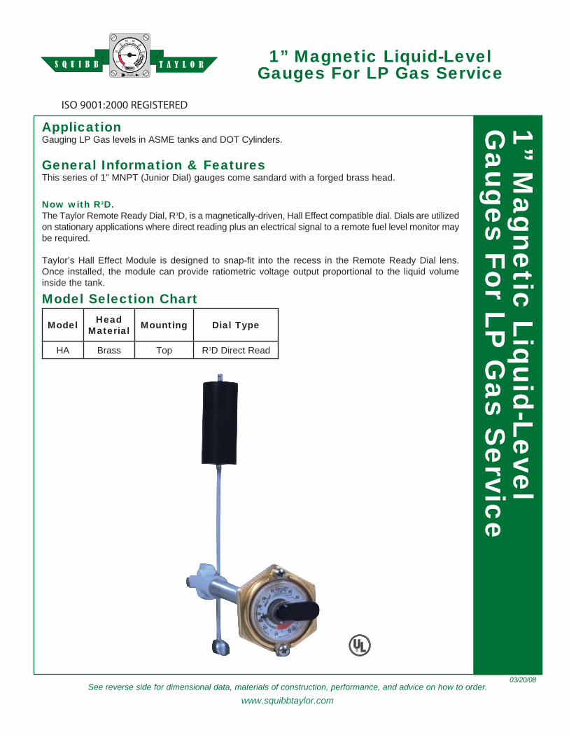
1” Magnetic Liquid-LevelGaug es For LP Gas Service
03/20/08
ISO 9001:2000 REGISTERED
ApplicationGauging LP Gas levels in ASME tanks and DOT Cyl in ders.
General In for ma tion & Fea turesThis series of 1” MNPT (Junior Dial) gauges come sandard with a forged brass head.
Now with R3D.The Taylor Remote Ready Dial, R3D, is a magnetically-driven, Hall Effect compatible dial. Dials are uti lized on stationary applications where direct read ing plus an elec tri cal signal to a re mote fuel level monitor may be re quired.
Taylor’s Hall Effect Module is designed to snap-fit into the recess in the Remote Ready Dial lens. Once installed, the module can provide ratiometric voltage output proportional to the liquid volume inside the tank.
R
Model Se lec tion Chart
Model HeadMaterial Mounting Dial Type
HA Brass Top R3D Direct Read
T A Y L O RS Q U I B B1” M
ag net ic Liquid-Lev elG
aug es For LP G
as Ser vice
www.squibbtaylor.com
10480 Shady Trail #106 • Dallas, TX 75220 • (214) 357-4591 • FAX (214) 357-5923Website www.squibbtaylor.com • E-mail [email protected]
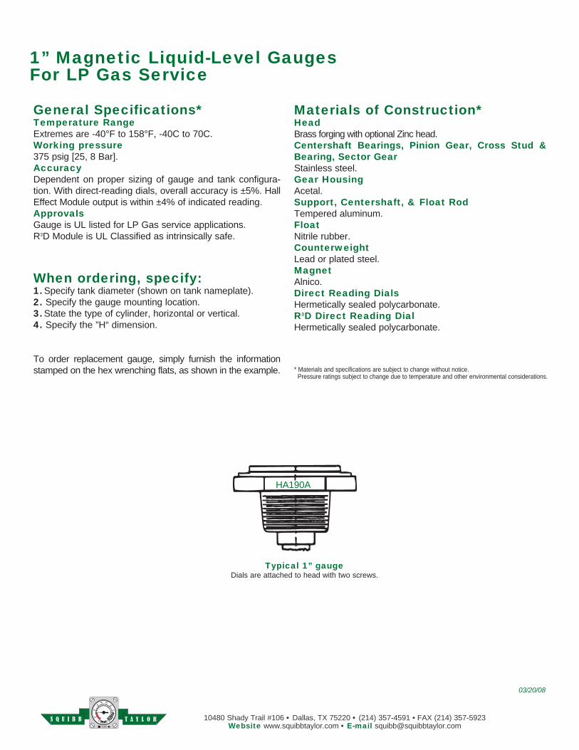
1” Magnetic Liquid-Lev el Gauges For LP Gas Service
Typical 1” gaugeDials are attached to head with two screws.
HA190A
03/20/08
Materials of Construction*HeadBrass forging with optional Zinc head.Centershaft Bearings, Pinion Gear, Cross Stud & Bear ing, Sector GearStain less steel. Gear HousingAcetal.Support, Centershaft, & Float Rod Tempered alu mi num.FloatNitrile rubber.Coun ter weight Lead or plated steel.MagnetAlnico.Direct Reading DialsHermetically sealed polycarbonate.R3D Direct Reading DialHermetically sealed polycarbonate.
* Materials and specifications are subject to change with out notice. Pressure ratings sub ject to change due to tem per a ture and other en vi ron men tal considerations.
General Specifications*Temperature Range Extremes are -40°F to 158°F, -40C to 70C.Working pressure 375 psig [25, 8 Bar].AccuracyDependent on proper sizing of gauge and tank con fig u ra-tion. With direct-reading dials, overall accuracy is ±5%. Hall Effect Module output is within ±4% of indicated reading.ApprovalsGauge is UL listed for LP Gas service ap pli ca tions.R3D Module is UL Classified as intrinsically safe.
When ordering, specify:1. Specify tank diameter (shown on tank name plate).2. Specify the gauge mounting location.3. State the type of cylinder, horizontal or vertical.4. Specify the ”H“ dimension.
To order replacement gauge, simply furnish the in for ma tion stamped on the hex wrenching flats, as shown in the ex am ple.
T A Y L O RS Q U I B B
See reverse side for dimensional data, materials of construction, performance, and advice on how to order.
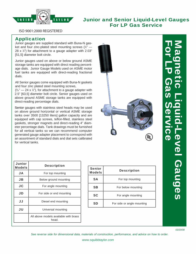
Junior and Senior Liquid-Level GaugesFor LP Gas Service
Application Junior gauges are supplied standard with Buna-N gas-ket and four zinc-plated steel mounting screws (1⁄4” — 28 x 7⁄8”) for attachment to a gauge adapter with 2.03” [51, 5] diameter bolt circle.
Junior gauges used on above or below ground ASME storage tanks are equipped with direct reading per cent-age dials. Junior Gauge Mod els used on ASME motor fuel tanks are equipped with direct-read ing frac tion al dials.
All Senior gauges come equipped with Buna-N gas kets and four zinc plated steel mount ing screws, (5⁄16” — 24 x 7⁄8”), for at tach ment to a gauge adapter with 2.5” [63, 5] diameter bolt circle. Senior gauges used on above ground ASME storage tanks are equipped with direct-reading per cent age di als.
Senior gauges with stainless steel heads may be used on above ground hor i zon tal or ver ti cal ASME stor age tanks over 3500 [13250 liters] gallon capacity and are equipped with cap screws, teflon-filled, stainless steel gas kets, stronger magnets and direct-reading 4” diam-eter per cent age dials. Tank draw ings must be fur nished for all ver ti cal tanks so we can recommend com put er gen er at ed gauge adapter place ment to cor re spond with an as sort ment of standard dials and dial sets calibrated for vertical tanks.
03/20/08
ISO 9001:2000 REGISTERED
�
JuniorModels Description
JA For top mounting
JB Below ground mounting
JC For angle mounting
JD For side or end mounting
JJ Diesel end mounting
JU Universal mounting
All above models available with brass head.
SeniorModels Description
SA For top mounting
SB For below mounting
SC For angle mounting
SD For side or angle mounting
T A Y L O RS Q U I B BM
agnetic Liquid-Level Gauges
For LP G
as Service
www.squibbtaylor.com
10480 Shady Trail #106 • Dallas, TX 75220 • (214) 357-4591 • FAX (214) 357-5923Website www.squibbtaylor.com • E-mail [email protected]
* Materials and specifications are subject to change with out notice. Pressure ratings sub ject to change due to tem per a ture and other en vi ron men tal considerations.
Junior Liquid-Level Gauges For LP Gas Ser vice
JA154I
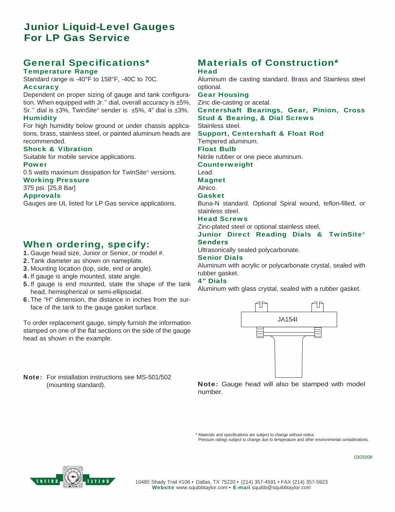
Materials of Construction*HeadAluminum die casting stan dard. Brass and Stainless steel optional.Gear HousingZinc die-casting or acetal. Centershaft Bearings, Gear, Pinion, Cross Stud & Bear ing, & Dial ScrewsStainless steel. Support, Centershaft & Float RodTempered alu mi num.Float BulbNitrile rubber or one piece alu mi num.CounterweightLead.MagnetAlnico.GasketBuna-N standard. Optional Spiral wound, teflon-filled, or stainless steel.Head ScrewsZinc-plated steel or optional stainless steel.Junior Direct Reading Dials & TwinSite®
SendersUltrasonically sealed polycarbonate.Senior DialsAluminum with acrylic or polycarbonate crystal, sealed with rubber gasket.4” DialsAluminum with glass crystal, sealed with a rub ber gasket.
General Specifications*Temperature RangeStandard range is -40°F to 158°F, -40C to 70C.AccuracyDependent on proper sizing of gauge and tank con fig u ra-tion. When equipped with Jr.™ dial, overall ac cu ra cy is ±5%, Sr.™ dial is ±3%, TwinSite® sender is ±5%, 4” dial is ±3%.HumidityFor high humidity below ground or under chassis ap pli ca-tions, brass, stainless steel, or painted alu mi num heads are recommended.Shock & VibrationSuitable for mobile service applications.Power0.5 watts maximum dissipation for TwinSite® versions.Working Pressure 375 psi. [25,8 Bar]ApprovalsGauges are UL listed for LP Gas service applications.
When ordering, specify:1. Gauge head size, Junior or Senior, or model #. 2. Tank diameter as shown on nameplate. 3. Mounting location (top, side, end or angle).4. If gauge is angle mounted, state angle.5. If gauge is end mounted, state the shape of the tank
head, hemispherical or semi-ellipsoidal.6. The “H” dimension, the distance in inches from the sur-
face of the tank to the gauge gasket surface.
To order replacement gauge, simply furnish the in for ma tion stamped on one of the flat sections on the side of the gauge head as shown in the example.
Note: For installation instructions see MS-501/502 (mounting standard). Note: Gauge head will also be stamped with model
number.
03/20/08
T A Y L O RS Q U I B B
See reverse side for dimensional data, materials of construction, performance, and advice on how to order.
The “One” Gauge™
Adjustable Liquid-Level Gauge
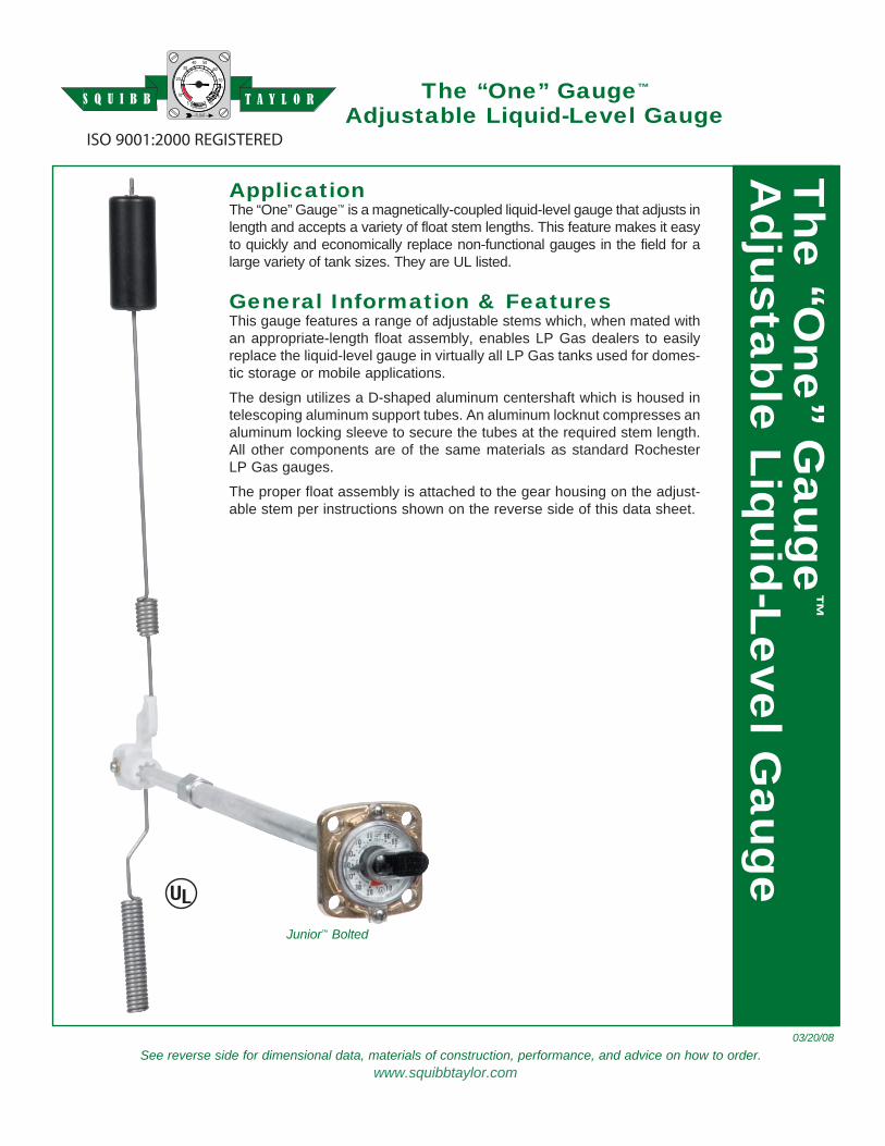
ApplicationThe “One” Gauge™ is a magnetically-cou pled liq uid-lev el gauge that ad justs in length and ac cepts a va ri ety of float stem lengths. This feature makes it easy to quickly and economically replace non-func tion al gaug es in the field for a large variety of tank siz es. They are UL listed.
General In for ma tion & Fea turesThis gauge features a range of ad just able stems which, when mated with an ap pro pri ate-length float as sem bly, enables LP Gas dealers to easily re place the liq uid-lev el gauge in vir tu al ly all LP Gas tanks used for do mes-tic storage or mobile applications.
The design utilizes a D-shaped alu mi num centershaft which is housed in telescoping alu mi num sup port tubes. An alu mi num lock nut com press es an aluminum locking sleeve to se cure the tubes at the required stem length. All oth er com po nents are of the same materials as stan dard Rochester LP Gas gauges.
The proper float assembly is at tached to the gear hous ing on the ad just-able stem per in struc tions shown on the re verse side of this data sheet.
03/20/08
ISO 9001:2000 REGISTERED
Junior™ Bolted
The “O
ne” Gauge
™
Ad just able Liquid-Lev el G
auge
www.squibbtaylor.com
T A Y L O RS Q U I B B
10480 Shady Trail #106 • Dallas, TX 75220 • (214) 357-4591 • FAX (214) 357-5923Website www.squibbtaylor.com • E-mail [email protected]
NOTE: Materials and specifications are subject to change with out notice. Pressure ratings sub ject to change due to tem per a ture and other en vi ron men tal considerations.
The “One” Gauge™
Adjustable Liquid-Level Gauge
03/20/08
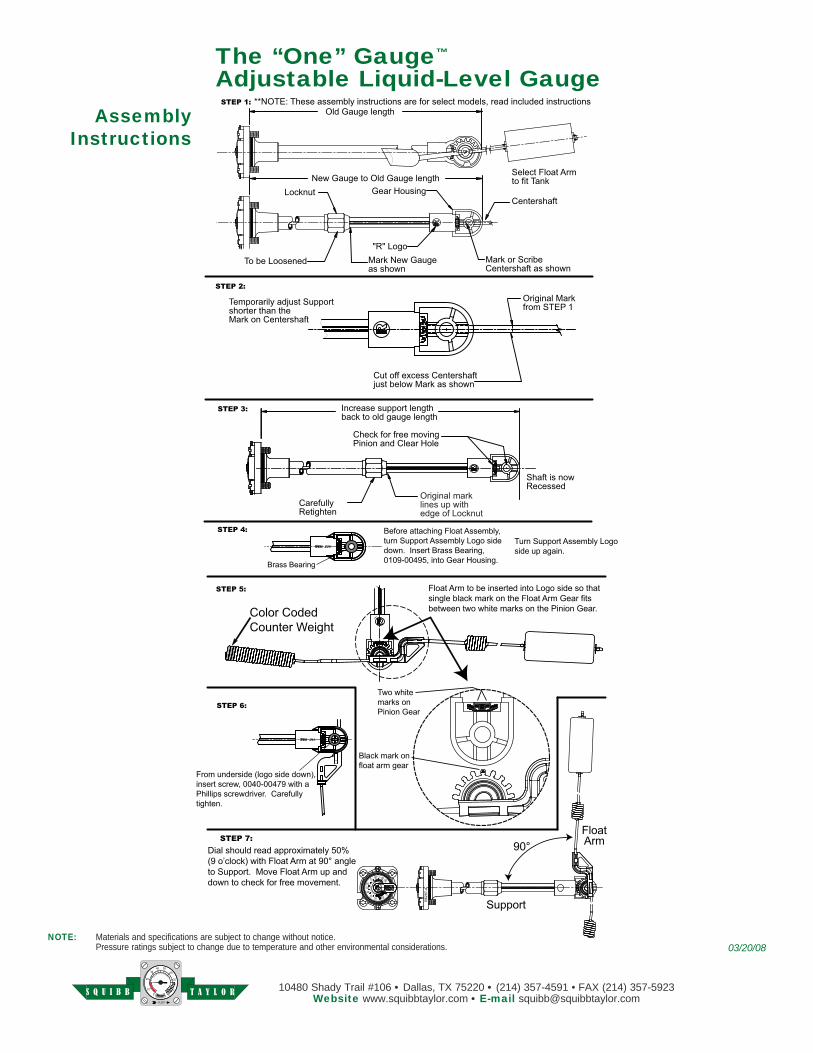
AssemblyInstructions
Old Gauge length
Mark or ScribeCentershaft as shown
STEP 1:
STEP 2:
Original Markfrom STEP 1
Cut off excess Centershaftjust below Mark as shown
Locknut Gear HousingCentershaft
STEP 3:
"R" LogoTo be Loosened
CarefullyRetighten
Check for free movingPinion and Clear Hole
STEP 4:
STEP 5:
STEP 6:
STEP 7:
Select Float Armto fit Tank
Shaft is nowRecessed
Increase support lengthback to old gauge length
Temporarily adjust Supportshorter than theMark on Centershaft
**NOTE: These assembly instructions are for select models, read included instructions
New Gauge to Old Gauge length
Mark New Gaugeas shown
Original marklines up withedge of Locknut
T A Y L O RS Q U I B B
10480 SHADY TRAIL LN. SUITE 106 P.O. BOX 541175DALLAS, TEXAS 75220 DALLAS, TEXAS 75354-1175PHONE (214) 357-4591 FAX (214) 357-5923
WEBSITE: www.squibbtaylor.com
MASTER Gauge AdapterMachining Standard
Note: Materials and specifications are subject to change with out notice. Pressure ratings sub ject to change due to tem per a ture and other en vi ron men tal considerations.
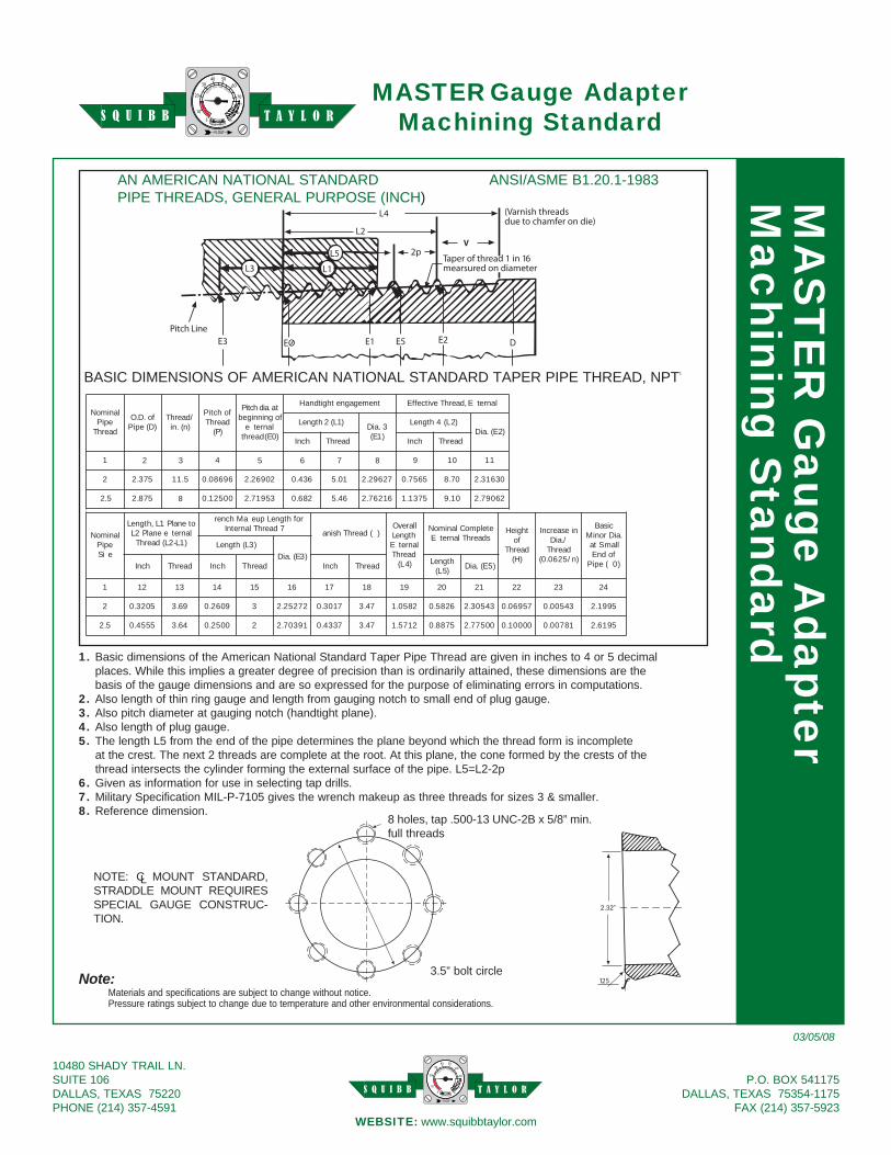
AN AMERICAN NATIONAL STANDARD ANSI/ASME B1.20.1-1983PIPE THREADS, GENERAL PURPOSE (INCH)
lanimoNepiPdaerhT
fo.D.O)D(epiP
/daerhT)n(.ni
fohctiPdaerhT
)P(
ta.aidhctiPbeginning of
e�ternal)0E(thread
tnemegagneHandtight E�ternal,daerhTevitceffE
)1L(2htgneL 3.aiD)1E(
)2L(4htgneL)2E(.aiD
Inch daerhT chnI daerhT
1 4 9 01 11
2 753.2 .511 69680.0 02962.2 364.0 01.5 27692.2 6557.0 70.8 30613.2
2.5 758.2 00521.0 53917.2 826.0 46.5 16267.2 7531.1 01.9 62097.2
32 5 6 87
8
lanimoNepiPe�iS
otenalP1L,htgneLlanret�eenalP2L
)1L-2L(daerhT
rofhtgneLpue�aMhcner�7daerhTlanretnI )�(daerhThsina�
llarevOhtgneL
lanret�EdaerhT
)4L(
etelpmoClanimoNsdaerhTlanret�E
thgieHfo
daerhT)H(
niesaercnI/.aiDdaerhT
)n/5260.0(
cisaB.aiDroniM
llamStafodnE
)0�(epiP
)3L(htgneL)3E(.aiD
hcnI daerhT hcnI daerTh Inch aderhT htgneL)5L( )5E(.aiD
1 21 31 41 51 61 71 81 91 02 12 22 32 42
2 5023.0 96.3 9062.0 3 27252.2 7103.0 74.3 2850.1 6285.0 34503.2 75960.0 34500.0 5991.2
5.2 5554.0 46.3 0052.0 2 19307.2 7334.0 74.3 2175.1 5788.0 00577.2 00001.0 18700.0 5916.2
BASIC DIMENSIONS OF AMERICAN NATIONAL STANDARD TAPER PIPE THREAD, NPT1
8 holes, tap .500-13 UNC-2B x 5/8” min. full threads
3.5” bolt circle
NOTE: C MOUNT STANDARD, STRAD DLE MOUNT REQUIRES SPE CIAL GAUGE CON STRUC-TION.
L
1. Basic dimensions of the American National Standard Taper Pipe Thread are given in inches to 4 or 5 decimal places. While this implies a greater degree of precision than is ordinarily attained, these di men sions are the basis of the gauge dimensions and are so expressed for the purpose of eliminating errors in com pu ta tions.
2. Also length of thin ring gauge and length from gauging notch to small end of plug gauge.3. Also pitch diameter at gauging notch (handtight plane).4. Also length of plug gauge.5. The length L5 from the end of the pipe determines the plane beyond which the thread form is incomplete
at the crest. The next 2 threads are complete at the root. At this plane, the cone formed by the crests of the thread intersects the cyl in der forming the external surface of the pipe. L5=L2-2p
6. Given as information for use in selecting tap drills.7. Military Specification MIL-P-7105 gives the wrench makeup as three threads for sizes 3 & smaller.8. Reference dimension.
03/05/08
MA
ST
ER
Gauge A
dapter M
achining Standard
T A Y L O RS Q U I B B
T A Y L O RS Q U I B B
10480 Shady Trail #106 • Dallas, TX 75220 • (214) 357-4591 • FAX (214) 357-5923Website www.squibbtaylor.com • E-mail [email protected]
T A Y L O RS Q U I B B
03/20/08


![Digital Gauge General Catalog - magnescale.com · Digital Gauge General Catalog ... [Shape] No symbol : straight L : right angle V : pneumatic push ... 60mm Stroke 25mm Stroke 30mm](https://img.pdfslide.us/doc/110x75/5ad9ce1e7f8b9a6d7e8bd65c/digital-gauge-general-catalog-gauge-general-catalog-shape-no-symbol-straight.jpg)