Embed Size (px)
Citation preview
Self-study programme 321
Service Training
The Golf 2004Running gear
Design and function
2
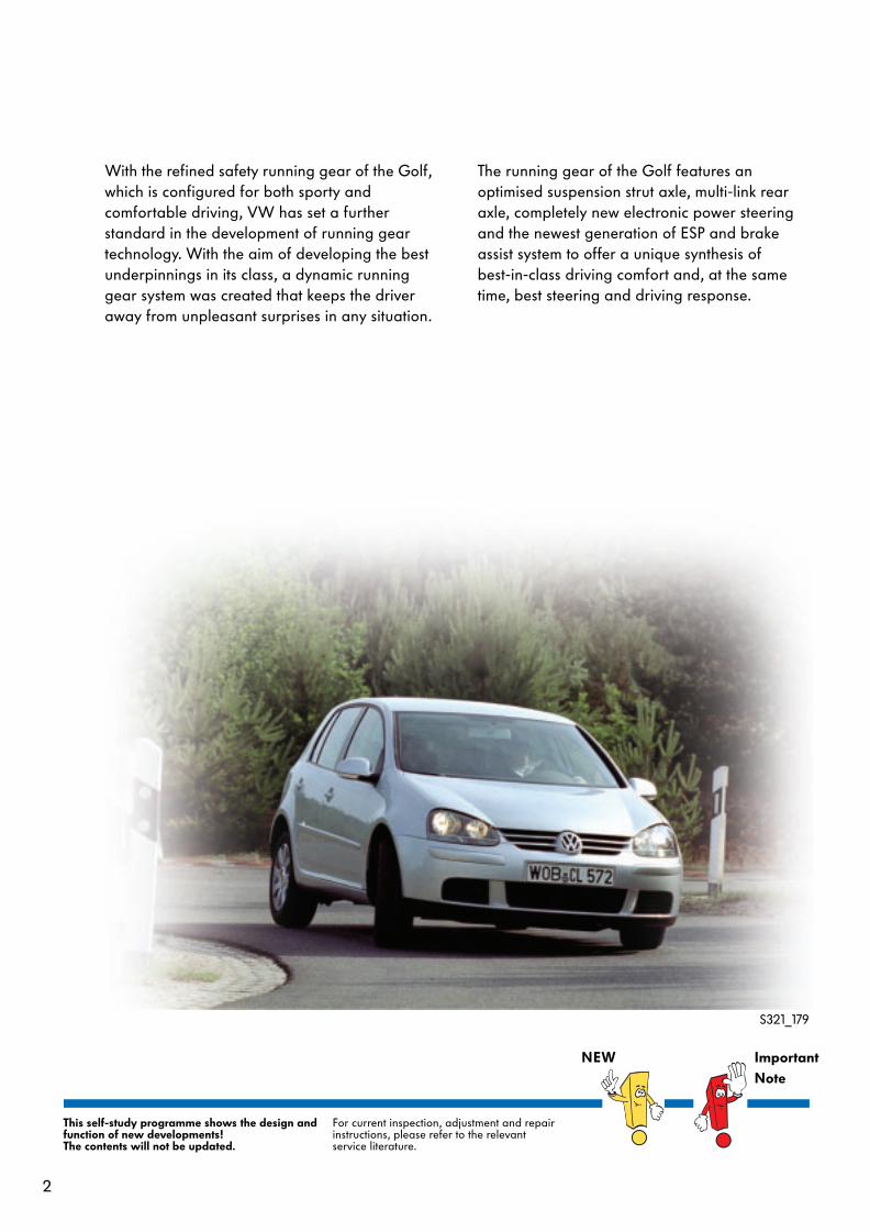
With the refined safety running gear of the Golf, which is configured for both sporty and comfortable driving, VW has set a further standard in the development of running gear technology. With the aim of developing the best underpinnings in its class, a dynamic running gear system was created that keeps the driver away from unpleasant surprises in any situation.
The running gear of the Golf features an optimised suspension strut axle, multi-link rear axle, completely new electronic power steering and the newest generation of ESP and brake assist system to offer a unique synthesis of best-in-class driving comfort and, at the same time, best steering and driving response.
This self-study programme shows the design and function of new developments!The contents will not be updated.
For current inspection, adjustment and repair instructions, please refer to the relevant service literature.
NEW ImportantNote
S321_179
3
Contents
Introduction . . . . . . . . . . . . . . . . . . . . . . . . . . . . . . . . . . .4
Front axle . . . . . . . . . . . . . . . . . . . . . . . . . . . . . . . . . . . . 6
Rear axle . . . . . . . . . . . . . . . . . . . . . . . . . . . . . . . . . . . 12
Steering . . . . . . . . . . . . . . . . . . . . . . . . . . . . . . . . . . . . 17
Brake system . . . . . . . . . . . . . . . . . . . . . . . . . . . . . . . . .24
Wheels and tyres. . . . . . . . . . . . . . . . . . . . . . . . . . . . . .35
Foot pedal cluster . . . . . . . . . . . . . . . . . . . . . . . . . . . . .36
Service . . . . . . . . . . . . . . . . . . . . . . . . . . . . . . . . . . . . . . 41
Test yourself . . . . . . . . . . . . . . . . . . . . . . . . . . . . . . . . . 43
4
Introduction
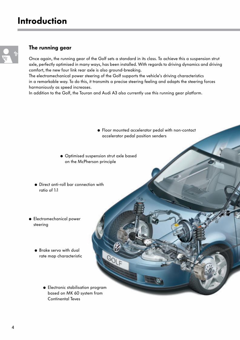
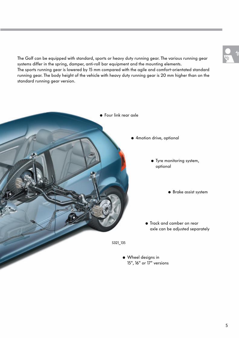
● Brake servo with dual rate map characteristic
The running gear
Once again, the running gear of the Golf sets a standard in its class. To achieve this a suspension strut axle, perfectly optimised in many ways, has been installed. With regards to driving dynamics and driving comfort, the new four link rear axle is also ground-breaking. The electromechanical power steering of the Golf supports the vehicle's driving characteristics in a remarkable way. To do this, it transmits a precise steering feeling and adapts the steering forces harmoniously as speed increases. In addition to the Golf, the Touran and Audi A3 also currently use this running gear platform.
● Electronic stabilisation program based on MK 60 system from Continental Teves
● Electromechanical power steering
● Direct anti-roll bar connection with ratio of 1:1
● Optimised suspension strut axle basedon the McPherson principle
● Floor mounted accelerator pedal with non-contactaccelerator pedal position senders
5
S321_135
● Four link rear axle
● 4motion drive, optional
● Tyre monitoring system,optional
● Brake assist system
● Track and camber on rear axle can be adjusted separately
The Golf can be equipped with standard, sports or heavy duty running gear. The various running gear systems differ in the spring, damper, anti-roll bar equipment and the mounting elements.The sports running gear is lowered by 15 mm compared with the agile and comfort-orientated standard running gear. The body height of the vehicle with heavy duty running gear is 20 mm higher than on the standard running gear version.
● Wheel designs in 15", 16" or 17" versions
6
Front axle
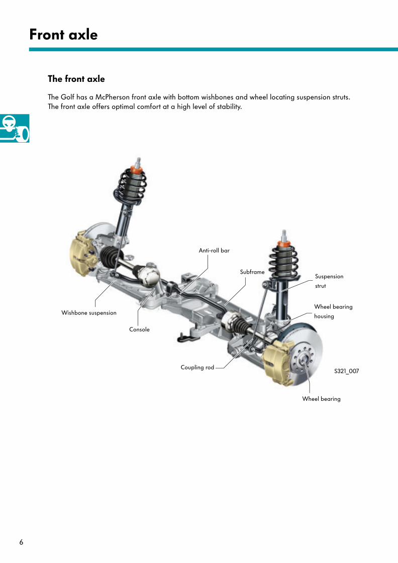
The front axle
The Golf has a McPherson front axle with bottom wishbones and wheel locating suspension struts. The front axle offers optimal comfort at a high level of stability.
Suspension
strut
Anti-roll bar
Wishbone suspension
Subframe
Coupling rod
Wheel bearing
housing
Wheel bearing
Console
S321_007

7
Subframe
Subframe
Console
Console
The subframe comprises of three parts and is made of aluminium. It is joined to the body at six points. With this type of connection, the body is stiffened in the front area. The optimal layout of the bonded rubber bushes in the wishbones and suspension strut mountings has a positive influence on the driving dynamics and body acoustics.
S321_022
Key:
= Bonding point to body
The wheel bearings are of the 3rd generation. This type of component is a compact wheel bearing unit comprised of wheel hub and wheel bearing, which is bolted from the interior to the swivel mounting by four bolts.
The advantage of this wheel bearing is that the bearing play no longer has to be adjusted.
S321_020
Wheel bearing
8
Front axle
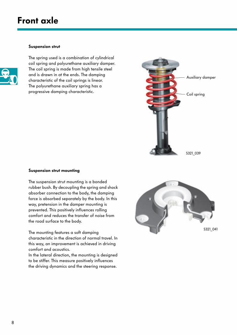
The suspension strut mounting is a bonded rubber bush. By decoupling the spring and shock absorber connection to the body, the damping force is absorbed separately by the body. In this way, pretension in the damper mounting is prevented. This positively influences rolling comfort and reduces the transfer of noise from the road surface to the body.
The mounting features a soft damping characteristic in the direction of normal travel. In this way, an improvement is achieved in driving comfort and acoustics. In the lateral direction, the mounting is designed to be stiffer. This measure positively influences the driving dynamics and the steering response.
S321_039
Suspension strut mounting
Suspension strut
The spring used is a combination of cylindrical coil spring and polyurethane auxiliary damper. The coil spring is made from high tensile steel and is drawn in at the ends. The damping characteristic of the coil springs is linear. The polyurethane auxiliary spring has a progressive damping characteristic.
Auxiliary damper
Coil spring
S321_041
9
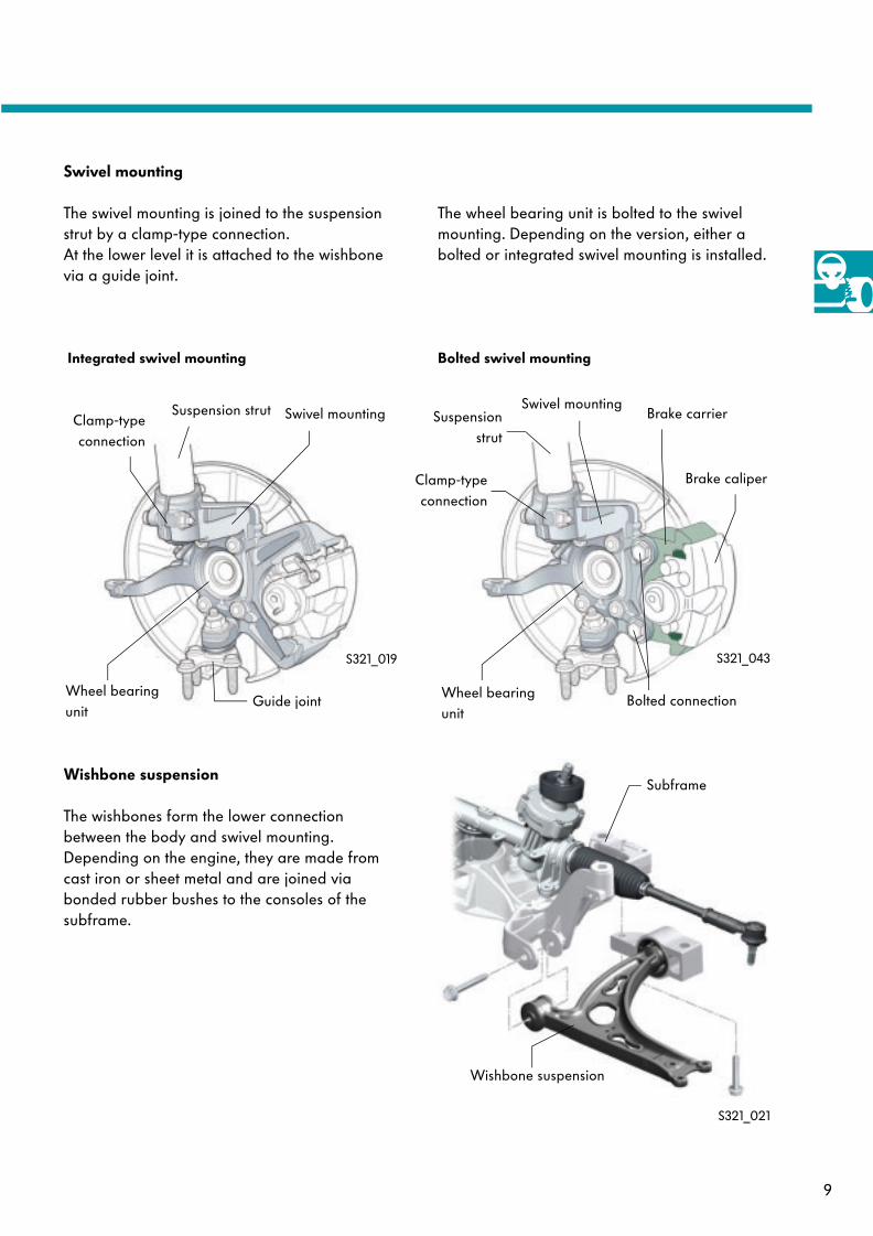
Swivel mounting
The swivel mounting is joined to the suspension strut by a clamp-type connection. At the lower level it is attached to the wishbone via a guide joint.
Suspension strut Swivel mountingClamp-typeconnection
Guide jointWheel bearing unit
Wishbone suspension
The wishbones form the lower connection between the body and swivel mounting. Depending on the engine, they are made from cast iron or sheet metal and are joined via bonded rubber bushes to the consoles of the subframe.
Wishbone suspension
Subframe
S321_021
S321_019 S321_043
The wheel bearing unit is bolted to the swivel mounting. Depending on the version, either a bolted or integrated swivel mounting is installed.
Integrated swivel mounting Bolted swivel mounting
Suspensionstrut
Swivel mounting
Clamp-typeconnection
Bolted connectionWheel bearing unit
Brake carrier
Brake caliper
10
Front axle
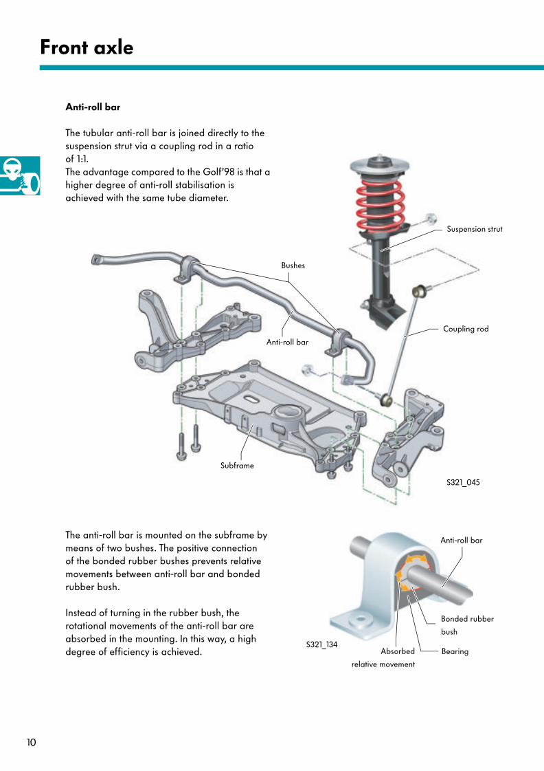
Anti-roll bar
The tubular anti-roll bar is joined directly to the suspension strut via a coupling rod in a ratio of 1:1. The advantage compared to the Golf’98 is that a higher degree of anti-roll stabilisation is achieved with the same tube diameter.
Anti-roll bar
Coupling rod
Suspension strut
Bushes
The anti-roll bar is mounted on the subframe by means of two bushes. The positive connection of the bonded rubber bushes prevents relative movements between anti-roll bar and bonded rubber bush.
Instead of turning in the rubber bush, the rotational movements of the anti-roll bar are absorbed in the mounting. In this way, a high degree of efficiency is achieved.
Subframe
S321_045
Anti-roll bar
Bonded rubber
bush
Absorbed
relative movement
BearingS321_134
11
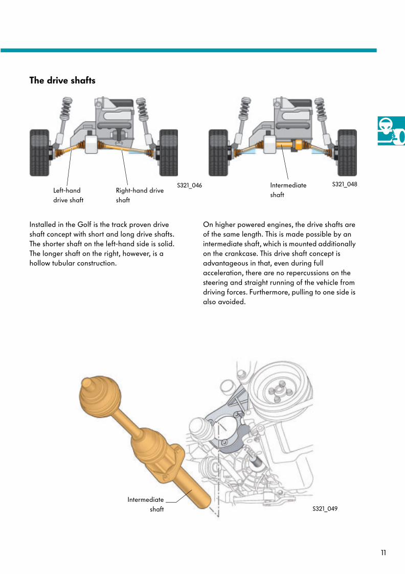
The drive shafts
Installed in the Golf is the track proven drive shaft concept with short and long drive shafts. The shorter shaft on the left-hand side is solid. The longer shaft on the right, however, is a hollow tubular construction.
S321_046Left-hand drive shaft
Right-hand drive shaft
On higher powered engines, the drive shafts are of the same length. This is made possible by an intermediate shaft, which is mounted additionally on the crankcase. This drive shaft concept is advantageous in that, even during full acceleration, there are no repercussions on the steering and straight running of the vehicle from driving forces. Furthermore, pulling to one side is also avoided.
Intermediate shaft
Intermediateshaft
S321_048
S321_049
12
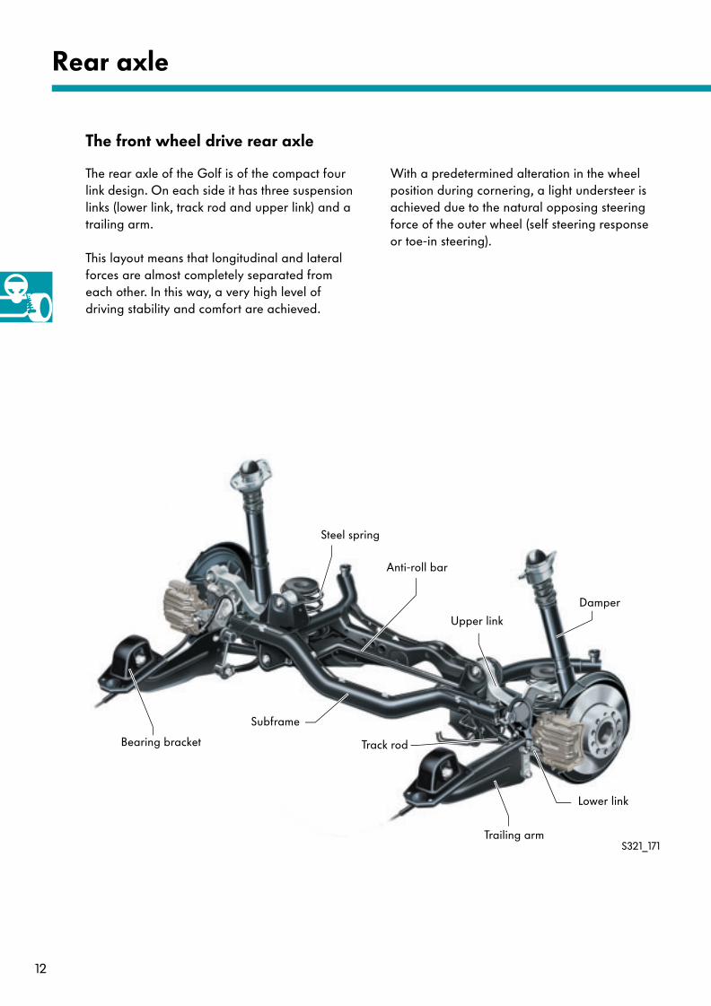
The front wheel drive rear axle
The rear axle of the Golf is of the compact four link design. On each side it has three suspension links (lower link, track rod and upper link) and a trailing arm.
This layout means that longitudinal and lateral forces are almost completely separated from each other. In this way, a very high level of driving stability and comfort are achieved.
Rear axle
Steel spring
Bearing bracket
Anti-roll bar
Subframe
Track rod
Lower link
Trailing arm
Damper
Upper link
With a predetermined alteration in the wheel position during cornering, a light understeer is achieved due to the natural opposing steering force of the outer wheel (self steering response or toe-in steering).
S321_171
13
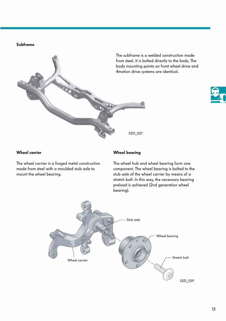
Subframe
Wheel carrier
The subframe is a welded construction made from steel. It is bolted directly to the body. The body mounting points on front wheel drive and 4motion drive systems are identical.
The wheel carrier is a forged metal construction made from steel with a moulded stub axle to mount the wheel bearing.
Wheel bearing
The wheel hub and wheel bearing form one component. The wheel bearing is bolted to the stub axle of the wheel carrier by means of a stretch bolt. In this way, the necessary bearing preload is achieved (2nd generation wheel bearing).
S321_027
S321_029
Stub axle
Wheel bearing
Stretch boltWheel carrier
14
Rear axle
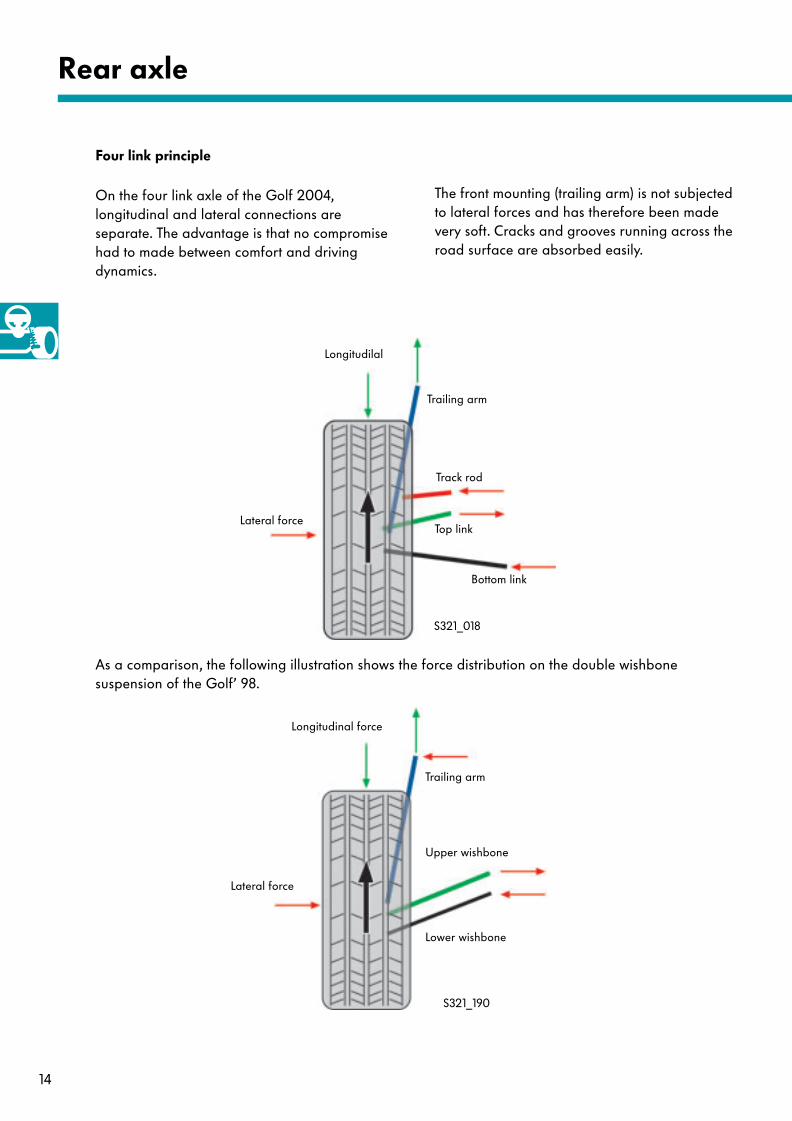
Four link principle
Longitudilal
Lateral force
Trailing arm
Track rod
Top link
Bottom link
S321_018
On the four link axle of the Golf 2004, longitudinal and lateral connections are separate. The advantage is that no compromise had to made between comfort and driving dynamics.
As a comparison, the following illustration shows the force distribution on the double wishbone suspension of the Golf’ 98.
S321_190
Longitudinal force
Trailing arm
Upper wishbone
Lower wishbone
Lateral force
The front mounting (trailing arm) is not subjected to lateral forces and has therefore been made very soft. Cracks and grooves running across the road surface are absorbed easily.
15
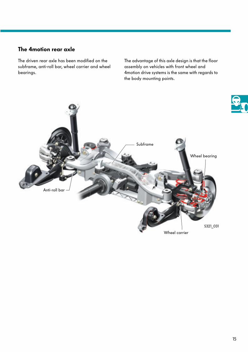
The 4motion rear axle
The driven rear axle has been modified on the subframe, anti-roll bar, wheel carrier and wheel bearings.
Anti-roll bar
Subframe
Wheel bearing
Wheel carrier
S321_031
The advantage of this axle design is that the floor assembly on vehicles with front wheel and 4motion drive systems is the same with regards to the body mounting points.
16
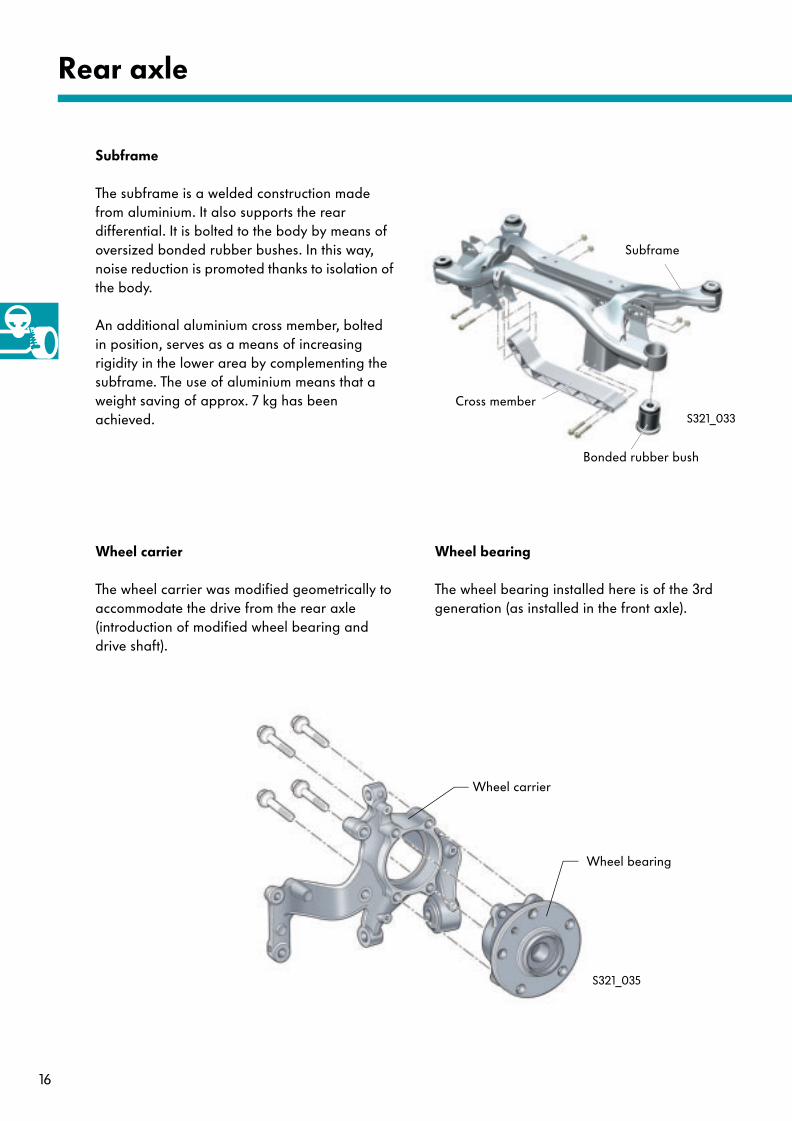
Subframe
Bonded rubber bush
Cross member
Rear axle
Subframe
Wheel bearingWheel carrier
The subframe is a welded construction made from aluminium. It also supports the rear differential. It is bolted to the body by means of oversized bonded rubber bushes. In this way, noise reduction is promoted thanks to isolation of the body.
An additional aluminium cross member, boltedin position, serves as a means of increasing rigidity in the lower area by complementing the subframe. The use of aluminium means that a weight saving of approx. 7 kg has been achieved.
The wheel carrier was modified geometrically to accommodate the drive from the rear axle (introduction of modified wheel bearing and drive shaft).
The wheel bearing installed here is of the 3rd generation (as installed in the front axle).
S321_033
S321_035
Wheel carrier
Wheel bearing
17
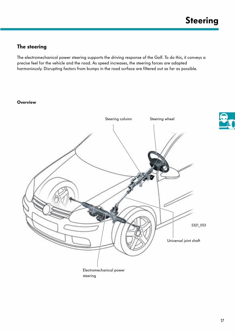
The steering
Overview
Steering wheelSteering column
Electromechanical power steering
Universal joint shaft
Steering
S321_053
The electromechanical power steering supports the driving response of the Golf. To do this, it conveys a precise feel for the vehicle and the road. As speed increases, the steering forces are adapted harmoniously. Disrupting factors from bumps in the road surface are filtered out as far as possible.
18
Steering
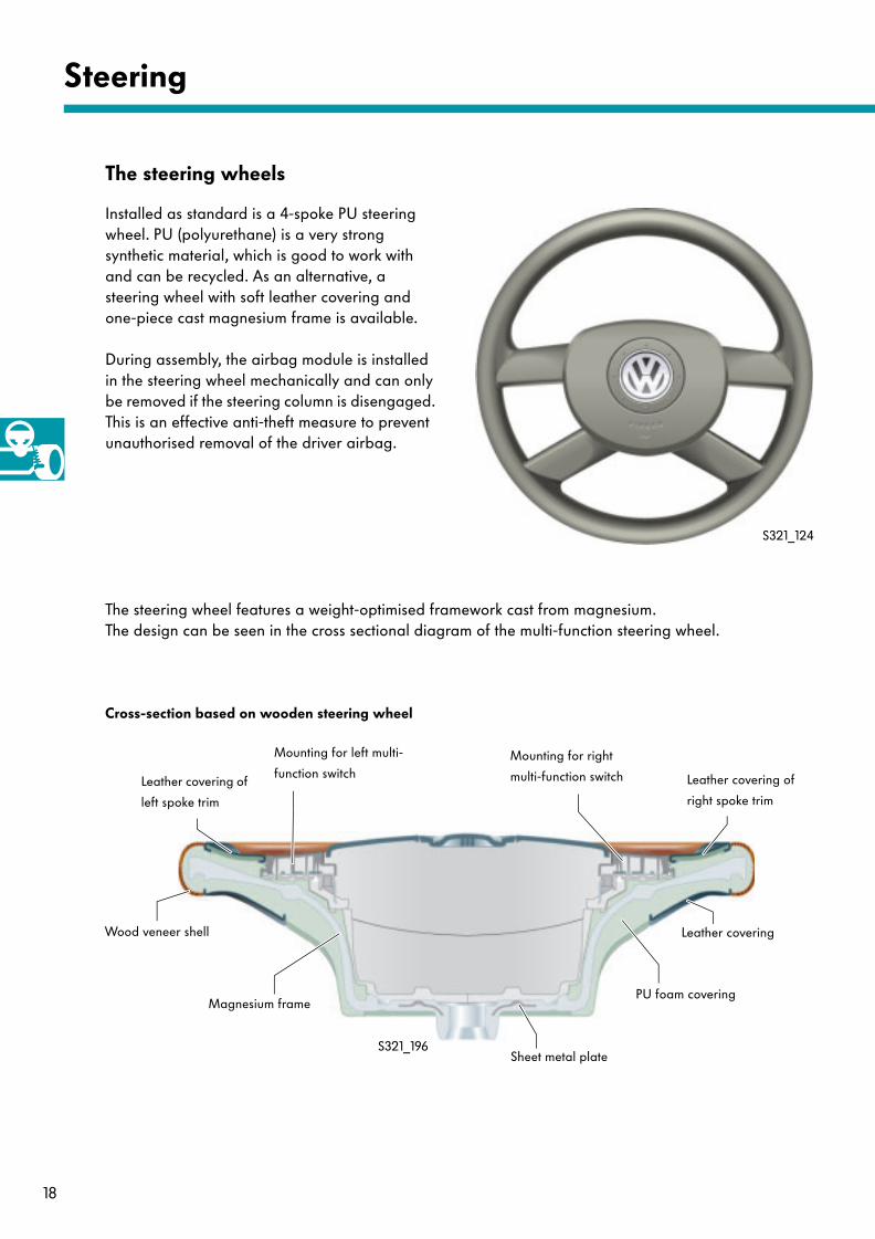
The steering wheels
Installed as standard is a 4-spoke PU steering wheel. PU (polyurethane) is a very strong synthetic material, which is good to work with and can be recycled. As an alternative, a steering wheel with soft leather covering and one-piece cast magnesium frame is available.
During assembly, the airbag module is installed in the steering wheel mechanically and can only be removed if the steering column is disengaged. This is an effective anti-theft measure to prevent unauthorised removal of the driver airbag.
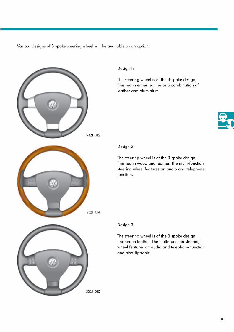
The steering wheel features a weight-optimised framework cast from magnesium. The design can be seen in the cross sectional diagram of the multi-function steering wheel.
S321_124
Magnesium framePU foam covering
Sheet metal plate
Wood veneer shell Leather covering
Mounting for right
multi-function switchLeather covering of
left spoke trim
Mounting for left multi-
function switch Leather covering of
right spoke trim
S321_196
Cross-section based on wooden steering wheel
19
Various designs of 3-spoke steering wheel will be available as an option.
Design 1:
The steering wheel is of the 3-spoke design, finished in either leather or a combination of leather and aluminium.
Design 2:
The steering wheel is of the 3-spoke design, finished in wood and leather. The multi-function steering wheel features an audio and telephone function.
Design 3:
The steering wheel is of the 3-spoke design, finished in leather. The multi-function steering wheel features an audio and telephone function and also Tiptronic.
S321_010
S321_014
S321_012
20
Steering
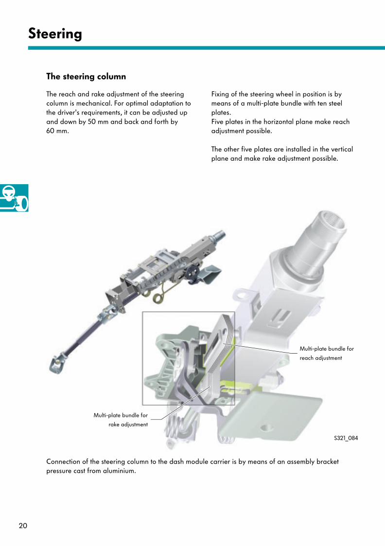
The steering column
The reach and rake adjustment of the steering column is mechanical. For optimal adaptation to the driver's requirements, it can be adjusted up and down by 50 mm and back and forth by 60 mm.
Connection of the steering column to the dash module carrier is by means of an assembly bracket pressure cast from aluminium.
Fixing of the steering wheel in position is by means of a multi-plate bundle with ten steel plates. Five plates in the horizontal plane make reach adjustment possible.
The other five plates are installed in the vertical plane and make rake adjustment possible.
S321_084
Multi-plate bundle for
reach adjustment
Multi-plate bundle for
rake adjustment
21
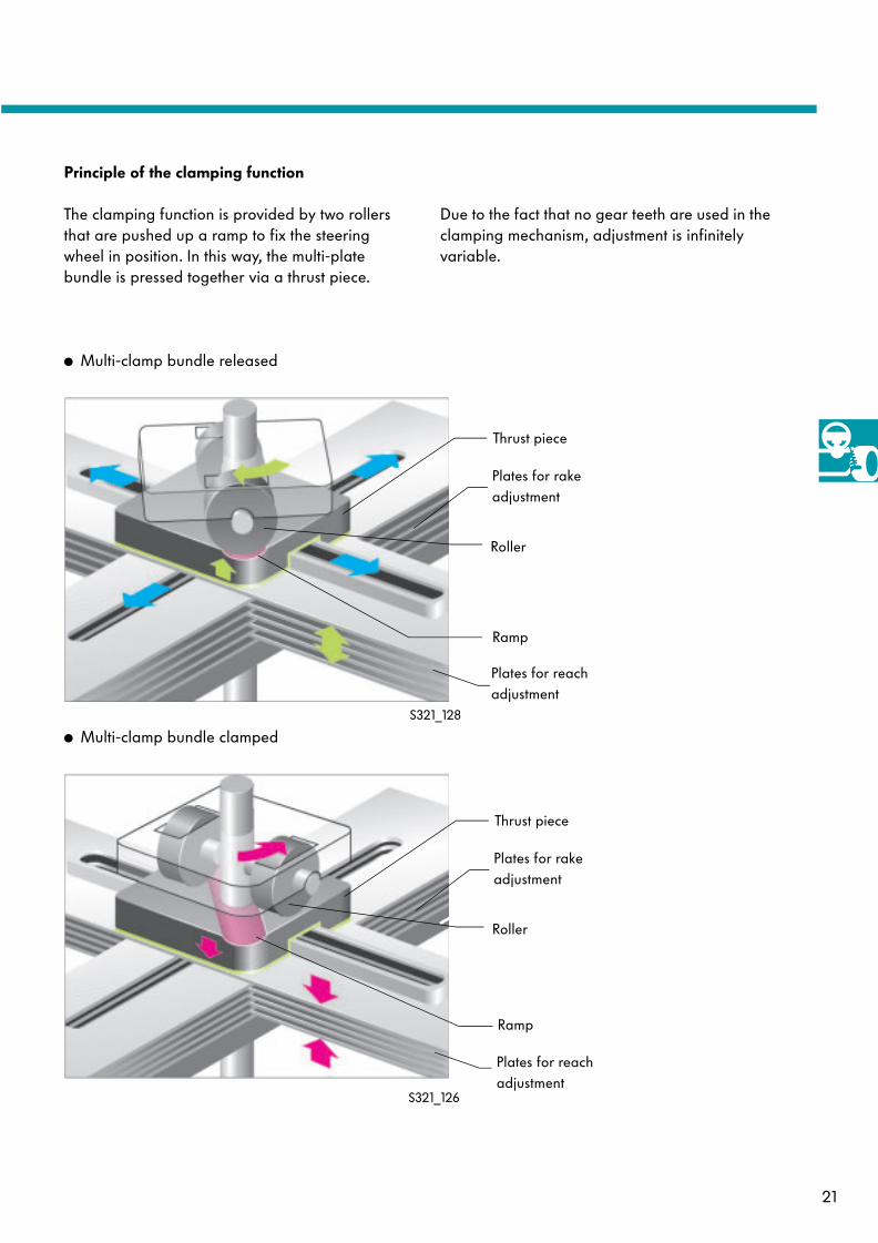
Principle of the clamping function
● Multi-clamp bundle released
● Multi-clamp bundle clamped
Thrust piece
Roller
Plates for reach adjustment
Plates for rake adjustment
Thrust piece
Roller
Plates for reach adjustment
Plates for rake adjustment
Ramp
S321_126
S321_128
The clamping function is provided by two rollers that are pushed up a ramp to fix the steering wheel in position. In this way, the multi-plate bundle is pressed together via a thrust piece.
Due to the fact that no gear teeth are used in the clamping mechanism, adjustment is infinitely variable.
Ramp
22
Steering
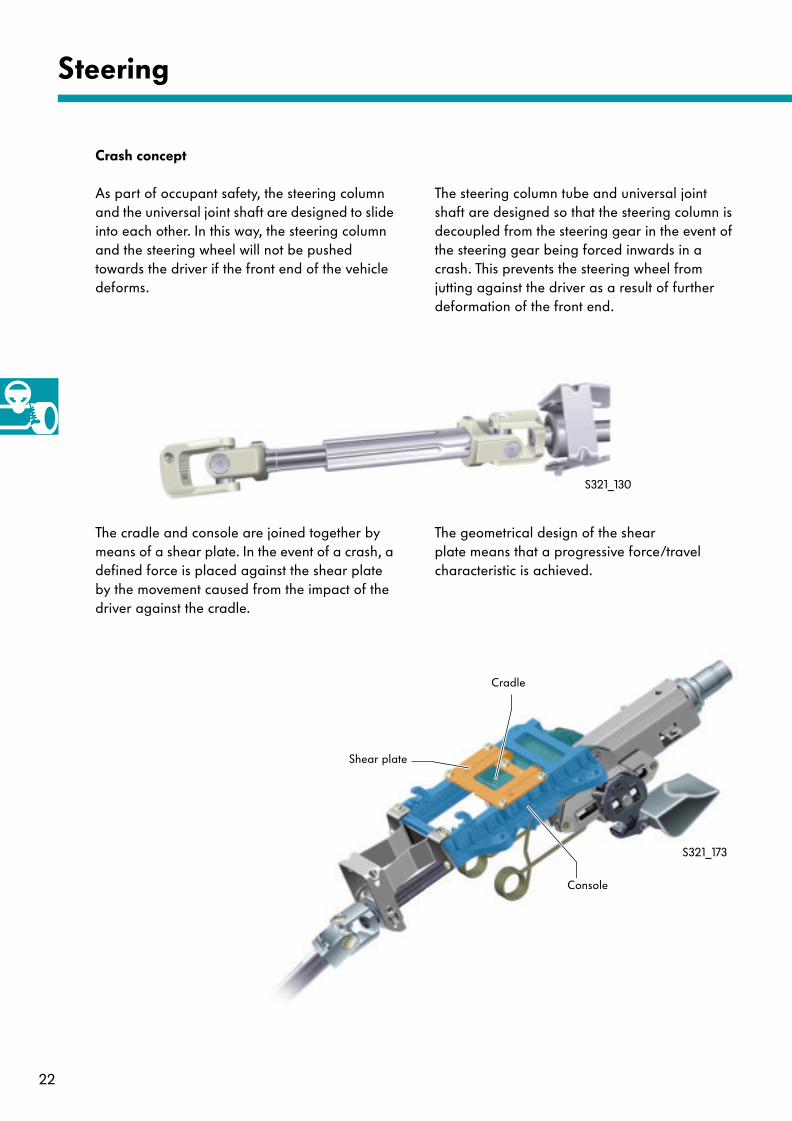
Crash concept
As part of occupant safety, the steering column and the universal joint shaft are designed to slide into each other. In this way, the steering column and the steering wheel will not be pushed towards the driver if the front end of the vehicle deforms.
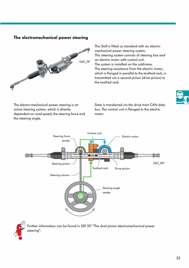
The cradle and console are joined together by means of a shear plate. In the event of a crash, a defined force is placed against the shear plate by the movement caused from the impact of the driver against the cradle.
Cradle
Shear plate
Console
S321_130
The steering column tube and universal joint shaft are designed so that the steering column is decoupled from the steering gear in the event of the steering gear being forced inwards in a crash. This prevents the steering wheel from jutting against the driver as a result of further deformation of the front end.
The geometrical design of the shear plate means that a progressive force/travelcharacteristic is achieved.
S321_173
23
The electromechanical power steering
The Golf is fitted as standard with an electro-mechanical power steering system. This steering system consists of steering box and an electric motor with control unit. The system is installed on the subframe. The steering assistance from the electric motor, which is flanged in parallel to the toothed rack, is transmitted via a second pinion (drive pinion) to the toothed rack.
S321_057
Steering angle
sender
Steering column
Steering force
sender
Control unitElectric motor
Toothed rack Drive pinion
Further information can be found in SSP 317 "The dual pinion electromechanical power steering".
The electro-mechanical power steering is an active steering system, which is directly dependent on road speed, the steering force and the steering angle.
Data is transferred via the drive train CAN data bus. The control unit is flanged to the electric motor.
S321_137
Steering pinion

24
Brake system
The brake system
Front wheel brake
Rear wheel brake
Brake servo
ESP unit
Handbrake
Brake lines
Brake cable
S321_155
The basis for good braking properties is provided by a newly designed brake system. The Golf is fitted as standard with the newest generation of ESP and brake assist system.
Overview
25
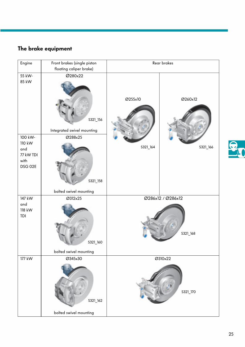
The brake equipment
Engine Front brakes (single pistonfloating caliper brake)
Rear brakes
55 kW-85 kW
Ø280x22
Integrated swivel mounting
Ø255x10 Ø260x12
100 kW-110 kW and 77 kW TDI with DSG 02E
Ø288x25
bolted swivel mounting
147 kWand 118 kW TDI
Ø312x25
bolted swivel mounting
Ø286x12 / Ø286x12
177 kW Ø345x30
bolted swivel mounting
Ø310x22
S321_156
S321_158
S321_160
S321_162
S321_168
S321_170
S321_164 S321_166
26
Brake system
The dual rate booster brake servo
In all left-hand drive vehicles, a 10" brake servo is installed. Right-hand drive vehicles are equipped with a tandem brake servo of 7/8" in dimension.
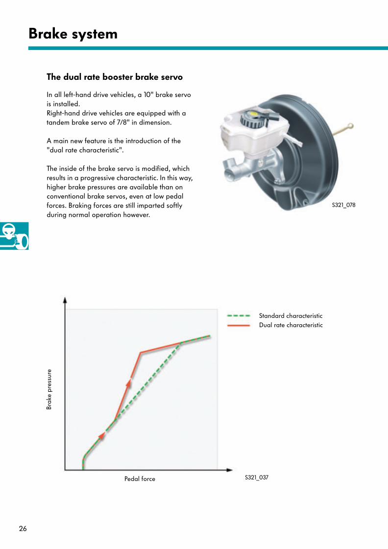
A main new feature is the introduction of the "dual rate characteristic".
The inside of the brake servo is modified, which results in a progressive characteristic. In this way, higher brake pressures are available than on conventional brake servos, even at low pedal forces. Braking forces are still imparted softly during normal operation however.
Pedal force
Brak
e pr
essu
re
Standard characteristicDual rate characteristic
S321_037
S321_078
27
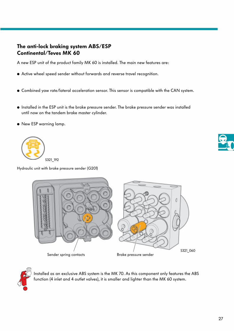
S321_060Brake pressure senderSender spring contacts
The anti-lock braking system ABS/ESP Continental/Teves MK 60
A new ESP unit of the product family MK 60 is installed. The main new features are:
● Active wheel speed sender without forwards and reverse travel recognition.
● Combined yaw rate/lateral acceleration sensor. This sensor is compatible with the CAN system.
● Installed in the ESP unit is the brake pressure sender. The brake pressure sender was installeduntil now on the tandem brake master cylinder.
● New ESP warning lamp.
Hydraulic unit with brake pressure sender (G201)
Installed as an exclusive ABS system is the MK 70. As this component only features the ABS function (4 inlet and 4 outlet valves), it is smaller and lighter than the MK 60 system.
S321_192
28
Brake system
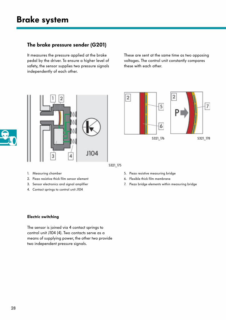
The brake pressure sender (G201)
It measures the pressure applied at the brake pedal by the driver. To ensure a higher level of safety, the sensor supplies two pressure signals independently of each other.
1. Measuring chamber
2. Piezo resistive thick film sensor element
3. Sensor electronics and signal amplifier
4. Contact springs to control unit J104
Electric switching
The sensor is joined via 4 contact springs to control unit J104 (4). Two contacts serve as a means of supplying power, the other two provide two independent pressure signals.
5. Piezo resistive measuring bridge
6. Flexible thick film membrane
7. Piezo bridge elements within measuring bridge
These are sent at the same time as two opposing voltages. The control unit constantly compares these with each other.
S321_175
S321_176 S321_178
29
As pressure increases, the length of the membrane (6) changes and also the piezo resistive measuring bridge (5) connected to it. This change in length imparts force on the piezo bridge elements in the measuring bridge (7), which alters the charge distribution within the piezo elements.
Function
The pressure sensor is monitored by the electronic control unit via both output signals. If both signals deviate from each other within the tolerance level, a fault is diagnosed by the control unit.
Self-diagnosis
With a change in the charge distribution, the electrical properties of the piezo bridge elementsalso change. These are proportional to the pressure and are transmitted as an amplified sensor signal to control unit J104.
Construction
The sensor works on the principle of piezo resistance. To do this, use is made of the change in conductivity of the materials from structural deformation. Four piezo resistive measuring elements, which are switched together to form a bridge (5), are installed on a membrane (6).
Piezo resistive measuring elements are resistors made from semi-conductor material. The function is similar to that of bi-metallic strips.
In the event of pressure sensor failure, the ESP function is reduced to ABS and EBD (electronic brake pressure distribution).
Effects of failure
30
Brake system
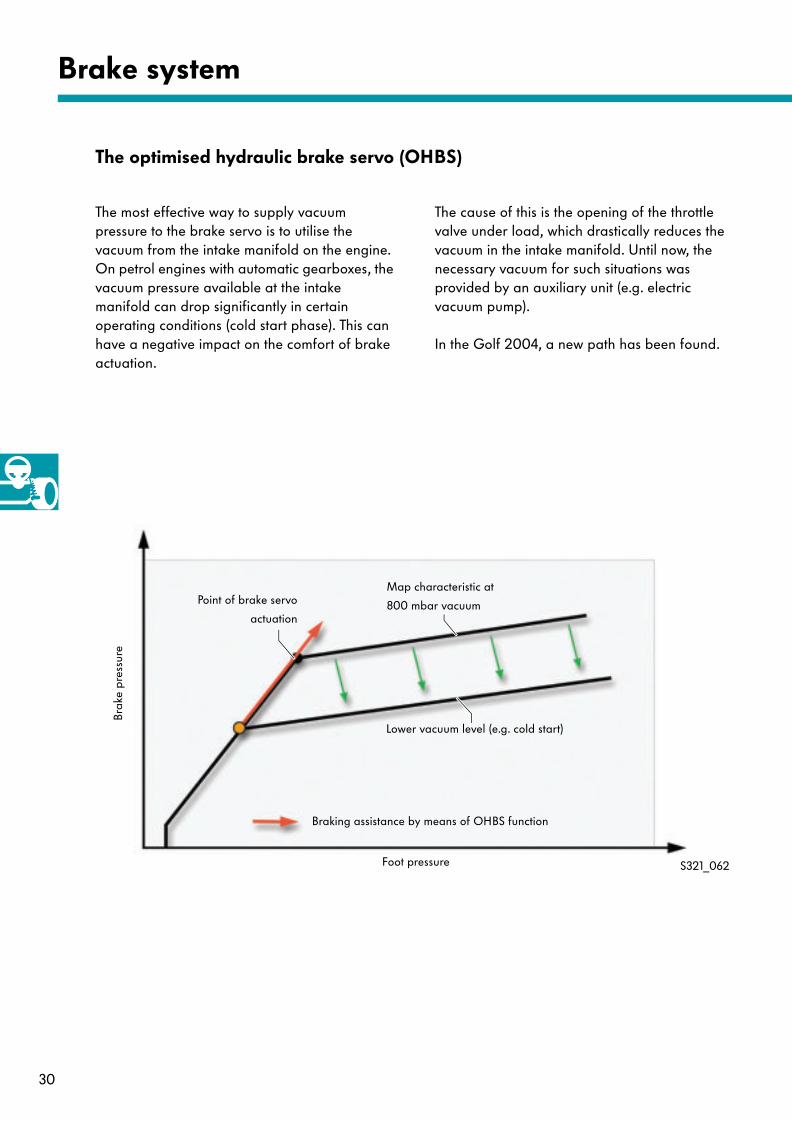
The optimised hydraulic brake servo (OHBS)
The most effective way to supply vacuum pressure to the brake servo is to utilise the vacuum from the intake manifold on the engine. On petrol engines with automatic gearboxes, the vacuum pressure available at the intake manifold can drop significantly in certain operating conditions (cold start phase). This can have a negative impact on the comfort of brake actuation.
The cause of this is the opening of the throttle valve under load, which drastically reduces the vacuum in the intake manifold. Until now, the necessary vacuum for such situations was provided by an auxiliary unit (e.g. electric vacuum pump).
In the Golf 2004, a new path has been found.
Brak
e pr
essu
re
Foot pressure
Point of brake servo
actuation
Map characteristic at
800 mbar vacuum
Lower vacuum level (e.g. cold start)
Braking assistance by means of OHBS function
S321_062
31
The loss of braking assistance, as a result of insufficient vacuum pressure, is balanced out with an active and controlled build-up of brake pressure from the ESP hydraulics. To enable this control, measurement of the pneumatic forces in both chambers of the brake servo (BS) is necessary. The pressure difference is a direct benchmark for the maximum amount of braking assistance available. If the pressure in both chambers is equaI, the point of brake servo actuation is reached. Thereafter, a further increase in braking force is only possible, without additional braking assistance, by an increase in foot pressure on the brake pedal.
Stored in the ESP control unit J104 is the specified map characteristic for the build-up of brake pressure, depending on the pressure difference in both servo chambers. If the intake manifold vacuum is insufficient, the point of actuation is reached even at brake pressure levels below the specified amount.
Function
If this is the case, a controlled build-up of brake pressure is initiated by the ESP hydraulics. Compared to conventional braking assistance, the driver will notice no difference here with regards to the force required at the brake pedal and braking comfort.
To enable the controlled build-up of brake pressure, the use of new solenoid valves is made to switch to ESP regulated mode.
The degree to which these valves is opened can be controlled on a time basis. In this way, the pressure patterns can be adapted to each situation.
32
Brake system
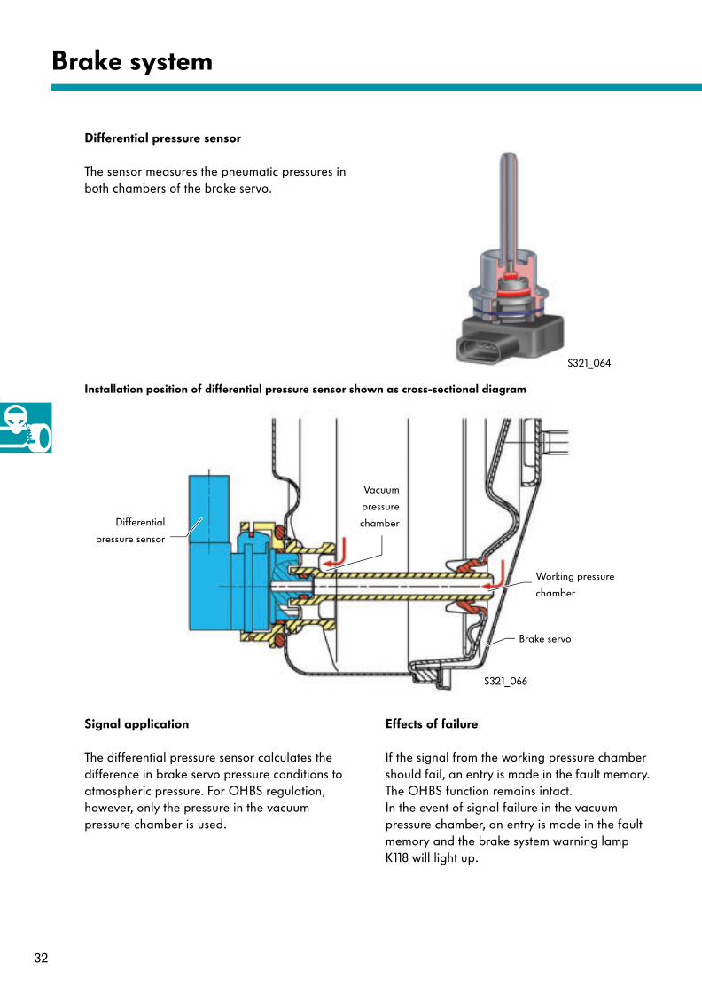
Differential pressure sensor
The sensor measures the pneumatic pressures in both chambers of the brake servo.
Vacuum
pressure
chamber
Working pressure
chamber
Installation position of differential pressure sensor shown as cross-sectional diagram
Differential
pressure sensor
Brake servo
S321_064
S321_066
Effects of failureSignal application
The differential pressure sensor calculates the difference in brake servo pressure conditions to atmospheric pressure. For OHBS regulation, however, only the pressure in the vacuum pressure chamber is used.
If the signal from the working pressure chamber should fail, an entry is made in the fault memory. The OHBS function remains intact. In the event of signal failure in the vacuum pressure chamber, an entry is made in the fault memory and the brake system warning lamp K118 will light up.
33
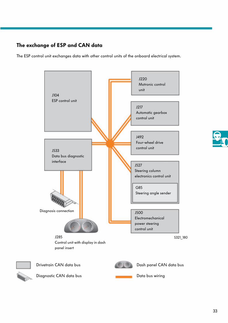
The exchange of ESP and CAN data
S321_180
The ESP control unit exchanges data with other control units of the onboard electrical system.
J104ESP control unit
J533 Data bus diagnostic interface
J220 Motronic control unit
Diagnosis connection
J285Control unit with display in dash panel insert
J217Automatic gearbox control unit
J492Four-wheel drive control unit
J527Steering column electronics control unit
G85Steering angle sender
J500Electromechanical power steering control unit
Drivetrain CAN data bus
Diagnostic CAN data bus
Dash panel CAN data bus
Data bus wiring
34
Brake system
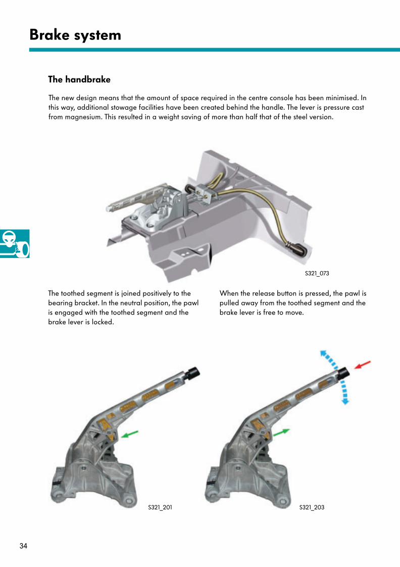
The handbrake
The new design means that the amount of space required in the centre console has been minimised. In this way, additional stowage facilities have been created behind the handle. The lever is pressure cast from magnesium. This resulted in a weight saving of more than half that of the steel version.
The toothed segment is joined positively to the bearing bracket. In the neutral position, the pawl is engaged with the toothed segment and the brake lever is locked.
When the release button is pressed, the pawl is pulled away from the toothed segment and the brake lever is free to move.
S321_073
S321_201 S321_203
35
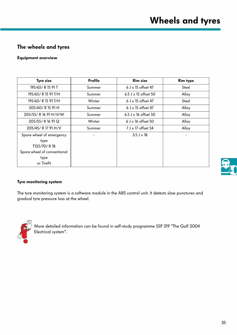
The wheels and tyres
Equipment overview
Tyre size Profile Rim size Rim type
195/65/ R 15 91 T Summer 6 J x 15 offset 47 Steel
195/65/ R 15 91 T/H Summer 6.5 J x 15 offset 50 Alloy
195/65/ R 15 91 T/H Winter 6 J x 15 offset 47 Steel
205/60/ R 15 91 H Summer 6 J x 15 offset 47 Alloy
205/55/ R 16 91 H/V/W Summer 6.5 J x 16 offset 50 Alloy
205/55/ R 16 91 Q Winter 6 J x 16 offset 50 Alloy
205/45/ R 17 91 H/V Summer 7 J x 17 offset 54 Alloy
Spare wheel of emergency type
T125/70/ R 18Spare wheel of conventional
typeor Tirefit
- 3.5 J x 18 -
Wheels and tyres
Tyre monitoring system
The tyre monitoring system is a software module in the ABS control unit. It detects slow punctures and gradual tyre pressure loss at the wheel.
More detailed information can be found in self-study programme SSP 319 "The Golf 2004 Electrical system".

36
The pedal cluster
The foot pedal cluster was adapted to the Golf. Accelerator pedal, clutch and brake actuation are of a modular design.
S321_087
Pedal cluster
To remove the accelerator pedal module, please use special tool T10238 or T10240.
The clutch position sender G476
Fitting location
The clutch position sender is clipped onto the master cylinder. This sender detects when the clutch pedal is actuated.
Signal application
With the clutch pedal actuated,
● the cruise control system is switched off and
● the amount of fuel injected is reduced brieflyto prevent gear change jolts.
Clutch pedal with clutch
position sender
S321_195
37
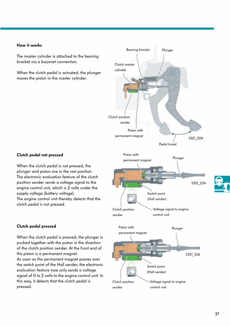
How it works
The master cylinder is attached to the bearing bracket via a bayonet connection.
When the clutch pedal is actuated, the plunger moves the piston in the master cylinder.
Clutch position
sender
Piston with
permanent magnet
Plunger
Pedal travel
S321_204
Bearing bracket
Clutch master
cylinder
Clutch pedal not pressed
When the clutch pedal is not pressed, the plunger and piston are in the rest position. The electronic evaluation feature of the clutch position sender sends a voltage signal to the engine control unit, which is 2 volts under the supply voltage (battery voltage). The engine control unit thereby detects that the clutch pedal is not pressed.
Clutch pedal pressed
When the clutch pedal is pressed, the plunger is pushed together with the piston in the direction of the clutch position sender. At the front end of the piston is a permanent magnet. As soon as the permanent magnet passes over the switch point of the Hall sender, the electronic evaluation feature now only sends a voltage signal of 0 to 2 volts to the engine control unit. In this way, it detects that the clutch pedal is pressed.
Piston with
permanent magnetPlunger
Switch point
(Hall sender)
S321_224
Clutch position
sender
Piston with
permanent magnetPlunger
Switch point
(Hall sender)
S321_226
Clutch position
sender
Voltage signal to engine
control unit
Voltage signal to engine
control unit
38
Pedal cluster
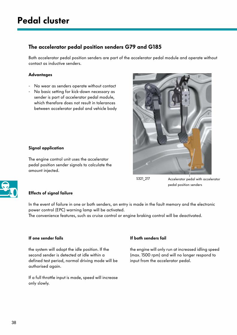
The accelerator pedal position senders G79 and G185
Both accelerator pedal position senders are part of the accelerator pedal module and operate without contact as inductive senders.
Signal application
The engine control unit uses the accelerator pedal position sender signals to calculate the amount injected.
Accelerator pedal with accelerator
pedal position senders
S321_217
the engine will only run at increased idling speed (max. 1500 rpm) and will no longer respond to input from the accelerator pedal.
Effects of signal failure
the system will adopt the idle position. If the second sender is detected at idle within a defined test period, normal driving mode will be authorised again.
If a full throttle input is made, speed will increase only slowly.
Advantages
- No wear as senders operate without contact- No basic setting for kick-down necessary as
sender is part of accelerator pedal module,which therefore does not result in tolerancesbetween accelerator pedal and vehicle body
In the event of failure in one or both senders, an entry is made in the fault memory and the electronic power control (EPC) warning lamp will be activated. The convenience features, such as cruise control or engine braking control will be deactivated.
If one sender fails If both senders fail
39
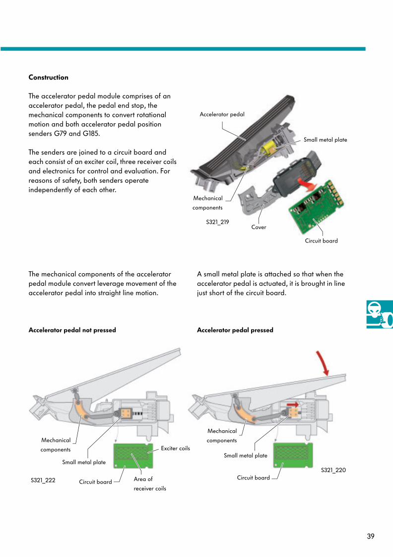
Exciter coils
Area of
receiver coils
The mechanical components of the accelerator pedal module convert leverage movement of the accelerator pedal into straight line motion.
A small metal plate is attached so that when the accelerator pedal is actuated, it is brought in line just short of the circuit board.
Mechanical
components
Small metal plate
Circuit board
S321_220
S321_222
Construction
The accelerator pedal module comprises of an accelerator pedal, the pedal end stop, the mechanical components to convert rotational motion and both accelerator pedal position senders G79 and G185.
The senders are joined to a circuit board and each consist of an exciter coil, three receiver coils and electronics for control and evaluation. For reasons of safety, both senders operate independently of each other.
Accelerator pedal
Circuit board
Mechanical
components
Cover
Small metal plate
S321_219
Accelerator pedal not pressed Accelerator pedal pressed
Circuit board
Mechanical
components
Small metal plate
40
Pedal cluster
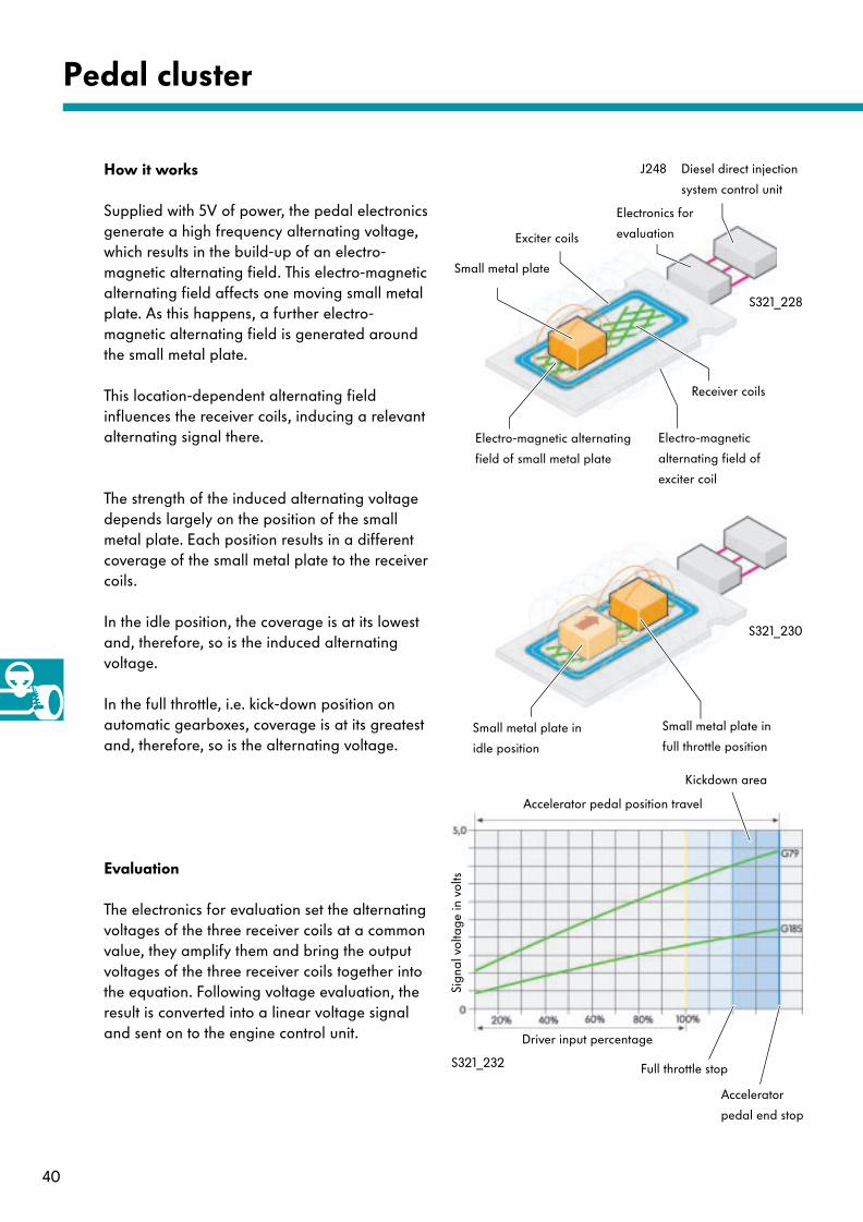
Supplied with 5V of power, the pedal electronics generate a high frequency alternating voltage, which results in the build-up of an electro-magnetic alternating field. This electro-magnetic alternating field affects one moving small metal plate. As this happens, a further electro-magnetic alternating field is generated around the small metal plate.
This location-dependent alternating field influences the receiver coils, inducing a relevant alternating signal there.
The electronics for evaluation set the alternating voltages of the three receiver coils at a common value, they amplify them and bring the output voltages of the three receiver coils together into the equation. Following voltage evaluation, the result is converted into a linear voltage signal and sent on to the engine control unit.
The strength of the induced alternating voltage depends largely on the position of the small metal plate. Each position results in a different coverage of the small metal plate to the receiver coils.
In the idle position, the coverage is at its lowest and, therefore, so is the induced alternating voltage.
In the full throttle, i.e. kick-down position on automatic gearboxes, coverage is at its greatest and, therefore, so is the alternating voltage.
Exciter coils
Small metal plate
Receiver coils
S321_232
J248 Diesel direct injection
system control unit
Small metal plate in
idle position
Electro-magnetic
alternating field of
exciter coil
How it works
Evaluation
Accelerator pedal position travel
Driver input percentage
Kickdown area
Full throttle stop
Accelerator
pedal end stop
Electronics for
evaluation
Electro-magnetic alternating
field of small metal plate
Small metal plate in
full throttle position
S321_228
S321_230
Sign
al v
olta
ge in
vol
ts
41
Service
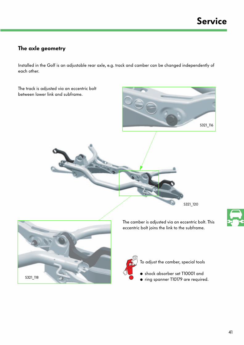
Installed in the Golf is an adjustable rear axle, e.g. track and camber can be changed independently of each other.
The camber is adjusted via an eccentric bolt. This eccentric bolt joins the link to the subframe.
The track is adjusted via an eccentric bolt between lower link and subframe.
S321_120
The axle geometry
S321_116
To adjust the camber, special tools
● shock absorber set T10001 and ● ring spanner T10179 are required.S321_118
42
Service
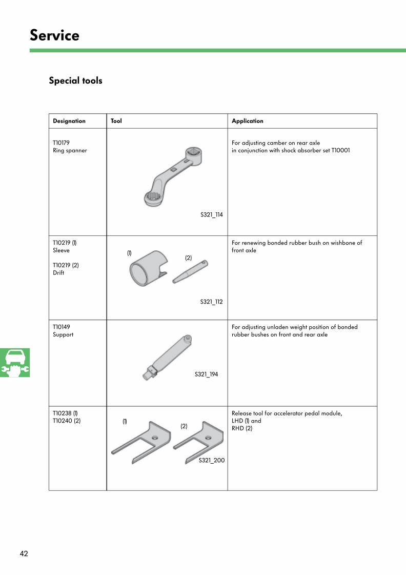
Special tools
Designation Tool Application
T10179Ring spanner
For adjusting camber on rear axle in conjunction with shock absorber set T10001
T10219 (1)Sleeve
T10219 (2)Drift
For renewing bonded rubber bush on wishbone of front axle
T10149Support
For adjusting unladen weight position of bonded rubber bushes on front and rear axle
T10238 (1)T10240 (2)
Release tool for accelerator pedal module, LHD (1) and RHD (2)
(1)(2)
S321_200
(1)(2)
S321_114
S321_112
S321_194
43
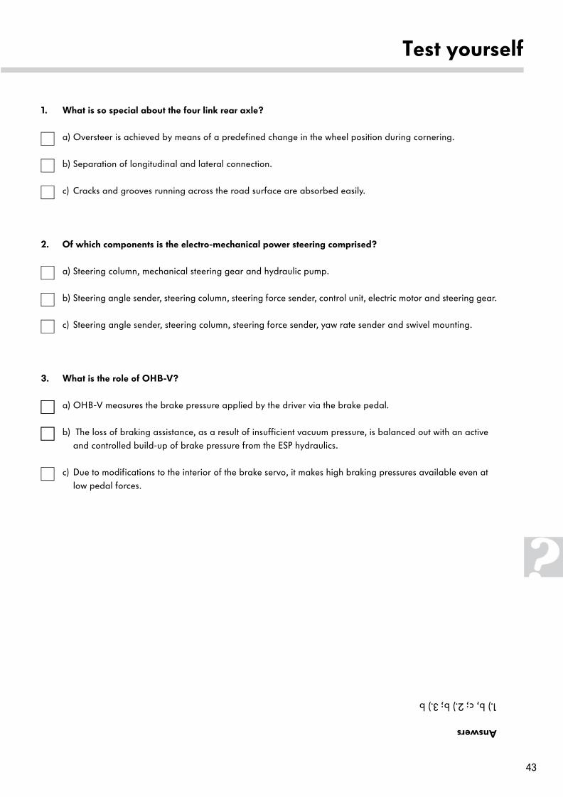
Answers
1.) b, c; 2.) b; 3.) b
Test yourself
1. What is so special about the four link rear axle?
a) Oversteer is achieved by means of a predefined change in the wheel position during cornering.
b) Separation of longitudinal and lateral connection.
c) Cracks and grooves running across the road surface are absorbed easily.
2. Of which components is the electro-mechanical power steering comprised?
a) Steering column, mechanical steering gear and hydraulic pump.
b) Steering angle sender, steering column, steering force sender, control unit, electric motor and steering gear.
c) Steering angle sender, steering column, steering force sender, yaw rate sender and swivel mounting.
3. What is the role of OHB-V?
a) OHB-V measures the brake pressure applied by the driver via the brake pedal.
b) The loss of braking assistance, as a result of insufficient vacuum pressure, is balanced out with an active and controlled build-up of brake pressure from the ESP hydraulics.
c) Due to modifications to the interior of the brake servo, it makes high braking pressures available even at low pedal forces.
321
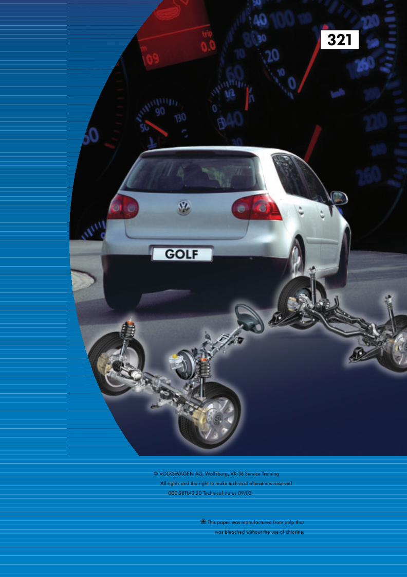
© VOLKSWAGEN AG, Wolfsburg, VK-36 Service Training
All rights and the right to make technical alterations reserved
000.2811.42.20 Technical status 09/03
❀ This paper was manufactured from pulp that
was bleached without the use of chlorine.