Embed Size (px)
Citation preview

284
LightCurtain
Sensors
SSP-T200series
● Picking sensor for checking andinstruction of removing parts from bin
● Thinness of 13 mm achievedwith rigid metal case
● Large work operation indicator(job light)
● Faulty work operation indicator(fault light) is provided
● 4 types are available fordifferent sizes of parts bins
● Requiring no synchronization lineAsynchronous method employed, eliminating needfor synchronization line
■ TypeDetectionmethod
Detectingdistance
No. of light axes
Detectingwidth
51013165
101316
100mm225mm300mm375mm100mm225mm300mm375mm
Set modelNo.
Light axisinterval
Detectingobject
Through-beam type
Mounting brackets are separately available.
2m max.
SSP-T205SSP-T210SSP-T213SSP-T216SSP-T205-JSSP-T210-JSSP-T213-JSSP-T216-J
25mm
Opaqueobject of φ35mmmin.
Connection
Permanently
attached cord
Permanently
attached cord
with connector
■ Special mounting brackets (optional)Model
SSP-B1
SSP-B2
Model
Flat plate type
L-shaped plate type
Remarks
Two brackets in one set
(with M4 x 12 sems screws with washers and nuts)● Two sets are required for transmitter and receiver.
■ Cord with connector (optional)Model
FAC-D4R2
FAC-D4R5
Shape, etc.
M12 straight 4-core cord / 2 m (common to transmitter and receiver)
M12 straight 4-core cord / 5 m (common to transmitter and receiver)
Light curtain sensors for picking
PH SYSTEMS - www.phsystems.be - [email protected]
285
LightCurtain
Sensors
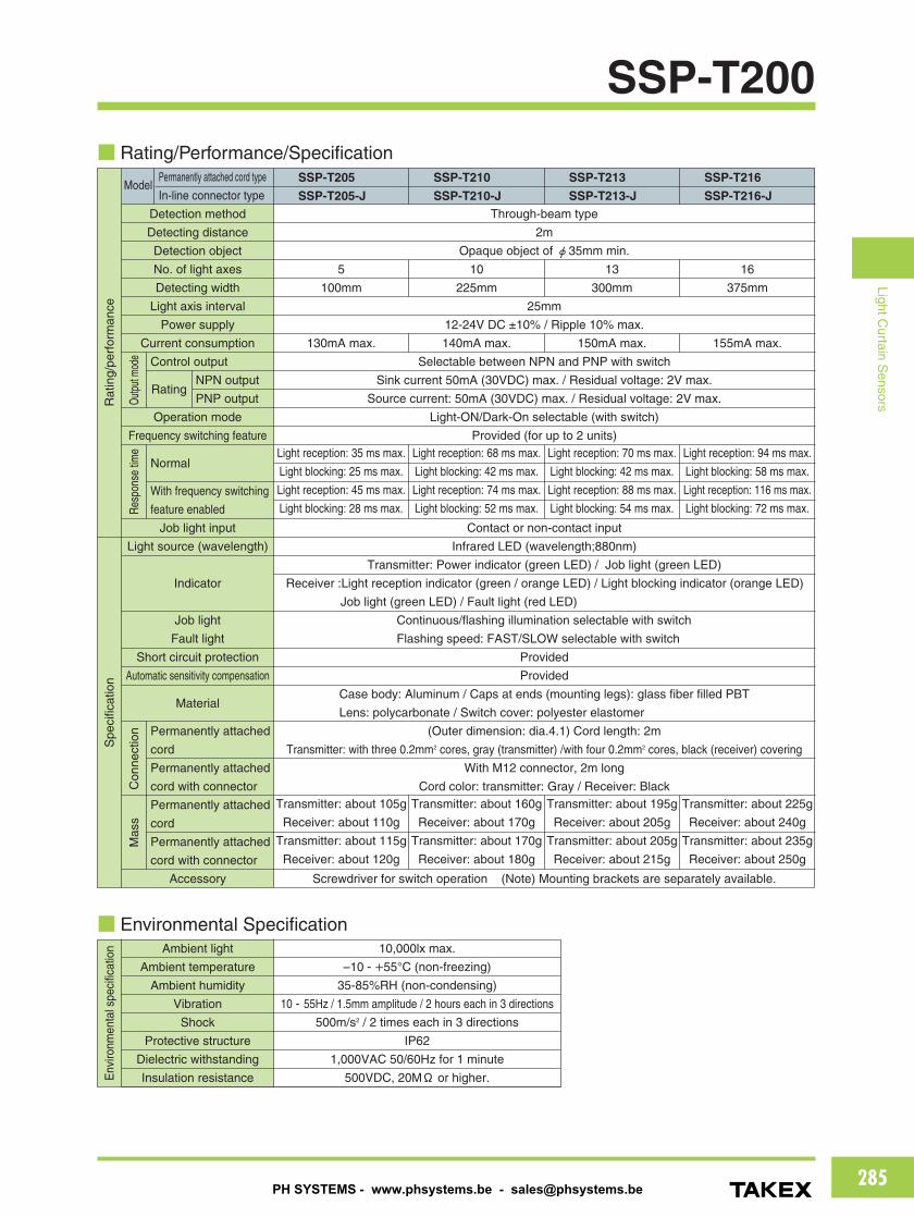
SSP-T200■ Rating/Performance/Specification
Rat
ing/
perf
orm
ance
Permanently attached cord type
In-line connector typeModel
Detection method
Detecting distance
Detection object
No. of light axes
Detecting width
Light axis interval
Power supply
Current consumption
Control output
NPN output
PNP output
Operation mode
Frequency switching feature
Normal
With frequency switching
feature enabled
Job light input
Light source (wavelength)
Indicator
Job light
Fault light
Short circuit protection
Automatic sensitivity compensation
Material
Permanently attached
cord
Permanently attached
cord with connector
Permanently attached
cord
Permanently attached
cord with connector
Accessory
SSP-T205
SSP-T205-J
SSP-T210
SSP-T210-JThrough-beam type
2m
Opaque object of φ35mm min.
10
225mm
5
100mm
13
300mm
16
375mm
Transmitter: about 105g
Receiver: about 110g
Transmitter: about 115g
Receiver: about 120g
Transmitter: about 160g
Receiver: about 170g
Transmitter: about 170g
Receiver: about 180g
130mA max.
Light reception: 35 ms max.
Light blocking: 25 ms max.
Light reception: 45 ms max.
Light blocking: 28 ms max.
Light reception: 68 ms max.
Light blocking: 42 ms max.
Light reception: 74 ms max.
Light blocking: 52 ms max.
Light reception: 70 ms max.
Light blocking: 42 ms max.
Light reception: 88 ms max.
Light blocking: 54 ms max.
Light reception: 94 ms max.
Light blocking: 58 ms max.
Light reception: 116 ms max.
Light blocking: 72 ms max.
140mA max.
Transmitter: about 195g
Receiver: about 205g
Transmitter: about 205g
Receiver: about 215g
150mA max.
Transmitter: about 225g
Receiver: about 240g
Transmitter: about 235g
Receiver: about 250g
155mA max.
25mm
12-24V DC ±10% / Ripple 10% max.
Selectable between NPN and PNP with switch
Sink current 50mA (30VDC) max. / Residual voltage: 2V max.
Source current: 50mA (30VDC) max. / Residual voltage: 2V max.
Light-ON/Dark-On selectable (with switch)
Provided (for up to 2 units)
Contact or non-contact input
Infrared LED (wavelength;880nm)
Provided
Provided
Screwdriver for switch operation (Note) Mounting brackets are separately available.
Transmitter: Power indicator (green LED) / Job light (green LED)
Receiver :Light reception indicator (green / orange LED) / Light blocking indicator (orange LED)
Job light (green LED) / Fault light (red LED)
Case body: Aluminum / Caps at ends (mounting legs): glass fiber filled PBT
Lens: polycarbonate / Switch cover: polyester elastomer
(Outer dimension: dia.4.1) Cord length: 2m
Transmitter: with three 0.2mm2 cores, gray (transmitter) /with four 0.2mm2 cores, black (receiver) covering
With M12 connector, 2m long
Cord color: transmitter: Gray / Receiver: Black
Continuous/flashing illumination selectable with switch
Flashing speed: FAST/SLOW selectable with switch
SSP-T213
SSP-T213-J
SSP-T216
SSP-T216-J
Spe
cific
atio
n
■ Environmental Specification
Env
ironm
enta
lspe
cific
atio
n Ambient light
Ambient temperature
Ambient humidity
Vibration
Shock
Protective structure
Dielectric withstanding
Insulation resistance
10,000lx max.
–10 - +55°C (non-freezing)
35-85%RH (non-condensing)
10 - 55Hz / 1.5mm amplitude / 2 hours each in 3 directions
500m/s2 / 2 times each in 3 directions
IP62
1,000VAC 50/60Hz for 1 minute
500VDC, 20MΩ or higher.
Outp
utm
ode
Resp
onse
time
Con
nect
ion
Mas
s
Rating
PH SYSTEMS - www.phsystems.be - [email protected]
286
LightCurtain
Sensors
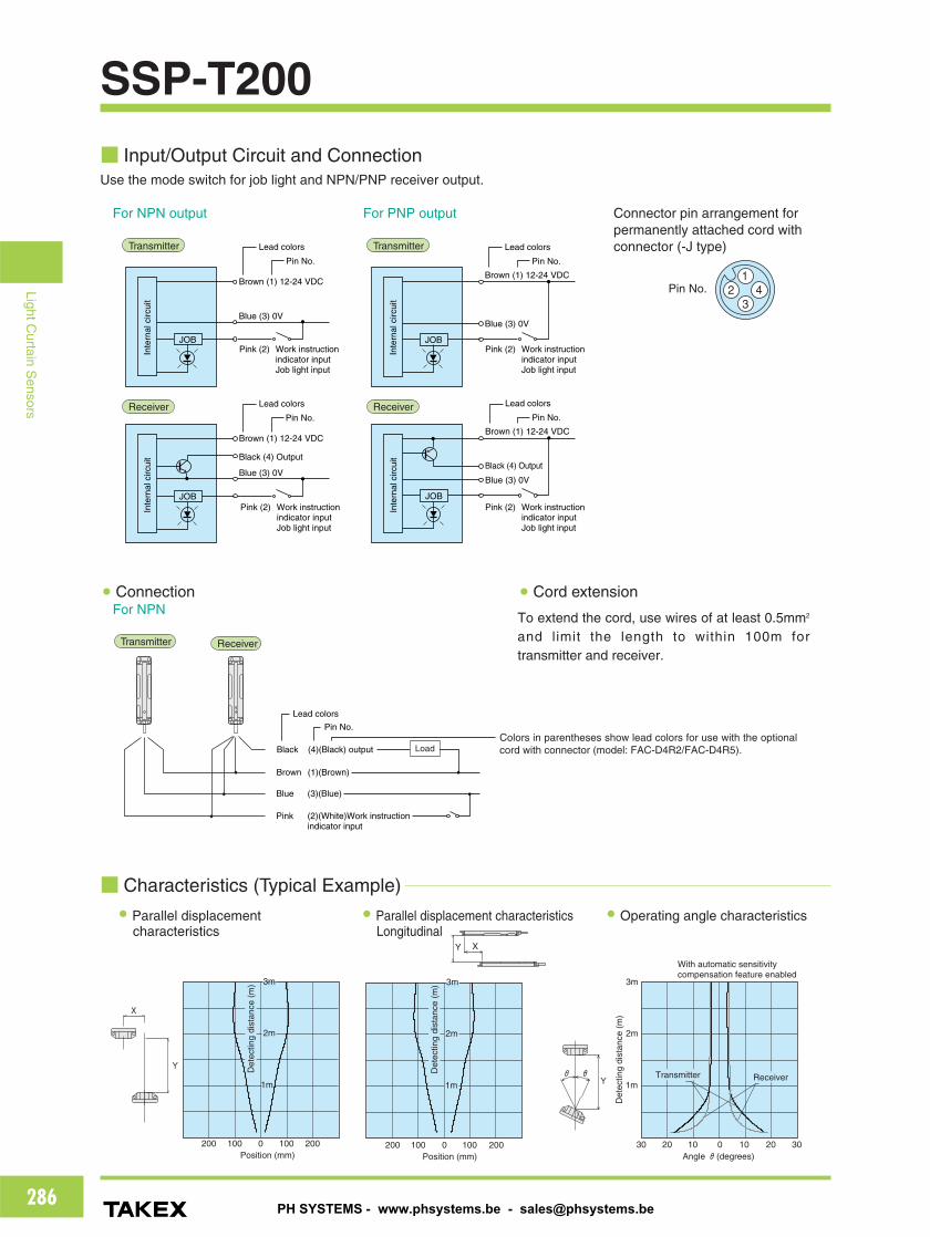
SSP-T200■ Input/Output Circuit and Connection
■ Characteristics (Typical Example)
2m
1m
X
Y
100 2000200 100Position (mm)
2m
1m
Det
ectin
g di
stan
ce (
m)
Det
ectin
g di
stan
ce (
m)
2001000100Position (mm)
200
Y X
Det
ectin
g di
stan
ce (
m)
With automatic sensitivitycompensation feature enabled
ReceiverTransmitterθY
θ
3020Angle θ(degrees)
01020 10
3m
2m
1m
30
3m 3m
● Parallel displacementcharacteristics
● Parallel displacement characteristicsLongitudinal
● Operating angle characteristics
● Cord extension● Connection
To extend the cord, use wires of at least 0.5mm2
and limit the length to within 100m fortransmitter and receiver.
Colors in parentheses show lead colors for use with the optionalcord with connector (model: FAC-D4R2/FAC-D4R5).
Use the mode switch for job light and NPN/PNP receiver output.
For NPN output
For NPN
For PNP output Connector pin arrangement forpermanently attached cord withconnector (-J type)
Brown (1) 12-24 VDC
Blue (3) 0V
Inte
rnal
circ
uit
Lead colors
Pin No.
JOB
Brown (1) 12-24 VDC
Black (4) Output
Blue (3) 0V
Inte
rnal
circ
uit
Lead colors
Pin No.
JOB
Brown (1) 12-24 VDC
Blue (3) 0V
Inte
rnal
circ
uit
Lead colors
Pin No.
JOB
Brown (1) 12-24 VDC
Black (4) Output
Blue (3) 0V
Inte
rnal
circ
uit
Lead colors
Pin No.
JOB
Transmitter
Receiver
Transmitter
Receiver
Pink (2) Work instruction indicator inputJob light input
Pink (2) Work instruction indicator inputJob light input
Pink (2) Work instruction indicator inputJob light input
Pink (2) Work instruction indicator inputJob light input
Transmitter Receiver
Brown
Pink
Black
Blue
(1)(Brown)
(2)(White)Work instruction indicator input
(4)(Black) output
(3)(Blue)
Lead colors
Pin No.
Load
14
32Pin No.
PH SYSTEMS - www.phsystems.be - [email protected]
287
LightCurtain
Sensors
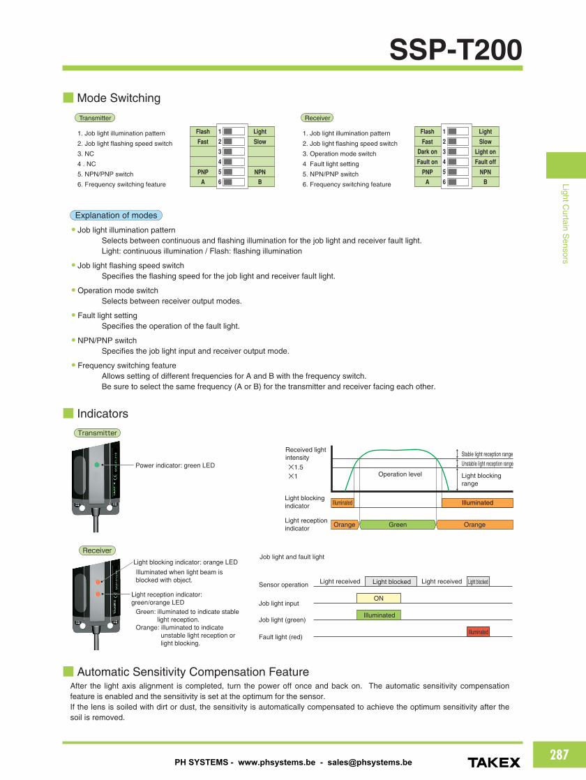
SSP-T200■Mode Switching
■ Indicators
ReceiverTransmitter
1. Job light illumination pattern
2. Job light flashing speed switch
3. NC
4 . NC
5. NPN/PNP switch
6. Frequency switching feature
1. Job light illumination pattern
2. Job light flashing speed switch
3. Operation mode switch
4 Fault light setting
5. NPN/PNP switch
6. Frequency switching feature
2
3
4
5
6
1Flash
Fast
PNP
A
Light
Light on
Slow
NPN
B
Dark on
Fault on Fault off
2
3
4
5
6
1Flash
Fast
PNP
A
Light
Slow
NPN
B
Explanation of modes
● Job light illumination patternSelects between continuous and flashing illumination for the job light and receiver fault light.Light: continuous illumination / Flash: flashing illumination
● Job light flashing speed switchSpecifies the flashing speed for the job light and receiver fault light.
● Operation mode switchSelects between receiver output modes.
● Fault light settingSpecifies the operation of the fault light.
● NPN/PNP switchSpecifies the job light input and receiver output mode.
● Frequency switching featureAllows setting of different frequencies for A and B with the frequency switch.Be sure to select the same frequency (A or B) for the transmitter and receiver facing each other.
IlluminatedIlluminated
Illuminated
Illuminated
Light blocking indicator
Light blocked Light blocked
Light reception indicator
Light received Light received
Orange OrangeGreen
Sensor operation
Job light input
Job light (green)
Fault light (red)
ON
Operation level
Received light intensity
×1.5×1
Stable light reception range
Unstable light reception range
Light blocking range
Job light and fault light
Transmitter
Receiver
Power indicator: green LED
Light reception indicator: green/orange LED
Light blocking indicator: orange LED
Illuminated when light beam is blocked with object.
Green: illuminated to indicate stable light reception.
Orange: illuminated to indicate unstable light reception or light blocking.
■ Automatic Sensitivity Compensation FeatureAfter the light axis alignment is completed, turn the power off once and back on. The automatic sensitivity compensationfeature is enabled and the sensitivity is set at the optimum for the sensor.If the lens is soiled with dirt or dust, the sensitivity is automatically compensated to achieve the optimum sensitivity after thesoil is removed.
PH SYSTEMS - www.phsystems.be - [email protected]
288
LightCurtain
Sensors
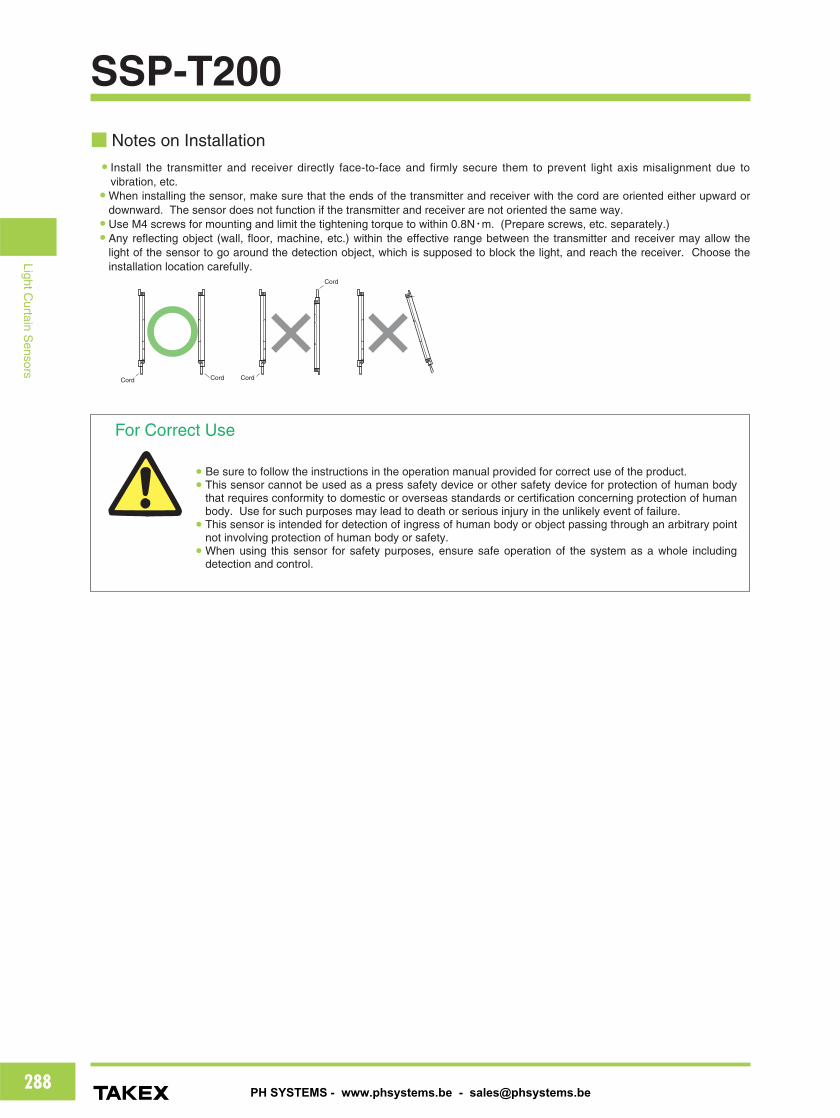
■ Notes on Installation● Install the transmitter and receiver directly face-to-face and firmly secure them to prevent light axis misalignment due to
vibration, etc.● When installing the sensor, make sure that the ends of the transmitter and receiver with the cord are oriented either upward or
downward. The sensor does not function if the transmitter and receiver are not oriented the same way.● Use M4 screws for mounting and limit the tightening torque to within 0.8N・m. (Prepare screws, etc. separately.)● Any reflecting object (wall, floor, machine, etc.) within the effective range between the transmitter and receiver may allow the
light of the sensor to go around the detection object, which is supposed to block the light, and reach the receiver. Choose theinstallation location carefully.
For Correct Use
● Be sure to follow the instructions in the operation manual provided for correct use of the product.● This sensor cannot be used as a press safety device or other safety device for protection of human body
that requires conformity to domestic or overseas standards or certification concerning protection of humanbody. Use for such purposes may lead to death or serious injury in the unlikely event of failure.
● This sensor is intended for detection of ingress of human body or object passing through an arbitrary pointnot involving protection of human body or safety.
● When using this sensor for safety purposes, ensure safe operation of the system as a whole includingdetection and control.
SSP-T200
Cord Cord Cord
Cord
PH SYSTEMS - www.phsystems.be - [email protected]

289
LightCurtain
Sensors
SSP-T200
L
10
20
40
223
18 6
10
10 20
2-φ4.6×6 elongate hole 2-φ4.6×6 elongate hole4-φ4.6
4-φ4.6
6
26
259
48
18
50
5
φ14.9
φ6
3430
1816
10
6 11
23
Mode switch cover
Model N L1 L2
SSP-T205 5 130 140
SSP-T210 10 255 265
SSP-T213 13 330 340
SSP-T216 16 405 415
25×(N-1)
18
32
L251
57
L1
413
Transmitter Job light: work operation indicator (green LED)
ReceiverJob light: work operation indicatorFault light: faulty work operation indicator (red LED)
Transmitter: power indicator (green LED)
Receiver: light blocking indicator (orange LED)
Receiver: light reception indicator (green/orange LED)
4-φ4.5×5.5 elongate hole
Cord length: 2m φ4.1
■ Dimensions (in mm)
SSP-T200 series
M12 connector(DC type)
2000
Model N L1 L2
SSP-T205-J 5 130 140
SSP-T210-J 10 255 265
SSP-T213-J 13 330 340
SSP-T216-J 16 405 415
Mode switch cover
25×(N-1)
18
32
L251
57
L1
413
Receiver Job light: work operation indicatorFault light: faulty work operation indicator (red LED)
Transmitter: power indicator (green LED)
Receiver: light blocking indicator (orange LED)
Receiver: light reception indicator (green/orange LED)
Transmitter Job light: work operation indicator (green LED)
4-φ4.5×5.5 elongate holes
SSP-T200-J series
● Optional parts Model:SSP-B1Flat plate type
Model:SSP-B2L-shaped plate type
Mounting brackets● Two types of mounting brackets are
available.● Two brackets are required to mount
either of the transmitter andreceiver. Mounting brackets are available insets of two.
● Four sems screws with M4 x 12washers and nuts are provided.
Cord with connector
Model:FAC-D4R2(L:2m)FAC-D4R5(L:5m)
PH SYSTEMS - www.phsystems.be - [email protected]


![Scanned with CamScanner2.336.7278-1 ssp r] 2.137.438.67 ssp 3.539.747 ssp pb 9.188.097 sds pe 3.941.456 ssds pb 2.962.728 ssp pb 3.470.194 ssp pb 3.714.010 ssp pb 28.250.988-4 detran](https://img.pdfslide.us/doc/110x75/5f66e8908127b2003314bb43/scanned-with-23367278-1-ssp-r-213743867-ssp-3539747-ssp-pb-9188097-sds.jpg)