Embed Size (px)
Citation preview
SS
P-e
n-C
/E -
06/2
017
- Due
to p
rodu
ct a
nd s
tand
ards
evo
lutio
n, c
hara
cter
istic
s an
d di
men
sion
s ar
e lik
ely
to c
hang
e.
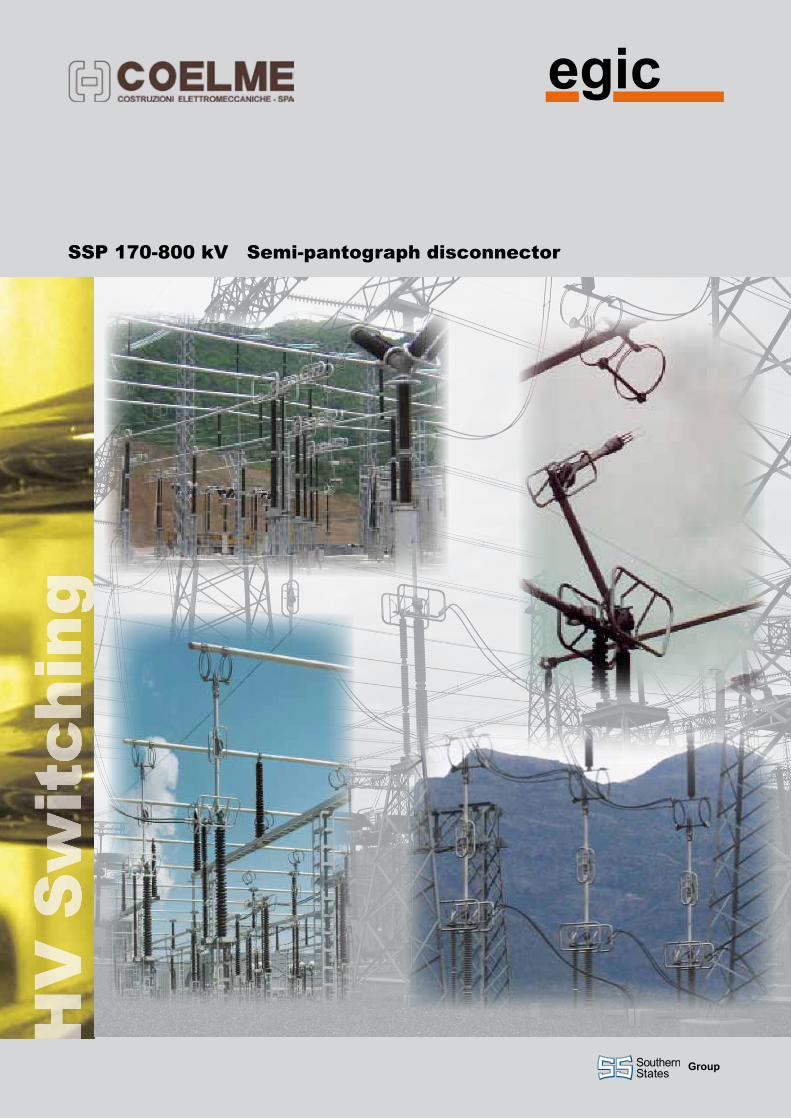
SSP 170-800 kV Semi-pantograph disconnector
group

Our range of semi-pantograph disconnectors is designed to ensure the best performances and reliability, which are the result of our 60-year old experience.Over 100,000 disconnectors installed in more than 100 countries worldwide are the guarantee of best-buys.
The SSP disconnector is composed of three poles operated simultaneously either by a single operating mechanism and mechanical linkages between the poles, or by one single operating mechanism for each pole.
The semi-pantograph is generally used as a “busbar disconnector”, since it allows very reduced phase-to-phase clearances for feeder/transformer bays and stands just beneath the main busbar: no other AIS solution is more compact and efficient.
The reliability of the SSP is ensured by the physical separation of the mechanical and the electrical functions. When short-time current flows through it, the electro-dynamic forces increase the contact pressure of fingers on the fixed contact bar.
The insulating columns used for the SSP comply with the IEC or the ANSI Standards. Special heights and creepage distances are also available upon request.
Like all our models, the SSP complies with the latest international standards (IEC, ANSI), but can also be customised according to customers’ particular specifications.
The SSP uses the same technology as that of the OH disconnector (horizontal “knee-type”): both lines distinguish themselves for their simplicity and strength and most components are the same, which allows a better management of spare part stocks and a better training of the assembling workers.
Integrated earthing blades are available for mounting on each pole, with the same short-time current withstand capability.
The earthing switch is actuated by the same types of operating mechanisms as the disconnector, either manually or electrically, either single- or 3-pole. It can be electrically and/or mechanically interlocked with the main switch.
We know how
The SSP semi-pantographdisconnector
Earthing switch

The base-frame supports the post insulator on which the moving arm is bolted. The rotating insulating rod (driving insulator), which operates the arm, is directly connected with the operating mechanism.
From the open position, the insulating rod 1 rotates, to transmit the movement to the lower half-arm through a bevel gear and a crank-rod system. The upper half-arm movement is controlled by a rack-pinion system housed inside the elbow. Both half-arms raise together till closing the jaw at the upper end on the fixed contact ; the closing of the jaw, controlled by a rod inside the upper half-harm, only occurs in the last phase of the operation, thus giving the disconnector a contact zone suitable for all flexible or rigid busbar systems. After reaching the final closed position, the moving arm is locked by the passing of a dead-point, preventing any accidental opening.
The flat HV terminals are shown in the next page figure; customised terminals are also available upon request.
The arm of each pole is made of hard-drawn aluminium tubes, with silver-plated copper fingers bolted at the upper end (jaw).
According to the rated voltage, the current path at hinged points is ensured by copper braids or by self-cleaning, maintenance-free rotary contacts, with silver-plated “fingers”, individually loaded by stainless steel springs.
The arm is ideally balanced, by a spring housed inside its lower half, to ensure a smooth low energy demanding motion.
The fixed contact consists of a silver-plated copper tube, hung to the upper busbar through flexible aluminium loops ensuring the best alignment, even in case of unexpected motion of the upper busbar. This also allows for an easy adjustment of the position of the fixed contact, whatever the height of the upper busbar. The connector to the upper busbar can be supplied upon request.
All the exposed hardware of the main circuit is made of stainless steel.
The HV terminals are made of robust aluminium-alloy plates. Where necessary, suitable shields protect the main circuit from the corona effect.
The base-frame is made of hot-dip galvanized steel. The bearings are sealed and guaranteed to ensure maintenance-free operation for the whole life of the equipment.
The whole design and manufacturing process is ruled by ISO 9001 certified procedures, to guarantee a perfect reproducibility of performances from type-testing to the series production.
1
3
Operating principle
Construction features
2
3
4 5
1
2
3
4
5

B
F
A
C D
L
M
9 Ø16
4 ØK
45
12545
45
ER
45S
SP
-en-
C/E
- 06
/201
7 - D
ue to
pro
duct
and
sta
ndar
ds e
volu
tion,
cha
ract
eris
tics
and
dim
ensi
ons
are
likel
y to
cha
nge.
Due to lifetime greased or self-lubricated hinges and to self-wiping contacts, the maintenance of SSP metallic parts is ensured by their own motion.
The use of corrosion-free or treated materials for all components ensures an exceptional reliability over many years of service.
The mechanical endurance performance exceeds the IEC standard requirements.
Upon request, the disconnector can be equipped with a bus-transfer current switching device compliant with IEC 62271-102 (Annex B).
The integrated earthing switch can also be fitted with optional induced current switching devices compliant with IEC 62271-102 (Annex C).
For operation under severe ice conditions (up to 20 mm), ice shields are available for protection of the equipment (where needed).
COELMEVia G. Galilei, 1/2 - 30036 Santa Maria di Sala (VE) - ItaliaTel.: +39 041 486022 - Fax: +39 041 486909E-Mail: [email protected], www.coelme-egic.com
EgiC60b, rue L. et R. Desgrand - 69625 Villeurbanne CEDEX - FranceTel.: +33 4 72 66 20 70 - Fax: +33 4 72 39 08 65E-Mail: [email protected], www.coelme-egic.com
Rated voltage Ur (kV) 170 245 362 420 550 800
Rated power-frequency withstand voltage
TE Ud (kV) 325 460 450 520 620 830
AID Ud (kV) 375 530 520 610 800 1150
Rated lightning impulse withstand voltage
TE Up (kVp) 750 1050 1175 1425 1550 2100
AID Up (kVp) 860 1200 1175 (+205) 1425 (+240) 1550 (+315) 2100 (+455)
Rated switching impulse withstand voltage
TE Us (kVp) - - 950 1050 1175 1550
AID Us (kVp) - - 800 (+295) 900 (+345) 900 (+450) 1175(+650)
TE: To Earth AID : Across the Isolating Distance
Rated continuous current ir (A) up to 4000 IEC / ANSI (depending on rated voltage)
Rated short-time withstand current ik (kA) up to 63 / 3s (depending on rated current)
Rated peak withstand current ip (kAp) up to 160 (depending on rated current)
Dimensions (mm) A 300 680 920 920 920 890
B 4235 5640 7350 7825 8750 11850
C 1100 1730 2585 2585 2885 3650
D 670 655 640 640 640 750
E 1925 2525 3130 3560 3860 5204
F (adjustable) from 800 to 1000
L 180 180 320 320 320 320
M 230 230 330 330 330 330
K 18 L 40 18 L 40 20 L 40 20 L 40 20 L 40 20 L 40
R 1700 2300 2900 3350 3650 5300
The values in the table refer to IEC standards, unless explicit reference to ANSI is made; for missing ANSI ratings, refer to C37.32Ratings and dimensions
Reliability and maintenance
Optional devices

![GLOBAL STANDARD Page 1 of 52 GSM001 MV RMU … RMU WITH SWITCH-DISCONNECTOR Rev. 00 10/07/2014 Rated voltage [kV] 24 36 Rated insulation level . MV RMU WITH SWITCH-DISCONNECTOR GSM001](https://img.pdfslide.us/doc/110x75/5b0741567f8b9a5c308e195d/global-standard-page-1-of-52-gsm001-mv-rmu-rmu-with-switch-disconnector-rev-00.jpg)