Embed Size (px)
Citation preview
SSE-F3548S/SSE-F3548SR
IP Unicast Routing Overview
User’s Guide
Revision 1.0
Supermicro SSE-F3548S/SSE-F3548SR IP Unicast Overview User’s Guide 2
The information in this USER’S GUIDE has been carefully reviewed and is believed to be accurate. The
vendor assumes no responsibility for any inaccuracies that may be contained in this document, makes
no commitment to update or to keep current the information in this manual, or to notify any person
organization of the updates. Please Note: For the most up-to-date version of this manual, please see our
web site at www.supermicro.com.
Super Micro Computer, Inc. (“Supermicro”) reserves the right to make changes to the product described
in this manual at any time and without notice. This product, including software, if any, and
documentation may not, in whole or in part, be copied, photocopied, reproduced, translated or reduced
to any medium or machine without prior written consent.
DISCLAIMER OF WARRANTY ON SOFTWARE AND MATERIALS. You expressly acknowledge and agree that
use of the Software and Materials is at your sole risk. FURTHERMORE, SUPER MICRO COMPUTER INC.
DOES NOT WARRANT OR MAKE ANY REPRESENTATIONS REGARDING THE USE OR THE RESULTS OF THE
USE OF THE SOFTWARE OR MATERIALS IN TERMS OF THEIR CORRECTNESS, ACCURACY, RELIABILITY, OR
OTHERWISE. NO ORAL OR WRITTEN INFORMATION OR ADVICE GIVEN BY SUPER MICRO COMPUTER INC.
OR SUPER MICRO COMPUTER INC. AUTHORIZED REPRESENTATIVE SHALL CREATE A WARRANTY OR IN
ANY WAY INCREASE THE SCOPE OF THIS WARRANTY. SHOULD THE SOFTWARE AND/OR MATERIALS
PROVE DEFECTIVE, YOU (AND NOT SUPER MICRO COMPUTER INC. OR A SUPER MICRO COMPUTER INC.
AUTHORIZED REPRESENTATIVE) ASSUME THE ENTIRE COST OF ALL NECESSARY SERVICE, REPAIR, OR
CORRECTION.
LIMITATION OF LIABILITY. UNDER NO CIRCUMSTANCES INCLUDING NEGLIGENCE, SHALL SUPER MICRO
COMPUTER INC. BE LIABLE FOR ANY INCIDENTAL, SPECIAL, OR CONSEQUENTIAL DAMAGES THAT RESULT
FROM THE USE OR INABILITY TO USE THE SOFTWARE OR MATERIALS, EVEN IF SUPER MICRO COMPUTER
INC. OR A SUPER MICRO COMPUTER INC. AUTHORIZED REPRESENTATIVE HAS BEEN ADVISED OF THE
POSSIBILITY OF SUCH DAMAGES.
Any disputes arising between manufacturer and customer shall be governed by the laws of Santa Clara
County in the State of California, USA. The State of California, County of Santa Clara shall be the
exclusive venue for the resolution of any such disputes. Super Micro's total liability for all claims will not
exceed the price paid for the hardware product. Manual Revision 1.0 Release Date: 3/2/2020 Unless you request and receive written permission from Super Micro Computer, Inc., you may not copy any part of this document. Information in this document is subject to change without notice. Other products and companies referred to herein are trademarks or registered trademarks of their respective companies or mark holders. Copyright © 2020 by Super Micro Computer, Inc. All rights reserved. Printed in the United States of America
Supermicro SSE-F3548S/SSE-F3548SR IP Unicast Overview User’s Guide 3
Document Revision History
Date Revision Description
03/2/2020 1.0 Initial document.
Supermicro SSE-F3548S/SSE-F3548SR IP Unicast Overview User’s Guide 4
Contents 1 IP Unicast Routing Overview..................................................................................................................................... 7
2 RIP ........................................................................................................................................................................................ 8
2.1 Network .............................................................................................................................. 8
2.2 Neighbor ............................................................................................................................. 8
2.3 Metric .................................................................................................................................. 8
2.4 Route tag ............................................................................................................................. 9
2.5 Split Horizon ........................................................................................................................ 9
2.6 Summarization .................................................................................................................... 9
2.7 Authentication .................................................................................................................. 10
2.8 Security ............................................................................................................................. 10
2.9 Passive Interface ............................................................................................................... 10
2.10 Inter-packet delay ............................................................................................................. 10
2.11 Re-transmission ................................................................................................................ 10
2.12 Timers ............................................................................................................................... 10
2.13 Default route ..................................................................................................................... 11
2.14 RIP Configuration .............................................................................................................. 11
2.14.1 Default RIP Configuration ................................................................................................. 11
2.14.2 Enabling RIP ...................................................................................................................... 12
2.14.3 RIP Neighbor ..................................................................................................................... 12
2.14.4 Interface Parameters ........................................................................................................ 12
2.14.5 Additional Parameters ...................................................................................................... 14
2.14.6 RIP Configuration Example ............................................................................................... 16 3 OSPF ................................................................................................................................................................................... 19
3.1 Neighbor & DR .................................................................................................................. 20
3.2 LSA..................................................................................................................................... 20
3.3 Area ................................................................................................................................... 21
3.4 OSPF Router Types ............................................................................................................ 22
3.5 Types of routes ................................................................................................................. 23
3.6 Default route ..................................................................................................................... 23
3.7 Metric ................................................................................................................................ 23
3.8 Router Id ........................................................................................................................... 23
Supermicro SSE-F3548S/SSE-F3548SR IP Unicast Overview User’s Guide 5
3.9 Priority .............................................................................................................................. 24
3.10 Route Summarization ....................................................................................................... 24
3.11 Authentication .................................................................................................................. 24
3.12 Timers ............................................................................................................................... 24
3.13 Virtual Link ........................................................................................................................ 24
3.14 Passive Interface ............................................................................................................... 25
3.15 Demand Circuit ................................................................................................................. 25
3.16 Network Type .................................................................................................................... 25
3.17 OSPF Configuration ........................................................................................................... 26
3.17.1 OSPF Default Configuration .............................................................................................. 26
3.17.2 Enabling OSPF ................................................................................................................... 26
3.17.3 OSPF Neighbor .................................................................................................................. 27
3.17.4 Area Parameters ............................................................................................................... 27
3.17.5 Interface Parameters ........................................................................................................ 30
3.17.6 OSPF Configuration Example ............................................................................................ 32 4 BGP ..................................................................................................................................................................................... 36
4.1 Router ID ........................................................................................................................... 37
4.2 Speaker and Peer .............................................................................................................. 37
4.3 Autonomous System (AS) ................................................................................................. 38
4.4 Aggregate Addresses ........................................................................................................ 38
4.5 Route Reflection ............................................................................................................... 38
4.6 Confederation ................................................................................................................... 39
4.7 Attributes .......................................................................................................................... 39
4.7.1 Multi-Exit Discriminator (MED) Attribute ......................................................................... 39
4.7.2 Local Preference Attribute ................................................................................................ 39
4.7.3 Next-Hop Attribute ........................................................................................................... 39
4.7.4 Community Attribute ........................................................................................................ 39
4.7.5 Cluster ID ........................................................................................................................... 40 4.8 Filters ................................................................................................................................ 40
4.9 Overlapping Routes........................................................................................................... 40
4.10 Synchronization ................................................................................................................ 40
4.11 BGP Path selection ............................................................................................................ 41
Supermicro SSE-F3548S/SSE-F3548SR IP Unicast Overview User’s Guide 6
4.12 Timers ............................................................................................................................... 41
4.13 Route dampening.............................................................................................................. 41
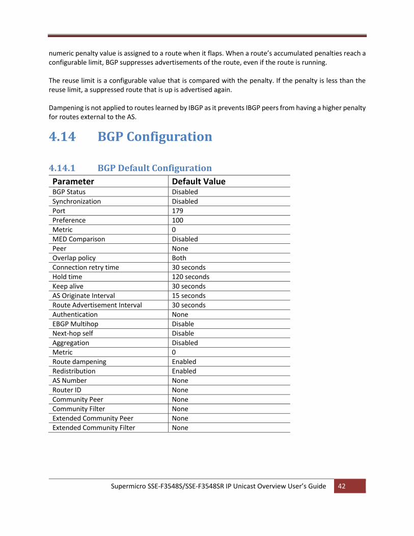
4.14 BGP Configuration............................................................................................................. 42
4.14.1 BGP Default Configuration ................................................................................................ 42
4.14.2 Enabling BGP ..................................................................................................................... 43
4.14.3 BGP Peer ........................................................................................................................... 43
4.14.4 Confederation ................................................................................................................... 44
4.14.5 Attributes .......................................................................................................................... 45
4.14.6 Route Reflection ............................................................................................................... 47
4.14.7 Route Dampening ............................................................................................................. 48
4.14.8 Other Parameters ............................................................................................................. 49
4.14.9 BGP Configuration Example .............................................................................................. 50 Contacting Supermicro ........................................................................................................................................................ 57
Supermicro SSE-F3548S/SSE-F3548SR IP Unicast Overview User’s Guide 7
1 IP Unicast Routing Overview Layer 3 switches can route packets in three different ways: • Default routing: Traffic with an unknown destination is sent to a default destination, usually specified by a default route configuration.
• Static routes: Static unicast routing forwards packets from predetermined ports through a single path into and out of a network. Static routing is secure and uses little bandwidth, but does not automatically respond to changes in the network, such as link failures, and hence may result in unreachable destinations. As networks grow, static routing configuration becomes labor-intensive.
• Dynamically Routing protocol: Dynamic routing protocols are used by routers to dynamically calculate the best route for forwarding traffic. There are two types of dynamic routing protocols:
Distance-vector protocols create/maintain routing tables with distance values of network
resources, and periodically update these tables to the neighbor routers. Distance-vector protocols
use one or a series of metrics for calculating the best routes. These protocols are easy to configure
and use. Distance-vector protocols supported by Supermicro switches are Routing Information
Protocol (RIP), which uses a single distance metric (cost) to determine the best path and Border
Gateway Protocol (BGP), which adds a path vector mechanism.
Link-state protocols create/maintain a complex database of network topology, based on the
exchange of link-state advertisements (LSAs) between routers. LSAs are triggered by an event in
the network, which speeds up the convergence time due to topology changes. Link-state
protocols require greater bandwidth and more resources than distance-vector protocols.
Supermicro switches support Open Shortest Path First (OSPF) link-state protocol.
Routing in the Internet is divided into two parts – fine-grained topological detail of connected segments of the Internet is managed with interior routing protocols (such as RIP or OSPF), while the interconnection of these segments, or “autonomous systems” is managed by an inter-domain routing protocol (such as Border Gateway Protocol, or BGP).
Administrative distance is a rating of the trustworthiness of a routing information source, an integer between 0 and 255, with a higher value meaning a lower trust rating. An administrative distance of 255 indicates the routing information should be ignored.
Redistribution is a process of passing the routing information from one routing domain to another. The purpose of redistribution is to provide full IP connectivity between different routing domains and to provide redundant connectivity, i.e. backup paths between routing domains. Routing domain is a set of routers running the same routing protocol. Redistribution process is performed by border routers – i.e. routers belonging to more than one routing domain. Supermicro switches allow redistribution of routes
Supermicro SSE-F3548S/SSE-F3548SR IP Unicast Overview User’s Guide 8
from/to RIP to/from other Unicast Routing Protocols, like OSPF. Differences in routing protocol characteristics, such as metrics, administrative distance, classful and classless capabilities can effect redistribution.
2 RIP Routing Information Protocol (RIP) is a distance-vector routing protocol that uses hop count (the number of routers) to determine the best way to a remote network. RIP sends the complete routing table out to all active interfaces every 30 seconds.
Supermicro switches support both RIPv1 and RIPv2. RIPv1 is a classful routing protocol that does not include the subnet mask with the network address in routing updates, which causes problems in discontiguous subnets or networks that use Variable-Length Subnet Masking (VLSM). RIPv2 is a classless routing protocol so subnet masks are included in the routing updates, making RIPv2 more compatible with modern routing environments.
RIP (Routing Information Protocol) is a widely-used protocol for managing router information within a
self-contained network such as a corporate local area network (LAN) or an interconnected group of such
LANs. RIP is considered an effective solution for small homogeneous networks. RIP is not suited for larger,
more complicated networks since the transmission of the entire routing table every 30 seconds increases
network traffic.
2.1 Network
Supermicro switches provide user configuration of the network IP address that run RIP. The network number specified must not contain any subnet information. RIP routing updates are sent and received only through interfaces on this network.
2.2 Neighbor
By default RIPv2 will send multicast updates out all interfaces specified within the range of the network command. Supermicro switches allow neighbor configuration that enables the switch to send unicast updates to that neighbor out the respected link. Multicast updates are also sent through the same link.
2.3 Metric
RIP uses a single routing metric (hop count) to measure the distance between the source and a destination network. Each hop in a path from source to destination is assigned a hop count value, which is typically 1. When a router receives a routing update that contains a new or changed destination network entry, the
Supermicro SSE-F3548S/SSE-F3548SR IP Unicast Overview User’s Guide 9
router adds 1 to the metric value indicated in the update and enters the network in the routing table. RIP routing is limited to 15 hops. A metric of 16 hops identifies unreachable network.
2.4 Route tag
Route tags are supported in RIP version 2. This functionality allows for routes to be distinguished from internal routes to external redistributed routes from EGP protocols.
2.5 Split Horizon
Routers connected to broadcast-type IP networks use the split-horizon mechanism to reduce routing loops, especially when links are broken. Split horizon blocks information about routes from being advertised by a router on any interface from which that information originated.
Supermicro switches support the following two mechanisms that help ensure the reachability of routes:
Split horizon -- This mechanism omits routes learned from one neighbor in updates sent to that neighbor. Split horizon minimizes routing overhead, but may cause slower convergence.
Split horizon with poison reverse -- This mechanism includes routes learned from one neighbor in updates sent to that neighbor. However, it sets the metric to 16, which avoids loop. Poison reverse speeds up convergence, but it increases routing overhead.
2.6 Summarization
In large internetworks, hundreds, or even thousands, of network addresses can exist. It is often problematic for routers to maintain this volume of routes in their routing tables. Route summarization also called route aggregation or supernetting helps reduce the number of routes that a router must maintain as a series of network numbers are represented by a single summary address.
Route summarization is most effective within a subnetted environment when the network addresses are in contiguous blocks in powers of 2. Summarization results in less CPU, memory, and bandwidth usage.
Routing protocols summarize or aggregate routes based on shared network numbers within the network. RIPv2 supports route summarization based on subnet addresses, including VLSM addressing. RIPv1 automatically summarize routes on the classful network boundary only.
If more than one entry in the route summary matches a particular destination, the longest prefix match in the routing table is used.
Supermicro SSE-F3548S/SSE-F3548SR IP Unicast Overview User’s Guide 10
NOTE: If split horizon is enabled, neither autosummary nor interface IP summary addresses is advertised.
2.7 Authentication
RIP Version 1 does not support authentication. RIP Version 2 packets supports RIP authentication on an interface. The key chain and the set of keys that can be used on the interface should be specified for authentication.
2.8 Security
RIP supports the following two security mechanisms that prevent unauthorized routers from forming adjacencies:
• Simple text password: This method transmits simple passwords in clear text.
• MD5 authentication (For RIPv2 only): This mechanism provides more protection than a simple
password and has a greater probability of detecting hostile messages.
2.9 Passive Interface
Passive interfaces are used to suppress routing updates. These interfaces can be used to allow an interface to receive updates but prevent the interface from sending advertisements.
2.10 Inter-packet delay
By default, RIP implementation in Supermicro switches does not add delay between packets during a multiple-packet RIP update transmission. If a high-end router is sending packets to a low-speed router, inter-packet delay of RIP updates must be configured, in the range of 8 to 50 milliseconds.
2.11 Re-transmission
Supermicro switches support retransmission of Update Request packet or unacknowledged Update response packet. User can specify the timeout interval and the maximum number of retransmissions of the update request and update response packets. During retries, if no response is received then the routes through the next hop router are marked unreachable.
2.12 Timers
RIP uses the following timers to maintain routing tables:
Supermicro SSE-F3548S/SSE-F3548SR IP Unicast Overview User’s Guide 11
Update timer: Routers within an autonomous system exchange routing information through periodic RIP updates. The update timer controls the frequency of these updates. Expiration timer: RIP expects an update every 30 seconds from its neighbors. If it does not receive an update in that time, RIP waits for a specified expiration time before declaring a route invalid. Triggered update timer: When routes change, Supermicro switch sends a RIP update almost immediately instead of waiting for its regular update message. This helps to speed up network convergence. The triggered update timer is set to wait for 5 seconds to avoid a storm of triggered updates.
2.13 Default route
RIP has a built in feature in which allows it to advertise a default route to its direct neighbors which will propagate throughout the entire RIP routing domain. The default route can be configured by the user. Utilizing this type of configuration reduces the effort required to configure a static default route on each and every router and/or switch in the network.
2.14 RIP Configuration
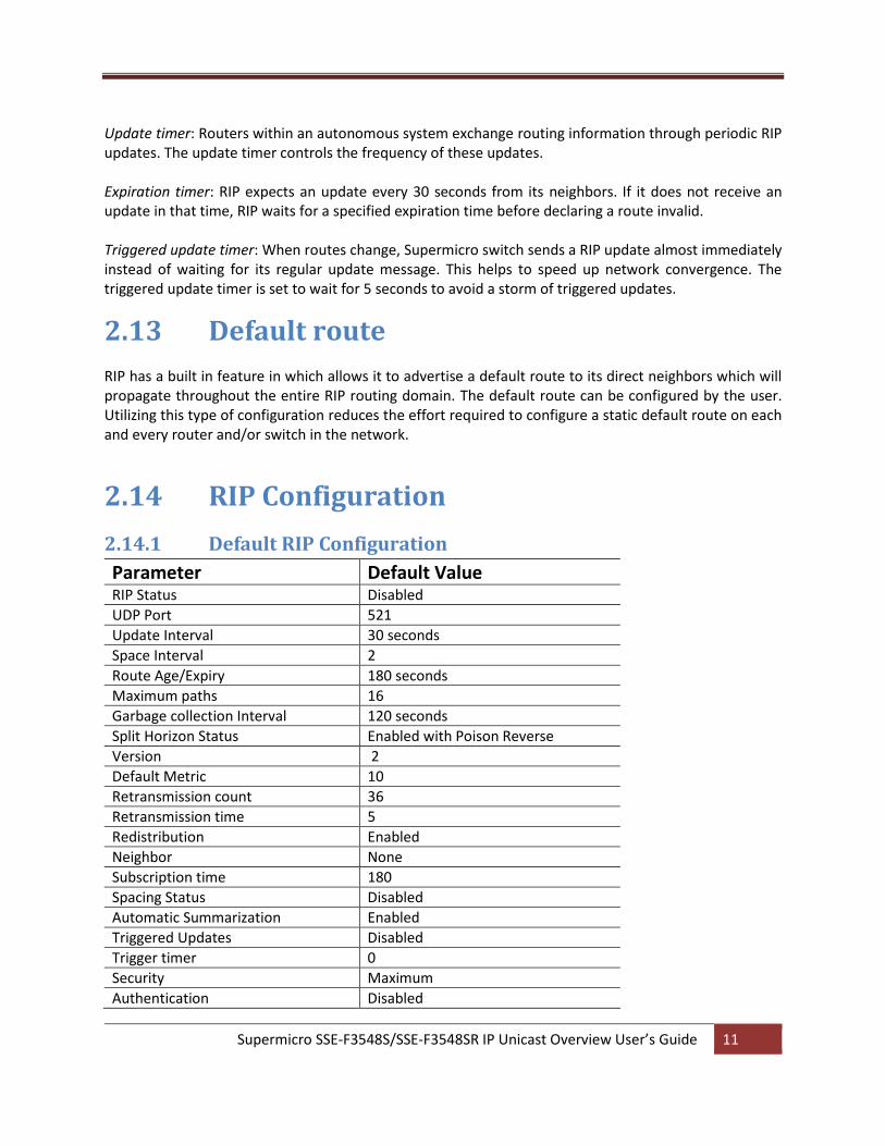
2.14.1 Default RIP Configuration
Parameter Default Value RIP Status Disabled
UDP Port 521
Update Interval 30 seconds
Space Interval 2
Route Age/Expiry 180 seconds
Maximum paths 16
Garbage collection Interval 120 seconds
Split Horizon Status Enabled with Poison Reverse
Version 2
Default Metric 10
Retransmission count 36
Retransmission time 5
Redistribution Enabled
Neighbor None
Subscription time 180
Spacing Status Disabled
Automatic Summarization Enabled
Triggered Updates Disabled
Trigger timer 0
Security Maximum
Authentication Disabled
Supermicro SSE-F3548S/SSE-F3548SR IP Unicast Overview User’s Guide 12
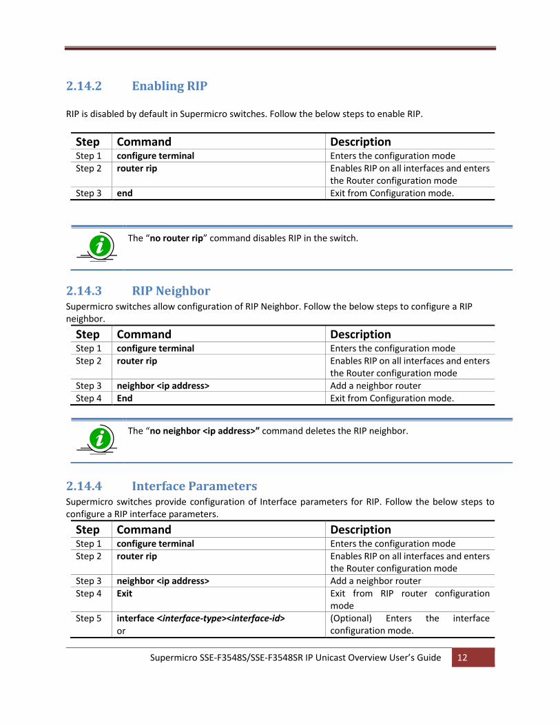
2.14.2 Enabling RIP RIP is disabled by default in Supermicro switches. Follow the below steps to enable RIP.
Step Command Description Step 1 configure terminal Enters the configuration mode Step 2 router rip Enables RIP on all interfaces and enters
the Router configuration mode Step 3 end Exit from Configuration mode.
The “no router rip” command disables RIP in the switch.
2.14.3 RIP Neighbor Supermicro switches allow configuration of RIP Neighbor. Follow the below steps to configure a RIP neighbor.
Step Command Description Step 1 configure terminal Enters the configuration mode Step 2 router rip Enables RIP on all interfaces and enters
the Router configuration mode Step 3 neighbor <ip address> Add a neighbor router Step 4 End Exit from Configuration mode.
The “no neighbor <ip address>” command deletes the RIP neighbor.
2.14.4 Interface Parameters Supermicro switches provide configuration of Interface parameters for RIP. Follow the below steps to configure a RIP interface parameters.
Step Command Description Step 1 configure terminal Enters the configuration mode Step 2 router rip Enables RIP on all interfaces and enters
the Router configuration mode Step 3 neighbor <ip address> Add a neighbor router Step 4 Exit Exit from RIP router configuration
mode Step 5 interface <interface-type><interface-id>
or (Optional) Enters the interface configuration mode.
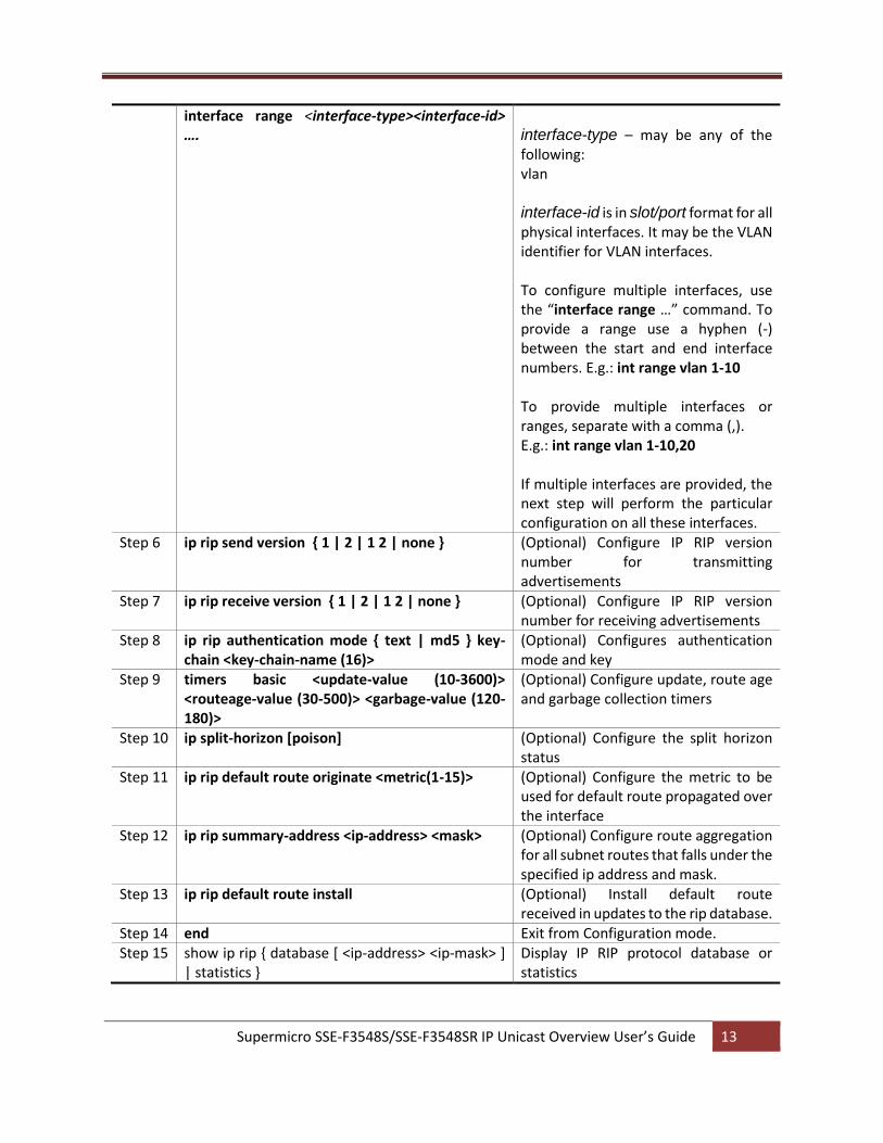
Supermicro SSE-F3548S/SSE-F3548SR IP Unicast Overview User’s Guide 13
interface range <interface-type><interface-id> ….
interface-type – may be any of the following: vlan interface-id is in slot/port format for all physical interfaces. It may be the VLAN identifier for VLAN interfaces. To configure multiple interfaces, use the “interface range …” command. To provide a range use a hyphen (-) between the start and end interface numbers. E.g.: int range vlan 1-10 To provide multiple interfaces or ranges, separate with a comma (,). E.g.: int range vlan 1-10,20 If multiple interfaces are provided, the next step will perform the particular configuration on all these interfaces.
Step 6 ip rip send version { 1 | 2 | 1 2 | none } (Optional) Configure IP RIP version number for transmitting advertisements
Step 7 ip rip receive version { 1 | 2 | 1 2 | none } (Optional) Configure IP RIP version number for receiving advertisements
Step 8 ip rip authentication mode { text | md5 } key-chain <key-chain-name (16)>
(Optional) Configures authentication mode and key
Step 9 timers basic <update-value (10-3600)> <routeage-value (30-500)> <garbage-value (120-180)>
(Optional) Configure update, route age and garbage collection timers
Step 10 ip split-horizon [poison] (Optional) Configure the split horizon status
Step 11 ip rip default route originate <metric(1-15)> (Optional) Configure the metric to be used for default route propagated over the interface
Step 12 ip rip summary-address <ip-address> <mask> (Optional) Configure route aggregation for all subnet routes that falls under the specified ip address and mask.
Step 13 ip rip default route install (Optional) Install default route received in updates to the rip database.
Step 14 end Exit from Configuration mode. Step 15 show ip rip { database [ <ip-address> <ip-mask> ]
| statistics } Display IP RIP protocol database or statistics
Supermicro SSE-F3548S/SSE-F3548SR IP Unicast Overview User’s Guide 14
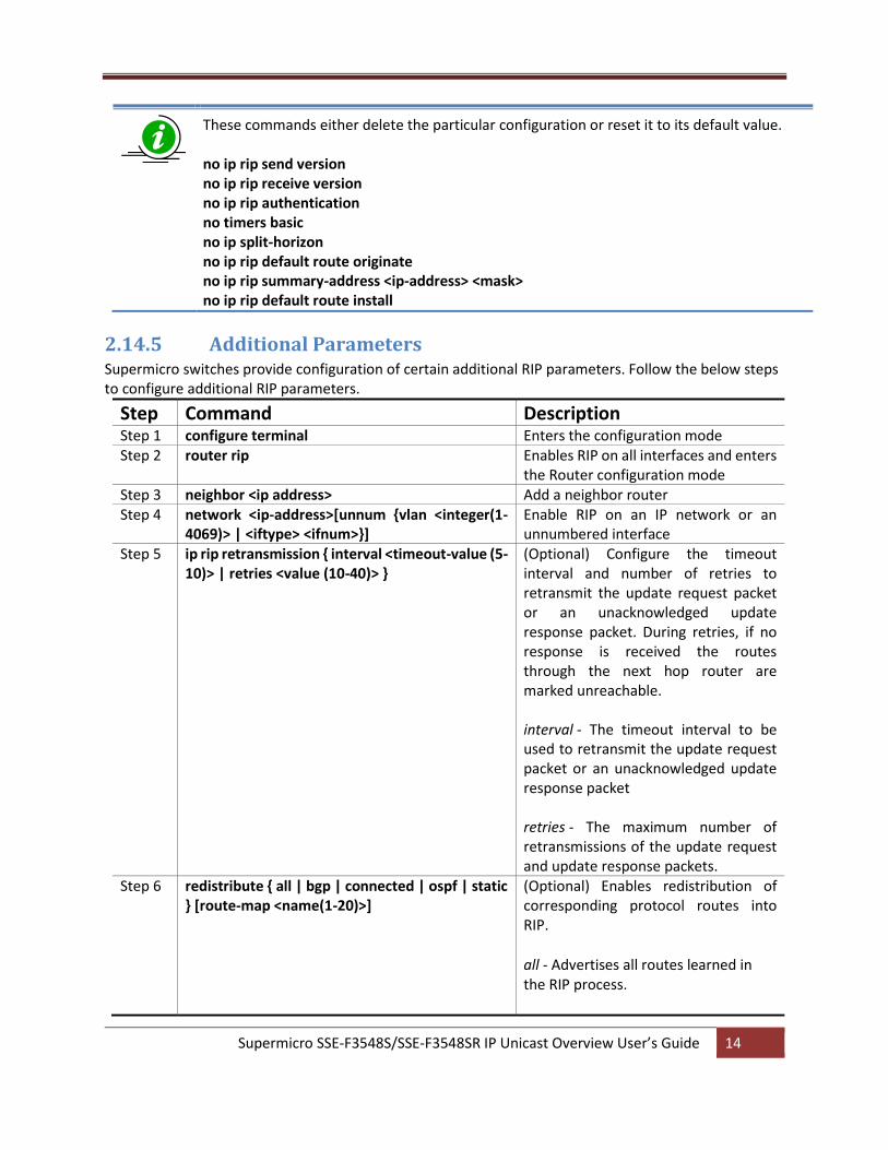
These commands either delete the particular configuration or reset it to its default value. no ip rip send version no ip rip receive version no ip rip authentication no timers basic no ip split-horizon no ip rip default route originate no ip rip summary-address <ip-address> <mask> no ip rip default route install
2.14.5 Additional Parameters Supermicro switches provide configuration of certain additional RIP parameters. Follow the below steps to configure additional RIP parameters.
Step Command Description Step 1 configure terminal Enters the configuration mode Step 2 router rip Enables RIP on all interfaces and enters
the Router configuration mode Step 3 neighbor <ip address> Add a neighbor router Step 4 network <ip-address>[unnum {vlan <integer(1-
4069)> | <iftype> <ifnum>}] Enable RIP on an IP network or an unnumbered interface
Step 5 ip rip retransmission { interval <timeout-value (5-10)> | retries <value (10-40)> }
(Optional) Configure the timeout interval and number of retries to retransmit the update request packet or an unacknowledged update response packet. During retries, if no response is received the routes through the next hop router are marked unreachable. interval - The timeout interval to be used to retransmit the update request packet or an unacknowledged update response packet retries - The maximum number of retransmissions of the update request and update response packets.
Step 6 redistribute { all | bgp | connected | ospf | static } [route-map <name(1-20)>]
(Optional) Enables redistribution of corresponding protocol routes into RIP.
all - Advertises all routes learned in the RIP process.
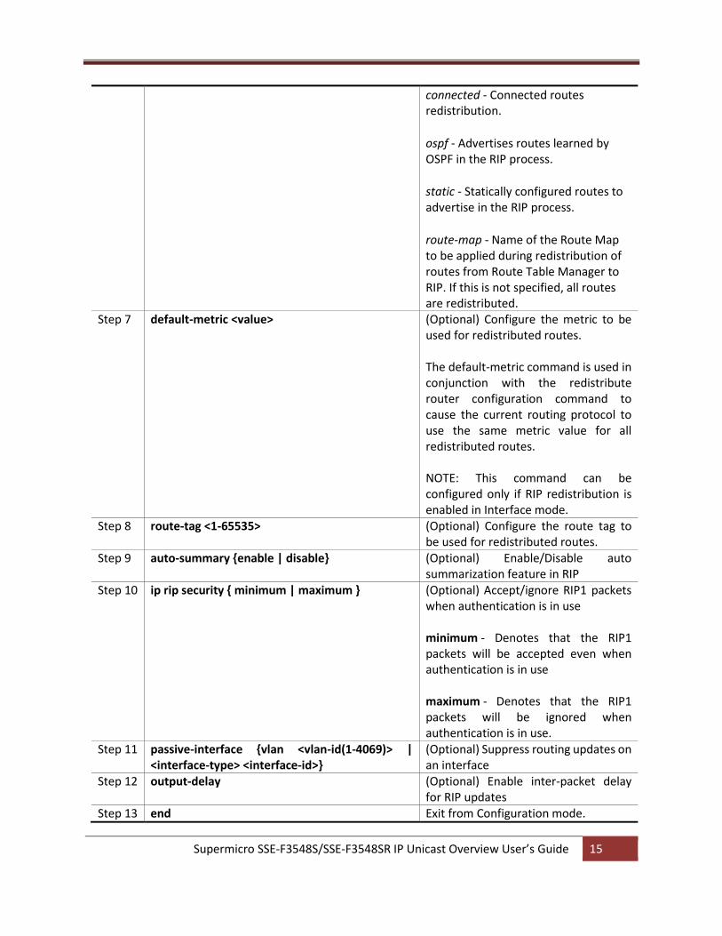
Supermicro SSE-F3548S/SSE-F3548SR IP Unicast Overview User’s Guide 15
connected - Connected routes redistribution.
ospf - Advertises routes learned by OSPF in the RIP process.
static - Statically configured routes to advertise in the RIP process.
route-map - Name of the Route Map to be applied during redistribution of routes from Route Table Manager to RIP. If this is not specified, all routes are redistributed.
Step 7 default-metric <value> (Optional) Configure the metric to be used for redistributed routes. The default-metric command is used in conjunction with the redistribute router configuration command to cause the current routing protocol to use the same metric value for all redistributed routes. NOTE: This command can be configured only if RIP redistribution is enabled in Interface mode.
Step 8 route-tag <1-65535> (Optional) Configure the route tag to be used for redistributed routes.
Step 9 auto-summary {enable | disable} (Optional) Enable/Disable auto summarization feature in RIP
Step 10 ip rip security { minimum | maximum } (Optional) Accept/ignore RIP1 packets when authentication is in use minimum - Denotes that the RIP1 packets will be accepted even when authentication is in use maximum - Denotes that the RIP1 packets will be ignored when authentication is in use.
Step 11 passive-interface {vlan <vlan-id(1-4069)> | <interface-type> <interface-id>}
(Optional) Suppress routing updates on an interface
Step 12 output-delay (Optional) Enable inter-packet delay for RIP updates
Step 13 end Exit from Configuration mode.
Supermicro SSE-F3548S/SSE-F3548SR IP Unicast Overview User’s Guide 16
Step 14 show ip rip { database [ <ip-address> <ip-mask> ] | statistics }
Display IP RIP protocol database or statistics
These commands either delete the particular configuration or reset it to its default value. no network <ip-address> [unnum {vlan <integer(1-4069)> | <iftype> <ifnum>}] no ip rip security no ip rip retransmission { interval | retries } no passive-interface {vlan <vlan-id(1-4069)> | <interface-type> <interface-id>} no output-delay no redistribute { all | bgp | connected | ospf | static } [route-map <name(1-20)>] no default-metric no route-tag
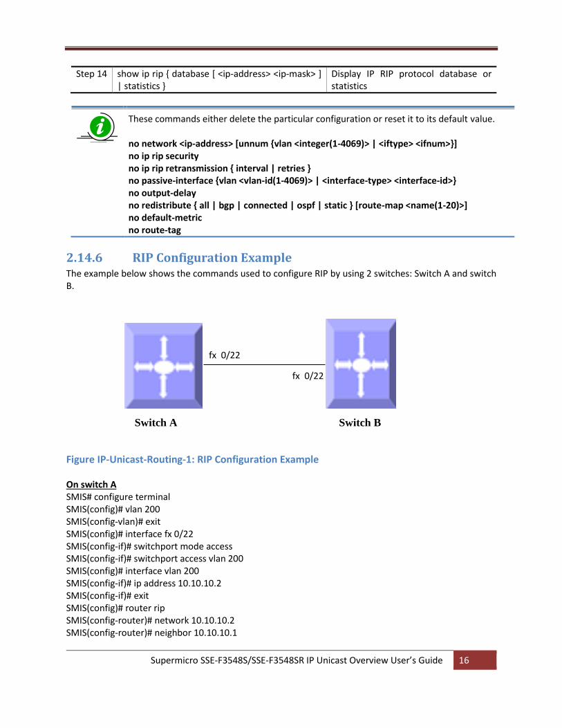
2.14.6 RIP Configuration Example The example below shows the commands used to configure RIP by using 2 switches: Switch A and switch B.
Figure IP-Unicast-Routing-1: RIP Configuration Example On switch A SMIS# configure terminal SMIS(config)# vlan 200 SMIS(config-vlan)# exit SMIS(config)# interface fx 0/22 SMIS(config-if)# switchport mode access SMIS(config-if)# switchport access vlan 200 SMIS(config)# interface vlan 200 SMIS(config-if)# ip address 10.10.10.2 SMIS(config-if)# exit SMIS(config)# router rip SMIS(config-router)# network 10.10.10.2 SMIS(config-router)# neighbor 10.10.10.1
fx 0/22
fx 0/22
Switch A Switch B
Supermicro SSE-F3548S/SSE-F3548SR IP Unicast Overview User’s Guide 17
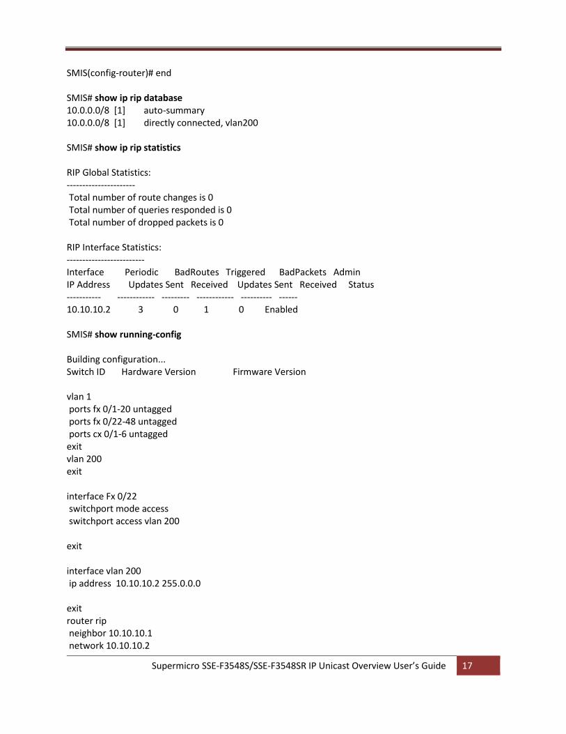
SMIS(config-router)# end SMIS# show ip rip database 10.0.0.0/8 [1] auto-summary 10.0.0.0/8 [1] directly connected, vlan200 SMIS# show ip rip statistics RIP Global Statistics: ---------------------- Total number of route changes is 0 Total number of queries responded is 0 Total number of dropped packets is 0 RIP Interface Statistics: ------------------------- Interface Periodic BadRoutes Triggered BadPackets Admin IP Address Updates Sent Received Updates Sent Received Status ----------- ------------ --------- ------------ ---------- ------ 10.10.10.2 3 0 1 0 Enabled SMIS# show running-config Building configuration... Switch ID Hardware Version Firmware Version vlan 1 ports fx 0/1-20 untagged ports fx 0/22-48 untagged ports cx 0/1-6 untagged exit vlan 200 exit interface Fx 0/22 switchport mode access switchport access vlan 200 exit interface vlan 200 ip address 10.10.10.2 255.0.0.0 exit router rip neighbor 10.10.10.1 network 10.10.10.2
Supermicro SSE-F3548S/SSE-F3548SR IP Unicast Overview User’s Guide 18
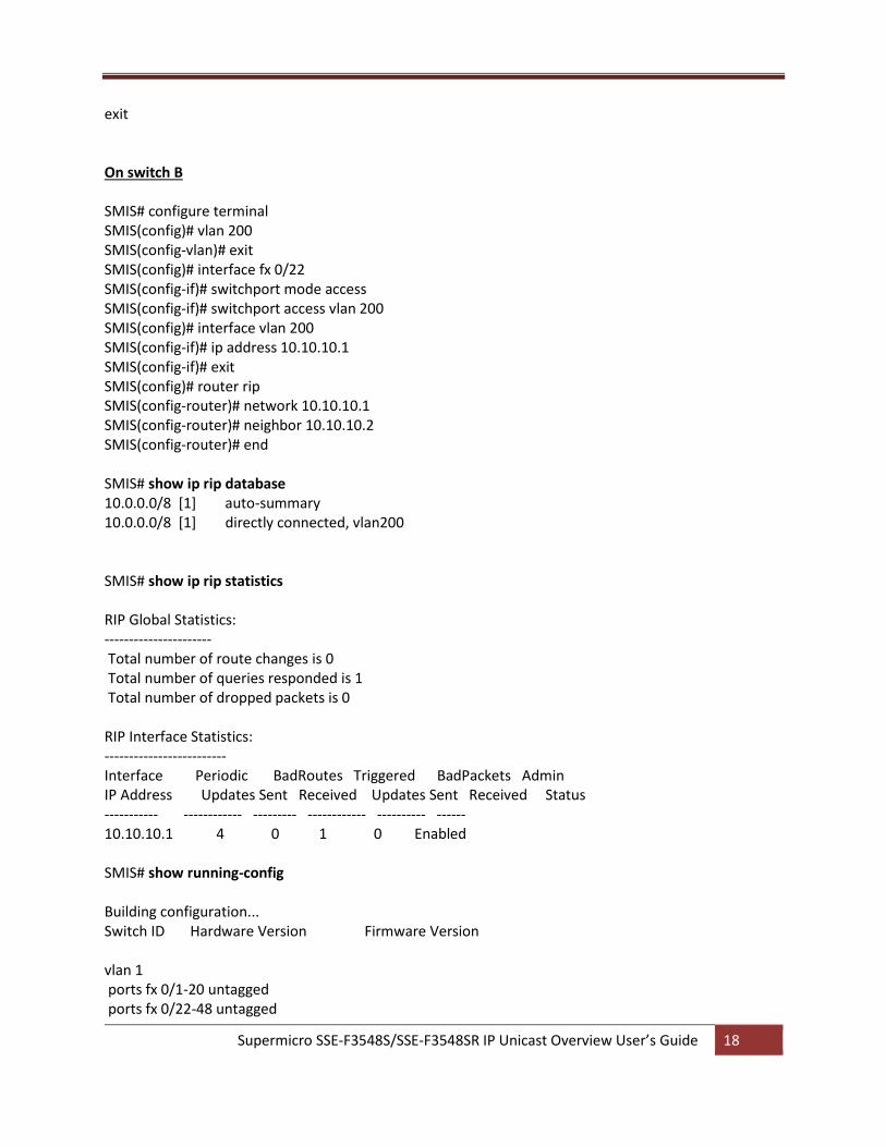
exit On switch B SMIS# configure terminal SMIS(config)# vlan 200 SMIS(config-vlan)# exit SMIS(config)# interface fx 0/22 SMIS(config-if)# switchport mode access SMIS(config-if)# switchport access vlan 200 SMIS(config)# interface vlan 200 SMIS(config-if)# ip address 10.10.10.1 SMIS(config-if)# exit SMIS(config)# router rip SMIS(config-router)# network 10.10.10.1 SMIS(config-router)# neighbor 10.10.10.2 SMIS(config-router)# end SMIS# show ip rip database 10.0.0.0/8 [1] auto-summary 10.0.0.0/8 [1] directly connected, vlan200 SMIS# show ip rip statistics RIP Global Statistics: ---------------------- Total number of route changes is 0 Total number of queries responded is 1 Total number of dropped packets is 0 RIP Interface Statistics: ------------------------- Interface Periodic BadRoutes Triggered BadPackets Admin IP Address Updates Sent Received Updates Sent Received Status ----------- ------------ --------- ------------ ---------- ------ 10.10.10.1 4 0 1 0 Enabled SMIS# show running-config Building configuration... Switch ID Hardware Version Firmware Version vlan 1 ports fx 0/1-20 untagged ports fx 0/22-48 untagged
Supermicro SSE-F3548S/SSE-F3548SR IP Unicast Overview User’s Guide 19
ports cx 0/1-6 untagged exit vlan 200 exit interface Fx 0/22 switchport mode access switchport access vlan 200 exit interface vlan 200 ip address 10.10.10.1 255.0.0.0 exit router rip neighbor 10.10.10.2 network 10.10.10.1 exit interface vlan 200 exit
3 OSPF
OSPF is an Interior Gateway routing protocol that can scale well in large environments. OSPF supports the
following features:
Variable Length Subnet masks (VLSM)
The use of areas to minimize Central Processing Unit (CPU) and memory requirements.
A simple cost metric that can be manipulated to support up to six equal cost paths.
The use of authentication to ensure OSPF updates are secure and the use of multicast updates to
conserve bandwidth.
Faster convergence times ensuring updates and changes are propagated across the network.
No limitation of network diameter or hop count. Limiting factors include only CPU and memory
resources.
The ability to tag OSPF information injected from any autonomous systems.
OSPF enabled switch multicasts Link State Advertisements (LSAs) to inform all other routers in the area of
its neighbors and costs. Based on OSPF LSAs, each router constructs a topology table which contains every
connection link within the network. Then, the Dijkstra algorithm runs over the topology table to find the
Supermicro SSE-F3548S/SSE-F3548SR IP Unicast Overview User’s Guide 20
shortest path to every other router, and hence creates the routing table. This algorithm, which is also
known as the SPF algorithm, runs on every OSPF enabled router on the network, and routers within a
particular area all have the same topology tree of the specific area.
3.1 Neighbor & DR
OSPF routers exchange hellos with neighboring routers and in the process learn their neighbor’s Router ID (RID) and cost, these values are stored to the adjacency table. Supermicro switch establishes OSPF adjacencies between all neighbors on a multi-access network (such as Ethernet). This ensures all routers do not need to maintain full adjacencies with each other. The Designated Router (DR) is selected based on the router priority. In a tie, the router with the highest router ID is selected. Backup DR is a router designed to perform the same functions in case the DR fails.
3.2 LSA
Once a router has exchanged hellos with its neighbors and captured Router IDs and cost information, it begins sending LSAs, or Link State Advertisements. Link state is the information shared between directly connected routers. This information propagates throughout the network unchanged and is also used to create a shortest path first (SPF) tree. The OSPF standard defines a number of LSAs types. Unlike distance vector protocols (for example, RIP), OSPF does not actually send its routing table to other routers. Instead, OSPF sends the LSA database and derives the IP routing table from LSAs.
In order to avoid LSA storm, each LSA has a sequence number which is incremented only if LSA has
changed. Each LSA also has an age value that is set to zero by the originating switch and increased by every
switch during flooding.
The common types of LSA are
Type 1 – Router LSA, containing router ID and link information
Type 2 – Network LSA contains DR and broadcast segment details
Type 3 – Network Summary LSA originated by ABR only and contains metric and subnet information
Type 4 – ASBR Summary LSA originated by ABR only and advertised to ASBR contains router ID, mask and
metric
Type 5 – AS external LSA originated by ASBR contains external route and default route information
Supermicro SSE-F3548S/SSE-F3548SR IP Unicast Overview User’s Guide 21
3.3 Area
An OSPF area is defined as a logical grouping of routers by a network administrator. OSPF routers in any
area contain same topological view, also known as the OSPF database of the network. OSPF is configured
in multiple areas in order to reduce routing table sizes, which in turn reduces the topological database
and switch CPU/memory requirements.
OSPF is not just configured in one large area, so all routers share the same topological database. The use
of multiple areas ensures that the flooding and database management required in large OSPF networks is
reduced within each area so that the process of flooding the full database and maintaining full network
connectivity does not consume a large portion of the CPU processing power and network bandwidth.
Every time a network change occurs, the CPU on a router is interrupted and a new OSPF tree is calculated.
Running the shortest path first (SPF) algorithm itself is not CPU intensive, but sending and flooding the
network with new topological information is extremely CPU intensive.
Areas are identified through a 32-bit Area ID expressed in dotted decimal notation. All OSPF areas must
be connected to the backbone in case of network failure. When an area cannot reside physically or
logically on the backbone, a virtual link is required. There are four types of Areas used in OSPF:
• Backbone Area: Alternate Name for Area 0. This includes all ABRs and internal routers of the
backbone area. The backbone is a hub for inter-area transit traffic and the distribution of routing
information between areas. Inter-area traffic is routed to the backbone, then routed to the
destination area, and finally routed to the destination host within the destination area Routers on
the backbone also advertise the summarized routes within their areas to the other routers on the
backbone. Backbone area helps avoid routing loops as it is the trunk of the network.
• Regular Area: Non-backbone area, with both internal and external routes
• Stub area: An area that contains a single exit point from the area. Areas that reside on the edge
of the network with no exit point except one path can be termed a stub area.
• Not-So-Stubby-Area (NSSA): This area is used to connect to an ISP. All advertised routes can be
flooded through the NSSA but are blocked by the ABR.
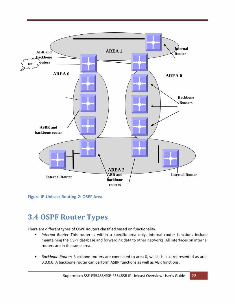
Supermicro SSE-F3548S/SSE-F3548SR IP Unicast Overview User’s Guide 22
Figure IP-Unicast-Routing-2: OSPF Area
3.4 OSPF Router Types
There are different types of OSPF Routers classified based on functionality.
• Internal Router: This router is within a specific area only. Internal router functions include
maintaining the OSPF database and forwarding data to other networks. All interfaces on internal
routers are in the same area.
• Backbone Router: Backbone routers are connected to area 0, which is also represented as area
0.0.0.0. A backbone router can perform ASBR functions as well as ABR functions.
AREA 1
AREA 0
ASBR and
backbone router
ABR and
backbone
routers
Internal
Router
AREA 0
Backbone
Routers
Internal Router Internal Router ABR and
backbone
routers
Int
AREA 2
Supermicro SSE-F3548S/SSE-F3548SR IP Unicast Overview User’s Guide 23
• Area Border Router (ABR): ABRs are responsible for connecting two or more areas. An ABR
contains the full topological database for each area it is connected to and sends this information
to other areas. ABRs contain a separate Link State Database, separating LSA flooding between
areas, optionally summarizing routes, and optionally sourcing default routes.
• Autonomous System Boundary Router (ASBR): Router that has at least one interface in an OSPF
area and at least one interface outside of an OSPF area. Routers that connect to, for example, the
Internet and redistribute external IP routing tables from such protocols as Border Gateway
Protocol (BGP) are termed autonomous system boundary routers (ASBRs).
3.5 Types of routes
OSPF supports two types of routes: Internal routers and External OSPF. External routes are routing entries
in OSPF route tables injected by an external routing protocol, such as BGP. When calculating the cost to a
remote network, internal routes add the total cost to destination; whereas External routes include only the
cost to the external network.
3.6 Default route
When redistribution of routes into an OSPF routing domain is configured, the route becomes an
autonomous system boundary router (ASBR). The ASBR can generate a default route into the OSPF
routing domain by user configuration.
3.7 Metric
The OSPF process assigns cost values to interfaces based on the inverse of the bandwidth parameter
assigned to the interface with the bandwidth command. For calculating the SPF to a given destination, the
router takes into consideration the costs of the links along various paths. The path with the lower cost is
selected as the shortest path. The SPF algorithm only runs within a single area, so routers only compute
paths within their own area. Inter-area routes are passed using border routers.
3.8 Router Id
The source of Link-state Advertisements in a given area is identified by the Router ID. This ID has the form of an IP address and can be automatically or manually defined.
Supermicro SSE-F3548S/SSE-F3548SR IP Unicast Overview User’s Guide 24
3.9 Priority
In multi-access networks the router with the highest priority value is chosen as the DR which acts as the central point of LSAs exchange. Supermicro switches provide OSPF DR priority configuration.
3.10 Route Summarization
Route summarization is the consolidation of advertised addresses into a single summary route to be advertised by other areas. Summarization occurs using the LSA type 4 packet or by the ASBR. OSPF can be configured in two ways to summarize networks:
Inter-area summarization creating type 3 or 4 LSAs
External summarization with type 5 LSAs
3.11 Authentication
OSPF does not authenticate its protocol’s messages or route updates. OSPF does, however, support two
message authentication options:
Simple Authentication- using plaintext keys
MD5 Authentication - Matching authentication methods and keys must be configured on each
interface on a segment. Theoretically, different passwords could be applied to different router
interfaces – the routers on the other ends of those links would just be required to have matching
information.
3.12 Timers
Supermicro switches provide configuration of the delay time between when OSPF receives a topology change and when it starts the shortest path first (SPF) calculation and the hold time between two SPF calculations.
3.13 Virtual Link
In OSPF, all areas must be connected to a backbone area. A virtual link can be configured in case of a backbone-continuity break by configuring two Area Border Routers as endpoints of a virtual link. Configuration information includes the identity of the other virtual endpoint (the other ABR) and the non-backbone link that the two routers have in common (the transit area). Virtual links cannot be configured through a stub area.
Supermicro SSE-F3548S/SSE-F3548SR IP Unicast Overview User’s Guide 25
3.14 Passive Interface
The passive-interface interface command disables OSPF hellos from being sent out, thus disabling the
interface from forming adjacencies out that interface.
3.15 Demand Circuit
A demand circuit is a point-to-point connection between two neighboring interfaces configured for OSPF. Demand circuits increase the efficiency of OSPF on the configured interfaces by stopping the periodic transmission of OSPF packets, like Hello and LSA. OSPF can establish a demand link to form an adjacency and perform initial database synchronization; the adjacency remains active even after Layer 2 of the demand circuit goes down.
3.16 Network Type
Internet network types are dependent on the layer 2 technology used such as Ethernet, point-to-point T1
circuit, and frame relay. The various OSPF network types and their compatibility with one another are
specified below.
Non-Broadcast: This is the default for OSPF enabled frame relay physical interfaces. Non-Broadcast
networks require static neighbor configuration and OSPF hellos are sent via unicast. The Non-Broadcast
network type has a 30 second hello and 120 second dead timer. An OSPF Non-Broadcast network type
requires the use of a DR/BDR.
Broadcast: This is the default for an OSPF enabled ethernet interface. The Broadcast network type
requires link support Layer 2 Broadcast capabilities. The Broadcast network type has a 10 second hello
and 40 second dead timer. An OSPF Broadcast network type requires the use of a DR/BDR.
Point-to-Point: A Point-to-Point OSPF network type does not maintain a DR/BDR relationship. The Point-
to-Point network type has a 10 second hello and 40 second dead timer. Point-to-Point network types are
intended to be used between 2 directly connected routers.
Point-to-Multipoint: This is viewed as a collection of point-to-point links. Point-to-Multipoint networks do
not maintain a DR/BDR and advertise a hot route for all the frame-relay endpoints. The Point-to-Multipoint
network type has a 30 second hello and 120 second dead timer.
Supermicro SSE-F3548S/SSE-F3548SR IP Unicast Overview User’s Guide 26
3.17 OSPF Configuration
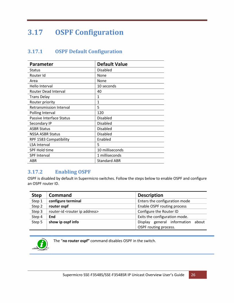
3.17.1 OSPF Default Configuration
Parameter Default Value Status Disabled
Router Id None
Area None
Hello Interval 10 seconds
Router Dead Interval 40
Trans Delay 1
Router priority 1
Retransmission Interval 5
Polling Interval 120
Passive Interface Status Disabled
Secondary IP Disabled
ASBR Status Disabled
NSSA ASBR Status Disabled
RPF 1583 Compatibility Enabled
LSA Interval 5
SPF Hold time 10 milliseconds
SPF Interval 1 milliseconds
ABR Standard ABR
3.17.2 Enabling OSPF OSPF is disabled by default in Supermicro switches. Follow the steps below to enable OSPF and configure an OSPF router ID.
Step Command Description Step 1 configure terminal Enters the configuration mode Step 2 router ospf Enable OSPF routing process Step 3 router-id <router ip address> Configure the Router ID Step 4 End Exits the configuration mode. Step 5 show ip ospf info
Display general information about OSPF routing process.
The “no router ospf” command disables OSPF in the switch.
Supermicro SSE-F3548S/SSE-F3548SR IP Unicast Overview User’s Guide 27
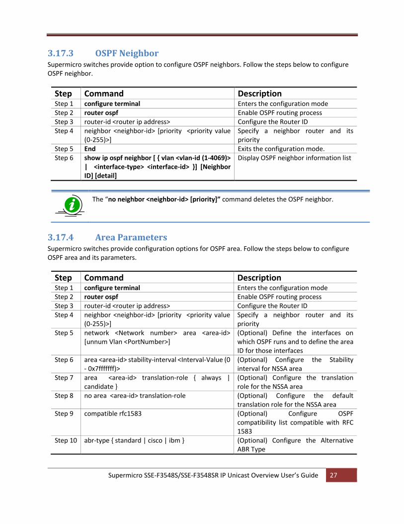
3.17.3 OSPF Neighbor Supermicro switches provide option to configure OSPF neighbors. Follow the steps below to configure OSPF neighbor.
Step Command Description Step 1 configure terminal Enters the configuration mode Step 2 router ospf Enable OSPF routing process Step 3 router-id <router ip address> Configure the Router ID Step 4 neighbor <neighbor-id> [priority <priority value
(0-255)>] Specify a neighbor router and its priority
Step 5 End Exits the configuration mode. Step 6 show ip ospf neighbor [ { vlan <vlan-id (1-4069)>
| <interface-type> <interface-id> }] [Neighbor ID] [detail]
Display OSPF neighbor information list
The “no neighbor <neighbor-id> [priority]” command deletes the OSPF neighbor.
3.17.4 Area Parameters Supermicro switches provide configuration options for OSPF area. Follow the steps below to configure OSPF area and its parameters.
Step Command Description Step 1 configure terminal Enters the configuration mode Step 2 router ospf Enable OSPF routing process Step 3 router-id <router ip address> Configure the Router ID Step 4 neighbor <neighbor-id> [priority <priority value
(0-255)>] Specify a neighbor router and its priority
Step 5 network <Network number> area <area-id> [unnum Vlan <PortNumber>]
(Optional) Define the interfaces on which OSPF runs and to define the area ID for those interfaces
Step 6 area <area-id> stability-interval <Interval-Value (0 - 0x7fffffff)>
(Optional) Configure the Stability interval for NSSA area
Step 7 area <area-id> translation-role { always | candidate }
(Optional) Configure the translation role for the NSSA area
Step 8 no area <area-id> translation-role (Optional) Configure the default translation role for the NSSA area
Step 9 compatible rfc1583 (Optional) Configure OSPF compatibility list compatible with RFC 1583
Step 10 abr-type { standard | cisco | ibm } (Optional) Configure the Alternative ABR Type
Supermicro SSE-F3548S/SSE-F3548SR IP Unicast Overview User’s Guide 28
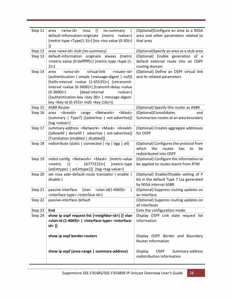
Step 11 area <area-id> nssa [{ no-summary | default-information-originate [metric <value>] [metric-type <Type(1-3)>] [tos <tos value (0-30)>] }]
(Optional)Configure an area as a NSSA area and other parameters related to that area
Step 12 area <area-id> stub [no-summary] (Optional)Specify an area as a stub area Step 13 default-information originate always [metric
<metric-value (0-0xffffff)>] [metric-type <type (1-2)>]
(Optional) Enable generation of a default external route into an OSPF routing domain
Step 14 area <area-id> virtual-link <router-id> [authentication { simple |message-digest | null}] [hello-interval <value (1-65535)>] [retransmit-interval <value (0-3600)>] [transmit-delay <value (0-3600)>] [dead-interval <value>] [{authentication-key <key (8)> | message-digest-key <Key-id (0-255)> md5 <key (16)>}]
(Optional) Define an OSPF virtual link and its related parameters
Step 15 ASBR Router (Optional) Specify this router as ASBR Step 16 area <AreaId> range <Network> <Mask>
{summary | Type7} [{advertise | not-advertise}] [tag <value>]
(Optional)Consolidates and Summarizes routes at an area boundary
Step 17 summary-address <Network> <Mask> <AreaId> [{allowAll | denyAll | advertise | not-advertise}] [Translation {enabled | disabled}]
(Optional) Creates aggregate addresses for OSPF
Step 18 redistribute {static | connected | rip | bgp | all} (Optional) Configures the protocol from which the routes has to be redistributed into OSPF
Step 19 redist-config <Network> <Mask> [metric-value <metric (1 - 16777215)>] [metric-type {asExttype1 | asExttype2}] [tag <tag-value>}
(Optional) Configure the information to be applied to routes learnt from RTM
Step 20 set nssa asbr-default-route translator { enable | disable }
(Optional) Enable/Disable setting of P bit in the default Type 7 Lsa generated by NSSA internal ASBR
Step 21 passive-interface {vlan <vlan-id(1-4069)> | <interface-type> <interface-id>}
(Optional) Suppress routing updates on an interface
Step 22 passive-interface default (Optional) Suppress routing updates on all interfaces
Step 23 End Exits the configuration mode. Step 24 show ip ospf request-list [<neighbor-id>] [{ vlan
<vlan-id (1-4069)> | <interface-type> <interface-id> }] show ip ospf border-routers show ip ospf {area-range | summary-address}
Display OSPF Link state request list information Display OSPF Border and Boundary Router Information Display OSPF Summary-address redistribution Information
Supermicro SSE-F3548S/SSE-F3548SR IP Unicast Overview User’s Guide 29
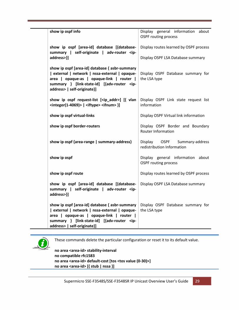
show ip ospf info show ip ospf [area-id] database [{database-summary | self-originate | adv-router <ip-address>}] show ip ospf [area-id] database { asbr-summary | external | network | nssa-external | opaque-area | opaque-as | opaque-link | router | summary } [link-state-id] [{adv-router <ip-address> | self-originate}] show ip ospf request-list [<ip_addr>] [{ vlan <integer(1-4069)> | <iftype> <ifnum> }] show ip ospf virtual-links show ip ospf border-routers show ip ospf {area-range | summary-address} show ip ospf show ip ospf route show ip ospf [area-id] database [{database-summary | self-originate | adv-router <ip-address>}] show ip ospf [area-id] database { asbr-summary | external | network | nssa-external | opaque-area | opaque-as | opaque-link | router | summary } [link-state-id] [{adv-router <ip-address> | self-originate}]
Display general information about OSPF routing process Display routes learned by OSPF process Display OSPF LSA Database summary Display OSPF Database summary for the LSA type Display OSPF Link state request list information Display OSPF Virtual link information Display OSPF Border and Boundary Router Information Display OSPF Summary-address redistribution Information Display general information about OSPF routing process Display routes learned by OSPF process Display OSPF LSA Database summary Display OSPF Database summary for the LSA type
These commands delete the particular configuration or reset it to its default value. no area <area-id> stability-interval no compatible rfc1583 no area <area-id> default-cost [tos <tos value (0-30)>] no area <area-id> [{ stub | nssa }]
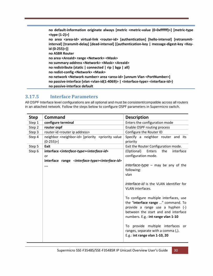
Supermicro SSE-F3548S/SSE-F3548SR IP Unicast Overview User’s Guide 30
no default-information originate always [metric <metric-value (0-0xffffff)>] [metric-type <type (1-2)>] no area <area-id> virtual-link <router-id> [authentication] [hello-interval] [retransmit-interval] [transmit-delay] [dead-interval] [{authentication-key | message-digest-key <Key-id (0-255)>}] no ASBR Router no area <AreaId> range <Network> <Mask> no summary-address <Network> <Mask> <AreaId> no redistribute {static | connected | rip | bgp | all} no redist-config <Network> <Mask> no network <Network number> area <area-id> [unnum Vlan <PortNumber>] no passive-interface {vlan <vlan-id(1-4069)> | <interface-type> <interface-id>} no passive-interface default
3.17.5 Interface Parameters All OSPF Interface level configurations are all optional and must be consistent/compatible across all routers
in an attached network. Follow the steps below to configure OSPF parameters in Supermicro switch.
Step Command Description Step 1 configure terminal Enters the configuration mode Step 2 router ospf Enable OSPF routing process Step 3 router-id <router ip address> Configure the Router ID Step 4 neighbor <neighbor-id> [priority <priority value
(0-255)>] Specify a neighbor router and its priority
Step 5 Exit Exit the Router Configuration mode. Step 6 interface <interface-type><interface-id>
or interface range <interface-type><interface-id> ….
(Optional) Enters the interface configuration mode. interface-type – may be any of the following: vlan interface-id is the VLAN identifier for VLAN interfaces. To configure multiple interfaces, use the “interface range …” command. To provide a range use a hyphen (-) between the start and end interface numbers. E.g.: int range vlan 1-10 To provide multiple interfaces or ranges, separate with a comma (,). E.g.: int range vlan 1-10, 20
Supermicro SSE-F3548S/SSE-F3548SR IP Unicast Overview User’s Guide 31
If multiple interfaces are provided, the next step will perform the particular configuration on all these interfaces.
Step 7 ip ospf demand-circuit Configure OSPF to treat the interface as an OSPF demand circuit
Step 8 ip ospf retransmit-interval <seconds (0 - 3600)> Specify the time between link-state advertisement (LSA) retransmissions for adjacencies belonging to the interface
Step 9 ip ospf transmit-delay <seconds (0 - 3600)> (Optional) Configure the estimated time it takes to transmit a link state update packet on the interface
Step 10 ip ospf priority <value (0 - 255)> (Optional) Configure the router priority Step 11 ip ospf hello-interval <seconds (1 - 65535)> (Optional) Specify the interval between
hello packets sent on the interface Step 12 ip ospf dead-interval <seconds (0-0x7fffffff)> (Optional) Configure the interval at
which hello packets must not be seen before neighbors declare the router down
Step 13 ip ospf cost <cost (1-65535)> [tos <tos value (0-30)>]
(Optional) Explicitly specify the cost of sending a packet on an interface
Type of Service (TOS) is defined as a mapping to the IP Type of Service Flags as defined in the IP Forwarding Table MIB. The condition to select next-hop for a destination from a multipath route (set of next hops for a given destination) is referred to as 'policy', which is specified by the TOS Field. However, TOS field is no longer in use.
Step 14 ip ospf network {broadcast | non-broadcast | point-to-multipoint | point-to-point}
(Optional) Configure the OSPF network type to a type other than the default for a given media
Step 15 ip ospf authentication-key <password (8)> (Optional) Specify a password to be used by neighboring routers that are using the OSPF simple password authentication
Step 16 ip ospf authentication [{message-digest | null}] (Optional) Specify the authentication type for an interface
Step 17 ip ospf message-digest-key <Key-ID (0-255)> md5 <md5-Key (16)>
(Optional) Enable OSPF MD5 authentication
Step 18 End Exits the configuration mode. Step 19 show ip ospf interface [ { vlan <vlan-id (1-4069)>
| <interface-type> <interface-id> }] Display OSPF interface information
Supermicro SSE-F3548S/SSE-F3548SR IP Unicast Overview User’s Guide 32
show ip ospf retransmission-list [<neighbor-id>] [{ vlan <vlan-id (1-4069)> | <interface-type> <interface-id> }] show ip ospf info
Display OSPF Link state retransmission list information Display general information about OSPF routing process
These commands delete the particular configuration or reset it to its default value. no ip ospf demand-circuit no ip ospf retransmit-interval no ip ospf transmit-delay no ip ospf priority no ip ospf hello-interval no ip ospf dead-interval no ip ospf cost [tos <tos value (0-30)>] no ip ospf network no ip ospf authentication-key no ip ospf authentication no ip ospf message-digest-key <Key-ID (0-255)>
3.17.6 OSPF Configuration Example The example below shows the commands used to configure OSPF by connecting 2 switches: Switch A and Switch B.
Figure IP-Unicast-Routing-3: OSPF Configuration Example .On Switch A
fx 0/21
fx 0/22
Switch B SwitchA
Supermicro SSE-F3548S/SSE-F3548SR IP Unicast Overview User’s Guide 33
SMIS# configure terminal SMIS(config)# vlan 10 SMIS(config-vlan)# ports fx 0/21 untagged SMIS(config-vlan)# exit SMIS(config)# interface fx 0/21 SMIS(config-if)# switchport pvid 10 SMIS(config-if)# exit SMIS(config)# interface vlan 10 SMIS(config-if)# ip address 10.10.10.1 SMIS(config-if)# exit SMIS(config)# router ospf SMIS(config-router)# router-id 10.10.10.1 SMIS(config-router)# network 10.10.10.1 area 0.0.0.0 SMIS(config-router)# end SMIS# show ip ospf neighbor Vrf default Neighbor-ID Pri State DeadTime Address Interface ----------- --- ----- -------- ------- --------- 10.10.10.2 100 FULL/DR_OTHER 30 10.10.10.2 vlan10 SMIS# show ip ospf info OSPF Router with ID (10.10.10.1) (Vrf default) Supports only single TOS(TOS0) route ABR Type supported is Standard ABR Number of Areas in this router is 1 Area is 0.0.0.0 Number of interfaces in this area is 1 SPF algorithm executed 15 times SMIS# show ip ospf route Vrf default OSPF Routing Table Dest/Mask TOS NextHop/Interface Cost Rt.Type Area --------- --- -------/--------- ---- ------- ---- 10.0.0.0/255.0.0.0 0 0.0.0.0/vlan10 100 IntraArea 0.0.0.0 SMIS# show ip ospf interface vlan10 is line protocol is up
Supermicro SSE-F3548S/SSE-F3548SR IP Unicast Overview User’s Guide 34
Internet Address 10.10.10.1, Mask 255.0.0.0, Area 0.0.0.0 AS 1, Router ID 10.10.10.1, Network Type BROADCAST, Cost 100 Transmit Delay is 500 sec, State 4, Priority 200 Designated RouterId 10.10.10.1, Interface address 10.10.10.1 Backup Designated RouterId 10.10.10.2, Interface address 10.10.10.2 Timer intervals configured, Hello 10, Dead 40, Wait 40, Retransmit 500 Hello due in 4 sec Neighbor Count is 1, Adjacent neighbor count is 1 Adjacent with the neighbor 10.10.10.2 Connected to VRF default SMIS# show running-config Building configuration... Switch ID Hardware Version Firmware Version vlan 1 ports fx 0/1-48 untagged ports cx 0/1-6 untagged exit vlan 10 ports fx 0/21 untagged exit interface Fx 0/21 switchport pvid 10 exit interface vlan 10 ip address 10.10.10.1 255.0.0.0 exit router ospf router-id 10.10.10.1 network 10.10.10.1 area 0.0.0.0 exit On Switch B SMIS# configure terminal SMIS(config)# vlan 10 SMIS(config-vlan)# ports fx 0/22 untagged SMIS(config-vlan)# exit SMIS(config)# interface fx 0/22 SMIS(config-if)# switchport pvid 10 SMIS(config-if)# exit SMIS(config)# interface vlan 10
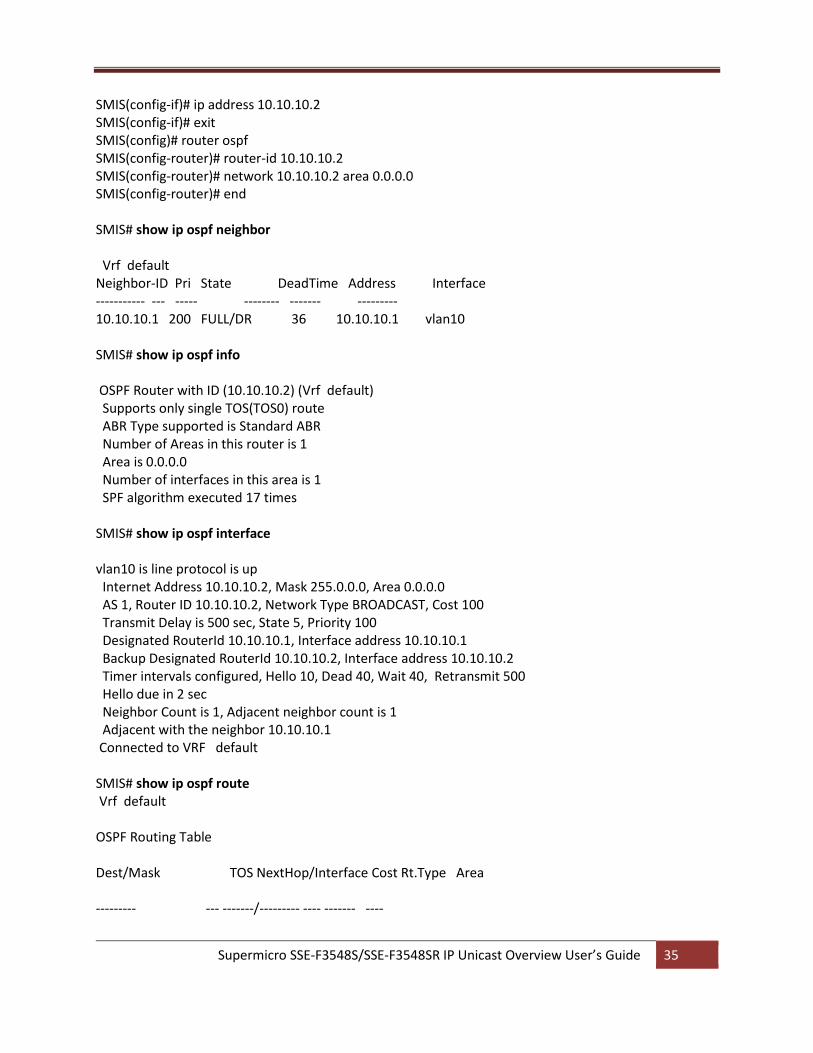
Supermicro SSE-F3548S/SSE-F3548SR IP Unicast Overview User’s Guide 35
SMIS(config-if)# ip address 10.10.10.2 SMIS(config-if)# exit SMIS(config)# router ospf SMIS(config-router)# router-id 10.10.10.2 SMIS(config-router)# network 10.10.10.2 area 0.0.0.0 SMIS(config-router)# end SMIS# show ip ospf neighbor Vrf default Neighbor-ID Pri State DeadTime Address Interface ----------- --- ----- -------- ------- --------- 10.10.10.1 200 FULL/DR 36 10.10.10.1 vlan10 SMIS# show ip ospf info OSPF Router with ID (10.10.10.2) (Vrf default) Supports only single TOS(TOS0) route ABR Type supported is Standard ABR Number of Areas in this router is 1 Area is 0.0.0.0 Number of interfaces in this area is 1 SPF algorithm executed 17 times SMIS# show ip ospf interface vlan10 is line protocol is up Internet Address 10.10.10.2, Mask 255.0.0.0, Area 0.0.0.0 AS 1, Router ID 10.10.10.2, Network Type BROADCAST, Cost 100 Transmit Delay is 500 sec, State 5, Priority 100 Designated RouterId 10.10.10.1, Interface address 10.10.10.1 Backup Designated RouterId 10.10.10.2, Interface address 10.10.10.2 Timer intervals configured, Hello 10, Dead 40, Wait 40, Retransmit 500 Hello due in 2 sec Neighbor Count is 1, Adjacent neighbor count is 1 Adjacent with the neighbor 10.10.10.1 Connected to VRF default SMIS# show ip ospf route Vrf default OSPF Routing Table Dest/Mask TOS NextHop/Interface Cost Rt.Type Area --------- --- -------/--------- ---- ------- ----
Supermicro SSE-F3548S/SSE-F3548SR IP Unicast Overview User’s Guide 36
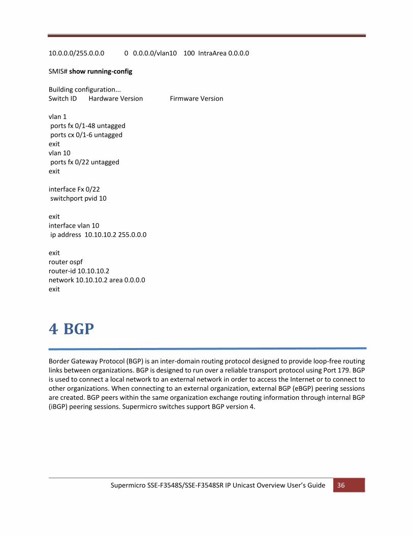
10.0.0.0/255.0.0.0 0 0.0.0.0/vlan10 100 IntraArea 0.0.0.0 SMIS# show running-config Building configuration... Switch ID Hardware Version Firmware Version vlan 1 ports fx 0/1-48 untagged ports cx 0/1-6 untagged exit vlan 10 ports fx 0/22 untagged exit interface Fx 0/22 switchport pvid 10 exit interface vlan 10 ip address 10.10.10.2 255.0.0.0 exit router ospf router-id 10.10.10.2 network 10.10.10.2 area 0.0.0.0 exit
4 BGP Border Gateway Protocol (BGP) is an inter-domain routing protocol designed to provide loop-free routing links between organizations. BGP is designed to run over a reliable transport protocol using Port 179. BGP is used to connect a local network to an external network in order to access the Internet or to connect to other organizations. When connecting to an external organization, external BGP (eBGP) peering sessions are created. BGP peers within the same organization exchange routing information through internal BGP (iBGP) peering sessions. Supermicro switches support BGP version 4.
Supermicro SSE-F3548S/SSE-F3548SR IP Unicast Overview User’s Guide 37
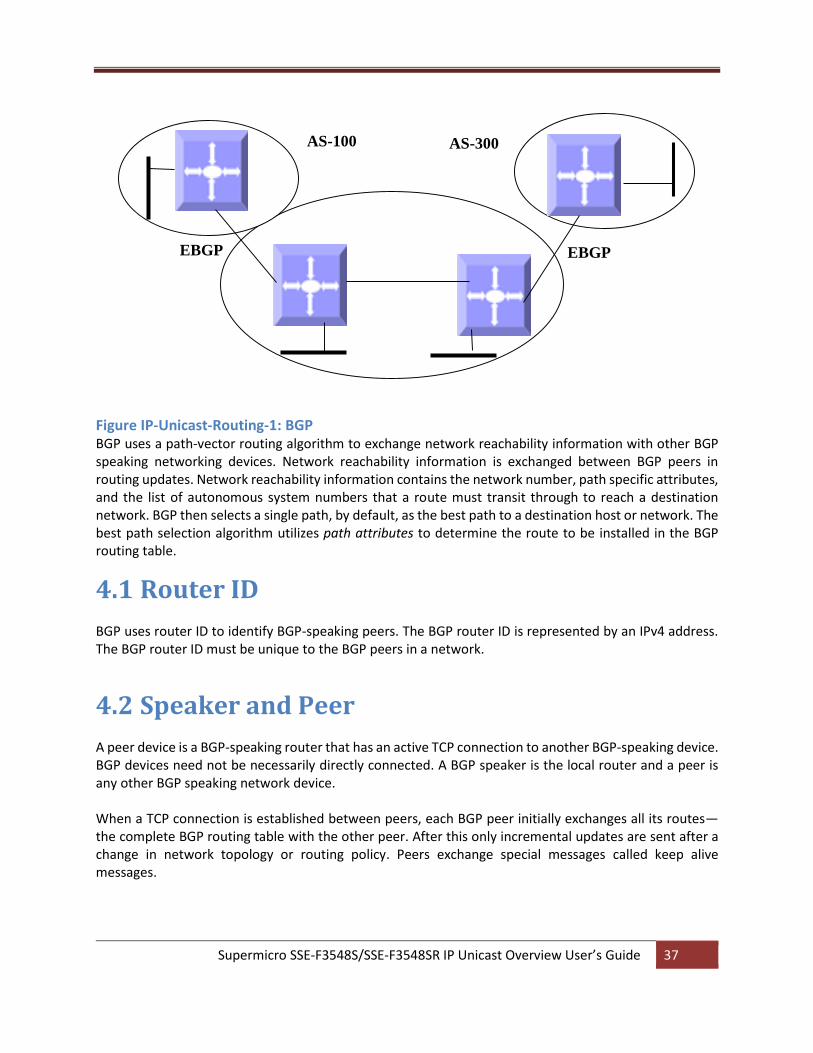
Figure IP-Unicast-Routing-1: BGP BGP uses a path-vector routing algorithm to exchange network reachability information with other BGP speaking networking devices. Network reachability information is exchanged between BGP peers in routing updates. Network reachability information contains the network number, path specific attributes, and the list of autonomous system numbers that a route must transit through to reach a destination network. BGP then selects a single path, by default, as the best path to a destination host or network. The best path selection algorithm utilizes path attributes to determine the route to be installed in the BGP routing table.
4.1 Router ID
BGP uses router ID to identify BGP-speaking peers. The BGP router ID is represented by an IPv4 address. The BGP router ID must be unique to the BGP peers in a network.
4.2 Speaker and Peer
A peer device is a BGP-speaking router that has an active TCP connection to another BGP-speaking device. BGP devices need not be necessarily directly connected. A BGP speaker is the local router and a peer is any other BGP speaking network device. When a TCP connection is established between peers, each BGP peer initially exchanges all its routes—the complete BGP routing table with the other peer. After this only incremental updates are sent after a change in network topology or routing policy. Peers exchange special messages called keep alive messages.
AS-200
IBGP
EBGP EBGP
AS-300 AS-100
Supermicro SSE-F3548S/SSE-F3548SR IP Unicast Overview User’s Guide 38
4.3 Autonomous System (AS)
An autonomous system is a network controlled by a single technical administration entity. In BGP autonomous systems are used in individual routing domains with local routing policies. Each routing domain can support multiple routing protocols. However, each routing protocol is administrated separately. Other routing protocols can dynamically exchange routing information with BGP through redistribution.
4.4 Aggregate Addresses
Classless inter-domain routing (CIDR) enables creation of aggregate routes (or supernets) to minimize the size of routing tables. Aggregate routes can be configured in BGP either by redistributing an aggregate route into BGP or by creating an aggregate entry in the BGP routing table.
4.5 Route Reflection
Typical BGP requires all IBGP speakers to be fully meshed i.e. when a router receives a route from an external neighbor, it must advertise it to all internal neighbors. To prevent a routing information loop, all IBPG speakers must be connected and the internal neighbors do not share routes among themselves. With route reflectors, all IBGP speakers need not be fully meshed because another method is used to pass learned routes to neighbors. When an internal BGP peer is configured to be a route reflector, it is responsible for passing IBGP learned routes to a set of IBGP neighbors. The internal peers of the route reflector are divided into two groups: client peers and non-client peers (all the other routers in the autonomous system). A route reflector reflects routes between these two groups. The route reflector and its client peers form a cluster. The non-client peers must be fully meshed with each other, but the client peers need not be fully meshed. The clients in the cluster do not communicate with IBGP speakers outside their cluster. When the route reflector receives an advertised route, it takes one of these actions, depending on the neighbor: • A route from an external BGP speaker is advertised to all clients and non-client peers. • A route from a non-client peer is advertised to all clients. • A route from a client is advertised to all clients and non-client peers. Hence, the clients need not be fully meshed. To increase redundancy and to avoid a single point of failure, a cluster might have more than one route reflector. In this case, all route reflectors in the cluster must be configured with the same cluster ID so that a route reflector can recognize updates from route reflectors in the same cluster. All the route reflectors serving a cluster should be fully meshed and should have identical sets of client and non-client peers.
Supermicro SSE-F3548S/SSE-F3548SR IP Unicast Overview User’s Guide 39
4.6 Confederation
Another way to reduce the IBGP mesh is to divide an autonomous system into multiple sub-autonomous systems and group them into a single confederation to make it appear as a single autonomous system. Each autonomous system is fully meshed within itself and has a few connections to other autonomous systems in the same confederation. Even though the peers in different autonomous systems have EBGP sessions, they exchange routing information as if they were IBGP peers. Specifically, the next hop, MED and local preference information is preserved. A confederation identifier must be configured to act as the autonomous system number for the group of autonomous systems.
4.7 Attributes
BGP has a number of complex attributes used to determine a path to a remote network. These attributes
allow greater flexibility and enable a complex routing decision to ensure that the path to a remote network
is the best possible path. BGP always propagates the best path to any peers. BGP attributes are carried
in update packets.
4.7.1 Multi-Exit Discriminator (MED) Attribute
The multi-exit discriminator (MED) or metric attribute is used as a suggestion to an external AS regarding
the preferred route into the AS that is advertising the metric. A lower MED is always preferred.
4.7.2 Local Preference Attribute
If there are multiple exit points from the AS, the local preference attribute is used to select the exit point
for a specific route. A higher local preference is always preferred.
4.7.3 Next-Hop Attribute
The EBGP next-hop attribute is the IP address that is used to reach the advertising router. For EBGP peers,
the next-hop address is the IP address of the connection between the peers. For IBGP, the EBGP next-hop
address is carried into the local AS
4.7.4 Community Attribute
Communities allow routes to be tagged for use with a group of routers sharing the same characteristics.
The community attribute provides a way of grouping destinations, called communities, to which routing
decisions (such as acceptance, preference, and redistribution) can be applied. Some of the predefined
community attributes are:
no-export - Do not advertise this route to EBGP peers.
no-advertise - Do not advertise this route to any peer.
internet - Advertise this route to the Internet community; all routers in the network belong to it.
The BGP community attribute is an optional transitive attribute of variable length. The attribute consists of a set of four octet values that specify a community. The community attribute values are encoded with an Autonomous System (AS) number in the first two octets, with the remaining two octets defined by the
Supermicro SSE-F3548S/SSE-F3548SR IP Unicast Overview User’s Guide 40
AS. A router can add or modify a community attribute before it passes the attribute to other peers.
The BGP Extended Community Attribute provides a community attribute structuring by means of a type
field.
4.7.5 Cluster ID
This attribute is used in route-reflector environments and is not used for router selection.
A router reflector cluster normally has a single route reflector. To avoid a single point of failure, a cluster
can be configured with more than one route reflector. In case of more than one Route Reflector in the
group, a cluster of Route reflectors is established. All Router Reflectors in the cluster are in the same
cluster -ID.
Route-Reflector algorithm will not accept the update that has the same Cluster-ID as itself in order to
prevent looping.
4.8 Filters
A number of different filter methods control the send and receive of BGP updates. BGP updates can be filtered with route information as a basis, or with communities as a basis. Packets that do not match the configured filters are dropped.
4.9 Overlapping Routes
Overlapping routes are non-identical routes that point to the same destination, e.g. 10.10.128.0/17 and 10.10.192.0/18, in which the second route is actually included in the first route. A BGP speaker can be configured to make the following choices: a) Install both the less and the more specific routes b) Install the more specific route only e) Install the less specific route only
4.10 Synchronization
When a BGP router receives information about a network from an IBGP neighbor, it does not use that information until a matching route is learned via an IGP or static route. This is called Synchronization. It also does not advertise that route to an EBGP neighbor unless a matching route is in the routing table. It is recommended to turn off synchronization when all routers in the autonomous system run BGP.
Supermicro SSE-F3548S/SSE-F3548SR IP Unicast Overview User’s Guide 41
4.11 BGP Path selection
When a BGP speaker receives updates from multiple autonomous systems that describe different paths to the same destination, it must choose the single best path for reaching that destination. When chosen, the selected path is entered into the BGP routing table and propagated to its neighbors. The decision is based on the value of attributes that the update contains and other BGP-configurable factors.
1. If the next hop address is reachable, consider it.
2. Prefer the largest local preference attribute.
3. If the local preference is the same, prefer the route this local router originated.
4. Prefer the route with the shortest AS path.
5. If this is equal, prefer the route with the origin set to originated (through BGP); IGP is preferred to
EGP followed by incomplete.
6. If the origin codes are the same, prefer the route with the lowest MED.
7. If the MED is the same, prefer EBGP over IBGP.
8. Prefer the closest path.
9. Finally, if all paths are equal, prefer the path with lowest BGP router ID.
4.12 Timers
BGP implementation in Supermicro switches maintains different timers for Peers and Route updates.
The keep alive interval is the time within which keep alive messages are sent to peers. • The hold time is the interval after which a peer is declared inactive after not receiving a keep alive
message from it.
Route advertisement interval is the interval between sending BGP routing updates.
Connection Retry timer is the amount of time to wait before re-opening a TCP connection.
AS Originate Interval is the interval between two subsequent update messages for internal peers.
4.13 Route dampening
Route flap dampening minimizes the propagation of flapping routes across an internetwork. A route is considered to flap when it is repeatedly available and unavailable. When route dampening is enabled, a
Supermicro SSE-F3548S/SSE-F3548SR IP Unicast Overview User’s Guide 42
numeric penalty value is assigned to a route when it flaps. When a route’s accumulated penalties reach a configurable limit, BGP suppresses advertisements of the route, even if the route is running. The reuse limit is a configurable value that is compared with the penalty. If the penalty is less than the reuse limit, a suppressed route that is up is advertised again. Dampening is not applied to routes learned by IBGP as it prevents IBGP peers from having a higher penalty for routes external to the AS.
4.14 BGP Configuration
4.14.1 BGP Default Configuration
Parameter Default Value BGP Status Disabled
Synchronization Disabled
Port 179
Preference 100
Metric 0
MED Comparison Disabled
Peer None
Overlap policy Both
Connection retry time 30 seconds
Hold time 120 seconds
Keep alive 30 seconds
AS Originate Interval 15 seconds
Route Advertisement Interval 30 seconds
Authentication None
EBGP Multihop Disable
Next-hop self Disable
Aggregation Disabled
Metric 0
Route dampening Enabled
Redistribution Enabled
AS Number None
Router ID None
Community Peer None
Community Filter None
Extended Community Peer None
Extended Community Filter None
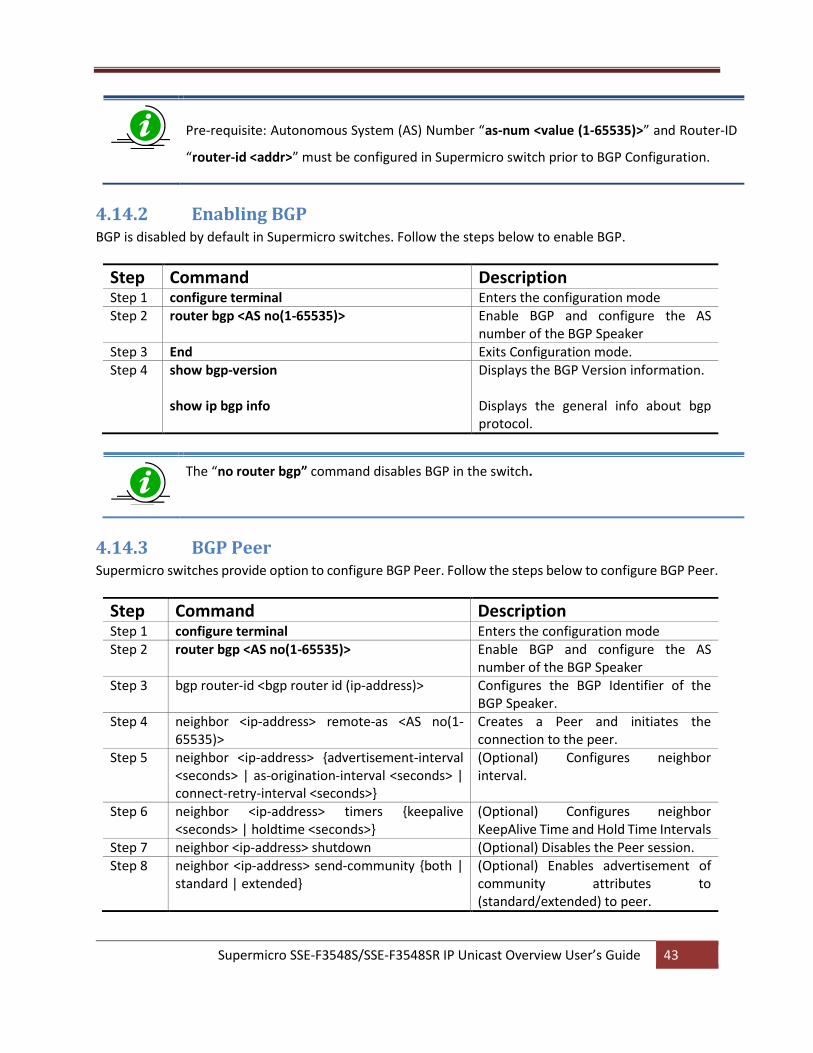
Supermicro SSE-F3548S/SSE-F3548SR IP Unicast Overview User’s Guide 43
Pre-requisite: Autonomous System (AS) Number “as-num <value (1-65535)>” and Router-ID
“router-id <addr>” must be configured in Supermicro switch prior to BGP Configuration.
4.14.2 Enabling BGP BGP is disabled by default in Supermicro switches. Follow the steps below to enable BGP.
Step Command Description Step 1 configure terminal Enters the configuration mode Step 2 router bgp <AS no(1-65535)> Enable BGP and configure the AS
number of the BGP Speaker Step 3 End Exits Configuration mode. Step 4 show bgp-version
show ip bgp info
Displays the BGP Version information. Displays the general info about bgp protocol.
The “no router bgp” command disables BGP in the switch.
4.14.3 BGP Peer Supermicro switches provide option to configure BGP Peer. Follow the steps below to configure BGP Peer.
Step Command Description Step 1 configure terminal Enters the configuration mode Step 2 router bgp <AS no(1-65535)> Enable BGP and configure the AS
number of the BGP Speaker Step 3 bgp router-id <bgp router id (ip-address)> Configures the BGP Identifier of the
BGP Speaker. Step 4 neighbor <ip-address> remote-as <AS no(1-
65535)> Creates a Peer and initiates the connection to the peer.
Step 5 neighbor <ip-address> {advertisement-interval <seconds> | as-origination-interval <seconds> | connect-retry-interval <seconds>}
(Optional) Configures neighbor interval.
Step 6 neighbor <ip-address> timers {keepalive <seconds> | holdtime <seconds>}
(Optional) Configures neighbor KeepAlive Time and Hold Time Intervals
Step 7 neighbor <ip-address> shutdown (Optional) Disables the Peer session. Step 8 neighbor <ip-address> send-community {both |
standard | extended} (Optional) Enables advertisement of community attributes to (standard/extended) to peer.
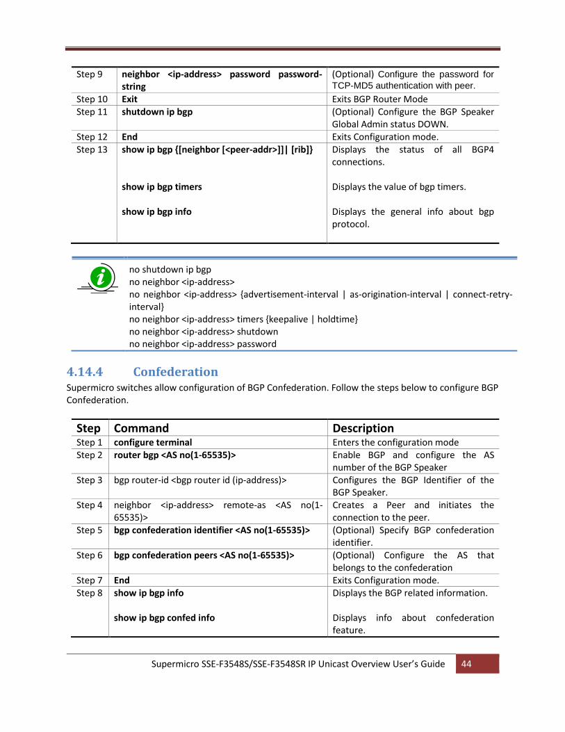
Supermicro SSE-F3548S/SSE-F3548SR IP Unicast Overview User’s Guide 44
Step 9 neighbor <ip-address> password password-string
(Optional) Configure the password for
TCP-MD5 authentication with peer.
Step 10 Exit Exits BGP Router Mode Step 11 shutdown ip bgp (Optional) Configure the BGP Speaker
Global Admin status DOWN. Step 12 End Exits Configuration mode. Step 13 show ip bgp {[neighbor [<peer-addr>]]| [rib]}
show ip bgp timers show ip bgp info
Displays the status of all BGP4 connections. Displays the value of bgp timers. Displays the general info about bgp protocol.
no shutdown ip bgp no neighbor <ip-address> no neighbor <ip-address> {advertisement-interval | as-origination-interval | connect-retry-interval} no neighbor <ip-address> timers {keepalive | holdtime} no neighbor <ip-address> shutdown no neighbor <ip-address> password
4.14.4 Confederation Supermicro switches allow configuration of BGP Confederation. Follow the steps below to configure BGP Confederation.
Step Command Description Step 1 configure terminal Enters the configuration mode Step 2 router bgp <AS no(1-65535)> Enable BGP and configure the AS
number of the BGP Speaker Step 3 bgp router-id <bgp router id (ip-address)> Configures the BGP Identifier of the
BGP Speaker. Step 4 neighbor <ip-address> remote-as <AS no(1-
65535)> Creates a Peer and initiates the connection to the peer.
Step 5 bgp confederation identifier <AS no(1-65535)> (Optional) Specify BGP confederation identifier.
Step 6 bgp confederation peers <AS no(1-65535)> (Optional) Configure the AS that belongs to the confederation
Step 7 End Exits Configuration mode. Step 8 show ip bgp info
show ip bgp confed info
Displays the BGP related information. Displays info about confederation feature.
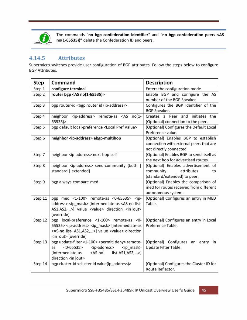
Supermicro SSE-F3548S/SSE-F3548SR IP Unicast Overview User’s Guide 45
The commands “no bgp confederation identifier” and “no bgp confederation peers <AS no(1-65535))” delete the Confederation ID and peers.
4.14.5 Attributes Supermicro switches provide user configuration of BGP attributes. Follow the steps below to configure BGP Attributes.
Step Command Description Step 1 configure terminal Enters the configuration mode Step 2 router bgp <AS no(1-65535)> Enable BGP and configure the AS
number of the BGP Speaker Step 3 bgp router-id <bgp router id (ip-address)> Configures the BGP Identifier of the
BGP Speaker. Step 4 neighbor <ip-address> remote-as <AS no(1-
65535)> Creates a Peer and initiates the (Optional) connection to the peer.
Step 5 bgp default local-preference <Local Pref Value> (Optional) Configures the Default Local Preference value.
Step 6 neighbor <ip-address> ebgp-multihop (Optional) Enables BGP to establish connection with external peers that are not directly connected
Step 7 neighbor <ip-address> next-hop-self (Optional) Enables BGP to send itself as the next hop for advertised routes.
Step 8 neighbor <ip-address> send-community {both | standard | extended}
(Optional) Enables advertisement of community attributes to (standard/extended) to peer.
Step 9 bgp always-compare-med (Optional) Enables the comparison of med for routes received from different autonomous system.
Step 11 bgp med <1-100> remote-as <0-65535> <ip-address> <ip_mask> [intermediate-as <AS-no list- AS1,AS2,...>] value <value> direction <in|out> [override]
(Optional) Configures an entry in MED Table.
Step 12 bgp local-preference <1-100> remote-as <0-65535> <ip-address> <ip_mask> [intermediate-as <AS-no list- AS1,AS2,...>] value <value> direction <in|out> [override]
(Optional) Configures an entry in Local Preference Table.
Step 13 bgp update-filter <1-100> <permit|deny> remote-as <0-65535> <ip-address> <ip_mask> [intermediate-as <AS-no list-AS1,AS2,...>] direction <in|out>
(Optional) Configures an entry in Update Filter Table.
Step 14 bgp cluster-id <cluster id value(ip_address)> (Optional) Configures the Cluster ID for Route Reflector.
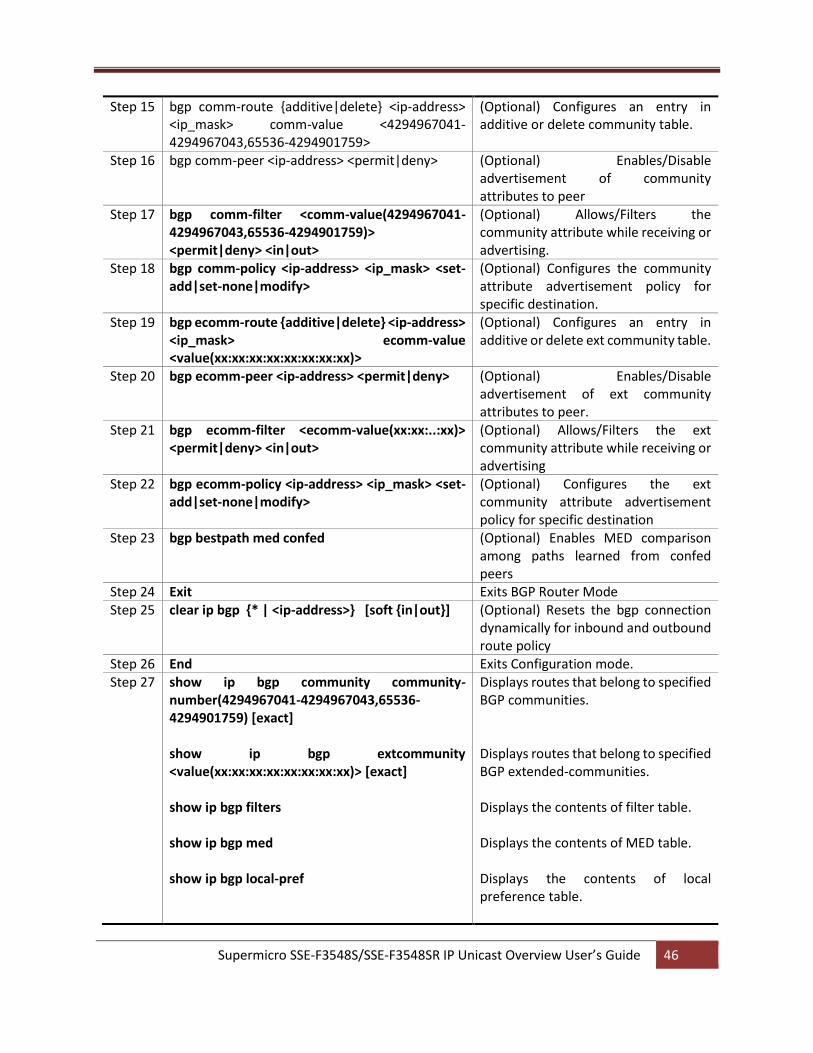
Supermicro SSE-F3548S/SSE-F3548SR IP Unicast Overview User’s Guide 46
Step 15 bgp comm-route {additive|delete} <ip-address> <ip_mask> comm-value <4294967041-4294967043,65536-4294901759>
(Optional) Configures an entry in additive or delete community table.
Step 16 bgp comm-peer <ip-address> <permit|deny> (Optional) Enables/Disable advertisement of community attributes to peer
Step 17 bgp comm-filter <comm-value(4294967041-4294967043,65536-4294901759)> <permit|deny> <in|out>
(Optional) Allows/Filters the community attribute while receiving or advertising.
Step 18 bgp comm-policy <ip-address> <ip_mask> <set-add|set-none|modify>
(Optional) Configures the community attribute advertisement policy for specific destination.
Step 19 bgp ecomm-route {additive|delete} <ip-address> <ip_mask> ecomm-value <value(xx:xx:xx:xx:xx:xx:xx:xx)>
(Optional) Configures an entry in additive or delete ext community table.
Step 20 bgp ecomm-peer <ip-address> <permit|deny> (Optional) Enables/Disable advertisement of ext community attributes to peer.
Step 21 bgp ecomm-filter <ecomm-value(xx:xx:..:xx)> <permit|deny> <in|out>
(Optional) Allows/Filters the ext community attribute while receiving or advertising
Step 22 bgp ecomm-policy <ip-address> <ip_mask> <set-add|set-none|modify>
(Optional) Configures the ext community attribute advertisement policy for specific destination
Step 23 bgp bestpath med confed (Optional) Enables MED comparison among paths learned from confed peers
Step 24 Exit Exits BGP Router Mode Step 25 clear ip bgp {* | <ip-address>} [soft {in|out}] (Optional) Resets the bgp connection
dynamically for inbound and outbound route policy
Step 26 End Exits Configuration mode. Step 27 show ip bgp community community-
number(4294967041-4294967043,65536-4294901759) [exact] show ip bgp extcommunity <value(xx:xx:xx:xx:xx:xx:xx:xx)> [exact] show ip bgp filters show ip bgp med show ip bgp local-pref
Displays routes that belong to specified BGP communities. Displays routes that belong to specified BGP extended-communities. Displays the contents of filter table. Displays the contents of MED table. Displays the contents of local preference table.
Supermicro SSE-F3548S/SSE-F3548SR IP Unicast Overview User’s Guide 47
show ip bgp info show ip bgp community {route|peer|policy|filter} show ip bgp extcommunity {route|peer|policy|filter}
Displays the general info about bgp protocol. Displays the contents of community tables. Displays the contents of ext-community tables.
no bgp default local-preference no neighbor <ip-address> ebgp-multihop no neighbor <ip-address> next-hop-self no neighbor <ip-address> send-community {both | standard |extended} no bgp always-compare-med no bgp med <1-100> no bgp local-preference <1-100> no bgp update-filter <1-100> no bgp cluster-id no bgp comm-route {additive|delete} <ip-address> <ip_mask> comm-value <4294967041-4294967043,65536-4294901759> no bgp comm-peer <ip-address> no bgp comm-filter <comm-value(4294967041-4294967043,65536-4294901759)> <permit|deny> <in|out> no bgp comm-policy <ip-address> <ip_mask> no bgp ecomm-route {additive|delete} <ip-address> <ip_mask> ecomm-value <value(xx:xx:xx:xx:xx:xx:xx:xx)> no bgp ecomm-peer <ip-address> no bgp ecomm-filter <ecomm-value(xx:xx:..:xx)> <permit|deny> <in|out> no bgp ecomm-policy <ip-address> <ip_mask> no bgp bestpath med confed
4.14.6 Route Reflection Supermicro switches allow users to configure Route Reflection. Follow the steps below to configure BGP Route Reflection.
Step Command Description Step 1 configure terminal Enters the configuration mode Step 2 router bgp <AS no(1-65535)> Enable BGP and configure the AS
number of the BGP Speaker Step 3 bgp router-id <bgp router id (ip-address)> Configures the BGP Identifier of the
BGP Speaker. Step 4 neighbor <ip-address> remote-as <AS no(1-
65535)> Creates a Peer and initiates the connection to the peer.
Supermicro SSE-F3548S/SSE-F3548SR IP Unicast Overview User’s Guide 48
Step 5 bgp client-to-client reflection (Optional) Configures the Route Reflector to support route reflection to Client Peers.
Step 6 neighbor <ip-address> route-reflector-client (Optional) Configures the Peer as Client of the Route Reflector.
Step 7 End Exits Configuration mode. Step 8 show ip bgp {[neighbor [<peer-addr>]]| [rib]}
show ip bgp info show ip bgp rfl info
Displays the status of all BGP4 connections. Displays the BGP related information. Displays info about Route Reflection feature.
Cluster ID must be configured before configuring Route Reflection. The “no bgp client-to-client reflection” command disables Route Reflection. The “no neighbor <ip-address> route-reflector-client” commands delete the Route reflection client.
4.14.7 Route Dampening Supermicro switches provide option to configure Route Dampening. Follow the steps below to configure BGP Route Dampening.
Step Command Description Step 1 configure terminal Enters the configuration mode Step 2 router bgp <AS no(1-65535)> Enable BGP and configure the AS
number of the BGP Speaker Step 3 bgp router-id <bgp router id (ip-address)> Configures the BGP Identifier of the
BGP Speaker. Step 4 neighbor <ip-address> remote-as <AS no(1-
65535)> Creates a Peer and initiates the connection to the peer.
Step 5 Exit Exits BGP Router Mode Step 6 ip bgp dampening [<HalfLife-Time> [<Reuse
Value> [<Suppress Value> [<Max-Suppress Time>]]]] [-s <Decay Granularity> [<Reuse Granularity> [<Reuse Array Size>]]]
(Optional) Configures the Dampening Parameters
Step 7 clear ip bgp <ip-address> flap-statistics (Optional) Clear flap-statistics counters for all paths from the neighbor at the IP address.
Step 8 End Exits Configuration mode. Step 9 show ip bgp dampening
show ip bgp info
Displays the contents of dampening table. Displays the BGP related information.
Supermicro SSE-F3548S/SSE-F3548SR IP Unicast Overview User’s Guide 49
show ip bgp dampened-paths show ip bgp flap-statistics [<ip-address><Mask>]
Displays the dampened routes. Displays the statistics of flapped routes.
The “no ip bgp dampening [HalfLife-Time [Reuse-Value [Suppress-Value [Max-Suppress-Time]]]] [-s [Decay-Granularity [Reuse-Granularity [Reuse-Array-Size]]]” command deletes the BGP Dampening Parameters.
4.14.8 Other Parameters Supermicro switches provide configuration of several BGP parameters, like Synchronization, redistribution etc. Follow the steps below to configure BGP parameters.
Step Command Description Step 1 configure terminal Enters the configuration mode Step 2 router bgp <AS no(1-65535)> Enable BGP and configure the AS
number of the BGP Speaker Step 3 bgp router-id <bgp router id (ip-address)> Configures the BGP Identifier of the
BGP Speaker. Step 4 bgp nonbgproute-advt <external|both> (Optional) Controls the advertisement
of Non-BGP routes either to the external peer (1) or both to internal & external peer (2)
Step 5 default-metric <Default Metric Value> (Optional) Configures the Default IGP Metric value.
Step 6 redistribute <static|connected|rip|ospf|all> (Optional) Configures the protocol from which the routes have to be redistributed into BGP.
Step 7 aggregate-address index <1-100> <ip-address> <ip_mask> [summary-only]
(Optional) Configures an entry in Aggregate Table.
Step 8 Exit Exits BGP Router Mode Step 9 ip bgp overlap-policy <more-specific|less-
specific|both> (Optional) Configures the Overlap Route policy for the Bgp Speaker.
Step 10 ip bgp synchronization (Optional) Enables synchronization between BGP and IGP.
Step 11 clear ip bgp {* | <ip-address>} [soft {in|out}] (Optional) sResets the bgp connection dynamically for inbound and outbound route policy
Step 12 End Exits Configuration mode. Step 13 show ip bgp info
show ip bgp aggregate
Displays the BGP related information. Displays the contents of aggregate table.
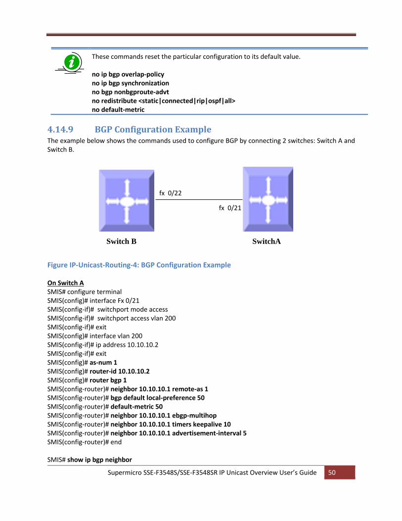
Supermicro SSE-F3548S/SSE-F3548SR IP Unicast Overview User’s Guide 50
These commands reset the particular configuration to its default value. no ip bgp overlap-policy no ip bgp synchronization no bgp nonbgproute-advt no redistribute <static|connected|rip|ospf|all> no default-metric
4.14.9 BGP Configuration Example The example below shows the commands used to configure BGP by connecting 2 switches: Switch A and Switch B.
Figure IP-Unicast-Routing-4: BGP Configuration Example On Switch A SMIS# configure terminal SMIS(config)# interface Fx 0/21 SMIS(config-if)# switchport mode access SMIS(config-if)# switchport access vlan 200 SMIS(config-if)# exit SMIS(config)# interface vlan 200 SMIS(config-if)# ip address 10.10.10.2 SMIS(config-if)# exit SMIS(config)# as-num 1 SMIS(config)# router-id 10.10.10.2 SMIS(config)# router bgp 1 SMIS(config-router)# neighbor 10.10.10.1 remote-as 1 SMIS(config-router)# bgp default local-preference 50 SMIS(config-router)# default-metric 50 SMIS(config-router)# neighbor 10.10.10.1 ebgp-multihop SMIS(config-router)# neighbor 10.10.10.1 timers keepalive 10 SMIS(config-router)# neighbor 10.10.10.1 advertisement-interval 5 SMIS(config-router)# end SMIS# show ip bgp neighbor
fx 0/21
fx 0/22
Switch B SwitchA
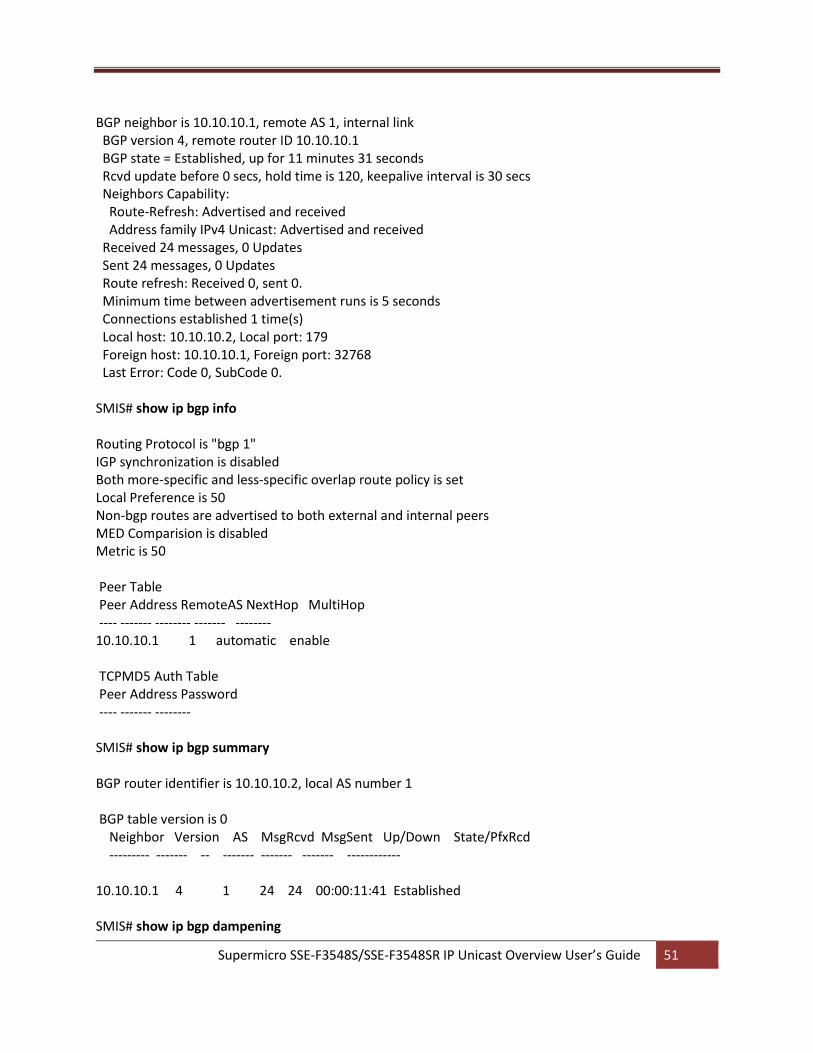
Supermicro SSE-F3548S/SSE-F3548SR IP Unicast Overview User’s Guide 51
BGP neighbor is 10.10.10.1, remote AS 1, internal link BGP version 4, remote router ID 10.10.10.1 BGP state = Established, up for 11 minutes 31 seconds Rcvd update before 0 secs, hold time is 120, keepalive interval is 30 secs Neighbors Capability: Route-Refresh: Advertised and received Address family IPv4 Unicast: Advertised and received Received 24 messages, 0 Updates Sent 24 messages, 0 Updates Route refresh: Received 0, sent 0. Minimum time between advertisement runs is 5 seconds Connections established 1 time(s) Local host: 10.10.10.2, Local port: 179 Foreign host: 10.10.10.1, Foreign port: 32768 Last Error: Code 0, SubCode 0. SMIS# show ip bgp info Routing Protocol is "bgp 1" IGP synchronization is disabled Both more-specific and less-specific overlap route policy is set Local Preference is 50 Non-bgp routes are advertised to both external and internal peers MED Comparision is disabled Metric is 50 Peer Table Peer Address RemoteAS NextHop MultiHop ---- ------- -------- ------- -------- 10.10.10.1 1 automatic enable TCPMD5 Auth Table Peer Address Password ---- ------- -------- SMIS# show ip bgp summary BGP router identifier is 10.10.10.2, local AS number 1 BGP table version is 0 Neighbor Version AS MsgRcvd MsgSent Up/Down State/PfxRcd --------- ------- -- ------- ------- ------- ------------ 10.10.10.1 4 1 24 24 00:00:11:41 Established SMIS# show ip bgp dampening
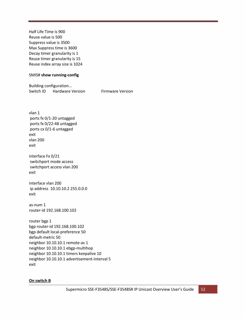
Supermicro SSE-F3548S/SSE-F3548SR IP Unicast Overview User’s Guide 52
Half Life Time is 900 Reuse value is 500 Suppress value is 3500 Max Suppress time is 3600 Decay timer granularity is 1 Reuse timer granularity is 15 Reuse index array size is 1024 SMIS# show running-config Building configuration... Switch ID Hardware Version Firmware Version vlan 1 ports fx 0/1-20 untagged ports fx 0/22-48 untagged ports cx 0/1-6 untagged exit vlan 200 exit interface Fx 0/21 switchport mode access switchport access vlan 200 exit interface vlan 200 ip address 10.10.10.2 255.0.0.0 exit as-num 1 router-id 192.168.100.102 router bgp 1 bgp router-id 192.168.100.102 bgp default local-preference 50 default-metric 50 neighbor 10.10.10.1 remote-as 1 neighbor 10.10.10.1 ebgp-multihop neighbor 10.10.10.1 timers keepalive 10 neighbor 10.10.10.1 advertisement-interval 5 exit On switch B
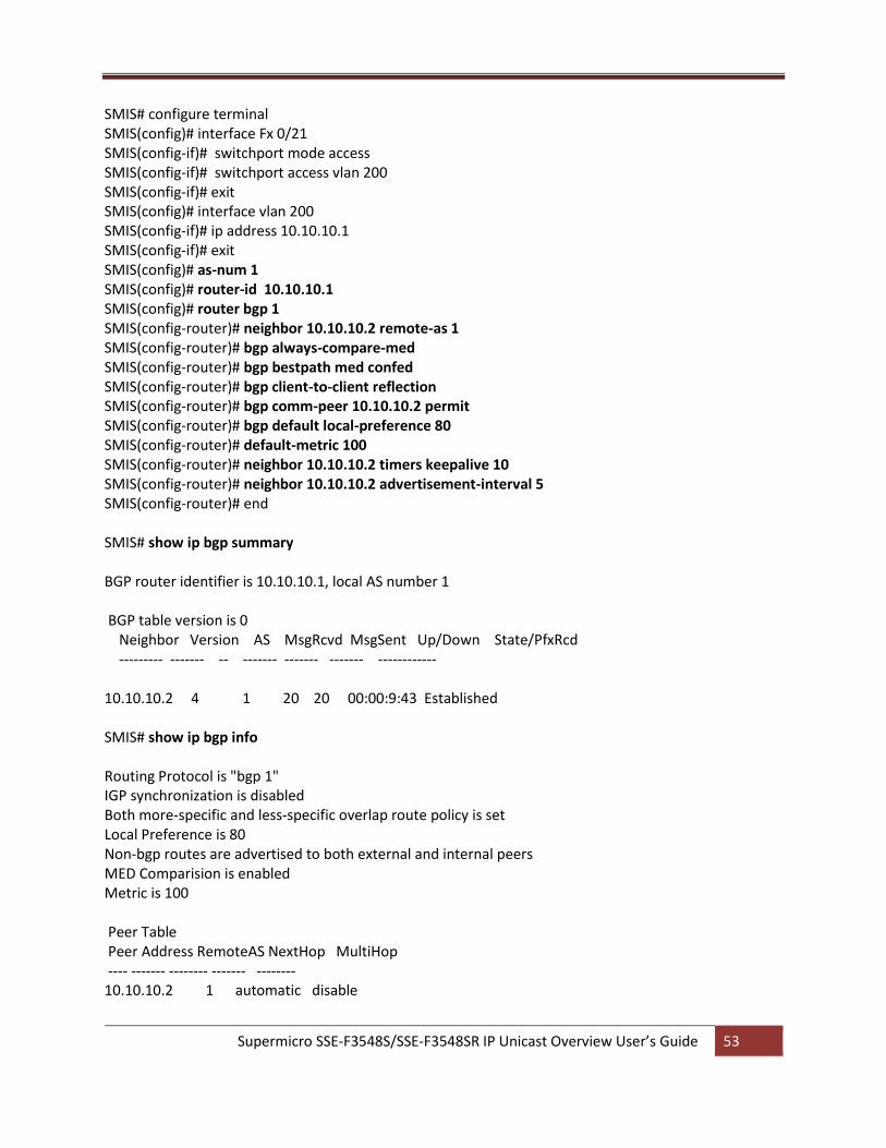
Supermicro SSE-F3548S/SSE-F3548SR IP Unicast Overview User’s Guide 53
SMIS# configure terminal SMIS(config)# interface Fx 0/21 SMIS(config-if)# switchport mode access SMIS(config-if)# switchport access vlan 200 SMIS(config-if)# exit SMIS(config)# interface vlan 200 SMIS(config-if)# ip address 10.10.10.1 SMIS(config-if)# exit SMIS(config)# as-num 1 SMIS(config)# router-id 10.10.10.1 SMIS(config)# router bgp 1 SMIS(config-router)# neighbor 10.10.10.2 remote-as 1 SMIS(config-router)# bgp always-compare-med SMIS(config-router)# bgp bestpath med confed SMIS(config-router)# bgp client-to-client reflection SMIS(config-router)# bgp comm-peer 10.10.10.2 permit SMIS(config-router)# bgp default local-preference 80 SMIS(config-router)# default-metric 100 SMIS(config-router)# neighbor 10.10.10.2 timers keepalive 10 SMIS(config-router)# neighbor 10.10.10.2 advertisement-interval 5 SMIS(config-router)# end SMIS# show ip bgp summary BGP router identifier is 10.10.10.1, local AS number 1 BGP table version is 0 Neighbor Version AS MsgRcvd MsgSent Up/Down State/PfxRcd --------- ------- -- ------- ------- ------- ------------ 10.10.10.2 4 1 20 20 00:00:9:43 Established SMIS# show ip bgp info Routing Protocol is "bgp 1" IGP synchronization is disabled Both more-specific and less-specific overlap route policy is set Local Preference is 80 Non-bgp routes are advertised to both external and internal peers MED Comparision is enabled Metric is 100 Peer Table Peer Address RemoteAS NextHop MultiHop ---- ------- -------- ------- -------- 10.10.10.2 1 automatic disable
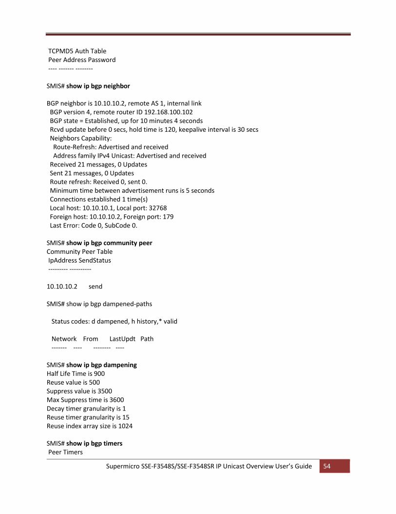
Supermicro SSE-F3548S/SSE-F3548SR IP Unicast Overview User’s Guide 54
TCPMD5 Auth Table Peer Address Password ---- ------- -------- SMIS# show ip bgp neighbor BGP neighbor is 10.10.10.2, remote AS 1, internal link BGP version 4, remote router ID 192.168.100.102 BGP state = Established, up for 10 minutes 4 seconds Rcvd update before 0 secs, hold time is 120, keepalive interval is 30 secs Neighbors Capability: Route-Refresh: Advertised and received Address family IPv4 Unicast: Advertised and received Received 21 messages, 0 Updates Sent 21 messages, 0 Updates Route refresh: Received 0, sent 0. Minimum time between advertisement runs is 5 seconds Connections established 1 time(s) Local host: 10.10.10.1, Local port: 32768 Foreign host: 10.10.10.2, Foreign port: 179 Last Error: Code 0, SubCode 0. SMIS# show ip bgp community peer Community Peer Table IpAddress SendStatus --------- ---------- 10.10.10.2 send SMIS# show ip bgp dampened-paths Status codes: d dampened, h history,* valid Network From LastUpdt Path ------- ---- -------- ---- SMIS# show ip bgp dampening Half Life Time is 900 Reuse value is 500 Suppress value is 3500 Max Suppress time is 3600 Decay timer granularity is 1 Reuse timer granularity is 15 Reuse index array size is 1024 SMIS# show ip bgp timers Peer Timers
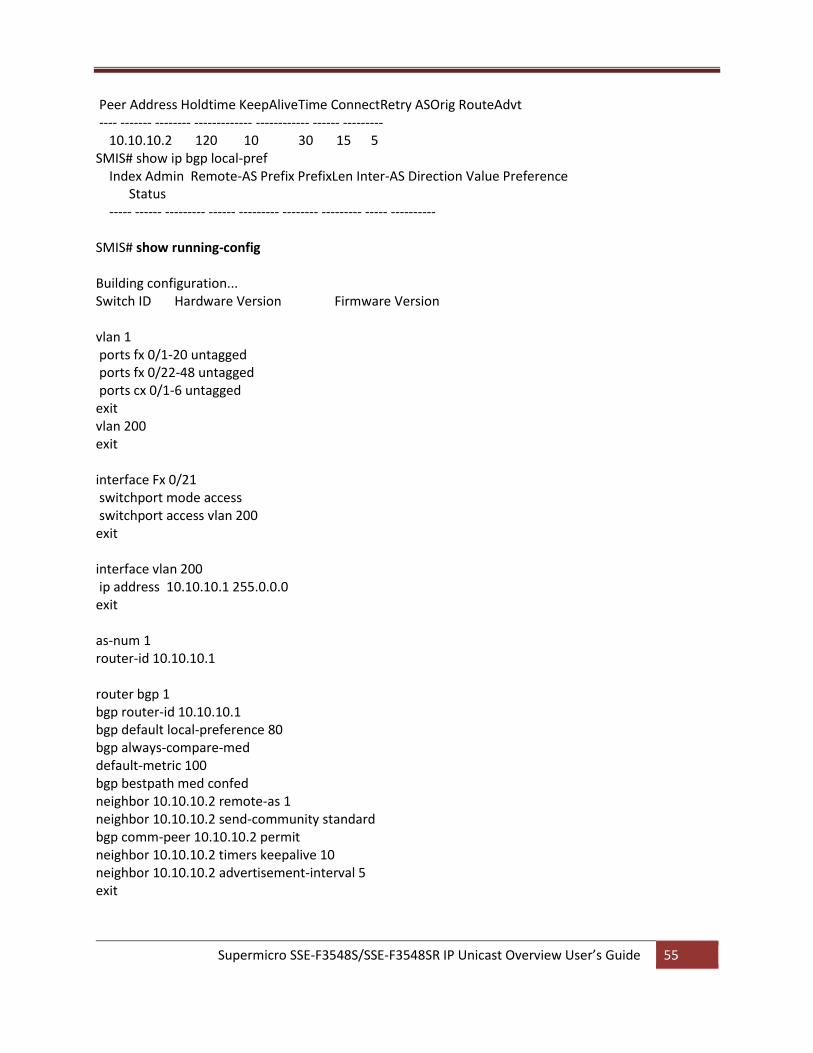
Supermicro SSE-F3548S/SSE-F3548SR IP Unicast Overview User’s Guide 55
Peer Address Holdtime KeepAliveTime ConnectRetry ASOrig RouteAdvt ---- ------- -------- ------------- ------------ ------ --------- 10.10.10.2 120 10 30 15 5 SMIS# show ip bgp local-pref Index Admin Remote-AS Prefix PrefixLen Inter-AS Direction Value Preference Status ----- ------ --------- ------ --------- -------- --------- ----- ---------- SMIS# show running-config Building configuration... Switch ID Hardware Version Firmware Version vlan 1 ports fx 0/1-20 untagged ports fx 0/22-48 untagged ports cx 0/1-6 untagged exit vlan 200 exit interface Fx 0/21 switchport mode access switchport access vlan 200 exit interface vlan 200 ip address 10.10.10.1 255.0.0.0 exit as-num 1 router-id 10.10.10.1 router bgp 1 bgp router-id 10.10.10.1 bgp default local-preference 80 bgp always-compare-med default-metric 100 bgp bestpath med confed neighbor 10.10.10.2 remote-as 1 neighbor 10.10.10.2 send-community standard bgp comm-peer 10.10.10.2 permit neighbor 10.10.10.2 timers keepalive 10 neighbor 10.10.10.2 advertisement-interval 5 exit

Supermicro SSE-F3548S/SSE-F3548SR IP Unicast Overview User’s Guide 56
Supermicro SSE-F3548S/SSE-F3548SR IP Unicast Overview User’s Guide 57
Contacting Supermicro Headquarters Address: Super Micro Computer, Inc.
980 Rock Ave. San Jose, CA 95131 U.S.A.
Tel: +1 (408) 503-8000 Fax: +1 (408) 503-8008 Email: [email protected] (General Information)
[email protected] (Technical Support) Web Site: www.supermicro.com Europe Address: Super Micro Computer B.V.
Het Sterrenbeeld 28, 5215 ML 's-Hertogenbosch, The Netherlands
Tel: +31 (0) 73-6400390 Fax: +31 (0) 73-6416525 Email: [email protected] (General Information)
[email protected] (Technical Support) [email protected] (Customer Support)
Web Site: www.supermicro.com.nl Asia-Pacific Address: Super Micro Computer, Inc.
3F, No. 150, Jian 1st Rd. Zhonghe Dist., New Taipei City 235 Taiwan (R.O.C)
Tel: +886-(2) 8226-3990 Fax: +886-(2) 8226-3992 Email: [email protected] Web Site: www.supermicro.com.tw


![1 Two Unicast Information Flows over Linear Deterministic ...web.eng.ucsd.edu/~sukamath/two_unicast_linear... · unicast problem, in [1] Wang and Shroff study the solvability of two-unicast](https://img.pdfslide.us/doc/110x75/6107c99ad649e33b30210889/1-two-unicast-information-flows-over-linear-deterministic-webengucsdedusukamathtwounicastlinear.jpg)